velocity vortex 2016-2017 first tech challenge … · 1 velocity vortexsm 2016-2017 first® tech...
TRANSCRIPT

1
VELOCITY VORTEXSM
2016-2017 FIRST® Tech Challenge
Field Assembly Guide
AndyMark® Field Components for 2016-2017 FIRST® Tech Challenge
Rev 1.3W
2
This guide contains instructions for assembling the Field Elements for the
2016-2017 FIRST® Tech Challenge Game VELOCITY VORTEXSM.
Videos can also be found on the How to/Pictures tab on each AndyMark.com product page.
REVISION HISTORY
Rev. Date Description
1.0 7/8/16 Initial Printed Release
1.1 7/11/16 Added part numbers to steps, adjusted typos.
1.1W 8/10/16 Reformat for Web and
1.2W 8/17/16 Minor Changes
1.3W 9/8/16 Minor Changes
ASSEMBLY VIDEOS CAN BE FOUND ON OUR WEBSITE: AndyMark.com/FTCVideo
Read through all the instructions and take a parts inventory before you
begin to assemble the game elements!
CAUTION! Edges of field parts may be sharp. File or deburr sharp corners or edges as needed.

3
TOOLS NEEDED Component QTY Part Photo
Safety Equipment
Rivet Gun 1
3/8 Nut Driver or Socket 1
7/16 1
1
Drill 1
7/32 Drill Bit 1
Zip Tie Cutters 1
5/32 Hex Key Driver 1
#0 Small Philips Screwdriver 1
#2 Philips Screwdriver 1
File 1
Tape Measure 1
Hammer 1
Rubber Mallet 1
Black Paint & Paintbrush (Official Events Only)
olor code DC4B-10-5, semi gloss (base 3300)
1
9V Battery 1
Tools can be purchased as a tool set from AndyMark

4
CORNER VORTEX (CV) *Quantities listed are for each vortex, one red and one blue vortex are needed per field.
Component Part # QTY* Part Photo
Ramp Box
CV Side Support am-3383 2
CV Surface Half (Red OR Blue) am-3384R/B 2 OR
Ball Return Slope am-3385 2
Center Spine am-3386 1
Crossbar am-3387 1
CV Hardware Pack
NOTE: TFS = Thread Forming Screw SHCS=Socket Head Cap Screw
Peanut Standoff am-3090_03 4
90° Bolt Bracket am-2846 10
HD Zip Ties am-1067 8
1/4-20 x 1.00 TFS am-1182 8
10-32 x 1.00 SHCS am-1056 2
10-32 x 0.75 SHCS am-1047 6
#10 Washers am-1026 6
10-32 Nyloc Jam Nut am-1063 8
et am-1410 10
NOTE: TFS = Thread Forming Screw SHCS=Socket Head Cap Screw

5
CENTER VORTEX ASSEMBLY NOTE: One Center Vortex Assembly is needed per field.
Component Part # QTY Part Photo
Vortex Spoke RED am-3359R 7
Vortex Spoke BLUE am-3359B 7
Sheet Plastic Cone am-3365 2
Pipe RED am-3366R_057 1
Pipe RED am-3366R_095 7 Pipe RED am-3366R_130 7 Pipe BLUE am-3366B_057 1
Pipe BLUE am-3366B_095 7 Pipe BLUE am-3366B_130 7
Center Vortex Circle am-3373 4
Anti-Rotation Device am-3388 2
HD Zip Ties am-1067 12
Base Plate
am-3379 1
Steel Pipe am-3380 1
Steel Flange am-3381 1
PVC Tee Joint am-3367 1
PVC Elbow am-3369 2
PVC Vertical Pole am-3368_vp 1
PVC Crossbar am-3368_cb 2
1. - am-3370 2
Spacer Donut am-3371 1

6
Center Vortex Hardware Pack NOTE: FHS = Flat Head Screw SHCS=Socket Head Cap Screw
10-32 x am-1014 14
10-32 Nyloc Jam Nut am-1063 19
#10 Washer am-1026 28
¼- FHS am-1409 4
¼-20 Spike Tee Nut am-1079 4
10-32 x 2.250 SHCS am-1156 5
Rubber Standoff am-3382 5 NOTE: FHS = Flat Head Screw SHCS=Socket Head Cap Screw
Beacon Parts NOTE: Four Beacons are needed per field.
Component Part # QTY Part Photo
2017 Electronics Board am-3011_board 1 Wire am-3011_twistedwire 3
Button am-3182 3
9V Battery Terminal am-3411 1
2017 Beacon Housing am-3011a_housing 2
Beacon Hardware Pack
BHCS=Button Head Cap Screw SHCS=Socket Head Cap Screw TFS = Thread Forming Screw
Beacon C-Clamp Left am-3391L 1
Beacon C-Clamp Right am-3391R 1
10- am-1007 2
10-32 X 0.375 BHCS Phillips
am-1028 2
10-32 Nyloc Jam Nut am-1063 2
10- TFS am-1355 4
BHCS=Button Head Cap Screw SHCS=Socket Head Cap Screw TFS = Thread Forming Screw
7
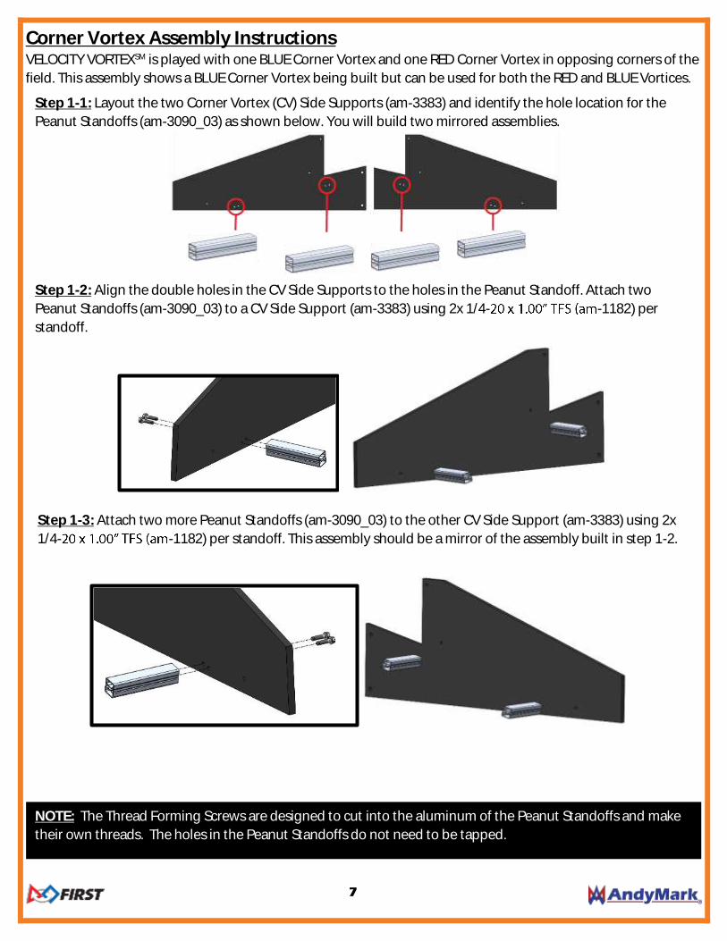
Step 1-3: Attach two more Peanut Standoffs (am-3090_03) to the other CV Side Support (am-3383) using 2x
1/4- -1182) per standoff. This assembly should be a mirror of the assembly built in step 1-2.
NOTE: The Thread Forming Screws are designed to cut into the aluminum of the Peanut Standoffs and make
their own threads. The holes in the Peanut Standoffs do not need to be tapped.
Step 1-3: Layout the two ramp side supports (am-333) and the Peanut Standoffs as shown.
Corner Vortex Assembly Instructions VELOCITY VORTEXSM is played with one BLUE Corner Vortex and one RED Corner Vortex in opposing corners of the
field. This assembly shows a BLUE Corner Vortex being built but can be used for both the RED and BLUE Vortices.
Step 1-1: Layout the two Corner Vortex (CV) Side Supports (am-3383) and identify the hole location for the
Peanut Standoffs (am-3090_03) as shown below. You will build two mirrored assemblies.
Step 1-2: Align the double holes in the CV Side Supports to the holes in the Peanut Standoff. Attach two
Peanut Standoffs (am-3090_03) to a CV Side Support (am-3383) using 2x 1/4- -1182) per
standoff.
8
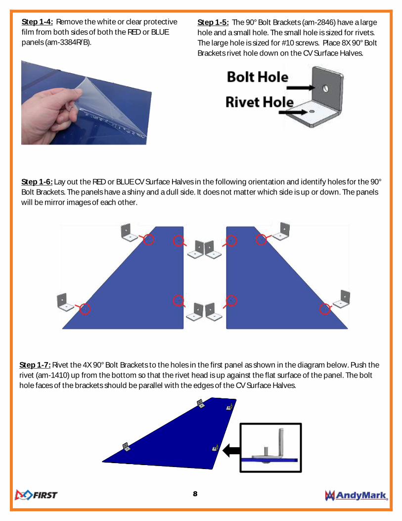
Step 1-6: Lay out the RED or BLUE CV Surface Halves in the following orientation and identify holes for the 90°
Bolt Brackets. The panels have a shiny and a dull side. It does not matter which side is up or down. The panels
will be mirror images of each other.
Step 1-7: Rivet the 4X 90° Bolt Brackets to the holes in the first panel as shown in the diagram below. Push the
rivet (am-1410) up from the bottom so that the rivet head is up against the flat surface of the panel. The bolt
hole faces of the brackets should be parallel with the edges of the CV Surface Halves.
Step 1-5: The 90° Bolt Brackets (am-2846) have a large
hole and a small hole. The small hole is sized for rivets.
The large hole is sized for #10 screws. Place 8X 90° Bolt
Brackets rivet hole down on the CV Surface Halves.
Step 1-4: Remove the white or clear protective
film from both sides of both the RED or BLUE
panels (am-3384R/B).

9
Step 1-9: Place the CV Center Spine (am-3386) between
the CV Surface Half Assemblies in the following
orientation with the longest edge facing up.
Step 1-10: Secure the CV Center Spine to the
90° bolt brackets on both sides using 2X 10-32 x
1.00 -1056) and 10-32 Nyloc Jam Nut
(am-1063). No washers are needed for these
screws.
Step 1-11: Place the CV Side Support Assemblies along the side of the Ramp Halves in the following
orientations with the Peanut Standoffs facing away from the CV Surface Halves.
Step 1-8: Attach the 4X 90° Bolt Brackets (am-2846) to the holes in the second panel as shown in the diagram
below. This panel should be a mirror image of the panel assembled in step 1-7. Push the rivet up from the
bottom so that the rivet head is up against the flat surface of the panel. The bolt hole faces of the brackets
should be parallel with the edges of the CV Surface Halves.

10
Step 1-13: The brackets holding the CV Side Supports
will need to be bent. Take each CV Side Support and
bend until the end of each support lines up with the CV
Center Spline.
Step 1-12: Secure each 90° Degree Bolt Bracket
(two per side) to a CV Side Support using a 10-32 x
-1047), #10 Washer (am-1026) and
Nyloc Jam Nut (am-1063).
Step 1-14: Use 2 Zip Ties to secure the CV Center Spine to the CV Side Supports. The Zip Tie should pass
through all four holes and be secured so that the Sp
each Zip Tie.
Step 1-15: Flip the Corner Vortex Assembly over and place one Ball Return Slope on each side on top of the
Peanut Standoffs. Secure both Slopes to the CV Center Spine using Two Zip Ties. The Zip Tie should pass
through both slopes and the CV Center Spine. Cut the excess tail of each Zip Tie.

11
Step 1-16: Use 4X Zip Ties to secure the Ball Return Slopes to the Peanut Standoffs. The Slopes should rest on
top of the lower screws on the CV Side Supports. Cut the excess tail of each Zip Tie.
Step 1-19: The BLUE Corner Vortex is complete. Repeat the assembly for the RED Corner Vortex.
Step 1-17: Rivet the 2X remaining 90° bolt Brackets to the small holes on the Crossbar (am-3387). Push the rivet
up from the bottom so that the rivet head is up against the flat surface of the Crossbar.
Step 1-18: Using 2X 10-32 x 0.75 -1047), #10 Washers, and 10-32 Nyloc Jam Nut secure the Crossbar
to the Corner Vortex Assembly. The Crossbar will span across the top of the CV Side Supports with the edges
aligned.

12
Center Vortex Assembly Base Plate Assembly Instructions
Step 2-1: Locate the Base Plate and flip upside down
with the recessed circles facing downward.
Step 2-3 Place 5X Rubber Standoffs (am-3382) in
the following locations on the bottom of the Base
Plate on the same side as the Spike Tee Nuts.
Step 2-4: Flip the Base Plate over and attach the
Steel Flange (am-3381) by screwing 4X 1/4-20 x
-1409) into the Spike Tee Nuts.
Step 2-5: Screw the Steel Pipe (am-3380) into
the Steel Flange on the Base Plate.
Step 2-2: Take 4X 1/4-20 Spike Tee Nuts (am-1079)
and hammer one per hole into the bottom of the
base plate. The spikes will dig into the plywood
and the nut should be flush with the bottom
surface.
Step 2-6: Screw the Spacer Donut (am-3371)
onto the threads of Steel Pipe. The donut should
be pushed onto the pipe as far as it can until it
stops moving.
Note: For Official Events, the base plate must be painted black using Behr black, color code DC4B-10-5, semi gloss (base 3300) .
13
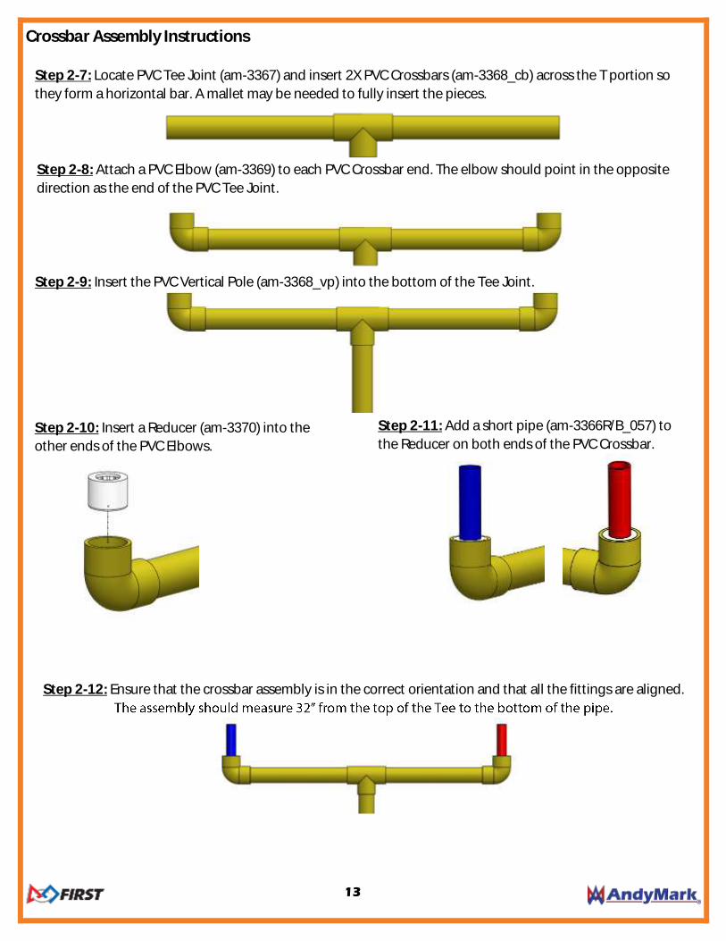
Crossbar Assembly Instructions
Step 2-11: Add a short pipe (am-3366R/B_057) to
the Reducer on both ends of the PVC Crossbar.
Step 2-10: Insert a Reducer (am-3370) into the
other ends of the PVC Elbows.
Step 2-8: Attach a PVC Elbow (am-3369) to each PVC Crossbar end. The elbow should point in the opposite
direction as the end of the PVC Tee Joint.
Step 2-7: Locate PVC Tee Joint (am-3367) and insert 2X PVC Crossbars (am-3368_cb) across the T portion so
they form a horizontal bar. A mallet may be needed to fully insert the pieces.
Step 2-9: Insert the PVC Vertical Pole (am-3368_vp) into the bottom of the Tee Joint.
Step 2-12: Ensure that the crossbar assembly is in the correct orientation and that all the fittings are aligned.

14
Vortex Basket Assembly Instructions
Step 2-16: Locate 7X RED Vortex Spokes (am-3359R)
and 2 Center Vortex Circles (am-3373).
Step 2-17: Attach a Center Vortex Circle to the top and
bottom of a Vortex Spoke using a 10-
(am-1014), #10 Washer on each side, and 10-32 Nyloc
Jam Nut. Be careful not to over tighten screws as to not
crush the circles.
Step 2-18: Continue adding 6X Vortex Spokes to the assembly overlapping the ends to form a ring.
Step 2-13: Using a 7/32 drill bit, drill a hole through the connectors and pipes in the following locations.
Step 2-14: Secure all 5 locations with 10-
SHCS (am-1156) and 10-32 Nyloc Jam Nuts (am-1063).
Step 2-15: Place Crossbar Assembly onto base plate
assembly.

15
Step 2-19: There are 3 lengths of pipe for each
Vortex. The 7 long and 7 medium pipes shown
below will be placed around the ring.
Step 2-20: Using a pushing and twisting motion,
insert the 7 medium length pipes (am-3366R_095)
measuring 9.5
sockets around the ring. These pipes will hold the
ring together.
Step 2-21: Using a pushing and twisting
motion, add the long pipes (am-3366R_130) to
the middle sockets.
Step 2-22: Repeat steps 2-16 to 2-21 for the
BLUE Vortex.
Step 2-23: Wrap a plastic sheet cone (am-3365) around
each short pipe and crossbar.

16
Step 2-25: Slide each Vortex onto the short pipe of
matching color on the PVC Crossbar.
Step 2-26: Locate Anti-Rotation Device (am-
3388) and place it in the following location
between the Crossbar and the basket.
Step 2-24: Secure each cone at the inner and outer edge with 2 Zip Ties and tighten so the cone is secure. On
the outer edge of the cone, the holes nearest to the edge will overlap. On the inner edge the holes will not
overlap. The Zip Tie heads should sit on the underside of the cone. Cut the excess tail of each Zip Tie.
Step 2-28: The Center Vortex Assembly is
now complete!
Step 2-27: Secure the Anti-Rotation (am-3388)
Device to the Vortex Spoke using two Zip Ties.
Next, attach the Anti-Rotation device to the
Crossbar using two Zip Ties.

17
Beacon Assembly Instructions
Step 3-1:
attach three Buttons (am-3182) to the Housing halves (am-3011a-housing). Be sure to securely tighten the nut
on the inside of the Housing.
Step 3-5: Using a small Phillips screwdriver loosen
the two screws on the button until one wire can be
pushed into the hole.
Step 3-4: The wires (am-3011_twistedwire) should
already have the ends scored. Ensure that the metal is
fully exposed by pulling off any insulation left on the
wire ends.
Step 3-3: Layout the Beacon Housings so that the
bottoms are touching.
Step 3-2: Mount the Electronics Board (am-
3011_board) to the Beacon Housing with one button
attached using 2x 10-32 x 0.375" BHCS (am-1028).

18
Step 3-8: Each button plugs into the section of the connector matching the name in the diagram below. It
does not matter which end of each twisted pair goes to each hole.
Step 3-10: Once all three buttons are wired,
gently tug each wire to verify they are all securely
fastened. The wires should remain in the
connector when gently pulled.
Step 3-9: To insert a wire into the connector insert a
small screwdriver into the hole directly above the hole
for the wire. This will open the connector and the wire
can be pushed by hand into the connector.
Step 3-6: Take a twisted wire pair and insert one metal
lead into each hole on the button. Tighten down the
screws to secure the wires. Repeat for the remaining
two buttons.
Step 3-7: Locate the beacon button connector on the
circuit board. Each wire will plug into the lower row of
holes on the connector in each labeled spot.

19
Step 3-15: Add the Beacon Brackets (am-3391R/L) to
the side of the beacon. The flange of the bracket
should face away from the side with two buttons.
Step 3-14: Carefully close the beacon halves. Be
careful not to pinch the Wires.
Step 3-16: Secure the beacon halves by adding a 10-
-1355) screw to the top and side
holes.
Additional instructions on the following can be found in the
Field Setup and Configuration Guide Available on AndyMark.com/FTC
Setting up the Floor and Field Perimeter
Instructions for Field Layout and Orientation
Tournament Setup
http://www.firstinspires.org/roboticsprograms/ftc
Step 3-12: Verify that the beacon is wired correctly
by attaching a 9V battery. If setup correctly, a
startup light sequence will run. If the correct 2016-
2017 program is running on the beacon board the
lights will show the following sequence during
startup.
Step 3-13: If the lights do not illuminate when a
charged battery is connected, check to ensure the
wires are secure and connected to the correct places. If
the light pattern does not match and show green
lights, the beacon board may need to be
reprogrammed for the 2016-2017 game.
Step 3-11: Attach the 9V pigtail (am-3411) to the power
connector on the circuit board.
Additional hardware will be left over and used for attaching components to the field. Extra hardware should be kept and not discarded.