volume 7, no. 1 august, 2004 vlt newsradovinsky/papers/46.pdf · volume 7, no. 1 august, 2004...
TRANSCRIPT
Volume 7, No. 1 August, 2004
Volume 7, No. 1 August, 2004
In This Issue
• Advanced Tokamak Modes in ITER and FIRE D. Meade, PPPL
• First Integrated Test of Superconducting Magnet Systems for the
Levitated Dipole Experiment (LDX) A. Zhukovsky, P. C. Michael, J. H. Schultz, B. A. Smith, J. V. Minervini, J. Kesner, A. Radovinsky, MIT Plasma Science and Fusion Center, D. Garnier, M. Mauel. Columbia University
• Experimental Target Injection and Tracking System Designed and Constructed at GA
R. Petzoldt, B. Vermillion and D. Goodin, General Atomics
• Ancillary Systems for Dual Coolant Liquid Breeder Test Blanket Modules
C. Wong (GA), M. Abdou(UCLA), D.P. Carosella (GA), M. Dagher (UCLA), M.P. Labar, S. Malang (Consultant), B. Merrill (INEEL), N. Morley (UCLA), M. Sawan (UW), R.S. Willms (LANL), D. Sze UCSD)
Lab Notes
Calendar
VLT NewsThe Newsletter for the Virtual Laboratory for Technology

August, 2004 Volume 7, No. 1
Advanced Tokamak Modes in ITER and FIRE
The need for advanced tokamak (AT) modes capable of steady-state and high-power-density operation in a magnetic fusion power plant was recognized in the late 1970s, and resulted in the formation of the US Advanced Tokamak Program in 1979. A series of Advanced Reactor Innovation Evaluation Studies (ARIES) in the 1990s quantified the impact of steady-state and high-power-density on the economic attractiveness of a tokamak based power plant. The discovery of the reversed shear (negative central shear) AT mode by Kessel (US) and Ozeki (JA) in 1992 opened the way for self-consistent steady-state high-power-density advanced tokamak operating modes. Systematic investigation of reversed shear (negative central shear) AT modes began in 1994 on TFTR and DIII-D, and a significant effort is now being carried out by the international tokamak research program. An attractive steady-state power plant will require a large fraction (70 - 90%) of the plasma current to be driven by the bootstrap effect with the remainder driven by neutral beams or RF waves. Good progress was made in the 1980s and 90s in developing the physics basis and technology needed to drive plasma current using neutral beams, and various RF frequency waves - fast wave ion cyclotron, lower hybrid and electron cyclotron. In addition, self-driven (bootstrap) currents up to 80% have been produced in a number of tokamaks for short pulses. The ARIES power plant studies had fusion power densities of ~5 MWm-3 , which will require �B2 sufficient to produce volume average plasma pressures, �p�, of 10 atmospheres (atm). Progress toward achieving the plasma pressure needed for a MFE power plant is shown in Fig. 1.
VLT NewsThe Newsletter for the Virtual Laboratory for Technology
Fig.1. Plasma pressure relative to maximum magnetic field at the toroidal field coil

August, 2004 Volume 7, No. 1
Plasma pressures of just over 1 atm have been achieved in several tokamaks including; Alcator C, C-Mod, TFTR, JT-60U, JET and DIII-D. The maximum pressure of 1.6 atm was achieved by Alcator C in 1983 using only ohmic heating. Strongly shaped plasmas like PBX-M and NSTX have achieved plasma pressures of 0.3 atm and 0.25 atm respectively. The maximum plasma pressure is limited by a combination of plasma physics, coil geometry and engineering as shown by the three terms in Eq. 1 below. ⟨p⟩ = βto Bto
2 = βto (Bto/Bcoil)2 Bcoil2 (1)
= βfusion Bcoil
2 (2)
For superconducting coils, Bcoil is subject to the limits of electromagnetic stress and the superconducting transition field while normal conducting coils are subject to the limits of electromagnetic and thermal stress as well as coil power dissipation. The operational limits for various coil systems are also shown in Fig 1. Therefore, the appropriate “Figure of Merit” for utilization of magnetic field in a magnetic fusion reactor is βfusion = ⟨p⟩/ Bcoil
2 where Bcoil is the maximum field achievable at the toroidal field coil as shown in Eq. 2 above. As shown in Fig 1, the achieved βfusion ranges from 0.2% to 1%. A variety of power plant design studies and burning plasma experiments proposals are also shown on Fig. 1 with power plant designs in the range of βfusion= 1 – 2% that would result in plasma pressures of 10 atm and DT power densities of 5 MW-3. The ongoing tokamak program and a next step burning plasma experiment have the goals to understand the physics and to determine the requirements for attaining, controlling and sustaining high-β steady-state advanced tokamak regimes for time scales long compared to internal plasma time scales. Activities are underway on ITER and FIRE to develop the experimental scenarios and determine the hardware requirements to address advanced tokamak regimes in strongly burning plasmas. The present ITER regimes are focused on the physics and plasma technology of moderate power density plasmas sustained for very long pulse (~10 τCR) while the FIRE regimes are focused on high power densities sustained for moderate pulse lengths (3 – 5 τCR). The physics and plasma technology issues of ITER and FIRE are very similar, and technical solutions for one will likely be applicable to the other. The major common issues are: (1) refinement of predictive capability and optimization of confinement modes, (2) improved understanding of edge plasma behavior leading to reduction of edge plasma power loss during ELMs and disruptions, (3) extension of advanced tokamak scenarios toward higher β and bootstrap current fraction, (4) analysis of instabilities driven by energetic particles in fusion plasmas, (5) development plasma facing components to handle high power densities while maintaining a low tritium inventory, (6) development of practical plasma control techniques (profile control and feedback systems) and (7) development of diagnostics suitable for burning plasma physics and plasma control. Both ITER and FIRE are being designed to address these issues by exploring and understanding burning plasma physics in the conventional H-mode regime, and in the advanced tokamak (βN ~ 3 - 4, fbs ~50 - 80%) regime envisioned for an attractive steady-state high-power-density fusion power plant. The goal of ongoing work is to develop AT modes that would fully exploit the capability of ITER and FIRE. ITER has employed conservative scenarios, as appropriate for their nuclear technology mission, while FIRE has employed more aggressive assumptions aimed at exploring the scenarios envisioned in the ARIES power plant studies. The general physics parameters of the AT modes in ITER and FIRE are shown in Table 1 in comparison to existing experiments and the ARIES-RS/AT power plant plasma parameters. Both ITER and FIRE use the same physics basis and would explore 100% non-inductive plasma drive scenarios that would be capable of steady state operation. The major difference in the plasma configuration is that FIRE has a double null (DN) pumped divertor while ITER has a single null (SN) pumped divertor. The DN configuration allows stronger plasma shaping (triangularity) which leads to higher confinement and smaller ELMs in present experiments. The SN divertor has fewer modules, which is expected to lead to reduced costs. ITER employs negative ion neutral beams for on axis

August, 2004 Volume 7, No. 1
plasma current drive and lower hybrid current drive for off axis current drive while FIRE would use ion cyclotron fast waves on axis and lower hybrid off axis. A key physics requirement is to develop high β modes that are stable to resistive wall modes (RWM) under power plant-like conditions with very low plasma rotation as would be present in an ARIES-plasma. The planned experiments on Alcator C-Mod will provide important data on the development of AT modes using RF waves in a plasma with very low rotation. ITER and FIRE advanced tokamak operating modes will require significant advances in plasma technology. Plasma technologies are particularly important due to the close coupling between burning plasma performance, plasma profile control and the plasma wall interaction. Parameters relevant to plasma chamber technologies are summarized in Table 2 AT modes place a severe challenge on the divertor and first wall in a tokamak producing high fusion
power while operating at relatively low plasma densities. A careful optimization of the plasma loss power radiated to the first wall relative to the power lost along the plasma scrape-off and then partially
Table 2. Plasma Technology Parameter Comparison
Table 1. Advanced Tokamak Physics Parameter Comparison

August, 2004 Volume 7, No. 1
radiated in the divertor chamber is needed to achieve high power performance. The plasma exhaust power densities in the divertor of ITER and FIRE are comparable, and both divertor chambers are designed for steady-state cooling. The ITER divertor targets are carbon with the ability to withstand high pulsed heat loads from ELMs or disruptions but with the disadvantage of high tritium retention due to co-deposition. FIRE’s divertor targets are a tungsten rod brush design based on R&D in the US. Samples have been tested to 20 MWm-2 for over 10,000 cycles. Tungsten has the advantage of low tritium inventory but special operational precautions will be needed to reduce the incidence of Type I elms and effects of disruptions. Additional R&D both on existing tokamaks and on stand-alone technology facilities is needed to develop materials and configurations that will satisfy the requirements for ITER or FIRE. The high radiated power density and significant nuclear heating of the first wall in a burning plasma experiment provide a challenge and will provide a benefit to the design of a DEMO. During normal operation the radiated power absorbed by the first wall in ITER and FIRE will be in the range of 0.5 to 1.5 MWm-2 depending on the optimization of the sharing of the power loss between the first wall and the divertor. The ITER first wall is designed for steady-state cooling while the FIRE first wall is cooled between pulses. Launchers for RF heating and current drive face a hostile environment of plasma thermal loads, neutron irradiation and disruptions. Much more R&D is needed in this area. The Joint US-EU project on the design and fabrication of a JET high power ICRF launcher that is similar to the ITER launcher design is a good example of R&D supporting the construction of ITER. Another major area of research is the development of resistive wall mode (RWM) feedback stabilization systems needed for achieve the full potential of AT modes in ITER/FIRE burning plasma experiment and economically attractive performance in an ARIES-like power plant. FIRE proposes to integrate the RWM coils into the first wall portion of the port plug assemblies in 8 of the 16 large mid-plane ports. This configuration allows close coupling of the feedback coils to the plasma and calculations benchmarked on existing experiments indicate that this will allow FIRE to achieve βN ~ 4 which is required to produce fusion power densities of 5 MWm-3. The ITER design has RWM coils located outside the toroidal field coils, which only allows weak coupling of the feedback coils to the plasma. As part of the International Tokamak Physics Activity (ITPA), US participants have shown that moving the RWM coils inside the vacuum vessel in ITER would allow a significant increase in β. A major question is whether RWM coils can be developed that are compatible with the neutron irradiation environment of a burning plasma experiment, and eventually an ARIES-like power plant. The design of a generic port plug assembly that integrates a first wall capable of high wall loading, RWM coils and diagnostics would be of significant benefit to the AT capability of ITER and FIRE. In summary, both ITER or FIRE would benefit from AT mode operation and each would make important contributions to physics understanding of AT modes and to the technologies needed to create and control a burning plasma in an advanced tokamak. A US Burning Plasma Program should be initiated in the near term to address a number of high leverage physics R&D items for the conventional mode and the advanced mode for FIRE and ITER. There needs to be an increased emphasis on physics R&D for advanced modes, high power density plasma facing components including RF launchers, burning plasma diagnostics. Work supported by DOE Contract # DE-AC02-76CHO3073.
First Integrated Test of Superconducting Magnet Systems for the Levitated Dipole Experiment (LDX)
The Levitated Dipole Experiment (LDX) is a collaborative project between Columbia
University and the Massachusetts Institute of Technology to develop and investigate
Volume 6, No. 2 November, 2003
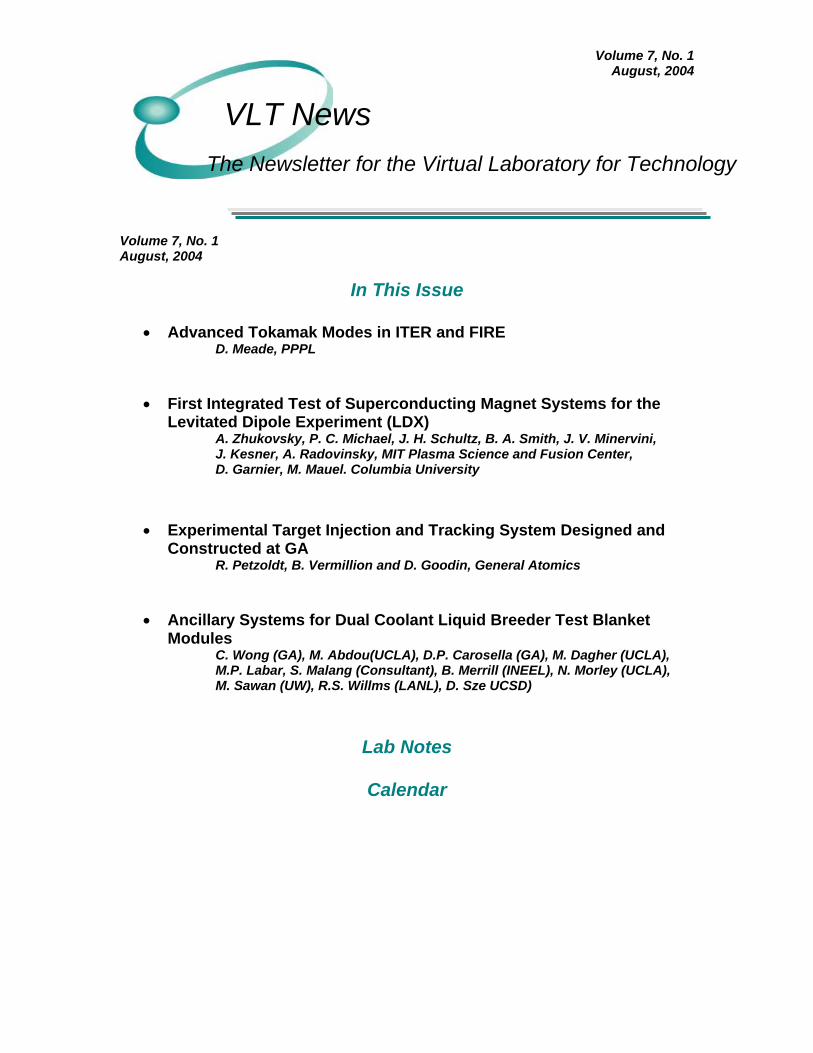
steady state, high beta plasma in a dipole magnetic field. The experiment is based on the superconducting solenoid levitated inside a large vacuum chamber to maximize magnetic flux expansion. Fig. 1 shows the LDX arrangement. An overview of the experiment and the magnet system [1,2] and details of magnets including F-coil [3,4], C-coil [5], and L-coil [6] have been published. This article describes the first inductive charging of the F-coil. The floating coil (F-
coil) levitates without any connection extending through the plasma volume. The F-coil is charged/discharged inductively when it is located in the charging station (CS) attached to the bottom of the LDX vacuum chamber. A mechanical launcher brings the F-coil to the center of the vacuum chamber and back. The F-coil remains superconductive with a near constant operating current for several hours per experimental run.
LAUNCHER
L-COIL
VACUUMCHAMBER
F-COIL IN LDXAT OPERATION
LAUNCHER
F-COIL IN CHARGING STATION
C-COIL
Fig. 1. LDX installation. The sequence of operation is as follows. The C-coil is charged when the F-coil conductor is in the normal state. Then the F-coil is cooled to about 5 K and it is charged inductively by the C-coil discharge. At the end of operation the F-coil is discharged by the C-coil charge. Then F-coil is warmed by a flow of warm helium above its superconductive state. Finally the C-coil is discharged. The C-coil was designed, built and tested by Efremov Institute, St. Petersburg, Russia. The critical current of the coil immersed in LHe was determined as 440 A. The 8 ton C-coil was delivered by sea and then by a track to MIT, Cambridge. The C-coil with the CS in its bore was moved below the LDX
vacuum chamber. The CS was bolted to the LDX vacuum chamber. Then the C-coil was centered with respect to the CS and fixed at the permanent supports. During the acceptance tests at MIT the C-coil without a quench was energized at 0.36 A/s to 400 A. Floating coil and charging station The F-coil (OD/ID of 764/526 mm, 720 turns) was wound at Everson Electric Co. (now Everson-Tesla) on a stainless steel form using about 1500 m of pre-reacted Nb3Sn Rutherford cable soldered into a copper channel. Three copper rings are built into the coil and epoxy impregnated with the winding for a more uniform heating of the coil during a quench. After manufacturing

Volume 6, No. 2 November, 2003
the coil was tested during a current driven test at MIT in a liquid helium cryostat. The coil was charged at 12.5 A/s to 2200 A without a quench. Then the 800 mm long lap joint was fabricated at the coil OD. An epoxy impregnated fiberglass tape reinforced the coil and the joint. The finished coil was then transferred to Ability Engineering, where its cryostat was manufactured. The coil is installed inside of a toroidal, Inconel 625 helium vessel. The vessel is designed to store about 1.2 kg of helium at room temperature and 12.5 MPa to supplement the magnet's heat capacity during operation between 5 and 10 K, at which the helium pressure drops to 0.14-0.35 MPa. A high heat capacity fiberglass-lead composite radiation shield surrounds the helium vessel with about a 5 mm gap. Eight 12 mm Pyrex glass balls support the shield at the vessel. The shield is wrapped with a multi-layer insulation. Then the magnet and shield assembly is installed in a vacuum shell made of two halves. The helium vessel is supported in the vacuum shell by 8 sets of top, bottom, and side supports comprised of 0.1 mm thick laminated cold rolled steel washers. Installed in eight frames the stacks are thermally anchored to the shield, and designed to withstand an impact load of 50 kN each in case of levitating failure. The full mass of the F-coil is 550 kg (400 kg - helium vessel with magnet, 60 kg - shield, 90 kg - vacuum shell).
A tube heat exchanger serves to cool first the coil, then the He gas in the vessel, and finally the shield. The heat exchanger inlet and outlet ports as well as the instrument connector are located at the bottom of the cryostat. The pump-out port and the high-pressure helium fill port are installed in the upper part of the cryostat. Eight Cernox RTD thermometers measure temperatures of the helium vessel wall, radiation shield, and heat exchanger inlet and outlet. The F-coil charging station (CS) was also made at Ability Engineering. It is a 1157 mm diameter, about 1 m tall steel cylinder bolted to the bottom flange of the LDX chamber. The CS bottom plate has holes for F-coil feedthroughs, the launcher, for diagnostics. A rotating ring supports and centers the F-coil inside of the CS. A CS stopper limits the azimuthal rotation of the F-coil. Once the F-coil is aligned, the transfer lines and the instrument connector are engaged into the F-coil ports from below the CS. The support ring is installed on four load cells to measure vertical forces between F- and C-coils during charging. Four other load cells measure horizontal forces. An intricate system of retractable guard tubes, pump-out ports, valves and pumping lines is built below the CS. This system is used for connecting and retracting the helium transfer lines without spoiling vacuum in the LDX chamber, pumping out, and plugging the F-coil heat exchanger before launch, and for other operations.
Inductive charging of the F-coil The F-coil was cooled several times outside of the vacuum chamber by liquid nitrogen and then by liquid helium. These cryogenic tests indicated that the F-coil top and bottom supports were the sources of an excessive heat load. Cold spots were detected at the shell surface near the supports, particularly the ones near the top. We believe that this heat conducts through the laminated stacks due to an excessive vertical compression of top and bottom supports which occured during assembly and consecutive welding of the shell halves. No other cold spots were found on the shell surface including areas
near side supports. Cooling of the helium vessel by LN2 flow to about 80 K took 100-120 hours. Cooling by LHe to about 4.5K took 6.3 hours at a LHe consumption of 110 liters. At the end of cooling the minimum helium vessel temperature was maintained 4.4-4.7 K at a LHe flow rate of about 40 l/h. The bottom of the helium vessel was always colder than its top. After these cryogenic tests the F-coil was installed inside the CS of LDX. All mechanisms of the CS were checked and adjusted. The LDX vacuum chamber was pumped out to about 5x10⁻⁵ Torr. The F-coil
Volume 6, No. 2 November, 2003
was cooled by a flow of LN2 and then by LHe through the heat exchanger. Simultaneously the C-coil was cooled down and filled with LHe. The C-coil quench detection system was calibrated during several ramps at currents below 50 A. When the temperature of the F-coil helium vessel was close to 30-35 K the C-coil was charged to 100 A. When the temperature of the
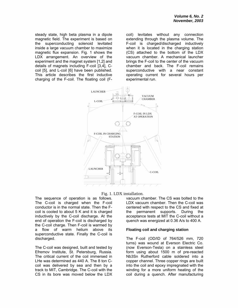
helium vessel dropped to 4.6-5.7 K we began to discharge the C-coil charging the F-coil finally to about 430 A. About 20 min after charging of the F-coil LHe cooling was terminated and the coil was left to warm through its heat leak. The F-coil quenched 2h15min after termination of cooling. The full consumption of LHe was 133 liters.
0
5
10
15
20
25
30
35
-30 0 30 60 90 120
Time (min)
Tem
pera
ture
(K)
1- Inlet2- He Vess_top3- He Vess_bot4- Shield ID5- Shield OD
1
2
3
4
5
4,5
1
2
3
He shutoff at Time=0
Fig. 2. Temperatures of the F-coil charged to about 1080 A and warmed till quench.
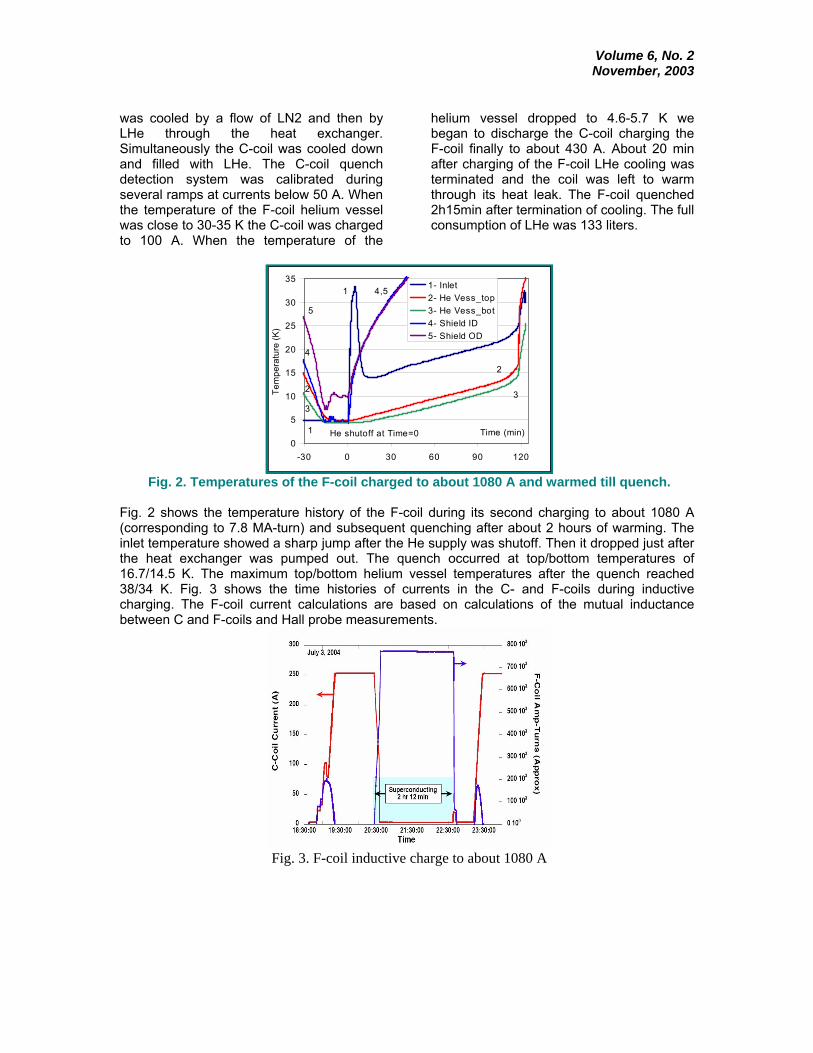
Fig. 2 shows the temperature history of the F-coil during its second charging to about 1080 A (corresponding to 7.8 MA-turn) and subsequent quenching after about 2 hours of warming. The inlet temperature showed a sharp jump after the He supply was shutoff. Then it dropped just after the heat exchanger was pumped out. The quench occurred at top/bottom temperatures of 16.7/14.5 K. The maximum top/bottom helium vessel temperatures after the quench reached 38/34 K. Fig. 3 shows the time histories of currents in the C- and F-coils during inductive charging. The F-coil current calculations are based on calculations of the mutual inductance between C and F-coils and Hall probe measurements.
Fig. 3. F-coil inductive charge to about 1080 A
Volume 6, No. 2 November, 2003
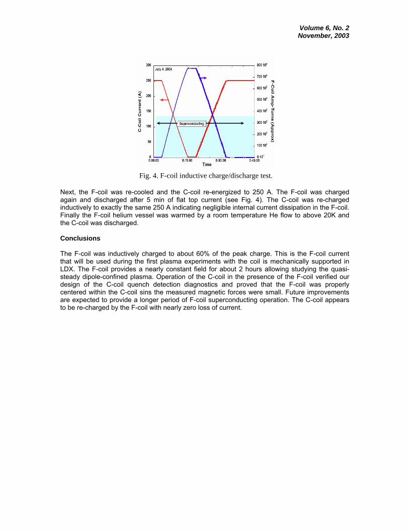
Fig. 4. F-coil inductive charge/discharge test.
Next, the F-coil was re-cooled and the C-coil re-energized to 250 A. The F-coil was charged again and discharged after 5 min of flat top current (see Fig. 4). The C-coil was re-charged inductively to exactly the same 250 A indicating negligible internal current dissipation in the F-coil. Finally the F-coil helium vessel was warmed by a room temperature He flow to above 20K and the C-coil was discharged. Conclusions The F-coil was inductively charged to about 60% of the peak charge. This is the F-coil current that will be used during the first plasma experiments with the coil is mechanically supported in LDX. The F-coil provides a nearly constant field for about 2 hours allowing studying the quasi-steady dipole-confined plasma. Operation of the C-coil in the presence of the F-coil verified our design of the C-coil quench detection diagnostics and proved that the F-coil was properly centered within the C-coil sins the measured magnetic forces were small. Future improvements are expected to provide a longer period of F-coil superconducting operation. The C-coil appears to be re-charged by the F-coil with nearly zero loss of current.

Volume 6, No. 2 November, 2003
Acknowledgments This work was funded by the U.S. Department of Energy under the Grant DE-FG02-98ER-54428. We thank R. Lations and D. Strahan for their technical assistance.
References [1] J. Kesner, L. Bromberg, D. Garnier, M. Mauel, Plasma confinement in a magnetic dipole, IAEA Fusion Eng. Congress 1998, 3 (1999) 1165-1168. [2] J. Shultz et al, The levitated dipole experiment magnet system, IEEE Trans. Appl. Supercond, 9 (1999) 378-381. [3] A. Zhukovsky et al, Design and fabrication of the cryostat for the floating coil of the LDX, IEEE Trans. Appl. Supercond, 10 (2000) 1522-1525. [4] A. Zhukovsky et al, Status of the floating coil of the levitated dipole experiment, IEEE Trans. Appl. Supercond, 12 (2002) 666-669. [5] A. Zhukovsky et al, Charging magnet for the F-coil of LDX, IEEE Trans. Appl. Supercond, 11 (2001) 1873-1876. [6] P. Michael et al, Performance of the conduction cooled LDX levitation coil, Adv. in Cryogenic Eng., 49A (2004) 701-710.
Contributed by: A. Zhukovsky, P. C. Michael, J. H. Schultz, B. A. Smith, J. V. Minervini, J. Kesner, A. Radovinsky, MIT Plasma Science and Fusion Center; D. Garnier, M. Mauel. Columbia University
Volume 6, No. 2 November, 2003
Experimental Target Injection and Tracking System Designed and Constructed at GA
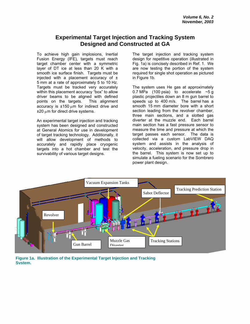
To achieve high gain implosions, Inertial Fusion Energy (IFE), targets must reach target chamber center with a symmetric layer of DT ice at less than 20 K with a smooth ice surface finish. Targets must be injected with a placement accuracy of ± 5 mm at a rate of approximately 5 to 10 Hz. Targets must be tracked very accurately within this placement accuracy “box” to allow driver beams to be aligned with defined points on the targets. This alignment accuracy is ±150 µm for indirect drive and ±20 µm for direct drive systems. An experimental target injection and tracking system has been designed and constructed at General Atomics for use in development of target tracking technology. Additionally, it will allow development of methods to accurately and rapidly place cryogenic targets into a hot chamber and test the survivability of various target designs.
The target injection and tracking system design for repetitive operation (illustrated in Fig. 1a) is concisely described in Ref. 1. We are now testing the portion of the system required for single shot operation as pictured in Figure 1b. The system uses He gas at approximately 0.7 MPa (100 psia) to accelerate ~5 g plastic projectiles down an 8 m gun barrel to speeds up to 400 m/s. The barrel has a smooth 15 mm diameter bore with a short section leading from the revolver chamber, three main sections, and a slotted gas diverter at the muzzle end. Each barrel main section has a fast pressure sensor to measure the time and pressure at which the target passes each sensor. The data is collected via a custom LabVIEW DAQ system and assists in the analysis of velocity, acceleration, and pressure drop in the barrel. This system is now set up to simulate a fueling scenario for the Sombrero power plant design.
Figure 1a. Illustration of the Experimental Target Injection and Tracking System.
Revolver
Gun Barrel
Vacuum Expansion Tanks
Muzzle GasDiverter
Tracking Stations
Sabot Deflector Tracking Prediction Station

Volume 6, No. 2 November, 2003
Figure 1b. The Experimental Target Injection andTracking System, full length ~ 30 meters.
Direct drive targets are protected from heating and mechanical damage in the gun barrel by placing them in sabots (Fig. 2). A pin in the loading system chamber keeps the sabot spring compressed prior to target acceleration. The inertia of the leading half of the sabot keeps the spring compressed during acceleration. Once the target leaves the end of the gun barrel, the spring forces the two halves of the sabot
apart and away from the target. The sabot then is diverted from its trajectory by the sabot deflector, which has an angled rod that extends slightly into the sabots path, but not into the target’s smaller-diameter path. High-intensity light sources and a high-speed digital CMOS video camera have been installed (Fig. 3) to photograph sabot deflection (Fig. 4). Position detectors (Fig. 5) use laser light sources with photodiodes and line scan cameras to accurately measure the timing and position of passing targets. Data from position measurements early in the target’s trajectory are used to accurately predict the time and position that the targets will pass a final position detector. The target tracking system design is discussed fully in Ref. 2.
.
Figure 2. Spring-loaded sabot protects the target from the barrel and gas heating during acceleration
Figure 3. Sabot deflector with light sources and camera.
Volume 6, No. 2 November, 2003
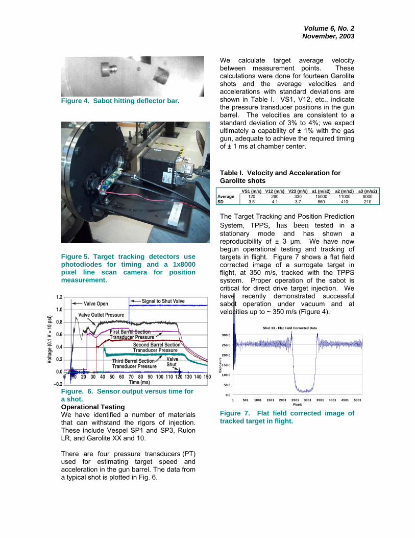
Figure 4. Sabot hitting deflector bar.
Figure 5. Target tracking detectors use photodiodes for timing and a 1x8000 pixel line scan camera for position measurement.
Figure. 6. Sensor output versus time for a shot. Operational Testing We have identified a number of materials that can withstand the rigors of injection. These include Vespel SP1 and SP3, Rulon LR, and Garolite XX and 10. There are four pressure transducers (PT) used for estimating target speed and acceleration in the gun barrel. The data from a typical shot is plotted in Fig. 6.
We calculate target average velocity between measurement points. These calculations were done for fourteen Garolite shots and the average velocities and accelerations with standard deviations are shown in Table I. VS1, V12, etc., indicate the pressure transducer positions in the gun barrel. The velocities are consistent to a standard deviation of 3% to 4%; we expect ultimately a capability of ± 1% with the gas gun, adequate to achieve the required timing of ± 1 ms at chamber center. Table I. Velocity and Acceleration for Garolite shots
The Target Tracking and Position Prediction System, TPPS, has been tested in a stationary mode and has shown a reproducibility of ± 3 µm. We have now begun operational testing and tracking of targets in flight. Figure 7 shows a flat field corrected image of a surrogate target in flight, at 350 m/s, tracked with the TPPS system. Proper operation of the sabot is critical for direct drive target injection. We have recently demonstrated successful sabot operation under vacuum and at velocities up to ~ 350 m/s (Figure 4). Figure 7. Flat field corrected image of tracked target in flight.
Valve Open
Valve Outlet Pressure
First Barrel SectionTransducer Pressure
Second Barrel SectionTransducer Pressure
Third Barrel SectionTransducer Pressure
ValveShut
Signal to Shut Valve
100–0.2
0.0
0.2
0.4
0.6
Volta
ge (0
.1 V
= 1
0 ps
i)
0.8
1.0
1.2
20 30 40 50 60 70Time (ms)
80 90 100 110 120 130 140 150
VS1 (m/s) V12 (m/s) V23 (m/s) a1 (m/s2) a2 (m/s2) a3 (m/s2)Average 120 260 330 15000 11000 8000SD 3.5 4.1 3.7 860 410 210
Shot 33 - Flat Field Corrected Data
0.0
50.0
100.0
150.0
200.0
250.0
300.0
1 501 1001 1501 2001 2501 3001 3501 4001 4501 5001Pixels
Expo
sure

Volume 6, No. 2 November, 2003
Summary and Conclusions The Experimental Target and Injection Tracking System is operational and we are beginning to achieve our experimental goals. We have identified and tested sabot materials capable of withstanding the rigors of the injection system while not inducing wear in the gun barrel. We have achieved successful sabot separation with surrogate direct drive targets, and we are achieving consistent (< 3-4% variation) velocities of ~ 350 m/s. Initial tests have resulted in approximately 50% of our surrogate targets within the placement accuracy requirement of ± 5 mm. Our next steps are to improve placement accuracy via gas turbulence mitigation, enhanced sabot design, and refinements in the crown and muzzle of the gas gun. We are also preparing the system for “rep-rated” (6 Hz) operations, to demonstrate repetitive target injection accuracy for IFE power plant fueling.
Acknowledgement Work supported by Naval Research Laboratory under Subcontract N00173-02-C-6007 and the U.S. Department of Energy under Contract No. DE-AC03-98-ER-54411. References R.W. PETZOLDT, N.B. ALEXANDER, T.J. DRAKE, D.T. GOODIN, K. JONESTRASK, and R.W. STEMKE, “Experimental Target Injection and Tracking System,” Fusion Technology (July 2003). R.W. PETZOLDT, M. CHERRY, N.B ALEXANDER, D.T. GOODIN, G.E. BESENBRUCH, and K.R. SCHULTZ, “Design of an Inertial Fusion Energy Target Tracking and Position Prediction System,” Fusion Technology, 39, No. 2 678 (2001). Contributed by Ron Petzoldt, Brian Vermillion and Dan Goodin, General Atomics
Ancillary Systems for Dual Coolant Liquid Breeder Test Blanket Modules
In recent months while ITER is deciding on its site, the Test Blanket Working Group (TBWG) has been very active. All ITER parties have been trying to provide to TBWG the required information regarding the interfaces between their respective Test Blanket Module (TBM) design and the external loop systems for heat extraction, coolant circulation, tritium extraction and coolant purification, as well as requirements for all additional ancillary systems. For the US, one of our interests has been in the development of dual coolant (DC) liquid breeder first wall (FW) and blanket concepts, which have the potential of high thermal efficiency even with the use of ferritic steel (FS) (Tmax-limit ≤ 550° C) as the structural material. Helium is selected as the FW and blanket structure coolant with either Pb-17Li or a low melting point molten
salt (MS) as liquid breeder/coolant in the blanket. This approach of TBM development leads to our requirement that the defined ancillary equipment spatial envelope and supporting equipments will have to be able to cover the cases for DC Pb-17Li and DC MS concepts. As an example for our assessment LiBeF3 is selected as our low melting point MS option. Equipment size is designed to the maximum power handling of surface heat flux of 0.5 MW/m2 and a neutron wall loading of 0.78 MW/m2 for half of an ITER test port. Based on the requirements of handling the first wall heat flux and maximizing the outlet temperature of the liquid breeder coolant up to 650°C, which is thermally insulated from the FS structure, we have to evaluate the ancillary equipment required for two coolant loops.
Volume 6, No. 2 November, 2003
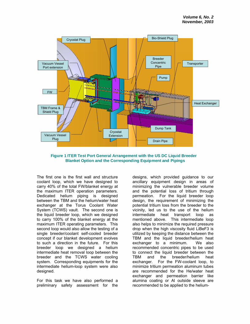
The first one is the first wall and structure coolant loop, which we have designed to carry 40% of the total FW/blanket energy at the maximum ITER operation parameters. Dedicated helium piping is designed between the TBM and the helium/water heat exchanger at the Torus Coolant Water System (TCWS) vault. The second one is the liquid breeder loop, which we designed to carry 100% of the blanket energy at the maximum ITER operating parameters. This second loop would also allow the testing of a single breeder/coolant self-cooled breeder concept if our blanket development evolves to such a direction in the future. For this breeder loop we designed a helium intermediate heat removal loop between the breeder and the TCWS water cooling system. Corresponding equipments for the intermediate helium-loop system were also designed. For this task we have also performed a preliminary safety assessment for the
designs, which provided guidance to our ancillary equipment design in areas of minimizing the vulnerable breeder volume and the potential loss of tritium through permeation. For the liquid breeder loop design, the requirement of minimizing the potential tritium loss from the breeder to the vicinity, led us to the use of the helium intermediate heat transport loop as mentioned above. This intermediate loop also helps to minimize the required pressure drop when the high viscosity fluid LiBeF3 is utilized by keeping the distance between the TBM and the liquid breeder/helium heat exchanger to a minimum. We also recommended concentric pipes to be used to connect the liquid breeder between the TBM and the breeder/helium heat exchanger. For the FW-coolant loop, to minimize tritium permeation aluminum tubes are recommended for the He/water heat exchanger and permeation barrier like alumina coating or Al outside sleeve are recommended to be applied to the helium-
Vacuum VesselPort extension
Bio-Shield PlugCryostat Plug
Transporter
Vacuum VesselPlug
CryostatExtension
TBM Frame &Shield Plug
BreederConcentric
Pipe
FW
Drain Pipe
Pump
Dump Tank
Heat Exchanger
Figure 1 ITER Test Port General Arrangement with the US DC Liquid Breeder Blanket Option and the Corresponding Equipment and Pipings
Volume 6, No. 2 November, 2003
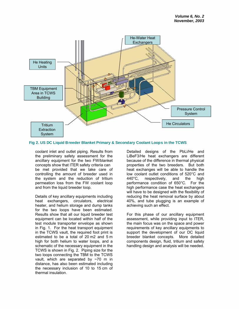
coolant inlet and outlet piping. Results from the preliminary safety assessment for the ancillary equipment for the two FW/blanket concepts show that ITER safety criteria can be met provided that we take care of controlling the amount of breeder used in the system and the reduction of tritium permeation loss from the FW coolant loop and from the liquid breeder loop. Details of key ancillary equipments including heat exchangers, circulators, electrical heater, and helium storage and dump tanks for the two loops have been estimated. Results show that all our liquid breeder test equipment can be located within half of the test module transporter envelope as shown in Fig. 1. For the heat transport equipment in the TCWS vault, the required foot print is estimated to be a total of 20 m2 and 5 m high for both helium to water loops, and a schematic of the necessary equipment in the TCWS is shown in Fig. 2. Piping size for the two loops connecting the TBM to the TCWS vault, which are separated by ~70 m in distance, has also been estimated including the necessary inclusion of 10 to 15 cm of thermal insulation.
Detailed designs of the PbLi/He and LiBeF3/He heat exchangers are different because of the difference in thermal physical properties of the two breeders. But both heat exchanges will be able to handle the low coolant outlet conditions of 520°C and 440°C, respectively, and the high performance condition of 650°C. For the high performance case the heat exchangers will have to be designed with the flexibility of reducing the heat removal surface by about 40%, and tube plugging is an example of achieving such an effect. For this phase of our ancillary equipment assessment, while providing input to ITER, the main focus was on the space and power requirements of key ancillary equipments to support the development of our DC liquid breeder blanket concepts. More detailed components design, fluid, tritium and safety handling design and analysis will be needed.
Fig 2. US DC Liquid Breeder Blanket Primary & Secondary Coolant Loops in the TCWS
TritiumExtractionSystem
He Circulators
He HeatingUnits
He-Water HeatExchangers
TBM EquipmentArea in TCWS
Building
Pressure ControlSystem
Volume 6, No. 2 November, 2003
The scenario of testing FW/blanket concepts in difference phases of ITER operation will have to be developed and the corresponding sequence of installing necessary testing components will have to be coordinated. But the requested envelope for the two testing loops proposed in this report will be able to provide the flexibility of testing the
selected DC liquid breeder FW/blanket concepts. Contributed by C. Wong (GA), M. Abdou (UCLA), D. Carosella (GA), M. Dagher (UCLA), M. Labar (GA), S. Malang (Consultant), B. Merrill (INEEL), N. B. Morley (UCLA), M. Sawan (UW), R.S. Willms (LANL), Dai-Kai Sze (UCSD

Volume 6, No. 2 November, 2003
Insert Dale Meade article here Charles Baker to Retire from UCSD – Will Continue as VLT Director
Dr. Charles C. Baker, Director of the U.S. fusion program's Virtual Laboratory for Technology, will retire from the University of California at San Diego (UCSD) effective August 13. He will retain his appointment as an adjunct professor at UCSD and thus plans to keep some ties to the university. He will move to the Albuquerque, New Mexico area. in mid-August. He will continue in the role as director of the Virtual Laboratory for Technology and continue serving on the DOE's Fusion Energy Sciences Advisory Committee (FESAC). Thus, his national fusion responsibilities will be largely unchanged. He will do this as part-time work under a personal services contract with the Sandia National Laboratories (SNL) in Albuquerque and will have an office at SNL.
DOE to Improve Science and Technology Education through STARS Initiative To help foster the next generation of American scientists and engineers, the Department of Energy (DOE) announced the Scientists Teaching and Reaching Students (STARS) initiative involving both students and teachers in grades K-12. Spencer Abraham, Secretary of Energy, outlined the STARS initiative, launched by DOE and its national laboratories, earlier this month at the Stanford Linear Accelerator Center in Paolo Alto, Calif. The STARS initiative will work to fill the deficiency occurring during the middle school years by incorporating several programs intended to pique students’ interest in math and science careers. The initiative consists of seven steps: • Host Science Appreciation Days at the national laboratories throughout the year, offering activities and resources to 2,000 fifth- and eighth-graders and exposing them
to a broad range of possibilities in science fields; • Create the Office of DOE Science Education to coordinate all education outreach for DOE and explore ways to expand the leveraging of resources at the national laboratories by forging partnerships with federal and nongovernmental agencies; • Upgrade and promote the “Ask a Scientist” website, which provides a forum for basic and complex science questions screened by teachers and answered by scientists; • Establish the Science Teacher Professional Development Program, in which 77 K-14 teachers are provided mentor-intensive science experiences to improve their knowledge and technical expertise in science and math. The three-year program will begin this summer and take place for 4-8 weeks at seven national laboratories.
Lab Notes
QuickTime™ and aTIFF (Uncompressed) decompressor
are needed to see this picture.
Dr. Baker
Volume 6, No. 2 November, 2003
• Develop Career Day programs at the national laboratories to invite local schools and communities to attend open houses or seminars in science and technology, presented by scientists working at the labs in order to explore different career paths in science and math; • Host a yearly “What’s Next?” Expo to bring together scientists and corporate innovators to demonstrate breakthrough science technologies they expect to become commonplace in the future; and,
• Promote Science Superstars, a program to introduce teachers, students, and education professionals to internationally recognized, award-winning scientists and Nobel Laureates in order to inspire young scientists to continue their studies in the field. The Secretary of Energy Task Advisory Board will solicit input from scientists, mathematicians, education specialists, business leaders, and teachers and report their findings and recommendations to Abraham by the end of the year.
Editor’s Note: The VLT News will continue to accept submissions for articles through the UCSD office. Please read the information below for instructions on how to submit your article for publication.
The submission of articles to this publication is encouraged. Please submit your articles electronically, in a Mac or PC-compatible format, preferably in Microsoft Word. The VLT Director reserves the right to edit articles for content. This publication is a not-for-profit endeavor and relevant copyright rules and regulations regarding publishing rights will apply.
Submit articles and news notes via e-mail to: Pat Stewart : [email protected]
Editor, VLT News or
Dr. Charles C. Baker: [email protected] Director, Virtual Laboratory for Technology
Our mailing address is:
Virtual Laboratory for Technology University of California, San Diego
9500 Gilman Drive, Engineering Building II, L-309 La Jolla, CA 92093-0420
Ph: 619-534-4971
Volume 6, No. 2 November, 2003
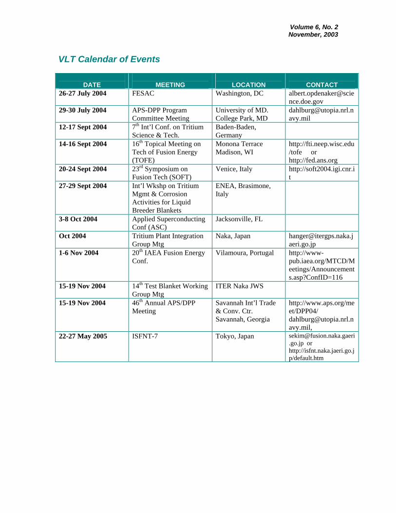
VLT Calendar of Events
DATE
MEETING
LOCATION
CONTACT
26-27 July 2004 FESAC Washington, DC [email protected]
29-30 July 2004 APS-DPP Program Committee Meeting
University of MD. College Park, MD
12-17 Sept 2004 7th Int’l Conf. on Tritium Science & Tech.
Baden-Baden, Germany
14-16 Sept 2004 16th Topical Meeting on Tech of Fusion Energy (TOFE)
Monona Terrace Madison, WI
http://fti.neep.wisc.edu/tofe or http://fed.ans.org
20-24 Sept 2004 23rd Symposium on Fusion Tech (SOFT)
Venice, Italy http://soft2004.igi.cnr.it
27-29 Sept 2004 Int’l Wkshp on Tritium Mgmt & Corrosion Activities for Liquid Breeder Blankets
ENEA, Brasimone, Italy
3-8 Oct 2004 Applied Superconducting Conf (ASC)
Jacksonville, FL
Oct 2004 Tritium Plant Integration Group Mtg
Naka, Japan [email protected]
1-6 Nov 2004 20th IAEA Fusion Energy Conf.
Vilamoura, Portugal http://www-pub.iaea.org/MTCD/Meetings/Announcements.asp?ConfID=116
15-19 Nov 2004 14th Test Blanket Working Group Mtg
ITER Naka JWS
15-19 Nov 2004 46th Annual APS/DPP Meeting
Savannah Int’l Trade & Conv. Ctr. Savannah, Georgia
http://www.aps.org/meet/DPP04/ [email protected],
22-27 May 2005 ISFNT-7 Tokyo, Japan [email protected] or http://isfnt.naka.jaeri.go.jp/default.htm

Volume 6, No. 2 November, 2003