vol. 5, issue 4, april 2016 heat transfer intensification ... · pdf fileheat transfer...
TRANSCRIPT
ISSN(Online): 2319-8753
ISSN (Print): 2347-6710
International Journal of Innovative Research in Science,
Engineering and Technology (A High Impact Factor, Monthly Peer Reviewed Journal)
Vol. 5, Issue 4, April 2016
Copyright to IJIRSET DOI:10.15680/IJIRSET.2015.0502001 1333
Heat Transfer Intensification in U-bend
Double Pipe Heat Exchanger using Twisted
Tape Inserts
L.Sandeep Raj1, K.Vijaya Kumar Reddy
2, A.Aruna Kumari
2
Assitant Professor, VNR Vignana Jyothi Institute of Engineering and Technology, Hyderabad, India1
Professor, JNTUH College of Engineering Hyderabad, India2
Abstract: Generating a swirl flow in the flow field is widely employed passive heat transfer augmentation or
intensification technique. In present work, twisted tapes are inserted into the inner pipe side of Counter flow U-bend
Double Pipe Heat Exchanger for creating a swirl flow and thus Enhancing the Heat Transfer. Twisted tapes of different
twist ratios (H/D) 5,10,15,20 and strip insert (i.e without any twist) are employed to enhance the Heat Transfer.
Turbulent swirl flow with forced convection is considered for experimental study. For different twist ratios, mass flow
rate of cold fluid in inner pipe side is varied, by maintaining the constant mass flow rate in the annulus side.
Experimental data is validated using available correlations. The results show that, for mass flow rate of 8 LPM the
enhancement in Heat Transfer is 55.69% compared with that of plain tube and corresponding Pressure Drop is only
20%.
Keywords: Heat Transfer Intensification, Heat Transfer Enhancement, U-bend Double Pipe Heat Exchanger, Inserts,
Twisted Tapes.
I. INTRODUCTION
Heat Transfer is unavoidable process that nature has gifted to Humankind. In engineering applications wherever
energy conversion is involved, Heat transfer finds a great importance. Heat Transfer Enhancement or Intensification
aims at increasing the rate at which Heat transfers from one body to another or from one medium to another. Improved
Heat Exchange over and above the usual and standard practice can significantly improve thermal efficiency in such
engineering applications as well as the economics of their design and operation can be optimised [1]. This fact gives lot
of scope for Research in this area of Heat Transfer Enhancement.
S.S. Hsieh, I.W. Huang[2] investigated Heat Transfer Enhancement in Laminar Flow with Longitudinal inserts. For
these inserts, Thermal Entry Length was found and it is correlated with in terms of Reynolds Number. Based on same
hydraulic Diameter, Enhancement of Heat Transfer compared to bare tube was found to be 16 times more at Reynolds
Number less than 400, while Friction Factor rise is just 4.5 times.
S. K. Saha, A. Dutta[3] observed that for higher twists, twisted tapes of short length are performing better than full
length twisted tapes. Lower values of Nusselt Number and Friction Factor are obtained for short length twisted tapes
compared with full length counter parts.
Under Uniform Wall Heat Flux boundary condition, S. K. Saha, P. Langille[4] conducted experimental and
theoretical studies on Laminar flow through a circular tube. For short length strips & regularly spaced strip elements,
Friction Factor & Nusselt Number are less in comparison with the full length elements
Anil Singh Yadav[5] found that heat transfer coefficient is found to increase by 40% with half-length twisted tape
inserts when compared with plain heat exchanger. It was found that on the basis of equal mass flow rate, the heat

ISSN(Online): 2319-8753
ISSN (Print): 2347-6710
International Journal of Innovative Research in Science,
Engineering and Technology (A High Impact Factor, Monthly Peer Reviewed Journal)
Vol. 5, Issue 4, April 2016
Copyright to IJIRSET DOI:10.15680/IJIRSET.2015.0502001 1334
transfer performance of half-length twisted tape is better than plain heat exchanger, and on the basis of unit pressure
drop the heat transfer performance of smooth tube is better than half-length twisted tape.
P. V. Durga Prasad, A. V. S. S. K. S. Gupta[6] reported that on equal mass flow rate basis, Heat Transfer
performance is enhanced with twisted tapes . Whereas, on unit pressure drop basis, Heat Transfer performance is better
on smooth tube compared with twisted tapes. They also reported significant increase in heat transfer coefficient,
friction factor, and found that the thermal Performance of smooth tube is better than the full length twisted tape by 2.0–
2.2 times.
Based on experimental flow visualization and computational modelling of single-phase laminar flows, Raj M.
Manglik, Arthur E. Bergles[7] considered a fundamental scaling of the cross-sectional vortex structure and a parametric
analysis of the primary enhancement mechanisms in single-phase flows are delineated.
B. V. N. Ramakumar, J. D. Arsha, Praveen Tayal[8] employed Tapered Twisted Tape Inserts for Enhancing Heat
Transfer. They performed simulations using ANSYS FLUENT 14.0. They reported that overall enhancement ratio is
greater than that of classical twisted tapes under all Reynolds Number Studied. An increase of 17% in overall
enhancement is predicted with taper angle of 0.5.
S.N. Sarada, A.V.S.R. Raju and K.K. Radha[9] conducted experimental and theoretical studies on turbulent flow
heat transfer enhancement in a horizontal circular tube using mesh inserts. They reported an increase of Nusselt number
2.15 times and pressure drop of only 1.23 times compared to that of plain tube.
P.Murugesan, K.Mayilsamy, S.Suresh[10] investigated Heat Transfer Enhancement using square cut twisted tapes
with three twist ratios 2.0, 4.4, 6.0. Over the range considered, the Nusselt number is 1.03 to 1.14 times, friction factor
is 1.05 to 1.25 times and thermal enhancement factor is 1.02 to 1.06 times in a tube with Square cut Twisted Tape of
those in tube with Plain Twisted Tapes.
Twin counter twisted tapes and twin co-twisted tapes are employed by S. Eiamsa-ard, C. Thianpong, P. Eiamsa-
ard[11] for generating counter swirl flow and co-swirl flow respectively. They reported that Twin counter twisted tapes
improve Heat Transfer around 12.5–44.5% and 17.8–50% higher than those with the twin co-twisted tapes and single
twisted tape, respectively.
S. V. Patil & P. V. Vijay Babu[12] employed twisted tapes in square Duct and Circular Tube. Working Fluid is
Ehylene Glycol. Based on constant flow rate and constant pumping power criteria, Nusselt numbers were found to be
5.44–7.49 and 2.46–4.87 times that of plain square duct forced convection values respectively.
Numerical Simulation Studies are conducted by Sami D. Salman, Abdul Amir H. Kadhum, Mohd S. Takriff, Abu
Bakar Mohamad[13] on Circular Tube Fitted with Alternative Axis Twisted Tape under a Constant Heat Flux. Among
the various twist ratios and alternative angles, the twist ratio of y = 2.93 and alternative angle β = 90° offered a
maximum heat transfer enhancement.
II. EXPERIMENTAL SETUP AND PROCEDURE
2.1 Description of Experimental Setup:
The Counter Flow U-bend Double Pipe Heat Exchanger considered for this Experimental study consists of two
essential parts
1. Inner Pipe of Inner Diameter(di) =19mm, Outer Diameter (d0) = 25mm
2. Outer Pipe of Inner Diameter (Di) = 50mm, Outer Diameter (Do) = 56mm
Both these Pipes are mounted concentrically as shown in the Figure 1.
Outer pipe is insulated using an asbestos sheet throughout its length. Inner pipe which is not covered by annulus is
also insulated with asbestos sheet.
ISSN(Online): 2319-8753
ISSN (Print): 2347-6710
International Journal of Innovative Research in Science,
Engineering and Technology (A High Impact Factor, Monthly Peer Reviewed Journal)
Vol. 5, Issue 4, April 2016
Copyright to IJIRSET DOI:10.15680/IJIRSET.2015.0502001 1335
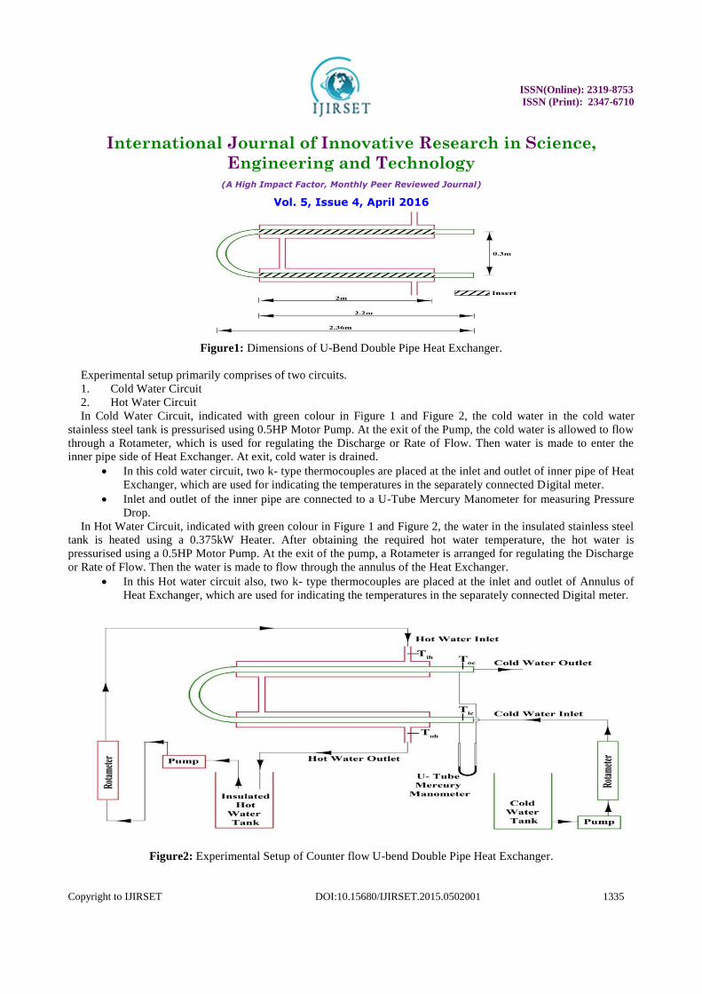
Figure1: Dimensions of U-Bend Double Pipe Heat Exchanger.
Experimental setup primarily comprises of two circuits.
1. Cold Water Circuit
2. Hot Water Circuit
In Cold Water Circuit, indicated with green colour in Figure 1 and Figure 2, the cold water in the cold water
stainless steel tank is pressurised using 0.5HP Motor Pump. At the exit of the Pump, the cold water is allowed to flow
through a Rotameter, which is used for regulating the Discharge or Rate of Flow. Then water is made to enter the
inner pipe side of Heat Exchanger. At exit, cold water is drained.
In this cold water circuit, two k- type thermocouples are placed at the inlet and outlet of inner pipe of Heat
Exchanger, which are used for indicating the temperatures in the separately connected Digital meter.
Inlet and outlet of the inner pipe are connected to a U-Tube Mercury Manometer for measuring Pressure
Drop.
In Hot Water Circuit, indicated with green colour in Figure 1 and Figure 2, the water in the insulated stainless steel
tank is heated using a 0.375kW Heater. After obtaining the required hot water temperature, the hot water is
pressurised using a 0.5HP Motor Pump. At the exit of the pump, a Rotameter is arranged for regulating the Discharge
or Rate of Flow. Then the water is made to flow through the annulus of the Heat Exchanger.
In this Hot water circuit also, two k- type thermocouples are placed at the inlet and outlet of Annulus of
Heat Exchanger, which are used for indicating the temperatures in the separately connected Digital meter.
Figure2: Experimental Setup of Counter flow U-bend Double Pipe Heat Exchanger.
ISSN(Online): 2319-8753
ISSN (Print): 2347-6710
International Journal of Innovative Research in Science,
Engineering and Technology (A High Impact Factor, Monthly Peer Reviewed Journal)
Vol. 5, Issue 4, April 2016
Copyright to IJIRSET DOI:10.15680/IJIRSET.2015.0502001 1336
2.2 Twisted Tape Geometry:
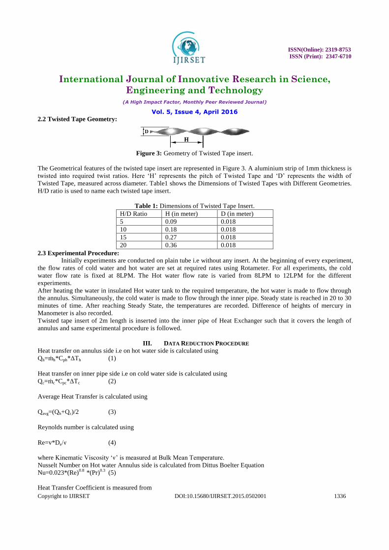
Figure 3: Geometry of Twisted Tape insert.
The Geometrical features of the twisted tape insert are represented in Figure 3. A aluminium strip of 1mm thickness is
twisted into required twist ratios. Here ‘H’ represents the pitch of Twisted Tape and ‘D’ represents the width of
Twisted Tape, measured across diameter. Table1 shows the Dimensions of Twisted Tapes with Different Geometries.
H/D ratio is used to name each twisted tape insert.
Table 1: Dimensions of Twisted Tape Insert.
H/D Ratio H (in meter) D (in meter)
5 0.09 0.018
10 0.18 0.018
15 0.27 0.018
20 0.36 0.018
2.3 Experimental Procedure:
Initially experiments are conducted on plain tube i.e without any insert. At the beginning of every experiment,
the flow rates of cold water and hot water are set at required rates using Rotameter. For all experiments, the cold
water flow rate is fixed at 8LPM. The Hot water flow rate is varied from 8LPM to 12LPM for the different
experiments.
After heating the water in insulated Hot water tank to the required temperature, the hot water is made to flow through
the annulus. Simultaneously, the cold water is made to flow through the inner pipe. Steady state is reached in 20 to 30
minutes of time. After reaching Steady State, the temperatures are recorded. Difference of heights of mercury in
Manometer is also recorded.
Twisted tape insert of 2m length is inserted into the inner pipe of Heat Exchanger such that it covers the length of
annulus and same experimental procedure is followed.
III. DATA REDUCTION PROCEDURE
Heat transfer on annulus side i.e on hot water side is calculated using
Qh=ṁh*Cph*ΔTh (1)
Heat transfer on inner pipe side i.e on cold water side is calculated using
Qc=ṁc*Cpc*ΔTc (2)
Average Heat Transfer is calculated using
Qavg=(Qh+Qc)/2 (3)
Reynolds number is calculated using
Re=v*De/ⱴ (4)
where Kinematic Viscosity ‘ⱴ’ is measured at Bulk Mean Temperature.
Nusselt Number on Hot water Annulus side is calculated from Dittus Boelter Equation
Nu=0.023*(Re)0.8
*(Pr)0.3
(5)
Heat Transfer Coefficient is measured from
ISSN(Online): 2319-8753
ISSN (Print): 2347-6710
International Journal of Innovative Research in Science,
Engineering and Technology (A High Impact Factor, Monthly Peer Reviewed Journal)
Vol. 5, Issue 4, April 2016
Copyright to IJIRSET DOI:10.15680/IJIRSET.2015.0502001 1337
hannulus=Nu*k/De (6)
where Thermal Conductivity ‘k’ is measured at Bulk Mean Temperature.
Overall Heat Transfer Coefficient is measured from
U=Qavg/(Aavg*LMTD) (7)
Experimental Heat Transfer Coefficient is measured from
hexp=1/((1/U)-(1/hannulus)) (8)
Friction Factor is Calculated from
f = (2*ΔP*Di)/(ρ*L*v2) (9)
IV. DISCUSSION ON RESULTS
4.1 Validation of Plain Tube Data:
4.1.1.Heat Transfer:
Available correlations for plain tube are
1. Dittus Boelter Equation[15]
Nu = 0.023.(Re)0.8
.(Pr)0.3
{ 0.7 ≤ Pr ≤ 160;Re > 10,000}
2. Petukhov Equation[15]
( )
( )
( )
3. Gnielinski Equation[15]
( ) ( )
( )
( )
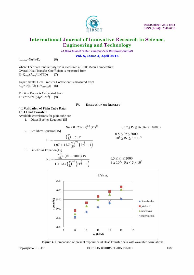
Figure 4: Comparison of present experimental Heat Transfer data with available correlations.
2000
2500
3000
3500
4000
4500
7 8 9 10 11 12 13
h (
W/m
2K
)
mc (LPM)
h Vs mc
dittus boelter
petukhov
Gnielinski
experimental
0.5 ≤ Pr ≤ 2000
104 ≤ Re ≤ 5 x 10
6
0.5 ≤ Pr ≤ 2000
3 x 10³ ≤ Re ≤ 5 x 10
6
ISSN(Online): 2319-8753
ISSN (Print): 2347-6710
International Journal of Innovative Research in Science,
Engineering and Technology (A High Impact Factor, Monthly Peer Reviewed Journal)
Vol. 5, Issue 4, April 2016
Copyright to IJIRSET DOI:10.15680/IJIRSET.2015.0502001 1338
In Figure 4, the value of h, Heat Transfer Coefficient obtained in experiment is compared with the available
correlations given by Dittus Boelter, Petukhov, Gnielinski. From this it has been observed that the experimental Heat
transfer coefficient is in agreement with available correlations.
4.1.2. Friction Factor
Available correlations for plain tube are
1. Blasius Equation[15]
2. Petukhov Equation[15]
( ( ) )
3. Simple Power Law Equation[15]
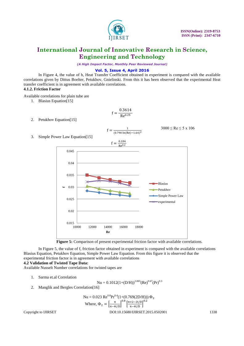
Figure 5: Comparison of present experimental friction factor with available correlations.
In Figure 5, the value of f, friction factor obtained in experiment is compared with the available correlations
Blasius Equation, Petukhov Equation, Simple Power Law Equation. From this figure it is observed that the
experimental friction factor is in agreement with available correlations
4.2 Validation of Twisted Tape Data:
Available Nusselt Number correlations for twisted tapes are
1. Sarma et.al Correlation
Nu = 0.1012(1+(D/H))2.065
(Re)0.67
(Pr)0.3
2. Manglik and Bergles Correlation[16]
Nu = 0.023 Re0.8
Pr0.4
(1+(0.769(2D/H)))
Where, [
]
[
]
0.015
0.02
0.025
0.03
0.035
0.04
0.045
10000 12000 14000 16000 18000
f
Re
Blasius
Petukhov
Simple Power Law
experimental
3000 ≤ Re ≤ 5 x 10⁶
ISSN(Online): 2319-8753
ISSN (Print): 2347-6710
International Journal of Innovative Research in Science,
Engineering and Technology (A High Impact Factor, Monthly Peer Reviewed Journal)
Vol. 5, Issue 4, April 2016
Copyright to IJIRSET DOI:10.15680/IJIRSET.2015.0502001 1339
a) H/D 5
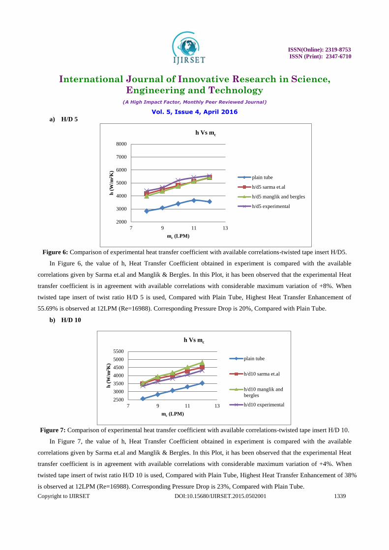
Figure 6: Comparison of experimental heat transfer coefficient with available correlations-twisted tape insert H/D5.
In Figure 6, the value of h, Heat Transfer Coefficient obtained in experiment is compared with the available
correlations given by Sarma et.al and Manglik & Bergles. In this Plot, it has been observed that the experimental Heat
transfer coefficient is in agreement with available correlations with considerable maximum variation of +8%. When
twisted tape insert of twist ratio H/D 5 is used, Compared with Plain Tube, Highest Heat Transfer Enhancement of
55.69% is observed at 12LPM (Re=16988). Corresponding Pressure Drop is 20%, Compared with Plain Tube.
b) H/D 10
Figure 7: Comparison of experimental heat transfer coefficient with available correlations-twisted tape insert H/D 10.
In Figure 7, the value of h, Heat Transfer Coefficient obtained in experiment is compared with the available
correlations given by Sarma et.al and Manglik & Bergles. In this Plot, it has been observed that the experimental Heat
transfer coefficient is in agreement with available correlations with considerable maximum variation of +4%. When
twisted tape insert of twist ratio H/D 10 is used, Compared with Plain Tube, Highest Heat Transfer Enhancement of 38%
is observed at 12LPM (Re=16988). Corresponding Pressure Drop is 23%, Compared with Plain Tube.
2000
3000
4000
5000
6000
7000
8000
7 9 11 13
h (
W/m
2K
)
mc (LPM)
h Vs mc
plain tube
h/d5 sarma et.al
h/d5 manglik and bergles
h/d5 experimental
2500
3000
3500
4000
4500
5000
5500
7 9 11 13
h (
W/m
2K
)
mc (LPM)
h Vs mc
plain tube
h/d10 sarma et.al
h/d10 manglik and
bergles
h/d10 experimental
ISSN(Online): 2319-8753
ISSN (Print): 2347-6710
International Journal of Innovative Research in Science,
Engineering and Technology (A High Impact Factor, Monthly Peer Reviewed Journal)
Vol. 5, Issue 4, April 2016
Copyright to IJIRSET DOI:10.15680/IJIRSET.2015.0502001 1340
c) H/D 15
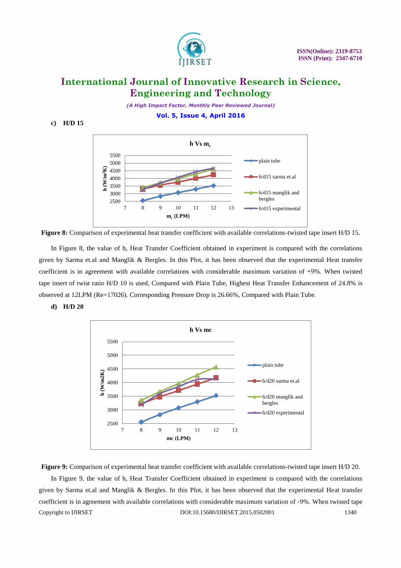
Figure 8: Comparison of experimental heat transfer coefficient with available correlations-twisted tape insert H/D 15.
In Figure 8, the value of h, Heat Transfer Coefficient obtained in experiment is compared with the correlations
given by Sarma et.al and Manglik & Bergles. In this Plot, it has been observed that the experimental Heat transfer
coefficient is in agreement with available correlations with considerable maximum variation of +9%. When twisted
tape insert of twist ratio H/D 10 is used, Compared with Plain Tube, Highest Heat Transfer Enhancement of 24.8% is
observed at 12LPM (Re=17026). Corresponding Pressure Drop is 26.66%, Compared with Plain Tube.
d) H/D 20
Figure 9: Comparison of experimental heat transfer coefficient with available correlations-twisted tape insert H/D 20.
In Figure 9, the value of h, Heat Transfer Coefficient obtained in experiment is compared with the correlations
given by Sarma et.al and Manglik & Bergles. In this Plot, it has been observed that the experimental Heat transfer
coefficient is in agreement with available correlations with considerable maximum variation of -9%. When twisted tape
2500
3000
3500
4000
4500
5000
5500
7 8 9 10 11 12 13
h (
W/m
2K
)
mc (LPM)
h Vs mc
plain tube
h/d15 sarma et.al
h/d15 manglik and
bergles
h/d15 experimental
2500
3000
3500
4000
4500
5000
5500
7 8 9 10 11 12 13
h (
W/m
2K
)
mc (LPM)
h Vs mc
plain tube
h/d20 sarma et.al
h/d20 manglik and
bergles
h/d20 experimental
ISSN(Online): 2319-8753
ISSN (Print): 2347-6710
International Journal of Innovative Research in Science,
Engineering and Technology (A High Impact Factor, Monthly Peer Reviewed Journal)
Vol. 5, Issue 4, April 2016
Copyright to IJIRSET DOI:10.15680/IJIRSET.2015.0502001 1341
insert of twist ratio H/D 10 is used, Compared with Plain Tube, Highest Heat Transfer Enhancement of 16.4% is
observed at 12LPM (Re=17677). Corresponding Pressure Drop is 30%, Compared with Plain Tube.
e) Strip Insert (without any twist)
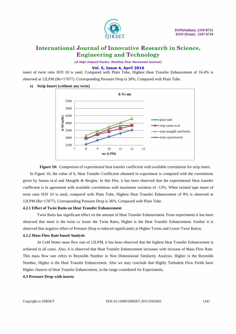
Figure 10: Comparison of experimental heat transfer coefficient with available correlations for strip insert.
In Figure 10, the value of h, Heat Transfer Coefficient obtained in experiment is compared with the correlations
given by Sarma et.al and Manglik & Bergles. In this Plot, it has been observed that the experimental Heat transfer
coefficient is in agreement with available correlations with maximum variation of -13%. When twisted tape insert of
twist ratio H/D 10 is used, compared with Plain Tube, Highest Heat Transfer Enhancement of 8% is observed at
12LPM (Re=17677). Corresponding Pressure Drop is 36%, Compared with Plain Tube.
4.2.1 Effect of Twist Ratio on Heat Transfer Enhancement
Twist Ratio has significant effect on the amount of Heat Transfer Enhancement. From experiments it has been
observed that more is the twist i.e lesser the Twist Ratio, Higher is the Heat Transfer Enhancement. Further it is
observed that negative effect of Pressure Drop is reduced significantly at Higher Twists and Lower Twist Ratios.
4.2.2 Mass Flow Rate based Analysis
At Cold Water mass flow rate of 12LPM, it has been observed that the highest Heat Transfer Enhancement is
achieved in all cases. Also, it is observed that Heat Transfer Enhancement increases with increase of Mass Flow Rate.
This mass flow rate refers to Reynolds Number in Non Dimensional Similarity Analysis. Higher is the Reynolds
Number, Higher is the Heat Transfer Enhancement. Also we may conclude that Highly Turbulent Flow Fields have
Higher chances of Heat Transfer Enhancement, in the range considered for Experiments.
4.3 Pressure Drop with inserts
2500
3000
3500
4000
4500
5000
5500
7 8 9 10 11 12 13
h (
W/m
2K
)
mc (LPM)
h Vs mc
plain tube
strip sarma et.al
strip manglik and berles
strip experimental
ISSN(Online): 2319-8753
ISSN (Print): 2347-6710
International Journal of Innovative Research in Science,
Engineering and Technology (A High Impact Factor, Monthly Peer Reviewed Journal)
Vol. 5, Issue 4, April 2016
Copyright to IJIRSET DOI:10.15680/IJIRSET.2015.0502001 1342
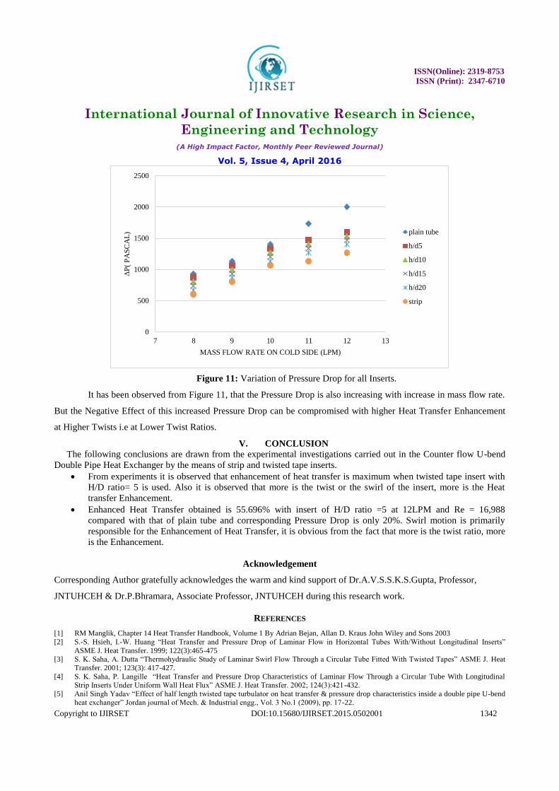
Figure 11: Variation of Pressure Drop for all Inserts.
It has been observed from Figure 11, that the Pressure Drop is also increasing with increase in mass flow rate.
But the Negative Effect of this increased Pressure Drop can be compromised with higher Heat Transfer Enhancement
at Higher Twists i.e at Lower Twist Ratios.
V. CONCLUSION
The following conclusions are drawn from the experimental investigations carried out in the Counter flow U-bend
Double Pipe Heat Exchanger by the means of strip and twisted tape inserts.
From experiments it is observed that enhancement of heat transfer is maximum when twisted tape insert with
H/D ratio= 5 is used. Also it is observed that more is the twist or the swirl of the insert, more is the Heat
transfer Enhancement.
Enhanced Heat Transfer obtained is 55.696% with insert of H/D ratio =5 at 12LPM and Re = 16,988
compared with that of plain tube and corresponding Pressure Drop is only 20%. Swirl motion is primarily
responsible for the Enhancement of Heat Transfer, it is obvious from the fact that more is the twist ratio, more
is the Enhancement.
Acknowledgement
Corresponding Author gratefully acknowledges the warm and kind support of Dr.A.V.S.S.K.S.Gupta, Professor,
JNTUHCEH & Dr.P.Bhramara, Associate Professor, JNTUHCEH during this research work.
REFERENCES
[1] RM Manglik, Chapter 14 Heat Transfer Handbook, Volume 1 By Adrian Bejan, Allan D. Kraus John Wiley and Sons 2003
[2] S.-S. Hsieh, I.-W. Huang “Heat Transfer and Pressure Drop of Laminar Flow in Horizontal Tubes With/Without Longitudinal Inserts”
ASME J. Heat Transfer. 1999; 122(3):465-475 [3] S. K. Saha, A. Dutta “Thermohydraulic Study of Laminar Swirl Flow Through a Circular Tube Fitted With Twisted Tapes” ASME J. Heat
Transfer. 2001; 123(3): 417-427.
[4] S. K. Saha, P. Langille “Heat Transfer and Pressure Drop Characteristics of Laminar Flow Through a Circular Tube With Longitudinal Strip Inserts Under Uniform Wall Heat Flux” ASME J. Heat Transfer. 2002; 124(3):421-432.
[5] Anil Singh Yadav “Effect of half length twisted tape turbulator on heat transfer & pressure drop characteristics inside a double pipe U-bend
heat exchanger” Jordan journal of Mech. & Industrial engg., Vol. 3 No.1 (2009), pp. 17-22.
0
500
1000
1500
2000
2500
7 8 9 10 11 12 13
ΔP
( P
AS
CA
L)
MASS FLOW RATE ON COLD SIDE (LPM)
plain tube
h/d5
h/d10
h/d15
h/d20
strip
ISSN(Online): 2319-8753
ISSN (Print): 2347-6710
International Journal of Innovative Research in Science,
Engineering and Technology (A High Impact Factor, Monthly Peer Reviewed Journal)
Vol. 5, Issue 4, April 2016
Copyright to IJIRSET DOI:10.15680/IJIRSET.2015.0502001 1343
[6] P. V. Durga Prasad A. V. S. S. K. S. Gupta “Augmentation of Heat Transfer and Pressure Drop Characteristics Inside a Double Pipe U-Tube
Heat Exchanger by Using Twisted Tape Insert” Journal of Emerging Trends in Science, Engineering and Technology Springer India ,33-45 2012
[7] Raj M. Manglik Arthur E. Bergles “Characterization of Twisted Tape-Induced Helical Swirl Flows for Enhancement of Forced Convective
Heat Transfer in Single-Phase and Two-Phase Flows” ASME J. Thermal Sci. Eng. Appl. 2013; 5(2): [8] B. V. N. Ramakumar, J. D. Arsha, Praveen Tayal “Tapered Twisted Tape Inserts for Enhanced Heat Transfer” ASME J. Heat Transfer. 2015;
138(1).
[9] S.N. Sarada, A.V.S.R. Raju and K.K. Radha “Experimental and Numerical Analysis of Turbulent Flow Heat Transfer Enhancement in a Horizontal Circular Tube Using Mesh Inserts” Journal of Energy and Power Engineering, ISSN 1934-8975, USA July 2010, Volume 4, No.7
(Serial No.32) David Publishing. [10] P.Murugesan, K.Mayilsamy, S.Suresh “Turbulent Heat Transfer and Pressure Drop in Tube Fitted with Square-cut Twisted Tape” Chinese
Journal of Chemical Engineering 18(4):609-617 • August 2010.
[11] S. Eiamsa-ard, C. Thianpong, P. Eiamsa-ard “Turbulent heat transfer enhancement by counter/co-swirling flow in a tube fitted with twin twisted tape” Experimental Thermal and Fluid Science Volume 34, Issue 1, January 2010, Pages 53–62
[12] S. V. Patil & P. V. Vijay Babu “Laminar Heat Transfer Augmentation through A Square Duct and Circular Tube Fitted with Twisted Tape”
Experimental Heat Transfer: A Journal of Thermal Energy Generation, Transport, Storage, and Conversion Volume 27, Issue 2, 2014 [13] Sami D. Salman, Abdul Amir H. Kadhum, Mohd S. Takriff, Abu Bakar Mohamad “CFD Simulation of Heat Transfer Augmentation in a
Circular Tube Fitted with Alternative Axis Twisted Tape in Laminar Flow under a Constant Heat Flux” WILEY Heat Transfer—Asian
Research Volume 43, Issue 4, pages 384–396, June 2014 [14] C.P. Kothandaraman, S. Subramanyan, Heat and Mass Transfer Data Book, Sixth Edition, New Age International Publishers, New Delhi,
2007
[15] Yunus.A.Cengel, Afshin.J.Ghajar, Heat and Mass Transfer, 4th edition, 2011,The McGraw-Hill Company. [16] R. M. Manglik and A. E. Bergles “Heat Transfer and Pressure Drop Correlations for Twisted-Tape Inserts in Isothermal Tubes: Part II—
Transition and Turbulent Flows” ASME J. Heat Transfer 1993; 115(4), 890-896.
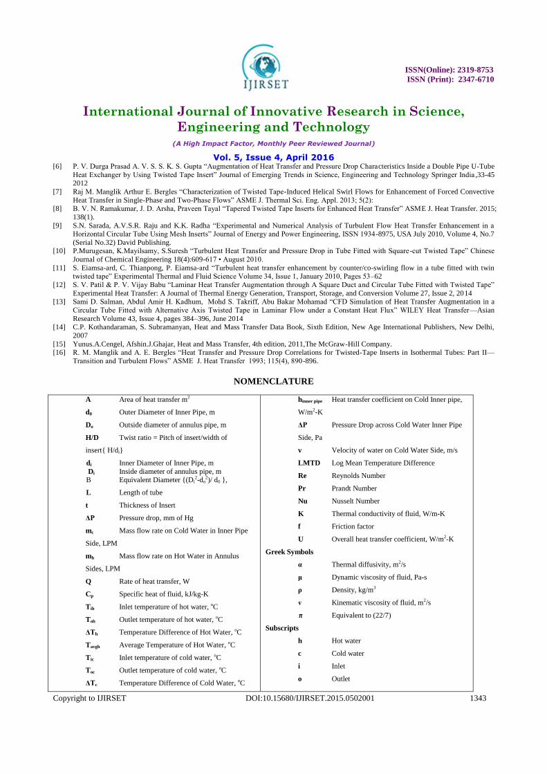
NOMENCLATURE
A Area of heat transfer m2
d0 Outer Diameter of Inner Pipe, m
Do Outside diameter of annulus pipe, m
H/D Twist ratio = Pitch of insert/width of
insert{ H/di}
di Inner Diameter of Inner Pipe, m
Di Inside diameter of annulus pipe, m B Equivalent Diameter {(Di
2-do2)/ d0 },
L Length of tube
t Thickness of Insert
ΔP Pressure drop, mm of Hg
mc Mass flow rate on Cold Water in Inner Pipe
Side, LPM
mh Mass flow rate on Hot Water in Annulus
Sides, LPM
Q Rate of heat transfer, W
Cp Specific heat of fluid, kJ/kg-K
Tih Inlet temperature of hot water, oC
Toh Outlet temperature of hot water, oC
ΔTh Temperature Difference of Hot Water, oC
Tavgh Average Temperature of Hot Water, oC
Tic Inlet temperature of cold water, oC
Toc Outlet temperature of cold water, oC
ΔTc Temperature Difference of Cold Water, oC
hinner pipe Heat transfer coefficient on Cold Inner pipe,
W/m2-K
ΔP Pressure Drop across Cold Water Inner Pipe
Side, Pa
v Velocity of water on Cold Water Side, m/s
LMTD Log Mean Temperature Difference
Re Reynolds Number
Pr Prandt Number
Nu Nusselt Number
K Thermal conductivity of fluid, W/m-K
f Friction factor
U Overall heat transfer coefficient, W/m2-K
Greek Symbols
α Thermal diffusivity, m2/s
μ Dynamic viscosity of fluid, Pa-s
ρ Density, kg/m3
ⱴ Kinematic viscosity of fluid, m2/s
π Equivalent to (22/7)
Subscripts
h Hot water
c Cold water
i Inlet
o Outlet

ISSN(Online): 2319-8753
ISSN (Print): 2347-6710
International Journal of Innovative Research in Science,
Engineering and Technology (A High Impact Factor, Monthly Peer Reviewed Journal)
Vol. 5, Issue 4, April 2016
Copyright to IJIRSET DOI:10.15680/IJIRSET.2015.0502001 1344
Tavgc Average Temperature of Cold Water, oC
hannulus Heat transfer coefficient on hot annulus side,
W/m2-K