gas-solid heat and mass transfer intensification in rotating
TRANSCRIPT

23
Gas-Solid Heat and Mass Transfer Intensification in Rotating Fluidized Beds in a
Static Geometry
Juray De Wilde Université catholique de Louvain, Dept. Materials and Process Engineering (IMAP), Place
Sainte Barbe 2, Réaumur building, 1348 Louvain-la-Neuve, Tel.: +32 10 47 2323,
Fax: +32 10 47 4028, e-mail: [email protected]
Belgium
1. Introduction
In different types of reactors, gas and solid particles are brought into contact and gas-solid
mass and heat transfer is to be optimized. This is for example the case with heterogeneous
catalytic reactions, the porous solid particle providing the catalytic sites and the reactants
having to transfer from the bulk flow to the solid surface from where they can diffuse into
the pores of the catalyst [Froment et al., 2010]. Gas-solid heat transfer can, for example, be
required to provide the heat for endothermic reactions taking place inside the solid catalyst.
Intra-particle mass transfer limitations can be encountered as well, but this chapter will
focus on interfacial mass and heat transfer. The overall rate of reaction is on the one hand
determined by the intrinsic reaction rate, which depends on the catalyst used, and on the
other hand by the rates of mass and heat transfer, which depends on the reactor
configuration and operating conditions used. Hence, the optimal use of a catalyst requires a
reactor in which conditions can be generated allowing sufficiently fast mass and heat
transfer. This is not always possible and usually an optimization is carried out accounting
for pressure drop and stability limitations. This chapter focuses on fluidized bed type
reactors and the limitations of conventional fluidized beds will be explained in more detail
in the next section.
To gain some insight in where gas-solid mass and heat transfer limitations come from,
consider the flux expression for one-dimensional diffusion of a component A over a film
around the solid particle in which the resistance for fluid-to-particle interfacial mass and
heat transfer is localized:
( )...AA t Am A A B R S
dyN C D y N N N N
dz= − + + + + + (1)
In (1), a mean binary diffusivity for species A through the mixture of other species is
introduced. For the calculation of the mean binary diffusivity, see Froment et al. [2010].
When a chemical reaction
www.intechopen.com

Heat Transfer - Theoretical Analysis, Experimental Investigations and Industrial Systems
594
... ...aA bB rR sS+ + ⇔ + + (2)
takes place, the fluxes of the different components are related through the reaction stoichiometry, so that (1) becomes:
1 ...AA t Am A A
dy b r sN C D y N
dz a a a
⎛ ⎞= − + + − − −⎜ ⎟⎝ ⎠ (3)
Solving (3) for NA:
1
At AmA
A A
dyC DN
y dzδ−= + (4)
with
... ...
A
r s a b
aδ + + − − −= (5)
Integrating (4) over the (unknown) film thickness L for steady state diffusion and using an average constant value for the mean binary diffusivity results in:
0 ( )A At AmA
fA
y y LC DN
L y
−⎛ ⎞= ⎜ ⎟⎝ ⎠ (6)
where the film factor, yfA, accounting for non-equimolar counter-diffusion, has been introduced:
( ) ( )1 1
1ln
1
sA A A As
fAA A
sA As
y yy
y
y
δ δδδ
+ − += ++
(7)
Expression (6) shows the importance of the film thickness, L, which depends on the reactor design and the operating conditions. This implies a difficulty for the practical use of (6). In practice, gas-solid mass and heat transfer are modeled in terms of a mass, respectively heat transfer coefficient, noted kg and hf. For interfacial mass transfer:
( ) ( )0gs s
A g A As A AsfA
kN k y y y y
y= − = − (8)
where the film factor was factored out, introducing the interfacial mass transfer coefficient for equimolar counter-diffusion, 0
gk . For interfacial heat transfer, the heat flux is written as:
( )sA f sQ h T T= − (9)
For the calculation of 0gk , correlations in terms of the jD factor are typically used:
0 2/3Dg
m
j Gk Sc
M
−= (10)
www.intechopen.com

Gas-Solid Heat and Mass Transfer Intensification in Rotating Fluidized Beds in a Static Geometry
595
where Sc is the Schmidt number defined as
f Am
ScD
μρ= (11)
and G is the superficial fluid mass flux through the particle bed:
( )g gG u vε ρ= − (12)
Comparing (8) and (10) to (6), it is seen that the mean binary diffusivity is enclosed in Sc.
The film thickness, L, is accounted for via the jD factor which is correlated in terms of the
Reynolds number:
(Re )D pj f= (13)
with Rep the particle based Reynolds number:
Rep
p
d G
μ= (14)
In a similar way, the heat transfer coefficient hf is usually modeled in terms of the jH factor
and the Prandtl number which contains the fluid conductivity:
2/3Prf H Ph j c G −= (15)
with
(Re )H pj f= (16)
and
Pr /Pcμ λ= (17)
Correlations (13) and (16) depend on the reactor type and design - see Froment et al. [2010]
and Schlünder [1978] for a comprehensive discussion. For conventional, gravitational
fluidized beds, Perry and Chilton [1984] proposed, for example,
0.468Re 2.05Rep p−= (18)
Balakrishnan and Pei [1975] proposed:
0.252
2
( )0.043
( )
p s g s
Hgg
d gj
u
ρ ρ ερε
⎡ ⎤−⎢ ⎥= ⎢ ⎥⎣ ⎦ (19)
Expressions (10)-(19) show in particular the importance of earth gravity, the particle bed
density, and the gas-solid slip velocity for the value of the gas-solid heat and mass transfer
coefficients.
www.intechopen.com

Heat Transfer - Theoretical Analysis, Experimental Investigations and Industrial Systems
596
2. The limitations of conventional fluidized beds
In conventional gravitational fluidized beds, particles are fluidized against gravity, a
constant on earth. This limits the window of operating conditions at which gravitational
fluidized beds can be operated. The fluidization behavior depends on the type of particles
that are fluidized. The typical fluidization behavior of fine particles is illustrated in Figure 1.
Fig. 1. Fluidization regimes with fine particles. (a) Minimum fluidization velocity; (b) Minimum bubbling; (c) Terminal velocity; (d) Blowout velocity. From Froment et al. [2010] after Squires et al. [1985].
The particle bed is fluidized when the gas-solid slip velocity exceeds the minimum
fluidization velocity of the particles. When increasing the gas velocity, the uniformly
fluidized state becomes unstable and bubbles appear (Figure 2). These meso-scale non-
uniformities are detrimental for the gas-solid contact, but their dynamic behavior improves
mixing in the particle bed. Further improvement of the gas-solid contact and the particle bed
mixing can be achieved by further increasing the gas velocity and entering into the so-called
turbulent regime. The gas-solid slip velocity can not be increased beyond the terminal
velocity of the particles, which naturally depends on the gravity field in which the particles
are suspended. Particles are then entrained by the gas and a transport regime is reached,
meaning the particles are transported with the gas through the reactor. Meso-scale non-
uniformities here appear under the form of clusters (Figure 2). The limitation of the gas-
solid slip velocity implies limitations on the gas-solid mass and heat transfer.
www.intechopen.com

Gas-Solid Heat and Mass Transfer Intensification in Rotating Fluidized Beds in a Static Geometry
597
Fig. 2. Non-uniformity in the particle distribution. Appearance of bubbles and clusters. From Agrawal et al. [2001].
Macro- to reactor-scale non-uniformities have to be avoided, as they imply complete bypassing of the solids by the gas. In gravitational fluidized beds operated in a non-transport regime, this requires a certain weight of particles above the gas distributor and limits the particle bed width-to-height ratio. This on its turn introduces a constraint on the fluidization gas flow rate that can be handled per unit volume particle bed. In the transport regime, particles have to be returned from the top of the reactor to the bottom. The driving force is the weight of particles in a stand pipe and, hence, the latter should be sufficiently tall. The reactor length has to be adapted accordingly, resulting in very tall reactors. The riser reactors used in FCC, for example, are 30 to 40 m tall. The resulting gas phase and catalyst residence times in some applications limit the catalyst activity. An important characteristic of the fluidized bed state is the particle bed density. It is directly related to the process intensity that can be reached in the reactor. The process intensity for a given reactor can be defined as how much reactant is converted per unit time and per unit reactor volume. Typically, as the gas velocity is increased, the particle bed expands and the particle bed density decreases. In a transport regime, the average particle bed density decreases significantly. In the riser regime, for example, the reactor is typically operated at 5 vol% solids or less. The process intensity is correspondingly low. A final important limitation of gravitational fluidized beds comes from the type of particles that can be fluidized. Nano- and micro-scale particles can not be properly fluidized, the Van der Waals forces becoming too important compared to the other forces determining the fluidized bed state, i.e. the weight of the particles and the gas-solid drag force. Most of the above mentioned limitations of gravitational fluidized beds can be removed by replacing earth gravity with a stronger force - so-called high-G operation. This has led to the development of the cylindrically shaped so-called rotating fluidized beds. A first technology of this type is based on a fluidization chamber which rotates fast around its axis of symmetry by means of a motor [Fan et al., 1985; Chen, 1987]. The moving geometry
www.intechopen.com

Heat Transfer - Theoretical Analysis, Experimental Investigations and Industrial Systems
598
complicates sealing and continuous feeding and removal of solids and introduces additional challenges related to vibrations. Nevertheless, rotating fluidized beds have been shown successful in removing the limitations of gravitational fluidized beds and, for example, allow the fluidization of micro- and nano-particles [Qian et al., 2001; Watano et al., 2003; Quevedo et al., 2005]. In this chapter, a novel technology is focused on that allows taking advantage of high-G operation in a static geometry. The gas-solid heat and mass transfer properties and the particle bed temperature uniformity are numerically and experimentally studied. The process intensification is illustrated for the drying of biomass and for FCC.
3. The rotating fluidized beds in a static geometry
3.1 Technology description Figure 3 shows a schematic representation of a rotating fluidized bed in a static geometry (RFB-SG) [de Broqueville, 2004; De Wilde and de Broqueville, 2007, 2008], a vortex chamber [Kochetov et al., 1969; Anderson et al., 1971; Folsom, 1974] based technology. The unique characteristic of the technology is the way the rotational motion of the particle bed is driven, i.e. by the tangential introduction of the fluidization gas in the fluidization chamber through multiple inlet slots in its outer cylindrical wall. As a result, the particle bed is, or better can be, fluidized in two directions. The fluidization gas is forced to leave the fluidization chamber via a centrally positioned chimney. The radial fluidization of the particle bed is then controlled by the radial gas-solid drag force and the solid particles inertia. In a coordinate system rotating with the particle bed, the latter appears as the centrifugal and Coriolis forces. Radial fluidization of the particle bed is, however, not essential to take fully advantage of high-G operation. What is essential for intensifying gas-solid mass and heat transfer is the increased gas-solid slip velocity at which the bed can be operated while maintaining a high particle bed density and being fluidized.
Fig. 3. The rotating fluidized bed in a static geometry. Picture from De Wilde and de Broqueville [2007].
www.intechopen.com

Gas-Solid Heat and Mass Transfer Intensification in Rotating Fluidized Beds in a Static Geometry
599
Whether the particle bed will be radially fluidized depends mainly on the type of particles and on the fluidization chamber design, including the fluidization chamber and chimney diameters and the number and size of the gas inlets slots. At fluidization gas flow rates sufficiently high to operate high-G, the influence of the fluidization gas flow rate on the radial fluidization of the particle bed is marginal. This flexibility in the fluidization gas flow rate is an important and unique feature of rotating fluidized beds in a static geometry [De Wilde and de Broqueville, 2007, 2008, 2008b]. The explanation for this comes from the similar influence of the fluidization gas flow rate on the radial gas-solid drag force and the counteracting solid phase inertial forces resulting from the particle bed rotational motion. Experimental observations confirm the absence of radial bed expansion when increasing the fluidization gas flow rate. In some cases, even a radial bed contraction was observed. Another important characteristic of rotating fluidized beds in a static geometry is the excellent particle bed mixing, resulting from the particle bed rotational motion and the fluctuations in the velocity field of the particles. The particle bed mixing properties were studied by De Wilde [2009] by means of a step response technique with colored particles and a close to well-mixed behavior was demonstrated at sufficiently high fluidization gas flow rates. It should be remarked that the gas phase is hardly mixed and follows a plug flow type pattern.
3.2 Theoretical evaluation of the intensification of gas-solid heat and mass transfer As mentioned in Section 2 of this chapter, in fluidized beds, the gas-solid slip velocity, essential for the value of the gas-solid heat and mass transfer coefficient - see (10), (12), and (15), can not increase beyond the terminal velocity of the particles. An expression for the latter has been derived for gravitational fluidized beds [Froment et al., 2010] and can be extended to fluidization in a high-G field as:
4 ( )
3
p s gterm
g D
c du
C
ρ ρρ
⋅ −= (20)
with c the high-G acceleration. The value of the drag coefficient, CD, depends on the particle Reynolds number, Rep. For Rep below 1000:
( )0.687241 0.15Re
ReD p
p
C = + (21)
with, for spherical particles:
Reg g p
p
u v dε ρμ
−= (22)
, similar to (14). For higher Rep:
0.44DC = (23)
A unique characteristic of rotating fluidized beds in a static geometry is that the high-G acceleration appearing in (20) depends on the fluidization gas flow rate and, hence, on the gas velocity u. An estimation of the high-G acceleration can be calculated from an expression derived by de Broqueville and De Wilde [2009]. Assuming a solid body type motion of the particle bed and neglecting the contribution of the Coriolis effect:
www.intechopen.com

Heat Transfer - Theoretical Analysis, Experimental Investigations and Industrial Systems
600
( )( )
2tan tan
2
2 2
2 g gg
g f
F n v uc r r
R R Lω ε
⎛ ⎞⋅ ⋅ ⋅⎜ ⎟= = ⎜ ⎟⋅ − ⋅⎜ ⎟⎝ ⎠ (24)
where r is the radial position in the particle bed, Fg is the fluidization gas flow rate, <n> is the average number of rotations made by the fluidization gas in the particle bed, <εg> is the average particle bed void fraction, R is the outer fluidization chamber radius, Rf is the particle bed freeboard radius, and L is the fluidization chamber length. In case the fluidization gas injected via a given gas inlet slot leaves the particle bed when approaching the next gas inlet slot, as experimentally observed by De Wilde [2009]:
-1~[number of gas inlet slots]n (25)
The average tangential gas-solid slip factor, <vtang>/<utang>, is determined by the shear resulting from particle-particle and particle-wall collisions and by the tangential gas-solid drag force. In the immediate vicinity of the gas inlet slots, strong variations in its value occur. Substituting (24) in (20),
( )( )
tan tan
2 2
2 4 ( )
3
g gg p s gterm
g Dg f
F n v u r du
CR R L
ρ ρρε
⎛ ⎞⋅ ⋅ ⋅ ⋅ −⎜ ⎟= ⋅⎜ ⎟ ⋅⋅ − ⋅⎜ ⎟⎝ ⎠ (26)
At sufficiently high Rep, (23) can be applied, and the terminal velocity of the particles is seen to be proportional to the fluidization gas flow rate and to the square root of the radial distance from the fluidization chamber central axis. The proportionality factor depends on the gas and solid phase properties and on the fluidization chamber design. A similar analysis can be derived for the minimum fluidization velocity. Extending the expression of Wen and Yu [1966] to high-G operation:
Remf
mfp g
ud
μρ= (27)
with:
21 2 1Remf C C Ar C= + − (28)
and:
( )3
2
p g s gd cAr
ρ ρ ρμ−= (29)
Wen and Yu [1966] found C1 = 33.7 and C2 = 0.0408. Again using relation (24) between the high-G acceleration and the fluidization gas flow rate results in:
( ) ( )( )
2tan tan3
2 2 2
2 g ggp g s g
g f
F n v udAr r
R R L
ρ ρ ρμ ε
⎛ ⎞⋅ ⋅ ⋅− ⎜ ⎟= ⎜ ⎟⋅ − ⋅⎜ ⎟⎝ ⎠ (30)
www.intechopen.com

Gas-Solid Heat and Mass Transfer Intensification in Rotating Fluidized Beds in a Static Geometry
601
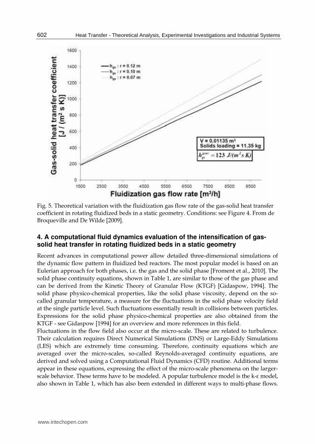
Equation (30) shows that, like the terminal velocity, the minimum fluidization velocity of the particles increases with the fluidization gas flow rate and with the radial distance from the central axis of the fluidization chamber. Figure 4 illustrates the theoretical variation with the fluidization gas flow rate of the minimum fluidization and terminal velocities of the particles in rotating fluidized beds in a static geometry [de Broqueville and De Wilde, 2009]. In the case studied, the radial gas(-solid slip) velocity in the particle bed remained well between the minimum fluidization velocity and the terminal velocity of the particles over the entire fluidization gas flow rate range. Figure 5 shows the corresponding gas-solid heat transfer coefficients that can be obtained. Compared to conventional fluidized beds, rotating fluidized beds in a static geometry easily allow a one order of magnitude intensification of gas-solid heat and mass transfer.
Fig. 4. Theoretical variation with the fluidization gas flow rate of the minimum fluidization and terminal velocities of the particles in rotating fluidized beds in a static geometry. Radial gas(-solid slip) velocity also shown. Conditions: ρg = 1.0 kg/m3, ρs = 2500 kg/m3, dp = 700 µm, R = 0.18 m, Rc = 0.065 m, L = 0.135 m, <εs> = 0.4, <n> = 0.042 = 1/24, <vtang>/<utang> = 0.7. From de Broqueville and De Wilde [2009].
The minimum fluidization and terminal velocities being nearly proportional to the fluidization gas flow rate in rotating fluidized beds in a static geometry results from the counteracting forces - radial gas-solid drag force and solid phase inertial forces - being affected by the fluidization gas flow rate in a similar way. It should be stressed that, as illustrated in Figure 4, this implies a unique flexibility in the fluidization gas flow rate and in the gas-solid slip velocities and related gas-solid heat and mass transfer coefficients at which rotating fluidized beds in a static geometry can be operated.
www.intechopen.com
Heat Transfer - Theoretical Analysis, Experimental Investigations and Industrial Systems
602
Fig. 5. Theoretical variation with the fluidization gas flow rate of the gas-solid heat transfer coefficient in rotating fluidized beds in a static geometry. Conditions: see Figure 4. From de Broqueville and De Wilde [2009].
4. A computational fluid dynamics evaluation of the intensification of gas-solid heat transfer in rotating fluidized beds in a static geometry
Recent advances in computational power allow detailed three-dimensional simulations of
the dynamic flow pattern in fluidized bed reactors. The most popular model is based on an
Eulerian approach for both phases, i.e. the gas and the solid phase [Froment et al., 2010]. The
solid phase continuity equations, shown in Table 1, are similar to those of the gas phase and
can be derived from the Kinetic Theory of Granular Flow (KTGF) [Gidaspow, 1994]. The
solid phase physico-chemical properties, like the solid phase viscosity, depend on the so-
called granular temperature, a measure for the fluctuations in the solid phase velocity field
at the single particle level. Such fluctuations essentially result in collisions between particles.
Expressions for the solid phase physico-chemical properties are also obtained from the
KTGF - see Gidaspow [1994] for an overview and more references in this field.
Fluctuations in the flow field also occur at the micro-scale. These are related to turbulence.
Their calculation requires Direct Numerical Simulations (DNS) or Large-Eddy Simulations
(LES) which are extremely time consuming. Therefore, continuity equations which are
averaged over the micro-scales, so-called Reynolds-averaged continuity equations, are
derived and solved using a Computational Fluid Dynamics (CFD) routine. Additional terms
appear in these equations, expressing the effect of the micro-scale phenomena on the larger-
scale behavior. These terms have to be modeled. A popular turbulence model is the k-ε model,
also shown in Table 1, which has also been extended in different ways to multi-phase flows.
www.intechopen.com

Gas-Solid Heat and Mass Transfer Intensification in Rotating Fluidized Beds in a Static Geometry
603
Table 1. Eulerian-Eulerian approach. Continuity equations for each phase.
www.intechopen.com

Heat Transfer - Theoretical Analysis, Experimental Investigations and Industrial Systems
604
Such extensions are, however, purely empirical. In gas-solid flows, additional meso-scale structures related to a non-uniform distribution of the particles develop [Agrawal et al., 2001]. Depending on the operating conditions, clusters of particles and gas bubbles are typically observed. Meso-scale structures cover the range from the micro- to the macro-scale, so that there is no separation of scales. The calculation of the dynamics of meso-scale structures is time consuming. Averaging the continuity equations over the meso-scales is theoretically possible, see Agrawal et al. [2001], Zhang and VanderHeyden [2002] and De Wilde [2005, 2007], but modeling the additional terms that appear is challenging. No reliable closure relations exist at this time. Therefore, dynamic simulations using a sufficiently fine spatial and temporal mesh are to be carried out. Boundary conditions have to be imposed at solid walls. For gas-solid flows, they are usually based on a no-slip behavior for the gas phase and a partial slip behavior for the solid phase. Johnson and Jackson [1987] proposed a model introducing a specularity coefficient and a particle-wall restitution coefficient for which values of 0.2 and 0.9 were used by Trujillo and De Wilde [2010].
Table 2. Simulation conditions for the CFD step response study of gas-solid heat transfer in gravitational fluidized beds and rotating fluidized beds in a static geometry by de Broqueville and De Wilde [2009].
www.intechopen.com

Gas-Solid Heat and Mass Transfer Intensification in Rotating Fluidized Beds in a Static Geometry
605
By means of CFD, de Broqueville and De Wilde [2009] studied the response of the particle bed temperature to a step change in the fluidization gas temperature. Over a range of fluidization gas flow rates, a comparison between gravitational fluidized beds and rotating fluidized beds in a static geometry was made. The simulation conditions are summarized in Table 2. It should be remarked that the fluidization gas flow rate was close to the maximum possible value, i.e. for avoiding particle entrainment by the gas, for the gravitational fluidized bed, but not for the rotating fluidized bed in a static geometry, due to its unique flexibility explained above.
Fig. 6. Response of the average particle bed temperature to a step change in the fluidization gas temperature. Comparison of gravitational fluidized beds and rotating fluidized beds in a static geometry with equal solids loading at different fluidization gas flow rates. Conditions: see Table 2. From de Broqueville and De Wilde [2009].
Figure 6 shows that the particle bed temperature can respond much faster to changes in the fluidization gas temperature in rotating fluidized beds in a static geometry than in gravitational fluidized beds. This is due to a combination of effects. High-G operation allows higher gas-solid slip velocities and, as such, higher gas-solid heat transfer coefficients. The unique flexibility in the fluidization gas flow rate and radial gas-solid slip velocity was demonstrated in Figures 4 and 5. Also, the particle bed is cylindrically shaped in rotating fluidized beds in a static geometry, resulting in a higher particle bed width-to-height ratio than in gravitational fluidized beds. This, combined with the higher allowable radial gas-solid slip velocities, allows much higher fluidization gas flow rates per unit volume particle
www.intechopen.com
Heat Transfer - Theoretical Analysis, Experimental Investigations and Industrial Systems
606
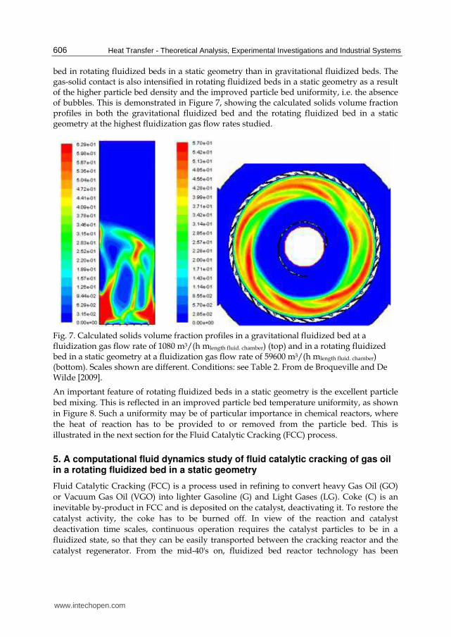
bed in rotating fluidized beds in a static geometry than in gravitational fluidized beds. The gas-solid contact is also intensified in rotating fluidized beds in a static geometry as a result of the higher particle bed density and the improved particle bed uniformity, i.e. the absence of bubbles. This is demonstrated in Figure 7, showing the calculated solids volume fraction profiles in both the gravitational fluidized bed and the rotating fluidized bed in a static geometry at the highest fluidization gas flow rates studied.
Fig. 7. Calculated solids volume fraction profiles in a gravitational fluidized bed at a fluidization gas flow rate of 1080 m3/(h mlength fluid. chamber) (top) and in a rotating fluidized bed in a static geometry at a fluidization gas flow rate of 59600 m3/(h mlength fluid. chamber) (bottom). Scales shown are different. Conditions: see Table 2. From de Broqueville and De Wilde [2009].
An important feature of rotating fluidized beds in a static geometry is the excellent particle
bed mixing. This is reflected in an improved particle bed temperature uniformity, as shown
in Figure 8. Such a uniformity may be of particular importance in chemical reactors, where
the heat of reaction has to be provided to or removed from the particle bed. This is
illustrated in the next section for the Fluid Catalytic Cracking (FCC) process.
5. A computational fluid dynamics study of fluid catalytic cracking of gas oil in a rotating fluidized bed in a static geometry
Fluid Catalytic Cracking (FCC) is a process used in refining to convert heavy Gas Oil (GO)
or Vacuum Gas Oil (VGO) into lighter Gasoline (G) and Light Gases (LG). Coke (C) is an
inevitable by-product in FCC and is deposited on the catalyst, deactivating it. To restore the
catalyst activity, the coke has to be burned off. In view of the reaction and catalyst
deactivation time scales, continuous operation requires the catalyst particles to be in a
fluidized state, so that they can be easily transported between the cracking reactor and the
catalyst regenerator. From the mid-40's on, fluidized bed reactor technology has been
www.intechopen.com

Gas-Solid Heat and Mass Transfer Intensification in Rotating Fluidized Beds in a Static Geometry
607
(a) Gravitational fluidized bed
(b) Rotating fluidized bed in a static geometry
Fig. 8. Calculated temperature profiles (a) in a gravitational fluidized bed at a fluidization gas flow rate of 1080 m3/(h mlength fluid. chamber) and (b) in a rotating fluidized bed in a static geometry at a fluidization gas flow rate of 29800 m3/(h mlength fluid. chamber). Conditions: see Table 2. From de Broqueville and De Wilde [2009].
www.intechopen.com

Heat Transfer - Theoretical Analysis, Experimental Investigations and Industrial Systems
608
developed in this context. The process is designed in such a way that the heat of combustion generated by burning off the coke is used for the endothermic cracking reactions, the circulating catalyst being the heat carrier. The original technology made use of a cracking reactor operated in the bubbling or turbulent regime (Figure 1). As catalysts became more active, riser reactors were introduced. FCC riser reactors are 30 to 40 m tall with a diameter of typically 0.85 m. Operating in the riser regime, the particle bed density is low, with typically a solids volume fraction below 5%. The catalyst leaving the riser reactor is separated from the gaseous product in cyclones and goes via a stripper section to the regenerator. Partial or complete combustion of the coke is possible, depending on the feed cracked and the resulting coke formation and the energy requirements for the cracking reactions. The regenerated catalyst is returned to the riser via standpipes by the action of gravity. A sufficient standpipe height is required and this on its turn imposes a certain riser height. The cracking temperature in the riser reactor is limited to avoid over-cracking and temperature non-uniformities. Significant intensification of the FCC process is possible. The particle bed density can be drastically increased, that is, by a factor 10. To avoid over-cracking under such conditions, the gas phase residence time has to be sharply decreased. This can be done by increasing the gas phase velocity, reducing the particle bed height, or a combination of these. Also the gas-solid heat transfer has to be intensified. This is possible by increasing the gas-solid slip velocity. Finally, to avoid temperature non-uniformities, the particle bed mixing can be improved. From the previous Sections 3 and 4, the potential of rotating fluidized beds for intensifying the FCC process is clear. Important challenges do, however, remain. Some of these were addressed by Trujillo and De Wilde [2010], who in particular demonstrated that sufficiently high conversions can be achieved in rotating fluidized beds in a static geometry. Furthermore, a one order of magnitude process intensification was predicted.
Fig. 9. Ten-lump model for the catalytic cracking of gas oil [Jacob et al., 1976].
The CFD simulations by Trujillo and De Wilde [2010] made use of the Eulerian-Eulerian approach already described in Section 4. The basic set of continuity equations, shown in Table 1, has to be extended to account for the reactions between different species. The catalytic cracking of gas oil was described by a 10-lump model, shown in Figure 9 [Jacob et
www.intechopen.com

Gas-Solid Heat and Mass Transfer Intensification in Rotating Fluidized Beds in a Static Geometry
609
al., 1976]. The C-lump is a mixture of coke and light gases (C1 - C4). The effects of the adsorption of heavy aromatics and of catalyst deactivation by coke on the reaction rates were accounted for. Two-dimensional periodic domain simulations of a 12-slot, 1.2 m diameter, polygonal body RFB-SG type reactor were carried out and a comparison with a 30 m tall riser was made. Details on the simulation model and on the reactor geometries simulated can be found in Trujillo and De Wilde [2010].
(a) (b)
Fig. 10. FCC process intensification using rotating fluidized beds in a static geometry. Comparison with riser technology. (a) Gas Oil conversion as a function of the normalized coordinate; (b) Intrinsic process intensification factor as a function of the Gas Oil conversion. Conventional cracking catalyst and cracking temperature of 775 K. From Trujillo and De Wilde [2010].
(a) (b)
Fig. 11. FCC process intensification using rotating fluidized beds in a static geometry at increased cracking temperatures. Comparison with conventional riser technology. (a) Gas Oil conversion in the RFB-SG as a function of the radial coordinate; (b) Process intensification factor as a function of the Gas Oil conversion for different cracking temperatures. Conventional cracking catalyst and cracking temperature of 775 K. From Trujillo and De Wilde [2010].
www.intechopen.com

Heat Transfer - Theoretical Analysis, Experimental Investigations and Industrial Systems
610
The simulations first focused on the intrinsic process intensification potential of rotating fluidized beds in a static geometry, that is, operating at cracking temperatures and with the same catalyst used in riser reactors. Figure 10 shows the gas oil conversion as a function of the normalized coordinate and the intrinsic process intensification factor as a function of the gas oil conversion for a non-optimized RFB-SG reactor design. With an optimized geometry, intrinsic process intensification by one order of magnitude can be easily achieved. Furthermore, due to the improved temperature uniformity in the particle bed, operation at higher cracking temperatures or working with a ore active catalyst is possible. Simulations at higher cracking temperatures, for example, shown in Figure 11, showed that process intensification by a factor 20 is within reach. This nicely illustrates the advantage that can be taken from the increased gas-solid mass and heat transfer coefficients and the improved particle bed density and uniformity in rotating fluidized beds in a static geometry.
6. Experimental evaluation of the intensification of drying of granular material in rotating fluidized beds in a static geometry
The intensification of gas-solid mass and heat transfer in rotating fluidized beds in a static geometry should allow intensifying the drying of granular material. Eliaers and De Wilde [2010] compared drying of biomass particles in a conventional fluidized bed and in a rotating fluidized bed in a static geometry. Batch and continuous flow experiments were carried out. The fluidization chamber dimensions and the operating conditions for the continuous flow experiments are summarized in Table 3.
Conventional
fluidized bed Rotating fluidized bed
in a static geometry Dimensions D = 0.10 m
H = 2.00 m D = 0.43 m D(chimney) = 0.10 m L = 0.24 m
Gas distribution Cone and perforated plate
72, 30° inclined gas inlet slots
Solids feeding Via side wall at h = m
Via end plate
Particle characteristics Pelletized wood, cylindrically shaped, dp = 4 mm, hp = 4 mm
Operating conditions
T [K] 318
Pout [Pa] 101300
Gas mass flow rate [Nm3/h] 110 700
Solids mass flow rate [g wet solids / s]
1, 2, 3, 6, 9 3, 6, 9, 12, 15, 18
Solids inlet humidity [g water / kg dry solids]
850
Table 3. Comparison of the drying of biomass particles in a conventional fluidized bed and in a rotating fluidized bed in a static geometry. Fluidization chamber dimensions and operating conditions.
www.intechopen.com

Gas-Solid Heat and Mass Transfer Intensification in Rotating Fluidized Beds in a Static Geometry
611
The pelletized wood particles have mainly macro-pores, so that intra-particle diffusion limitations are not expected to be dominant in the range of drying conditions studied.
(a)
(b)
Fig. 12. Comparison of drying of biomass particles in a gravitational fluidized bed and in a rotating fluidized bed in a static geometry. (a) Specific drying rate in g water transferred per m3 reactor and per second as a function of the solids feeding rate; (b) Specific drying rate in g water transferred per g dry solids and per second as a function of the solids feeding rate. Fluidization chamber dimensions and operating conditions: see Table 3. From Eliaers and De Wilde [2010].
Intensification of the drying process can be due to an increased particle bed density and improved particle bed uniformity, on the one hand, and increased gas-solid mass and heat transfer coefficients, on the other hand. For the conditions studied, the value of the gas-solid mass and heat transfer coefficients are comparable in the gravitational fluidized bed and in the RFB-SG. The gas-solid slip velocity in both the gravitational and the rotating fluidized
www.intechopen.com
Heat Transfer - Theoretical Analysis, Experimental Investigations and Industrial Systems
612
bed in a static geometry is around 4.7 m/s. Hence the intensification comes exclusively from the increased particle bed density and improved particle bed uniformity. Accounting for mean particle bed solids volume fractions of about 4 % in the gravitational fluidized bed and about 25 % in the RFB-SG, there is a theoretical process intensification potential of easily a factor 6. When operating the RFB-SG at higher fluidization gas flow rates, further intensification of the drying process resulting from increased gas-solid mass and heat transfer coefficients may be achieved.
(a)
(b)
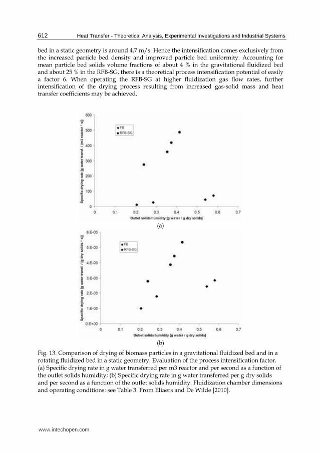
Fig. 13. Comparison of drying of biomass particles in a gravitational fluidized bed and in a rotating fluidized bed in a static geometry. Evaluation of the process intensification factor. (a) Specific drying rate in g water transferred per m3 reactor and per second as a function of the outlet solids humidity; (b) Specific drying rate in g water transferred per g dry solids and per second as a function of the outlet solids humidity. Fluidization chamber dimensions and operating conditions: see Table 3. From Eliaers and De Wilde [2010].
www.intechopen.com

Gas-Solid Heat and Mass Transfer Intensification in Rotating Fluidized Beds in a Static Geometry
613
Figures 12 and 13 compare the specific drying rates in the gravitational fluidized bed and the RFB-SG, expressed in g water transferred per second and either per m3 reactor (a) or per g dry solids (b), respectively as a function of the solids feeding rate or as function of the outlet solids humidity. The specific drying rate expressed per g dry solids allows evaluating the process intensification due to increased gas-solid slip velocities and the improved particle bed uniformity. The specific drying rate expressed per m3 reactor then allows evaluating the additional process intensification due to the increased particle bed density. Evaluation of the process intensification is best done at equal outlet solids humidity as shown in Figure 13. The biomass drying process intensification in RFB-SGs is logically the most pronounced at higher outlet solids humidity. With decreasing outlet solids humidity, intra-particle diffusion grows in importance. Figure 13(b) shows that in the range of conditions studied, the improved particle bed uniformity in the RFB-SG results in process intensification with between a factor 2 and 4. As seen from Figure 13(a), the increased particle bed density in the RFB-SG results in additional process intensification and a global process intensification factor of between 10 and 16. As mentioned previously, the process intensification resulting from the use of a RFB-SG can be further increased by operating at higher fluidization gas flow rates.
7. Chapter summary
A theoretical analysis of gas-solid mass and heat transfer shows a significant potential for fluidized bed process intensification by replacing earth gravity with a stronger acceleration. In rotating fluidized beds, the inertia of the solid particles is used to achieve high-G operation. A new type of rotating fluidized bed, i.e., in a static geometry, is studied in this chapter. The rotating motion of the particle bed is generated by the tangential injection of the fluidization gas in the fluidization chamber, via multiple gas inlet slots. A unique flexibility in the fluidization gas flow rate results from the counteracting radial gas-solid drag force and solid phase inertial forces being affected by the fluidization gas flow rate in a similar way. A significant process intensification potential is theoretically expected, resulting from, on the one hand, an increased particle bed density and improved particle bed uniformity and, on the other hand, increased gas-solid mass and heat transfer coefficients. Furthermore, the intense particle bed mixing results in significantly improved particle bed temperature uniformity. Computational Fluid Dynamics (CFD) simulations confirm these promising characteristics of rotating fluidized beds in a static geometry. Application to fluid catalytic cracking (FCC) and to biomass drying is discussed. In FCC, the use of a rotating fluidized bed in a static geometry allows intrinsic process intensification by one order of magnitude. Additional process intensification can be achieved by operating at higher cracking temperatures, which becomes possible due to the improved particle bed temperature uniformity. The use of a more active catalyst can also be considered. Experimental data on drying of biomass particles confirm the theoretically expected process intensification potential. Again, process intensification by one order of magnitude can be easily achieved.
8. Acknowledgments
Waldo Rosales Trujillo is acknowledged for his help with the CFD calculations on the fluid catalytic cracking process. Philippe Eliaers is acknowledged for his help with the drying experiments. Axel de Broqueville is acknowledged for his collaboration.
www.intechopen.com

Heat Transfer - Theoretical Analysis, Experimental Investigations and Industrial Systems
614
Notations
as external particle surface area per unit mass particle [m2/kg solid]
tC total molar concentration of active sites [ kmol / kgcat. ] c acceleration of high-gravity field [ 2m / s ]
pc specific heat of fluid at constant pressure [kJ/kg K] DAm molecular diffusivity for A in a multicomponent mixture [ 3
f fm / m s ] dp particle diameter [m] eg gas phase internal energy [kJ kg-1] es solid phase internal energy [kJ kg-1] Fg fluidization gas flow rate; [m3 s-1] in 2D, per unit length fluidization chamber [mg3/(h mlength fluid. chamber)]
G superficial mass flow velocity; [ 2rkg / m s ]
g acceleration of gravity [ 2m / s ]
fh , hgs heat transfer coefficient for film surrounding a particle [ 2PkJ / m sK ]
Dj j-factor for mass transfer
Hj j-factor for heat transfer k gas phase turbulent kinetic energy [kJ kg-1]
0gk mass transfer coefficient in case of equimolar counterdiffusion [ 3
f im / m s ] L length of the fluidization chamber [m] L film thickness [m]
mM mean molecular mass [kg/kmol]
AN molar flux of A with respect to fixed coordinates [kmol/m² s] <n> average number of rotations of the fluidization gas in the particle bed P gas phase pressure [Pa] Ps solid phase pressure [Pa]
Pr Prandtl number, /pc μ λ qg gas phase kinetic energy [kJ kg-1] qs solid phase kinetic energy [kJ kg-1] Q, Qgs gas-solid heat transfer [kJ/(s m3reactor)] r radial distance from the center of the fluidization chamber [m]
r position vector R Outer fluidization chamber radius [m] Rf Particle bed freeboard radius [m] Rc Chimney radius [m]
Sc Schmidt number, μ/ρD s viscous stress tensor [kg m-1 s-2] T temperature [K]
ssT temperature inside solid, resp. at solid surface [K]
t time [s] u gas phase velocity [m/s] V volume of the fluidization chamber [m3] v solid phase velocity [m/s] yA, yB mole fraction of species A, B …
β drag coefficient [kg m-3 s-1]
γ dissipation of kinetic fluctuation energy by inelastic particle-particle collisions [kg mr-1 s-3]
www.intechopen.com

Gas-Solid Heat and Mass Transfer Intensification in Rotating Fluidized Beds in a Static Geometry
615
ε dissipation of turbulent kinetic energy of the gas phase [mr2 s-3]
εg gas phase volume fraction [ 3 3g rm / m ] ε s solid phase volume fraction [ 3 3s rm / m ]
Θ granular temperature [kJ/kg]
κ granular temperature conductivity [kg m-1 s-1] λ thermal conductivity [kJ/m s K] μ dynamic viscosity [kg/m s] ω angular velocity [rad s-1] ρ f fluid density [ 3
fkg / m ] ρg gas density [ 3Gkg / m ] ρs density of catalyst [ 3
pkgcat. / m ]
Subscript / superscript
g gas phase p particle s solid phase r radial rad radial t, tang tangential term terminal
9. References
Agrawal, K., Loezos, P.N., Syamlal, M., and Sundaresan, S., J. Fluid Mech., 445, 151 (2001). Anderson, L.A., Hasinger, S., and Turman, B.N., A.I.A.A. paper, 71, 637 (1971). Balakrishnan, A.R., and Pei, D.C.T., Can. J. Chem. Eng., 53, 231 (1975). Chen, Y.-M., A.I.Ch.E. J., 33 (5), 722 (1987). de Broqueville, A., 2004. Belgian Patent 2004/0186, Internat. Classif. : B01J C08F B01F;
publication number: 1015976A3. de Broqueville, A., De Wilde, J., Chem. Eng. Sci., 64 (6), 1232 (2009). De Wilde, J., Physics of Fluids, 17:(11), Art. No. 113304 (2005). De Wilde, J., Physics of Fluids, 19:(5), 058103 (2007). De Wilde, J., de Broqueville, A., A.I.Ch.E. J., 53 (4), 793 (2007). De Wilde, J., de Broqueville, A., Powder Technol., 183 (3), 426 (2008). De Wilde, J., de Broqueville, A., A.I.Ch.E. J., 54 (8), 2029 (2008b). De Wilde, J., proc., OA70, North American Catalysis Society, 21st National (North
American) Annual Meeting (21st NAM), San Francisco, CA, USA, June 7-12 (2009). Eliaers, P., De Wilde, J., UCL report 270810 (2010). Fan, L.T., Chang, C.C., Yu, Y.S., Takahashi, T., Tanaka, Z., A.I.Ch.E. J., 31 (6), 999 (1985). Folsom, B.A., PhD thesis, California Institute of Technology (1974). Froment, G.F., Bischoff, K.B., and De Wilde, J., Chemical Reactor Analysis and Design, Third
edition, Wiley (2010). Gidaspow, D., Multiphase Flow and Fluidization: Continuum and Kinetic Theory
Descriptions, Academic Press (1994). Jacob, S.M., Gross, B., Voltz, S.E., Jr. V.W. W., A.I.Ch.E. J., 22, 701 (1976). Johnson, P.C., Jackson, R., J. Fluid Mech., Digital Archive, 176, 67 (1987).
www.intechopen.com

Heat Transfer - Theoretical Analysis, Experimental Investigations and Industrial Systems
616
Kochetov, L.M., Sazhin, B.S., Karlik, E.A., Khimicheskoe i Neftyanoe Mashinostroenie, 2, 10 (1969).
Perry, R.H., Chilton, C.H., Chemical Engineers Handbook, 6th ed., McGrawHill, NY (1984). Qian, G.-H., Bagyi, I., Burdick, I.W., Pfeffer, R., Shaw, H., Stevens, J.G., A.I.Ch.E. J., 47 (5),
1022 (2001). Quevedo, J.A., Nakamura, H., Shen, Y., Dave, R.N., Pfeffer, R., Proceedings of AIChE
Annual meeting 2005, Cincinnati, OH, USA (2005). Schlünder, E.U., in Chemical Reaction Engineering Reviews-Houston, ed. by D. Luss and
V.W. Weekman, A.C.S. Symp. Series, 72, Washington, D.C. (1978). Squires, A. M., Kwauk, M., and Avidan, A. A., Science, 230 (4732), 1329 (1985). Watano, S., Imada, Y., Hamada, K., Wakamatsu, Y., Tanabe, Y., Dave, R.N., Pfeffer, R.,
Powder Technol. 131 (2-3), 250 (2003). Wen, Y.C., Yu, Y.H., Chem. Eng. Progr. Symp. Ser., 62 (62), 100 (1966). Zhang, D.Z., VanderHeyden, W.B., Int. J. Multiphase Flow, 28 (5), 805 (2002).
www.intechopen.com

Heat Transfer - Theoretical Analysis, Experimental Investigationsand Industrial SystemsEdited by Prof. Aziz Belmiloudi
ISBN 978-953-307-226-5Hard cover, 654 pagesPublisher InTechPublished online 28, January, 2011Published in print edition January, 2011
InTech EuropeUniversity Campus STeP Ri Slavka Krautzeka 83/A
InTech ChinaUnit 405, Office Block, Hotel Equatorial Shanghai No.65, Yan An Road (West), Shanghai, 200040, China
Over the past few decades there has been a prolific increase in research and development in area of heattransfer, heat exchangers and their associated technologies. This book is a collection of current research inthe above mentioned areas and discusses experimental, theoretical and calculation approaches and industrialutilizations with modern ideas and methods to study heat transfer for single and multiphase systems. Thetopics considered include various basic concepts of heat transfer, the fundamental modes of heat transfer(namely conduction, convection and radiation), thermophysical properties, condensation, boiling, freezing,innovative experiments, measurement analysis, theoretical models and simulations, with many real-worldproblems and important modern applications. The book is divided in four sections : "Heat Transfer in MicroSystems", "Boiling, Freezing and Condensation Heat Transfer", "Heat Transfer and its Assessment", "HeatTransfer Calculations", and each section discusses a wide variety of techniques, methods and applications inaccordance with the subjects. The combination of theoretical and experimental investigations with manyimportant practical applications of current interest will make this book of interest to researchers, scientists,engineers and graduate students, who make use of experimental and theoretical investigations, assessmentand enhancement techniques in this multidisciplinary field as well as to researchers in mathematical modelling,computer simulations and information sciences, who make use of experimental and theoretical investigationsas a means of critical assessment of models and results derived from advanced numerical simulations andimprovement of the developed models and numerical methods.
How to referenceIn order to correctly reference this scholarly work, feel free to copy and paste the following:
Juray De Wilde (2011). Gas-Solid Heat and Mass Transfer Intensification in Rotating Fluidized Beds in a StaticGeometry, Heat Transfer - Theoretical Analysis, Experimental Investigations and Industrial Systems, Prof. AzizBelmiloudi (Ed.), ISBN: 978-953-307-226-5, InTech, Available from: http://www.intechopen.com/books/heat-transfer-theoretical-analysis-experimental-investigations-and-industrial-systems/gas-solid-heat-and-mass-transfer-intensification-in-rotating-fluidized-beds-in-a-static-geometry
www.intechopen.com

51000 Rijeka, Croatia Phone: +385 (51) 770 447 Fax: +385 (51) 686 166www.intechopen.com
Phone: +86-21-62489820 Fax: +86-21-62489821

© 2011 The Author(s). Licensee IntechOpen. This chapter is distributedunder the terms of the Creative Commons Attribution-NonCommercial-ShareAlike-3.0 License, which permits use, distribution and reproduction fornon-commercial purposes, provided the original is properly cited andderivative works building on this content are distributed under the samelicense.