vlsi design automation - unict.it · vlsi design automation maurizio palesi. maurizio palesi 2...
TRANSCRIPT

Maurizio Palesi 1
VLSI Design VLSI Design AutomationAutomation
Maurizio Palesi

Maurizio Palesi 2
OutlineOutlineTechnology trendsGeneral Design flow

Maurizio Palesi 3
OutlineOutlineTechnology trendsGeneral Design flow

Maurizio Palesi 4
IC ProductsIC Products Processors
CPU, DSP, Controllers Memory chips
RAM, ROM, EEPROM Analog
Mobile communication,audio/video processing
Programmable PLA, FPGA
Embedded systems Used in cars, factories Network cards
System-on-chip (SoC)

Maurizio Palesi 5
The Inverted PyramidThe Inverted Pyramid
Electronic Systems > $1 Trillion
Semiconductor > $160 B
CAD $3 B
World Economy > $33 Trillion

Maurizio Palesi 6
Integrated Circuit RevolutionIntegrated Circuit Revolution
1958: First integrated circuit (germanium)Built by Jack Kilby at Texas Instruments:Contained five components: transistors, resistors, and capacitors
Geoffrey W.A. Dummer (1909-2002)
Jack Kilby (1923-2005)
Robert Noyce(1927-1990)

Maurizio Palesi 7
Integrated Circuit RevolutionIntegrated Circuit Revolution
1972: Intel 4004 MicroprocessorClock speed: 108 KHz# Transistors: 2,300# I/O pins: 16Technology: 10μm
Federico Faggin (1941-)

Maurizio Palesi 8
Integrated Circuit RevolutionIntegrated Circuit Revolution
2000: Intel Pentium 4 ProcessorClock speed: 1.5 GHz# Transistors: 42 millionTechnology: 0.18μm CMOS

Maurizio Palesi 9
Integrated Circuit RevolutionIntegrated Circuit Revolution
2006: Intel Core 2 DuoClock speed: 3.73 GHz# Transistors: 1 billionTechnology: 65nm CMOS
Maurizio Palesi 10
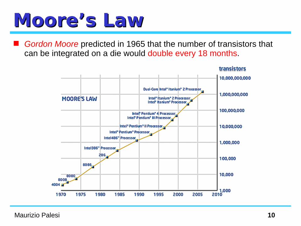
Moore’s LawMoore’s Law Gordon Moore predicted in 1965 that the number of transistors that
can be integrated on a die would double every 18 months.

Maurizio Palesi 11
Semiconductor GrowthSemiconductor Growth

Maurizio Palesi 12
What Makes it HappenWhat Makes it Happen

Maurizio Palesi 13
Processor Power (Watts)Processor Power (Watts)

Maurizio Palesi 14
Intel Microprocessor PerformanceIntel Microprocessor Performance

Maurizio Palesi 15
Device and Context ComplexityDevice and Context Complexity
Exponential increase in device complexityIncreasing with Moore's law (or faster)!
More complex system contextsSystem contexts in which devices are
deployed (e.g. cellular radio) are increasing in complexity
Require exponential increases in design productivity
We have exponentially more transistors!
Com
plexity

Maurizio Palesi 16
Deep Submicron EffectsDeep Submicron EffectsSmaller geometries are causing a
wide variety of effects that we have largely ignored in the past: Cross-coupled capacitancesSignal integrity Resistance Inductance
Design of each transistor is getting more difficult!
DS
M E
ffects

Maurizio Palesi 17
Heterogeneity on ChipHeterogeneity on ChipGreater diversity of on-
chip elementsProcessors Software Memory Analog
More transistors doing different things!
Heterogeneity

Maurizio Palesi 18
Stronger Market PressuresStronger Market Pressures
Decreasing design window
Less tolerance for design revisions
Time-to-market

Maurizio Palesi 19
A QuadrupleA Quadruple
Time-to-market
Co
mp
lexity
DS
M E
ffects
Heterogeneity
Exponentially more complex, greater design risk, greater variety, and a smaller design window!

Maurizio Palesi 20
How Are We Doing?How Are We Doing?
Role of EDA: close the productivity gap
10
100
1,000
10,000
100,000
1,000,000
10,000,000
100,000,000
Tr./S.M
Log
ic t
rans
isto
rs p
er c
hip
(K
)
10
100
1,000
10,000
100,000
1,000,000
10,000,000
Logic Tr./C
hip
1981
1985
1989
1993
1997
2001
2005
2009
58% / Yr. compoundcomplexity growth rate
21% / Yr. compoundproductivity growth rate
Productivitygap

Maurizio Palesi 21
Evolution of Design MethodologyEvolution of Design Methodology
We are now entering the era of block-based design
ASIC/ASSPDesign
SystemBoardIntegration
YesterdayBus Standards,
Predictable, Preverified
TodayVSI Compatible Standards,
Predictable, Preverified
IP/BlockAuthoring
SystemChipIntegration

Maurizio Palesi 22
TrendsTrends A inexpensive 200mm2 die has 75M logic transistors, or 375M SRAM
transistors A 1000mm2 die would have 400M logic transistors
0.05 million8051 microcontroller
0.5 millionMPEG-2 decoder
1.5 millionMPEG-2 encoder
2.8 millionPentium/MMX
0.7 million486DX4
Trans. CountCore Up to 7500 8051 microcontrollers on a single chip!
150 – 750 cores on a single chip
Pentium/MMX

Maurizio Palesi 23
Evolution of SoC PlatformsEvolution of SoC Platforms
General-purposeScalable RISCProcessor• 50 to 300+ MHz• 32-bit or 64-bit
Library of DeviceIP Blocks• Image coprocessors• DSPs• UART• 1394• USB
Scalable VLIWMedia Processor:• 100 to 300+ MHz• 32-bit or 64-bit
Nexperia™System Buses• 32-128 bit
2 Cores: Philips’ Nexperia PNX8850 SoC platform for High-end digital video (2001)

Maurizio Palesi 24
Running Forward…Running Forward…
Four 350/400 MHz StarCore SC140 DSP extended cores
16 ALUs: 5600/6400 MMACS 1436 KB of internal SRAM & multi-
level memory hierarchy Internal DMA controller supports 16
TDM unidirectional channels, Two internal coprocesssors (TCOP
and VCOP) to provide special-purpose processing capability in parallel with the core processors
6 Cores: Motorola’s MSC8126 SoC platform for 3G base stations (late 2003)

Maurizio Palesi 25
What´s Happening in SoCs?What´s Happening in SoCs? Technology: no slow-down in sight!
Faster and smaller transistors: 90 → 65 → 45 nm… but slower wires, lower voltage, more noise!
80% or more of the delay of critical paths will be due to interconnects
Design complexity: from 2 to 10 to 100 cores!Design reuse is essential…but differentiation/innovation is key for winning on the
market! Performance and power: GOPS for MWs!
Performance requirements keep going up…but power budgets don’t!

Maurizio Palesi 26
The Deep Submicron The Deep Submicron EffectsEffects

Maurizio Palesi 27
Communication ArchitecturesCommunication Architectures
Shared busLow areaPoor scalabilityHigh energy consumption
Network-on-ChipScalability and modularityLow energy consumptionIncrease of design complexity
Shared bus
IP IP IP
IP IP IP
IP IP IP
IPIPIP
IP IP IP

Maurizio Palesi 28
Intel’s TeraflopsIntel’s Teraflops 100 Million transistors 80 cores, 160 FP engines Teraflops perf. @ 62 Watts On-die mesh network Power aware design

Maurizio Palesi 29
Terascale vs. ASCI REDTerascale vs. ASCI RED
ASCI Red the first computer to reach a Teraflops of processing (1996) 10,000 Pentium @ 200 MHz 500kW of power (+500kW to keep the room cool)
Terascale the first on-chip solution reaching Teraflop of processing (2006) 80 core chip (VLIW based) 3.16-5.7 GHz 62W-256W

Maurizio Palesi 30
OutlineOutlineTechnology trendsGeneral Design flow
Maurizio Palesi 31
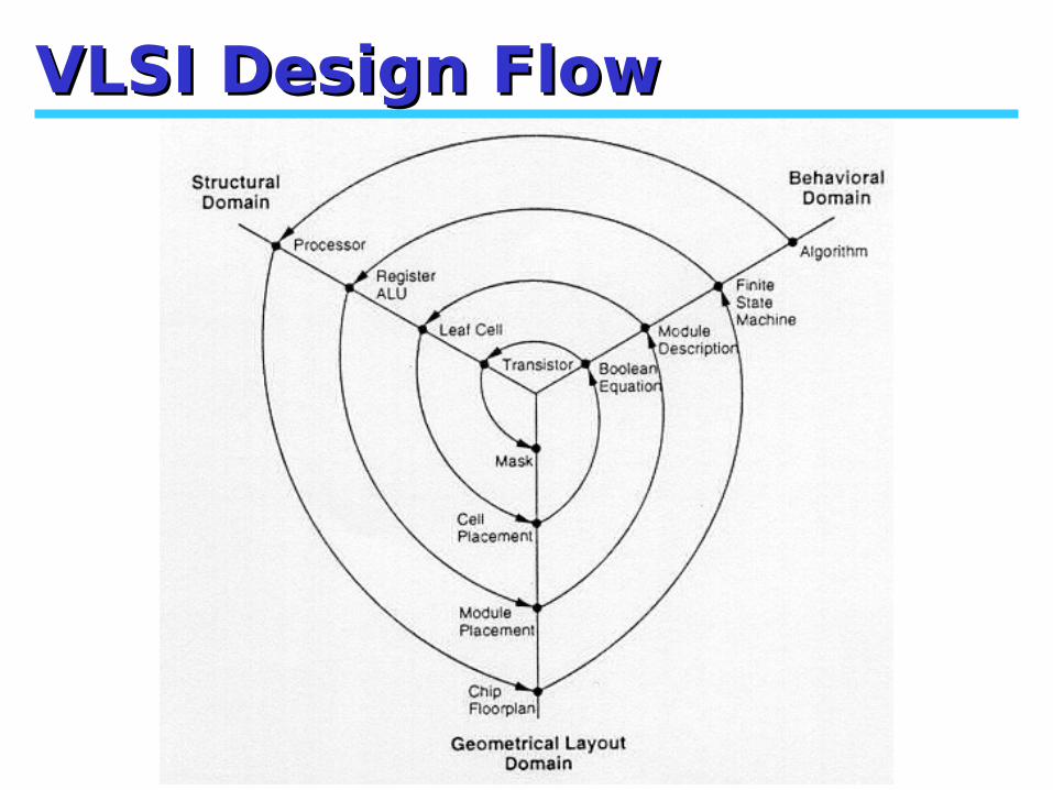
VLSI Design FlowVLSI Design Flow

Maurizio Palesi 32
VLSI Design FlowVLSI Design FlowSimplified ViewSimplified View

Maurizio Palesi 33
VLSI Design FlowVLSI Design FlowSimplified ViewSimplified View
Maurizio Palesi 34
Design HierarchyDesign Hierarchy Involves dividing a module into sub-modules
...and then repeating this operation on the sub-modules until the complexity of the smaller parts becomes manageable
This approach is very similar to the software case Large programs are split into smaller and smaller sections until
simple subroutines, with well-defined functions and interfaces, can be written
A hierarchy structure can be described in each domain separately

Maurizio Palesi 35
4 bit adder Hierarchy4 bit adder HierarchyStructural domain

Maurizio Palesi 36
4 bit adder Hierarchy4 bit adder HierarchyGeometrical domain

Maurizio Palesi 37
GuidelinesGuidelinesRegularityModularityLocality

Maurizio Palesi 38
RegularityRegularity Hierarchical decomposition
should result in not only simple, but also similar blocks, as much as possible
Regularity at all levels of abstractionTransistor level: uniformly sized
transistorsLogic level: identical gate
structures
Regularity usually reduces the number of different modules that need to be designed and verified, at all levels of abstraction

Maurizio Palesi 39
ModularityModularity The various functional blocks which make up the larger
system must have well-defined functions and interfaces Allows that each block or module can be designed
relatively independently from each other All of the blocks can be combined with ease at the end
of the design process, to form the large system The concept of modularity enables the parallelisation of
the design process. It also allows the use of generic modules in various designsThe well-defined functionality and signal interface allow plug-
and-play design

Maurizio Palesi 40
LocalityLocality The internals of each module become unimportant
to the exterior modulesInternal details remain at the local level
Connections are mostly between neighboring modulesAvoiding long-distance connections as much as possible
Time-critical operations should be performed locallyWithout the need to access distant modules or signals

Maurizio Palesi 41
IC Design StepsIC Design Steps
SpecificationsHigh-level
DescriptionFunctionalDescription
BehavioralVHDL, C
StructuralVHDL

Maurizio Palesi 42
IC Design StepsIC Design Steps
Packaging Fabri-cation
PhysicalDesign
TechnologyMapping
Synthesis
SpecificationsHigh-level
DescriptionFunctionalDescription
Placed& RoutedDesign
X=(AB*CD)+ (A+D)+(A(B+C))Y = (A(B+C)+AC+ D+A(BC+D))
Gate-levelDesign
LogicDescription

Maurizio Palesi 43
Circuit ModelsCircuit ModelsA model of a circuit is an abstraction
A representation that shows relevant features without associated details
Circuit Model(few details)
Circuit Model(many details)
Synthesis

Maurizio Palesi 44
Model ClassificationModel Classification

Maurizio Palesi 45
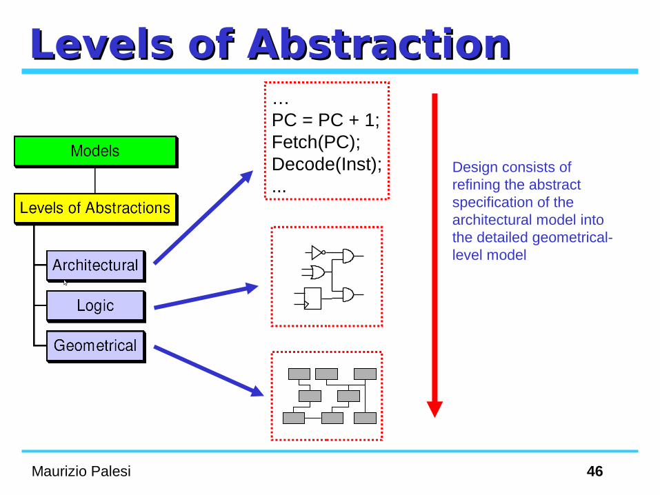
Levels of AbstractionLevels of AbstractionArchitectural
A circuit performs a set of operation, such as data computation or transferHDL models, Flow diagrams, …
LogicA circuit evaluate a set of logic functions
FSMs, Schematics, …
GeometricalA circuit is a set of geometrical entities
Floor plans, layouts, ...
Maurizio Palesi 46
Levels of AbstractionLevels of Abstraction
Design consists of refining the abstract specification of the architectural model into the detailed geometrical-level model
…PC = PC + 1;Fetch(PC);Decode(Inst);...

Maurizio Palesi 47
Views of a ModelViews of a ModelBehavioral
Describe the function of a circuit regardless of its implementation
StructuralDescribe a model as an interconnection of
components
PhysicalRelate to the physical object (e.g., transistors)
of a design

Maurizio Palesi 48
The Y-chartThe Y-chart
Architectural-level
Logic-level
Geometrical-level
Behavioral-view Structural-view
Physical-viewGajski and Kuhn’s Y-chart(Silicon Compilers, Addison-Wesley, 1987)

Maurizio Palesi 49
The Y-chartThe Y-chartBehavioral-view Structural-view
Physical-view
Architecturallevel
Logic level
Geometricallevel
…PC = PC + 1;Fetch(PC);Decode(Inst);...
MULT
ADD
RAM
CTRL
S0
S2
S3 S1

Maurizio Palesi 50
SynthesisSynthesis
Architectural-level
Logic-level
Geometrical-level
Behavioral-view Structural-view
Physical-view
High-level synthesis(or architectural synthesis)
Logic synthesis
Physical design
Assignment to resources Interconnection Scheduling
Interconnection of istances of library cells (technology mapping)
Physical layout of the chip (placement, routing)

Maurizio Palesi 51
Architectural SynthesisArchitectural Synthesis Identify the resources that can implement the operations Scheduling the execution time of the operation Binding them to the resources
Behavioral Architectural-level
Circuit Model
ArchitecturalSynthesis
Control Unit
Datapath

Maurizio Palesi 52
Architectural Syntesis Architectural Syntesis (Example)(Example) Solve numerically (by means of the forward Euler method) the
differential equation y’’+3xy’+3y=0 in the interval [0,a] with step-size dx and initial values x(0)=x; y(0)=y; y’(0)=u.
diffeq {read (x, y, u, dx, a);repeat {
x1 = x + dx;u1 = u - (3*x*u*dx) - (3*y*dx);y1 = y + u*dx;c = x1 < a;x = x1; u = u1; y = y1;
}until(c);write(y);
}
Behavioral View

Maurizio Palesi 53
Architectural Syntesis Architectural Syntesis (Example)(Example) Let us assume that the data path of the circuit contains two resources:
1 multiplier 1 ALU (add, sub, comparison)
Structural ViewMUL ALU
Steering&
Memory
ControlUnit
Data path

Maurizio Palesi 54
Logic SynthesisLogic Synthesis
LogicSynthesis
Gate-level netlist
S0
S2
S3 S1
FSM
…PC = PC + 1;Fetch(PC);Decode(Inst);...
HDL
MULT
ADD
RAM
CTRL
Schematic

Maurizio Palesi 55
Logic Synthesis (Example)Logic Synthesis (Example)
MUL ALUSteering
&Memory
ControlUnit
S1
S2
S3
S4
S5S6
S7
S8
S9
r’
r’
r’
r’
r’
r’
r’
c’r’
*
r
r r
rr
r
r
cr’
Reset state (reading the data)
Writing the data
diffeq { read (x, y, u, dx, a); repeat { x1 = x + dx; u1 = u - (3*x*u*dx) - (3*y*dx); y1 = y + u*dx; c = x1 < a; x = x1; u = u1; y = y1; } until(c); write(y);}

Maurizio Palesi 56
Logic Synthesis (Example)Logic Synthesis (Example)S1
S2
S3
S4
S5S6
S7
S8
S9
r’
r’
r’
r’
r’
r’
r’
c’r’
*
r
r r
rr
r
r
cr’
Stateλ δr
c
Fro
m s
teer
ing
& m
em
ory
mod
ule
To
ste
erin
g&
me
mor
y m
od
ule
LogicSynthesis

Maurizio Palesi 57
OptimizationOptimization Quality measures
Performance Combinational logic circuits
– Propagation delay through the critical path [sec]
Synchronous sequential circuits– Cycle time [sec]– Latency [clock cycles]– Execution time = Latency*Cycle time– Throughput (for pipeline organization)
Area Logic gates, registers, wiring
Power Energy
– Battery life, system weight, ...
Power– Packaging, reliability, cost, ...

Maurizio Palesi 58
OptimizationOptimization
MUL ALUSteering
&Memory
ControlUnit
diffeq { read (x, y, u, dx, a); repeat { x1 = x + dx; u1 = u - (3*x*u*dx) - (3*y*dx); y1 = y + u*dx; c = x1 < a; x = x1; u = u1; y = y1; } until(c); write(y);}
x y u dxa
+
x1
* 3
3x*
udx
*
3xudx
*
3
3y
*
3ydx
-
-
u
dx
<
c
u1
+
y
y1
6 clock cycles

Maurizio Palesi 59
diffeq { read (x, y, u, dx, a); repeat { x1 = x + dx; u1 = u - (3*x*u*dx) - (3*y*dx); y1 = y + u*dx; c = x1 < a; x = x1; u = u1; y = y1; } until(c); write(y);}
x y u dx
a
+*
3
*
3x x1 udx
<
c
*
3xudx
*
3
3y
*
3ydx
-
u-3xudx
-
u1
+
y
y1
Optimization
MUL ALUSteering
&Memory
ControlUnit
4 clock cycles
MUL ALU

Maurizio Palesi 60
Design SpaceDesign Space Parameters
# of ALU (max 2), # of Multiplier (max 2)
Design space System A = 1 alu, 1 multiplier System B = 1 alu, 2 multiplier System C = 2 alu, 1 multiplier System D = 2 alu, 2 multiplier
Let us assume Multiplier = 5 units of area ALU = 1 unit of area Control Unit + Steering logic = 1 unit
of area
Area
Latency(clock cycles)
1 2 3 4 5 6 7
151413121110
987
BD
CA
DominatedPareto points