vision-based finger detection, tracking, and event - mdpi.com
TRANSCRIPT

Sensors 2011, 11, 6868-6892; doi:10.3390/s110706868
sensors ISSN 1424-8220
www.mdpi.com/journal/sensors
Article
Vision-Based Finger Detection, Tracking, and Event
Identification Techniques for Multi-Touch Sensing and Display
Systems
Yen-Lin Chen 1, Wen-Yew Liang
1, Chuan-Yen Chiang
2, Tung-Ju Hsieh
1, Da-Cheng Lee
1,
Shyan-Ming Yuan 2 and Yang-Lang Chang
3,*
1 Department of Computer Science and Information Engineering, National Taipei University of
Technology, 1, Sec. 3, Chung-hsiao E. Rd., Taipei 10608, Taiwan;
E-Mails: [email protected] (Y.-L.C.); [email protected] (W.-Y.L.);
[email protected] (T.-J.H.); [email protected] (D.-C.L.) 2 Department of Computer Science, National Chiao Tung University, 1001 University Road,
Hsinchu 30050, Taiwan; E-Mails: [email protected] (C.-Y.C.); [email protected] (S.-M.Y.) 3 Department of Electrical Engineering, National Taipei University of Technology, 1, Sec. 3,
Chung-hsiao E. Rd., Taipei 10608, Taiwan
* Author to whom correspondence should be addressed; E-Mail: [email protected];
Tel.: +886-2-2771-2171 ext. 2156.
Received: 12 May 2011; in revised form: 20 June 2011 / Accepted: 20 June 2011 /
Published: 1 July 2011
Abstract: This study presents efficient vision-based finger detection, tracking, and event
identification techniques and a low-cost hardware framework for multi-touch sensing and
display applications. The proposed approach uses a fast bright-blob segmentation process
based on automatic multilevel histogram thresholding to extract the pixels of touch blobs
obtained from scattered infrared lights captured by a video camera. The advantage of this
automatic multilevel thresholding approach is its robustness and adaptability when dealing
with various ambient lighting conditions and spurious infrared noises. To extract the
connected components of these touch blobs, a connected-component analysis procedure is
applied to the bright pixels acquired by the previous stage. After extracting the touch blobs
from each of the captured image frames, a blob tracking and event recognition process
analyzes the spatial and temporal information of these touch blobs from consecutive frames
to determine the possible touch events and actions performed by users. This process also
refines the detection results and corrects for errors and occlusions caused by noise and
OPEN ACCESS

Sensors 2011, 11
6869
errors during the blob extraction process. The proposed blob tracking and touch event
recognition process includes two phases. First, the phase of blob tracking associates the
motion correspondence of blobs in succeeding frames by analyzing their spatial and
temporal features. The touch event recognition process can identify meaningful touch
events based on the motion information of touch blobs, such as finger moving, rotating,
pressing, hovering, and clicking actions. Experimental results demonstrate that the
proposed vision-based finger detection, tracking, and event identification system is feasible
and effective for multi-touch sensing applications in various operational environments
and conditions.
Keywords: multi-touch sensing; computer vision; finger detection; finger tracking;
multi-touch event identification
1. Introduction
Multi-touch sensing systems have attracted a lot of attention in current human-computer interaction
applications [1]. The first prototype multi-touch sensing system was developed at the University of
Toronto at 1982 [2]. Bell Labs then designed a touch sensing and display system for graphical
user interface applications [3] in 1984. Many well-known commercial products with multi-touch
technologies have recently become in everyday life, such as the Apple iPhone [4], Apple Macbook
Air [5], and Microsoft Surface Computer [6]. A multi-touch interface provides much more flexibility
and convenience than traditional interfaces such as keyboards and mouses by allowing user to directly
and intuitively interact with digital content and media through hand and finger actions on the
display surfaces.
Some consumer systems, such as the touch screens on electronic check-out machines, use resistive
surfaces for touch sensing. These resistance-based systems are cheap to implement, but cannot provide
sufficient sensing accuracy and clarity to support more sophisticated user operations and commands.
Systems based on capacitive technologies can provide more accurate sensing results using multiple
touch contacts on the screen [7-9]. However, systems based on capacitive sensing require some
specific facilities, such as specified receivers for detecting the signals emitted from the transmitter
under the display surface. This significantly limits the possible movements and operations of many
user applications. Infrared LED based systems [10-12] use sets of pairing transmitters and receivers of
infrared LEDs to construct a two dimensional sensing array on the back of a screen. This type of
system can sense touch contact through blocked infrared lights when a user’s finger touches a given
cross point of a horizontal path and a vertical path of infrared lights in the sensing array. Nevertheless,
the touch sensing accuracy of infrared LED based systems relies heavily on the number and density of
transmitters and receivers, and the structural arrangement of the sensing array. Thus, their applicability
and flexibility are limited when large display screens must accommodate more users and more
simultaneous touch operations.
Due to the falling costs and growing power of computers, technologies based on computer vision
are becoming popular solutions for many object detection, tracking, and analysis applications in

Sensors 2011, 11
6870
real-life environments, such as the detection and recognition of people, vehicles, lanes, animals,
obstacles, etc… [13-20]. For multi-touch sensing applications, hands and fingers are the salient objects
captured from the cameras in the computer vision problems. Thus, camera-based techniques have
attracted a lot of attention in multi-touch sensing applications [21-30]. Several camera-based systems
apply computer vision techniques to detect and track finger locations via overhead-mounted
cameras [21-24]. Letessier and Berard [21] presented a single overhead camera system to capture
finger positions on a display surface. The single overhead camera approach has obvious difficulties in
accurately detecting finger contacts on the display surface. Systems based on paired overhead
cameras [22,23] use stereo vision and depth features to provide more precise detected finger contacts
with the display surface. However, these systems still suffer significant self-occlusion problems when
multiple fingers are simultaneously pressed on the surface. These multiple camera systems also require
additional costs in camera calibration before use. The PlayAnywhere system in [24] adopts an infrared
camera and uses the shape of a finger shadow to refine the touch detection results. However, when
multiple finger contacts are pressed on the surface and the pointing directions of these fingers are not
perpendicular to the direction of the infrared light source, the shadow shape features become unreliable
due to occlusions and lighting effects. Chung et al.’s MirrorTrack system [25,26] uses three cameras
side-mounted parallel to the glossy display surface to capture finger contacts on the surface in three
different orientations. This system provides more accurate detection results for finger contact points.
However, due to the restricted capturing fields of the side-mounted cameras, more cameras are
required to capture sufficient image features of the hands of the users in the surface area. Thus, the
costs of multiple cameras and the complexity of calibrating multiple cameras limit the applicability
and convenience of side-mounted camera based systems.
Researchers have recently develop rear-mounted camera based systems for consumer multi-touch
sensing applications [6,27,28]. The Diffused Illumination (DI) technique adopted in Microsoft’s
Surface computer [6] product uses one infrared emitter, four infrared cameras, and a projector
(Figure 1). This system emits infrared lights onto a screen, and once the user touches the screen, the
four cameras capture the reflected infrared lights and produce bright blobs. These bright blobs are the
small spots of reflected lights formed by the users’ touch contacts, and can be detected and processed
via some image processing techniques. The HoloWall system [27] uses a glass wall combined with a
rear-projection sheet to capture the scattered infrared lights caused by finger touches. This technique is
more inexpensive and easy to implement. However, when finger touches occur, the infrared lights may
be scattered wide, making it difficult for the camera to capture sufficient lights to identify the touch
blobs of interest. Moreover, this technique is sensitive to ambient lighting effects. Han [28] proposed a
Frustrated Total Internal Reflection (FTIR) technique, which is inexpensive and easy to implement.
The FTIR technique uses a specialized acrid panel as the display surface, an infrared emitter, a
projector, and a video camera. The FTIR technique uses infrared LEDs to emit infrared lights into the
acrid display panel from one side to another side. The infrared lights are totally reflected within the
acrid panel until finger touches scatter the lights. These scattered lights can then be captured by a video
camera mounted under or behind the acrid display panel and imaged as bright blobs. These bright
blobs can also be detected and recognized as finger touches via some image processing techniques to
obtain possible interactive actions of the users.

Sensors 2011, 11
6871
Figure 1. (a) A Microsoft Surface Computer. (b) The structure of Microsoft Surface (1 is
the transparent panel, 2 is the infrared source, 3 is a infrared camera, 4 is the projector).
(a) (b)
The FTIR technique offers great flexibility in simultaneously detecting a large number of multiple
touch contacts with high spatial and temporal frequencies. Other camera-based systems, such as
overhead-camera-based systems, are unable to detect and process multiple nearby touches or provide
some advanced interacting operations. However, because each touch contact detected by the FTIR
appears as an independent event, post-processing is necessary to determine whether a set of touch
contacts detected at different time belong to the same user’s touch trajectory. As the number of user
grows and their corresponding touch actions increase, the determination of user operations from a large
number of individual touch detections becomes increasingly difficult. The touch detection accuracy of
the FTIR technique may be affected by spurious infrared noises under poor lighting conditions.
To overcome the above-mentioned problems of the FTIR technique, this study presents efficient
vision-based touch finger detection, tracking, and event identification techniques and a low-cost
hardware framework for multi-touch sensing and display applications. First, a fast bright-blob
segmentation process based on automatic multilevel histogram thresholding extracts the pixels of
touch blobs formed by scattered infrared lights in the image sequences captured by a video camera.
The advantage of this automatic multilevel thresholding approach is its robustness and adaptability
when dealing with various ambient lighting conditions and spurious infrared noises. A connected-
component analysis procedure is then applied to the bright pixels obtained by the previous stage to
extract the connected-components of these touch blobs. Given the touch blobs extracted from each of
the captured frames, a blob tracking and event recognition process analyzes the spatial and temporal
information of these touch blobs from consecutive frames to determine possible touch events. This
process also refines the detection results and corrects for errors and occlusions caused by noise and
errors during the blob extraction processes. The proposed blob tracking and touch event recognition
process includes two phases. The blob tracking phase first associates the motion correspondence of
blobs in succeeding frames by analyzing their spatial and temporal features. The touch event
recognition phase then identifies meaningful touch events and gestures from the motion information of
touch blobs (such as finger moving, clicking, and zooming actions). The resulting touch event and
gestures represent various interactive commands for controlling and manipulating objects on the
display interface. Experimental results demonstrate that the proposed vision-based finger detection,

Sensors 2011, 11
6872
tracking, and event identification system is feasible and effective for multi-touch sensing applications
in various operational environments and illumination conditions.
2. Hardware Structure Design
Frustrated total internal refection (FTIR) [28] is based on the phenomenon of the total internal
reflection of infrared lights within an acrylic board (Figure 2). Figure 3 illustrates the structure of the
proposed multi-touch sensing interface, showing that the infrared lights are emitted into the inner layer
of a transparent acrylic board with a proper angle via the side-mounted infrared LEDs. Without
exterior interference, the lights pass through the inner layer of the board due to total reflection
phenomenon. When the top side of the surface is pressed by an object with a relatively high
refractive rate, such as a finger, some of the infrared light at the contact point is reflected and
diffused to the bottom of the board. The diffused infrared lights can be captured by a video camera
mounted below the acrylic board and detected as bright blobs. These bright blobs can then be
processed using image segmentation and recognition techniques to locate and analyze their
appearance and motion features, and generate interactive commands for various applications.
Figure 2. Total internal reflection in an acrylic board.
Figure 3. The structure of the proposed multi-touch sensing interface.
This study presents a low-cost solution for multi-touch sensing and display based on the FTIR
concept. Figure 4 depicts the design framework of the proposed multi-touch sensing and display
device. A conventional LCD displayer serves as the display interface. Multi-touch sensing modules are
placed in front of the LCD displayer for sensing and obtaining the user finger touching blobs at the
input interface. As Figure 4 illustrates, the LCD displayer is split into the following parts and installed
Sensors 2011, 11
6873
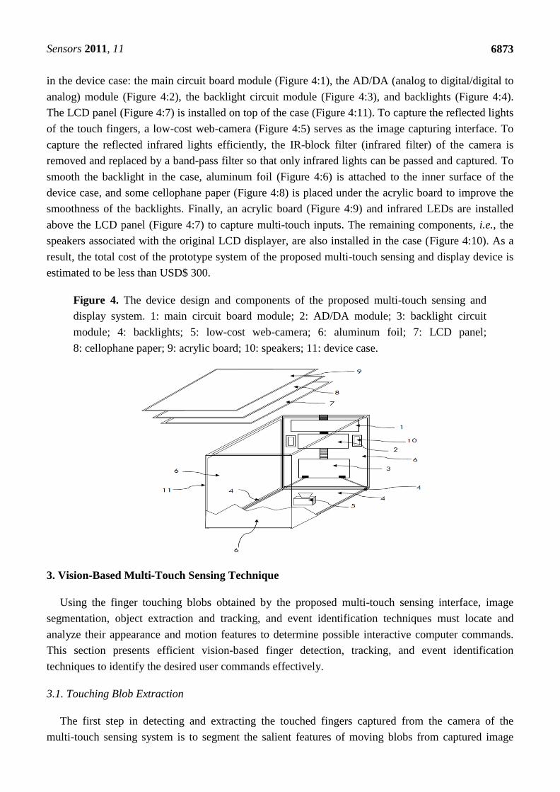
in the device case: the main circuit board module (Figure 4:1), the AD/DA (analog to digital/digital to
analog) module (Figure 4:2), the backlight circuit module (Figure 4:3), and backlights (Figure 4:4).
The LCD panel (Figure 4:7) is installed on top of the case (Figure 4:11). To capture the reflected lights
of the touch fingers, a low-cost web-camera (Figure 4:5) serves as the image capturing interface. To
capture the reflected infrared lights efficiently, the IR-block filter (infrared filter) of the camera is
removed and replaced by a band-pass filter so that only infrared lights can be passed and captured. To
smooth the backlight in the case, aluminum foil (Figure 4:6) is attached to the inner surface of the
device case, and some cellophane paper (Figure 4:8) is placed under the acrylic board to improve the
smoothness of the backlights. Finally, an acrylic board (Figure 4:9) and infrared LEDs are installed
above the LCD panel (Figure 4:7) to capture multi-touch inputs. The remaining components, i.e., the
speakers associated with the original LCD displayer, are also installed in the case (Figure 4:10). As a
result, the total cost of the prototype system of the proposed multi-touch sensing and display device is
estimated to be less than USD$ 300.
Figure 4. The device design and components of the proposed multi-touch sensing and
display system. 1: main circuit board module; 2: AD/DA module; 3: backlight circuit
module; 4: backlights; 5: low-cost web-camera; 6: aluminum foil; 7: LCD panel;
8: cellophane paper; 9: acrylic board; 10: speakers; 11: device case.
3. Vision-Based Multi-Touch Sensing Technique
Using the finger touching blobs obtained by the proposed multi-touch sensing interface, image
segmentation, object extraction and tracking, and event identification techniques must locate and
analyze their appearance and motion features to determine possible interactive computer commands.
This section presents efficient vision-based finger detection, tracking, and event identification
techniques to identify the desired user commands effectively.
3.1. Touching Blob Extraction
The first step in detecting and extracting the touched fingers captured from the camera of the
multi-touch sensing system is to segment the salient features of moving blobs from captured image

Sensors 2011, 11
6874
sequences. Figure 5 shows a sample of the captured image from the proposed sensing interface.
Performing blob detection and recognition for multi-touch display applications requires an effective
approach for correctly and rapidly locating and extracting the salient features of blobs under various
illumination conditions on the sensing interface. This way enables the efficient extraction and
segmentation of the object regions of touching fingers. Therefore, this section presents a fast bright-object
segmentation process based on automatic multilevel histogram thresholding. The proposed method
extracts the object pixels of finger touching blobs from captured image sequences.
Figure 5. Example of the captured image from the proposed sensing interface.
The first task of the image-processing module in the proposed multi-touch sensing system is to
extract the object pixels of finger touching blobs from the captured sensing image sequences to
facilitate further rule-based analysis of the touch events and user-activated commands. To reduce the
computation cost of extracting finger touching blobs, the gray intensity image, i.e., the Y-channel, of
the image is first extracted by performing a RGB to Y transformation. To extract finger blob objects
from a given transformed gray-intensity image, finger blob pixels must be separated from other
uninteresting object pixels of different illumination features. The proposed approach uses the
discriminant criterion to measure separability among the decomposed images with dissimilar objects.
Otsu [31] was the first to use the discriminant criterion for the bi-level image thresholding. Otsu
determined the optimal threshold by maximizing the between-class variance between dark and bright
regions of the image. This method is ranked as the most effective bi-level thresholding method for
image segmentation [32]. Extensive research studies based on this optimal thresholding methodology
have also been efficiently applied to various object segmentation and analysis applications, such as
text extraction for document image analysis [33,34], biofilm image segmentation [35,36], and vehicle
detection applications [20]. However, as the number of desired thresholds of different objects
increases, the computational cost needed to obtain the optimal threshold values increases significantly,
and the search to achieve the optimal value of the criterion function becomes particularly exhaustive.
An effective multilevel thresholding technique is needed to automatically determine the appropriate
number of thresholds to extract touch blob regions from multi-touch sensing image sequences. Using
the properties of discriminant analysis, our previous research presents an effective automatic multilevel
thresholding technique for image segmentation [37]. This technique extends and adopts the properties
of discriminant analysis to multilevel thresholding. By evaluating the separability using the
discriminant criterion the number of objects, into which the image frame should be segmented, can be
automatically determined to accordingly extract salient objects of interest. As a result, the pixel regions

Sensors 2011, 11
6875
of touch blobs can be appropriately extracted from other uninteresting objects contained in the multi-
touch sensing images.
The proposed touch blob segmentation process is briefly described as follows. Let fi denote the
observed occurrence frequencies (histogram) of all pixels in a given captured image I, with a given
grayscale intensity i, and let N denote the total number of pixels in the image I, and can be given by
0 1 1... LN f f f , where L is the number of grayscale intensities in the histogram, and represents
the brightest grayscale value, i.e., 255 in our vision system. Hence, the normalized probability iP of
one pixel having a given grayscale intensity i can be denoted as:
i iP f N , where 0iP , 1
0
1L
i
i
P
(1)
If the image I consists of multiple objects, it is possible to extract pixels of bright object regions
(i.e., touch blobs in the sensing images) from those of other homogeneous object regions by
partitioning pixels into a suitable number of classes, each of which consists of one respective
homogenous object region. Thus, a multiple threshold set T comprised of k thresholds, i.e.,
T = 1,..., ,...,n kt t t can be determined to segment pixels of the image I into k+1 homogenous pixel
classes. These segmented pixel classes are represented by 0C = 10,1,..., t ,…,
nC = 11, 2,...,n n nt t t , …, kC = 1, 2,..., 1k kt t L . Here, the class
kC consists of pixels of
bright blob objects of interest, that is, the finger touch blobs in the sensing images.
This study uses several statistical measures for performing this multilevel thresholding process. The
between-class variance, denoted by BCv , an effective criterion for evaluating the results of
segmentation, is utilized to measure the separability among all pixel classes. This criterion is expressed as:
2
0
( ) ( )k
BC n n T
n
v w
T (2)
where nw is the cumulative probability mass function of class
nC , and n denotes the mean of pixels
in class nC . The within-class variance, denoted by
WCv , of all segmented classes of pixels is:
2
0
( )k
WC n n
n
v w
T (3)
The total variance Tv and the overall mean
T of pixels in the image I are:
12
0
( )L
T T i
i
v i P
, and
1
0
L
T i
i
iP
(4)
where k is the number of selected thresholds to segment pixels into 1k classes, and n represents
the standard deviation of pixels in class nC . The statistical terms
nw , n , and
n of pixels in class nC
are computed respectively as:
1
1
n
n
n i
t
i t
w P
,
1
1n
i
n
n
nt
i t
iP
w
, and
12
12
( )n
n
i n
n
n
t
i t
P i
w
(5)
where a dummy threshold 0 0t is used to simplify the expression of equation terms.

Sensors 2011, 11
6876
The aforementioned statistical measures can be used as a measure of separability, among all
existing pixel classes, decomposed from the original image I. This study uses this concept as a criterion
of automatic image segmentation, denoted by the ―separability factor‖ — SF , which is defined as:
( ) 1 ( ) BC T WC Tv v v vSF T T (6)
where Tv is the total variance of the grayscale values of the image I and serves as the normalization
factor in this equation. The SF value reflects the separability among all existing classes, and the SF
value lies within the range 0,1 . The segmentation results of homogeneous objects can be optimized
by maximizing the SF value. Observation of the terms comprising ( )WCv T indicate that if the pixels in
each class are broadly spread, i.e., the contribution of the class variance 2 n is large, then the
corresponding SF measure becomes small. Hence, when SF approaches 1.0, all classes of grayscale
values decomposed from the original image I are ideally and completely separated. Previous research
presents a detailed derivation of this property [37].
Using the above-mentioned statistical discriminant measure, the bright object segmentation process
can be implemented by recursively segmenting homogeneous objects from the multi-touch sensing
image I until the brightest objects of interest are clearly obtained, regardless of the number of existing
objects and various illuminated conditions. This segmentation process is conducted by recursively
thresholding the grayscale values of the image I until the SF measure is large enough (i.e., SF
approaches 1.0) to indicate that the appropriate discrepancy among the resulting classes of grayscale
intensities is achieved. Thus, the bright objects of touch blobs are clearly segmented into a separate
thresholded sensing image. Through the above mentioned properties, this objective can be reached by
minimizing the total within-class variance ( )WCv T . This can be achieved by a recursive partition
strategy that selects the pixel class with the maximal within-class variance contribution ( 2n nw ),
denoted by pC . The bi-class partition procedure, as described in [37], is performed on each determined
pC into two more classes in each recursion. This partition process is recursively performed until the
separability among all pixel classes becomes satisfactory, i.e., the SF measure approximates a
sufficiently large value:
SThSF (7)
This study sets the value of the separability measure threshold STh as 0.92 based on the
experimental analysis in [37] to yield satisfactory object segmentation results under different
illumination conditions. The resulting thresholded bright objects of interest, i.e., the obtained brightest
pixel class Ck, extracted by this recursive thresholding strategy are ensured to achieve maximum
separation. This approach achieves satisfactory segmentation results for these objects using the fewest
recursions. Previous research provides detailed descriptions of this multilevel thresholding
technique [37].
To obtain blobs of potential touching fingers from the extracted bright object plane, a
connected-component extraction process [38] is performed on the bright object plane to label and
locate the connected-components of the bright blobs. Extracting the connected-components reveals the
meaningful features of the location, size, and pixel distribution associated with each touching blob.
Figure 6(a) shows that, after performing the touching blob extraction process, the pixels of bright blobs
are efficiently segmented into thresholded object planes from the captured sensing image in Figure 5.

Sensors 2011, 11
6877
Figure 6(b) shows the connected-components of the bright blobs obtained from Figure 6(a). The
proposed blob tracking and touch event recognition approach analyzes and processes the blobs of
potential touching fingers acquired in each image of video sequences captured from the vision system
to identify possible touch events, as described in the following subsections.
Figure 6. Results of performing the touching blob extraction process on the captured image
in Figure 5. (a) Bright blobs extracted from Figure 5. (b) The connected-components of the
bright blobs obtained from Figure 6(a).
(a) (b)
3.2. Blob Tracking and Touch Event Identification
The proposed touching blob extraction method effectively obtains the blobs of the touching fingers
in each image frame captured from the proposed sensing interface. In multi-touch applications, users
perform various gestures by moving their fingers to issue their desired control commands. These
gestures are mostly formed by the movements and actions of one, two, or more blobs of touching
fingers. Since the complete features of touching gestures may not be immediately identified from
single image frames, a tracking procedure for the blobs of touching fingers must be applied to analyze
the information of moving blobs to recognize touching gestures from consecutive image frames.
During the tracking process, the spatial-temporal information of moving blobs can be used to refine the
detection results and correct the errors due to occlusions caused by noise and interference during
the blob object segmentation process. The tracking information of blobs can be utilized to determine
and recognize meaningful touch events, such as finger moving, rotating, pressing, hovering, and
clicking actions. The proposed blob tracking and touch event recognition process includes two phases.
The blob tracking phase first associates the motion of blobs in succeeding frames by analyzing their
spatial and temporal features. The touch event recognition phase then identifies possible touch events
based on the tracked motion information of blobs.
3.2.1. Blob Tracking Process
The spatial-temporal features of the blob regions of touching fingers make it possible to
progressively refine and correct the detection results of the moving blobs by associating them in
sequential frames. Therefore, this study presents a tracking process for analyzing the motion features
of the detected touch blobs to address the above-mentioned problems. Moreover, the tracking

Sensors 2011, 11
6878
information of the moving blobs can be applied to the following touch event recognition process to
determine possible touch events from the tracked motion information of the blobs.
When the vision system initially detects the blob of a given finger, it creates a tracker to associate this
blob with those from the same finger in subsequent frames based on their contiguous spatial-temporal
features. The features used in the tracking process are described and defined as follows:
(1) t
iP denotes the ith
detected touch blob appearing in tth
frame captured by the sensing system
(2) The position of the blob t
iP employed in the tracking process is represented by its centroid, and
can be simply computed by:
( ) ( ) ( ) ( ),
2 2
t t t tt i i i i
i
l P r P t P b PP
(8)
where ( )t
il P , ( )t
ir P , ( )t
it P , and ( )t
ib P denote the left, right, top, and bottom coordinates of the blob t
iP , respectively
(3) The tracker t
iTP represents the trajectory of the blob t
iP that has been tracked in a set of
sequential frames 1 to t, and is defined as:
1 2, ,...,t t
i i i iTP P P P (9)
(4) Let t
id represent the path deviation feature of a given blob t
iP at the tth
frame captured by the
vision system, which is:
2 1 2 1 1( , , ) ( , )t t t t t t t t
i i i i i i i id P P P P P P P (10)
where the function is the path coherence function of t
iP , and the vector 1t t
i iP P reveals the
position deviation of t
iP from the t − 1th
frame to the tth
frame.
(5) The path coherence function can then be determined by computing the deviation formula of
the motion vectors 2 1t t
i iP P and 1t t
i iP P in two succeeding frames. The path coherence function
consists of two deviation terms. The first term reveals the directional deviation formed by 2 1t t
i iP P
and 1t t
i iP P , while the second term represents the corresponding velocity deviation between them.
This tracking process assumes that the trajectories of moving fingers are mostly smooth and plain,
and thus their corresponding path coherences should reflect smooth motion in both directional and
velocity deviations. The path coherence function can thus be derived and computed as:
2 1
2 1 1
1 2 2 1 1
2 1 1
1 22 1 1
( , , )
( , ) ( , )(1 cos ) 1 2
( , ) ( , )
1 1 2,
t t t
i i i
t t t t
i i i i
t t t t
i i i i
tt t t t
ii i i i
t t t t
i i i i
P P P
d P P d P Pw w
d P P d P P
PP P P Pw w
P P P P
2 1 1
2 1 1,
t t t
i i i
t t t t
i i i i
P P P
P P P P
(11)
(6) Hence, the path deviation of a given blob iP corresponding to its tracker t
iTP , denoted as
( )t
i iD TP , can be computed and obtained by:

Sensors 2011, 11
6879
1
2
nt t
i i i
t
D TP d
(12)
(7) Accordingly, when m blobs are detected within a time slot of image frames, the overall tracker
deviation function D of the tracker sets of these m blobs can be obtained by:
1
m
i
i
DD (13)
Based on the above-mentioned definitions utilized in the tracking process, the trackers formed by
the detected touch blobs in the sequential images can be determined by minimizing the overall tracker
deviation function D associated with these detected blobs. Accordingly, in each recursion of the
tracking process for a incoming frame t, the newly detected touch blobs appearing in this incoming
frame, denoted by 1,...,t t
iP i k P , will be analyzed and associated with the tracker sets of touch
blobs that have already been tracked in the previous frames t − 1 and t − 2, denoted by
1 1 1,...,t t
jTP j k TP and 2 2 1,...,t t
jTP j k
TP , respectively. Thus, the current tracker set
of the finger blobs tTP can be updated by minimizing the overall tracker deviation function D
associated with the sets of finger blobs in tP , 1tTP , and 2t
TP .
3.2.2. Touch Event Identification and Occlusion Resolution Process
The proposed system can efficiently obtain trackers that reflect the spatial-temporal information of
the detected finger blobs by applying the above-mentioned tracking process to the detected finger
blobs. By analyzing the spatial-temporal information of the tracked finger blobs, the changing
processes of the amount of finger blobs and the variation of the finger blob trajectories can reflect
possible touching events of commands, or some occlusions of blob trackers caused by the blob
extraction and tracking process. Such touch events may be: (1) When users press down or lift up their
fingers, they change the number of finger blobs; (2) When users conduct a single-click or double-click
action using their fingers, the corresponding finger blobs will quickly disappear and re-appear; (3)
When users activate a zooming action by moving two fingers apart or close together along a straight
line, the motion trajectories of a pair of finger blobs will form a straight line with increasing or
decreasing distances; (4) Users may move two or more fingers close to each other for a while then split
their fingers, or vice versa. In this case, the corresponding finger blobs might be occluded for a while
during the blob extraction and tracking process. Using the trackers of the finger blobs t t
iTP TP
obtained by the blob tracking process, the event analysis and occlusion resolution process can
determine the corresponding touch events and resolve the occlusions of each finger blob tracker based
on the spatial-temporal information of the tracked finger blobs.
To perform the touch event analysis and occlusion resolution process on the tracked finger blobs,
the following spatial-temporal overlapping score of two finger blobs t
iP and t
jP, detected at two
different times t and t’, is defined as:
( , )( ), ( )
t t
i jt t
o i j t t
i j
A P PS P P
Max A P A P
(14)
where t t
i jA P P
represents the area of intersection of t
iP and t
jP.

Sensors 2011, 11
6880
While the finger blobs are being tracked, the touch event analysis and occlusion resolution process
will determine the associated possible event states based on their spatial-temporal features. In the
proposed system, the tracked finger blobs might be in one of seven possible event states, and the touch
event analysis and occlusion resolution process will activate different touch events or operations
according to the given event states of the tracked finger blobs in each given period. The proposed
system uses the following tracking event states and associated actions for the tracked finger blobs:
(1) Update: When the number of tracked finger blobs t t
iTP TP in the current frame is exactly
equal to the number of those 1 1t t
jTP TP in the previous frame, then no touch event happens. In
this case, the process simply updates the set of tracked finger blobs t t
iTP TP in the current frame
with the ones 1 1t t
jTP TP in the previous frame according to the updated trackers obtained by the
blob tracking process.
(2) Appearing / Finger Pressing-down: If the newly appearing finger blobs t t
iP P do not match
any 1 1t t
jTP TP in the previous period, the user may have pressed additional fingers on the panel.
In this case, new trackers are created for these finger blobs and appended to the updated set tTP for
the next recursion of the blob tracking process.
(3) Disappearing/Finger Lifting-up: Some existing trackers of finger blobs 1 1t t
jTP TP do not
match any newly detected finger blobs t t
iP P . This situation might occur when the user lifts up
some fingers from the panel. A tracked finger blob may temporarily disappear or become occluded
in some frames, and will soon re-appear in subsequent frames. This can happen when the user wants
to activate a clicking command. To prevent these finger blobs from being regarded as newly-
appearing finger blobs, the system retains their trackers through the next five frames to help identify
possible clicking events. If a tracker of finger blob 1t
jTP does not matched any finger blobs t t
iP P
for more than five succeeding frames, then this finger blob will be determined to have disappeared
and its tracker will be removed from the tracker set tTP in the following frames.
(4) Clicking Action: If a tracked finger blob 1 1t t
jTP TP suddenly disappears for a short period
(within five frames) and then quickly re-appears, or repeats this event again, in a hovering position
within a specific area, the user may be performing a single or double clicking operation. Therefore,
if any finger blobs t k t k
iP P in the following short period of five frames (i.e., k = 0,1,…,5)
quickly re-appear, they may successfully match 1 1t t
jTP TP by the following matching condition:
1,t k t
o i j mS P TP (15)
To identify clicking events accurately, the threshold m should have reasonable spatial-temporal
coherences for t k
iP and 1t
jTP to determine if they are associated with the same finger clicks. This
study uses a value of 0.25m to obtain satisfactory click event identification results.
(5) Merging: If a detected finger blob t
iP in the current frame matches multiple tracked finger blobs 1t
jTP ,
1
1
t
jTP
…, 1t
j nTP
(Figure 7), this indicates that the user’s formerly separate fingers are
currently touching. Therefore, the matching condition [Equation (15)] of the detected finger blob t
iP
with the tracked finger blobs 1t
jTP ,
1
1
t
jTP
…, 1t
j nTP
will be respectively checked, and any tracked
finger blobs that satisfy the matching condition will be merged into a single tracker of the renewed t
iTP , and the tracker set tTP will be updated.

Sensors 2011, 11
6881
Figure 7. Illustration of a merging event.
(6) Splitting: If one tracked finger blob 1t
jTP in the previous frame is split into blobs t
iP , 1
t
iP …, t
i mP in the current frame (Figure 8), then the user’s formerly closed fingers are becoming separated.
Thus, the matching condition (Equation (15)) between this tracked finger blob 1 1t t
jTP TP is
evaluated with the newly detected finger blobs t
iP , 1
t
iP …, t
i mP that are possibly associated with the
split fingers. If the newly detected blobs having the highest matching score oS with
1t
jTP are still
associated with the updated tracker t
jTP , the remaining newly detected blobs that match 1t
jTP will
be marked as having split from the same closed finger set and will begin their own new trackers t
jTP , 1
t
jTP …, 1
t
j mTP in the updated tracker set tTP .
Figure 8. Illustration of a splitting event.
(7) Zooming Action: When a pair of two tracked finger blobs t
iTP and t
jTP move close together, or
move from being close together to far apart along a straight line, this may indicate the user is
zooming out or zooming in (as depicted in Figure 9(a) and Figure 9(b), respectively). When the
trajectories of a pair of two distant finger blobs t
iTP and t
jTP move close to each other along a
straight line and eventually result in a merging event, then a zooming out event is identified. When a
touched blob of two fingers starts with a splitting event into a pair of two blobs t
iTP and t
jTP , and
they move apart along a straight line, then a zooming in event is identified
Figure 9. Illustrations of zooming action events. (a) Zooming out event. (b) Zooming
in event.
(a) (b)

Sensors 2011, 11
6882
After identifying the touch events based on the moving blobs in the video sequences captured from
the proposed touch-sensing interface, the touch events are then be transformed into interactive
commands for the corresponding computer applications, such as selecting, moving, clicking, or
zooming some interactive objects on the display screen.
4. Experimental Results
This section presents several representative experiments for evaluating the performance of the
proposed vision-based multi-touch finger detection, tracking, and event identification techniques using
a prototype system of the proposed multi-touch sensing and display system (Figure 10).
Figure 10. The prototype system of the proposed multi-touch sensing and display system.
The proposed vision-based multi-touch sensing and display techniques were implemented on a
2.4 GHz Pentium-IV personal computer platform. To provide better portability and maintainability for
the proposed system, the software modules of the proposed vision-based techniques were implemented
using C++ programming language with the Visual C++ 2008 development environment. By releasing
the source code project associated with the software modules, the proposed vision-based techniques
can be conveniently distributed and migrated onto different hardware platforms (such as ARM-based
platforms) with various operating systems (such as Linux, Android, and Windows Mobile). Thus, the
application developers can easily implement and design many customized multi-touch interactive
application systems under various hardware platforms and software environments. The frame rate of
the vision system is approximately 30 frames per second, and the resolution of each frame of captured
image sequences is 640 pixels by 480 pixels per frame. An experimental set of several multi-touch
sensing videos captured in various illumination conditions and application environments was adopted
to evaluate the system’s finger detection and touch event identification. This experimental set consists
of five experimental video sequences with a total of 16,841 captured frames and 1,113 desired
interactive touch events in various conditions.
To evaluate the performance of the proposed vision-based multi-touch detection and tracking
technique, Figures 11–15 exhibit the most representative experimental samples of touch sensing videos
with different numbers of finger touches, various actions, and different illumination conditions. These

Sensors 2011, 11
6883
figures indicate newly-detected touch fingers as green circles, while the tracked touch fingers are
labeled as red circles, and their movements are drawn as red trajectories. Figures 11 and 12 show two
usual multi-touch processing sequences with one or two touch finger at a time. The snapshots of the
detection and tracking results in this figure show that the proposed vision-based technique correctly
detected and tracked almost all of the moving finger touches.
Figure 11. Touch finger detection and tracking results of the proposed system in Test
sequence 1. (a) 19th
frame. (b) 26th
frame. (c) 30th
frame. (d) 33rd
frame. (e) 226th
frame.
(f) 233rd
frame. (g) 235th
frame. (h) 243rd
frame. (i) 676th
frame. (j) 696th
frame. (k) 706th
frame. (l) 725th
frame.
(a)
(b)
(c)
(d)
(e)
(f)
(g)
(h)
(i)
(j)
(k)
(l)
Figure 12. Touch finger detection and tracking results of the proposed system in Test
sequence 2. (a) 187th
frame. (b) 193rd
frame. (c) 195th
frame. (d) 200th
frame. (e) 479th
frame. (f) 486th
frame. (g) 493rd
frame. (h) 503rd
frame. (i) 1607th
frame. (j) 1615th
frame.
(k) 1625th
frame. (l) 1645th
frame.
(a)
(b)
(c)
(d)

Sensors 2011, 11
6884
Figure 12. Cont.
(e)
(f)
(g)
(h)
(i)
(j)
(k)
(l)
Figure 13. Touch finger detection and tracking results of the proposed system in Test
sequence 3. (a) 33rd
frame. (b) 35th
frame. (c) 38th
frame. (d) 41st frame. (e) 152
nd frame.
(f) 164th
frame. (g) 166th
frame. (h) 174th
frame. (i) 2139th
frame. (j) 2148th
frame.
(k) 2156th
frame. (l) 2170th
frame.
(a)
(b)
(c)
(d)
(e)
(f)
(g)
(h)
(i)
(j)
(k)
(l)

Sensors 2011, 11
6885
Figure 14. Touch finger detection and tracking results of the proposed system in Test
sequence 4. (a) 168th
frame. (b) 170th
frame. (c) 174th
frame. (d) 178th
frame. (e) 216th
frame. (f) 267th
frame. (g) 476th
frame. (h) 535th
frame. (i) 861st frame. (j) 902
nd frame.
(k) 808th
frame. (l) 855th
frame.
(a)
(b)
(c)
(d)
(e)
(f)
(g)
(h)
(i)
(j)
(k)
(l)
Figure 15. Touch finger detection and tracking results of the proposed system in Test
sequence 5. (a) 427th
frame. (b) 475th
frame. (c) 3063rd
frame. (d) 3121st frame. (e) 518
th
frame. (f) 569th
frame. (g) 727th
frame. (h) 783rd
frame. (i) 785th
frame. (j) 858th
frame.
(k) 221st frame. (l) 307
th frame.
(a)
(b)
(c)
(d)
(e)
(f)
(g)
(h)

Sensors 2011, 11
6886
Figure 15. Cont.
(i)
(j)
(k)
(l)
The experimental samples in Figures 13–15 evaluate the detection and tracking results for more
complicated multi-touch experimental scenes. The snapshots of the results in these figures show that
although multiple touch fingers simultaneously move in different directions, perform various complex
movements and actions, and sometimes these fingers move very close to each other, the proposed
vision-based technique successfully detects and tracks most of finger movements.
This study adopts the Jaccard coefficient [39] as a detection score for the quantitative evaluation of
touch finger detection performance. This score has been frequently used for evaluating performance in
information retrieval. This measure is defined as:
p
p p n
TJ
T F F
(16)
where pT (true positives) represents the number of correctly detected touch fingers, pF (false
positives) represents the number of falsely detected touch fingers, and nF (false negatives) is the
number of missed touch fingers. The Jaccard coefficient J for the touch finger detection results of each
frame of the touch-sensing image sequences were determined by manually counting the number of
correctly detected touch fingers, falsely detected touch fingers, and missed detections of touch fingers
in each frame. The average value of the Jaccard coefficients J was then obtained from all frames of the
captured video sequences using:
NJ J N (17)
where N is the total number of video frames. The ground-truth of detected touch fingers was acquired
by manual counting. Table 1 shows the results of the quantitative evaluation of the proposed approach
on touch finger detection.
Table 1. Experimental data of the proposed approach on touch finger detection performance.
Test sequence No. of frames No. of touch fingers
appeared in each frame Detection Score J
Test sequence 1 3,327 2,941 96.9%
Test sequence 2 3,330 5,662 96.2%
Test sequence 3 3,319 9,756 94.6%
Test sequence 4 3,510 6,879 98.7%
Test sequence 5 3,355 7,504 98.1%
Average Detection Score J 96.9%
Total number of frames 16,841

Sensors 2011, 11
6887
This table clearly shows that the proposed approach provides high detection accuracy on touch
fingers, and can thus provide efficient multi-touch sensing results that accurately reflect the user’s
interactive commands.
In addition to evaluating the detection accuracy of the touch fingers of the proposed vision-based
technique on single frames, this study evaluates the identification performance of touch events based on the
spatial-temporal features of the finger blobs detected and tracked in consecutive image frames. Manually
analyzing and discriminating the touch events appearing in the five test sequences shows that there are
1,113 discernible touch events of possible interactive gesture commands, including finger moving, clicking,
and zooming action events (Table 2). These 1,113 touch events were adopted to evaluate the multi-touch
event identification performance of the proposed vision-based technique. Table 2 reports the experimental
data on multi-touch event identification performance, showing that the average event identification rate
of the proposed vision-based technique is approximately 96.41%. This demonstrates that the proposed
technique can provide highly accurate multi-touch event identification. Thus, interactive gesture
commands can be correctly and appropriately generated for various multi-touch applications.
Table 2. Experimental data of the proposed technique on multi-touch event identification
performance.
Test sequence No. of events Event type No. of individual
events
No. of miss-detected
events Accuracy rate
Test Sample 1 59 Move 59 2 96.6%
Test Sample 2 161
Move 83 4 95.1%
Zoom in 41 2 95.1%
Zoom out 37 1 97.3%
Test Sample 3 400
Move 306 13 95.8%
Zoom in 42 2 95.2%
Zoom out 52 2 96.1%
Test Sample 4 259
Move 66 2 96.9%
Zoom in 54 2 96.3%
Zoom out 54 2 96.3%
Click 85 2 97.6%
Test Sample 5 234
Move 132 4 96.9%
Zoom in 48 1 97.9%
Zoom out 54 1 98.1%
Overall 1,113 1,113 40 96.41%
The identified finger touch events can further be transformed into interactive commands for various
applications. Figure 16 depicts an experimental scenario on running a puzzle game application using
the proposed multi-touch sensing and display system. In this example, the user applied hands and
fingers to select, move, or rotate objects (puzzle pieces) to complete a puzzle. Figure 17 shows another
example of the application scenario using the Google Maps application on the proposed multi-touch
sensing and display system. In this example, the user utilized two fingers to move and scale the map
views, and the map views of the Google Maps are accordingly zoomed out and zoomed in [Figure 17(a)
and Figure 17(b), respectively].

Sensors 2011, 11
6888
Figure 16. Example of performing the object selecting and moving commands on a puzzle
game application using the proposed multi-touch sensing and display system. (a) Selecting
objects. (b) Moving and rotating objects.
(a) (b)
Figure 17. Example of performing the zooming in and zooming out commands on a
Google Maps application using the proposed multi-touch sensing and display system.
(a) Zooming out. (b) Zooming in.
(a) (b)
The computation time required to process one captured frame depends on the complexity of the
touch command in the frame. Most of the computation time is spent on the connected-component
analysis and touch blob tracking process. For an input video sequence with 640 × 480 pixels per frame,
the proposed vision-based multi-touch sensing system requires an average of 12.2 milliseconds
processing time per frame. This frugal computation cost ensures that the proposed system can
effectively meet the requirements of real-time processing at over 80 frames per second. The
above-mentioned experimental results of our numerous real tests on many different application
scenarios and conditions on multi-touch sensing confirm that the proposed system can provide fast,
real-time, and effective finger touch detection, tracking, and event identification for human-computer
interactive applications. In our experimental analysis of the prototype system, the software modules of
the proposed vision-based multi-touch sensing and display techniques only costs less than 5.0% of the
CPU computational usage on average, and about 8,640 Kbytes of memory resource. These economic
costs of computation and memory resources can efficiently provide the interactive multi-touch
interfaces for many simultaneously executed software applications (such as the puzzle game and
Google map applications demonstrated in Figure 16 and Figure 17). Thus, the proposed vision-based

Sensors 2011, 11
6889
techniques can also be easily migrated and applied on embedded platforms for many consumer
electronic products.
5. Conclusions
This study proposes a low-cost and efficient multi-touch sensing and display framework based on
vision-based multi-touch finger detection, tracking, and event identification techniques and a low-cost
hardware framework. The proposed multi-touch sensing and display system adopts a fast bright-blob
segmentation process using automatic multilevel histogram thresholding to extract touch blob pixels
formed by scattered infrared lights in the image sequences acquired by a video camera. This blob
segmentation process approach is robust to the various ambient lighting conditions and spurious
infrared noises that may appear in multi-touch sensing devices. The proposed system applies a
connected-component analysis procedure to these segmented bright pixels to identify the connected
components of touch finger blobs. The proposed blob tracking and event identification process
analyzes the spatial-temporal information of these touch blobs in terms of consecutive captured frames,
refines the detection results, and corrects errors and occlusions, and accordingly identifies possible
touch events and actions. The proposed blob tracking and touch event identification process can
efficiently determine meaningful touch events (such as finger moving, rotating, pressing, hovering, and
clicking actions) by the analyzing spatial-temporal features of touch blobs in successive frames. The
experiments in this study implement the proposed vision-based multi-touch finger detection, tracking,
and event identification techniques on a low-cost hardware framework, forming a practical multi-touch
sensing and display system. Experimental results in various application scenarios and operational
conditions demonstrate that the proposed vision-based multi-touch sensing and display framework
achieves fast, real-time, and effective finger touch detection, tracking, and event identification for
many practical human-computer interactive applications and environments.
Regarding to the further researches on the vision-based multi-touch sensing and display systems, an
extension to a large-scale and high-resolution multi-touch sensing and display system is desirable for
extensive interactive applications. However, this extension will require much more computational
costs and resources for achieving real-time operation performance on exploiting and processing large
volumes of sensing video data, as well as the demand on guaranteeing high precision capabilities of the
multi-touch finger detection, tracking, and event identification functions. In this aspect, further
improvements and developments of the proposed system on the computational efficiency can be
achieved by taking advantage of the computational power of the graphic processing units (GPU) [40,41].
Thus, the detection, tracking, and event identification processes of the large number of touch fingers
and the associated large-scale sensing and display areas can be efficiently computed via the parallel
processes executed on the GPUs.
Acknowledgments
This work is supported by the National Science Council of the Republic of China under Contract
No. NSC-99-2622-E-027-019-CC3, NSC-99-2116-M-027-003, and NSC-100-2219-E-027-006.

Sensors 2011, 11
6890
References
1. Buxton, B. Multi-Touch Systems that I Have Known and Loved; Available online:
http://www.cs.berkeley.edu/~tlavian/spring2009/Projects/Multy%20touch%20systems.pdf (accessed
on 30 March 2011) Microsoft: Toronto, ON, Canada, 2007.
2. Mehta, N. A Flexible Machine Interface. M.A.Sc. Thesis, Department of Electrical Engineering,
University of Toronto, Toronto, ON, Canada, 1982.
3. Nakatani, L.H.; Rohrlich, J.A. Soft Machines: A Philosophy of User-Computer Interface Design.
In Proceedings of ACM Conference on Human Factors in Computing Systems (CHI’83), Boston,
MA, USA, 12–15 December 1983; pp. 12-15.
4. Apple iPhone. Available online: http://www.apple.com/iphone/ (accessed on 15 April 2011).
5. Apple MacBook Air. Available online: http://www.apple.com/macbookair/ (accessed on 15 April
2011).
6. Microsoft surface. Available online: http://www.microsoft.com/surface/ (accessed on 15 April
2011).
7. Roach, J.W.; Paripati, P.K.; Wade, M. Model-based object recognition using a large-field passive
tactile sensor. IEEE Trans. Syst. Man Cybernet. 1989, 19, 846-853.
8. Krein, P.T.; Meadows, R.D. The electroquasistatics of the capacitive touch panel. IEEE Trans.
Ind. Appl. 1990, 26, 529-534.
9. Maxime, D.; Jacques, C.; Wu, K. An analytical solution to circular touch mode capacitor. IEEE
Sens. J. 2007, 7, 502-505.
10. Pasquariello, D.; Vissenberg, M.C.J.M.; Destura, G.J. Remote-touch: A laser input user- display
interaction technology. J. Disp. Technol. 2008, 4, 39-46.
11. Hodges, S.; Izadi, S.; Butler, A.; Rrustemi, A.; Buxton, B. ThinSight: Versatile Multi-Touch
Sensing for Thin Form-Factor Displays. In Proceedings of 20th ACM Symposium User Interface
Software & Technology (UIST'07), Newport, RI, USA, 7–10 October 2007; pp. 259-268.
12. Lee, B.; Hong, I.; Uhm, Y.; Park, S. The multi-touch system with high applicability using tri-axial
coordinate infrared LEDs. IEEE Trans. Consumer Electron. 2009, 55, 2416-2424.
13. Amer, A. Voting-based simultaneous tracking of multiple video objects. IEEE Trans. Circuit Syst.
Video Technol. 2005, 15, 1448-1462.
14. Moeslund, T.B.; Hilton, A.; Krüger, V. A survey of advances in vision-based human motion
capture and analysis. Comput. Vis. Image Underst. 2006, 104, 90-126.
15. Foresti, G.L.; Micheloni, C.; Piciarelli, C.; Snidaro, L. Visual sensor technology for advanced
surveillance systems: historical view, technological aspects and research activities in Italy.
Sensors 2009, 9, 2252-2270.
16. Marrón-Romera, M.; García, J.C.; Sotelo, M.A.; Pizarro, D.; Mazo, M.; Cañas, J. M.; Losada, C.;
Marcos, Á. Stereo vision tracking of multiple objects in complex indoor environments. Sensors
2010, 10, 8865-8887.
17. Sun, Z.; Bebis, G.; Miller, R. On-road vehicle detection: A review. IEEE Trans. Pattern Anal.
Mac. Intell. 2006, 28, 694-711.
18. Hsiao, P.Y.; Cheng, H.C.; Huang, S.S.; Fu, L.C. CMOS image sensor with a built-in lane detector.
Sensors 2009, 9, 1722-1737.

Sensors 2011, 11
6891
19. Verstraeten, W.W.; Vermeulen, B.; Stuckens, J.; Lhermitte, S.; Van der Zande, D.; Van Ranst, M.;
Coppin, P. Webcams for bird detection and monitoring: A demonstration study. Sensors 2010, 10,
3480-3503.
20. Chen, Y.L.; Wu, B.F.; Huang, H.Y.; Fan, C.J. A real-time vision system for nighttime vehicle
detection and traffic surveillance. IEEE Trans. Ind. Electron. 2011, 58, 2030-2044.
21. Letessier, J.; Berard, F. Visual Tracking of Bare Fingers for Interactive Surfaces. In Proceedings
of 17th ACM Symposium User Interface Software & Technology (UIST'04), Santa Fe, NM, USA,
24–27 October, 2004; pp. 119-122.
22. Malik, S.; Laszlo, J. Visual Touchpad: A Two-Handed Gestural Input Device. In Proceedings of
6th International Conference on Multimodal Interfaces, State College, PA, USA, 13–15 October
2004; pp. 289-296.
23. Xing, J.; Wang, W; Zhao, W.; Huang, J. A Novel Multi-Touch Human-Computer-Interface Based
on Binocular Stereovision. In Proceedings of International Symposium Intelligence Ubiquitous
Computing Education, Chengdu, China, 15–16 May 2009; pp. 319-323.
24. Wilson, A. PlayAnywhere: A Compact Interactive Tabletop Projection-Vision System. In
Proceedings of 18th ACM Symposium User Interface Software & Technology (UIST’05), Seattle,
WA, USA, 23–26 October 2005; pp. 83-92.
25. Chung, P.K.; Fang, B.; Quek, F. MirrorTrack—A Vision Based Multi-Touch System for Glossy
Display Surfaces. In Proceedings of 5th International Conference on Visual Visual Information
Engineering (VIE 2008), Xi’an, China, 29 July–1 August 2008; pp. 571-576.
26. Chung, P.K.; Fang, B.; Ehrich, R.W.; Quek, F. MirrorTrack—A Real-Time Multiple Camera
Approach for Multi-Touch Interactions on Glossy Display Surfaces. In Proceedings of 37th IEEE
Applied Imagery Pattern Recognition Workshop (AIPR’08), Washington DC, USA, 15–17
October 2008; pp. 1-5.
27. Matsushita, N.; Rekimoto, J. HoloWall: Designing a Finger, Hand, Body, and Object Sensitive
Wall. In Proceedings of 10th ACM Symposium User Interface Software & Technology (UIST ’97),
Banff, AB, Canada, 14–17 October 1997; pp. 209-210.
28. Han, J.Y. Low-Cost Multi-Touch Sensing through Frustrated Total Internal Reflection. In
Proceedings of 18th ACM Symposium User Interface Software & Technology (UIST’05), Seattle,
WA, USA, 23–26 October 2005; pp. 115-118.
29. Wang, F.; Ren, X.; Liu, Z. A Robust Blob Recognition and Tracking Method in Vision-Based
Multi-Touch Technique. In Proceedings of International Symposium on Parallel and Distributed
Processing Applications (ISPA '08), Sydney, Australia, 10–12 October 2008; pp. 971-974.
30. de FO Araújo, T.; Lima, A.M.N.; dos Santos, A.J.V. Detecting Hands, Fingers and Blobs for
Multi-Touch Display Applications. In Proceedings of International Conference on High
Performance Computing & Simulation (HPCS’09), Leipzig, Germany, 21–24 June 2009;
pp. 237-243.
31. Otsu, N. A threshold selection method from gray-level histograms. IEEE Trans. Syst. Man
Cybern. 1979, SMC-9, 62-66.
32. Trier, O.D.; Jain, A.K. Goal-directed evaluation of binarization methods. IEEE Trans. Pattern
Anal. Mach. Intell. 1995, 17, 1191-1201.

Sensors 2011, 11
6892
33. Ye, X.; Cheriet, M.; Suen, C.Y. Stroke-model-based character extraction from gray-level
document images, IEEE Trans. Image Process. 2001, 10, 1152-1161.
34. Chen, Y.L.; Wu, B.F. A multi-plane segmentation approach for text extraction from complex
document images. Pattern Recog. 2009, 42, 1419-1444.
35. Rueda, L. An Efficient Algorithm for Optimal Multilevel Thresholding of Irregularly Sampled
Histograms. In Structural, Syntactic, Statistical Pattern Recognition; Springer-Verlag: Berlin,
Germany, 2008; LNCS 5342, Volume 5342/2008, pp. 602-611.
36. Rojas, D.; Rueda, L.; Urrutia, H.; Ngom, A. Efficient optimal multi-level thresholding for biofilm
image segmentation. In Pattern Recognition in Bioinformatics; Springer-Verlag: Berlin, Germany,
2009; LNBI 5780, Volume 5780/2009, pp. 307-318.
37. Wu, B.F.; Chen, Y.L.; Chiu, C.C. A discriminant analysis based recursive automatic thresholding
approach for image segmentation. IEICE Trans. Info. Syst. 2005, E88-D, 1716-1723.
38. Suzuki, K.; Horiba, I.; Sugie, N. Linear-time connected-component labeling based on sequential
local operations. Comput. Vis. Image Underst. 2003, 89, 1-23.
39. Sneath, P.; Sokal, R. Numerical Taxonomy. The Principle and Practice of Numerical
Classification; W.H. Freeman: New York, NY, USA, 1973.
40. General-Purpose Computation Using Graphics Hardware. Available online: http://gpgpu.org/
(accessed on 17 June 2011).
41. Plaza, A.; Du, Q.; Chang, Y.L.; King, R.L. High performance computing for hyperspectral remote
sensing. IEEE J. Selected Topics Appl. Earth Observ. Remote Sens. 2011, to be published,
http://dx.doi.org/10.1109/JSTARS.2010.2095495, doi: doi: 10.1109/JSTARS.2010.2095495.
© 2011 by the authors; licensee MDPI, Basel, Switzerland. This article is an open access article
distributed under the terms and conditions of the Creative Commons Attribution license
(http://creativecommons.org/licenses/by/3.0/).