virtual suturing for training in vascular surgery - citeseer - penn
TRANSCRIPT
Virtual Suturing for Training in Vascular
Surgery
by
Richard Paul Holbrey
Submitted in accordance with the requirements
for the degree of Doctor of Philosophy.
The University of Leeds
School of Computing
November 2004
(Corrected May 2005)
The candidate confirms that the work submitted is his own and that the
appropriate credit has been given where reference has been made to the
work of others. This copy has been supplied on the understanding that
it is copyright material and that no quotation from the thesis may be
published without proper acknowledgement.

Abstract
Today’s health professionals are facing a crisis in training needs: on one hand,
the working hours of junior doctors and experience at the operating table are being
reduced; on the other, patients are growing ever more critical and litigious. VR
simulators may be able to provide a solution, but whilst hardware costs have fallen
in recent years, they are still expensive when compared to conventional methods and
few have been adopted. The challenge for researchers has been to create realistic, but
affordable, surgical interfaces and to provide convincing assessments of the resulting
systems.
There are several common forms of assessment in the surgical simulation liter-
ature. The most popular would seem to be the construct validity test, in which
experts’ performance is contrasted with that of novices. Although this method pro-
vides a useful check, it is argued that the results are often unreliable, given the
short-term nature of the test and the difficulty of separating practice and learning
effects. Moreover, a wider literature search shows that consistency and persistency of
performance are much more highly respected in eg. military and aviation contexts.
A design for a virtual suturing simulator, dubbed FESTIVALS, is proposed which
is based upon principles established in motor psychology over the last few decades.
In particular, practice variability is promoted by requiring the user to employ both
hands in facilitating access. Also, a delayed feedback schedule is introduced to
provide feedback on errors.
The Finite Element Method is adapted to build an accurate deformation model
to support bimanual working and real-time haptic display. Evaluation of this system
showed that the FESTIVALS system possessed good training and retention char-
acteristics. In addition, a usability study collected feedback from clinicians which
showed a generally favourable response and allowed several recommendations for
future development.
By considering discrete phases of the suturing data collected in these evaluations,
it is also possible to show that construct validity held for several metrics. This is of
particular interest because it appears to show that experts were much more capable
of planning specific movements in advance, suggesting a more highly developed tech-
nique for error-control. This finding led to a novel proposal for an error-correction
model of expertise.
i

Acknowledgements
As a cross-disciplinary exercise, it was often difficult to give an appropriate frame-
work for progress in this project. That any was made is due to the supervision of
Ken Brodlie and Andy Bulpitt. Mark Walkley contributed vital Finite Element
guidance. Jason Wood and Ian Eastwood helped with the needle driver switch (and
other electronics). Julian Scott, David Kessel and Kevin Mercer (of St James’ Hos-
pital, Leeds) and Mark Lansdown (of LIMIT, Leeds General Infirmary) provided
crucial medical input.
Many other people assisted when needed, to name a few: Yao Zhao, Ying Li, Martin
Thompson, John Hodrien, Mark Conmy and Roy Ruddle. Thanks also to those who
participated in the various evaluations, especially Simon Lessels, Mel Stone, Craig
Lucas, Neill Rank and members of staff at St. James’ Hospital.
Many thanks to Ms Austen, Mr Atkinson, Ray Carver, Charles Dickens and George
Orwell for light relief.
ii
Declarations
Some parts of the work presented in this thesis have been published in the fol-
lowing articles: Holbrey et al [209] and Holbrey and Bulpitt [210].
Contributions
(1) Review: This document gives a detailed review of the literature on the develop-
ment and validation of surgical simulators and contrasts this with relevant work in
motor psychology and aviation. It is noted that researchers in these various fields
have tended to adopt very different aproaches, which have rarely been successfully
combined. In particular, there is a bias in the surgical simulation literature towards
tests which aim to discriminate between expert and novice users (the construct va-
lidity test). It is argued that the failure to consider wider research issues has serious
implications for the reliability of these tests and, consequently, for the prediction of
future performance. A number of alternative strategies are suggested.
(2) Design: A design for a suturing simulator (FESTIVALS ) is developed which draws
from the findings of the review. The intention is to create a rich working envi-
ronment, simulating the handling of the needle and tissue and providing effective
feedback on performance. To give a realistic tissue deformation model in conjuntion
with two-handed working, the method of solving finite element problems by conden-
sation is extended (‘supercondensation’ ) and a novel, parallelised scheme of collision
detection and event handling is introduced.
(3) Evaluation: In a series of pilot studies, the FESTIVALS system is shown to be
capable of promoting a high level of performance which is both consistent and per-
sistent (ie. reliable). A usability study indicates that surgical professionals approve
of the system, but some aspects of the interface need to be improved. Analysis
of their data indicates that construct validity may be more meaningfully tested by
examining errors at the level of the sub-task. In particular, consultant surgeons
were observed to be much more controlled in their planning and execution of needle
insertion movements.
iii

Contents
1 Introduction 14
1.1 Motivation . . . . . . . . . . . . . . . . . . . . . . . . . . . . . . . . . 14
1.2 Research challenges . . . . . . . . . . . . . . . . . . . . . . . . . . . . 17
1.3 Bench models in surgical training . . . . . . . . . . . . . . . . . . . . 18
1.4 Objectives . . . . . . . . . . . . . . . . . . . . . . . . . . . . . . . . . 18
1.4.1 Modelling . . . . . . . . . . . . . . . . . . . . . . . . . . . . . 18
1.4.2 Validation . . . . . . . . . . . . . . . . . . . . . . . . . . . . . 19
1.4.3 Research hypothesis . . . . . . . . . . . . . . . . . . . . . . . 19
1.4.4 Layout of this report . . . . . . . . . . . . . . . . . . . . . . . 19
2 The Role of Surgical Simulators 21
2.1 Why should simulators be needed? . . . . . . . . . . . . . . . . . . . 21
2.1.1 A famous example . . . . . . . . . . . . . . . . . . . . . . . . 21
2.1.2 Assessment of competence . . . . . . . . . . . . . . . . . . . . 22
2.1.3 Human factors . . . . . . . . . . . . . . . . . . . . . . . . . . 23
2.1.4 From flight simulation to surgical simulation . . . . . . . . . . 24
2.2 Assessing skill and ability . . . . . . . . . . . . . . . . . . . . . . . . 25
2.2.1 Metrics for assessment . . . . . . . . . . . . . . . . . . . . . . 25
2.2.1.1 Metrics workshop . . . . . . . . . . . . . . . . . . . . 25
2.2.1.2 OSATS . . . . . . . . . . . . . . . . . . . . . . . . . 26
2.2.1.3 Construct and Concurrent Validity . . . . . . . . . . 26
2.2.1.4 Reliability . . . . . . . . . . . . . . . . . . . . . . . . 27
2.2.2 Dexterity testing and ADEPT . . . . . . . . . . . . . . . . . . 27
2.2.3 Work efficiency and ICSAD . . . . . . . . . . . . . . . . . . . 29
2.3 Simulation of closed procedures . . . . . . . . . . . . . . . . . . . . . 30
2.3.1 Overview . . . . . . . . . . . . . . . . . . . . . . . . . . . . . 30
2.3.2 Commercial systems . . . . . . . . . . . . . . . . . . . . . . . 30
2.3.2.1 MIST-VR . . . . . . . . . . . . . . . . . . . . . . . . 30
1

Chapter 0 2 CONTENTS
2.3.2.2 Wider testing of MIST . . . . . . . . . . . . . . . . . 33
2.3.2.3 LapSim . . . . . . . . . . . . . . . . . . . . . . . . . 34
2.3.2.4 LapMentor and ProMIS . . . . . . . . . . . . . . . . 36
2.3.3 Inanimate trainers for laparoscopy . . . . . . . . . . . . . . . . 38
2.3.4 Endoscopy and arthroscopy . . . . . . . . . . . . . . . . . . . 39
2.3.4.1 Approaches . . . . . . . . . . . . . . . . . . . . . . . 39
2.3.4.2 Motion analysis . . . . . . . . . . . . . . . . . . . . . 40
2.3.4.3 Training and validity studies . . . . . . . . . . . . . 40
2.3.5 Interventional procedures . . . . . . . . . . . . . . . . . . . . . 42
2.3.5.1 Approaches . . . . . . . . . . . . . . . . . . . . . . . 42
2.3.5.2 Training and validity studies . . . . . . . . . . . . . 43
2.3.6 Robotic assistance and augmented reality . . . . . . . . . . . . 44
2.4 Simulation of open surgery . . . . . . . . . . . . . . . . . . . . . . . . 45
2.4.1 Overview . . . . . . . . . . . . . . . . . . . . . . . . . . . . . 45
2.4.2 Tissue manipulation . . . . . . . . . . . . . . . . . . . . . . . 45
2.4.2.1 Background . . . . . . . . . . . . . . . . . . . . . . . 45
2.4.2.2 The Horse Ovary Palpation Simulator (HOPS) . . . 46
2.4.2.3 Cardiac Surgery . . . . . . . . . . . . . . . . . . . . 47
2.4.3 Suturing simulators . . . . . . . . . . . . . . . . . . . . . . . . 48
2.4.3.1 Background . . . . . . . . . . . . . . . . . . . . . . . 48
2.4.3.2 The Inwound Trainer . . . . . . . . . . . . . . . . . 48
2.4.3.3 The Boston Dynamics Incorporated (BDI) Simulator 50
2.4.3.4 Strain gauge assessment/VR simulator . . . . . . . . 55
2.4.4 Suturing in non-VR environments . . . . . . . . . . . . . . . . 57
2.4.4.1 Overview . . . . . . . . . . . . . . . . . . . . . . . . 57
2.4.4.2 Bench models and ICSAD . . . . . . . . . . . . . . . 57
2.4.4.3 A battery of bench model tests . . . . . . . . . . . . . 58
2.5 Surgical simulation: a preliminary synthesis . . . . . . . . . . . . . . 60
3 Training Research 62
3.1 Clinical training research . . . . . . . . . . . . . . . . . . . . . . . . . 63
3.1.1 Early research in learning curves . . . . . . . . . . . . . . . . 63
3.1.2 Microsurgery . . . . . . . . . . . . . . . . . . . . . . . . . . . 63
3.1.3 Laparoscopic hernia repair . . . . . . . . . . . . . . . . . . . . 66
3.1.4 Biopsy . . . . . . . . . . . . . . . . . . . . . . . . . . . . . . . 66
3.2 Military training research . . . . . . . . . . . . . . . . . . . . . . . . 67

Chapter 0 3 CONTENTS
3.2.1 The US Army Research Institute (ARI) . . . . . . . . . . . . . 67
3.2.2 Transfer of training research . . . . . . . . . . . . . . . . . . . 67
3.2.3 PC-based simulators . . . . . . . . . . . . . . . . . . . . . . . 68
3.3 Validity and Reliability . . . . . . . . . . . . . . . . . . . . . . . . . . 69
3.3.1 ARI simulator research guidelines . . . . . . . . . . . . . . . . 69
3.3.2 Validity and reliability . . . . . . . . . . . . . . . . . . . . . . 70
3.3.2.1 Measurement . . . . . . . . . . . . . . . . . . . . . . 70
3.3.2.2 Types of error . . . . . . . . . . . . . . . . . . . . . 70
3.3.2.3 Assessing reliability . . . . . . . . . . . . . . . . . . 71
3.3.2.4 Criterion validity . . . . . . . . . . . . . . . . . . . . 73
3.3.2.5 Content and construct validity . . . . . . . . . . . . 73
3.3.2.6 If the construct is not valid . . . . . . . . . . . . . . 74
3.3.3 Validity and reliability in simulation . . . . . . . . . . . . . . 75
3.4 Models of transfer . . . . . . . . . . . . . . . . . . . . . . . . . . . . . 76
3.4.1 Transfer effectiveness . . . . . . . . . . . . . . . . . . . . . . . 76
3.4.2 ‘Above Real-Time Training’ . . . . . . . . . . . . . . . . . . . 77
3.4.3 Quasi-transfer . . . . . . . . . . . . . . . . . . . . . . . . . . . 78
3.4.3.1 Early research . . . . . . . . . . . . . . . . . . . . . 78
3.4.3.2 Recent QT designs . . . . . . . . . . . . . . . . . . . 79
3.4.3.3 QT in surgical simulation . . . . . . . . . . . . . . . 80
3.5 A psychological perspective . . . . . . . . . . . . . . . . . . . . . . . 81
3.5.1 Ability and skill . . . . . . . . . . . . . . . . . . . . . . . . . . 81
3.5.2 Knowledge of results (KR) and performance (KP) . . . . . . . 82
3.5.3 Individual differences . . . . . . . . . . . . . . . . . . . . . . . 83
3.5.4 The acquisition of skill . . . . . . . . . . . . . . . . . . . . . . 84
3.5.5 Laws of practice . . . . . . . . . . . . . . . . . . . . . . . . . . 85
3.5.5.1 Yerkes-Dodson Law . . . . . . . . . . . . . . . . . . 85
3.5.5.2 Fitts’ Law . . . . . . . . . . . . . . . . . . . . . . . . 85
3.5.5.3 The ‘Ubiquitous Law of Practice’ . . . . . . . . . . . 86
3.5.6 Plateaux . . . . . . . . . . . . . . . . . . . . . . . . . . . . . . 87
3.5.7 Task classification . . . . . . . . . . . . . . . . . . . . . . . . . 87
3.5.8 Training schedules, interference and retention . . . . . . . . . 88
3.5.9 Feedback: scheduling and augmentation . . . . . . . . . . . . 89
3.5.9.1 The functions of extrinsic feedback . . . . . . . . . . 89
3.5.9.2 Feedback schedules . . . . . . . . . . . . . . . . . . . 90
3.5.9.3 Augmented feedback . . . . . . . . . . . . . . . . . . 91

Chapter 0 4 CONTENTS
3.5.9.4 Performance feedback . . . . . . . . . . . . . . . . . 91
3.5.10 Bimanual interaction . . . . . . . . . . . . . . . . . . . . . . . 92
3.5.11 Part-task/whole-task training . . . . . . . . . . . . . . . . . . 93
3.6 Issues in simulator validation . . . . . . . . . . . . . . . . . . . . . . 94
3.6.1 Training effects and assessment . . . . . . . . . . . . . . . . . 94
3.6.2 Implications for construct validity testing . . . . . . . . . . . . 96
3.6.3 Fidelity . . . . . . . . . . . . . . . . . . . . . . . . . . . . . . 97
3.6.4 Recommendations for training . . . . . . . . . . . . . . . . . . 98
4 Modelling Solids and Forces 100
4.1 Haptic interfaces . . . . . . . . . . . . . . . . . . . . . . . . . . . . . 101
4.1.1 The human hand . . . . . . . . . . . . . . . . . . . . . . . . . 101
4.1.2 Glove-based devices . . . . . . . . . . . . . . . . . . . . . . . . 102
4.1.3 Translational devices . . . . . . . . . . . . . . . . . . . . . . . 102
4.2 Characterising tissue behaviour . . . . . . . . . . . . . . . . . . . . . 105
4.2.1 Viscoelasticity . . . . . . . . . . . . . . . . . . . . . . . . . . . 105
4.2.2 Tissue properties . . . . . . . . . . . . . . . . . . . . . . . . . 106
4.2.2.1 Approaches . . . . . . . . . . . . . . . . . . . . . . . 106
4.2.2.2 Assessment techniques . . . . . . . . . . . . . . . . . 108
4.2.2.3 Validation of tissue parameters . . . . . . . . . . . . 108
4.2.3 Tissue response in surgical procedures . . . . . . . . . . . . . 109
4.2.3.1 Force analysis . . . . . . . . . . . . . . . . . . . . . . 109
4.2.3.2 Puncture analysis . . . . . . . . . . . . . . . . . . . 109
4.2.3.3 Modelling approaches . . . . . . . . . . . . . . . . . . 110
4.3 Deformable modelling in real-time . . . . . . . . . . . . . . . . . . . . 111
4.3.1 Overview . . . . . . . . . . . . . . . . . . . . . . . . . . . . . 111
4.3.2 Non-physical models . . . . . . . . . . . . . . . . . . . . . . . 112
4.3.2.1 Free-form deformations . . . . . . . . . . . . . . . . 112
4.3.2.2 Volumetric approaches . . . . . . . . . . . . . . . . 113
4.3.3 Particle-based models . . . . . . . . . . . . . . . . . . . . . . . 115
4.3.3.1 The underlying physical basis . . . . . . . . . . . . . 115
4.3.3.2 An example MSD algorithm . . . . . . . . . . . . . . 116
4.3.3.3 Suture and knot-tying . . . . . . . . . . . . . . . . . 117
4.3.3.4 Recent research . . . . . . . . . . . . . . . . . . . . . 117
4.3.4 FEM . . . . . . . . . . . . . . . . . . . . . . . . . . . . . . . . 118
4.3.4.1 Background . . . . . . . . . . . . . . . . . . . . . . . 118

Chapter 0 5 CONTENTS
4.3.4.2 Mathematical basis . . . . . . . . . . . . . . . . . . . 119
4.3.4.3 Early applications (not real-time) . . . . . . . . . . . 120
4.3.4.4 Real-time approaches . . . . . . . . . . . . . . . . . . 120
4.3.4.5 Tearing and cutting . . . . . . . . . . . . . . . . . . 122
4.3.4.6 Recent research . . . . . . . . . . . . . . . . . . . . . 123
4.4 Hybrid and volume-preserving approaches . . . . . . . . . . . . . . . 124
4.5 Viscoelastic simulations . . . . . . . . . . . . . . . . . . . . . . . . . . 125
4.6 Collision detection . . . . . . . . . . . . . . . . . . . . . . . . . . . . 126
4.6.1 Background . . . . . . . . . . . . . . . . . . . . . . . . . . . . 126
4.6.2 Bounding-box techniques . . . . . . . . . . . . . . . . . . . . . 126
4.6.3 Hardware solutions . . . . . . . . . . . . . . . . . . . . . . . . 127
4.7 Applications to suturing . . . . . . . . . . . . . . . . . . . . . . . . . 127
4.7.1 Overview . . . . . . . . . . . . . . . . . . . . . . . . . . . . . 127
4.7.2 BDI anastomosis simulator . . . . . . . . . . . . . . . . . . . . 128
4.7.3 Penn State University/Millersville prototype . . . . . . . . . 128
4.7.4 Stanford microsurgery simulation . . . . . . . . . . . . . . . . 128
4.7.5 Human Interface Technology (HIT) Lab simulator . . . . . . . 130
4.7.6 Recent research . . . . . . . . . . . . . . . . . . . . . . . . . . 131
5 Design and Implementation 134
5.1 Preliminary investigations . . . . . . . . . . . . . . . . . . . . . . . . 134
5.1.1 CD-ROM tutors . . . . . . . . . . . . . . . . . . . . . . . . . . 134
5.1.1.1 PrimeSkills in Surgery . . . . . . . . . . . . . . . . . 134
5.1.1.2 The Suture Tutor Kit . . . . . . . . . . . . . . . . . 136
5.1.2 Observation of surgical training/procedures . . . . . . . . . . 137
5.1.2.1 Basic Surgical Skills training . . . . . . . . . . . . . 137
5.1.2.2 A corotid endarterectomy . . . . . . . . . . . . . . . 138
5.1.3 Motion analysis . . . . . . . . . . . . . . . . . . . . . . . . . . 139
5.1.3.1 Objectives . . . . . . . . . . . . . . . . . . . . . . . . 139
5.1.3.2 Preliminary results . . . . . . . . . . . . . . . . . . . 139
5.1.3.3 Discussion . . . . . . . . . . . . . . . . . . . . . . . 141
5.2 Design . . . . . . . . . . . . . . . . . . . . . . . . . . . . . . . . . . . 141
5.2.1 Sub-tasks of the procedure . . . . . . . . . . . . . . . . . . . . 141
5.2.1.1 A model operative procedure . . . . . . . . . . . . . . 141
5.2.1.2 Selection of sub-tasks . . . . . . . . . . . . . . . . . . 141
5.2.2 Basic design elements . . . . . . . . . . . . . . . . . . . . . . . 143

Chapter 0 6 CONTENTS
5.2.2.1 The operating environment . . . . . . . . . . . . . . 143
5.2.2.2 Use of either or both hands . . . . . . . . . . . . . . 143
5.2.2.3 Finite state modelling . . . . . . . . . . . . . . . . . 144
5.2.2.4 Feedback . . . . . . . . . . . . . . . . . . . . . . . . . 144
5.2.3 Design extensions . . . . . . . . . . . . . . . . . . . . . . . . . 146
5.3 Implementation . . . . . . . . . . . . . . . . . . . . . . . . . . . . . . 146
5.3.1 Approach . . . . . . . . . . . . . . . . . . . . . . . . . . . . . 146
5.3.2 Platform . . . . . . . . . . . . . . . . . . . . . . . . . . . . . . 149
5.3.3 Display and posture . . . . . . . . . . . . . . . . . . . . . . . 152
5.3.4 Finite state model . . . . . . . . . . . . . . . . . . . . . . . . 154
5.3.5 Bimanual working . . . . . . . . . . . . . . . . . . . . . . . . . 155
5.3.6 Collision detection . . . . . . . . . . . . . . . . . . . . . . . . 155
5.3.7 Processes of the kinematic chain . . . . . . . . . . . . . . . . . 157
5.3.7.1 Haptic cycle . . . . . . . . . . . . . . . . . . . . . . . 157
5.3.7.2 FEM cycle . . . . . . . . . . . . . . . . . . . . . . . 157
5.3.7.3 Graphic cycle . . . . . . . . . . . . . . . . . . . . . . 158
5.3.7.4 Display cycle . . . . . . . . . . . . . . . . . . . . . . 158
5.3.8 Feedback on performance . . . . . . . . . . . . . . . . . . . . 158
5.3.9 Discussion . . . . . . . . . . . . . . . . . . . . . . . . . . . . . 161
6 Solid Mechanics and FEM 162
6.1 Linear elastic solids . . . . . . . . . . . . . . . . . . . . . . . . . . . . 162
6.1.1 Stress and Strain . . . . . . . . . . . . . . . . . . . . . . . . . 162
6.1.2 Generalised Hooke’s Law . . . . . . . . . . . . . . . . . . . . . 164
6.2 Finite Element Method . . . . . . . . . . . . . . . . . . . . . . . . . . 166
6.2.1 Governing equations . . . . . . . . . . . . . . . . . . . . . . . 166
6.2.2 Potential energy formulation . . . . . . . . . . . . . . . . . . . 166
6.2.3 Energy potential in a thin slice . . . . . . . . . . . . . . . . . 168
6.2.4 A generic potential energy functional . . . . . . . . . . . . . . 170
6.2.5 Casting potential into finite element terms . . . . . . . . . . . 171
6.2.6 Interpolation functions . . . . . . . . . . . . . . . . . . . . . . 172
6.2.7 The tetrahedral element . . . . . . . . . . . . . . . . . . . . . 173
6.2.8 The global stiffness matrix, K . . . . . . . . . . . . . . . . . . 175
6.2.9 Boundary Conditions . . . . . . . . . . . . . . . . . . . . . . . 176
6.2.10 Solving . . . . . . . . . . . . . . . . . . . . . . . . . . . . . . . 176
6.3 Real-time application of FEM . . . . . . . . . . . . . . . . . . . . . . 177

Chapter 0 7 CONTENTS
6.3.1 Contribution of this section . . . . . . . . . . . . . . . . . . . 177
6.3.2 Methods of speeding up solutions . . . . . . . . . . . . . . . . 177
6.3.2.1 Condensation . . . . . . . . . . . . . . . . . . . . . . 177
6.3.2.2 Banded matrices . . . . . . . . . . . . . . . . . . . . 178
6.3.3 Super-condensation . . . . . . . . . . . . . . . . . . . . . . . . 178
6.3.4 Gravitational effects . . . . . . . . . . . . . . . . . . . . . . . 180
6.4 Bi-phase model . . . . . . . . . . . . . . . . . . . . . . . . . . . . . . 180
6.4.1 Contribution of this section . . . . . . . . . . . . . . . . . . . 180
6.4.2 Testing stability of FESTIVALS . . . . . . . . . . . . . . . . . 181
6.4.3 Algorithm . . . . . . . . . . . . . . . . . . . . . . . . . . . . . 181
6.4.4 Results . . . . . . . . . . . . . . . . . . . . . . . . . . . . . . . 182
7 Evaluation 184
7.1 Overview . . . . . . . . . . . . . . . . . . . . . . . . . . . . . . . . . 184
7.1.1 Training premise . . . . . . . . . . . . . . . . . . . . . . . . . 184
7.1.2 Refining the research hypothesis . . . . . . . . . . . . . . . . . 185
7.1.3 Metrics . . . . . . . . . . . . . . . . . . . . . . . . . . . . . . 185
7.1.4 Statistical evaluation . . . . . . . . . . . . . . . . . . . . . . . 186
7.2 Test A: Learning curve and retention . . . . . . . . . . . . . . . . . . 187
7.2.1 Introduction . . . . . . . . . . . . . . . . . . . . . . . . . . . . 187
7.2.2 Objectives . . . . . . . . . . . . . . . . . . . . . . . . . . . . . 188
7.2.3 Method . . . . . . . . . . . . . . . . . . . . . . . . . . . . . . 188
7.2.4 Results . . . . . . . . . . . . . . . . . . . . . . . . . . . . . . . 189
7.2.4.1 Errors during insertion and retrieval of the needle . 189
7.2.4.2 Total time and inter-stitch time . . . . . . . . . . . . 198
7.2.5 Performance statistics . . . . . . . . . . . . . . . . . . . . . . 199
7.2.6 Comments . . . . . . . . . . . . . . . . . . . . . . . . . . . . . 204
7.3 Test B: Using real tools . . . . . . . . . . . . . . . . . . . . . . . . . . 204
7.3.1 Introduction . . . . . . . . . . . . . . . . . . . . . . . . . . . . 204
7.3.2 Objectives . . . . . . . . . . . . . . . . . . . . . . . . . . . . . 204
7.3.3 Method . . . . . . . . . . . . . . . . . . . . . . . . . . . . . . 205
7.3.4 Results . . . . . . . . . . . . . . . . . . . . . . . . . . . . . . . 207
7.3.4.1 Synthetic pad data . . . . . . . . . . . . . . . . . . . 207
7.3.4.2 VR data . . . . . . . . . . . . . . . . . . . . . . . . . 209
7.3.5 Comments . . . . . . . . . . . . . . . . . . . . . . . . . . . . . 209
7.4 Test C: Usability study . . . . . . . . . . . . . . . . . . . . . . . . . . 210

Chapter 0 8 CONTENTS
7.4.1 Introduction . . . . . . . . . . . . . . . . . . . . . . . . . . . . 210
7.4.2 Objectives . . . . . . . . . . . . . . . . . . . . . . . . . . . . . 211
7.4.3 Method . . . . . . . . . . . . . . . . . . . . . . . . . . . . . . 211
7.4.4 Results . . . . . . . . . . . . . . . . . . . . . . . . . . . . . . . 213
7.4.4.1 Questionnaire data . . . . . . . . . . . . . . . . . . . 213
7.4.4.2 VR simulator assessment . . . . . . . . . . . . . . . 215
7.5 Summary of test results . . . . . . . . . . . . . . . . . . . . . . . . . 227
7.5.1 Test A: Learning curve . . . . . . . . . . . . . . . . . . . . . . 227
7.5.2 Test B: Using real tools . . . . . . . . . . . . . . . . . . . . . 228
7.5.3 Test C: Usability study . . . . . . . . . . . . . . . . . . . . . . 228
7.6 Developing a scoring system . . . . . . . . . . . . . . . . . . . . . . . 229
7.6.1 Scoring and feedback? . . . . . . . . . . . . . . . . . . . . . . 229
7.6.2 A score for targeting . . . . . . . . . . . . . . . . . . . . . . . 231
7.6.3 Preliminary results . . . . . . . . . . . . . . . . . . . . . . . . 232
7.6.4 Towards an overall score . . . . . . . . . . . . . . . . . . . . . 232
8 Discussion 234
8.1 Synthesis . . . . . . . . . . . . . . . . . . . . . . . . . . . . . . . . . . 234
8.1.1 Motivation . . . . . . . . . . . . . . . . . . . . . . . . . . . . . 234
8.1.2 Assessing simulators . . . . . . . . . . . . . . . . . . . . . . . 235
8.1.3 Training Research . . . . . . . . . . . . . . . . . . . . . . . . . 237
8.1.4 Modelling, design and feedback . . . . . . . . . . . . . . . . . 239
8.1.5 Evaluation . . . . . . . . . . . . . . . . . . . . . . . . . . . . . 240
8.2 Towards a model for learning . . . . . . . . . . . . . . . . . . . . . . 241
8.2.1 Limitations of the construct validity test . . . . . . . . . . . . 241
8.2.2 Null hypothesis significance testing . . . . . . . . . . . . . . . 242
8.2.3 Aspects of technique . . . . . . . . . . . . . . . . . . . . . . . 243
8.2.4 Error correction . . . . . . . . . . . . . . . . . . . . . . . . . . 246
8.3 Future work . . . . . . . . . . . . . . . . . . . . . . . . . . . . . . . . 248
8.3.1 Limits of performance . . . . . . . . . . . . . . . . . . . . . . 248
8.3.2 The physical interface . . . . . . . . . . . . . . . . . . . . . . 249
8.3.3 Supporting training and transfer . . . . . . . . . . . . . . . . . 253
9 Conclusion 255
Appendices 258

Chapter 0 9 CONTENTS
A Glossary 259
A.1 Validity . . . . . . . . . . . . . . . . . . . . . . . . . . . . . . . . . . 259
A.2 Psychomotor skills . . . . . . . . . . . . . . . . . . . . . . . . . . . . 260
A.3 Learning . . . . . . . . . . . . . . . . . . . . . . . . . . . . . . . . . . 261
A.4 Task classification . . . . . . . . . . . . . . . . . . . . . . . . . . . . . 262
A.5 Null hypothesis significance testing . . . . . . . . . . . . . . . . . . . 263
B OSATS Checklist Examples 265
C Risk Assessment 268
D Evaluation Questionnaire 269
E Additional Figures 270
Bibliography 275

List of Figures
1.1 Vascular surgical procedures . . . . . . . . . . . . . . . . . . . . . . 15
2.1 HT Medical/Immersion interface . . . . . . . . . . . . . . . . . . . . 24
2.2 Construct validity test for OSATS . . . . . . . . . . . . . . . . . . . . 27
2.3 ADEPT environment . . . . . . . . . . . . . . . . . . . . . . . . . . . 28
2.4 MIST-VR display . . . . . . . . . . . . . . . . . . . . . . . . . . . . . 31
2.5 MIST suturing (from [12]) . . . . . . . . . . . . . . . . . . . . . . . . 32
2.6 LapSim Suture module (from [32]) . . . . . . . . . . . . . . . . . . . 34
2.7 Progress in residential training (years 1–5) for suturing as evaluated
by LapSim [140] . . . . . . . . . . . . . . . . . . . . . . . . . . . . . . 35
2.8 LapMentor dissection and suturing (from [16] and [32]) . . . . . . . . 37
2.9 Normalised learning curve for residents . . . . . . . . . . . . . . . . . 40
2.10 VIST simulator (Mentice [12]) . . . . . . . . . . . . . . . . . . . . . . 43
2.11 Linking of PHANToMs . . . . . . . . . . . . . . . . . . . . . . . . . . 48
2.12 BDI Simulator . . . . . . . . . . . . . . . . . . . . . . . . . . . . . . . 50
2.13 Tissue damage metric as (a) raw score, and (b) log-log plot . . . . . . 54
3.1 Learning curve in microsurgery . . . . . . . . . . . . . . . . . . . . . 64
3.2 Learning curve in microvascular patency . . . . . . . . . . . . . . . . 65
3.3 Transfer effectiveness for the LINK Gat-1 trainer . . . . . . . . . . . 77
3.4 Asymmetric division of hand-writing task . . . . . . . . . . . . . . . . 93
4.1 Human skin tactile receptors . . . . . . . . . . . . . . . . . . . . . . . 101
4.2 Rutgers Hand Master II . . . . . . . . . . . . . . . . . . . . . . . . . 103
4.3 PHANToM Desktop haptic device . . . . . . . . . . . . . . . . . . . . 103
4.4 FCS Robotics HapticMASTER . . . . . . . . . . . . . . . . . . . . . 104
4.5 SPIDAR haptic device . . . . . . . . . . . . . . . . . . . . . . . . . . 105
4.6 ‘J’-shaped tissue responses . . . . . . . . . . . . . . . . . . . . . . . . 107
4.7 Load vs displacement of ovine skin . . . . . . . . . . . . . . . . . . . 110
10

Chapter 0 11 LIST OF FIGURES
4.8 Axes of modelling development . . . . . . . . . . . . . . . . . . . . . 112
4.9 2D Chainmail operation . . . . . . . . . . . . . . . . . . . . . . . . . 114
4.10 Generalised chainmail . . . . . . . . . . . . . . . . . . . . . . . . . . . 114
4.11 3D Warping technique of ElHelw et al [147] . . . . . . . . . . . . . . 119
4.12 Interaction with Bazzoen FEM cube . . . . . . . . . . . . . . . . . . 122
4.13 Penn State/Millersville prototype . . . . . . . . . . . . . . . . . . . . 129
4.14 Stanford microsurgery system . . . . . . . . . . . . . . . . . . . . . . 130
4.15 HIT Lab simulator . . . . . . . . . . . . . . . . . . . . . . . . . . . . 131
4.16 Redistribution of forces (from Lee et al [248]) . . . . . . . . . . . . . 132
5.1 Prime Skills schedule . . . . . . . . . . . . . . . . . . . . . . . . . . . 135
5.2 Curved suture path . . . . . . . . . . . . . . . . . . . . . . . . . . . 137
5.3 Extra-mucosal suture technique . . . . . . . . . . . . . . . . . . . . . 138
5.4 Local coordinate/angle system . . . . . . . . . . . . . . . . . . . . . . 140
5.5 Suture technique by angular criteria . . . . . . . . . . . . . . . . . . . 140
5.6 Kinematic chain approach . . . . . . . . . . . . . . . . . . . . . . . . 148
5.7 Hardware . . . . . . . . . . . . . . . . . . . . . . . . . . . . . . . . . 149
5.8 3DConnection Spacemouse . . . . . . . . . . . . . . . . . . . . . . . . 150
5.9 Needle driver attachment . . . . . . . . . . . . . . . . . . . . . . . . . 151
5.10 Second form of needle driver attachment . . . . . . . . . . . . . . . . 151
5.11 Setting the needle angle . . . . . . . . . . . . . . . . . . . . . . . . . 152
5.12 Setting working positions . . . . . . . . . . . . . . . . . . . . . . . . . 153
5.13 Needle approach errors . . . . . . . . . . . . . . . . . . . . . . . . . . 154
5.14 Working with both hands . . . . . . . . . . . . . . . . . . . . . . . . 156
5.15 Needle probe . . . . . . . . . . . . . . . . . . . . . . . . . . . . . . . 157
5.16 (a) Semi-cylindrical model with entry and exit planes; and (b) Lon-
gitudinal model and planes from above . . . . . . . . . . . . . . . . . 160
6.1 Uniaxial strain of a simple bar (after Lepi [252]) . . . . . . . . . . . . 163
6.2 Simple spring system . . . . . . . . . . . . . . . . . . . . . . . . . . . 167
6.3 Slice of 1D continuum (after Lepi [252]) . . . . . . . . . . . . . . . . . 168
6.4 Simple rod element (after Lepi [252]) . . . . . . . . . . . . . . . . . . 172
6.5 Tetrahedral element (after Lepi [252]) . . . . . . . . . . . . . . . . . . 174
6.6 Displacements in the Penalty Method (after [94]) . . . . . . . . . . . 179
6.7 Gravitational effects . . . . . . . . . . . . . . . . . . . . . . . . . . . 180
6.8 Volume error with strain . . . . . . . . . . . . . . . . . . . . . . . . . 182
6.9 Bi-phase linear model . . . . . . . . . . . . . . . . . . . . . . . . . . . 183

Chapter 0 12 LIST OF FIGURES
7.1 Angular error between mean entry and exit planes . . . . . . . . . . . 190
7.2 Strike angle error . . . . . . . . . . . . . . . . . . . . . . . . . . . . . 192
7.3 Edge direction error . . . . . . . . . . . . . . . . . . . . . . . . . . . . 193
7.4 Movement of centre . . . . . . . . . . . . . . . . . . . . . . . . . . . . 195
7.5 Distance between entry and exit centres . . . . . . . . . . . . . . . . 196
7.6 Out-of-plane PCA analysis . . . . . . . . . . . . . . . . . . . . . . . . 197
7.7 Timing of insertion/regrab phases . . . . . . . . . . . . . . . . . . . . 198
7.8 Travel during insertion/regrab phases . . . . . . . . . . . . . . . . . . 199
7.9 Overall time parameters . . . . . . . . . . . . . . . . . . . . . . . . . 200
7.10 Tukey HSD analysis of plane angular error . . . . . . . . . . . . . . . 203
7.11 Using the Suture Tutor Kit . . . . . . . . . . . . . . . . . . . . . . . 206
7.12 Skin-pad, pre- and post-test . . . . . . . . . . . . . . . . . . . . . . . 206
7.13 Skin-pad suture results by subject . . . . . . . . . . . . . . . . . . . . 208
7.14 Mean stitch time in the simulator . . . . . . . . . . . . . . . . . . . . 210
7.15 Difference between entry and exit planes . . . . . . . . . . . . . . . . 216
7.16 Strike angle error . . . . . . . . . . . . . . . . . . . . . . . . . . . . . 218
7.17 Edge direction error . . . . . . . . . . . . . . . . . . . . . . . . . . . . 219
7.18 Movement from the mean centre . . . . . . . . . . . . . . . . . . . . . 220
7.19 Distance between entry and exit centres . . . . . . . . . . . . . . . . 221
7.20 Principal components analysis . . . . . . . . . . . . . . . . . . . . . . 222
7.21 Movement of the PHANToM endpoint . . . . . . . . . . . . . . . . . 224
7.22 Timing of needle insertion . . . . . . . . . . . . . . . . . . . . . . . . 225
7.23 Maximum force response . . . . . . . . . . . . . . . . . . . . . . . . . 226
7.24 Targeting issues . . . . . . . . . . . . . . . . . . . . . . . . . . . . . . 230
7.25 Target error discrimination plot . . . . . . . . . . . . . . . . . . . . . 233
8.1 Cumulative planar twisting errors . . . . . . . . . . . . . . . . . . . . 245
8.2 Selected precession error profiles . . . . . . . . . . . . . . . . . . . . . 247
B.1 OSATS global checklist . . . . . . . . . . . . . . . . . . . . . . . . . . 266
B.2 OSATS task specific checklist (small bowel anastomosis) . . . . . . . 267
E.1 Correlation between errors using Test C results at varied scales . . . . 271
E.2 Correlation between errors using Test C results at fixed scales . . . . 272
E.3 Correlation between errors using Test A results at varied scales . . . . 273
E.4 Correlation between errors using Test A results at fixed scales . . . . 274

List of Tables
2.1 Results of Duffy et al [140] for contrasts between experts and novices 35
2.2 BDI study protocol . . . . . . . . . . . . . . . . . . . . . . . . . . . . 51
2.3 BDI simulator results . . . . . . . . . . . . . . . . . . . . . . . . . . . 52
2.4 Table of results, synthesised from Paisley et al [310] . . . . . . . . . . 59
3.1 Quasi-transfer test by Strom et al . . . . . . . . . . . . . . . . . . . . 80
5.1 Sub-tasks of vascular procedure . . . . . . . . . . . . . . . . . . . . . 142
5.2 Finite states . . . . . . . . . . . . . . . . . . . . . . . . . . . . . . . . 145
7.1 Significance testing of learning curve . . . . . . . . . . . . . . . . . . 202
7.2 Schedule of the skin-pad test . . . . . . . . . . . . . . . . . . . . . . . 207
7.3 Questionnaire scores from Tests A–C . . . . . . . . . . . . . . . . . . 214
8.1 Performance table of median scores . . . . . . . . . . . . . . . . . . . 250
13

Chapter 1
Introduction
This chapter introduces the issues surrounding surgical training appren-
ticeships which form the main motivation for the present research. The ob-
jectives of the current project and a research hypothesis are then formulated.
‘Senior House Officers have been left behind. They have not benefited
from the reforms enjoyed by trainees in other training grades. As a
group they have been described as the workhorses of the NHS (implying
a disproportionate amount of service work compared to training) and a
lost tribe (suggesting a lack of coherence in the organisation of training).’
- Liam Donaldson, Chief Medical Officer (UK), Unfinished
business. . . , 2003 [139]
1.1 Motivation
Vascular surgery is a technically demanding surgical speciality, one component of
which is the accurate placement of sutures through a diseased vessel wall (see Figure
1.1). As minor errors can result in thrombosis or failure of the procedure, devel-
oping the necessary skills takes many hours of practice. To date, these skills have
been acquired at the operating table through serving traditional (Halsteadian) ap-
prenticeships of 14 years or more. This period of service has changed little, until
14

Chapter 1 15 Introduction
(a)
(b)
(c)
Figure 1.1: Vascular surgical procedures
(a) longitudinal arteriotomy, (b) patch graft and (c) end-to-end anastomosis(from [191])

Chapter 1 16 Introduction
recently, despite the recommendations of Calman in 1993 [23] to reduce this period
substantially by more specific approaches to training [194].
Qualified medical students move on to the Senior House Officer (SHO) grade after
completing medical school and spending a year as pre-registration house officers.
They then opt to become either a specialist registrar (SpR) or GP registrar. Nearly
half of all doctors in training in the United Kingdom are at the SHO grade —
currently a figure of almost 20,000 people, a third of whom are non-UK graduates
— and many of these are being asked to act as registrars, without appropriate
qualifications [263]. The Chief Medical Officer for the UK, Liam Donaldson, recently
observed that the training programme for SHOs remains particularly weak:-
• About half of all SHO posts are free-standing and do not form part of any
training rotation or programme;
• Many SHOs receive limited career guidance and are left to decide on and to
follow their own career pathways in the hope that their choice of posts will
support their final career choice;
• Even where posts have been grouped to form a rotation this does not usually
meet the requirements of a managed programme of training;
• The quality of training can be indifferent;
• The constant need to secure short-term posts means frequent job applications
and participation in appointments committees which creates uncertainty for
trainees and is an added burden for the service .
To bring apprenticeships in line with Calman, operative exposure for junior surgeons
has now been effectively halved. In addition, Donaldson has recommended that,
from 2005, newly qualified doctors will enter a 2-year Foundation programme, after
which trainees must then choose their intended career, prior to entering a further
6-year programme [139]. For training and assessment, the medical profession has
long accepted the need to exploit substitutes such as cadaveric, animal and synthetic
tissues. Besides legal and ethical concerns, however, a major criticism is the lack
of fidelity of these materials to represent particular human anatomy and disease
[107, 183, 221, 465]. The assessment of students at the Foundation stage and the
problem of providing more realistic models for training are important areas which
have yet to be fully addressed [259, 428, 442].
Chapter 1 17 Introduction
By contrast, the use of training simulations in aviation (and other high profile
industries) has reached an extraordinary degree of sophistication. Static, desk-based
simulators were originally introduced into training programmes during the Second
World War to teach instrument displays and controls and this is still an important
function of many PC-based flight simulator systems. Today, however, several bodies
exist to oversee the quality of commercial flight simulators and it is now common
for simulator prototypes to be constructed well in advance of genuine aircraft. Pro-
totypes will be developed and tested for hundreds of ‘flights’ in this stage, providing
important feedback to the design process [284].
1.2 Research challenges
The first surgical simulators appeared in the early 1980s, comprising video and elec-
tromechanical devices, such as [353]. Over the last decade, the success of VR trainers
in other domains, and the falling costs of hardware have prompted a much more sus-
tained research effort [398]. The development of Minimally Invasive Surgery (MIS)
or ‘keyhole surgery’ during the early 1990s provided a powerful fillip and several
commercial simulator systems are now available for MIS procedures eg. KISMET
[242].
For the simulation of open surgical procedures, a number of significant research
problems remain:-
• Hardware issues:
Haptic (force display) devices must allow appropriate movements to be repre-
sented and constrained.
Stereo graphics can give some sense of depth, but it is not clear if this is
sufficient.
• Deformable modelling:
Realistic tissue models require complex mathematics, but haptic displays re-
quire update rates of c.1000Hz. The situation dictates that a balance between
realism and computational load must be found. The resulting models have
tended to give unrealistic feedback, or allow only limited involvement in the
virtual scene [131, 336].
Most collision detection libraries are optimised for use with rigid bodies, and
are, therefore, not suited to use with deformable models.

Chapter 1 18 Introduction
• Validation:
Despite the adoption of a number of techniques from psychometric testing, this
area remains crucially difficult. Teaching universities and departments may be
ideal testing grounds, but the initial cost and maintenance of VR systems is
usually too prohibitive for them to consider buying into such technology. This
is particularly unfortunate as the system developers then lack vital feedback.
Consequently, VR tools must somehow offer better defined trainee assessments,
developed along with the system [108].
1.3 Bench models in surgical training
A recent trend in the UK and elsewhere is to require surgical trainees to undertake a
Basic Surgical Skills course early in their apprenticeship. The course makes use of a
number of bench models and prosthetic devices but for training in vascular surgery,
a small jig is used to mount segments of pig aorta (ex vivo) as synthetic substitutes
are not thought to be adequate [350].
The suturing task requires the placement of sutures both to the inside and outside
of the vessel which requires both hands to manipulate and steady the tissue. The
subordinate hand is then used mainly to facilitate access, which has to be sufficient
to allow perpendicular entry of a curved needle and for rotation of the hand so that
the needle is kept moving smoothly. Of particular concern is the need to reduce
stress at the edge of the wound, so that in real surgeries, for example, a patch may
be used to prevent the need to draw the sides of the incision together, Figure 1.1(b).
Mishandling of the needle, or harsh pulls on the suture thread, can easily cause
tearing along this edge and failure of the procedure (ie. patency or healing will not
be achieved).
1.4 Objectives
1.4.1 Modelling
Vascular surgery requires careful manipulation of tissues with both hands to judge
the correct use of sufficient force. The Finite Element Method (FEM) is found
to provide the best currently available model for realistic deformations and forces,
but requires a pre-computation step to obtain satisfactory haptic performance. We
develop the technique of condensation to allow efficient storage and recall for working
Chapter 1 19 Introduction
with numerous contact points, large-scale deformations and the safe computation of
forces. Exploration of this approach allowed a further extension to approximate the
viscoelastic response of tissues, and a qualification of this model is in Chapter 6.
Using these techniques, the topology of the FE model is fixed at the outset. To
represent tissue manipulation, therefore, separate roles for the deformation model,
collision detection and graphical display algorithms were defined, leading to the
formation of a layered design which was capable of parallelisation (described in
Chapter 5]).
1.4.2 Validation
The assessments given by the best available simulators are examined in Chapter
2. A common approach is that of construct validity testing, in which trials on the
simulator are undertaken to discriminate experts from novices (a glossary of terms
is given in Appendix A.1). Whilst providing some useful information, it is often
the case that learning and practice effects undermine the test fairly quickly ie. the
test lacks reliability. Also, since the test has a restricted set of possible outcomes
— and we expect experts to give better performances — it is argued that the data
generated do little to feed back into the system for future enhancement, even if the
result is positive. The measurement of retention and transfer of skills accumulated
at the simulator may be far more valuable in both these respects.
1.4.3 Research hypothesis
In view of the above comments (1.4.2), the following hypothesis is advanced:
Training using a virtual suturing simulator can improve real-world
performance.
In particular, we wish to assess whether skills measured and acquired at the simulator
might realistically be transferred to the operating theatre.
1.4.4 Layout of this report
Chapter 2 examines the way that surgical simulators have developed over the past
few decades and the roles that they are expected to fulfil. Although this progress
has been substantial, there are still many research challenges and very few systems

Chapter 1 20 Introduction
have been adopted by the medical community. In Chapter 3, therefore, the adop-
tion of simulators in other industries is reviewed and a brief survey of relevant motor
psychology literature is given. Chapter 4 describes developments in soft tissue mod-
elling and haptic interaction that have helped to bring a stronger sense of realism
or immersion into virtual environments.
In Chapter 5, this material is drawn together to provide a design for a virtual
suturing system which allows flexibility for one or two-handed use with feedback
after a series of virtual ‘stitches’ are performed. The implementation of this design
is discussed in terms of the performance feedback model (Chapter 5) and the de-
formable graphic and force-feedback modelling (Chapter 6). An evaluation of the
resulting system, dubbed FESTIVALS, is given in Chapter 7, the results of which
are discussed in Chapter 8.

Chapter 2
The Role of Surgical Simulators
In the past, surgeons have been trained through traditional apprenticeships
with practice, almost exclusively, upon real patients. This chapter describes
the motivation for new approaches and reviews efforts by researchers to meet
these objectives. One stumbling block is the need to define appropriate metrics
for assessment (Section 2.2). For simulator researchers, a further challenge is
to develop interfaces which are able to represent different areas of surgery
with sufficient realism (2.3 and 2.4). The evaluation of various metrics and
simulators is discussed in detail throughout this chapter and a preliminary
synthesis is given in Section 2.5.
‘Often I would have to leave my patient in theatre with a trainee anaes-
thetist while I went to the CICU to assess patients’
- Dr Pryn, Bristol Royal Infirmary enquiry, 2002
2.1 Why should simulators be needed?
2.1.1 A famous example
Trunkey and Botney [423] have described the career of the famous surgeon Ferdinand
Sauerbruch as an illuminating example. In 1910, at the age of only 35, Sauerbruch
became professor of surgery at Zurich. He took the same post at Munich in 1918 and
21

Chapter 2 22 The Role of Surgical Simulators
at the prestigious Humboldt University and Berlin Charite Hospital in 1927. During
this time he made many outstanding contributions in thoracic surgery, presenting
papers on the removal of cardiac foreign bodies, undertaking research in nutritional
problems and even developing an artificial hand. After the war, and now into his
seventies, Sauerbruch continued to operate. The pathologist who examined most
of his cases would never disclose how many deaths or errors occurred during this
period but, after confronting the hospital administrative supervisor on one occasion,
was advised that:-
In the coming struggle of the proletariat, in the clash between social-
ism and capitalism, millions will lose their lives. In the face of this fact
it is a trivial matter whether Sauerbruch kills a few dozen people upon
his operating table. We need the name of Sauerbruch.
Although dismissed from the Charite in 1949, Sauerbruch continued to operate pri-
vately in Berlin until his death in 1951.
2.1.2 Assessment of competence
Perhaps this situation would be less likely to occur today, but medical disaster stories
are plentiful [56, 273, 394, 441]. The former SHO, Jed Mercurio recently wrote:-
As many as 70,000 people die every year as a result of doctors’ mis-
takes. . .When I qualified, I soon learned that there would be times when
I would be called upon to conduct procedures I had never seen, let alone
practised. Airline pilots learn to fly the plane before they have to carry
passengers. Due to limited training opportunities, doctors gain experi-
ence by treating patients. We are carrying passengers before we know
how to fly the plane [275].
For commercial pilots, assessment of competence is certainly far more rigorous: pilots
must have a first class medical certificate every 6 months; they must submit to
random breathalyser and urine tests for substance abuse; they must check out in a
simulator at least once a year and there are additional checkouts required by the
airline carriers. Every time a pilot wishes to change to another model of aircraft,
they must undergo specific training at ground schools and further rigorous testing.
They must then do six to seven simulator tests and finally be checked out by an air
carrier inspector. The last Federal Aviation Authority (FAA) requirement is that,
Chapter 2 23 The Role of Surgical Simulators
without exception, they must retire at age 60. Discussing the merits of such rigorous
testing, Trunkey and Botney [423] observed that:-
At the present time, there are no simulators that could completely
mimic an operation, including the technical skills required to do it, or
the decision making process, or both. A substitute solution would be
proctoring, and we would recommend that any surgeon proposing to do a
new major operation as defined by the American Board of Surgery should
be proctored for three times. Furthermore, after age 59 the surgeon
should be proctored for three cases in his/her specialty area annually. If
and when virtual reality simulators are developed for surgery, this could
obviously be a substitute for proctoring.
It is notable that the authors would prefer to see simulators being used to indicate
the need for remedial training, rather than punitively. In particular, they observe
that the primary purpose of most FAA and FBI simulations is to assess competence,
identify problems and provide training or refer to treatment when the condition is
amenable.
2.1.3 Human factors
Aviation simulators are now built and operated routinely at the design stage of new
aircraft (Section 1.1). One reason for this success is undoubtedly the nature of the
technology: the engineering and manufacturing expertise already existed, and, at a
cost, could be adapted to recreate relatively faithful flying experiences. Secondly,
and perhaps more importantly, was the abandonment of the ‘blame culture’ in favour
of a human factors (HF) approach [117, 186]. The HF philosophy recognizes that
it is common for there to be a series of errors and events leading to a particular
incident, and that in such situations there is often an unhealthy state of denial:
people find it difficult to raise concerns and a primacy effect exists in which the first
hypothesis usually takes precedence.
A ‘blame culture’ still seems to flourish in medicine [275]: the catalyst for the
events surrounding the recent mistaken nephrectomy in Llanelli, Wales, was a form
being filled incorrectly. This was not checked against the consent form and de-
spite objections from a medical student in theatre (that the kidney appeared to be
healthy), the surgery proceeded. The patient died five weeks after the operation;
the two doctors held responsible were found guilty of serious professional misconduct
Chapter 2 24 The Role of Surgical Simulators
and suspended for 12 months by the General Medical Council. A heavier sentence
was ruled out since it was not certain that the patient died as a direct result of the
mistake [66].
Coxon et al [117] have drawn a remarkable parallel between the Llanelli case
and the Kegworth disaster of 1989, in which the left engine of an aeroplane caught
fire, but the right engine was switched off due to human error (poor training and
bad instrument design). In this case, several passengers and cabin crew-members
noticed the mistake but were reluctant to speak out, ultimately with the loss of 47
lives. Notwithstanding the events of 9/11, training in HF is thought to have made
flying some 15-20 times safer than it was 30 years ago. Nevertheless, 50% of all air
incidents are still attributed to human error [49].
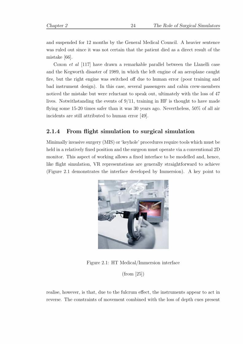
2.1.4 From flight simulation to surgical simulation
Minimally invasive surgery (MIS) or ‘keyhole’ procedures require tools which must be
held in a relatively fixed position and the surgeon must operate via a conventional 2D
monitor. This aspect of working allows a fixed interface to be modelled and, hence,
like flight simulation, VR representations are generally straightforward to achieve
(Figure 2.1 demonstrates the interface developed by Immersion). A key point to
Figure 2.1: HT Medical/Immersion interface
(from [25])
realise, however, is that, due to the fulcrum effect, the instruments appear to act in
reverse. The constraints of movement combined with the loss of depth cues present

Chapter 2 25 The Role of Surgical Simulators
the surgeon with a formidable cognitive task [391].
In the early 1990s, feeling that the advantages of MIS — shorter hospital stays
and less postoperative pain — outweighed concerns about skills in spatial aware-
ness, many surgeons hurriedly invested in new equipment. The numerous tragic
cases which resulted sparked a number of animated debates [221, 224, 269, 372].
One commentator observed that the ‘uncontrolled expansion of surgical endoscopic
practice. . . amounted to the biggest un-audited free-for-all in the history of surgery’
[122]. Simulators were quickly identified as the best solution for this new training
requirement, and were expected to fulfil three separate roles [357, 355]:
• The screening of potential surgical candidates.
• Surgical training and assessment during residency.
• Re-certification of skilled surgeons and ‘skills maintenance’.
Interest in screening candidates led to a number of devices which were essentially
mechanical in nature, and designed purely to test dexterity or visuo-spatial ability,
such as ADEPT (see 2.2). Progress in the development of VR surgical simulators
for MIS procedures has been considerable and is discussed below (Section 2.3).
Although this field has attracted extensive research, the case for introducing
simulators into the training curriculum along the lines of the FAA in North America
(or the Joint Aviation Authority (JAA) in Europe) is far from clear [386]. Until
this area of the training infrastructure can be addressed, however, it is unlikely that
simulators will play a significant role in re-certification; some authors have suggested
that skills maintenance may be more urgently needed [281].
2.2 Assessing skill and ability
2.2.1 Metrics for assessment
2.2.1.1 Metrics workshop
In 2001, a workshop to discuss “Metrics for Objective Assessment of Surgical Skills”
was held in Scottsdale, Arizona. The main goals of the workshop were to ‘define
what is being measured’ and to ‘develop a taxonomy for measurement’. One of the
organisers (Cuschieri) commented that:-

Chapter 2 26 The Role of Surgical Simulators
Surgical competence requires selecting the right people and placing
them in appropriate training/assessment programs. . . Some surgeons will
immediately rise to a level of proficiency, the majority will remain in the
”learning zone” for a longer time until proficiency is obtained, and a few
will never attain a true level of proficiency [123]
A number of devices were introduced to aid in this endeavour, such as the Advanced
Dundee Endoscopic Psychomotor Tester (ADEPT) and the Imperial College As-
sessment Device (ICSAD), described below (2.2.2 and 2.2.3). Opinion at the time
was divided over the usefulness of these tools, but an appropriate model for their
evaluation appears to have been provided by the Objective Structured Assessment
of Technical Skill (OSATS) [335, 266].
2.2.1.2 OSATS
OSATS is a multi-station performance-based assessment of technical skill. The ex-
amination format comprises a specific checklist for each bench model task that is
assessed and a further ‘global’ checklist to afford an overall rating for each student
(see examples in Appendix B). Developed at the University of Toronto, Ontario,
the initial work on OSATS was aimed at: (a) evaluating the reliability of skills as-
sessments; and (b), formulating a methodology to compare live animal platforms to
bench models. Thus the concepts of validity and reliability lie at the heart of OS-
ATS. Five forms of validity were discussed at the Metrics Workshop: face, construct,
content, concurrent and predictive. These terms are defined in Appendix A.1, but
it is convenient to introduce the most commonly used here, since this language is
unavoidable in much of the text which follows. Discussion of the issues surrounding
these concepts and of the relationship between validity and reliability is withheld
until Section 3.3.
2.2.1.3 Construct and Concurrent Validity
Validity refers to the extent to which the test is measuring what one thinks it is
measuring. Several methods have been used to establish the validity of the OSATS.
Firstly, the construct validity was assessed by comparing the scores of candidates
at various levels of training experience (see Figure 2.2). Training level accounts for
40–50% of the variation in checklist and global rating scores, suggesting reasonable
construct validity for both measures. Secondly, to establish the concurrent validity,
an identical set of six stations was administered in both a bench model format and
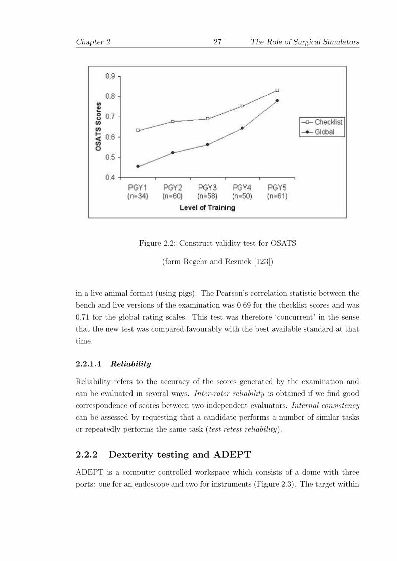
Chapter 2 27 The Role of Surgical Simulators
Figure 2.2: Construct validity test for OSATS
(form Regehr and Reznick [123])
in a live animal format (using pigs). The Pearson’s correlation statistic between the
bench and live versions of the examination was 0.69 for the checklist scores and was
0.71 for the global rating scales. This test was therefore ‘concurrent’ in the sense
that the new test was compared favourably with the best available standard at that
time.
2.2.1.4 Reliability
Reliability refers to the accuracy of the scores generated by the examination and
can be evaluated in several ways. Inter-rater reliability is obtained if we find good
correspondence of scores between two independent evaluators. Internal consistency
can be assessed by requesting that a candidate performs a number of similar tasks
or repeatedly performs the same task (test-retest reliability).
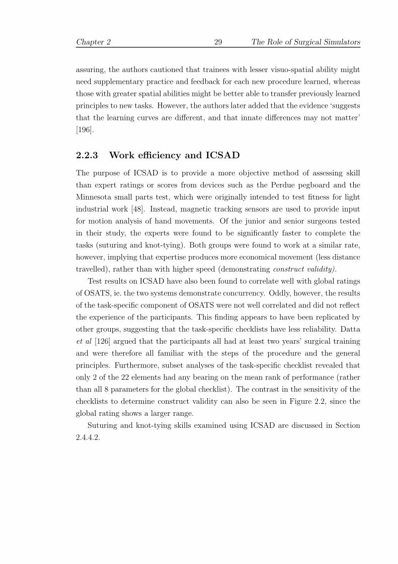
2.2.2 Dexterity testing and ADEPT
ADEPT is a computer controlled workspace which consists of a dome with three
ports: one for an endoscope and two for instruments (Figure 2.3). The target within

Chapter 2 28 The Role of Surgical Simulators
Figure 2.3: ADEPT environment
(from Cuschieri [123])
the dome is at the isocentre and viewed on a standard monitor. It comprises a plate
with four tasks a flick-switch, a joystick, a rotating dial and slider tasks. Contact of
the instruments with the edge of an aperture results in a ‘probe error’. The software
is designed to be self-running, randomly picking tasks and giving instructions.
A good correlation has been demonstrated between performance on ADEPT and
independent clinical assessment of operative skills (ie. concurrent validity) [265]. The
system appears to show a very fast learning curve, after which there is little improve-
ment, suggesting a close correlation with individual ability rather than an acquired
level of skill. Nevertheless, the authors acknowledge that testing of fundamental
abilities remains a subject of much debate.
Dexterity tests have continually failed to show significant differences between
clinicians of non-surgical and surgical specialities [201, 451]. A further problem is
that one’s abilities appear to change. Francis et al [160] observed that the level
of eye-hand coordination of master surgeons on ADEPT was higher than that of
medical students but that their capacity for novel visuo-spatial tasks was lower,
suggesting that age would appear to be an important factor (see also [339, 423]).
Schueneman et al [364] found that gender and left-handedness had a profound effect
on stress levels and achievement in several tests, more so even than age.
In other concurrency tests, training effects appear to be of greater concern.
Wanzel et al [439] examined surgical residents on a series of visuo-spatial skills,
such as the mental rotation of 2D and 3D shapes, and found that those with higher
scores did significantly better in performing a Z-plasty procedure for the first time.
After a brief training and feedback session, however, those with lower scores were
found to be indistinguishable from the highest scoring participants. Although re-
Chapter 2 29 The Role of Surgical Simulators
assuring, the authors cautioned that trainees with lesser visuo-spatial ability might
need supplementary practice and feedback for each new procedure learned, whereas
those with greater spatial abilities might be better able to transfer previously learned
principles to new tasks. However, the authors later added that the evidence ‘suggests
that the learning curves are different, and that innate differences may not matter’
[196].
2.2.3 Work efficiency and ICSAD
The purpose of ICSAD is to provide a more objective method of assessing skill
than expert ratings or scores from devices such as the Perdue pegboard and the
Minnesota small parts test, which were originally intended to test fitness for light
industrial work [48]. Instead, magnetic tracking sensors are used to provide input
for motion analysis of hand movements. Of the junior and senior surgeons tested
in their study, the experts were found to be significantly faster to complete the
tasks (suturing and knot-tying). Both groups were found to work at a similar rate,
however, implying that expertise produces more economical movement (less distance
travelled), rather than with higher speed (demonstrating construct validity).
Test results on ICSAD have also been found to correlate well with global ratings
of OSATS, ie. the two systems demonstrate concurrency. Oddly, however, the results
of the task-specific component of OSATS were not well correlated and did not reflect
the experience of the participants. This finding appears to have been replicated by
other groups, suggesting that the task-specific checklists have less reliability. Datta
et al [126] argued that the participants all had at least two years’ surgical training
and were therefore all familiar with the steps of the procedure and the general
principles. Furthermore, subset analyses of the task-specific checklist revealed that
only 2 of the 22 elements had any bearing on the mean rank of performance (rather
than all 8 parameters for the global checklist). The contrast in the sensitivity of the
checklists to determine construct validity can also be seen in Figure 2.2, since the
global rating shows a larger range.
Suturing and knot-tying skills examined using ICSAD are discussed in Section
2.4.4.2.

Chapter 2 30 The Role of Surgical Simulators
2.3 Simulation of closed procedures
2.3.1 Overview
The drive to develop simulators for MIS procedures has placed this research at the
fore-front of current technology. Over a dozen studies have been undertaken using
the Minimally Invasive Surgical Trainer (MIST-VR) alone. Stone [398] observed
that one reason for the success of MIST was because its development was not driven
by the ‘technology-push’ of the 1990s, which aimed:-
to deliver comprehensive virtual humans using dynamic visual, tac-
tile, auditory and even olfactory modes of interaction. . . The problem
is: who in the real surgical world can afford to procure, operate and
maintain such systems?
A survey of laparoscopic systems is given in Sections 2.3.2 and 2.3.3. Few of these
systems include a haptic component. One exception is described by Cosman et al
[109] who used the device to test a range of metrics (time, economy of movement,
force vectors, and tissue handling) on groups of surgeons, trainees and novices. No
significant differences were found, however, and no further details were given regard-
ing the usefulness of force-feedback. In contrast, endoscopic procedures require some
level of force-feedback, and for this reason, tissue modelling becomes a much more
important requirement. A number of systems are discussed in Section 2.3.4. In open
surgical simulations, haptic feedback is usually considered essential, and examples
are discussed in Section 2.4.
2.3.2 Commercial systems
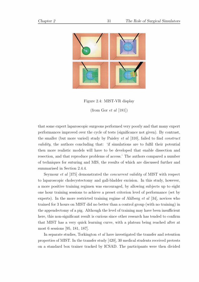
2.3.2.1 MIST-VR
Instead of a complex virtual human, the VR component of MIST comprises a number
of simple objects which have to be manipulated as smoothly as possible (Figure
2.4). The system is therefore highly portable and affordable. Face and construct
validity have been demonstrated by several research groups (see Appendix A.1)
[387, 412]. The study by Gallagher et al [170], however, used a very large sample
population (over 200 subjects), indicating that small differences between the novice
and expert groups may easily have been exaggerated1 [104, 297]. It is also notable
1This kind of analysis has received frequent criticism from opponents of the null hypothesissignificance test, who view inappropriate usage as being ‘bone-headedly misguided’ [296].
Chapter 2 31 The Role of Surgical Simulators
Figure 2.4: MIST-VR display
(from Gor et al [181])
that some expert laparoscopic surgeons performed very poorly and that many expert
performances improved over the cycle of tests (significance not given). By contrast,
the smaller (but more varied) study by Paisley et al [310], failed to find construct
validity, the authors concluding that: ‘if simulations are to fulfil their potential
then more realistic models will have to be developed that enable dissection and
resection, and that reproduce problems of access.’ The authors compared a number
of techniques for suturing and MIS, the results of which are discussed further and
summarised in Section 2.4.4.
Seymour et al [375] demonstrated the concurrent validity of MIST with respect
to laparoscopic cholecystectomy and gall-bladder excision. In this study, however,
a more positive training regimen was encouraged, by allowing subjects up to eight
one hour training sessions to achieve a preset criterion level of performance (set by
experts). In the more restricted training regime of Ahlberg et al [34], novices who
trained for 3 hours on MIST did no better than a control group (with no training) in
the appendectomy of a pig. Although the level of training may have been insufficient
here, this non-significant result is curious since other research has tended to confirm
that MIST has a very quick learning curve, with a plateau being reached after at
most 6 sessions [95, 181, 187].
In separate studies, Torkington et al have investigated the transfer and retention
properties of MIST. In the transfer study [420], 30 medical students received pretests
on a standard box trainer tracked by ICSAD. The participants were then divided
Chapter 2 32 The Role of Surgical Simulators
into 3 groups: (i) control (no training); (ii) MIST-VR, completing 10 repetitions
of all six training tasks twice over a period of 1 hour; and (iii) receiving standard
Basic Skills instruction for 1 hour. The groups were then post-tested on the box
trainer. All groups were observed to improve, though groups (ii) and (iii) improved
significantly more than group (i). Basic instruction was nonetheless found to be
as effective as MIST and although movement efficiency of the dominant hand was
found to improve, this factor with the left hand was found to degrade. Two possible
explanations were offered: firstly, that these results may represent a snapshot of the
learning curve of a non-dominant hand motor skill; and secondly, that the findings
may be related to the different roles performed by the two hands in the task of
grasping and cutting sutures. In either case, the reliability of testing appears to be
partially undermined (see 3.3).
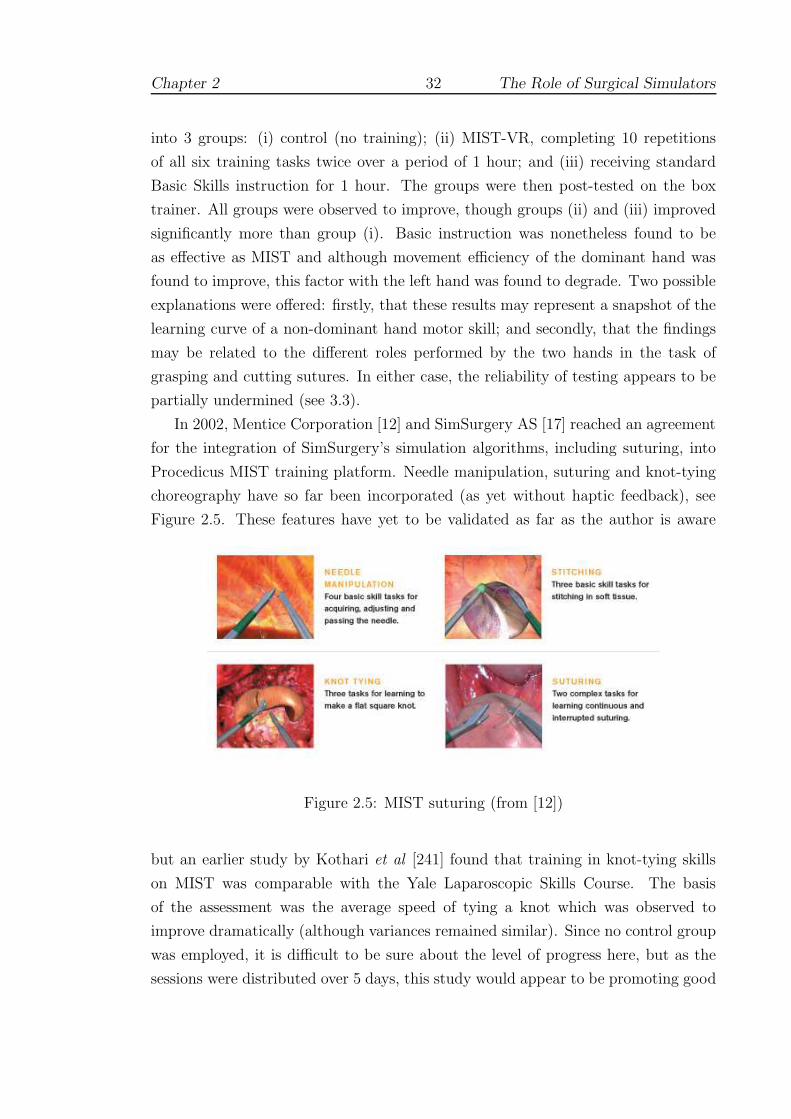
In 2002, Mentice Corporation [12] and SimSurgery AS [17] reached an agreement
for the integration of SimSurgery’s simulation algorithms, including suturing, into
Procedicus MIST training platform. Needle manipulation, suturing and knot-tying
choreography have so far been incorporated (as yet without haptic feedback), see
Figure 2.5. These features have yet to be validated as far as the author is aware
Figure 2.5: MIST suturing (from [12])
but an earlier study by Kothari et al [241] found that training in knot-tying skills
on MIST was comparable with the Yale Laparoscopic Skills Course. The basis
of the assessment was the average speed of tying a knot which was observed to
improve dramatically (although variances remained similar). Since no control group
was employed, it is difficult to be sure about the level of progress here, but as the
sessions were distributed over 5 days, this study would appear to be promoting good

Chapter 2 33 The Role of Surgical Simulators
training practice (see 3.5.8).
2.3.2.2 Wider testing of MIST
To examine retention of skills taught elsewhere, MIST was used to assess 13 trainees
before and after a Basic Skills training course [419]. The results showed that timing
and efficiency metrics improved significantly by the end of course with improvements
being retained at 3 weeks and 3 months as far as the logistics of the participants
would allow. A control group (13 senior medical students with no prior laparoscopic
experience) showed a non-significant trend toward improvement in all parameters.
The accessibility of MIST has allowed researchers to investigate wider problems of
sleep deprivation [411] and the effect of alcohol [237].
In a comparison study of MIST and the ratings of expert observers, Gallagher
and Satava [169] obtained a good level of discrimination between groups of novices,
inexperienced and experienced laparoscopic surgeons for most metrics (overall time,
error and economy of movement — some differences were not apparent, however,
between the inexperienced and experienced groups). The authors also made use of
Cronbach’s alpha (see Section 3.6.2) to give an indication of inter-rater reliability
between the two observers — see Appendix A.1. A Scheffe F-test was adopted to
allow family-wise comparisons (see 7.1.4).
Since operating time has frequently been held to be a distinguishing characteristic
of expert surgeons, Shah et al supposed that reaction time might be a strongly
discriminatory factor [377]. The authors concluded, however, that: ‘using time as a
surrogate measure for operative quality is erroneous.’ An interesting departure from
tests oriented purely towards skills assessment was provided by Pham et al [313]. In
this experiment, all levels of MIST were compared with the Rapid Fire system (using
interfaces from [21] and [25]) which was driven by a specially developed front-end,
known as Smart Tutor. This was designed to adjust the level of feedback as users
became more competent, so that only appropriate feedback was provided. Groups
of medical students were trained using both systems and a pre/post-tested on a
paper-cutting task. Both groups were observed to improve significantly, though the
trainees found the more adaptive ‘smart’ system to be less frustrating2.
2Since there was no control group, the practice effect of the paper-cutting test cannot be ruledout as the cause of the improvement (see 3.6.1).

Chapter 2 34 The Role of Surgical Simulators
2.3.2.3 LapSim
The LapSim laparoscopic trainer (Surgical Science [18]) has tasks that are more real-
istic than those of the MIST, involving structures that are deformable and may bleed
[32]. Haptic feedback has also been added in the latest version, notably with the
Basic Skills 3.0 module, which supports dissection, suturing and knot-tying. These
operations are bimanual and supported by the Surgical Workstation laparoscopic
interface manufactured by Immersion [25]. Figure 2.6 shows the suturing module in
use. It is difficult to be more precise about the extent of this support since this is
Figure 2.6: LapSim Suture module (from [32])
commercially sensitive information and few details have been published. The review
by Schijven et al, however, observes that the system has a high degree of realism
with regard to graphics and tissue instrument interaction but that there are no com-
plete surgical procedures available and that validation of the system is limited but
ongoing [359].
A number of other validation studies may be cited. Duffy et al [140] examined
the performance of 54 surgeons (including attending surgeons and residents of all
levels) over 8 training modules: camera navigation, instrument navigation, coor-
dination, grasping, lifting and grasping, cutting, clip applying, and suturing. A
summary table of significant differences obtained is given in Table 2.1, and shows a
greater level of discrimination as tasks became more complex. The tasks were not
repeated, so there is no assessment of the reliability of these scores (see discussion
in Section 3.6.2). However, post hoc analysis of the most complex (suturing) task
amongst residents revealed an interesting trend of development, the results of which
are reproduced in Figure 2.7. There appears to be little progress until year 5 (al-
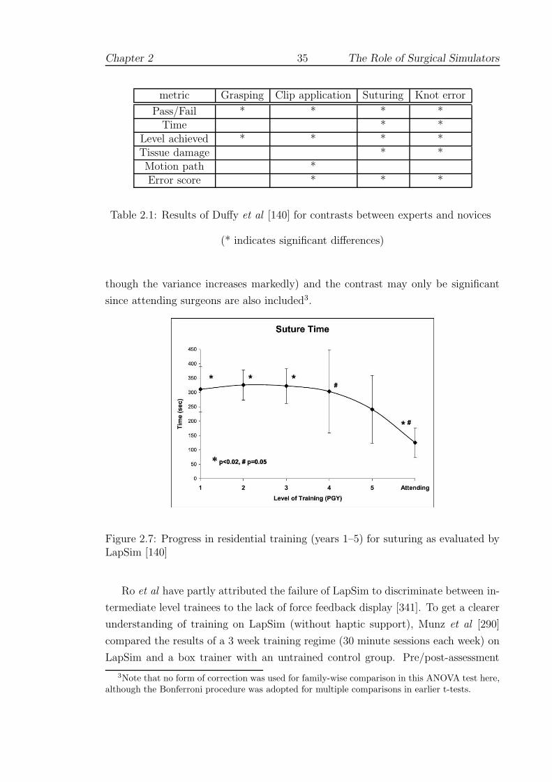
Chapter 2 35 The Role of Surgical Simulators
metric Grasping Clip application Suturing Knot error
Pass/Fail * * * *Time * *
Level achieved * * * *Tissue damage * *Motion path *Error score * * *
Table 2.1: Results of Duffy et al [140] for contrasts between experts and novices
(* indicates significant differences)
though the variance increases markedly) and the contrast may only be significant
since attending surgeons are also included3.
Figure 2.7: Progress in residential training (years 1–5) for suturing as evaluated byLapSim [140]
Ro et al have partly attributed the failure of LapSim to discriminate between in-
termediate level trainees to the lack of force feedback display [341]. To get a clearer
understanding of training on LapSim (without haptic support), Munz et al [290]
compared the results of a 3 week training regime (30 minute sessions each week) on
LapSim and a box trainer with an untrained control group. Pre/post-assessment
3Note that no form of correction was used for family-wise comparison in this ANOVA test here,although the Bonferroni procedure was adopted for multiple comparisons in earlier t-tests.

Chapter 2 36 The Role of Surgical Simulators
tasks were set on the box trainer, using motion analysis and error scores generated
by ICSAD. Compared to the controls, the box trainer group performed significantly
better on most of the parameters, whereas the LapSim group performed signifi-
cantly better on some parameters. There were no significant differences between the
LapSim and box trainer groups. Oddly, time taken was not significantly reduced
suggesting that the performance was still improving, although the authors asserted
(without further evidence) that a plateau in performance was most likely achieved
after 5–6 trials (see Section 3.1.1). It is notable that the number of errors improved
for all groups, including the control. Ultimately, however, the authors concluded
that the study did not demonstrate any significant advantages of one modality over
the other and that the effectiveness of computer-based systems was ‘questionable’.
2.3.2.4 LapMentor and ProMIS
Aggarwal et al observed that LapMentor (Simbionix [16]) allows the trainee to per-
form a complete laparoscopic cholecystectomy and provides a force-feedback display
[32]. The device employs the Xitact LS500 [22] platform for haptic sensation and pro-
vides modules for clipping, dissection and suturing, Figure 2.8. Fully published val-
idation studies have yet to emerge, but Simbionix have published several abstracts.
One study showed that the device received support from a number of trainees and
had been incorporated into the curriculum at Tel Aviv Sourasky Medical Center in
Israel (Szold et al [410]). Another compared two groups, one with 8 hours’ training
on the simulator and the other using normal teaching methods (observation and
a box trainer). Preliminary results (unspecified) were found indicate significantly
superior technical skill acquisition for the group trained on the simulator [393].
In the ProMIS environment (Haptica Inc. [8]), users interact with virtual and
physical models in the same unit and the system provides facilities for instrument
handling, dissection, suturing and intra-corporeal knot-tying, diathermy and ultra-
sonics. Trainees are tracked and provided with feedback as numeric data (time,
path, ‘smoothness’ of movement) and graphical/video playback. The technology
underpinning the device is a fusion of camera-based tracking systems, video analysis
and VR. Several pilot evaluation studies have been completed:
• van Sickle et al demonstrated construct validity between experts and novices
[432].
• Broe et al [76] were able to discriminate between experienced and inexperi-
enced residents for the dissection and targeting tasks and found good inter-

Chapter 2 37 The Role of Surgical Simulators
Figure 2.8: LapMentor dissection and suturing (from [16] and [32])
Chapter 2 38 The Role of Surgical Simulators
rater correlation (using Cronbach’s alpha) between blinded expert reviewers
of the video playback. The authors observed that the failure of the orientation
task to discriminate between groups suggested that the system required mod-
ification before it could be used in isolation as an assessment tool. It should
be noted that this inference is not correct (see 3.3.2 and 3.6.2)
• Hance et al tested 32 subjects, comprising novices, trainees and experts, in
object positioning and dissection tasks and found that significant differences
existed between experts and novices, but not between experts and trainees
[197].
• McCluskey et al undertook a study comprising 11 subjects examined over 3
trials of a suturing task on ProMIS [272]. Time, tool path and smoothness
were strongly correlated, as were accuracy of suture placement and error scores
(assessed by observers). Testing these correlations further, the authors found
that: (i) smoothness of movement significantly correlated with accuracy in 2
trials; and (ii) time correlated well with error scores in 2 trials.
2.3.3 Inanimate trainers for laparoscopy
Testing on inanimate or box (ie. non-VR) trainers has tended to reinforce the im-
portance of levels of experience and recent practice [133]. In fact, junior surgeons
with recent practice in laparoscopy were able to out-perform their seniors who had
greater experience of open surgery, but who had not practiced laparoscopic tech-
niques for several years [157]. Regular training was found to have a dramatic effect
in the study by Traxer et al [421]. In the control group, the time to complete a
porcine nephrectomy decreased from 365 to 301 seconds on average, demonstrating
a significant practice effect (from testing). In the trained group, practice for 30
minutes daily for 10 days produced a shift from 341 to 176 seconds (both practice
effect and experimental effect). Operative assessment also improved (regardless of
grouping), so that it appears that the main impact of the simulator was to improve
the efficiency of working.
By evaluating hundreds of participants in Basic Skills courses with a non-VR
trainer, Rosser et al [347, 348] were able to conclude that: ‘skills relevant to laparo-
scopic performance can be acquired with a high level of competence in a brief course
unrelated to prior surgical experience, sex, or age.’ As previously, the large number
of participants is a potential concern here (see above). Nevertheless, Scott et al
[369] have produced evidence which broadly supports this conclusion using a regular

Chapter 2 39 The Role of Surgical Simulators
training regime (30 minutes daily for 10 days) on a Stortz video-trainer. The rate
of learning for second year medical students was found to be significantly greater
than that of second and third year residents. (This finding may have reflected the
lighter workload of medical students who may also have been more motivated by
their voluntary participation.) Furthermore, in a remarkable series of studies with
the same device, the authors [366, 367, 368] showed that residents’ performance on
human patients also improved (as assessed by supervising surgeons).
2.3.4 Endoscopy and arthroscopy
2.3.4.1 Approaches
Research with the angled laparoscope has shown that the learning rate is associated
with visuo-spatial ability [?], but the ultimate problem of assessing a simulator by
outcomes on patients may not be possible [170]. Demonstrating construct validity
often seems to be given as the best possible alternative. An interesting example of
the limitations of this form of testing, however, was observed with the Sheffield Knee
Arthroscopy Trainer (SKAT). Construct validity was established for most tasks on
SKAT, but where feedback was inappropriate — no forces were given in response to
collisions — experts appeared to have no advantage [39]. Moody and Waterworth
have nevertheless implemented a user-centred training tutorial, WISHKATS, based
on this device [283].
Endoscopic simulators (like SKAT) have yet to be widely tested, since the mod-
elling requirement is more demanding and has tended to dominate research [240, 242,
440], see 4 (and 3.4.3 for work on the Procedicus simulators). There are notable ex-
ceptions: controlled studies of students with the Simbionix Uromentor [443, 449]
have shown significant learning effects in the trained group with respect to the con-
trol group, indicating that the required skills can be rapidly acquired by novices.
A particular difficulty with training on urinary endoscopic procedures is that they
are often ‘one man’ devices in which the teacher cannot assist the trainee directly.
Brehmer and Tolley [69] compared training using a commercial bench model (from
Mediskills) to checklist-scored performance with human patients. Of the 14 partic-
ipants (5 trainees and 9 consultants), all found the simulator realistic to use and
there was no significant discrimination between performance on the simulator and
human patients. Those consultants and trainees with specific practice in advanced
endourology, however, gained significantly higher scores in both tests.
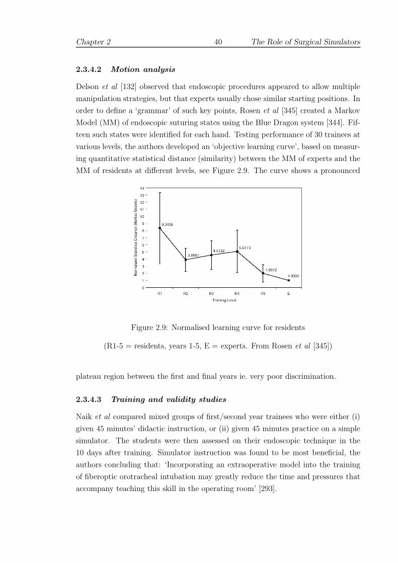
Chapter 2 40 The Role of Surgical Simulators
2.3.4.2 Motion analysis
Delson et al [132] observed that endoscopic procedures appeared to allow multiple
manipulation strategies, but that experts usually chose similar starting positions. In
order to define a ‘grammar’ of such key points, Rosen et al [345] created a Markov
Model (MM) of endoscopic suturing states using the Blue Dragon system [344]. Fif-
teen such states were identified for each hand. Testing performance of 30 trainees at
various levels, the authors developed an ‘objective learning curve’, based on measur-
ing quantitative statistical distance (similarity) between the MM of experts and the
MM of residents at different levels, see Figure 2.9. The curve shows a pronounced
Figure 2.9: Normalised learning curve for residents
(R1-5 = residents, years 1-5, E = experts. From Rosen et al [345])
plateau region between the first and final years ie. very poor discrimination.
2.3.4.3 Training and validity studies
Naik et al compared mixed groups of first/second year trainees who were either (i)
given 45 minutes’ didactic instruction, or (ii) given 45 minutes practice on a simple
simulator. The students were then assessed on their endoscopic technique in the
10 days after training. Simulator instruction was found to be most beneficial, the
authors concluding that: ‘Incorporating an extraoperative model into the training
of fiberoptic orotracheal intubation may greatly reduce the time and pressures that
accompany teaching this skill in the operating room’ [293].

Chapter 2 41 The Role of Surgical Simulators
Ritter et al [340] observed that there is a consensus that 100–400 procedures are
required to achieve competency in endoscopic procedures (see Section 3.1). Noting
the earlier study by Ferlitsch et al [154], which demonstrated construct validity
between novices and experts of more than 1000 procedures, the authors wished
to test more closely matched groups. Novices (<10 procedures performed) were
therefore contrasted with a group of ‘intermediate’ experience (100–250 procedures
performed) over 3 trials using the GI Mentor II device (Simbionix [16]). An abstract
VR task was selected to focus the test upon psychomotor (rather than cognitive)
skills. The task, which required trainees to pop virtual balloons, was assessed by the
number of balloons popped, time and collision errors (between the virtual needle and
the sides of the vessel). The number of balloons popped was significantly different
on all three trials, though time taken was only significantly different on the first trial
and collision errors on the first and third.
The authors argued that these differences were sufficiently consistent to validate
the device and pointed out that post hoc analysis (ANOVA with Dunn correction
for multiple comparisons) showed significant improvement for the novices, but not
for the intermediate group. Analysis also showed a good correlation between the
first and second trials, indicating some degree of inter-trial reliability. The premise
(validity) of this experiment is not in dispute, but there would seem to be a number
of reliability issues. For example, time differences were significant on only the first
trial, but this was said to demonstrate that the intermediate group was “consistently
faster.” Similarly, the poorer level of correlation between the second and third trials
does support the authors’ claim for consistency, especially for such a small number
of trials. These issues are explored further in Section 3.3 (and throughout this
document).
Moorthy et al have investigated the validity and reliability of both the GI Mentor
system (Simbionix, as above) [285] and the AccuTouch Endoscopy Simulator (from
Immersion Medical [10]) [286]. In the former study, the 32 participants (novices,
intermediate level and experienced endoscopists) were requested to undertake two
cases on the simulator, with each module being repeated twice. Metrics of perfor-
mance comprised time, efficiency and several observational parameters eg. percent-
age of pathology seen. Also, two blinded observers rated performance after watching
video playback provided by the simulator. Significant differences were seen for all
metrics between the novice and experienced groups, although differences were often
blurred with respect to the intermediate group. Nevertheless, the data suggested
good inter-rater and inter-trial reliability, with some evidence for learning between

Chapter 2 42 The Role of Surgical Simulators
the first and fourth trials. A questionnaire to assess the usability of the system found
that endoscopists scored the simulator high on its graphics, complexity, and poten-
tial as a training tool, but that 70% of the responders rated esophageal intubation
as unrealistically easy.
For the AccuTouch study, an endoscopy suite was developed along with an
OSATS-style global scoring sheet (denoted as ICASE). 20 people (six experts, seven
intermediate level subjects and seven novices) participated in the one test case of
the suite which was recorded by ceiling-mounted cameras for external assessment
(by blinded observers using ICASE). There were no significant differences across the
groups in terms of the time taken for the procedure or for depth of insertion. There
was, however, a significant difference across the range in terms of the percentage
of time spent in ‘red-out’, ie. without vision, indicating that the experts were far
more dexterous in their control of the device. Also, the ICASE score showed good
discrimination of the three groups and good inter-rater reliability, although these
scores were only well-correlated with the ‘red-out’ metric. One problem of studies
of this kind was that the demand placed upon external observers was consider-
able: it was estimated that each observer spent approximately 5 hours evaluating
all the simulations, which might have to be trebled with more complex procedures
(eg. colonoscopy).
2.3.5 Interventional procedures
2.3.5.1 Approaches
A web-based catheterisation simulation has been developed by El Khalili [75, 144]
which used the mouse pointer for interaction. Although it was not possible to give
haptic feedback, forces were represented by a display widget. Perhaps finding such
interfaces too restricting, Chong et al opted to create a silicone rubber phantom
using a spiral Computed Tomography (CT) scan of an aortic aneurysm [99, 100].
The aortic model was attached to a pump to allow coloured dye to circulate for
the simulation of arteriography and the illusion of an X-ray image was produced
by placing a real X-ray on top of the apparatus. This system does not seem to
have been tested or developed further: in vitro systems have high initial costs and
limited lifetimes since they cannot be altered later to allow different anatomy or
patient-specific rehearsal [184].
Nevertheless, several commercial systems have been developed and various de-
formable modelling methodologies have been advanced (eg. [59, 178, 330, 466]). The

Chapter 2 43 The Role of Surgical Simulators
Vascular Interventional Surgical Trainer (VIST; from Mentice [12]), for example,
provides a complete cardiovascular system with a haptic interface, an instructional
system (first monitor) and a synthetic x-ray system (second monitor), Figure 2.10.
Figure 2.10: VIST simulator (Mentice [12])
VIST is capable of simulating haemodynamics, dye contrast media mixing and in-
teraction of the catheter. Coronary stenting can also be practiced as well as placing
leads for pacing. Although promising, few of these systems have been validated
to acceptable psychometric and scientific standards [93, 168, 452]. A number of
completed studies are reviewed below.
2.3.5.2 Training and validity studies
Prystowsky et al [321] have tested a prototype VR device developed by jointly
Musculo-Graphics Inc. and Boston Dynamics Inc. This system allowed stereo graph-
ics and haptic feedback via a PHANToM Desktop device. In the study, 37 first-year
medical students, 14 third year medical students and 9 surgical residents partici-
pated. In the pre-test and post-test, each participant attempted to perform 2 in-
travenous (IV) insertions on other subjects within the experiment. The treatment
phase comprised orientation and ‘training’ for 12 minutes in the VR module and
ratings were compiled by experts on a four-point Likert scale.
In the pre-test, there were significant differences among the groups with respect to
IV insertions but none were seen amongst the groups as assessed by VR module. The
rate of improvement was also similar for each group, indicating that the participants

Chapter 2 44 The Role of Surgical Simulators
had equal difficulty becoming accustomed to the VR environment. Despite achieving
a VR success rate of approximately 50% in their last 4 minutes of VR use, the first-
year students’ post-test success rate returned to 24%, which was similar to their
pre-test success rate. The authors concluded that most groups were still in the
process of learning the VR task at the end of the training period. Intriguingly they
did not feel that IV insertions on other members of the group might have been
detrimental to the study.
Given the poor findings of this study, Reznek et al [334] used a more open study
design, involving usability and validity, to test CathSim ([24]). From a literature
search, it was estimated that the learning curve would level at around 10 proce-
dures, allowing subjects to be allocated as: (i) novices, with no prior experience;
(ii) residents (up to 10 procedures); and (iii) attending physicians (more than 10
procedures). The results of a test comprising 5 attempted IV insertions were found
to support construct validity for 5 of the 9 parameters obtained from the system,
at least between the expert and novice groups. Of the failing parameters, one (fre-
quency of success) appeared to be due to poor instruction of the participants and
two more (frequency of hematoma and number of recannulations) were generally
related to experience, though non-significant. It is notable that the intermediate
level group was often indistinguishable from the experts (except for average time for
tourniquet application) and, on some parameters, performance was markedly worse
than both the other groups (eg. total number of needle recannulations and number
of incorrect tools selected ; significance not given). From questionnaires, it was felt
that the realism of haptic feedback was above the average expected, but respondents
also felt that the system was quite difficult to learn.
2.3.6 Robotic assistance and augmented reality
Several systems have been developed to provide robotic assistance in MIS proce-
dures, notably daVinci and Zeus. Prasad et al [320] have shown that compared
with performance on a standard laparoscopic trainer, robotic assistance allows for in-
creasing speed and consistency while maintaining precision over multiple repetitions.
The learning curve for using daVinci, which allows a magnified three-dimensional
videoscopic view of the operative field, has been examined by [199]. Verner et al
[433] used daVinci to track the ‘flight path’ of various simulator drills with distinc-
tion between experts and novices. Their intention, however, is to create reference
criteria for an ideal path, against which all trainees might be measured.

Chapter 2 45 The Role of Surgical Simulators
An interesting departure from devices which are intended purely for training and
assessment is the possibility of providing assistance during procedures by overlaying
information about the patient on the surgeon’s visual field [29]. The application
areas for this technology include biopsy [165] and laparoscopic surgery [392]. Few
studies have been completed to show the viability of this technology, although King
et al were able to claim a 1mm focal plane accuracy for their stereo augmented
microscope [234].
2.4 Simulation of open surgery
2.4.1 Overview
The difficulty of producing satisfactory VR representations of anatomy and tool/hand
interaction in open surgical contexts has forced researchers to adopt a ‘part-task’
approach, rather than the virtual human systems predicted by [205, 124] and oth-
ers (cf 2.3). Instead, prototype simulators have been developed in many different
areas: dentistry [417], anaesthesia [292, 446], facial reconstruction [229, 230], eye
[349, 351, 360] and heart [294] surgery; and for various techniques, eg. bone-dissection
[33], suturing [58, 79, 209, 444] and knot-tying [314]. The validity of the part-task
approach is discussed in Section 3.5.11.
In terms of completed studies, however, the literature is not vast, the bulk of
research being concentrated upon deformation modelling and the physical interface,
ie. software and hardware. The importance of haptic feedback for surgeons has been
stressed by many authors (eg. [82]), but the problem of finding appropriate physical
interfaces (which may not exist) and the solutions imposed will form a recurrent
theme throughout the remainder of this thesis. This section focuses upon the re-
sults of various prototypes and trials: tissue modelling requirements and potential
solutions are discussed in Chapter 4.
2.4.2 Tissue manipulation
2.4.2.1 Background
VR researchers face considerable difficulties in trying to provide convincing repre-
sentations of tissue manipulation, since forces may be acting simultaneously from
different points of origin. An early system of this type, developed by d’Aulignac et
al [127], was intended to train the recognition of thromboses at depth within tissue.
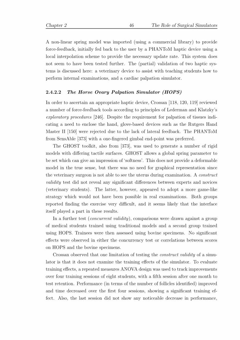
Chapter 2 46 The Role of Surgical Simulators
A non-linear spring model was imported (using a commercial library) to provide
force-feedback, initially fed back to the user by a PHANToM haptic device using a
local interpolation scheme to provide the necessary update rate. This system does
not seem to have been tested further. The (partial) validation of two haptic sys-
tems is discussed here: a veterinary device to assist with teaching students how to
perform internal examinations, and a cardiac palpation simulator.
2.4.2.2 The Horse Ovary Palpation Simulator (HOPS)
In order to ascertain an appropriate haptic device, Crossan [118, 120, 119] reviewed
a number of force-feedback tools according to principles of Lederman and Klatzky’s
exploratory procedures [246]. Despite the requirement for palpation of tissues indi-
cating a need to enclose the hand, glove-based devices such as the Rutgers Hand
Master II [150] were rejected due to the lack of lateral feedback. The PHANToM
from SensAble [373] with a one-fingered gimbal end-point was preferred.
The GHOST toolkit, also from [373], was used to generate a number of rigid
models with differing tactile surfaces. GHOST allows a global spring parameter to
be set which can give an impression of ‘softness’. This does not provide a deformable
model in the true sense, but there was no need for graphical representation since
the veterinary surgeon is not able to see the uterus during examination. A construct
validity test did not reveal any significant differences between experts and novices
(veterinary students). The latter, however, appeared to adopt a more game-like
strategy which would not have been possible in real examinations. Both groups
reported finding the exercise very difficult, and it seems likely that the interface
itself played a part in these results.
In a further test (concurrent validity), comparisons were drawn against a group
of medical students trained using traditional models and a second group trained
using HOPS. Trainees were then assessed using bovine specimens. No significant
effects were observed in either the concurrency test or correlations between scores
on HOPS and the bovine specimens.
Crossan observed that one limitation of testing the construct validity of a simu-
lator is that it does not examine the training effects of the simulator. To evaluate
training effects, a repeated measures ANOVA design was used to track improvements
over four training sessions of eight students, with a fifth session after one month to
test retention. Performance (in terms of the number of follicles identified) improved
and time decreased over the first four sessions, showing a significant training ef-
fect. Also, the last session did not show any noticeable decrease in performance,
Chapter 2 47 The Role of Surgical Simulators
indicating the retention of skills acquired.
In conclusion, Crossan observed that a significant omission from HOPS was the
ability to hold the tissue, as say, between the thumb and forefinger. A pilot study
using two PHANToMs had failed, however, in that it had not proved possible to
calibrate the instruments sufficiently well to use them together. It is equally likely,
in the present author’s opinion, that the lack of an appropriate deformable model
would have contributed towards this problem.
2.4.2.3 Cardiac Surgery
Inanimate trainers have been used successfully within cardiothoracic training for
many years, with an entire curriculum being built around some devices [182]. To
simulate surgery, however, a greater level of interaction is required. Nakao [294]
employed several sophisticated soft tissue models to develop a cardiac palpation sim-
ulator, with the objective of teaching trainees how to assess sclerotic tissue during
open surgery. Several models were required to support different steps in the proce-
dure. A particle-based model was employed to represent the chest wall to support
cutting, using a minimal tetrahedral subdivision algorithm. Using this topological
configuration, a finite element model (FEM) was computed (on-line) to allow more
accurate modelling of the opening of the chest cavity. The heart itself comprised
two models: the first using a FEM to allow modelling of normal/sclerotic tissue; and
the second, based on the ‘Long Element Method’ of [110] to provide a ‘heartbeat’.
The haptic representation of grasping or rather, pinching, the tissue was provided
by linking two PHANToMs together as Figure 2.11.
Evaluation of the model was provided by 8 cardiac surgeons who provided a
subjective assessment of the model for normal and sclerotic tissue. Normal stiffness
(Young’s Modulus) was rated at between of 1.0–1.2 MPa, sclerotic models between
2.8–3.4 MPa. A later test assessed the ability of 18 medical students trained either
with: (i) no training (control); (ii) verbal information from surgeons expressing
stiffness of normal aortas using rubber hose; or (iii) with the cardiac simulator (1.0
MPa model). The results were not supported statistically, but at least graphically,
appeared to favour the simulator.
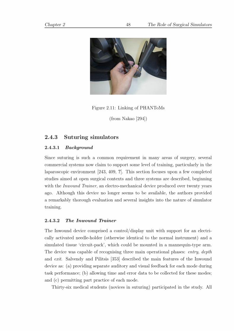
Chapter 2 48 The Role of Surgical Simulators
Figure 2.11: Linking of PHANToMs
(from Nakao [294])
2.4.3 Suturing simulators
2.4.3.1 Background
Since suturing is such a common requirement in many areas of surgery, several
commercial systems now claim to support some level of training, particularly in the
laparoscopic environment [243, 409, ?]. This section focuses upon a few completed
studies aimed at open surgical contexts and three systems are described, beginning
with the Inwound Trainer, an electro-mechanical device produced over twenty years
ago. Although this device no longer seems to be available, the authors provided
a remarkably thorough evaluation and several insights into the nature of simulator
training.
2.4.3.2 The Inwound Trainer
The Inwound device comprised a control/display unit with support for an electri-
cally activated needle-holder (otherwise identical to the normal instrument) and a
simulated tissue ‘circuit-pack’, which could be mounted in a mannequin-type arm.
The device was capable of recognising three main operational phases: entry, depth
and exit. Salvendy and Pilitsis [353] described the main features of the Inwound
device as: (a) providing separate auditory and visual feedback for each mode during
task performance; (b) allowing time and error data to be collected for these modes;
and (c) permitting part practice of each mode.
Thirty-six medical students (novices in suturing) participated in the study. All
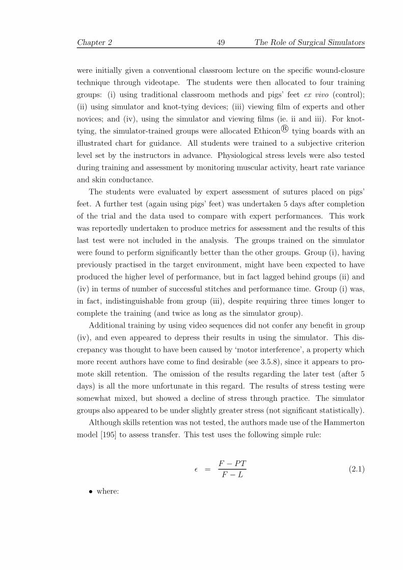
Chapter 2 49 The Role of Surgical Simulators
were initially given a conventional classroom lecture on the specific wound-closure
technique through videotape. The students were then allocated to four training
groups: (i) using traditional classroom methods and pigs’ feet ex vivo (control);
(ii) using simulator and knot-tying devices; (iii) viewing film of experts and other
novices; and (iv), using the simulator and viewing films (ie. ii and iii). For knot-
tying, the simulator-trained groups were allocated Ethicon r© tying boards with an
illustrated chart for guidance. All students were trained to a subjective criterion
level set by the instructors in advance. Physiological stress levels were also tested
during training and assessment by monitoring muscular activity, heart rate variance
and skin conductance.
The students were evaluated by expert assessment of sutures placed on pigs’
feet. A further test (again using pigs’ feet) was undertaken 5 days after completion
of the trial and the data used to compare with expert performances. This work
was reportedly undertaken to produce metrics for assessment and the results of this
last test were not included in the analysis. The groups trained on the simulator
were found to perform significantly better than the other groups. Group (i), having
previously practised in the target environment, might have been expected to have
produced the higher level of performance, but in fact lagged behind groups (ii) and
(iv) in terms of number of successful stitches and performance time. Group (i) was,
in fact, indistinguishable from group (iii), despite requiring three times longer to
complete the training (and twice as long as the simulator group).
Additional training by using video sequences did not confer any benefit in group
(iv), and even appeared to depress their results in using the simulator. This dis-
crepancy was thought to have been caused by ‘motor interference’, a property which
more recent authors have come to find desirable (see 3.5.8), since it appears to pro-
mote skill retention. The omission of the results regarding the later test (after 5
days) is all the more unfortunate in this regard. The results of stress testing were
somewhat mixed, but showed a decline of stress through practice. The simulator
groups also appeared to be under slightly greater stress (not significant statistically).
Although skills retention was not tested, the authors made use of the Hammerton
model [195] to assess transfer. This test uses the following simple rule:
ε =F − PT
F − L(2.1)
• where:

Chapter 2 50 The Role of Surgical Simulators
F = mean performance time on simulator first trial
L = mean performance time on simulator last trial
PT = mean performance time on first post-transfer trial
and transfer is zero if ε = 0 and positive if ε > 0.
The values reported for the simulator groups were ε = 1.34 for group (ii) and
ε = 0.73 for group (iv). The authors concluded that these results ‘should encourage
the use of this device as an inexpensive and effective training instrument.’ It is not
clear whether any other institutions followed this recommendation, but the author
is not aware of any further studies using a similar device.
2.4.3.3 The Boston Dynamics Incorporated (BDI) Simulator
The BDI simulator provided two PHANToM devices for bimanual interaction and
allowed a standing pose by projecting the scene onto a semi-reflective mirror, see
Figure 2.12. The underlying physical model is described in Section 4.7.2, but for
Figure 2.12: BDI Simulator
(from [52], web page and simulator now withdrawn)
testing purposes it should be noted that the user was placed in open access position,
only one hand being tested at any one time. It does not appear that there was any
mechanism to release and re-grab the needle (‘the user sutures the tubes together
by puncturing each tube in sequence, then pulling the suture material tight’) [318].
In [307, 308], O’Toole et al proposed a number of candidate metrics for assessing
vascular surgical technique. To test the (construct) validity of the metrics, an ex-
periment was devised using 12 medical students and 8 experienced surgeons, under

Chapter 2 51 The Role of Surgical Simulators
three conditions: (i) using the dominant hand; (ii) using the non-dominant hand;
and (iii), using the dominant hand, but guided by a 3D vector which was displayed
graphically. Each trial comprised four stitches and was performed in the order pre-
sented in Table 2.2. All trials were performed in one session.
Trial Test condition
0-5 Dominant hand6-7 Non-dominant hand8-11 Guided by 3D vector12-14 Dominant hand
Table 2.2: BDI study protocol
Given the seminal importance of this research towards the present study, the
metrics and the results of the validity test are summarised in Table 2.3. The results
show that three metrics were statistically valid discriminators between experts and
trainees for both hands: time, tool motion and tissue damage. Since, time and
tool motion have been described as providing good discrimination elsewhere (eg. for
ICSAD, see 2.2.3), this result is consistent with other findings.
The significance of the ‘damage’ metrics is less clear, since — as the authors
admitted — the name was misleading. Whereas peak force and surface damage were
associated with the reaction of the model at initial contact (ie. prior to insertion),
tissue damage was intended to assess force (above a critical threshold) away from
the tangent of the needle thereafter. This was calculated by the summation of force
samples, suggesting a property more closely related to impulse (ie. force × time)
than distress. In general, neither peak force nor surface damage were significantly
different between the groups, but the student group took significantly longer to
perform each ‘suture’. It may be, therefore, that tissue damage was more closely
related to time than force.
The 3D vector guide condition gave the user real-time feedback relating to the
angle between the surface normal and tangent to the needle at the point of contact.
The students seemed to be able to exploit this novel feature more successfully than
the surgeons, since their performance with respect to the angular error metric was
superior during these trials. Nevertheless, this ‘improvement’ seems to have been at
the expense of a decrease in performance with respect to both ‘damage’ parameters
( the surface damage metric was significantly different between the groups under
this condition). Although the surgeons’ group did not seem to be able to adapt

Chapter 2 52 The Role of Surgical Simulators
Metric Description Constructvalidity(1)
Learning(2)
Guided(3)
Time (s) Total time from the first contactof the vessel until the last stitchis completed
DH, NDH E, T E
Accuracy(m)
Distance from displayed targetmarker
E, T
Peak force(N)
Largest force applied to the tissuemodel. A minimum as requiredto puncture the vessel. Increaseswith angular error
T
Tissuedamage(N/stitch)
Sum of force applied to the tis-sue in excess of a threshold (theminimum puncture force) accruedafter puncturing. Increases withforce components which deviatefrom the tangent of the needle
DH, NDH E, T E
Surfacedamage(N/stitch)
Sum of force applied to the sur-face of the tissue in excess of athreshold, (heavily) weighted bydamage for scratches
T E
Angularerror(degrees)
The average angular differencebetween the needle tangent vec-tor and the tissue’s normal vectorat the point of tissue contact.
T
Overallscore
A weighted average of factors 1-6,normalised to 50-100%
DH E, T E
Tool mo-tion (m)
Total distance that the tool tiptravels. No feedback was given forthis metric, and hence it was ex-cluded from the overall score
DH, NDH E E
Table 2.3: BDI simulator results
(synthesised from [308])
(1) DH, NDH indicate that construct validity was significant for thedominant and/or non-dominant hand, respectively.
(2) E, T indicate significant improvements in the expert and traineegroups respectively. Improvements in learning were assessed using aver-aged data from trials 0/1 compared with trials 13/14.
(3) Under the 3D vector guided condition E or T indicates that thisgroup performed statistically better (ie. obtained a lower error score)than the other.

Chapter 2 53 The Role of Surgical Simulators
their technique, their scores for tissue damage would also seem to have deteriorated
(significance not tested). Interestingly, these effects were not visible in earlier or
later trials, indicating that these changes in behaviour were not retained (see 3.5.8).
The first and last pair of trials (dominant-handed) were used to assess possi-
ble learning effects on each metric. Both groups showed significant improvement
on many of the parameters (see Table 2.3). ANOVA models of group, trial and
group×trial effect also showed that student and surgeon performances changed sig-
nificantly over time, although the relative level of improvement was not statistically
significant between the groups. The learning curve for dominant-handed trials on
the tissue damage metric is reproduced in Figure 2.13(a) (plotted values are mean
±1 standard error). It is notable that both groups appear to be reaching plateaux
after 3 or 4 trials. Also, although both groups appear to be converging very quickly,
the variance of the student group is still visibly larger.
Reznick [336] (see 2.2.1) provided an editorial on the results of these tests, not-
ing that although the technology was moving forwards quickly, there were several
possible criticisms. In particular, it was pointed out that:
1. Reliability and concurrent validity were not assessed.
2. The two groups were disparate in terms of their surgical experience and simple
misconceptions (on the behalf of students) may explain the observed results.
3. The improvement of scores was perhaps more a matter of becoming used to
the simulator than a matter of developing specific surgical skills.
4. Suturing was performed with a needle driver but without the aid of forceps.
Many suturing tasks rely on the coordinated relationship between the move-
ment of two hands.
5. The apparent departures from the surgical reality beg the question as to
whether skills acquired in a virtual environment will be transferable to the
real world of human operations.
These issues will certainly need to be addressed if more successful simulations are to
be built (the development of the BDI simulator has now been suspended [R. Playter,
personal communication, July 2004 ]). It is argued, however, that the focus on skills
assessment in isolation from other factors, in both the study and the critique, is too
narrow: the data would appear to have more in common with the learning curves
of Starkes and others (see 3.1), than with definitive metrics of skill or ability.
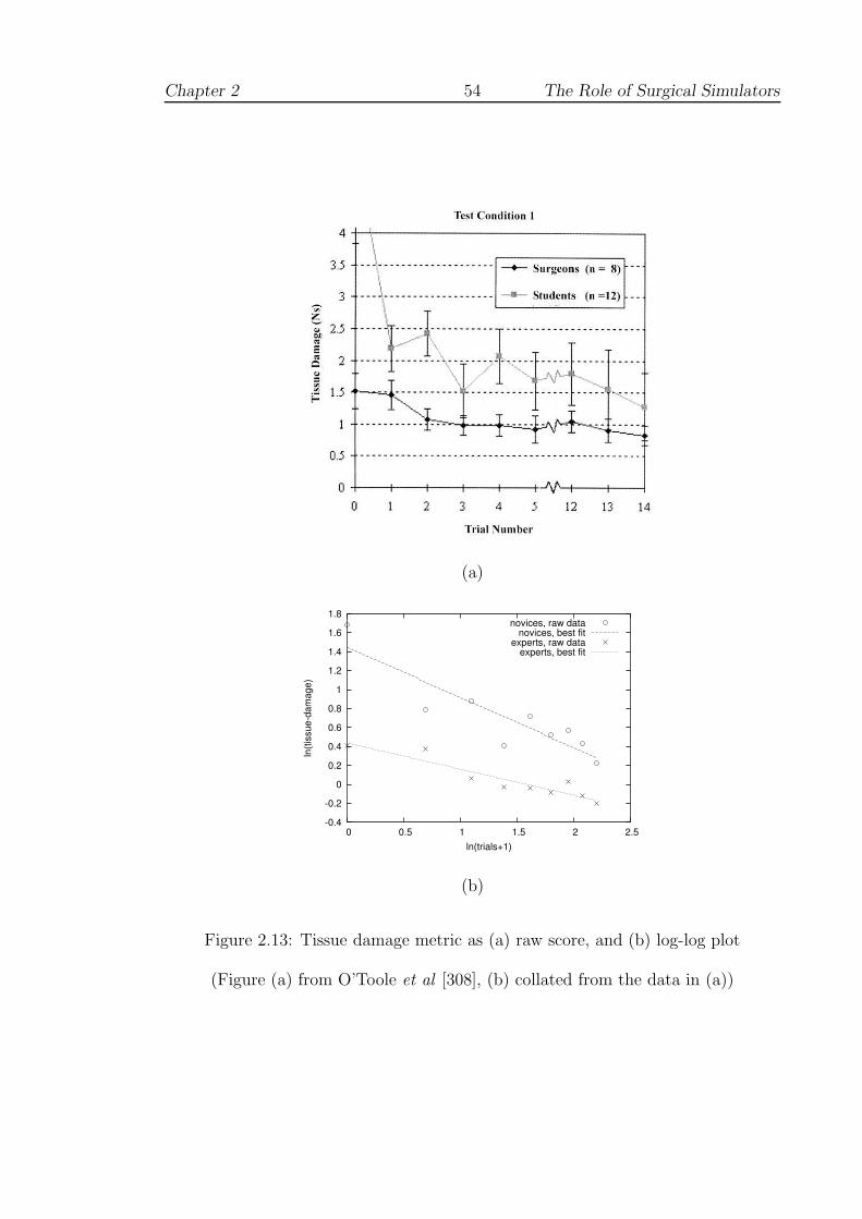
Chapter 2 54 The Role of Surgical Simulators
(a)
-0.4
-0.2
0
0.2
0.4
0.6
0.8
1
1.2
1.4
1.6
1.8
0 0.5 1 1.5 2 2.5
ln(ti
ssue
-dam
age)
ln(trials+1)
novices, raw datanovices, best fit
experts, raw dataexperts, best fit
(b)
Figure 2.13: Tissue damage metric as (a) raw score, and (b) log-log plot
(Figure (a) from O’Toole et al [308], (b) collated from the data in (a))
Chapter 2 55 The Role of Surgical Simulators
The apparent improvement in performance over the session seems to have moti-
vated the follow up study by Murray et al [291] which examined the learning curve
using the BDI simulator (only an abstract summary was published). Five novices
completed multiple passes of a virtual needle through a target overlying a ‘vessel’
in daily sessions of twenty minutes. This was repeated for 13–17 days over a 24 day
period. Increased performance on the simulator was observed on a 6 metric scale
(comprising: time to complete task, accuracy, peak force applied, tissue damage and
angle error) from 25.2± 18.5 (mean ± standard deviation) to 73.4 ±7.1, reaching
a plateau between 7 and 11 sessions. It is difficult to comment further since these
data do not appear to be comparable with the earlier work and no curves or raw
data were published. The subject of learning curves, however, is explored further in
Section 3.5.1.
2.4.3.4 Strain gauge assessment/VR simulator
Moody et al [282] presented results of two sets of construct validity analyses: the
first, using strain gauges attached to real instruments, and the second, using the
down-loadable VR suturing simulation developed by Jeff Berkley [58] at the Human
Interface Technology Laboratory at the University of Washington, see 4.3 below.
• Strain gauge analysis
In the first study, strain gauges were connected to surgical needle-holders and
forceps to examine contact forces during the insertion of ‘purse string’ sutures
into a bench model (porcine aorta). Participants in the study comprised 2
senior registrars, 2 junior registrars and 2 nurses (novices). Given the small
number of subjects, no statistical analyses were undertaken. Results were,
however, compared with subjective metrics proposed by a consultant surgeon
(quality and symmetry).
Several metrics for assessment were proposed: (i) mean stitch completion time;
(ii) inter-stitch time; (iii) peak grip force; and (iv), hand coordination (based
on the asymmetric chain-model theory of Guiard [190], see 3.5.10).
In general the results were well-ordered although discrimination between groups
was not equal: the nurses showed a much longer inter-stitch time, for example,
and the senior registrars were distinguished by the use of larger grip forces.
The analysis of manual coordination did suggest important differences between
the groups, with senior registrars demonstrating discrete, regular movements

Chapter 2 56 The Role of Surgical Simulators
throughout. On the other hand, the data for the nurses showed a profound
level of development. Although displayed graphically, no quantification of this
data was offered.
• VR simulator
In the second study, needle-holders (still with a strain gauge attached) were
attached to a PHANToM haptic device, for use with the demonstration simu-
lator produced by Jeff Berkley. The latter uses a sophisticated finite element
model (FEM) to compute forces and deformations, described further in 4.3.4,
although only one device is supported.
This study comprised 20 students (novices) who were required to perform 10
trials of one stitch, each of 4cm length (graphically). The participants were
split into 2 groups for which the simulation was run with and without force
feedback. The metrics analysed were: (i) stitch completion time; (ii) maximum
force applied; (iii) length of suture; and (iv), straightness of suture.
Comparing the first trial with the last, significant effects were observed for both
time and length of suture. The time and straightness metrics indicated that
performance was superior under the force-feedback condition. Forces were also
applied with more conviction, which was considered more appropriate, given
that this factor appeared to distinguish the registrars in the first study.
The application of force as described here may contradict the results of the BDI
study (above, 2.4.3.3). The needle-holder used in the strain gauge study, however,
appeared to be of a ‘thoracic’ type, in which there is no clamping mechanism. The
surgeon, therefore, has to exert a larger grip force to hold the needle securely when
suturing. It is not clear if this force is passed to the tissues involved, although it
seems likely. If so, this result is at odds with the ‘tissue damage’ metric of [308]
which implied that experts were more conservative with their use of force.
Moody et al concluded that measurement of forces and the interaction be-
tween hands was of primary importance. In particular the authors noted that:
‘although systems with high physical fidelity are desirable, the simulation in the
first study. . . [had] sufficient fidelity for the training objectives related to the task.’
Chapter 2 57 The Role of Surgical Simulators
2.4.4 Suturing in non-VR environments
2.4.4.1 Overview
Tensioning and tying off sutures forms a significant proportion of any open proce-
dure, and VR researchers are only just beginning to address this issue, eg. [314].
Bann et al [48] have employed video technology with motion sensors to analyse su-
turing and knot-tying on bench models (see below). For suturing, however, it is
argued that VR devices allow better assessment of the trainee where line-of-sight
may be lost and the relative position of tools to the wound is unclear: in vascular
surgery this may easily occur due to complex anatomy, the depth of the wound, use
of bypass tubes, patches etc. Nevertheless, a number of important studies have been
completed in this area, which are not VR-based, and are described below.
2.4.4.2 Bench models and ICSAD
Bann et al performed a 2-stage experiment which aimed to determine: (i) whether
the relationship between time and number of movements is fixed over a range of
tasks; and (ii) whether time and motion analysis using ICSAD (see 2.2.3) can dis-
criminate between basic surgical trainees (BSTs), higher surgical trainees (HSTs)
and experts [48]. For the first stage, the relation between time and motion was
found to be variable depending on what skill was being undertaken: simple sutur-
ing, suturing at depth, or knot tying. For the second stage, the data demonstrate
that for most exercises both the time taken and the number of movements required
to perform the task can distinguish experienced from non-experienced surgeons to
a significant degree.
The effect of ‘rehearsal’ was pronounced, however, since in five repetitions of
the knot-tying trials the BSTs decreased their movements and the time taken by at
least 20%. There was little or no effect on the performance of the HSTs, and the
data would seem to indicate that HSTs and BSTs were comparable at this stage
(significance not given). Although ICSAD appeared to be capable of providing a
rating for manual dexterity, the authors acknowledged that these experiments did
not provide sufficient grounds for predicting future learning or optimal performance.
In a similar test, using up to eight different stations in a series of short tests (of
c.15 minutes, where timing is given), Bann et al found that construct validity held
for the most tests between basic and higher surgical trainees, concluding that: ‘The
methods of objective technical skills assessment of trainees in the UK are applicable
to those in Hong Kong’. Failure to find significant differences appeared to be due to

Chapter 2 58 The Role of Surgical Simulators
ceiling effects, time constraints (of the test) or, possibly, lack of sufficient training
[47].
ICSAD has also been used to assess trainees on a 1-day microsurgery course.
Grober et al [188] found that economy of movement at baseline correlated well with
global ratings by blinded, expert microsurgeons. The trainees (90 resident novices,
from different backgrounds) showed significant improvement in hand movements
and hand-travel distance after training. A test of stereoscopic visual acuity (using a
stereo-capable PC), however, did not correlate significantly with global rating scores
and did not suggest that measurement of this ability offered potential for predicting
future performance (predictive validity).
2.4.4.3 A battery of bench model tests
Paisley et al [310] examined the progress of trainees over a 6 month period of resi-
dency. 36 basic surgical trainees (BSTs), 37 medical students (MSs) and 16 general
consultant surgeons (CSs) were initially tested on six training devices (including
MIST). After the interval, during which no surgical training was given, 26 BSTs
and 36 MSs were retested. A synthesis of the results is presented in Table 2.4.
At baseline, MIST demonstrated a weak negative correlation of surgical experi-
ence with task time (see 2.3.2.1), but these differences were apparently lost after 6
months. Four of the other tests, however, still showed significant differences at least
between the consultant and BST groups — including the laparoscopic box trainer.
Experience (both past and recent) may have favoured the consultants in tests of
suturing skills (see 2.3.4 and [69]), but it is difficult to explain the contrast between
the two laparoscopic tests, especially given that assessment has been championed as
the main strength of VR tools [125, 357, 378].
The data in Table 2.4 may nevertheless suggest another interpretation. The
retest phase showed more gains on MIST than any other device, for both students
and trainees both in terms of both time and efficiency. The authors concluded that
this result seemed to imply a strong practice effect — very strong, in fact, as the
improvement was retained for 6 months! The consultants were not retested in this
phase, so it is difficult to be more certain, but it may be that rapid learning was
taking place, possibly assisted by the novelty of the VR display. Perhaps also, if
there was slower growth along learning curves in suturing, this would explain why
the suturing assignments were more reliable in assessment.

Chapter
259
The
Role
ofSurg
icalSim
ula
tors
Task DescriptionBaseline
correlation with
Contrast
between groups
Training
Improvement
CSA experience
Knot security
3 throws on one-handed knot. 5 tri-
als at surface and 5 at depth. Tested
by Tensionometer
− − CS ≈ BST none found
Placement of su-
tures (measured
deviation)
Needle aimed at 10 targets on ma-
terial held taut within a frame; wa-
vering of the needle was not allowed
− − CS < BST
BST < MSBST
Suture of skin lac-
eration
6cm laceration, assessed by time and
checklist− −
CS > BST (c)
CS < BST (t)none found
Small intestinal
anastomosis
end-to-end anastomosis on artifi-
cal intestine; assessed by time and
checklist
−X
(t,weak)
CS > BST (c)
CS < BST (t)
BST (t)
(no MS control)
Laparoscopic box
trainer
Tasks: (i) transfer of objects be-
tween graspers and location on a
pin; (ii) uncoiling 1m chord at 10cm
taped segments
X(e) −
CS ≈ BST (c)
BST ≈ MS (c)
CS < BST (t)
BST ≈ MS (t)
BST,MS (t)
MIST-VR
Tasks (3): sequential instrument-
to-instrument transfer; and (6), ac-
quire target and apply diathermy
−X
(t,weak)
CS ≈ BST ≈MS
BST,MS (t)
BST,MS (eff)
CS=consultant surgeon, BST=basic surgical trainee, MS=medical student(1st year), CSA=consultant surgeon assess-
ment, (t)=time score, (e)=error score, (c)=checklist score, (eff)=efficiency score
Table 2.4: Table of results, synthesised from Paisley et al [310]

Chapter 2 60 The Role of Surgical Simulators
2.5 Surgical simulation: a preliminary synthesis
This chapter has so far examined the problem of surgical assessment from several
different perspectives, using various methods - learning curves, checklists and sim-
ulations - with a mixture of results. For annual evaluation of student development,
OSATS-style checklists would appear to be the most reliable method. These ratings
are relatively coarse-grained, however, and do not suggest ways to improve training,
since they are based around students’ performance on other devices. For simulations,
much of the work has been based around the concept of construct validity, to show
that these devices are capable of discriminating experts from novices ie. they can
measure some difference between levels of acquired skill. Often, however, the novice
group appears to improve quickly. Of the (non-VR) Stortz endoscopic trainer, Scott
et al (see 2.3.3) concluded:
Laparoscopic skills training is an established part of our residency
program. Data now support that the curriculum we use is effective and
relevant to clinical practice. Training should commence as early as pos-
sible. Thirty to 35 repetitions over a 2-week period is recommended for
novices and junior surgery residents to reach an adequate level of per-
formance. . . virtual reality and procedure-specific simulators may further
enhance surgical education and will require validation. Additionally, the
durability of skills acquired in the skills laboratory is unknown and will
need to be further investigated [369].
Chaudhry et al have shown that the initial familiarisation curve using MIST requires
perhaps 3 or 4 repetitions and that construct validity still holds between basic sur-
gical trainees and non-surgical subjects at 10 repetitions [95]. Work by Jon Beard
on vascular anastomoses showed that after 50 varicose veins, assessments of trainees
showed little further change [Julian Scott MD FRCS, personal communication, June
2004]. Although not tested, it seems likely that a similar number of trials on the
BDI simulator would have rendered the novice group’s performance indistinguish-
able from that of the surgeons (see Figure 2.13, and the ‘Law of Practice’, Section
3.5.5). The observed increase in skill makes these devices a poor choice for evaluating
surgical expertise since they are essentially unreliable until some notional plateau is
reached. Even then, if daylight is no longer detectable between novices’ and experts’
results, then we are forced to conclude that the system is no longer construct valid.
Section 3.5.1, below, examines the psychomotor and learning psychology literature
Chapter 2 61 The Role of Surgical Simulators
to gain a more thorough understanding of the issues relating to acquiring skills and
plateaux. In general, however, it would appear that simulators would be much better
targeted towards training (with assessments) than assessment per se.
In [118], Crossan expressed the hope that: ‘Validation of simulators will eventu-
ally lead to certification of these devices. The Medical Devices Agency, who ensure
medical devices in the UK comply with strict European Union rules has stated that
no certification of simulators exists as yet.’ The Medicines and Healthcare products
Regulatory Agency, as the Medical Devices Agency has now become, does not list
any simulators under its aegis [11]. Whatever the level of debate, therefore, the
influence of VR within UK residency programmes remains minimal. To get a more
intuitive sense of simulators in everyday usage, Chapter 3 examines the way that
new devices are introduced in aviation and military training.

Chapter 3
Training Research
This chapter begins with a review of early work on learning curves in
surgery, where, in the absence of simulators and in the interest of patient
safety, only a few small studies have been undertaken. Where simulator train-
ing has become much more the norm (such as in commercial and military
aviation), the issue of evaluating the training is more relevant and amenable.
Published guidelines to test simulators are discussed in Sections 3.2–3.4. This
material is examined against findings from motor psychology research to aid
a clearer understanding of the principles of skill acquisition (3.5). The chap-
ter closes by making some general recommendations for simulator evaluation,
which will be used to guide the design process later.
‘No excellence in music is to be acquired without constant practice. I
have told Miss Bennet several times, that she will never play really well,
unless she practises more . . . If I had ever learnt, I should have been a
great proficient’
- Jane Austen, Pride & Prejudice (c.1813)
62
Chapter 3 63 Training Research
3.1 Clinical training research
3.1.1 Early research in learning curves
Theorists have been attempting to dissect the origin and development of skills ever
since the observations of Bryan and Harter in 1897 with regard to telegraphy. Trainee
Morse code operators appeared to reach well-defined plateaux in which no improve-
ment was seen for several weeks, after which progress would seemingly begin again
[267] (see 3.5.6). The drive to understand and overcome these regions led to two dif-
ferent approaches which can be categorized as either selection or training oriented.
The selection group reasoned that if the ‘component abilities’ of a task could be
identified, those candidates with only a low level of ‘ability’ could be rejected. This
view was therefore deterministic. In contrast, the training approach emphasised
the need to find better ways to improve performance, although ultimately, a lower
starting ability would probably limit the final level of expertise. Later studies, such
as the extensive work by Pickleman and Schueneman, failed to correlate dexterity
with expertise, although visuo-spatial ability did appear to be important [316].
3.1.2 Microsurgery
The primary problem plaguing the ‘component abilities’ approach, Starkes com-
mented, was the inability to account for substantial variation in performance [389].
To examine these theories in a more modern context, she chose to collect data from
a dental surgeon who undertook a 5-day training course in microsurgery (the sur-
geon had no previous experience in this field). Figure 3.1 shows the results of this
experiment. There is a marked improvement in speed over the course of the week
despite progressing onto more difficult media (surgical glove, rat artery, rat vein); it
should be noted, however, that the subject was instructed to perform as slowly as
needed to complete the task.
The figure shows a steady increase in consistency, with patency (full healing)
being achieved on the last day. A retention test was also undertaken 5 days after
the last day: this time, the trainee performed 100% of the required sutures with
functional patency. The observed time per stitch was also relatively invariant, but
was still significantly slower (by a factor of five) than the recorded completion rate
for a surgeon of many years’ experience. The figure shows clear adjustments from
day to day where new ideas and materials were introduced.
To obtain sufficient data for analysis, Starkes repeated the format of this study in
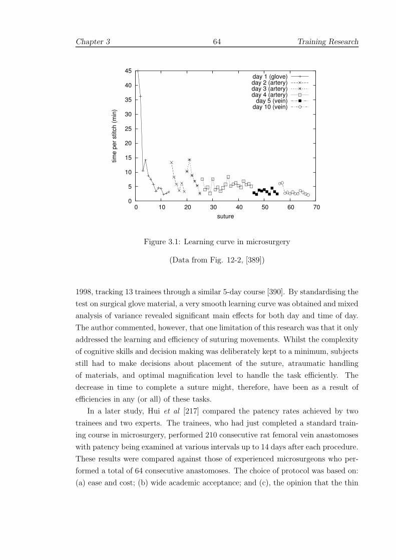
Chapter 3 64 Training Research
0
5
10
15
20
25
30
35
40
45
0 10 20 30 40 50 60 70
time
per s
titch
(min
)
suture
day 1 (glove)day 2 (artery)day 3 (artery)day 4 (artery)
day 5 (vein)day 10 (vein)
Figure 3.1: Learning curve in microsurgery
(Data from Fig. 12-2, [389])
1998, tracking 13 trainees through a similar 5-day course [390]. By standardising the
test on surgical glove material, a very smooth learning curve was obtained and mixed
analysis of variance revealed significant main effects for both day and time of day.
The author commented, however, that one limitation of this research was that it only
addressed the learning and efficiency of suturing movements. Whilst the complexity
of cognitive skills and decision making was deliberately kept to a minimum, subjects
still had to make decisions about placement of the suture, atraumatic handling
of materials, and optimal magnification level to handle the task efficiently. The
decrease in time to complete a suture might, therefore, have been as a result of
efficiencies in any (or all) of these tasks.
In a later study, Hui et al [217] compared the patency rates achieved by two
trainees and two experts. The trainees, who had just completed a standard train-
ing course in microsurgery, performed 210 consecutive rat femoral vein anastomoses
with patency being examined at various intervals up to 14 days after each procedure.
These results were compared against those of experienced microsurgeons who per-
formed a total of 64 consecutive anastomoses. The choice of protocol was based on:
(a) ease and cost; (b) wide academic acceptance; and (c), the opinion that the thin
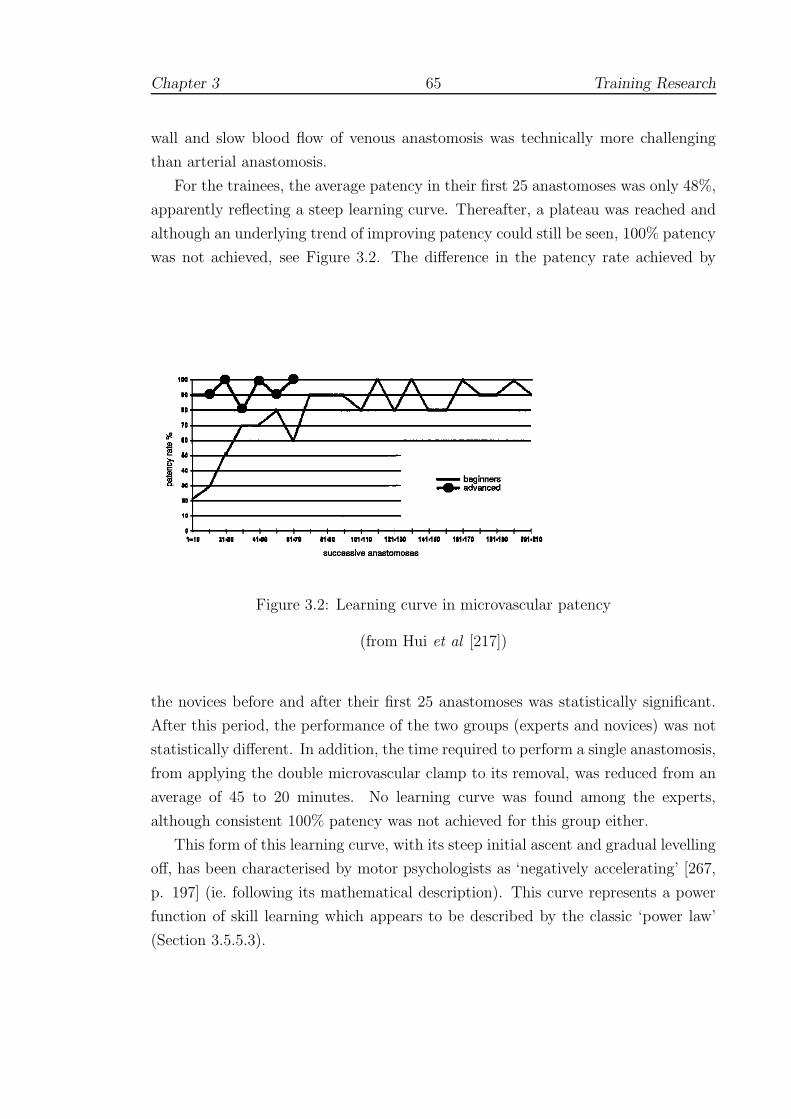
Chapter 3 65 Training Research
wall and slow blood flow of venous anastomosis was technically more challenging
than arterial anastomosis.
For the trainees, the average patency in their first 25 anastomoses was only 48%,
apparently reflecting a steep learning curve. Thereafter, a plateau was reached and
although an underlying trend of improving patency could still be seen, 100% patency
was not achieved, see Figure 3.2. The difference in the patency rate achieved by
Figure 3.2: Learning curve in microvascular patency
(from Hui et al [217])
the novices before and after their first 25 anastomoses was statistically significant.
After this period, the performance of the two groups (experts and novices) was not
statistically different. In addition, the time required to perform a single anastomosis,
from applying the double microvascular clamp to its removal, was reduced from an
average of 45 to 20 minutes. No learning curve was found among the experts,
although consistent 100% patency was not achieved for this group either.
This form of this learning curve, with its steep initial ascent and gradual levelling
off, has been characterised by motor psychologists as ‘negatively accelerating’ [267,
p. 197] (ie. following its mathematical description). This curve represents a power
function of skill learning which appears to be described by the classic ‘power law’
(Section 3.5.5.3).

Chapter 3 66 Training Research
3.1.3 Laparoscopic hernia repair
Bencini obtained indirect information for laparoscopic hernia repair by the outcomes
on patients undergoing laparoscopic hernia repair over a 3 year period at the Florence
Main Academic and Teaching Hospital in Italy [54]. For analysis, the 64 patients
that were treated consecutively during this period were retrospectively divided into
two groups: group 1 included the first 32 patients, and group 2 included the second
32 patients. The results showed that operative times and complication rates were
similar, but that bowel injuries were significantly more common in group 1, including
patients who were converted to treatment by open surgery. It was concluded that
a learning curve was manifested in the decrease of conversions and bowel injuries.
Also, it was thought that with improved skills and experience, patients with larger
defects probably become candidates for laparoscopic repair.
3.1.4 Biopsy
The initial learning curve for performing biopsy appears to follow a similar (‘neg-
atively accelerated’) trend. In the review of sentinel node biopsies by Tafra [413],
only two of the four multicentre trials examined provided reliable learning curves but
these showed a decrease in the false negative rate to 5% after 20 to 30 procedures are
performed. Despite several possible confounding factors, the author concluded that
the evidence was compelling that surgeons should obtain a minimum experience of
20 cases.
Researchers at the H. Lee Moffitt Cancer Center have adopted a more radical
solution to the problem of assessing outcomes whilst protecting patients from unnec-
essary risk and surgeons from potential legal consequences. Participating surgeons
are requested to send their outcomes data of sentinel lymph node (SLN) mapping
and biopsy to a secure database via the web [1]. The information is reviewed and
analyzed to provide the surgeon with the results of the learning process, but the
results are not open to outside scrutiny. Cox et al [116] have shown that out of
1,880 cases performed by six surgeons at the Moffitt Cancer Center, an average of
22 cases was needed to achieve a 90% success rate of finding an axillary SLN, and
63 cases were needed for a 95% success rate (a result which echoes the findings of
[115]).
Erratic learning curves from many of the outside surgeons led to examination
of surgical volume as a potential factor affecting failure rate. The Surgical Volume
Index (SVI) was defined as the average number of cases performed in a 30-day

Chapter 3 67 Training Research
period and was calculated for the entire group of 16 surgeons. It was observed
that surgeons with SVI<3 had an average success rate of 86.23% which rose to an
average of 97.81% for those surgeons with SVI>6. Cox et al report that one surgeon
whose error rate did not improve as expected, sought reattendance of the lymphatic
mapping course, after which there was substantial improvement. The authors intend
that the tracking of errors in this format should allow individual surgeons to engage
themselves in a continuous quality improvement process [116].
3.2 Military training research
3.2.1 The US Army Research Institute (ARI)
The ARI has tested numerous devices over the past decade. These trials are often
at the level of field units (platoons, brigades etc.) in which the old form of training
— possibly another simulation — is compared to the new. Examples of research
include evaluation of situational awareness [270], new equipment (eg. night vision
goggles [319]) and collaborative working on SIMNET and other systems [397]. A
few studies aimed at rotary-wing flight simulation are reported below. The scale and
frequency of these studies has also prompted the issue of various guidelines, which
are discussed in Section 3.3.1.
3.2.2 Transfer of training research
In 2002, Stewart et al [396] published the results of a number of trials to develop
rotary-winged aircraft simulators undertaken at the ARI throughout the 1990s. The
authors observed that the situation still persisted from the 1970s that more atten-
tion was often paid to the development of simulators than to supporting training
programmes. Simulator developers, perhaps best described as ‘artisans’, had shown
considerable skill in getting devices to perform realistically, but had not contributed
to the knowledge base for the functional requirements of effective simulation. In
short, more research into training effectiveness was needed.
In the sequence of transfer of training (TOT) studies undertaken by the group,
the authors sought to establish transfer effectiveness ratios (TERs, see 3.4) for a
hydraulically-driven simulator based upon the UH-1 helicopter. Positive TERs were
reported for most (but not all) flight manoeuvres pre-trained in the simulator and
students in the simulator group required fewer iterations than control participants to
reach proficiency. As the visual display and flight modelling systems were upgraded,
Chapter 3 68 Training Research
greater TERs were observed, and the differences among groups tended to become
more significant, particularly for less experienced trainees. The authors concluded
that a combination of synthetic flight simulation and criterion-based training during
the primary phase of rotary wing training had the potential for considerable savings
in training time and costs.
3.2.3 PC-based simulators
Increases in computing power and the falling cost of hardware have driven a recent
trend to adopt lower cost PC-based systems. As with the earliest fixed-wing simula-
tors, one area where this approach is likely to help is with flight instrument training.
Research has shown that the PC-based Aviation Training Device (PCATD) is as
effective as procedural instruction for fixed-wing aircraft instruction (at a fraction
of the cost) with TERs of 0.16–0.39 (see Equation 3.10, below) being reported. A
further study found that just one hours’ training allowed an experimental group to
perform significantly better in level flight and turning manoeuvres than an untrained
control group.
To get FAA approval, however, the physical controls of the simulator need to be
able to mimic many flight characteristics. Johnson and Stewart [223] also wanted
to test whether similar performance benefits might be obtained for rotary-winged
simulations. The authors undertook two phases of ‘utility testing’, the first with
experienced flying instructors; and the second, with students. A total of 16 par-
ticipants were included which was thought to be optimal to detect most usability
problems. Testing was performed by extensive questionnaire. The authors reported
good agreement between the groups, with general approval for instrument training,
and several criticisms for lack of flying control, especially in hovering.
In a further study, Stewart et al [395] wished to compare training using the
older Synthetic Flight Training System (SFTS) against a newer PC-based Primary
Skills Trainer (PST). In contrast to the PST, the older system (developed in the
1960s) provided a hydraulic platform (requiring expensive maintenance), but no
visual feedback. A total of 38 flying students were allocated to a total of 30 hours
simulator training in either the SFTS or the PST and then tested after 20 hours
instruction in the TH67 Helicopter. Although no difference was found between
the groups, the authors concluded that students appeared to the find the older
system more difficult to handle and that the PC-based system was clearly superior
economically.

Chapter 3 69 Training Research
3.3 Validity and Reliability
3.3.1 ARI simulator research guidelines
The frequency of non-significant and spurious results has prompted the ARI to
publish guidelines for testing new simulator devices. Boldovici et al [65] pointed
out that where conventional training methods were being compared to new methods
(often under different conditions), the meaning and power of these tests was doubtful
and, moreover, acceptance of the null hypotheses should not necessarily follow. The
authors advised that:
• Testing the hypothesis that one kind of training is superior to another by
a stated amount, rather than testing the null hypothesis of equality reduces
the chance of making a Type II error, that is, of erroneously concluding the
compared kinds of training are equally effective. Using confidence intervals
also improves the interpretation of a null hypothesis result.
• Increasing the statistical power of a test does not necessarily require increasing
the sample size. Decreasing the variance of scores within compared groups
and randomizing variables that we cannot measure or control also results in
increased power.
• The results of tests given before the training in an evaluation begins (pretests)
help establish whether the compared groups differed in proficiency or in other
ways that might confound evaluation.
• Amounts of training exert strong effects — training evaluations that do not
equalize or systematically vary amounts of training leave open to question
whether the observed effects were due to the compared kinds of training or to
differences between their amounts.
• Scores from tests given immediately after training are not reliable predictors
of future performance, and tests given at various intervals after training will
yield various results. The reliability and validity of scores will increase with
the use of multiple post-tests, as will the validity of inferences we make from
the scores.
Above all, the authors were concerned that the reliability of any given test should
be established, so that valid statistical inferences could be drawn. In particular,

Chapter 3 70 Training Research
they emphasised that reliability gives an upper bound on transfer to the target
environment. Following the methodology of Ghiselli, published in 1964, if reliability
is expressed as a coefficient between zero (unreliable) and one (reliable), then:
predictive validity ≤√
reliability (3.1)
The appearance of Equation 3.1 seems surprising at first sight and references in
the simulation literature are scarce. To understand the connection between reliabil-
ity and the various forms of validity, therefore, it is necessary to give some of the
background theory developed in social psychology over the past few decades. This
work is introduced below.
3.3.2 Validity and reliability
3.3.2.1 Measurement
To understand relation 3.1, a good starting point is the observation by Carmines
and Zeller [88] that the process of measuring a given variable is far from simple. In
particular, measurement is not just associated with grading objects or events, but
must be ‘viewed as the process of linking abstract concepts to empirical indicants.’
In other words, issues of validity and reliability are uniquely tied to the theoretical
considerations which led to the empirical observations in the first place. It will
be seen that reliability and validity are in fact tied to the nature of random and
non-random errors which are inevitably introduced into most analyses.
3.3.2.2 Types of error
Reliability concerns the extent to which an experiment, test or other measuring
procedure yields the same result on repeated trials. A given result always contains
a certain amount of random error and, for this reason, reliability may be defined as
inversely proportional to the amount of random error. Validity, on the other hand,
is related to the amount of non-random or systematic error which is introduced,
usually due to some theoretical issue since the question must often be asked: ‘valid
for what purpose?’ A simple example may help here. Suppose a yardstick1 were
used to measure someone’s height in metres. The result may be reliable, since re-
measurement always yields (nearly) the same result, but it is quite invalid, since the
aim was to measure height in metres.
11 yard ≈ 0.9144 m

Chapter 3 71 Training Research
3.3.2.3 Assessing reliability
To understand the assessment of reliability, it is useful give a brief derivation of
Equation 3.1. Using classical test theory [88, 304], we can write:
X = t + e (3.2)
where X is the observed score, t is the true score and e is due to random error. If
e is truly random, we can predict (over an infinite series of observations) that the
expected error, ie. the mean error, will be zero and that we should therefore obtain
the true value. Also, we expect the following correlation coefficients (ρ) to be zero:
ρ (ei, tj) = ρ (ei, ej 6=i) = 0 (3.3)
that is, no correlation should exist between a given error and true score term, or
between two error terms. Extending this to a given population, we have:
V ar(X) = σ2X = V ar(t + e) = V ar(t) + V ar(e) (3.4)
since, given our assumptions, covariance terms disappear.
Rearranging, we can define the reliability of X as ρX where:
ρX =V ar(t)
V ar(X)= 1 − V ar(e)
V ar(X)(3.5)
Hence if all the observed variance is contaminated with random error, then ρX =
1 − (1/1) = 0 else if there is no random error, ρX = 1 ie. 0 ≤ ρX ≤ 1.
To assess reliability, it is supposed that ‘parallel measures’ of the same true score
can be obtained. That is, we assume we can get repeat observations Xi of the true
score t, which vary by a random error ei and where the error is normally distributed
with a mean of zero and variance V ar(ei). In the simplest case, we can write
X = t + e, X ′ = t + e′, where σ2e = σ2
e′ (3.6)
The correlation between parallel measures (ρXX′) can then be expressed in terms of
the variances, as:
ρXX′ =σXX′
σXσX′
=σ2
t
σ2X
=V ar(t)
V ar(X)(3.7)
(again, given our assumptions in Equation 3.3).
Equation 3.7 is important since it allows an estimate of the variance of the true
Chapter 3 72 Training Research
score and also shows that the correlation between parallel measures is simply the
reliability of X, ie. ρX = ρXX′ . Although only two observations are needed, the
more separate measurements are taken, the higher the accuracy of our estimate
and, therefore, the greater the reliability. If an infinite number were available, and
a correlation matrix constructed, it is possible to show that [304, p.220]:
ρtX =√
ρX =√
ρXX′ (3.8)
where ρtX is the correlation between the true and observed scores and ρXX′ is the
reliability of parallel measures. But since ρXY , the correlation between observations
with our current scale (ie. X) and an unspecified second measuring instrument, Y ,
can never be more reliable than ρtX , we have (using Equation 3.8):
ρXY ≤ √ρXX′ (3.9)
and hence the predictive validity (if Y is the criterion measure; see 3.3.2.4 below) is
bounded by square root of the reliability of parallel measures (Equation 3.1).
It is useful at this point to describe some of the ways that reliability may be
assessed, and the relative strengths and weaknesses of these methods [88]:
1. Retest method: One of the easiest ways to estimate reliability is to retest the
same people after a period of time. An interval of two weeks may be optimal,
though this is not without contention. Too short a period will risk inflation
of the reliability estimate due to memory effects, whilst longer periods will
introduce greater risk of outside influences, changes in attitudes etc., although
this would seem to be more easy to control in tests of skill. A more serious
drawback is that researchers are only able to obtain measures at one point in
time, since multiple retests are expensive to obtain and often impractical.
2. Alternate Form method: As above, the same participants are retested, but an
alternate form of the test is used. The main benefit is that memory effects
are reduced. But besides the difficulty of devising the new test, a significant
problem is that two testing administrations do not allow an estimate of true
change given the presence of unreliability in the measure.
3. Split-halves method: Instead of repeating the test, the test items are randomly
divided and administered to two separate groups. The results of the two groups
can then be correlated eg. using the Spearman-Brown prophecy formula. The

Chapter 3 73 Training Research
main difficulty is then the division of test items, which will tend to influence
the correlations generated.
4. Internal consistency method: This method avoids splitting or repetition of
tests by using measures of internal consistency, eg. Cronbach’s alpha, between
test items. It has been shown that alpha is a lower bound to the reliability
of an unweighted scale of N items, that is ρX ≥ α. Thus, in many situa-
tions, alpha provides a conservative estimate of reliability. This is not true,
however, if there are systematic differences (eg. learning effects) between par-
allel measurements [88, p.47][304, p.244]. It might be anticipated, therefore,
that in surgical simulations, this method would be valuable for assessing inter-
rater reliability (see 2.3.4.3), but would be more of doubtful use for assessing
inter-trial reliability (cf. McCluskey et al, 2.3.2.4).
3.3.2.4 Criterion validity
If the reliability is known, Equation 3.1 gives an upper bound for validity, but
establishing (a non-zero) validity is much less straightforward. Carmines and Zeller
refer to the principal form of validity as criterion validity, which encompasses both
predictive and concurrent validity (as defined in Appendix A.1). In both cases
an intuitive and obvious external criterion exists either at the present time (hence
concurrent) or can be tested in the future (hence predictive). A written driving test
is validated, for example, if it predicts correctly how well people can drive a given
type of vehicle. An important feature of this kind of test is that there is a strong
degree of correspondence such that correlation coefficients should be significant.
Indeed, a good correlation is the only requirement for this type of validity and it
should be noted that there may be many equally valid criteria for assessment. One
problem, however, is that the validity and reliability of both the test and the criterion
assessment need to be verified. Another, at least in the social sciences, is that the
opportunity to use such tests is rare.
3.3.2.5 Content and construct validity
An alternative is to examine content validity of an experiment, in which some at-
tempt is made to specify the range of a particular test domain ie. a ‘universe of
content’ needs to be agreed upon. This too presents considerable difficulties. As an
example in social psychology, Carmines and Zeller suggest the problem of measur-
ing an abstract concept such as self-esteem. There are certainly no obvious external
Chapter 3 74 Training Research
criteria and it would seem to be impossible to describe the universe of experience.
If it is proposed, however, that some novel scale of self-esteem may be related to the
number of activities (clubs, societies) that someone takes part in, we may then form
the construct that this new measure is related to ‘number of activities’. To give a
more formal definition:-
Construct validity ‘is concerned with the extent to which a particular
measure relates to other measures consistent with theoretically derived
hypotheses concerning the concepts that are being measured’ [88, p.23]
In this case, however, the occurrence of a strong correlation in one test is not suffi-
cient to validate the construct. Instead, the process of construct validation should
involve a series of distinct steps, which allows a period of deliberate reflection.
Carmines and Zeller suggest the following ideal path: first, that the theoretical
relationship must be specified; second, that the empirical relationship between the
measures and concepts must be examined; and finally, that the empirical evidence
must be interpreted in terms of how it clarifies the initial construct. In effect, a
framework of theory and hypotheses must be built around the construct which is
only considered valid if a pattern of consistent findings emerges. Indeed, a separate
construct is also usually needed — and embedded within the framework of theory —
to satisfy researchers that the content of the test is sufficiently wide [304, p.310]. By
necessity, this will require endorsement from different researchers after completing
a number of different studies.
3.3.2.6 If the construct is not valid
If inconsistencies arise, the researcher typically concludes that the construct asso-
ciated with the main concept is not valid ie. the measure is not appropriate for
its intended purpose. The construct may be reformulated (in which case, the pro-
cess of validation must begin again) but, crucially, previous research employing that
measure of the concept must be called into question. Unfortunately, several other
avenues of interpretation exist:-
• Perhaps the new construct is reasonable, but it is not positively correlated
with the measured variable. In the ‘self-esteem’ example, it may be concluded
that the number of activities is not correlated (though something else may be).
• That the test was not conducted properly or that statistical inferences used
were inappropriate.

Chapter 3 75 Training Research
• Perhaps the test lacks construct validity due to the confounding effects or
unreliability of other variables in the analysis.
3.3.3 Validity and reliability in simulation
This section has described at least two important relationships, which may be sum-
marised as:-
1. Equation 3.1, which asserts that predictive validity is bounded by the reliability
of measurement. Where doubts about the reliability of a test exist, the validity
is effectively zero.
2. An implied hierarchy of validities: predictive and concurrent validity are the
most powerful forms, but are usually difficult to assess (and likewise, content
validity). Construct validity is often the best alternative, but, in turn, requires
careful validation through extensive research.
In Chapter 2, numerous systems were reviewed in which construct validity tests of
surgical simulator systems were reviewed. In general, there was good agreement
that the performance of novices could be distinguished from that of experts and we
might therefore suppose that the construct of simulator performance as a measure of
surgical skill is valid. Where tested, however, the performance of intermediate level
groups was not nearly so clear: see ADEPT (2.2.2), ICSAD (2.2.3), MIST (2.3.2.2),
LapSim (2.3.2.3), ProMIS (2.3.2.4), Blue Dragon (2.3.4.2), GI Mentor (2.3.4.3); and
was sometimes markedly worse than expected eg. CathSim (2.3.5.2) or even entirely
inverted eg. Figert et al [157] (2.3.3). It is argued that these anomalies give sig-
nificant cause for concern with respect to the construct validity approach. At the
very least, some level of reflection (consistent with recommendations in 3.3.2.5) is
needed. Before returning to this subject in Section 3.6, however, it is necessary to
bring in further background material from other psychological perspectives. Section
3.4 discusses attempts to use deliberate training methodologies in simulator eval-
uation and Section 3.5 gives an introduction to issues motor learning psychology
generally.
Chapter 3 76 Training Research
3.4 Models of transfer
3.4.1 Transfer effectiveness
Bradshaw et al have observed that the theory of ‘identical elements’ remains nearly
as pervasive now as when originally advanced by Thorndike in 1906. The main
tenet of his theory was that learning was not general — transfer could only occur
where identifiably similar elements of the task occurred. In modern testing, however,
the issue of which elements to vary in psychological research remains unsolved. A
common approach in aviation is to use subjective estimates of transfer, in which
experts are asked to complete detailed questionnaires on given simulators. Although,
good agreement can sometimes be found, the results are usually less than perfect
[67].
To avoid such subjective measures, hundreds of transfer models (eg. Equation
2.1), have been proposed since the earliest LINK trainers of the 1940s [195]. One
which is still commonly used is the Transfer Effectiveness Ratio (TER), which may
be given as:
TER =Taskc − Tasks
Tsim
(3.10)
where Taskc and Tasks are respectively the mean time (or number of trials)
required for the conventionally- and simulator- trained groups to reach some criterion
level on the target task, and Tsim is the mean time (or number of trials) that the
simulator group spent in the simulator.
A common problem with these models is that evidence to support particular
transfer functions has proved to be fragmentary, although Roscoe and Williges [343]
argued that the shape of these functions seems to be supported even if the specific
values are not, see Figure 3.3. Using an ‘incremental’ variant of TER (ie. ITER
in the figure), for example, this figure purports to show that training effectiveness
diminishes after around 5 hours’ practice in the GAT aviation trainer.
In the ARI guideline document [65], Boldovici et al demur from presenting such
figures for several reasons. Firstly, since the reliability of the terms in the numerator
is often not sufficiently well established (or published), the numerator may effectively
be taken to be zero. Secondly, since the TER does not stem from a controlled study
design, the results may be masked by practice or unrelated effects. The authors’
conclusion was frank:
Our advice is to avoid using transfer formulas and transfer-efficiency

Chapter 3 77 Training Research
Figure 3.3: Transfer effectiveness for the LINK Gat-1 trainer
(from [343])
formulas such as the TER. Use conventional analyses of raw scores
instead. . . when evaluators do not report conventional analyses of raw
scores, we wonder, and hope you will too, whether the evaluators don’t
know any better. . . the light shed by their work on transfer is not worth
the candle.
The justification for seeking expressions such as TER is that they seem to offer a very
straightforward method of calculating potential cost benefits. To obtain a reliable
estimate of TER, however, identical groups each ideally of 30 or more students
must be trained over a period of months to a high degree of proficiency. In other
words, a paradox arises that accurately assessing the TER becomes a very expensive
proposition [67].
3.4.2 ‘Above Real-Time Training’
Whatever the doubts about particular models of transfer (see 3.4), studies have
consistently shown that simulator training has led to improved performance for
aviators, especially in fixed-wing aircraft. Simulators have also, in general, been
more effective for practising parts of the task, particularly take-off and landing,
rather than the whole experience. Gains on transfer testing, however, have usually
been shown to level off after about 25 missions [89].

Chapter 3 78 Training Research
An intriguing extension of research into transfer is the development of ‘Above
Real-Time Training’ (ARTT). During the late 1960s and early 1970s, test pilots
complained that real life events seemed to occur at a quicker pace than in the
simulator, even though the simulator events were running at the same speed as
real life events. In response, researchers accelerated the simulations and pilots soon
endorsed the change, claiming it more closely approximated real life conditions.
Transfer studies in gunnery simulation, air traffic control and aviation tactics have
subsequently endorsed that ARTT-trained personnel are better able to cope with
emergency actions when tested in virtual or real world situations running in the
normal time frame [276].
3.4.3 Quasi-transfer
3.4.3.1 Early research
Some of the earliest work in quasi-transfer (QT) was undertaken by Lintern et al
during the 1980s [414]. In principle, the idea is very simple: if a particular feature of
a simulator is to be assessed, two groups are trained, one with and one without the
feature. In normal transfer experiments, both groups would then be tested to some
criterion level of performance in the real task, aeroplane etc. In QT experiments,
however, the groups are tested in a simulator, which may be the same as used for
training or re-configured to have the feature of interest activated or deactivated,
according to the aims of the evaluators.
For many years, flight training research proceeded under the implicit assumption
of correspondence between transfer and QT. Using landing as the criterion task,
Taylor et al [414], found that results in testing this assumption were mixed. Low
levels of scene detail (very basic, given the graphics capabilities of the time) were
found to show some degree of correspondence in student landings of real aircraft,
although this factor was not significant in the QT results. By contrast, augmented
displays, in which some groups were aided by ‘F-shaped’ poles to either side of the
virtual landing strip did not seem to aid transfer but showed significant effects in
some of the measured parameters of the QT tests. These results were by no means
convincing. Given the limitations of simulator fidelity at the time and the difficulty
of assessing the same characteristics in genuine aircraft (students were rated by their
instructors), the results did give some encouragement.

Chapter 3 79 Training Research
3.4.3.2 Recent QT designs
Using more capable tracking methods, such as the Global Positioning System, and
more faithful simulations, some of these issues have been overcome. Recent concerns
in the literature have focused on motion cueing, which remains limited compared to
the aircraft-motion in real space. Moreover, due to the digital simulation process
in the host computer, the simulated aircraft output (the visual displays, the instru-
ments, and the motion system) was found to be disturbed by different time delays,
with consequent negative training results [213].
Concerns by the FAA over the effects of these disturbances has led to the funding
of a very large project at the American Institute of Aeronautics and Astronautics
(AIAA) [84, 85]. Using a QT design, ‘motion’ and ‘no-motion’ trained groups were
found to have similar results in testing, and later enhancements appeared to cause
the ‘motion’ group to overreact. Only in reaction to certain adverse conditions,
did motion cueing appear to help. Elsewhere, the technology was not thought to
have provided sufficient motion to be effective. The authors also acknowledged that
although the QT design still needs to be thoroughly validated, empirical support
has been found by many years’ usage as a stand-in for the aircraft in total flight
training.
An interesting variation, known as backwards quasi-transfer, was demonstrated
to be effective by Goettl [179]. In this study, three training groups were given
simulator-based flight instruction. The first group received whole-task training, the
second group received part-task training concentrating on the critical components of
the task and the third group undertook part-task training on non-critical elements
of the task. The groups were then tested on a series of VR ‘slalom’ courses. The
first two groups performed equally well, and both were significantly better than the
third group. Goettl and Shute [180] argued that assessment of backward transfer is
crucial for identifying the relevant and irrelevant component tasks: elimination of
component tasks irrelevant to the criterion task should render the part-task training
regime more efficient.
In some circumstances, especially wherever hazards in field testing might arise —
such as in simulating live fire — QT exercises may be the only choice for estimating
transfer. Boldovici et al pointed out that as the fidelity of simulators has improved,
the QT protocol has developed three important strands: firstly, for estimating how
training and testing conditions affect retention and transfer; secondly, to permit the
collection of repeated measures by repetitions of individuals’ or units’ performance,
so that test reliability (and hence statistical power) can be increased; and finally, to

Chapter 3 80 Training Research
help refine future experimental designs [65].
3.4.3.3 QT in surgical simulation
To the author’s knowledge, only one QT experiment has been attempted within
the field of surgical simulation. In previous work, Strom et al [400] verified that the
Procedicus Key Surgical Activities (KSA) simulator produced performance gains (in
terms of time and efficiency of movement) after one hours’ practice on both the KSA
and MIST devices; the KSA simulator provides similar targeting exercises to MIST,
but also provides haptic feedback and realistic anatomical graphics. More recently,
however, Strom et al [401] used a QT design to assess training with the Procedicus
MIST, KSA and Virtual Arthroscopy (VA) Shoulder devices against performance on
another simulator, the VA Knee device. A post-test only design was used, in which
the order of training/testing is given in Table 3.1.
Experimental group Control group
1 hours’ training on Pro-cedicus MIST, KSA andVA Shoulder devices
no training
post-test, VA Knee device
Table 3.1: Quasi-transfer test by Strom et al
The aim of this study was to test the assumption that performance in the Pro-
cedicus VA Knee Simulator would not improve after training of novices in other
simulators where visuo-spatial components were dissimilar. Arthroscopic surgery
was chosen as the test case because it is generally considered a difficult endoscopic
procedure, since movements are performed in a very complicated anatomical en-
vironment. The comparison of the two groups did not show significant difference
between the groups and the failure to find correlation between scores on the various
devices appeared to provide support for the authors’ claim.
The study appears to violate two basic premises, however. In the first place, a
non-significant result does not lend support for any particular hypothesis2, since the
experiment itself may be flawed [65, 250]. In particular, the probability of Type II
errors (accepting non-significant results by mistake) does not appear to have been
2To give a common analogy: claiming that a non-significant result is evidence of the nullhypothesis, is to equate a ‘not guilty’ verdict with innocence [297]. In most legal systems, however,only ‘guilt’ is ever established.
Chapter 3 81 Training Research
appreciated (see 3.3.1). Secondly, the QT section of the study attempts to compare
the ‘no training’ condition with that of training on the MIST/VA Shoulder/KSA
simulators by testing with a different simulator (the VA Knee). A more appropriate
QT design, eg. following the work of [414], would have compared training on the VA
Knee simulator with training on the other simulators, by post-testing both groups
on the VA Knee device.
3.5 A psychological perspective
3.5.1 Ability and skill
Earlier in this document, it was conveniently assumed, following the suggestion by
Cuschieri (see 2.2.1 and [356]), that ability was something innate and unchangeable,
whilst skill was some property which could be developed. This was a reasonable
starting point, but it is now certain that abilities do change (see [423]) and, in the
face of this, it is disconcerting that no definition of ‘skill’ or its acquisition has even
been attempted.
The historical review by Adams [31] pointed out that analysts have been strug-
gling with a definition of skill for decades, although that proposed by Pear in 1927
seems to have left its mark in the literature: ‘The concept of skill which is proposed
is that of integration of well-adjusted performances, rather than a tying together of
mere habits. In Man, at least, skill is acquired and fused with natural aptitude.’
Pear later adapted his definition to state ‘muscular performances ’, but psychologists
ever since have debated whether ‘skill’ should include cognitive as well as physical
abilities. Adams preferred to leave a more open viewpoint and listed three important
properties:
• Skill is a wide behavioural domain, which has included a wide variety of be-
haviours which are nearly always complex.
• Skill is learned. A useful clarification (especially for simulator research), was
offered by Guthrie in 1952: ‘skill consists of the ability to bring about some
end result with maximum certainty and minimum outlay of energy’, but in-
vestigators should not be constrained to consider only the highest grades of
performance.
• Goal attainment is dependent upon motor behaviour. Any behaviour that
is skilled involves combinations of cognitive, perceptual and motor processes,

Chapter 3 82 Training Research
albeit with different weights depending on the task.
A brief survey of the psychology and psychomotor learning literature is given here,
firstly, so that the necessary concepts related to performance can be defined and
secondly, so that some of the design features of various simulators described in this
review can be reappraised.
3.5.2 Knowledge of results (KR) and performance (KP)
Edward Thorndike, one of the fathers of learning psychology, left a legacy which was
debated long after his death. His ‘Law of Effect’ supposed that a given subject has
many responses available in his or her repertoire, some of which occur in the learning
situation. Eventually one of the responses leads to reward and is strengthened,
increasing the probability of its occurring and being strengthened again. Learning
did not need the intervention of conscious thought processes, but was the automatic
strengthening of a habit connection between a stimulus and a response.
In one of his most famous experiments, blind-folded subjects were asked to draw
lines of varying lengths. To within a certain tolerance, 13% of the lines drawn were
‘correct’ in a pretest without KR. In the test phase, subjects were informed whether
they were right or wrong (ie. given KR) and the percentage correct rose to 54.5%
after 4,200 lines had been drawn. With practice repetitions alone, this percentage
remained unchanged over the drawing of a further 5,400 lines. Later work supported
this result and showed that KR given as a quantitative error produced even faster
learning [31].
In this experiment, the feedback was extrinsic (given externally by test super-
visors), since the participants were blindfolded, but had they been able to teach
themselves, feedback could easily have been intrinsic. Modern analysts continue to
emphasise the role of KR for motor learning (but see 3.5.8), but another valuable
technique is to give feedback on limb (hand etc.) movements (known as KP). Re-
search has consistently shown that the provision of error information is more effective
for facilitating skill improvement, although there is some debate as to the quantity
or quality of information provided. Also, feedback given when not requested, or in
too complex format, can depress performance [267, p.275–6].
By its nature, however, kinematic feedback is very difficult for performers to
assess themselves and is one reason why coaches and physiotherapists are needed.
KP is therefore nearly always extrinsic. Another important distinction is that KP
is usually independent of the results of the action (KR).

Chapter 3 83 Training Research
3.5.3 Individual differences
A good deal of the early research in motor psychology was focused upon the prob-
lem of assessing ‘individual differences’ (ie. abilities), to allow prediction of future
performance (of pilots, telegraphers etc.). The original contributions by Thorndike
(see 3.4 and 3.5.2) were reanalysed by Kincaid in 1925, who decided that no decision
could be made about individual differences unless common measures were used (see
[31]). The essentials of her findings were that:
• Scores were reliable, ie. scores on adjacent trials were highly correlated
• Correlations between initial and final performance were positive: subjects
tended to maintain their relative standing with practice
• Levels of initial performance and gain were negatively correlated: subjects
with higher initial performance learned at a slower rate.
• Means, variances and correlations say little about the absolute differences be-
tween the scores of each set. Kincaid used the coefficient of variation (standard
deviation divided by the mean) to adjust for this. Two-thirds of the studies
she reviewed had a smaller coefficient of variation by the end of practice.
A later reanalysis by Reed in 1931 was forced to concur: individual differences tended
to converge with practice. Despite a doubling of research efforts during the war, these
problems were not overcome and although a handful of motor trials appeared to be
valid for selecting pilots, greater weight was always given to printed tests. In the
decades following the war, the main contributor to this field was Fleishman, who
defined an extensive set of motor ability categories (reaction time, movement time
etc.) which are still in widespread use.
Magill [267] (p.224) has observed that researchers attempting the prediction of
future performance have taken three main approaches:
• Prediction from initial scores: in the classic study by Trussel [424], using 75
sessions to teach juggling, prediction of final performance (over the last four
sessions) using data from the first five sessions was little more than the odds
of flipping a coin. After 15 sessions, prediction rates improved to about 85%.
• Intertrial correlations: using a table format to plot correspondence between
trials, it was noted that adjacent trials were much more likely to be highly cor-
related than trials which are farther from each other. Again, future prediction
of performance from early scores was found to be unreliable.
Chapter 3 84 Training Research
• Stages of learning: various researchers have analysed motor learning with re-
spect to Fitts and Posner’s model of learning stages (see 3.5.4). In the study
by Ackerman [30], the three stages appeared to be related only to skills in
which the motor performance aspects of the task are critical for success, and
where cognitive requirements do not change in any of the contexts in which
the skill may be performed.
Ericsson et al regard the search for predictors from the initial assessment of ability
as essentially futile: expertise is much more closely related to other factors such as
teaching, motivation and, above all, deliberate practice. In their analysis of members
of the Berlin Music Academy, they point out that to reach the top of the profession
(concert musicians) requires a minimum of 10 years’ deliberate practice. Ability
and motivation are important, moreover, because they facilitate practice, rather
than providing a substitute. Practice must also be highly specific as a similar rule
of thumb is described for other skilled performers, such as chess masters. Grand-
masters practice and memorise game plans for many years before they can expect to
achieve success. As a result they display remarkable skills for recalling the position
of chess pieces after examining any board for a few seconds. That is, unless the
pieces are placed at random, in which case their performance is little better than
anyone else [148].
3.5.4 The acquisition of skill
There is is some agreement amongst researchers that the acquisition of skill can be
seen as phased process, albeit the phases are not always discrete. Fitts and Posner
[159] advocated three phases:
• Cognitive: perceptual cues have to be taught or explicitly learned, probably
in a simplified version of the task.
• Associative: responses that must be learned start to become readily available,
old habits are erased and errors are gradually eliminated.
• Autonomous: skills become automated, so that they require less cognitive
control and are less prone to error.
Rasmussen [328] also described three phases of knowledge states, using a systems
theory approach to provide a model of behaviours (see Appendix A.3). Like the
Fitts and Posner model, the higher levels demand a greater cognitive load, in which
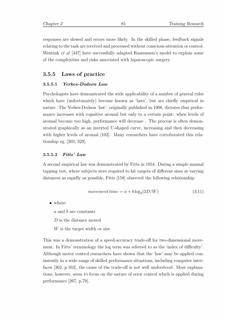
Chapter 3 85 Training Research
responses are slowed and errors more likely. In the skilled phase, feedback signals
relating to the task are received and processed without conscious attention or control.
Wentink et al [447] have successfully adapted Rasmussen’s model to explain some
of the complexities and risks associated with laparoscopic surgery.
3.5.5 Laws of practice
3.5.5.1 Yerkes-Dodson Law
Psychologists have demonstrated the wide applicability of a number of general rules
which have (unfortunately) become known as ‘laws’, but are chiefly empirical in
nature. The Yerkes-Dodson ‘law’, originally published in 1908, dictates that perfor-
mance increases with cognitive arousal but only to a certain point: when levels of
arousal become too high, performance will decrease . The process is often demon-
strated graphically as an inverted U-shaped curve, increasing and then decreasing
with higher levels of arousal [102]. Many researchers have corroborated this rela-
tionship eg. [203, 329].
3.5.5.2 Fitts’ Law
A second empirical law was demonstrated by Fitts in 1954. During a simple manual
tapping test, where subjects were required to hit targets of different sizes at varying
distances as rapidly as possible, Fitts [158] observed the following relationship:
movement time = a + b log2(2D/W ) (3.11)
• where:
a and b are constants
D is the distance moved
W is the target width or size
This was a demonstration of a speed-accuracy trade-off for two-dimensional move-
ment. In Fitts’ terminology the log term was referred to as the ‘index of difficulty’.
Although motor control researchers have shown that the ‘law’ may be applied con-
sistently in a wide range of skilled performance situations, including computer inter-
faces [362, p.163], the cause of the trade-off is not well understood. Most explana-
tions, however, seem to focus on the nature of error control which is applied during
performance [267, p.79].

Chapter 3 86 Training Research
3.5.5.3 The ‘Ubiquitous Law of Practice’
Observers have shown that extended practice for any particular skill pushes the
performance characteristics towards asymptote. Newell and Rosenbloom refer to
the ‘ubiquitous law of practice’: time per unit measured appears to follow a power
law, which can be expressed as:
T = A + β(N + E)−α (3.12)
where T is the time per unit (or trial), A is the level of asymptotic performance,
N is the number of trials performed and E is ‘experience’ ie. number of previously
completed trials; α and β are positive constants [295]. The authors reanalysed data
from many sources including perceptual challenges, simple motor tasks (tracking
a cursor, mirror tracing), problem solving (learning card games, decision-making
exercises), cigar manufacture and so on. For most results studied, a log-log plot
produced a reasonably straight line response, both with the power law and the
hyperbolic (α = 1) model.
It follows from this rule, that the time and efficiency metrics, which have been
used for many simulator studies (see 2.3), are reasonable choices for assessing ac-
quired levels of skill. It would also seem that these factors tend to improve purely
through practice ie. without extrinsic feedback on the nature of errors being com-
mitted (KR) or particular movement errors (KP). Thus, for training devices where
time-related scores are the main features being measured (eg. MIST and ICSAD),
improvement may be a by-product of trials undertaken. Caution is also therefore
required to ensure that technical aspects of the performance are not marred and that
illegal strategies are not permitted (as appeared to occur for the HOPS simulator,
see 2.4.2.2).
By contrast, the attempt to evaluate tissue distress in the BDI suturing simu-
lator was more ambitious, since it was aimed directly at assessing technique and
providing more appropriate KR (see 2.4.3.3). To demonstrate the ‘law’ of practice,
an example log-log plot is given in Figure 2.13(b) for the ‘tissue damage’ parame-
ter, and shows a reasonably well correlated fit to a hyperbolic power law function
(Pearson r2=0.872 (experts), 0.803 (novices); p < 0.005). The intersection of the
fitted straight line responses in this figure would occur at the 53rd trial, suggesting
that novices’ performance would rival that of the experts after a further 40 trials.
Since this point would lie in the region of negative ‘tissue damage’ (not defined), it
is argued that this value forms an upper bound for any possible intersection.
Chapter 3 87 Training Research
3.5.6 Plateaux
The existence of plateaux in learning curves was first recognised by skills researchers
working over a century ago. Training in telegraphy, and in particular, the recep-
tion of Morse code transmissions, often appeared to stall with no improvements for
many weeks. A possible explanation was that trainees arrived at points of transition
where sequences of information were forming letters, then words and finally phrases.
These findings are still described in many texts, despite the fact that replications of
the original experiments have failed to produce plateaux and that some psycholo-
gists have begun to doubt their existence [31]. The phenomenon has been observed
in many other experiments, although it remains unclear whether it proceeds from
instructional techniques, fatigue or lack of motivation [267, p.204].
3.5.7 Task classification
Several formal systems of task classification have been proposed. Gentile proposed
a comprehensive two-dimensional scheme, linking environmental context with inter-
trial variability [173]. The context described several properties:
• in closed motor skills, the relevant contexts are stationary, meaning that they
do not change position during the performance eg. picking up a cup whilst
sitting in a chair. The movement characteristics are invariant and can be
initiated at any time.
• in open contexts, the environment is moving, so that other people, objects and
surfaces must be accounted for eg. returning a ball at at tennis. Successful
action requires action at exactly the right moment.
• The forces, masses and other properties of objects that form the environment
also dictate the nature of the interaction.
Variability between trials implies that the environment changes between each trial,
so that different movements must be continually planned.
In a similar vein, systems theorists proposed that movements could either be
closed-loop or open-looped [31]. In open-loop activities, all the information to carry
out the movement must be contained in the initial instructions to the muscle ef-
fectors. In closed-loop performance, feedback is compared to some norm to enable
an action to be carried out. Central to the closed-loop theory was the explicit re-
jection of the Thorndikean idea of KR automatically producing learning. Instead,
Chapter 3 88 Training Research
motor learning was seen as a process of acquiring the capability to detect errors
intrinsically.
Schema theory was evolved in response to several perceived shortcomings of the
closed-loop theory [31, 361, 362]. Central to the idea was that motor functions are
provided by a range of different general motor programmes which must be adapted
when new circumstances arise. At its core, a motor programme describes a set
of rules for relative timing which must be invariant throughout execution of the
programme, although the speed of the programme as a whole can be increased or
decreased. In the classic experiment by Shapiro [379], walking up to about 6km/h
was found to have one set of invariant features, but beyond that, the motion changed
to a running action which had separate programme timings. The theory also accom-
modated response schema which allowed feedback to adjust movement if needed.
3.5.8 Training schedules, interference and retention
Perhaps the most important outcome with respect to motor programmes and schema
theory was the suggestion that the variation of schedules for feedback and training
could be productive. Several ground-breaking experiments were to follow. Shea
and Morgan [383] tested contextual interference effects of training to perform three
simple arm movement tasks, say A-C, as quickly as possible under different regimes.
Under the blocked regime, participants would perform blocks of task A, then a block
of task B and so on. Participants in the random group practiced exactly the same
number and type of movements, but in random order. Unsurprisingly the block
practice group performed significantly faster during training.
In testing, however, both groups were asked to perform in a blocked and random
format on two occasions: 10 minutes and 10 days after the final practice. Whereas
the randomly trained group appeared to stay at about the same level as their last
performance during tests, the people who had practiced under the blocked regime
showed sharply contrasting results. Tested in a blocked order, their results were
slightly worse; tested in a random order, their results were very much worse. In fact,
asked to recall these movements at random, the performance of the block-trained
group was worse than baseline performance prior to training.
Results such as these have generally been attributed to a class of phenomena
known as interference [332, 457]. One explanation that has been advanced is the
‘forgetting hypothesis’. This supposes that random practice during early rehearsal
causes people to generate and reconstruct action plans more effectively later, because

Chapter 3 89 Training Research
they were forced to forget (and recall) the movement more during practice. Another
possible explanation is that by varying the conditions of practice, transfer to the
target environment is more likely [55]. Other investigators have added to this picture:
blocked regimes may be more helpful for younger students or during early training
[381, 455]; interference effects would seem to be negligible for some, very simple
tasks [274].
The distribution of practice, using the amount of ‘rest time’ between sessions as
a treatment variable, has been shown to be another important variable for retention
and transfer. Data shows that massed practice tends to depress performance during
training and groups in which the training is distributed would appear to have dis-
tinct advantages during retention and transfer tests [384]. However, practicing well
beyond the first acceptable plateau region, or overlearning, has also been found to
increase retention for some tasks which are needed only sporadically. Schendel and
Hagman [358] used the example of machine gun disassembly and assembly to show
that if the number of trials required to perform the skill correctly once is doubled
(ie. 100% extra practice), performance is much more likely to be retained [41, 448].
Such performance schedules can, nevertheless, produce negative results: Shea and
Kohl [380] showed that in an exercise of pushing a lever with a specified force (175N),
a group which practiced using a range of forces was more accurate in retention than
an overtrained group who had only ever applied the correct force.
3.5.9 Feedback: scheduling and augmentation
3.5.9.1 The functions of extrinsic feedback
Schmidt and Wrisberg have described four important functions of extrinsic feedback
[362, p.283]:
1. Motivation: to energise learners into achieving the goals they have set for
themselves.
2. Reinforcement: to encourage more successful actions and to discourage less
rewarding ones.
3. Information: to indicate (directly or indirectly) actions for learners to control
movements or correct errors.
4. Dependence: feedback, of whatever quality, has dependency-inducing qualities,
especially if provided too often.
Chapter 3 90 Training Research
The authors also made an interesting additional distinction between descriptive and
prescriptive forms of external feedback, based on the research undertaken by Kern-
odle and Carlton in 1992 [232]. In this experiment, groups were given feedback on
their ability to make an overhand throw with the non-dominant hand, whilst being
blinded to the length of the throw by a wall. Groups who only received descriptive
feedback (the distance of the throw) were not as successful as those also received cues
to more effective throwing motions (advice attempting to ‘prescribe’ the motion).
This suggested that knowledge of results (KR) was not the most effective form of
feedback where complex movement activities were required. This result was echoed
in a clinical setting by Rogers et al [342], who found that training in knot-tying
exercises was enhanced when video-tapes of common errors and the correct method
of tying were shown first. Groups who saw only one or neither of the video-tapes
appeared to be equally disadvantaged.
These findings, and how they relate to training or simulation studies in general,
are described below.
3.5.9.2 Feedback schedules
The interaction between developing motor programmes and different levels of feed-
back has proved to be a fruitful area of research in motor psychology. In keeping with
the nature of closed-loop and schema theory, it seems necessary to allow trainees to
develop their own techniques of error detection. For example, providing immediate
feedback after each trial (100% KR) has been found to be counterproductive in tar-
geting [36] and tracking tasks [453]. There is also some evidence that trainees may
be sensitive to receiving feedback too soon after the end of the exercise, whilst they
may be trying to assimilate their next ‘action plan’. Various authors have found
that, by contrast, many students prefer to select feedback when they themselves
feel it to be needed [406]. The survey by Chiviakowsky and Wulf found that most
trainees preferred feedback only after a relatively successful trial [96].
It is notable that some simulator systems have drawn complaints from users for
providing too much feedback, making the system appear to be overly critical [417].
On the other hand, some researchers have found that more frequent feedback can
aid learners in acquiring complex skills, perhaps especially in the earliest phases.
Wulf et al [458] found that a 100% feedback schedule on a ski-simulator produced
more effective performance after 2 days’ training (and a retention test on the third
day), when compared to groups who only received feedback after 50% of trials. For
more experienced subjects, however, such constant feedback affects attentional cues

Chapter 3 91 Training Research
and may reduce performance [53].
More recent research, also using a ski-simulator, but without specific feedback
has revealed another interesting trend. Nourrit et al [303] found that training ses-
sions over a period of 13 weeks produced profound changes from a highly non-linear
damped movement initially to a much more linear function by retention testing at
5 months. During the transition stage, the 2 damping behaviours seemed to be
alternately exploited within each trial, indicating that trainees were selecting from
a number of possible strategies.
3.5.9.3 Augmented feedback
Given this picture, it is easy to see that care should be taken to provide only appro-
priate feedback. Intrinsic feedback, such as the use of force-feedback, is a common
area of difficulty: several studies have shown that where forces were absent (see
2.4.3.4 and 2.3.4) or inappropriate (eg. [85]), performance is detrimentally affected.
On the other hand, systems which have attempted to augment the level of extrinsic
feedback, such as the real-time ‘guide vector’ condition on the BDI simulator (see
2.4.3.3), have also had very limited success.
Too much additional feedback can lead to cognitive overload and is often un-
warranted. Given in this way, feedback can be demotivating or can lead to the
formation of a dependency: performance is raised during practice, but errors are
only aggravated if the training aid is removed. Devices for assisting weight-lifters
during practice, for example, have been shown to degrade test performance rather
than help [422] (and see [267, p.222,290]). Some researchers, however, have found
that concurrent visual feedback has been found to be beneficial in older adults (over
60) [454] and in rehabilitation settings [130].
3.5.9.4 Performance feedback
Investigations into the requirements for movement feedback (KP) are somewhat
rarer, but also seem to show that trainees find this extra information difficult to
assimilate, eg. [435]. Focusing directly upon the kinaesthetic properties of limbs
has been shown to have a negative effect upon training. In a balancing task on
a stabilometer platform, those participants who were asked to focus on their feet
performed significantly worse during retention testing than those whose attention
was focused upon an external marker [382]. In this test, the concurrent feedback was
not withdrawn during testing, but the external focus appeared to help by dissuading

Chapter 3 92 Training Research
participants from taking active control of their movements. It was also noted that
those members of external focus groups, after some practice and particularly during
the retention test, appeared to move the platform generally more smoothly than the
participants in the internal focus group.
3.5.10 Bimanual interaction
The importance of working with both hands has been stressed by a number of
authors [45, 160, 206, 225, 336] in both psychological and human-computer interac-
tion domains. Seay et al [370] nevertheless found that performance on the Virtual
Workbench varied using different types of devices but did not significantly improve
by allowing the use of both hands.
Direct or symmetric interaction, where both hands are essentially performing the
same manoeuvre either together or in cyclic order has been described by Swinnen
et al [64, 407]. Indirect, asymmetric interaction, however, was not fully appreciated
until the work of Guiard [190], which observed that most human actions are in fact
bimanual, even if only one hand appears to be playing a role. Writing a letter, for
example, involves many movements with the non-dominant hand to position and
frame the paper, see Figure 3.4, so that the actual working space of the dominant
hand is very small. Moreover, Guiard found that the subordinate hand often plays
a leading role, defining a broad ‘macro’ space within which the dominant hand is
able to act much more finely. The asymmetry of left and right-hand movements was
observed in a suturing task by Moody et al (see 2.4.3.4). This behaviour appears to
be natural, since the novices in this study tended towards the leading non-dominant
hand action pattern of experts after sufficient practice (although this was not entirely
perfected).
There is a further reason to believe that bimanual coordination is relevant here,
since several authors have reported that transfer is reinforced between limbs. In the
study by Weeks et al [445], a simulated prosthetic arm (worn by a fully able limb)
was used to examine possible directional effects of transfer by dividing participants
(42 able-bodied adults) into three groups: (i) practice with the preferred hand/tested
with non-preferred; (ii) practice with the non-preferred hand/tested with preferred;
and (iii) a control group (no practice). Although there was no significant bias to
transfer direction, transfer was observed in both directions with initiation time (time
to begin the task) showing immediate benefits. Interestingly, overall movement time
did not show immediate benefits, but did show significant improvements on retention

Chapter 3 93 Training Research
Figure 3.4: Asymmetric division of hand-writing task
(Left: finished letter, right: workspace used as seen from hidden carbon paper.From Guiard [190])
tests 24 hours later.
3.5.11 Part-task/whole-task training
For complex tasks (those which contain many component parts) which have little
organisation (whether the component parts are related), the part-task approach to
training provides a reasonable choice for breaking the problem into independent
parts ([267, p.238]). Three strategies are commonly employed:
• fractionization: the task is practiced on a limb-by-limb basis to target asym-
metric activities.
• segmentation: the task is broken into successive sub-tasks.
• simplification: the difficulty of all or parts of the task are reduced, by reducing
the load or speed required.
Simulators are readily adapted to the part-task approach for complex tasks [41, 180],
and reductions in complexity of all three types are often needed.

Chapter 3 94 Training Research
One study which is of further interest in this area lies in the area of Morse code
reception (see 3.5.3). Proficiency in this area is still very difficult to achieve and
has a high failure rate in terms of trainees. Some researchers have suggested that
practising the more difficult components earlier in the schedule has positive benefits
[138]. In the study by Clawson et al [103], training on the more difficult elements
first, however, was not found to be a useful strategy to teach letter discrimination.
A further experiment which broke the task into more difficult procedural aspects led
to slower performance and more errors in the practice phase, but performance on
individual sub-tasks was better retained upon a retention test 14 days later. This
group nevertheless found it harder to integrate the component sub-tasks.
3.6 Issues in simulator validation
3.6.1 Training effects and assessment
This chapter has investigated the nature of learning and assessment of skills from
several different perspectives. To resolve some of the apparent differences, this sec-
tion gives a synthesis, which is, in a sense, a continuation of the earlier attempt in
Section 2.5. The discussion here focuses upon the BDI suturing simulator described
in Section 2.4.3.3, but makes several recommendations which are intended to be
more generally applicable. The BDI study initially defined two broad objectives: to
assess whether surgical simulators can (a) measure surgical skills, and (b) be used to
train surgical skills. Yet, while these aims may seem to be distinct, improvements in
adjacent test scores suggest poor reliability (eg. see Figure 2.13(a)) and most skills
testing studies have shown similar practice/carry over effects. Another common
problem with the construct validity approach is that experts and trainees appear to
be converging fairly quickly: eg. after approximately 30 trials for the Stortz trainer
and perhaps 30–40 trials for the BDI study (see 2.5).
The authors of BDI study concluded that: ‘These data provide evidence that the
performance improves (at least transiently) during a single training session’ [308].
The study, however, followed a block training format, which has been shown to
give good initial results, but very poor retention (see 3.5.8). To determine whether
lasting learning has occurred requires a knowledge of learning curves, retention and
transfer characteristics which have generally been overlooked in most surgically-
based simulations. Indeed, it is instructive to reflect that, although construct validity
studies are common in social psychology, this kind of divergent validity approach (in
Chapter 3 95 Training Research
which groups are expected to diverge [304, p.93]) has rarely been adopted elsewhere
(see [415] and [53] for exceptions) and is unknown, as far as the author is aware, in
flight simulator studies. A number of possible explanations may be offered:
1. Quasi-experimental nature of the test: in the form of test shown for the BDI
simulator in Figure 2.13(a), several variables seem to be being manipulated:
(i) firstly, the experience of the participants has determined entry into the
novices’ or experts’ group; and secondly, the ‘explanatory’ variable (along the
baseline of the figure) is “number of trial”. Since the experimenter cannot
genuinely assign the first variable randomly, this test is therefore of the form
of a ‘quasi-experiment’. Leik [250] has pointed out that although such tests
are often the only practicable way of performing some experiments, and that
their external validity (‘applicability’ to the real world) is often very high,
circularities in the internal validity of these tests are common (see A.1 and
[233]). Several such tautologies can be described here. In the first place, an
appropriate null hypothesis might be stated as ‘there is no difference between
the expert and novice groups’ — although clearly this premise is false. This
suggests that the test is fundamentally weak, especially if the participants are
very experienced/inexperienced. Also, if the test were a reliable assessment of
surgical skill, the number of the trial should not be an issue, and it is unclear
why this variable is under test.
2. Criterion-based assessment is preferred: in other fields, where strong criteria
are available — such as, say, an ideal 4◦ descent path for flight simulations — it
is possible to assess trainees directly according to their performance. Although
several research groups have attempted to produce such ‘gold standard’ criteria
for surgical procedures (eg. using daVinci, see 2.3.6, or Markov modelling
[344]), the complexity of this problem does not suggest that easy solutions will
be forthcoming for surgical applications.
3. Usability studies: where experts and trainees have been tested together in rel-
atively short-term evaluational studies, the designers of the test have preferred
to obtain questionnaire responses rather than a direct comparison of test scores
(see 3.2.3).
4. Use of time and efficiency metrics: for most construct validity tests, signifi-
cant differences are only obtained for response variables which are based upon
time and efficiency metrics (including the ‘tissue-damage’ variable of the BDI

Chapter 3 96 Training Research
study). This suggests that only the proficiency of subjects is being monitored
and that the VR system is really only providing (expensive) clocking facilities:
training might, therefore, be as successful using less costly synthetic substi-
tutes. One exception to this pattern was the real-time guide vector condition
of the BDI study, which despite an interesting effect upon performance, did not
produce any lasting benefit. (This finding is in line with other motor psycho-
logical research, which suggests that such feedback can produce dependency,
see 3.5.9.)
5. Power of the test: researchers at the ARI and elsewhere are emphatic that
the statistical power of the test should be estimated beforehand and stated.
This requires that the reliability of the test should be established, possible
confounding variables should be controlled and, ideally, that some specified
amount of learning should be intended. Given the extraordinary length and
variety of surgical training, however, the power of any particular simulator test
would be very difficult to foresee.
3.6.2 Implications for construct validity testing
In Section 3.3.2.5, it was argued that construct validity requires a rigid framework of
theory and hypotheses which must be widely tested to be gain acceptance. In gen-
eral, efficiency and proficiency metrics have been consistently shown to discriminate
between experts and novices (with no prior experience). Before a simulator can be
used for assessment, therefore, we should expect tests to show significant differences
between these groups, at least on these metrics.
The nature of this construct, however, was brought into question for several other
reasons:-
1. Section 3.3.3 pointed out that, where tested, intermediate level groups most of-
ten did not show the expected level of discrimination and sometimes performed
poorly with respect to their less experienced counterparts. This suggests that
skill cannot be treated as a simple, smooth progression between novice and
expert states.
2. Some authors made incorrect inferences about the failure to show construct
validity, eg. Broe et al (Section 2.3.2.4). In the first place, non-significant
results do not allow inferences to be drawn [250]. But more importantly, it
is necessary to understand that construct validity requires a consensus. If

Chapter 3 97 Training Research
the framework which supports the construct is undermined, it is not possible
simply to draw the opposite conclusion (ie. that the simulator is not a good
assessment tool). Instead, the construct itself needs to be re-examined [88].
3. Failure to assess reliability: whilst inter-rater reliability may be established us-
ing techniques such as Cronbach’s alpha (eg. Section 2.3.4.3), such techniques
should not be used to assess inter-trial reliability as learning effects will in-
flate the estimate. Multiple retests and retention tests are much preferred in
training-oriented studies elsewhere.
4. The validity of simulators as a test of surgical skill is also undermined if novices
can be shown to rival experts after a relatively short training period, since the
simulator appears to be unreliable. Although rarely tested, this often appears
to be the case.
Given these limitations, the preference for criterion-based assessment in other fields
is not surprising. But it is notable that by employing experts, construct validity
tests would seem to be attempting to define an appropriate level of ‘gold standard’
performance against which trainees can be measured (though this step is rarely
taken). Several systems have now been developed with the objective of defining
gold standards for surgery. Until these are widely accepted, however, this debate
will need to be resolved. It is suggested that these issues should trigger a period of
reflection about the nature of the current validity construct. At the very least, it
would be better if the framework were adapted to allow training-related issues to be
supported.
3.6.3 Fidelity
The different rates of learning between expert and trainee groups observed in the
BDI study are also of interest, since expert performance should, by definition, be at
asymptote (see Figure 2.13(b)). Motor learning psychologists would associate this
level of proficiency with the autonomous phase of Fitts and Posner’s model (see
3.5.4). That learning should still be occurring, therefore, suggests that the novel
form of the task/interface is incurring an extra cognitive load, one which must be
overcome in addition to learning the task itself by less experienced trainees.
Furthermore, for surgical simulations, the complexity of the task in toto indi-
cates that the task should be simplified (segmented etc.), so that it is possible to
Chapter 3 98 Training Research
practice particular sub-tasks in sequence. Sub-tasking is an approach which is recog-
nised as a valid technique, although a major concern is that deliberate practice is
also required when the individual wishes to reassemble these sub-tasks into the full
procedure ([362, p.218]). Another concern is that the fidelity of the simulator may
be compromised by over-simplification. Whilst this may be true for some situa-
tions, several authors have warned that fidelity in simulation is a question of taking
mitigating action and assessing diminishing returns. Reder and Klatzky [332], for
example, pointed out that transfer is better where: (a) training is distributed, (b)
the situation does not mirror the target task exactly; and (c), variable duration and
task parameters are practiced (see also Bortoli et al [50]). Indeed, Taylor et al [414]
observed that there is considerable evidence that faith in high fidelity is misplaced,
and that ‘planned departures from similarity’ can actually enhance transfer.
3.6.4 Recommendations for training
If direct assessments of surgical skill are not yet reliable enough for widespread use, it
is argued that surgical simulators should be aimed at fulfilling training requirements
including, if possible, the period of the first 20-30 or so procedures when patients
are most at risk from surgical error (Section 3.1). An understanding of: (i) the
quality and amount of training required; and (ii), the degree of consistency needed
in learning curves (both collective and individual), should be the main objectives of
research in the near future. Above all, it is hoped that this section has underlined
the need for repeated testing over a considerable period (and preferably under a
variety of conditions), before a given trainee assessment is declared valid.
Indeed, data from other training studies suggest that a programme of ‘over-
training’ would be beneficial. We might recommend, say, that twice the number
of procedures during the risk period are performed on the simulator. An ARTT
form of training might also be adopted in which compressed time, or, perhaps more
appropriate for surgery, compressed space scenarios are employed. Relative assess-
ments of improvement would then be available along with transfer and retention
information. Requirements for remedial training should also be identified to bridge
the gaps between sub-tasks taught on the simulator and the full procedure.
Some doubt was thrown onto the usefulness of simple models of transfer, such
as the TER. Instead, several research groups have recommended carefully designed
quasi-transfer studies to examine particular aspects of simulator construction eg.
hexapod motion of aviation simulators [84, 85]. Evidence for the usefulness of quasi-

Chapter 3 99 Training Research
transfer studies is rather empirical in nature, but substantial nonetheless.
Chapter 4
Modelling Solids and Forces
This chapter reviews the literature for deformable modelling and interac-
tion with ‘soft objects’. It begins with a description of the complexity of the
human sense of touch and the requirements to create an adequate level of VR
immersion. A brief survey of the available force-feedback hardware is then
given. Section 4.2 examines the research into standard tissue responses under
in vitro and in vivo conditions. The challenge of using these constraints to
build realistic deformable models in real-time systems is examined in Sections
4.3–4.6.
‘The raising of the capstones of chambered tombs presents few difficulties
if it assumed that the mound surrounding the chamber was first built
up to the level of the tops of its walls. . . the main necessity would be the
very careful strutting of the chamber walls to resist lateral pressure. . . the
packing being removed, not perhaps without some trepidation, only after
the capstones were all in place.’
- R.J.C. Atkinson, Neolithic Engineering, Antiquity Vol.35,
1961
100
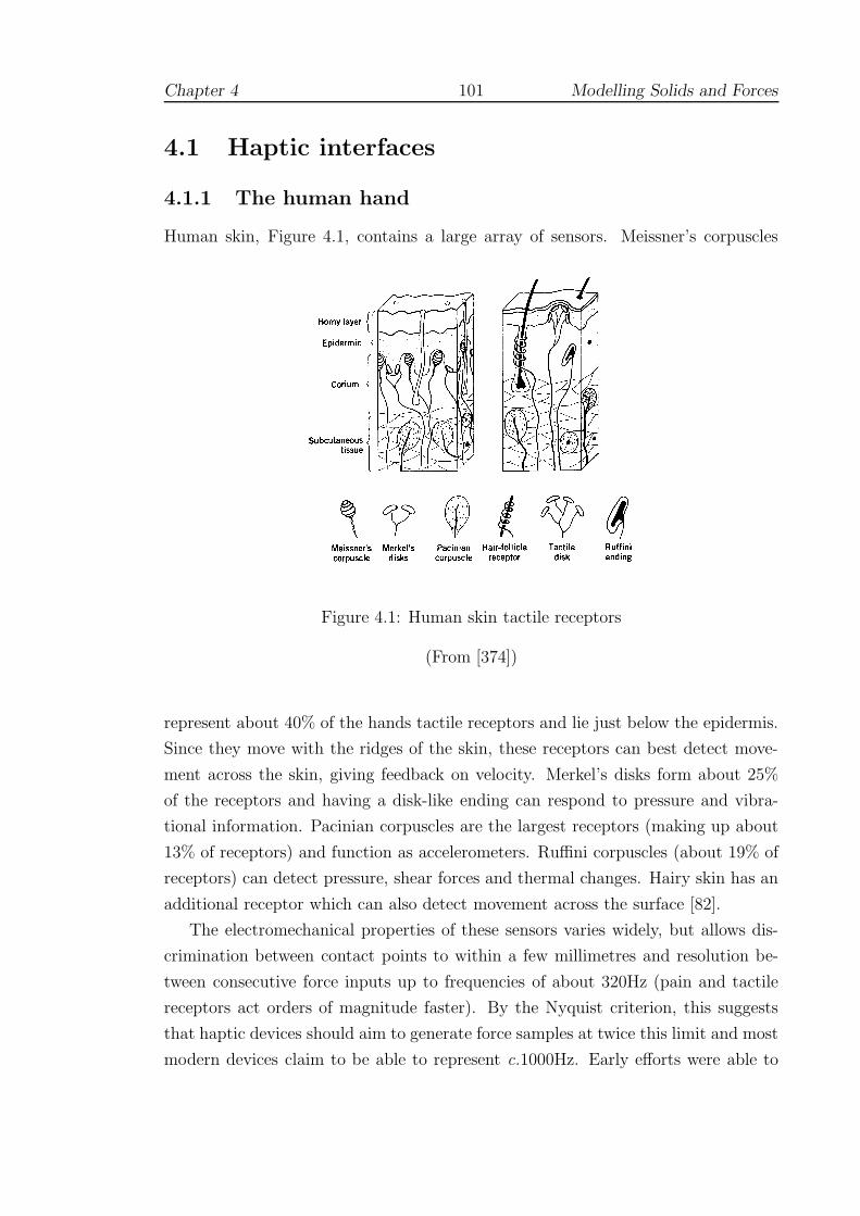
Chapter 4 101 Modelling Solids and Forces
4.1 Haptic interfaces
4.1.1 The human hand
Human skin, Figure 4.1, contains a large array of sensors. Meissner’s corpuscles
Figure 4.1: Human skin tactile receptors
(From [374])
represent about 40% of the hands tactile receptors and lie just below the epidermis.
Since they move with the ridges of the skin, these receptors can best detect move-
ment across the skin, giving feedback on velocity. Merkel’s disks form about 25%
of the receptors and having a disk-like ending can respond to pressure and vibra-
tional information. Pacinian corpuscles are the largest receptors (making up about
13% of receptors) and function as accelerometers. Ruffini corpuscles (about 19% of
receptors) can detect pressure, shear forces and thermal changes. Hairy skin has an
additional receptor which can also detect movement across the surface [82].
The electromechanical properties of these sensors varies widely, but allows dis-
crimination between contact points to within a few millimetres and resolution be-
tween consecutive force inputs up to frequencies of about 320Hz (pain and tactile
receptors act orders of magnitude faster). By the Nyquist criterion, this suggests
that haptic devices should aim to generate force samples at twice this limit and most
modern devices claim to be able to represent c.1000Hz. Early efforts were able to
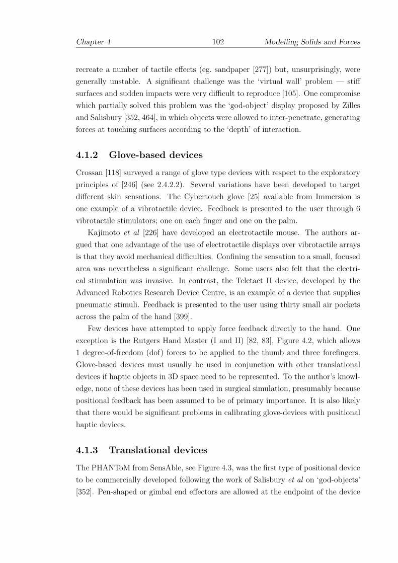
Chapter 4 102 Modelling Solids and Forces
recreate a number of tactile effects (eg. sandpaper [277]) but, unsurprisingly, were
generally unstable. A significant challenge was the ‘virtual wall’ problem — stiff
surfaces and sudden impacts were very difficult to reproduce [105]. One compromise
which partially solved this problem was the ‘god-object’ display proposed by Zilles
and Salisbury [352, 464], in which objects were allowed to inter-penetrate, generating
forces at touching surfaces according to the ‘depth’ of interaction.
4.1.2 Glove-based devices
Crossan [118] surveyed a range of glove type devices with respect to the exploratory
principles of [246] (see 2.4.2.2). Several variations have been developed to target
different skin sensations. The Cybertouch glove [25] available from Immersion is
one example of a vibrotactile device. Feedback is presented to the user through 6
vibrotactile stimulators; one on each finger and one on the palm.
Kajimoto et al [226] have developed an electrotactile mouse. The authors ar-
gued that one advantage of the use of electrotactile displays over vibrotactile arrays
is that they avoid mechanical difficulties. Confining the sensation to a small, focused
area was nevertheless a significant challenge. Some users also felt that the electri-
cal stimulation was invasive. In contrast, the Teletact II device, developed by the
Advanced Robotics Research Device Centre, is an example of a device that supplies
pneumatic stimuli. Feedback is presented to the user using thirty small air pockets
across the palm of the hand [399].
Few devices have attempted to apply force feedback directly to the hand. One
exception is the Rutgers Hand Master (I and II) [82, 83], Figure 4.2, which allows
1 degree-of-freedom (dof) forces to be applied to the thumb and three forefingers.
Glove-based devices must usually be used in conjunction with other translational
devices if haptic objects in 3D space need to be represented. To the author’s knowl-
edge, none of these devices has been used in surgical simulation, presumably because
positional feedback has been assumed to be of primary importance. It is also likely
that there would be significant problems in calibrating glove-devices with positional
haptic devices.
4.1.3 Translational devices
The PHANToM from SensAble, see Figure 4.3, was the first type of positional device
to be commercially developed following the work of Salisbury et al on ‘god-objects’
[352]. Pen-shaped or gimbal end effectors are allowed at the endpoint of the device

Chapter 4 103 Modelling Solids and Forces
Figure 4.2: Rutgers Hand Master II
(from http://www.caip.rutgers.edu)
Figure 4.3: PHANToM Desktop haptic device
(from [373])
Chapter 4 104 Modelling Solids and Forces
which has 6 dof (translational and rotational) input and 3 dof (or optionally 6
dof) force output. Hollerbach has pointed out that the workspace of these devices
is always an important issue [211]. The smaller Desktop PHANToM permits a
workspace of 160×120×120 mm, with a continuous maximum force output of 1.75N
(maximum exertable 7.9N). The larger PHANToM models permit a workspace of
900×900×300 mm and force output of 3N continuously (or 22 N maximum) which
allows calibration with virtual workbench devices [68].
Whilst the PHANToM devices might be thought to relate to activities with the
hand and forearm, the HapticMaster developed by FCS Robotics [2, 431] (Figure
4.4) accommodates arm movements within a volume of 360×400×640 mm with a
Figure 4.4: FCS Robotics HapticMASTER
(from [2])
much larger force range, up to a maximum output of 250N (100N continuously)
with a resolution of 0.01N. This device can therefore simulate more forceful lifting
or pulling activities, perhaps, most obviously, in rehabilitation tasks.
Although a pair of PHANToM devices can be used in an adjacent, overlapping
workspace (see 2.4.2.3), the SPIDAR haptic device relies upon tensioned cables
which control eight fingertip attachment devices and allows close working of both
hands, see Figure 4.5. The concept is scalable to almost any workspace and pre-
liminary evaluation of a bimanual task has demonstrated remarkable effectiveness
[238, 438]. Rotational input or output with the SPIDAR and HapticMaster de-
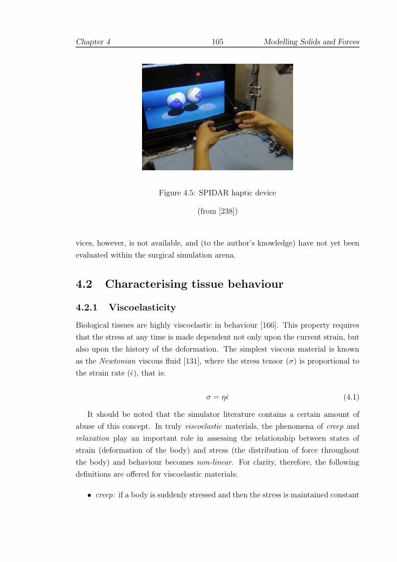
Chapter 4 105 Modelling Solids and Forces
Figure 4.5: SPIDAR haptic device
(from [238])
vices, however, is not available, and (to the author’s knowledge) have not yet been
evaluated within the surgical simulation arena.
4.2 Characterising tissue behaviour
4.2.1 Viscoelasticity
Biological tissues are highly viscoelastic in behaviour [166]. This property requires
that the stress at any time is made dependent not only upon the current strain, but
also upon the history of the deformation. The simplest viscous material is known
as the Newtonian viscous fluid [131], where the stress tensor (σ) is proportional to
the strain rate (ε), that is:
σ = ηε (4.1)
It should be noted that the simulator literature contains a certain amount of
abuse of this concept. In truly viscoelastic materials, the phenomena of creep and
relaxation play an important role in assessing the relationship between states of
strain (deformation of the body) and stress (the distribution of force throughout
the body) and behaviour becomes non-linear. For clarity, therefore, the following
definitions are offered for viscoelastic materials:
• creep: if a body is suddenly stressed and then the stress is maintained constant

Chapter 4 106 Modelling Solids and Forces
thereafter, the body continues to deform.
• relaxation: if a body is suddenly stressed and then the strain is maintained
constant thereafter, the corresponding stresses in the body decrease with time.
• non-linearity: the behaviour of linear systems is described in Chapter 6. It
will be seen that these systems can be described by the relation Ku = f , where
K is the ‘stiffness’ matrix dependent upon the composition and geometry of
the body under consideration (see Equation 6.38 for definition of these terms).
An important distinction between linear and non-linear systems is that for the
latter, K must be recalculated at each time-step, depending on the previous
history whereas K is constant for linear systems [106].
Given the demands of real-time display, it should be noted that for most simula-
tions non-linear behaviour is ignored. A few prototypical systems are nevertheless
described in Section 4.5.
4.2.2 Tissue properties
4.2.2.1 Approaches
In vascular procedures, surgical experience suggests that tissue resistance can vary
significantly, especially if vessels are diseased or calcified. In such cases, sufficient
force must be applied at an appropriate rate - or the needle cannot be properly
inserted. Some progress has been made with the application of viscoelastic models
to medical simulations, where the number of degrees-of-freedom (dof) is restricted
[467, 437, 86], but for more open applications, their use is prohibited [242].
The calibration of soft tissue models is the subject of ongoing work by numerous
researchers [164, 436], but most recently (with respect to surgical simulation) at
VESTA [27]. This work shows that the tissue stress response tends to follow a
‘J’-shaped curve, with two possible phases of linearity, see Figure 4.6. This figure
plots the reaction of in vivo porcine tissue against the Lagrangian stretch ratio, λ,
where λ = length/original length. Attempts to measure the moduli of human tissue
remotely are underway [164, 261, 402] (and see below).
Raghavan et al proposed a possible mathematical basis for the appearance of
this curve, suggesting that the two linear phases correspond to the varied reaction
of elastin and collagen fibres [327] (and see [271]). In their model, the elastin fibres
react first, but are more compliant giving rise to the shallow initial portion of the

Chapter 4 107 Modelling Solids and Forces
Figure 4.6: ‘J’-shaped tissue responses
(from [77])
strain curve. If the tissue is stretched further, the stiffer collagen fibres start to
align causing a much steeper (and tougher) response. Eventually the collagen fibres
come to dominate the response, giving rise to the second linear phase. Researchers
at VESTA have shown that the initial phase of linearity may extend up to c.15%
strain for in vivo tissues. For conditioned ex vivo tissues, this limit occurs at c.60%
strain [77].
It is apparent from these results that choosing simple models to characterise
tissue across a broad range of conditions is unlikely to give universal satisfaction.
Configuring such models with appropriate parameters adds yet another layer of
difficulty and numerous techniques for establishing these parameters both ex vivo
and in vivo have been attempted [149, 245, 261, 326, 436, 460]. Fu et al [164] have
observed that the most accurate numerical simulations of biomechanical problems
employ estimates of Young’s Modulus, E, for soft tissues in the range, E = 1 −200 kPa and for Poisson’s Ratio, ν ≥ 0.495 is usually employed. Choice of the
latter is more restricted since ν = 0.5 is the strict upper limit for incompressible
materials at which conventional linear systems become insoluble. More difficulty
arises if disease needs to be considered: Carter et al found that the right lobe of
Chapter 4 108 Modelling Solids and Forces
human liver had a mean elastic modulus of about 270 kPa — but a single case of a
diseased liver had a modulus of 740 kPa [90]. Solutions to the choice of parameters
for particular models will inevitably involve a quantity of subjective testing since
function, scale, dessication and disease will all play a role.
4.2.2.2 Assessment techniques
Many recent studies have been orientated towards the validation of relatively new
techniques of assessment, such as elastography [354]. Dimitriadis et al [137] have
attempted to address a number of problems that limit the use of the atomic force
microscope when measuring elastic moduli of soft materials at microscopic scales,
by producing error corrections and obtaining estimates for sensitivity to error. Sim-
ilarly, Nightingale et al have presented results from ongoing human in vivo and
ex vivo studies, evaluating the correlation between acoustic radiation force impulse
images and tissue pathology by use of eg. finite element models [301].
Vessel hardening has been investigated by Katakami et al [227] by employing
ultrasonic backscatter to estimate the thickness of carotid artery intima media.
Ebenstein et al [141] have described another force technique, using nanoindenta-
tion, which showed that repair tissue of rabbits possessed a much reduced modu-
lus, despite being histologically comparable to undamaged tissue. In vivo human
measurements have also been obtained by Herrington et al who used a computer-
controlled air plethysmograph (in conjunction with MRI data) to identify the onset
of atherosclerosis by estimating blood volume in the leg [204].
4.2.2.3 Validation of tissue parameters
The validation of particular tissue parameters for use in haptic simulations remains
a relatively new field (but see 2.4.2.3). However, a study undertaken by Sur et al
[404] found that a small group of registrars were reasonably sensitive to changes
in Young’s modulus (of c.1kPa) and Poisson’s ratio (of c.0.02). But although most
participants selected acceptable values for tissue parameters (when asked to choose),
opinion was observed to vary quite widely as to what felt most ‘realistic.’ Further
attempts to validate particular models are described in Sections 4.3.3.4 and 4.3.4.6.
An interesting approach which is still being developed is that of the ‘truth cube.’
Kerdok et al [231] took CT images of a cube of silicone rubber embedded with a
regular array of Teflon spheres, which underwent various uniaxial compression and
spherical indentation tests. This resulted in a complete set of volumetric displace-
Chapter 4 109 Modelling Solids and Forces
ment data which were contrasted to a finite element model using the same material
properties, geometry and controlled boundary conditions. The data are offered as
a ‘proof of concept’ for physical standards in validating soft tissue models and have
been made available on the web (http://biorobotics.harvard. edu/truthcube). Fu-
ture work is intended to develop a liver model.
4.2.3 Tissue response in surgical procedures
4.2.3.1 Force analysis
In parallel with attempts to characterise tissue in standard laboratory tests (ie. in
vitro), several groups have attempted to investigate the forces and deformations
involved with particular surgical procedures. For example, Azar et al have used a
non-linear Mooney-Rivlin FEM to predict the position of possible tumours during
breast biopsy [43]. Similarly, after Bholat et al [60] established that force-feedback
was important for some laparoscopic procedures, other researchers have attempted
to model the subtle forces involved [86, 311, 337].
Kitagawa et al [236] have analysed forces used in knot-tying in comparison with
a telerobotic device. Interestingly, a test between novices and experts revealed that
forces used during hand ties were significantly different between the groups (direction
not given), but that these differences were lost when using robotic assistance.
4.2.3.2 Puncture analysis
Several attempts have been made to characterise the response of skin and muscle
to puncture by needles. Brett et al [70] used a tensile testing machine to map the
resistance force to hollow spinal needle placement during lumbar puncture. Higher
needle velocities were found to result in lower peak forces encountered during the
puncture of ligament. Ankersen et al [38] observed that skin is composed of two
main layers: the outer epidermis and inner dermis. Most of the material strength of
skin is provided by the dermis, which is made up of densely packed collagen fibres
at random orientations, elastin fibres and a ground substance. This dual-layered
structure causes skin to be supple at low strain but to exhibit considerable stiffness
at higher strains. Despite this, the influence of the two distinct layers was not visible
in the data of either the Brett or Ankersen studies.
More recently, however, Frick et al [161] were able to observe two peaks in the
puncture data corresponding to the piercing of each layer in turn, Figure 4.7. In
their study, samples of ovine skin and tendon material were pierced with straight

Chapter 4 110 Modelling Solids and Forces
Figure 4.7: Load vs displacement of ovine skin
(from Frick et al [161])
suture needles under three different states of tension and with three different needle
velocities (1, 5, and 10 mm/s). In contrast to Brett et al, no variance of tissue
stiffness (the gradient of the graph in the figure) was found with needle velocity,
albeit the statistical power of this test was low (0.1 < β < 0.5). The various
states of tension were intended to mimic the action of surgeons steadying tissue
prior to needle insertion; two surgeons were asked to provide an initial estimate of
appropriate forces and the experiment was designed around these values. Tissue
stiffness was found to vary significantly with respect to tensioning of the tissue prior
to puncture, indicating that by increasing the level of control placed upon the tissue,
a greater insertion force was required. In conclusion the authors noted that their
study was: ‘limited in that only one needle design, two sheep tissue types and three
test displacement rates and tissue tensions were used. Results may differ with other
needle displacement rates, designs and tissue types.’
4.2.3.3 Modelling approaches
It is convenient at this point to give a brief description of recent attempts to assim-
ilate this behaviour into mathematical models for simulation. Direct measurement
of needle forces is a challenging problem since soft tissues may both deform and
move. DiMaio et al [136] have used the results of robotic testing, using an epidu-
ral needle with a tissue phantom (E = 34 kPa, ν = 0.34), to obtain estimates of

Chapter 4 111 Modelling Solids and Forces
the force distribution along the length of the needle during insertion. This allowed
an improved model of insertion to be developed as the impact on the mesh was
more controlled and regions of very high strain (which tended to exceed linear finite
element capabilities) were avoided.
Alterovitz et al [35] observed that this model achieves fast update rates and
high levels of accuracy, but requires a calibration phase which would be difficult to
perform in vivo. An alternative model was therefore proposed, which was based on
a reduced set of scalar parameters such as needle friction, sharpness and velocity.
Using a nonlinear 2D finite element model, the authors found that a reasonable
approximation to tissue behaviour could be obtained by considering the procedure
(brachytherapy) as comprising seven phases of force interaction, eg. membrane punc-
ture, insertion, tissue settling etc. The resulting simulation was capable of 24 frames
per second rate using a 1250 triangular element mesh and therefore gave a usable
real-time graphical representation.
A number of force display models have been recently developed. Okamura et al
[306] proposed a 3-stage model, combining an initial nonlinear spring model, a mod-
ified Karnopp friction model and a constant cutting resistance for a given tissue.
Data on needle diameter and tip type were also obtained using a silicone rubber
phantom. However, a more dynamic friction model has been developed by Zhang
and Phillips [461] to avoid the issue of criteria selection and the problems this creates
when simulations approach these values. With the ultimate objective of validating
such models, Healey et al [202] have obtained data from interventional radiological
procedures, both in vitro and in vivo, by using non-intrusive finger-mounted force
sensor pads. These data were calibrated against puncture force measurement ap-
paratus. Although force, rather than pressure effects, were isolated, it was not yet
possible to distinguish cutting from friction or damping effects. Interestingly, the
patient’s pulse created an additional level of ‘noise’ and it was suggested that this
might be used to add or test realism in future simulators.
4.3 Deformable modelling in real-time
4.3.1 Overview
Deformable modelling for tissue simulation has shown three main axes of develop-
ment, Figure 4.8. These axes can be described as:
1. Non-physical, including web-based systems with compositing or ‘chainmail’

Chapter 4 112 Modelling Solids and Forces
eg. FEM, BEM, LEM
Non − physical (inexpensive and scalable)
Physical (using material properties)
Particle − based (topologically variable)
eg. FFD, Chainmail
eg. Mass − spring models
Figure 4.8: Axes of modelling development
algorithms: deformation characteristics are accumulated across the volume
using, say, volume or greyscale intensity to estimate likely responses.
2. Particle-based, using mass-spring-damper (MSD) components to represent a
continuous mesh structure. This model may be physically sophisticated, but in
representing specific materials or tissues, the choice of parameters is arbitrary.
3. Physical, such as FEM, which uses continuous functions to represent known
material properties.
In practice, simulations may use a mixture of models, depending of the requirements
of the given task or sub-task (see 2.4.2.3). The development and orientation of these
models along the suggested axes is discussed below.
4.3.2 Non-physical models
4.3.2.1 Free-form deformations
The earliest attempts to generate real-time (graphical) frame rates with deformable
models used the surface-based geometric forms, the animation of which was achieved
by manipulating the nodes of the mesh or outlying control points [371, 416]. Whilst
these models were straightforward to implement in real-time, the absence of internal
Chapter 4 113 Modelling Solids and Forces
properties meant that it was difficult to create realistic deformations to simulate
interaction. In other words, the simplicity of these models was offset by the skill
required by designers to animate the meshes. Cover et al, for example, developed a
laparoscopic simulation of a gall-bladder combining free-form deformations (FFDs)
with energy-minimising ‘snakes’ to represent the impact of the procedure. These
models could be convincing, although lattice violations and 3D aliasing were still
common [114, 249].
Following improvements to the FFD algorithm to allow better volume preserva-
tion characteristics [207] and more intuitive methods of mesh manipulation [214],
interest in the free-form approach has recently been revived. Several commercial
‘low-cost’ procedural simulators have been developed eg. by [?], including laparo-
scopic, catheterisation and suturing devices.
4.3.2.2 Volumetric approaches
Besides reducing objects to their surface geometry, another promising approach was
to build simple 3D meshes (eg. of cubes) over which given properties could be accu-
mulated. Avila and Sobierajski [42] created a voxel-based model which used image
intensities (and intensity gradients) to propagate stiffness factors across the mesh.
Forces could then be generated to allow the haptic exploration of visualization ab-
stractions such as isosurfaces.
In developing the ‘chainmail’ algorithm, Gibson et al [175, 176] realized that
deformation information could also be propagated efficiently across the volume, Fig-
ure 4.9. The low computational overhead of this scheme readily allows topological
changes (eg. cutting) to be simulated and the method has proved sufficiently durable
that various extensions have been established, such as: (i) a relaxation step, to pro-
vide a method of calculating force feedback [174, 162]; (ii) use of non-uniform grids
and tetrahedral meshes [253] (see Figure 4.10) ; and (iii), accommodation within
web-based simulations [254].
Although web-based applications achieve versatility through their availability
and scalability, haptic feedback in this environment is not yet feasible [75, 222]. A
prototypical arthroscopic haptic simulator using a PHANToM device was demon-
strated in [174], which used a voxel-based method similar to that of Avila and
Sobierajski (ibid) to generate force data from images of MRI data. Nevertheless,
more direct methods of generating force-feedback are currently being investigated
[98], with creeping, hysteresis and non-linear responses also being modelled [97].

Chapter 4 114 Modelling Solids and Forces
Figure 4.9: 2D Chainmail operation
In 2D, the Chainmail algorithm acts so that when one link of the 2D object ismoved along the path of the arrow (a), its neighbouring links move to satisfymaximum and minimum distance requirements between elements (b) [174].
Figure 4.10: Generalised chainmail
(from [253])

Chapter 4 115 Modelling Solids and Forces
4.3.3 Particle-based models
4.3.3.1 The underlying physical basis
This approach to modelling might best be described as ‘quasi-physical’: although
the underlying mathematics has a basis in classical physics, it does not aim to
represent material properties directly. Instead, deformable bodies are approximated
by a collection of point masses connected by weightless springs, which are usually
damped to control vibration. Real-time computation and topological changes are
easily achieved for relatively large models, although subjective testing and an initial
processing step is usually required to optimise the choice of parameters [325, 212].
The success of mass-spring systems is governed by [131]:
• Topological design: since springs are used to constrain the distance between
two vertices, the number of springs per vertex conditions the global behaviour
of the system. If the system is under-constrained, several rest positions are
possible and the system can fall into unwanted local minima. If the system is
over-constrained, the range of deformation is restricted.
• Validity of deformations: mass-spring models are not based upon continuum
mechanics and cannot model deformations accurately beyond a very limited
capacity. For small deformations, a spring model behaves similar to a lin-
ear elastic finite element model as verified by Keeve et al [229], but the two
methods cannot otherwise be easily compared.
• Dynamic behaviour: for dynamic spring models (see 4.3.4.2 for a mathematical
definition), there is a critical stiffness above which the numerical system is
divergent (insoluble). This is also true for explicit linear FEM, but in practice,
greater timesteps appear to be possible with the latter. This suggests that
the range of possible dynamic behaviours is more restricted with mass-spring
models (eg. they must be softer).
Deussen et al [135] used simulated annealing to search for optimal parameters. An-
other approach, favoured by Radetzky et al [324], has been to obtain expert input
assisted by a fuzzy-logic procedure. This used natural language so that eg. ‘consis-
tency’ was defined by the terms: solid, hard, soft, wobbly, doughy, mushy. Despite
these drawbacks, numerous commercial systems (eg. [74, 243, 307]) and research
prototypes (eg. [145, 193, 192]) have been developed using these models.

Chapter 4 116 Modelling Solids and Forces
4.3.3.2 An example MSD algorithm
Brown et al [80] have offered the following description of their dynamic MSD al-
gorithm. The geometry of a deformable object is represented by a 3D mesh M of
n nodes Ni (i = 1, . . . , n), connected by links Lij, i, j ∈ [1, n] , i 6= j. Each node
maps to a specific point of the object, so that the displacements of the nodes de-
scribe the deformation of the object. The nodes and links on the object’s surface are
triangulated, whereas the other nodes and links are unrestricted, though it is often
convenient to arrange them in a tetrahedral lattice. The mechanical properties of
the object are described by data stored in the nodes and links of M . A mass mi
and a damping coefficient ci are associated with each node Ni, and a stiffness ki is
associated with each link Lij. The internal force between two nodes Ni and Nj is
Fij = −kij∆ijuij, where ∆ij = lij − rij is the current length of the link minus its
resting length, and uij is the unit vector from Ni to Nj. The stiffness kij may be
a constant or a function of ∆ij. In either case, Fij is a function of the coordinate
vectors xi and xj of Ni and Nj. At any time t, the motion/deformation of M is
described by a system of n differential equations, each expressing the motion of a
node Ni:
miai + civi +∑
j∈σ(i)
Fij (xi,xj) = mig + F exti (4.2)
where xi is the coordinate vector of Ni, ai and vi are the acceleration and velocity
vectors respectively, mig is the weight of each node and F exti is the total external
force applied to Ni. σ (i) denotes the set of indices of the nodes adjacent (connected
by a link) to Ni in M .
Dynamic and quasi-static versions of this algorithm were developed. The dy-
namic model uses classical numerical integration techniques such as fourth order
Runge–Kutta to solve Equation 4.2. For the quasi-static system, which was said to
give reasonable performance in most simulations, the dynamic inertial and damping
forces are ignored and the shape of M is defined by a system of equations expressing
that each non-control node Ni lies in static equilibrium, according to:
∑
j∈σ(i)
Fij (xi,xj) − mig = 0 (4.3)
Solving the system by the quasi-static (QSS) algorithm essentially has 2 steps.
In the first step, residual force components are accumulated for each node using the
left-hand side of the expression in Equation 4.3. In the second step, a conjugate
Chapter 4 117 Modelling Solids and Forces
gradient type method is used to adjust xi according to the force accumulated in
step 1. In their evaluation of QSS, using a fixed number of iterations for step 2,
the authors noted that in models of 8000 nodes, the error was consistently held at
about 10% of the magnitude of the displacement of the control node for all mesh
sizes. Errors with this algorithm for topological changes were not evaluated.
It should be noted that the relation 4.2 does not describe viscoelastic behaviour
as several authors, including Brown et al (see also [324]), appear to suggest — see
Section 4.2.1. Non-linear behaviour can nevertheless be incorporated within an MSD
framework, although computation for real-time (especially haptic) display is as not
yet possible [243]. To give a corresponding viscoelastic form, it would be necessary
to recalculate the spring constants at each time step, ie. kij would become kij (t)
and then re-integrate Equation 4.2 for each different value.
4.3.3.3 Suture and knot-tying
Several groups have used mass-spring based spline models to represent suture thread,
though none of these have been integrated into full surgical simulation. LeDuc et
al [247] explored several key principles for inserting and pulling thread through
tissue. Their solution required the use of ‘home springs’ to return the mesh to its
original topology and multiple velocity constraints to simulate the effects of friction.
Lenoir et al [251], however, have modelled friction directly using constraints given
by Lagrange multipliers and a two-stage integration process. Phillips et al [314]
have also used splines to simulate knot-tying. Stability of the mesh was found to be
improved by using Stoermer’s approximation for the second integral and hysteresis-
like threshold to add or delete control points to conserve momentum (and to allow a
simple node-based method of collision detection). This study appears to show that
realistic knots can be stable within a VR environment without the need for complex
friction models.
Mass-spring models are the basis for a number of laparoscopic suturing models,
previously discussed in Section 2.3.2.
4.3.3.4 Recent research
Maciel et al [264] have proposed various generic methods of obtaining spring con-
stants in order that stable MSD systems can be constructed, sufficient to represent
soft tissues and bone (which may be highly anisotropic). The best results were
obtained by using an iterative method to determine the spring configuration, al-
Chapter 4 118 Modelling Solids and Forces
though this was not always satisfactory. In particular, this method required that
moduli were tested in a preset direction and even then was occasionally unstable.
Mosegaard, however, has suggested that optimal parameters will be found when
models behave ‘most alike.’ An evolutionary algorithm was proposed, in which the
fitness of the mesh was assessed by evaluating the extension of the springs compared
with a reference model during the period required for the mesh to return to equi-
librium. A static finite element model was chosen as the reference which, although
slower, always returned to its undisturbed state. Mass-spring systems, on the other
hand, reacted considerably faster but did not reach absolute equilibrium [288].
Mosegaard and Mosegaard et al [287, 289] have also attempted to build a cardiac
simulation, comprising many thousands of nodes, suitable for pre-operative planning
(without haptics). The initial proposal adapted the LR algorithm of Brown et al
[79] and the relaxation technique of Casson and Laughier [91] to cope with a 35000
node model developed from MRI data, at least in the area local to tool interactions.
More recently, however, the authors have found a considerable speed-up of processing
time by transferring the problem to the graphics processing unit (GPU) of an nVidia
graphics chip ie. by adopting a hardware-based solution. The initial obstacle to this
conversion was the translation from 3D model to 2D textures, but having resolved
this the authors have found a 30-fold decrease in solution times for models of up to
105 nodes.
A further interesting development is the development of 3D warping techniques
combined with depth-mapping to overlay mass-spring models with photo-realistic
images [146, 147], see Figure 4.11.
4.3.4 FEM
4.3.4.1 Background
Finite element models describe a given shape as a set of basic elements (triangles,
tetrahedra, cubes etc.) where shape functions with limited support (‘region of in-
fluence’) are defined. This leads to continuous representations with varying levels
of continuity [131]. In solid mechanics, this mesh is used to provide ‘elements’ upon
which the elastic material functions of stress and strain are integrated. This re-
quires considerable computation, which for many engineering applications is usually
important, but not critical. In comparison with mass-spring systems, the method
gives a much clearer representation of tissue parameters to assess forces and damage
and the accuracy of the model can much more readily be upgraded by increasing

Chapter 4 119 Modelling Solids and Forces
Figure 4.11: 3D Warping technique of ElHelw et al [147]
the number of elements. Furthermore, the technique is readily extended to more
complex models of tissue behaviour such as anisotropy [315].
4.3.4.2 Mathematical basis
A mathematical basis for linear tetrahedral finite elements using the principle of
virtual work is developed in Chapter 6, but the general governing equation can be
stated as:
M u + Du + Ku = f (4.4)
where u is the displacement vector, f is a vector of forces/boundary conditions and
M , D and K are (respectively) mass, damping and stiffness coefficient matrices.
For dynamic systems, where M and D are non-zero, a major difficulty consists
of ensuring synchronicity, ie. that the numerical time used for computation matches
the user’s time for interaction. When calculating the velocity of vertices, for in-
stance, we need to know the time interval very precisely to divide the difference in
displacements at the current and previous timesteps (these quantities may be very
small so that errors are magnified). Static equations, where Equation 4.4 is reduced
to Ku = f , cannot be used to model inertia or viscoelastic properties, but have two
computational advantages [131]:
• They are faster to compute since no time integration step is needed.

Chapter 4 120 Modelling Solids and Forces
• They are well-suited to parallel or asynchronous algorithms. Cotin et al [111],
for example, used a static formulation of motion which allowed the decoupling
of force and deformation computations.
4.3.4.3 Early applications (not real-time)
In 1994, Sagar et al [351] developed a virtual environment for eye surgery simulation
where the cornea deformation was modelled as a non-linear elastic (Mooney-Rivlin)
material. The finite element solver computed the cornea deformation every second
while the graphics module was able to provide a 10Hz refresh rate, which was unique
at that time. Another typical early application of FEM to surgical problems was
that of Keeve et al [229] who, in 1996, used the method to predict the outcome of
facial surgery. These simulations could be computed very quickly (in the order of a
few minutes), but were not intended to run in real time.
4.3.4.4 Real-time approaches
The emphasis of much FEM research in this field is upon finding faster solutions.
Shiakolas [385], for example, proposed a closed form method of computing stiffness
matrices although this method has not been adopted in simulations as far as the au-
thor is aware. Condensation and Banded-matrix methods developed (respectively)
by Bro-Nielson et al [71] and Berkley et al [58] use matrix manipulations to re-
move the need to compute the influence of internal nodes (see discussion in Section
6.3.2). This meant that real-time solutions became possible albeit substantial pre-
processing steps were then required. The need for significant pre-computation was
a limiting factor, however, since this prevented further topological changes of the
mesh, such as might be required to represent tearing, cutting or piercing.
Cotin et al [112] presented a more radical solution, the tensor-mass model, using
an extensive pre-computation step compiling tensors to define standard displacement
fields at each movable node in the mesh. This work was based on the principle that
linear static elements define regions of constant strain and since elastic energy may
be expressed as a quadratic function of displacement, the force at each node can be
defined as a linear function of displacement. Using a conjugate gradient solver and
a restricted collision detection algorithm (see 4.6.3), the tensors and mesh can be
updated dynamically, allowing topological changes (such as cutting) for meshes of
760 nodes with updates at 40Hz (on 233MHz PC) in a hepatic (liver) simulation.
Also, with super-imposed solutions, non-linear models could also be approximated
Chapter 4 121 Modelling Solids and Forces
[113]. More refined algorithms for achieving cutting/tearing are discussed below
(4.3.4.5).
Ignoring cutting operations, several FEM implementations using matrix factori-
sation have been shown to be feasible:-
• James and Pai [219] have produced interactive linear elastic simulations by us-
ing boundary integral formulations (ie. Boundary Element Method or BEM )
for graphical character animation. The authors point out that BEM produces
smaller, more compact linear systems which are therefore easier to solve; also,
BEM is more accurate for computing contact forces than the FEM since forces
are solved for just like displacements, instead of being derived from displace-
ments using difference formulas. But since the influence of internal structures
is ignored, only homogeneous materials may be considered ie. variations due to
anatomy or disease cannot be modelled. Also, as the technique is best suited
to rounded objects, haptic interaction with more realistic human anatomical
models has yet to be achieved [459] (and see [279]).
• The method adopted by James and Pai in the above is an algebraic procedure
which is more or less equivalent to computing a matrix inverse [131]. James
and Pai have, however, extended the technique to solve linear elastostatic sys-
tems by using pre-computed Green’s functions (GF) and fast low-rank updates
based on capacitance matrix algorithms [220]. The matrices constitute exact
force response models, allowing contact forces to be computed much faster
than global deformation behaviour. It is also possible to decouple the global
deformation calculation from that of the local force response, so that for haptic
displays, the local contact response may be computed at a much faster rate
than the global deformation. The authors have demonstrated satisfactory hap-
tic performance for modest models (<1000 nodes) using Java3D and a native
interface to the GHOST API [373]. Collision detection, however, was limited
to a single contact point on the undeformed object. A similar approach has
also been adopted by Nikitin et al [302].
• Zhuang and Canny [463] observed that linear strain does not model finite
rotation correctly, and introduces distortions when large global deformations
occur. Employing quadratic strain terms avoids this problem, but the authors
found that implicit integration in real-time was impossible for meshes of any
size (implicit schemes tend to have better convergence properties). However,
by lumping the rows of mass matrix, M , into a diagonal form and adopting
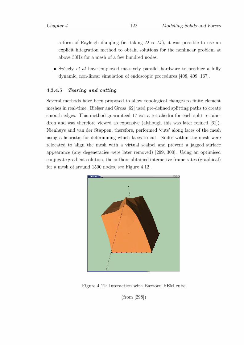
Chapter 4 122 Modelling Solids and Forces
a form of Rayleigh damping (ie. taking D ∝ M), it was possible to use an
explicit integration method to obtain solutions for the nonlinear problem at
above 30Hz for a mesh of a few hundred nodes.
• Szekely et al have employed massively parallel hardware to produce a fully
dynamic, non-linear simulation of endoscopic procedures [408, 409, 167].
4.3.4.5 Tearing and cutting
Several methods have been proposed to allow topological changes to finite element
meshes in real-time. Bielser and Gross [62] used pre-defined splitting paths to create
smooth edges. This method guaranteed 17 extra tetrahedra for each split tetrahe-
dron and was therefore viewed as expensive (although this was later refined [61]).
Nienhuys and van der Stappen, therefore, performed ‘cuts’ along faces of the mesh
using a heuristic for determining which faces to cut. Nodes within the mesh were
relocated to align the mesh with a virtual scalpel and prevent a jagged surface
appearance (any degeneracies were later removed) [299, 300]. Using an optimised
conjugate gradient solution, the authors obtained interactive frame rates (graphical)
for a mesh of around 1500 nodes, see Figure 4.12 .
Figure 4.12: Interaction with Bazzoen FEM cube
(from [298])

Chapter 4 123 Modelling Solids and Forces
In future, the answer may lie in the realm of so-called meshless methods. De et
al [129, 128] have suggested that ordinary meshes should be abandoned in favour of
a more localised systems of ‘spheres’, in effect allowing a locally refined mesh to be
quickly constructed at the point of contact. Another suggestion is that by Vigneron
et al [434]. By incorporating discontinuous functions into the standard FEM, the
Extended FEM can be used to model incisions, without the need for remeshing. The
choice of these functions was explored by the authors and a successful simulation
was created using simple 2D objects (rectangles and ellipses).
However, a more immediate solution may be the use of multi-resolution, or hier-
archical, meshes. In most simulations, the effects of tool interactions are relatively
local to the point of contact, so it is generally safe to ignore the displacement of dis-
tant nodes. In the research by Faraci et al [152], contact results in the selection of
tetrahedral nodes nearest the contact point (‘level 1’), then those of the tetrahedra
associated with these nodes (‘level 2’) and so on. Using a level 2 mesh, Rayleigh
mass-lumping and pre-computed element volumes etc., the finite element equations
may be set up and solved using a central differences scheme in real-time. This
method is fully dynamic in that different parts of the mesh may be selected at each
tool contact. Using a liver model with 1500 nodes, the authors were able to investi-
gate the choice of various damping parameters and constraints for use with haptic
simulation. The authors have also incorporated non-linear behaviour and mesh re-
finement (to increase stability) for meshes of the order of 102 nodes [153]. A hybrid
multi-resolution model, capable of haptic update rates, has also been advanced by
Frisoli et al [163].
4.3.4.6 Recent research
Zhong et al [462] have proposed an extension of the tensor mass model of Cotin et al
[112] by pre-computing the matrix inverse and condensing to remove fixed boundary
nodes. Whereas the former method requires that the FEM solver execute 3k times
(where k the number of contact nodes), using the inverse allows the generation of
tensor components directly. The authors have also described algorithms to introduce
a polynomial interpolation of non-linear behaviour and an affine mapping of contact
regions using St Venants Principle. A graphical simulation incorporating these ideas
has been developed which allows limited interaction of brain tissue.
Kuroda et al have attempted to model interactions between multiple soft objects
of different elastic properties [244]. This problem creates particular difficulties for
collision detection algorithms, since the collision mesh must also be updated (see
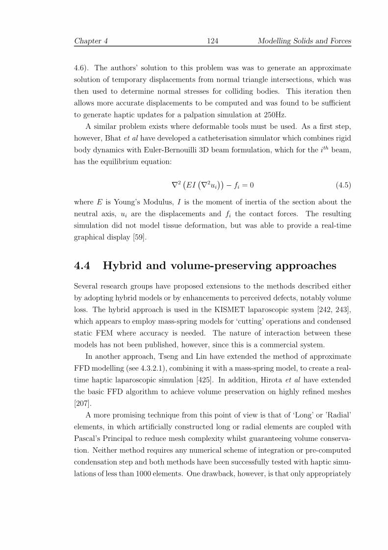
Chapter 4 124 Modelling Solids and Forces
4.6). The authors’ solution to this problem was was to generate an approximate
solution of temporary displacements from normal triangle intersections, which was
then used to determine normal stresses for colliding bodies. This iteration then
allows more accurate displacements to be computed and was found to be sufficient
to generate haptic updates for a palpation simulation at 250Hz.
A similar problem exists where deformable tools must be used. As a first step,
however, Bhat et al have developed a catheterisation simulator which combines rigid
body dynamics with Euler-Bernouilli 3D beam formulation, which for the ith beam,
has the equilibrium equation:
∇2(
EI(
∇2ui
))
− fi = 0 (4.5)
where E is Young’s Modulus, I is the moment of inertia of the section about the
neutral axis, ui are the displacements and fi the contact forces. The resulting
simulation did not model tissue deformation, but was able to provide a real-time
graphical display [59].
4.4 Hybrid and volume-preserving approaches
Several research groups have proposed extensions to the methods described either
by adopting hybrid models or by enhancements to perceived defects, notably volume
loss. The hybrid approach is used in the KISMET laparoscopic system [242, 243],
which appears to employ mass-spring models for ‘cutting’ operations and condensed
static FEM where accuracy is needed. The nature of interaction between these
models has not been published, however, since this is a commercial system.
In another approach, Tseng and Lin have extended the method of approximate
FFD modelling (see 4.3.2.1), combining it with a mass-spring model, to create a real-
time haptic laparoscopic simulation [425]. In addition, Hirota et al have extended
the basic FFD algorithm to achieve volume preservation on highly refined meshes
[207].
A more promising technique from this point of view is that of ‘Long’ or ’Radial’
elements, in which artificially constructed long or radial elements are coupled with
Pascal’s Principal to reduce mesh complexity whilst guaranteeing volume conserva-
tion. Neither method requires any numerical scheme of integration or pre-computed
condensation step and both methods have been successfully tested with haptic simu-
lations of less than 1000 elements. One drawback, however, is that only appropriately

Chapter 4 125 Modelling Solids and Forces
shaped objects can be modelled [110, 46].
4.5 Viscoelastic simulations
A number of researchers have attempted produce more realistic tissue deformation
by use of non-linear techniques either with purely graphical displays or with limited
haptic interaction. Scilingo et al employed Hertz theory based on solids of revolution
to create a non-linear response which was rendered by a 1D pneumatic haptic device
[365]. Cai et al [86] employed an implicit Euler integration scheme in conjunction
with a linear viscoelastic Voigt dashpot to generate non-linear behaviour for a small
plate of c.500 nodes. This was linked to 2D haptic and graphical display and was
capable of updates at 25 Hz (on a 450MHz PC).
Schill et al have extended the chainmail algorithm (see 4.3.2.2) to accommodate
the behaviour of inhomogeneous materials [360]. The Enhanced 3D Chainmail algo-
rithm works by processing the elements in the object so that the deformation travels
most quickly through stiff materials. The intended application for this technique was
to simulate a vitrectomy procedure (the removal of blood, debris etc. from the eye)
but this does not seem to have been followed up. Later, however, Frisken-Gibson
[162] was able to show that the method could be adapted to allow a relaxation step
in which hysteresis-like behaviour could be incorporated. Hysteresis and creep were
introduced into the model by Choi et al [98] which combined a force propagation
approach with a mass-spring based mesh.
Mahvash and Haywood observed many researchers in this area ([86, 456] etc.)
had essentially simplified either FEM or the contact problem to make the high rate
computation of forces possible [268]. To address this, the authors developed an ap-
proach based on the book-keeping of force deflections curves stored at the nodes of
a triangulated body surface. Using a virtual environment which comprised a tool
interacting with a deformable cylindrical virtual body made of about 500 ‘patches’,
their tests showed that coordinates interpolation, together with force-deflection in-
terpolation provided continuity for the responses. The forces were generated by a
PenCat/ProTM haptic device (Immersion Inc. [25]) which is ‘direct drive’ and hence
provides good fidelity because of near absence of mechanical damping.
Chapter 4 126 Modelling Solids and Forces
4.6 Collision detection
4.6.1 Background
Efficient collision detection has been the subject of a great deal of research over
the past decade and many libraries have now been released into the public domain
eg. VCollide [215], V-Clip [278]. Several groups have developed techniques specifi-
cally for rigid body haptic interaction. Koenig et al used coherence [239] to optimise
the collision search. Gregory et al used tightly defined bounding boxes in HCollide
[256]. None of these algorithms are capable of handling deformable models. For
researchers working in this area, three possible avenues would seem to be open:
(i) to update bounding boxes after deformations occur; (ii) to employ hardware-
based optimisations; and (iii) to use a local collision detection scheme, with specific
simplifications depending on the task.
At the time of writing, it is not possible to obtain a collision detection library
which supports deformable models, either commercially or in the public domain1.
As a result, many surgical simulations have developed in-house systems (ie. a local
methods) eg. KISMET, BDI etc. The remaining options are explored briefly below.
4.6.2 Bounding-box techniques
van den Bergen has adapted the algorithm of Gilbert, Johnson and Keerthi (GJK),
which essentially provides a simple, efficient method for finding the minimum dis-
tance between two convex objects [430, 177]. Axis-aligned bounding boxes were
shown to be more efficient for handling dynamic and deformable models than arbi-
trarily oriented systems [429].
In [80], Brown et al pointed out that this scheme tended to produce an unbal-
anced tree hierarchy which was potentially more costly in terms of collision detection
queries, and, more seriously, was unable to exploit the localised nature of most de-
formations. Instead, the latter favoured a sphere-based bounding box scheme (based
on Quinlan’s algorithm [322]) in which spheres of a set radius were allocated to each
triangle in the mesh and a hierarchy of larger spheres defined the collision search
path. This scheme has yet to be integrated into a full simulation, but the authors
estimated that maintenance of the sphere-based collision tree required 0.06 ms per
deformed triangle. Ganovelli et al have advocated a more flexible approach to the
1SOLID [429] includes an appropriate API, but does not yet function correctly: see Section5.3.6.

Chapter 4 127 Modelling Solids and Forces
choice of bounding volume by using a selection step to optimise this choice [171].
4.6.3 Hardware solutions
The ‘bucket’ data structure created by Cotin et al (see 4.3.4.4) allowed effective
allocation of surface triangles into separate bins but did not permit updates to the
bucket data structure when running. But even if real-time updates were allowed,
schemes of this type are scarcely adequate where large deformations and topological
changes can — and often do — occur: time spent pre-computing complex bounding
volumes appears to be fruitless. Also, since complex anatomical objects usually
remain in close juxtaposition, collisions can be frequent and numerous.
Fortunately, the tools themselves can usually be modelled by simple shapes and
their motion is quite restricted (at least in laparoscopic procedures), so that there is
little difficulty in simulating the required workspace in modern, hardware-accelerated
displays. For Lombardo et al [260], the pruning of distant triangles from the display
frustum, and the availability of these routines through OpenGL, suggested a mech-
anism by which dynamic collision could be implemented. In particular, the authors
found that by defining additional view volumes around these tools, it was possible
to make OpenGL calls to obtain a list of nearby triangles. The view volumes could
also be distorted to cover the region of movement around each tool over a given
timestep. In addition to coping with deformable models, the scheme was at least 5
times faster for rigid body interactions than, for example, RAPID [14].
Hardware-based approaches using multi-pass rendering techniques to generate
proximity queries have also been proposed by Hoff et al [208] with optimisations (by
making direct calls to the graphics processing unit) by Govinderaju et al [185].
4.7 Applications to suturing
4.7.1 Overview
This section briefly reviews published modelling approaches of several prototype
suturing simulators — the reader is referred to Section 2.4.3 for a discussion of the
validation of these systems.

Chapter 4 128 Modelling Solids and Forces
4.7.2 BDI anastomosis simulator
The BDI simulator modelled two tube-like structures comprising around 1200 poly-
gons which were displayed through OpenGL accelerated hardware on a Silicon
Graphics Maximum Impact Indigo 2 workstation. A lumped-mass model was used to
model the ‘free’ vessel and an elastic spine was used to model bending, stretching and
local deformations [318]. The physical properties of the tube, such as compliance,
were set after discussion with a number of physicians. A simple damped mass-spring
model (based on penalty-method techniques) was used to calculate forces, displayed
using PHANToM devices from SensAble [373]. Collision detection was adapted from
the method of Lin and Canny [255]: polyhedra were stored in memory as a series of
depth values and compared with the ‘depth’ of the tool contact point.
The metrics used for validation are described in Section 2.4.3.3.
4.7.3 Penn State University/Millersville prototype
Webster et al [444] (see also Haluck et al [192]) have developed a haptic simulation
designed to teach basic suturing for simple wound closure. A damped 2D mass-
spring mesh (overlain by a wound texture) was employed to provide the underlying
force model, see Figure 4.13 . Deformation computations were undertaken by using
an implicit solver and speeded up for real-time use by using the pre-computational
approximation method of Desbrun et al [134]. The stereo graphics display was
enabled by a WildCat board using EAI/Sense8’s WorldToolkit API of OpenGL calls
[9]. Forces were rendered using a PHANToM force feedback device and GHOST from
SensAble [373].
The device used real needle holders, which were attached to the PHANToM
end effector with a contact switch to sense open/closed states. This allowed the
development of a finite state model for suturing based upon the work of Rosen et
al [346]. In the state model, the sub-tasks of each stitch were modelled as: Idle,
Grasping, Puncturing, Opening, Closing and Pulling through. The system records
the positions and orientation of the Phantom encoders and graphic objects (needle,
sutures, needle driver) so that the user’s suturing technique may be replayed for
training purposes.
4.7.4 Stanford microsurgery simulation
Microsurgery is a well-established surgical field which involves the repair of approx-
imately 1mm vessels and nerves under an operating microscope. Given the small

Chapter 4 129 Modelling Solids and Forces
Figure 4.13: Penn State/Millersville prototype
(from [192])
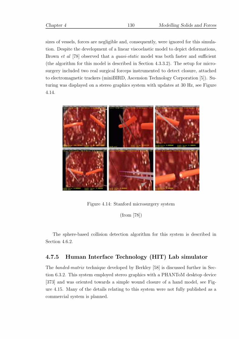
Chapter 4 130 Modelling Solids and Forces
sizes of vessels, forces are negligible and, consequently, were ignored for this simula-
tion. Despite the development of a linear viscoelastic model to depict deformations,
Brown et al [78] observed that a quasi-static model was both faster and sufficient
(the algorithm for this model is described in Section 4.3.3.2). The setup for micro-
surgery included two real surgical forceps instrumented to detect closure, attached
to electromagnetic trackers (miniBIRD, Ascension Technology Corporation [5]). Su-
turing was displayed on a stereo graphics system with updates at 30 Hz, see Figure
4.14.
Figure 4.14: Stanford microsurgery system
(from [78])
The sphere-based collision detection algorithm for this system is described in
Section 4.6.2.
4.7.5 Human Interface Technology (HIT) Lab simulator
The banded-matrix technique developed by Berkley [58] is discussed further in Sec-
tion 6.3.2. This system employed stereo graphics with a PHANToM desktop device
[373] and was oriented towards a simple wound closure of a hand model, see Fig-
ure 4.15. Many of the details relating to this system were not fully published as a
commercial system is planned.
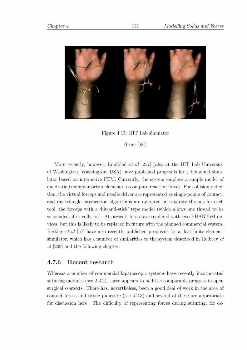
Chapter 4 131 Modelling Solids and Forces
Figure 4.15: HIT Lab simulator
(from [58])
More recently, however, Lindblad et al [257] (also at the HIT Lab University
of Washington, Washington, USA) have published proposals for a bimanual simu-
lator based on interactive FEM. Currently, the system employs a simple model of
quadratic triangular prism elements to compute reaction forces. For collision detec-
tion, the virtual forceps and needle driver are represented as single points of contact,
and ray-triangle intersection algorithms are operated on separate threads for each
tool, the forceps with a ‘hit-and-stick’ type model (which allows one thread to be
suspended after collision). At present, forces are rendered with two PHANToM de-
vices, but this is likely to be replaced in future with the planned commercial system.
Berkley et al [57] have also recently published proposals for a ‘fast finite element’
simulator, which has a number of similarities to the system described in Holbrey et
al [209] and the following chapter.
4.7.6 Recent research
Whereas a number of commercial laparoscopic systems have recently incorporated
suturing modules (see 2.3.2), there appears to be little comparable progress in open
surgical contexts. There has, nevertheless, been a good deal of work in the area of
contact forces and tissue puncture (see 4.2.3) and several of these are appropriate
for discussion here. The difficulty of representing forces during suturing, for ex-

Chapter 4 132 Modelling Solids and Forces
ample, has prompted Kitagawa et al [235] to investigate the use of compensatory
feedback methods for daVinci system. Knot-tying by five experienced surgeons was
tested under various feedback conditions: none, auditory and visual. Visual feed-
back was found to be most effective, although auditory information also provided
some support.
Batteau et al [51] used CathSim (see 2.3.5.2) to present a needle puncturing
task which allowed the authors to investigate user perception to effects such as
haptic recall and latency. In first of two experiments, 27 volunteers (with a range of
experience) were asked judge when the forces felt most appropriate after increasing
the gain on the device over regular increments. The results revealed a very wide
range in ability of the subjects to recall haptic events, which was uncorrelated with
experience. In the second experiment, latency in the force feedback was gradually
increased, and then decreased, to the level of the user’s perception, generating low
and high values of acceptable latency. The authors reported that a large proportion
of the test population were unable to discriminate latencies of 54ms (19ms was the
lowest value reported), suggesting that for some tasks, haptic update rates may be
significantly reduced.
Lee et al [248] have presented a novel method of contact modelling between rigid
surgical tools of arbitrary shape and deformable virtual organs bounded by trian-
gular mesh surfaces. The authors used a ‘divide and conquer’ strategy, based on
the minimisation of an energy function, to redistribute an arbitrary field of displace-
ments onto virtual surfaces. The computational complexity was found to depend
on the size of the touch field. Figure 4.16 gives an illustration of the results: the
red arrows (left figure) indicate the applied forces, whilst the blue arrows (central
figure) show the redistribution of force vectors onto nodes of the mesh.
Figure 4.16: Redistribution of forces (from Lee et al [248])

Chapter 4 133 Modelling Solids and Forces
Some new initiatives for the application and development of VR tools may also be
mentioned here. Several groups, for example, have proposed open-source frameworks
to help stimulate and combine research efforts, notably: Montgomery et al and
Spring [81, 280]; and, Cavasoglu et al and GiPSi [92]. As far as the author is aware,
however, analyses using these tools have yet to be published. In contrast, Ridgway et
al have managed to reverse the usual trend by using ICSAD to assess the efficiency
a new suturing technique [338].
Chapter 5
Design and Implementation
This chapter draws together ideas and elements of design from previous
chapters with the objective of creating a usable training simulator. The first
section describes a number of exploratory investigations using material ob-
tained from CD-rom ‘tutors’ and observation of trainees and surgeons. Sec-
tion 5.2 details the adopted design pattern in its basic form, and extensions
suggested by other work reviewed. Section 5.3 discusses the current imple-
mentation along with hardware and interface issues which also had to be
solved.
‘I always say that nothing is to be done in education without steady and
regular instruction, and nobody but a governess can give it.’
- Jane Austen, Pride & Prejudice (c.1813)
5.1 Preliminary investigations
5.1.1 CD-ROM tutors
5.1.1.1 PrimeSkills in Surgery
In 1996, Edwards and Trigwell wrote of the coming crisis in surgical training [143]:
whilst surgical techniques were becoming more technically demanding and patients
134

Chapter 5 135 Design and Implementation
less forgiving, ‘there is less time to train the junior surgeons, and less time to allow
the juniors to do the operations themselves’. Recognising also that textbooks go
out of date sometimes before publication, the authors proposed that new methods
of tutoring were required. A further criticism of such texts was the lack of precision:
quoted distances, for example, may be given as ‘small’ rather than, say, 4–5 mm. For
surgical trainees, apprenticeships only aggravate this problem, since the consultant
in charge of a procedure is usually too busy to be specific for their benefit [M.
Edwards personal communication, October 2002].
To address these issues, the authors compiled a series of several training pro-
grammes in CD-rom format. The ‘Prime Skills’ CD [142] gives a book-like display
with a schedule of key points about given procedures and related tools eg. Figure 5.1.
Figure 5.1: Prime Skills schedule
(from [142])
For the present project, the clarity of the description for the use of needle holders
was especially laudable. Three principal actions were described:
• Rotation: prior to inserting (or withdrawing) the needle, the surgeon uses a
‘screw-driver’ rotation to bring the needle into position, ideally at an angle of
Chapter 5 136 Design and Implementation
90◦ to the tissue surface and to the orientation of the wound. The amount of
rotation needed may be 180◦ or more.
• Pressing: this is often an unexpected requirement for beginners when learning
to suture surface wounds. When needed, the surgeon must press firmly onto
the tissue with the jaws of the needle holder so that space is created for the
needle to enter. Failure to create adequate space makes the needle difficult to
handle and may bend the needle.
• Curving: through tissue, movement of the needle is not a simple screw-driver
rotation: the surgeon has to follow the curvature of the needle. A beginner
who tries to rotate around the holding position may find that the needle will
break.
Commenting on these programmes, Thomas [418] has pointed out that although
suturing a jiffy bag was unrealistic, the didactic format with timed exercises was
very suitable for junior trainees (some errors, notably in knot-tying and handling
needles by hand, were also indicated). In a similar scheme, O’Connor et al [305]
found that first year medical students trained for 3–4 hours on a computer-based
learning module were indistinguishable from final year medical students in terms of
an Objective Structured Clinical Examination1.
5.1.1.2 The Suture Tutor Kit
To assist with the current investigation, the ‘Suture Tutor Kit’ was purchased from
Limbs & Things (part no. 90024 [20]). The kit contained a synthetic skin pad,
scalpel, forceps, needle driver, needle and a tutorial CD-rom. Advice on practising
various stitch types and knotting information was presented, eg. see Figure 5.2. It
is notable that for closure of surface wounds, as represented by the skin-pad, both
hands must work in coordination, with the non-dominant hand in a supportive role.
Use of the kit was made during later evaluation (Chapter 7) and the CD-rom was
particularly valuable for examples of handling instruments correctly (see Appendix
C).
Much more tutorial information is now available on the web at eg. [15, 19].
1The authors cautioned that the first-year students were trained very close to the time of theexamination and, as such, may have had an advantage; also, retention was not tested. Readersshould also note earlier comments about misuse of the null hypothesis in Section 3.3.1.
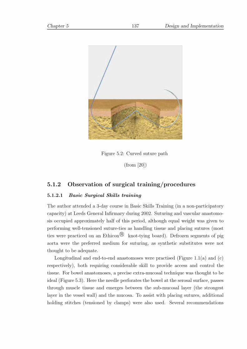
Chapter 5 137 Design and Implementation
Figure 5.2: Curved suture path
(from [20])
5.1.2 Observation of surgical training/procedures
5.1.2.1 Basic Surgical Skills training
The author attended a 3-day course in Basic Skills Training (in a non-participatory
capacity) at Leeds General Infirmary during 2002. Suturing and vascular anastomo-
sis occupied approximately half of this period, although equal weight was given to
performing well-tensioned suture-ties as handling tissue and placing sutures (most
ties were practiced on an Ethicon r© knot-tying board). Defrozen segments of pig
aorta were the preferred medium for suturing, as synthetic substitutes were not
thought to be adequate.
Longitudinal and end-to-end anastomoses were practised (Figure 1.1(a) and (c)
respectively), both requiring considerable skill to provide access and control the
tissue. For bowel anastomoses, a precise extra-mucosal technique was thought to be
ideal (Figure 5.3). Here the needle perforates the bowel at the serosal surface, passes
through muscle tissue and emerges between the sub-mucosal layer (the strongest
layer in the vessel wall) and the mucosa. To assist with placing sutures, additional
holding stitches (tensioned by clamps) were also used. Several recommendations

Chapter 5 138 Design and Implementation
Figure 5.3: Extra-mucosal suture technique
(from [350])
were also made at the course including: (i) beneficial use of low-powered magnifying
aids to focus on the area of the wound; (ii) development of ‘palm’ technique, in
which the needle holders are held in the palm of the hand and are therefore closer
to the axis of rotation; and (iii) use of little fingers, wrist etc. to support or steady
the hand in placing sutures.
5.1.2.2 A corotid endarterectomy
The author observed a single endarterectomy procedure during March 2002. The
operation involved removing a blockage from the main artery to the brain, situated
in the neck of the patient, via a longitudinal arteriotomy. The diseased area was
identified by a yellowish-blue tinge. The vessel was clamped to either side of the
diseased area before being opened and then cleared by hand and by irrigation. Af-
terwards, a shunt (bypass tube) was placed into the artery before unclamping. The
use of the shunt was significant for several reasons:
• The initial part of the procedure, whilst blood flow was prevented, had to be
carried out very quickly and efficiently, taking perhaps no more than a few
minutes. The consultant in charge undertook this.
• The shunt was placed into the artery to maintain blood flow to the brain
during the rest of the procedure, principally the suturing of the vessel.

Chapter 5 139 Design and Implementation
• To avoid causing a restriction of the vessel, a Dacron (synthetic) patch was
cut to shape over the wound and sutured in place, working around the bypass
tube.
• Because working was hampered by the shunt, and the position of the wound
within the joint of the neck, ‘perfect’ approach angles of 90◦ were not available.
This part of the procedure took over an hour to complete and was conducted
by the consultant and assisting registrar.
• Closure of the wound, using a sub-cuticular (sub-surface) technique took ap-
proximately 5 minutes, and was undertaken by the registrar.
5.1.3 Motion analysis
5.1.3.1 Objectives
To examine and define possible ‘flight path’ criteria for suturing, Holbrey et al
devised a simple system to track subjects whilst suturing a foam pad [210]. An
Ascension Flock of Birds magnetic tracking device was employed for tracking and 7
dof for the hand and elbow were recorded (3D position and quaternion information).
Angles of interest were converted into wound-based coordinates via a simple setup
routine based around the location of a straight-line wound, see Figure 5.4. Time was
also recorded, since the Flock was sampled at a graphics frame rate (25 Hz), but was
not explored further here, since speed does not necessarily reflect good technique.
Also, variation between individuals (novices, experts etc. see 2.2.2) would not allow
ready comparison unless other techniques, such as say, dynamic time warping [309],
were introduced.
5.1.3.2 Preliminary results
As the distinction between pure rotational movement and curving (see 5.1.1) was not
appreciated until later, pure rotation (define here as γ; obtained by matrix analysis)
was thought to be a prime candidate for standardizing individual movements. Figure
5.5 shows four attempts by different subjects (members of the School of Computing
with no suturing experience) to suture a foam pad. Part (a) shows that all subjects
can be seen to vary the orientation of the needle-driver during insertion, although
small variations of a few degrees might be acceptable (this would be difficult to
quantify by human observers). In part (b), one user is attempting to force the

Chapter 5 140 Design and Implementation
Figure 5.4: Local coordinate/angle system
Figure 5.5: Suture technique by angular criteria
Chapter 5 141 Design and Implementation
needle through by varying the height of the tool, rather than employing full rotation
of the wrist, and is very likely causing excessive stress in the tissue.
5.1.3.3 Discussion
Whilst these data appeared to give promising results, use of the Flock was found
to be too restrictive. In particular, the device was thought to be too sensitive
to the steel instruments employed during the test so that the sensors had to be
worn on the arm or back of the hand. This led to significant errors when the
hand was flexed and would probably have made the apparatus unusable for more
complex anatomical models. Also, this form of analysis (eg. local coordinate angles,
matrix/eigenvector analysis for axis of rotation) was felt to be too complex to give
readily understandable feedback to the user, even using graphical techniques such
as the ‘guide-vector’ condition of the BDI study 2.4.3.3.
5.2 Design
5.2.1 Sub-tasks of the procedure
5.2.1.1 A model operative procedure
Payandeh et al [312] have described the main sub-tasks for suturing as comprising
the following actions: position needle, bite tissue, pull through needle, re-position,
re-bite, re-pull and pull through. Using the results of the preliminary work carried
out in Section 5.1, Payandeh’s scheme is developed here to give a breakdown of the
main sub-tasks for a typical vascular procedure, see Table 5.1. This is not intended
to be all-embracing, but to give sufficient context to plan the setting of the VR
environment.
5.2.1.2 Selection of sub-tasks
Although suturing is not the only important component of vascular surgeries, a sur-
geon commonly has to be able to sustain an impeccable level of suturing technique,
possibly for several hours at a time. The focus of the current design is, therefore,
oriented towards the acquisition and maintenance of a high degree of skill using a
suturing needle. Knot-tying has been excluded, not because it is any less important,
but because it is very difficult to represent with currently available VR interfaces

Chapter 5 142 Design and Implementation
Sub-task Description Technique/tools
(a) Orientate patient Surgeon takes apt stance or movespatient into position for maximumcomfort
Operating tableand equipment
(b) Open wound area Retraction of skin and sub-cutaneous fat etc.
Scalpel, retrac-tors, clamps(probably held byassistants)
(c) Identify diseasedarea
Tissue probed and examined for dis-colouration by surgeon in good light
Forceps, magni-fier (head-worn)
(d) Arteriotomy Vessel opened longitudinally ortranversely
Clamps, scissors,forceps
(e) Clearing obstruc-tions
Removal of plaques, disease etc. Forceps, irriga-tion
(f) Shunting Insertion of bypass tube Clamps, bypasstube
Suturing:(g.1) Select needle According to size of bite required,
strength and type of needle and su-ture thread type. Diseased or cal-cified areas may require a strongerneedle
38 circle needle ofvarious point andthread types, nee-dle holder (vari-ous types)
(g.2) Mount needle The needle is usually mounted sothat the point is forward of 90◦
Needle holder,forceps
(g.3) Rotation The arm is pivoted into position forperpendicular entry into the vessel
(g.4) Pressing orcontrolling tis-sue/needle
Needle driver or forceps used to firmthe tissue prior to insertion or re-moval of the needle. In vascularsurgery, forceps may be used to holdthe needle, prior reclamping
(g.5) Insertion or with-drawal
This action requires the curving mo-tion described in Section 5.1.1.
Patch for longitu-dinal wouds
(g.6) suture tie or nee-dle re-mounted
(h) Closure of woundarea
Removal of shunt, clamps etc. andsuturing of surface tissues
Table 5.1: Sub-tasks of vascular procedure
Chapter 5 143 Design and Implementation
(see 4.3.3.3) and, arguably, has a very good approximation by analogues like the
Ethicon r© tying board.
A further consideration was that the task should not be so simple or repetitive
as to induce a block training effect (see 3.5.8), but should represent a reasonable
facsimile without being overpowering. It was especially desirable that the user should
be able to set, collect and release the needle at critical points during the procedure.
Furthermore, it should be possible to build up skill levels, so that say, for example,
the non-dominant hand should also be able to perform the task.
5.2.2 Basic design elements
5.2.2.1 The operating environment
Ideally, the surgeon stands at the operating table, looking down at the patient,
keeping the arms in at the sides and the elbows flexed at an angle of roughly 90◦ [142].
The surgeon often has to spend many hours in this position and comfort is therefore
important. In order to allow hands, wrists etc. to be steadied in line with sub-task
(a) of Table 5.1, it was vital that the scene should be capable of manipulation.
Unfortunately, it is not easy to allow haptic devices to be reset, given their limited
workspace (see 4.1.3) and, consequently, manipulation of the scene must be led by
the graphical application and forces adjusted accordingly.
5.2.2.2 Use of either or both hands
Following the findings of earlier research on suturing simulation (see 2.4.3), a prin-
cipal objective was to incorporate the use of both hands, henceforth denoted as DH
(dominant hand) and NDH (non-dominant hand). It should be made clear, however,
that for vascular work the NDH does not usually play the same role in restraining
tissue as it does for surface wounds. Indeed, it is thought to be bad practice to
manipulate vessels directly with forceps, although unavoidable at times. Holding
and manipulating the needle or patch with forceps is required and at some point it
is common for vascular surgeons to have to learn to suture with the NDH.
The attempt to include 2-handed technique immediately suggests several design
constraints:
• The deformable model must be capable of representing multiple simultaneous
contact points and for vascular models, the choice of contact points must be

Chapter 5 144 Design and Implementation
reasonably large (given the relatively large surface area compared to eg. a liver
model);
• The deformable model should be sufficiently accurate so that overlaying de-
formations, or making large-scale changes with the NDH does not distort the
model unduly;
• Collision detection routines must be able to handle multiple contacts at differ-
ent levels of resolution
– globally across the mesh at a graphical frame-rate (> 25 Hz),
– locally at contact with the needle at a haptic frame-rates (1000 Hz);
• The choice of devices for the DH and NDH should permit the angle of the
needle to be set and retrieved as naturally as possible.
The asymmetric action of the hands reflects the behaviour described by Guiard [190]
(see 3.5.10) and, given the requirement for collision detection (at different levels of
resolution), suggested that some degree of parallel processing or threading would be
advantageous: the first, with a slower, graphical frame-rate representing the NDH;
and the second, with a faster haptic frame-rate, for the DH. The need for realistic
deformation and forces suggested that FEM was preferable for soft tissue modelling.
Given the complexity of the method, FEM and modifications for the present research
are discussed in Chapter 6.
5.2.2.3 Finite state modelling
Table 5.2 describes a unique set of needle states associated with the suturing sub-
tasks (g.1-g.6) listed in Table 5.1 with additional states to allow control of collision
detection and forces.
5.2.2.4 Feedback
The careful segregation of needle states described above (5.2.2.3) allows data to be
collected during strictly defined periods of entry, exit etc. Given previous work,
and research into training schedules (3.5.8) and augmented feedback (3.5.9), it was
thought to be particularly important to allow users to train for an extended period
and to be able to obtain feedback when requested. Such feedback should be straight-
forward to comprehend, but should also aim to exploit the capabilities of the VR
environment. In particular, it should aim to:-

Chapter 5 145 Design and Implementation
Needle state Description
Rest Needle returned to rest position to practice grabbingGrabbed Needle picked up, ready to set angle for forehand or
backhand working etc.Pre-touch A region ‘in front of’ the point of the needle is in con-
tact with the mesh: one (or more) triangles can now benominated for the local haptic scheme
Touching The needle is in contact with the mesh but has notpierced it: forces act against the direction of approach
Inserted Some criterion has been met (see below) to allow theneedle to enter: forces now act across the surface to-wards the point of entry
Pierced The needle has emerged on the opposite side of the meshRelaxing The needle has been released and hence the mesh/needle
should relax to a rest positionEmbedded The needle is at rest in tissueRegrab-test The needle is grabbed again, but a test is necessary to
establish whether the needle is being inserted furtherthrough or being withdrawn
Regrabbed If the regrab-test shows that the needle has beengrabbed nearer the point, the needle is being pulledthrough and hence it has been regrabbed. Otherwisethe needle state should revert to ‘Pierced’
Suture As the needle is pulled through, tension remains on themesh due to the suture/knot
Override Added to facilitate jumps between states (see text)
Table 5.2: Finite states
Chapter 5 146 Design and Implementation
• Be both descriptive (numeric) and prescriptive (ie. to suggest movement cor-
rections).
• Avoid cognitive overload eg. by creating a graphical visualization of errors.
• Avoid dependency formation, by only providing feedback when requested.
• Be motivational: improvements should be easily visible.
At the same time, it was clear that tests performed against the clock would also be
required to collect data for assessment of validity and to encourage working under
pressure without additional feedback. It was therefore suggested that the design
should incorporate modes for testing (with a timed task) and for practice (when
feedback can be made available).
5.2.3 Design extensions
Linear finite element models have limited use in general due to their ability to handle
only first order strain terms. This corresponds to the initial elastic Hookean phase
which occurs below the level of 1% strain for most materials. During testing, most
tissues exhibit linear behaviour well beyond this limit (see 4.2.2) and it was therefore
of interest to see how well, or under what circumstances, stable behaviour for linear
FEM continued beyond this limit. It should also be possible to qualify the stability of
models by assessing properties such as volume conservation with respect to different
elastic coefficients.
If regions of stability could be established, then it might also be possible to
generate approximations to non-linear viscoelastic responses in the manner suggested
by Raghavan et al (see 4.2.2) and explored by Cotin et al [113] (see 4.3.4.4).
5.3 Implementation
5.3.1 Approach
The principle of the asymmetric division of labour developed by Guiard is used
as a central feature of the design here (3.5.10). In his theory, Guiard supposed
that the hands might be represented by separate motors, each capable of producing
some action independently, but most often acting together (or ‘co-operating’), as
if assembled in series. This concept is fully adopted here, although it is necessary

Chapter 5 147 Design and Implementation
to suppose that there are additional mechanisms by which information is fed back
from one motor to the other. In essence, asymmetry is used to imply that the NDH
leads, but makes larger movements at a slower rate, whilst the DH lags, but exhibits
finer control and timing is much more critical. The computational load is therefore
divided between two processes which support and represent the activities of the
hands as follows:
NDH represented by a slow cycle of movement (ie. a computational loop which
operates at a graphics frame rate of c.30 Hz), in which changes to the
mesh by the NDH drive updates to collision detection and graphical state
of the entire mesh;
DH a much faster computational cycle which generates deformation and force
computations by considering contacts with one or more contact triangles,
which may be determined by the NDH.
Ideally, we might wish that these processes could operate autonomously. In
practice, however, it is necessary to consider a third motor, since the PHANToM
haptic device creates its own process and requires strict updates at 1000 Hz. In the
kinematic chain of Figure 5.6, therefore, the haptic driver is set to rotate at 1000
Hz, whilst the graphics loop has to cycle at 30 Hz. Intriguingly, this scheme would
seem to allow the FEM deformation computations to be carried out at any speed
between these limits. In practice, it was seen that interpolation between FEM force
computations is very noticeable below 200 Hz.
Unlike a simple kinematic chain, Figure 5.6 shows that the computational process
requires a sophisticated communication process to maintain synchronisation:
• The haptic ‘motor’ supplies a current matrix transformation, according to the
position of the endpoint of the PHANToM; during this update (which requires
a mutex in thread terminology), forces computed from the previous matrix
position are returned to the haptic system for rendering.
• The current matrix is used by the DH ‘motor’ to compute interactions and
resultant forces by the needle with the current collision detection mesh; de-
formations are passed to the NDH ‘motor’ in return for any updates to the
current contact triangle;
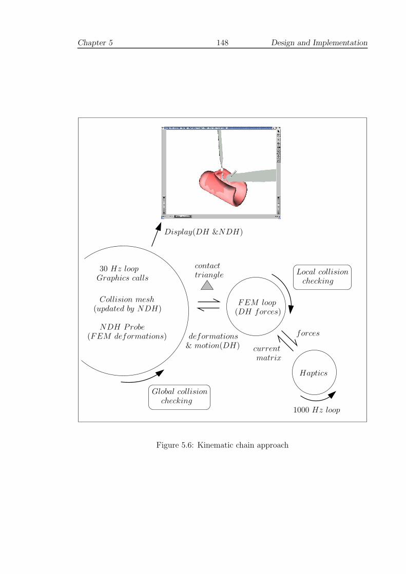
Chapter 5 148 Design and Implementation
checkingGlobal collision
contacttriangle
deformations
currentmatrix
forces
Local collisionchecking
Haptics
(updated by NDH)
NDH Probe
1000 Hz loop
(FEM deformations)
30 Hz loop
Collision mesh
Display(DH &NDH)
Graphics calls
(DH forces)FEM loop
& motion(DH)
Figure 5.6: Kinematic chain approach
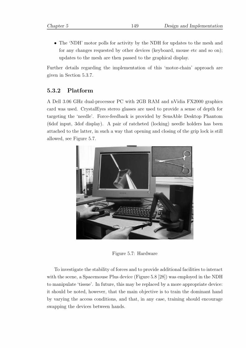
Chapter 5 149 Design and Implementation
• The ‘NDH’ motor polls for activity by the NDH for updates to the mesh and
for any changes requested by other devices (keyboard, mouse etc and so on);
updates to the mesh are then passed to the graphical display.
Further details regarding the implementation of this ‘motor-chain’ approach are
given in Section 5.3.7.
5.3.2 Platform
A Dell 3.06 GHz dual-processor PC with 2GB RAM and nVidia FX2000 graphics
card was used. CrystalEyes stereo glasses are used to provide a sense of depth for
targeting the ‘needle’. Force-feedback is provided by SensAble Desktop Phantom
(6dof input, 3dof display). A pair of ratcheted (locking) needle holders has been
attached to the latter, in such a way that opening and closing of the grip lock is still
allowed, see Figure 5.7.
Figure 5.7: Hardware
To investigate the stability of forces and to provide additional facilities to interact
with the scene, a Spacemouse Plus device (Figure 5.8 [28]) was employed in the NDH
to manipulate ‘tissue’. In future, this may be replaced by a more appropriate device:
it should be noted, however, that the main objective is to train the dominant hand
by varying the access conditions, and that, in any case, training should encourage
swapping the devices between hands.
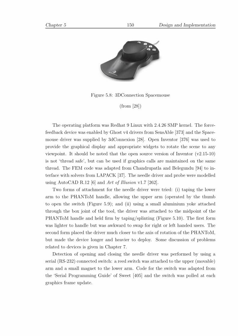
Chapter 5 150 Design and Implementation
Figure 5.8: 3DConnection Spacemouse
(from [28])
The operating platform was Redhat 9 Linux with 2.4.26 SMP kernel. The force-
feedback device was enabled by Ghost v4 drivers from SensAble [373] and the Space-
mouse driver was supplied by 3dConnexion [28]. Open Inventor [376] was used to
provide the graphical display and appropriate widgets to rotate the scene to any
viewpoint. It should be noted that the open source version of Inventor (v2.15-10)
is not ‘thread safe’, but can be used if graphics calls are maintained on the same
thread. The FEM code was adapted from Chandrupatla and Belegundu [94] to in-
terface with solvers from LAPACK [37]. The needle driver and probe were modelled
using AutoCAD R.12 [6] and Art of Illusion v1.7 [262].
Two forms of attachment for the needle driver were tried: (i) taping the lower
arm to the PHANToM handle, allowing the upper arm (operated by the thumb
to open the switch (Figure 5.9); and (ii) using a small aluminium yoke attached
through the box joint of the tool, the driver was attached to the midpoint of the
PHANToM handle and held firm by taping/splinting (Figure 5.10). The first form
was lighter to handle but was awkward to swap for right or left handed users. The
second form placed the driver much closer to the axis of rotation of the PHANToM,
but made the device longer and heavier to deploy. Some discussion of problems
related to devices is given in Chapter 7.
Detection of opening and closing the needle driver was performed by using a
serial (RS-232) connected switch: a reed switch was attached to the upper (movable)
arm and a small magnet to the lower arm. Code for the switch was adapted from
the ‘Serial Programming Guide’ of Sweet [405] and the switch was polled at each
graphics frame update.
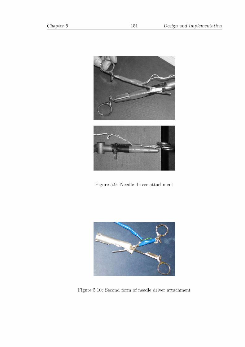
Chapter 5 151 Design and Implementation
Figure 5.9: Needle driver attachment
Figure 5.10: Second form of needle driver attachment

Chapter 5 152 Design and Implementation
5.3.3 Display and posture
For the comfort of the user, an Open Inventor browser display was used, which
allows the rotation of the scene using the ‘thumbwheel’ widgets at the base of the
display with the mouse pointer. One of the ‘thumbwheels’ allows the camera to
be dollied ie. moved backwards and forwards to magnify the scene (as if magnifiers
were being worn). Stereo display was available through the graphics sub-system and
OpenGL related calls in Inventor. Graphics-based calls also allowed the ‘grab’ and
‘tilt’ angles of the needle to be set for comfortable working, Figure 5.11.
Figure 5.11: Setting the needle angle
Using a combination of these angles, it is possible to set up the needle for at
least four positions of working, Figure 5.12. The figure shows that a combination of
techniques may be employed on entry and exit, and ideally, all should be practiced.
Note that when the needle holder is open, the tool appears as semi-transparent.
This is to aid with aligning the tool to the needle. Otherwise, if the jaws are not
at tangent, the needle will be rocked into tangential holding position. Also, to aid
grasping the needle, a crosshair (not shown) appears when the needle holder is ‘in
range’. It is convenient here to offer definitions of various error types (refer to Figure
5.13):
• edge direction error: the angular difference between the needle normal and the
direction of the nearest edge;

Chapter 5 153 Design and Implementation
(a) (b)
(c) (d)
(e)
Figure 5.12: Setting working positions
(NB. red/green/blue axes are for this illustration only)
where:(a) indicates the most common forehand (FH) position ie. FH upright(b) shows that the needle is tilted downwards, so that the movement is a backhandrotation (FH inverted)(c) indicates the most straightforward backhand (BH) needle mounting (BH upright)(d) shows the needle tilted downwards from (c), so that the movement is a forehandrotation (BH inverted)(e) shows an ‘overhand’ regrab of the needle (same configuration as (d) — BHinverted). Note that the needle driver is set to be semi-transparent when opened(see text).
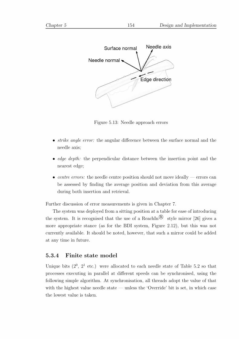
Chapter 5 154 Design and Implementation
Figure 5.13: Needle approach errors
• strike angle error: the angular difference between the surface normal and the
needle axis;
• edge depth: the perpendicular distance between the insertion point and the
nearest edge;
• centre errors: the needle centre position should not move ideally — errors can
be assessed by finding the average position and deviation from this average
during both insertion and retrieval.
Further discussion of error measurements is given in Chapter 7.
The system was deployed from a sitting position at a table for ease of introducing
the system. It is recognised that the use of a ReachIn r© style mirror [26] gives a
more appropriate stance (as for the BDI system, Figure 2.12), but this was not
currently available. It should be noted, however, that such a mirror could be added
at any time in future.
5.3.4 Finite state model
Unique bits (20, 21 etc.) were allocated to each needle state of Table 5.2 so that
processes executing in parallel at different speeds can be synchronised, using the
following simple algorithm. At synchronisation, all threads adopt the value of that
with the highest value needle state — unless the ‘Override’ bit is set, in which case
the lowest value is taken.
Chapter 5 155 Design and Implementation
This is necessary since each process must maintain separate copies of state vari-
ables and states do not always advance. Consider the example of grabbing and
releasing the needle when the needle is embedded in the tissue model. The reed
switch attached to the needle holder is sampled to detect open or closed state at a
fairly low (eg. graphical) frame-rate. If the needle holder was found to have closed
onto the needle, then the slower thread would then determine that forces should be
resumed on the faster (haptic frame-rate) thread. If the needle is still being pushed
through from the side of initial entry, the Override bit is set and the system can
resume sending forces in the ‘Pierced’ state. Otherwise, the system can advance to
the ‘Regrabbed’ state and the needle will be allowed to exit legally ie. a stitch has
been properly completed.
A suture-thread model was not attempted at this stage and hence ‘state’ for
this level of interaction was not implemented. The main reason for this was that
in vascular surgery the sides of the wound are seldom drawn together in the same
manner as surface wounds. For example, in longitudinal working, a patch is often
used to avoid creating a restriction of the vessel. In end-to-end anastomoses, some
‘pursing’ of the tissues is inevitable and is one reason for the use of the extra-mucosal
technique (see Figure 5.3). This aspect of the present research has therefore been
simplified and would be an appropriate area to consider for future work.
5.3.5 Bimanual working
The Spacemouse can be used essentially as a joystick to move a virtual ‘probe’, which
for convenience has a ‘hit-and-stick’ type functionality. This allows the needle to be
used as in the sequence of figures shown in Figure 5.14. An advantage of using the
Spacemouse is that it allows the user access to 11 buttons which can be programmed
to rotate the needle, activate test mode etc. without requiring the NDH to move
from a relatively fixed position. Such facilities can and have been made available
through using the keyboard or mouse pointer, but unfortunately, this requires the
user’s attention to be diverted, making the task considerably more difficult.
5.3.6 Collision detection
A number of collision detection libraries are available in the public domain. Most,
however, employ fixed bounding box techniques to optimise detection for rigid bod-
ies. The author is aware of only one exception — the SOLID library of van den
Bergen [430], which does not yet cope with deformable structures [van den Bergen,

Chapter 5 156 Design and Implementation
Figure 5.14: Working with both hands
personal communications, June 2002–July 2003]. The hardware based methods of
Lombardo et al (and others, see 4.6.3) would appear to offer greater scope. The
curved shape of the needle, however, did not suggest a simple viewing volume, but
rather that a simple ray-based technique might be more appropriate.
The solution adopted here was to separate the basic roles of collision detec-
tion into two main components, within the ‘motor’ design of Figure 5.6. Since the
‘needle’ can readily be represented by a collection of line segments, a ray-plane in-
tersection test was devised, comprising three basic stages: (i) ray-plane intersection;
(ii) barycentric coordinate computation; and (iii) segment-plane intersection. The
collision checking algorithm was adapted according to the position in the kinematic
chain and the flow of information is described below. Through trial and error, it
was found that stability of the triangle nomination scheme was improved if an ad-
ditional ray segment (ie. a ‘probing’ segment) was tested in front of the point of
the needle, Figure 5.15. The length of the probe was set at twice the distance of
previous displacement vector.

Chapter 5 157 Design and Implementation
Previous endpoint position
“Probe”
Needle centre − line(simplified)
Figure 5.15: Needle probe
5.3.7 Processes of the kinematic chain
5.3.7.1 Haptic cycle
The Ghost driver employs threading to provide a real-time schedule, suggesting a
mechanism to manage the timing of the threads for parallelisation. In practice, user
safety is improved and the interpolation of forces is easier to achieve (ie. extrapola-
tion is unnecessary), if the graphic and haptic displays are delayed by a single video
frame (the Phantom must still receive updates at 1000Hz for smooth forces).
5.3.7.2 FEM cycle
This thread was permitted to execute at slower speeds than the haptic thread, and
the force data interpolated as necessary. The interpolation of forces was found to
give poor results if updates were dropped below c.250 Hz and 333 Hz was the lowest
value used in practice. For most models used in testing and evaluation, however,
updates at 1000 Hz were achievable and this rate should be assumed unless otherwise
specified.
For the local collision detection algorithm, data for the nominated triangle are
created and updated during synchronisation with the graphic cycle (see 5.3.7.3). If

Chapter 5 158 Design and Implementation
an intersection is confirmed in the FEM loop, the nomination becomes fixed locally
until contact is lost. Barycentric coordinates are used to distribute the impact
of the ‘needle’ by weighting each node of the entry face accordingly, the resulting
deformations being superimposed. Thus, even if the tool leaves the area of the
original triangle, the fidelity of FEM solution can still be maintained.
The angle of entry and a velocity test of the ‘needle’ endpoint are used to de-
termine whether the mesh has been pierced. If so, the segments of the ‘needle’ are
tracked through the mesh to determine appropriate releasing and re-grabbing.
5.3.7.3 Graphic cycle
The graphic thread is responsible for updating the mesh used in the global collision
detection algorithm and for passing graphics calls. A set of valid exterior triangles
is initially defined (by computing face normals) which is tested at each pass of the
graphics loop. If valid planar intersections are found to lie within the test triangle
(by checking barycentric coordinates) and the ends of the colliding segment are
found to lie to either side of the plane, then the intersected triangle is promoted to
the FEM scheme.
Multiple collisions must be checked for plausibility. Since ‘surgical’ errors may
still occur through poor technique, the global collision checking scheme continues to
check the defined mesh set after this point. Manipulation of the mesh by the NDH
causes the collision detection mesh (and normals) to be updated.
5.3.7.4 Display cycle
The display was considered to form an additional level in the flow of information
through the system since the deformation state which arises through interaction
of the ‘needle’ (eg. by the DH) is only superimposed graphically (with normals
etc. being recalculated for shading). The content of the ‘needle’ interaction buffer
was otherwise ignored for collision detection, as, if this were not the case, the delay
in timing would cause force discontinuities.
5.3.8 Feedback on performance
Two forms of feedback were proposed and implemented (in practice mode):
Real-time A simple real-time condition which was to mark the position of the centre
of the needle graphically so that movement could be observed while

Chapter 5 159 Design and Implementation
inserting the needle. The centre was marked by a small blue sphere, see
Figure 5.11, and was intended to be minimally obtrusive. The marker
can be switched off if the user prefers.
Delayed In practice mode, the normal of entry and exit planes is averaged and can
be displayed as a series of individual semi-transparent ‘planes’ (orange-
coloured for entry and greenish-blue for exit). Similarly the average
position of the centre marker is given, also for entry and exit, by semi-
transparent orange and green marker spheres. The radius of each sphere
was set to one standard deviation of the movement away from the centre
(strictly: the radius was the square root of the sum of the variances in
x, y and z directions). After completing a number of stitches, the user
can click the right mouse button to view the scene as in Figure 5.16.
A small cylindrical marker was placed at the position of the entry point to indicate
the position of a successful suture. The mode of delayed feedback has a number of
advantages which may be briefly outlined as:
• straightforward concepts (unlike stress or rotation axes) which are easy to
understand;
• enabling the display of average entry and exit planes, and therefore the average
difference;
• the model can be rotated in 3D to examine edge intersection direction eg. Fig-
ure 5.16(b);
• centre-markers are easily identified with the concept of the ‘blue-dot’ position;
• the planes are aligned with entry points, giving an additional cue to spacing.
If the centres are not aligned with the planes, this indicates a further source of
tissue stress ie. the needle was moved, but kept aligned with its average plane:
this is referred to as ‘out-of-plane’ stress in later chapters.
Yerkes-Dodson (Section 3.5.5.1) showed that learning took place best under pressure,
if not excessive: it was supposed that timed trials (3 minutes) were useful to add a
modest degree of pressure. During these trials, neither the plane nor centre-marker
feedback were available.
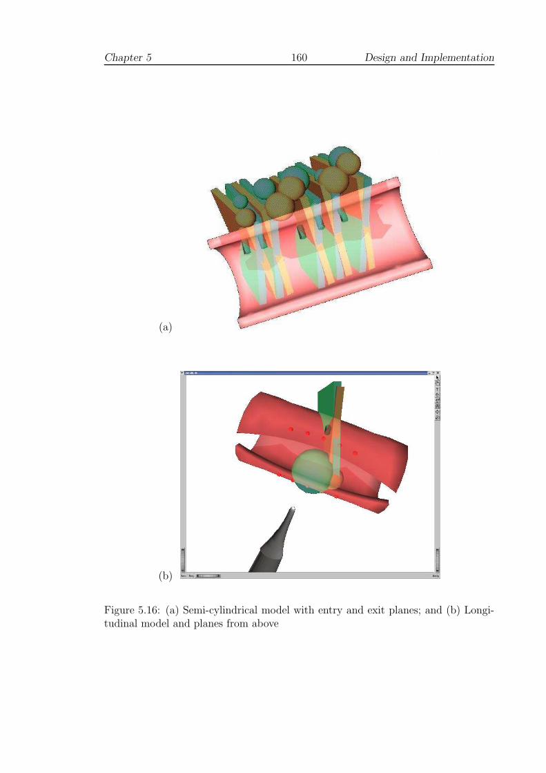
Chapter 5 160 Design and Implementation
(a)
(b)
Figure 5.16: (a) Semi-cylindrical model with entry and exit planes; and (b) Longi-tudinal model and planes from above

Chapter 5 161 Design and Implementation
5.3.9 Discussion
Several ideas were discussed as possible areas of investigation, for which partial
solutions were implemented here but which may merit further analysis in future.
One such area was the problem of assessing when the needle has perforated the
tissue.
The use of FEM to model the tissue suggested that it may be possible to model
this process by using stress analysis. Whilst this would have been ideal in many
respects, the difficulty arises that the use of a pre-computation step prevented topo-
logical changes and it was not possible to analyse stress levels caused by eg. insert-
ing the needle too near to the edge of the tissue. It is possible, of course, to model
perforations in the mesh, but although this was attempted, the collision detection
algorithm as outlined did not permit interaction. In any case, a more convincing
test, to be undertaken perhaps in future, would be to create a finer mesh and analyse
stress levels (off-line) as perforations are placed nearer to the edge of the mesh.
The use of a velocity test to determine insertion, rather than stress, was based
upon the suggestion by surgeons that the needle must be used with a certain amount
of conviction. This would almost certainly depend upon the level of disease within
the tissue and is therefore a fairly subjective quantity at present. Again, further
work might determine appropriate values for such parameters and the use of FEM
would certainly be an advantage in this respect (the choice of parameters set is
discussed further in Chapter 7).
One reason that this problem was not pursued further here was that the Desktop
PHANToM is unable to return torque forces. It would have been useful, for example,
to attempt to model sub-surface layers (or disease) in the tissue in the manner
suggested by Frick et al (see 4.2.3). This would, however, have required torque
forces to indicate resistance to curving the needle.
Chapter 6
Solid Mechanics and FEM
This first part of this chapter gives a formal definition of the FEM based
upon solid mechanics, elasticity theory and the principle of virtual work devel-
oped by Huebner [216], Lepi [252] and others. This is a very natural approach
but is in fact, a weak formulation (see eg. [106] for a stronger mathematical
proof). Section 6.3 discusses modifications to allow real-time interaction with
vascular models. Section 6.4 examines the stability of these models and pro-
poses an adaption to approximate a two phased linear viscoelastic response.
‘At a pinch I could be a tolerable road-sweeper or an inefficient gardener
or even a tenth rate farm hand. But by no conceivable amount of effort
or training could I become a coal-miner; the work would kill me in a few
weeks.’
- George Orwell, The Road to Wigan Pier (1937)
6.1 Linear elastic solids
6.1.1 Stress and Strain
The static deformation problem can be approached by considering the equilibrium
between states of stress, expressed as force per unit area, and strain, a ratio of
162

Chapter 6 163 Solid Mechanics and FEM
lengths. In one dimension, a bar of uniform cross-section under an axial load can
be modelled: in Fig. 6.1, the left end of the bar is restrained (ie. cannot move) but
Ua
Force
Ub
∆X
∆X + ∆U
x
ba
Figure 6.1: Uniaxial strain of a simple bar (after Lepi [252])
points along the bar are displaced by an amount related to the initial position along
the bar, denoted by U . If the portion of the load applied across an infinitely small
area, ∆A, is ∆F , we have:
normal stress:
σx =∆F
∆A(6.1)
and if the length of the original slice is defined as ∆X and the elongation by ∆U ,
the normal strain is:
normal strain:
εx =∆U
∆X(6.2)
In higher dimensions, partial derivatives must be used since displacement is usu-
ally a function of more than one variable (and we write εx = δuδx
). Unless some
other assumption is made (eg. uniform plane stress or strain), interaction in three
dimensions will generate nine such derivative components. For isotropic materials,
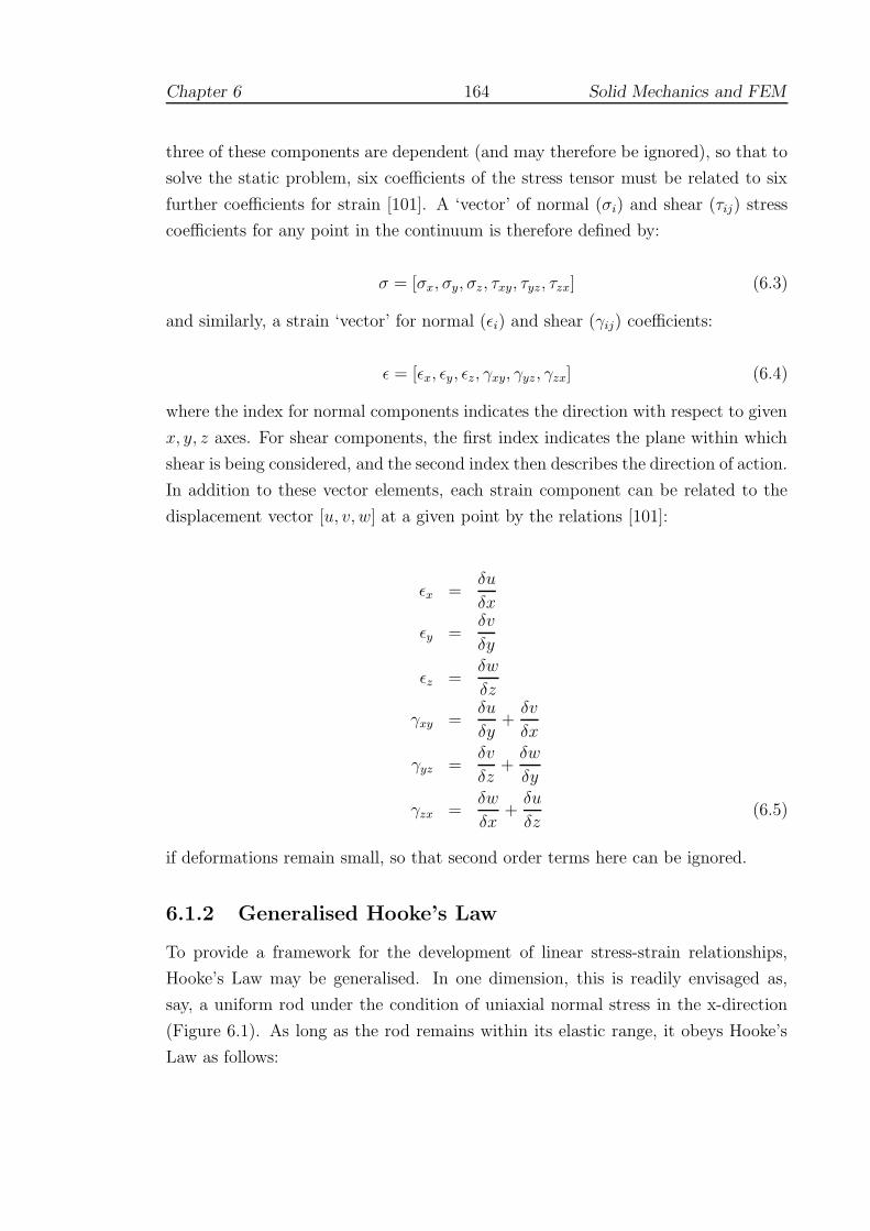
Chapter 6 164 Solid Mechanics and FEM
three of these components are dependent (and may therefore be ignored), so that to
solve the static problem, six coefficients of the stress tensor must be related to six
further coefficients for strain [101]. A ‘vector’ of normal (σi) and shear (τij) stress
coefficients for any point in the continuum is therefore defined by:
σ = [σx, σy, σz, τxy, τyz, τzx] (6.3)
and similarly, a strain ‘vector’ for normal (εi) and shear (γij) coefficients:
ε = [εx, εy, εz, γxy, γyz, γzx] (6.4)
where the index for normal components indicates the direction with respect to given
x, y, z axes. For shear components, the first index indicates the plane within which
shear is being considered, and the second index then describes the direction of action.
In addition to these vector elements, each strain component can be related to the
displacement vector [u, v, w] at a given point by the relations [101]:
εx =δu
δx
εy =δv
δy
εz =δw
δz
γxy =δu
δy+
δv
δx
γyz =δv
δz+
δw
δy
γzx =δw
δx+
δu
δz(6.5)
if deformations remain small, so that second order terms here can be ignored.
6.1.2 Generalised Hooke’s Law
To provide a framework for the development of linear stress-strain relationships,
Hooke’s Law may be generalised. In one dimension, this is readily envisaged as,
say, a uniform rod under the condition of uniaxial normal stress in the x-direction
(Figure 6.1). As long as the rod remains within its elastic range, it obeys Hooke’s
Law as follows:

Chapter 6 165 Solid Mechanics and FEM
σx = Eεx (6.6)
E is a material specific constant, called the modulus of elasticity (or Young’s mod-
ulus). A second parameter, Poisson’s ratio, or ν, must also defined to compensate
for cross-sectional reduction under uniaxial tension (and vice versa), where
εy = εz = −νεx = −νσx/E (6.7)
ν lies in the range 0.25-0.35 for most solid materials, but tends towards the maximum
value of 0.5 for incompressible fluids [333].
Applying these relations to 3D (linear) systems in general, we can define the
constitutive matrix, E, which relates the stress and strain vectors (of Equations 6.3
and 6.4) by constant coefficients, so that we can write:
σ = Eε (6.8)
where
E =E
(1 + ν)(1 − 2ν)
1 − ν ν ν 0 0 0
ν 1 − ν ν 0 0 0
ν ν 1 − ν 0 0 0
0 0 0 0.5 − ν 0 0
0 0 0 0 0.5 − ν 0
0 0 0 0 0 0.5 − ν
Furthermore, if we employ the Lame constants G and λ, given by
G =E
2(1 + ν)
λ =Eν
(1 + ν)(1 − 2ν)(6.9)
we can write these (six) relationships more succinctly as:
σx = 2Gεx + λε
τxy = Gγxy
}
(x, y, z) (6.10)
where ε = εx + εy + εz and (x, y, z) indicates the cyclic interchange of these indices
Chapter 6 166 Solid Mechanics and FEM
[94, 101].
6.2 Finite Element Method
6.2.1 Governing equations
Since we have six equations and at least nine unknown variables in the above, it
is necessary to define further governing equations relating to boundary conditions,
and in particular, to applied forces. Even in one dimension, however, it is often im-
possible to give a closed form solution to these differential equations, and numerical
techniques must be adopted. Moreover, a static body in equilibrium under 2D/3D
states of stress results in a system of second order differential equations given by
[94]:
δσx
δx+
δτyx
δy+
δτzx
δz+ Fx = 0
δσy
δy+
δτxy
δx+
δτzy
δz+ Fy = 0 (6.11)
δσz
δz+
δτxz
δx+
δτyz
δy+ Fz = 0
where the terms Fi relate to body forces such as gravitational or centrifugal loading.
The Finite Element Method (FEM) offers the possibility of practical simplifica-
tion of the geometry and good convergence criteria, providing that [252]:
• the idealisation of the geometric model is reasonable
• the effect of Poisson’s ratio is considered: there is no solution to this system,
for example, when ν = 0.5 (see Equation 6.10).
6.2.2 Potential energy formulation
FEM may be derived in several different ways. From the stronger, mathematical
viewpoint, continuous but piecewise functions of displacement are established across
the mesh, which are typically integrated as Galerkin test functions in order to min-
imise the residual error across the entire region. Since the ‘penalty’ method is later
adapted towards the requirements of haptic simulation, however, it is convenient
here to adopt the solid mechanics approach using the concept of the total potential
energy (Π), defined as:

Chapter 6 167 Solid Mechanics and FEM
Π = Πε + ΠP (6.12)
The Πε term defines the elastic or strain energy stored in the body, and ΠP is
the work potential of load P . The form of this expression is most easily illustrated
by the spring system of Fig. 6.2, where X1 and X2 represent two rest states. If the
support at X1 is removed, gravity exerts a force F so that the mass comes to rest
at X2. If U = X2 − X1, we then have:
Π =1
2KU2 − FU (6.13)
On the right hand side of this expression, the first term describes the strain energy
of a spring with elastic constant K. The second term is negative, reflecting the fact
that the potential of the load has been reduced.
X2
X1
x
Figure 6.2: Simple spring system
Apart from such straightforward real world analogues, the potential energy for-
mulation is valuable since we may consider a broad class of problems, employing the
assumption that:
Of all possible displaced configurations that a loaded structure can as-
sume, the displacement that satisfies the essential boundary conditions,
and minimises the total potential energy of the system, is the equilibrium
displacement [252]

Chapter 6 168 Solid Mechanics and FEM
In the case of the spring in Fig. 6.2, for example, a solution may be readily obtained
by supposing that the minimum value of Π occurs where dΠdU
= 0. In principle,
where Π can be defined with sufficient partial derivatives, similar expressions may
be readily obtained to solve the displacement problem. The following discussion
is intended to provide sufficient background so that the necessary concepts can be
covered. More complete proofs can be found in [106, 151, 252].
6.2.3 Energy potential in a thin slice
Fig. 6.3 represents a thin slice of a bar under a uniaxial load1. The body behaves
as a loaded spring, eg.
ΠP = −Fu + c0 (6.14)
ie. energy is input as force×displacement (c0 is the constant of integration). Note
that unlike a true spring system, however, u represents a displacement function
arising from load being applied at a distance of length L along the bar (ie. u is a
function of L). When the load is applied, the right face of the differential slice in
Fig. 6.3 is moved by an amount u2 whilst the left face is displaced by u1. Examining
the work done on the right face, we have2:
F2F1
u1 u2
∆x
x + ∆xx
Figure 6.3: Slice of 1D continuum (after Lepi [252])
1We assume here that the left edge of the slice is fixed, and that the force, F1, is really a reaction.In fact, there is no loss of generality, so long as it is understood that positive displacements, forcesetc. are to the right of the figure.
2Much of this section summarises Lepi [252] and the reader should consult this text for a fullerexplanation.

Chapter 6 169 Solid Mechanics and FEM
workx+∆x =
∫ u2
0
F2du (6.15)
and on the left face, since the movement and forces are opposing:
workx = −∫ u1
0
F1du (6.16)
Again, using a spring analogy, the magnitudes of these forces can be written (as-
suming spring constants c1 and c2):
F1 = c1u1 and F2 = c2u2 (6.17)
And so, using Equations 6.15, 6.16, we have:
workx+∆x = 12
F2u2
workx = −12
F1u1
(6.18)
Assuming that all of the work imparted to the slice is stored as strain energy, Equa-
tions 6.18 indicate that the increase in energy associated with the small slice can be
expressed as the sum of the two work terms:
∆Πε = workx + workx+∆x =1
2[F2u2 − F1u1] (6.19)
Since the slice is in static equilibrium, F1 = −F2, and writing u2 = u1 + ∆u we can
obtain an expression for energy per unit length by dividing ∆Πε by the width of a
slice, so that we have:
∆Πε
∆x=
1
2
[
(F2 − F1)u1 + F2∆u
∆x
]
=1
2
[
F2∆u
∆x
]
(6.20)
Taking limits for infinitely thin slices, we have:
limx7→0∆Πε
∆x=
dΠε
dx=
1
2F
du
dx(6.21)
or, rearranging:
dΠε =1
2F
du
dxdx (6.22)
Since for uniaxial stress, we can define the force as stress×cross-sectional area, A,
we have (following Equation 6.6):

Chapter 6 170 Solid Mechanics and FEM
F = σxA = EAdu
dx(6.23)
Combining Equation 6.22 and 6.23, for a bar of length L:
Πε =1
2
∫ L
0
EA
(
du
dx
)2
dx (6.24)
and with expressions for total potential as initially defined (Equations 6.12 and 6.14),
it is possible to write:
Π =1
2
∫ L
0
EA
(
du
dx
)2
dx − (Fu − c0) (6.25)
If we assume that strain energy and potential energy of the load are zero when the
displacement is zero, the integrational constants disappear, and the expression for
total potential energy for a simple continuous system is reduced to:
Π =1
2
∫ L
0
EA
(
du
dx
)2
dx − Fu (6.26)
In the FEM, it is a natural step to define a single rod-shaped ‘element’ between
nodes at Xa and Xb. Potentials are then calculated for loads applied at both nodes
giving the expression (after Lepi [252, Eq. 3.1.1]):
Π =1
2
∫ Xb
Xa
EA
(
du
dx
)2
dx − Faua − Fbub (6.27)
6.2.4 A generic potential energy functional
The strain energy term in Equation 6.24 can be re-written:
Πε =1
2
∫ L
0
EA
(
du
dx
)2
dx =1
2
∫ L
0
(
du
dx
) (
Edu
dx
)
Adx
=1
2
∫
V
εxσx dV
=1
2
∫
V
(strain)(stress) dV
where dV represents the infinitesimal volume Adx. To account for a general state
of stress, the stress and strain components introduced in Section 6.1.1 need to be
considered. It can be shown that [331]:

Chapter 6 171 Solid Mechanics and FEM
Strain Energy Density = εT σ
so that it is straightforward to write (using Equation 6.8) :
Strain Energy, Πε =1
2
∫
V
εT σ dV
=1
2
∫
V
εT Eε dV (6.28)
where, taking E as the constitutive matrix defined in section 6.1.2, this expression
is then valid across 3D problems in general.
6.2.5 Casting potential into finite element terms
In order to express Equation 6.28 in terms of finite element theory, it is necessary
to further decompose the strain vector ε into (interpolation) functions based upon
element topology. Equations 6.5 give a possible mechanism, but it is necessary to
approximate expressions for the displacement variables u, v, w. Moreover, these
approximations must contain sufficient partial derivatives ( δuδx
etc) if trivial solutions
are to be avoided.
Broadly, the finite element model is created as follows [252]:
1. The object to be modelled is idealised into elements (linear, triangular, tetra-
hedral, block etc).
2. An appropriate displacement assumption (approximating u, v, w) is selected.
3. The displacement assumption is transformed into an interpolation function.
4. The interpolation functions are substituted into the energy functional.
5. This functional is then integrated to yield a function.
6. The potential energy function is minimised with respect to each nodal dis-
placement variable or degree of freedom (dof).
7. Step (6) generally results in a linear system of equations which is usually
assembled into a global stiffness matrix. Although this matrix is symmetric

Chapter 6 172 Solid Mechanics and FEM
positive definite (and therefore offers good convergence criteria), it is also
singular until sufficient boundary conditions have also been introduced.
The first step of the process, choosing appropriate elements and defining the mesh,
often requires considerable expertise and although caution is generally advised, the
requirements of real-time haptic rendering dictate that tetrahedral element and lin-
ear displacement assumptions are adopted here. Further discussion of the adequacy
of this model is given in Section 6.2.7.
For the present research project tetrahedral meshes were generated using the
open source software package Netgen [363], using cylindrical objects as templates.
It should be noted, however, that many imaging modalities (such as Magnetic Res-
onance Imaging) are capable of generating 3D data which can be readily converted
into tetrahedral meshes, and the ability to represent living tissues is one of the main
reasons why tetrahedral meshes are preferred here.
6.2.6 Interpolation functions
If the uniform bar system of Fig. 6.1 is represented as a 2-node rod element (shown
in Fig. 6.4), we can define the deformation function (U(X)) along the bar as a linear
function of displacement at the end positions. Hence:
a b
Xa Xb
FaFb
Ua Ub
X
Figure 6.4: Simple rod element (after Lepi [252])
U(X) =
(
Xb − X
Xb − Xa
)
Ua +
(
X − Xa
Xb − Xa
)
Ub (6.29)
= N1Ua + N2Ub
where the displacements Ua and Ub describe the available degrees of freedom (dof)
along the x-axis, and N1, N2 are known as shape functions. If we write Xb −Xa = H (a constant, equivalent to the length of the element), it is then possible to
approximate normal strain as:

Chapter 6 173 Solid Mechanics and FEM
εx ≈ δU
δX=
δ
δX(N1Ua + N2Ub) =
[
δN1
δXδN2
δX
]
{
Ua
Ub
}
(6.30)
=[
− 1H
1H
]
{
Ua
Ub
}
= B
{
Ua
Ub
}
Hence, it is possible to see that the matrix of derived shape functions (B) com-
prises only constant terms for this element. Given the relation of Equations 6.28
and 6.27, it is straightforward to show that:
[∫
V
BT E B dV
]
{
Ua
Ub
}
= [Ke]
{
Ua
Ub
}
=
{
Fa
Fb
}
and it is possible to see that, given sufficient boundary conditions (say, values of Ua
and Fb), a linear system exists which can be used to generate an approximate solu-
tion. The term [Ke] is commonly called the element stiffness matrix. Furthermore,
if u = [U1, U2, U3, ..., Un]T , this notation can be adapted to higher dimensions, since
in general:
ε = Bu (6.31)
and it is possible to rewrite Equation 6.28 as:
Πε =1
2uT [Ke] u (6.32)
It is notable that this expression clearly parallels that for the simple spring (Equation
6.13).
6.2.7 The tetrahedral element
To define the appropriate stiffness matrix for this element, it is necessary to generate
interpolation functions U , V and W , which, given the nature of Poisson’s ratio, must
be considered as functions of 3D space ie. (X, Y, Z). Defining the U term as for
the rod element, see Fig. 6.5, it is possible to write:
U(X, Y, Z) = α1 + α2X + α3Y + α4Z (6.33)

Chapter 6 174 Solid Mechanics and FEM
Ua
Ub
Uc
Ud
a
Z
Y
c
b
d
X
Figure 6.5: Tetrahedral element (after Lepi [252])
where αi are scalar coefficients. However, it is now necessary to consider functions
for displacements at each node of the element, so that:
U(Xa, Ya, Za) = Ua = α1 + α2Xa + α3Ya + α4Za
U(Xb, Yb, Zb) = Ub = α1 + α2Xb + α3Yb + α4Zb
U(Xc, Yc, Zc) = Uc = α1 + α2Xc + α3Yc + α4Zc
U(Xd, Yd, Zd) = Ud = α1 + α2Xd + α3Yd + α4Zd
(6.34)
Writing U = [Ua, Ub, Uc, Ud]T and α = [α1, α2, α3, α4]
T and rearranging:
U =
1 Xa Ya Za
1 Xb Yb Zb
1 Xc Yc Zc
1 Xd Yd Zd
α =[
A]
α (6.35)
It is straightforward to solve this system by inverting A to eliminate the α coeffi-
cients using, for example, the symbolic processing functions of Matlab, although the
resulting matrix contains over 200 terms and is not given here. Clearly, however,
this determination is possible for any valid tetrahedron, and leads to a system purely
comprising the elements of U (dof along the x-axis). Hence it is possible to write:
U(X, Y, Z) = N1Ua + N2Ub + N3Uc + N4Ud (6.36)
Chapter 6 175 Solid Mechanics and FEM
where, as before, Ni define appropriate shape functions. Fortunately this process
can be repeated exactly for dof in the Y-axis (ie. V ) and Z-axis (ie. W ) with the
same resulting shape functions ie.
V (X, Y, Z) = N1Va + N2Vb + N3Vc + N4Vd
W (X, Y, Z) = N1Wa + N2Wb + N3Wc + N4Wd (6.37)
As for the 2D rod-element, these shape functions consist of scalar coefficients
(constant for any particular tetrahedron). To compile the B matrix, approximations
for the strain terms in Equations 6.5 are obtained by deriving Equations 6.36 and
6.37. It is easy to see that this process yields only scalar terms and thus the 4-node
tetrahedron is only capable of representing a state of constant strain. For this reason,
many engineers consider the element to be unreliable (eg. [252, 385]). FEM analysts
often prefer higher order elements, requiring an additional (numerical) integration
step, and although symbolic processing may be able to assist here also, it is not yet
possible to consider higher order elements for haptic simulations. At present, this
limitation in performance is more easily offset by increasing the number of elements
in the original mesh.
6.2.8 The global stiffness matrix, K
Integration of the derived shape functions to satisfy Equation 6.28 results in a 12×12
element stiffness matrix, Ke, for each element (related to tetrahedral volume). The
rank of Ke reflects the total dof for each tetrahedron, ie. 3n, where n is the number
of nodes. For the whole structure, however, the topology of the mesh surrounding
each node must be considered, and (by using appropriate global indexing of dof),
contributions from each adjacent element are combined additively. The resulting
expression for Π thus includes at least 3n terms (one for every dof in the mesh).
Using the minimisation assumption of Section 6.2.2, this expression is greatly
simplified. Partial derivatives with respect to each dof yield 3n separate equations,
which may be reassembled into a linear system, usually in the form:
Ku = f (6.38)
where K is the global stiffness matrix, u is the vector of nodal dof (displacements)
and f is the vector of forces applicable at each node. Several algorithms exist to
Chapter 6 176 Solid Mechanics and FEM
accumulate K (also of order 3n) efficiently, and care is usually taken at the outset
to index nodes so that the number of terms in each equation (the bandwidth), is
minimised. Since the order of K remains the same, this matrix is usually sparse
(populated mainly by zeros). Similarly, many techniques exist to reduce storage
requirements and ultimately to improve the time required to generate solutions for
sparse matrices [106].
6.2.9 Boundary Conditions
Boundary conditions must be supplied since K is initially singular: in effect, the
model is free to move by any translation or rotation (suggesting an infinite number
of solutions). Three main forms of constraint exist [94, 252]:
• Matrix partitioning: rows/columns are eliminated from the matrix where val-
ues of ui or fi are known, making necessary adjustments to the remaining
elements. This technique disrupts the order of K at each partition, however,
and incurs a significant computational overhead through memory operations,
even though the number of equations which must be solved is reduced.
• ‘Ones on diagonal’ method: where ui is known, this value is inserted in the
u vector and the corresponding row of K is replaced by zeros, except on the
diagonal which contains 1. Forces are calculated by replacing the original row,
once u has been evaluated.
• The ‘penalty’ method: a large constant is introduced into K along the diagonal
of proscribed dof to simulate the effect of stiff springs being attached at the
given nodes. This method is discussed further below (6.3.3).
6.2.10 Solving
Most FEM applications place emphasis upon time required for this phase due to
the computational expense, but the solution time is critical for satisfactory haptic
updates. Of the more straightforward approaches, Gaussian elimination allows pro-
cessing of multiple ‘right hand side’ vectors (of Equation 6.38) once the forward step
has been completed, but this suggests that the likely contact point (which forms
an essential boundary condition) must be previously known. Likewise, conjugate
gradient techniques require a significant ‘pre-tensioning’ step to attain optimum
performance.

Chapter 6 177 Solid Mechanics and FEM
6.3 Real-time application of FEM
6.3.1 Contribution of this section
In finite element analysis, use of tetrahedral meshes in the arbitrary domain is
unavoidable [385], and for haptic displays, the need to generate fast updates re-
stricts our choice to linear elements (ie. models of first order strain). Without
pre-processing, and as an initial experiment, it was found that satisfactory hap-
tic performance could be obtained for small models with a single point of contact
(<100 nodes, using a ‘nearest-neighbour’ bandwidth reduction scheme and a banded
Cholesky solver).
To allow interaction with both hands, however, a separate solution for each
possible contact point is required and pre-processing is unavoidable. The principle
of superposition [101] can be employed to combine separate displacement solutions,
but real-time interaction then requires that each solution be available off-line and
loaded into memory, either at programme initialisation, or else as required. This
would lead to huge memory requirements, even for fairly modest sizes of mesh and,
memory swapping operations might well cause the system to run too slowly. The
condensation method of Bro-Nielsen [73] is extended to allow efficient storage and
computation of these solutions (and is hence referred to as super-condensation).
This section forms a significant contribution towards the present thesis since it
describes the theory and implementation of an FEM-driven system which is: (i)
capable of representing bimanual interaction (since multiple contact points are al-
lowed); and (ii), capable of outputting to a haptic display with updates at 1000Hz.
The result is a rich working environment in which two-handed activities may be
encouraged. For convenience, the system is referred to as Finite Elements (with)
Super-condensation (for) Training In VAscuLar Surgery (FESTIVALS).
6.3.2 Methods of speeding up solutions
6.3.2.1 Condensation
The condensation technique, first described by Bro-Nielsen and Cotin [73], makes
use of matrix partitioning to rearrange the stiffness matrix into blocks of surface(s)
and internal(i) nodes:
[
Kss Ksi
Kis Kii
] [
us
ui
]
=
[
fs
fi
]
(6.39)
Chapter 6 178 Solid Mechanics and FEM
allowing ui, the displacement of internal nodes, to be eliminated by inverting Kii and
performing a substitution. Condensed systems were initially used to represent large
organs or limbs where the proportion of internal to external nodes was relatively
high. It might be thought that this approach would have little value for vascular
models but medical and pathological phenomena such as atherosclerosis (internal
calcification) indicate that meshes comprising several tetrahedral layers could be
needed. Nodes which are subject to boundary conditions (eg. parts of the vessel
constrained by surrounding organs) can also be eliminated.
6.3.2.2 Banded matrices
The matrix partitioning approach was explored further by Berkley et al [58], in that
partitions were also defined for contact nodes, visible nodes, surface nodes etc. and
the matrix organised in such a way that solutions for the most important nodal
dof (‘contact’ and ‘visible’) are recovered first. In normal Gaussian elimination,
for example, the nodes of greatest interest would be placed at the bottom of the
matrix, so that in ‘back-substitution’, equations for these dof would be solved first.
The solve process can then be terminated at this point, thus avoiding the need for
matrix inversion.
For the current application, however, the need to manipulate vessels during
surgery implies that parts of the mesh which were initially invisible (or out of con-
tact) may easily become visible (and contactable) at some point during the proce-
dure. Hence, the banding approach is not considered appropriate here.
6.3.3 Super-condensation
In the original condensation algorithm, the ‘ones on diagonal’ method was favoured
for specifying boundary conditions [72]. Using the penalty method, fixed nodes are
notionally displaced by stiff springs, which must be included in the energy equation
(6.12).
In the penalty method, a stiff spring is introduced to displace the mesh an in-
tended distance, say a1, but due to the increased strain energy of the body, the
vertex is only displaced by an amount u1, see Fig. 6.6. This increases the total en-
ergy by the stored energy of the spring, ΠC = 12C(u1 − a1)
2, where C is the stiffness
constant of the spring. Minimising this expression with respect to u1, we obtain the
additional term: δΠC
δu1
= Cu1−Ca1, which may be included in Equation 6.38, so that
K appears as:

Chapter 6 179 Solid Mechanics and FEM
a1
u1
Figure 6.6: Displacements in the Penalty Method (after [94])
k00 k01 . . . k0N−1
k10 k11 + C . . . k1N−1
......
......
kN−10 · · · · · · kN−1N−1
(6.40)
and the right-hand side vector now contains displacement terms (appropriate for use
with the Phantom [Adams98]) :
f = [f0, f1 + Ca1, . . . , fN−1]T
= [0, Ca1, . . . , 0]T(6.41)
The constant C is added along the diagonal of K, where constraints must be im-
posed. If the nodes are numbered so that entries of K are ordered as contact, fixed
and internal dof, then fixed and internal nodes may be removed by the substitution
step. The penalty constant is added for each contact node in turn and each matrix
is then inverted. Since f now contains only a few non-zero elements (the intended
displacements multiplied by C), only the columns of K which correspond to contact
dof need to be stored. This results in a composite matrix, κ, of inverted K frag-
ments which requires storage for (3Nfree)2 terms. This approach might appear to
overlook important body forces such as gravity, but it is straightforward to calculate
and store an initial deformation solution, which remains valid, so long as the model

Chapter 6 180 Solid Mechanics and FEM
is not deformed excessively or physically rotated (except about the vertical axis),
see below.
The method offers one further gain: the reaction force component is computed
as: R1 = −C(u1 − a1). By contrast, the ‘ones on diagonal’ method requires that
rows of the original stiffness matrix must be recalled and each force computation
then requires at least 18Nfree operations - a significant additional burden if updates
are needed at 1000Hz.
6.3.4 Gravitational effects
By computing a separate stiffness matrix and storing the elements which relate to
vertical components, a gravitational effect can also be simulated. This might be used
as a variation to make a particular task, say end-to-end anastomosis, more difficult
to master, see Figure 6.7.
Figure 6.7: Gravitational effects
6.4 Bi-phase model
6.4.1 Contribution of this section
In order to test the stability of the super-condensed model, a range of tissue pa-
rameters (for Young’s Modulus, E, and Poisson’s Ratio, ν) were explored. Through
Chapter 6 181 Solid Mechanics and FEM
investigating different values for E, it was suggested that using a combination of
models may be possible to replicate the ‘J’-shaped response curves of eg. Raghavan
et al (see 4.2.3). This was found to be relatively straightforward, given the work just
completed above, but required further analysis to allow a smooth transition between
the different elastic models. This section forms the second major contribution of this
thesis towards deformable simulation modelling (after 6.3.1).
6.4.2 Testing stability of FESTIVALS
In the current simulation, it was found that E = 100 kPa gave a fairly strong re-
sponse, and so most useful models were constructed using values at or below this
figure. Since matrix inversion increases instability [121], and the penalty method
increases stiffness [252], a smaller value of Poisson’s Ratio had to be accepted than
ideal (see Section 4.2.2). Depending upon the size and modulus of the model, obser-
vation showed evident instabilities with ν > 0.47 and hence this was the maximum
value adopted here.
In order to generate an appropriate large-scale deformation by the subordinate
hand, the input displacement was applied equally to each node of the contact tri-
angle. As a consequence, the linearity of the model was often exceeded before the
10% strain level. In fact, visually, these discontinuities appeared to be caused by
realignments of tetrahedra in order to satisfy volume constraints. For the dominant
hand, the displacement is distributed over the nodes of the contact triangle, and
this mesh realignment was rarely observed. Indeed, linear behaviour often continues
uninterrupted beyond the 60% strain level.
6.4.3 Algorithm
The Lagrangian stretch ratio, λ, was approximated by normalising by the length
of the model eg. for the 20 mm longitudinal model of Figures 5.12 and 5.16(b), a
3 mm deformation at the needle contact point represents 15% strain, ie. ε = 0.15,
or λ = 1.15. The stability of the model (above 1% strain) indicated that it would
be possible to combine solutions to approximate the linear response phases of [327].
Composite matrices, κ1 and κ2, were computed for the longitudinal model (281
nodes, 689 elements) for values of Young’s Modulus set at E1 = 50 kPa and E2 =
100 kPa. Hence:
• Below the arbitrary strain limit, εcritical = 0.15, deformations and reaction
forces were obtained using κ1.

Chapter 6 182 Solid Mechanics and FEM
• At εcritical, magnitude of the input vectorf is recorded as |fε|.
• Above εcritical, the input vector was normalised as f , and solutions were ob-
tained for inputs |fε| .f to κ1, and (|f | − |fε|).f to κ2.
• The results were then superimposed.
6.4.4 Results
In choosing such a low figure for ν, it was inevitable that the volume of the mesh
would become distorted. Figure 6.8 gives observations of volume increase errors
(%), associated with λ. It should be noted that:
-5
0
5
10
15
20
25
30
1.05 1.1 1.15 1.2 1.25 1.3 1.35 1.4 1.45 1.5 1.55
% v
olum
e in
crea
se
stretch ratio
Figure 6.8: Volume error with strain
• using the second composite input causes a discontinuity in the volume change,
although this is not generally visible;
• the volume increase error is apparently linear with increasing strain;
• such high strain figures are rarely approached when trying to suture ( λ =
1.2 − 1.3 is a typical limit).
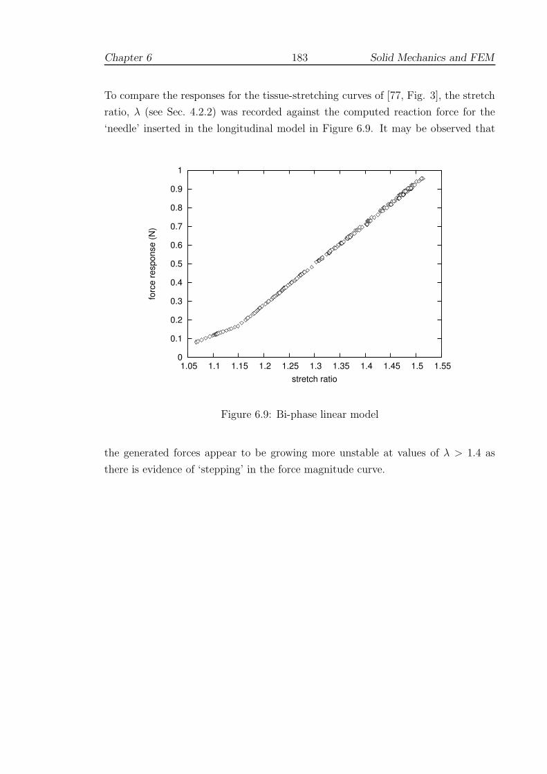
Chapter 6 183 Solid Mechanics and FEM
To compare the responses for the tissue-stretching curves of [77, Fig. 3], the stretch
ratio, λ (see Sec. 4.2.2) was recorded against the computed reaction force for the
‘needle’ inserted in the longitudinal model in Figure 6.9. It may be observed that
0
0.1
0.2
0.3
0.4
0.5
0.6
0.7
0.8
0.9
1
1.05 1.1 1.15 1.2 1.25 1.3 1.35 1.4 1.45 1.5 1.55
forc
e re
spon
se (N
)
stretch ratio
Figure 6.9: Bi-phase linear model
the generated forces appear to be growing more unstable at values of λ > 1.4 as
there is evidence of ‘stepping’ in the force magnitude curve.

Chapter 7
Evaluation
The chapter describes three attempts to evaluate the FESTIVALS system
(Section 7.1). The methodology and results of each test are presented in
Sections 7.2–7.4. The final section (7.5) discusses the results of these findings
as a whole.
‘I wear the chain I forged in life, replied the Ghost. I made it link by
link, and yard by yard; I girded it on of my own free will, and of my own
free will I wore it. Is its pattern strange to you? ’
- Charles Dickens, A Christmas Carol (1843)
7.1 Overview
7.1.1 Training premise
In Chapter 2, it was observed that many evaluations were targeted towards improv-
ing the assessment of trainees, in order to demonstrate that the tests held construct
validity. Whilst this property is important, it was argued that testing experts against
novices provides only a weak test of the system, and, more importantly, does not
give adequate consideration to the issues of transfer and retention. Furthermore, it
appeared that many VR simulators added little more than clocking facilities to ex-
184

Chapter 7 185 Evaluation
isting tools, so that the potential for VR to provide a stronger training environment
was not being evaluated.
7.1.2 Refining the research hypothesis
In Section 1.4.3, the following research hypothesis was adopted:-
Training using a virtual suturing simulator can improve real-world
performance.
For evaluation, the approach taken was to test a set of simpler sub-hypotheses
(HA − HC). These were aimed at basic properties of skill acquisition, namely that:
HA: performance should display a learning curve with improvement in terms
of error reduction, consistency and persistency;
HB: performance on the simulator should produce improvement using real-
world tools;
HC : performance should not violate the property of construct validity as
stated: in particular, experts should not find the system more difficult
to use than trainees.
7.1.3 Metrics
Whilst efficient movement is of interest, and ‘time taken’ and ‘distance moved’ are
often the only metrics to show significant differences between experts and novices,
it may be that these differences simply affirm the principle of the ‘power law of
practice’. In other words, repeated practice seems to lead to natural efficiency of
movement, whether or not the technique has been mastered. In particular, there
may be a trade-off between speed and accuracy (3.5.5.2) and it is therefore vital to
monitor errors in addition to time etc. The metrics under test here are therefore
based mainly upon the feedback schedule for the FESTIVALS system described in
Section 5.3.8. In particular, these may be listed as:
• Angular difference between entry and exit planes;
• Strike angle error
• Needle plane to edge direction error;
Chapter 7 186 Evaluation
• Needle centre variation and difference during entry and exit;
• Movement of the needle centre ‘out of plane’ (principal components analysis);
• Time taken and total displacement during the insertion/retrieval of the needle;
• Total stitch and inter-stitch time.
All participants completed a standard questionnaire for each test, which is described
in Section 7.4. Despite the use of specific forms of feedback during development,
no form of overall score was generated. This was intended to avoid any possible
demotivational aspects of scoring (if, say, scores appear to get worse for a time) and
to avoid pressing participants to speed up. Also, it was hoped that using the output
from these tests, a more considered scoring procedure could be created.
7.1.4 Statistical evaluation
Several problems relating to the statistical evaluation of simulators have been de-
scribed, especially in the use of contrasts between expert and novice performances
(see 3.6). A further problem arises, however, with attempts to use general linear
analysis of variance (ANOVA) models (eg. O’Toole et al, Crossan — see 2.4.2.2 and
2.4.3.3 [119, 307]) in that these models do not cope well with non-random effects.
In particular, it is important to evaluate the property known as sphericity in data.
Repeated measures (or within subjects) ANOVA is an attractive and powerful
statistical model since the need for control groups is removed and relatively few
subjects are required, as differences between subjects are ignored [250]. In fact, the
method relies upon three sources of variability: treatment, individual changes and
random/residual. An important assumption of this procedure, known as sphericity,
is that a random factor which causes variation in one subject’s measurement to
be high (or low) at any point in time should not cause fixed effects in the next
reading taken. Failure to correct for violations of sphericity can lead to low p-
values, and hence Type I error. Many texts advise the use of cross-over designs,
and lengthy periods between measurements to allow any fixed effects to be ‘washed
out’ [13]. Several tests for sphericity (eg. using covariance) have been proposed
[44, 155, 156, 198], but to the authors’ knowledge, where ANOVA tests have been
used in simulator evaluation, these tests (or corrections) are absent.
Directed learning is certainly affected by factors such as age, sex and handed-
ness [364]. If other factors could be assumed to be random, or could be as easily
Chapter 7 187 Evaluation
screened out, it would be tempting to suppose that the issue of sphericity could be
ignored. It seems likely, though, that there may be many such confounding factors:
fatigue, personal confidence, adaptation to the interface, environmental conditions
etc. Corrections for sphericity generally involve a process of reducing dof, so that
the p-values generated are less significant [44, 198]. Critics point out, however, that
this is really an abuse of the random effects model [J. Lindsey, personal communi-
cation, October 2004] and more specific learning models are usually preferred, such
as Markov chains [258]. In game theory, still more sophisticated models have been
adopted, such as those related to equilibria [87, 403].
Given the early stage of development and limited data sets, more basic t-tests
would seem to be preferable. Using t-tests, the problem of sphericity is avoided,
albeit with possible loss of statistical power. There is, however, a further problem
when comparing the means of many different levels of a factor. Multiple comparisons
using t-tests tends to inflate the probability of declaring a significant difference when
it is not in fact present1. There are numerous post-hoc methods to correct for this
situation in ANOVA eg. Tukey’s Honestly Significant Difference (HSD) method,
which is the approach adopted by Crossan (see 2.4.2.2). With these provisos in
mind, the reader should be aware that most statistical comparisons will be limited.
They are offered mainly for qualitative discussion.
7.2 Test A: Learning curve and retention
7.2.1 Introduction
Previous research has shown that many surgical procedures have steep initial learn-
ing curves during which patients would appear to be at considerable risk (Section
3.1). With few notable exceptions, learning curves have rarely been investigated for
surgical simulators. Preliminary studies have been undertaken for MIST (Chaudhry
et al [95], Grantcharov et al [187]; see 2.3.2.1) and for the BDI simulator (Murray
et al [291]; see 2.4.3.3). In Sections 2.5 and 3.6.1, however, it was argued that the
failure to appreciate learning curves was a major cause of difficulty with respect to
obtaining reliable estimates of validity.
1Because the intervals are calculated with a given coverage probability for each interval but theinterpretation of the coverage is usually with respect to the entire family of intervals [323]

Chapter 7 188 Evaluation
7.2.2 Objectives
To study the learning curve of the FESTIVALS prototype simulator, this test focuses
on the insertion and retrieval phase of each suture since these are most closely
associated with the essential curving action described in Section 5.1.1.1. The main
aims of this test were:
• To chart the improvement, consistency and persistency of a single suturing
technique with extended practice;
• To determine possible plateaux or asymptotic levels of performance.
It should be noted that Cuschieri’s claim that ‘Some surgeons will immediately rise
to a level of proficiency. . . ’ (2.2.1.1) is specifically being rejected here. Learning
curves are complex abstractions which tend to show anything but a straightforward
progression — it is ‘consistency that counts’ [40].
7.2.3 Method
Participants
Due to the time commitment required by repeated practice to build the learning
curve, only one subject was recruited. This was a surgically naive subject (age 40,
female, right-handed), with no experience of VR.
Task
The task was of a fairly simple format in which the dominant hand was used ex-
clusively with the half-cylinder model of Figure 5.16. Suturing was performed in a
forehand (insert) and overhand (regrab) pattern — see Figure 5.12 (a) and (e) —
targeting the red beads placed at a depth of 2 mm along the edge of the ‘wound’.
This action suits the capabilities of the equipment very well (see Discussion), but
also provides a more difficult test of skill than the more usual forehand technique.
Schedule
The subject undertook a practice schedule of one-hourly sessions for six days. Prac-
tice and 3-minute test trials were interspersed according to the participant’s wishes,
with four or more trials being completed on each day. In total 43 successful trials

Chapter 7 189 Evaluation
were completed; data from 5 tests had to be abandoned due to sensitivities or tech-
nical problems with the equipment. The needle holder was attached by ties/tape to
the PHANToM as in Figure 5.9.
A retention test of four trials was carried out during a further one-hour session
undertaken approximately 6 weeks (40 days) later.
Analysis
The data were analysed and plotted using the GNU/Linux statistical packages ‘R’
(v.2.0.0) [323] and Gnuplot (v.4.0) [450]. SPSS (v.12.0.1) for Windows was used for
some statistical analyses [3].
7.2.4 Results
7.2.4.1 Errors during insertion and retrieval of the needle
This section presents a number of plots which focus on the insertion and retrieval
phase of each completed suture, averaged over each 3-minute trial. Given the difficul-
ties described above (7.1.4), discussion of statistical significance is generally avoided
until Section 7.2.5.
1. Plane angular error
• The curved shape of the needle defines a plane, which is defined math-
ematically by a normal (and a point in the plane). The average normal
during the insertion and retrieval phases was used to compute the re-
spective entry and exit planes, as shown in Figure 5.16. The angular
difference between these average planes is defined as plane angular error.
• The ‘box-and-whisker’ plot of Figure 7.1 displays the distribution of this
error for trials (3-minute tests) over the training and retention phases.
The parameters of these plots have been set so that the central ‘hinge’
indicates the median and interquartile range of the variable of inter-
est, whilst the outer ‘whiskers’ indicate the most extreme data points.
• It can be seen that the initial performance shows a wide range of varia-
tion between adjacent trials, although the median value is predominantly
above 20◦. The median position is also often skewed, indicating a skewed
distribution, but the direction of this skew does not seem to follow any
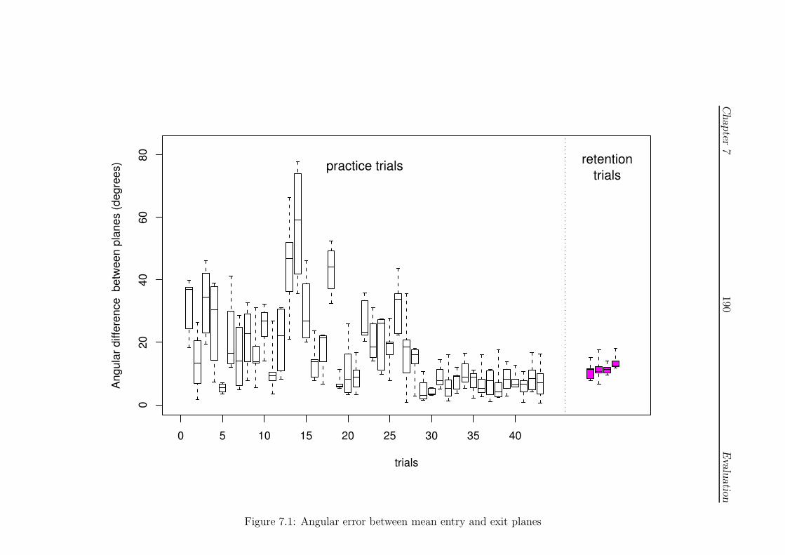
Chapter
7190
Evalu
atio
n
0 5 10 15 20 25 30 35 40
020
4060
80
trials
Angu
lar d
iffer
ence
bet
ween
pla
nes
(deg
rees
) practice trials retentiontrials
Figure 7.1: Angular error between mean entry and exit planes
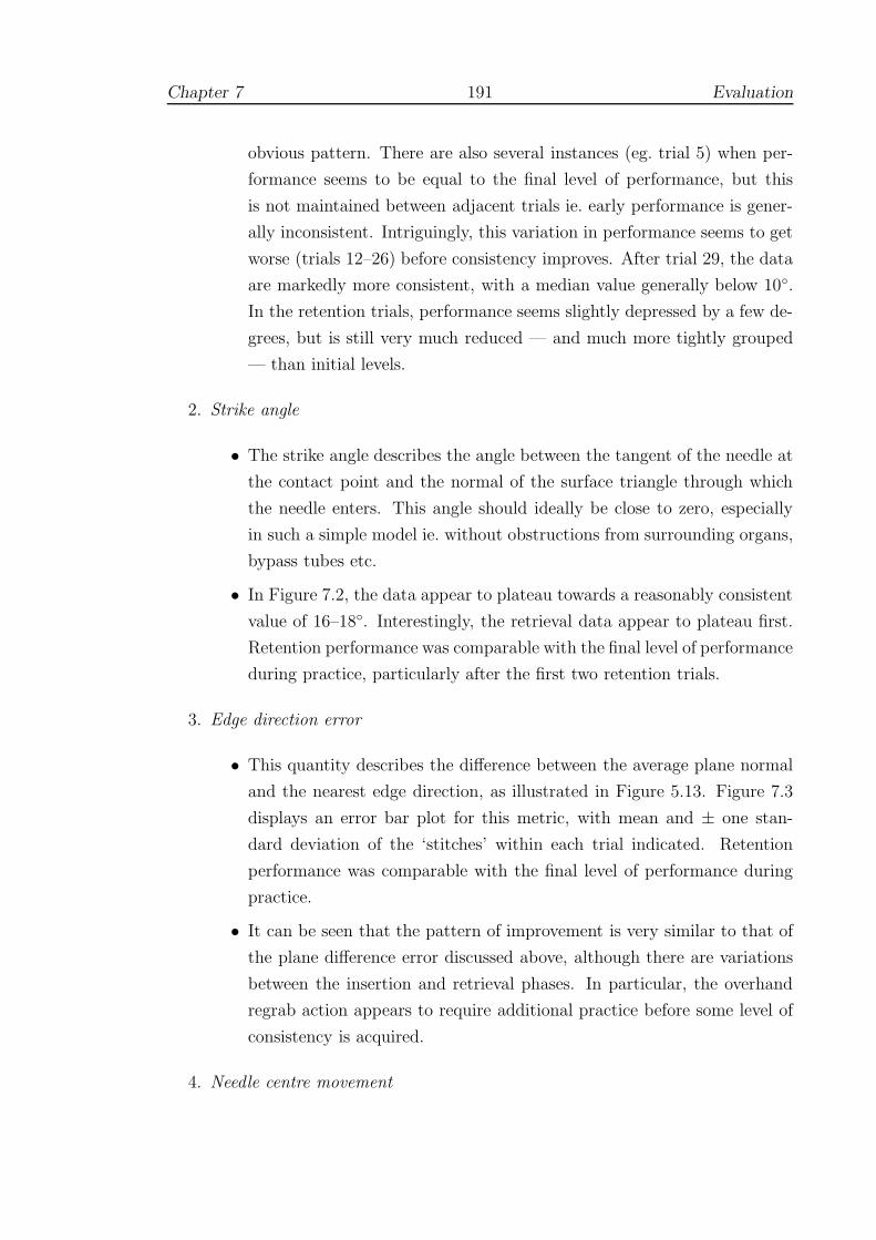
Chapter 7 191 Evaluation
obvious pattern. There are also several instances (eg. trial 5) when per-
formance seems to be equal to the final level of performance, but this
is not maintained between adjacent trials ie. early performance is gener-
ally inconsistent. Intriguingly, this variation in performance seems to get
worse (trials 12–26) before consistency improves. After trial 29, the data
are markedly more consistent, with a median value generally below 10◦.
In the retention trials, performance seems slightly depressed by a few de-
grees, but is still very much reduced — and much more tightly grouped
— than initial levels.
2. Strike angle
• The strike angle describes the angle between the tangent of the needle at
the contact point and the normal of the surface triangle through which
the needle enters. This angle should ideally be close to zero, especially
in such a simple model ie. without obstructions from surrounding organs,
bypass tubes etc.
• In Figure 7.2, the data appear to plateau towards a reasonably consistent
value of 16–18◦. Interestingly, the retrieval data appear to plateau first.
Retention performance was comparable with the final level of performance
during practice, particularly after the first two retention trials.
3. Edge direction error
• This quantity describes the difference between the average plane normal
and the nearest edge direction, as illustrated in Figure 5.13. Figure 7.3
displays an error bar plot for this metric, with mean and ± one stan-
dard deviation of the ‘stitches’ within each trial indicated. Retention
performance was comparable with the final level of performance during
practice.
• It can be seen that the pattern of improvement is very similar to that of
the plane difference error discussed above, although there are variations
between the insertion and retrieval phases. In particular, the overhand
regrab action appears to require additional practice before some level of
consistency is acquired.
4. Needle centre movement

Chapter
7192
Evalu
atio
n
Strike angle (degrees)
0 10 20 30 40 50 600 10 20 30 40 50 60
insertion−phasepractice trials
retentiontrials
0 10 20 30 40 50 600 10 20 30 40 50 60
010
2030
40
0 10 20 30 40 50 60
retrieval−phase
trials
Figu
re7.2:
Strike
angle
error

Chapter
7193
Evalu
atio
n
Edge direction (degrees)
0 10 20 30 40 50 600 10 20 30 40 50 60
insertion−phasepractice trials
retentiontrials
0 10 20 30 40 50 600 10 20 30 40 50 60
010
2030
40
0 10 20 30 40 50 60
retrieval−phase
trials
Figu
re7.3:
Edge
direction
error
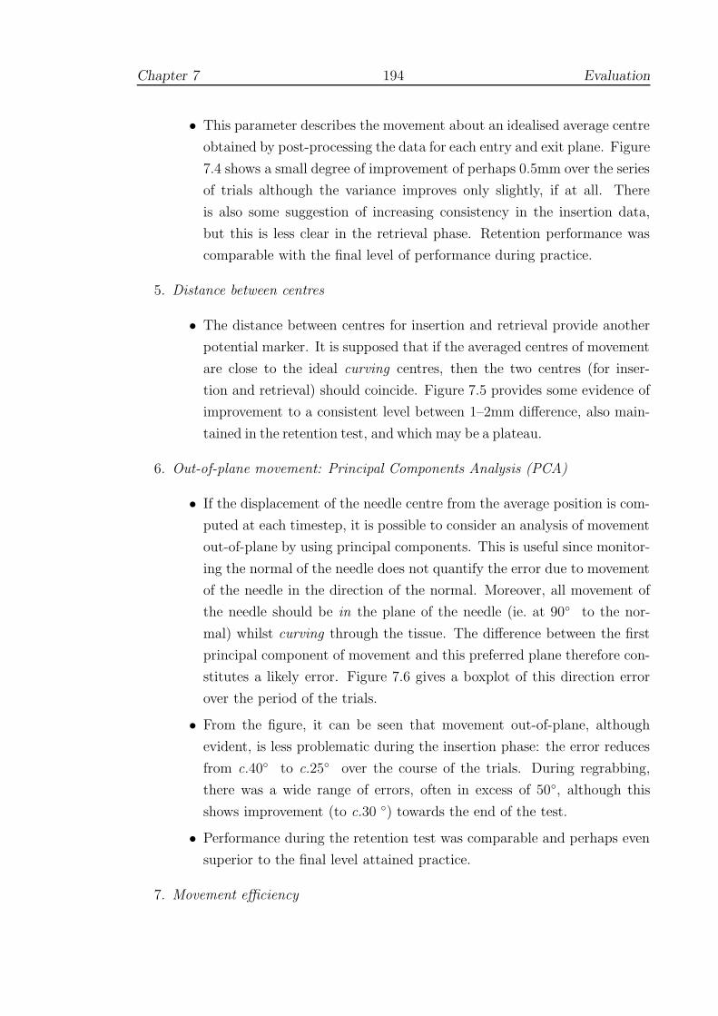
Chapter 7 194 Evaluation
• This parameter describes the movement about an idealised average centre
obtained by post-processing the data for each entry and exit plane. Figure
7.4 shows a small degree of improvement of perhaps 0.5mm over the series
of trials although the variance improves only slightly, if at all. There
is also some suggestion of increasing consistency in the insertion data,
but this is less clear in the retrieval phase. Retention performance was
comparable with the final level of performance during practice.
5. Distance between centres
• The distance between centres for insertion and retrieval provide another
potential marker. It is supposed that if the averaged centres of movement
are close to the ideal curving centres, then the two centres (for inser-
tion and retrieval) should coincide. Figure 7.5 provides some evidence of
improvement to a consistent level between 1–2mm difference, also main-
tained in the retention test, and which may be a plateau.
6. Out-of-plane movement: Principal Components Analysis (PCA)
• If the displacement of the needle centre from the average position is com-
puted at each timestep, it is possible to consider an analysis of movement
out-of-plane by using principal components. This is useful since monitor-
ing the normal of the needle does not quantify the error due to movement
of the needle in the direction of the normal. Moreover, all movement of
the needle should be in the plane of the needle (ie. at 90◦ to the nor-
mal) whilst curving through the tissue. The difference between the first
principal component of movement and this preferred plane therefore con-
stitutes a likely error. Figure 7.6 gives a boxplot of this direction error
over the period of the trials.
• From the figure, it can be seen that movement out-of-plane, although
evident, is less problematic during the insertion phase: the error reduces
from c.40◦ to c.25◦ over the course of the trials. During regrabbing,
there was a wide range of errors, often in excess of 50◦, although this
shows improvement (to c.30 ◦) towards the end of the test.
• Performance during the retention test was comparable and perhaps even
superior to the final level attained practice.
7. Movement efficiency
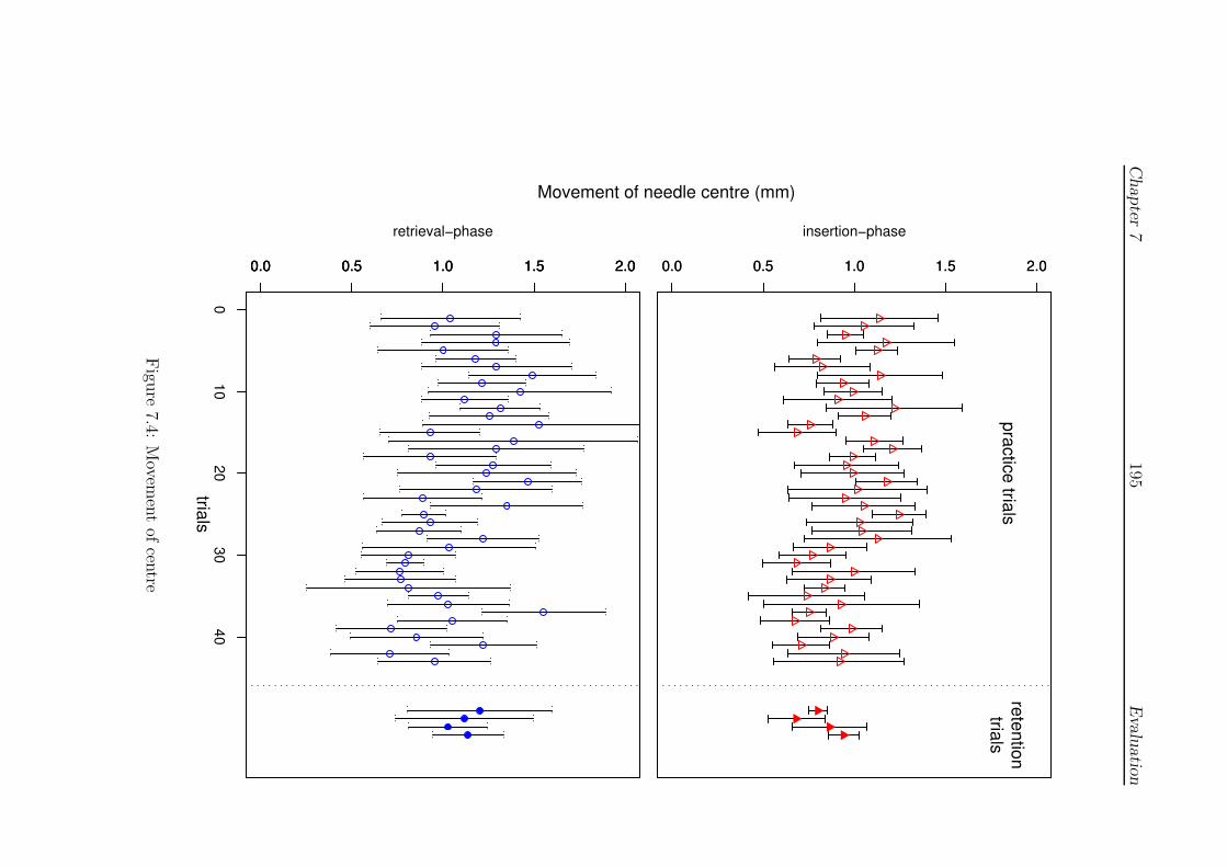
Chapter
7195
Evalu
atio
n
Movement of needle centre (mm)
0.0 0.5 1.0 1.5 2.00.0 0.5 1.0 1.5 2.0
insertion−phasepractice trials
retentiontrials
0.0 0.5 1.0 1.5 2.00.0 0.5 1.0 1.5 2.0
010
2030
40
0.0 0.5 1.0 1.5 2.0
retrieval−phase
trials
Figu
re7.4:
Movem
ent
ofcen
tre
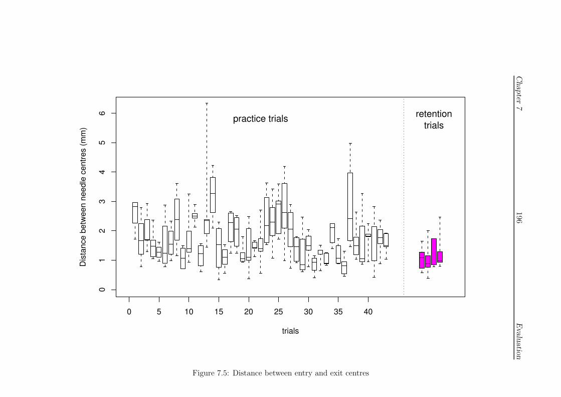
Chapter
7196
Evalu
atio
n
0 5 10 15 20 25 30 35 40
01
23
45
6
trials
Dist
ance
bet
ween
nee
dle
cent
res
(mm
)
practice trials retentiontrials
Figure 7.5: Distance between entry and exit centres
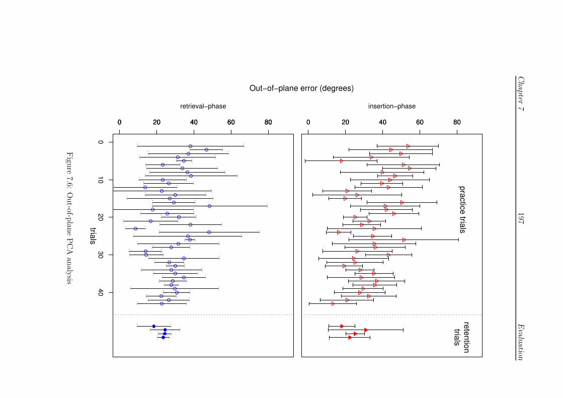
Chapter
7197
Evalu
atio
n
Out−of−plane error (degrees)
0 20 40 60 800 20 40 60 80
insertion−phasepractice trials
retentiontrials
0 20 40 60 800 20 40 60 80
010
2030
40
0 20 40 60 80
retrieval−phase
trials
Figu
re7.6:
Out-of-p
lane
PC
Aan
alysis

Chapter 7 198 Evaluation
• Figures 7.7 and 7.8 show the total time and displacement during the in-
sertion and retrieval phases. This data also shows an increasing tendency
towards consistency in the later trials, although the trajectories displayed
in the figures are divergent, at least in the centre of the chart (trials 12–
33). It is particularly interesting to note that this portion of the curve
appears to show that retrieval action is being more quickly completed,
whilst it is clear from the preceding error plots (Figures 7.3 and 7.4 espe-
cially) that this action was the most error prone during period (ie. speed
may have been contributing to the error). This suggests that the subject
was struggling with different aspects of the task during different stages
and speed had to be reduced to make progress in the more difficult phases.
0
2
4
6
8
10
12
0 10 20 30 40 50
time
(s)
trials
practice trials/insertionpractice trials/retrieval
retention trials/insertionretention trials/retrieval
Figure 7.7: Timing of insertion/regrab phases
7.2.4.2 Total time and inter-stitch time
The focus of the present study was not time-orientated ie. the task was chosen to
be of sufficient complexity, and feedback was given, such that complete mastery or
proficiency was not expected. Since many studies have focused upon this element,
however, it seems appropriate to provide some form of comparison here. The study

Chapter 7 199 Evaluation
10
15
20
25
30
35
40
0 10 20 30 40 50
tota
l disp
lace
men
t (m
m)
trials
practice trials/insertionpractice trials/retrieval
retention trials/insertionretention trials/retrieval
Figure 7.8: Travel during insertion/regrab phases
by Moody et al (see 2.4.3.4), in particular, suggested that novices showed exagger-
ated periods of time between stitches (at rest, setting the needle etc.) which was
denoted as the ‘inter-stitch’ time.
Figure 7.9 present an error bar comparison of the total stitch and inter-stitch
time by trial. A small, non-significant degree of improvement is suggested but a
strong correlation between the inter-stitch and total stitch time is present (Pearson’s
r2 = 0.680, p < 0.001). It is argued that the data support the view that technical
skills were still being acquired and that only a moderate degree of proficiency was
achieved.
7.2.5 Performance statistics
Using the empirical observation of 7.2.4(1) that practice trials appear to comprise
three phases (I-III), and describing the retention test as phase IV, Table 7.1 shows
the significance (p-)values obtained by applying Welch two-sample t-tests over each
‘stitch’ between phases:
1. I–II (trials 1–11 and 12–28),
2. II–III (trials 12–28 and 29–43),
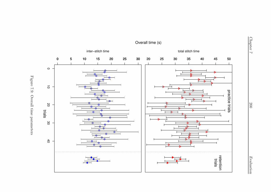
Chapter
7200
Evalu
atio
n
Overall time (s)
20 25 30 35 40 45 5020 25 30 35 40 45 50
total stitch time
practice trials
retentiontrials
0 5 10 15 20 25 300 5 10 15 20 25 30
010
2030
40
0 5 10 15 20 25 30
inter−stitch time
trials
Figu
re7.9:
Overall
time
param
eters

Chapter 7 201 Evaluation
3. III–IV (trials 29–43 and retention),
4. I–IV (trials 1–11 and retention).
Evidence for the choice of categories used in Table 7.1 was not unequivocal
although they were relatively broad to emphasise most distinct changes, ie. with
less chance of obtaining significance by accident. All rows contain some evidence
of significant changes at least at the p < 0.05 level, supporting the view that the
chosen metrics were appropriate for study. More surprising, however, is that the
table suggests that the largest change occurred between phases II–III, underlining
the more consistent nature of the results during the final practice trials (which may
be reaching asymptote). The difference between the initial (phase I) and retention
trials is similarly marked, with the notable exception of the results for the striking
angle. It should be noted that the difference between phases I and III (not shown)
was significant at the p < 0.05 level, suggesting some loss of performance during the
retention tests.
Two further observations may be made: (i) the table shows improvements during
many separate phases (even in the retention trials for the out-of-plane error); and
(ii) visually at least, Figures 7.1–7.9 appear to show cycles of improvement, which
suggests that random effects models are inappropriate (ie. that the data appears to
violate the sphericity assumption). In the absence of a clearer learning model, how-
ever, it is suggested that the daily schedule of practice, which is roughly comparable
to the phases indicated (phase I ≈ days 1–2, etc.) may be a source of variation (as
was also the case for the microsurgery data 3.1.2).
To examine this effect whilst reducing the potential for false positive significant
differences, the plane angular error data were reanalysed using a one-way ANOVA
model (without correction) factored by day, with post-hoc Tukey HSD analysis.
Differences between the ‘family’ of means (ie. between all the means for each day,
with the retention test at ‘day 7’) are shown in Figure 7.10. The figure displays the
confidence interval (to the p < 0.05 level) for differences between these means and is
significant where zero difference between means is not contained within the interval.
Qualitatively at least, the figure shows that central phase of practice (ie. phase II)
appears to be distinguished whilst the retention results are comparable to the final
level of practice performance.
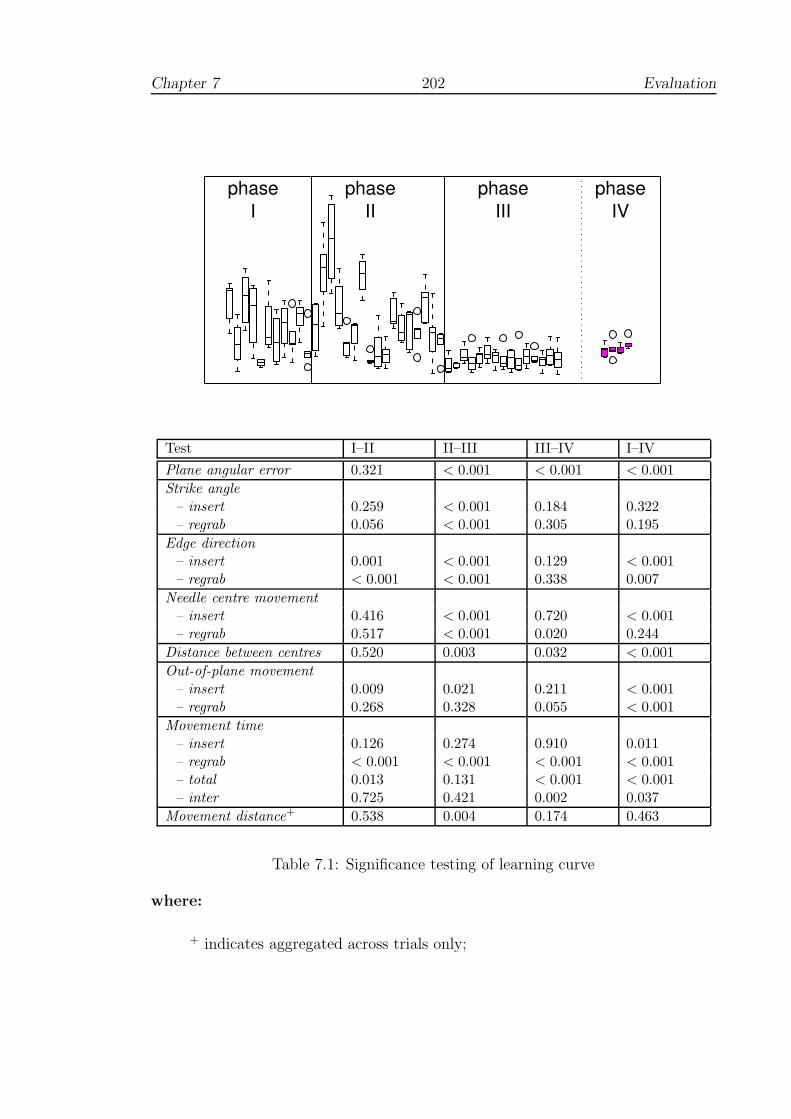
Chapter 7 202 Evaluation
phaseI
phaseII
phaseIII
phaseIV
Test I–II II–III III–IV I–IV
Plane angular error 0.321 < 0.001 < 0.001 < 0.001
Strike angle
– insert 0.259 < 0.001 0.184 0.322– regrab 0.056 < 0.001 0.305 0.195
Edge direction
– insert 0.001 < 0.001 0.129 < 0.001– regrab < 0.001 < 0.001 0.338 0.007
Needle centre movement
– insert 0.416 < 0.001 0.720 < 0.001– regrab 0.517 < 0.001 0.020 0.244
Distance between centres 0.520 0.003 0.032 < 0.001
Out-of-plane movement
– insert 0.009 0.021 0.211 < 0.001– regrab 0.268 0.328 0.055 < 0.001
Movement time
– insert 0.126 0.274 0.910 0.011– regrab < 0.001 < 0.001 < 0.001 < 0.001– total 0.013 0.131 < 0.001 < 0.001– inter 0.725 0.421 0.002 0.037
Movement distance+ 0.538 0.004 0.174 0.463
Table 7.1: Significance testing of learning curve
where:
+ indicates aggregated across trials only;
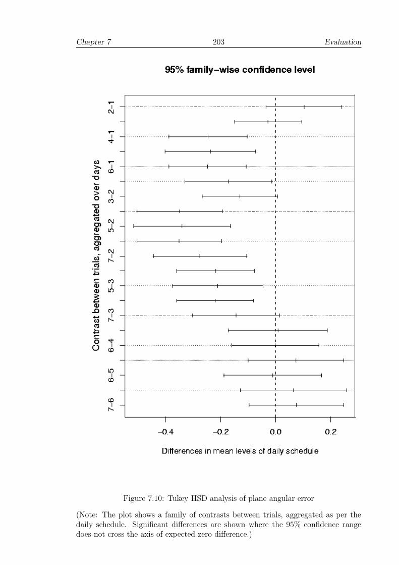
Chapter 7 203 Evaluation
Figure 7.10: Tukey HSD analysis of plane angular error
(Note: The plot shows a family of contrasts between trials, aggregated as per thedaily schedule. Significant differences are shown where the 95% confidence rangedoes not cross the axis of expected zero difference.)
Chapter 7 204 Evaluation
7.2.6 Comments
The subject completed a questionnaire, the results of which are included in Table 7.3
below. A number of useful comments were also added, which are condensed below:
• The main improvement seemed to occur early on, after growing more confident
for the equipment.
• Even towards the end of the test, it was hard to deal with targeting/overshoot
problem even with 3D stereo; it was necessary to keep probing tissue to find
the actual working depth.
• The device was physically heavy and made the hand quite sore after an hour’s
use.
• Rotation of the wrist through such large angles felt rather forced, despite
assurances that these were really required.
The interface seems to be the main issue here, and possible influences that this may
have had upon the test. Perhaps the most serious is the problem of assessing depth,
since it is less easy to see how this difficulty might be improved upon — see Section
7.5 for further discussion.
7.3 Test B: Using real tools
7.3.1 Introduction
This test was intended to provide a direct comparison of the VR simulator with a
test using real suturing tools within a synthetic medium. By using a control group,
it was hoped that some of the problems of sphericity, described in Section 7.1.4,
would be bypassed. This study was of limited size, however, given health and safety
requirements, which are described below.
7.3.2 Objectives
To identify potential improvements in the use of real surgical tools after a period
of training on the FESTIVALS prototype. This test is therefore an attempt to
assess the concurrent validity of the simulator by comparison with an appropriate
standard.
Chapter 7 205 Evaluation
7.3.3 Method
Participants
Six surgically naive members of the School of Computing (male, age 35.5±12.6 years
(mean±1 sd), two left-handed) volunteered to participate in the test. They were
divided into experimental and control groups based upon availability with respect
to the task schedule. The voluntary basis of the test had three important restrictive
effects: (i) the experimental group contained both left-handed subjects; (ii) the
number of training sessions was much more limited than for the learning curve test
(Test A); and (iii) the age range of the participants was broader than desirable
(youngest 22, oldest 57). All participants had experience of VR devices, but none
had any extensive or recent experience of the VR task.
Tools and safety
Tools and synthetic skin-pads were provided by the Suture Tutor Kit (5.1.1.2). For
safety purposes a risk assessment was compiled by the author (included in Appendix
C), which emphasised the nature of the task and correct holding positions for tweez-
ers, scalpel and needles. It should be noted that due to the use of surgical needles,
and limited facilities in the School of Computing for handling sharps, it was not
desirable to involve greater numbers of participants.
Task
The test task was modelled on the surface wound problem represented by the skin-
pad, see Figures 5.2 and 7.11 (and further details in the risk assessment) and was
based on the ‘mattress’ suture technique. One stitch therefore comprises two fore-
hand, and then two backhand suture actions (see Figure 5.12). This requires that
the needle is retrieved from the base of the wound at intermediate points. Knot-
tying was not practiced, however, and the participants were required to continue
suturing, effectively in a ‘zig-zag’ path. It was supposed that training would im-
prove the quality of the sutures in terms of even spacing, width and symmetry (see
Moody et al, Section 2.4.3.4).
Pre- and post-tests comprised 10 minutes’ suturing, the results being captured
by video camera and by scanned/digitised images of the completed pads (eg. Figure
7.12). For the VR training component, the FESTIVALS simulator was used with a
block type model to mirror the task on the skin-pad, with alternate practice attempts

Chapter 7 206 Evaluation
Figure 7.11: Using the Suture Tutor Kit
(from [20])
Figure 7.12: Skin-pad, pre- and post-test
Chapter 7 207 Evaluation
at forehand and backhand motions in groups of 5 stitches. Training periods lasted
approximately 45 minutes.
Schedule
The schedule was similar to that used to obtain the sample learning curve, so that
block training effects were avoided, participants had time to rest and the practice
effect of the skin-pad test were minimised. The test schedule is given in Table 7.2.
Day Control group Experimental group
1 Skin-pad test Skin-pad test2 - VR practice3 - VR practice4 Skin-pad test Skin-pad test
Table 7.2: Schedule of the skin-pad test
Analysis
Timing data from the skin-pad tests were obtained manually from video frame
counter. Suture path data were digitised from the scanned images of the pads
using Corel Draw (v.7) [7] and corrected so that the main axis of the ‘wound’ was
vertical before output with AutoCAD R.12 [6]. The path of the sutures was plotted
for each subject, to examine spacing and symmetry.
7.3.4 Results
7.3.4.1 Synthetic pad data
The output of the scanned suturing blocks, with the direction of working adjusted
to that shown, is given in Figure 7.13. The plot shows considerable variation in
the visible suture pattern and it is difficult to identify clear criteria for describing
symmetry, especially by a single index. Area to either side of the wound-line, for
example, may work well in most situations but would perform poorly if the trans-
formation from the desired ‘box’ shape was affine (eg. a shear). Also, even if such
an index could be found, it would not be expected to reflect the situation within the
‘wound’. Two indices were chosen: (i) angular deviations from the path (or trans-
verse) of the wound-line; and (ii) the difference in length between opposite sides of
each suture.
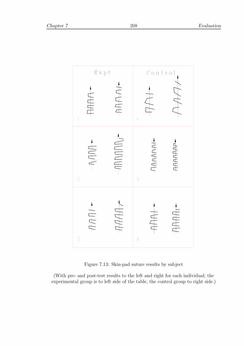
Chapter 7 208 Evaluation
Figure 7.13: Skin-pad suture results by subject
(With pre- and post-test results to the left and right for each individual; theexperimental group is to left side of the table, the control group to right side.)

Chapter 7 209 Evaluation
The data for both groups were analysed by linear ANOVA using the data col-
lected from the completed stitches. Analysis of total and inter-stitch time against
test (ie. pre-test and post-test) and group (experimental or control) revealed a sig-
nificant effect for test p < 0.05, indicating a strong practice effect for both groups,
but a non-significant group or group/test interaction effect. However, if the strongly
outlying data from individual ‘4’ (Figure 7.13) are omitted, this leaves a more co-
herent picture (5 participants, age 31.6±7.7 years, age range 22–39 years) with a
non-significant but stronger group effect for time taken per stitch with p = 0.096.
Similarly, the angular symmetry parameter approaches significance when factored
by group, with p = 0.071.
Using the variances obtained for total stitch time here, the ‘R’ package gives an
estimate for the statistical power of this test at just over 10%. This implies that
even if the simulator was established as an effective training tool, this test would
only have given significant results in 1 out of 10 applications. Furthermore, to set
the power of the test at 80% (a figure quoted as desirable in many texts), would have
required 34 people in both the control and experimental groups. Hence, whilst these
results are insignificant by convention, it is suggested that the significance values
are of some interest (see 7.5.2).
7.3.4.2 VR data
Since the primary objective of this test was to assess performance with real tools,
detailed analysis of performance on the simulator is not considered relevant. For
comparison with the results above, however, Figure 7.14 presents a graph of mean
stitch time data for the experimental group. In general, it can be seen that timing
data appear to be improving and converging although for some aspects, performance
for two individuals decreased. Performance does not, therefore, appear to have
reached a level of consistency (which would not be expected, given the results of the
learning curve test, above).
7.3.5 Comments
The experimental group made several useful comments about the VR system:
• Most participants felt more assured during post-test, although they did not
generally feel that they had mastered the technique;
• The forces exhibited by the simulator felt weak sometimes;

Chapter 7 210 Evaluation
20
30
40
50
60
70
80
90
-0.5 0 0.5 1 1.5
mea
n to
tal s
titch
tim
e (s
)
VR training days
Subject 1/forehandSubject 1/backhandSubject 2/forehand
Subject 2/backhandSubject 3/forehand
Subject 3/backhand
Figure 7.14: Mean stitch time in the simulator
• Some feedback relating to time taken would have been helpful, relating to the
most error-prone region of the suturing action;
• Piercing the mesh seemed to get more difficult through practice and this prob-
lem was not overcome during the test;
• The exit point seemed to be difficult to predict or correct from the path an-
ticipated at entry;
Many of the points raised here seem to be related to insufficient time spent in
practice — most appeared to feel that, despite some level of improvement, they had
not mastered the technique. See Section 7.5 for further discussion.
7.4 Test C: Usability study
7.4.1 Introduction
It was originally intended that this study should comprise a quasi-transfer and reten-
tion test of surgical trainees, taking place over 3–4 sessions. Although, initially, this
was thought to be feasible entirely on a voluntary basis, in practice, the demands
of surgery schedules prevented its completion. To complement the transfer study,
however, a more qualitative study by questionnaire was proposed, to be updated
after each session. The introductory session was intended to be fairly informal and
allow people to get used to the equipment. Forces were deliberately set to be fairly

Chapter 7 211 Evaluation
weak, with the bi-phase model generating greater forces after a modest displacement
(3 mm), so that users would be less likely to be daunted, especially if the capacity
of the system was exceeded. All participants had a brief explanation of the task and
how to use the apparatus to start trials, set the needle etc.
7.4.2 Objectives
Since it did not prove to be possible to obtain repeat tests, the primary aim of
the study was to obtain a qualitative assessment of the FESTIVALS system by
clinicians. Since data was obtained across a range of expertise, however, it was also
possible to obtain statistics for general comparison across the groups and the tests
above.
7.4.3 Method
Participants
15 clinicians, from various disciplines, participated in the test — conducted at St
James’ Hospital, Leeds — on a voluntary basis. Of these, 12 returned completed
questionnaires. Data were only excluded from one of the non-returning participants,
however, since groups for the others were able to be determined later. The partici-
pants therefore comprised:
• Surgical:
– 6 trainees/SHOs, in the 3rd/4th year of rotation (5 males, 1 female; age:
25.5±1.7 years);
– 2 specialist registrars (SpR year 6, both male; both age: 37 );
– 2 vascular consultants (both male; both age: 46);
• Microsurgical:
– 1 consultant (male; age: 58)
• Non-surgical:
– 3 consultant radiologists (male; age: 48.5±6.3 years)
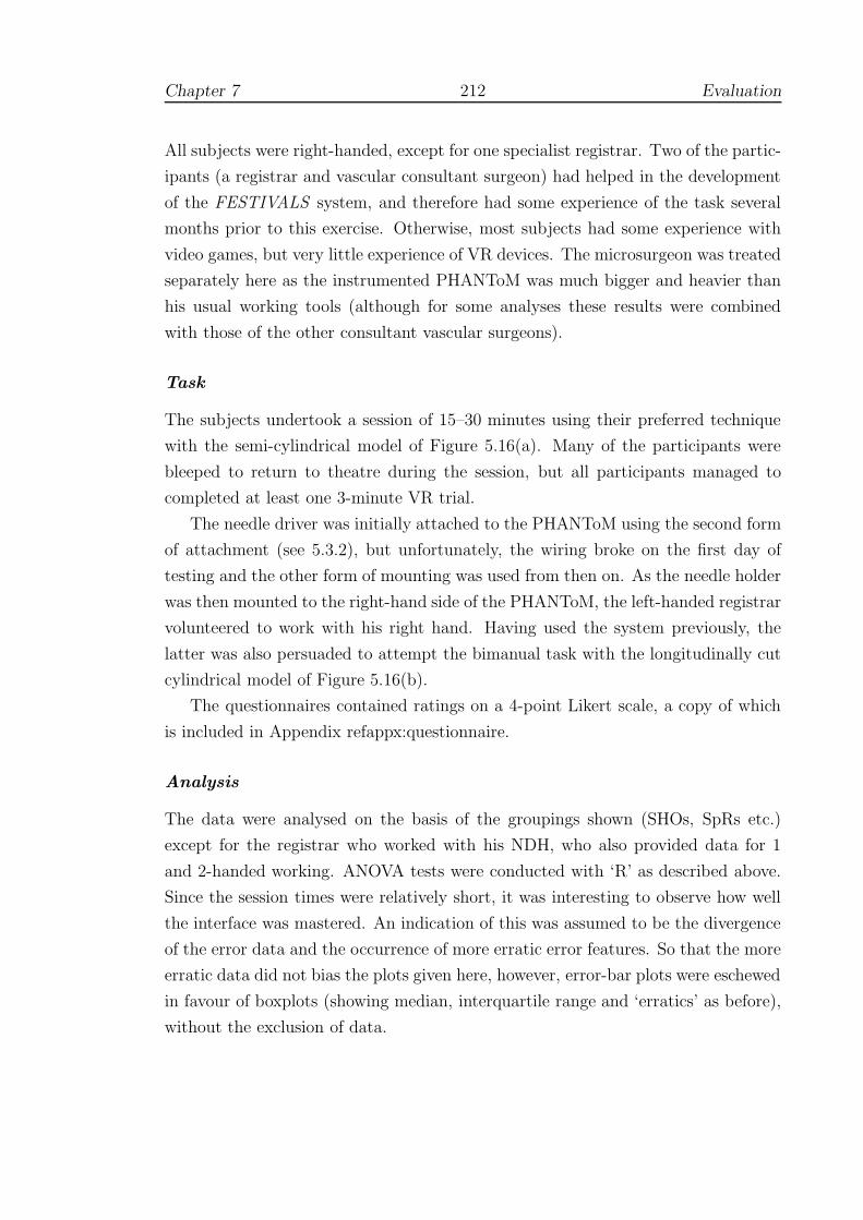
Chapter 7 212 Evaluation
All subjects were right-handed, except for one specialist registrar. Two of the partic-
ipants (a registrar and vascular consultant surgeon) had helped in the development
of the FESTIVALS system, and therefore had some experience of the task several
months prior to this exercise. Otherwise, most subjects had some experience with
video games, but very little experience of VR devices. The microsurgeon was treated
separately here as the instrumented PHANToM was much bigger and heavier than
his usual working tools (although for some analyses these results were combined
with those of the other consultant vascular surgeons).
Task
The subjects undertook a session of 15–30 minutes using their preferred technique
with the semi-cylindrical model of Figure 5.16(a). Many of the participants were
bleeped to return to theatre during the session, but all participants managed to
completed at least one 3-minute VR trial.
The needle driver was initially attached to the PHANToM using the second form
of attachment (see 5.3.2), but unfortunately, the wiring broke on the first day of
testing and the other form of mounting was used from then on. As the needle holder
was then mounted to the right-hand side of the PHANToM, the left-handed registrar
volunteered to work with his right hand. Having used the system previously, the
latter was also persuaded to attempt the bimanual task with the longitudinally cut
cylindrical model of Figure 5.16(b).
The questionnaires contained ratings on a 4-point Likert scale, a copy of which
is included in Appendix refappx:questionnaire.
Analysis
The data were analysed on the basis of the groupings shown (SHOs, SpRs etc.)
except for the registrar who worked with his NDH, who also provided data for 1
and 2-handed working. ANOVA tests were conducted with ‘R’ as described above.
Since the session times were relatively short, it was interesting to observe how well
the interface was mastered. An indication of this was assumed to be the divergence
of the error data and the occurrence of more erratic error features. So that the more
erratic data did not bias the plots given here, however, error-bar plots were eschewed
in favour of boxplots (showing median, interquartile range and ‘erratics’ as before),
without the exclusion of data.

Chapter 7 213 Evaluation
7.4.4 Results
7.4.4.1 Questionnaire data
The ratings from the completed questionnaires from all the tests are given in Table
7.3. In general, the feedback from this initial test was positive, but with several
criticisms:
1. PHANToM: most users found the instrumented PHANToM felt heavy and
awkward, especially to begin with. Most appeared to cope well with the open-
ing/closing of the device, but several people found grabbing the needle awk-
ward.
2. Graphics: Assessing depth was reported as an issue by several subjects, al-
though the average score attributed here appears reasonable. Many people
also found it difficult to place themselves in the scene (ie. they were ‘lost’) but
were usually alright when the needle etc. was located.
3. Forces: this was the severest criticism that most people made, although the
tabulated score is still ‘fair’ — the forces felt weak or unrealistic to several
people. In fact, although realistic parameters were used in the model, the
forces were deliberately made to be fairly soft, so as to reduce the potential
for instabilities, especially where people were unused to the system (see 8.3.2).
4. Spacemouse: relatively few people tried to use the device to manipulate the
probe, largely as time was not sufficient. When used to set the needle etc. many
people found the device relative easy to learn.
The participants also made several useful comments on the questionnaires:
• The forces exhibited by the system felt weak especially when entering the
‘tissue’, and sometimes felt rubbery.
• Most users reported that the haptic device felt heavy, though some said that
they felt more familiar with the forces generated towards the end of the session.
• A scoring system is needed which should perhaps be capable of relaying: (i)
time taken, (ii) successful passes and (iii) maximum angular speed.
• It might be useful to model the expected curve of the needle.
• The system encouraged a posture which was not correct.
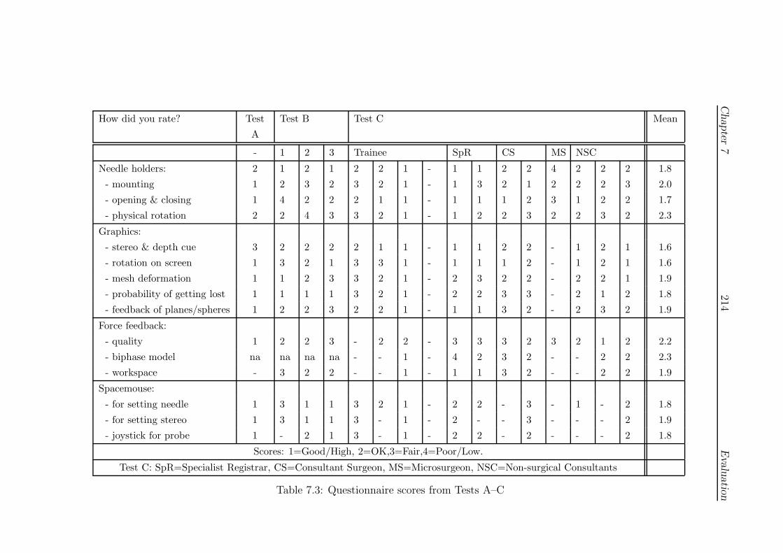
Chapter
7214
Evalu
atio
n
How did you rate? Test
A
Test B Test C Mean
- 1 2 3 Trainee SpR CS MS NSC
Needle holders: 2 1 2 1 2 2 1 - 1 1 2 2 4 2 2 2 1.8
- mounting 1 2 3 2 3 2 1 - 1 3 2 1 2 2 2 3 2.0
- opening & closing 1 4 2 2 2 1 1 - 1 1 1 2 3 1 2 2 1.7
- physical rotation 2 2 4 3 3 2 1 - 1 2 2 3 2 2 3 2 2.3
Graphics:
- stereo & depth cue 3 2 2 2 2 1 1 - 1 1 2 2 - 1 2 1 1.6
- rotation on screen 1 3 2 1 3 3 1 - 1 1 1 2 - 1 2 1 1.6
- mesh deformation 1 1 2 3 3 2 1 - 2 3 2 2 - 2 2 1 1.9
- probability of getting lost 1 1 1 1 3 2 1 - 2 2 3 3 - 2 1 2 1.8
- feedback of planes/spheres 1 2 2 3 2 2 1 - 1 1 3 2 - 2 3 2 1.9
Force feedback:
- quality 1 2 2 3 - 2 2 - 3 3 3 2 3 2 1 2 2.2
- biphase model na na na na - - 1 - 4 2 3 2 - - 2 2 2.3
- workspace - 3 2 2 - - 1 - 1 1 3 2 - - 2 2 1.9
Spacemouse:
- for setting needle 1 3 1 1 3 2 1 - 2 2 - 3 - 1 - 2 1.8
- for setting stereo 1 3 1 1 3 - 1 - 2 - - 3 - - - 2 1.9
- joystick for probe 1 - 2 1 3 - 1 - 2 2 - 2 - - - 2 1.8
Scores: 1=Good/High, 2=OK,3=Fair,4=Poor/Low.
Test C: SpR=Specialist Registrar, CS=Consultant Surgeon, MS=Microsurgeon, NSC=Non-surgical Consultants
Table 7.3: Questionnaire scores from Tests A–C

Chapter 7 215 Evaluation
• The system should help with practice by the NDH.
• The feedback given by the planes was helpful.
• The visual feedback was impressive and helped to create an ‘enjoyable chal-
lenge’.
See Section 7.5 for further discussion of these points.
7.4.4.2 VR simulator assessment
Given the exploratory nature of the test, participants were permitted to chose which
technique to attempt. In practice, most subjects adopted techniques they were com-
fortable with, the most basic forehand/forehand technique being the most common,
whilst the more senior surgical staff tended to try more complex skills with targeting
such as forehand/overhand grabbing. This variation in practice may have acted to
reduce significant differences, but does give some insight into the range of techniques
which the simulator might be required to represent.
The metrics discussed here are identical to those for Test A (7.2). For all the
plots, the DH groups are denoted as: SHO (Senior House Officer), SpR (special-
ist registrar), CS (consultant surgeon), MS (microsurgeon) and NSC (non-surgical
consultants). For the NDH, two groups are represented for the unimanual (1h) and
bimanual (2h) conditions. Results from some of the Test A trials (the 1st, 14th and
43rd) are also presented here for comparison and are discussed further in Section
8.3.1.
1. Plane angular error
• Figure 7.15 displays a boxplot of the difference between average planes
of entry and exit. Although the more highly trained groups appear to
have smaller variances, this may be due to the smaller numbers involved
in the non-trainee groups and is not significant. The average error across
all groups was 11.5◦ and the median was 9.2◦, suggesting that a figure
of around 10◦ may be acceptable, at least for this apparatus. However,
it also notable that several individuals achieved an average of c.5◦.
• An unexpected result of this test is that the NDH conditions show signif-
icantly lower errors than the remaining groups at the p < 0.05 level (in
Welch t-tests).

Chapter 7 216 Evaluation
010
2030
4050
group
Angu
lar d
iffer
ence
bet
ween
pla
nes
(deg
rees
)
A1 A14 A43 SpR(1h)
SpR(2h) SHO SpR CS MS NSC
NDHDH
Test
A
Test
C
Figure 7.15: Difference between entry and exit planes
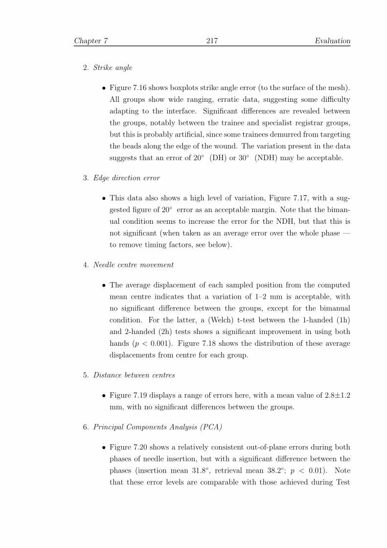
Chapter 7 217 Evaluation
2. Strike angle
• Figure 7.16 shows boxplots strike angle error (to the surface of the mesh).
All groups show wide ranging, erratic data, suggesting some difficulty
adapting to the interface. Significant differences are revealed between
the groups, notably between the trainee and specialist registrar groups,
but this is probably artificial, since some trainees demurred from targeting
the beads along the edge of the wound. The variation present in the data
suggests that an error of 20◦ (DH) or 30◦ (NDH) may be acceptable.
3. Edge direction error
• This data also shows a high level of variation, Figure 7.17, with a sug-
gested figure of 20◦ error as an acceptable margin. Note that the biman-
ual condition seems to increase the error for the NDH, but that this is
not significant (when taken as an average error over the whole phase —
to remove timing factors, see below).
4. Needle centre movement
• The average displacement of each sampled position from the computed
mean centre indicates that a variation of 1–2 mm is acceptable, with
no significant difference between the groups, except for the bimanual
condition. For the latter, a (Welch) t-test between the 1-handed (1h)
and 2-handed (2h) tests shows a significant improvement in using both
hands (p < 0.001). Figure 7.18 shows the distribution of these average
displacements from centre for each group.
5. Distance between centres
• Figure 7.19 displays a range of errors here, with a mean value of 2.8±1.2
mm, with no significant differences between the groups.
6. Principal Components Analysis (PCA)
• Figure 7.20 shows a relatively consistent out-of-plane errors during both
phases of needle insertion, but with a significant difference between the
phases (insertion mean 31.8◦, retrieval mean 38.2◦; p < 0.01). Note
that these error levels are comparable with those achieved during Test
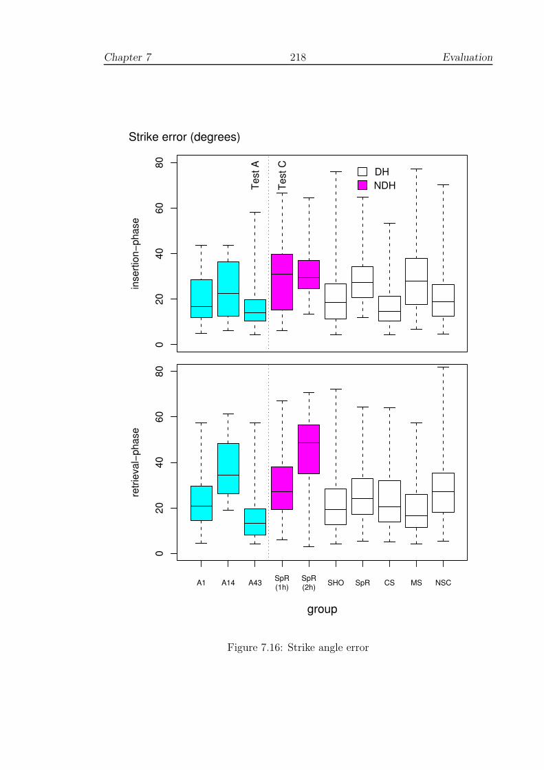
Chapter 7 218 Evaluation
020
4060
80
inse
rtion
−pha
seStrike error (degrees)
NDHDH
Test
A
Test
C
A1 A14 A43 SpR(1h)
SpR(2h) SHO SpR CS MS NSC
group
020
4060
80
retri
eval
−pha
se
Figure 7.16: Strike angle error
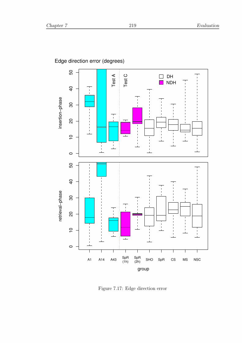
Chapter 7 219 Evaluation
010
2030
4050
inse
rtion
−pha
seEdge direction error (degrees)
NDHDH
Test
A
Test
C
group
A1 A14 A43 SpR(1h)
SpR(2h) SHO SpR CS MS NSC
010
2030
4050
retri
eval
−pha
se
Figure 7.17: Edge direction error
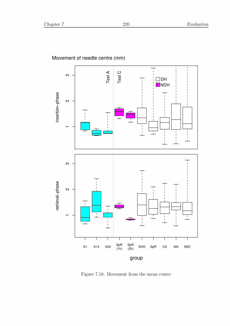
Chapter 7 220 Evaluation
12
3
inse
rtion
−pha
seMovement of needle centre (mm)
NDHDHTe
st A
Test
C
A1 A14 A43 SpR(1h)
SpR(2h) SHO SpR CS MS NSC
group
12
3
retri
eval
−pha
se
Figure 7.18: Movement from the mean centre

Chapter 7 221 Evaluation
12
34
5
group
Dist
ance
bet
ween
nee
dle
cent
res
(mm
)
A1 A14 A43 SpR(1h)
SpR(2h) SHO SpR CS MS NSC
NDHDH
Test
A
Test
C
Figure 7.19: Distance between entry and exit centres
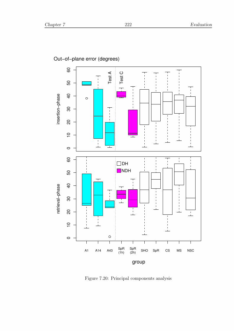
Chapter 7 222 Evaluation
010
2030
4050
60
inse
rtion
−pha
seOut−of−plane error (degrees)
Test
A
Test
C
A1 A14 A43 SpR(1h)
SpR(2h) SHO SpR CS MS NSC
group
010
2030
4050
60
retri
eval
−pha
se
NDHDH
Figure 7.20: Principal components analysis

Chapter 7 223 Evaluation
A. There is a small but non-significant improvement between the NDH
conditions, when using both hands.
7. Movement efficiency
• Figures 7.21 and 7.22 show the total displacement of the PHANToM
endpoint and time taken for passing the needle through the vessel. Several
points are noteworthy:
• There are significant differences between consultant surgeons (CS and
MS) and SHOs during the insertion phase (time p < 0.01; displacement
p < 0.001) indicating that construct validity holds for this metric espe-
cially during this phase. However, there were no significant differences
between these groups for overall or inter-stitch time (including the groups
with the NDH condition).
• The use of both hands has a striking and opposing effect during insertion
and retrieval, the former taking longer and requiring a greater displace-
ment to set up the alignment of the needle, but with a corresponding
speeding up effect during retrieval: the two-handed conditions are neg-
atively correlated with r2 = −0.997, p < 0.05 for displacement (this
correlation is not significant for time taken, but note that there is only 1
dof).
8. Maximum applied forces
• Given the earlier disparity observed with regard to forces exerted (Sec-
tion 2.4.3.4), Figure 7.23 displays a boxplot of the maximum magnitude
of force response registered by the system. It is difficult to interpret these
data clearly, since the use of a velocity threshold for determining puncture
felt unrealistic to some of the clinicians tested and would have tended to
increase force responses. Interestingly, the Test A data and the biman-
ual condition show non-significant decreases in force response, perhaps
reflecting some degree of accustomisation to the choice of threshold.

Chapter 7 224 Evaluation
010
2030
4050
inse
rtion
−pha
seTotal displacement (mm)
NDHDH
Test
A
Test
C
A1 A14 A43 SpR(1h)
SpR(2h) SHO SpR CS MS NSC
group
010
2030
4050
retri
eval
−pha
se
Figure 7.21: Movement of the PHANToM endpoint
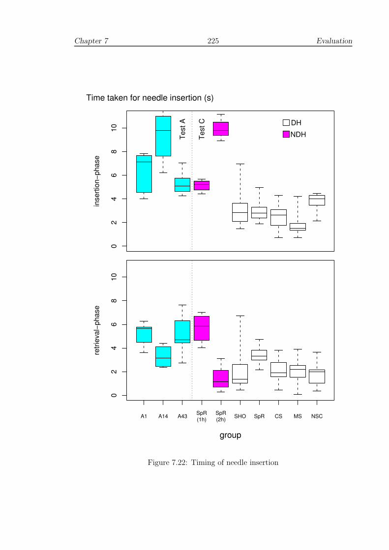
Chapter 7 225 Evaluation
02
46
810
inse
rtion
−pha
seTime taken for needle insertion (s)
NDHDH
Test
A
Test
C
A1 A14 A43 SpR(1h)
SpR(2h) SHO SpR CS MS NSC
group
02
46
810
retri
eval
−pha
se
Figure 7.22: Timing of needle insertion

Chapter 7 226 Evaluation
0.0
0.1
0.2
0.3
0.4
0.5
0.6
inse
rtion
−pha
seMaximum force response (N)
NDHDH
Test
A
Test
C
A1 A14 A43 SpR(1h)
SpR(2h) SHO SpR CS MS NSC
group
0.0
0.1
0.2
0.3
0.4
0.5
0.6
retri
eval
−pha
se
Figure 7.23: Maximum force response
Chapter 7 227 Evaluation
7.5 Summary of test results
7.5.1 Test A: Learning curve
Hypothesis test results:
The results presented above allow qualification of the sub-hypothesis introduced in
Section 7.1.2, as follows:
HA: Performance showed a complex learning curve with significant improve-
ment in terms of error reduction, and, at least for this training model,
many of the errors identified were brought to within a comparable region
to expert performances measured during Test C. Performance was also
retained during retention tests, nearly 6 weeks later, hence demonstrat-
ing consistency and persistency.
Discussion:
Since only one individual took part in this test, it is difficult to generalise to a wider
population but the results do indicate improvement over time with six hours’ training
in as many sessions. The improvement in performance was linked to reduced error
scores, increasing consistency and was retained for a period of at least 40 days. This
was not a straightforward improvement, however, but appeared to comprise three
phases:
1. An initial phase of little or no real change, which continues for several sessions;
2. A second much more chaotic phase, with a diverse range of error scores from
one trial to the next;
3. A final phase in which there is a good degree of consistency between adjacent
scores, and performance seems to have arrived at plateau. The final level
of performance was often close to that of the clinicians in Test C (Figures
7.15–7.22) and indicates some degree of equivalence at least for this test.
The form of these phases suggests that existing pre-conceptions and ‘programming’
might need to be ‘broken’ before new learning can take place. This view is consis-
tent with the various learning stage models developed by motor psychologists (see
3.5.4). Breaking ‘old habits’ sometimes requires many practice trials, during which
performance may be highly unstable [267, p. 216]. Alternatively, it may be that

Chapter 7 228 Evaluation
various strategies were being tested in a cyclic fashion, in the manner suggested
by Nourrit et al for skiing simulation (Section 3.5.9.2). Whatever the root causes
of these phenomena, it is clear that these phases of learning are poorly described
by linear or random effects models and that unless specific care is taken, statistical
analyses may be inappropriate. In particular, it would seem to be necessary to run
tests over a sufficient length of time, preferably with a well-matched control group.
Before a deeper understanding of the effects of simulator training can be achieved,
however, it would seem that research to validate learning models must be made a
greater priority (see 8.2.3).
7.5.2 Test B: Using real tools
Hypothesis test results:
HB: Performance on the simulator did not produce significant improvement
using real-world tools; although some improvement in suturing was in-
dicated, this was not sufficient to outweigh the practice effect of testing
(at least to the point of significance).
Discussion:
Although non-significant, the test provided data to assist with possible future in-
vestigations by allowing a prediction of power based on the variances obtained. In
looking at the results from Test A, it is also likely that power would have been
greatly improved by doubling or tripling the number of sessions. A major difficulty
with this type of test, however, is the problem of assessing the quality of sutures
below the surface of the pad and it is not clear how this might be remedied in future,
unless testing is performed with tracking devices (see 2.2.3).
7.5.3 Test C: Usability study
Hypothesis test results:
HC : The performances of clinicians did not violate the property of construct
validity, which was, in fact, demonstrated to hold for some efficiency
metrics — time taken and distance moved (during insertion).

Chapter 7 229 Evaluation
Discussion:
Despite some important criticisms, mainly in relation to force rendering and the
weight of the instrumented PHANToM, the system was well-received by the majority
of clinical staff and all respondents accepted the potential benefit to training. Use of
the NDH tended to increase errors and time taken, which suggested that some loss
of performance was acceptable in situations where the DH was unable to reach. The
bimanual condition had a significant effect upon performance, increasing the time
taken, but sometimes significantly reducing errors (even compared to DH groups).
A striking feature of the consultants’ performance was that it was generally much
faster than the remaining groups over the critical period of needle insertion. Overall
time taken was not significantly different, suggesting that more time was spent in
preparation. This point is discussed further in Section 8.3.1, but since errors are
not significantly different, the implication would seem to be that there is a strong
element of technique involved.
7.6 Developing a scoring system
7.6.1 Scoring and feedback?
Data on time and displacement parameters were deliberately withheld during the
evaluation tests to emphasise specific feedback on errors (using the graphical dis-
play). This was sufficient to promote learning in Test A, but a number of clinicians
commented that some form of scoring system was also required.
During Test C, it was also observed that the fastest trainees tried to adopt a
fixed arm/wrist position which suggested some indifference to the task. In fact,
their behaviour suggested a reduction of the task by first establishing a comfortable
working position in front of the PHANToM and then probing the mesh until the
correct angle of approach was found, Figure 7.24. This (eventually) allowed fast
movements with low error scores, but since targeting skills were not being acquired,
these successful results would not have been likely to transfer to other suturing tasks.
In hindsight, therefore, the decision not to reveal timing information would seem to
have been correct, but the absence of a target-related score was a serious omission.
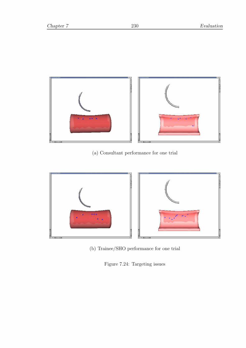
Chapter 7 230 Evaluation
(a) Consultant performance for one trial
(b) Trainee/SHO performance for one trial
Figure 7.24: Targeting issues
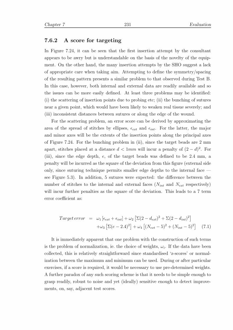
Chapter 7 231 Evaluation
7.6.2 A score for targeting
In Figure 7.24, it can be seen that the first insertion attempt by the consultant
appears to be awry but is understandable on the basis of the novelty of the equip-
ment. On the other hand, the many insertion attempts by the SHO suggest a lack
of appropriate care when taking aim. Attempting to define the symmetry/spacing
of the resulting pattern presents a similar problem to that observed during Test B.
In this case, however, both internal and external data are readily available and so
the issues can be more easily defined. At least three problems may be identified:
(i) the scattering of insertion points due to probing etc; (ii) the bunching of sutures
near a given point, which would have been likely to weaken real tissue severely; and
(iii) inconsistent distances between sutures or along the edge of the wound.
For the scattering problem, an error score can be derived by approximating the
area of the spread of stitches by ellipses, εext and εint. For the latter, the major
and minor axes will be the extents of the insertion points along the principal axes
of Figure 7.24. For the bunching problem in (ii), since the target beads are 2 mm
apart, stitches placed at a distance d < 1mm will incur a penalty of (2 − d)2. For
(iii), since the edge depth, e, of the target beads was defined to be 2.4 mm, a
penalty will be incurred as the square of the deviation from this figure (external side
only, since suturing technique permits smaller edge depths to the internal face —
see Figure 5.3). In addition, 5 sutures were expected: the difference between the
number of stitches to the internal and external faces (Nint and Next respectively)
will incur further penalties as the square of the deviation. This leads to a 7 term
error coefficient as:
Target error = ω1 [εext + εint] + ω2
[
Σ(2 − dext)2 + Σ(2 − dint)
2]
+ω3
[
Σ(e − 2.4)2]
+ ω4
[
(Next − 5)2 + (Nint − 5)2]
(7.1)
It is immediately apparent that one problem with the construction of such terms
is the problem of normalization, ie. the choice of weights, ωi. If the data have been
collected, this is relatively straightforward since standardised ‘z-scores’ or normal-
ization between the maximum and minimum can be used. During or after particular
exercises, if a score is required, it would be necessary to use pre-determined weights.
A further paradox of any such scoring scheme is that it needs to be simple enough to
grasp readily, robust to noise and yet (ideally) sensitive enough to detect improve-
ments, on, say, adjacent test scores.

Chapter 7 232 Evaluation
7.6.3 Preliminary results
As an early discrimination test of the targeting coefficients outlined, Figure 7.25
displays a pairs plot with groups separated by colour. It should be noted that given
variations in the techniques adopted and the short period of testing, the level of
discrimination would not be expected to be perfect. Several features are, however,
of interest:
• all the error coefficients isolate those individuals who did not aim carefully;
• the registrar who used the NDH to perform the tasks is weakly isolated in the
unimanual condition, but is strongly separated in 3 out of 4 error terms in the
bimanual condition (the exception being with respect to ‘bunching’);
• the consultant groups are generally well-represented in the region of the lowest
errors, whilst the trainees display a spread of errors across a broad range. The
trainees who did not target the needle as intended are well discriminated, as
intended.
Given the limitations of the data, it would be unwise to comment further, but it
is possible to see that the plot gives a straightforward method of selection of the
weights, ωi.
7.6.4 Towards an overall score
Further discussion on combining individual error scores is given in Section 8.2.3, but
time precludes developing or testing an overall scoring procedure here. It is sug-
gested, however, that this might be achieved along similar lines, combining angular
and target-related scores into a unique index. It may also be that timing information
should also be made available, but perhaps only at the end of any given session, so
that testees are not tempted to ‘race against the clock’.

Chapter 7 233 Evaluation
ellipse100
150 100 150
0
500 50
bunch681012
6 8 10
0246
0 2 4 6
edge_depth
2025 15 20 25
05
10
0 5 10
hit_error6080100
60 80
02040
0 20 40
SpR/1hSpR/2h
SHOSpR
CSMS
NSC
Figure 7.25: Target error discrimination plot
where:
SHO=Senior House Officer, SpR=Specialist Registrar, CS=Consultant Surgeon(vascular), MS=Microsurgeon and NSC=Non-Surgical Consultants. For the NDH,two groups are represented for the unimanual (SpR/1h) and bimanual (SpR/2h)
conditions.

Chapter 8
Discussion
This chapter gives a review of the present findings with respect to surgical
simulation, beginning with a synthesis of previous chapters (Section 8.1). The
synthesis builds a critique of construct validity testing in the simulation lit-
erature. Data from individual performances are then re-examined to attempt
to develop an understanding of error control in relation to surgical technique
ie. towards a model for motor learning (Section 8.2). The chapter closes by ad-
dressing the limits of the present investigations and making recommendations
for future work (Section 8.3).
‘Above all else show the data.’
- Edward R. Tufte, The Visual Display of Quantitative Infor-
mation, 2001
8.1 Synthesis
8.1.1 Motivation
Despite proposals to shorten surgical apprenticeships, which are to be fully intro-
duced by 2005, the medical profession has yet to find adequate methods of acceler-
ating the training of junior doctors. In other industries where highly technical skills
must be acquired, this problem has been addressed by the development of simulators
234
Chapter 8 235 Discussion
to give standard training drills. In surgery, however, convincing simulations have
yet to be fully realised, let alone certified, and this problem is compounded by the
many forms of specialisation which surgery can take (vascular, cardiac, radiology
etc.). As a consequence, instead of standard interfaces in which, say, pilots may
transfer skills from one aircraft to the next, a range of simulations are needed with
any number of models to represent potential complications and disease.
8.1.2 Assessing simulators
The development of MIS and interventional techniques in the 1990s led to a public
outcry about skills training in the medical profession. The resulting debate provided
a good opportunity for VR researchers to create and test surgical simulators as
the interfaces were relatively straightforward to reproduce. But although several
commercial simulators have now been developed, the cost of VR systems to teaching
schools still remains an issue and few have enjoyed medical endorsement. Hence
there is an urgent need to establish the potential benefits of simulators. A further
problem, which seems to complete a vicious circle, is that the evaluation of these
systems requires the input of health professionals, who are neither able to commit
long periods of time to assessments, nor willing to put patients at an unnecessary
risk.
This situation has resulted in the development of various ‘home-grown’ meth-
ods of surgical simulator assessment (surveyed of Chapter 2). Some researchers, for
example, have favoured dexterity tests (eg. using ADEPT, ICSAD) and have been
able to show concurrency between tests and independent clinical assessments. How-
ever, factors such as age, sex and handedness weaken the reliability of these tests
and other research has shown that even modest amounts of training tends to blur
distinctions between measured ability levels.
Instead of longer term transfer or retention tests (8.1.3), many researchers have
preferred the quasi-experimental approach of establishing construct validity. This
might be expected, given, as noted above, that surgeons usually have heavy commit-
ments. All too often, however, it appears that researchers have applied the construct
validity test without further analyses, as if good discrimination between experts and
novices is a useful endpoint in itself. A little reflection shows that this is not so:
experts are expected to be more capable than novices and a favourable result only
proves that the system under test has not distorted this fact.
A more appropriate experimental design might, say, randomize experts and

Chapter 8 236 Discussion
novices into an unknown order of testing (with appropriate blinding to the test
organisers) to see if the simulator can then discriminate the expertise of participants
into realistic classes. If retention tests or blinded experiments seem too costly to im-
plement, researchers should, at the very least, ask whether construct validity holds
for a definite period of time. The BDI study of O’Toole et al [308], for example,
preserved significant differences between the expert and novice groups during the
hour-long test of each subject. The estimate given here (Section 3.5.5), however,
suggests that significant differences might have evaporated after a few more hours’
practice. Should novices be considered experts after this time? If not, the question
arises as to whether this test has achieved anything at all.
These modes of assessment contrast sharply with the recommendations of avia-
tion researchers, where results may be considered meaningless unless issues of relia-
bility have been considered. In surgical simulations, the effects of repeated testing
are usually ignored and corrections for sphericity and multiple significance tests are
generally overlooked. Worse still, misconceptions about the nature of null hypothesis
statistical tests (NHST) are rife. Few researchers have shown any appreciation of the
concept of statistical power and have often equated non-significance with support for
the null hypothesis. Equally, they have obtained data from hundreds of participants
in what critics of NHST would see as a bid to exaggerate otherwise meaningless
differences (see 8.2.1). A brief summary of assessments of the MIST-VR system
(to date, the most thoroughly tested) will hopefully be sufficient to give a synopsis
about progress in this field:
• The study by Paisley et al demonstrated that bench models were superior to
MIST in discrimination tests between experts and novices, but the retest phase
showed more gains by students and trainees on MIST than on any other device
[310]. This would seem to suggest that the MIST system possesses stronger
properties for training than for assessment (2.4.4.3).
• The later study by Gallagher et al used a very large sample population and
was able to demonstrate construct validity, although not all experts performed
well [170].
• Torkington et al showed that Basic Skills instruction was found to be as effec-
tive as MIST in a transfer test to a box trainer [420].
• Students who trained for three hours on MIST did not perform noticeably
better in the appendectomy of a pig [34].
Chapter 8 237 Discussion
• Using a regular training regimen of one hour per day for 8 days (to a preset
level of criterion performance) led to significantly improved performance with
respect to a relatively simple surgical procedure on human patients (laparo-
scopic cholecystectomy) [375].
• Chaudhry et al have shown that the initial familiarisation curve using MIST
requires up to 4 repetitions and that construct validity still holds between basic
surgical trainees and non-surgical subjects at 10 repetitions for most tasks [95].
The final level of performance at this point appeared to be asymptotic, but as
far as the author is aware, no data beyond this region are available to confirm
this.
• Grantcharov et al analysed the ‘familiarisation curves’ of three groups (experts,
novices and intermediates) in ten trials over a period of one month [187].
Significant differences between the groups were observed on the first trial, but
were not present in the last. As expected, experts showed little evidence of
learning, whilst the performance of intermediates levelled at the fifth trial and
the novices reached plateau at the seventh.
8.1.3 Training Research
In Chapter 3, the results of training research in clinical, military and industrial set-
tings were examined. In these domains, construct validity test designs appeared to
be unknown, the nearest logical equivalent being usability analyses, in which the
opinions of a range of users are assessed1. Instead, researchers are generally much
more interested in establishing transfer and retention properties of training pro-
grammes. The construction of learning curves for a number of surgical procedures
suggests that after learning the basic techniques, a distributed training schedule of
some 30–50 trials (or real cases) is effective for overcoming most errors. In addition,
surgical volume would appear to be a factor in predicting surgical outcomes indicat-
ing that, after qualification, a deliberate practice schedule should be maintained.
To quantify training, flight simulation researchers have expended a good deal
of effort in the hope of obtaining estimates for ‘transfer’. But the current consen-
sus is that accurate estimates for transfer are difficult and, more importantly, very
expensive to obtain. Indeed, many ‘transfer-of-training’ measures exist but most
should be considered meaningless unless the reliability of the test results has also
1This contrast highlights a disturbing a trend in the surgical simulation literature which is thatthe opinions of participants, however skilled, are rarely published.
Chapter 8 238 Discussion
been established. On the other hand, there is some agreement in the literature
that ‘quasi-transfer’ studies are effective. The main benefit of this approach is its
simplicity (cf. Section 3.4.3.3):-
• Treatment and control groups are trained either exclusively with or without a
particular feature of the simulator to a preset criterion level;
• In the same simulator, with the feature under test either enabled or disabled,
the groups are then re-tested, perhaps under a variety of conditions.
Section 3.5 introduced a number of principles from psychomotor research studies
which have become established over the past few decades. Failure to appreciate
this work seems to have wrong-footed a number of evaluations, such as that of
Prystowsky et al [321] (Section 2.3.5). In that study, the authors conjectured that
Schema theory, developed by Schmidt in 1975 [361], was a sufficiently sound basis for
supposing that 12 minutes’ training on the VR device would produce a significant
increase in performance on a catheter insertion simulation. In Schmidt’s theory,
however, schema are motor programmes which are developed over many deliber-
ately varied practice sessions to allow planning for related movements. Practising
throwing tasks at distances of 5m and 10m, for example, should generate good re-
sults when test throws are requested at, say, 8m. Research which has accumulated
since that time has indicated that other factors may also be present, but has not
contradicted the basic premise that practice variability is fundamentally important
in the development of motor programmes [267, 362].
A related principle, which also seems to have been frequently overlooked, is that
of practice scheduling ie. blocked versus distributed training. Whilst some evidence
exists that blocked (repetitious) training may be valuable for young or inexperienced
subjects, it should be avoided as a general rule. In particular, it seems that training
by repeating set exercises tends to give good results during practice, but when
transferred to the target environment performance is often very poor. Instead,
training schedules should deliberately mix dissimilar tasks over many sessions so
that subjects are forced to forget previous strategies in order that they have to be
reconstructed later. An important corollary is that instantaneous results (over one
session) are by definition, unreliable. Repeated tests must be performed, preferably
over several days, to gauge performance: consistency and persistency are seen as the
main markers of progress in the acquisition of skills.
A third principle, which simulator designers have tended to treat as arbitrary, is
that of feedback schedules. Intrinsic feedback, ie. that which is purely a function

Chapter 8 239 Discussion
of the task such as visual and force-feedback, must be presented appropriately in
real-time (cf. results with SKAT, Section 2.3.4). On the other hand, extrinsic feed-
back (eg. error scores) has been shown to generate very different responses — too
much score-related feedback tends to lead to charges of over-critical systems. On
balance, the evidence suggests that trainees prefer feedback after successful trials
so that they can adjust or build their own error-correction capabilities. Similarly,
augmented feedback (additional ‘virtual’ feedback, such as the BDI 3D guide vector,
see 2.4.3.3) may also be counter-productive. The evidence indicates that it tends
towards ‘crutch-like’ dependencies, with high levels of performance in practice but
poor performance in testing (ie. when the ‘crutch’ is removed) even compared to
conventionally trained subjects.
8.1.4 Modelling, design and feedback
Vascular suturing presents several major challenges both to the surgeon and to sim-
ulation (surface wounds, by their nature, would allow considerably more latitude).
The sutures must be placed to a precision of a few millimetres and the resulting
wound closed to a very smooth contour, so that patency results — without causing
further obstruction to the lumen of the vessel. The manipulation of the needle,
tissues, patches, thread etc. requires two hands working asymmetrically, the only
proviso being that occasionally the surgeon has to swap hands where access would
otherwise be far too awkward. An immediate simplification made here, using a part-
task approach, is that only one object was modelled — although we have assumed
a second object (patch, tissue etc.) may exist or may be added later.
In allowing both hands to manipulate the mesh/tissue, it was preferred that de-
formation solutions should be combined rather than assembled and solved in one
step. The main reason for this was that manipulation of the ‘tissue’ by the sup-
porting hand would indicate that the collision detection model needs to be updated.
If deformation solutions are separated, then those due to the needle can then be
superimposed on that previously obtained to update the collision detection model
and, crucially, forces can be kept consistent. FEM was seen as the model of choice
here due to its greater accuracy (than mass-spring models), suggesting better fidelity
and stability with multiple, superimposed boundary conditions.
The separation of deformation solutions also indicated that the system may ben-
efit from parallelisation. Borrowing from Guiard’s principle of asymmetric working,
a design was put forward which proposed that work with the dominant hand should

Chapter 8 240 Discussion
generate updates at c.1000 Hz for haptic rendering whilst work with the supporting
hand would only require updates at c.30 Hz for graphics and collision detection. It
was also supposed that whilst force-feedback could be related to the dominant hand
via a haptic device, a simpler joystick type interface may be acceptable for use with
the other hand, allowing more immediate control of needle angles, stereo settings
etc. than, say, requiring the user to turn to the keyboard or mouse.
Following principles derived from psychology and aviation research (8.1.3 and
Chapter 3), errors were indicated by graphical feedback when requested by the user
on clicking the mouse pointer. The errors relayed were selected on the basis of those
most likely to induce stress in the tissue: a real-time or delayed representation of
stress would have been possible (based on FEM), but was not thought likely to
have been helpful. This form of delayed graphical feedback was intended to promote
learning rather than focus purely upon skills assessment.
Chapter 6 gave a full description of elastic solid mechanics using FEM. The
method of super-condensation was then developed to allow the pre-computation
of multi-point contact models necessary for bimanual working and real-time force
display. The choice of parameters to define the tissue model were discussed and a
volume test introduced to qualify this model. An extension to approximate more
realistic tissue behaviour, the bi-phase model, was also described.
8.1.5 Evaluation
A series of pilot studies were undertaken to evaluate the FESTIVALS system which
comprised: a learning curve and retention test, a transfer test to real tool use and
a usability study. Of these, the transfer test proved to be the least successful, in
the sense that no significant results were generated. It was nevertheless possible
to use the results to give an estimate of the power of the test which may be of
interest if future trials of this kind are undertaken. The other tests suggested that
the simulator possessed several strengths and weaknesses:
• Bimanual working was permitted albeit many test respondents found the in-
terface heavy to manipulate, and against this, the haptic display felt weak,
though some people reported that this feeling improved during the session.
Although realistic tissue parameters were used, the setting of a modest re-
sponse was a deliberate policy to avoid excessive, unnerving responses and to
prevent overheating the haptic motors. For the Desktop PHANToM model
used here, overheating requires that the motors be allowed to cool for an hour
Chapter 8 241 Discussion
or so.
• Significant improvement in error scores was observed after six sessions and
was retained for many weeks. The method of delayed feedback was easy to
comprehend and was not found to be intrusive, where scoring systems might
have been demotivational or encouraged speed over technique. Many clinicians
nevertheless felt that a method of scoring was needed, both for assessment and
to encourage appropriate usage of the system.
• The system did not violate the concept of construct validity, and discrimination
was positive for some efficiency characteristics during insertion of the needle.
8.2 Towards a model for learning
8.2.1 Limitations of the construct validity test
Tests between experts and novices have become commonplace in surgical simulation
research although significant differences are usually only apparent when the test is
based on efficiency parameters, such as time taken or distance moved [47, 48, 125,
126]. It is implicitly assumed that technical errors will cause delays or unnecessary
movement and that measures of inefficiency will be inflated as a consequence. If
this is not the case, perhaps because some illegal strategy is being employed, then
the test may unaccountably fail. In vascular procedures, for example, the patient
must always be kept in line of sight and hence minimal movement of the hand often
requires a curved path. It follows that violations of this rule, if not detected by the
simulator, may bias efficiency scores unfairly.
A further problem is that an optimal level of performance is always assumed
to be paramount: the evidence here (although limited) suggests that a lower level
of performance with the non-dominant hand may be preferable in situations where
manoeuvring around obstructions with the dominant hand may be too slow or ham-
pered. In such circumstances, it would be of considerably greater value to see how
trainees cope with unusual circumstances, ie. how skills are transferred, rather than
their best time in practice. Performance may also be depressed during training, an
effect which was seen here and has been reported by numerous other researchers
eg. Rosen et al [344] (2.3.4).
The fidelity of simulations is another issue which distinguishes assessment-oriented
approaches from training approaches. In the assessment approach, significant dis-
Chapter 8 242 Discussion
crimination of experts from novices is taken to be prima facie evidence of the value
of the bench model or VR test. From the various studies of this kind, however, it
has been consistently shown that individual differences tend to converge rapidly with
practice (3.5.3) and even short periods of rehearsal can remove significant differences
[48]. In these cases, therefore, it is difficult to know if the fidelity of the model has
contributed to the success or failure of the test, especially if users’ opinions are not
reported. In fact, it seems necessary always to ask how much practice or experience
would remove significant differences or, more simply, ‘how reliable is the test?’.
This basis of construct validity testing was explored and challenged in Sections
3.3.2 and 3.6.2, where it was argued that this loss of reliability should be a major
cause for concern. Significant differences are frequently observed between experts
and novices, giving some level of support for the central construct that simulators
can measure surgical skill. But, as noted above (and see 8.3.3), the usefulness of
such tests for assessing trainees of intermediate status is in doubt. Given the premise
that a consistent framework of theory is needed around such constructs [88, 304],
this lack of resolution indicates that a period of reflection and reconstruction is now
long overdue. A clearer model of learning is now vital. In their ski simulation study,
Nourrit et al suggested that trainees learn by alternating between rival strategies
(Section 3.5.9.2) and this interpretation would certainly be supported by the data
generated here. In such circumstances, longer periods of training and retention
testing are crucial if reliability is to be established.
In training-oriented studies, skills training, even with low fidelity simulators,
has been shown to produce significant improvements over conventional classroom
instruction [189, 353] and other researchers have found that departures from the
highest levels of fidelity can actually enhance transfer [332, 414]. For simulator
developers, this is usually a much more meaningful result. We are tempted to ask:
‘what features of these training models might be important, and what aspects of
training were missed?’. To respond to this question, the training-oriented groups
may also have an answer — using backwards quasi-transfer (3.4.3.2).
8.2.2 Null hypothesis significance testing
The application of construct validity tests without regard for other forms of anal-
yses appears to be symptomatic of null hypothesis significance testing (NHST) in
general. Without other checks, it is often difficult to interpret NHSTs and critics
of the method have often been scathing: ‘significance testing retards the growth

Chapter 8 243 Discussion
of scientific knowledge; it never makes a positive contribution’ (Schmidt & Hunter
1997, quoted in Nickerson [297]). The psychology literature in particular shows a
greater awareness of controversy about NHST. One of the main areas of confusion
is in the conditional nature of the probabilities involved, such as the nature of Type
I and II errors (some definitions are given in Appendix A.5). Another grey area is
the difference between statistical and practical significance2.
With this warning in mind, how should construct validity tests be interpreted? If
the performance of experts and novices has been shown to be significantly different,
this is of interest to the developers since it indicates (but does not prove) that the
VR task gives an approximation to the real procedure. Importantly however, this
result may be of little interest to clinicians since, as Reznick commented on the BDI
simulator (2.4.3.3):
The two groups are very disparate in terms of their surgical capabilities.
It may be that simple explanations, like the ability to handle the needle
holder or understanding the concept of pronation or supination in placing
a needle, are as operative as the more complex abilities of performing
the complete task of suturing [336].
In short, too much reliance has been placed upon the success or failure of construct
validity tests and insufficient attention paid to the way that skills are acquired. One
consequence is that little progress (if any) has been made in incorporating these
systems into surgical training programmes. This situation is similar to that in avia-
tion research over a decade ago (see 3.2.2) and indicates that despite the ingenuity
of developers, the potential of VR to enhance learning in surgical techniques is still
poorly understood.
8.2.3 Aspects of technique
Defining technique and measuring specific sources of error is not trivial. In the
evaluation results of Test B, for example, the asymmetry of the pattern of sutures
was due to a mixture of instrument handling, approach angles, depth of insertion
etc. and it was not possible to quantify these adequately from the surface data
(7.5.3). Similarly, efficiency metrics combine errors from many different sources,
which are equally impossible to resolve.
2Consider a hypothetical dart-throwing experiment in which the treatment group is blindfolded:the results may be highly significant statistically, but of no practical interest.

Chapter 8 244 Discussion
Since approach angles etc. can be easily sampled at high frequencies in VR de-
vices, this section gives a post-hoc examination of the evaluation data to look at other
potential error metrics and relationships. Attention here is focused upon angular
changes during the insertion phase of each attempted suture as this was thought to
be one of the most likely to cause tissue distress, especially if large or sudden move-
ments could be detected. Figure 8.1 gives a visual display of accumulated twisting
of the needle over this cycle. This quantity is related to Plane angular error (see
7.2.4). Here, however, the angular difference between each plane normal sampled
(at c.33 Hz) is accumulated. Note that feedback during practice only gave graphical
output of the average plane, and hence no information was provided to participants
on this metric.
In the plot of Figure 8.1, only the results from a defined section of time are given,
using sutures from the last session of surgical participants of Test C. The plot is
intended to be read from top left to bottom right across the page in increasing order
of experience: SHOs (Senior House Officers), SpRs (registrars) and CS (consultant
surgeons). It can be seen the strokes formed tend to follow a similar slope which
appears to be systematic error due to vibration modes of the hand and the equipment
(namely the PHANToM). Deviation from this average slope suggests a significant
contribution from human movement.
As a check of construct validity, it may be observed that the plot indicates that
movements become more controlled and reduced in higher grades of expertise with
less frequent sharp jumps (some of which are presumably a result of difficulty in
handling the interface). The height of each stroke — ie. the total accumulated twist
— is also reduced and this factor is significantly different between the SHO and
SpR, and the SHO and CS groups at the p < 0.01 level. As a further check, it is
interesting to note that this quantity was also observed to improve across the Test A
practice trials during both the insertion (F = 2.169, p < 0.001) and retrieval phases
(F = 4.229, p < 0.001).
It was anticipated that significant jumps (‘steps’ in the plot) would be more
likely to occur at the end of each stroke ie. due to the release of the locking mecha-
nism, but this does not seem to be the case. In fact, movements across this region
are remarkably smooth and this would seem to be especially true for the registrar
working with the non-dominant hand — the chief impact of which is in the height
of the stroke. The latter seems to reflect increased efficiency of the insertion phase
by consultants (see 7.4.4.2 and Figure 7.22). It should noted, however, that there
were no significant differences between these groups for overall time per stitch or
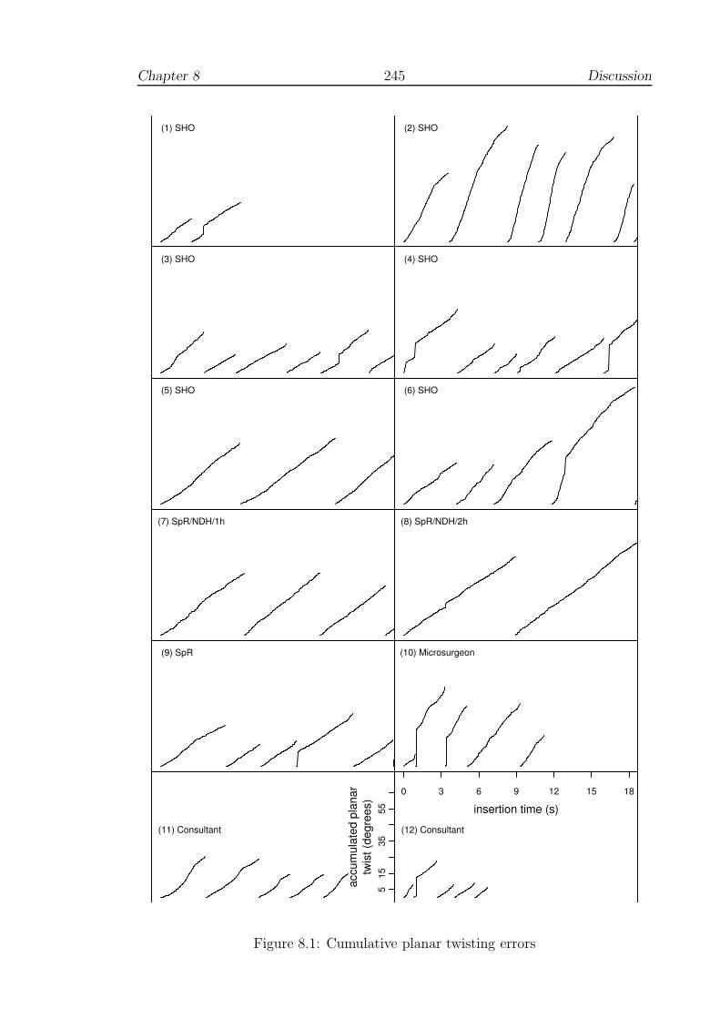
Chapter 8 245 Discussion
(1) SHO (2) SHO
(3) SHO (4) SHO
(5) SHO (6) SHO
(7) SpR/NDH/1h (8) SpR/NDH/2h
(9) SpR (10) Microsurgeon
0 3 6 9 12 15 18
insertion time (s)(11) Consultant (12) Consultant
515
3555
accu
mul
ated
pla
nar
twist
(deg
rees
)
Figure 8.1: Cumulative planar twisting errors

Chapter 8 246 Discussion
inter-stitch time (even with the NDH condition) and hence the total planar twist
quantity would seem to be much more closely related to specific technical expertise.
8.2.4 Error correction
The use of more visual data displays in the above, rather than overall test statistics,
is thought to be a valuable contribution since it gives a clearer understanding of
the nature of the data and may be able to provide more useful feedback to trainees.
Since the system defines discrete phases for the components of each suture (5.2.2.3),
it is possible to correlate different error quantities in the same display. The result-
ing profiles must be interpreted with care, however, as the parameters are usually
measured with respect different reference criteria. The striking angle was an obvi-
ous choice for investigation here because it already has an obvious reference to the
normal of the intersected triangle and the data showed a large range of variation.
Twisting of the needle during the insertion phase was suspected to be closely
linked with elevating stress levels in tissue. To investigate the relationship with
the strike error, therefore, a further error term, precession error, was defined as the
angle between the normal of the needle plane and the average normal of the phase.
This definition is intended to convey that the error describes an angle of precession
ie. that the needle was being twisted about a relatively stable axis of rotation. This
interpretation is partly based upon the appearance of the data and is discussed
further below.
Figure 8.2 plots the precession error against strike error for a small number of
adjacent test sutures obtained from surgical trainees, registrars and consultants in
Test C. (Appendix E contains additional plots of these error profiles from all the
surgical trainees, registrars and consultants in Test C, see Figures E.1 and E.2.) The
aim of these plots is to present a visual record in the manner recommended by Tufte
[426, 427], so that patterns in the data can be examined by eye. There are several key
points to make in general: firstly, the plots show a progression from less experienced
SHOs at top-left, to consultants at bottom-right; and secondly, complete trials are
shown, so that adjacent suture attempts are adjacent in the figure.
It should be emphasised that any conclusions drawn must be tentative, given the
limited size of the data set and some level of variation in the clinicians’ choice of
approach. In general, however, the consultants’ movements appear to be defined by a
smaller number of features, which occur more often in parallel. Also, the consultants
appear to be more much more likely to repeat this strategy from one ‘stitch’ to the

Chapter 8 247 Discussion
10 14 18 22
510
1520
25
10 15 20 25 30
510
2030
15 25 35 45
510
15
10 20 30 40 50
510
2030
15 20 25 30 35 40
12
34
56
7
5 10 15 20
0.5
1.0
1.5
2.0
10 20 30
1.0
2.0
3.0
10 15 20 25
0.0
1.0
2.0
25 35 45 55
0.0
1.0
2.0
3.0
10 20 30 40
24
68
10
10 20 30 40
510
1520
20 30 40 50
510
15
20 30 40 50 60
01
23
45
6
20 30 40 50
01
23
4
20 30 40 50
01
23
4
20 30 40 50
01
23
45
15 25 35 45
0.5
1.0
1.5
2.0
5 15 25 35
0.5
1.0
1.5
15 25 35 45
0.5
1.0
1.5
2.0
10 15 20 25 30
24
68
10
5 10 15 20
01
23
45
67
10 15 20 25 30
01
23
45
10 20 30
12
34
5 15 25 35
12
34
56
Prec
essio
n er
ror d
urin
g in
serti
on (d
egre
es)
Strike error during insertion (degrees)
KEY: (start points) SHO Registrar Consultant
Figure 8.2: Selected precession error profiles
(NB. Scales vary, axes are drawn through the centroid of each profile)

Chapter 8 248 Discussion
next with their movements kept within the same error region (Figure E.2). The
trainee data, on the other hand, shows much greater variation with more frequent
and larger ’jumps’, indicating large potential stresses. It is argued, therefore, that
the plots suggest a greater level of organisation in the movement actions of experts,
since there is a more deliberate rhythm in which a motor strategy has been planned
or selected before being executed.
In brief, the experts’ data appears to be less convoluted: the occurrence of
parallel, perpendicular and even, sometimes, horizontal and vertical paths would
seem to indicate that errors are being corrected in a much more deliberate pattern.
That one angle seems to be held constant, whilst the other is adjusted, is the reason
behind the use of the term precession here: the implication is that experts are using
a few stable axes of rotation and applying corrections by making adjustments along
each in turn. Novices on the other hand, are less able to control these adjustments,
and the axes of rotation seem to vary. This interpretation, albeit tentative, is in
good agreement with Adams’ definition of skill as the ability ‘to bring about some
end result with maximum certainty and minimum outlay of energy’ (3.5.1).
These plots are offered as a potential basis for future research as time does not
permit more complex statistical analysis here. It is possible, however, to look for
corroboration in these inferences using the learning curve data. In Figures E.3 and
E.4, there is a marked tendency towards large horizontal jumps during the earlier
phases, which diminishes a little over time, but suggests better control of precession
error than strike error especially in the beginning. Interestingly, however, the plot
pattern seems most organised during the retention phase, with the recurrence of a
diagonal ‘cross’ shape. If this is genuine, it suggests that the weeks between practice
and retention tests were important for reorganisation of motor behaviour. It is also
fascinating to note that this pattern seems to be echoed by earlier ‘cross’ patterns
during the more chaotic central phase of training (‘phase II’), suggesting that this
new action plan for error-correction was incipient at that time.
8.3 Future work
8.3.1 Limits of performance
To gauge possible areas of improvement and to provide an estimate of the training
limits of the system, Table 8.1 gives the best median values obtained for various
error metrics in Tests A and C (median values are thought to be a better estimate

Chapter 8 249 Discussion
of the central value given the limited nature of the Test C data). A number of
features are of note:
1. The Test A data shows a general improvement (but note that this data does
not describe the more erratic central phase) such that plane, strike and edge
direction errors are poorly distinguished between the last Test A trial, the
SHO and CS groups (these differences were non-significant though perhaps
with more data, these may have become so);
2. For the time taken for each suture (total and the inter-stitch time), the table
shows large difference between the last Test A trial and the SHO and CS
groups, with the former taking c.50% longer to complete each suture; the CS
and SHO groups, however, are indistinguishable;
3. The performance of consultants is distinguished (and is generally significantly
different) from the other groups in the time taken and total displacement
during the insertion and retrieval phases, sometimes by a factor of 2 or more.
The last point might seem to indicate that the consultants’ performance has merely
become more efficient with time, following some ‘practice law’. From the first 2
points, however, it is clear that this faster performance has not resulted in greater
levels of error or faster overall performance. This suggests that the experts may be
preparing more carefully so that greater performance is obtained during the more
critical insertion and retrieval movements ie. that there is much stronger element of
technique involved. This view is supported by the evidence for greater error control
during these phases described above (8.2.4). Otherwise, some kind ‘speed-accuracy
trade-off’ — in the manner of Fitts’ Law (3.5.5.2) — would be expected.
8.3.2 The physical interface
The favourable comparison between that obtained during the last trial in Test A
and the consultants’ performance and in Table 8.1 indicates that the system may be
adequate to provide some level of training and assessment. Plane errors of c.10◦ and
edge direction or strike errors of c.15◦ seem apparently reasonable. It is likely,
however, that it is the system itself which is imposing these limits and many users
reported having some difficulty with the interface. This section briefly outlines some
possible adaptations for improvement.

Chapter
8250
Discu
ssion
Phase Test A practice trials NDH trials SHO CS
first last 1-
handed
2-
handed
Plane angle (◦) — 36.9 7.0 5.0 2.2 7.6 11.7
Edge insertion 32.0 16.5 14.2 19.7 15.6 17.8
direction (◦) retrieval 17.9 16.1 11.8 20.0 19.3 22.7
Strike angle insertion 16.8 14.1 31.0 29.4 18.4 14.6
(◦) retrieval 20.9 13.2 27.2 48.7 19.2 20.5
Movement about insertion 1.2 0.7 1.6 1.5 1.3 1.2
centre (mm) retrieval 0.9 0.9 1.3 0.8 1.4 1.3
Distance between cen-
tres (mm)
— 2.8 1.5 1.3 1.8 2.7 3.4
Principal insertion 48.6 12.0 40.2 11.4 34.6 35.7
component (◦) retrieval 26.6 23.9 33.5 29.3 36.9 36.9
Total displacement insertion 25.9 17.4 22.8 41.8 23.2 12.8
(mm) retrieval 21.6 15.9 27.8 5.3 14.5 14.6
Time taken insertion 7.1 5.1 5.2 9.8 2.8 1.2
(s) retrieval 5.7 4.7 5.9 1.1 1.4 1.3
interstitch 17.1 13.7 7.5 19.4 10.9 11.9
total 36.7 30.8 24.4 42.5 19.6 21.8
Test C data: NDH (Registrar), SHO=Senior House Officer, CS=Consultant surgeon
Table 8.1: Performance table of median scores
Chapter 8 251 Discussion
Stereo and depth cueing:
There are several physical reasons for the loss of depth cueing in VR systems. Where
stereo graphics are displayed, one of the main omissions may be the lack of shadows.
In graphical displays, shadows are reasonably straightforward to achieve against a
flat surface, since a single matrix transformation can be used, depending on the
position of the shadowed light source. In more complicated environments such as
this (with curved surfaces) shadows are more difficult to realise, especially in real-
time. It may be possible, however, to provide some kind of approximation which
improves upon the situation here, in which shadows were overlooked entirely: a
crosshair was displayed in an attempt to mediate this problem (see 5.3.3).
A further problem in the use of the public domain version of Open Inventor is
the use of parallel, symmetric viewing frustums — the so-called ‘twisted eyeball’
problem [218], since human eyes tend to be directed ‘inwards’ towards the point of
main focus. The commercial version of Open Inventor supports fully asymmetric
viewing frustum cameras, which claims to improve depth perception though this has
not been tested here [4].
Posture:
It has been noted that the use of a semi-reflective mirror allows better posture (5.3.3)
in that a standing position is permitted where the forearms can work perpendicularly
to the body. It should be noted, however, that this may not be entirely adequate.
The BDI system (Figure 2.12), for example, allowed a standing position, but did not
provide a resting place to steady the forearms. This appears to be essential in some
aspects of surgery and perhaps especially so for vascular work. For the evaluations
undertaken here, it was apparent that asymmetric bimanual working was the normal
mode of operation, but not necessarily using separate tools: the more experienced
surgeons nearly all used one hand to support and steady the other by resting on the
table.
The evaluation summary in Table 8.1 indicates that using hands separately had
a profound effect upon the nature of errors, plane errors being reduced, for example,
whilst strike angle errors increased. More work is required to validate the usefulness
of this effect, but from a motor psychology perspective, such variations are certainly
desirable. It may also be observed that most people found the functionality of the
Spacemouse sufficient for setting the needle and that a second haptic device might
not have improved this capability, given the problems of depth cueing described

Chapter 8 252 Discussion
above.
Forces:
Many of the test participants found the interface heavy to use, with some soreness
resulting after an hour. This is thought to be partly a result of the PHANToM
interface and a solution will probably come from better engineering. The new Omni
devices from SensAble [373], for example, would seem to allow better adaption to
hand tools. The use of a reed switch here also added extra weight (since a magnet
was also needed) and a simple electrical contact may be more desirable. It seems
reasonable to think that these problems may be easily addressed in future. If so,
it should be straightforward to find more appropriate settings for the FEM and bi-
phase model by testing a range of models, perhaps in a quasi-transfer setting (see
8.3.3 below).
A more difficult problem was the issue of determining the threshold of force/stress
for needle puncture. The component of velocity directed towards the mesh was used
here and although some users found this adequate, many did not. A more appropri-
ate test might make use of the FEM stress tensor, though this would require more
extensive testing than time has permitted here. A related problem was that the bi-
manual condition showed some tendency towards instability especially when moving
the needle close to the velocity-puncture parameter. The Linux GHOST driver was
also prone to crashing near these critical regions and hopefully this situation will
improve in future releases.
Some users reported that torque resistance to passing the needle through the
tissue would be desirable, but this would certainly require a more complex haptic
feedback device. At the time of writing, some PHANToM devices support torque
feedback, but are heavier still than the Desktop model. The appropriate use of
torque is still an ongoing subject of research [161, 200, 337].
Collision detection:
The stability of the system would probably be measurably improved by the imple-
mentation of a more sophisticated method of triangle selection based, perhaps, on
graphics hardware (4.6.3).

Chapter 8 253 Discussion
8.3.3 Supporting training and transfer
In Section 8.1, it was noted that research in support of training schedules was still
much needed and that the failure to appreciate similar work in motor psychology
had contributed to the poor findings of a number of simulator studies. This section
gives some brief recommendations for future research with regard to this issue.
In the first place, it should be noted that efforts to relate skills solely to dex-
terity or visuo-spatial abilities, ie. by using ‘selection-oriented’ tests for aptitude
(3.1.1), have largely been fruitless. Some researchers have rejected this idea out-
right, pointing out that deliberate practice is necessary whatever innate abilities
might be possessed [148]. In any case, practice and training effects must be con-
sidered during tests, as simulators often have better training characteristics than
assessment properties (2.4.4.3). Training research (clinical, military etc.) has led
to important new methods for assessment and, where training has been considered
more fully, has produced good results in surgical simulator studies (eg. [375]). One
area in which quasi-transfer studies might be able to assist is in determining ap-
propriate levels of scoring and feedback (‘Knowledge of Results’). In particular, it
would be very useful to establish: (i) whether the delayed feedback schedule pre-
sented here could be improved, and (ii) whether particular scoring systems would
motivate or demotivate trainees.
Secondly, progress should not be considered as a simple function of practice. In
the review by Pinkerton and Peterson, the authors point out that even at best, sur-
geons get worse before getting better when learning a new technique [317]. Moreover,
the learning environment, communication and teamwork can also play a vital role in
preventing or promoting learning [63, 172]. New models to describe these learning
processes are urgently needed to allow stronger methods of statistical assessment
than are currently available (8.2).
Motor psychology research suggests that practice should be varied; it is more
effective if both hands are used and there is an interchange between the roles of the
dominant and non-dominant hand; it should be distributed over a reasonable time
period so that forgetting and remembering processes are reinforced. In the domain of
vascular surgery, it might be anticipated that early training should begin with basic
forehand technique, but, perhaps after a few sessions, subjects should be persuaded
to practise more difficult overhand and backhand techniques. As technique grows
more consistent, perhaps up to preset criteria, new tissue models and needle types
should be introduced. Retention and transfer tests would also then be appropriate
and at some point, it would probably be necessary to identify remedial or additional

Chapter 8 254 Discussion
training to bridge the gap between virtual and real world procedures.
To achieve these aims, our experience here suggests it may be necessary to recruit
trainees or to integrate simulator training and assessment into their curriculum. Vol-
untary testing is not sufficient since trainees are unwilling to commit the necessary
time — and time is needed to allow skills to develop and be tested.
Chapter 9
Conclusion
‘Connell said once that he knew he was finished with a short story when
he found himself going through it and taking out commas and then
going back through the story again and putting commas back in the
same places. I like that way of working. . . That’s all we have, finally, the
words, and they had better be the right ones, with the punctuation in
the right places’
- Raymond Carver, On Writing, in Fires (1981)
Today’s health professionals are facing a crisis in training needs: on one hand,
the working hours of junior doctors and experience at the operating table are being
reduced; on the other, patients are growing ever more critical and litigious. VR
systems may provide a solution, but whilst hardware costs have fallen in recent
years, they are still expensive when compared to conventional training methods and
hence clinicians have been reluctant to adopt them. The challenge for researchers
has therefore been to create realistic — but affordable — surgical interfaces and to
provide convincing assessments.
This thesis has investigated the methods by which VR tools may be able to con-
tribute towards training solutions. VR systems possess many potential advantages:
• Tests may be standardized with respect to treatment and environmental vari-
ations, and hence are more powerful;
255
Chapter 9 256 Conclusion
• Experts may give feedback to allow prototypes to develop quickly (this is not
possible with most in vitro systems);
• Models and tasks can increase in complexity, towards higher levels of assess-
ment such as decision-making;
• Training on the same model can continue indefinitely and under the same
assessment conditions, with the potential for ‘overtraining’;
• Virtual tools can be accurately tracked, so that sources of error at critical
phases can be examined or replayed;
• ‘Above real-time training’ conditions can also accommodated, using ‘com-
pressed time’, or perhaps more appropriately for surgery, ‘compressed space’
scenarios.
Other areas of research have been found to contribute to this debate. Clinical
research, for example, suggests that the learning curve for many procedures is ‘neg-
atively accelerated’ ie. it is steep initially but after a finite number of attempts, the
performance is usually indistinguishable from that of experts (except that trainees
are usually still much slower). For simulator research, however, it is particularly sig-
nificant that surgical errors are common during the early period of growth and that
error rates are higher where skills are not being maintained and ‘surgical volume’ is
low (3.1.4).
These findings strongly suggest that the most powerful roles that simulators
may be able to play are in the initial training of particular techniques (say, through
the first fifty trials) and in maintaining those skills once acquired. In particular,
surgical simulators should allow trainees to be tested in an environment of modest
stress while the technique is still being mastered, rather than having to perfect their
technique on real patients. Ultimately, however, it seems that trainees must be
assessed on real patients, with the additional psychological stresses that this must
involve (perhaps under some kind of proctoring scheme; see Section 2.1.2).
A thorough search of the surgical simulation literature suggested that the findings
of training researchers had often been ignored by developers of VR systems, and was
a contributory factor in a number of poor evaluation results. Moreover, short-term
studies to test construct validity often failed to consider the reliability of the results,
so that the predictive validity of these systems is essentially zero (Equation 3.1,
Section 3.3.1). Under these circumstances, it remains acutely difficult for new (and
expensive) VR systems to be accepted by the medical community.

Chapter 9 257 Conclusion
By contrast, principles established in motor psychology research over the past
few decades often emphasised much more long term aims such as transfer of training,
delayed feedback schedules and practice variability. Adopting these ideas, a design
for a virtual suturing simulator was constructed which allowed considerable freedom
for the user to set and manipulate the scene. In particular, the trainee is able to
manipulate ‘tissue’ with either hand, to set the desired approach angle of the needle
and to operate the needle driver locking mechanism to release and retrieve the needle.
A straightforward graphical display of error feedback was also made available when
specifically requested.
The FEM was adapted to build a powerful deformation model to support graph-
ical and force rendering for bimanual working. This model was tested and extended
to allow a more realistic force response. Evaluation of this system showed that the
system possessed good training and retention characteristics. In addition, a usabil-
ity study collected feedback from clinicians which showed a generally favourable
response and allowed several recommendations for future development.
By considering discrete phases of the suturing data collected in these evaluations,
it was possible to show that construct validity held for several metrics. This was
of particular interest because it appeared to show that experts were much more
capable of planning specific movements in advance so that, for example, insertion of
the needle was typically very fast, but critically, other errors were not exaggerated
as a result. In other words, expertise (and hence construct validity) was much more
closely tied to specific methods of error-control than has hitherto been achieved.
Furthermore, by plotting profiles of this error data, it appeared that experts tended
to use a much more organised method of correcting movement errors. This finding
led to a novel proposal for an error-correction model of expertise.

Appendices
258

Appendix A
Glossary
A.1 Validity
Face “Experts review their tests to see if they seem appropriate on their face
value”; eg. the chosen tasks resemble those that are performed during a
surgical task
Construct “The degree to which the test captures the hypothetical quality it was
designed to measure”; eg. if the tasks were designed to test acquired
skill, experts should perform better than students
Concurrent “The relationship of the new test scores and those from evaluation in
actual working conditions”; eg. the scores on the current test correspond
to those on similar or gold standard tests
Content “A detailed examination of the test is undertaken by experts to see if
they are appropriate and situation specific”; eg. the tasks for measuring
psychomotor skills are actually measuring those skills and not anatomical
knowledge
Predictive “Determining the extent to which the scores on a test are predictive of
actual performance”; eg. those who do well in the test will do well in the
operating room
Internal The idea of internal validity is that the procedures have worked correctly
and the measurement adequately represents what we want to measure.
There are several threats: (a) subjects’ reactivity to treatment , (b) sub-
jects’ reactivity to measurement, (c) biases in responses due to incorrect
259

experimental procedure, (d) biases of recorders/observers, (e) failure of
the treatment to ‘take’ and (f) intrusion of external factors (distractions,
environmental conditions etc.) [250].
External The extent to which the experiment is applicable to the outside world.
One major concern is whether the treatment and its measurement repre-
sent what our theory is really describing. Another is whether controls of
the experiment have removed crucial aspects of reality. Some limitation
of this form of validity is usually permitted, given that most models are
simplifications of the real world anyway [250].
Reliability
Inter-rater Reliability of test scores observed by different raters.
Test-retest Reliability of test scores measured at different points in time. Partici-
pants may remember and reject strategies for solving problems during
retesting, suggesting that a better score is more likely. This field has
explored extensively wrt children’s IQ etc, where it is expected that dif-
ferences of a few months can have a significant effect, see [228].
Coefficient Reliability refers to the dependability or repeatability of test scores that
distinguish between superior and inferior performances. Reliability coef-
ficients range from 0.0, which indicates total inconsistency in the ability
of scores to discriminate, to 1.00, which indicates total consistency [65].
A.2 Psychomotor skills
Feedback Intrinsic: the visual impact or forces experienced by the user performing
the task; eg. from the feel of the ball hitting the racket in tennis, a good
player can tell if he has played a good shot. Extrinsic: feedback pro-
vided from outside the performer eg. by supervisor or umpire - usually
indicated by a score
KR Knowledge of Results: feedback presented as a score or an outcome to
the user. The psychology literature, eg. [406], argues that KR provided
during or immediately after the task will degrade performance - the user
should be permitted to evaluate their own errors first
260

KP Knowledge of Performance: Evaluation of the user in terms of their
biomechanical action eg. the angle of the elbow in a tennis serve. Much
less frequently evaluated than KR
A.3 Learning
Fitts and Posner’s Phases
Cognitive Perceptual cues have to be taught or explicitly learned, probably in a
simplified version of the task
Associative Responses that must be learned start to become readily available, old
habits are erased and errors are gradually eliminated
Autonomous Skills become automated, so that they require less cognitive control
and are less prone to error
Rasmussen’s Behaviour Model
Knowledge The highest level of complexity is knowledge-based behaviour (KBB). It
is controlled by the highest level of the processing hierarchy, relies upon
a ”mental model” of the system in question, and in general terms is to
be strongly avoided because what it achieves in terms of sophistication
it loses in the time it takes. KBB is therefore what you have to turn to
only when SBB or RBB are momentarily not up to the task at hand.
As for the nature of the information at this level, KBB is described as
relying on symbols. These are defined as ”abstract constructs related to
and defined by a formal structure of relations and processes”.
Rule The next level of complexity is rule-based behaviour (RBB). It is con-
trolled by the middle level of the processing hierarchy, and may be char-
acterised as consisting of ”a sequence of subroutines in a familiar work
situation”. As for the nature of the information at this level, RBB is
described as relying on signs to indicate the state of the environment.
These are defined as ”related to certain features in the environment and
the connected conditions for action”.
Skill The simplest form of behaviour as skill-based behaviour (SBB). It is
controlled from the lowest level of the cognitive processing hierarchy, and
261
may be characterised as ”smooth, automated, and highly integrated”and
takes place (critically) ”without conscious attention or control”. As for
the nature of the information at this level, SBB is described as relying
on signals, which are defined as ”representing time-space variables from
a dynamical spatial configuration in the environment”. [NB. Rasmussen
explicitly warns that ”the boundaries between skill-based and rule-based
performance is not quite distinct”.] [328, 388]
General
Implicit Learning apparently acquired subconsciously through performing some
task; eg. learning explicit rules for catching a ball has been found to
degrade performance. Telegraphy studies, however, show that explicit
teaching, when the rules are better understood can improve the rate of
learning
Distributed or Spaced (cf Massed) training undertaken over a long period with a
significant inter-trial time
Blocked (or Massed) training describes repeated training of a particular task.
This method tends to produce good initial results, but poor retention
and a low level of adaptability. Schmidt & Wrisberg [362] comment that
”The paradox of blocked-practice scheduling is that it produces effective
performance during initial rehearsal but does not create lasting learning
. . . people either fail to practice the target skill, or they practice the
target skill in a context which is not the same as the target context.”
Random To avoid the poor quality of blocked training, various authors have
suggested that training should be randomly organized, so that if 3 tasks
or sub-tasks need to be mastered, they should be practiced in random
order [383]. The effect is then one of contextualised interference: since
the performer has to keep recalling elements of each task, they are not
so easily forgotten.
A.4 Task classification
Schmidt points out that there are a number of possible ways to classify psychomotor
tasks, although none of these are exclusive, and many tasks involve a mixture of
262

characteristics (which may change over time):
1. Discrete/Serial/Continuous: A discrete task is often of very short duration and
is defined by a distinct beginning and endpoint, such as catching a ball. Serial
tasks require a series of different movements (which may have to be learnt
separately) to complete the task eg. changing gear in a car. Continuous tasks
are often rhytmical or repetitive in nature, with an ongoing stream of actions
such as swimming or steering a car.
2. Motor/Cognitive elements: Motor skills are primarily determined by the qual-
ity of the movement itself, when the objective imposes little or no mental load
eg. jumping a hurdle. In cognitive skills, the emphasis is upon the mental
difficulty since no particular skill is required to execute the movement, as in
the game of chess.
3. Open/Closed: this viewpoint considers the way that the environment may
change the nature of the task. In closed motor tasks (such as gymnastics,
hitting a golf ball etc), the movement can be planned in advance assessing, if
necessary, any possible environmental influence. In open tasks (ground strokes
in tennis, white-water canoeing), the influence of the environment must be
constantly re-evaluated, often with decisions needing to be made as quickly as
possible.
A.5 Null hypothesis significance testing
p-value The p-value obtained as the result of a null hypothesis significance test
is the probability of making a Type I error given that the null hypothesis
is true.
Errors:
Type I Occurs if the null hypothesis is rejected, given that it is true.
Type II Occurs if the null hypothesis is accepted, given that it is false.
α Is the specified limit of acceptance for significance for Type I error, often
set at 0.05.
β Is the specified limit of acceptance for significance for Type II error,
sometimes set (if at all) at 0.2.
263

Power The probability of rejecting the null hypothesis, given that it is false. A
statistical power (computed as 1 − β) of 0.8 is usually quoted as being
ideal.
Sphericity An important assumption of many statistical procedures, is that a ran-
dom factor which causes variation in one subject’s measurement to be
high (or low) at any point in time should not cause fixed effects in the
next reading taken. In particular, learning effects usually violate the
sphericity assumption. Failure to correct for violations of sphericity can
lead to low p-values, and hence Type I error.
264

Appendix B
OSATS Checklist Examples
265
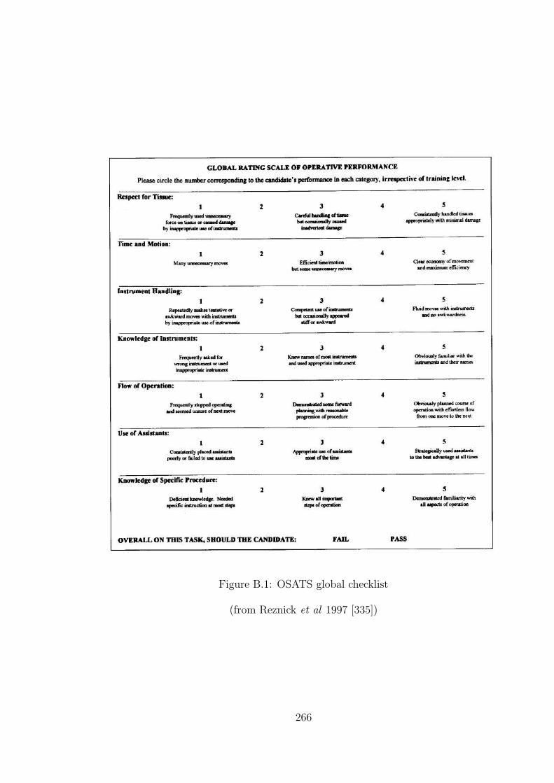
Figure B.1: OSATS global checklist
(from Reznick et al 1997 [335])
266

Figure B.2: OSATS task specific checklist (small bowel anastomosis)
(from Reznick et al 1997 [335])
267

Appendix C
Risk Assessment
268

Appendix D
Evaluation Questionnaire
269

Appendix E
Additional Figures
Note
The data displayed from Test C (Figures E.1 and E.2) comprises nearly all the
‘stitches’ obtained from the SHOs, registrars and consultant surgeons using their
dominant hand (for presentation purposes, the first two ‘stitches’ were removed
from the subject who contributed most data).
The data displayed from Test A (Figures E.3 and E.4) show all ‘stitches’ in every
third trial, starting from the first trial and closing with the last trials of the practice
and retention phases.
In the varied-scale plots, the scales have been automatically selected by software
to match the extents of the data. Refer to the fixed scale plots to see the the actual
region occupied by the data.
270

Strik
e er
ror d
urin
g in
serti
on (s
cale
s va
ry)
Precession error during insertion (scales vary)KE
Y:SH
O
Regi
stra
r
Cons
ulta
nt
Figure E.1: Correlation between errors using Test C results at varied scales
(Note: alternate trials are indicated by circle and square symbols in the plots;coloured triangles indicate the start point of each sequence.)
271

05
10
10 20 30
05
10
10 20 30
05
10
10 20 30
05
10
10 20 30
05
10
10 20 30
05
10
10 20 30
05
10
10 20 30
05
10
10 20 30
05
10
10 20 30
05
10
10 20 30
05
10
10 20 30
05
10
10 20 30
05
10
10 20 30
05
10
10 20 30
05
10
10 20 30
05
10
10 20 30
05
10
10 20 30
05
10
10 20 30
05
10
10 20 30
05
10
10 20 30
05
10
10 20 30
05
10
10 20 30
05
10
10 20 30
05
10
10 20 30
05
10
10 20 30
05
10
10 20 30
05
10
10 20 30
05
10
10 20 30
05
10
10 20 30
05
10
10 20 30
05
10
10 20 30
05
10
10 20 30
05
10
10 20 30
05
10
10 20 30
05
10
10 20 30
05
10
10 20 30
05
10
10 20 30
05
10
10 20 30
05
10
10 20 30
05
10
10 20 30
05
10
10 20 30
05
10
10 20 30
05
10
10 20 30
05
10
10 20 30
05
10
10 20 30
05
10
10 20 30
05
10
10 20 30
05
10
10 20 30
05
10
10 20 30
05
10
10 20 30
05
10
10 20 30
05
10
10 20 30
05
10
10 20 30
05
10
10 20 30
05
10
10 20 30
05
10
10 20 30
05
10
10 20 30
05
10
10 20 30
05
10
10 20 30
05
10
10 20 30
05
10
10 20 30
05
10
10 20 30
05
10
10 20 30
05
10
10 20 30
05
10
10 20 30
05
10
10 20 30
05
10
10 20 30
05
10
10 20 30
05
10
10 20 30
05
10
10 20 30
05
10
10 20 30
05
10
10 20 30
05
10
10 20 30
05
10
10 20 30
05
10
10 20 30
05
10
10 20 30
05
10
10 20 30
05
10
10 20 30
05
10
10 20 30
05
10
10 20 30
05
10
10 20 30Strike error during insertion (degrees)
Prec
essio
n er
ror d
urin
g in
serti
on (d
egre
es)
KEY:SHO
Registrar
Consultant
Figu
reE
.2:C
orrelationbetw
eenerrors
usin
gTest
Cresu
ltsat
fixed
scales
(Note:
alternate
trialsare
indicated
by
circlean
dsq
uare
sym
bols
inth
eplots;
coloured
triangles
indicate
the
startpoin
tof
eachseq
uen
ce.)
272
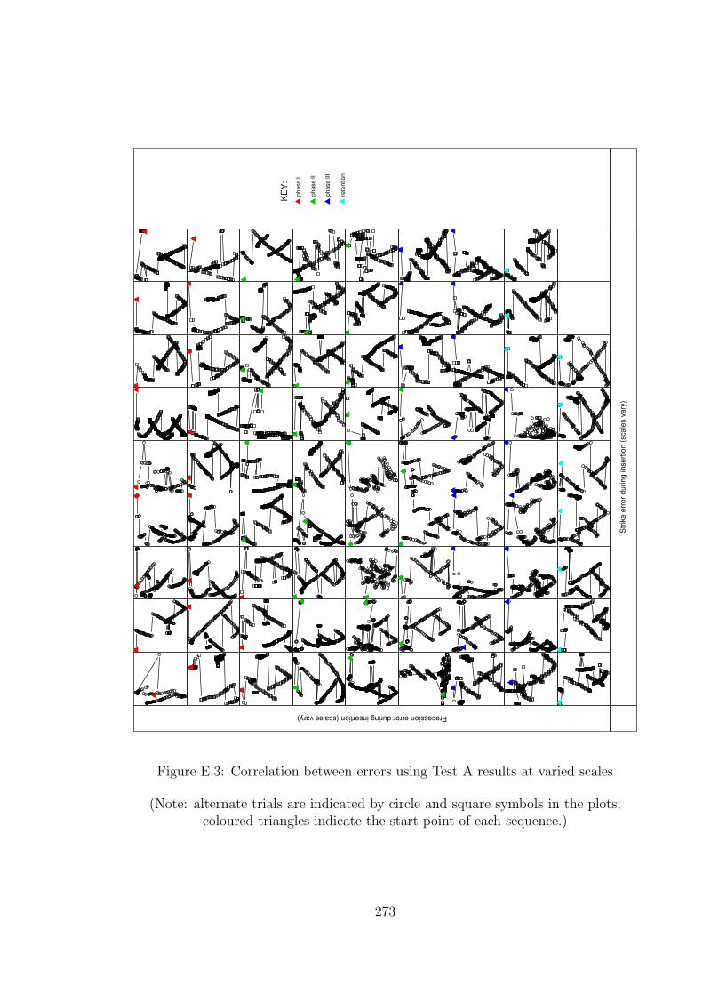
Strik
e er
ror d
urin
g in
serti
on (s
cale
s va
ry)
Precession error during insertion (scales vary)KE
Y:ph
ase
I
phas
e II
phas
e III
rete
ntio
n
Figure E.3: Correlation between errors using Test A results at varied scales
(Note: alternate trials are indicated by circle and square symbols in the plots;coloured triangles indicate the start point of each sequence.)
273

05
10
10 20 30
05
10
10 20 30
05
10
10 20 30
05
10
10 20 30
05
10
10 20 30
05
10
10 20 30
05
10
10 20 30
05
10
10 20 30
05
10
10 20 30
05
10
10 20 30
05
10
10 20 30
05
10
10 20 30
05
10
10 20 30
05
10
10 20 30
05
10
10 20 30
05
10
10 20 30
05
10
10 20 30
05
10
10 20 30
05
10
10 20 30
05
10
10 20 30
05
10
10 20 30
05
10
10 20 30
05
10
10 20 30
05
10
10 20 30
05
10
10 20 30
05
10
10 20 30
05
10
10 20 30
05
10
10 20 30
05
10
10 20 30
05
10
10 20 30
05
10
10 20 30
05
10
10 20 30
05
10
10 20 30
05
10
10 20 30
05
10
10 20 30
05
10
10 20 30
05
10
10 20 30
05
10
10 20 30
05
10
10 20 30
05
10
10 20 30
05
10
10 20 30
05
10
10 20 30
05
10
10 20 30
05
10
10 20 30
05
10
10 20 30
05
10
10 20 30
05
10
10 20 30
05
10
10 20 30
05
10
10 20 30
05
10
10 20 30
05
10
10 20 30
05
10
10 20 30
05
10
10 20 30
05
10
10 20 30
05
10
10 20 30
05
10
10 20 30
05
10
10 20 30
05
10
10 20 30
05
10
10 20 30
05
10
10 20 30
05
10
10 20 30
05
10
10 20 30
05
10
10 20 30
05
10
10 20 30
05
10
10 20 30
05
10
10 20 30
05
10
10 20 30
05
10
10 20 30
05
10
10 20 30
05
10
10 20 30
05
10
10 20 30
05
10
10 20 30
05
10
10 20 30
05
10
10 20 30
05
10
10 20 30
05
10
10 20 30
05
10
10 20 30
05
10
10 20 30
05
10
10 20 30Strike error during insertion (degrees)
Prec
essio
n er
ror d
urin
g in
serti
on (d
egre
es)
KEY:phase I
phase II
phase III
retention
Figu
reE
.4:C
orrelationbetw
eenerrors
usin
gTest
Aresu
ltsat
fixed
scales
(Note:
alternate
trialsare
indicated
by
circlean
dsq
uare
sym
bols
inth
eplots;
coloured
triangles
indicate
the
startpoin
tof
eachseq
uen
ce.)
274

Bibliography
[1] http://www.slnmapping.org. 14-07-04.
[2] http://www.fcs-cs.com/robotics/products/hapticmaster. 09-08-2004.
[3] www.spss.com. 10-10-2004.
[4] www.tgs.com. 11-10-2004.
[5] Ascension Technology Corporation (electromagnetic tracking devices).
http://www.ascension.com.
[6] AutoCAD R.12 AutoDesk Inc. www.autodesk.com.
[7] Corel Draw. www.corel.com.
[8] Haptica Inc. (Boston, MA, USA). http://www.haptica.com. 29-04-2005.
[9] http://www.sense8.com/.
[10] Immersion Medical (Gaithersburg, MD, USA). http://www.immersion.com.
[11] Medicines and Healthcare products Regulatory Agency (MHRA).
http://www.medical-devices.gov.uk. 27-07-2004.
[12] Mentice (Gothenburg, Sweden). http://www.mentice.com. 12-04-2005.
[13] The prism guide to interpreting statistical results.
www.graphpad.com/articles/interpret/ANOVA/repeated measures.htm. 31-
10-2004.
[14] RAPID Collision detection library.
http://www.cs.unc.edu/˜geom/OBB/OBBT.html. 28-10-2003.
[15] Royal college of surgeons of edinburgh. http://www.edu.rcsed.ac.uk. 21-09-
2004.
275

[16] Simbionix (Cleveland, OH, USA). http://www.simbionix.com. 12-04-2005.
[17] SimSurgery AS (Oslo, Norway). http://www.simsurgery.no. 12-04-2005.
[18] Surgical Science (Gothenburg, Sweden). http://www.surgicalscience.com. 12-
04-2005.
[19] Surgical tutor on line. http://www.surgical-tutor.org.uk/default-home.htm.
21-09-2004.
[20] Suture tutor. www.medicalskills.com, 2001.
[21] Verefi Technologies Ltd (Hershey, PA). http://www.verefi.com/. 26-04-2005.
[22] Xitact (Morges, Switzerland). http://www.xitact.com. 29-04-2005.
[23] Working group on specialist medical training. hospital doctors: training for
the future. Department of Health, London, 1993.
[24] HT Medical. http://www.ht.com, 2001.
[25] Immersion Corporation (San Jose, CA, USA).
http://www.immersion.com/medical.html, 2001.
[26] Reach In (Stockholm, Sweden). http://www.reachin.se/Medical, 2001.
[27] VESTA.
http://robotics.eecs.berkeley.edu/˜tendick/tissue.html, 2001. 08-06-04.
[28] 3D Connection. http://www.3dconnexion.com, 2004.
[29] J. Ackerman. http://www.cs.unc.edu/˜us, 2000.
[30] P.L. Ackerman. Predicting individual differences in complex skill acquisition:
Dynamis of ability determinants. Journal of Applied Psychology, 77:598–614,
1992.
[31] J.A. Adams. Historical review and appraisal of research on learning, retention,
and transfer of human motor skills. Psychological Bulletin, 101(1):41–74, 1987.
[32] R. Aggarwal, K. Moorthy, and A. Darzi. Laparoscopic skills training and
assessment. British Journal of Surgery, 91:1549–1558, 2004.
276
[33] M. Agus, A. Giachetti, E. Gobbetti, G. Zanetti, and A. Zorcolo. Tracking the
movement of surgical tools in a virtual temporal bone dissection simulator.
In N. Ayache and H. Delingette, editors, Surgery Simulation and Soft Tissue
Modeling, International Symposium, IS4TM 2003, Proceedings, volume 2673
of Lecture Notes in Computer Science, pages 100–107, Juan-Les-Pins, France,
June 2003. Springer-Verlag.
[34] G. Ahlberg, T. Heikkinen, L. Iselius, C-E. Leijonmarck, J. Rutqvist, and
D. Arvidsson. Does training in a virtual reality simulator improve surgical
performance? Surgical Endoscopy, 16(1):126–129, Jan 2002.
[35] R. Alterovitz, J. Pouliot, R. Taschereau, I-C.J. Hsu, and K. Goldberg. Simulat-
ing needle insertion and radioactive seed implantation for prostate brachyther-
apy. In J.D. Westwood, H.M. Hoffman, G.T. Mogel, R. Phillips, R.A. Robb,
and D. Stredney, editors, Medicine Meets Virtual Reality 11, NextMed: Health
Horizon, volume 94 of Studies in Health Technology and Informatics, pages
19–25. IOS Press, 2003.
[36] D.I. Anderson, R.A. Magill, and H. Sekiya. Motor learning as a function of
kr schedule and characteristics of task-intrinsic feedback. Journal of Motor
Behavior, 33(1):59–66, 2001.
[37] E. Anderson, Z. Bai, C. Bischof, S. Blackford, J. Demmel, J. Dongarra,
J. Du Croz, A. Greenbaum, S. Hammarling, A. McKenney, and D. Sorensen.
LAPACK Users’ Guide. Society for Industrial and Applied Mathematics,
Philadelphia, PA, third edition, 1999.
[38] J. Ankersen, A.E. Birkbeck, R.D. Thomson, and P. Vanezis. Puncture resis-
tance and tensile strength of skin simulants. In Proceedings of the Institution
of Mechanical Engineers, volume H, pages 493–501, 1999.
[39] Anonymous. A multimedia arthroscopic simulator of surgical procedures.
Grant reference GR/l28692, Medical Physics and Clinical Engineering,
www.shef.ac.uk/˜mpce/rsch/skats.pdf, 1999. 28-06-04.
[40] J.S. Atherton. Learning curve.
www.dmu.ac.uk/˜jamesa/learning/lerncrv.htm, 2003. 15-10-2004.
[41] A.L. Auffrey, A. Mirabella, and G.L. Siebold. Transfer of training revisited.
Technical Report RN2001-10, The U.S. Army Research Institute for the Be-
277

havioral and Social Sciences, Eisenhower Avenue, Alexandria, VA, Oct’99-
Jun’01 2001.
[42] R.S. Avila and L.M. Sobierajski. A haptic interaction method for volume
visualization. In Proceedings of Visualization ’96, pages 197–204. GE Corp
Research and Development, 1996.
[43] F.S. Azar, D.N. Metaxas, and R.T. Miller M.D. Schnall. Methods for pre-
dicting mechanical deformations in the breast during clinical breast biopsy. In
Proceedings of the IEEE 26th Annual Northeast Bioengineering Conference,
2000, pages 63–64, Storrs, CT, USA, 2000.
[44] T. Baguley. An introduction to sphericity.
www-staff.lboro.ac.uk/˜hutsb/Spheric.htm. 13-10-2004.
[45] R. Balakrishnan and K. Hinckley. Symmetric bimanual interaction. In Pro-
ceedings of the CHI Conference on Human Factors in Computing Systems,
pages 33–40. ACM Press, 2000.
[46] R. Balaniuk and K. Salisbury. Soft-tissue simulation using the radial elements
method. In N. Ayache and H. Delingette, editors, Proceedings of Surgery Sim-
ulation and Soft Tissue Modeling, International Symposium (IS4TM 2003),
volume 2673 of Lecture Notes in Computer Science, pages 48–58. Springer,
2003.
[47] S. Bann, K.-F. Kwok, C.-Y. Lo, A.Darzi, and J. Wong. Objective assessment
of technical skills of surgical trainees in hong kong. British Journal of Surgery,
90:1294–1299, 2003.
[48] S.D. Bann, M.S. Khan, and A.W. Darzi. Measurement of surgical dexter-
ity using motion analysis of simple bench tasks. World Journal of Surgery,
27(4):390–394, April 2003.
[49] R. Baron. www.airlinesafety.com/index.html. 04-07-2004.
[50] L. Bartoli, G. Spagolla, and C. Robazza. Variability effects on retention of a
motor skill in elementary school children. Perceptual and Motor Skills, 93:51–
63, 2001.
[51] L.M. Batteau, A. Liu, J.B.A. Maintz, Y. Bhasin, and M.W. Bowyer. A study
on the perception of haptics in surgical simulation. In S. Cotin and D.N.
278

Metaxas, editors, Medical Simulation: International Symposium (ISMS 2004),
volume 3078 of Lecture Notes in Computer Science, pages 185–192. Springer,
2004.
[52] BDI. http://www.bdi.com, 2001.
[53] S.L. Beilock, T.H. Carr, C. MacMahon, and J.L. Starkes. When paying atten-
tion becomes counterproductive: Impact of divided versus skill-focused atten-
tion on novice and experienced performance of sensorimotor skills. Journal of
Experimental Psychology: Applied, 8(1):6–16, 2002.
[54] L. Bencini and L.J. Sanchez. Learning curve for laparoscopic ventral hernia
repair. The American Journal of Surgery, 187:378–382, 2004.
[55] S. Bennett, K. Davids, and J. Woodcock. Structural organization of practice:
Effects of practicing under different informational constraints on the acqui-
sition of a one-handed catching skill. Journal of Motor Behavior, 31(1):3–9,
1999.
[56] A. Berger. Trust me, I’m a surgeon. British Medical Journal, 320(7239):948,
April 2000.
[57] J. Berkley, G. Turkiyyah, D. Berg, M. Ganter, and S. Weghorst. Real-time
finite element modeling for surgery simulation: An application to virtual su-
turing. In IEEE Transactions on Visualization and Computer Graphics, vol-
ume 10, pages 1–12, May/June 2004.
[58] J. Berkley, S. Weghorst, H. Gladstone, G. Raugi, D. Berg, and M. Ganter.
Banded matrix approach to finite element modelling for soft tissue simulation.
Virtual Reality, 4(3):203–212, 1999.
[59] S. Bhat, C. Mehta, C. D’Souza, and T.Kesavadas. 3D Real-time FEM based
guide wire simulator with force feedback. In J.D. Westwood, R.S. Haluck, H.M.
Hoffman, G.T. Mogel, R. Phillips, R.A. Robb, and K.G. Vosburgh, editors,
Medicine Meets Virtual Reality 13, The Magical Next Becomes the Magical
Now, volume 111 of Studies in Health Technology and Informatics, pages 50–
53. IOS Press, 2005.
[60] O.S. Bholat, R.S. Haluck, W.B. Murray, P.J. Gorman, and T.M. Krummel.
Tactile feedback is present during minimally invasive surgery. Journal of the
American College of Surgeons, 189:349–355, 1999.
279
[61] D. Bielser and M.H. Gross. Interactive simulation of surgical cuts. In Proceed-
ings of the Eighth Pacific Conference on Computer Graphics and Applications,
2000, pages 116–125,442. IEEE, October 2000.
[62] D. Bielser, V.A. Maiwald, and M.H. Gross. Interactive cuts through 3-
dimensional soft tissue. In P. Brunet and R. Scopigno, editors, Computer
Graphics Forum (Eurographics ’99), volume 18, pages 31–38. The Eurograph-
ics Association and Blackwell Publishers, 1999.
[63] J.W. Bing. The relationship between process and performance on teams.
http://www.itapintl.com/relationshipbetweenteamprocessandperformance.htm.
20-11-2004.
[64] H. Bogaerts and S.P. Swinnen. Spatial interactions during bimanual coor-
dination patterns: The effect of directional compatibility. Motor Control,
2:183–199, 2001.
[65] J.A. Boldovici, D.W. Bessemer, and A.E. Bolton. The elements of training
evaluation. Technical Report BK2002-01, The U.S. Army Research Institute
for the Behavioral and Social Sciences, Eisenhower Avenue, Alexandria, VA,
2002. Compiled Jan’99-Jan’01.
[66] J. Booth. Doctors punished for kidney blunder. January 2004.
society.guardian.co.uk/nhsperformance/story/0,8150,1130246,00.html.
[67] G. Bradshaw, H. Taylor, G. Lintern, and D. Talleur. The potential of sub-
jective estimates of transfer. Technical Report ARL-99-6, Aviation Research
Lab, Dayton, OH, May 1999.
[68] J.D. Brederson, M. Ikits, C. Johnson, and C. Hansen. The visual hap-
tic workbench. In Fifth PHANToM Users Group Workshop, pages 46–49.
http://www.sci.utah.edu/pubs/, 2000.
[69] M. Brehmer and D.A. Tolley. Validation of a bench model for endoscopic
surgery in the upper urinary tract. European Urology, 42:175–180, 2002.
[70] P.N. Brett and R.S.W. Stone. A technique for measuring contact force distri-
bution in minimally invasive surgical procedures. In Proceedings of the Insti-
tution of Mechanical Engineers, volume H, pages 309–316, Bristol, September
1997. 2nd International Workshop on Mechatronics in Medicine and Surgery.
280
[71] M. Bro-Nielsen. Surgery simulation using fast finite elements. In K.H.
Hohne and R. Kinikis, editors, 4th International Conference of Visualization
in Biomedical Computing (VBC’96), pages 529–534, 1996.
[72] M. Bro-Nielsen. Finite element modeling in surgery simulation. Proceedings
of the IEEE, 86(3):490–503, March 1998.
[73] M. Bro-Nielsen and S. Cotin. Real-time volumetric deformable models for
surgery simulation using finite elements and condensation. In Eurographics’96,
Computer Graphics Forum, volume 15, pages 57–66, 1996.
[74] M. Bro-Nielsen, J.L. Tasto, R. Cunningham, and G.L. Merril. PreOp endo-
scopic simulator: A PC-based immersive training system. In Medicine Meets
Virtual Reality 7, San Fransisco, California, 1999. IOS Press.
[75] K. Brodlie, N. El-Khalili, and Y. Li. Using web-based computer graphics to
teach surgery. Computers and Graphics, 24:157–161, 2000.
[76] D. Broe, P.F. Ridgway, S. Johnson, C. Tierney, and K.C. Conlon. Valida-
tion of a novel hybrid surgical simulator. http://www.haptica.com/id25.htm
(abstract nr.: O012). 29-04-2005.
[77] I. Brouwer, J. Ustin, L. Bentley, A. Sherman, N. Dhruv, and F. Tendick.
Measuring in vivo animal soft tissue properties for haptic modeling in surgical
simulation. In J.D. Westwood, H.M. Hoffman, G.T. Mogel, D. Stredney, and
R.A. Robb, editors, Medicine Meets Virtual Reality 2001, volume 81 of Studies
in Health Technology and Informatics, pages 69–74. IOS Press, January 2001.
[78] J. Brown, K. Montgomery, J. Latombe, and M. Stephanides. A microsurgery
simulation system. In Fourth International Conference on Medical Image Com-
puting and Computer-Assisted Intervention (MICCAI 2001), Utrecht, The
Netherlands, October 2001.
http://biocomp.stanford.edu/papers/miccai/01/joel micro miccai01.pdf. 16-
05-2005.
[79] J. Brown, S. Sorkin, C. Bruyns, J.C. Latombe, K. Montgomery, and
M. Stephanides. Real-time simulation of deformable objects: Tools and ap-
plication. In Proceedings of the Computer Animation 2001, Seoul, Korea,
November 2001.
http://biocomp.stanford.edu/papers/ca/01/ca-001 brown.pdf. 16-05-2005.
281

[80] J. Brown, S. Sorkin, J-C. Latombe, K. Montgomery, and M. Stephanides. Al-
gorithmic tools for real-time microsurgery simulation. Medical Image Analysis,
6:289–300, 2002.
[81] C.D. Bruyns and K. Montgomery. Generalized interactions using virtual tools
within the Spring framework. In J.D. Westwood, H.M. Hoffman, R.A. Robb,
and D. Stredney, editors, Medicine Meets Virtual Reality 02/10, volume 85 of
Studies in Health Technology and Informatics, pages 74–78. IOS Press, 2002.
[82] G.C Burdea. Force and Touch Feedback for Virtual Reality. John Wiley and
Sons, Inc., 1996.
[83] G.C. Burdea. Haptics issues in virtual environments. In Proceedings of Com-
puter Graphics International, pages 295–302, 2000.
[84] J. Burki-Cohen, E. Boothe, N. Soja, R. DiSario, T. Go, and T. Longridge.
Simulator fidelity: The effect of platform motion. In Proceedings of the In-
ternational Conference Flight Simulation–The Next Decade, pages 23.1–23.7,
London, UK, May 2000. Royal Aeronautical Society.
[85] J. Burki-Cohen, T.H. Go, W.W. Chung, J. Schroeder, S. Jacobs, and T. Lon-
gridge. Simulator fidelity requirements for airline pilot training and evaluation
continued: an update on motion requirements research. In 12th International
Symposium on Aviation Psychology, pages 1–8, Dayton, OH, USA, April 2003.
16-05-2005.
[86] Z.L. Cai, J. Dill, and S. Payandeh. Toward deformation modeling with haptic
feedback. In Proceedings of the ASME Symposium on Haptic Interface for
Virtual Environment and Tele-Operation, Nashville, USA, November 2000.
The American Society of Mechanical Engineers.
[87] C.F. Camerer, T-H. Ho, and J.K. Chong. Behavioral game theory: Thinking,
learning, and teaching.
www.hss.caltech.edu/˜camerer/Camerer.pdf, November 2001. 15-10-2004.
[88] E.G. Carmines and R.A. Zeller. Reliability and Validity Assessment. Quanti-
tative applications in the social sciences 17. SAGE Publications Inc., Berverly
Hills, CA, USA, 1979.
282
[89] T.R. Carretta and R.D. Dunlap. Transfer of training effectiveness in flight
simulation: 1986 to 1997. Technical Report AFRL-HE-AZ-TR-1998-0078, U.S.
Air Force Research Laboratory, Mesa, AZ, September 1998.
[90] F.J. Carter, T.G. Frank, P.J. Davies, D. McLean, and A. Cuschieri. Measure-
ments and modelling of the compliance of human and porcine organs. Medical
Image Analysis, 5(4):231–236, December 2001.
[91] F.B. Casson and C. Laugier. Modelling the dynamics of a human liver for a
minimally invasive surgery simulator. In Medical Image Computing and Com-
puter Aided Intervention 1999 (MICCAI’99), volume 1679 of Lecture Notes in
Computer Science, pages 1156–1165. Springer, 1999.
[92] M.C. Cavusoglu, T.G. Goktekin, F. Tendick, and S. Sastry. GiPSi: An open
source/open architecture software development framework for surgical simula-
tion. In J.D. Westwood, R.S. Haluck, H.M. Hoffman, G.T. Mogel, R. Phillips,
and R.A. Robb, editors, Medicine Meets Virtual Reality 12, Building a Better
You: The Next Tools for Medical Education, Diagnosis and Care, volume 98 of
Studies in Health Technology and Informatics, pages 46–48. IOS Press, 2004.
[93] H.R. Champion and A.G. Gallagher. Surgical simulation - a good idea whose
time has come. British Journal of Surgery, 90(7):767–768, 2003.
[94] T.R. Chandrupatla and A.D. Belegundu. Introduction to Finite Elements in
Engineering. Prentice Hall, 2nd edition, 1997.
[95] A. Chaudhry, C. Sutton, J.Wood, R. Stone, and R. McCloy. Learning rate for
laparoscopic surgical skills on MIST-VR, a virtual reality simulator: quality
of human-computer interface. Annals of the Royal College of Surgeons of
England, 81:281–286, 1999.
[96] S. Chiviakowsky and G. Wulf. Self-controlled feedback: Does it enhance learn-
ing because performers get feedback when they need it? Research Quarterly
for Exercise and Sport, 73:408–415, 2002.
[97] K. Choi, H. Sun, and P. Heng. Interactive deformation of soft tissues with
haptic feedback for medical learning. IEEE Transactions on information tech-
nology in biomedicine, 7(4):358–363, December 2003.
[98] K.S. Choi, H. Sun, P.A. Heng, and J.C.Y. Cheng. A scalable force propagation
approach for web-based deformable simulation of soft tissues. In WEB3D,
283

Proceedings of the seventh international conference on 3D Web technology,
pages 185–193. ACM Press, 2002.
[99] C.K. Chong, J. Brennan, T.V. How, R. Edwards, G.L. Gilling-Smith, and
P.L. Harris. A prototype simulator for endovascular repair of abdominal
aortic aneurysms. European Journal of Vascular and Endovascular Surgery,
13(3):330–333, 1997.
[100] C.K. Chong, T.V. How, R.A. Black, A.P. Shortland, and P.L. Harris. Devel-
opment of a simulator for endovascular repair of abdominal aortic aneurysms.
Annals of Biomedical Engineering, 26(5):798–802, 1998.
[101] P.C. Chou and N.J. Pagano. Elasticity: Tensor, Dyadic and Engineering
Approaches. Dover Publications, Inc., 1967.
[102] D. Clark. Yerkes-Dodson law - Arousal (01-12-1999).
http://www.nwlink.com/˜donclark/hrd/history/arousal.html.
[103] D. M. Clawson, A.F. Healy, K.A. Ericsson, and L.E. Bourne Jr. Retention and
transfer of morse code reception skill by novices: Part-whole training. Journal
of Experimental Psychology: Applied, 7(2):129–142, 2001.
[104] J. Cohen. Statistical Power Analysis for the Behavioural Sciences. Lawrence
Erlbaum Associates, Inc., 2nd edition, 1977.
[105] J.E. Colgate, P.E. Grafing, M.C. Stanley, and G. Schenkel. Implementation of
stiff virtual walls in force-reflecting interfaces. In Virtual Reality Annual In-
ternational Symposium, 1993. 1993 IEEE, pages 202–208, Seattle, WA, USA,
September 1993. IEEE.
[106] R.D. Cook, D.S. Malkus, M.E. Plesha, and R.J. Watt. Concepts and Applica-
tions of Finite Element Analysis. Wiley, New York, 4th edition, 2002.
[107] P.H. Cosman, P.C. Cregan, and J.A. Cartmill. Quantifying surgical skill:
Chirometrics. ANZ Journal of Surgery, 72(Supplement 1:A101), May 2002.
[108] P.H. Cosman, P.C. Cregan, C.J. Martin, and J.A. Cartmill. Virtual reality
simulators: Current status in acquisition and assessment of surgical skills.
ANZ Journal of Surgery, 72:30–34, 2002.
284

[109] P.H. Cosman, R. Hawkins, M.A. Hutchins, P.C. Cregan, and J.A. Cartmill.
Construct validity of a novel laparoscopic simulator: Early results. ANZ Jour-
nal of Surgery, 72 (Suppl.):A98, 2002.
[110] I.F. Costa and R. Balaniuk. LEM - An approach for physically based soft
tissue simulation suitable for haptic interaction. In Proceedings of the Fifth
PHANTOM Users Group Workshop, October, 2000, Aspen, USA, October
2000. PUG2000.
[111] S. Cotin, H. Delingette, and N. Ayache. Real time volumetric models for
surgery simulation. In K.H. Hohne and R. Kinikis, editors, 4th International
Conference of Visualization in Biomedical Computing (VBC’96), pages 535–
540, 1996.
[112] S. Cotin, H. Delingette, and N. Ayache. Real-time elastic deformations of soft
tissues for surgery simulation. Technical Report RR-3511, INRIA, 1998.
[113] S. Cotin, H. Delingette, and N. Ayache. A hybrid elastic model for real-time
cutting, deformations, and force feedback for surgery training and simulation.
The Visual Computer, 16(8):437–452, 2000.
[114] S.A. Cover, N.F. Ezquerra, J.F. O’Brien, R. Rowe, T. Gadacz, and E. Palm. In-
teractively deformable models for surgery simulation. IEEE Computer Graph-
ics and Applications, 13(6):68–75, 1993.
[115] C.E. Cox, S.S. Bass, D. Boulware, N.K. Ku, C. Berman, and D.S. Reintgen.
Implementation of new surgical technology: Outcome measures for lymphatic
mapping of breast carcinoma. Annals of Surgical Oncology, 6(6):553–561, 1999.
[116] C.E. Cox, C.J. Salud, A. Cantor, S.S. Bass, E.S. Peltz, M.D. Ebert, K. Nguyen,
and D.S. Reintgen. Learning curves for breast cancer sentinel lymph node
mapping based on surgical volume analysis. Journal of the American College
of Surgery, 193(6):593–600, December 2001.
[117] J.P. Coxon, S.H. Pattison, J.W. Parks, P.K. Stevenson, and R.S. Kirby. Re-
ducing human error in urology: Lessons from aviation. British Journal of
Urology International, 91:1–3, January 2003.
[118] A. Crossan. The Design and Evaluation of a Haptic Veterinary Palpation
Training Simulator. PhD thesis, Department of Computing Science and Fac-
ulty of Veterinary Medicine, University of Glasgow, December 2003.
285

[119] A. Crossan, S.A. Brewster, and S. Reid. Multi-session VR medical training -
the HOPS simulator. In Proceedings of the 16th British HCI Group Annual
Conference, pages 213–226, London, September 2002. BCS HCI, Springer.
[120] A. Crossan, S.A. Brewster, S. Reid, and D. Mellor. Comparison of simulated
ovary training over different skill levels. In Proceedings of Eurohaptics, pages
17–21, Birmingham, UK, 2001.
[121] J.J. Du Croz and N.J. Higham. Stability of methods for matrix inversion. IMA
Journal of Numerical Analysis, 12:1–19., January 1992.
[122] A. Cuschieri. Wither minimal access surgery? tribulations and expectations.
The American Journal of Surgery, 169:9–19, 1995.
[123] A. Cuschieri et al. Metrics final report: Objective assessment of
surgical skills workshop. Technical report, Accreditation Council of
Graduate Medical Education, American Board of Medical Specialties,
American Board of Surgery and National Board of Medical Exam-
iners, Mountain Shadows Resort, Scottsdale, AZ, USA, July 2001.
http://matmo.org/website metrics/metrics final/finalreport.html. 11-12-01.
[124] L.D. Cutler, B. Frolich, and P. Hanrahan. Two-handed direct manipulation on
the responsive workbench. In Symposium on Interactive 3D Graphics, pages
107–114, 191, 1997.
[125] A. Darzi, V. Datta, and S. Mackay. The challenge of objective assessment of
surgical skill. The American Journal of Surgery, 181:484–486, 2001.
[126] V. Datta, A. Chang, S. Mackay, and A. Darzi. The relationship between
motion analysis and surgical technical assessments. The American Journal of
Surgery, 184(1):70–73, July 2002.
[127] D. d’Aulignac, C. Laugier, and R. Balaniuk. A haptic interface for a virtual
exam of the human thigh. In Proceedings of IEEE International Conference
on Robotics and Automation (ICRA ’00), volume 3, pages 2452–2457, San
Francisco, CA, USA, April 2000. IEEE.
[128] S. De and K.J. Bathe. The method of finite spheres: a summary of recent
developments. In First MIT Conference on Computational Fluid and Solid
Mechanics, pages 1546–1549. MIT, Elsevier Science, 2001.
286
[129] S. De, J. Kim, and M.A. Srinivasan. Virtual surgery simulation using a
collocation-based method of finite spheres. In K.J. Bathe, editor, First MIT
Conference on Computational Fluid and Solid Mechanics, pages 140–141. MIT,
Elsevier Science Ltd, 2001.
[130] F. Debaere, N. Wenderoth, S. Sunaert, P. Van Hecke, and S.P. Swinnen. Inter-
nal vs external generation of movements: differential neural pathways involved
in bimanual coordination performed in the presence or absence of augmented
visual feedback. NeuroImage, 19:764–776, 2003.
[131] H. Delingette. Towards realistic soft tissue modeling in medical simulations.
Technical Report RR-3506, INRIA, 1998.
[132] N.J. Delson, N. Koussa, R.H. Hastings, and M.B. Weinger. Quantifying ex-
pert vs novice skill in vivo for development of a laryngoscopy simulator. In
J.D. Westwood, H.M. Hoffman, G.T. Mogel, R. Phillips, R.A. Robb, and
D. Stredney, editors, Medicine Meets Virtual Reality 11: The Next Genera-
tion, volume 94 of Studies in Health Technology and Informatics, pages 45–51.
IOS Press, January 2003.
[133] A.M. Derossis, D.A. DaRosa, S. Dutta, and G.L. Dunnington. A ten-year
analysis of surgical education research. The American Journal of Surgery,
180:58–61, July 2000.
[134] M. Desbrun, P. Schroder, and A. Barr. Interactive animation of structured de-
formable objects. In Computer Graphics, Proceedings of the Annual Graphics
Interface ’99, number 5, pages 73–77, Kingston, Canada, June 1999.
[135] O. Deussen, L. Kobbelt, and P. Tucke. Using simulated annealing to ob-
tain good nodal approximations of deformable bodies. In D. Terzopoulos and
D. Thalmann, editors, Computer Animation and Simulation ’95: Proceedings
of the Sixth Eurographics Workshop on Simulation and Animation, pages 1–14,
Maastricht, September 1995. Springer.
[136] S.P. DiMaio and S.E. Salcudean. Needle insertion modelling and simulation.
In International Conference on Robotics and Automation (ICRA 2002), pages
2098–2105, Washington DC, May 2002. IEEE.
287

[137] E.K. Dimitriadis, F. Horkay, J. Maresca, B. Kachar, and R.S. Chadwick. De-
termination of elastic moduli of thin layers of soft material using the atomic
force microscope. Biophysical Journal, 82(5):2798–2810, May 2002.
[138] S.M. Doane, D.L. Alderton, Y.W. Sohn, and J.W. Pellegrino. Acquisition
and transfer of skilled performance: Are visual discrimination skills stimulus
specific. Journal of Experimental Psychology: Human Perception and Perfor-
mance, 22:1218–1248, 1996.
[139] L. Donaldson. Unfinished business: Proposals for modernising medical careers.
Technical report, Chief Medical Officer, Department of Health, 2003.
[140] A.J. Duffy, N.J. Hogle, J.I. Lew H. McCarthy, A. Egan, P. Christos, and D. L.
Fowler. Construct validity for the LAPSIM laparoscopic surgical simulator.
Surgical Endoscopy, Published online: 23 December 2004, 2004.
[141] D.M. Ebenstein, A. Kuo, J.J. Rodrigo, A.H. Reddi, M. Ries, and L. Pruitt. A
nanoindentation technique for functional evaluation of cartilage repair tissue.
Journal of Materials Research, 19(1):274–281, 2004.
[142] M. Edwards and P.Trigwell. Prime skills in surgery. www.scalpelfax.com,
1999.
[143] M. Edwards and P. Trigwell. Current techniques in surgery: A new universal
language, a new literature, and a new multimedia training tool for operative
surgery on cd-rom. In C. McBeath and R. Atkinson, editors, Proceedings of the
Third International Interactive Multimedia Symposium, pages 119–122, Perth,
Western Australia, January 1996. 3rd International Interactive Multimedia
Symposium.
[144] N. El-Khalili. Surgical Training on the World Wide Web. PhD thesis, School
of Computing, University of Leeds, Leeds, UK, 1999.
[145] N. El-Khalili and K.W. Brodlie. Surgical training on the web. Future Gener-
ation Computer Systems, 17:147–158, 2000.
[146] M.A. ElHelw, A.J. Chung, A. Darzi, and G-Z. Yang. Image-based modelling of
soft tissue deformation. In R.E. Ellis and T.M. Peters, editors, Medical Image
Computing and Computer Aided Intervention (MICCAI’2003), volume 2878
of Lecture Notes in Computer Science, pages 83–90. Springer-Verlag, Berlin,
2003.
288
[147] M.A. ElHelw, B.P. Lo, A.J. Chung, A. Darzi, and G-Z. Yang. Photorealistic
rendering of large tissue deformation for surgical simulation. In C. Barillot,
D.R. Haynor, and P. Hellier, editors, Medical Image Computing and Com-
puter Aided Intervention (MICCAI’2004), volume 3217 of Lecture Notes in
Computer Science, pages 355–362. Springer-Verlag, Berlin, 2004.
[148] K.A. Ericsson, R.T. Krampe, and C. Tesch-Romer. The role of deliber-
ate practice in the acquisition of expert performance. Psychological Review,
100(3):363–406, 1993.
[149] R.Q. Erkamp, P. Wiggins, A.R. Skovoroda, S.Y. Emelianov, and M. O’Donnell.
Measuring the elastic modulus of small tissue samples. Ultrasonic Imaging,
20(1):17–28, January 1998.
[150] L. Fabiani, G. Burdea, N. Langrana, and D. Gomez. Human interface using
the rutgers master ii force feedback interface. In Proceedings of the IEEE
1996 Virtual Reality Annual International Symposium (VRAIS), pages 54–59.
IEEE, April 1996.
[151] M.J. Fagan. Finite Element Analysis. Prentice Hall, 1992.
[152] A. Faraci, F. Bello, and A. Darzi. Soft tissue deformation using a hierarchical
finite element model. In J.D. Westwood, R.S. Haluck, H.M. Hoffman, G.T.
Mogel, R. Phillips, and R.A. Robb, editors, Medicine Meets Virtual Reality
12, Building a Better You: The Next Tools for Medical Education, Diagnosis
and Care, volume 98 of Studies in Health Technology and Informatics, pages
92–98. IOS Press, 2004.
[153] A. Faraci, F. Bello, and A. Darzi. Soft tissue deformation using a nonlinear
hierarchical finite element model with real-time online refinement. In J.D.
Westwood, R.S. Haluck, H.M. Hoffman, G.T. Mogel, R. Phillips, R.A. Robb,
and K.G. Vosburgh, editors, Medicine Meets Virtual Reality 13, The Magical
Next Becomes the Magical Now, volume 111 of Studies in Health Technology
and Informatics, pages 137–144. IOS Press, 2005.
[154] A. Ferlitsch, P. Glauninger, A. Gupper, M. Schillinger, M. Haefner, A. Gangl,
and R. Schoefl. Evaluation of a virtual endoscopy simulator for training in
gastrointestinal endoscopy. Endoscopy, 34:698–702, 2002.
289
[155] A. Field. A bluffer’s guide to . . . sphericity. (13-10-2004).
http://www.sussex.ac.uk/Users/andyf/research/articles/sphericity.pdf.
[156] A. Field. Discovering Statistics using SPSS for Windows. Sage Publications
Ltd, 2000.
[157] P.L. Figert, A.E. Park, D.B. Witzke, and R.W. Schwartz. Tansfer of training
in acquiring laparoscopic skills. Journal of the American College of Surgeons,
193(5):533–537, November 2001.
[158] P.M. Fitts. The information capacity of the human motor system in controlling
the amplitude of movement. Journal of Experimental Psychology, 47:381–391,
1954.
[159] P.M. Fitts and M.I. Posner. Human Performance. Brooks/Cole Publishing
Company, Belmont, CA, USA, 1967.
[160] N.K. Francis, G.B. Hanna, and A. Cuschieri. Reliability of the advanced
dundee endoscopic psychomotor tester for bimanual tasks. Archives of Surgery,
136(1):40–43, January 2001.
[161] T.B. Frick, D.D. Marucci, J.A. Cartmill, C.J. Martin, and W.R. Walsh. Resis-
tance forces acting on suture needles. Journal of Biomechanics, 34:1335–1340,
2001.
[162] S.F. Frisken-Gibson. Using linked volumes to model object collisions, defor-
mation, cutting, carving, and joining. In IEEE Transactions on Visualization
and Computer Graphics, volume 5, pages 333–348. MERL, 1999.
[163] A. Frisoli, L. Borelli, and M. Bergamasco. Modeling biologic soft tissue for
haptic feedback with a hybrid multiresolution method. In J.D. Westwood, R.S.
Haluck, H.M. Hoffman, G.T. Mogel, R. Phillips, R.A. Robb, and K.G. Vos-
burgh, editors, Medicine Meets Virtual Reality 13, The Magical Next Becomes
the Magical Now, volume 111 of Studies in Health Technology and Informatics,
pages 145–148. IOS Press, 2005.
[164] D. Fu, S.F. Levinson, S.M. Gracewski, and K.J. Parker. Non-invasive quanti-
tative reconstruction of tissue elasticity using an iterative forward approach.
Physics in Medicine and Biology, 45(6):1495–1509, June 2000.
290

[165] H. Fuchs, M.A. Livingston, R. Raskar, D. Colucci, K. Keller, A. State, J.R.
Crawford, P. Rademacher, S.H. Drake, and A.A. Meyer. Augmented reality
visualization for laparascopic surgery. In W.M. Wells III, A.C.F. Colchester,
and S. Delp, editors, Proceedings of Medical Image Computing and Computer-
Assisted Intervention (MICCAI’98), First International Conference, volume
1496 of Lecture Notes in Computer Science, pages 934–943, Cambridge, MA,
USA, October 1998. Springer.
[166] Y.C. Fung. Biomechanics : mechanical properties of living tissues. Imprint
New York London : Springer, 1993.
[167] Ch. Brechbuhler G. Szekely, R. Hutter, A. Rhomberg, N. Ironmonger, and
P. Schmid. Modelling of soft tissue deformation for laparoscopic surgery sim-
ulation. Medical Image Analysis, 4(1):57–66, March 2000.
[168] A.G. Gallagher, E.M. Ritter, H. Champion, G. Higgins, M.P. Fried, G. Moses,
C.D. Smith, and R. Satava. Virtual reality simulation for the operating room:
Proficiency-based training as a paradigm shift in surgical skills training. Annals
of Surgery, 241(2):364–372, February 2005.
[169] A.G. Gallagher and R.M. Satava. Virtual reality as a metric for the assessment
of laparoscopic psychomotor skills. learning curves and reliability measures.
Surgical Endoscopy, 16(12):1746–1752, 2002.
[170] A.G. Gallagher, C.D. Smith, S.P. Bowers, N.E. Seymour, A. Pearson, S. Mc-
Natt, D. Hananel, and R.M. Satava. Psychomotor skills assessment in prac-
ticing surgeons experienced in performing advanced laparoscopic procedures.
Journal of the American College of Surgeons, 197(3):479–488, September 2003.
[171] F. Ganovelli, J. Dingliana, and C. O’Sullivan. Buckettree: Improving collision
detection between deformable objects. In Proceedings of the Spring Conference
in Computer Graphics (SCCG2000), pages 156–163, Bratislava, April 2000.
[172] A. Gawande. Annals of medicine: The learning curve. The New Yorker,
January 2002. pp. 59–60.
[173] A.M. Gentile. Movement Science: Foundations for physical therapy, chapter
Skill Acquisition: Action, movement and neuromotor processes, pages 111–
187. Rockville MD, Aspen, 2nd edition, 2000.
291

[174] S. Gibson, C. Fyock, E. Grimson, T. Kanade, R. Kikinis, H. Lauer, N. McKen-
zie, A. Mor, S. Nakajima, H. Ohkami, R. Osborne, J. Samosky, and A. Sawada.
Volumetric object modeling for surgical simulation. Medical Image Analysis,
2(2):121–132, 1998.
[175] S. Gibson, J. Samosky, A. Mor, C. Fyock, E. Grimson, T. Kanade, R. Kikinis,
H. Lauer, N. McKenzie, S. Nakajima, Ohkami H., R. Osborne, and A. Sawada.
Simulating arthroscopic knee surgery using volumetric object representations,
real-time volume rendering and haptic feedback. In CVRMed-MRCAS ’97:
Proceedings of the First Joint Conference on Computer Vision, Virtual Reality
and Robotics in Medicine and Medial Robotics and Computer-Assisted Surgery,
volume 1205 of Lecture Notes In Computer Science, pages 369–378. Springer-
Verlag, 1997.
[176] S.F.F. Gibson. 3D ChainMail: A fast algorithm for deforming volumetric
objects. In SI3D ’97: Proceedings of the 1997 symposium on Interactive 3D
graphics, pages 149–ff., Providence, Rhode Island, USA, 1997. ACM Press,
New York, NY, USA.
[177] E.G. Gilbert, D.W. Johnson, and S.S. Keerthi. A fast procedure for comput-
ing the distance between complex objects in three-dimensional space. IEEE
Journal of Robotics and Automation, 4(2), April 1988.
[178] E. Gobbetti, M. Tuveri, G. Zanetti, and A. Zorcolo. Catheter insertion simu-
lation with co-registered direct volume rendering and haptic feedback. In J. D.
Westwood, H. M. Hoffman, G. T. Mogel, R. A. Robb, and D. Stredney, editors,
Medicine Meets Virtual Reality, Envisioning Healing: Interactive Technology
and the Patient-Practioner Dialogue, volume 70 of Studies in Health Technol-
ogy and Informatics, pages 96–98. IOS Press, January 2000.
[179] B.P. Goettl. Part-task training of complex tasks. In Proceedings of the 39th
Annual Meeting of the Human Factors and Ergonomics Society, pages 1345–
1349, San Diego, CA, 1995.
[180] B.P. Goettl and V.J. Shute. Analysis of part-task training using the backward-
transfer technique armstrong laboratory, u.s. air force. Journal of Experimental
Psychology: Applied, 2(3):227–249, 1996.
292
[181] M. Gor, R. McCloy, R. Stone, and A. Smith. Virtual reality laparascopic
simulator for assessment in gynaecology. British Journal of Obstetrics and
Gynaecology, 110:181–187, February 2003.
[182] M.S. Gordon, S.B. Issenberg, J.W. Mayer, and J.M. Felner. Developments in
the use of simulators and multimedia computer systems in medical education.
Medical Teacher, 21(1):32–36, 1999.
[183] P.J. Gorman, A.H. Meier, and T.M. Krummel. Simulation and virtual reality
in surgical education - real or unreal? Archives of Surgery, 134(11):1203–1208,
November 1999.
[184] D.A. Gould. The development of a virtual, anatomical model with image
guided interventional training capability.
http://www.rlbuht.nhs.uk, February 2002.
[185] N.K. Govindaraju, S. Redon, M.C. Lin, and D. Manocha. CULLIDE: In-
teractive collision detection between complex models in large environments
using graphics hardware. In Proceedings of ACM SIGGRAPH/Eurographics
Graphics Hardware, 2003. Eurographics Association, 2003.
[186] C. Graeber. Human factors. Aero, 08, October 1999. Produced by Chief
Engineer, Human Factors Engineering, Boeing Commercial Airplanes Group.
[187] T.P. Grantcharov, L. Bardram, P. Funch-Jensen, and J. Rosenberg. Learning
curves and impact of previous operative experience on performance on a virtual
reality simulator to test laparoscopic surgical skills. The American Journal of
Surgery, 185(2):146–149, 2003.
[188] E.D. Grober, S.J. Hamstra, K.R. Wanzel, R.K. Reznick, E.D. Matsumoto, R.S.
Sidhu, and K.A. Jarvi. Validation of novel and objective measures of microsur-
gical skill: Hand-motion analysis and stereoscopic visual acuity. Microsurgery,
23:317–322, 2003.
[189] E.D. Grober, S.J. Hamstra, K.R. Wanzel, R.K. Reznick, E.D. Matsumoto,
R.S. Sidhu, and K.A. Jarvi. The educational impact of bench model fidelity
on the acquisition of technical skill: The use of clinically relevant outcome
measures. Annals of Surgery, 240(2):374–381, August 2004.
293
[190] Y. Guiard. Asymmetric division of labour in human skilled bimanual action:
the kinematic chain as a model. Journal of Motor Behavior, 19(4):486–517,
1987.
[191] M. Haimovici. Haimovici’s Vascular Surgery. Blackwell Science Inc., New
York, 4th edition, 1996.
[192] R. Haluck, R. Webster, D. Zimmerman, E. Mohler, A. Syn-
der, and M. Melkonian. A prototype haptic suturing simulator.
http://cs.millersville.edu/˜webster/ haptics/suture/index.html, July 2001.
16-05-2005.
[193] R.S. Haluck, R.W. Webster, A.J. Snyder, M.G. Melkonian, E.J. Mohler, M.L.
Dise, and A. Lefever. A virtual reality surgical trainer for navigation in laparo-
scopic surgery. In J.D. Westwood, H.M. Hoffman, G.T. Mogel, D. Stredney,
and R.A. Robb, editors, Medicine Meets Virtual Reality (MMVR 2001), vol-
ume 81 of Studies in Health Technology and Informatics, pages 171–176. IOS
Press, 2001.
[194] J.M. Hamdorf and J.C. Hall. Acquiring surgical skills. British Journal of
Surgery, 87:28–37, 2000.
[195] M. Hammerton. Measures for the efficiency of simulators as training devices.
Ergonomics, 10:63–65, 1967.
[196] S.J. Hamstra, D.J. Anastakis, R.S. Sidhu, E.D. Grober, and K.R. Wanzel.
Why visual-spatial ability might be important in surgical training and how to
measure it. Focus on Surgical Education, 20(4):23–25, 2003.
[197] J. Hance, R. Aggarwal, S. Undre, H. Patel, N. Selvapatt, and A. Darzi. Eval-
uation of a laparoscopic video trainer with in-built measures of performance.
In Society of Laparoendoscopic Surgeons 2004 Abstract no. 4111MUL, 2004.
29-04-2005.
[198] D.J. Hand and M.J. Crowder. Practical Longitudinal Data Analysis. Chapman
& Hall, London, 1996.
[199] E.J. Hanly, M.R. Marohn, S.L. Bachman, M.A. Talamini, S.O. Hacker, R.S.
Howard, and N.S. Schenkman. Multiservice laparoscopic surgical training us-
ing the davinci surgical system. The American Journal of Surgery, 187:309–
315, 2004.
294
[200] K.V. Hansen, L. Brix, C.F. Pedersen, J.P. Haase, and O.V. Larsen. Modelling
of interaction between a spatula and a human brain. Medical Image Analysis,
8(1):23–33, March 2004.
[201] C.J. Harris, M. Herbert, and Steele R.J.C. Psychomotor skills of surgical
trainees compared with those of different medical specialists. British Journal
of Surgery, 81:382–383, 1994.
[202] A.E. Healey, J.C. Evans, M.G. Murphy, S. Powell, T.V. How, D. Groves,
F. Hatfield, B.M. Diaz, and D.A. Gould. In vivo force during arterial in-
terventional radiology needle puncture procedures. In J.D. Westwood, R.S.
Haluck, H.M. Hoffman, G.T. Mogel, R. Phillips, R.A. Robb, and K.G. Vos-
burgh, editors, Medicine Meets Virtual Reality 13, The Magical Next Becomes
the Magical Now, volume 111 of Studies in Health Technology and Informatics,
pages 178–184. IOS Press, 2005.
[203] Benjamin E. Hermalin and Alice M. Isen. The effect of affect on economic and
strategic decision making.
[204] D.M. Herrington, W.V. Brown, L. Mosca, W. Davis, B. Eggleston, W.G.
Hundley, and J. Raines. Relationship between arterial stiffness and subclinical
aortic atherosclerosis. Circulation, 110:432–437, 2004.
[205] G.A. Higgins and D.A. Meglan. Teleos: Development of a software toolkit for
authoring virtual medical environments. Presence: Teleoperators & Virtual
Environments, 6(2):241–253, 1997.
[206] K. Hinckley. Haptic Issues for Virtual Manipulation. PhD thesis, University
of Virginia, 1997.
[207] G. Hirota, R. Maheshwari, and M.C. Lin. Fast volume preserving free form
deformation using multilevel optimisation. In SMA ’99: Proceedings of the
fifth ACM symposium on Solid modeling and applications, pages 234–245, New
York, NY, USA, 1999. ACM Press.
[208] K.E. Hoff III, A. Zaferakis, M. Lin, and D. Manocha. Fast and simple 2d geo-
metric proximity queries using graphics hardware. In SI3D: ACM Symposium
on Interactive 3D Graphics, 2001.
[209] R. Holbrey, A. Bulpitt, K. Brodlie, M. Walkley, and J. Scott. A model for vir-
tual suturing in vascular surgery. In P.G. Lever, editor, Theory and Practice of
295
Computer Graphics, pages 50–59, Bournemouth, UK, June 2004. Eurographics
UK, IEEE Computer Society.
[210] R.P. Holbrey and A.J. Bulpitt. Metrics and motion analysis for assessment of
surgical skills. In J.D. Westwood, H.M. Hoffman, G.T. Mogel, R. Phillips, R.A.
Robb, and D. Stredney, editors, Medicine Meets Virtual Reality 11, NextMed:
Health Horizon, volume 94 of Studies in Health Technology and Informatics,
pages 124–126. IOS Press, January 2003.
[211] J.M. Hollerbach. Some current issues in haptics research. In IEEE Interna-
tional Conference Proceedings of ICRA Robotics and Automation, volume 1,
pages 757–762, 2000.
[212] H. Hoppe, T. DeRose, T. DuChamp, J. McDonald, and W. Steutze. Mesh
optimisation. In Proceedings of SIGGRAPH ’93, pages 19–26. ACM Press,
1993.
[213] R.J.A.W. Hosman and H.G. Stassen. Pilot’s perception in the control of air-
craft motions. Control Engineering Practice, 7:1421–1428, 1999.
[214] S.M. Hu, H. Zhang, C.L. Tai, and J. G. Sun. Direct manipulation of ffd:
Efficient explicit solutions and decomposible multiple point constraints. Visual
Computer, 17(6):370–379, 2001.
[215] T.C. Hudson, M.C. Lin, J. Cohen, S. Gottschalk, and D. Manocha. V-
COLLIDE: Accelerated collision detection for VRML. In R. Carey and
P. Strauss, editors, VRML 97: Second Symposium on the Virtual Reality Mod-
eling Language, New York City, NY, 1997. ACM Press.
[216] K.H. Huebner. The finite element method for engineers. Wiley-Interscience,
New York ; London, 1975.
[217] K.C.W. Hui, F. Zhang, W.W. Shaw, Z. Kryger, N.S. Piccolo, A. Harper, and
W.C. Lineaweaver. Learning curve of microvascular venous anastomosis: A
never ending struggle? Microsurgery, 20:22–24, 2000.
[218] TGS Open Inventor. Open inventor from mercury release 5.0 versus sgi open
inventor 2.1. http://www.tgs.com/pro div/oiv vs sgi whitepaper.htm, Dec
2003. (No longer available).
296
[219] D.L. James and D.K. Pai. Artdefo: accurate real time deformable objects. In
SIGGRAPH, Proceedings of the 26th annual conference on Computer Graphics
and Interactive Techniques, pages 65–72, 1999.
[220] D.L. James and D.K. Pai. A unified treatment of elastostatic contact sim-
ulation for real time haptics. Haptics-e, The Electronic Journal of Haptics
Research, 2(1), September 2001.
[221] A.K. Jha, B.W. Duncan, and D.W. Bates. Making Health Care Safer A Critical
Analysis of Patient Safety Practices, chapter 45, pages 511–518. Number 43
in Evidence Report/Technology Assessment. AHRQ Publication, University
of California at San Francisco (UCSF)-Stanford University Evidence-based
Practice Center, 2001.
[222] N. W. John and N. Phillips. Surgical simulators using the WWW. In J. D.
Westwood, H. M. Hoffman, G. T. Mogel, R. A. Robb, and D. Stredney, editors,
Medicine Meets Virtual Reality, volume 70 of Studies in Health Technology and
Informatics, pages 146–152. IOS Press, 2000.
[223] D.M. Johnson and J.E. Stewart II. Utility of a personal computer aviation
training device for flight training. Technical Report RR1787, U.S. Army Re-
search Institute, U.S. Army Research Institute for the Behavioral and Social
Sciences, 5001 Eisenhower Avenue, Alexandria, Virginia, February 2002.
[224] W.R. Johnson. Laparoscopic surgery: time for re-evaluation. Medical Journal
of Australia, 165:355, 1996. Senior Surgeon, Alfred Hospital, Melbourne.
[225] P. Kabbash, W. Buxton, and A. Sellen. Two-handed input in a compound task.
In Proceedings of the SIGCHI conference on Human Factors in Computing
Systems, pages 417–423. ACM Press, 1994.
[226] H. Kajimoto, N. Kawakami, T. Maeda, and S. Tachi. Electro-tactile display
with force feedback. In World Multiconference on Systemics, Cybernetics and
Informatics, pages 95–99, Orlando, Florida, 2001.
[227] N. Katakami, Y. Yamasaki, K. Kosugi, H. Waki, M. Matsuhisa, Y. Kajimoto,
T. Masuyama, and M. Hori. Tissue characterization identifies subjects with
high risk of cardiovascular diseases. Diabetes Research and Clinical Practice,
63(2):93–102, February 2004.
297

[228] A.S. Kaufman. Practice effects. In R.J. Sternberg, editor, Encyclopedia of Hu-
man Intelligence, volume 2, pages 828–833. Macmillan Publishing Company,
http://www.psychologicalforum.com/PDF/practice.pdf, 1994. Extract by
The Gale Group. 29-06-04.
[229] E. Keeve, S. Girod, P. Pfeifle, and B. Girod. Anatomy-based facial tissue
modeling using the finite element method. In R. Yagel and G.M. Nielson,
editors, IEEE Visualization ’96, pages 21–28, 1996.
[230] E. Keeve, S. Girog, R. Kikinis, and B. Girod. Deformable modeling of facial
tissue for craniofacial surgery simulation. Computer Aided Surgery, 3(5):228–
238, 1999.
[231] A.E. Kerdok, S.M. Cotin, M.P. Ottensmeyer, A.M. Galea, R.D. Howe, and
S. L. Dawson. Truth cube: Establishing physical standards for real time soft
tissue simulation. Medical Image Analysis, 7:283–291, 2003.
[232] M.W. Kernodle and L.G. Carlton. Information feedback and the learning of
multiple degree-of-freedom activities. Journal of Motor Behavior, 24(2):187–
196, 1992.
[233] K. Kilty. Design your experiments Part XIV: Quasi-experiments.
http://www.sas.org/E-bulletin/2002-03-15/featrues/body.html. 02-08-2004.
[234] P.J. King, A.P.and Edwards, C.R. Maurer Jr, D.A. de Cunha, R.P. Gacton,
M. Clarkson, D.L.G. Hill, D.J. Hawkes, M.R. Fenlon, A.J. Strong, T.C.S.
Cox, and M.J. Gleeson. Stereo augmented reality in the surgical microscope.
Presence: Teleoperators & Virtual Environments, 9(4):360–369, August 2000.
[235] M. Kitagawa, D. Dokko, A.M. Okamura, B.T. Bethea, and D.D. Yuh. Effect of
sensory substitution on suture manipulation forces for surgical teleoperation.
In J.D. Westwood, R.S. Haluck, H.M. Hoffman, G.T. Mogel, R. Phillips, and
R.A. Robb, editors, Medicine Meets Virtual Reality 12, Building a Better You:
The Next Tools for Medical Education, Diagnosis and Care, volume 98 of
Studies in Health Technology and Informatics, pages 157–163. IOS Press, 2004.
[236] M. Kitagawa, A.M. Okamura, B.T. Bethea, V.L. Gott, and W.A. Baumgart-
ner. Analysis of suture manipulation forces for teleoperation with force feed-
back. In T. Dohi and R. Kikinis, editors, Proceedings of the Fifth International
Conference on Medical Image Computing and Computer Assisted Intervention
298

– (MICCAI 2002), volume 2488 of Lecture Notes in Computer Science, pages
155–162, 2002.
[237] H.M. Kocher, R. Al-Ghnaniem, and A.G. Patel. Surgical dexterity after a
night out on the town. British Journal of Surgery, 89(Supplement 1:17), June
2002.
[238] Y. Kohno, S. Walairacht, S. Hasegawa, Y. Koike, and M. Sato. Evaluation
of two-handed multi-finger haptic device spidar-8. In Proceedings of the 11th
International Conference on Artificial Reality and Tele-existance (ICAT 2001),
Tokyo, Japan, December 2001.
[239] H. Konig, T. Strothotte, and O. von Guericke. Fast collision detection for
haptic displays using polygonal models. In Proceedings of the Conference on
Simulation and Visualization, SCS Europe BVBA, pages 289–300, Belgium,
2002.
[240] O. Korner and R. Manner. Implementation of a haptic interface for a virtual
reality simulator for flexible endoscopy. In Proceedings of the 11th Symposium
on Haptic Interfaces for Virtual Environment and Teleoperator (HAPTICS
2003), pages 278–284. IEEE, March 2003.
[241] S.N. Kothari, B.J. Kaplan, E.J. DeMaria, T.J. Broderick, and R.C. Merrell.
Training in laparoscopic suturing skills using a new computer-based virtual
reality simulator (mist-vr) provides results comparable to those with an estab-
lished pelvic trainer system. Journal of Laparoendoscopic & Advanced Surgical
Techniques, 12(3):167–173, June 2002.
[242] U. Kuhnapfel, H.K. Cakmak, and H. Maaß. 3D modeling for endoscopic
surgery. In Proc. IEEE Symposium on Simulation, pages 22–32, Delft Uni-
versity, Delft, NL, Oct 1999. IEEE.
[243] U. Kuhnapfel, H.K. Cakmak, H. Maaß, and S. Waldhausen. Models for simu-
lating instrument-tissue interactions. In J.D. Westwood, H.M. Hoffman, G.T.
Mogel, D. Stredney, and R.A. Robb, editors, Medicine Meets Virtual Reality
2001 (9th), volume 81 of Studies in Health Technology and Informatics, pages
23–27. MMVR 2001, IOS Press, January 2001.
[244] Y. Kuroda, M. Nakao, T. Kuroda, H. Oyama, M. Komori, and T. Mat-
suda. FEM-based interaction model between elastic objects for indirect palpa-
299
tion simulator. In J.D. Westwood, R.S. Haluck, H.M. Hoffman, G.T. Mogel,
R. Phillips, and R.A. Robb, editors, Medicine Meets Virtual Reality 12, Build-
ing a Better You: The Next Tools for Medical Education, Diagnosis and Care,
volume 98 of Studies in Health Technology and Informatics, pages 183–189.
IOS Press, 2004.
[245] N. Labropoulos, M. Ashraf Mansour, S.S. Kang, D.S. Oh, J. Buckman, and
W.H. Baker. Viscoelastic properties of normal and atherosclerotic carotid
arteries. European Journal of Vascular and Endovascular Surgery, 19(3):221–
225, March 2000.
[246] S.J. Lederman and R. Klatzky. Hand movements: A window into haptic object
recognition. Cognitive Psychology, 19:342–368, 1987.
[247] M. LeDuc, S. Payandeh, and J. Dill. Toward modelling a suturing task. In
Graphics Interface, pages 273–279. CIPS, Canadian Human-Computer Comm-
nication Society, A.K. Peters, May 2003.
[248] B. Lee, D. Popescu, and S. Ourselin. Contact modelling based on displacement
field redistribution for surgical simulation. In Medical Imaging and Augmented
Reality (MIAR), pages 337–345, 2004.
[249] Y. Lee, D. Terzopoulos, and K. Waters. Realistic modeling for facial animation.
Computer Graphics, 29:55–62, 1995.
[250] R.K. Leik. Experimental Design and the Analysis of Variance. Pine Forge
Press, Thousand Oaks, CA, 1997.
[251] J. Lenoir, P. Meseure, L. Grisoni, and C. Chaillou. A suture model for
surgical simulation. In 2nd International Symposium on Medical Simula-
tion (ISMS’04), pages 105–113, Cambridge, Massachusetts (USA), June 17-18
2004.
[252] S.M. Lepi. Practical Guide to Finite Elements: A solid mechanics approach.
Marcel Dekker, Inc, 1998.
[253] Y. Li. Web-based Modelling with Applications to Surgical Training. PhD thesis,
School of Computing, University of Leeds, UK, November 2002.
[254] Y. Li, K. Brodlie, and N. Philips. Real-time soft tissue modelling for web-
based surgical simulation: Surfacechainmail. In J. Westwood, H.M. Hoffman,
300

R. Robb, and D. Stredney, editors, Medicine Meets Virtual Reality 02/10,
volume 85 of Studies in Health Technology and Informatics, pages 261–267.
IOS Press, 2002.
[255] M. Lin and J. Canny. A fast algorithm for incremental distance calculation.
In IEEE Conference on Robotics and Automation, volume 2, pages 1008–1014,
1991.
[256] M. Lin, S. Gottschalk, and R. Taylor. H-Collide: A framework for fast and
accurate collision detection for haptic interaction. In VR ’99: Proceedings
of the IEEE Virtual Reality Conference, Washington, DC, USA, 1999. IEEE
Computer Society.
[257] A.J. Lindblad, G.M. Turkiyyah, G. Sankanaranayanan, S.J. Weghorst, and
D. Berg. Two-handed next generation suturing simulator. In J.D. Westwood,
R.S. Haluck, H.M. Hoffman, G.T. Mogel, R. Phillips, and R.A. Robb, editors,
Medicine Meets Virtual Reality 12, Building a Better You: The Next Tools
for Medical Education, Diagnosis and Care, volume 98 of Studies in Health
Technology and Informatics, pages 215–220. IOS Press, 2004.
[258] J.K. Lindsey. Models for Repeated Measurements. Oxford University Press,
second edition, 1999.
[259] J.R.C. Logie, K.N. Ogston, and J.L. Duncan. Reduction in junior doctor hours:
Implications for surgical training. ANZ Journal of Surgery, 72 (Suppl.):A98,
2002.
[260] J. Lombardo, M. Gascuel, and F. Neyret. Real-time collision detection for
virtual surgery. In CA ’99: Proceedings of the Computer Animation, pages
33–39, Washington, DC, USA, May 1999. IEEE Computer Society.
[261] H. Maaß and U. Kuhnapfel. Noninvasive measurement of elastic properties
of living tissue. In 13th Int. Congress on Computer Assisted Radiology and
Surgery, pages 865–870, Paris, June 23-26 1999.
[262] J. MacDonald. Art of illusion manual v1.7. www.artofillusion.org, March 2004.
[263] R. MacDonald. Senior house officer grade needs reform, says report.
ww.bmj.com. 2-11-2004.
301

[264] A. Maciel, R. Boulic, and D. Thalmann. Towards a parameterization method
for virtual soft tissues based on properties of biological tissue. In 5th IFAC
2003 Symposium on Modelling and Control in Biomedical Systems, pages 235–
240, Melbourne, Australia, 2003. Elsevier Ltd., Oxford.
[265] A.I.M. Macmillan and A. Cuschieri. Assessment of innate ability and skills for
endoscopic manipulations by the advanced dundee endoscopic psychomotor
tester: Predictive and concurrent validity. The American Journal of Surgery,
177(3):274–7, March 1999.
[266] H. MacRae, G. Regehr, W. Leadbetter, and R.K. Reznick. A comprehensive
examination for senior surgical residents. The American Journal of Surgery,
179:190–193, March 2000.
[267] R.A. Magill. Motor Learning and Control: Concepts and Applications. Mc-
Graw Hill, New York, NY, 7th edition, 2004.
[268] M. Mahvash and V. Haywood. Haptic simulation of a tool in contact with a
nonlinear deformable body. In N. Ayache and H. Delingette, editors, Surgery
Simulation and Soft Tissue Modeling, International Symposium, IS4TM 2003,
Proceedings, volume 2673 of Lecture Notes in Computer Science, pages 311–
320, Juan-Les-Pins, France, June 2003. Springer-Verlag.
[269] A.W. Majeed, G. Troy, J.P. Nicholl, A. Smythe, M.W.R. Reed, C.J. Stod-
dard, J. Peacock, and A.G. Johnson. Randomised, prospective, single-blind
comparison of laparoscopic versus small-incision cholecystectomy. The Lancet,
347:989–94, 1996.
[270] M.D. Matthews and S.A. Beal. Assessing situation awareness in field training
exercises. Technical Report RR1795, U.S. Army Research Institute, U.S. Army
Research Institute for the Behavioral and Social Sciences, 5001 Eisenhower
Avenue, Alexandria, Virginia, 2002.
[271] W. Maurel, Y. Wu, N. Megnenat Thalmann, and D. Thalmann. Biomechanical
Models for Soft Tissue Simulation. Springer-Verlag, Berlin, 1998.
[272] D. McCluskey, K. Van Sickle, and A.G. Gallagher. Relationship between mo-
tion analysis, time, accuracy, and errors during performance of a laparoscopic
suturing task. In 12th International Congress of European Association for
Endoscopic Surgery (EAES), Barcelona, Spain, June 2004. abstract.
302

[273] J. Meikle. Patients died ‘through negligence’.
http://society.guardian.co.uk/nhsperformance/comment/
0,8150,1214694,00.html. The Guardian. 12-05-2004.
[274] C.M. Meira and G. Tani. The contextual interference effect in acquisition of
dart-throwing skill tested on a transfer test with extended trials. Perceptual
and Motor Skills, 92:910–918, 2001.
[275] J. Mercurio. We all kill a few patients as we learn. Guardian 18-06-2004.
http://society.guardian.co.uk/nhsperformance/comment/0,8150,1219312,00.html.
[276] L. Miller, K. Stanney, D. Guckenbeger, and E. Guckenbeger. Above real-time
training. Ergonomics In Design, 5(3):21–24, 1997.
[277] M. Minsky, M. Ouh-young, O. Steele, F.P. Brooks, and M. Behensky. Feeling
and seeing: Issues in force display. In Proceedings of the 1990 Symposium on
Interactive 3D Graphics, pages 235–241, Snowbird, Utah, USA, 1990. ACM
Press, New York, NY, USA.
[278] B. Mirtich. V-Clip: Fast and robust polyhedral collision detection. Technical
Report TR-97-05, MERL, http://www.merl.com, June 1997.
[279] C. Monserrat, U. Meier, MC Juan, M. Alcaniz, C. Knoll, V. Grau, F. Chinesta,
and C. Duval. A new approach for the real-time simulation of tissue deforma-
tions. Les Cahiers de Rheologie, 16(3), 1999.
[280] K. Montgomery, C.D. Bruyns, J. Brown, S. Sorkin, F. Mazzella, G. Thonier,
A. Tellier, B. Lerman, and A. Menon. Spring: a general framework for col-
laborative, real-time surgical simulation. In J.D. Westwood, H.M. Hoffman,
R.A. Robb, and D. Stredney, editors, Medicine Meets Virtual Reality 02/10,
volume 85 of Studies in Health Technology and Informatics, pages 296–303.
IOS Press, 2002.
[281] K. Montgomery, G. Thonier, M. Stephanides, and S. Schendel. Virtual reality
based surgical assistance and training system for long duration space missions
virtual reality based surgical assistance and training system for long duration
space missions. In J.D. Westwood, H.M. Hoffman, G.T. Mogel, D. Stredney,
and R.A. Robb, editors, Medicine Meets Virtual Reality 2001 (9th), volume 81
of Studies in Health Technology and Informatics, pages 315–21. IOS Press,
2001.
303
[282] L. Moody, C. Baber, and T.N. Arvanitis. Objective metrics for the evaluation
of simple surgical skills in real and virtual domains. Presence: Teleoperators
& Virtual Environments, 12(2):207–221, April 2003.
[283] L. Moody and A. Waterworth. A flexible virtual reality tutorial for the train-
ing and assessment of arthroscopic skills. In J.D. Westwood, R.S. Haluck,
H.M. Hoffman, G.T. Mogel, R. Phillips, and R.A. Robb, editors, Medicine
Meets Virtual Reality 12, Building a Better You: The Next Tools for Medical
Education, Diagnosis and Care, volume 98 of Studies in Health Technology
and Informatics, pages 244–246. IOS Press, 2004.
[284] K. Moore. A brief history of aircraft flight simulation.
http://www.bleep.demon.co.uk/SimHist1.html, Feb 2002. 25-06-04.
[285] K. Moorthy, Y. Munz, M. Jiwanji, S. Bann, A. Chang, and A. Darzi. Validity
and reliability of a virtual reality upper gastrointestinal simulator and cross
validation using structured assessment of individual performance with video
playback. Surgical Endoscopy, 18:328–333, 2004.
[286] K. Moorthy, Y. Munz, R. Orchard, S. Gould, T. Rockall, and A. Darzi. An
innovative method for the assessment of skills in lower gastrointestinal en-
doscopy. Surgical Endoscopy, Online: 13 October 2004, 2004.
[287] J. Mosegaard. LR-Spring mass model for cardiac surgical simulation. In J.D.
Westwood, R.S. Haluck, H.M. Hoffman, G.T. Mogel, R. Phillips, and R.A.
Robb, editors, Medicine Meets Virtual Reality 12, Building a Better You: The
Next Tools for Medical Education, Diagnosis and Care, volume 98 of Studies
in Health Technology and Informatics, pages 256–258. IOS Press, 2004.
[288] J. Mosegaard. Parameter optimisation for the behaviour of elastic models over
time. In J.D. Westwood, R.S. Haluck, H.M. Hoffman, G.T. Mogel, R. Phillips,
and R.A. Robb, editors, Medicine Meets Virtual Reality 12, Building a Better
You: The Next Tools for Medical Education, Diagnosis and Care, volume 98
of Studies in Health Technology and Informatics, pages 253–255. IOS Press,
2004.
[289] J. Mosegaard, P. Herborg, and T.S. Sørenson. A GPU accelerated spring
mass system for surgical simulation. In J.D. Westwood, R.S. Haluck, H.M.
Hoffman, G.T. Mogel, R. Phillips, R.A. Robb, and K.G. Vosburgh, editors,
304

Medicine Meets Virtual Reality 13, The Magical Next Becomes the Magical
Now, volume 111 of Studies in Health Technology and Informatics, pages 342–
348. IOS Press, 2005.
[290] Y. Munz, B. D. Kumar, K. Moorthy, S. Bann, and A. Darzi. Laparoscopic vir-
tual reality and box trainers. is one superior to the other? Surgical Endoscopy,
18:485–494, 2004.
[291] W.B. Murray, J.D. Lieser, R. Haluck, T. Krummel, and S. Vaduva. The psy-
chomotor learning curve with a force feedback trainer: a pilot study. Journal
of Clinical Monitoring and Computing, 15:237, 1999.
[292] W.B. Murray, L.T. Proctor, J Henry, D. Abicht, P. Gorman, S. Vaduva,
D. Schelper, S. Gula, and P. Foster. Crisis resource management (CRM)
training using the Medical Education Technologies, Inc. simulator: the first
year. Journal of Clinical Monitoring and Computing, 15:237, 1999.
[293] V.N. Naik, E.D. Matsumoto, P.L. Houston, S.J. Hamstra, R.Y.-M. Yeung, J.S.
Mallon, and T.M. Martire. Fiberoptic orotracheal intubation on anesthetized
patients: Do manipulation skills learned on a simple model transfer into the
operating room? Anesthesiology, 95:343–8, 2001.
[294] M. Nakao. Cardiac Surgery Simulation with Active Interaction and Adaptive
Physics-Based Modeling. PhD thesis, Department of Social Informatics, Grad-
uate School of Informatics, Kyoto University, 2003.
www.kuhp.kyoto-u.ac.jp/˜meg/doc/thesis.pdf. 25-07-2004.
[295] A. Newell and P.S. Rosenbloom. Mechanisms of Skill Acquisition and the Law
of Practice, chapter 1, pages 1–55. Lawrence Erlbaum Associates, Publishers,
Hillsdale, New Jersey, 1981.
[296] R.S. Nickerson. Statistical significance testing: Useful tool or bone-headedly
misguided procedure? (Review). Journal of Mathematical Psychology, 43:455–
471, 1999.
[297] R.S. Nickerson. Null hypothesis significance testing: A review of an old and
continuing controversy. Psychological Methods, 5(2):241–301, 2000.
[298] H-W. Nienhuys. Bazzoen.
http://www.cs.uu.nl/groups/AA/virtual/surgery/bazzoen. 13-09-2004.
305

[299] H-W. Nienhuys and A.F. van der Stappen. Combining finite element defor-
mation with cutting for surgery simulations. In A. de Sousa and J.C. Torres,
editors, EuroGraphics Short Presentations, pages 43–52, 2000.
[300] H-W. Nienhuys and A.F. van der Stappen. Supporting cuts and finite element
deformation in interactive surgery simulation. Technical Report UU-CS-2001-
16, Institute of Information and Computing Sciences, Utrecht Universtiy, NL,
June 2001.
[301] K. Nightingale, M.S. Soo, R. Nightingale, R. Bentley, D. Stutz, M. Palmeri,
J. Dahl, and G. Trahey. Acoustic radiation force impulse imaging: remote
palpation of the mechanical properties of tissue. In Ultrasonics Symposium,
2002, Proceedings, volume 2. IEEE, October 2002.
[302] I. Nikitin, L. Nikitina, P. Frolov, G. Goebbels, M. Gobel, S. Klimenko, and
G.M. Nielson. Real-time simulation of elastic objects in virtual environments
using finite element method and precomputed Green’s functions. In SIG-
GRAPH, Proceedings of the workshop on Virtual environments, pages 47–52.
Eurographics Association, 2002.
[303] D. Nourrit, D. Delignieres, N. Caillou, T. Deschamps, and B. Lauriot. On
discontinuities in motor learning: A longitudinal study of complex skill ac-
quisition on a ski-simulator. Journal of Motor Behavior, 35(2):151–170, June
2003.
[304] J.C. Nunnally and I.H. Bernstein. Psychmetric Theory. McGraw-Hill, Inc.,
1994.
[305] M. O’Connor, R. McGraw, L. Killen, and D. Reich. A computer-based self-
directed training module for basic suturing. Medical Teacher, 20(3), 1998.
[306] A.M. Okamura, C. Simone, and M.D. O’Leary. Force modeling for needle
insertion into soft tissue. IEEE Transactions on Biomedical Engineering,
51(10):1707–1716, 2004.
[307] R. O’Toole, R. Playter, T. Krummel, W. Blank, N. Cornelius, W. Roberts,
W. Bell, and M. Raibert. Assessing skill and learning in surgeons and medical
students using a force feedback simulator. In W.M. Wells, A. Colchester, and
S. Delp, editors, MICCAI 1998, pages 899–909, 1998.
306

[308] R.V. O’Toole, R.R. Playter, T.M. Krummel, W.C. Blank, N.H. Cornelius,
W.R. Roberts, W.J. Bell, and M. Raibert. Measuring and developing suturing
technique with a virtual reality surgical simulator. Journal of the American
College of Surgeons, 189(1):114–127, July 1999.
[309] F.J. Owens. Signal Processing of Speech. MacMillan, 1993.
[310] A.M. Paisley, P.J. Baldwin, and S. Paterson-Brown. Validity of surgical sim-
ulation for the assessment of operative skill. British Journal of Surgery,
88(11):1525–1532, November 2001.
[311] S. Payandeh. Force propagation models in laparoscopic tools and trainers. In
Proceedings of the 19th Annual International Conference of the IEEE Engi-
neering in Medicine and Biology Society: ‘Magnificent Milestones and Emerg-
ing Opportunities in Medical Engineering’, pages 1–7, Piscataway, NJ, USA,
1997.
[312] S. Payandeh, A. Lomax, J. Dill, C. MacKenzie, and C. Cao. On defining
metrics for assessing laparoscopic surgical skills in a virtual training environ-
ment. In J.D. Westwood, H.M. Hoffman, R.A. Robb, and D. Stredney, editors,
Medicine Meets Virtual Reality 02/10, volume 85 of Studies in Health Tech-
nology and Informatics, pages 334–340. IOS Press, 2002.
[313] T. Pham, L. Roland, K.A. Benson, R.W. Webster, A.G. Gallagher, and R.S.
Haluck. Rapidfire with smart tutor pilot study. www.verefi.com/pham t1pdf.
15-04-2005.
[314] J. Phillips, A. Ladd, and L.E. Kavraki. Simulated knot tying. In IEEE In-
ternational Conference on Robotics and Automation 2002, Proceedings (ICRA
’02), volume 1, pages 841–846, 2002.
[315] G. Picinbono, J.-C. Lombardo, H. Delingette, and N. Ayache. Anisotropic
elasticity and force extrapolation to improve realism of surgery simulation. In
Robotics and Automation, 2000. Proceedings. ICRA ’00. IEEE International
Conference on, volume 1, pages 596–602, 2000.
[316] J. Pickleman and A.L. Scheuneman. The use and abuse of neuropsychological
tests to predict operative performance. American College of Surgeons Bulletin,
72(2):7–10, 1987.
307
[317] S. Pinkerton and M.A. Peterson. Educational delivery of surgical skills. In
27th Annual Conference on the Alliance for Continuing Medical Education,
Orlando, Florida, January 2002. Texas Health Research Institute, (Published
Online: www.thri.org). 20-11-2004.
[318] R. Playter and M. Raibert. A virtual surgery simulator using advanced haptic
feedback. Mininamlly Invasive Therapy & Allied Technologies, 6(2):117–21,
1997.
[319] R.J. Pleban, S.A. Beal, and S.E. Graham. Simulating night vision goggle
effects in a virtual environment: A preliminary evaluation. Technical Report
RR1789, U.S. Army Research Institute, U.S. Army Research Institute for the
Behavioral and Social Sciences 5001 Eisenhower Avenue, Alexandria, Virginia,
April 2002.
[320] S.M. Prasad, H.S. Maniar, N.J. Soper, R.J. Damiano, and M.E. Klingensmith.
The effect of robotic assistance on learning curves for basic laparoscopic skills.
The American Journal of Surgery, 183:702–707, 2002.
[321] J.B. Prystowsky, G. Regehr, D. Rogers, P.J. Loan, L.L. Hiemenz, and K.M.
Smith. A virtual reality module for intravenous catheter placement. The
American Journal of Surgery, 177(2):171–175, February 1999.
[322] S. Quinlan. Efficient distance computation between non-convex objects. In
IEEE International Conference On Robotics and Automation, Proceedings,
pages 3324–3329, 1994.
[323] R Development Core Team. R: A language and environment for statistical
computing. R Foundation for Statistical Computing, Vienna, Austria, 2004.
ISBN 3-900051-00-3.
[324] A. Radetzky and A. Nurnberger. Visualization and simulation techniques
for surgical simulators using actual patient’s data. Artificial Intelligence in
Medicine, 26:255–279, 2002.
[325] A. Radetzky, A. Nurnberger, and D.P. Pretchner. Elastodynamic shape mod-
eler: A tool for defining the deformation behaviour of virtual tissues. Radio-
graphics, 20:865–881, 2000.
308

[326] M. Radmacher. Measuring the elastic properties of biological samples with
the afm. IEEE Engineering in Medicine and Biology Magazine, 16(2):47–57,
March-April 1997.
[327] M.L. Raghavan, M.W. Webster, and D.A. Vorp. Ex vivo biomechanical be-
haviour of abdominal aortic aneurysms: Assessment using a new mathematical
model. Annals of Biomedical Engineering, 24(5):573–582, 1996.
[328] J. Rasmussen. Skills, rules, and knowledge: Signals, signs, and symbols, and
other distinctions in human performance models. IEEE Transactions on Sys-
tems, Man, and Cybernetics, 13(3):257–266, 1983.
[329] M. Rauterberg. Activity and perception: an action theoretical approach.
In ECS-MMS 1997: European Cognitive Science - Man-Machine Systems,
Freiburg iB, Germany, December 1997. European Society for the Study of
Cognitive Systems.
[330] P. Rebholz and C. Bienek andD. Stsepankou andJ. Hesser. CathI — training
system for PTCA. a step closer to reality. In S. Cotin and D.N. Metaxas,
editors, Medical Simulation: International Symposium (ISMS 2004), volume
3078 of Lecture Notes in Computer Science, pages 249–255. Springer-Verlag,
Berlin, 2004.
[331] J.N. Reddy. Energy and Variational Methods in Applied Mechanics. Wiley,
New York, 1984.
[332] L. Reder and R.L. Klatzky. The effect of context on training: Is learning
situated? Technical Report CS-94-187, CMU, 1994.
[333] D.W.A. Rees. Mechanics of Solids and Structures. McGraw Hill, 1990.
[334] M.A. Reznek, C.L. Rawn, and T.M. Krummel. Evaluation of the educational
effectiveness of a virtual reality intravenous insertion simulator. Academic
Emergency Medicine, 9:1319–1325, 2002.
[335] R. Reznick, G. Regehr, H. MacRae, J. Martin, and W. McCulloch. Testing
technical skill vian an innovative ”bench station” examination. The American
Journal of Surgery, 173:226–230, March 1997.
[336] R.K. Reznick. Virtual reality surgical simulators: Feasible but valid? Journal
of the American College Surgeons, 189(1):127–128, July 1999.
309
[337] C. Richards, J. Rosen, B. Hannaford, C. Pellegrini, and M. Sinanan. Skills
evaluation in minimally invasive surgery using force/torque signatures. Surgi-
cal Endoscopy, 14(791-798), August 2000.
[338] P.F. Ridgway, P. Ziprin, V.K. Datta, M.S. Khan, S.D. Bann, D.H. Peck, A.W.
Darzi, and D. Bouchier-Hayes. Laboratory-based validation of a novel su-
ture technique for wound closure. Annals of Plastic Surgery, 49(3):291–296,
September 2002.
[339] D. Risucci, A. Geiss, L. Gellman, B. Pinard, and J. Rosser. Surgeon-specific
factors in the acquisition of laparoscopic surgical skills. The American Journal
of Surgery, 181:289–293, 2001.
[340] E.M. Ritter, D.A. McClusky, A.B. Lederman, A.G. Gallagher, and C.D. Smith.
Objective psychomotor skills assessment of experienced and novice flexible en-
doscopists with a virtual reality simulator. Journal of Gastrointestinal Surgery,
7(7):871–878, 2003.
[341] C.Y. Ro, I.K. Toumpoulis, R.C. Ashton Jr., T. Jebara, C. Schulman, G.J.
Todd, J.J. DeRose Jr., and J.J. McGinty. The LapSim: A learning environ-
ment for both experts and novices. In J.D. Westwood, R.S. Haluck, H.M.
Hoffman, G.T. Mogel, R. Phillips, R.A. Robb, and K.G. Vosburgh, editors,
Medicine Meets Virtual Reality 13, The Magical Next Becomes the Magical
Now, volume 111 of Studies in Health Technology and Informatics, pages 414–
417. IOS Press, 2005.
[342] D.A. Rogers, G. Regehr, and J. MacDonald. A role for error training in surgical
technical skill instruction and evaluation. The American Journal of Surgery,
183(3):242–245, 2002.
[343] S.N. Roscoe and B.H. Williges. Aviation Psychology, chapter 16. Measurement
of Training, pages 182–193. The Iowa State University Press, Ames, Iowa,
1980.
[344] J. Rosen, J.D. Brown, L. Chang, M. Barreca, M. Sinanan, and B. Hannaford.
The bluedragon - a system for measuring the kinematics and the dynamics
of minimally invasive surgical tools in vivo. In Proceedings of the 2002 IEEE
International Conference on Robotics and Automation, pages 1876–1881, May
2002.
310

[345] J. Rosen, L. Chang, J.D. Brown, B. Hannaford, M. Sinanan, and R. Satava.
Minimally invasive surgery task decomposition - etymology of endoscopic su-
turing. In J.D. Westwood, H.M. Hoffman, G.T. Mogel, R. Phillips, R.A. Robb,
and D. Stredney, editors, Medicine Meets Virtual Reality 11, NextMed: Health
Horizon, volume 94 of Studies in Health Technology and Informatics, pages
295–301. IOS Press, January 2003.
[346] J. Rosen, M. MacFarlane, C. Richards, B. Hannaford, and M. Sinanan.
Surgeon-tool force/torque signatures - evaluation of surgical skills in mini-
mally invasive surgery. In J.D. Westwood et al., editors, Medicine Meets Vir-
tual Reality, Studies in Health Technology and Informatics, pages 290–296,
San Francisco, January 1999. IOS Press.
[347] J.C. Rosser, L.E. Rosser, and R.S. Savalgi. Skill acquisition and assessment
for laparoscopic surgery. Archives of Surgery, 132:200–204, 1997.
[348] J.C. Rosser, L.E. Rosser, and R.S. Savalgi. Objective evaluation of a laparo-
scopic surgical skill program for residents and senior surgeons. Archives of
Surgery, 133:657–61, 1998.
[349] J.V. Rossi, D. Verma, G.Y. Fujii, R.R. Lakhanpal, S.L. Wu, M.S. Humayun,
and E. de Juan. Virtual vitreoretinal surgical simulator as a training tool.
Retina, 24(2):231–236, April 2004.
[350] Royal College of Surgeons of England. Intercollegiate Basic Surgical Skills
Course: Participant Handbook, 2002.
[351] M. Sagar, D. Bullivant, G. Mallinson, and P.J. Hunter. A virtual environment
and model of the eye for surgical simulation. In International Conference on
Computer Graphics and Interactive Techniques: Proceedings of the 21st annual
conference on Computer graphics and interactive techniques, pages 205–212.
ACM Press, New York, NY, USA, 1994.
[352] K. Salisbury, D. Brock, T. Massie, N. Swarup, and C. Zilles. Haptic rendering:
programming touch interaction with virtual objects. In Proceedings of the 1995
Symposium on Interactive 3D Graphics (SI3D), pages 123–130. ACM Press,
New York, NY, USA, 1995.
[353] G. Salvendy and J. Pilitsis. The development and validation of an analytical
training program for medical suturing. Human Factors, 22(2):153–170, 1980.
311

[354] A. Samani, J. Bishop, C. Luginbuhl, and D.B. Plewes. Measuring the elastic
modulus of ex vivo small tissue samples. Physics in Medicine and Biology,
48:2183–2198, 2003.
[355] R.M. Satava. Virtual reality surgical simulator: the first steps. Surgical En-
doscopy, 7:203–205, 1993.
[356] R.M. Satava, A. Cuschieri, and J. Hamdorf. Metrics for objective assessment.
Surgical Endoscopy, 17:220–226, 2003.
[357] R.M. Satava and S.B. Jones. Current and future applications of virtual reality
for medicine. In Proceedings of IEEE, volume 86, pages 484–489. IEEE, 1998.
[358] J.D. Schendel and J.D. Hagman. On sustaining procedural skills over a pro-
longed retention interval. Journal of Applied Psychology, 67:605–610, 1982.
[359] M.P. Schijven and J.J. Jakimowicz. Introducing the xitact ls500 laparoscopy
simulator: toward a revolution in surgical education. Surgical Technology
International, 11:32–36, 2003.
[360] M.A. Schill, S.F.F. Gibson, H-J. Bender, and R. Manner. Biomechanical simu-
lation of the vitreous humor in the eye using an enhanced chainmail algorithm.
Technical Report TR99-27, MERL, 1999.
[361] R.A. Schmidt. A schema theory of discrete motor skill learning. Psychological
Review, 82:225–260, 1975.
[362] R.A. Schmidt and C.A. Wrisberg. Motor Learning and Performance. Human
Kinetics, 3rd edition, 2004.
[363] J. Schoeberl. NETGEN 4.0. www.sfb013.uni-linz.ac.at/˜joachim/netgen,
2001.
[364] A.L. Schueneman, J. Pickleman, and R.J. Freeark. Age, gender, lateral dom-
inance, and prediction of operative skill among general surgery residents.
Surgery, 98(3):506–515, September 1985.
[365] E.P. Scilingo, A. Bicchi, D. de Rossi, and P. Iacconi. Haptic display able
to replicate the rheological behaviour of surgical tissues. In Engineering in
Medicine and Biology Society, 1998. Proceedings of the 20th Annual Interna-
tional Conference of the IEEE, volume 4, pages 1738–1741, 1998.
312
[366] D.J. Scott, P.C. Bergen, and D.M. Euhus. Intense laparoscopic skills training
improves operative performance of surgery residents. Surgical Forum, pages
670–671, 1999.
[367] D.J. Scott, P.C. Bergen, R.V. Rege, R. Laycock, S.T. Tesfay, R.J. Valentine,
D.M. Euhus, D.R. Jeyarajah, W.M. Thompson, and D.B. Jones. Laparoscopic
training on bench models: better and more cost effective than operating room
experience? Journal of the American College of Surgeons, 191(3):272–283,
2000.
[368] D.J. Scott, R.J. Valentine, P.C. Bergen, R.V. Rege, R. Laycock, S.T. Tesfay,
and D.B. Jones. Evaluating surgical competency using absite, skill testing,
and intra-operative assessment. Surgery, 128:613–22, 2000.
[369] D.J. Scott, W.N. Young, S.T. Tesfay, W.H. Frawley, R.V. Rege, and D.B.
Jones. Laparoscopic skills training. The American Journal of Surgery,
182:137–142, 2001.
[370] A.F. Seay, D. Krum, L. Hodges, and W. Ribarsky. Direct manipulation on the
virtual workbench: Two hands aren’t always better than one. Technical Re-
port GIT-GVU-00-07., Graphics, Visualization, and Usability Center, Georgia
Institute of Technology, Atlanta, GA, USA, 2000.
[371] T.W. Sederberg and S.R. Parry. Free-form deformation of solid geometric
models. Computer Graphics, 20(4):151–160, Aug 1986.
[372] D.S. Seidman and C. Nezhat. Is the laparoscopic bubble bursting? The Lancet,
347:542–543, February 1996.
[373] SensAble. http://www.sensable.com.
[374] K. Seow. Tactile Sensing for Robotics and Medicine, chapter Physiology of
Touch, Grip and Gait, pages 13–40. John Wiley and Sons, New York, 1988.
[375] N. Seymour, A.G. Gallagher, S.A. Roman, M.K. O’Brien, V.K. Bansal, D.K.
Andersen, and R.M. Satava. Virtual reality training improves operating
room performance: Results of a randomized, double-blinded study. Annals
of Surgery, 236(4):458–464, October 2002.
[376] SGI. http://oss.sgi.com/projects/inventor.
313

[377] J. Shah, D. Buckley, J. Frisby, and A. Darzi. Reaction time does not predict
surgical skill. British Journal of Surgery, 90:1285–1286, 2003.
[378] J. Shah and A. Darzi. Simulation and skills assessment. In Proceedings of the
International Workshop on Medical Imaging and Augmented Reality (MIAR
2001), pages 5–9. IEEE, June 2001.
[379] D.C. Shapiro, R.F. Zernicke, R.J. Gregor, and J.D.Diestel. Evidence for gener-
alized motor programs using gait pattern analysis. Journal of Motor Behavior,
13:33–47, 1981.
[380] C.H. Shea and R. Kohl. Specificity and variability of practice. Research
Quarterly for Exercise and Sport, 61:169–177, 1990.
[381] C.H. Shea, R. Kohl, and C. Indermill. Contextual interference: Contributions
of practice. Acta Psychologica, 73:145–157, 1990.
[382] C.H. Shea and G. Wulf. Enhancing motor learning through external-focus
instructions and feedback. Human Movement Science, 18:553–571, 1999.
[383] J.B. Shea and R.L. Morgan. Contextual interference effects on the acquisition,
retention and transfer of a motor psychology skill. Journal of Experimental
Psychology: Human Learning and Memory, 5:179–187, 1979.
[384] W.L. Shebilske, B.P. Goettl, K. Corrington, and E.A. Day. Interlesson spac-
ing and task-related processing during complex skill acquisition. Journal of
Experimental Psychology: Applied, 5(4):413–437, 1999.
[385] P.S. Shiakolas, R.V. Nambiar, K.L. Lawrence, and W.A. Rogers. Closed form
stiffness matrices for linear strain and quadratic strain tetrahedral finite ele-
ments. Computers and Structures, 45(2):237–242, 1992.
[386] C.D. Smith. Simulation technology: A strategy for implementation in surgical
education and certification. Presence: Teleoperators & Virtual Environments,
9(6):632–637, Dec 2000.
[387] C.D. Smith, T.M. Farrell, S.S. McNatt, and R.E. Metreveli. Assessing laparo-
scopic manipulative skills. The American Journal of Surgery, 181:547–550,
2001.
314

[388] D.J. Smith. Rasmussen (1983).
http://www.smithsrisca.demon.co.uk/PSYrasmussen1983.html, April 2003.
17-07-2004.
[389] J.L. Starkes. Eye-hand coordination in experts: From athletes to microsur-
geons. In C. Bard, M. Fleury, and L. Hay, editors, Development of Eye-Hand
Coordination across the Life Span, chapter 12, pages 309–326. University of
South Carolina Press, University of S. Carolina, Columbia, S. Carolina, 1991.
[390] J.L. Starkes, I. Payk, and N.J. Hodges. Developing a standardized test for the
assessment of suturing skill in novice microsurgeons. Microsurgery, 18(1):19–
22, 1998.
[391] H.G. Stassen, Dankelman J., and Grimbergen C.A. Open versus minimally in-
vasive surgery: a man machine system approach. Transactions of the Institute
of Measurement and Control, 21:151–162, 1999.
[392] A. State, M.A. Livingston, G. Hirota, W.F. Garrett M.C. Whitton, H. Fuchs,
and E.D. Pisano. Technologies for augmented-reality systems: realizing
ultrasound-guided needle biopsies. In Computer Graphics Proceedings, An-
nual Conference Series 1996, pages 439–446, New Orleans, LA, August 4-9
1996. Proceedings of ACM SIGGRAPH 96.
[393] C. Steiner, I.S. Gill, R. Cohen, and I. Mazor. Laparoscopic & endourologic
simulators for training. In 20th World Congress on Endourology and SWL,
18th Basic Research Symposium, pages 16–27, Genoa, Italy, September 2002.
29-04-2005.
[394] J.B. Stewart. Blind Eye. Touchstone, 2nd edition, 1999.
[395] J.E. Stewart II, W.C. Barker, D.S. Weiler, J.W. Bonham, and D.M. Johnson.
Assessing the effectiveness of a low-cost simulator for instrument training for
the TH-67 Helicopter. Technical Report RR1780, U.S. Army Research Insti-
tute, U.S. Army Research Institute for the Behavioral and Social Sciences,
5001 Eisenhower Avenue, Alexandria, Virginia, September 2001.
[396] J.E. Stewart II, J.A. Dohme, and R.T. Nullmeyer. U.S. Army initial entry
rotary-wing transfer of training research. International Journal of Aviation
Psychology, 12(4):359–375, 2002.
315

[397] P.J. Sticha, R.C. Campbell, and C.M. Knerr. Individual and collective training
in live, virtual and constructive environments - training concepts for virtual
environments. Technical Report SR2002-05, US Army Research Institute,
U.S. Army Research Institute for the Behavioral and Social Sciences, 5001
Eisenhower Avenue, Alexandria, Virginia, April 2002.
[398] R.J. Stone. The opportunities for virtual reality and simulation in the training
and assessment of technical surgical skills. In Surgical Competence Challenges
of assessment in training and practice, pages 109–25. Royal College of Surgeons
of England and The Smith and Nephew Foundation, November 1999.
[399] R.J. Stone. Haptic feedback: A brief history from the telepresence to virtual
reality. In Haptic Human-Computer Interaction: Proceedings, volume 2058 of
Lecture Notes in Computing Science, pages 1–16. Springer, 2001.
[400] P. Strom, A. Kjellin, L. Hedman, E. Johnson, T. Wredmark, and L. Fellander-
Tsai. Validation and learning in the procedicus ksa virtual reality surgical
simulator: Implementing a new safety culture in medical school. Surgical
Endoscopy, 17:227–231, 2003.
[401] P. Strom, A. Kjellin, L. Hedman, T. Wredmark, and L. Fellander-Tsai. Train-
ing in tasks with different visual-spatial components does not improve virtual
arthroscopy performance. Surgical Endoscopy, 18:115–120, 2004.
[402] M. Suga, T. Matsuda, J. Okamoto, O. Takizawa, O. Oshiro, K. Minato,
S. Tsutsumi, I. Nagata, H. Sakai, and T. Takahashi. Sensible human projects:
Haptic modeling and surgical simulation based on measurements of practi-
cal patients with mr elastography - measurement of elastic modulus. In J.D.
Westwood, H. M. Hoffman, G. T. Mogel, R. A. Robb, and D. Stredney, ed-
itors, Medicine Meets Virtual Reality 2000, volume 70 of Studies in Health
Technology and Informatics, pages 334–40. IOS Press, 2000.
[403] R. Sun and X. Zhang. Top-down versus bottom-up learning in skill acquisition.
In Proceedings of the 24th Annual Conference of the Cognitive Science Society,
Fairfax, VA, 2002. Lawrence Erlbaum Associates.
[404] H. Sur, A. Faraci, and F. Bello. Validation of soft tissue properties in surgical
simulation with haptic feedback. In J.D. Westwood, R.S. Haluck, H.M. Hoff-
man, G.T. Mogel, R. Phillips, and R.A. Robb, editors, Medicine Meets Virtual
316
Reality 12, Building a Better You: The Next Tools for Medical Education, Di-
agnosis and Care, volume 98 of Studies in Health Technology and Informatics,
pages 382–384. IOS Press, 2004.
[405] M.R. Sweet. Serial programming guide for POSIX operating systems.
http://www.easysw.com/˜mike/serial/, 5th Edition, 3rd Revision 2003. GNU
Free Documentation Licence.
[406] S.P. Swinnen, D.E. Nicholson, R.A. Schmidt, and D.C. Shapiro. Information
feedback for skill acquisition: Instantaneous knowledge of results degrades
learning. Journal of Experimental Psychology: Learning, Memory, and Cog-
nition, 16(4):706–716, 1990.
[407] S.P. Swinnen, C.B. Walter, T.D. Lee, and D.J. Serrien. Acquiring biman-
ual skills: Contrasting forms of information feedback for interlimb decou-
pling. Journal of Experimental Psychology: Learning Memory and Cognition,
19(6):1328–1344, 1993.
[408] G. Szekely, M. Bajka, Ch. Brechbuhler, J. Dual, R. Enzler, U. Haller, J. Hug,
R. Hutter, N. Ironmonger, M. Kauer, V. Meier, and P. Niederer. Virtual reality
based surgery simulation for endoscopic gynaecology. In J.D. Westwood, H.M.
Hoffman, R. Robb, and D. Stredney, editors, Proceedings of Medicine Meets
Virtual Reality VII: The Convergence of Physical and Informational Technolo-
gies: Options for a New Era, volume 62 of Studies in Health Technology and
Informatics, pages 351–357. IOS Press, 1999.
[409] G. Szekely, Ch. Brechbuhler, J. Dual, R. Enzler, J. Hug, R. Hutter,
N. Ironmonger, M. Kauer, V. Meier, P. Niederer, A. Rhomberg, P. Schmid,
G. Schweitzer, M. Thaler, V. Vuskovic, G. Troster, U. Hailer, and M. Bajka.
Virtual reality-based simulation of endoscopic surgery. Presence: Teleopera-
tors & Virtual Environments, 9(3):310–324, 2000.
[410] A. Szold and B. Sagie. Biliary and vascular anatomical variations
in a new virtual reality simulator for endoscopic surgery training.
http://www.simbionix.com/Media validation LAP.html, March 2004. Poster
session at the 2004 SAGES meeting in Denver, Colorado. 29-04-2005.
[411] J. Taffinder, I.C. McManus, Y. Gul, R.C.G. Russell, and A. Darzi. Effect of
sleep deprivation on surgeons dexterity on laparoscopy simulator. The Lancet,
352:1191, October 1998.
317

[412] N.J. Taffinder, R.C.G. Russell, I.C. McManus, J. Jansen, and A. Darzi. An
objective assessment of surgeons’ psychomotor skills: validation of the mist-vr
laparoscopic simulator. British Journal of Surgery, 85(Supplement 1):75, June
1998.
[413] L. Tafra. The learning curve and sentinel node biopsy. The American Journal
of Surgery, 182:347–350, 2001.
[414] H.L. Taylor, G. Lintern, and J.M. Koonce. Quasi-Transfer as a predictor
of transfer from simulator to airplane. The Journal of General Psychology,
120(3):257–276, 1992.
[415] J.J. Temprado, M. Della-Grasta, M. Farrell, and M. Laurent. A novice-expert
comparison of (intra-limb) coordination subserving the volleyball serve. Hu-
man Movement Science, 16:653–676, 1997.
[416] D. Terzopoulos and D. Metaxas. Dynamic 3d models with local and global
deformations: deformable superquadrics. In IEEE Transactions on Pattern
Analysis and Machine Intelligence, volume 13, pages 703–714, July 1991.
[417] G. Thomas, L. Johnson, S. Dow, and C. Stanford. The design and testing
of a force feedback dental simulator. Computer Methods and Programs in
Biomedicine, 64:53–64, 2001.
[418] W.E.G. Thomas. CD-ROM Pantogens: Prime skills in surgery; current tech-
niques in surgery. British Journal of Surgery, 88(3):473, March 2001.
[419] J. Torkington, S.G.T. Smith, B.I. Rees, and A. Darzi. The role of the basic
surgical skills course in the acquisition and retention of laparoscopic skill.
Surgical Endoscopy, 15:1071–1075, 2001.
[420] J. Torkington, S.G.T. Smith, B.I. Rees, and A. Darzi. Skill transfer from
virtual reality to a real laparoscopic task. Surgical Endoscopy, 15:1076–1079,
2001.
[421] O. Traxer, M.T. Gettman, C.A. Napper, D.J. Scott, D.B. Jones, C.G. Roe-
hborn, M.S. Pearle, and J.A. Cadeddu. The impact of intense laparoscopic
skills training on the operative performance of urology residents. Journal of
Urology, 166(5):1658–1661, Nov 2001.
318
[422] L. Tremblay and L. Proteau. Specificity of practice: The case of powerlifting.
Research Quarterly for Exercise and Sport, 69(3):284–289, 1998.
[423] D.D. Trunkey and R. Botney. Assessing competency: A tale of two professions.
Journal of the American College of Surgeons, 192(3):385–95, August 2001.
[424] E. Trussell. Prediction of success in a motor skill on the basis of early learning
achievement. Research Quarterly, 36:342–347, 1965.
[425] D-C. Tseng and J-Y. Lin. Hybrid physical deformation modeling and force
feedback for laparoscopic surgery simulation. In Proceedings of 2000 World
Congress on Medical Physics and Biomedical Engineering, pages 3032–3034,
Chicago, Il, USA, July 2000.
[426] E.R. Tufte. Visual Explanations: Images and Quantities, Evidence and Nar-
rative, chapter 2: Visual and Statistical Thinking: Displays of Evidence for
Making Decisions. Graphics Press, 1997.
[427] E.R. Tufte. The Visual Display of Quantitative Information. Graphics Press,
Cheshire, Connecticut, 2nd edition, 2001.
[428] E.P.L. Turton, M.S. Whiteley, D.C. Berridge, and D.J.A. Scott. Calman, ve-
nous surgery and the vascular trainee. Journal of the Royal College of Surgeons
of Edinburgh, 44:172–6, June 1999.
[429] G. van den Bergen. Efficient collision detection of complex deformable models
using aabb trees. Journal of Graphics Tools, 2(4):1–13, 1997.
[430] G. van den Bergen. A fast and robust GJK implementation for collision de-
tection of convex objects. Journal of Graphics Tools, 4(2):7–25, 1999.
[431] R.Q. Van der Linde, P. Lammertse, E. Frederiksen, and B. Ruiter. The Hap-
ticMaster, a new high-performance haptic interface. In S.A. Wall, B. Riedel,
A. Crossan, and M.R. McGee, editors, Proceedings of Eurohaptics, pages 1–5,
Edinburgh, UK, 2002.
[432] K.R. van Sickle, D.A. McClusky, and A.G. Gallagher. Construct vali-
dation of the promis simulator using a novel laparoscopic suturing task.
http://www.simbionix.com/Media validation LAP.html. 29-04-2005.
319

[433] L. Verner, D. Oleynikov, S. Holtmann, H. Haider, and L. Zhukov. Measure-
ments of the level of surgical expertise using flight path analysis from da
vinci robotic surgical system. In J.D. Westwood, H.M. Hoffman, G.T. Mo-
gel, R. Phillips, R.A. Robb, and D. Stredney, editors, Medicine Meets Virtual
Reality 11, NextMed: Health Horizon, volume 94 of Studies in Health Technol-
ogy and Informatics, pages 373–8. IOS Press, 2003.
[434] L.M. Vigneron, J.G. Verly, and S.K. Warfield. On extended finite element
method XFEM for modelling of organ deformations associated with surgical
cuts. In S. Cotin and D.N. Metaxas, editors, Medical Simulation: International
Symposium (ISMS 2004), volume 3078 of Lecture Notes in Computer Science,
pages 134–143. Springer-Verlag, Berlin, 2004.
[435] J.T. Viitasalo, P. Era, H. Mononen, K. Mononen, and K. Norvapalo. Effects
of 12-week shooting training and mode of feedback on shooting scores among
novice shooters. Scandinavian Journal of Medical Science and Sports, 11:362–
368, 2001.
[436] V. Vuskovic and M. Kauer. In-vivo measurement of elasto-mechanical prop-
erties of soft biological tissues.
http://www-rocq.inria.fr/Marc.Thiriet/Glosr/Bio/Foie/Kauer.pdf, 1999. In-
stitute of Robotics, ETH-Zurich, Zurich, Switzerland.
[437] V. Vuskovic, M. Kauer, G. Szekely, and M. Reidy. Realistic force feedback
for virtual reality based diagnostic surgery simulators. In Robotics and Au-
tomation, 2000. Proceedings. ICRA ’00. IEEE International Conference on,
volume 2, pages 1592–1598, 2000.
[438] S. Walairacht, Y. Koike, and M. Sato. String-based haptic interface device for
multi-fingers. In Proceedings of IEEE Virtual Reality, pages 293–293, 2000.
[439] K.R. Wanzel, S.J. Hamstra, D.J. Anastakis, E.D. Matsumoto, and M.D. Cusi-
mano. Effect of visual-spatial ability on learning of spatially-complex surgical
skills. The Lancet, 359:230–231, January 2002.
[440] J.W. Ward, D.P.M. Wills, K.P. Sherman, and A.M.M.A. Mohson. The de-
velopment of an arthroscopic surgical simulator with haptic feedback. Future
Generation Computer Systems, 14:243–251, 1998.
320

[441] J. Warden. High powered inquiry into bristol deaths. British Medical Journal,
316(7149):1925, June 1998.
[442] M.P. Watson, M.G. Boulton, A. Gibson, P.I. Murray, M.J. Moseley, and A.R.
Fielder. The state of basic surgical training in the uk: ophthalmology as a case
example. Journal of the Royal Society of Medicine, 97(4):174–8, April 2004.
[443] J.D. Watterson, D.T. Beiko, J.K. Kuan, and J.D. Denstedt. Randomized
prospective blinded study validating acquistion of ureteroscopy skills using
computer based virtual reality endourological simulator. Journal of Urology,
168(5):1928–1932, November 2002.
[444] R.W. Webster, D.I. Zimmerman, E.J. Mohler, M.G. Melkonian, and R.S.
Haluck. A prototype haptic suturing simulator. In J.D. Westwood, H.M.
Hoffman, G.T. Mogel, R.A. Robb, and D. Stredney, editors, Medicine Meets
Virtual Reality 2001, volume 81 of Studies in Health Technology and Informat-
ics, pages 567–569. IOS Press, 2001.
[445] D.L. Weeks, S.A. Wallace, and D.I. Anderson. Training with an upper-limb
prosthetic simulator to enhance transfer of skill across limbs. Archives of
Physical and Medical Rehabilitation, 84(3):437–443, March 2003.
[446] J.M. Weller, M. Bloch, S. Young, M. Maze, S. Oyesola, J. Wyner, D. Dob,
K. Haire, J. Durbridge, T. Walker, and D. Newble. Evaluation of high fi-
delity patient simulator in assessment of performance of anaesthetists. British
Journal of Anaesthesia, 90(1):43–47, 2003.
[447] M. Wentink, L.P.S. Stassen, I. Alwayn, R.J.A.W. Hosman, and H.G. Stassen.
Rasmussen’s model of human behavior in laparoscopy training. Surgical En-
doscopy, 17:1241–1246, 2003.
[448] C.D. Wickens, J.D. Lee, Y. Liu, and S.E.G. Becker. An Introduction to Human
Factors Engineering. Pearson/Prentice Hall, Upper Saddle River, NJ, 2nd
edition, 2004.
[449] D.M. Wilhelm, K. Ogan, C.G. Roehrborn, J.A. Cadeddu, and M.S. Pearle.
Assessment of basic endoscopic performance using a virtual reality simulator.
Journal of the American College of Surgeons, 195(5):675–681, November 2002.
[450] T. Williams, C. Kelley, et al. Gnuplot. http://www.gnuplot.info, 2004.
321

[451] S.G. Wilson, P.T. Tsutsui, and A. Farnoush. An assessment of the relationship
of time to fine motor skill acquisition in scaling and root planing procedures.
Quintessence International, 6:407–413, 1985.
[452] J. Winder, H. Zheng, S. Hughes, B. Kelly, C. Wilson, and A. Gallagher. In-
creasing face validity of a vascular interventional training system. In J.D.
Westwood, R.S. Haluck, H.M. Hoffman, G.T. Mogel, R. Phillips, and R.A.
Robb, editors, Medicine Meets Virtual Reality 12, Building a Better You: The
Next Tools for Medical Education, Diagnosis and Care, volume 98 of Studies
in Health Technology and Informatics, pages 410–415. IOS Press, 2004.
[453] C.J. Winstein and R.A. Schmidt. Reduced frequency of knowledge of results
enhances motor skill learning. Journal of Experimental Psychology: Learning,
Memory and Cognition, 16:677–691, 1990.
[454] L.R. Wishart, T.D. Lee, S.J. Cunningham, and J.E. Murdoch. Age-related
differences and the role of augmented visual feedback in learning a bimanual
coordination pattern. Acta Psychologica, 110:247–263, 2002.
[455] C.A. Wrisberg and B.J. Mead. Developing coincident timing skill in children:
A comparison of training methods. Research Quarterly for Exercise and Sport,
54:67–74, 1983.
[456] X. Wu, M.S. Downes, T. Goktekin, and F. Tendick. Adaptive nonlinear finite
elements for deformable body simulation using dynamic progressive meshes.
Eurographics, 20(3), 2001.
[457] G. Wulf and R.A. Schmidt. Variability of practice and implicit motor learn-
ing. Journal of Experimental Psychology: Learning, Memory, and Cognition,
23(4):987–1006, July 1997.
[458] G. Wulf, C.H. Shea, and S. Matschiner. Frequent feedback enhances complex
motor skill learning. Journal of Motor Behavior, 30(2):180–192, 1998.
[459] F. Xie. Critique for CS448B (ARTDEFO: Accurate Real Time Deformable
Objects). September 2004.
http://graphics.stanford.edu/courses/cs448b-00-winter/critiques/feng2.pdf.
[460] M. Zhang, Y.P. Zheng, and A.F.T. Mak. Estimating the effective young’s
modulus of soft tissues from indentation tests–nonlinear finite element analysis
322

of effects of friction and large deformation. Medical Engineering and Physics,
19(6):512–517, Sep 1997.
[461] Y. Zhang and R. Phillips. A dynamic friction model for haptic simulation of
needle insertion. In J.D. Westwood, R.S. Haluck, H.M. Hoffman, G.T. Mogel,
R. Phillips, R.A. Robb, and K.G. Vosburgh, editors, Medicine Meets Virtual
Reality 13, The Magical Next Becomes the Magical Now, volume 111 of Studies
in Health Technology and Informatics, pages 615–621. IOS Press, 2005.
[462] H. Zhong, M.P. Wachowiak, and T.M. Peters. Enhanced pre-computed finite
element models for surgical simulation. In J.D. Westwood, R.S. Haluck, H.M.
Hoffman, G.T. Mogel, R. Phillips, R.A. Robb, and K.G. Vosburgh, editors,
Medicine Meets Virtual Reality 13, The Magical Next Becomes the Magical
Now, volume 111 of Studies in Health Technology and Informatics, pages 622–
628. IOS Press, 2005.
[463] Y. Zhuang and J. Canny. Haptic interaction with global deformations. In
Robotics and Automation, 2000. Proceedings. ICRA ’00. IEEE International
Conference on, volume 3, pages 2428–2433, 2000.
[464] C.B. Zilles and J.K. Salisbury. A constraint-based god-object method for hap-
tic display. In Proceedings of IEEE/RSJ International Conference on Intelli-
gent Robots and Systems: ‘Human Robot Interaction and Cooperative Robots’,
volume 3, pages 146–151, 1995.
[465] A. Ziv, S.D. Small, and P.R. Wolpe. Patient safety and simulation-based
medical education. Medical Teacher, 22(5):489–496, September 2000.
[466] A. Zorcolo, E. Gobbetti, P. Pili, and M. Tuveri. Catheter insertion simulation
with combined visual and haptic feedback. In Proceedings of the First PHAN-
ToM Users Research Symposium (PURS’99), Heidelberg, Germany, May 1999.
[467] A. Zorcolo, E. Gobbetti, G. Zanetti, and M. Tuveri. A volumetric virtual
environment for catheter insertion simulation. In R. van Liere and J. Mulder,
editors, Eurographics Workshop on Virtual Environments (EGVE00), Amster-
dam, The Netherlands, June 2000. Eurographics Association, Springer-Verlag,
Wien.
323