virtual lead-through robot programming - …848016/fulltext01.pdf · virtual lead-through robot...
TRANSCRIPT
~ 1 ~
VIRTUAL LEAD-THROUGH ROBOT PROGRAMMING Programming virtual robot by demonstration
Bachelor Degree Project in Automation Engineering Bachelor Level 30 ECTS Spring term 2015 Arvid Boberg Supervisor: Göran Adamsson Examiner: Lihui Wang


~ i ~
Certificate
To ensure that the report and thesis work is properly carried out according to regulations from the
University of Skövde, and for ABB Robotics Gothenburg, the following is hereby certified by the
author, Arvid Boberg:
All materials that are not the authors have been referred to the proper source, and
referenced properly via the Harvard system.
No text that has been written in previous courses has been reused directly.
All figures and tables are created and interpreted by myself unless otherwise specified, with
the exception of obvious "screenshots" from various computer programs.
Results and conclusions are based on my own assessment unless otherwise stated.
University of Skövde 2015-05-26
________________________________________
Signature
________________________________________
Name of the signatory

~ ii ~
Foreword
The following is dedicated to thank everyone who has helped me during the final year project.
Without these people the results of this project wouldn’t have been as well successful!
First of all, a big thanks to my supervisor at the University of Skövde, Göran Adamson, who made this
work possible and throughout the work has been very helpful. Thank you for your great commitment
and interest in my work and that you were there when I needed help, everything from discussing my
progress, making quick proof-readings of the report and even cheer me up when time’s looked grim.
Thanks to the developer Magnus Seger, in the ABB RobotStudio group, who helped me receive bigger
understanding of programming in robotics and supported me during the development of the
application prototype. You guided me when I was as most lost, thank you so much!
Thanks to Bernard Schmidt, PhD-student at the University of Skövde, because despite the problems
on the road had patience with me and gave me a better understanding of the programming of
sensors and PC SDK as they were quite new areas for me. Thanks!
Thanks to Bertil Thorvaldsson, product manager of RobotStudio, because you trusted me with this
work and gave me the chance to carry it out. Thank you!
Finally, I want to thank all my family and friends who gave me their support during my journey to
create this thesis. You were always interested in my work and were there when the work became
stressful and hard.
Other thanks to: Niklas Skoglund (developer relations manager in Robot Studio Group) and Fredrik
Löfgren for different help during the thesis work, as well as to Campus Gotland for allowing me to
borrow materials when I was away from Skövde.

~ iii ~
Abstract
This report describes the development of an application which allows a user to program a robot in a
virtual environment by the use of hand motions and gestures. The application is inspired by the use
of robot lead-through programming which is an easy and hands-on approach for programming
robots, but instead of performing it online which creates loss in productivity the strength from offline
programming where the user operates in a virtual environment is used as well. Thus, this is a method
which saves on the economy and prevents contamination of the environment. To convey hand
gesture information into the application which will be implemented for RobotStudio, a Kinect sensor
is used for entering the data into the virtual environment. Similar work has been performed before
where, by using hand movements, a physical robot’s movement can be manipulated, but for virtual
robots not so much. The results could simplify the process of programming robots and supports the
work towards Human-Robot Collaboration as it allows people to interact and communicate with
robots, a major focus of this work. The application was developed in the programming language C#
and has two different functions that interact with each other, one for the Kinect and its tracking and
the other for installing the application in RobotStudio and implementing the calculated data into the
robot. The Kinect’s functionality is utilized through three simple hand gestures to jog and create
targets for the robot: open, closed and “lasso”. A prototype of this application was completed which
through motions allowed the user to teach a virtual robot desired tasks by moving it to different
positions and saving them by doing hand gestures. The prototype could be applied to both one-
armed robots as well as to a two-armed robot such as ABB’s YuMi. The robot's orientation while
running was too complicated to be developed and implemented in time and became the
application's main bottleneck, but remained as one of several other suggestions for further work in
this project.
Keywords
Lead-through, programming by demonstration, dual arm robot, motion sensor, virtual environment,
human-robot collaboration.
~ iv ~
Table of Contents
Certificate ................................................................................................................................................. i
Foreword ..................................................................................................................................................ii
Abstract ................................................................................................................................................... iii
Keywords ............................................................................................................................................. iii
Table of Contents .................................................................................................................................... iv
List of Figures .......................................................................................................................................... vii
Abbreviations ........................................................................................................................................ viii
1 Introduction ..................................................................................................................................... 1
1.1 Background .............................................................................................................................. 1
1.2 Goal ......................................................................................................................................... 1
1.3 Promoting sustainable development ...................................................................................... 1
1.4 Method on approach ............................................................................................................... 2
1.5 Report Structure ...................................................................................................................... 3
2 Theoretical framework .................................................................................................................... 4
2.1 Robotics and programming ..................................................................................................... 4
2.1.1 Online programming ....................................................................................................... 4
2.1.2 Offline programming ....................................................................................................... 5
2.1.3 Choosing between methods ............................................................................................ 6
2.1.4 Human-Robot Collaboration ........................................................................................... 7
2.1.5 ABB robotics .................................................................................................................... 7
2.1.6 YuMi ................................................................................................................................. 8
2.1.7 Virtual reality ................................................................................................................... 9
2.2 Sensors .................................................................................................................................... 9
2.2.1 Sensors in robotics ........................................................................................................ 10
2.2.2 Project sensor, Kinect .................................................................................................... 11
2.3 Sustainable development ...................................................................................................... 12

~ v ~
3 Frame of reference ........................................................................................................................ 13
3.1 Programming virtual robot by demonstration ...................................................................... 13
3.1.1 PbD applications ............................................................................................................ 13
3.1.2 Sensors applied in HRC .................................................................................................. 14
3.1.3 Other application towards HRC ..................................................................................... 14
3.1.4 Review summary ........................................................................................................... 15
3.2 Conclusion on robot programming methods ........................................................................ 15
4 Data acquisition and analysis of data ............................................................................................ 16
4.1 Obtaining necessary material ................................................................................................ 16
4.2 Acquisition of data ................................................................................................................ 16
4.3 Interpreting data ................................................................................................................... 18
5 Development of communication software ................................................................................... 19
5.1 Method on approach ............................................................................................................. 19
5.2 Challenges ............................................................................................................................. 20
5.3 Development ......................................................................................................................... 21
5.3.1 Jogging robot ................................................................................................................. 22
5.3.2 Creating Targets ............................................................................................................ 23
6 Testing and optimization ............................................................................................................... 24
6.1 Result ..................................................................................................................................... 24
6.2 From one- to two-armed robot ............................................................................................. 25
7 Discussion and other improvement measures .............................................................................. 26
7.1 Discussion .............................................................................................................................. 26
7.1.1 Implement orientation .................................................................................................. 27
7.1.2 Absolute control ............................................................................................................ 27
7.1.3 Immersive environment ................................................................................................ 27
7.1.4 Sensor optimization ....................................................................................................... 28
7.1.5 Programming by Observation ....................................................................................... 28

~ vi ~
8 Conclusions .................................................................................................................................... 28
8.1 Conclusions on completion of goals ...................................................................................... 28
8.2 The author's final words ........................................................................................................ 29
List of references ................................................................................................................................... 30
Appendix A - Illustration of how the add-in works ............................................................................... 32
Appendix B - Complete code applied for one-armed robot .................................................................. 35
Appendix C - Complete code applied for dual armed YuMi robot ........................................................ 47

~ vii ~
List of Figures
Figure 1 V model illustration. (Federal Highway Administration (FHWA), 2005) ................................... 2
Figure 2 Programming skill requirements. (Rahimi & Karwowski, 1992)................................................ 7
Figure 3 YuMi, ABB Robot. (ABB Robotics, 2014) ................................................................................... 8
Figure 4 Anatomy of a sensor system. (CNST, et al., 1995: 15) ............................................................ 10
Figure 5 Example of sustainable development. (Gröndahl & Svanström, 2011) .................................. 12
Figure 6 A ”lasso” hand gesture ............................................................................................................ 16
Figure 7 Kinect visualizing the body frame and its skeletal joints. ........................................................ 17
Figure 8 Kinect prints the distance between the hand’s centre and the dot. ...................................... 18
Figure 9 Flowchart ................................................................................................................................. 20
Figure 10 Overview of application structure ......................................................................................... 21
Figure 11 The start button .................................................................................................................... 32
Figure 12 Kinect body tracking .............................................................................................................. 33
Figure 13 Jogging the robot ................................................................................................................... 33
Figure 14 Saving robot’s position as target ........................................................................................... 34
Figure 15 The path button ..................................................................................................................... 34

~ viii ~
Abbreviations
The following is a description of abbreviations that are commonly used in the report. Abbreviations
that are considered as common knowledge in the Swedish language are not described in the list.
CAD: Computer-aided Design: The use of computer systems to assist in the creation,
modification, analysis, or optimization of a design.
HRC: Human-Robot Collaboration: Allowing a robot and human to safely perform
simultaneous manipulation motions in close proximity to one another.
IR: Infrared: A type of electromagnetic radiation, useful in applications for sensing and
detecting.
LOC: Lines of Code: Referring to lines of written code in programming languages.
PbD: Programming by Demonstration: Imitation learning, allowing an operator to program
a robot by performing simple demonstrations.
RGB: Red, Green and Blue: An additive colour model in which red, green, and blue light are
added together in various ways to reproduce a broad array of colours.
VR: Virtual Reality: An environment that simulates physical presence in places in the real
world or imagined worlds.

~ 1 ~
1 Introduction
This chapter presents a description of the purpose of the project, together with the goals and which
method that is used to proceed with the work. Finally the structure of the report will be presented.
1.1 Background
Programming of industrial robots is of importance to many manufacturing industries. This is an
increasingly reoccurring task, as new products and/or variations of products more frequently appear
within the manufacturing environment.
For the development of correct robot programs, skilled and experienced programmers are required.
However, such programmers are often a scarce resource. The use of textual programming makes
robot programming a demanding task to learn and use, and also caters for long developing times.
The use of online robot programming also ties up robots and associated equipment, making them
unavailable for production. The use of robot lead-through programming is a much easier and hands-
on approach to programming robots, but as it is also performed online, it too inflicts a loss in
production capacity. We are in a new era where effective programming methods (easier and faster
but still advanced and economical) are constantly sought. By developing a method that adds the
benefits of previous methods and removes the drawbacks, there will appear more efficient
programming methods in the future for robots.
1.2 Goal
The scope of this bachelor level project is to develop an approach for robot lead-through
programming in a virtual environment. The robot programmer should through motions,
demonstration and/or grasping the virtual robot, be able to teach it the desired task, by moving it
into positions in order to create the desired path or sequence. A vision sensor should be used and
ABB’s robot offline programming and simulation software RobotStudio to create the virtual
development environment.
This project will lead to a new robot programming concept, performed exclusively by means of hand-
gestures. Since the work is performed in RobotStudio with a virtual robot that works exactly like a
real one, it will be easy to deploy the created robot program to a real robot. As a new generation of
collaborative robots is emerging, aimed at challenging tasks such as joint human-robot assembly
operations, the new ABB YuMi two-armed robot will be used.
The anticipated outcome of this project is a prototype hand-gesture robot programming system for
virtual lead-through programming. The system should be capable to generate robot programs with
robot movements following the instantiated movements of the programmer’s hands.
1.3 Promoting sustainable development
Programming virtual robot by demonstration is the process that uses the advantages of two worlds.
Through simple demonstration of the task you get the benefit from online programming where the
operator leads the robot through the desired process and therefore doesn’t need major knowledge
in computer programming. By programming a robot in a virtual environment instead, you use the

~ 2 ~
strength from offline programming where the operator doesn’t need to work with the physical robot,
which creates security and saves production time.
Because of its advantages, programming virtual robots by demonstration promotes the sustainability
considering as a lot of production and operator utilization is preserved. By using this method the
industry saves time through faster programming and doesn’t need the help of experienced
programmers. Hence there'll be less consumption of electricity when physical robots, which consume
large amounts of electricity, don't need to be used for the teaching phase (which is also not
profitable time). Thus, this method saves on the economy and prevents contamination of the
environment when less electricity is consumed and when transports don't need to transport the
robot to the subcontractor who prepares the robot but instead can transport the robot directly to
the customer while the subcontractor prepares it through this virtual method.
1.4 Method on approach
The project consists of structuring, planning and developing a system for virtual lead-through
programming of industrial robots. This work includes designing, programming and implementing the
system and its constituting parts. As a guide, the V-model of software design is used for the project
and can be found in Figure 1. This method is seen as an evolved version of the Waterfall model and
includes several different areas, including the identification of concepts and requirements, the
creation of the architecture, implementation, and finally verifying that it works.
First a practical work plan will be developed, and with it the acquisition of required software’s such
as RobotStudio and Visual Studio. For better understanding of the topic, studies in the subject frame
will be performed. This approach is an example of the first part of the method model, "Concept of
Operations". The work process and results, as well as inputs and contribution to the project will be
continuously documented.
The software performing the desired task will be built from a combination of a sensor and the
software RobotStudio. The sensor should detect the user’s positioning of its hand. Through this the
sensor will convey information into RobotStudio, and thereafter the necessary programming and
setup in RobotStudio’s virtual environment will be configured. To enter the information of the user’s
position and orientation of arms and hands into the virtual environment, a Kinect sensor will be used.
Figure 1 V model illustration. (Federal Highway Administration (FHWA), 2005)

~ 3 ~
1.5 Report Structure
For better understanding in the structure of the report there’s a brief chapter description below with a
recommendation for the report's readers.
Chapter Description Recommended type of readers
1 Introduction All readers.
2 Theoretical framework:
Presentation of relevant theory around the
project.
Readers who are not familiar with the subjects:
robotics, programming, sensors and/or
sustainable development.
3 Frame of reference:
Oversees previous studies related to the project.
Readers who are interested in similar studies
previously done, and knowing the motive for this
work.
4 Data acquisition and analysis of data:
Details of how different types of input data for
the communication software were collected.
Readers interested in the process of data
collection for the software development.
5 Programming of communication software:
Containing relevant information regarding the
making of the communication software.
Readers interested in the construction of the
communication software.
6 Testing and optimization:
Contains testing of the program, optimization
and acquired results.
All readers.
7 and 8 Discussion and Conclusion:
Discussion, conclusion and future research
suggestions.
All readers.

~ 4 ~
2 Theoretical framework
In this chapter, topics which are playing a key role around the project are briefly introduced. Those
included are robotics and programming, sensors and sustainable development.
2.1 Robotics and programming
In 1956, a company called Unimation (Universal Animation) was founded by George Devol and
Joseph Engelberger. Together they developed the first industrial robot arm in 1959 called Unimate, it
weighed two tons and was programmed by storing joint coordinates during demonstration and
replayed the process, and the accuracy could come within 1/10000 of an inch. Moreover, it used
hydraulic actuators and was controlled by a program on a magnetic drum. In 1961 the first industrial
robot was installed at GM (General Motors) by Unimation which made components for automobiles
such as door and window handles, gearshift knobs and light fixtures. (IFR, 2012)
During the years from 1962 to 1969 new robot solutions were developed and installed in factories,
such as the first cylindrical robot Versatran, the first spot-welding robots and the first commercial
painting robot. A big event occurred in 1969 as well, where Unimation established a licensing
agreement with Kawasaki Heavy Industries in Japan and the first industrial robot ever produced in
the country was developed, the Kawasaki-Unimate 2000. By the time of 1970, the first National
Symposium on Industrial Robots was held in Chicago, USA. (IFR, 2012)
“In Sweden the first robots were installed in 1967 at Svenska Metallverken in
Upplands Väsby, and they were actually also the first ones in Europe. The robots
did monotonous jobs like picking in and out.” (Wallén, 2008: 10)
In the 1970s, several other companies entered the robot market and contributed with new robot
solutions, such as Famulus from KUKA which was the first robot to have six electromechanically
driven axes. By the time of 1973, there were around 3,000 industrials robots in operation around the
world. Moreover, it was during the 1970s that the first national robot association was established,
the world’s first full-scale humanoid robot was developed (Wabot-1) and when the first Engelberger
Award was presented. The Engelberger Award is given to individuals who have assisted with
prominent development of robotic industry and is the most honourable award in robotics. Other
robot solutions developed in the 1970s worth mentioning was the first dynamic vision sensors for
moving objects, the first minicomputer-controlled industrial control, the first arc welding robot, the
first fully electric robot and last but not least the first six-axis robot with own control system. (IFR,
2012)
2.1.1 Online programming
A direct interaction between robot and human, online programming is an approach where the
worker use the robot controller as its tool. To be able to observe the robot visually while teaching the
robot its task gives the operator perfect overview of its actions. With visual overview and the less
need for programming knowledge, it makes online programming a widely used method. Downsides
of this approach however are that it creates waste regarding production time, because the robot
must be programmed directly and is therefore not available. In addition, precautions must be made
to avoid the risk of injury for both robot and human or other equipment. (Rahimi & Karwowski, 1992)

~ 5 ~
2.1.1.1 Lead-through programming
Lead-through is a method of online programming and the simplest of all robot teachings (Rahimi &
Karwowski, 1992). With the robot’s servo controls turned off, the operator can simply move the
robot arm manually to its desired path. Along this path, significant points can be saved for later use
when the robot will travel through the path it has been taught. Another type of lead-through
programming is the use of a smaller model of the robot communicating with the real one and its
robot controller. This approach is used if the robot does not have a free movement mode by its own,
that the servo controls can be turned off. The robot model is identical to the real robot except that it
doesn’t have any drives or transmission elements (Rahimi & Karwowski, 1992). Lead-through is a
method with low precision but after the robot has been taught its desired path the operator may
have editing options to reach higher precision. Rather than having technical skills, lead-through
programming promotes skilful workers who have the knowledge to do the job manually with high
precision instead, thus does not require workers to have any knowledge in computer programming.
2.1.1.2 Teach pendant programming
Another method for online programming is pendant teaching which involve the use of a hand-held
control device that controls the robot's positioning and program it. By guiding the robot step by step
through each process in the operation, the operator can record each motion through the pendant
controller. Today in modern teach pendants there’s generally a joystick, keypads and a display. The
joystick is used to control the robot positioning or its work piece orientation. The keypad can be used
to predefine functions and enter data. On the display screen shows control soft keys and operator
messages (Nof, 1999). Pendant teaching is just like lead-through programming a simple programming
method which is appropriate for small and simple tasks. On the other hand, the teach pendant is
capable of performing tasks that is more complicated such as pick-and-place, machine
loading/unloading and spot welding, at the cost of requiring basic understanding of computer
programming and devices (Rahimi & Karwowski, 1992).
2.1.2 Offline programming
Offline programming is a method where the robot's operations do not need to be developed from
the robot system but can be instead developed on a computer. Offline programming became
promising when computer graphics could be integrated with simulation packages such as CAD in a
programming environment. There are many advantages to use offline programming but according to
Rahimi and Karwowski (1992), the foremost advantages are the reduction in robot downtime, using
commonly available computer systems, easier programming and the use of CAD systems.
For an industry, production time is important and if the robot can’t be used efficiently, they loose
production. With offline programming all of the robot’s programming can be done even before it has
been installed or making changes in the code without having to stop its current production, therefore
reducing the robot downtime. By using commonly available computer systems, specialized
programmers for robotics environments doesn’t need to be trained which together with common
computer systems gives an economic advantage. With easier programming, it doesn’t necesseraly
mean that there’s no need for programming knowledge. With offline programming the time required
for creating a program or making changes in an existing code can be greatly reduced. Furthermore
the programmed operation can be visualized on a screen with offline programming and possible
distractions while programming in the plant environment doesn’t apply. Lastly, the use of CAD
~ 6 ~
systems becomes an advantage for offline programming because of its use to visualize the robot’s
operation through animated simulation. It supports more accurate robot tasks and the possibility to
optimize the positioning of all equipment in the workspace. (Rahimi & Karwowski, 1992)
Even though offline programming has huge advantages when it comes to save production time, there
are also disadvantages that will be a problem for many industries using this method. First off is the
knowledge needed for offline programming. While online programming is an easy method to use for
almost everyone, offline programming requires a certain level of skill in programming which needs to
be trained among the workers. This means that there is a scarcely amount of labor in comparison
and will cost if the industry wants to teach more programmers. Another disadvantage is the use of
simulated tasks. While stored data is used from a data base to be able to simulate the desired robot,
there’s always a difference between the data and the actual components off the robot’s cell. It can
be caused by many reasons, but probably most of all because of the quality on the actual robot. If it
has been in production for a while the robot's flexibility could’ve become poorer but this doesn’t
apply to the stored data, making the coding which is accurate for the stored data not as much
accurate for the actual robot. More disadvantages which Rahimi & Karwowski (1992) mentions is the
possible problem with communication when transfering offline applications to a robot’s controller
memory, especially in the case of multiple robot systems, and a problem with every robot
manufacturer having its own programming language, making it a burden for programmers to learn
several robot languages.
2.1.3 Choosing between methods
When developing a task for a robot, one must consider which options there are. There are several
methods of approach, from online programming to offline programming, and one should choose the
most suitable method which is appropriate for the task and for the developers level of skill. Examples
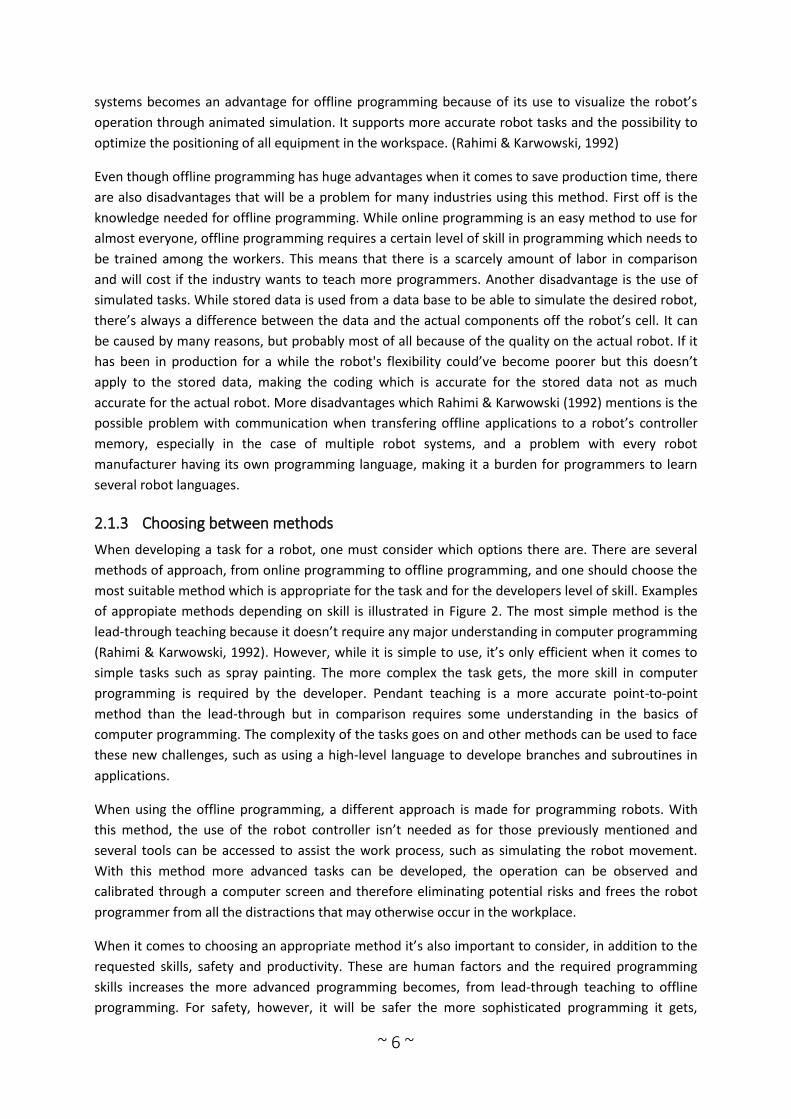
of appropiate methods depending on skill is illustrated in Figure 2. The most simple method is the
lead-through teaching because it doesn’t require any major understanding in computer programming
(Rahimi & Karwowski, 1992). However, while it is simple to use, it’s only efficient when it comes to
simple tasks such as spray painting. The more complex the task gets, the more skill in computer
programming is required by the developer. Pendant teaching is a more accurate point-to-point
method than the lead-through but in comparison requires some understanding in the basics of
computer programming. The complexity of the tasks goes on and other methods can be used to face
these new challenges, such as using a high-level language to develope branches and subroutines in
applications.
When using the offline programming, a different approach is made for programming robots. With
this method, the use of the robot controller isn’t needed as for those previously mentioned and
several tools can be accessed to assist the work process, such as simulating the robot movement.
With this method more advanced tasks can be developed, the operation can be observed and
calibrated through a computer screen and therefore eliminating potential risks and frees the robot
programmer from all the distractions that may otherwise occur in the workplace.
When it comes to choosing an appropriate method it’s also important to consider, in addition to the
requested skills, safety and productivity. These are human factors and the required programming
skills increases the more advanced programming becomes, from lead-through teaching to offline
programming. For safety, however, it will be safer the more sophisticated programming it gets,
~ 7 ~
where even offline programming has no interaction at all with the robot during the development.
What productivity means is the ratio of output units and input units. The input is the product of skill
and time (skill * time) of programming, while the output is the finished program or the number of
lines of code (LOC). There are more factors influencing but those mentioned above, (skills * time) and
LOC, are measurable units. (Rahimi & Karwowski, 1992)
Figure 2 Programming skill requirements. (Rahimi & Karwowski, 1992)
2.1.4 Human-Robot Collaboration
Both humans and robots capabilities and limitations differ from each other and to be aware of this
and study this more deeply can assist the work for more efficient production. It’s a field of study
which grows and deals with the possibility to interact human behaviour with the characteristics of
robotics and design more efficient robots and interactive human-robot workspaces (Rahimi &
Karwowski, 1992). Human-Robot Collaboration (HRC), also referred as Human-Robot interaction
(HRI), is about the way people can interact and communicate with robots and how robots can work
with people in the best way. It is believed by Dautenhahn and Saunders (2011) that HRI has an
economically impact as well as an impact in the daily life and the developing relationships with
machines. As HRI combines both human and robot factors in its research field, a wide knowledge is
required including psychology, cognitive science, social sciences, artificial intelligence, computer
science, robotics, engineering and human–computer interaction (Dautenhahn, et al., 2011).
2.1.4.1 Programming by Demonstration
A method that recur currently in human-robot interaction is PbD (Programming by Demonstration),
also known as imitation learning. The purpose of PbD is to allow an operator to program a robot by
simply performing a demonstration using their own movements to a sensor which then saves the
operator's actions to later implement them to the robot. Robot PbD has grown since early 1980s
(Billard & Calinon, 2008) as it turns out to potentially become an attractive method for simplifying
the programming of robots and reduce the time, and therefore the cost, of developing the robot
teaching and not to have it during production.
2.1.5 ABB robotics
ABB is a global leader in power and automation technologies. Based in Zurich, Switzerland, the
company employs 145,000 people and operates in around 100 countries. ABB consists of five
divisions, where each division are organized in relation to the customers and the business areas they
serve. They also invests in continued research and development and has seven research centers
around the world. It has resulted in many innovations and today, ABB is one of the largest suppliers
~ 8 ~
of engines and propulsion systems for industry, generators for wind power industry as well as power
grids worldwide.
In Sweden, ABB has approximately 9200 employees in 30 locations. Swedish ABB is a leading supplier
of products and systems for power transmission as well as process and industrial automation. Large
operating locations are in Västerås with about 4300 employees, Ludvika with around 2800
employees and Karlskrona with about 800 employees. With ABB Business Centers at ten locations in
Sweden, they offer better customer value by being locally present.
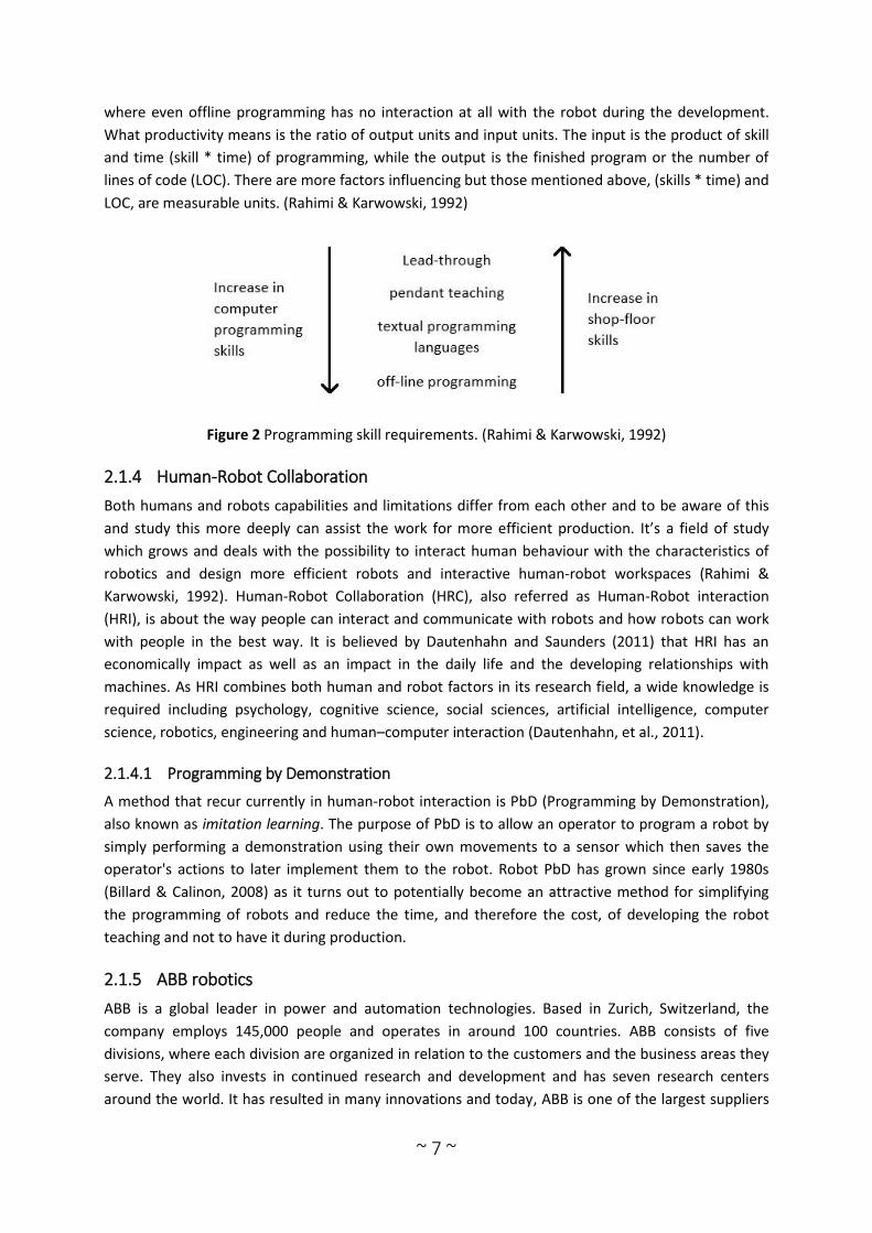
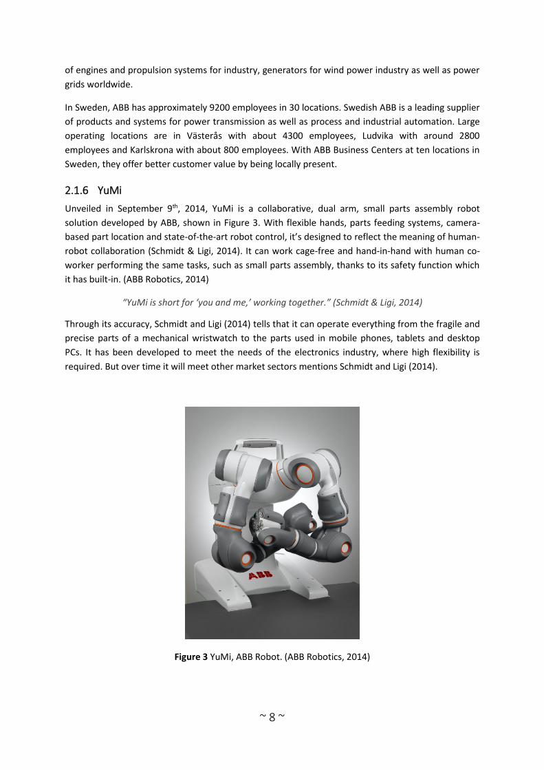
2.1.6 YuMi
Unveiled in September 9th, 2014, YuMi is a collaborative, dual arm, small parts assembly robot
solution developed by ABB, shown in Figure 3. With flexible hands, parts feeding systems, camera-
based part location and state-of-the-art robot control, it’s designed to reflect the meaning of human-
robot collaboration (Schmidt & Ligi, 2014). It can work cage-free and hand-in-hand with human co-
worker performing the same tasks, such as small parts assembly, thanks to its safety function which
it has built-in. (ABB Robotics, 2014)
“YuMi is short for ‘you and me,’ working together.” (Schmidt & Ligi, 2014)
Through its accuracy, Schmidt and Ligi (2014) tells that it can operate everything from the fragile and
precise parts of a mechanical wristwatch to the parts used in mobile phones, tablets and desktop
PCs. It has been developed to meet the needs of the electronics industry, where high flexibility is
required. But over time it will meet other market sectors mentions Schmidt and Ligi (2014).
Figure 3 YuMi, ABB Robot. (ABB Robotics, 2014)

~ 9 ~
2.1.7 Virtual reality
Virtual reality (VR), also referred as virtual presence, virtual environment or artificial reality
(Sheridan, 1992), is a computer-simulated environment which can be interacted by users in real time.
A user can communicate with the envrionment through sensory experiences including vision, sound,
touch, and even smell and taste (Nof, 1999). Many people today can recognize themselves in virtual
realities from computer and console games which are a good example of a virtual environment
where the user feels involved in the simulated world and can do things that otherwise would not
have been possible in the real world. In addition to games, VR is used for training simulations,
manufacturing, design tools and much more. In robotics VR can be used for designing robots,
programming complicated tasks and operate robots at far distance (also called teleoperation). An
example of a virtual reality used in robotics is RobotStudio, ABB's own software which is used to
program their own robots.
2.1.7.1 RobotStudio
RobotStudio is a VR software for the user to perform offline programming and simulation in their
own PC. It allows the user to develop their skills, programming and optimization without disturbing
production, which has several advantages that are mentioned in 2.1.2, Offline programming.
RobotStudio is additionally built on the ABB Virtual Controller, which allows the software to
implement realistic simulations using real robot programs and configuration files used in the work
place. (ABB Robotics)
2.2 Sensors
Jazar (2010) define sensors as components which detect and collect information about internal and
environmental states. Sensors are a dominant tool and today also important for modern industry. It
is used continuously in highly developed industrial processes and even for simple consumer
products. In production, for example, advanced sensors can be used to monitor and control the
manufacturing process (CNST, et al., 1995).
Sensor technology is a technology with great potential in many technical systems, where it can
improve its processes and create better reliability as well as serviceability. In 1860, Wilhelm von
Siemens developed a temperature sensor based on a copper resistor after a variety of materials were
examined in the early 1800s on how sensitive materials electrical resistance was against temperature
changes. This shows that the sensor technology requires itself materials science and engineering to
be developed. (CNST, et al., 1995).
If you look deeper into the anatomy of sensors, they consist generally of three basic components: a
sensor element, sensor packaging and connections, the is also a sensor signal processing hardware
(for some sensors there are additional components). An overview of a sensor system can be seen in
Figure 4.

~ 10 ~
Figure 4 Anatomy of a sensor system. (CNST, et al., 1995: 15)
2.2.1 Sensors in robotics
“Without sensors, a robot is just a machine, capable only of moving through a
predetermined sequence of action. With sensors, robots can react and respond to
changes in their environment in ways that can appear intelligent or life-like.”
(Martin, 2001)
To utilize the properties of sensors in industrial robotics was not recognized until the 1990s.
Previously, only taught joint positions combined with interlocks and time signals was used as
feedback for the robot (Nof, 1999). This was due to the idea of strictly controlled robots with known
positions of all objects in its workspace. It was later that sensors played a larger role in industrial
robotics, when safety and new practical solutions became recognized. There were two aims with the
sensors in the beginning, namely to create security and to increase the robot's capabilities by
allowing it to "see" the orientation of an object. Accidents caused by robots are rare but do yet
happen and the results have led to either property damage, worker injury or both. With no control
and prevention systems, accidents could easily occur if people were to intrude the robot’s workplace
unprepared. With the second aim of “seeing” the orientation, robots could be utilized even further
through and let the robot be able to detect defects on the material being handled and even detect
intruding workers and stop its activities (Nof 1999). Sensors play a large role when in control and
with the use of control units, a built-in sensor can send information about each link and joint of its
robot to the control unit which in return decides the robot configuration (Jazar, 2010).
In modern robotics, there are 7 types of sensors that is normally used for industrial robots: 2D vision,
3D vision, Force torque sensor, Collision detection sensor, Safety sensors, Part detection sensors and
other (such as tactile sensors). 2D vision sensors have long existed in the market and has several
functions, from motion detection to localization of parts on a pallet. 3D Vision is also widely used in
various functions and marks the objects in 3D using either two cameras at different angles or by a
laser scanner. 3D Vision is used in bin picking where it detects the object, recreates it in 3D, analyzes
it, and calls for the robot how to pick it up. Force torque sensors (FT sensor) monitors the forces
applied on the robot and can usually be found between the robot and its mounted tools. Applications

~ 11 ~
that use this type of sensor can be from assembly to lead-through programming where the FT sensor
monitors the movements that the operator teaches it. Collision detection sensors can be in different
shapes and may often be embedded in robots. These sensors can for example detect if pressure
occurs on a soft surface and and be able to signal the robot to limit or stop its movement, therefore,
being an fitting application for safe working environment and for collaborative robots. Safety sensors
can either be from cameras to lasers and is designed to notify the robot if there’s a presence within
its working space and then be able to act according to the situation, slowing down the pace as long
as the hindrance is within its working range or stop when the distance becomes too close. Part
detection sensors works in the same purpose as vision systems, detecting parts which should be
picked up, but rather gives feedback on the gripper position. This system can for example detect if
there was an error when picking up a part in its grasping task and repeats the task until the part is
well grasped. Other sensor systems can be used in robotics, such as tactile sensors which detect and
feel what’s in it, and thanks to the variation there’s usually a sensor for each specific task. (Bouchard,
2014)
2.2.2 Project sensor, Kinect
The Microsoft Kinect is a low-cost, RGB-D sensor with several useful features, such as high-resolution
depth and visual (RGB) sensing. Because of the broad information the sensor can provide in both
depth and visual, it opens new ways to solve the fundamental problems in computer vision and is
therefore widely used.
Kinect was originally an accessory for the Xbox console, created by Microsoft (Han, Shao, Xu, &
Shotton, 2013). It allowed players to interact with games without having to use a controller, this was
made possible with the sensor's 3-D motion capture algorithm of the human body. However, its
potential wasn’t only settled for games as the Kinect's depth sensing technology, along with its low
cost compared to other 3-D cameras, can provide solutions to many other computer vision problems.
The Kinect sensor with its depth sensing technology has a built-in color camera, infrared (IR)
transmitter and a microphone array. The depth sensor is obtained by a combination of the infrared
camera and projector, where the IR projector throws out a dot pattern on the environment which is
then captured by the infrared camera.
2.2.2.1 Body Tracking
A certain function the Kinect has is the Body Tracking. It is the process of positioning the skeleton
joints on a human body which allows the Kinect to recognize people, and be able to follow their
actions. It is established with depth image data and can track as many as six people and 25 skeletal
joints from each individual, this includes the user’s head, hands, centre of mass and more. Each
skeleton point is also provided with an X, Y and Z values, these helps to set the orientation of the
joints. The orientations of the bones are brought in two forms:
A hierarchical rotation based on a bone relationship defined on the skeleton joint structure
An absolute orientation in Kinect camera coordinates
The data from the orientation is given out in form of quaternions and rotation matrices so it can be
used in different animation scenarios.
~ 12 ~
Using the skeletal tracking system to obtain the joints, a hierarchy of bones are defined and specified
as parent and child. With the Hip Centre as the root and parent, the hierarchy reaches to all
endpoints on the body: feet, head and hand tips. In a child joint, the bone rotation is also stored and
it’s relative to its parent. This is called hierarchical rotation and tells much rotation in 3D space is
needed to obtain the direction of the child bone from the parent.
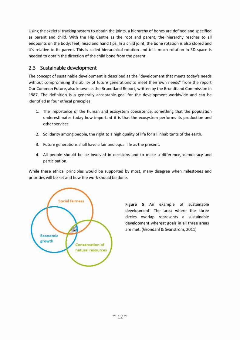
2.3 Sustainable development
The concept of sustainable development is described as the "development that meets today's needs
without compromising the ability of future generations to meet their own needs" from the report
Our Common Future, also known as the Brundtland Report, written by the Brundtland Commission in
1987. The definition is a generally acceptable goal for the development worldwide and can be
identified in four ethical principles:
1. The importance of the human and ecosystem coexistence, something that the population
underestimates today how important it is that the ecosystem performs its production and
other services.
2. Solidarity among people, the right to a high quality of life for all inhabitants of the earth.
3. Future generations shall have a fair and equal life as the present.
4. All people should be be involved in decisions and to make a difference, democracy and
participation.
While these ethical principles would be supported by most, many disagree when milestones and
priorities will be set and how the work should be done.
Figure 5 An example of sustainable
development. The area where the three
circles overlap represents a sustainable
development whereat goals in all three areas
are met. (Gröndahl & Svanström, 2011)

~ 13 ~
3 Frame of reference
This chapter presents a comprehensive literature review of existing human-robot collaboration
applications in publications. Later, the chapter justifies the usefulness of integrating online
programming methods with virtual environments.
3.1 Programming virtual robot by demonstration
Here, the focus lies on studies in which different authors have used different methods to control a
robot's path and configuration. This includes Ge’s (2013) study whose main focus was to control the
robot's movement through a PbD (Programming by Demonstration) method based on an optical
tracking system. He investigated the possibility to reduce both the learning difficulty of robot
programming and the time it takes to program for upcoming challenges in 3C industries. With the
PbD method and optical tracking system, the robot could imitate operator arm and hand motions in
6D (translation and rotation). The result of this study showed that the robot could follow a human’s
arm and hand motions accurately with a small but acceptable time delay for some applications. Ge’s
experiment may be the nearest similar work to our project focus, however, his focus lies in
programming the physical robot, not a virtual one, and uses a different vision system than what will
be used in this project. With this in mind, a search for additional papers from conferences and
articles focusing on PbD, Optical Tracking System, Kinect or VR (Virtual Reality) was made. From
these focus areas, publications were selected from the 2000s which could assist with the theory of
applying PbD for virtual robots. After the papers were reviewed, they were sorted into three sub-
headings: PbD applications, Sensors applied in HRC and Other application toward HRC. PbD
applications include Online Programming (OLP), Offline Programming (OFP), Programming by
Demonstration (PbD), Virtual Reality (VR), etc. Sensors applied in HRC include Human-Robot
Collaboration (HRC), Augmented Reality (AR), Sensor systems, etc. Other application toward HRC
presents an article which doesn’t focus on programming a robot nor PbD but does include VR, HRC
and the use of a Kinect device.
3.1.1 PbD applications
Recent progress of programming methods has mostly been to simplify the programming process,
making the process take less time, have less need for experienced robot programmers and safer.
Except of traditional ways such as lead-through, pendant teaching and OFP, other methods are now
making progress towards HRC, such as Programming by Demonstration. This section presents a
number of papers that use a PbD method for programming robots, both physical and virtual. The
author Makris et al. (2014) presents a PbD method for dual arm robot programming where the
proposed robotic library aimed for humanlike capabilities, and implemented bi-manual procedures.
Dual arm robots has been an interesting topic for industries for decades because of their developing
capabilities in dexterity, flexibility and more, but the programming is complex and therefore there’s a
need for a software which simplifies the robot programming procedure. Their method was
implemented in an assembly and the result showed that the user could easily interact with a dual
arm robot by the use of depth sensors, microphones and GUIs (Graphical user interface). They
identified that the complexity in the programming could be reduced, non-experienced users can use
it and the information from the robot could easily be managed into the database system. In (Aleotti
et al., 2003), the authors present a PbD system which is able to operate assemblies in a 3D block
environment. The problem they faced was about the need for a simpler programming technique that

~ 14 ~
allows operators with little or no robot programming experience to implement new tasks to a robot.
The system was based on a virtual reality teaching interface, using a data glove with a 3D tracker
which an operator wearing it uses it to demonstrate the intended tasks. When performing a
sequence of actions, the system recognize, translates, performs the task in a simulated environment
and finally gets validated. It resulted in a prototype of a PbD system that uses a data glove as an
input device, giving the human-robot interaction a natural feeling.
3.1.2 Sensors applied in HRC
This section presents publications in which authors have used sensor technology to create a better
human-robot collaboration environment. For instance, Wang et al. (2013) present a real-time active
collision avoidance method in an augmented environment, where humans and robots work together
in a collaborative environment. A challenge is to avoid possible collisions for the safety of the human
operator. The authors deal with this challenge by using virtual 3D models of robots and real camera
images of operators to monitor and detect possible collisions. The 3D models represented a
structured shop-floor environment and by linking two Kinect sensors, they could mimic the
behaviour of the real environment. By connecting virtual robots and human operators to a set of
motion and vision sensors, they could link the robot control with collision detection in real-time and
thus came with a solution which enabled different strategies of collision-avoidance. Another way to
use sensors for collaboration between man and robot is presented in C. L. Ng’s (2010) work where he
fused information from a camera and a laser range finder to teach a robot in an AR (Augmented
Reality) environment, and then tested the method in a robot welding application. The problem posed
is about the SME (small and medium enterprise) manufacturing where a large variety of work pieces
requires experienced robot programmers to often have to reprogram an automated robotic system,
which is both uneconomical and inefficient in the long term. The author is therefore looking for a
quick and easy method to program robots. An HRI system was developed whose function was to
provide visual information from video images to the operator to use the system and capture the
Cartesian information on the operator's intended robot working paths through a laser rangefinder.
The study achieved a system which teaches the robot path through a simple point-and-click
algorithm and the tool settings can be modified through interaction with a virtual tool in an AR
environment.
3.1.3 Other application towards HRC
Matsas and Vosniakos (2015) present a Virtual Reality Training System (VRTS) which creates an
interactive and immersive simulation for the operator to work in a Human-Robot Collaboration (HRC)
environment where simple production tasks are carried out. Due to the pursuit of better quality and
productivity of manufacturers, the requirement for a human-robot collaboration environment has
arisen and the authors carry out a study in which this system shall be designed and tested so that in
the long term could become a platform for programming HRC manufacturing cells. A virtual world
including a shop floor environment with equipment was designed together with a training scenario
which was a simple tape-laying for composite parts case performed in a HRC environment. To allow
the user to feel enveloped by the virtual workplace and be able to interact in it, the authors use a
Kinect sensor and HMD (Virtual Research Head Mounted Display), where the HMD is used both to
envelop the user to the environment and as an input device for the Kinect sensor head tracking. The
study showed positive results and the authors suggested that such an application can come to good
use for training and testing in a HRC environment.
~ 15 ~
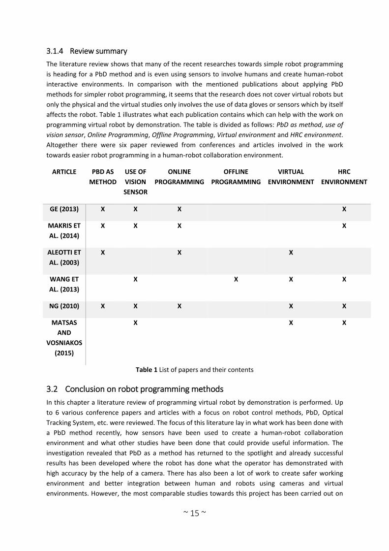
3.1.4 Review summary
The literature review shows that many of the recent researches towards simple robot programming
is heading for a PbD method and is even using sensors to involve humans and create human-robot
interactive environments. In comparison with the mentioned publications about applying PbD
methods for simpler robot programming, it seems that the research does not cover virtual robots but
only the physical and the virtual studies only involves the use of data gloves or sensors which by itself
affects the robot. Table 1 illustrates what each publication contains which can help with the work on
programming virtual robot by demonstration. The table is divided as follows: PbD as method, use of
vision sensor, Online Programming, Offline Programming, Virtual environment and HRC environment.
Altogether there were six paper reviewed from conferences and articles involved in the work
towards easier robot programming in a human-robot collaboration environment.
ARTICLE PBD AS
METHOD
USE OF
VISION
SENSOR
ONLINE
PROGRAMMING
OFFLINE
PROGRAMMING
VIRTUAL
ENVIRONMENT
HRC
ENVIRONMENT
GE (2013) X X X X
MAKRIS ET
AL. (2014)
X X X X
ALEOTTI ET
AL. (2003)
X X X
WANG ET
AL. (2013)
X X X X
NG (2010) X X X X X
MATSAS
AND
VOSNIAKOS
(2015)
X X X
Table 1 List of papers and their contents
3.2 Conclusion on robot programming methods
In this chapter a literature review of programming virtual robot by demonstration is performed. Up
to 6 various conference papers and articles with a focus on robot control methods, PbD, Optical
Tracking System, etc. were reviewed. The focus of this literature lay in what work has been done with
a PbD method recently, how sensors have been used to create a human-robot collaboration
environment and what other studies have been done that could provide useful information. The
investigation revealed that PbD as a method has returned to the spotlight and already successful
results has been developed where the robot has done what the operator has demonstrated with
high accuracy by the help of a camera. There has also been a lot of work to create safer working
environment and better integration between human and robots using cameras and virtual
environments. However, the most comparable studies towards this project has been carried out on

~ 16 ~
physical robots and not on virtual ones. Therefore, a further study in PbD on virtual robots is needed.
The technology exists and if successful, it could simplify the work to program robots and fine-tune
the program in a virtual software. For the project, major focus will lie in making the integration
between the vision system and virtual program work and that the accuracy of the robot is as high as
possible.
4 Data acquisition and analysis of data
In this chapter the work process of acquiring the necessary data is described and how the data
obtained is interpreted.
4.1 Obtaining necessary material
At the beginning of the project all necessary software and hardware was first obtained and installed.
For the project a vision sensor was necessary as well as the chosen sensor’s software, software for
the virtual robot and an IDE (Integrated Development Environment). These were necessary for
making the code and the following hardware and software was chosen for this work:
Hardware: Kinect for Xbox One sensor and Kinect Adapter for Windows
Software: Visual Studio Professional 2013 with Update 4, RobotStudio 6.00 and Kinect for Windows
SDK 2.0
With the Kinect SDK, complete code samples could be downloaded and used to get a head start in
the programming and avoid making code that has already been done, like reinventing the wheel. A
fitting code sample for the project was picked and is described in chapter 4.2.
4.2 Acquisition of data
Figure 6 A ”lasso” hand gesture
What was of interest in the Kinect for the project was how the sensor presented the data for the
positioning of the body and its skeletal joints. That specific data would become necessary for the
project later on because it could be used to create gesture commands which would allow us to
control the virtual robot’s movement. To get the data, a base to work with had to be acquired. The
Kinect supports users who wants to create new software’s using the sensor and thus has finished
samples of code that can be worked on. In this case, the Body Basics-WPF that demonstrates how to
obtain and visualize body frames from the sensor was retrieved. Running the code while having the
sensor connected visualized what can be seen in Figure 7. It shows something like a stick figure which
represents your body and extends from your heads centre to your feet. Each hand has four joints
which are tracked and represents the wrist, hand centre, hand tip and thumb. Around each hand

~ 17 ~
there’s also a circle which change in colour, these represent the user’s hand gesture and change
colour if the user’s hand is either open, closed or in a “lasso” state (when the user has the forefinger
and middle finger open and the rest closed). A lasso state is visualized in Figure 6.
Figure 7 Kinect visualizing the body frame and its skeletal joints.
The finished sample just shows the body frame though and doesn’t print out any data. This was just a
sample and additional code had to be added in order to get the desired position data. An easy way to
receive position data from the sensor is by letting the sensor calculate the distance between the
user’s hands. This can be achieved by adding the following code in the Body Basics-WPF (C#):
Add the joints:
Joint pRH; Joint pLH;
Declare them as right and left hand inside “if (body.IsTracked)“:
pRH = body.Joints[JointType.HandRight]; pLH = body.Joints[JointType.HandLeft];
Make the calculation with absolute value:
double absDistanceX = Math.Abs(pRH.Position.X - pLH.Position.X); double absDistanceY = Math.Abs(pRH.Position.Y - pLH.Position.Y); double absDistanceZ = Math.Abs(pRH.Position.Z - pLH.Position.Z);
In this way, the distance may be used to instruct the robot where it should move to, with maybe the
left hand as a reference point for the robot's current position. However, when the project targets to
later be implemented for the two-armed ABB robot YuMi, both hands is going to be needed to
instruct the direction and distance to create a smooth application. Therefore, the code needs to be
~ 18 ~
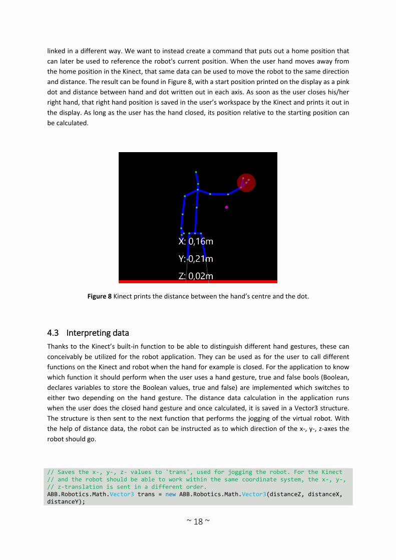
linked in a different way. We want to instead create a command that puts out a home position that
can later be used to reference the robot's current position. When the user hand moves away from
the home position in the Kinect, that same data can be used to move the robot to the same direction
and distance. The result can be found in Figure 8, with a start position printed on the display as a pink
dot and distance between hand and dot written out in each axis. As soon as the user closes his/her
right hand, that right hand position is saved in the user’s workspace by the Kinect and prints it out in
the display. As long as the user has the hand closed, its position relative to the starting position can
be calculated.
Figure 8 Kinect prints the distance between the hand’s centre and the dot.
4.3 Interpreting data
Thanks to the Kinect’s built-in function to be able to distinguish different hand gestures, these can
conceivably be utilized for the robot application. They can be used as for the user to call different
functions on the Kinect and robot when the hand for example is closed. For the application to know
which function it should perform when the user uses a hand gesture, true and false bools (Boolean,
declares variables to store the Boolean values, true and false) are implemented which switches to
either two depending on the hand gesture. The distance data calculation in the application runs
when the user does the closed hand gesture and once calculated, it is saved in a Vector3 structure.
The structure is then sent to the next function that performs the jogging of the virtual robot. With
the help of distance data, the robot can be instructed as to which direction of the x-, y-, z-axes the
robot should go.
// Saves the x-, y-, z- values to 'trans', used for jogging the robot. For the Kinect // and the robot should be able to work within the same coordinate system, the x-, y-, // z-translation is sent in a different order. ABB.Robotics.Math.Vector3 trans = new ABB.Robotics.Math.Vector3(distanceZ, distanceX, distanceY);

~ 19 ~
// Initiates the jogging procedure in Class1 and sends with it calculated data MyKinectData.JogRobot(trans);
5 Development of communication software
In this chapter the creation of the communication software is described, how the procedure went,
what methods were used and how the final product or prototype became.
5.1 Method on approach
A desired sample code has been taken from the finished library, been modified and now saves the
data as distance data in the x-, y- and z-axis, described in Chapter 4. With the help of this data should
now an add-in for ABB's software RobotStudio be created that allows users control the robot through
their hand movements and gestures and create paths. Before the two-armed robot YuMi can be
taken care of, it’s a good idea to get the basis for the program to work first, in which a one-armed
robot is more suited to start with. Thus the objectives became more clear for which functions must
be implemented first instead of directly working on the whole of the project from day one. A detailed
design of the application was first done in order to understand how it should process. Should the
virtual replicate the user’s arm movement, in several joints? Or should the user be able to “grab” the
robot through virtual hands created in the virtual environment in RobotStudio and guide its path? All
suggestions were considered possible but one approach for the project was chosen eventually that
involved the manipulation of the robot's TCP. By a hand gesture the robot can be jogged in the
direction desired by the user, a method easily understandable. This coexists well with the method for
getting the Kinect data as well where the distance is compared to a fixed point and the user's hand,
which in the robot world can be a comparison between the distance of the robot's current TCP and a
new designated TCP. A flowchart has been created to illustrate the structure of the program and is
shown in Figure 9. To start the add-in for RobotStudio, two buttons is going to be created in a new
tab in the software. One button shall activate the Kinect for further instructions to the robot, the
other button shall create a path of the existing targets which will be created with the help of the
sensor. Once the Kinect activates, it will display a new window which will show the body frame of the
user (described in Chapter 4.2). It will keep track of if the user decides to close the window, and if so
the sensor will stop. While active, the sensor will track its user and check if the user makes any hand
gestures. If the user closes his/her hand, the current position of the hand as well as the robot TCP will
be saved. Once saved the user will grab control of the robot and it will jog in the same direction as
the user’s hand moves. If instead the user uses the lasso gesture, the application will save the current
position of the robot’s TCP with orientation as a target.

~ 20 ~
Figure 9 Flowchart
5.2 Challenges
As sensory technology as well as PC SDK for RobotStudio were two new areas that hasn’t been
studied before the bachelor programme, several challenges were faced to complete this task. The
first and foremost was to get a wider understanding of how the programming goes to the Kinect
sensor and PC SDK in C#. As they have their own API’s (application programming interface), which
provide with complete specifications that allow the user to more easily use and communicate with
specific software, they needed to be checked through and studied to be sure what API's need to be
used for this project. To get started, help and inspiration was received from teachers, tutors, other
individuals, forums, guides with examples and previous works aimed towards something that my
project contains (e.g. other Kinect applications). Examples would be the MSDN forums and ABB’s
Robotics Developer Center which provided with answers for questions and walkthroughs of how to
implement a specific function in applications. As attempts were made, some functions had to be
remade or the class itself scraped and start over. One of those attempts were a sample that was
further worked on which when activated created a new window in RobotStudio and showed an
online monitor of a virtual robot. The problem with this application though was that it caused more
work than needed and complications to achieve the desired application and was therefore scraped
and a new class had to be created and start over. This was due to lack of understanding the new
API’s and no clear view on how the addition would be developed, a vision existed but the method to
get there did not. But as function or even classes were scraped, lessons were learned and several
lines of code could still become useful and reused in a new class.
~ 21 ~
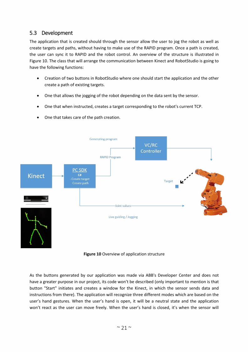
5.3 Development
The application that is created should through the sensor allow the user to jog the robot as well as
create targets and paths, without having to make use of the RAPID program. Once a path is created,
the user can sync it to RAPID and the robot control. An overview of the structure is illustrated in
Figure 10. The class that will arrange the communication between Kinect and RobotStudio is going to
have the following functions:
Creation of two buttons in RobotStudio where one should start the application and the other
create a path of existing targets.
One that allows the jogging of the robot depending on the data sent by the sensor.
One that when instructed, creates a target corresponding to the robot's current TCP.
One that takes care of the path creation.
Figure 10 Overview of application structure
As the buttons generated by our application was made via ABB's Developer Center and does not
have a greater purpose in our project, its code won’t be described (only important to mention is that
button "Start" initiates and creates a window for the Kinect, in which the sensor sends data and
instructions from there). The application will recognize three different modes which are based on the
user’s hand gestures. When the user’s hand is open, it will be a neutral state and the application
won’t react as the user can move freely. When the user’s hand is closed, it’s when the sensor will

~ 22 ~
initiate the jogging of the robot and with it sending the calculated data mentioned in chapter 4. And
lastly when the user does the lasso gesture, the application will save the current TCP as a new target.
5.3.1 Jogging robot
As earlier shown, the following line of code was written in the Kinect class and is active while the
user’s hand is closed:
MyKinectData.JogRobot(trans);
This initiates the jogging function for the virtual robot in the new class named Class1. With its
initiation the distance data from the sensor is implemented. To see that the communication works
and can initiate some kind of movement of the robot before further work on the manipulation, a
while loop was written that instructs the robot to go to a predefined position when the user closes
his/her hand. To make this work the active station and its mechanism had to be defined first. Then
the current TCP of the robot will be defined by giving the Matrix4 structures named currentTCP and
newTCP a joint orientation and translation value taken from the active station’s tool frame, namely
global matrix.
Matrix4 newTCP = stn.ActiveTask.ActiveTool.Frame.GlobalMatrix;
With those stated, the “while” function may be declared and the translation of the position of the
robot is carried out. The following code performs the mentioned function:
public void JogRobot(ABB.Robotics.Math.Vector3 trans) { Station stn = Station.ActiveStation; Mechanism mech = stn.FindGraphicComponentsByType(typeof(Mechanism))[0] as Mechanism; Matrix4 currentTCP = stn.ActiveTask.ActiveTool.Frame.GlobalMatrix; int i = 0; while (i++ < 1000) { Matrix4 newTCP = stn.ActiveTask.ActiveTool.Frame.GlobalMatrix; newTCP.Translate(0.001, 0, 0); double[] jv; if (mech.CalculateInverseKinematics(newTCP, Matrix4.Identity, false, out jv)) { mech.SetJointValuesAsync(jv, false).PumpingWait(); Station.UpdateGraphics(true); } } }
As can be seen in the code the Vector3 trans is now not used when only predefined numbers are
running. The next step is to implement the data from trans and manipulate the virtual robot’s
movement through it. The while was removed but its content kept and instead of having the
translation of newTCP to go with specific numbers, the following code was used:

~ 23 ~
newTCP.Translate(trans.x / 50, trans.y / 50, trans.z / 50);
This transfers the values sent by the sensor instead and uses it as the translation of the robot’s
movement. The translation receives each axis value earlier given to trans. To ensure that the robot
won’t be too sensitive towards the sensor’s sent signals and cause loss of control to the robot, the
trans value is divided before it’s implemented with a value depending on how the user wants the
sensitivity. As the input of translation values has changed, the mech.SetJointValues inside the if
function could be changed to the following way:
mech.SetJointValues(jv, false);
The following lines of code became the result:
public void JogRightRobot(ABB.Robotics.Math.Vector3 transR) { Station stn = Station.ActiveStation; Mechanism mech = stn.FindGraphicComponentsByType(typeof(Mechanism))[0] as Mechanism; Matrix4 newTCP = stn.ActiveTask.ActiveTool.Frame.GlobalMatrix; newTCP.Translate(transR.x / 50, transR.y / 50, transR.z / 50); double[] jv; if (mech.CalculateInverseKinematics(newTCP, Matrix4.Identity, false, out jv)) { mech.SetJointValues(jv, false); Station.UpdateGraphics(true); } }
The resulting code is only compatible to one-armed robots. For the two-armed YuMi robot to be able
to use the application the lines of code had to be changed and is described later in chapter 6.2.
5.3.2 Creating Targets
For the creation of the target, it’s initiated when the user does the lasso gesture. As guidance, a
sample was followed from RobotStudio Development named Creating Target. A big difference,
however, was that the function that defines the positions of the targets need to retrieve the position
of the robot's current TCP, instead of sending predetermined positions in x-, y-, z-axis. To achieve this
the robot can retrieve data in the same way as the code for jogging, getting the robot’s current TCP
and instead of sending a Vector3 value to ShowTarget the following could be used:
ShowTarget(new Matrix4(currentTCP.Translation, currentTCP.EulerZYX));
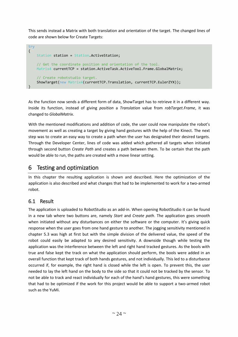
~ 24 ~
This sends instead a Matrix with both translation and orientation of the target. The changed lines of
code are shown below for Create Targets:
try { Station station = Station.ActiveStation; // Get the coordinate position and orientation of the tool. Matrix4 currentTCP = station.ActiveTask.ActiveTool.Frame.GlobalMatrix; // Create robotstudio target. ShowTarget(new Matrix4(currentTCP.Translation, currentTCP.EulerZYX)); }
As the function now sends a different form of data, ShowTarget has to retrieve it in a different way.
Inside its function, instead of giving position a Translation value from robTarget.Frame, it was
changed to GlobalMatrix.
With the mentioned modifications and addition of code, the user could now manipulate the robot’s
movement as well as creating a target by giving hand gestures with the help of the Kinect. The next
step was to create an easy way to create a path when the user has designated their desired targets.
Through the Developer Center, lines of code was added which gathered all targets when initiated
through second button Create Path and creates a path between them. To be certain that the path
would be able to run, the paths are created with a move linear setting.
6 Testing and optimization
In this chapter the resulting application is shown and described. Here the optimization of the
application is also described and what changes that had to be implemented to work for a two-armed
robot.
6.1 Result
The application is uploaded to RobotStudio as an add-in. When opening RobotStudio it can be found
in a new tab where two buttons are, namely Start and Create path. The application goes smooth
when initiated without any disturbances on either the software or the computer. It’s giving quick
response when the user goes from one hand gesture to another. The jogging sensitivity mentioned in
chapter 5.3 was high at first but with the simple division of the delivered value, the speed of the
robot could easily be adapted to any desired sensitivity. A downside though while testing the
application was the interference between the left and right hand tracked gestures. As the bools with
true and false kept the track on what the application should perform, the bools were added in an
overall function that kept track of both hands gestures, and not individually. This led to a disturbance
occurred if, for example, the right hand is closed while the left is open. To prevent this, the user
needed to lay the left hand on the body to the side so that it could not be tracked by the sensor. To
not be able to track and react individually for each of the hand’s hand gestures, this were something
that had to be optimized if the work for this project would be able to support a two-armed robot
such as the YuMi.

~ 25 ~
6.2 From one- to two-armed robot
First and foremost, the code had to be optimized to let the application act separately for each hand’s
hand gestures when running the Kinect. This could be achieved with the following:
switch (body.HandRightState) { case HandState.Open:
Instead of:
switch (handState) { case HandState.Open:
With the hands individually tracked, they can handle true and false values separately, and act
according to instructions. But as they are separated, all the functions needed to be implemented for
both left and right hand function. This leads to that the coding gets double rows of the same code
with only the names different from each other, this may not be optimal, but was a simple solution
that is easy to understand and follow. Examples is shown below with two functions that are the same
but with different names, result of working with right and left hand individually:
Example 1: // Switch for controlling robot with right hand public bool moveSwitchR { get; set; } // Switch for controlling robot with left hand public bool moveSwitchL { get; set; } Example 2: // Calculating distance between first home position and right hand position in x-axis (right hand) double calcDistanceXR = homeR.Position.X - pRH.Position.X; // Calculating distance between second home position and left hand position in x-axis (left hand) double calcDistanceXL = (homeL.Position.X - pLH.Position.X);
As when both translation data from right and left arm is calculated, the data is sent just as before to
the jogging function in Class1. But just as with the code lines for the Kinect, the jogging needs two
separate initiations for each hand. This is necessary for the application to act independently for each
hand.
Right hand: // translation data of the right hand, calculated by the Kinect ABB.Robotics.Math.Vector3 transR = new ABB.Robotics.Math.Vector3(distanceZR, distanceXR, distanceYR); // Initiates the jogging procedure for the right arm in Class1 MyKinectData.JogRightRobot(transR);

~ 26 ~
Left hand: // translation data of the left hand, calculated by the Kinect ABB.Robotics.Math.Vector3 transL = new ABB.Robotics.Math.Vector3(distanceZL, distanceXL, distanceYL); // Initiates the jogging procedure for the left arm in Class1 MyKinectData.JogLeftRobot(transL);
As for the lines of code in the jogging function, most of the changes were made there for the
adaptation of the YuMi. First, each robot had to be identified by name and retrieved. Because it’s no
longer a single robot, a search for the mechanism of the active station would not work. Then, as
before, the current TCP will be defined, but just the right arm’s TCP in the jogging function for the
right arm and the left arm’s TCP in left arm function.
Right hand: Matrix4 rightYuMiCurrentTCP = rightYuMi.Task.ActiveTool.Frame.GlobalMatrix; rightYuMiCurrentTCP.Translate(transR.x / 50, transR.y / 50, transR.z / 50); Left hand: Matrix4 leftYuMiCurrentTCP = leftYuMi.Task.ActiveTool.Frame.GlobalMatrix; leftYuMiCurrentTCP.Translate(transL.x / 50, transL.y / 50, transL.z / 50);
To enable a multi-axis robot such as YuMi to perform the function, lines of code needed to be added
to retrieve arm plane information, including arm angle and arm length. These will all in the end of the
function be used when the joint values are set. The finished adjusted code for the YuMi robot, one-
armed robots and an illustration showing how the application works can be found in the following
appendices: Appendix A - Illustration of how the add-in works, Appendix B - Complete code applied
for one-armed robot and Appendix C - Complete code applied for dual armed YuMi robot.
7 Discussion and other improvement measures
In this chapter an assembled discussion of the work is presented, as well as suggestions for further
research and improvements.
7.1 Discussion
The resulting application shows a new method for simple programming in a virtual environment that
combines the best of two worlds; the simplicity of online programming together with the flexibility of
offline programming. The project's goal was to develop an approach for lead-through programming
in a virtual environment, through the use of a user's hands. The expected result would be a
prototype of a hand gesture programming application for virtual environments that generates
instructions for a robot, which should also be able to be implemented with ABB's new collaborative
robot: YuMi. With the chosen method which was carried out during development, an application was
successfully developed that could live up to those expectations. With a Kinect sensor the application
allows a user to use their hands to demonstrate and manipulate the robot’s motions in RobotStudio's
virtual environment. Through hand gestures, users can decide when they wish to jog the robot and
~ 27 ~
when targets for the robot’s path should be generated. It works for one-armed industrial robots as
well as two-armed such as ABB's YuMi.
During the development several occasions arose which caused obstacles to the flow of the work
process. As a newcomer to the project’s many topics as sensors and PC SDK, there were several
misunderstandings and better understanding was necessary before you could get started, this did so
the work flow slowed often down. This was difficult as well as what is also difficult for many other
programmers; to create a functional code which when it happens, must find and fix certain lines of
code which seems correct but isn’t. Something that was too complicated to get developed and
implemented in the final prototype was the robot's orientation during the jogging phase, which is the
application's main bottleneck. This causes the program to have less flexibility for the user to program
a robot when the prototype can currently only jog the robot in the TCP axis without being able to
rotate any of them towards a new direction. The reason for this is that no practical method could be
developed in time, but only attempts that didn’t work well enough to be implemented. For example,
the orientation could be too sensitive and the robot TCP could end up in unwanted directions when
the user only rotates a little with the using hand.
In the following subchapters, possible improvement is presented that were identified during the
work which are not included in this project:
7.1.1 Implement orientation
As mentioned, a well-balanced orientation methodology is needed for the application to become
more flexible for the user in order to jog the virtual robot. Different methods can be looked into to
see if there’s any useful ways that can be implemented. Is there one? This brings up the question of
how useful a vision sensor can become in the work towards finding new methods for more efficient
programming of robots.
7.1.2 Absolute control
As the application currently operates the user is technically only instructing in which direction the x-,
y- and z-axis the robot should jog towards, without stopping in the same distance as the user is
currently holding their hand. This can be compared with a teach pendant in which the hand is the
lever that controls the jogging of the robot. To be able to have absolute control where the robot
replicates the user's exact movements, the lines of code for jogging needs to be overlooked, see
what needs to be added, modified and/or deleted in that section. If successful, the next step would
be to achieve control of each joint of robot by linking each joint of the human arm.
7.1.3 Immersive environment
For the goal to program the robot by demonstration and achieve absolute control, a possible
continued work in this project is to immerse the user in the virtual world. Through immersive devices
such as Oculus Rift, the user could see into the robot's virtual environment and through the robot’s
"eyes". In this way the user could perform the desired path and teach the robot in a more
collaborative approach.

~ 28 ~
7.1.4 Sensor optimization
One Kinect sensor was far enough to develop a functional application for RobotStudio, but not
optimal. Further work could be done where additional sensors were added to observe the user from
different angles and achieve more precise manipulation of the robot movement through the users
own movement. Not just vision sensors, other types of sensors could also be added to optimize the
application’s performance, such as force sensors and sound sensors. With force sensors the user
could possibly be able to manipulate a robot’s gripper and with how much force it should open and
close. By using a sound sensor, which the Kinect v2 in fact has, further work could be done where the
user doesn’t only send instructions to RobotStudio and the virtual robot through hand gestures but
also with voice commands.
7.1.5 Programming by Observation
All projects have their goals and further work, but there’s usually also a final destination where a first
prototype is the first step towards it. Programming by Observation, or PbO, is a supposed method in
which by observing their human user, the machine can create a complete program that is a
replication of the same performed task that the user recently did. It’s a different approach in
comparison with the first prototype in which PbO is intended to make more of a recording that
creates a program after the user has performed their task, while the prototype generates a path
while the user controls it. But the first prototype still supports the work towards a possible PbO
application later on and further studies can be carried out in an attempt to create such a program.
8 Conclusions
The conclusions from this project objectives are presented in this final chapter along with the
author's private words.
8.1 Conclusions on completion of goals
A new approach towards lead-through programming was going to be developed and a prototype of
such application presented in the end of the project. First, necessary material was acquired and
literature about topics related to the project were sought together with earlier related work. Then
the practical work began where the application for the project was created. First the Kinect sensor
was organized with extra code to visualize and calculate distance data which is later sent for
translation and become instructions for the virtual robot. For the robot part a new section in Robot
Studio was first developed with buttons for the user to be able to initiate the application. After a new
section was created the jogging function were coded which would jog the robot depending on the
received data. Lastly a function was made which generates the targets in the robot's current tool
position and a complete feature that allows the user to create a path between all targets through a
simple push of a button. The result became an add-in that when initiated, opens a new way of easy
lead-through programming on a virtual robot. It’s easy to learn as no previous computer knowledge
is required in order to quickly learn how this application works. It utilizes the functionality of the
Kinect through three simple hand gestures to jog and create targets to the robot. Goals which
complies with the milestones which University of Skövde and ABB have set were reached and are
clarified in the specified list below:

~ 29 ~
Develop a prototype application using a robot lead-through programming method for virtual
environments.
Through either motions, demonstration and/or grasping allow the user to teach the virtual
robot desired tasks by moving it to different positions.
Should be capable of generating robot tasks which followed the movement of the user’s
hands.
A suitable vision sensor and RobotStudio should be used.
To support further development of human-robot collaboration, the user should be able to
use the developed prototype for the new two-armed ABB robot called YuMi.
8.2 The author's final words
It has been a bumpy road with many obstacles but as a whole, work has gone well. Much time has
been spent in this project, but I’m still feeling that more could have been added if I had been more
assertive with time to spend as it often became stressful. Regardless the workflow has been in a
good pace where everything was in accordance with both the university and the company's views.
The priorities were very specific from week to week, where one thing at a time was taken care of,
personally an appropriate method. When the report was in focus there were initially a slow start but
when relevant literature was found, the work pace could quickly catch up. The project fulfilled many
of my expectations and I was able to work wholeheartedly with the things that interest me the most
for a company that I have great respect for. Moreover, thanks to the school and the company, I was
aided by tutors, teachers and other who gave their fullest support when any obstacles appeared. This
allowed me to develop a qualitative result. With their support, it was like I never worked alone but
rather in a collaborative group of dedicated people. The project has shown me how one's dedication
can and will create a collaborative community between people and robots in the future.
~ 30 ~
List of references
ABB Robotics. (2014). YuMi - Creating an automated future together. You and me..
http://new.abb.com/products/robotics/yumi [2015-02-05].
ABB Robotics. (u.d). RobotStudio. http://new.abb.com/products/robotics/robotstudio [2015-03-16].
Aleotti, J., Caselli, S. & Reggiani, M. (2003). Toward Programming of Assembly Tasks by
Demonstration in Virtual Environments. In Proc. Int. Workshop Robot and Human Interactive
Commun. Millbrae, CA Oct. 31-Nov. 2 2003, pp. 309-314.
Billard, A., Calinon, S., Dillmann, R. & Schaal, S. (2008). Robot Programming by Demonstration. In
Springer handbook of robotics. Springer Berlin, Heidelberg, pp. 1371-1394.
Bouchard, S. (2014). 7 Types of Industrial Robot Sensors. http://blog.robotiq.com/bid/72633/7-
Types-of-Industrial-Robot-Sensors [2015-03-17].
Dautenhahn, K., & Saunders, J. (Eds.) (2011). New Frontiers in Human-Robot Interaction. Vol. 2.,
Amsterdam: John Benjamins Publishing Company.
Ge, J.-G. (2013). Programming by demonstration by optical tracking system for dual arm robot. In
Robotics (ISR), 2013 44th International Symposium on. Seoul, South Korea 24-26 Oct. 2013, pp. 1-7.
DOI: 10.1109/ISR.2013.6695708
Gröndahl, F. & Svanström, M. (2011). Hållbar utveckling: en introduktion för ingenjörer och andra
problemlösare. 1st ed., Stockholm: Liber.
Han, J., Shao, L., Xu, D. & Shotton, J. (2013). Enhanced Computer Vision with Microsoft Kinect Sensor:
A Review. In IEEE Transactions on Cybernetics, vol. 43, no. 5. pp. 1318-1334.
IFR. (2012). History of Industrial Robots.
http://www.ifr.org/uploads/media/History_of_Industrial_Robots_online_brochure_by_IFR_2012.pdf
[2015-02-05].
Jazar, R. N. (2010). Theory of applied robotics: kinematics, dynamics, and control. 2nd ed., New York:
Springer.
Luo, Z. (2014). Interactive Model Fitting for Human Robot Collaboration. In 2014 IEEE 11th
International Conference on e-Business Engineering. Hong Kong, China, pp. 151-156.
Makris, S., Tsarouchi, P., Surdilovic, D. & Krüger, J. (2014). Intuitive dual arm robot programming for
assembly operations. In CIRP Annals - Manufacturing Technology, 63(1). pp. 13-16.
Martin, F. G. (2001). Robotic explorations: a hands-on introduction to engineering. Upper Saddle
River, NJ: Prentice Hall.
Matsas, E. & Vosniakos, G.-C. (2015). Design of a virtual reality training system for human–robot
collaboration in manufacturing tasks. In International Journal on Interactive Design and
Manufacturing (IJIDeM). Springer Paris 2015, pp. 1-15.

~ 31 ~
National Research Council. (1995). Expanding the Vision of Sensor Materials. Washington, D.C:
National Academies Press.
Ng, C. L., Ng, T. C., Nguyen, T. A. N., Yang, G., & Chen, W. (2010). Intuitive Robot Tool Path Teaching
Using Laser and Camera in Augmented Reality Environment. In Control Automation Robotics & Vision
(ICARCV), 2010 11th International Conference on. 7-10 Dec. 2010, pp. 114-119. DOI:
10.1109/ICARCV.2010.5707399
Nof, S. Y. (ed.). (1999). Handbook of industrial robotics. 2nd ed., New York: Wiley.
Rahimi, M. & Karwowski, W. (ed.). (1992). Human-robot interaction. London: Taylor & Francis.
Schmidt, T. & Ligi, A. (2014). ABB unveils the future of human-robot collaboration: YuMi.
http://new.abb.com/docs/librariesprovider89/default-document-library/gp_rdualarmrobotyumi.pdf
[2015-02-05].
Sheridan, T. B. (1992). Telerobotics, automation, and human supervisory control. Cambridge: MIT
Press.
Wallén, J. (2008). The history of the industrial robot. Linköping: Linköping University Electronic Press.
http://urn.kb.se/resolve?urn=urn:nbn:se:liu:diva-56167
Wang, L., Schmidt, B. & Nee, A. Y. (2013). Vision-guided active collision avoidance for human-robot
collaborations. In Manufacturing Letters, 1(1). pp. 5-8.

~ 32 ~
Appendix A - Illustration of how the add-in works
The following sections bring forth material selected to be excluded from the previous chapters to
avoid overwhelming the report and disrupt its structure.
The following figures illustrates how the application works when the user opens RobotStudio, from
how to start the add-in to how a path is easily created between targets created by the user. For this
illustration the YuMi robot is used.
Figure 11 When RobotStudio starts and the application as well as the Kinect sensor is installed, the
user finds the start button to begin in either tab YuMi Project or Project depending if it’s a YuMi
robot or an another, one-armed robot.

~ 33 ~
Figure 12 When it’s initiated a new window opens, namely, the Kinect sensor's body tracking. The
user puts himself in a good position that allows the sensor to track him/her and then awaits for
further orders (while hands are open nothing will happen, green on screen).
Figure 13 If the user closes either of his/her hands (red on screen) while being observed by the
sensor, the user takes control of the robot and can jog its arm to desired positions. For a dual arm
robot like YuMi, the user controls its arms with the user’s corresponding hands (right hand controls
the robot's right arm and the left hand controls the left arm). For a one-armed robot, the user can
control it with either hand.

~ 34 ~
Figure 14 When the robot arm is at a desired position, the user can save its position as a target. The
user performs this when the "lasso" hand gesture is used (blue on screen). For the YuMi robot the
targets are saved in the arms individual folders.
Figure 15 When the user feels satisfied with the deployed targets the user can close the Kinect
window to turn it off. Next to the start button there’s a path button, and when pushed a path will be
created between the targets the user has previously put out for the desired arm.
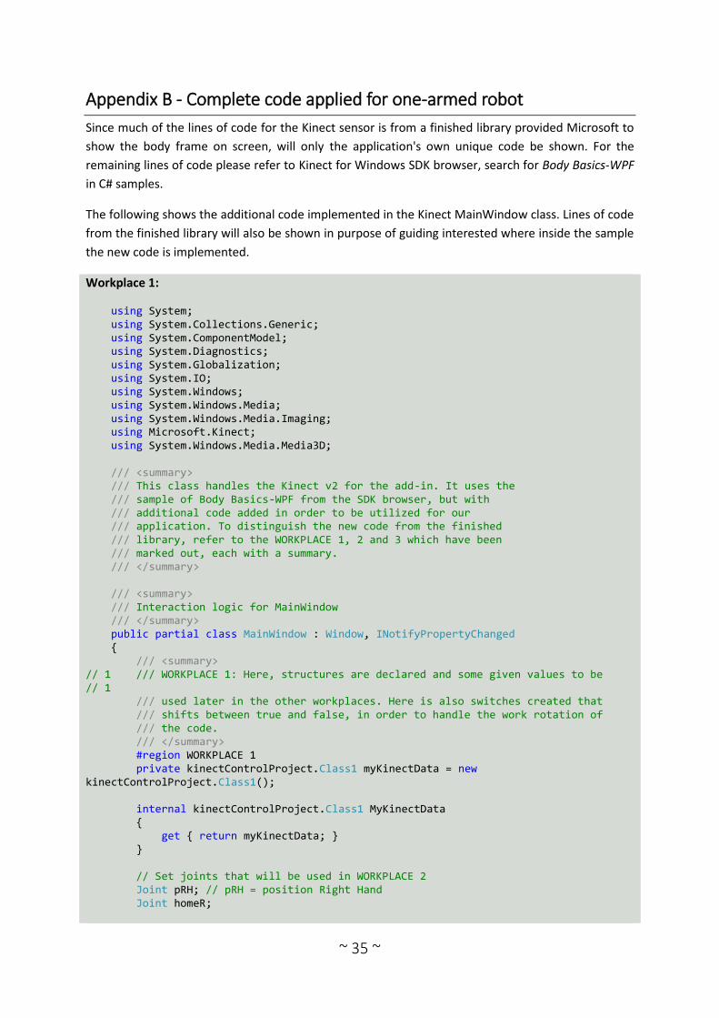
~ 35 ~
Appendix B - Complete code applied for one-armed robot
Since much of the lines of code for the Kinect sensor is from a finished library provided Microsoft to
show the body frame on screen, will only the application's own unique code be shown. For the
remaining lines of code please refer to Kinect for Windows SDK browser, search for Body Basics-WPF
in C# samples.
The following shows the additional code implemented in the Kinect MainWindow class. Lines of code
from the finished library will also be shown in purpose of guiding interested where inside the sample
the new code is implemented.
Workplace 1: using System; using System.Collections.Generic; using System.ComponentModel; using System.Diagnostics; using System.Globalization; using System.IO; using System.Windows; using System.Windows.Media; using System.Windows.Media.Imaging; using Microsoft.Kinect; using System.Windows.Media.Media3D; /// <summary> /// This class handles the Kinect v2 for the add-in. It uses the /// sample of Body Basics-WPF from the SDK browser, but with /// additional code added in order to be utilized for our /// application. To distinguish the new code from the finished /// library, refer to the WORKPLACE 1, 2 and 3 which have been /// marked out, each with a summary. /// </summary> /// <summary> /// Interaction logic for MainWindow /// </summary> public partial class MainWindow : Window, INotifyPropertyChanged { /// <summary> // 1 /// WORKPLACE 1: Here, structures are declared and some given values to be // 1 /// used later in the other workplaces. Here is also switches created that /// shifts between true and false, in order to handle the work rotation of /// the code. /// </summary> #region WORKPLACE 1 private kinectControlProject.Class1 myKinectData = new kinectControlProject.Class1(); internal kinectControlProject.Class1 MyKinectData { get { return myKinectData; } } // Set joints that will be used in WORKPLACE 2 Joint pRH; // pRH = position Right Hand Joint homeR;
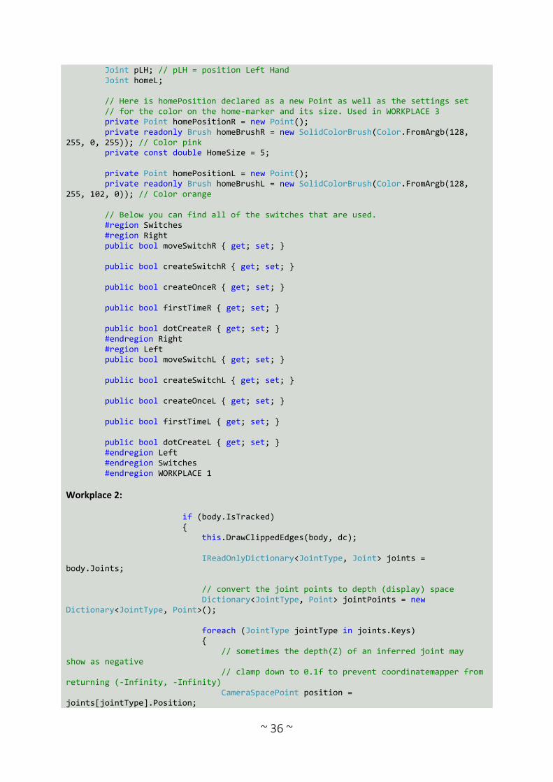
~ 36 ~
Joint pLH; // pLH = position Left Hand Joint homeL; // Here is homePosition declared as a new Point as well as the settings set // for the color on the home-marker and its size. Used in WORKPLACE 3 private Point homePositionR = new Point(); private readonly Brush homeBrushR = new SolidColorBrush(Color.FromArgb(128, 255, 0, 255)); // Color pink private const double HomeSize = 5; private Point homePositionL = new Point(); private readonly Brush homeBrushL = new SolidColorBrush(Color.FromArgb(128, 255, 102, 0)); // Color orange // Below you can find all of the switches that are used. #region Switches #region Right public bool moveSwitchR { get; set; } public bool createSwitchR { get; set; } public bool createOnceR { get; set; } public bool firstTimeR { get; set; } public bool dotCreateR { get; set; } #endregion Right #region Left public bool moveSwitchL { get; set; } public bool createSwitchL { get; set; } public bool createOnceL { get; set; } public bool firstTimeL { get; set; } public bool dotCreateL { get; set; } #endregion Left #endregion Switches #endregion WORKPLACE 1
Workplace 2: if (body.IsTracked) { this.DrawClippedEdges(body, dc); IReadOnlyDictionary<JointType, Joint> joints = body.Joints; // convert the joint points to depth (display) space Dictionary<JointType, Point> jointPoints = new Dictionary<JointType, Point>(); foreach (JointType jointType in joints.Keys) { // sometimes the depth(Z) of an inferred joint may show as negative // clamp down to 0.1f to prevent coordinatemapper from returning (-Infinity, -Infinity) CameraSpacePoint position = joints[jointType].Position;
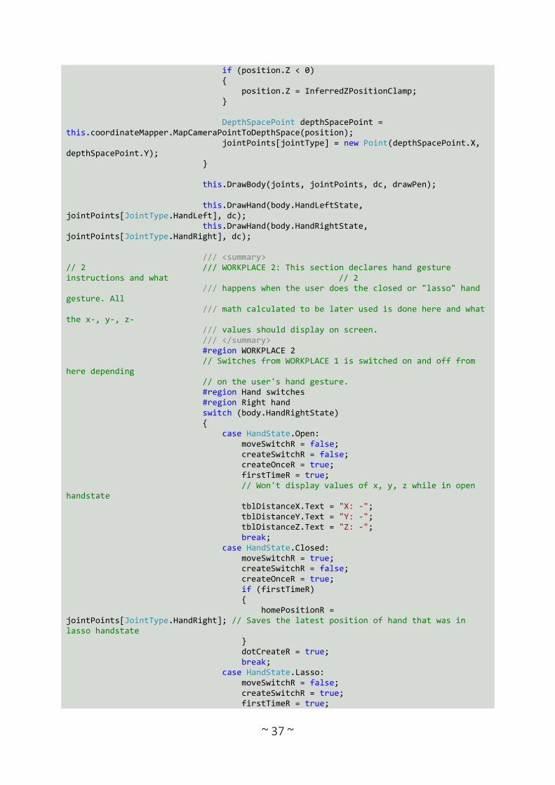
~ 37 ~
if (position.Z < 0) { position.Z = InferredZPositionClamp; } DepthSpacePoint depthSpacePoint = this.coordinateMapper.MapCameraPointToDepthSpace(position); jointPoints[jointType] = new Point(depthSpacePoint.X, depthSpacePoint.Y); } this.DrawBody(joints, jointPoints, dc, drawPen); this.DrawHand(body.HandLeftState, jointPoints[JointType.HandLeft], dc); this.DrawHand(body.HandRightState, jointPoints[JointType.HandRight], dc); /// <summary> // 2 /// WORKPLACE 2: This section declares hand gesture instructions and what // 2 /// happens when the user does the closed or "lasso" hand gesture. All /// math calculated to be later used is done here and what the x-, y-, z- /// values should display on screen. /// </summary> #region WORKPLACE 2 // Switches from WORKPLACE 1 is switched on and off from here depending // on the user's hand gesture. #region Hand switches #region Right hand switch (body.HandRightState) { case HandState.Open: moveSwitchR = false; createSwitchR = false; createOnceR = true; firstTimeR = true; // Won't display values of x, y, z while in open handstate tblDistanceX.Text = "X: -"; tblDistanceY.Text = "Y: -"; tblDistanceZ.Text = "Z: -"; break; case HandState.Closed: moveSwitchR = true; createSwitchR = false; createOnceR = true; if (firstTimeR) { homePositionR = jointPoints[JointType.HandRight]; // Saves the latest position of hand that was in lasso handstate } dotCreateR = true; break; case HandState.Lasso: moveSwitchR = false; createSwitchR = true; firstTimeR = true;
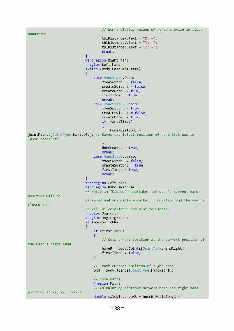
~ 38 ~
// Won't display values of x, y, z while in lasso handstate tblDistanceX.Text = "X: -"; tblDistanceY.Text = "Y: -"; tblDistanceZ.Text = "Z: -"; break; } #endregion Right hand #region Left hand switch (body.HandLeftState) { case HandState.Open: moveSwitchL = false; createSwitchL = false; createOnceL = true; firstTimeL = true; break; case HandState.Closed: moveSwitchL = true; createSwitchL = false; createOnceL = true; if (firstTimeL) { homePositionL = jointPoints[JointType.HandLeft]; // Saves the latest position of hand that was in lasso handstate } dotCreateL = true; break; case HandState.Lasso: moveSwitchL = false; createSwitchL = true; firstTimeL = true; break; } #endregion Left hand #endregion Hand switches // While in "Closed" handstate, the user's current hand position will be // saved and any difference to its position and the user's closed hand // will be calculated and sent to Class1. #region Jog data #region Jog right arm if (moveSwitchR) { if (firstTimeR) { // Sets a home position at the current position of the user's right hand homeR = body.Joints[JointType.HandRight]; firstTimeR = false; } // Track current position of right hand pRH = body.Joints[JointType.HandRight]; // Some maths #region Maths // Calculating distance between home and right hand position in x-, y-, z-axis double calcDistanceXR = homeR.Position.X -

~ 39 ~
pRH.Position.X; double calcDistanceYR = (homeR.Position.Y - pRH.Position.Y) * (-1); double calcDistanceZR = homeR.Position.Z - pRH.Position.Z; // Rounding down decimal values and display x-, y-, z-values on screen, according to the robot coordinate system double distanceXR = Math.Round(calcDistanceXR, 2); double distanceYR = Math.Round(calcDistanceYR, 2); double distanceZR = Math.Round(calcDistanceZR, 2); tblDistanceX.Text = "X: " + distanceZR.ToString() + "m"; tblDistanceY.Text = "Y: " + distanceXR.ToString() + "m"; tblDistanceZ.Text = "Z: " + distanceYR.ToString() + "m"; // Saves the x-, y-, z- values to 'transR', used for jogging the robot. For the Kinect and the robot to be able // to work within the same coordinate system, the x-, y-, z-translation is sent in a different order. ABB.Robotics.Math.Vector3 transR = new ABB.Robotics.Math.Vector3(distanceZR, distanceXR, distanceYR); // An attempt of implementing orientation control to the robot through the Kinect, but too sensitive. Isn't used // in this final prototype but kept here for possible further work on this project. #region Orientation Vector4 orientation = body.JointOrientations[JointType.HandRight].Orientation; Vector4 parentOrientation = body.JointOrientations[JointType.WristRight].Orientation; ABB.Robotics.Math.Quaternion quat = new ABB.Robotics.Math.Quaternion(orientation.X, orientation.Y, orientation.Z, orientation.W); ABB.Robotics.Math.Quaternion parentQuat = new ABB.Robotics.Math.Quaternion(parentOrientation.X, parentOrientation.Y, parentOrientation.Z, parentOrientation.W); #endregion Orientation #endregion Maths // Initiates the jogging procedure in Class1 and sends with it the calculated distance data (quat and parentQuat // isn't being used). MyKinectData.JogRobot(transR, quat, parentQuat); } #endregion Jog right arm #region Jog left arm if (moveSwitchL) { if (firstTimeL) { // Sets a home position at the current position of the user's left hand homeL = body.Joints[JointType.HandLeft]; firstTimeL = false; } // Track current position of left hand

~ 40 ~
pLH = body.Joints[JointType.HandLeft]; // Some maths #region Maths // Calculating distance between home and left hand position in x-, y-, z-axis double calcDistanceXL = (homeL.Position.X - pLH.Position.X); double calcDistanceYL = (homeL.Position.Y - pLH.Position.Y) * (-1); double calcDistanceZL = homeL.Position.Z - pLH.Position.Z; // Rounding down decimal values and display x-, y-, z-values on screen, according to the robot coordinate system double distanceXL = Math.Round(calcDistanceXL, 2); double distanceYL = Math.Round(calcDistanceYL, 2); double distanceZL = Math.Round(calcDistanceZL, 2); // Saves the x-, y-, z- values to 'transL', used for jogging the robot. For the Kinect and the robot to be able // to work within the same coordinate system, the x-, y-, z-translation is sent in a different order. ABB.Robotics.Math.Vector3 transL = new ABB.Robotics.Math.Vector3(distanceZL, distanceXL, distanceYL); // An attempt of implementing orientation control to the robot through the Kinect, but too sensitive. Isn't used // in this final prototype but kept here for possible further work on this project. #region Orientation Vector4 orientation = body.JointOrientations[JointType.HandRight].Orientation; Vector4 parentOrientation = body.JointOrientations[JointType.WristRight].Orientation; ABB.Robotics.Math.Quaternion quat = new ABB.Robotics.Math.Quaternion(orientation.X, orientation.Y, orientation.Z, orientation.W); ABB.Robotics.Math.Quaternion parentQuat = new ABB.Robotics.Math.Quaternion(parentOrientation.X, parentOrientation.Y, parentOrientation.Z, parentOrientation.W); #endregion Orientation #endregion Maths // Initiates the jogging procedure in Class1 and sends with it the calculated distance data (quat and parentQuat // isn't being used). MyKinectData.JogRobot(transL, quat, parentQuat); } #endregion Jog left arm #endregion Jog data // When the user does a "Lasso" handstate, a new target will be created, // described in CreateTargets in Class1. #region Create target #region right if (createSwitchR) { if (createOnceR) { MyKinectData.CreateTargets();
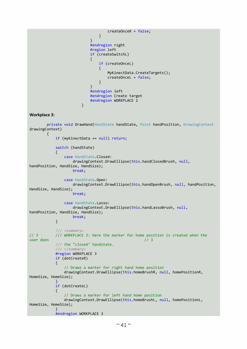
~ 41 ~
createOnceR = false; } } #endregion right #region left if (createSwitchL) { if (createOnceL) { MyKinectData.CreateTargets(); createOnceL = false; } } #endregion left #endregion Create target #endregion WORKPLACE 2 }
Workplace 3: private void DrawHand(HandState handState, Point handPosition, DrawingContext drawingContext) { if (myKinectData == null) return; switch (handState) { case HandState.Closed: drawingContext.DrawEllipse(this.handClosedBrush, null, handPosition, HandSize, HandSize); break; case HandState.Open: drawingContext.DrawEllipse(this.handOpenBrush, null, handPosition, HandSize, HandSize); break; case HandState.Lasso: drawingContext.DrawEllipse(this.handLassoBrush, null, handPosition, HandSize, HandSize); break; } /// <summary> // 3 /// WORKPLACE 3: Here the marker for home position is created when the user does // 3 /// the "closed" handstate. /// </summary> #region WORKPLACE 3 if (dotCreateR) { // Draws a marker for right hand home position drawingContext.DrawEllipse(this.homeBrushR, null, homePositionR, HomeSize, HomeSize); } if (dotCreateL) { // Draws a marker for left hand home position drawingContext.DrawEllipse(this.homeBrushL, null, homePositionL, HomeSize, HomeSize); } #endregion WORKPLACE 3

~ 42 ~
}
Following code is Class1 which handles the implementation of the application to RobotStudio and the
manipulation of the robot.
using ABB.Robotics; using ABB.Robotics.Math; using ABB.Robotics.RobotStudio; using ABB.Robotics.RobotStudio.Controllers; using ABB.Robotics.RobotStudio.Environment; using ABB.Robotics.RobotStudio.Stations; using ABB.Robotics.RobotStudio.Stations.Forms; using Microsoft.Kinect; using System; using System.Collections.Generic; using System.ComponentModel; using System.Diagnostics; using System.Globalization; using System.IO; using System.Linq; using System.Text; using System.Threading.Tasks; using System.Windows; using System.Windows.Media; using System.Windows.Media.Imaging; namespace kinectControlProject { public class Class1 { public Microsoft.Samples.Kinect.BodyBasics.MainWindow myKinectWindow; // This is the entry point for the Add-In public static void AddinMain() { Class1 addin = new Class1(); addin.CreateButton(); } // Creating the button for the project #region CreateButton private void CreateButton() { //Begin UndoStep Project.UndoContext.BeginUndoStep("Add Buttons"); try { // Create a new tab. RibbonTab ribbonTab = new RibbonTab("Project", "Kinect"); UIEnvironment.RibbonTabs.Add(ribbonTab); // Make tab as active tab UIEnvironment.ActiveRibbonTab = ribbonTab; // Create a group for Kinect RibbonGroup ribbonGroup = new RibbonGroup("KinectDemo", "Robot programming"); // Create Kinect button CommandBarButton button = new CommandBarButton("KinectTrack", "Start

~ 43 ~
Kinect"); button.HelpText = "Teach instructions with the help of a Kinect. Close either right or left hand to move the robot, use lasso handstate to save current TCP as a target"; button.DefaultEnabled = true; ribbonGroup.Controls.Add(button); // Include Seperator between buttons CommandBarSeparator seperator = new CommandBarSeparator(); ribbonGroup.Controls.Add(seperator); // Create second Kinect button CommandBarButton buttonSecond = new CommandBarButton("KinectCreate", "Create Path"); buttonSecond.HelpText = "Create a path between existing targets"; buttonSecond.DefaultEnabled = true; ribbonGroup.Controls.Add(buttonSecond); // Set the size of the buttons RibbonControlLayout[] ribbonControlLayout = { RibbonControlLayout.Small, RibbonControlLayout.Large }; ribbonGroup.SetControlLayout(button, ribbonControlLayout[1]); ribbonGroup.SetControlLayout(buttonSecond, ribbonControlLayout[1]); // Add ribbon group to ribbon tab ribbonTab.Groups.Add(ribbonGroup); // Add an event handler button.UpdateCommandUI += new UpdateCommandUIEventHandler(button_UpdateCommandUI); buttonSecond.UpdateCommandUI += new UpdateCommandUIEventHandler(buttonSecond_UpdateCommandUI); // Add an event handler for pressing the buttons button.ExecuteCommand += new ExecuteCommandEventHandler(button_ExecuteCommand); buttonSecond.ExecuteCommand += new ExecuteCommandEventHandler(buttonSecond_ExecuteCommand); } catch (Exception ex) { Project.UndoContext.CancelUndoStep(CancelUndoStepType.Rollback); Logger.AddMessage(new LogMessage(ex.Message.ToString())); } finally { Project.UndoContext.EndUndoStep(); } } #endregion CreateButton // First button which starts the kinect #region First button private void button_ExecuteCommand(object sender, ExecuteCommandEventArgs e) { // RobotStudio sends a signal to activate the Kinect v2. It opens a window and shows the body tracking myKinectWindow = new Microsoft.Samples.Kinect.BodyBasics.MainWindow(); myKinectWindow.Show(); } private void button_UpdateCommandUI(object sender, UpdateCommandUIEventArgs e) {

~ 44 ~
// This enables the button, instead of "button1.Enabled = true". e.Enabled = true; } #endregion First button // Second button which creates the path #region Second button private void buttonSecond_ExecuteCommand(object sender, ExecuteCommandEventArgs e) { // When the second button is pushed, CreatePath will be initiated which creates a // path between targets that has been created CreatePath(); } private void buttonSecond_UpdateCommandUI(object sender, UpdateCommandUIEventArgs e) { // This enables the button, instead of "button1.Enabled = true". e.Enabled = true; } #endregion Second button // While the user's hand is closed, the robot will replicate the user's hand movement #region JogRobot public void JogRobot(ABB.Robotics.Math.Vector3 trans, ABB.Robotics.Math.Quaternion rot, ABB.Robotics.Math.Quaternion parentRot) { Station stn = Station.ActiveStation; // Identify the mechanism of the robot Mechanism mech = stn.FindGraphicComponentsByType(typeof(Mechanism))[0] as Mechanism; Matrix4 newTCP = stn.ActiveTask.ActiveTool.Frame.GlobalMatrix; newTCP.Translate(trans.x / 50, trans.y / 50, trans.z / 50); // New TCP values are set here based on the calculated data from Kinect #region Rotation (WIP) // Take the relative rotation between the two quaternions (WIP) /* parentRot.Inverse(); Quaternion relRot = parentRot * rot; Vector3 euler = relRot.EulerZYX; euler.x /= 100; euler.y /= 100; euler.z /= 100; Matrix4 newModifiedRot = Matrix4.Identity; newModifiedRot.EulerZYX = euler; newTCP = newTCP * newModifiedRot; */ // End rotation #endregion Rotation (WIP) double[] jv; if (mech.CalculateInverseKinematics(newTCP, Matrix4.Identity, false, out jv)) { // Here the robot arm moves to its new position mech.SetJointValues(jv, false); Station.UpdateGraphics(true);
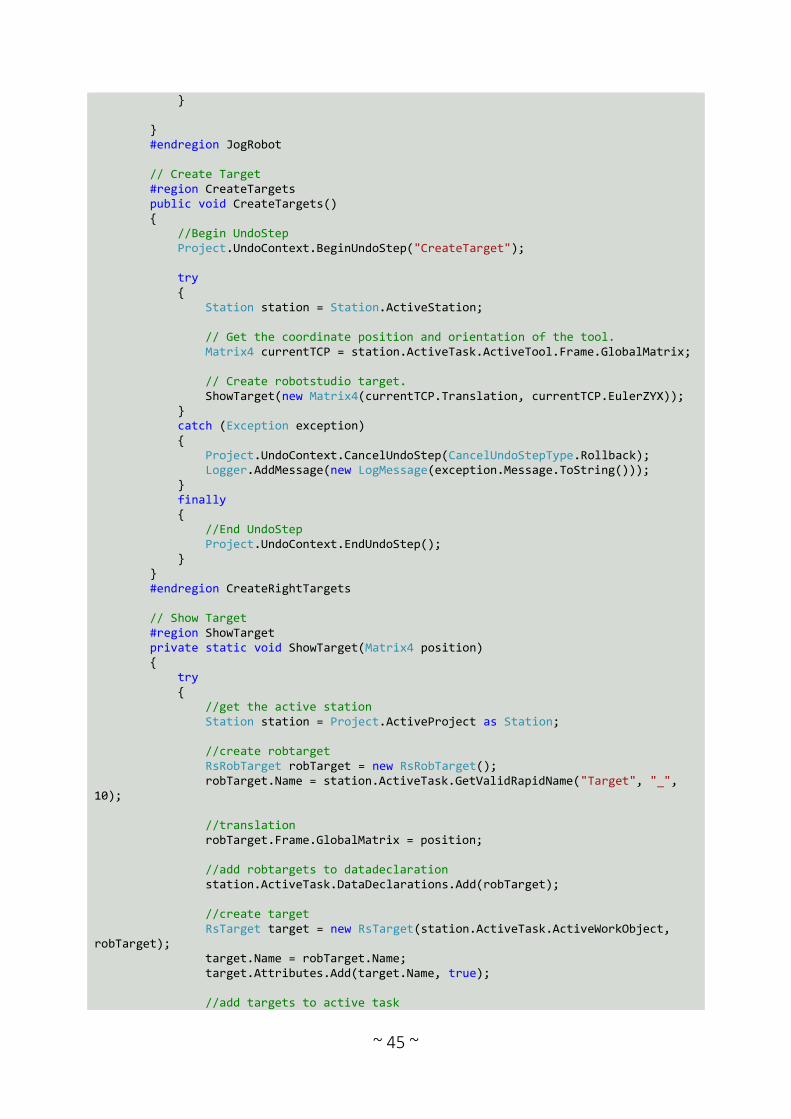
~ 45 ~
} } #endregion JogRobot // Create Target #region CreateTargets public void CreateTargets() { //Begin UndoStep Project.UndoContext.BeginUndoStep("CreateTarget"); try { Station station = Station.ActiveStation; // Get the coordinate position and orientation of the tool. Matrix4 currentTCP = station.ActiveTask.ActiveTool.Frame.GlobalMatrix; // Create robotstudio target. ShowTarget(new Matrix4(currentTCP.Translation, currentTCP.EulerZYX)); } catch (Exception exception) { Project.UndoContext.CancelUndoStep(CancelUndoStepType.Rollback); Logger.AddMessage(new LogMessage(exception.Message.ToString())); } finally { //End UndoStep Project.UndoContext.EndUndoStep(); } } #endregion CreateRightTargets // Show Target #region ShowTarget private static void ShowTarget(Matrix4 position) { try { //get the active station Station station = Project.ActiveProject as Station; //create robtarget RsRobTarget robTarget = new RsRobTarget(); robTarget.Name = station.ActiveTask.GetValidRapidName("Target", "_", 10); //translation robTarget.Frame.GlobalMatrix = position; //add robtargets to datadeclaration station.ActiveTask.DataDeclarations.Add(robTarget); //create target RsTarget target = new RsTarget(station.ActiveTask.ActiveWorkObject, robTarget); target.Name = robTarget.Name; target.Attributes.Add(target.Name, true); //add targets to active task
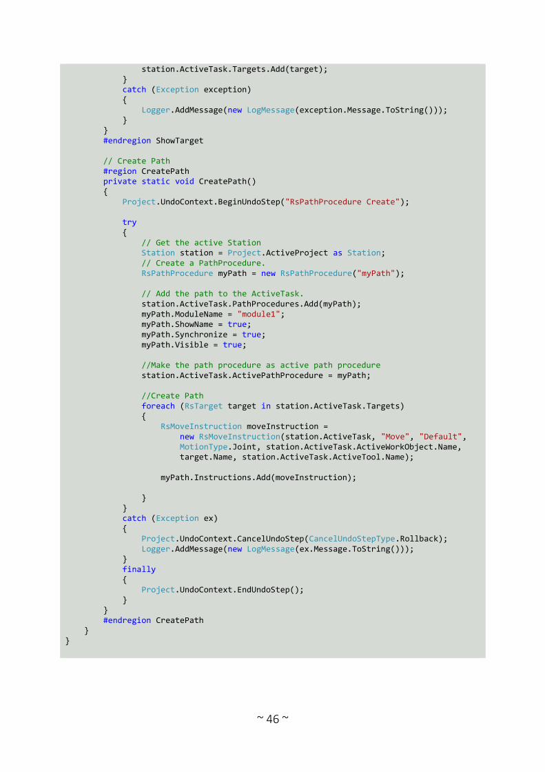
~ 46 ~
station.ActiveTask.Targets.Add(target); } catch (Exception exception) { Logger.AddMessage(new LogMessage(exception.Message.ToString())); } } #endregion ShowTarget // Create Path #region CreatePath private static void CreatePath() { Project.UndoContext.BeginUndoStep("RsPathProcedure Create"); try { // Get the active Station Station station = Project.ActiveProject as Station; // Create a PathProcedure. RsPathProcedure myPath = new RsPathProcedure("myPath"); // Add the path to the ActiveTask. station.ActiveTask.PathProcedures.Add(myPath); myPath.ModuleName = "module1"; myPath.ShowName = true; myPath.Synchronize = true; myPath.Visible = true; //Make the path procedure as active path procedure station.ActiveTask.ActivePathProcedure = myPath; //Create Path foreach (RsTarget target in station.ActiveTask.Targets) { RsMoveInstruction moveInstruction = new RsMoveInstruction(station.ActiveTask, "Move", "Default", MotionType.Joint, station.ActiveTask.ActiveWorkObject.Name, target.Name, station.ActiveTask.ActiveTool.Name); myPath.Instructions.Add(moveInstruction); } } catch (Exception ex) { Project.UndoContext.CancelUndoStep(CancelUndoStepType.Rollback); Logger.AddMessage(new LogMessage(ex.Message.ToString())); } finally { Project.UndoContext.EndUndoStep(); } } #endregion CreatePath } }
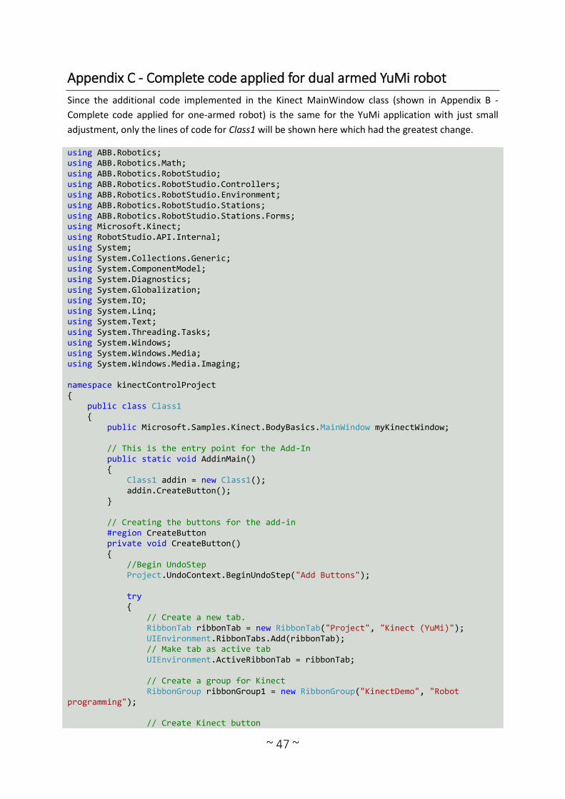
~ 47 ~
Appendix C - Complete code applied for dual armed YuMi robot
Since the additional code implemented in the Kinect MainWindow class (shown in Appendix B -
Complete code applied for one-armed robot) is the same for the YuMi application with just small
adjustment, only the lines of code for Class1 will be shown here which had the greatest change.
using ABB.Robotics; using ABB.Robotics.Math; using ABB.Robotics.RobotStudio; using ABB.Robotics.RobotStudio.Controllers; using ABB.Robotics.RobotStudio.Environment; using ABB.Robotics.RobotStudio.Stations; using ABB.Robotics.RobotStudio.Stations.Forms; using Microsoft.Kinect; using RobotStudio.API.Internal; using System; using System.Collections.Generic; using System.ComponentModel; using System.Diagnostics; using System.Globalization; using System.IO; using System.Linq; using System.Text; using System.Threading.Tasks; using System.Windows; using System.Windows.Media; using System.Windows.Media.Imaging; namespace kinectControlProject { public class Class1 { public Microsoft.Samples.Kinect.BodyBasics.MainWindow myKinectWindow; // This is the entry point for the Add-In public static void AddinMain() { Class1 addin = new Class1(); addin.CreateButton(); } // Creating the buttons for the add-in #region CreateButton private void CreateButton() { //Begin UndoStep Project.UndoContext.BeginUndoStep("Add Buttons"); try { // Create a new tab. RibbonTab ribbonTab = new RibbonTab("Project", "Kinect (YuMi)"); UIEnvironment.RibbonTabs.Add(ribbonTab); // Make tab as active tab UIEnvironment.ActiveRibbonTab = ribbonTab; // Create a group for Kinect RibbonGroup ribbonGroup1 = new RibbonGroup("KinectDemo", "Robot programming"); // Create Kinect button

~ 48 ~
CommandBarButton button = new CommandBarButton("KinectTrack", "Start Kinect"); button.HelpText = "Teach instructions with the help of a Kinect. Close either right or left hand to move the corresponding arm of the robot, use lasso handstate to save current TCP as a target"; button.DefaultEnabled = true; ribbonGroup1.Controls.Add(button); // Create a group for YuMi Path RibbonGroup ribbonGroup2 = new RibbonGroup("YuMiPath", "Create Path"); // Create YuMi right arm button CommandBarButton buttonSecond = new CommandBarButton("PathRight", "Right arm path"); buttonSecond.HelpText = "Create a path between the right arm's existing targets"; buttonSecond.DefaultEnabled = true; ribbonGroup2.Controls.Add(buttonSecond); // Include Seperator between buttons CommandBarSeparator seperator = new CommandBarSeparator(); ribbonGroup2.Controls.Add(seperator); // Create YuMi left arm button CommandBarButton buttonThird = new CommandBarButton("PathLeft", "Left arm path"); buttonThird.HelpText = "Create a path between the left arm's existing targets"; buttonThird.DefaultEnabled = true; ribbonGroup2.Controls.Add(buttonThird); // Set the size of the buttons RibbonControlLayout[] ribbonControlLayout = { RibbonControlLayout.Small, RibbonControlLayout.Large }; ribbonGroup1.SetControlLayout(button, ribbonControlLayout[1]); ribbonGroup2.SetControlLayout(buttonSecond, ribbonControlLayout[1]); ribbonGroup2.SetControlLayout(buttonThird, ribbonControlLayout[1]); // Add ribbon groups to ribbon tab ribbonTab.Groups.Add(ribbonGroup1); ribbonTab.Groups.Add(ribbonGroup2); // Add an event handler button.UpdateCommandUI += new UpdateCommandUIEventHandler(button_UpdateCommandUI); buttonSecond.UpdateCommandUI += new UpdateCommandUIEventHandler(buttonSecond_UpdateCommandUI); buttonThird.UpdateCommandUI += new UpdateCommandUIEventHandler(buttonThird_UpdateCommandUI); // Add an event handler for pressing the buttons button.ExecuteCommand += new ExecuteCommandEventHandler(button_ExecuteCommand); buttonSecond.ExecuteCommand += new ExecuteCommandEventHandler(buttonSecond_ExecuteCommand); buttonThird.ExecuteCommand += new ExecuteCommandEventHandler(buttonThird_ExecuteCommand); } catch (Exception ex) { Project.UndoContext.CancelUndoStep(CancelUndoStepType.Rollback); Logger.AddMessage(new LogMessage(ex.Message.ToString())); }

~ 49 ~
finally { Project.UndoContext.EndUndoStep(); } } #endregion CreateButton // First button which starts the kinect #region First button private void button_ExecuteCommand(object sender, ExecuteCommandEventArgs e) { // RobotStudio sends a signal to activate the Kinect v2. It opens a window and shows the body tracking myKinectWindow = new Microsoft.Samples.Kinect.BodyBasics.MainWindow(); myKinectWindow.Show(); } private void button_UpdateCommandUI(object sender, UpdateCommandUIEventArgs e) { // This enables the button, instead of "button1.Enabled = true". e.Enabled = true; } #endregion First button // Second button which creates the right arm path #region Second button private void buttonSecond_ExecuteCommand(object sender, ExecuteCommandEventArgs e) { // When the second button is pushed, CreatePath will be initiated which creates a // path between targets that has been created for the right arm CreatePathRight(); } private void buttonSecond_UpdateCommandUI(object sender, UpdateCommandUIEventArgs e) { // This enables the button, instead of "button1.Enabled = true". e.Enabled = true; } #endregion Second button // Third button which creates the left arm path #region Third button private void buttonThird_ExecuteCommand(object sender, ExecuteCommandEventArgs e) { // When the second button is pushed, CreatePath will be initiated which creates a // path between targets that has been created for the left arm CreatePathLeft(); } private void buttonThird_UpdateCommandUI(object sender, UpdateCommandUIEventArgs e) { // This enables the button, instead of "button1.Enabled = true". e.Enabled = true; } #endregion Third button

~ 50 ~
// While the user's hand is closed, the robot will replicate the user's hand movement #region JogRobot Right public void JogRightRobot(ABB.Robotics.Math.Vector3 transR, ABB.Robotics.Math.Quaternion rot, ABB.Robotics.Math.Quaternion parentRot) { Station stn = Station.ActiveStation; // Get the two robots, identify the left and right robot by name Mechanism leftYuMi = null; Mechanism rightYuMi = null; foreach (Mechanism mech in stn.FindGraphicComponentsByType(typeof(Mechanism))) { if (mech.MechanismType == MechanismType.Robot && mech.ModelName.ToUpper().Contains("IRB14000")) { // This is a YuMi Robot if (mech.ModelName.ToUpper().Contains("_L")) { leftYuMi = mech; } else if (mech.ModelName.ToUpper().Contains("_R")) { rightYuMi = mech; } } } Matrix4 rightYuMiCurrentTCP = rightYuMi.Task.ActiveTool.Frame.GlobalMatrix; rightYuMiCurrentTCP.Translate(transR.x / 50, transR.y / 50, transR.z / 50); // New TCP values are set here based on the calculated data from Kinect double[] jv; double[] integratedjv = null; int nNoOfIntegratedUnits = 0; Matrix4 refplane = new Matrix4(); Matrix4 armplane = new Matrix4(); double armangle = 0, length = 0; int status = 0; if (ControllerHelper.GetArmPlaneInfo(rightYuMi, out refplane, out armplane, out armangle, out length, out status)) { // This is how it works for multiaxis robots, the armangle is in thea eax_a position in the robtarget nNoOfIntegratedUnits = 1; integratedjv = new double[nNoOfIntegratedUnits]; integratedjv[0] = armangle; } if (rightYuMi.CalculateInverseKinematics(rightYuMiCurrentTCP, rightYuMi.GetJointValues(), integratedjv, Matrix4.Identity, false, out jv)) { // Here the robot arm moves to its new position rightYuMi.SetJointValues(jv, false); Station.UpdateGraphics(true); } } #endregion JogRobot Right #region JogRobot Left public void JogLeftRobot(ABB.Robotics.Math.Vector3 transL, ABB.Robotics.Math.Quaternion rot, ABB.Robotics.Math.Quaternion parentRot)
~ 51 ~
{ Station stn = Station.ActiveStation; // Get the two robots, identify the left and right robot by name Mechanism leftYuMi = null; Mechanism rightYuMi = null; foreach (Mechanism mech in stn.FindGraphicComponentsByType(typeof(Mechanism))) { if (mech.MechanismType == MechanismType.Robot && mech.ModelName.ToUpper().Contains("IRB14000")) { // This is a YuMi Robot if (mech.ModelName.ToUpper().Contains("_L")) { leftYuMi = mech; } else if (mech.ModelName.ToUpper().Contains("_R")) { rightYuMi = mech; } } } Matrix4 leftYuMiCurrentTCP = leftYuMi.Task.ActiveTool.Frame.GlobalMatrix; leftYuMiCurrentTCP.Translate(transL.x / 50, transL.y / 50, transL.z / 50); // New TCP values are set here based on the calculated data from Kinect double[] jv; double[] integratedjv = null; int nNoOfIntegratedUnits = 0; Matrix4 refplane = new Matrix4(); Matrix4 armplane = new Matrix4(); double armangle = 0, length = 0; int status = 0; if (ControllerHelper.GetArmPlaneInfo(leftYuMi, out refplane, out armplane, out armangle, out length, out status)) { // This is how it works for multiaxis robots, the armangle is in thea eax_a position in the robtarget nNoOfIntegratedUnits = 1; integratedjv = new double[nNoOfIntegratedUnits]; integratedjv[0] = armangle; } if (leftYuMi.CalculateInverseKinematics(leftYuMiCurrentTCP, leftYuMi.GetJointValues(), integratedjv, Matrix4.Identity, false, out jv)) { // Here the robot arm moves to its new position leftYuMi.SetJointValues(jv, false); Station.UpdateGraphics(true); } } #endregion JogRobot Left // Create Target #region CreateTargets Right public void CreateTargetsR() { //Begin UndoStep Project.UndoContext.BeginUndoStep("CreateTarget"); try
~ 52 ~
{ Station station = Station.ActiveStation; //get the two robots, identify the left and right robot by name Mechanism leftYuMi = null; Mechanism rightYuMi = null; foreach (Mechanism mech in station.FindGraphicComponentsByType(typeof(Mechanism))) { if (mech.MechanismType == MechanismType.Robot && mech.ModelName.ToUpper().Contains("IRB14000")) { //this is a YuMi Robot if (mech.ModelName.ToUpper().Contains("_L")) { leftYuMi = mech; } else if (mech.ModelName.ToUpper().Contains("_R")) { rightYuMi = mech; } } } // Get the coordinate position and orientation of the right tool. Matrix4 rightYuMiCurrentTCP = rightYuMi.Task.ActiveTool.Frame.GlobalMatrix; // Create robotstudio target. ShowTargetRight(new Matrix4(rightYuMiCurrentTCP.Translation, rightYuMiCurrentTCP.EulerZYX)); } catch (Exception exception) { Project.UndoContext.CancelUndoStep(CancelUndoStepType.Rollback); Logger.AddMessage(new LogMessage(exception.Message.ToString())); } finally { //End UndoStep Project.UndoContext.EndUndoStep(); } } #endregion CreateTargets Right #region CreateTargets Left public void CreateTargetsL() { //Begin UndoStep Project.UndoContext.BeginUndoStep("CreateTarget"); try { Station station = Station.ActiveStation; //get the two robots, identify the left and right robot by name Mechanism leftYuMi = null; Mechanism rightYuMi = null; foreach (Mechanism mech in station.FindGraphicComponentsByType(typeof(Mechanism))) { if (mech.MechanismType == MechanismType.Robot && mech.ModelName.ToUpper().Contains("IRB14000"))

~ 53 ~
{ //this is a YuMi Robot if (mech.ModelName.ToUpper().Contains("_L")) { leftYuMi = mech; } else if (mech.ModelName.ToUpper().Contains("_R")) { rightYuMi = mech; } } } // Get the coordinate position and orientation of the left tool. Matrix4 leftYuMiCurrentTCP = leftYuMi.Task.ActiveTool.Frame.GlobalMatrix; // Create robotstudio target. ShowTargetLeft(new Matrix4(leftYuMiCurrentTCP.Translation, leftYuMiCurrentTCP.EulerZYX)); } catch (Exception exception) { Project.UndoContext.CancelUndoStep(CancelUndoStepType.Rollback); Logger.AddMessage(new LogMessage(exception.Message.ToString())); } finally { //End UndoStep Project.UndoContext.EndUndoStep(); } } #endregion CreateTargets Left // Show Target #region ShowTargetRight private static void ShowTargetRight(Matrix4 position) { try { //get the active station Station station = Project.ActiveProject as Station; //get the two robots, identify the left and right robot by name Mechanism leftYuMi = null; Mechanism rightYuMi = null; foreach (Mechanism mech in station.FindGraphicComponentsByType(typeof(Mechanism))) { if (mech.MechanismType == MechanismType.Robot && mech.ModelName.ToUpper().Contains("IRB14000")) { //this is a YuMi Robot if (mech.ModelName.ToUpper().Contains("_L")) { leftYuMi = mech; } else if (mech.ModelName.ToUpper().Contains("_R")) { rightYuMi = mech; } }

~ 54 ~
} //create robtarget RsRobTarget robTargetRight = new RsRobTarget(); robTargetRight.Name = rightYuMi.Task.GetValidRapidName("Target", "_", 10); //translation robTargetRight.Frame.GlobalMatrix = position; //add robtargets to datadeclaration rightYuMi.Task.DataDeclarations.Add(robTargetRight); //create target RsTarget targetRight = new RsTarget(rightYuMi.Task.ActiveWorkObject, robTargetRight); targetRight.Name = robTargetRight.Name; targetRight.Attributes.Add(targetRight.Name, true); //add targets to active task rightYuMi.Task.Targets.Add(targetRight); } catch (Exception exception) { Logger.AddMessage(new LogMessage(exception.Message.ToString())); } } #endregion ShowTargetRight #region ShowTargetLeft private static void ShowTargetLeft(Matrix4 position) { try { //get the active station Station station = Project.ActiveProject as Station; //get the two robots, identify the left and right robot by name Mechanism leftYuMi = null; Mechanism rightYuMi = null; foreach (Mechanism mech in station.FindGraphicComponentsByType(typeof(Mechanism))) { if (mech.MechanismType == MechanismType.Robot && mech.ModelName.ToUpper().Contains("IRB14000")) { //this is a YuMi Robot if (mech.ModelName.ToUpper().Contains("_L")) { leftYuMi = mech; } else if (mech.ModelName.ToUpper().Contains("_R")) { rightYuMi = mech; } } } //create robtarget RsRobTarget robTargetLeft = new RsRobTarget(); robTargetLeft.Name = leftYuMi.Task.GetValidRapidName("Target", "_", 10);

~ 55 ~
//translation robTargetLeft.Frame.GlobalMatrix = position; //add robtargets to datadeclaration leftYuMi.Task.DataDeclarations.Add(robTargetLeft); //create target RsTarget targetLeft = new RsTarget(leftYuMi.Task.ActiveWorkObject, robTargetLeft); targetLeft.Name = robTargetLeft.Name; targetLeft.Attributes.Add(targetLeft.Name, true); //add targets to active task leftYuMi.Task.Targets.Add(targetLeft); } catch (Exception exception) { Logger.AddMessage(new LogMessage(exception.Message.ToString())); } } #endregion ShowTargetLeft // Create Path #region CreatePathRight private static void CreatePathRight() { Project.UndoContext.BeginUndoStep("RsPathProcedure Create"); try { // Get the active Station Station station = Project.ActiveProject as Station; //get the two robots, identify the left and right robot by name Mechanism leftYuMi = null; Mechanism rightYuMi = null; foreach (Mechanism mech in station.FindGraphicComponentsByType(typeof(Mechanism))) { if (mech.MechanismType == MechanismType.Robot && mech.ModelName.ToUpper().Contains("IRB14000")) { //this is a YuMi Robot if (mech.ModelName.ToUpper().Contains("_L")) { leftYuMi = mech; } else if (mech.ModelName.ToUpper().Contains("_R")) { rightYuMi = mech; } } } // Create a PathProcedure. RsPathProcedure YuMiPathRight = new RsPathProcedure("myYuMiRight"); // Add the path to the ActiveTask. rightYuMi.Task.PathProcedures.Add(YuMiPathRight); YuMiPathRight.ModuleName = "module1"; YuMiPathRight.ShowName = true; YuMiPathRight.Synchronize = true;
~ 56 ~
YuMiPathRight.Visible = true; //Make the path procedure as active path procedure rightYuMi.Task.ActivePathProcedure = YuMiPathRight; //Create Path foreach (RsTarget target in rightYuMi.Task.Targets) { RsMoveInstruction moveInstruction = new RsMoveInstruction(rightYuMi.Task, "Move", "Default", MotionType.Joint, rightYuMi.Task.ActiveWorkObject.Name, target.Name, rightYuMi.Task.ActiveTool.Name); YuMiPathRight.Instructions.Add(moveInstruction); } } catch (Exception ex) { Project.UndoContext.CancelUndoStep(CancelUndoStepType.Rollback); Logger.AddMessage(new LogMessage(ex.Message.ToString())); } finally { Project.UndoContext.EndUndoStep(); } } #endregion CreatePathRight #region CreatePathLeft private static void CreatePathLeft() { Project.UndoContext.BeginUndoStep("RsPathProcedure Create"); try { // Get the active Station Station station = Project.ActiveProject as Station; //get the two robots, identify the left and right robot by name Mechanism leftYuMi = null; Mechanism rightYuMi = null; foreach (Mechanism mech in station.FindGraphicComponentsByType(typeof(Mechanism))) { if (mech.MechanismType == MechanismType.Robot && mech.ModelName.ToUpper().Contains("IRB14000")) { //this is a YuMi Robot if (mech.ModelName.ToUpper().Contains("_L")) { leftYuMi = mech; } else if (mech.ModelName.ToUpper().Contains("_R")) { rightYuMi = mech; } } } // Create a PathProcedure. RsPathProcedure YuMiPathLeft = new RsPathProcedure("myYuMiLeft");

~ 57 ~
// Add the path to the ActiveTask. leftYuMi.Task.PathProcedures.Add(YuMiPathLeft); YuMiPathLeft.ModuleName = "module1"; YuMiPathLeft.ShowName = true; YuMiPathLeft.Synchronize = true; YuMiPathLeft.Visible = true; //Make the path procedure as active path procedure leftYuMi.Task.ActivePathProcedure = YuMiPathLeft; //Create Path foreach (RsTarget target in leftYuMi.Task.Targets) { RsMoveInstruction moveInstruction = new RsMoveInstruction(leftYuMi.Task, "Move", "Default", MotionType.Joint, leftYuMi.Task.ActiveWorkObject.Name, target.Name, leftYuMi.Task.ActiveTool.Name); YuMiPathLeft.Instructions.Add(moveInstruction); } } catch (Exception ex) { Project.UndoContext.CancelUndoStep(CancelUndoStepType.Rollback); Logger.AddMessage(new LogMessage(ex.Message.ToString())); } finally { Project.UndoContext.EndUndoStep(); } } #endregion CreatePathLeft } }