virtual cloud computing effects and application of …calhoun: the nps institutional archive theses...
TRANSCRIPT

Calhoun: The NPS Institutional Archive
Theses and Dissertations Thesis Collection
2011-09
Virtual cloud computing effects and application of
hastily formed networks (HFN) for humanitarian
assistance/disaster relief (HA/DR) missions
Morris, Mark K.
Monterey, California. Naval Postgraduate School
http://hdl.handle.net/10945/5476

NAVAL
POSTGRADUATE SCHOOL
MONTEREY, CALIFORNIA
THESIS
Approved for public release; distribution is unlimited
VIRTUAL CLOUD COMPUTING: EFFECTS AND APPLICATION OF HASTILY FORMED NETWORKS
(HFN) FOR HUMANITARIAN ASSISTANCE/DISASTER RELIEF (HA/DR) MISSIONS
by
Mark K. Morris
September 2011
Thesis Co-Advisors: Albert Barreto Douglas MacKinnon Second Reader: Brian Steckler

THIS PAGE INTENTIONALLY LEFT BLANK
i
REPORT DOCUMENTATION PAGE Form Approved OMB No. 0704-0188 Public reporting burden for this collection of information is estimated to average 1 hour per response, including the time for reviewing instruction, searching existing data sources, gathering and maintaining the data needed, and completing and reviewing the collection of information. Send comments regarding this burden estimate or any other aspect of this collection of information, including suggestions for reducing this burden, to Washington headquarters Services, Directorate for Information Operations and Reports, 1215 Jefferson Davis Highway, Suite 1204, Arlington, VA 22202-4302, and to the Office of Management and Budget, Paperwork Reduction Project (0704-0188) Washington DC 20503. 1. AGENCY USE ONLY (Leave blank)
2. REPORT DATE September 2011
3. REPORT TYPE AND DATES COVERED Master’s Thesis
4. TITLE AND SUBTITLE Virtual Cloud Computing: Effects and Application of Hastily Formed Networks (HFN) for Humanitarian Assistance/Disaster Relief (HA/DR) Missions 6. AUTHOR(S) Mark K. Morris
5. FUNDING NUMBERS
7. PERFORMING ORGANIZATION NAME(S) AND ADDRESS(ES) Naval Postgraduate School Monterey, CA 93943-5000
8. PERFORMING ORGANIZATION REPORT NUMBER
9. SPONSORING /MONITORING AGENCY NAME(S) AND ADDRESS(ES) N/A
10. SPONSORING/MONITORING AGENCY REPORT NUMBER
11. SUPPLEMENTARY NOTES The views expressed in this thesis are those of the author and do not reflect the official policy or position of the Department of Defense or the U.S. Government. IRB Protocol number ______N.A.__________.
12a. DISTRIBUTION / AVAILABILITY STATEMENT Approved for public release; distribution is unlimited
12b. DISTRIBUTION CODE A
13. ABSTRACT (maximum 200 words)
Catastrophic events occur throughout the earth and first responders can benefit from improved Command and Control (C2). Currently, military C2 capabilities, though adequate in some settings, can be enhanced using virtual applications. This thesis seeks as its goals to analyze and transform present Hastily Formed Network (HFN) capabilities into a virtual HFN system, controlling for technology. We analyze this through leveraging the Naval Postgraduate School (NPS) HFN and Virtualization and Cloud Computing labs. The independent variables are defined as the current HFN architecture and Virtualization and Cloud Computing lab, and the dependent variables are defined as cost and hardware.
Through this research effort, we explore, and perhaps improve, HFN capabilities through available virtualization technologies. The additional technologies applied to the current HFN system may aid in the speed of connectivity to the World Wide Web and other mission-critical resources, thus promoting an enhanced C2 capability, and in turn saving lives during HA/DR missions. This research points the way for future researchers to continue leveraging virtualization technologies and cloud computing in HA/DR settings.
The thesis research conducted and distributed is in the area of networking and applied sciences in technology. The methodology and practices during the research utilized cutting-edge technology while testing performance capabilities of virtualized systems. The information gathering and research phase of this thesis directly applies elements of information systems analysis.
15. NUMBER OF PAGES
100
14. SUBJECT TERMS Hastily Formed Network, Virtualization Technology, Network Management, Satellite Terminals
16. PRICE CODE
17. SECURITY CLASSIFICATION OF REPORT
Unclassified
18. SECURITY CLASSIFICATION OF THIS PAGE
Unclassified
19. SECURITY CLASSIFICATION OF ABSTRACT
Unclassified
20. LIMITATION OF ABSTRACT
UU NSN 7540-01-280-5500 Standard Form 298 (Rev. 2-89) Prescribed by ANSI Std. 239-18

ii
THIS PAGE INTENTIONALLY LEFT BLANK

iii
Approved for public release; distribution is unlimited
VIRTUAL CLOUD COMPUTING: EFFECTS AND APPLICATION OF HASTILY FORMED NETWORKS (HFN) FOR HUMANITARIAN
ASSISTANCE/DISASTER RELIEF (HA/DR) MISSIONS
Mark K. Morris Captain, United States Marine Corps
B.S., Brigham Young University, 2003
Submitted in partial fulfillment of the requirements for the degree of
MASTER OF SCIENCE IN INFORMATION TECHNOLOGY MANAGEMENT
from the
NAVAL POSTGRADUATE SCHOOL September 2011
Author: Mark K. Morris
Approved by: Albert Barreto Thesis Co-Advisor Dr. Douglas MacKinnon Thesis Co-Advisor
Brian Steckler Second Reader
Dr. Dan Boger Chair, Department of Information Sciences

iv
THIS PAGE INTENTIONALLY LEFT BLANK

v
ABSTRACT
Catastrophic events occur throughout the earth and first responders can benefit from
improved Command and Control (C2). Currently, military C2 capabilities, though
adequate in some settings, can be enhanced using virtual applications. This thesis seeks
as its goals to analyze and transform present Hastily Formed Network (HFN) capabilities
into a virtual HFN system, controlling for technology. We analyze this through
leveraging the Naval Postgraduate School (NPS) HFN and Virtualization and Cloud
Computing labs. The independent variables are defined as the current HFN architecture
and Virtualization and Cloud Computing lab, and the dependent variables are defined as
cost and hardware.
Through this research effort, we explore, and perhaps improve, HFN capabilities
through available virtualization technologies. The additional technologies applied to the
current HFN system may aid in the speed of connectivity to the World Wide Web and
other mission-critical resources, thus promoting an enhanced C2 capability, and in turn
saving lives during HA/DR missions. This research points the way for future researchers
to continue leveraging virtualization technologies and cloud computing in HA/DR
settings.
The thesis research conducted and distributed is in the area of networking and
applied sciences in technology. The methodology and practices during the research
utilized cutting-edge technology while testing performance capabilities of virtualized
systems. The information gathering and research phase of this thesis directly applies
elements of information systems analysis.

vi
THIS PAGE INTENTIONALLY LEFT BLANK

vii
TABLE OF CONTENTS
I. INTRODUCTION........................................................................................................1 A. BACKGROUND ..............................................................................................1 B. SYSTEM EVOLUTION..................................................................................2 C. VIRTUALIZATION........................................................................................3 D. HASTILY FORMED NETWORKS ..............................................................5 E. DEFINITIONS .................................................................................................5 F. RESEARCH SCOPE.......................................................................................8 G. THESIS STRUCTURE ...................................................................................9
II. CASE STUDIES OF NATURAL DISASTERS ......................................................11 A. SEPTEMBER 11 TERRORIST ATTACKS...............................................11 B. HURRICANE KATRINA.............................................................................12 C. HAITI EARTHQUAKE................................................................................15
III. VIRTUALIZATION/CLOUD COMPUTING........................................................17 A. BACKGROUND ............................................................................................17 B. VIRTUAL DESKTOP INFRASTRUCTURE (VDI)..................................19 C. CLOUD COMPUTING.................................................................................25
IV. HASTILY FORMED NETWORKS ........................................................................29 A. BACKGROUND ............................................................................................29 B. HFN BUSINESS ARCHITECTURE ...........................................................31 C. MANPACK.....................................................................................................34
1. Flyaway Kit.........................................................................................34 2. Virtual Flyaway Kit (FLAK) ............................................................36
D. NETWORK ....................................................................................................37 1. Network Operating Center (NOC)...................................................37 2. Ad hoc Network ..................................................................................45
E. SATELLITE GATEWAYS...........................................................................46 1. BGAN..................................................................................................46 2. VSATs .................................................................................................47
V. SATELLITE MEASUREMENTS/REQUIREMENTS..........................................49 A. BGAN MEASUREMENTS...........................................................................49 B. VSAT–TACHYON EARTH TERMINAL MEASUREMENTS...............53 C. CHEETAH MEASUREMENTS ..................................................................57 D. AN-TSC 168 MEASUREMENTS ................................................................61
VI. ENHANCED VIRTUAL TECHNOLOGY .............................................................63 A. LOCAL CLOUD CAPABILITY..................................................................63 B. REGIONAL CLOUD CAPABILITY ..........................................................66
VII. CONCLUSION ..........................................................................................................69 A. LESSONS LEARNED (CLOUD MANAGEMENT)..................................69 B. A POTENTIAL WAY FORWARD (TACTICAL EMPLOYMENT)......71

viii
C. FUTURE STUDY...........................................................................................72
LIST OF REFERENCES......................................................................................................75
INITIAL DISTRIBUTION LIST .........................................................................................79

ix
LIST OF FIGURES
Figure 1. Hurricane Katrina Network Infrastructure.......................................................13 Figure 2. NPS Team Locations .......................................................................................14 Figure 3. OSI Model from CCNA (From CCNA, 2011) ...............................................17 Figure 4. Client-Server Architecture from Panologic (From Panologic, 2010)..............19 Figure 5. Thin client Architecture from Panologic (From Panologic, 2010) ..................21 Figure 6. Zero client Architecture from Panologic (From Panologic, 2010) ..................22 Figure 7. Thick client Speed............................................................................................23 Figure 8. Thin client Speed Factors.................................................................................24 Figure 9. Zero client Speed Factors.................................................................................24 Figure 10. The Internet Cloud (From Alkima, 2011).......................................................25 Figure 11. Cloud Computing Pyramid Architecture from Amazon (From Edge, 2011) ..26 Figure 12. Cloud Computing Basic Architecture (From Rajasekar, 2011)......................27 Figure 13. CISCO Network Emergency Response Vehicle (NERV) (From MCNC,
2009) ................................................................................................................35 Figure 14. Fly Away Kit (From Steckler & Meyer, 2010)...............................................36 Figure 15. Virtual Flyaway Kit .........................................................................................37 Figure 16. DopplerVUE Screen Shot ................................................................................38 Figure 17. SolarWinds IP Network Browser.....................................................................39 Figure 18. Network Sonar Discovery Wizard ...................................................................40 Figure 19. SolarWinds Subnet Query................................................................................41 Figure 20. SolarWinds Network Sonar Tool.....................................................................41 Figure 21. SolarWinds Chart Function of Network Sonar Tool .......................................42 Figure 22. SolarWinds Network Performance Monitor ....................................................43 Figure 23. Video and Observer Notepad...........................................................................44 Figure 24. Battle Field Medical Experiment .....................................................................45 Figure 25. Hughes 9201 BGAN........................................................................................49 Figure 26. BGAN Launchpad Connection Speeds............................................................50 Figure 27. BGAN Launchpad ...........................................................................................51 Figure 28. Hughes BGAN Speed Test using speedtest.net ...............................................52 Figure 29. Tachyon Earth Terminal ..................................................................................53 Figure 30. Trace-route of Tachyon connection.................................................................55 Figure 31. Cheetah Earth Terminal ...................................................................................57 Figure 32. Diagram of Connection from Florida to NPS..................................................58 Figure 33. IP Configuration Troubleshooting ...................................................................59 Figure 34. Typical Hastily Formed Network Architecture ...............................................60 Figure 35. Connection Between Avon Park, FL and NPS ................................................61 Figure 36. AN-TSC 168 ....................................................................................................61 Figure 37. GSOIS Virtual Environment............................................................................64 Figure 38. Rack 2 of GSOIS Virtual Environment ...........................................................65 Figure 39. MoJoJoJo Rack ................................................................................................67 Figure 40. Accessing Cloud Computing Lab ....................................................................68

x
THIS PAGE INTENTIONALLY LEFT BLANK

xi
LIST OF TABLES
Table 1. Agility Logic Matrix Considering Range, Time and Environmental Turbulence (From Sengupta, 2011) .................................................................32
Table 2. Four Logics for Enterprise Architecture (From Ross, Weill, & Robertson, 2006) ................................................................................................................33

xii
THIS PAGE INTENTIONALLY LEFT BLANK

xiii
LIST OF ACRONYMS AND ABBREVIATIONS
ACU Antenna Control Unit
APAN All Partners Access Network community.apan.org
AOR Area of Operations
BGAN Broadband Global Area Network
BPI Business Process Integration
BPS Business Process Standardization
C2 Command and Control
CHD Complex Humanitarian Disaster
CHE Complex Humanitarian Emergency
CHSC Container Handling System Corp
CIV-MIL REL Civilian–Military Relations
CMOC Civilian Military Operations Center
COTS Commercial Off-the-Shelf
DENCAP Dental Civic Action Program
DISA Defense Information System Agency
DJC2 Deployable Joint Command and Control
DoD Department of Defense
DOD INST 3000.05 DoD Procedures for Management of Information
EMP Electromagnetic Pulse
EOC Emergency Operations Center
FLAK Fly Away Kit check page 1—it’s one word there
FRS Family Radio Service
GAR General Assessment Report
GUI Graphical User Interface
HA/DR Humanitarian Assistance/Disaster Relief
HFN Hastily Formed Network
ICT Information and Communications Technology
IGO Independent Government Organization
IP Internet Protocol
IHC International Humanitarian Community

xiv
ITACS Information Technology and Communications Services
IO International Organizations
JCSE Joint Communications Support Element
JCSC Joint Communications Support Command
JTF Joint Task Force
kbps Kilo Bits Per Second
LOS Line of Sight
Mbps Mega Bits Per Second
MCIP Multinational Communications Interoperability Programs
MEDCAP Medical Civic Action Program
MIB Management Information Base
NAS Network Attached Storage
NERV Network Emergency Response Vehicle
NDU Network Data Unit
NGO Non-Governmental Organization
NOC Network Operating Center
NPS Naval Postgraduate School
UN United Nations
NRF National Response Framework
OES/EMA Operational Emergency Services/Emergency Management Agency
OEM Office of Emergency Management
OSD Office of the Secretary of Defense
OSI Open Systems Interconnection
PCOIP PC over IP
RRK Rapid Response Kit
SAR Satellite Access Request
SATCOM Satellite Communications
SIM Subscriber Identity Module
SOTM Satellite on the Move
SSTR Security, Stability, Transition, Reconstruction

xv
TELEMED Telemedicine
UN-OCHA United Nations-Office for the Coordination of Humanitarian Affairs
U.S. United States
USAID United States Agency for International Development
VoIP Voice over Internet Protocol
VPN Virtual Private Network
VSAT Very Small Aperture Satellite Terminal
VTC Video Teleconference Center
Wi-Fi Wireless Fidelity as defined by the industry
WiMAX Wireless Microwave Access
WTC World Trade Center
WWW World Wide Web

xvi
THIS PAGE INTENTIONALLY LEFT BLANK

xvii
ACKNOWLEDGMENTS
I must first thank my Lord and Savior for the time I have in this life to learn and
grow. I know that He has given me the strength, will, and knowledge to complete this
thesis.
I then want to thank my dear wife, Catherine, for her support and encouragement
throughout my time at the Naval Postgraduate School. You are my best friend and I am
blessed to have a wonderful wife such as you. I also want to thank my children,
Matthew, Ethan, and Maile, for the joy they add to my life.
I want to thank my advisors, Mr. Albert Barreto, Mr. Brian Steckler, and Dr.
Doug MacKinnon. Dr. MacKinnon, your insight, experience, and time have helped me
immensely in the formatting and structuring of my thesis. Mr. Barreto, your example,
patience, and passion for virtualization technologies helped me to pursue this thesis. I
have truly enjoyed the last two years working with you in the Virtualization/Cloud
Computing Lab. Mr. Steckler, your generosity, enthusiasm, and knowledge for Hastily
Formed Networks have epitomized excellence. Thank you for your kindness and
allowing me to work with so many different technologies in networking.
I want to thank others who have aided my thesis in one form or another; in
particular, Dr. Bordetsky, Dr. Sengupta, CISCO, L3 Communications, and Tachyon Inc.
Lastly, I want to thank the United States Marine Corps for allowing me to pursue
a higher education.

xviii
THIS PAGE INTENTIONALLY LEFT BLANK

1
I. INTRODUCTION
A. BACKGROUND
During the last decade the world has experienced a plethora of unexpected
disasters, many of which were natural, others man made, occurring in many different
forms but each taking many lives and leaving large geographic areas without
communications. On September 11, 2001, the World Trade Center (WTC) in New York
City was destroyed by terrorists, killing 2,749 people. On December 26, 2004, a
magnitude 9.1 earthquake in the Indian Ocean caused a deadly tsunami, killing 283,000
people. On August 29, 2005, the major, category-5 Hurricane Katrina slammed into the
gulf coast of the United States, knocking out all computer networks, electricity, and
communications over a 90,000-square-mile area (Denning, 2006). Each of these disasters
could have benefitted from a rapidly deployable communication technology that was
quickly mobilized and immediately employed. However, during each event, the rapidly
deployed technology was organized differently and setup time was difficult to predict.
Each of these events was driven by the immediate need to create a fast and efficient
network that would be able to support the “military, civilian government, nongovernment
organizations, U.S. Department of Defense (DoD), and Homeland Security” (Denning,
2006).
The Naval Postgraduate School (NPS) designed and created its own Hastily
Formed Network (HFN) capability and lab with the goals to “facilitate cooperation
between disparate groups, promote tools for collaboration, learn capacity to improvise,
and foster leadership in a network” during HA/DR missions (Denning, 2006).
Subsequently, this NPS HFN has deployed to several HA/DR events since being stood up
such as: Southeast Asia tsunami (2004), Hurricane Katrina (2005), USNS Comfort &
USNS Mercy (2006, 2007), and the Haiti Earthquake (2010) (Steckler & Meyer, 2010).
In addition to the people who deploy to disasters, the technology that comprises
the NPS HFN consists of rapidly deployable “flyaway” kits (FLAKs) that are assembled
from various communications equipment. These kits consist of rack mounted network

2
gear, Worldwide Interoperability for Microwave Access (WiMAX) antenna/ODU,
Meshed Wireless Fidelity (Wi-Fi) access points, Broadband Global Area Network
(BGAN) Satellite Data unit, Laptops, Satellite Phones, Family Radio Service (FRS)
radios, generators, solar panels and wind turbines, batteries, inverters, and transformers.
All of this equipment is lightweight, portable and self-sustaining (Lancaster, 2005).
NPS also has a virtual cloud computing laboratory located in Root Hall. This
laboratory holds three server racks, which are used to support several technology classes,
Intel-based servers, several terabytes of storage, and other networking hardware.
Currently, the capabilities of this laboratory have been underutilized and are capable of
much more. The virtualized infrastructure, when combined with the NPS HFN capability
appears to have immense, and as of yet, untapped potential.
This research will focus on joining virtual application technology with the NPS
HFN capability, and will analyze the ability of HFNs to host virtual networks and the
electronic bandwidth needed to accomplish this task. The effort of this research will
examine the hardware and the improvements needed for the virtual HFN to be effective.
The research conducted in this thesis will also test software application aided elements in
command and control and the measurement of the data transfer speed using the virtual
HFN in a rugged environment.
B. SYSTEM EVOLUTION
Evolution is a constant in all systems whether it pertains to ecological, biological,
or technological systems. Bacteria, for example, have epitomized evolution since the
beginning of life. Bacteria, one of the simplest forms of life, has continually evolved and
adapted to its environment throughout time. An example of bacteria’s resiliency is its
ability to develop traits, specifically cell walls, which provide a rigid exoskeleton to
overcome this threat to its existence (Navarre & Schneewind, 1999). The medical
profession has introduced various forms of antibiotics to fight bacteria; yet, this simple
organism has adapted and overcome every drug or antibiotic that has been directed
toward it and has subsequently become more robust in multiple environments. A Hastily
Formed Network must also adapt to the environment in which it is placed and overcome
3
varied obstacles placed in its way. Examples of obstacles an HFN faces include, but are
not limited to, command and control, communications, and power.
As noted earlier, an HFN is not necessarily a technological web connecting
different nodes and groups together over a geographical area. An HFN, in its purest
form, are several groups coming together forming a communicative bond that enhances
one anothers’ capabilities. This bond can be formed by many types of communication
such as word of mouth, technologically enhanced communications, or hand delivered
messages- each designed to allow all parties to work together. The bond can also be
formed through interaction with outside agencies not within the geographical region via
the Internet, radio, and phone services among many other technological means. The
focus of this thesis is on the technological capabilities of an HFN and the enhancement of
command and control by adding virtualization technology capabilities to the HFN
system.
HFNs are a relatively simple concept when first introduced into a system. Natural
disasters occur; equipment is introduced and, after initial set-up, a point-to-point
connection is established via Broadband Global Area Network (BGAN)/Very Small
Aperture Terminal (VSAT) satellite connections to initially develop a node. Other
players are introduced into the system such as Non-Governmental Organizations (NGOs),
Inter-Governmental Organizations (IGOs), and other entities where a network needs to be
established forming a cluster system. The initial node morphs into a self-forming and
self-healing topology to enhance capabilities and ensure connectivity making the system
more robust. Over time, the system can become more and more complex depending upon
the circumstances and available resources. Yet, the HFN is continually evolving into
whatever temporary infrastructure is needed by the end-users and as stability returns to
the region affected.
C. VIRTUALIZATION
Virtualization technology is the means for multiple operating systems to be
installed and used in specific hardware such as a server, laptop, etc. Virtual technology
consolidates the hardware and instantly builds an environment that is built upon quality

4
assurance yet easily accessible remotely (Ryan & Helmke, 2010). VMWare is currently
leading the industry in server and desktop virtualization and is a major contributor to
cloud computing design and standardization. Other manufacturers such as Google and
Apple have recently introduced their own cloud computing for users of their products.
This research is focused more on the products from VMWare because of its applicability
to HFNs and rapid deployment. The products from other companies are specific to their
users and cannot be used nor manipulated to fit the NPS HFN for information assurance
reasons.
When virtualization is introduced into a system the system actually reverts in
complexity. The system needs less hardware, leaves a smaller footprint, and the network
becomes easier to manage. End users are able to use application specific software
through reach-back capabilities and the system is enhanced even further. System
virtualization allows organizations to run multiple operating systems and applications on
their hardware without needing to buy additional hardware. This optimizes hardware
usage and minimizes the network bandwidth requirements, thus increasing capabilities.
Virtualization technology hardware and software have evolved in the last decade.
The first clients were called thick clients. This hardware was often cumbersome and not
ideal for transportation and portability. The next client created was called the thin client,
which was smaller, lighter, and easily attachable to a computer monitor. The thin client
has all the capabilities of the thick client but is faster and is the primary device used
during this thesis research. The newest client device is called the “zero client,” which is a
very powerful technology capable of increasing the user speed along with its capabilities
because of its sole reliance on the server architecture. In essence, the thin client uses less
power than a thick client, and a zero client has no processing power at all. With the
correct bandwidth the zero clients have the capability to be the fastest device although
they use less power.
This thesis will focus on the impediments and enablers seen during the tests with
the virtualization/cloud computing lab in the virtualization chapter.

5
D. HASTILY FORMED NETWORKS
HFNs must have the ability to adapt to the surroundings they are placed in. For
example, during the Haiti earthquake the informational infrastructure of the Haiti
technological information network was virtually nonexistent. Additionally, the only fiber
optic cable connected to Haiti was severed during the earthquake (Goldstein, 2010).
However, in the Japan earthquake and tsunami of 2011 the network infrastructure was for
the most part still in place despite widespread devastation from the natural disaster
(Collins, 2011). The pre-existing conditions along with the current conditions in the
disaster area greatly affect the needs the HFN will fulfill.
HFNs are typically made up of a few flyaway kits that are taken by teams via air
or ground transportation. The central location of the HFN is initially set up followed by
nodes that are interconnected to make up the network. The central location provides the
initial connection to the Internet Protocol (IP) backbone (via satellite) and is more robust
than the nodes that branch out to create a larger footprint. However, the nodes should
have most if not all the same capabilities as the central location. The network nodes can
be connected via tools used during this research such as WiMAX antennas and receivers
and can be monitored by a network management tool. The central location will be the
central gateway to the Internet and will establish connectivity via satellite terminals such
as Very Small Aperture Terminals (VSATs) or Broadband Global Area Networks
(BGANs). Each location should have wireless access points to broadcast to users within
their Area of Responsibility (AOR). These terms and others are defined below.
E. DEFINITIONS
Antibiotic Any of a large group of chemical substances, as penicillin or streptomycin, produced by various microorganisms and fungi, having the capacity in dilute solutions to inhibit the growth of or to destroy bacteria and other microorganisms, used chiefly in the treatment of infectious diseases.
Application The special use or purpose to which something is used: a technology may have numerous applications never considered by its inventors.

6
Bandwidth This is the transmission range of an electronic communications device or system; the speed of data transfer.
BGAN Broadband Global Area Network terminal, which is a satellite earth terminal owned and operated by the company InMarsat.
Cloud Computing A model of computer use in which services stored on the Internet are provided to users on a temporary basis.
Cluster System This is all of the Department of Defense (DoD)/non DoD organizations
Command and Control The means by which a commander recognizes what needs to be done and sees to it that appropriate actions are taken. (Corps, 1996)
Communication This is the act or process of communicating by any means of communication.
Database A comprehensive collection of related data organized for convenient access, generally in a computer.
Data Transfer Copying or moving data from one place to another, typically via some kind of network.
End User The ultimate user for whom a machine, as a computer, or product, as a computer program, is designed.
Evolution Any process of formation or growth.
Exoskeleton An eternal covering or integument that is especially hard, much like that of the shells of crustaceans.
First Responder A certified, often volunteer, emergency, medical, or law enforcement officer who is the first to arrive at an accident or disaster scene.
Footprint The shape and size of the area something occupies: enlarging the footprint of the building; a computer with a small footprint.
Gateway Portal to the Internet
HA/DR Humanitarian Assistance/Disaster Relief mission deploy to a disaster area
Hardware The mechanical equipment necessary for conducting an activity, usually distinguished from the theory and design that make the activity possible.
Hastily Formed Network The ability to form multi-organizational networks rapidly is crucial to humanitarian aid, disaster relief, and large urgent projects.

7
Infrastructure This encompasses the basic and underlying framework or features of a system or organization.
Local Cloud Cloud created in a specific geographical area
Manmade Disaster This is a catastrophic occurrence or event, which is caused by a human being, with intentions to inflict harm upon others.
Natural Disaster A catastrophic occurrence that is caused by the elements of mother nature.
Networking This is a supportive system of sharing information and services among individuals and groups having a common interest.
Node This is an extension from the command center that has the same capabilities and functions.
Operating System This is the central application that usually is composed of a GUI interface capable of running other applications.
Reach-Back The ability to connect to a system that is located at a different location.
Regional Cloud A subset of the Internet Cloud that can be accessed through a VPN connection
SATCOM Satellite Communications needed for connectivity to the Internet
Server This is a computer or program that supplies data or resources to other machines on a network.
Software The programs used to direct the operation of a computer, as well as documentation giving instructions on how to use them.
Speed The rate at which something moves, is done, or acts.
Standardization The ability of several systems or process to conform to a standard.
Storage The act or process of storing information in a computer memory or on a magnetic tape, disk, etc.
System This is a combination of things or parts forming a complex or unitary whole.
Thick client A computer having its own hard drive, as opposed to one on a network where most functions are carried out on a central server.

8
Thin client A computer on a network where most functions are carried out on a central server.
Virtualization Temporarily simulated or extended by computer software: a virtual disk in RAM; virtual memory on a hard disk.
VSAT Very Small Aperture Satellite Terminal comprising of many different earth terminals varying in size, power, and capabilities
VTC Video Teleconference Center, which is used for conferencing
Wi-Fi a local area network that uses high frequency radio signals to transmit and receive data over distances of a few hundred feet; uses Ethernet protocol
WiMAX Wireless Microwave Access
Zero client A computer on a network where all functions are carried out on a central server.
F. RESEARCH SCOPE
The virtualization/cloud computing technology can be capitalized on by the use of
Hastily Formed Networks. The scope of work for this thesis analyzes data from two
different scenarios in which to employ virtual clouds during an HA/DR mission. The
first scenario encompasses a regional cloud and the second scenario brings a local cloud
to the mission location.
1. Regional Cloud—The regional cloud is a large cloud that is hosted on a main
server that can hold large databases of information. This regional cloud can be accessed
from anywhere in the world via virtualization technology and the Internet. For security
purposes, the regional cloud should be accessed via Virtual Private Network (VPN)
established by a point-to-point connection; this would guard against possible network
attacks on the servers. This virtual cloud would be utilized for reach-back capabilities to
enterprise level databases using a satellite gateway to allow access via the Internet to this
cloud. The regional cloud would allow access to databases that cannot be accessed
locally.

9
The regional cloud enhances the capabilities of a first response team by allowing
them access to specific information that cannot otherwise be reached. An advantage of
this cloud is that it can be continually improved before a natural or manmade disaster
occurs making it ideal for storing information and allowing for improved reach-back
capabilities. This cloud can grow to encompass compatibility with other hand held
devices and can be as large as the database of information held on the servers. The
operators can use the virtual cloud to tap into their workplace operating system and use it
as if they were back in their office or place of work.
2. Local Cloud—The local cloud is for a minimum number of personnel who act
as the first responders. They would take a small network in a box that would have the
capability of hosting several virtualized operating systems accessible to those on the
team. By creating this local cloud, it would decrease the use of bandwidth and clear up
the clutter making the most efficient use of a small IP gateway such as a BGAN or a
VSAT connection more feasible. The local cloud would have to be created through a
deployable lightweight server that would be able to maintain virtual desktop operating
systems, which can be accessed via thick, thin, and zero client devices.
G. THESIS STRUCTURE
This thesis is organized in the following chapters:
Chapter I provides for the introduction and overview of this thesis.
Chapter II gives a synopsis of specific case studies and networking lessons
learned.
Chapter III describes the advantages and disadvantages and the goals of
virtualization.
Chapter IV describes the various types of architectures along with the components
used to comprise a Hastily Formed Network.
Chapter V provides the measurements and requirements given for the research
specifically pertaining to bandwidth, capacity, throughput, and speed.

10
Chapter VI combines the concepts in the previous three chapters, analyzes them,
and presents recommended practices for DoD C2 Centers by using COTS VMs as C2
Models.
Chapter VII concludes this thesis and give recommends future research areas.

11
II. CASE STUDIES OF NATURAL DISASTERS
A. SEPTEMBER 11 TERRORIST ATTACKS
1. BACKGROUND
On September 11, 2001, the United States (U.S.) was attacked by the terrorist
group Al Qaeda on American soil. In the attack, the World Trade Center was
demolished, and the city of New York along with the rest of the world was left in shock.
At the same time there was an attack on the Pentagon in Washington, DC, destroying a
portion of the building. Both of the attacks killed thousands of American civilians and
caused chaos across the country. During and after the attacks the communications failed
due to the volume of calls for and by early responders, as well as a huge increase in
people calling to see if their loved ones were safe. All flights were grounded
immediately, with the entire nation waiting to see what horrific disaster would come next.
Later on, a flight was found to have crashed into the ground on its way to Washington,
DC, which also had been hijacked by terrorists.
The 9/11 terrorist attack is a classic example of a manmade disaster that left the
nation feeling vulnerable and helpless due to the lack of communications. Even during
the attack, firefighters did not have the capability to communicate with each other and
many lost their lives during the collapse of the Twin Towers. The government came to
realize there were many issues within information technology and networking
infrastructure. For example, the Office of Emergency Management (OEM), which was
located in the World Trade Center, had no ability to coordinate rescue efforts because of
the lack of communications. The OEM could not communicate with the Fire and Police
Departments, local and regional hospitals, and government officials. Ambulances were
dropping off injured civilians at the closest hospitals without knowing the capabilities and
available resources. Lastly, all rescue helicopters were grounded except for military
aircraft ready to fire on any unauthorized aircraft (Simon & Teperman, 2001).

12
Had these issues been realized and fixed before this event occurred many lives
could have been saved. The military could have flown rescue helicopters under
coordination from the OEM. The Fire and Police Departments could have provided a
more synchronized coordination of efforts. The hospitals may have been able to save
more lives by directing all ambulances to hospitals with the best resources. The
communications problem resulted in more problems than all other factors combined
(Simon & Teperman, 2001). Not all disasters are manmade and few other disasters can be
predicted. The nation must be constantly prepared for alternative forms of
communications or readily available networks. This thesis will discuss this further using
the disasters examples of Hurricane Katrina and Haiti Earthquake.
B. HURRICANE KATRINA
1. BACKGROUND
In 2005, Hurricane Katrina had devastating effects on the states bordering the
Gulf of Mexico, particularly the city of New Orleans. As the hurricane hit land, it pushed
a surge of water from the gulf further inland, flooding homes while the fierce winds
toppled buildings and trees. Thousands were killed and many more were left stranded
without food, shelter, and any communications to the outside world. The federal
government was slow to react to the situation due to the inexperience of the government
to handle natural disasters on such a large scale. President Bush later acknowledged in
his memoir that he was slow to make decisions during the initial stages of the aftermath
of Hurricane Katrina. However, he admitted that one of the main reasons he was slow to
make decisions was because of the poor communications and that the government “never
knew quite what was happening” (Bush, 2010). The government eventually sent the
National Guard and allowed several NGOs and IGOs into the city to restore order and
provide essential needs to the survivors. The communications networks were down and
cell phone coverage was nonexistent across vast populated areas. Survivors had no way
of communicating to loved ones that they were alive, nor did they have the ability to call
13
anyone for help. The local disaster zone governments also had no means of
communications to/from the disaster area until several organizations came together to
enable communication.
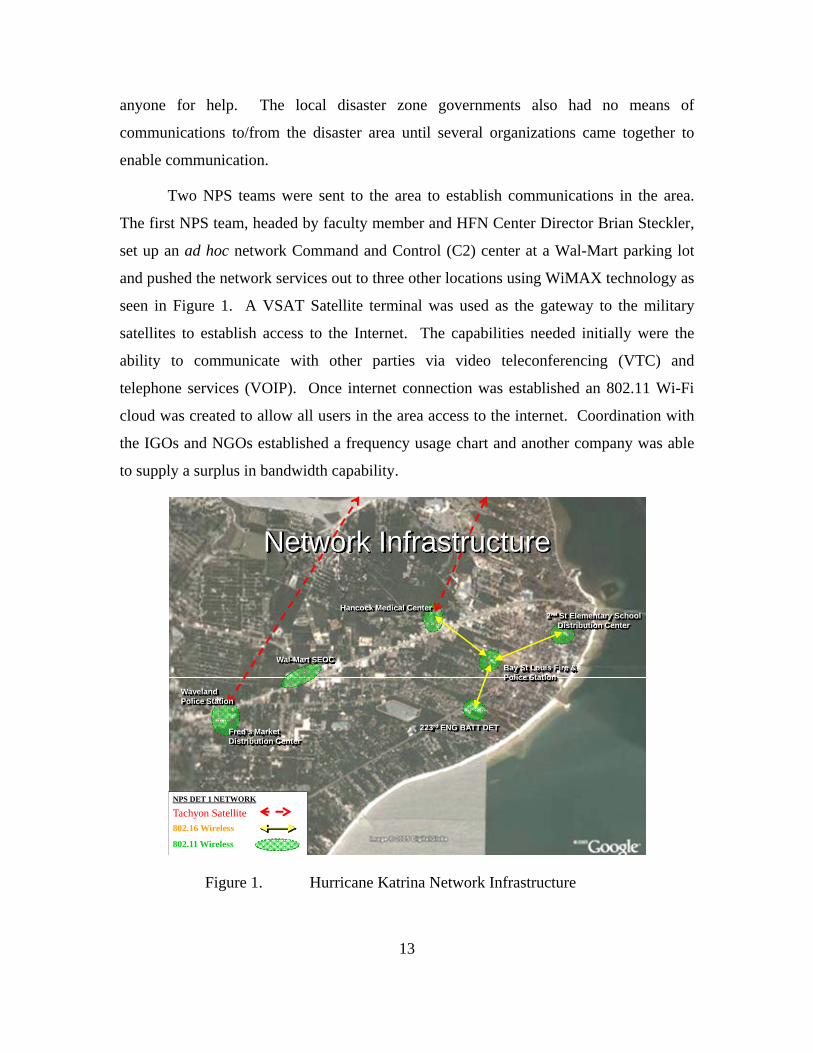
Two NPS teams were sent to the area to establish communications in the area.
The first NPS team, headed by faculty member and HFN Center Director Brian Steckler,
set up an ad hoc network Command and Control (C2) center at a Wal-Mart parking lot
and pushed the network services out to three other locations using WiMAX technology as
seen in Figure 1. A VSAT Satellite terminal was used as the gateway to the military
satellites to establish access to the Internet. The capabilities needed initially were the
ability to communicate with other parties via video teleconferencing (VTC) and
telephone services (VOIP). Once internet connection was established an 802.11 Wi-Fi
cloud was created to allow all users in the area access to the internet. Coordination with
the IGOs and NGOs established a frequency usage chart and another company was able
to supply a surplus in bandwidth capability.
Wal-Mart SEOC
Waveland Police Station
Fred’s MarketDistribution Center
Hancock Medical Center
Bay St Louis Fire & Police Station
2nd St Elementary SchoolDistribution Center
223rd ENG BATT DET
Tachyon Satellite802.16 Wireless
802.11 Wireless
NPS DET 1 NETWORK
Network Infrastructure
Figure 1. Hurricane Katrina Network Infrastructure

14
The second NPS team, headed by Dr. Alex Bordetsky, set up another network and
used Microsoft Groove as its primary communicative application software. This team
based its operations in Pascagoula, Mississippi, aboard the PCU-San Antonio (LPD-17)
as shown in Figure 2. The goals and achievements for this team were to support the
“Hancock Regional Medical Center; federal, state, and local ‘first responder,’ and
displaced civilians” (Steckler & Bordetsky, Joint Task Force Katrina Relief Effort Brief,
2005).
Areas of Operation
Figure 2. NPS Team Locations
The issues faced by the NPS teams during Hurricane Katrina were mostly with
the collaboration of efforts with the government and the NGOs and IGOs. The number of
organizations involved in the rescue efforts led to an abundance of satellite earth
terminals but lacked communication coordination. This thesis will not discuss the
relationships between the NGOs, IGOs, and our government, but will rather focus on how
to enhance C2 capabilities with virtualized technologies.

15
C. HAITI EARTHQUAKE
The Haiti Earthquake came suddenly and wrought havoc throughout the small
island, leaving it in disarray. The Haiti government was left in shambles and without any
means of communications due to the lack of technology. Many organizations instantly
came to the rescue providing relief for the survivors. An NPS crew led again by Brian
Steckler and the HFN Center was mobilized quickly and departed to Haiti to help in the
communications efforts. Upon arrival, it became clear that there had been little to no
communication between the government and the IGOs and NGOs on how to set up
communications. Each individual group in Haiti had its own VSAT or BGAN to
establish its own communications, but left the other groups out. This did not help the
Haiti government in its rescue efforts.
The NPS team took with them four BGAN units with Wi-Fi capabilities and a
SWE-DISH earth terminal for Internet connectivity. These devices were suitable
terminals for gateway access, but the cloud created would be difficult to manage. Also,
the ad hoc network that was set up would have the capability to connect to the Internet by
itself. Many other groups had this same capability but there was a lack of command and
control within the area of operations (AOR). Virtualization technology is a possible
solution to attain command and control and can also bring more capabilities to the area.
This thesis will further explore and discuss virtualization technologies in the next chapter.
Because of the many actors that had a role in the relief effort to provide aid to
Haiti, social networking was highly employed. This is the first instance that social media
had been used in this type of setting to aid in command and control. The strength of
social media in supporting an HFN is that information during these settings is found
through text messages, images, videos, blogs, etc., that are all forms of knowledge. The
empowerment from this knowledge, derived from its centralization, seemed more capable
in one setting, which turned out to be a form of social media. Decision makers are able to
make more informed decisions based on information gathered from social networks in the
disaster area. At the same time, information was sent out to friends and families about
the whereabouts of their loved ones to have the assurance of their safety. Social media fit

16
extremely well with the HFN environment because of its ability to adapt and change to
the needs of the responders (Yates & Paquette, 2010).

17
III. VIRTUALIZATION/CLOUD COMPUTING
A. BACKGROUND
Virtualization Technology is quickly revolutionizing the way we work with
computers and networks. Virtualization is defined as “the abstraction of one computing
resource from another computing resource” (Lowe, 2009). Virtualization is applicable to
all types of hardware and software applications and is used by single users, small
businesses, and enterprises. Through the use of virtualization, multiple operating systems
can be run on the same hardware. This technology can be pertinent to Hastily Formed
Networks (HFNs) because of its ability to deftly conform to the needs of the users.
The users of virtualization technology operate at the first (physical) and second
(data link) levels of the Open Systems Interconnection (OSI) model. The rest of the
levels of the OSI model carry content data. The system the users are operating, may use
layer one and two, but they are interacting with their system just like any other desktop
PC. The system will access the upper layers via the Internet or layer 3 of the OSI Model.
Figure 3. OSI Model from CCNA (From CCNA, 2011)

18
Hastily Formed Networks need the combination of several technologies and
applications to enhance command and control. The first on-site responders to disasters
need essential applications and access to the Internet along with databases to properly
establish a central command location. The HFNs key attribute is its ability to conform to
the surroundings and enhance command and control within a geographical area.
Virtualization technology allows for the first responders to bring minimal equipment
capable of hosting multiple operating systems and applications pertinent to the needs of
the users.
Commercial off-the-shelf (COTS) hardware brought to a disaster zone optimizes
the user experience when connecting to virtualized systems. Specifications are often
aimed at VMware among many other vendors to ensure compatibility with the
hypervisor. The hypervisor is a software program that acts as a supervisor of other
systems and allows multiple operating systems to run on a single host computer. COTS
devices called clients have reach-back capabilities that allow for greater speeds of
connectivity to databases through a point-to-point connection generated through a
gateway via the Internet. This is a form of virtualized technology that uses hardware to
access a regional cloud to tap into available resources.
Hardware can also be transported to certain locations with limited Internet
connectivity to forward deploy pertinent virtualized operating systems and software
applications with a first response team. This type of virtual system is not reliant on the
World Wide Web (WWW) to function correctly and can establish a connection to the
users within a specific area of operations (AOR). Both virtualized systems are specific to
their surroundings and must be used correctly to enhance overall command and control.
Virtualized technology is evolving to the point where thick hardware clients are
becoming obsolete with the advancement of software on platforms such as notebooks,
handhelds, and tablets that can be easily deployed with the users and that can easily
access the virtual clouds. This hardware can use software application such as VMware
Elastic Sky X Integrated (ESXi) to access a virtual system or partition a personal device
with multiple operating systems. The virtual technology sits between the physical server
and the operating system (Dell, 2011). With the virtualization concept housing the data

19
in the rear the system can be run on multiple servers allowing for redundancy, high
availability, distributed resource sharing, and fault tolerance. Below are a few devices
that can aid in the deployment of virtualization technology.
B. VIRTUAL DESKTOP INFRASTRUCTURE (VDI)
VDI is a virtual technology that centralizes operating systems and applications on
client machines that run on a hypervisor on a shared server. This architecture is designed
to reduce the reliance on the user’s computing environment and allows support staff to
fully aid clients in a virtual environment. The endpoint devices most commonly used are
“blade PCs, software clients, thin clients, and zero clients” (Panologic, 2010) that capture
the data and project it onto a screen.
Figure 4. Client-Server Architecture from Panologic (From Panologic, 2010)
Virtualization Technology first began in the 1990s with the thick client as its
primary hardware communications device. This device, when attached to a computer,
becomes a client in a client-server architecture. A thick client is a standalone device that
does not need to be connected to the network to function. It has the ability to process
information by itself when it is not connected to the network (Hewlett, 2008). The thick

20
client is ideal for a Hastily Formed Network should the Internet connection be lost. Also,
the thick client alleviates traffic to the server’s infrastructure because of its own
processing capability (Hewlett, 2008).
VMware decided to shift more of the processing burden onto the server, which led
to the creation of the thin client. The thin client is based on a client-server approach VDI
that allows the user to maintain functional and storage capabilities. The thin client is a
lightweight, portable device that can attach to any client device or monitor to work. The
thin client relies heavily on a server to function and is essentially a device that projects
the data received from the server onto a screen. It is ideal for speed and allows the users
to function as if they were using their computer from the home or office. In an HFN
setting, the thin clients would need to have access to necessary bandwidth to function
correctly. However, a thin client does have an embedded operation system such as Linux
or Microsoft XP® and limited processor, memory, and storage capabilities. This allows it
to run some applications locally should connectivity to the Internet become disrupted.
Thin clients also offer a security advantage by having write-protected disk drives. Should
a system become compromised, simply turning it off will remove whatever malware was
present, and the operating system (O/S) can be patched to prevent the breach occurring in
the future.

21
Figure 5. Thin client Architecture from Panologic (From Panologic, 2010)
Recently, the zero client has been produced to increase the speed of
communication between the client and the server. The zero client was developed by
Wyse in 2010 “which is like a thin client, but with less to manage and maintain on the
client device itself” (Madden, 2010). The zero client is designed so that the clients
device has no processing or management, thus increasing system speed. Further
performance gains are achieved by optimizing the communications protocol, and
VMware now utilizes a software known as PC-over-IP (PCoIP®), which was developed
by Teradici (Leibovici, 2010). This optimizes communications between the client and
server, particularly video performance, which is critical for improved end-user
experience.
The zero client requires a monitor or some device to display the image and is
centralized in functionality. It does not work with other operating sytems nor storage
devices on the users end to free up system speed, reduce complexity, and enhance
security. The speed is directly related to bandwidth and the speed of the server housing

22
the virtual operating system. The system becomes immediately hardened by zero clients
because of the lack of client side operating systems and the inability of users to use
storage devices. Storage devices such as flash drives or external hard drives have been
persistent problems in the past for many businesses in the civilian sector and the
government as a whole. These devices have the ability to load sensitive data onto a
small, easily transportable, albeit unauthorized device that, can easily leak out classified
information.
Figure 6. Zero client Architecture from Panologic (From Panologic, 2010)
The thick client data flow process and speed deterrence tends to appear like that
depicted in Figure 7. The user will use a computer or other PC device to access a
virtualized operating system from a server. The server will send the data back to the
computer for usage. The speed of the data flow is dependent upon the computer’s
processor, bandwidth used to access the server, and the server’s processor. If any of
these speed dependencies are functioning slowly for any reason the data flow will be
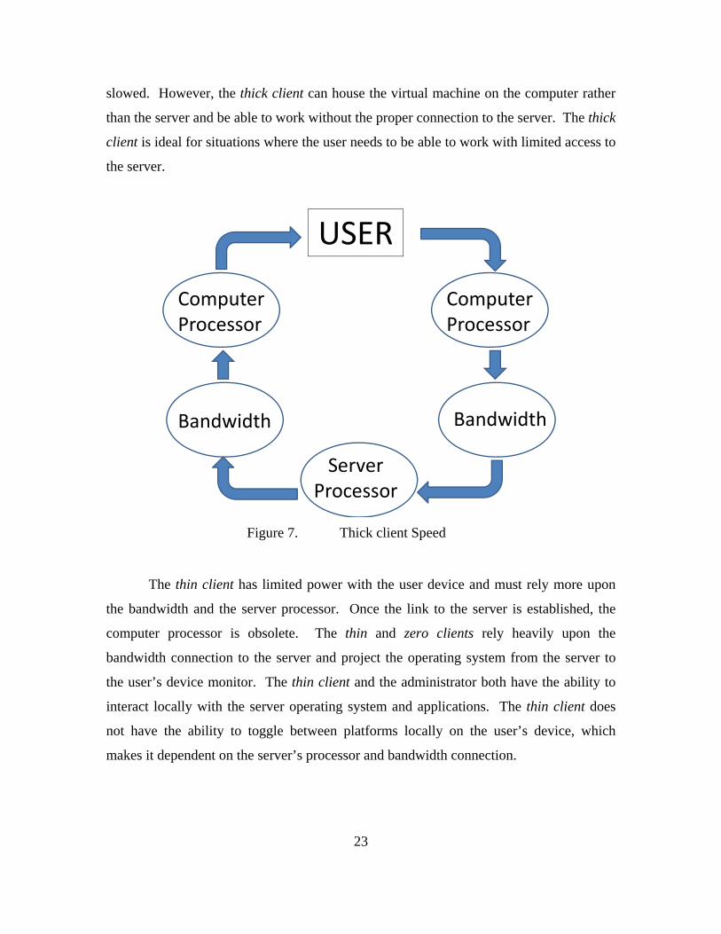
23
slowed. However, the thick client can house the virtual machine on the computer rather
than the server and be able to work without the proper connection to the server. The thick
client is ideal for situations where the user needs to be able to work with limited access to
the server.
USER
Computer Processor
Computer Processor
Server Processor
BandwidthBandwidth
Figure 7. Thick client Speed
The thin client has limited power with the user device and must rely more upon
the bandwidth and the server processor. Once the link to the server is established, the
computer processor is obsolete. The thin and zero clients rely heavily upon the
bandwidth connection to the server and project the operating system from the server to
the user’s device monitor. The thin client and the administrator both have the ability to
interact locally with the server operating system and applications. The thin client does
not have the ability to toggle between platforms locally on the user’s device, which
makes it dependent on the server’s processor and bandwidth connection.

24
USER
Computer Processor
Server Processor
Bandwidth
Figure 8. Thin client Speed Factors
The zero client has no computer processor power at the user end and must rely
solely upon the bandwidth and the server’s processor for the data flow optimum speed.
The zero client is simply a projection device of the operating system stored on the server.
The zero client data flow is depicted in Figure 9, which shows the lack of dependence on
local processors. However, the zero client must have a good bandwidth connection to
function properly.
USER
Server Processor Bandwidth
Figure 9. Zero client Speed Factors

25
C. CLOUD COMPUTING
Virtualization technology is at the heart of cloud computing. Cloud computing is
defined as “the ability to utilize scalable, distributed computing environments within the
confines of the Internet” (Kaufman, 2009). Cloud computing has evolved since the
1960s, when JCR Licklider introduced the concept at the Advanced Research Projects
Agency and coined the term as “intergalactic computer network” (Kaufman, 2009).
Since then, cloud computing has gradually evolved with an exponential growth in the
1990s when virtual private networks (VPN) were introduced into the cloud concept.
The cloud has not precisely been defined because of its evolving paradigm;
however, the United States National Institute of Standards and Technologies gives it
further definition stating, “Cloud computing is a model for enabling convenient, on-
demand network access to a shared pool of configurable computing resources that can be
rapidly provisioned and released with minimal management effort or service provider
interaction” (NIST, 2011). The cloud is a way to leverage resources for users in a simple
and manageable way as shown in Figure 10.
Figure 10. The Internet Cloud (From Alkima, 2011)
The “cloud” has often been used as a metaphor for the Internet. If the Internet can
be a cloud than nodes that are connected to the Internet cloud can be considered clouds

26
within the Internet cloud. This research identifies two different clouds, the regional cloud
that would be considered a subset of the Internet cloud because the only access to it is
through a point-to-point portal via the Internet, and a local cloud, created specifically for
a locality, which would have limited access to the Internet cloud. Regardless of the
cloud, all clouds are inherently based on a virtual infrastructure. After building the cloud
base, the architecture can be applied and ultimately a dynamic cloud that is self-serving,
application sharing, and has the ability to self serve is created as shown in Figure 11 of
Amazon’s Cloud Computing Adaptation Model.
Figure 11. Cloud Computing Pyramid Architecture from Amazon (From Edge, 2011)
Both the regional and local clouds created consist of a server platform that is able
to service multiple operating systems depending on their capacity. Naturally the regional
cloud would be more robust and have more capabilities than the local cloud. The
regional cloud would need substantial bandwidth through the Internet to function
appropriately. On the other hand, the local cloud is self-supportive and would need
limited or no access to the Internet cloud because of the ability to support local databases.
Figure 12 depicts the basic hardware needed to create a cloud and what the infrastructure
might look like.

27
Figure 12. Cloud Computing Basic Architecture (From Rajasekar, 2011)

28
THIS PAGE INTENTIONALLY LEFT BLANK

29
IV. HASTILY FORMED NETWORKS
A. BACKGROUND
Hastily Formed Networks (HFNs) are used to create nodes in areas where there is
currently no network connectivity. HFNs act as an extension of the enterprise network to
facilitate aid to Humanitarian Assistance/Disaster Relief (HA/DR) missions. These
missions must be flexible in nature because they are unpredictable and the HFN team
must be ready to depart to the area with little notice. The HFN node must have “reach-
back” capabilities, which is the ability to obtain products, services, and applications that
are not forward deployed. The Department of Defense (DoD), in particular, has a vested
interest in the “reach-back” capabilities of the HFN for data from the enterprise databases
to be readily available to the first responders. This thesis will discuss briefly later in this
chapter the flexible nature of the Hastily Formed Network in relation to the Enterprise,
the best architectural fit for a HFN along with the impact of virtualization on the system,
and the data flow between the HFN and the Enterprise network.
The architecture of a typical HFN with data capabilities usually consists of an
internal network and a portal to the Internet. Usually for the internal network there is a
switch that will direct the flow of data in the internal network. Often, there will be a
wireless port that is set up for users to access the network wirelessly. WiMAX terminals
may be used to connect to other nodes of the branched network. The setup will have at
least one portal that links to the satellite. The portal is also called the gateway and will
transmit data from the external network to the internal network.
Virtualization technology can aid in the reach-back capabilities of the HFN and
the components could easily be added to the Rapid Response Kit (RRK) of a first
responder. The RRK is the gear initially taken with a first responder to a disaster area.
Ideally, the RRK would have the capabilities associated with an internal virtual hastily
formed network supported by a regional cloud for reach-back capabilities. The
bandwidth needed to properly maintain a point-to-point conduit for reach-back to a
database would be difficult. However, with virtualization technology, the bandwidth

30
needed for reach-back capabilities should be less. The reason for less bandwidth being
needed with virtualization technology is that only selected individuals that need
information from the enterprise would be allowed the reach-back capability. The HFN
can also use a portal to VPN into the Marine Corps enterprise network. Virtualization
technology can also be taken advantage of by taking the virtual system to the HA/DR
area to set up a local cloud that can be accessed within a defined area by several
individuals. Consequently, the network manager would be better capable of controlling
the flow of traffic through the gateway.
The virtual HFN is smart and dynamic in nature and has the ability to provide
services to many more users because of lower bandwidth utilization along with a smaller
footprint. To apply the virtual concept to the HFN, a server along with a storage device
with redundant capability will be needed to back up all the data for the system. This is
the most ideal virtual system for the initial stages of an HA/DR mission that has little to
no infrastructure already set up. For example, when a team flies into a natural disaster or
humanitarian relief area, they will set up the virtual system in a systematic method.
The initial setup of the virtual system will begin with the gateway terminal, which
will establish a link with the satellite. Once the link has been established, the gateway
terminal will then request access to the Internet by using IP address configuration with
the host satellite. This setup can also be accomplished in parallel, not in series. This
reduces total set-up time and gets the system working sooner. Once the flow of data
begins to enter the system, then the internal virtual network can be established. The data
will go from the gateway to a switch and then to a server that will be the host for the
virtual application for all end users. The server will then send the applications to the
switch, which will determine where the data goes next. The data will either go to the
wireless 802.11 port or to a hub or switch that the user’s computers can be connected to
via 802.3. The users will send a request to the server to use the virtual applications on
their computers via a software broker. In VMware, this is known as a connection broker.
The virtual setup can create an ordered environment for a HA/DR mission
initially. The setup can also enhance capabilities of end users, leave a smaller footprint,
and require less equipment. All the data that is used for this setup will be stored in a
31
memory bank such as a Network Attached Storage (NAS) device or something similar
and light weight. Solid state hard drives could be used, as they require less power and
have no moving parts, which improves their survivability in a mobile environment and
has the added benefit of much higher performance than traditional spindle drives.
Applying this methodology to a hypothetical real world situation helps to
understand the complexity of a virtual HFN. By placing it in an environment that is
representative of a disaster area aids in understanding the impact of virtualization
technology in this scenario. For example, if a category 5 hurricane reaches the city of
Miami then the resultant floods would have destroyed all communications lines and any
infrastructure in the area. In this example, a team would be dispatched with the HFN
equipment and makes the base camp at the airport. The team establishes a link to the
satellite within 30 minutes with a Very Small Aperture Terminal (VSAT) such as a
Tachyon or Cheetah earth terminal. The IP addresses are input into the terminal and the
team establishes connectivity with the World Wide Web (WWW). The internal network
set-up begins by connecting the server, switch, 802.11 wireless port, and as many 802.3
connections as needed for the end nodes that have been brought down with the team.
Once the equipment has been set up, the users will then begin to access
applications from the virtualized server operating systems application servers. These
applications will be preloaded onto the virtualized desktop operating system of each
virtual desktop so as to fit the needs of the mission. Applications such as Skype, Google
+, and other programs will use less bandwidth because of the virtual architecture and will
be less likely to cause a bottleneck in the system. This scenario depicts what could occur
if a virtual HFN were used during HA/DR missions.
B. HFN BUSINESS ARCHITECTURE
The business architecture needs to be defined for the need of an HFN along with
the integration and standardization of this network. Currently, the HFN has issues with
disseminating information to remote areas. Many mobile to base-station to mobile or
mobile to mobile routing technologies are used with little utilization of mesh routing.
The only gateway to the Internet is through satellites in most scenarios, however, in some

32
cases, occurring with more developed countries such as the Japan earthquake and
tsunami, the present gateway infrastructure was intact and usable.
The business processes and functions are needed to understand the HFN system
architecture and can be defined through agility and environmental turbulence. Agility
and flexibility, in a business technology setting, are often used interchangeably and can
define the timeframe of a business process along with the ability of the system to adapt to
its surrounding. The range agility is the ability of the business process to mature
depending on the functions of the system along with the overall cost. The time agility is
the speed it takes for the system to develop and is directly related to the environmental
turbulence. The range agility of the HFN is low because processes and functions are the
same for each mission. The environmental turbulence for the enterprise is high due to the
ever autonomous nature of the business environment. Lastly, time agility for the HFN as
an enterprise is high due to the time required to adapt to new missions. According to the
agility matrix (see Table 1), the HFN falls into cell 2. This matrix informs the reader that
the current architecture for HFN is a good fit overall (Sengupta, 2011).
Table 1. Agility Logic Matrix Considering Range, Time and Environmental Turbulence (From Sengupta, 2011)

33
In Table 2, the HFN architecture has high Business Process Integration (BPI) and
low Business Process Standardization (BPS). The HFN is able to adapt to new
environments and is able to reach all the users such as DoD agents, NGOs, IGOs and
adapt to their needs by providing specialized services. Due to the specialized services the
HFN has high integration with other entities to accomplish its mission. If the HFN was
standardized it would not have the flexibility to adapt to new and challenging situations
and environments such as dealing with the network policies of other countries.
Table 2. Four Logics for Enterprise Architecture (From Ross, Weill, & Robertson, 2006)
In review, the architecture for the HFN relies heavily on the entire enterprise
system. Once the HFN is established in an HA/DR mission it must have reach-back
capabilities to tap into services and databases that are run at the enterprise level.
However, due to the flexibility of the HFN, it is able to adapt and overcome difficult
situations and environments as seen by the virtualization concept.

34
C. MANPACK
1. Flyaway Kit
The flyaway kit (FLAK) is a rapidly deployable communications package, or
backpack, capable of establishing communications quickly in any environment. This
case can be altered to fit the needs of the team or the environment. However, the
essential equipment covers the areas of satellite connection, network meshing, energy
requirements, and handheld communications. These four areas are essential in
establishing a first response communications network capable of supporting a small team.
The satellite earth terminals are the primary means of creating a gateway to the
Internet. The satellite terminals can be categorized in two different categories, BGAN
and VSAT, both of which will be discussed later in this chapter. The parabolic aperture
of a satellite earth terminal will range in various sizes to maximize gain and efficiency
while minimizing packet loss. The most important aspect of the terminal for first
responders is the size and weight to bring it into theater. The data link established will
vary depending upon the earth terminal but means of transportation is the most critical.
Network meshing can allow the first responders to expand their network to other
areas. This can be done using Redline or similar WiMAX devices that create a wireless
bridge several miles from a Master device to a Slave device. In May 2011, while at
NASA Ames Research Center, the NPS HFN team with CISCO to create a meshed
Network, which is a combination and integration of several wireless technologies. This
was done using the Network Emergency Response Vehicle (NERV) from CISCO and the
WiMAX devices from NPS. The NERV was used to establish satellite communications
through their gateway earth terminal. The WiMAX devices were then linked to the
NERV and transmitted a Wi-Fi signal to other locations. The WiMAX device relies
heavily on line of sight and objects such as buildings and trees can hinder the signal. The
team was able to transmit the signal to a gas station approximately a half mile away and
relayed the signal to a trailer set up in a parking lot across an airfield about three miles
away. With little data loss the trailer used the signal to create a Wi-Fi cloud around the
trailer for any users to access.

35
Figure 13. CISCO Network Emergency Response Vehicle (NERV) (From MCNC, 2009)
During this exercise, the team was able to use CISCO VOIP phones through the
802.11 signal to establish video conferencing. CISCO also used VOIP phones that
directly connected to the Internet through the Wi-Fi signal and operated exactly like a
normal cell phone. A smaller vehicle, called the Lexus Emergency Response Vehicle
(LERV), was created by mounting a mobile BGAN earth terminal on top of a Lexus
sedan. The LERV was used for on-the-go video teleconferencing (VTC) along with
relaying video footage of the surroundings around the vehicle. This type of capability
could be ideal for command and control during disasters to help everyone get better
situational awareness of the desolation that might have occurred.
36
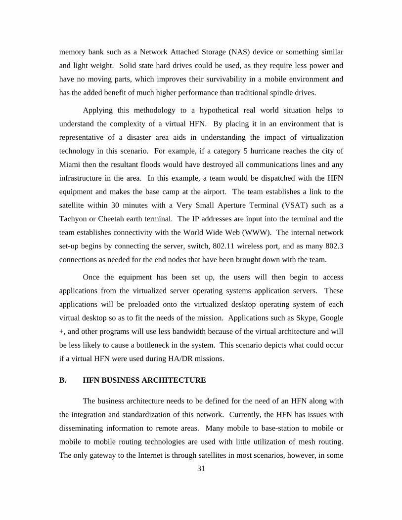
Figure 14. Fly Away Kit (From Steckler & Meyer, 2010)
2. Virtual Flyaway Kit (FLAK)
The virtual flyaway kit consists of two cases—a small server rack case and a case
that would hold clients, cables, and monitors. This small package would be able to
support all the clients brought to the disaster along with any other users that would like to
use their personal computing device. For users to connect to the virtual cloud, a
VMSphere download would be required (freeware downloadable from the Internet). A
simple rack that could support virtual technology would consist of a server, modem, and

37
a laptop as depicted by Figure 15. This particular virtual flyaway kit, currently being
built at NPS in the Virtual/Cloud Computing Lab, is easily transportable by two people.
Figure 15. Virtual Flyaway Kit
D. NETWORK
1. Network Operating Center (NOC)
The Network Operating Center (NOC) is the central location for all
communications established. During the Katrina and Haiti disasters the NOC was slow
to be established due to the many first responders attempting to communicate, along with
the slow response from the government officials. The NOC is typically managed by a
network managing system, which is software that can monitor the system and alert the
users of any issues. Typical network managing systems include software such as

38
DopplerVUE, which is created by Kratos Network and SolarWinds. Through these
programs, the users can establish Management Information Bases (MIBs) and monitor
performance metrics such as bandwidth, capacity, speed, and throughput. Figure 16 is a
screen shot, taken at the NPS Virtualization/Cloud Computing Lab, of the ability of
DopplerVUE to isolate a single node on the network and monitor it. This monitoring
allows for the network to minimize bandwidth usage and ensure network access and
enhanced capabilities to various users.
Figure 16. DopplerVUE Screen Shot
During the studies at Avon Park, Florida, the team the author was part of used
DopplerVUE and SolarWinds to identify, monitor, and manage the network utilizing the
1213 MIB. There can be issues with loading the software onto the laptop; however, after
a little time and assistance from the Kratos help desk, it should operate correctly. The

39
team fortunately had a version of SolarWinds already installed. Management of the
network utilizing two different nodes with two different software platforms proved to be
challenging.
DopplerVUE was difficult to configure due to lack of knowledge and low experience
levels. Once familiarized, the range of IP addresses was entered into the discovery tool
allowing it to discover all the devices connected to the network. DopplerVUE was leveraged
to access remote devices, monitor bandwidth utilization and view other pertinent information
available via Simple Network Management Protocol (SNMP).
When using the SolarWinds network management software, the team performed
network discovery and monitored the network for degradation and outages. To perform
a network discovery, the applications from discovery tools from both SolarWinds and
DopplerVUE were used. The IP Network Browser function on SolarWinds was used to
scan for all IP addresses being used within the subnet address of 192.168.87.0 and subnet
mask of 255.255.255.0. In this case, the team found that only two of all IP addresses
being used identified equipment capable of supporting SNMP information capture (MIB
1213). Figure 17 indicates the SNMP IP Addresses and System Name of the SNMP
capable equipment by a plus sign (+) prior to the IP Address. Selecting the plus sign (+)
expands the selection to observe greater detail of the item.
Figure 17. SolarWinds IP Network Browser
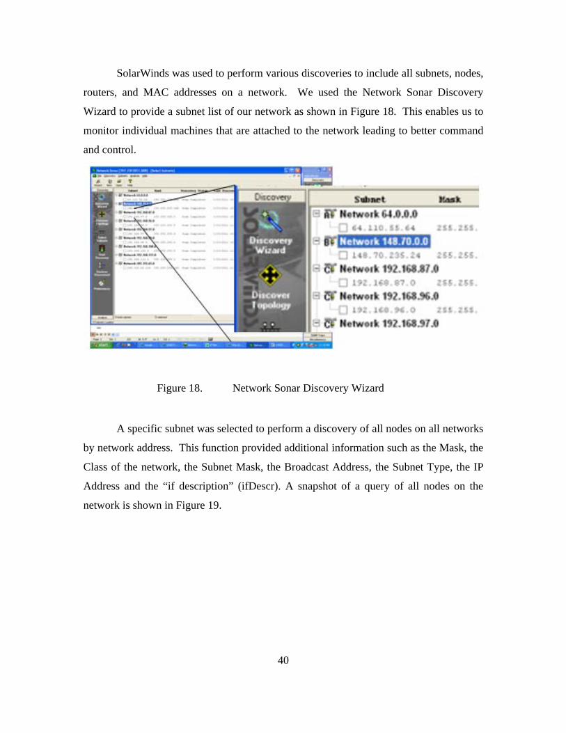
40
SolarWinds was used to perform various discoveries to include all subnets, nodes,
routers, and MAC addresses on a network. We used the Network Sonar Discovery
Wizard to provide a subnet list of our network as shown in Figure 18. This enables us to
monitor individual machines that are attached to the network leading to better command
and control.
Figure 18. Network Sonar Discovery Wizard
A specific subnet was selected to perform a discovery of all nodes on all networks
by network address. This function provided additional information such as the Mask, the
Class of the network, the Subnet Mask, the Broadcast Address, the Subnet Type, the IP
Address and the “if description” (ifDescr). A snapshot of a query of all nodes on the
network is shown in Figure 19.

41
Figure 19. SolarWinds Subnet Query
The SNMP Sweep function of Network Sonar tool lets the network manager
select a range of IP Addresses to be scanned. Routers were identified using the Router
Query and used the MAC Addresses Discovery tool to identify additional equipment such
as switches and Virtual Private Networks on the network. Both queries provided detailed
information about the queried items to include key elements such as Agent IP Addresses,
DNS, Response Times, System Descriptions, Physical Addresses and IP Addresses, as
shown in the Router and MAC Address Query snapshots in Figure 20.
Figure 20. SolarWinds Network Sonar Tool

42
The SolarWinds chart function of the Network Sonar tool was used to determine
the make-up of the network. This function provided several views to include the
Machine Types, Nodes by Network, the Interface Types and the Subnet Types shown in
Figure 21. Each chart provided greater insight as to the composition and support
requirements of the network.
Figure 21. SolarWinds Chart Function of Network Sonar Tool
The Network Performance Monitor was used during the research to observe the
up/down status of nodes, with special interest in monitoring the Domain Name Server
(DNS) nodes, the Virtual Private Network (VPN) node and the Default Gateway. The
data shown in Figure 22 was collected at a time when the network had just recovered
from a “hit”, or degradation, where the network experienced an approximate 20% packet
loss at the Default Gateway. The Default Gateway (64.110.55.65) has an “up” status

43
(shown as bars at top of graph) yet some nodes are still “down” (shown as line at bottom
of graph) while the network is going through the recovery stage.
Figure 22. SolarWinds Network Performance Monitor
In addition to the monitoring of the network, the Avon Park Team monitored an
NPS Resource Portal called “CENETIX” that contained applications such as the
Observer Notepad, Stream Video Monitor, as shown by the data snapshots taken during
the exercise as shown in Figure 23.

44
Figure 23. Video and Observer Notepad
In addition, the Team monitored the Video Conferencing tool, the SA Web Agent
Control, and Google Earth SA Viewer. During the Battle Field Medical segment of the
exercise, the Avon Park Team monitored the Avon Park network and VPN connection
while simultaneously monitoring the Stream Video Monitor connection with NPS TOC,
the BF Medical Exercise at Camp Roberts and Salinas Medical facility, and BF Medic
Console, which provided detailed position information and video feeds to and from Camp
Roberts and the Salinas Medical facility casualty room, as shown in Figure 24.

45
Figure 24. Battle Field Medical Experiment
2. Ad hoc Network
An ad hoc network is composed of several nodes that are set up wirelessly to
form a temporary network (Maltz, 1999). This network is not established from an
existing network nor is there any established centralized administration. Nodes are
entities attached to the network outside of the NOC and have the same capabilities as the
NOC. The nodes are a means to push the network to other locations and further enhance
communications within a specified AOR. In an ad hoc network, the nodes are linked
together to exchange information enabling the users to communicate with other networks,
databases, and users. The nodes are important because they allow the specified area to
become enhanced in various capabilities. As discussed in Chapter II, an example of an
ad hoc networking infrastructure is displayed in the Hurricane Katrina case study where
they established the NOC and created nodes around the central location. Pertinent
information was passed between the locations along with access to outside entities via the
Internet.
Improving the speed of the connection between the nodes can be done by
Dynamic Source Routing (DSR) protocol, which uses specific routes to control the

46
pathway of the packets through the network. The intermediate nodes of the network can
be influenced by two different kinds of soft-state, namely path-state and flow-state. The
path-state “allows intermediate nodes to forward packets according to a predetermined
source route” while the flow-state “allows a source to differentiate its traffic into flows,
and to then request better-than-best-effort handling these flows” (Maltz, 1999). Both of
these states together help to manage the ad hoc network along with increasing the speed
of the data transfer between nodes.
The least expensive and current means studied for this thesis was through the
interconnection of nodes via WiMAX bridges. This requires a direct line of site from
location to location to link the terminals and transfer data. The WiMAX terminals create
an Ethernet bridge across the area to form this connection. This connection is ideal for a
virtual technological setting to maximize the server usage of the virtual operating systems
while decreasing bandwidth to the satellite.
E. SATELLITE GATEWAYS
1. BGAN
The Broadband Global Area Network (BGAN) was created in 2006 and was
designed to be transported by a single person and able to connect to a satellite within
minutes. It is an ideal solution for a first response team because of its light weight, speed,
and ease of use. The BGAN is ruggedized and some models such as the Hughes 9201
and Thrane/Thrane 700 also come with the ability to broadcast a Wi-Fi signal within a
100 meter circumference area. An additional feature the BGAN has is its ability to
designate the speed of the connection when first synchronized to the satellite which can
be seen as both an advantage and a disadvantage. The user does not necessarily get the
best speed all the time but the user will know the exact speed of the BGAN connection.
The BGAN does have some drawbacks and limitations. First, it is required to run
on Subscriber Identity Module (SIM) cards. The SIM cards are only good for a
designated amount of download bandwidth and can be used up quickly creating a need to
carry multiple SIM cards each time the BGAN is used. Second, the cost to use the device

47
is much greater than the VSAT because it is based on data usage versus flat monthly fees.
Lastly, the BGAN relies heavily upon Line of Sight (LOS) to the satellite and when
deployed in metropolitan areas with big buildings or in mountainous areas with large
mountains or large trees it can be difficult to establish and maintain connections.
Because the BGAN is limited in bandwidth (256 ~ 400 kbps), it is not the most
ideal gateway for reach-back capabilities using virtual technology. However, this
research explores all avenues of approach toward maximizing virtual technology with all
HFN systems and the conclusion of the BGAN test with virtual technology is found in
Chapter VI. Currently, the BGANs per megabyte usage model, is not ideal for a virtual
setting that requires reach-back capabilities and a steady stream data transfer to work.
However, if the virtual system was located onsite, it would drastically limit the need for
bandwidth to the Internet and would work well with a BGAN. The measurements for the
BGAN will be discussed in the next chapter.
2. VSATs
Very Small Aperture Satellite Terminals (VSATs) differ in size and weight but
can handle several types of different bands (X, C, Ka, and Ku) and can connect to an
array of satellites. The VSATs are typically built with ease of use and portability in
mind. Although it is neither as small nor user-friendly as the BGAN, it is simple in
nature to connect to a satellite to establish the gateway for the link to the Internet. The
BGAN requires the user to establish a connection to another terminal or agency that
operates the respective satellite. The connection requirements are found via two forms
called the Satellite Access Request (SAR) and Gateway Access Request (GAR) that
identifies the IP codes and any other pertinent information needed for the gateway. The
measurements for a few VSATs will be discussed in the next chapter.
48
THIS PAGE INTENTIONALLY LEFT BLANK

49
V. SATELLITE MEASUREMENTS/REQUIREMENTS
A. BGAN MEASUREMENTS
Figure 25. Hughes 9201 BGAN
The BGAN used during our testing was the Hughes 9201, which is a lightweight
portable device that has Wi-Fi capabilities once connection is established. This particular
device can be carried in a shoulder bag or briefcase. The BGAN has the capability of
transmitting data at an uplink speed of 492 kbps and downlink speed of 492 kbps
(INMARSAT, 2011). However, this speed can only be reached with the X-stream
capability. On connections with the satellites, the user must specify the connection speed
of 32, 64, 128, 256 kbps, or X-stream. Once connected and the link has been established,
multiple users can use the device via the built in Wi-Fi access point.

50
Figure 26. BGAN Launchpad Connection Speeds
To establish the connection, BGAN has free software called Launchpad that you
can be downloaded via the BGAN website. The software is user friendly, can find the
BGAN quickly, and has step-by-step instructions to connect to the satellite and begin
streaming data. However, during our tests we found that Inmarsat created a new version
of Launchpad software that has more specifications and was not as user friendly.
Because of the difficulty of the new software, we reverted back to the original Launchpad
program to establish the connection.

51
Figure 27. BGAN Launchpad
While testing the Hughes BGAN at Kings Canyon in the Sierra Nevadas, the
BGAN registered a speed of 28kbps downlink and 18 kbps uplink using the established
256 kbps connection. The best signal strength to the satellites was 75% due to the high
canyon walls and large redwood trees. The huge data loss was unexpected and could be
due to the satellite connection. Also, a virtual connection was not able to be obtained on
the BGAN terminal.
During a separate test on the roof of Glasgow Hall at NPS, the same BGANs
registered uplink speed was on average 48 kbps and downlink was 32 kbps. The highest
uplink speed obtained was 79 kbps and the fastest download link was 54 kbps. The
signal strength to the satellite was 100% and the speed chosen was 256 kbps for each of
the speed tests. The weather was clear with little to no physical interference present.

52
Figure 28. Hughes BGAN Speed Test using speedtest.net
During testing an error message would come up on the BGAN software when
establishing a VPN connection. At first, the author thought this indicated that the service
would go down and the BGAN would not support virtual technology. However, after
further research and testing of the device, the BGAN would still function normally except
that it would cancel the BGAN software and close the connection to have a secure point-
to-point connection. Good security is ideal for reach-back capabilities because it will
prevent hackers from attaining sensitive information. The BGAN has the ability to
secure a channel to prevent potential hackers from gaining access to important or
sensitive data. The information assurance provided by the BGAN is superb for times
when the user needs reach-back capability to access data.

53
B. VSAT–TACHYON EARTH TERMINAL MEASUREMENTS
Figure 29. Tachyon Earth Terminal
The tachyon earth terminal is supplied by a commercial provider to the Internet
and can be deployed relatively easily. Tachyon prides itself on the user-friendly services
and top notch service support. The setup is accomplished by connecting the power
supply along with a data cable to the earth terminal. The earth terminal has a GPS
enabled satellite tracker and will automatically locate a satellite once powered up.
Tachyon Corporation supplies an application called InWiz that the user follows step-by-
step to set up the gateway terminal to the Internet.
For this thesis research, a .95 m tachyon earth terminal on the roof of Glasgow
Hall located on the campus of NPS. The particular tachyon earth terminal used was the
Tachyon Networks Vehicle Mounted Auto Deploy System. This vehicle mounted earth
terminal is ideal for Hastily Formed Networks because of its portability, mobility, and
transmission capability download speed of 1.544 Mbps and an upload speed of 512 kbps.
The average downlink speed obtained from the Tachyon earth terminal during our
research was 1.34 Mbps and the uplink speed was .2 Mbps.
The Tachyon earth terminal was found to be optimal for research purposes so it
was used on two different occasions about a month apart but at the same location. The
first time the tachyon earth terminal was used the entire set-up took 20 minutes to

54
complete. The second time the Tachyon earth terminal was used it automatically linked
to the satellite and set up the Internet gateway instantly. After simply providing electrical
power, it stored the pre-configuration from the first setup. The second setup architecture
included a thin client to simulate a regional cloud setting. The thin client was able to
establish a VPN connection to the NPS campus quickly. Using VMsphere, logging onto
a virtual operating system running from the server at the virtualization cloud computing
lab was instantaneous.
The connection had a lot of latency and after a diagnostic test a bottleneck was
found in the connection between the terminal and the satellite. This was to be expected
due to the amount of bandwidth provided, which only can be alleviated by a larger
transmitter capable of handling greater speeds. For our purposes, a small VSAT proved
to be ideal for a Virtual HFN setting. A larger VSAT would be unfeasible and too
cumbersome to take into a disaster area explaining why a small VSAT was primarily
used in this research.
After setting up link to the Virtualization/Cloud Computing lab we found some
latency. This was to be expected because satellite terminal connections typically
experience latency because of the distance it takes for the signal to travel. We performed
a trace-route to figure out the source of the latency. A trace-route is a diagnostic check
to see the pathway of the data to get from point of origin to the point of destination. It
lists all the routers the data passes through until its final destination and each leg from
router to router is called a hop. A trace-route is performed on the command prompt and
can identify the pathway of the data packets and the associated hops which are the time it
takes for the data packets to get from one device to the next.

55
Figure 30. Trace-route of Tachyon connection

56
This particular trace-route took a total of sixteen hops to get to the final
destination, which was the Virtualization/Cloud Computing Lab at NPS. During the
trace-route, the first hop was the Internet gateway, which was the Tachyon Incorporated
network. The Internet Service Provider (ISP) is found at the end of line one, which is
tachyon.net. Lines 2 through 4 are in the Tachyon network. Lines 5 through 8 are
routers on the att.net, which is a telecom supplier in the USA. Lines 9 through 15 are
part of the cenic.net, which is the Corporation for Education Network Initiatives in
California. Line 16 is the VPN portal access to NPS and allows access to the NPS
internal network. This is the final destination for the trace-route, yet if allowed to
continue through a normal route, rather than a VPN, it would show that the data was then
received by the NPS internal network, along with any internal routers and the servers
located in the Virtualization/Cloud Computing Lab.
Each of the first three columns is the response from the routers and the time it
took to ping three times measured in milliseconds. During the trace-route, the greatest
amount of time spent during a hop was the initial hop, which was most likely through the
satellite earth terminal. It is the initial gateway link that takes the longest time for the
data to go through. Once connected to the ISP and the telecom supplier the data was
much faster and the amount of time between hops decreased significantly. Fortunately,
for testing purposes, the trace-route did not time out which means all the hops were
working and all hosts were reachable.

57
C. CHEETAH MEASUREMENTS
Figure 31. Cheetah Earth Terminal
The Cheetah earth terminal is classified as a VSAT and is compact enough to fit
into two suitcases, also called a flyaway kit. The Cheetah’s components include: a fully
auto-acquire .9M elliptical antenna system, embedded iDirect iConnex modem, 25W
controller/processor and Ethernet switch, and ViewSAT software that provides a GUI
interface to monitor and control the terminal.
The Cheetah earth terminal was tested at Avon Park, Florida in February 2011
while providing support for a Department of Defense (DoD) exercise. It was used as the
backbone to the Tachyon earth terminal and used to support the Command Center users
directly. This VSAT is primarily used by the DoD and was easy to set up. It came with a

58
GPS auto tracking device already installed and had connection to a satellite within a few
minutes of starting. The Cheetah comes in several different sizes along with the
capabilities to use different bands depending on the needs of the users. The Cheetah
earth terminal used in this thesis research was specific to the Ku-band. The Cheetah
comes in two different sizes, basically, one earth terminal that has Ku-band link
capability, and a more robust earth terminal that can link to Ku-band, Ka band, and X-
band. Figure 32 illustrates the setup used in the research with the Cheetah earth terminal.
Figure 32. Diagram of Connection from Florida to NPS
During the exercise in Avon Park, the author worked with two other students in
building and maintaining the network. Before and during the exercise, the team worked
with CAPROCK Corporation, a satellite company that provides access to the Internet,
and MCTSSA, a subsection of the USMC that is responsible for testing new technology.
CAPROCK and MCTSSA were very willing to support our needs and flexible with our
changing test schedule. L-3 Corporations who works directly with SOCOM was gracious
enough to lend us their Ku-band Cheetah earth terminal.
Upon arriving to Avon Park, the team helped to set up the Cheetah earth terminal
and had full connectivity to CAPROCK within 30 minutes. The Cheetah earth terminal

59
is completely automated after assembly and because of its GPS capability it was able to
automatically find and auto-track the satellites. There were no complaints with the
Cheetah as it worked flawlessly.
On our first day, the team coordinated with (SATCOM) support to establish VPN
connection for the physical layer of the extended TNT Network at Avon Park, FL. The
Cheetah earth terminal OPT file was used to identify the Default Gateway, the Primary
and Alternate Domain Name Servers, the Subnet Mask, and the Group of IPs available,
as indicated in the Internet Protocol (TCP/IP) Properties as shown in Figure 33.
Unfortunately, the Default Gateway IP Address was incorrect and troubleshooting was
required to properly configure the Default Gateway.
Figure 33. IP Configuration Troubleshooting
The internal network was set up with two services being provided and working
together. The onsite setup had two different satellite earth terminals: Cheetah and
Wintec. The Wintec was used to provide the primary internet access to the clients. The
Cheetah was used to support the virtual link directly to the TNT and CENETIX lab. The
computers linked to the VPN network from the NOC would be using the Cheetah satellite
and all other clients external to the NOC would be using the Wintec. Figure 34 details
the internal network setup. The Wintec earth terminal was not used in this thesis
research.
Original Settings Based on OPT file Successful Connection Properties Incorrect Settings (Default Gateway Values believed correct)

60
CAPROCK
Cheetah Wintec
Switch 192.168.87.2 /24
Switch 192.168.97.2 /24
802.11 (TNT)
CISCO 2621 (routes b/t 87.x, 97.x, and out to VPN and Internet)
VLAN 87VLAN 97
Wave Relay (on roof)
VPN to CENETIX
Inet Port
USERS
USERS
USERS
Figure 34. Typical Hastily Formed Network Architecture
A secured connection was formed from Avon Park to Naval Postgraduate School
through the use of a point-to-point connection and VPN. The VPN protocol used to
facilitate security was IPSEC and ESP. These protocols allow for a TCP/UDP
connection to be established. Access to the Virtualization/Cloud Computing Lab was
established once connected to the NPS internal network. The team at Avon Park was
able to tap into the Virtualization/Cloud Computing lab and its resources, as shown in
Figure 35.

61
Figure 35. Connection Between Avon Park, FL and NPS
D. AN-TSC 168 MEASUREMENTS
Figure 36. AN-TSC 168
The AN-TSC 168 is a large VSAT earth terminal built by L3 Communications
and primarily used by the United States Air Force. The Air Force is slowly
decommissioning these VSATs and NPS obtained two surplus units for further research
in communications. The terminal is bundled within 23 large cases that hold the earth

62
terminal along with all the necessary equipment to run a network. The earth terminal is
meant to be set up by a team of workers because of the many parts and the heavy lifting
needed to assemble the earth terminal.
The AN-TSC 168 modems are capable of transmitting data from 9.6 kbps to 20
Mbps. It has the ability to provide critical link stability using C-band, X-band, Ku-band,
and Ka-band frequencies. The antenna control unit (ACU) is compatible with the
LHGXA, QRSA, and the AN/USC-60A subsystems. This terminal has the ability to
operate in a dual or independent hub configuration.
The NPS HFN team received an AN-TSC 168 unit for research purposes. No
testing was done on the unit for this thesis. However, the unit will be operational in the
near future and will be a primary means for gathering data for research conducted on the
campus. It can also be used to enhance the capabilities for NPS Information Technology
and Communications Services (ITACS) along with supporting the local community
during natural disasters.

63
VI. ENHANCED VIRTUAL TECHNOLOGY
A. LOCAL CLOUD CAPABILITY
HFNs are used to create nodes in areas where there is currently no network
connectivity. HFNs act as an extension of the enterprise network to bring
communications service to areas where there is no connectivity. This research simulated
an environment in which was brought a small server that is capable of housing fifty or
more virtual operating systems in a local environment. The end state of this virtual
system is to minimize bandwidth and bring more capabilities to the mission.
The virtualization/cloud computing lab located at NPS was utilized to simulate
the local cloud. This lab hosts many servers and five blade servers were partitioned
specifically in support of this research. Operating systems were installed on the system
similar to what would be taken with a first response team. The local cloud can be
accessed via Wi-Fi or it can be directly attached to it through an Ethernet cable. It is
more likely that users of the local cloud would access it through Wi-Fi means due to the
wide range or coverage provided by the wireless system. Using Wi-Max the signal can
be sent greater distances and increases the footprint and the amount of users using the
system. The local cloud works well if the correct applications are installed onto the
operating system along with the appropriate databases. The majority of the users will be
using these localized functions which will mitigate use of the Internet decreasing
bandwidth usage.
To understand the virtualization technology and cloud computing concept, it is
important to understand the architectural set-up and configuration of the hardware in
creating a cloud. The server setup in the lab was configured using VMWare ESX 4.0.
VMWare ESX 4.0 was launched in June 2009 and is part of the vSphere 4.0 suite of
products. VMWare ESX 4.0 is ideal for creating the virtual environment because it is a
64 bit operating system rather than 32 bit, so it supports more hardware and virtual
machines, and includes features such as fault tolerance, vShield, among many other
upgrades.

64
Configuration was done by establishing connections as well as securing the
connections for information assurance. The security of the connections was set up by
establishing VLANs and authenticating access to the campus active directory. Once the
servers were physically connected and the racks were powered, the link to the terminal
was established by configuring the hardware. The configuration of the rack was difficult
because of the different types of switches such as physical and virtual. Configuration of
the storage was done to a RAID specification and the server was configured using
Windows Server 2003.
Figure 37 represents the actual setup of the Virtualization/Cloud Computing Lab
located at NPS in Root Hall. The lab consists of four separate racks each complimented
with its own capabilities and supporting different functions and users dealing with
virtualization or cloud computing topics. For this thesis, rack two was partitioned to
support both the regional and local cloud capabilities. The other racks were used for
other students’ thesis studies along with supporting various classes.
Figure 37. GSOIS Virtual Environment
Rack two, as shown in Figure 38, contains an APC 750, which is a UPS capable
of supporting the power of the server for a specific amount of time, distributing the power
evenly among the racks hardware, and alerting the administrator of power outages. The

65
AX150 Dual processors are used for computations, calculations, and processing of data.
The PS5500E is a virtualized iSCSI Storage Area Network (SAN) and is capable of
reading and writing data at the same time along with the ability to store 48 Terabytes
(TBs) worth of data on each SAN. The modular enclosure provides a location for the
blade servers to attach in the rack. Each blade has its own motherboard, memory, and
processors.
The blades interact with the SANs and load the operating systems onto the
Random Access Memory (RAM). To load the operating systems, the blades must be
located on the SANs and the USB CD drive, which has a special adaptor kit.
Figure 38. Rack 2 of GSOIS Virtual Environment
With a basic understanding of the virtualization technology and cloud computing
hardware setup, the local cloud can be easy to manage due at the server end.
Furthermore, the local cloud should have very fast data processing because of the limited
reliance on the Internet. Creating this local cloud increases the ability of local responders
to communicate with each other. This helps alleviate reliance on cell towers and Internet
Service Providers who are often overloaded during disasters and nonfunctional.
The virtual devices that work best with the local cloud are the thick and thin
clients because of the devices ability to allow the first responders to store data on their

66
own devices. The zero client could work also but relies heavily on bandwidth. If too
many zero clients are used the bandwidth would be clogged and the system would be
much slower.
Because of the limited access to the Internet, any satellite gateway would be
sufficient. The Hughes BGAN had the least amount of bandwidth but the tradeoff is the
weight of the device, which makes it the most portable. The Hughes BGAN would be
ideal with the local cloud if you wanted to limit access to the Internet. A more robust
local cloud system would include a VSAT that has greater bandwidth.
B. REGIONAL CLOUD CAPABILITY
The regional cloud is used to have reach-back capability to a database system or
operating system in the rear. The regional cloud relies heavily on bandwidth and the
optimal virtual client device would be the thin client or zero client. The thin client is
optimal if a VPN connection is needed to establish a point-to-point connection that is
secure. A zero client would work also but would be harder to access a secure network
and would be optimally used on a cloud open to the public.
To set up the regional cloud the Virtualization/Cloud Computing Lab, servers
were used to partition space to create this cloud. The architecture is key to creating this
cloud because of scalability, total number of users, and capabilities. The components
needed for this architecture include: the rack, blade servers, primary and secondary
storage, and uninterruptible power supply (UPS). Configuration of the cloud can be done
using a sliding console or multi connection terminal.
The MoJoJoJo rack in the Virtualization/Cloud Computing Lab, as shown in
Figure 39, was used to host the server for the regional cloud. The hardware used for the
setup of the regional cloud was done using dual processors that are 3.6 x 64 bit, dual
network interface controller’s (NICs) that connect the computer to the network and were
designated as nic0 and nic1, and network attached storage (NAS) devices. The software

67
used was the Ubuntu operating system, drivers, vmkernal port, and an ESX 4.0 server.
NIC0 used vmkernel as the interior gateway and the NIC1 was designated as the exterior
gateway.
Figure 39. MoJoJoJo Rack
Within the local network the virtual operating system was accessible after a
secure connection was established to the cloud using VMware View 4.6. The collective
system worked exceptionally well and the operating system, located on the server in the
lab, was fast and efficient. Connection to the operating system in the
Virtualization/Cloud Computing Lab was good after leaving the local network and
connecting over PCoIP via the NPS wireless network on campus. The connection was
also good when leaving the campus network and using a VPN connection to establish a
PCoIP connection to the campus network through the Internet via an off campus site.
This regional cloud was tested from Avon Park, Florida using the Cheetah earth terminal,
Camp Roberts using the BGAN, Sierra Nevadas using the BGAN, Glasgow roof using
the Tachyon earth terminal, and while at NASA Ames with the BGAN as discussed in
earlier chapters. Figure 40 is a snapshot of the GUI interface from the virtual machine set
up on the regional cloud and accessed using VMware View 4.6. Through our research,

68
we verified a potential configuration for the regional cloud using the Virtualization/Cloud
Computing Lab that could enhance the capabilities of team deployed to a natural disaster
area.
Figure 40. Accessing Cloud Computing Lab

69
VII. CONCLUSION
A. LESSONS LEARNED (CLOUD MANAGEMENT)
This thesis has focused on all aspects of creating both a local cloud and a regional
cloud. The architectural aspects needed to create the clouds are user client interfaces, a
gateway terminal with reach-back capabilities, and a server either on location or at a
location that can be easily accessed. Certain software programs such as Dopplervue and
SolarWinds can help out the administrator immensely with managing the network clouds.
Client interfaces using virtualization technology can enhance the command and
control during HA/DR missions and fit extremely well with Hastily Formed Networks by
upgrading the overall capabilities. It is important to note the reliance or nonreliance on
bandwidth depending on the client interfaces. For example, a thick client can be a stand-
alone device and requires minimum bandwidth to the Internet. Alternatively, thin clients
and zero clients rely heavily on bandwidth to the Internet and require a gateway terminal
that has the capacity to allow high volumes of traffic to the Internet. Also, server
placement either onsite or at NPS will affect the overall architecture of the Virtualized
Hastily Formed Network.
When creating a local cloud it is important to understand what is needed on the
deployed system. If the correct data is stored on the system along with the correct
software the first responders can easily manage the cloud and allow others to use it in an
efficient manner. Because of its non-reliance on bandwidth the local cloud would work
well with the BGAN because of its portability. This would minimize the amount of
hardware needed to bring into a disaster area. However, if a larger gateway device such
as the Tachyon earth terminal can be used it would only enhance the capabilities of the
local cloud.

70
The local cloud clients are dependent on the user’s needs and as such several
types of clients can be brought to the disaster area. For example, if the majority of the
users had zero clients the server and the bandwidth provided by wireless devices would
need to be increased. However, if all zero clients were linked together by Ethernet cables
it would be sufficient to hold many platforms. If all networking were done wirelessly
including the connection between nodes then a thick client or thin client would be the
best device.
The regional cloud relies heavily upon bandwidth and needs a terminal capable of
supporting this virtualized system. The latency can be drastic and if the bandwidth is
limited a regional cloud will not work accordingly. A VPN connection needs to be
established with PCoIP for security purposes. Devices such as the BGAN would not
seem to be an ideal terminal for the regional because of the limited bandwidth. VSATs
are ideal because of the large bandwidth and capacity capabilities such as the Cheetah or
Tachyon earth terminals. These earth terminals, although they may have latency, will
still provide enough bandwidth and services needed for virtual technology to work.
The regional cloud has not been tested with zero clients while off campus by this
author. This zero client’s capabilities would be a great topic to study further in a HA/DR
mission setting. The thin client was the primary choice for the regional cloud studies
because of its portability and ability to establish a VPN connection with the host servers.
The zero client would be the optimal choice because of its capabilities that would
enhance the user services.
Programs such as DopplerVUE and SolarWinds make managing a system much
easier. These programs are the same in functionality but have different Graphical User
Interfaces (GUIs) to help with managing a network. The DopplerVUE was very easy to
use and automatically discovered the network and also laid the network out so that it was
easy to navigate. SolarWinds was created in a fashion that was sequential and not as
oriented toward graphic design yet also very helpful in the research.
The virtualization technology has worked in all aspects with the Hastily Formed
Network. The research set out to explore and determine how well the combination of all
71
the technologies would work. We conclude that the Virtual Hastily Formed Network
would work extremely well in an HA/DR setting, and also in other tactical settings as
discussed in the next section.
B. A POTENTIAL WAY FORWARD (TACTICAL EMPLOYMENT)
HFNs are generally deployed to a tactical environment to accomplish and meet
real world demands. Virtualization technology could enhance the command and control
of any communication system because of its ability to decrease the overall footprint and
increasing capabilities. The virtual system is enhanced using typical HFN items such as
WiMAX devices to project its capabilities to support its users.
Hand held devices by the war fighters enhanced by virtualization technology can
be used to have instant access to pertinent data. The war fighter’s access to the same
system as the command center can easily communicate with higher officials to let them
know the circumstances they currently face. Also, the command center would be better
informed to support the war fighter by being able to push programs and data to the war
fighter more easily and quickly. If we view each war fighter as its own node that is
attached to the command center, the virtual concept is very similar to that of a Virtualized
HFN. Virtualized Wi-Fi devices such as smart phones or tablets will have instant
connections to the command center and have many of the same capabilities as the
commander center.
The virtual HFN concept can also be deployed into combat areas with little to no
communication networks already in place. The virtual HFN could support troops on the
ground with very small equipment that requires little time to load and has instant access
to data pertinent to the war fighter. Also, if the user needs a specific program they would
have access to the manager who could download any program needed and placed onto the
virtual operating system instantaneously for the user.

72
Aviation technology is another tactical field that may benefit from further
enhanced virtualization technology. If the pilot had virtual technology in the jet’s
cockpit, the control towers might be able to manage the jet’s systems from a distant
location. Also, the control towers would be able to push any programs or software to the
pilot as needed on a case-by-case basis. The pilot might be able to get real-time
information analyzed and be able to make more informed decisions on further courses of
action. The pilot and control tower would work more efficiently when carrying out
missions.
C. FUTURE STUDY
The three areas that could benefit from further research are virtualization
technology hardware, bandwidth optimization, and zero client devices. The first was
mentioned earlier in creating the actual device that might have the hardware to create a
local virtual cloud. This work is currently underway in the virtualization/cloud
computing lab located in Root Hall at NPS. When completed, it will need to be deployed
and tested under rugged conditions simulating a disaster area. Once deployed, the
capabilities need to be compounded with continually improved hardware and software to
optimize the virtual hastily formed network local cloud. This device could also be used
in tactical situations where small teams are inserted into remote areas or near small
villages to set up a small communication center.
The second area of study that could benefit from research is the optimization of
bandwidth. For a regional cloud to work efficiently with a VSAT, it needs to maximize
the bandwidth allotted. If the capacity is limited, then the regional cloud will have
extreme latency and poor performance. Different VSAT platforms afford different
bandwidths and if a fairly small VSAT could be deployed that has great bandwidth, it
would enhance the regional cloud. The BGAN can also be tested in a dual bandwidth
sharing mode that bonds together two BGANs, which might create enough bandwidth for
the regional cloud to work efficiently.

73
Lastly, the zero client is a relatively new device with much apparent potential. At
present, many customers are beginning to understand the service it could provide and the
ability to increase command and control within a network. The Navy is beginning a
project to use zero clients with their NexGen network and the further exploration of the
cost benefits with relation to man hours may be an ideal study (Perera, 2011). It will be
interesting to see the effects virtualization technology has on the Navy as a whole and
how well the virtualized communications system may work. The control centers may
also have better command and control of the users systems and be in a better position to
aid the clients.

74
THIS PAGE INTENTIONALLY LEFT BLANK

75
LIST OF REFERENCES
Alkima. (2011, August 20). The Internet cloud. Alkima Networks. Retrieved August 20, 2011, from Alkima Networks: http://www.alkima.net/home/resources/internet-cloud
Bradford, B. L. (2006). Wireless security within hastily formed networks. Monterey: Naval Postgraduate School.
Bush, G. W. (2010). Decision Points. New York: Crown Publishers.
CCNA. (2011, August 10). CCNA Certification Guide. Retrieved August 10, 2011, from CCNA Certication Guide: http://www.ccnacertificationguide.com/The_OSI_Reference_Model.php
Collins, L. (2011). Comms redundancy proves its value. Engineering & Technology, 58–59.
Dell. (2011, June 12). Virtual technology information page. www.dell.com. Retrieved June 12, 2011, from www.dell.com: http://www.dell.com/downloads/global/products/pvaul/en/iscsi_virtualization.pdf
Denning, P. (2006). The profession of IT. Communications of the ACM , 15–20.
Edge, C. (2011, August 10). Computing Edge. Retrieved August 10, 2011, from Computing Edge: http://computinged.com/insights/analyzing-the-differences-between-cloud-computing-and-virtualization/
Epperly, J. M. Transformation for disaster relief: developing a hastily formed network during operation vigilant relief. Monterey: Naval Postgraduate School.
Glidden, T. P. (2009). Privacy for mobile networks via network virtualization. Monterey: Naval Postgraduate School.
Goldstein, H. (2010, January 19). Engineers race to restore communications after Haiti quake. Retrieved January 20, 2011, from Tech Talk: http://spectrum.ieee.org/tech-talk/telecom/internet/engineers-race-to-restore-communications-after-haiti-quake
Hewlett, R. (2008, December 2). Thin client vs thick client architecture. Retrieved July 12, 2011, from richhewlett.com: http://richewlett.com/2008/12/02/thin-client-vs/thick-client-architecture/
Hwee, L. M., & Calvin, N. M. (2007). An integrated architecture to support hastily formed network. Monterey: Naval Postgraduate School.

76
INMARSAT. (2011, July 9). Inmarsat.com. Retrieved July 9, 2011, from Inmarsat.com: http://www.inmarsat.com/Downloads/English/BGAN/Collateral/Terminal_Hughes_9201.pdf?language=EN&textonly=False
Kaufman, L. (2009). Data security in the world of cloud computing. IEEE Security andPrivacy, 7(4): 61–64.
Kelley, S. W. (2005). An analysis of the use of medical applications required for complex humanitarian disasters or emergencies via hastily formed networks (HFN) in the field. Monterey: Naval Postgraduate School.
Lancaster, D. D. (2005). Developing a fly-away-kit (FLAK) to support hastily formed networks (HFN) for Humanitarian Assistance and disaster relief (HA/DR). Monterey: Naval Postgraduate School.
Leibovici, A. (2010, April 14). myvirtualcloud.net. Retrieved June 17, 2011, from myvirtualcloud.net: http://myvirtualcloud.net/?p=787
Lowe, S. (2009). Mastering VMware vSphere 4. Indianapolis: Wiley Publishing, Inc.
Madden, B. (2010, May 19). Wyse hopes to shake up the thin client industry with a new zero client platform. Will it work? Retrieved June 12, 2011, from www.brianmadden.com:http://www.brianmadden.com/blogs/brianmadden/archive/2010/05/19/wyse-unveils-a-new-extensible-zero-client-platform-how-quot-zero-quot-is-this-and-how-will-it-help-citrix-here-s-our-full-analysis.aspx
Maltz, D. A. (1999). Resource management in mulit-hop ad hoc networks. Pittsburgh: Carnegie Mellon University.
MCNC. (2009, December 3). MCNC. Retrieved August 17, 2011, from MCNC: https://www.mcnc.org/events/community-celebration-2009-demo.html
Navarre, W. W., & Schneewind, O. (1999). Surface proteins of gram-positive bacteria and mechanisms of their targeting to the cell wall envelope. Microbiology and Molecular Biology Reviews, 174–229.
Panologic. (2010, April). Zero clients vs thin clients. Retrieved June 12, 2011, from www.vmworld.com: http://www.vmworld.com/servlet/JiveServlet/previewBody/4554-102-1-5753/PanoLogic_WP_Zero_vs_Thin_Clients-ZvTC-041410.pdf;jsessionid=A6E12B4360244333B4D336700C43666E
Perera, D. (2011, July 13). Navy embraces cloud computing. Retrieved July 26, 2011, from Fierce Government IT: http://www.fiercegovernmentit.com/story/navy-embraces-cloud-computing/2011-07-13

77
Rajasekar, N. C. (2011, August 20). Security implications of cloud computing. Retrieved August 20, 2011, from narensportal.com: http://narensportal.com/papers/security-implications-cloud-computing.aspx
Reisert, J. (2010). Antenna polarization. Astron Wireless Technology.
Ross, J.W., Weill, P. & Robertson, D.C. (2006). Enterprise architecture as strategy. Harvard Business School Publishing, Boston, MA.
Runaas, K. E., & Gawaran, E. J. (2006). Financial analysis of hastily formed networks. Monterey: Naval Postgraduate School.
Ryan, T., & Helmke, M. (2010). VMware Cookbook. Sebastopol: O'Reilly Media, Inc.
Sengupta, K. (2011, February 17). Business agility slides. Monterey: Naval Postgraduate School.
Simon, R., & Teperman, S. (2001). The World Trade Center attack: lessons for disaster management. Critical Care, 318–320.
Steckler, B., & Bordetsky, A. (2005). Joint Task Force Katrina relief effort brief. Joint Task Force Katrina Relief Effort. Monterey: Naval Postgraduate School.
Steckler, B., Bradford, B. L., & Urrea, S. (2005). Hastily formed networks for complex humanitarian disasters: after action report and lessons learned from the Naval Postgraduate School’s response to Hurricane Katrina. Monterey: Naval Postgraduate School.
Steckler, B., & Meyer, R. (2010). Naval Postgraduate School hastily formed networks brief. Monterey: Naval Postgraduate School.
Wang, C., Sklar, D., & Johnson, D. (2002). Forward error correction coding. Crosslink.
Kim, W., Kim, S.D., Lee, E., & Lee, S. (2009). Adoption issues for cloud computing. MoMM, 2-5. doi:10.1145/1806338.1806341
Yates, D., & Paquette, S. (2010). Emergency knowledge management and social media technologies: A case study of the 2010 Haitian earthquake.” International Journal of Information Management , 6–13.

78
THIS PAGE INTENTIONALLY LEFT BLANK

79
INITIAL DISTRIBUTION LIST
1. Defense Technical Information Center Fort Belvoir, Virginia
2. Dudley Knox Library Naval Postgraduate School Monterey, California
3. Marine Corps Representative Naval Postgraduate School Monterey, California
4. Director, Training and Education, MCCDC, Code C46 Quantico, Virginia
5. Director, Marine Corps Research Center, MCCDC, Code C40RC Quantico, Virginia
6. Marine Corps Tactical Systems Support Activity (Attn: Operations Officer) Camp Pendleton, California
7. CISCO Systems Rakesh Bharania Tactical Operations San Jose, California
8. VMWARE Brian Recore Palo Alto, California
9. Tachyon Corporation Marc Giroux Global Account Manager Tachyon Networks Vienna, Virginia
10. L3 Communications William Spindle Rockwall, Texas
80
11. Director, NPS HFN Brian Steckler Naval Postgraduate School Monterey, California
12. Director, NPS Virtualization/Cloud Computing Lab Albert Barreto Naval Postgraduate School Monterey, California
13. William Welch Naval Postgraduate School Monterey, California
14. John Gibson Naval Postgraduate School Monterey, California
15. Dr. Doug MacKinnon Naval Postgraduate School
Monterey, California
16. Chair, Department of Information Sciences Dr. Dan Boger
Naval Postgraduate School Monterey, California