vincent hayward* manipulator control unix - mcgill cimhaptic/pub/vh-rp-ijrr-86.pdf · for more than...
TRANSCRIPT

94
Robot ManipulatorControl under UnixRCCL: A RobotControl "C" Library
Vincent Hayward*Laboratoire d’Informatique et de Mécaniquepour les Sciences de l’IngénieurLIMSI-CNRS BP 30
91406 Orsay CedexFrance
Richard P. PaulDepartment of Computer and Information ScienceUniversity of PennsylvaniaPhiladelphia, Pennsylvania 19104
* Vincent Hayward is now with the Computer Vision and RoboticsLaboratory, Department of Electrical Engineering, McGillUniversity, Montr6al, Qu6bec, Canada H3A 2A7.
Abstract
In this paper, we present a general purpose manipulatorcontrol system. The system is run under the Unix operatingsystem. Manipulator programs are written in the "C" lan-guage and make use of primitive functions included in alibrary. Manipulator control is thus integrated within the lan-guage in the same manner as is input-output. The systemincludes a world modeler and a trajectory generator that areaccessed through two sets of primitive functions. The sys-tem’s structured world modeler is designed for an easy inte-gration of sensors. The first part of the paper reviews thefunctional organization of the system, going through worldmodeling, trajectory generation, force control, and synchroni-zation. The second part describes actual robot programmingexamples.
1. Introduction
For more than a decade, robot manipulator controlhas been associated with the development of dedicated
robot programming languages (Paul 1977; Mujtabaand Goldman 1981; Taylor, Summers, and Meyers1982). The goal of these languages has been to providea suitable framework for the expression of robot tasks,since it is believed that programmability of robots istheir principal advantage over traditional automation(Nitzan and Rosen 1976; Lozano-Perez 1983). Robotscan no longer be considered as separate devices actingon their own and must be integrated within manufac-turing systems. As a result, robot languages have be-come increasingly more powerful in order to handlethe interactions among robots, their working environ-ment, and the remainder of the manufacturing controlsystem. Robot programming systems have alsoevolved to implement advances made in several areasof industrial automation, such as sensing, machineperception, and control.The majority of current robot programming systems
are based on a robot controller designed around aspecial language (Shimano, Geshke, and Spalding1983; Taylor 1983). The language on which robotcontrol is based must cope with the complexities ofreal-time control of the arm and its end effector, worldmodeling, sensory feedback, and general input-output.The language must also implement, or be able to han-dle, man-machine and machine-to-machine commu-nications. Based on these needs, robot programminglanguages have evolved to a point where they resembleextended, high-level computer languages. Research intask-level robot programming has demonstrated theneed for intermediate robot control primitives as tar-gets for task-planning systems or off line programmingsystems. These primitives are often not provided inthe most suitable and flexible manner by traditionalrobot programming languages.
This work has been partially supported by a grant from the ARAprogram (Automatique et Robotique Avanc6e) of CNRS, France.This material is also based on work supported by the NationalScience Foundation under Grant No. MEA-81119884. Anyopinions, findings, conclusions, or recommendations expressed inthis publication are those of the authors and do not necessarilyreflect the views of the National Science Foundation.
© 1986 SAGE Publications. All rights reserved. Not for commercial use or unauthorized distribution. at MCGILL UNIVERSITY LIBRARIES on July 9, 2007 http://ijr.sagepub.comDownloaded from

95
In this paper, we describe a different approach torobot programming. We wanted to avoid the creationof a specialized language, since advances in computerscience have provided widely used and e#hcient gen-eral purpose languages. We chose the &dquo;C&dquo; language(Kernighan 1978) and integrated robot control in thelanguage in the same manner as general input-outputis integrated. The &dquo;C&dquo; language is well suited for thispurpose because of its ability to handle low-level de-tails. The services usually provided by operating sys-tems (e.g., I/O, memory management) are revealed tothe &dquo;C&dquo; programmer through subroutine calls insteadof language primitives. In languages like Pascal, theseservices are reflected in the syntax of the language;therefore, extensions to the language often require re-visions of its syntax. Other languages like ADA orModula could have provided the required flexibilityfor the project at hand, but none of these languageswas in sufficient widespread use at the time of theproject inception.RCCL is a self-standing, subroutine package offering
a suitable environment for the programming ofrobots. Tools are provided for control over the sched-uling of motions and the trajectory generation, thusleading to an easy integration of sensors. The robotcontrol primitive functions are written in &dquo;C&dquo; and in-cluded in a library. Robot applications can directly bedeveloped in &dquo;C,&dquo; and no modification to the com-piler is required. The RCCL subroutine package isbuilt on top of a low-level robot control package calledthe arm interface (briefly described in Section 2.1 ). AnAppendix describes the additions that have been madeto the Unix kernel to provide for real-time control.An initial implementation of the RCCL system sug-
gests that many benefits can be gained from this ap-proach as far as modularity, system and applicationdevelopment, and portability are concerned. The sys-tem has been designed with the following goals in mind:
Portability. The system is written in the portablelanguage &dquo;C,&dquo; available for a number of ma-chines. RCCL was first implemented on a VAXminicomputer under Unix. However, the systemhas been ported and adapted to other machinesthan a Vax and can run under other operatingsystems. (See Kosman [ 1986], for example.)
Manipulator independence. The arm dependencies,such as the kinematics and the physical capabili-ties of the arm, have been isolated and can be
modified easily. The present implementation ofthe library can be generated for two different armsby means of macro compilation. Robot programsare as independent of any particular manipulatoras Cartesian programming can allow. Dependen-cies, such as the working envelope, sweep, reach,and kinematic configurations, cannot be avoidedat manipulator-level programming.
World modeling. The system fully implements thestructured position description introduced in thePAL language (Takase, Paul, and Berg 1979) withsome extensions.
Cartesian programming. Locations are described inCartesian space. An arbitrary coordinate framecan be programmed to move along straight-linetrajectories or along arbitrary trajectories de-scribed with respect to the basic motion scheme.
Sensor integration. This point is one of the mainissues of the system design. We make use of theidea that sensor integration is handled naturally ifthe world model can be synchronously orasynchronously modified. In any case, the userhas full control over synchronization, whether theprogram flow needs to be synchronized with thearm motions, or the arm motions with the pro-gram flow.
Force control. In a matter of months, a simple tech-nique of compliant motion control has been de-veloped and integrated within the system.
2. Overview
The system is built around a trajectory generator anda world modeler. The trajectory generator is an inter-rupt-driven process that uses position specificationsdescribed in the world model to compute joint positionor torque set points at a fixed sample rate. From theuser’s point of view, the trajectory generator acts like abackground process. The robot program, or user’sprocess, is similar to a Unix process executed under
time-sharing that asynchronously issues motion re-quests to the trajectory generator. The motion requests
© 1986 SAGE Publications. All rights reserved. Not for commercial use or unauthorized distribution. at MCGILL UNIVERSITY LIBRARIES on July 9, 2007 http://ijr.sagepub.comDownloaded from
96
are entered into a queue and processed by the trajec-tory generator on a first-in-first-out basis.The world model consists of a set of homogeneous
transformations equations and is implemented interms of dynamic data structures. These equations, orclosed kinematics chains, structurally describe therelative locations of objects and features involved inthe task description.A motion request is a request to the system to mod-
ify the world model so that a position equation be-comes verified. Several kinds of transformations havebeen defined in order to deal with sensor integration,time-dependent world modeling, and communica-tions. Whenever necessary, the user’s process is syn-chronized with the actual arm motions or other exter-nal events. Synchronous processing is performed byuser written background functions specified as part ofa motion request or attached to a functionally de-scribed transformation. Any trajectory segment can beinterrupted at a given instant. This provides controlover scheduling of motions according to arbitraryevents or conditions. Synchronous input is providedby global variables that are updated at sample rate,with the state of the arm itself or with the state of the
trajectory generator. Finally, the world model can beimplicitly updated upon completion of a conditionalmotion. The information that is obtained on conditiondetection is thus directly included in the world model.To summarize, we have sought to separate the
world modeling problem, implemented in terms ofdynamic data structures, from the trajectory genera-tion and the real-time control of the arm. The controlof the arm and the trajectory generation is viewed as ahigh priority background process. The next sectionsexplain in more detail the functional organization ofthe system.
2.1. LOW-LEVEL FUNCTIONS AND ARM INTERFACE
Two manipulators can be run under RCCL control: aPuma 600 and a Stanford Arm. In both cases, an in-dustrial robot controller from Unimation is used tocontrol the robot joints. The controller’s LSI- I pro-cessor, which usually serves to run the VAL code, runsa simple device driver in our system that establishesthe communication between the servo code and a
real-time arm interface. The arm interface and the restof the software runs in a VAX minicomputer. Thetrajectory generator specifies either position or cur-rent/torque set points to the servo process.The arm interface is a function package that allows
a user to implement real-time programs in the VAXcomputer for the control of the manipulators. Pro-grams written using this system execute as two tasksrunning in parallel: a control task or background pro-cess, which executes at sample rate, and a planningtask or user process, which provides high-level direc-tives to the control task. These tasks are arranged in atwo-level hierarchy. The control level executes at highpriority in a noninterruptable context, while the plan-ning task executes in a conventional, time-sharingcontext. Both levels communicate with the robot
through predefined data structures. A &dquo;C&dquo; structure,called how, contains information describing the stateof the arm, while a structure called chg is used to con-trol the arm. The global structure how is simply readby the application program to obtain the robot stateinformation, while joint level commands can be speci-fied by setting appropriate fields in the global structurechg. The levels communicate with each other usingshared memory. In order to implement these featuresunder Unix, it has been necessary to take liberties withthe user-operating system interface. These are de-scribed in the Appendix.The communications among levels have been found
to fall into the following categories (Lloyd 1985):
Directives fram the planning level. Commands andassociated parameters are sent to the control levelfrom the planning level, either through globalvariables or through a motion queue.
Feedback from the control level. Information com-puted by the control level is placed in a globalarea where it may be sampled at the discretion ofthe planning level.
Synchronization. The tasks synchronize their activi-ties through the setting of global flags.
These communication activities may be compared tothe ones described by the designers of a hierarchicalcontrol system for legged vehicles (Schwan et al. 1985):
Asynchronous communication with data loss.Synchronous communication without data loss.
© 1986 SAGE Publications. All rights reserved. Not for commercial use or unauthorized distribution. at MCGILL UNIVERSITY LIBRARIES on July 9, 2007 http://ijr.sagepub.comDownloaded from

97
Synchronous or asynchronous communication withpossible loss of data.
Finally, a set of mapping functions allows the userto program in terms of physical units (mm, radians,newton-meters) instead of encoder counts and motorcurrents. When joint torques are measured or speci-fied, Coulomb friction terms are automatically re-moved or added. The details of the arm interface arefully described in Hayward 1983a; Zhang 1983; and
Lloyd 1985. The robot programs written using theactual RCCL functions have access to all the features
of the arm interface.
2.2. WORLD MODEL
The RCCL world model is a set of geometrical situa-tions described by closed kinematic chains. Each situa-
© 1986 SAGE Publications. All rights reserved. Not for commercial use or unauthorized distribution. at MCGILL UNIVERSITY LIBRARIES on July 9, 2007 http://ijr.sagepub.comDownloaded from

98
tion corresponds to a homogeneous transformationequation (Paul 1981). These equations are directly im-plemented in terms of linked data structures. Equa-tions are dynamically created and deallocated. Func-tionally, the world model describes the relativelocations of chains of coordinate frames. The values ofthese transformations can be explicitly specified in theprogram text; read from files; and asynchronously orsynchronously modified during the task executionfrom sensor readings, computations, or other sourcesof information (see Figure 1).The world model enables the user to program robot
tasks in Cartesian coordinates. It is derived from thePAL robot programming system (Takase, Paul, andBerg 1979). The basic component is a 4 X 4 frametransformation matrix that describes the position andorientation of one frame with respect to another.These matrices, called homogeneous transformatiJns,possess a number of properties.
Let A be the transform that describes the position offrame F2 with respect to Fl, and let B be the trans-form that describes frame F3 with respect to F2. Theproduct AB is also a transform and describes the posi-tion of F3 with respect to F~ . Frame transformationsare thus easily composed. The inverse of a transform,obtained at low computational cost, is also a trans-form. For example, A-’ describes the position of Flwith respect to F2. A transform can be interpreted asthe description of one frame with respect to another, oras a transformation performed on the first frame. Dif-ferential transforms are used to express generalizedforces, differential motions, and velocities among var-ious frames. Transforms not only lead to efficientcomputer implementations but are also powerfulmathematical tools. For this reason, they havebeen used traditionally in manipulation, arm kine-matics, dynamics, computer vision, and computergraphics.
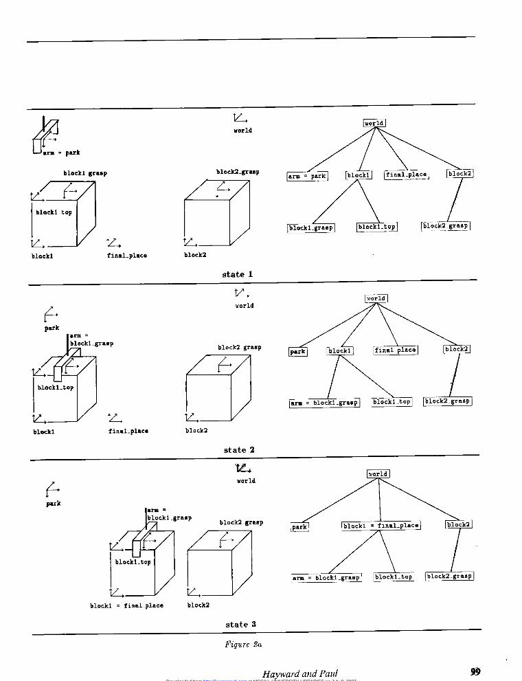
In order to illustrate our discussion, we shall borrowa simple task example from the AL system user’smanual (Mujtaba and Goldman 1981 ). The task in-volves a table top, a robot, and two blocks. The task isto grasp and move the first block, then to grasp andstack the second block on top of the first one. Figures2A and 2B show the six intermediate states necessaryto describe this task. The states are expressed in termsof frame transformations and coincidence. For the
sake of simplicity, no mention is made of trajectorygeneration and collision avoidance.
2.2.1. Description Using Af~txmentThe AL language and other languages (e.g., Latombeand Mayer 1981 ) model the geometric relationship ofthe frame with the AFFIX statement:
AFFIX f l TO f2 AT trans
where the transform trans defines the position of f 2with respect to f 1. The relationship is symmetric:whenever f 1 or f2 moves, the other frame also moves.With affixment, a situation is modeled as a tree inwhich frames correspond to nodes or leaves, andtransformations correspond to links, as in Figs. 2Aand 2B. State changes are requested through theMOVE statement:
MOVE f2 TO f3
The execution of this MOVE statement involves awalk through the a~cment tree to determine the mov-able frame arm and the trajectory that lead to the co-incidence of f2 with f3. When the motion is per-formed, the position of all the frames a~ed to themovable frame are updated.The task is described by the following sketch of
statements:
AFFIX block1_grasp TO block1 AT ...AFFIX block2_top TO block2 AT ...
AFFIX block2_grasp TO block2 AT ...MOVE arm TO block1_graspGRASP
AFFIX blockl TO arm
MOVE block1 I TO final_placeRELEASE
UNFIX blockl FROM arm
MOVE arm TO block2_graspGRASP
AFFIX block2 TO arm
MOVE block2 TO blockl_topRELEASE
UNFIX block2 FROM arm
MOVE arm TO park
© 1986 SAGE Publications. All rights reserved. Not for commercial use or unauthorized distribution. at MCGILL UNIVERSITY LIBRARIES on July 9, 2007 http://ijr.sagepub.comDownloaded from
99
© 1986 SAGE Publications. All rights reserved. Not for commercial use or unauthorized distribution. at MCGILL UNIVERSITY LIBRARIES on July 9, 2007 http://ijr.sagepub.comDownloaded from

100 © 1986 SAGE Publications. All rights reserved. Not for commercial use or unauthorized distribution.
at MCGILL UNIVERSITY LIBRARIES on July 9, 2007 http://ijr.sagepub.comDownloaded from
101
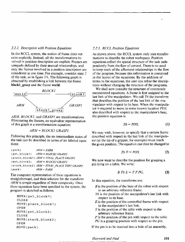
2.2.2. Description with Position EquationsIn the RCCL system, the notion of frame does notexist explicitly. Instead, all the transformations in-volved in position description are explicit. Frames areuniquely defined by their mutual relationships, andonly the frames involved in a position description areconsidered at one time. For example, consider state 2of the task, as in figure 2A. The following graph isobtained by establishing a link between the frameblockl_grasp and the frame world:
ARM, BLOCK], and GRASP] are transformations.Eliminating the frames, an equivalent representationof this graph is a transformation equation:
ARM = BLOCKI GRASPI.
Following this principle, the six intermediate states ofthe task can be described in terms of six labeled equa-tions :
(park) ARM = P,QRK
( get_block 1 ) ARM=BLOCK:I GRASP]
(place_block1 ) ARM = FINAL_PLACE GRASP]( get_block2 ) ARM=BLOCK2 GRASP2
( stack_block2 ) ARM= FINAL_PLACE TOP] GRASP2(park) ARM= PARK
The computer representation of these equations isstraightforward, and their solution for the transformARM is simple regardless of their complexity. Oncethese equations have been specified to the system, theprogram is sketched as follows:
MOVE(get_block1)CLOSE
MOVE(place_block1)OPEN
MOVE(get_block2)CLOSE
MOVE(stack_block2)OPEN
MOVE(park)
2.2.3. RCCL Position Equations
As shown above, the RCCL system only uses transfor-mations to describe the robot workspace. Positionequations reflect the spatial structure of the task inde-pendently from the flow of control. There is no needto keep track of the a~xment relationships in the flowof the program, because this information is containedin the layout of the equations. By the addition ofterms to the equations, the user can refine the descrip-tions without changing the structure of the programs.We shall now consider the structure of commonly
encountered equations. A frame is first assigned to thelast link of the manipulator. We call T6 the transformthat describes the position of the last link of the ma-nipulator with respect to its base. When the manipula-tor is required to move to some known location POS,also described with respect to the manipulator’s base,the position equation is
We may wish, however, to specify that a certain framedescribed with respect to the last link of the manipula-tor (at the tip of a gripper, for example) must reachthe given position. The equation can then be changed to
We now want to describe the position for grasping apin lying on a table. We write:
In this equation, the transforms are:
B is the position of the base of the robot with respectto an arbitrary reference frame.
T6 is the position of the manipulator’s last link withrespect to its base.
E is the position of the controlled frame with respectto the manipulator’s last link.
T is the position of the table with respect to thearbitrary reference frame.
P is the position of the pin with respect to the table.PG is a grasping position with respect to the pin.
If the pin is to be inserted into a hole of an assembly,
© 1986 SAGE Publications. All rights reserved. Not for commercial use or unauthorized distribution. at MCGILL UNIVERSITY LIBRARIES on July 9, 2007 http://ijr.sagepub.comDownloaded from

102
we define two more transforms:
AS is the position of the assembly with respect tothe table.
H is the position of the hole with respect to the as-sembly.
The corresponding equation is
A task description includes a number of these equa-tions. The system computes trajectories such thatthese equations are successively satisfied. A motionfrom one position to the next is generated by the sys-tem by implicitly inserting an additional transforma-tion in the equation. This transformation DRI VE(s)represents a rotation about an axis and a straight-linetranslation that will drive the robot from one state tothe next. The rotation and the translation are linearlydependent on a scalar variable s. The DRIVE(s) trans-formation is inserted into the position equation to theright of the controlled frame selected by the user. Theposition equations can always be rewritten as follows:
where the P;’s describe the controlled frames, the R;’sare the transform expressions to the left of the P;’s,and the EI’s are the transform expressions to the rightof the Pi’s. In order to express the motions from oneposition to the next, we write the first transform ex-pression in terms of the destination position
with
During motion, the position equation is evaluated as
with
The goal position is obtained when s = 1, such that
In RCCL, the transformations that make up the termsof the position equations actually fall into one of thefollowing categories:
Constant transformations are used to represent thegeometrical relationships of features and objectsthat remain unchanged during the execution oftrajectories. This is the basic type found in mostother robot programming systems. Constanttransformations are internally premultiplied bythe system before the actual computation of thetrajectories in order to reduce the computationalload.
Variable transformations can be read and writtenthroughout the execution of the user process. Theresulting trajectories will immediately reflect themodifications made to those transforms. The
programmer is then responsible for providingsmall smooth changes in order to obtain mean-ingful results. The changes can occur asynchron-ously, and this type of transformation is usuallyuseful for tracking applications when the sensoryinformation cannot be made available at samplerate. This is an example of communication withdata loss.
Hold transformations can be modified at arbitraryinstants by the user process. When a motion re-quest involving such a transformation is issued,the system makes a copy of it. The copy thenbecomes part of the motion request. These trans-forms find their application when positional in-formation cannot be obtained within a predictableperiod of time. They allow the user process toperform input-output operations with a transfor-mation database, for example, without having tostop the arm. This is an example of communica-tion with no loss of data.
Functionally defined transformations are attached to
© 1986 SAGE Publications. All rights reserved. Not for commercial use or unauthorized distribution. at MCGILL UNIVERSITY LIBRARIES on July 9, 2007 http://ijr.sagepub.comDownloaded from
103
a &dquo;C&dquo; function. During the computation of thecorresponding trajectory, the function is evaluatedat sample rate and is expected to compute valuesfor the transformations. If the values are func-tions of some parameter (time, for example), oneobtains parametrized trajectories. If the values arefunctions of sensor readings, one obtains synchro-nous sensory feedback for control of the arm. The
applications are limited by the execution time ofthe function, which must fit in the allocated CPUtime slot. Tracking and other active path correc-tion methods are easily implemented, however.
Position equations may include any combination oftransformation types. Section 3.4, Sensor Integration,will show examples of the use of these transformations.
2.3. TRAJECTORY GENERATION
The RCCL system handles two types of trajectories. Inboth cases, the manipulator is controlled to movetoward a target position described by a transformationequation, but the two modes differ by the way inter-mediate points are generated. In joint mode, for eachmotion request, the final manipulator position is com-puted by Eq. (7). The corresponding joint set point isthen obtained with the inverse kinematic solution ofthe arm. Intermediate set points are linearly interpo-lated in joint space. This type of motion leads to effi-cient trajectories, but the path of the controlled frameis not always easily predictable. The other type of mo-tion, or Cartesian mode, uses Eq. ( 10) to compute themanipulator position at sample rate. Joint set pointsare once again obtained by the inverse kinematics.The path of the controlled frame is then determinedby the parametric transform DRIVE(s). These pathgeneration techniques are described in more details inPaul ( 1981 ).Smooth transitions between each path segment are
provided by an interpolating, quartic polynomial.Since the position equations may contain arbitraryparametric transformations, unpredictable velocitychanges may occur at the beginning of the transition.Discontinuities of that nature also occur when thecontrol is switched from joint interpolated to Cartesianpath generation, or vice versa. These cases are handled
)
by adding a third-order polynomial to the quartictransition. The slope of the polynomial is made equalto the measured extra velocity at the beginning of thetransition. The slope is set to zero at the end of thetransition. One important feature of the trajectorygenerator is its capacity to initiate a transition at arbi-trary instants.
1
2.4. FORCE CONTROL
The RCCL system allows the user to program themanipulator so that it exerts forces and torques alongor around selected directions. The manipulator is thensaid to perform compliant motions. This capability
I raises both the problem of the motion specificationand of the control of the arm. Force controllers have
I been implemented by Raibert and Craig ( 19 $1 ) andSalisbury (1980) using feedback signals from wristforce sensors. For practical reasons, we have imple-mented a version of Paul and Shimano’s (1976) com-pliant motion scheme. Force specifications are ex-pressed in the controlled frame. Compliant motion isobtained by matching the manipulator joints witheach programmed compliant direction. For each di-rection, the joints most suitable for providing the de-sired forces or torques are selected and are force or
torque controlled, instead of being position servoed.The amount of joint force or torque to exert the de-sired forces or torque is obtained by the transposedJacobian matrix and offset by gravity compensationterms (Paul 19981):
1
where
T is the vector of forces or torques applied to the joints.S is a selection vector composed of 0’s and 1’s (the
joints corresponding to the 0 elements are positionI servoed).
RJ is the Jacobian matrix, computed in frame R.T~~,R is the function mapping forces expressed in
frame C into frame R.cf is the desired forces and torques expressed in the
controlled frame C.
© 1986 SAGE Publications. All rights reserved. Not for commercial use or unauthorized distribution. at MCGILL UNIVERSITY LIBRARIES on July 9, 2007 http://ijr.sagepub.comDownloaded from
104
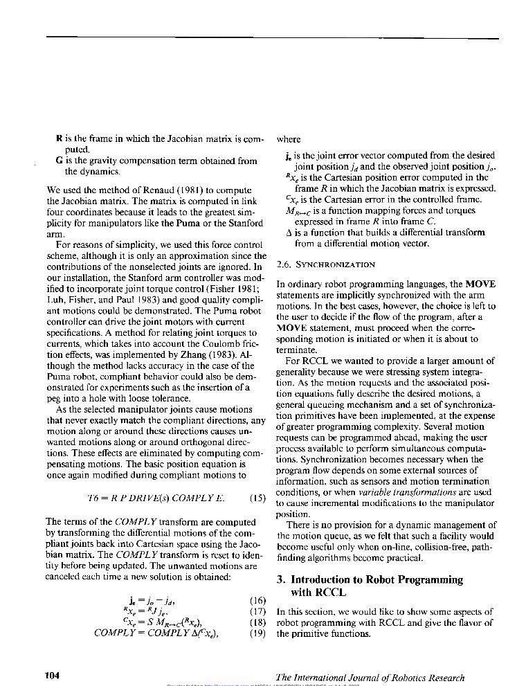
R is the frame in which the Jacobian matrix is com-puted.
,
G is the gravity compensation term obtained fromthe dynamics.
We used the method of Renaud ( 1981 ) to computethe Jacobian matrix. The matrix is computed in linkfour coordinates because it leads to the greatest sim-plicity for manipulators like the Puma or the Stanfordarm.
For reasons of simplicity, we used this force controlscheme, although it is only an approximation since thecontributions of the nonselected joints are ignored. Inour installation, the Stanford arm controller was mod-ified to incorporate joint torque control (Fisher 1981;Luh, Fisher, and Paul 1983) and good quality compli-ant motions could be demonstrated. The Puma robotcontroller can drive the joint motors with currentspecifications. A method for relating joint torques tocurrents, which takes into account the Coulomb fric-tion effects, was implemented by Zhang ( 1983). Al-though the method lacks accuracy in the case of thePuma robot, compliant behavior could also be dem-onstrated for experiments such as the insertion of apeg into a hole with loose tolerance.As the selected manipulator joints cause motions
that never exactly match the compliant directions, anymotion along or around these directions causes un-wanted motions along or around orthogonal direc-tions. These effects are eliminated by computing com-pensating motions. The basic position equation isonce again modified during compliant motions to
T6 = R P DRI VE(s) COMPL Y E. (15) }
The terms of the COMPLY transform are computedby transforming the differential motions of the com-pliant joints back into Cartesian space using the Jaco-bian matrix. The COMPLY transform is reset to iden-tity before being updated. The unwanted motions arecanceled each time a new solution is obtained:
where
je is the joint error vector computed from the desiredjoint position jd and the observed joint position jo.
Rxe is the Cartesian position error computed in theframe R in which the Jacobian matrix is expressed.
cXe is the Cartesian error in the controlled frame.M~~,~ is a function mapping forces and torques
expressed in frame R into frame C.A is a function that builds a differential transformfrom a differential motion vector.
2.6. SYNCHRONIZATION
In ordinary robot programming languages, the MOVEstatements are implicitly synchronized with the armmotions. In the best cases, however, the choice is left tothe user to decide if the flow of the program, after aMOVE statement, must proceed when the corre-sponding motion is initiated or when it is about toterminate.
For RCCL we wanted to provide a larger amount ofgenerality because we were stressing system integra-tion. As the motion requests and the associated posi-tion equations fully describe the desired motions, ageneral queueing mechanism and a set of synchroniza-tion primitives have been implemented, at the expenseof greater programming complexity. Several motionrequests can be programmed ahead, making the userprocess available to perform simultaneous computa-tions. Synchronization becomes necessary when theprogram flow depends on some external sources ofinformation, such as sensors and motion terminationconditions, or when variable transformations are usedto cause incremental modifications to the manipulatorposition.
There is no provision for a dynamic management ofthe motion queue, as we felt that such a facility wouldbecome useful only when on-line, collision-free, path-finding algorithms become practical.
3. Introduction to Robot Programmingwith RCCL
In this section, we would like to show some aspects ofrobot programming with RCCL and give the flavor ofthe primitive functions.
© 1986 SAGE Publications. All rights reserved. Not for commercial use or unauthorized distribution. at MCGILL UNIVERSITY LIBRARIES on July 9, 2007 http://ijr.sagepub.comDownloaded from
105
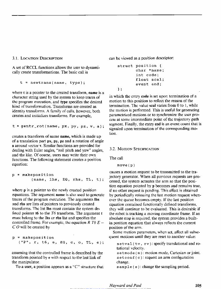
3. 1. LOCATION DESCRIPTION
A set of RCCL functions allows the user to dynami-cally create transformations. The basic call is
t = newtrans(name, type);
where t is a pointer to the created transform, name is acharacter string used by the system to keep traces ofthe program execution, and type specifies the desiredkind of transformation. Transforms are created asidentity transforms. A family of calls, however, bothcreates and initializes transforms. For example,
t = gentr-rot ( name , px, py, pz , v, a ) ;
creates a transform of name name, which is made upof a translation part px, py, pz and a rotation of anglea around vector v. Similar functions are provided fordealing with Euler angles, &dquo;roll pitch and yaw&dquo; angles,and the like. Of course, users may write their ownfunctions. The following statement creates a positionequation:
p = makeposition(name, lhs, EQ, rhs, TL, t);
where p is a pointer to the newly created positionequations. The argument name is also used to generatetraces of the program execution. The arguments Ihsand rhs are lists of pointers to previously createdtransforms. The list Ihs must contain the system de-fined pointer t6 to the T6 transform. The argument tmust belong to the Ihs or rhs list and specifies thecontrolled frame. For example, the equation R T6 E =C 0 will be created by
p = makeposition(&dquo;P&dquo;, r, t6, e, EQ, c, o, TL, e);
assuming that the controlled frame is described by thetransform pointed by e with respect to the last link ofthe manipulator.To a user, a position appears as a &dquo;C&dquo; structure that
can be viewed as a position descriptor:
struct position {char *name;int code;float scal;event end;
I ;
in which the entry code is set upon termination of amotion to this position to reflect the reason of thetermination. The value seal varies from 0 to 1, whilethe motion is performed. This is useful for generatingparametrized motions or to synchronize the user pro-cess at some intermediate point of the trajectory pathsegment. Finally, the entry end is an event count that issignaled upon termination of the corresponding mo-tion.
3.2. MOTION SPECIFICATION
The call
move(p) >
causes a motion request to be transmitted to the tra-jectory generator. When all previous requests are pro-cessed, the system actuates the arm so that the posi-tion equation pointed by p becomes and remains true,if no other request is pending. This effect is obtainedby periodically reissuing the last motion request when-ever the queue becomes empty. If the last positionequation contained functionally defined transforms,they will continue to be evaluated. This is desirable ifthe robot is tracking a moving coordinate frame. If anabsolute stop is required, the system provides a built-in position equation that always reflects the currentposition of the arm.Some motion parameters, when set, affect all subse-
quent motions until they are reset to another value:
s e t v a 1 ( t v , r v ) : specify translational and ro-tational velocity.s e t m o d e ( m ) : motion mode, Cartesian or joint.s e t c o n f ( c ) : request an arm configurationchange.s amp 1 e ( s ) : change the sampling period.
© 1986 SAGE Publications. All rights reserved. Not for commercial use or unauthorized distribution. at MCGILL UNIVERSITY LIBRARIES on July 9, 2007 http://ijr.sagepub.comDownloaded from

106
Another set of parameters affects one subsequent mo-tion :
s e t i m e ( t a , t s } : specify travel duration ts,transition time ta.e v a 1 f n ( f n ) : specify the function fn to be runin the background during the motion.distance (spec, values): specify anycombination of small translations or rotations,expressed in the controlled frame, as modifiers forthe goal position. -
1 i m i t ( s p e c , v a 1 u e s ) : specify forces andtorques limit values along or around selecteddirections. The same function serves to specifymaximum differential motions.c omp 1 y ( d i r s , va 1 u e s ) : causes the arm toenter active comply mode when the next motionbegins and to exert forces or torques until reset inposition servo mode.1 o c k ( d i r s } : reset the arm in position servomode along or around the selected directions.u p d a t e ( t r a n s , e q u a ) : calculates the valueof the transform trans in the equation when themotion ends.
This set of functions serves to build a motion requestpacket that contains all the information necessary togenerate a motion. The functions listed above only fillentries in a &dquo;C&dquo; structure. The choice of these func-tions is somewhat arbitrary, and any program able tosupply such a motion request packet could control thearm equally well.
3.3. SYNCHRONIZATION ,
Synchronization is achieved through two basic mecha-nisms : (1) user process suspension and (2) motioninterruption. Two primitives can be used to synchro-nize the program flow:
waitfor(event)waitas(predicate) >
The macro waitfor suspends the program executionuntil the specified event occurs. Event counts are sig-naled by the trajectory generator or by the backgroundfunctions set up by the user. They are waited for bythe user’s foreground process. The macro waitas re-peatedly evaluates its argument until it yields a non-zero value, and then allows the program execution toproceed.The use of the seal and end fields in a position de-
scriptor leads to various coding combinations. Forexample, let pO, pl, p2, and p3 describe the fourcorners of a square. Let the manipulator move aroundthe square, causing synchronous processing to begineach time the manipulator moves through pO:
for ( i - 0; i < 4; ++i ) {move(p~);move(p1);move(p2);move(p3);
}waitfor(p0->end);printf(&dquo;starting first squareBn&dquo;);waitfor{p0->end)printf(&dquo;starting second squareBn&dquo;);etc...,
Consider the implementation of a grasping sequencein three steps. First, the tool is moved to an approachposition defined by translating the final position alongthe negative z-axis of the tool frame. Then, the tool ismoved to the final position. In the last step, the arm iscommanded to stop at the final position for 400 milli-seconds and the gripper to close at the middle of thisperiod of time.
p->end - 0; /* reset count ~*/
dfstance(&dquo;dz&dquo;, , -10.);l~ backup 10 mm */
move(p); /* move approach */
move(p); /* move final */
setime(0, 400); /* during 400 ms */
move(p); /* stay there */
© 1986 SAGE Publications. All rights reserved. Not for commercial use or unauthorized distribution. at MCGILL UNIVERSITY LIBRARIES on July 9, 2007 http://ijr.sagepub.comDownloaded from

107
waitfor(p->end) /* wait for motion*/
waitfor(p->end) /* completion */
waitas(p->scal > .5) /* wait half time */
CLOSE /* close hand */
The following example takes advantage of the pro-gram asynchrony with respect to the motions in orderto obtain locations stored in a database. The accesstime is not predictable. The function gettr obtainsvalues until NO is returned. Although the responsetime of gettr is random, there is no need to stop the arm:
e = gentr...ref = gentr...loc = newtrans(&dquo;LOC&dquo;, , hold);
p = makeposition(&dquo;P&dquo;, , t6, e, EQ, ref, loc, TL, e);
while(gettr(loc) != NO) {move(p);
}
The robot will wait for new data if it can execute themotions faster than gettr can provide values. If this isnot the case, the overflow of the motion queue needsto be prevented. The program is slightly modified tomake use of the global variable nbrequest maintainedby the system to reflect the number of nonserved re-quests.
while (gettr(loc) != NO) {waitas(nbrequest < MAX)move(p);
}
Next, we would like to illustrate how motions canbe interrupted on external events. The following pro-gram causes the arm to move to some location and tostop at the position it occupies when the user hits <re-
turn> at the terminal. Within the same position equa-tion, the update primitive records the location at thetime the motion is interrupted. We shall introducetwo more system variables: nextmove and completed.
The variable nextmove interrupts a motion whenever itis set to a nonzero value, and its value is stored in thecode field of the corresponding position descriptor.The variable completed is an event signaled wheneverthe motion queue becomes empty.
update(loc, p);move(p);printf(&dquo;hit <return> to stop the armBn&dquo;);getchar();nextmove = YES;waitfor(completed)if (p->code != YES)
printf(&dquo;The ar.m was in P’
when <return> was hitBn&dquo;);
3.4. SENSOR INTEGRATION
Sensors are used to modify the behavior of a robot atrun time and allow it to deal with uncertainties intime and space. There is a wide variety of sensors andinformation likely to be collected. The RCCL primi-tives are neither concerned with particular sensors, norwith the nature of the acquired information, nor bythe way it is processed. The primitives provide themeans for an efficient utilization of sensory informa-tion by the robot.
3.4.1. Active Path Correction
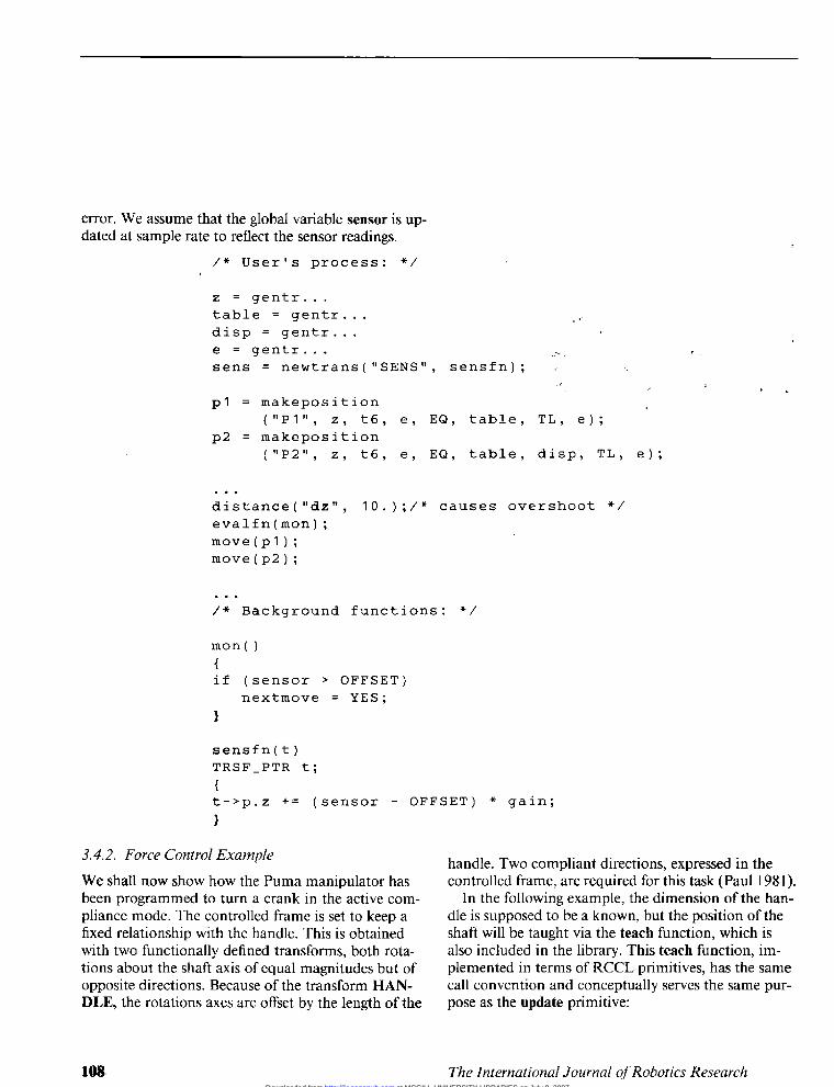
Active path correction is obtained by synchronouslyupdating functionally defined transformations fromsensor readings. The next example demonstrates thistechnique with a proximity sensor. The sensor, fixedwith respect to the manipulator’s last link, measuresthe distance along the z-axis of the controlled frame.The corrections are made along the same direction.The manipulator is programmed to move close to asurface. This type of motion is conceptually similar toa compliant motion, because the motion along z isdetermined by the geometry of the surface. A func-tional transform is used to cause the arm velocityalong the z-axis to be proportional to the position
© 1986 SAGE Publications. All rights reserved. Not for commercial use or unauthorized distribution. at MCGILL UNIVERSITY LIBRARIES on July 9, 2007 http://ijr.sagepub.comDownloaded from
108
error. We assume that the global variable sensor is up-dated at sample rate to reflect the sensor readings.
/* User’s process: */ ..
z = gentr...table - gentr... ,..
disp = gentr... ,
e = gentr.... ’-sens = newtrans(&dquo;SENS&dquo;, sensfn); ...
p1 = makeposition
’
,’(&dquo;P1&dquo;, z, t6, e, EQ, table, TL, e);
p2 = makeposition(&dquo;P2&dquo;, z, t6, e, EQ, table, disp, TL, e):
distance(&dquo;dz&dquo;, 10.);/* causes overshoot */
evalfn(mon);move(p1);move(p2);
i..
/* Background functions: */
mon(){if (sensor > OFFSET)
nextmove = YES;
}
sensfn(t)TRSF_PTR t;{t->p.z += (sensor - OFFSET) * gain;
}
3.4.2. Force Control ExampleWe shall now show how the Puma manipulator hasbeen programmed to turn a crank in the active com-pliance mode. The controlled frame is set to keep afixed relationship with the handle. This is obtainedwith two functionally defined transforms, both rota-tions about the shaft axis of equal magnitudes but ofopposite directions. Because of the transform HAN-DLE, the rotations axes are offset by the length of the
handle. Two compliant directions, expressed in thecontrolled frame, are required for this task (Paul 1981 ).
In the following example, the dimension of the han-dle is supposed to be a known, but the position of theshaft will be taught via the teach function, which is
,
also included in the library. This teach function, im-plemented in terms of RCCL primitives, has the samecall convention and conceptually serves the same pur-pose as the update primitive:
© 1986 SAGE Publications. All rights reserved. Not for commercial use or unauthorized distribution. at MCGILL UNIVERSITY LIBRARIES on July 9, 2007 http://ijr.sagepub.comDownloaded from

109
/* User’s process: */ ’
rotpx = newtrans(&dquo;ROTPX&dquo;, pxfn);rotnx = newtrans(&dquo;ROTNX&dquo;, nxfn); i
handle = gentr_trsl(&dquo;HANDLE&dquo;, ... >
.
e = gentr...z = gentr...
get = makeposition(&dquo;GET&dquo;, ~
z, t6, e, EQ, shaft, handle, TL, e); .
turn = makeposition(&dquo;TURN&dquo;,z, t6, e, EQ, shaft, rotpx, ~
handle, rotnx, TL, e); I ’
_
-
: -
move(get);teach(shaft, get);CLOSE
comply(&dquo;fx fz&dquo;, 0., 0.);update(handle, get);turns = 4; /* 4 turns */
setime(200, 4000 * turns); /* 4 sec per turn */
move(turn);waitfor(turn->end);OPEN
’
lock(&dquo;fx fz&dquo;);distance(&dquo;dx&dquo;, -50.);move(get); /* depart */
/* Background function attached to the functional transforms: */
pxfn(t) ’
TRSF_PTR t;{rot(t, xunit, turn->scal*360*turns);
}
nxffn(t)TRSF_PTR t;f I
rot(t, yunit, - turn->scal*360*turns);1
4. Conclusion
The integration of robot manipulator control withinthe &dquo;C&dquo; programming language has been performed as
Ia library of functions, in the same manner as is input-output. Manipulator task description has been sepa-rated into two parts: a world model and motion sched-
uling. Positions descriptions are implemented in terms1
1
© 1986 SAGE Publications. All rights reserved. Not for commercial use or unauthorized distribution. at MCGILL UNIVERSITY LIBRARIES on July 9, 2007 http://ijr.sagepub.comDownloaded from

110
of graphs representing closed kinematic chains. Theelements of these chains are homogeneous transforma-tions that may be parameterized in terms of time, andsensor readings. Motion requests allow the user tospecify a desired position together with force and dis-tance modifiers. The position information gained asmotions are made may be reintegrated in the worldmodel by means of an update primitive.RCCL is a powerful programming system and may
be extended as desired, since programming is in the&dquo;C&dquo; under the Unix system. For example, one versionof the system generates off-line trajectory files suitablefor graphics display, instead of running the manipulator.We are considering using interpreted languages,
such as Lisp, as a base to develop robot programs inan interactive fashion and using RCCL as the underly-ing, real-time control system. Furthermore, if special-ized languages are needed, the software packages LEXand YACC (Johnson 1980), available under Unix,provide a suitable environment for rapidly creatingthese languages.The programming of robot manipulators requires a
level of language suitable to express motion algo-rithms. We believe that languages such as Pascal and&dquo;C&dquo; are of the appropriate level. The fact that robotmotion algorithms expressed in these languages are notsimple reflects the complexity of the algorithms ratherthan the complexity of the language. Simple applica-tion robot packages could, of course, be written inRCCL and would have all the attributes of user friend-liness as well as the limitations. Finally, we have foundthe system useful as a research tool, since new algo-rithms can be tested at any level of the control hierar-
chy. The system is currently being transferred to anumber of small machines and currently supports anumber of research projects.
5. Acknowledgments ’
We wish to thank the following persons who contrib-uted to this project: Bill Fisher, Hong Zhang, JuanJuan, and George Goble. We also wish to thank JohnLloyd, who helped us with the section on the arminterface, and the reviewers, who commented on anearlier draft of this paper.
Appendix
The material in this section is based on Lloyd (1985).The VAX/Unix architecture required some modifica-tions to be made to the standard software. These are:
- The VAX is a virtual memory machine. Seg-ments of the program can be present either in fastmemory or paged out on secondary storage. Sincethe control-level software is executed in kernelmode at elevated priority, all the codes and datathat it references must be resident in fast memory.A special locking mechanism and a linking proce-dure have been developed for this purpose.
-The address translation is temporarily altered atinterrupt time to allow the control process andthe planning process to access a shared area ofmemory.
-A particular problem associated with runningfunctions in kernel mode on VAX systems is thatrun-time, hardware-detected errors will result in asystem crash. Because it is assumed that the oper-ating system is largely bug free, any errors that dooccur should result in system crash. A modifica-tion was made so that while the user functions are
executing, a flag is raised indicating their presenceto the kernel. Hardware errors occuring at thistime are hence recognized as belonging to thecontrol program, and instead of causing a crash,they result in a Unix error signal being sent to thecontrol program.
REFERENCES
Fisher, D. W. 1981. The modification of a robotic manipu-lator and digital controller to incorporate both force andposition control. Master’s thesis, Purdue University, De-partment of Electrical Engineering.
Hayward, V. 1983a. Robot real time user’s manual. TR-EE83-42. West Lafayette, Ind.: Purdue University, Depart-ment of Electrical Engineering.
Hayward, V. 1983b. RCCL Version 1.0 User’s Manual.TR-EE 83-46. West Lafayette, Ind.: Purdue University,Department of Electrical Engineering.
Johnson, C. S. 1980 (Aug.). Language development toolswith the Unix operating system. Computer, pp. 16-21.
Kernighan, B. W., and Ritchie, D. M., "The C ProgrammingLanguage," Prentice-Hall, 1980.
© 1986 SAGE Publications. All rights reserved. Not for commercial use or unauthorized distribution. at MCGILL UNIVERSITY LIBRARIES on July 9, 2007 http://ijr.sagepub.comDownloaded from

111
Kosman, D. 1986. Adapting a high-level robot control envi-ronment for an industrial robot. M.Eng. thesis, McGillUniversity, Department of Electrical Engineering.
Latombe, J. C., and Mayer, E. 1981 (Tokyo). LM: A high-level language for controlling assembly robots. Proc 11thInt. Symp. Indust. Robots.
Lloyd, J. 1985. Implementation of a robot control develop-ment environment. M.Eng. thesis, McGill University,Department of Electrical Engineering.
Lozano-Perez, T. 1983. Robot programming. Proc. IEEE71(7), pp. 821-841.
Luh, J. Y. S., Fisher, W. D., and Paul, R. P. 1983. Jointtorque control by direct feedback for industrial robots.IEEE Trans. Autom. Contr. AC-28 (2).
Mujtaba, S., and Goldman, R. 1981. AL user’s manual.AIM-344, Stanford, Calif.: Stanford University ArtificialIntelligence Laboratory.
Nitzan, D., and Rosen, C. A. 1976. Programmable industrialautomation. IEEE Trans. Comp. C-25 (12) pp. 1259-70.
Paul, R. P. 1977 (Mar.). WAVE: A model based languagefor manipulator control. Indust. Robot 4(1):10-17.
Paul, R. P. 1979. Manipulator path control. IEEE Trans.Sys., Man, Cyber. SMC-9 (11):702-711.
Paul, R. P., and Shimano, B. 1976 (San Francisco). Compli-ance and control. Proc. Joint Conf. Autom. Contr., pp.679-699.
Paul, R. Robot Manipulators: Mathematics, Programming,and Control. MIT Press, 1981.
Raibert, M. H., and Craig, J. J. 1981. Hybrid position/forcecontrol of manipulators. Trans. ASME J. Dyn. Sys.,Meas., Contr. 103:126-133.
Renaud, M. 1981 (Oct., Tokyo). Geometric and kinematicmodels of a robot manipulator: calculation of the Jacobianmatrix and its inverse. Proc. 11th Int. Symp. Indust.Robots, pp. 757-763.
Salisbury, J. K. 1980 (Albuquerque, N. Mex.). Active stiff-ness control of a manipulator in Cartesian coordinates.Proc. 19th Conf. Decision and Contr. 1:95 -100.
Schwan K., et al. 1985 (St. Louis, Mo.). GEM: operatingsystem primitives for robots and real-time control systems.IEEE Int. Conf Robotics and Automation, pp. 807-813.
Shimano, B. E., Geshke, C. C., and Spalding, C. H. 1983.VAL-II: a robot programming language and control sys-tem. 1983 ISRR, Bretton Woods, N.H.
Takase, K., Paul, R. P., and Berg, E. J. 1979 (Chicago). Astructured approach to robot programming and teaching.IEEE COMPSAC. pp. 273-278.
Taylor, R. H. 1983. An integrated robot system architecture.Report RC-9824. Yorktown Heights, N.Y.: IBM ResearchCenter. pp. 57-63.
Taylor, R. H., Summers, P., and Meyers, J. 1982. AML: amanufacturing language. Int. J. Robotics Res. 1(3).
Zhang, H. 1983. Determination of the simplified dynamics of the Puma manipulator. Tech. Rep. West Lafayette,Ind.: Purdue University, Department of Electrical Engi-neering.
© 1986 SAGE Publications. All rights reserved. Not for commercial use or unauthorized distribution. at MCGILL UNIVERSITY LIBRARIES on July 9, 2007 http://ijr.sagepub.comDownloaded from