vi pec manual
TRANSCRIPT

VX Wiring and Installation Manual
V44 & V88
Copyright 2010 Vi-PEC

VX Wiring and Installation Manual2
© 2010 Vi-PEC
Table of Contents 0
Part I Introduction 4
................................................................................................................................... 41 Support Options
Part II Choosing a Configuration 5
................................................................................................................................... 51 Injector Outputs
................................................................................................................................... 62 Ignition Outputs
................................................................................................................................... 63 AuxiliaryOutputs
................................................................................................................................... 74 Analog/Temperature Inputs
................................................................................................................................... 75 Digital Inputs
................................................................................................................................... 86 Trigger Inputs
................................................................................................................................... 87 Summary
................................................................................................................................... 108 Installer IO Table
Part III Component Installation Locations 12
................................................................................................................................... 121 ECU Location
................................................................................................................................... 122 Ignition Component Placement
................................................................................................................................... 133 MAP Sensor Location
Part IV V44 Header Pinout 13
Part V V88 Header Pinout 14
Part VI Power and Ground Wiring 15
................................................................................................................................... 151 Power Supplies
................................................................................................................................... 162 +14V In
................................................................................................................................... 163 +14V Aux9/10
................................................................................................................................... 174 Power Ground
................................................................................................................................... 175 Sensor Ground
................................................................................................................................... 176 +5V Out
................................................................................................................................... 177 +8V Out
................................................................................................................................... 188 ECU Hold Power Wiring
Part VII Input Signal Wiring 19
................................................................................................................................... 191 Trigger Inputs
.......................................................................................................................................................... 20Reluctor/Magnetic Sensors
.......................................................................................................................................................... 21Hall/Optical/Proximity Sensors
................................................................................................................................... 222 MAP Sensor
................................................................................................................................... 243 TPS Wiring
................................................................................................................................... 254 Engine Coolant Temperature Sensor
................................................................................................................................... 255 Intake Air Temperature Sensor
................................................................................................................................... 266 Narrow Band Oxygen Sensor
................................................................................................................................... 277 Wide Band Oxygen Sensor
3Contents
3© 2010 Vi-PEC
................................................................................................................................... 288 GP Pressure & Temperature Sensing
................................................................................................................................... 289 Digital Input Wiring
Part VIII Output Wiring 30
................................................................................................................................... 301 Fuel Injector Drives
.......................................................................................................................................................... 30High Impedance Injectors
.......................................................................................................................................................... 31Low Impedance Injectors
.......................................................................................................................................................... 32Injection Mode
................................................................................................................................... 342 Ignition Drives
.......................................................................................................................................................... 34Igniter Requirements
.......................................................................................................................................................... 35Coil Requirements
.......................................................................................................................................................... 35Ignition System Wiring
.......................................................................................................................................................... 36Distributor Ignition
.......................................................................................................................................................... 37Multi-Coil Wasted Spark Ignition
.......................................................................................................................................................... 39Multi-Coil Direct Spark Ignition
................................................................................................................................... 393 Auxiliary Output Wiring
.......................................................................................................................................................... 40Low Side Driving (Switching To Ground)
.......................................................................................................................................................... 40High Side Driving (Switching Power Supply)
.......................................................................................................................................................... 41Switching Through a Relay
.......................................................................................................................................................... 41Switching an LED
................................................................................................................................... 424 Idle Speed Control
.......................................................................................................................................................... 42Two Terminal ISC Solenoid
.......................................................................................................................................................... 43Three Terminal ISC Solenoid
.......................................................................................................................................................... 44Four Terminal ISC Stepper Motor
.......................................................................................................................................................... 45Six Terminal ISC Stepper Motor
................................................................................................................................... 455 Tachometer
................................................................................................................................... 456 Variable Valve Timing (VVT) Solenoids
................................................................................................................................... 477 Electronic Throttle Control
Part IX Rotary Engine Wiring 47
................................................................................................................................... 471 Rotary Injection Wiring
................................................................................................................................... 482 Rotary Ignition Wiring
................................................................................................................................... 483 Metering Oil Pump Wiring
Part X PC Tuning 50
................................................................................................................................... 501 Installing USB Drivers
................................................................................................................................... 502 Installing Vi-PEC Tuning Software Tuning Software
................................................................................................................................... 513 Communicating With Your ECU
Part XI First Time Setup 52
................................................................................................................................... 521 Pre-start Checks
................................................................................................................................... 522 Initial Setup
................................................................................................................................... 573 Trigger Calibration
................................................................................................................................... 584 First Time Startup
................................................................................................................................... 595 Essential Tuning Adjustments
Index 61

VX Wiring and Installation Manual4
© 2010 Vi-PEC
1 Introduction
Thank you for purchasing your Vi-PEC Wire-In Engine Control Unit (ECU). Vi-PEC VX ECU'sare an advanced, fully programmable microprocessor controlled Engine ManagementSystem.
The VX software platform boasts an impressive list of features giving a new level of useradjustment. This flexibility allows the tuner to have complete control over the enginemanagement system. VX software employs high resolution fuel and ignition tables withconfigurable load and RPM centres. Coupled with up five dimensional fuel and ignitionmapping, barometric pressure compensation and intake air temperature correction this givesan unprecedented level of tuning accuracy. VX ECU's are in field upgradeable, no need toreturn the ECU for software updates.
All Vi-PEC VX Wire-In Engine Management Systems are designed with flexibility and ease ofinstallation in mind. Vi-PECWire-In systems are deigned to be wired to either existing wiringor preferably as a complete re-wire. In some cases adapter looms or header boards can bepurchased to allow wiring of the VX ECU to factory ECU headers. Contact your nearest Vi-PEC dealer for more information on these.
Vi-PEC Engine Management Systems are designed with the final result in mind. Not only dothey boast an impressive range of performance features, but are designed with a focus onsafety, reliability and drive-ability. However, the ultimate success of your engine managementupgrade is determined by how well the system is installed and tuned.
Installing and tuning any after-market engine management system is not to be taken lightly. VX ECU's give the tuner the control & flexibility that only top after-market engine managementsystems in the world can provide. While every effort has been made to keep VX ECU's asuser friendly as possible, it should be recognised that added features bring added complexity.
The complete set-up of your ECU can be divided into two equally important tasks.
1. This manual covers the wiring and installation of your VX ECU. While it is not strictlyessential that this work is performed by an automotive electrician, the knowledge and toolsavailable to these professionals makes it highly recommended. Regardless of who does the installation, it is of utmost importance that clean and robust connections are madethroughout the installation. A significant majority of after market engine managementfailures are due to poor wiring practices. Note that use of complex features such asVariable Valve Timing, Electronic Throttle Control and ECU Hold Power require advancedwiring practice.
2. Once the VX ECU has been installed it will need to be tuned using a laptop computer withVi-PEC Tuning Software Tuning Software software. Information on the configuration andtuning of the VX ECU is detailed in the online help section of Vi-PEC Tuning SoftwareTuning Software. VX ECU's are shipped pre-loaded with a base configuration that shouldbe close enough to get most engines running after a few application specific adjustmentshave been made. While hearing the engine running on the new ECU for the first time isalways a satisfying feeling, it is important to realise that the job is not complete. Theamount of tuning performed and the experience of the tuner are the two most importantfactors in determining how happy you will be with your engine management system.
1.1 Support Options
Should any issues arise during installation, the following options exist for technical support:
1. Contact your nearest Vi-PEC dealer. A Vi-PEC dealer list is available on our website:

Introduction 5
© 2010 Vi-PEC
www.Vi-PEC.com
2. Technical Support Email: [email protected]
3. Online Discussion Board: Available from the Vi-PEC website.
The majority of questions received by the technical support team are clearly answered in themanuals. To speed up your technical inquiry please consult the manuals to make sure thatyour question has not already been answered.
2 Choosing a Configuration
As all VX inputs/outputs are configurable, the required connections will be highly dependenton the application. Read this section carefully to ensure the correct functions are chosen.
The first step in installing a VX ECU is to decide what function each of the configurable inputsand outputs will provide.
The VX ECU's have the following input / output pins:
IO V44 V88
Injection Drives 4 x Saturated 8 x Peak & Hold
Ignition Drives 4 8
Auxiliary Outputs 8 10
Digital Inputs 3 or 4* 10
Analogue Voltage Inputs 3/4* + Internal MAP 11
Temperature Inputs 2 4
Knock Sensor Inputs 0 2
Regulated Outputs +8V & +5V +8V & +5V
Trigger Inputs 2 2
* V44 shares one header pin for DI4 and An Volt 2
2.1 Injector Outputs
The V88 has eight independent current controlled (Peak and Hold) injector drives allowingsequential, sequential staged, group and group staged fuel injection. These injection drivesare designed to be used with low or high impedance injectors without the use of ballastresisters. Unused Injection channels can be used for additional auxiliary outputs.
The V44 has four independent saturated injector drives allowing sequential, group and groupstaged fuel injection. These injection drives are designed to be used with high impedanceinjectors. Injector ballast resistors must be wired if low impedance injectors are to be used. Unused Injection channels can be used for additional auxiliary outputs.
VX Injection Specifications:

VX Wiring and Installation Manual6
© 2010 Vi-PEC
Max Peak Current = 10 A
Max Hold Current = 3 A
Max Saturated Injection or Auxiliary Output Current = 5 A
Open Collector (not fly-wheeled) in auxiliary output mode.
2.2 Ignition Outputs
The V88 offers eight independent ignition drives which can be used in a wide range ofconfigurations from a basic distributor set-up through to more complex multi-coilarrangements. Unused ignition channels can be used for additional auxiliary outputs (simpleswitching functions only). All direct spark, wasted spark and distributed ignitionconfigurations requiring up to eight channels are supported by the V88
The same as above applies for the V44 however the V44 has four ignition outputs.
VX Ignition Specifications:
Ignition Drive High 20mA @ 5V
Ignition Drive Low 2A over current protected
Open Collector (not fly-wheeled) in auxiliary output mode.
2.3 AuxiliaryOutputs
VX Wire in ECU's have eight general purpose auxiliary outputs. Unused ignition and injectionchannels can also be used as auxiliary outputs. Auxiliary outputs are general-purposeoutputs that may be used to perform a wide range of functions. However, the followinglimitations apply:
A Three Terminal ISC Solenoid must be wired to Aux 1 and Aux 2.
An ISC Stepper Motor must be wired to Aux 5, Aux 6, Aux 7 and Aux 8.
Variable Valve Timing (VVT) solenoids must be wired to Aux 1 to 4.
Aux 5 to 8 can not be Pulse Width Modulated (PWM) above 300Hz. Note that PWMfrequencies above 300 Hz may be required to drive a tachometer for a V8 above 4500RPM.An electronic throttle motor must only be wired to Aux 9 (+) and Aux 10 (-).
Spare Injection and Ignition channels when used as auxiliary outputs can only be usedas Auxiliary Outputs.
Auxiliary outputs supply an earth to switch loads such as a solenoid, relay, bulb or LED. Allauxiliary outputs may be used as a conditional switch that becomes activated at a certainvalue (e.g. Honda VTEC), or for more complex control operations such as as idle speedcontrol and electronic boost control.
Loads may be connected directly to the auxiliary output without using a relay provided they donot draw more than 2A of current. Essentially this means that a directly connected loadshould have a resistance exceeding 7Ω. Refer to the section on wiring auxiliary outputs.
Some of the functions that may be performed by auxiliary outputs include:
Fuel Pump Relay Switching (highly recommended for safety reasons)
Engine Coolant Fan Relay Switching
Electronic boost control using a boost control solenoid (uses PWM)
Variable valve timing solenoid (e.g. VTEC)
Warning / Check Engine Light
Purge Control
EGR Control

Choosing a Configuration 7
© 2010 Vi-PEC
Any function requiring an output activated by temperature, manifold pressure (MAP),RPM, gear position, digital input state etc.Water Injection / nitrous oxide control (uses PWM)
Inter-cooler Water Spray
Air Conditioning Clutch / Fan
General Purpose PWM
Idle Speed Control solenoids or stepper motors
Electronic Throttle Control
VX Auxiliary Output Specifications:
1.5k Ohm Internal Pull-up Resister
Auxiliary Drive Low 2A over-current protected
Open Collector (fly-wheeled) in auxiliary output mode.
Aux 5 to 8 High Side Drive (ISC Stepper Mode) 0.5 A.
Aux 9 and 10 (V88 only) Push-Pull drive 4/4 A.
2.4 Analog/Temperature Inputs
VX ECU's have plentiful analogue voltage and analogue temperature channels. Thedifference between volt and temperature channels is temperature channels have an internalpull-up resister.
All analogue volt channels are created equal and can be wired to any type of analogue input(there is no restrictions as to what must be wired to each channel).
Analogue Volt Inputs may be configured to accept an analogue signal between 0-5V. Applications include:
Narrow-band O2 (0-1V output)
Wide-band O2 (via external wide-band controller)
0-5V Voltage (e.g. Boost Adjust)
Pressure (from 0-5V transducer)
Temperature channels are designed to be used only with PTC or NTC thermistor sensors. Almost all factory temperature sensors fit this category. Do not wire the output of a 0-5Vtemperature sensor (e.g. a pyro. module) to these channels, instead use an AnalogueVoltage Input.
Analogue Channel Specifications:
Measurable Input Range 0-5V DC
Input impedance 2.2M Ohm DC (4.7k Ohm AC).
Maximum Input Voltage +/- 50 V
Temperature Channel Pull-up Resister 1k Ohm to 5V
2.5 Digital Inputs
Digital Inputs are inputs that recognise either a high (+V) or low (GND) signal. Digital inputsare typically set-up to monitor the position of manual switches or connected to sensors thatoutput a signal of variable frequency.
The following Digital Input Limitations Apply:
Only Digital Inputs 1 to 6 can be used for frequency input (e.g. speed).
Only Digital Inputs 1 to 4 can be used for Variable Valve Timing (VVT) cam positioninput.

VX Wiring and Installation Manual8
© 2010 Vi-PEC
VX ECU's have up to 10 Digital Inputs that can be configured for sensors/ switches such as:
Vehicle Speed Sensor
Antilag Switch
Clutch Switch (for launch control and flat shifting)
High / Low Boost Switch
Water Spray Switch
Dual Fuel / Ignition Map Switch
Nitrous Oxide Switch
Anti-theft Switch
AC Request Switch
Digital Inputs have a software selectable pull-up resister that can be enabled when measuringfrom ground switching devices (such as hall effect sensors).
Digital Input Specifications:
Low Level Input < 1V
High Level Input > 2 V
Digital Input Pull-up Resister (if enabled) 4k7 Ohm to 12V
Maximum input voltage +/- 50 V
2.6 Trigger Inputs
Trigger inputs are required from crank/cam angle sensor(s) (CAS) for the VX ECU tocalculate the current engine speed and position.
VX ECU's use on board digital trigger decoding to to determine engine position from the givensignals. Set-up of the trigger inputs is performed using Vi-PEC Tuning Software TuningSoftware. Contact your nearest Vi-PEC dealer for advice on wiring and set-up of triggerinputs if unsure.
Trigger 1 is used to determine crankshaft position. Trigger 2 is used to determine theengines position in the firing order. In all cases Trigger 1 will need to be used. In many casesTrigger 2 must also be used.
Engines with Variable Valve Timing may also require Digital Inputs be wired to cam shaftposition sensors.
Refer to the Trigger Wiring section for more information about trigger requirements fordifferent ignition/injection set-ups.
2.7 Summary
After reading this chapter you should be able to complete a list outlining the basicconfiguration that will be used. It is important to write such a list as you will need to set upeach output in Vi-PEC Tuning Software Tuning Software later on. An example of such a listis shown below. A blank table to be filled out by the installer is given in the following chapter.
Configuration: 6 Cylinder, direct spark, sequential injection, turbocharged,variable valve timing
Trigger 1 Crank Angle Sensor
Trigger 2 Cam Angle Sensor
Analogue Volt 1 MAP Sensor (Vi-PEC 2.5 Bar)

Choosing a Configuration 9
© 2010 Vi-PEC
Configuration: 6 Cylinder, direct spark, sequential injection, turbocharged,variable valve timing
Analogue Volt 2 Throttle Position (TPS)
Analogue Volt 3 After market Wide-band O2 Controller
Analogue Volt 4 Factory Narrow Band O2 (0-1V)
Analogue Volt 5 to 8 N/C
Analogue Temp Input 1 Engine Coolant Temperature
Analogue Temp Input 2 Inlet Air Temperature
Analogue Temp Input 3 Fuel Temperature
Analogue Temp Input 4 N/C
+5V Out TPS and MAP sensor power
+8V Out Cam/Crank angle sensor power supply
Ignition 1 Igniter Channel 1 (Cylinder 1)
Ignition 2 Igniter Channel 2 (Cylinder 2)
Ignition 3 Igniter Channel 3 (Cylinder 3)
Ignition 4 Igniter Channel 4 (Cylinder 4)
Ignition 5 Igniter Channel 5 (Cylinder 5)
Ignition 6 Igniter Channel 6 (Cylinder 6)
Ignition 7 Fuel Pump Relay
Ignition 8 A/C Clutch Relay
Injection 1 Injector 1 (Cylinder 1)
Injection 2 Injector 2 (Cylinder 2)
Injection 3 Injector 3 (Cylinder 3)
Injection 4 Injector 4 (Cylinder 4)
Injection 5 Injector 5 (Cylinder 5)
Injection 6 Injector 6 (Cylinder 6)
Injection 7 Fuel Pump Speed Control 1
Injection 8 Fuel Pump Speed Control 2
Auxiliary Output 1 Idle Speed Control Solenoid (Close)
Auxiliary Output 2 Idle Speed Control Solenoid (Open)
Auxiliary Output 3 Tachometer
Auxiliary Output 4 Variable Valve Timing Solenoid
Auxiliary Output 5 Inter-cooler Water Spray
Auxiliary Output 6 Shift Light
Auxiliary Output 7 A/C Fan Relay
Auxiliary Output 8 Boost Control Solenoid
Digital Input 1 Vehicle Speed
Digital Input 2 Variable Valve Timing Cam Position Sensor

VX Wiring and Installation Manual10
© 2010 Vi-PEC
Configuration: 6 Cylinder, direct spark, sequential injection, turbocharged,variable valve timing
Digital Input 3 A/C Request Switch
Digital Input 4 I/C Spray Switch
Digital Input 5 Start Position Switch
Digital Input 6 Power Steer Switch
Digital Inputs 7 to 10 N/C
Example of usage of inputs and outputs
2.8 Installer IO Table
Fill out the following table to assist in installation. It will come in useful when configuringinputs and outputs in Vi-PEC Tuning Software Tuning Software. It is important to note that notall ECU types have all of these inputs/outputs available.
Installer I/O Table
Function Connection Example
Trigger 1 Crank Angle Sensor Reluctor,Proximity, Opticalor Hall
Trigger 2
Analog Temp Input 1 NTC Thermistorsensors Only
Analog Temp Input 2
Analog Temp Input 3
Analog Temp Input 4
Analog Volt 1 0-5V Input fromsensor or externalcontroller
Analog Volt 2 (Shared with DI4 on V44)
Analog Volt 3
Analog Volt 4
Analog Volt 5 (Internal MAP on V44)
Analog Volt 6
Analog Volt 7
Analog Volt 8
Analog Volt 9
Analog Volt 10
Analog Volt 11
+5V Out TPS and MAP sensor power +5V Power OUT
+8V Out
Ignition 1 Use spare Ignitionchannels forswitching typeAuxiliary Outputs
Ignition 2
Ignition 3

Choosing a Configuration 11
© 2010 Vi-PEC
Installer I/O Table
Ignition 4
Ignition 5
Ignition 6
Ignition 7
Ignition 8
Injection 1 Wire Inj 1 to cyl 1, 2 to 2, 3to 3etc...
Use spareInjection channelsfor switching typeAuxiliary Outputs
Injection 2
Injection 3
Injection 4
Injection 5
Injection 6
Injection 7
Injection 8
Auxiliary Output 1 High FrequencyPWM or VVTControl. 3W-ISC Solenoidmust be wired toAux1 & Aux2.
Auxiliary Output 2
Auxiliary Output 3
Auxiliary Output 4
Auxiliary Output 5 PWM less than300 Hz or GPswitching.ISC Stepper
Auxiliary Output 6
Auxiliary Output 7
Auxiliary Output 8
Auxiliary Output 9 (E-throttle Motor +) E Throttle Motoror GP Output
Auxiliary Output 10 (E-throttle Motor -)
Knock 1 Knock SensorsOnly
Knock 2
Digital Input 1 Frequency Input,Switch Input orVVT Position
Digital Input 2
Digital Input 3
Digital Input 4 (Shared with An Volt 2 on V44)
Digital Input 5 Frequency Inputor Switch Input
Digital Input 6
Digital Input 7 Switch Input Only
Digital Input 8
Digital Input 9
Digital Input 10
Installer IO Table

VX Wiring and Installation Manual12
© 2010 Vi-PEC
3 Component Installation Locations
The VX Engine Management System and associated components may be installed in avariety of locations but it is important to choose component locations in accordance with thefollowing guidelines.
3.1 ECU Location
The following items should be taken into account when choosing a location for the ECU:
1. The VX ECU requires environmental protection for both physical and electrical factorsthat may affect its performance. Normally this requires the device to be fitted inside thevehicle cabin. This position avoids the high temperatures associated with the enginebay and reduces the chances of the ECU getting wet. This position also offers somephysical separation between the ECU and ignition components that may causeinterference.
2. The main exception to this rule is where the engine is somewhat distant from thedriving position, such as a boat. In these cases the ECU should be mounted in closeproximity to the engine but NOT directly on, or next to, the engine (e.g. mounted justoutside the engine compartment). The idea here is to minimise the length of wiringbetween the engine and the ECU while maintaining some physical distance to preventheat and interference. It is preferable to have short main wiring and a longer tuningcable.
3. If water immersion or spray is likely (particularly for marine applications), additionalprotection may be necessary. A sealed plastic container may be employed here.
4. Allow sufficient space at both ends of ECU for the main wiring harness and tuningcables to be connected.
5. A mounting bracket is provided. Install the bracket on a flat surface and clip the ECUinto this bracket firmly. Use only the mounting bracket provided and DO NOT drillholes in the case, as this will probably cause internal damage.
3.2 Ignition Component Placement
All components of the ignition system have the potential to radiate large amounts ofinterference (electromagnetic radiation) that can wreak havoc on sensitive electronic devices. Therefore it is essential that the ignition components are carefully placed and that fullsuppression techniques are used. See the ignition wiring section for further details.
IMPORTANT
Never mount the igniter onto or next to the ECU
Always mount igniter(s) in the engine bay as close to the ignition coil(s) as possible. Thishelps to minimize the length of high current wiring between the igniter(s) and coil(s). Avoidareas of high temperature such as exhausts, turbochargers and radiators since the igniteritself will generate heat at high power. If vibration levels will be excessively high, some formof soft or rubber mounting is advisable to prevent component and wiring fatigue. Preferablyigniters should be mounted on the chassis rather than the engine to reduce vibration.

Component Installation Locations 13
© 2010 Vi-PEC
3.3 MAP Sensor Location
A Manifold Absolute Pressure (MAP) sensor is required for almost all applications. V44ECU's have an internal MAP sensor but can also be wired using an external MAP sensor. V88 ECU's require the installation of an external MAP sensor. The MAP Sensor should beinstalled in a location near the engine, but away from excessive heat, vibration and moisture. It is not recommended to mount the MAP sensor directly on the engine. Refer to Input Wiringsection for more information on plumbing and wiring the MAP sensor.
Ideally the MAP sensor should be mounted higher than the inlet manifold so that moisture willnot condense in the MAP sensor hose.
4 V44 Header Pinout
Viewed looking into ECU header (or wire side of loom connector)
* Pin can be used as either An Volt 2 or DI 4

VX Wiring and Installation Manual14
© 2010 Vi-PEC
5 V88 Header Pinout
Viewed looking into ECU header (or wire side of loom connector)

V88 Header Pinout 15
© 2010 Vi-PEC
6 Power and Ground Wiring
Correct wiring of the power supplies is a very important part of the installation process. Thefollowing sections describe wiring of power supplies to the ECU and also power suppliesfrom the ECU.
6.1 Power Supplies
The following diagram shows the recommended wiring arrangement for the power supplies. The following key points are worthy of noting:
The switch labelled ‘ignition switch’ is usually the key. The wire that is used to turn onthe main relay should be energised when the key is in the ‘ON’ position. Do not use asource that provides power when the key is in the ACC position as these are typicallydisconnected while the starter motor is being cranked.Each relay uses it’s own fuse. Ideally these should be located as close to the batteryas possible to minimise the length of unfused wiring.When the main relay is turned off all other relays will turn off. However, the high currentsupplied by the other relays is NOT drawn through the main relay.

VX Wiring and Installation Manual16
© 2010 Vi-PEC
Power and Ground Wiring
6.2 +14V In
V44 ECU's have one red wire that supplies power to the ECUs internal supplies.
V88 ECUs have two red power wires. The power wire in connector A is used to power theECUs internal supplies. The red +14V Aux 9/10 power wire in connector B is used to powerthe Aux 9 and Aux 10 drivers. For non electronic throttle control applications both red wiresshould be connected to a relay that provides power when the key is in the ‘ON’ position. BOTH +12V In wires must be connected at all times.
Although the ECU does not draw a large amount of current, the voltage applied to the ‘+14VIn’ wire must remain above 7 Volts at all times. This is especially important while the startermotor is being cranked. A significant drop in voltage will result in the ECU undergoing a resetthat will stop the engine from running. As a result, it is important that the battery is in goodcondition and suitable for the application. Also, make sure that all wiring to the battery andassociated terminals are clean and free from corrosion.
6.3 +14V Aux9/10
Note: this applies to V88 ECUs only.
The +14V Aux 9/10 wire provides an external power supply to the Aux 9 and Aux 10 drivercircuitry. This allows external disconnection of the supply to these drivers as a safetymeasure when electronic throttle control is used. If electronic throttle control is not beingused connect this wire to the same power supply as the ECUs +14V In wire. If wiring with

Power and Ground Wiring 17
© 2010 Vi-PEC
electronic throttle control, refer to the Electronic Throttle Control section of this manual.
This wire MUST be powered in order for the ECUs self diagnostics and the Aux 9 and10 drivers to function properly.
6.4 Power Ground
These wires supply the high current earth for the output drives. Since these wire will carrysubstantial currents, ensure they are well terminated to a clean earth point on the engineblock. It is also essential that there is a good clean connection between the engine block andbattery negative terminal.
IMPORTANT!
The Power Grounds MUST be run as SEPARATE wires. DO NOT betempted to join them together at the ECU and run as a single wire.
Also beware of poor earth points around the engine. Some manifoldsand other attaching parts may be rubber mounted and therefore havepoor earth bonding. A good rule of thumb is to use the engine BLOCK
or HEAD rather than attaching parts.
6.5 Sensor Ground
These wires are used to supply a ground reference for the sensors used by the VX ECU. Assuch, it is ESSENTIAL that these wires are used for all sensors that require a ground (e.g.throttle position sensor, water temperature sensor, etc.). Failure to do this may result inunstable sensor readings causing erratic ECU operation. Do NOT be tempted to groundsensors to the engine block unless it is absolutely necessary (e.g. single wire sensor).
IMPORTANT!
Do NOT connect any green Sensor Ground Wires to the engine blockor other grounded point. This will cause current from other devices to
flow in the sensor ground wires and may result in unstable sensorreadings. Most sensors are isolated from ground so this is usually
not a problem. Pay particular attention to this point when connectingexternal controllers.
6.6 +5V Out
This wire supplies a regulated and over current protected +5V to be used by sensors thatoperate from a 5V supply. The most common example is a throttle position sensor (TPS)and some manifold absolute pressure (MAP) sensors. Do NOT connect this wire to +12volts or any other +5V supply.
6.7 +8V Out
This wire supplies a regulated +8V to be used for the Crank Angle Sensor (CAS) if optical orhall sensors are being used. Do not use this wire to supply power for other devices. Care must be taken as some optical and hall sensors are designed to use a 5V supply andmay be damaged if supplied with 8V. If a 5V supply is required then the '+5V Out' may beused.

VX Wiring and Installation Manual18
© 2010 Vi-PEC
6.8 ECU Hold Power Wiring
This wiring method is only used when an Idle Speed Control (ISC) Stepper motor iswired. This wiring method allows the ECU and engine management system to remainpowered after the key has been switched off. This allows the ISC stepper motor to be resetto the appropriate position for the next start up. The ECU will shut down the system whenreset is complete.
The other alternative is to reset the stepper motor at key-on, which can cause excessiveover-rev on start up or extended cranking periods.
This wiring method is shown in the following diagram.
How it works:
1. The ignition switch is turned on, powering the ECU through the external diode.2. The ECU powers up and switches the ECU and Main Relays on.3. All systems are powered through the relays now and run as normal.4. When the ignition switch is turned off, the ECU senses this through its Digital Input.5. The ECU resets the stepper motor to its default position, then shuts off the ECU and
Main relays when it is ready causing the system to power down.
The following items must be set-up in Vi-PEC Tuning Software Tuning Software when usingthis wiring. This should be done on the bench before installing the ECU to prevent damage tothe diode as it will be powering the system until ECU hold power is set up.
The appropriate Digital Input must be configured as 'Ignition Switch'.
The appropriate Auxiliary Output (or Ignition or Injection channel) must be configuredas 'ECU Hold Power'.The ISC Control 'Stepper Reset' function should be set to 'Key OFF'.
The correct operation of this wiring system can be tested by listening for a pause of a fewseconds between switching the key off and the ECU and Main relays switching off. The ISCstepper motor may also be heard operating during this period.

Power and Ground Wiring 19
© 2010 Vi-PEC
ECU Hold Power Wiring
7 Input Signal Wiring
The following sections describe wiring of the various types of sensors used as inputs to theVX ECU.
7.1 Trigger Inputs
Trigger inputs are required for the VX ECU to calculate engine speed as well as engineposition. In all but the most basic applications both Trigger 1 and Trigger 2 must be used. These must be connected to crankshaft or camshaft position sensors to provide the requiredinformation.
Trigger 1 is used to determine crankshaft position.
Trigger 2 is used to determine the engines position in the firing order (cam position). Often called the sync signal.Digital Inputs may be required for Variable Valve Timing camshaft position sensors(Refer to Digital Inputs Wiring for more information).
In applications using direct spark or sequential injection, Trigger 2 must always be drivenfrom a sensor on the camshaft a sensor using a trigger wheel that performs one revolutionfor each 720 degree engine cycle.
The Trigger 1 and Trigger 2 cables each include two wires surrounded by a braided shield. These have the following functions.

VX Wiring and Installation Manual20
© 2010 Vi-PEC
Trigger 1 Cable (Black)
Black Trigger 1 signal input
White Sensor Ground
Trigger 2 Cable (Grey)
Red Trigger 2 signal input
White Sensor Ground
The braided shield in both cables MUST not be grounded at the sensor end. If the sensor hasits own shielded wire connection, make sure this does not connect directly to the engineblock.
There are a large number of triggering variants used by different engine manufacturers. Theimportant differences are the type of sensors used, the number of pulses sent from thesensors during an engine cycle and the timing of the pulses in relation to the engine cycle. There are two main types of sensors that are commonly used. It is important that the sensortype is known, as the wiring for each type is completely different.
7.1.1 Reluctor/Magnetic Sensors
Reluctor/Magnetic sensors have a toothed trigger wheel that passes across the face of thesensor. The movement of the teeth past the sensor generates a voltage in the sensorswinding. These sensors usually have only two wires as the sensor itself generates a voltage. One wire is the sensor ground while the other is the signal output. Some reluctor sensorshave a second ground to sheild their enclosure and therefore have three wires. Thesesensors are often identified by sharp tooth profiles.
IMPORTANT!
The polarity of the reluctor sensors two wires is very important andmust be correct. Wiring of sensors incorrectly could result in erratic
running and possibly engine damage
Reluctor sensors MUST be wired so that the ECU sees a positive voltage as the toothapproaches the sensor and a negative voltage as the tooth leaves the sensor. Anoscilloscope is usually required to determine correct reluctor polarity.
Correct Reluctor Polarity

Input Signal Wiring 21
© 2010 Vi-PEC
INCORRECT Reluctor Polarity
Reluctor Sensor Wiring
7.1.2 Hall/Optical/Proximity Sensors
Optical, Hall effect and Proximity sensors typically use a trigger wheel with slots or tabs cutout to generate pulses. These sensors require a power supply and typically have three wires.
The +8V Supply offers a regulated 8V for optical or hall sensors. These wires are not usedfor reluctor sensors. Note: many hall sensors will not tolerate 12V and require a 5V or 8Vregulated supply.
Most optical or hall sensors will require the 'Trigger Pull-up Resisters' to be turned on in. Thisis done in the 'Trigger 1' and 'Trigger 2' menus in Vi-PEC Tuning Software Tuning Software.

VX Wiring and Installation Manual22
© 2010 Vi-PEC
Optical/Hall/Proximity Sensor Wiring
7.2 MAP Sensor
A MAP sensor will be required in all cases except for naturally aspirated engines with veryaggressive camshaft profiles. The MAP fluctuations caused by large amounts of overlapresult in a very unstable MAP reading especially at idle. Also note that multi-butterfly enginesoften give a poor vacuum signal. In these cases, it is best to use the throttle position (ratherthan MAP) to indicate the engine load. In all cases where forced induction is used, a MAPsensor is required.
V44 ECU's have an internal MAP sensor. If a higher pressure is required than that of theinternal MAP sensor, an external MAP sensor can be wired to an Analogue Volt input. To usethe internal MAP sensor connect the MAP pressure hose to the barbed fitting on the ECU'send plate.
V88 ECU's require the wiring and mounting of an external MAP sensor (if a MAP sensor is tobe used).
The MAP sensor must be connected to the inlet manifold via a suitable length of 3mm(minimum size) vacuum hose. The take off point must be between the engine and throttleplate so that the MAP sensor registers vacuum (as well as pressure on turbo applications). The take off point must be from a common chamber that is connected to all cylinders ratherthan off a single intake runner. The fuel pressure regulator's pressure signal is usually agood take-off point. However, do not be tempted to share the MAP sensor vacuum hose withother devices such as a boost gauge or in particular a blow off valve.

Input Signal Wiring 23
© 2010 Vi-PEC
Suitable manifold take off points for MAP sensor hose
Ideally the MAP sensor should be mounted higher than the inlet manifold so that moisture willnot condense in the MAP sensor.
Wiring of a MAP sensor requires the connection of three wires:
1. Signal - The MAP signal must be wired to an Analogue Volt input. Configure this inputas MAP sensor and select the appropriate calibration in Vi-PEC Tuning SoftwareTuning Software.
2. Power - The ECUs +5V Out can power +5V MAP sensors otherwise power thesensor as per manufacturers specifications.
3. Ground - The MAP sensor MUST be grounded back at the ECU using a green SensorGround wire, not the engine block.
MAP Sensor Wiring

VX Wiring and Installation Manual24
© 2010 Vi-PEC
7.3 TPS Wiring
A Throttle Position Sensor (TPS) is connected directly to the end of the throttle shaft tomeasure the current angle of throttle opening. Even if the throttle position sensor is notrequired for load sensing, it is still highly recommended to use one. Throttle position is usedfor a number of other functions including:
Acceleration enrichment (much better than using MAP)
Overrun fuel cuts
Idle Speed Control
Boost Control (in some cases)
Anti-Lag
IMPORTANT!
The throttle position sensor must be a potentiometer (variableresistance) and operate over the entire range of throttle movement. Partial range sensors and idle/full-throttle switches are not suitable
and may not be used with VX ECU's.
Ensure the TPS mounting position allows the throttle to move through its full range of motion.The TPS should be adjusted so that it is not reaching the end of its movement at eitherclosed throttle or full throttle. An ideal output voltage range is 0.5 to 4.5 volts. Note: that theECU will interpret a 0V or 5V signal on the TPS channel to be an error condition.
A typical TPS has 3 terminals. To wire either the factory TPS or a custom fitted sensor, anohmmeter is required. Two of the terminals will show a fixed resistance as the TPS ismoved. Connect these terminals to the +5V Out wire (Red/Blue) and Sensor Ground wire(Green). The orientation of the +5V and ground does not matter. The result is that the TPSoutput will either increase or decrease in voltage with throttle position. The ECU willautomatically detect this so either option is acceptable. The third terminal must show avariable resistance between it and the ground terminal as the throttle position is changed.This is the TPS output and should be connected to any Analogue Volt input.

Input Signal Wiring 25
© 2010 Vi-PEC
TPS Wiring
7.4 Engine Coolant Temperature Sensor
Engine coolant temperature is required primarily for fuel enrichment during cold starting andduring the warm-up period that follows. This sensor should always be mounted on theengine side of the thermostat.
VX ECU's can measure the temperature using a thermistor (NTC or PTC) sensor or asensor with a 0-5V output. Any sensor calibration is permitted.
Thermistor sensors have a resistance that changes with temperature and are commonlyused in automotive applications. When wiring thermistor sensors the polarity is NOTimportant. An Analogue Temp wire should be connected to one terminal on thesensor while the other terminal must be connected to the Sensor Ground (green)wire.
When using a sensor that produces a 0-5V output or in piggy back application where afactory ECU is already providing the temperature sensor pull-up resister, connect the ECTsignal to an Analogue Volt channel.
VX ECU's are compatible with any NTC or PTC thermistor sensor. The recommendedsensor is a Bosch 0 280 130 026 sensor. A number of pre-calibrated sensor options are alsoprovided in Vi-PEC Tuning Software Tuning Software. Note that most factory sensors willuse the Standard Bosch NTC calibration. In order to use a sensor with a different calibrationyou will need to know how the sensor’s resistance changes with temperature and enter thisinformation into the ECU via Vi-PEC Tuning Software Tuning Software.
7.5 Intake Air Temperature Sensor
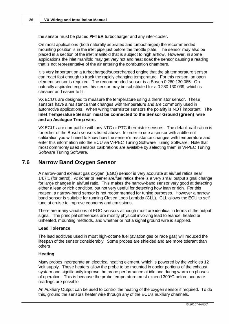
Using an inlet air temperature sensor allows fuel and ignition corrections to be made forchanges in the temperature of the air entering the engine. The air temperature sensor mustbe set-up to most accurately measure the temperature of the air entering the enginescombustion chambers. On a naturally aspirated engine this normally means any positionbetween the air filter and inlet manifold. However, on a turbocharged/supercharged engine
VX Wiring and Installation Manual26
© 2010 Vi-PEC
the sensor must be placed AFTER turbocharger and any inter-cooler.
On most applications (both naturally aspirated and turbocharged) the recommendedmounting position is in the inlet pipe just before the throttle plate. The sensor may also beplaced in a section of the inlet manifold that is subject to high airflow. However, in someapplications the inlet manifold may get very hot and heat soak the sensor causing a readingthat is not representative of the air entering the combustion chambers.
It is very important on a turbocharged/supercharged engine that the air temperature sensorcan react fast enough to track the rapidly changing temperature. For this reason, an openelement sensor is required. The recommended sensor is a Bosch 0 280 130 085. Onnaturally aspirated engines this sensor may be substituted for a 0 280 130 039, which ischeaper and easier to fit.
VX ECU's are designed to measure the temperature using a thermistor sensor. Thesesensors have a resistance that changes with temperature and are commonly used inautomotive applications. When wiring thermistor sensors the polarity is NOT important. TheInlet Temperature Sensor must be connected to the Sensor Ground (green) wireand an Analogue Temp wire.
VX ECU's are compatible with any NTC or PTC thermistor sensors. The default calibration isfor either of the Bosch sensors listed above. In order to use a sensor with a differentcalibration you will need to know how the sensor’s resistance changes with temperature andenter this information into the ECU via Vi-PEC Tuning Software Tuning Software. Note thatmost commonly used sensors calibrations are available by selecting them in Vi-PEC TuningSoftware Tuning Software.
7.6 Narrow Band Oxygen Sensor
A narrow-band exhaust gas oxygen (EGO) sensor is very accurate at air/fuel ratios near14.7:1 (for petrol). At richer or leaner are/fuel ratios there is a very small output signal changefor large changes in air/fuel ratio. This makes the narrow-band sensor very good at detectingeither a lean or rich condition, but not very useful for detecting how lean or rich. For thisreason, a narrow-band sensor is not recommended for tuning purposes. However a narrowband sensor is suitable for running Closed Loop Lambda (CLL). CLL allows the ECU to selftune at cruise to improve economy and emissions.
There are many variations of EGO sensors although most are identical in terms of the outputsignal. The principal differences are mostly physical involving lead tolerance, heated orunheated, mounting methods, and whether or not a signal ground wire is supplied.
Lead Tolerance
The lead additives used in most high-octane fuel (aviation gas or race gas) will reduced thelifespan of the sensor considerably. Some probes are shielded and are more tolerant thanothers.
Heating
Many probes incorporate an electrical heating element, which is powered by the vehicles 12Volt supply. These heaters allow the probe to be mounted in cooler portions of the exhaustsystem and significantly improve the probe performance at idle and during warm up phasesof operation. This is because the probe temperature must exceed 300ºC before accuratereadings are possible.
An Auxiliary Output can be used to control the heating of the oxygen sensor if required. To dothis, ground the sensors heater wire through any of the ECU's auxiliary channels.

Input Signal Wiring 27
© 2010 Vi-PEC
Mounting
Most probes have an M18 x 1.5 metric thread designed to screw into a mating boss. Somevariants use a bolted flange arrangement, but these are relatively uncommon.
Almost all EFI engines will have a probe installed as original equipment in the exhaustmanifold or turbo housing.
If the vehicle does not have a factory fitted EGO sensor, it will be necessary to manufacture asensor mount according to engine type and layout.
The ideal mounting position of the sensor in the exhaust can vary depending on theapplication. Most of the time the preferred position is in the exhaust manifold collector on anaturally aspirated engine or after the turbocharger on a turbocharged engine. However, alocation further down the exhaust is acceptable provided the probe is adequately heated. Note that it is also possible to get an EGO sensor too hot which also causes an inaccuratereading. Therefore in applications with particularly high exhaust gas temperatures (e.g. turboengines, rotary engines) it may be necessary to either use an unheated sensor or move aheated sensor further down the exhaust.
Caution: EGO sensors use ceramic material internally and are susceptible to impactdamage. Handle probes carefully to avoid impacts at all times.
Narrow Band Oxygen Sensor Wiring
Typically narrow-band EGO sensors can be recognised as having one, two, three or fourwires. These have the following functions.
Single Wire Sensor - The wire is the signal output and should be connected directly toan Analogue Voltage Input.
Two Wire Sensor - One wire for the signal output (to Analogue Voltage Input). Theother is the signal ground (Signal Ground (green)).
Three Wire Sensor (Heated) - One wire for the signal output (to Analogue VoltageInput). Two wires for the heater. One of the heater wires should be connected to anignition switched 12V supply. The other heater wire can be connected to a convenientground (or controlled using an auxiliary output). Heater polarity is not important.
Four Wire Sensor (Heated) - As for three wire sensor, but with an extra wire for thesignal ground which must be connected to Sensor Ground (green).
Recommended Narrow Band Oxygen Sensor
The recommended narrow-band EGO sensor is a Bosch 3-wire lead-tolerant unit with PartNumber 0 258 003 070. As with other Bosch 3 wire sensors, the wire colours are:
2 white wires = heater (18 watts)
1 black wire = output signal
7.7 Wide Band Oxygen Sensor
Wideband exhaust gas oxygen (EGO) sensors are able to accurately measure air/fuel ratiosover a very wide range from very lean to very rich. This makes these devices very suitablefor tuning purposes.
A wideband sensor can be used to run Closed Loop Lambda (CLL) for improved economyand emission. A wideband sensor is a necessity if Quick Tune (refer to the Vi-PEC Tuning

VX Wiring and Installation Manual28
© 2010 Vi-PEC
Software Tuning Software online help) is going to be used to tune the engine.
Any Analogue Volt channel may be used to accept the signal from a wide-band EGO sensorcontroller. Note that VX ECU's cannot accept the signal directly from a wide-band sensor. Awide-band controller works as an interface between a wide-band O2 sensor and the ECU. The controller should connect directly to the sensor and output a voltage between 0 and 5V.
The sensor calibration (the voltages that correspond to given air/fuel ratios) must be knownand this information must be entered into the ECU via Vi-PEC Tuning Software TuningSoftware.
The recommended Wideband Oxygen Sensor controller is the Innovate LC-1 Wide-Bandcontroller
7.8 GP Pressure & Temperature Sensing
Any Analogue Volt channel may be used as inputs from additional general purpose (GP)pressure and temperature sensors. The only restriction is that the sensor must have a 0-5Voutput. The sensor calibration (the voltages that correspond to given pressures/temperatures) must be known and this information must be entered into the ECU via Vi-PECTuning Software Tuning Software.
GP Pressure and Temperature Sensor Wiring:
Signal – Analogue Volt Channel
Power – As per sensor manufacturers specification (can use ECU's +5V out ifrequired)Ground – Ground to ECU's Sensor Ground.
Spare Analog Temperature channels can be used for wiring of additional NTC temperaturesenors. Refer to the wiring instructions for Engine Coolant Temperature sensors.
CAUTION!
Do not use a sensor designed to measure air pressure to measurefuel, oil or water pressures. Consult the sensor manufacturers
specifications.
7.9 Digital Input Wiring
Digital inputs may be connected to switches, controllers or sensors to control variousfunctions including launch control (clutch switch), anti-lag, high/low boost, water spray, dualfuel/ignition maps, nitrous oxide, air conditioning request and variable valve timing.
Switches and Controllers
The diagrams below show the two methods of wiring Digital Inputs to a switch. When wiringother devices such as controllers it will be necessary to determine if these devices are activelow or active high. If a switch or controller drives low then the Digital Inputs 'Pull-up Resister'will need to be enabled in Vi-PEC Tuning Software Tuning Software.

Input Signal Wiring 29
© 2010 Vi-PEC
Wiring of a Drive Low Switch to a Digital Input
Wiring of a Drive High Switch to a Digital Input
Vehicle Speed Input
Speed signals should only be connected to Digital Inputs 1 to 6.
Vehicle Speed may be calculated using the output from a digital speedometer drive or insome cases from the speedometer assembly itself. This may be connected directly to aDigital Input. Some sensors will require that the Digital Inputs 'Pull-up Resister' is enabled inVi-PEC Tuning Software Tuning Software.
VVT Cam Position Input
Continuously Variable Valve Timing (CVVT, VVT, VVTi, AVCS) Cam Position digital inputs canonly be connected to Digital Inputs 1 to 4.
Reluctor or Optical/Hall sensors can be used to measure camshaft position on enginesequipped with VVT systems. VVT position sensors should be wired to digital Inputs in thesame manner as Trigger Sensors. This includes the use of Sensor ground and shieldedcables. Shielded cable for Digital Input wiring is not included in the standard loom but can bepurchased from your Vi-PEC dealer. Not using shielded cable can result in cam shaftposition measurement errors.
For engine specific information on the wiring of triggers and VVT position sensors refer toyour Vi-PEC dealer or www.Vi-PEC.com.
Although not absolutely necessary, it is recommended to ease configuration that camposition signals are wired to the same number Digital Input channel as the correspondingsolenoid control Auxiliary Output (refer following table). For compatibility, the following use ofDigital Inputs and Auxiliary outputs is recommended for VVT wiring. Note that in practice anyDigital Input/Auxiliary Output combination can be used.

VX Wiring and Installation Manual30
© 2010 Vi-PEC
Cam Shaft Digital Input Auxiliary Output
Inlet or Inlet LH DI 1 Aux 1
Inlet RH DI 2 Aux 2
Exhaust or Exhaust LH DI 3 Aux 3
Exhaust RH DI 4 Aux 4
In cases where the same camshaft position signal is used to measure camshaft timing aswell as provide sync (firing order position) information, this sensor will usually be wired toTrigger 2.
8 Output Wiring
The following sections describe wiring of output devices to VX ECU's.
8.1 Fuel Injector Drives
Note: For information on wiring Injection Outputs as additional Auxiliary Outputs, refer to thesection on wiring Auxiliary Outputs.
The injector drives on a VX ECUs work by supplying an EARTH to turn the injectors on. Aswitched (key ON) 12V must be supplied to the other terminal of the injector. The polarity ofthe injector is not important. Note that injectors should be powered from the same supply asthe ECU. This ensures the ECU has accurate measurement of injector voltage forcalculating injector dead time.
WARNING!
DO NOT connect +12V directly to any of the injector drives
Injectors are commonly available as either high impedance or low impedance. To determineinjector impedance: With the injector unplugged, use an ohmmeter to measure theresistance across the two terminals of the injector;
If the injector resistance is greater than 6 Ω then the injectors are high impedance andno ballast resistors are required,If the injector resistance is less than 6 Ω then ballast resistors will be required.
8.1.1 High Impedance Injectors
All VX ECU's can drive up to two high impedance injectors off each Injector Drive. It isrecommended to wire a single injector to each injector drive. On engines with more cylindersthan the ECU has Injection Drives injectors should be paired.
Wiring for high impedance injectors is shown below.

Output Wiring 31
© 2010 Vi-PEC
High Impedance Injector Wiring
8.1.2 Low Impedance Injectors
V88 ECUs can drive low impedance injectors directly the same as wiring high impedanceinjectors. When driving low impedance injectors directly it is essential that before running theengine the correct Injection Mode (Peak and Hold) and Peak and Hold Currents areconfigured using Vi-PEC Tuning Software Tuning Software.
V44 ECUs have saturated injection drivers only. This means that:
WARNING!
Low impedance injectors can NOT be wired directly to a V44 ECU.
To use a V44 on an engine equipped with low impedance injectors, ballast resisters must beinstalled. Note that most vehicles factory fitted with low impedance injectors will have factoryfitted ballast resisters.
Wiring Ballast Resistors
V44 ECUs can drive up to 2 low impedance injectors on one Injection Drive WITH BALLASTRESISTORS FITTED. Ballast resistors must be used to limit the current through theinjectors and injector drive to avoid damage.
It is recommended to wire a single injector to each injector drive. On engines with more thaneight cylinders injectors should be paired.
Injector wiring for injectors with ballast resistors
Ballast Resistor Selection
VX Wiring and Installation Manual32
© 2010 Vi-PEC
If the injector impedance is LESS THAN 2 Ohms, use 2R2 (2.2 Ohm) ballast.
If the injector impedance is between 2 and 6 Ohms, use 4R7 (4.7 Ohm) ballast.
If the injector impedance is greater than 6 Ohms, use no ballast.
It should be noted that injector ballast resistors get quite hot at high injector duty cycles. Therefore these should be mounted on a heat sink and this should be bolted to the chassis. Typically ballast resistors should be mounted in the engine bay.
Do not use common 0.25W or 1.0W resistors, as these will burn out almost immediately. 50W resistors should be used. These are relatively uncommon at hobbyist shops, but arereadily available from your Vi-PEC dealer in groups of 2, 4, 6 or 8 resistors on a heat sink.
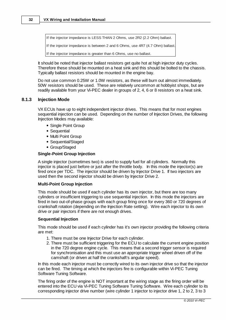
8.1.3 Injection Mode
VX ECUs have up to eight independent injector drives. This means that for most enginessequential injection can be used. Depending on the number of Injection Drives, the followingInjection Modes may available:
Single Point Group
Sequential
Multi Point Group
Sequential/Staged
Group/Staged
Single-Point Group Injection
A single injector (sometimes two) is used to supply fuel for all cylinders. Normally thisinjector is placed just before or just after the throttle body. In this mode the injector(s) arefired once per TDC. The injector should be driven by Injector Drive 1. If two injectors areused then the second injector should be driven by Injector Drive 2.
Multi-Point Group Injection
This mode should be used if each cylinder has its own injector, but there are too manycylinders or insufficient triggering to use sequential injection. In this mode the injectors arefired in two out-of-phase groups with each group firing once for every 360 or 720 degrees ofcrankshaft rotation (depending on the Injection Rate setting). Wire each injector to its owndrive or pair injectors if there are not enough drives.
Sequential Injection
This mode should be used if each cylinder has it’s own injector providing the following criteriaare met:
1. There must be one Injector Drive for each cylinder.2. There must be sufficient triggering for the ECU to calculate the current engine position
in the 720 degree engine cycle. This means that a second trigger sensor is requiredfor synchronisation and this must use an appropriate trigger wheel driven off of thecamshaft (or driven at half the crankshaft’s angular speed).
In this mode each injector must be correctly wired to its own injector drive so that the injectorcan be fired. The timing at which the injectors fire is configurable within Vi-PEC TuningSoftware Tuning Software.
The firing order of the engine is NOT important at the wiring stage as the firing order will beentered into the ECU via Vi-PEC Tuning Software Tuning Software. Wire each cylinder to itscorresponding injector drive number (wire cylinder 1 injector to injector drive 1, 2 to 2, 3 to 3

Output Wiring 33
© 2010 Vi-PEC
etc...).
Set the 'Injection Mode' to 'Sequential' when using this configuration.
Staged Injection
This mode allows the use of staged injection where the engine uses primary injectors thatoperate at all times and secondary injectors that only operate at high load/rpm. Thisarrangement is useful in applications with very high fuel delivery requirements that wouldnormally require extremely large injectors. Very large injectors make tuning difficult at lowloads (idle and low power operation). With staged injection one smaller set of injectorsoperates at low load giving more precise control. At higher loads both sets of injectorsbecome active to supply the required fuelling needs.
Group Fire Staged Injection
This mode must be used for staged injection if the criteria required for sequential injection arenot met. In this mode the number of injection drives used can be specified using the 'ActiveDrives' setting. Irrespective of the number of injection drives used, wire the primary injectorsto odd numbered Injector Drives (Inj1, Inj3, Inj5, Inj7), wire the secondary injectors to evennumbered Injector Drives (Inj2, Inj4, Inj6, Inj8). In this mode all primary injector drives are firedat the same time (group fire) and all secondary injector drives are fired at the same time(group fire). Set the 'Injection Mode' to 'Group/Staged' when using this configuration.
Sequential Staged Injection (V88 only)
This mode can be used to provide full sequential injection on both the primary and secondaryinjectors. This mode requires that the engine have sufficient triggering to calculate crankshaftposition and the position in the firing order (i.e. a sync signal is required).
Cylinders/Rotors
Primary Secondary Spare Inj Drives
2 Inj 1 = Pri 1Inj 2 = Pri 2
Inj 3 = Sec 1Inj 4 = Sec 2
Inj 5-8 Spare
3 Inj 1 = Pri 1Inj 2 = Pri 2Inj 3 = Pri 3
Inj 4 = Sec 1Inj 5 = Sec 2Inj 6 = Sec 3
Inj 7-8 Spare
4 Inj 1 = Pri 1Inj 2 = Pri 2Inj 3 = Pri 3Inj 4 = Pri 4
Inj 5 = Sec 1Inj 6 = Sec 2Inj 7 = Sec 3Inj 8 = Sec 4
None
5 Inj 1 = Pri 1Inj 2 = Pri 2Inj 3 = Pri 3Inj 4 = Pri 4Inj 5 = Pri 5
Inj 7 = Sec Group 1Inj 8 = Sec Group 2
Inj 6 Spare
6 Inj 1 = Pri 1Inj 2 = Pri 2Inj 3 = Pri 3Inj 4 = Pri 4Inj 5 = Pri 5Inj 6 = Pri 6
Inj 7 = Sec Group 1Inj 8 = Sec Group 2
None
Full primary and secondary sequential injection can only be achieved on engines with four

VX Wiring and Installation Manual34
© 2010 Vi-PEC
cylinders or less. Wire injectors as shown in the preceding table. On engines with 5 or 6cylinders the primary injectors will be fired sequentially and secondary injectors fired in groupmode. Engines with 8 or more cylinders must use Group Staged Injection.
Set the 'Injection Mode' to 'Sequential/Staged' when using this configuration.
8.2 Ignition Drives
Note: For information on wiring Ignition Outputs as additional Auxiliary Outputs, refer to thesection on wiring Auxiliary Outputs.
VX ECU's have up to 8 independent ignition drives which can be used in a wide range ofconfigurations from a basic distributor set-up through to more complex multi-coilarrangements. VX ECU's support the ignition configurations shown in table below.
Number ofCylinders
DistributorWasted Spark (1Dual Post Coil per
two Cylinders)
Direct Spark (1 Coil perCylinder)
2
3
4
5 *
6 *
8 * *
10 *
12 *
Available Ignition Combinations (* V88 ECU Only)
8.2.1 Igniter Requirements
An igniter acts as an interface between the ECU and the ignition coil(s). The Igniter is used todrive the coil(s) by supplying a ground for the coils negative terminal. Wiring of an igniter andcoil is shown below.
PICTURE - figure 8.3
Wiring of igniter and coil
The igniter is basically a solid-state switch, which may also limit the coil current to apredetermined value. This limiting feature eliminates coil ballast resistors and providesprotection of the coils if the dwell time (time the coil is charged for) is set too long. Overvoltage clamping is incorporated to prevent damage to the igniter should a high-tension leadbecome disconnected or similar.
Each one of the ignition drives may be used to switch a separate channel on an igniter. Eachchannel on the igniter is used to switch an ignition coil. The following examples show therequirements for some common ignition configurations:
Example - 4 cylinder engine with direct spark
Four ignition drives must be used
A four channel igniter (or 2 x 2 channel igniter's) must be used

Output Wiring 35
© 2010 Vi-PEC
Four Single Post Coils must be used
Example - 4 cylinder engine with wasted spark
Only two ignition drives are used (Ign. 1 and Ign. 2)
One two channel igniter must be used
Two Dual Post Coils must be used
Example - Engine with single distributor ignition
Only one ignition drive is used (Ign. 1)
A single channel igniter must be used
One Single Post Coil must be used
Conventional igniters begin to charge the coil when their input is high. Spark occurs when theinput goes low. This is known as a Rising 'Dwell Edge'. Some factory igniters (eg someFord and Honda), MSD ignitions and some other units work in the opposite sense. The coilbegins to charge when the input signal goes low while spark occurs on the transition from lowto high. In these cases, a Falling 'Dwell Edge' must be selected in Vi-PEC Tuning SoftwareTuning Software.
Always mount igniter(s) in the engine bay as close to the ignition coil(s) as possible. Thishelps to minimize the length of high current wiring between the igniter(s) and coil(s).
WARNING!
NEVER mount the igniter(s) on or near to the VX ECU
Avoid areas of high temperature such as exhausts, turbo chargers and radiators since theigniter itself will generate heat at high power. If vibration levels will be excessively high, someform of soft or rubber mounting is advisable to prevent component and wiring fatigue.
High current ignition wiring should NOT be run along side other ECU wiring. Separate highcurrent ignition wiring into its own loom running directly to the coils.
8.2.2 Coil Requirements
The coil required for a particular application will depend largely on the method used to drivethe coil and the spark energy requirements. Consult the igniter manufacturer for arecommended coil for use with a particular igniter.
The required Dwell Time will be entirely dependent on the coils inductance. Dwell timeshould be correctly set to avoid damage to coils and igniters and also ensure adequate sparkenergy. It is not true that increased dwell time will always result in increased spark energy.
Use only coils designed for high-energy transistor/inductive ignition systems. The coilsprimary resistance should typically be between 0.4 Ω and 1.0 Ω. This applies to both singleand dual post coils in distributed and multi coil applications.
8.2.3 Ignition System Wiring
The following guidelines should be considered when wiring ignition systems:
Unsuppressed H.T. leads act as aerials and radiate very powerful interference signals. ALL applications must use suppressed HT leads, preferably resistance type ratherthan spiral wound or inductive. Typically these vary from 1000 ohms to 5000 ohmsdepending on lead length. NEVER use plain wire leads.
ALL applications must also employ a suppressor capacitor (0.5 - 3uF) connected

VX Wiring and Installation Manual36
© 2010 Vi-PEC
directly between the ignition coil(s) POSITIVE terminal and ground. Most pointscondensers are suitable. Multiple coils can share a single suppressor. ‘V’ and boxerengines with multiple coils must have a suppressor on each bank.
Isolate the ignition system as much as possible from other sensitive devices, especiallythe ECU. Do not run non-ignition related wiring close to igniters, coils or HT leadswherever possible. Maintain maximum distance from radio transmitters and coaxialcables etc.
Always use resistor spark plugs. These can be checked by measuring the resistancebetween the top of the spark plug and the centre electrode. On a resistor plug theresistance will be several thousand ohms.
If insufficient ignition energy is causing a high-power misfire (especially on turbo/supercharged engines), it may be necessary to reduce the spark plug gap. Gaps as small as0.5mm (.020') may be necessary. This also reduces the amount of radiated electricalnoise due to the lower firing voltage.
Keep the input wiring to the igniter (from the ECU) separate from the output wiring of theigniter (to the coils) as shown below.
Igniter
Signals from ECU Outputs to Coils
Note:- Separate Sensitive Signal wires from Coil Wires- Ground ignitor to engine block (keep wiring short)
Separation of igniter input and output wiring
8.2.4 Distributor Ignition
A distributor rotates at half the crankshaft speed and routes the high voltage generated by thecoil to the intended spark plug via a rotor and HT wiring. A distributed engine requires oneignition drive and a single channel igniter. Use Ignition Drive 1 to switch the igniter.
Because the rotor will only point to each post on the distributor cap for a short amount oftime, the rotor timing dictates the range of ignition advance angles that may be used withoutmisfiring or unnecessarily losing spark energy. A wider tip on the rotor will also allow a widerrange of timing values to be used. The tip of rotor should be just leaving the post when thecrankshaft is positioned at the minimum timing that will be used (typically at about 10 degreesBTDC). The point where the leading tip of the rotor arrives at the post is the most advancedtiming that should be used.

Output Wiring 37
© 2010 Vi-PEC
Correct Rotor Timing
8.2.5 Multi-Coil Wasted Spark Ignition
Wasted spark will fire two cylinders simultaneously, using a common dual post coil. When adual post coil is fired, two cylinders receive a spark. One cylinder is fired conventionally onthe compression stroke while the other cylinder has its piston in the same position but on theexhaust stroke. One crankshaft rotation later, these two cylinders are two working stokesfurther ahead and the spark plugs fire again, but now with reversed roles. The result is thateach coil will be fired twice per engine cycle hence the term “wasted spark”. This set-up canONLY be used on engines with an even number of cylinders.
Dual Post Coils
One dual post coil (with a primary resistance between 0.4 and 1.0 ohms) is required per 2cylinders. Figure 8.8 shows a typical coil. The coils should be positioned so they minimise thelength of the HT Leads. This will help reduce the electrical noise generated when the sparkplugs are fired.
Dual Post Coil
The main concern when using dual post coils is the generation of electrical interference. Thiscan interfere with ECU operation and cause unwanted static on car radios. The ignitionsuppression techniques outlined earlier are particularly important. All wasted spark systemsshould use ‘Resistive Spark Plugs’ if the engine does not currently use them.
One igniter channel is required for each dual post coil.
Single Post Coils
It is possible to run an engine that has a single coil per cylinder in wasted spark configuration.

VX Wiring and Installation Manual38
© 2010 Vi-PEC
This is often done when there is not enough ignition drives to control each coil individually. Inthis case two coils are fired at the same time.
Each coil must be wired to a single igniter channel. It will be necessary to split the wiringfrom the each ECU ignition output to go to the input of two igniter channels.
IMPORTANT!
When running a wasted spark arrangement with a single coil percylinder, each coil must be wired to an individual ignition channel. DO
NOT wire the output of one igniter channel to two coils. This willresult in very low spark energy and erratic engine running.
Wasted Spark Ignition Wiring
To ensure each ignition drive is matched to the correct cylinder, the firing sequence will needto be determined. Note this option is only possible when the engine has an even number ofcylinders. When using a wasted spark arrangement, an ignition drive will fire cylinder pairsthat are 360° apart in the firing order.
Ignition Drive 1 always needs to be connected to cylinder number 1 and itscorresponding cylinder (360° apart in the firing order).
Ignition Drive 2 should be connected to the next cylinder in the firing order and itscorresponding cylinder (360° apart in the firing order).
If more cylinders exist (6, 8, 10 & 12 cylinder engines) then the pattern should becontinued. For example Ignition Drive 3 fires the third cylinder in the firing order and itscorresponding cylinder.
Use the following table to determine coil ignition wiring for wasted spark applications. Writethe engines firing order in the column on the left.
Write Firing Order Below Number of Cylinders
2 4 6 8
1 Ign 1 Ign 1 Ign 1 Ign 1
Ign 2 Ign 2 Ign 2 Ign 2
Ign 1 Ign 3 Ign 3
Ign 2 Ign 1 Ign 4
Ign 2 Ign 1
Ign 3 Ign 2
Ign 3
Ign 4
Wasted spark Ignition Wiring
Example - Wasted spark set-up for a 4 cylinder engine with 1-3-4-2 firing order.
Ignition Drive 1 fires cylinders 1 and 4
Ignition Drive 2 fires cylinders 2 and 3
Example - Wasted spark set-up for a 6 cylinder engine with 1-5-3-6-2-4 firing order.

Output Wiring 39
© 2010 Vi-PEC
Ignition Drive 1 fires cylinders 1 and 6
Ignition Drive 2 fires cylinders 5 and 2
Ignition Drive 3 fires cylinders 3 and 4
8.2.6 Multi-Coil Direct Spark Ignition
Direct spark uses an ignition coil per cylinder, firing each cylinder once per engine cycle (2crankshaft revolutions). If multi-coil operation is required for an odd number of cylinders, theonly option is to use an ignition coil per cylinder.
V88 ECU's have eight ignition drives allowing up to eight individual coils to be controlled. Therefore, this ECU may only be used on engines with eight cylinders or less with directspark ignition.
8.3 Auxiliary Output Wiring
VX ECUs have up to 10 auxiliary outputs. Unused ignition and injection channels can also beused as auxiliary outputs. Auxiliary outputs are general-purpose outputs that may be used toperform a wide range of functions. However, the following limitations apply:
All Auxiliary, Ignition and Injection outputs can switch a load by supplying a ground for it.
Aux 5 to 8 can be used as high side drives (ie they can supply power to a load).
A Three Terminal ISC Solenoid must be wired to Aux 1 and Aux 2.
An ISC Stepper Motor must be wired to Aux 5, Aux 6, Aux 7 and Aux 8.
Aux 5 to 8 and Ignition 1 to 4 when used as Aux channels can not be Pulse WidthModulated (PWM) above 300Hz (except in tacho mode). VVT Solenoids must be wired to Aux channels 1 to 4.
An Electronic Throttle Control Motor must be wired to Aux 9 and Aux 10.
Auxiliary Outputs are normally used to supply a GROUND to actuate solenoids, relays, LEDsor lights. The amount of current flow is entirely dependant on the internal resistance of thedevice connected to a drive. The load must not draw more than 2 Amps. This means that adirectly connected load should have a resistance exceeding 7Ω. If the resistance is lowerthan this a relay should be used. DO NOT connect +12V directly to any auxiliary output.
The following list shows only some of the devices that can be controlled by Auxiliary Outputs
Idle Speed control (ISC) Solenoids and Stepper Motors
Boost Control Solenoid
Fuel Pump Relay
Fuel Pump Speed controller
Engine Fan Relay
A/C Clutch Relay
A/C Fan Relay
Inter-cooler Spray Pump Relay
Tachometer
Check Engine Light
Purge and EGR Solenoids
Variable Valve Timing Solenoids
Speedometer
Oxygen Sensor Heater

VX Wiring and Installation Manual40
© 2010 Vi-PEC
Water Injection
Nitrous Oxide Injection
Electronic Throttle Control
General Purpose Switching
General Purpose Pulse Width Modulation (PWM)
8.3.1 Low Side Driving (Switching To Ground)
On a typical two-terminal solenoid, the Auxiliary Output should be connected to one terminalto supply a ground, while the other terminal should be connected to an ignition switched (keyON) 12V source. A warning/shift light may also be wired the same way. This configuration isshown below.
WARNING!
Solenoids and relays wired to auxiliary outputs must take theirswitching coil power supply from a switched (through a relay) source.Do NOT use a +12V hot supply (direct from the battery). Doing somay result in the ECU staying powered up when the key is switched
off.
Low Side Driving a Solenoid
8.3.2 High Side Driving (Switching Power Supply)
Some single terminal solenoids are grounded through the engine block (e.g. most HondaVTEC solenoids). Therefore power must be applied to the terminal on the solenoid to turn iton. Auxiliary Outputs 5 to 8 can be used to supply power to a solenoid. If Auxiliary Outputs 5to 8 are already used then it will be necessary to wire a relay to control the solenoids powersupply.
Aux 5 to 8 high side drivers can supply up to 0.5 Amps. this means the solenoid must have aresistance greater than 30 Ohms.

Output Wiring 41
© 2010 Vi-PEC
High Side Driving a Solenoid
8.3.3 Switching Through a Relay
To switch any large load through a relay, the wiring shown below should be used. Examplesof such loads include fuel pumps, engine coolant fans and air conditioning compressorclutches. DO NOT wire high current devices directly to the ECU.
Switching Loads Using a Relay
8.3.4 Switching an LED
Auxiliary outputs may be connected to a high intensity LED to provide a shift, or warning light.However, a 1kΩ (1000Ω) current limiting resistor is required to be placed in series with theLED. Failure to install the resistor will result in permanent failure of the LED. A bulb may alsobe used instead of an LED (and it does not require a resistor).

VX Wiring and Installation Manual42
© 2010 Vi-PEC
Connection of an LED to an Auxiliary Output
8.4 Idle Speed Control
Idle Speed Control (ISC) is required to provide an acceptable idle speed when the engine iscold or when loads (AC etc.) are applied. Without idle speed control, an engine will idle tooslowly when cold. Often the cold idle speed will be so low that the engine stalls. Likewise,extra load loads will decrease the idle speed and may cause the idle to stall or becomeunstable. The ISC system regulates the engine idle speed by adjusting the amount of airwhich is bypassed around the throttle. This air may be bypassed using either a solenoid orstepper motor.
VX ECU's employ a sophisticated closed loop idle speed control system that provides factorylike idle speed control. This system can be used to provide idle speed control using either a 2or 3 terminal ISC Solenoid or a 4 or 6 terminal ISC Stepper Motor. While a solenoid andstepper motor operate very differently they both achieve the effect of bypassing air around thethrottle plate to increase the idle speed.
Some engines use a non-electronic system to control idle speed as the engine warms up.This system contains a bimetallic strip, which is heated by the engine coolant and/orelectrically. As the engine warms up, the amount of bypassed air is reduced and the idle isreturned to its normal level. The ECU does not control this type of device. It is intendedONLY as an idle up when the engine is cold.
8.4.1 Two Terminal ISC Solenoid
A two terminal ISC solenoid may be wired to Auxiliary Channels 1 to 8. Injection channelscan not be used for ISC control. Ignition Channels 1 to 8 can also be used to control a twoterminal ISC Solenoid however an external fly-wheeling diode must be wired.
Two terminal ISC solenoids need only one auxiliary output (or ignition channel) to open thesolenoid. A spring is used to automatically close the solenoid. Connect one terminal to theengine managements power supply and connect the remaining terminal to an Auxiliary/Ignition Output Output. See Figure 8.13. The orientation of the wires does not matter.
An ISC solenoid must be wired to a switched power supply. Note that some Nissan ISCsolenoids are powered directly from the battery. This wiring must be changed,

Output Wiring 43
© 2010 Vi-PEC
Wiring for two-terminal ISC solenoid on Auxiliary Output
Wiring for two-terminal ISC solenoid on Ignition Output
8.4.2 Three Terminal ISC Solenoid
A Three Terminal ISC Solenoid must be wired to Aux 1 and Aux 2. Aux 1 is ISC Close, Aux 2is ISC Open.
Three terminal ISC solenoids needs one Auxiliary Output to open the solenoid and anotherAuxiliary Output to close it.
Use an ohmmeter to find the common terminal (usually the centre). Figure 8.14 shows theschematic. Next measure the resistance between the common and remaining two terminals.This should be greater than 10 ohms. Apply +12V to the common terminal of the solenoid. Ground one of the other terminals. If this terminal causes the valve to open, connect it to anAuxiliary Output 2 and note that this output should be configured as 'ISC Solenoid'. If thevalve closes, connect the terminal to Auxiliary Output 1 and note that this output should beconfigured as 'ISC Solenoid Slave'.

VX Wiring and Installation Manual44
© 2010 Vi-PEC
Three terminal ISC Solenoid Wiring
8.4.3 Four Terminal ISC Stepper Motor
An ISC Stepper Motor must be wired to Aux 5, Aux 6, Aux 7 and Aux 8.
When using an ISC Stepper, the ECUs power supply should be wired for ECU Hold Power asshown in Figure 6.2. This will allow the ECUs Hold Power function to be taken advantage of. Using ECU Hold Power allows the ECU to reset the stepper motor after key off. This avoidsextended cranking periods caused by resetting the stepper at key on.
The diagram below shows a schematic of a four-terminal stepper motor. Note that there aretwo coils. Use an ohmmeter to pair the terminals with a common coil. Aux 5 and 6 must beconnected to the terminals for one coil, while Aux 7 and 8 must be connected to the terminalsfor the other coil. If it is found that the stepper motor runs in the opposite direction to thatexpected, reverse the wiring to Aux 5 and Aux 6.
Four-terminal ISC Stepper Motor

Output Wiring 45
© 2010 Vi-PEC
8.4.4 Six Terminal ISC Stepper Motor
An ISC Stepper Motor must be wired to Aux 5, Aux 6, Aux 7 and Aux 8.
When using an ISC Stepper, the ECUs power supply should be wired for ECU Hold Power. This will allow the ECUs Hold Power function to be taken advantage of. Using ECU HoldPower allows the ECU to reset the stepper motor after key off. This avoids extendedcranking periods caused by resetting the stepper at key on.
The diagram below shows a schematic of a six-terminal stepper motor. These are similar toa four-terminal Stepper Motor, but each coil has a centre-tap that must be connected to 12V. Like the four-terminal version, Aux 5 and 6 must be connected to the terminals for one coil,while Aux 7 and 8 must be connected to the terminals for the other coil. If it is found that thestepper motor runs in the opposite direction to that expected, reverse the wiring to Aux 5 andAux 6 channels.
Six-terminal ISC Stepper Motor
8.5 Tachometer
An auxiliary output configured as 'Tacho' produces a 0-12V pulse to drive a low-leveltachometer. There will be one output pulse for each time a cylinder reaches TDC. Connectan Auxiliary Output directly to a low-level tachometer.
VX ECUs will NOT drive a high-level tachometer. High-level tachometers must be triggeredby a coil’s negative terminal. Using a high-level tachometer on a multi-coil engine presentssome problems, as each coil is not firing as often as a distributor engine’s coil would. In thiscase the preferred solution is to modify the high-level tachometer to accept a low-level signal.
8.6 Variable Valve Timing (VVT) Solenoids
Continuously Variable Valve timing (CVVT, VVT, VVTi, AVCS) Cam Position solenoids canonly be connected to Auxiliary Outputs 1 to 4.

VX Wiring and Installation Manual46
© 2010 Vi-PEC
It is recommended to ease configuration that cam position control solenoids are wired to thesame number Auxiliary Output channel as the corresponding cam position Digital Input (referfollowing example).
Although not absolutely necessary, it is recommended to ease configuration that camposition signals are wired to the same number Digital Input channel as the correspondingsolenoid control Auxiliary Output (refer following table).
For compatibility, the following use of Digital Inputs and Auxiliary outputs is recommended forVVT wiring. Note that in practice any Digital Input/Auxiliary Output combination can be used.
Cam Shaft Digital Input Auxiliary Output
Inlet or Inlet LH DI 1 Aux 1
Inlet RH DI 2 Aux 2
Exhaust or Exhaust LH DI 3 Aux 3
Exhaust RH DI 4 Aux 4
Solenoids MUST be wired directly to an auxiliary output channel DO NOT wire continuouslyvariable valve timing solenoids through a relay as high frequency switching is used.
Some factory systems use 12V switching to control VVT solenoids. These solenoids mustbe rewired to be ground switching.
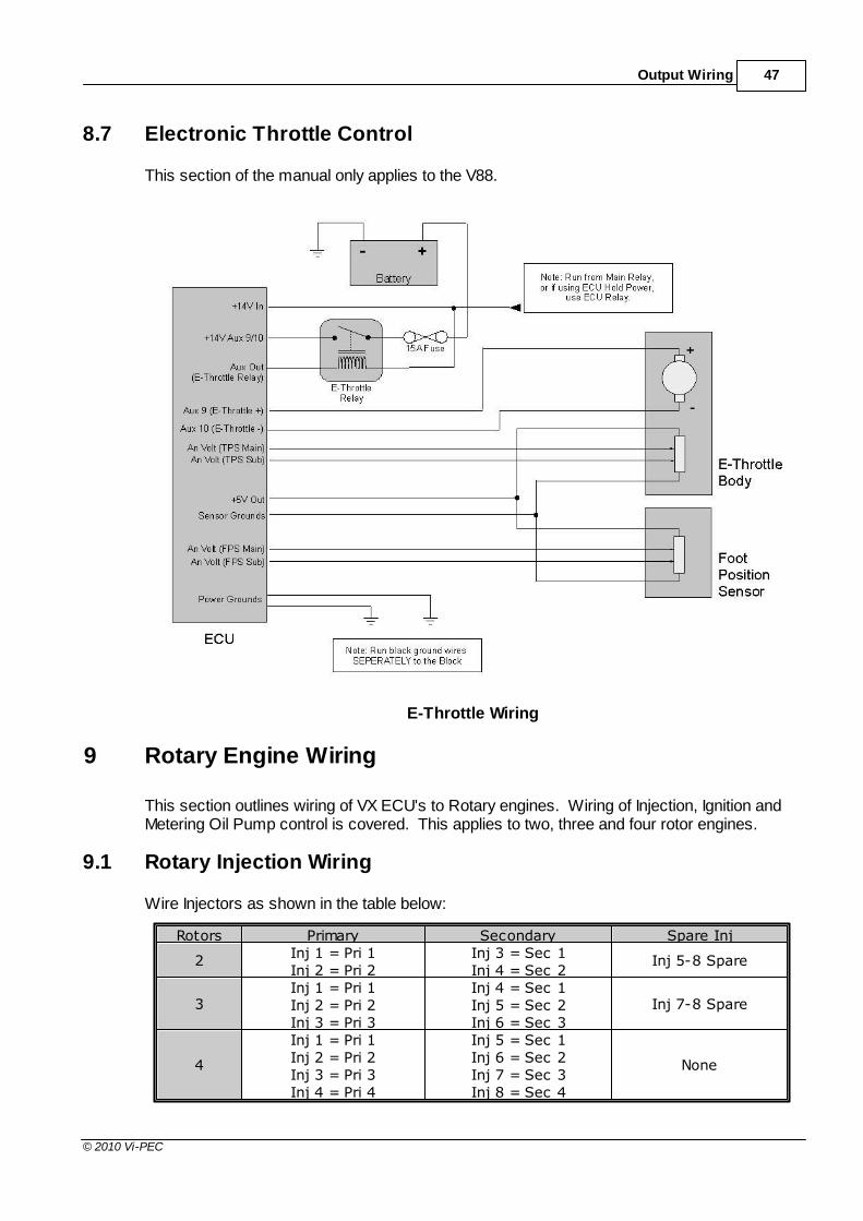
Output Wiring 47
© 2010 Vi-PEC
8.7 Electronic Throttle Control
This section of the manual only applies to the V88.
E-Throttle Wiring
9 Rotary Engine Wiring
This section outlines wiring of VX ECU's to Rotary engines. Wiring of Injection, Ignition andMetering Oil Pump control is covered. This applies to two, three and four rotor engines.
9.1 Rotary Injection Wiring
Wire Injectors as shown in the table below:
Rotors Primary Secondary Spare Inj
2Inj 1 = Pri 1Inj 2 = Pri 2
Inj 3 = Sec 1Inj 4 = Sec 2
Inj 5-8 Spare
3Inj 1 = Pri 1Inj 2 = Pri 2Inj 3 = Pri 3
Inj 4 = Sec 1Inj 5 = Sec 2Inj 6 = Sec 3
Inj 7-8 Spare
4
Inj 1 = Pri 1Inj 2 = Pri 2Inj 3 = Pri 3Inj 4 = Pri 4
Inj 5 = Sec 1Inj 6 = Sec 2Inj 7 = Sec 3Inj 8 = Sec 4
None

VX Wiring and Installation Manual48
© 2010 Vi-PEC
Rotary Injection Wiring
Notes:
A V88 ECU is required for sequential injection on 3 and 4 rotor engines.
Injection mode should be set to Sequential/Staged.
Ensure injector staging adjustments and primary and secondary injector dead timesare is setup correctly for the injector types fitted.
V44 ECU's must be wired with ballast resistors if low impedance injectros are used.
When wiring low impedance injectors directly to a V88 ECU make sure Injector DriverMode is set to Peak and Hold and the correct peak and hold currents have been set.Spare Injection drives can be used as additional auxiliary outputs if required.
9.2 Rotary Ignition Wiring
Wire Ignition as shown in the following table:
Rotors Ignition Mode Leading Trailing Spare Ign
2 Leading Wasted Ign 1 = L1 & L2Ign 2 = T2Ign 3 = T1
Ign 4
2 Direct SparkIgn 1 = L1Ign 2 = L2
Ign 3 = T1Ign 4 = T2
Ign 5-8 Spare
3 Direct SparkIgn 1 = L1Ign 2 = L2Ign 3 = L3
Ign 4 = T1Ign 5 = T2Ign 6 = T3
Ign 7-8 Spare
4 Direct Spark
Ign 1 = L1Ign 2 = L2Ign 3 = L3Ign 4 = L4
Ign 5 = T1Ign 6 = T2Ign 7 = T3Ign 8 = T4
None
Rotary Ignition Wiring
Notes:
A V88 ECU is required for direct spark ignition on 3 and 4 rotor engines.
Ensure the Ignition Mode is set to Rotary – Direct or Rotary – Leading Wasted. Do notuse the generic Direct Spark or Wasted Spark modes.Igniters must be wired. Do not wire coils directly to the ECU.
Spare Ignition drives can be used as additional auxiliary outputs if required.
9.3 Metering Oil Pump Wiring
Rotary engines Metering Oil Pumps can be controled directly from VX ECU's. This involveswiring the pumps stepper motor and position feedback to the ECU.

Rotary Engine Wiring 49
© 2010 Vi-PEC
Metering Oil Pump Control Wiring
Notes for wiring the stepper motor:
The centre tap of both windings should be wired to the same power supply as the ECUto ensure correct flywheeling and to prevent backfeeding.One common pair of windings must be wired to Auxiliary Outputs 5 and 6. The otherpair must be wired to Auxiliary Ouputs 7 and 8.Auxiliary Outputs 5-8 must be set to “Rotary Oil Pump”.
Use the Stepper Calibration function (found under Aux 8) to test if the stepper is wiredcorrectly. Setting Stepper Calibration to Fully Closed should cause the motor to closethe valve (so no oil enters the engine). Likewise, setting Stepper Calibration to FullyOpen should cause the motor to completely open the valve. Once finished tested, setStepper Calibration to Off.If the motor rotates in the wrong direction swap the wiring of Aux 7 and Aux 8.
Notes for wiring the motor position feedback:
Any Analog Volt input can be used for the feedback position signal.
The sensor should be wired to the ECU's sensor ground (which is grounded at theECU) not directly to the engine.When wired correctly the position signal should have approximately 0.9V with the valvefully closed and 4.4V with the valve fully open (note that if this is opposite it can becompensated for using the analog inputs calibration).
Instructions for configuring and calibrating the ECU for Metering Oil Pump Control can befound in the Vi-PEC Tuning Software Tuning Software online help (search Metering OilPump). These must be followed exactly to ensure accurate oil metering. This MUST bedone before attempting to start the engine.
Your nearest Vi-PEC dealer can provide you with a factory metering oil pump controlcalibration table if required.
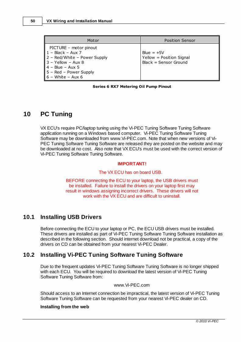
VX Wiring and Installation Manual50
© 2010 Vi-PEC
Motor Position Sensor
PICTURE - motor pinout1 – Black – Aux 72 – Red/White – Power Supply3 – Yellow – Aux 84 – Blue – Aux 55 – Red – Power Supply6 – White – Aux 6
Blue = +5VYellow = Position SignalBlack = Sensor Ground
Series 6 RX7 Metering Oil Pump Pinout
10 PC Tuning
VX ECU's require PC/laptop tuning using the Vi-PEC Tuning Software Tuning Softwareapplication running on a Windows based computer. Vi-PEC Tuning Software TuningSoftware may be downloaded from www.Vi-PEC.com. Note that when new versions of Vi-PEC Tuning Software Tuning Software are released they are posted on the website and maybe downloaded at no cost. Also note that VX ECU's must be used with the correct version ofVi-PEC Tuning Software Tuning Software.
IMPORTANT!
The VX ECU has on board USB.
BEFORE connecting the ECU to your laptop, the USB drivers mustbe installed. Failure to install the drivers on your laptop first may
result in windows assigning incorrect drivers. These drivers will notwork with the VX ECU and are difficult to uninstall.
10.1 Installing USB Drivers
Before connecting the ECU to your laptop or PC, the ECU USB drivers must be installed. These drivers are installed as part of Vi-PEC Tuning Software Tuning Software installation asdescribed in the following section. Should internet download not be practical, a copy of thedrivers on CD can be obtained from your nearest Vi-PEC Dealer.
10.2 Installing Vi-PEC Tuning Software Tuning Software
Due to the frequent updates Vi-PEC Tuning Software Tuning Software is no longer shippedwith each ECU. You will be required to download the latest version of Vi-PEC TuningSoftware Tuning Software from:
www.Vi-PEC.com
Should access to an Internet connection be impractical, the latest version of Vi-PEC TuningSoftware Tuning Software can be requested from your nearest Vi-PEC dealer on CD.
Installing from the web

PC Tuning 51
© 2010 Vi-PEC
1. Go to the above website and navigate to the downloads and software updates section.2. Download the latest version of Vi-PEC Tuning Software Tuning Software. When
prompted to run or save the file, select save. It is recommended to save this file onthe desktop.
3. Double click the saved file and follow on screen instructions.4. When prompted to install USB drivers, select yes. This may take some time.5. When installed, open Vi-PEC Tuning Software Tuning Software by double clicking on
the icon that has been placed on the desktop.
Installing from a CD
1. Insert the Vi-PEC Tuning Software Tuning Software disk into you computer’s CDROM.
2. Open 'My Computer'3. Double click your CD ROM drive.4. Double click the file labelled Vi-PEC Tuning Software Tuning SoftwareSetup.exe (or
similar name).5. Follow the on screen instructions.6. When prompted to install USB drivers, select yes. This may take some time.7. When installed, open Vi-PEC Tuning Software Tuning Software by double clicking on
the icon that has been placed on the desktop.
10.3 Communicating With Your ECU
After Vi-PEC Tuning Software Tuning Software installation, you will be able to connect the VXECU to the laptop to perform set-up and tuning work.
1. Connect the ECU to your laptop using a Vi-PEC VX ECU USB Cable. If not suppliedwith the ECU, these can be purchased from a Vi-PEC dealer. No other adapter orcabling is required. Connect the cable to the connector labelled USB.
2. If this is the first time you have connected a VX USB ECU to you laptop follow thedriver installation instructions that appear. When prompted if you wan to install driversselect 'Continue Anyway'.
3. Start Vi-PEC Tuning Software Tuning Software by double clicking on the Vi-PECTuning Software Tuning Software icon on the windows desktop.
4. Switch the key to the ON position. This will provide power to the ECU.5. In Vi-PEC Tuning Software Tuning Software, under the 'Options' menu, select
'Connection'. The connection options dialogue will open. Select the correct COM Portnumber from the drop down list or select auto for automatic com port detection.
6. Vi-PEC Tuning Software Tuning Software offers both mouse and keyboard control. Toestablish a connection between the PC and ECU using the mouse, click the ‘L’ iconlocated near the top centre of the Vi-PEC Tuning Software Tuning Software screen. Alternatively, using the keyboard, press and hold the Ctrl, Shift and L keys. The sameprocess can be used to disconnect. If a successful connection is established, Vi-PEC Tuning Software Tuning Software will download settings from the ECU,otherwise you will be warned that an error has occurred.
7. Make sure the connection shows “ONLINE” in the top right corner of Vi-PEC TuningSoftware Tuning Software. The logo should also be spinning in the top right corner.
8. To permanently STORE any changes made to the ECU click on the 'S' icon near thetop centre of the screen or press F4. If this is not done before turning the ECU'spower off all changes made will be lost.

VX Wiring and Installation Manual52
© 2010 Vi-PEC
11 First Time Setup
This section of the manual details a generic procedure for first time set-up of the VX ECU. These procedures also provide a good means of becoming familiar with both the VX ECUand Vi-PEC Tuning Software Tuning Software. It is recommended that these procedures arefollowed for every set-up, no matter how experienced you are!
11.1 Pre-start Checks
To avoid potential engine damage and wasted time, the adjustments presented in thefollowing sections must be made before attempting to start the engine.
For further help on any of the settings discussed below, consult the online Help in Vi-PECTuning Software Tuning Software. Online help can be invoked by pressing F1, or rightclicking any item and selecting ‘What’s this?’.
Pre-set-up Checks
Before attempting to configure the ECU, ensure the following tasks have been completed:
1. Ensure the ECU and all associated components are connected and correctly wired/installed.
2. Fully charge the vehicle’s battery, as the engine will be required to be cranked duringthe set-up procedure.
3. Check all oil and water levels are correct.
Connecting to Vi-PEC Tuning Software Tuning Software
Use the following procedure to establish a connection between your Vi-PEC ECU and Vi-PEC Tuning Software Tuning Software tuning software.
1. Make sure your laptop battery is fully charged or plugged in to mains power.2. Connect the ECU to your laptop and connect to Vi-PEC Tuning Software Tuning
Software as described in the 'Communicating with your ECU' section of this manual.
11.2 Initial Setup
After all checks described in previous sections have been performed, the ECU is ready to beconfigured for a particular application. The following set-up procedure should be used on allinstallations as a minimum:
Configuration and Fueling Set-up
If the ECU is to be used to control fuel injection, all of the following steps must be performed. If the ECU will not be controlling fuel injection, then only steps 1 and 2 are required.
1. If you have a .pcl file containing a baseconfiguration, this is the time to load it into theECU. To do this, select ‘Open’ form the ‘File’menu. Select the required .pcl file and then select‘Ok’. When prompted if you want to load the fileinto the ECU, select ‘Yes’.
2. Click on the ‘Configuration’ heading in the tuningfunction tree (top left of Vi-PEC Tuning SoftwareTuning Software screen):
a. Select the correct engine type

First Time Setup 53
© 2010 Vi-PEC
b. Select the correct number of cylinders/rotors.
c. Enter the engines firing order.
3. Click on the ‘Fuel’ heading, then ‘Fuel Set-up’:
a. Select the desired Injection Mode (e.g.Sequential or Group).
b. Select Injector Control method (e.g. Saturated orPeak and Hold) (V88 ECU only). Also set thecorrect injector peak and hold currents.
c. Set main fuel table load axis control parameter(e.g. MAP, MGP or TPS).
4. Click on ‘Accel Enrichment’:
a. Turn Accel Mode OFF for first time set-ups.
5. Click on ‘IAT Fuel Correction’:
a. If air temperature correction is to be used and anair temperature sensor is fitted, select therequired ‘IAT Mode’ (e.g. 2D Table or 3D Table).Note that the default 2D Table is recommendedfor the majority of applications.
b. Turn OFF air temp correction (under ‘IAT Mode’)if air temperature correction is not going to beused
6. Click on ‘Injector Deadtime':
a. Select the appropriate Injector Type. If therequired injector type is not listed, select theclosest type available. The injector dead timetable will be set up later when the engine isrunning.
7. Click on ‘Fuel Temp Correction’:
a. Set ‘Fuel Temp Mode’ to OFF if not required.
b. If fuel temperature correction is required and afuel temperature sensor has been fitted, set‘Fuel Temp Mode’ to the desired type.
8. Click on ‘Overrun Fuel Cut’:
a. Set ‘Fuel cut Mode’ to OFF.
9. Click on ‘Fuel Advanced’, then ‘Dual Fuel Table’:
a. Set 'Dual Table Mode' to OFF.
10.Click on ‘4D Fuel Table’:
a. Set ‘Fuel Overlay Mode’ to OFF.
11.Click on 'Injector Test';
a. Turn each injection channel on one by one andcheck that the correct cylinders injector clicks. Fix any problems now if the injectors do notoperate.
12.Perform a Store to permanently save changes tothe ECU by pressing F4.
Ignition Set-up
If the ECU is to be used to control ignition, all of the following steps must be performed. If the
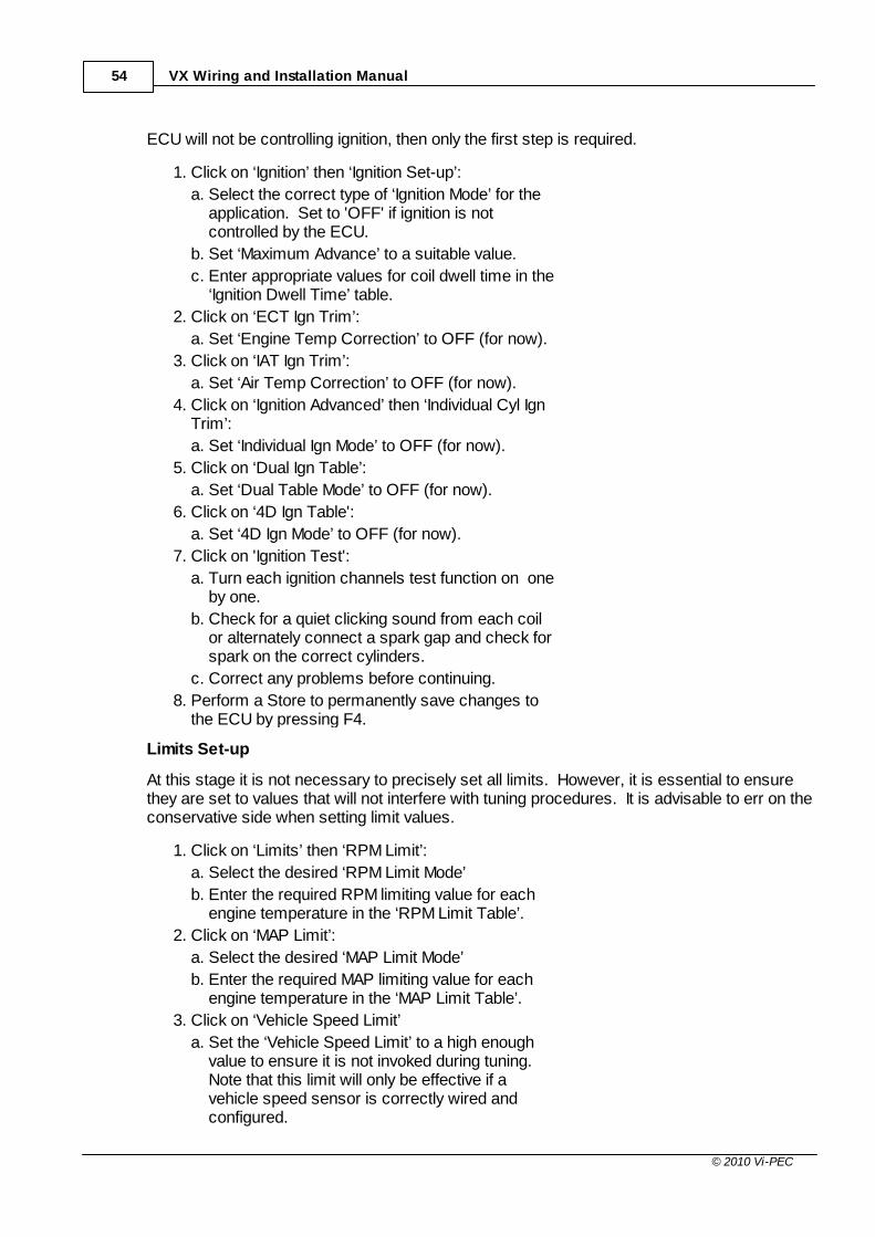
VX Wiring and Installation Manual54
© 2010 Vi-PEC
ECU will not be controlling ignition, then only the first step is required.
1. Click on ‘Ignition’ then ‘Ignition Set-up’:
a. Select the correct type of ‘Ignition Mode’ for theapplication. Set to 'OFF' if ignition is notcontrolled by the ECU.
b. Set ‘Maximum Advance’ to a suitable value.
c. Enter appropriate values for coil dwell time in the‘Ignition Dwell Time’ table.
2. Click on ‘ECT Ign Trim’:
a. Set ‘Engine Temp Correction’ to OFF (for now).
3. Click on ‘IAT Ign Trim’:
a. Set ‘Air Temp Correction’ to OFF (for now).
4. Click on ‘Ignition Advanced’ then ‘Individual Cyl IgnTrim’:
a. Set ‘Individual Ign Mode’ to OFF (for now).
5. Click on ‘Dual Ign Table’:
a. Set ‘Dual Table Mode’ to OFF (for now).
6. Click on ‘4D Ign Table':
a. Set ‘4D Ign Mode’ to OFF (for now).
7. Click on 'Ignition Test':
a. Turn each ignition channels test function on oneby one.
b. Check for a quiet clicking sound from each coilor alternately connect a spark gap and check forspark on the correct cylinders.
c. Correct any problems before continuing.
8. Perform a Store to permanently save changes tothe ECU by pressing F4.
Limits Set-up
At this stage it is not necessary to precisely set all limits. However, it is essential to ensurethey are set to values that will not interfere with tuning procedures. It is advisable to err on theconservative side when setting limit values.
1. Click on ‘Limits’ then ‘RPM Limit’:
a. Select the desired ‘RPM Limit Mode’
b. Enter the required RPM limiting value for eachengine temperature in the ‘RPM Limit Table’.
2. Click on ‘MAP Limit’:
a. Select the desired ‘MAP Limit Mode’
b. Enter the required MAP limiting value for eachengine temperature in the ‘MAP Limit Table’.
3. Click on ‘Vehicle Speed Limit’
a. Set the ‘Vehicle Speed Limit’ to a high enoughvalue to ensure it is not invoked during tuning. Note that this limit will only be effective if avehicle speed sensor is correctly wired andconfigured.

First Time Setup 55
© 2010 Vi-PEC
4. Perform a Store to permanently save changes tothe ECU by pressing F4.
Auxiliary Output Set-up
This section configures the ECU’s Auxiliary Output drivers for the devices they have beenwired to. Preparing a configuration table as shown in Section 2.7 of this manual will greatlysimplify set-up of Auxiliary Outputs. Note that one auxiliary channel should always be wiredand configured for the fuel pump relay drive.
1. Click on ‘Auxiliary Outputs’ then select the firstAuxiliary Output that requires configuration:
a. Select the required ‘Function’ for the AuxiliaryOutput channel.
b. Configure the channel as required. Refer to Vi-PEC Tuning Software Tuning Software’s onlinehelp for more information on adjustments.
2. Configure each additional Auxiliary Output channel. Ensure unused channels have their ‘Function’ setto ‘Not Selected’. Note that the ‘Test On’ and 'TestPWM' functions can be used to test wiring ofauxiliary output devices.
3. Configure any Ignition and Injection channels usedfor auxiliary output functions in the same manner.
4. Perform a Store to permanently save changes tothe ECU by pressing F4.
Digital Input Set-up
This section configures the ECU's Digital Input channels for the devices they have been wiredto. Preparing a configuration table as shown in Section 2.7 will greatly simplify set-up ofDigital Inputs.
1. Click on ‘Digital Inputs’ then select the first DigitalInput that requires configuration:
a. Select the required ‘Function’ for the Digital Inputchannel.
b. Configure the channel as required. Refer to Vi-PEC Tuning Software Tuning Software’s onlinehelp for more information on adjustments.
c. Confirm the operation of the Digital Input byopening the Digital Inputs tab of the runtimevalues (lower area of Vi-PEC Tuning SoftwareTuning Software screen).
2. Configure each additional Digital Input channel. Ensure unused channels have their ‘Function’ setto ‘OFF’.
3. Perform a Store to permanently save changes tothe ECU by pressing F4.
Analogue Input Set-up
This section configures the ECU’s Analogue Input channels for the devices they have beenwired to. Preparing a configuration table as shown in Section 2.7 will greatly simplify set-up

VX Wiring and Installation Manual56
© 2010 Vi-PEC
of Analogue Inputs. Essential inputs are configured in this section. All steps must beperformed on all applications.
1. Click on ‘Analogue Channel’.
2. Select the Analogue Channel that is wired to theMAP sensor.
a. Set the function to ‘MAP Sensor’.
b. Select the correct “MAP Sensor Type’.
c. Ensure the MAP runtime value reads reasonablyclose to the barometric pressure reading (BAP).
d. Perform a MAP Sensor Calibration. Do this byselecting ‘MAP Sensor Calibration’ from theTools menu and following on screeninstructions.
3. Select the Analogue Channel that is wired to theTPS sensor:
a. Set the function to TPS (main).
b. Perform a TPS Calibration. Do this by selecting‘TPS Calibration’ from the Tools menu andfollowing on screen instructions.
4. Set up all other connected Analogue Volt channelsas required.
5. Set unused channels to OFF.
6. Click on the An Temp channel wired to the enginecoolant temperature (ECT sensor).
a. Set the channels function to 'ECT'.
b. Select ‘Temp Sensor Type’. If a custom typesensor is to be used then the resistance vs.temperature values should be entered now.
c. Confirm correct reading of the sensor byopening the Analogue Inputs tab runtime values(lower area of Vi-PEC Tuning Software TuningSoftware screen).
7. Repeat the previous step for all AnalogueTemperature channels.
8. Perform a Store to permanently save changes tothe ECU by pressing F4.
Trigger Set-up
Trigger set-up requires entering information regarding the way in which engine speed andposition is measured. Consult the Vi-PEC Tuning Software Tuning Software online help forfurther information on functions.
WARNING!
These are probably the most critical set-up values. Do notattempt to start the engine unless you are 100% confident that
these values are correct.
If trigger information is unknown, consult your nearest Vi-PEC dealer for further assistance.

First Time Setup 57
© 2010 Vi-PEC
1. Click on ‘Triggers’ then ‘Trigger Set-up’:
a. Configure triggers as required.
2. Click on ‘Trigger1’:
a. Select correct trigger type and set-upcompletely.
3. Click on ‘Trigger2’:
a. Select correct trigger type and set-upcompletely.
4. Perform a Store to permanently save changes tothe ECU by pressing F4.
Additional Set-up
It is important that all features not required for initial tuning are either disabled or correctly set-up. It is recommended that features be initially disabled to ensure they do not complicatetuning.
1. Click on ‘Motorsport’ then ‘Antilag’:
a. Set ‘Antilag Mode’ to OFF.
2. Click on ‘Launch Control’:
a. Set ‘Launch Control Mode’ to OFF..
3. Click on ‘Flat Shifting’:
a. Set ‘Flat Shifting Mode’ to OFF.
4. Click on ‘Boost Control’ (only visible if an AuxiliaryOutput is configured for a Boost Control Solenoid)then ‘Boost Set-up’:
a. Configure Boost Control as described in the Vi-PEC Tuning Software Tuning Software onlinehelp.
5. Click on ‘Dual Boost Maps’:
a. Set ‘Dual Boost Mode’ to OFF.
6. Perform a Store to permanently save changes tothe ECU by pressing F4.
11.3 Trigger Calibration
The following instructions assume that all pre-start set-up instructions given in previoussections have been completed. Only after all pre-start checks have been made should anattempt be made to crank the engine. The following steps must be performed before anattempt is made to start the engine to ensure the ECU is calibrated to precisely measureengine position.
1. Connect the ECU to Vi-PEC Tuning SoftwareTuning Software.
2. Select 'Fuel', then 'Fuel Set-up':
a. Set ‘Injection Mode’ to OFF. This will prevent theengine from trying to start while the triggers arecalibrated.
b. Perform a Store (press F4) to make sure fuellingis not re-enabled if power to the ECU is lost.

VX Wiring and Installation Manual58
© 2010 Vi-PEC
3. Click on ‘Triggers’ then ‘Calibrate Triggers’.
4. Perform the correct trigger calibration procedureas described in the Vi-PEC Tuning SoftwareTuning Software online help (Press F1).
Note that trigger calibration must be performed again once the engine is running. Due to theacceleration and deceleration of the crankshaft at low speeds, an inaccurate measurement ofengine timing is usually made. Also it is often harder to see timing marks with a timing light atslow engine speeds. Trigger calibration should be checked again at between 2000-4000RPM where engine speed is stable and a more consistent timing reading can be obtained.
11.4 First Time Startup
After performing all set-up instructions given in previous sections, including trigger calibration,the engine is now ready to be started. The following procedure should be used for first timestart-up:
1. Turn the ignition key OFF then ON. The fuel pumpshould prime momentarily upon power up.
2. Connect the ECU to Vi-PEC Tuning SoftwareTuning Software.
3. Click on each of the runtime value tabs (locatedabout two thirds of the way down the screen) andcheck that all values are as expected. Wherepossible operate sensors (e.g. TPS) to ensurecorrect readings are displayed. The followingvalues should be checked:
a. TPS – spans from 0 to 100% when throttle ispressed. If not, perform a TPS Calibration.
b. MAP – should read approx 101 kPa (at sea level)with the engine not running. If not, check theMAP Sensor Type setting and perform a MAPCalibration.
c. ECT – should read current engine temperature.
d. IAT – should read current intake air temperature.
e. Digital Inputs – Operate switches connected toany digital inputs while watching the runtimevalue to ensure they operate as expected.
4. Rectify any faults found in Step 3.
5. Click on the ‘Fuel’ heading, then ‘Fuel Set-up’:
a. Locate the ‘Master’ setting. This will need to beadjusted during or just after start-up.
6. Crank the engine until it starts. Some throttle maybe required for first time start-up due to imperfecttuning. If necessary adjust the Master setting toenrich/lean the engine (increase to enrich).
7. If the engine fails to start after several attempts, donot crank it endlessly. Stop and determine theproblem before continuing.
8. Check the Trigger Error Counter (found under theTriggers runtime values tab). If this value
First Time Setup 59
© 2010 Vi-PEC
increases during cranking/running then there is atrigger setup fault. It is not unusual for this numberto count one or two on the first engine revolution.
9. Once the engine starts, adjust the ‘Master’ settingto achieve best possible running.
10.The engine should now be allowed to fully warmup. It may be necessary to readjust ‘Master’several times to maintain smooth running. Don’tforget to keep an eye on engine temperature.
11.Once the engine is warmed up and running well,perform another trigger calibration (known “assetting the base timing”).
12.Perform a Store by pressing F4.
11.5 Essential Tuning Adjustments
It is assumed that at this stage all set-up procedures described in previous sections havebeen completed and the engine is running. The following steps detail correct set-upprocedures for some of the more critical ECU parameters (note that MAP Sensor Calibrationshould have already been completed by now):
MAP Sensor Calibration
At key on and engine not running the Manifold Absolute Pressure (MAP) Sensor shouldalways match the Barometric Absolute Pressure (BAP) Sensor. As well as providing altitudecorrection, the BAP sensor also allows the MAP sensor to be calibrated prior to tuning.
VX ECUs use an on-board barometric sensor that is calibrated prior to dispatch. Thisensures that all Vi-PEC Tuning Software Tuning Software programs (PCL Files) give aconsistent state of tune throughout the ECU range. This allows a PCL file to be transferredbetween VX based ECU's giving an equivalent state of tune providing all factors affecting VEare equal.
Without the ability to calibrate all the available types of MAP Sensors to the BAP Sensor therewould be significant affects on the accuracy of the resulting tune, especially when tuning withManifold Gauge Pressure (MGP) as a load index.
To calibrate the MAP sensor, select the 'MAP Sensor Calibration' item in the Vi-PEC TuningSoftware Tuning Software 'Options' menu and follow on screen instructions.
Injector Voltage (Dead time) Correction
There is always a delay between the injector being energised and the injector actuallyopening. Likewise, there is a small delay between the injector being de-energised and theinjector closing. The opening time is considerably longer than the closing time, however theoverall result is that less fuel will flow for a given pulse width than would be expected with an'ideal injector'. To compensate for this the injector pulse widths are increased to compensatefor this 'dead-time'. The dead-time for a given injector is a function of the battery voltage,differential fuel pressure and the type of injector driver (saturated or peak and hold). A typicaldead-time at 3 Bar differential fuel pressure and 14 volts is just under 1ms (ms = millisecond= 1 thousandth of a second).
In applications with a linear 1:1 fuel pressure regulator (i.e. not a rising rate regulator), thedifferential fuel pressure (difference between manifold pressure and fuel pressure) will beconstant. Therefore the only variable that is changing will be the battery voltage (this changes
VX Wiring and Installation Manual60
© 2010 Vi-PEC
with electrical load and sometimes engine speed). Without correction, the changes in deadtime will cause the engine to run lean when the voltage drops. If the Injector VoltageCorrection is properly set-up then changes in the battery voltage will not affect the air/fuelratio.
The injector dead-time table allows the dead- time for different battery voltages to be entered.The values represent the dead-time in milliseconds. These should increase with fallingsystem voltage.
Injector dead time for a particular set of injectors can be determined using a flow bench or ona running engine.
To determine the injector dead-time using a flow bench, the injectors need to be operated atthe intended operating pressure (normally three bar) and at a constant duty cycle as well as aset voltage. Vary the supply voltage to the injector and measure minimum pulse width atwhich the injectors will flow for a particular voltage. This is the required dead-time for thatinjector at that tested voltage.
To determine injector dead time on a running engine, with the engine fully warmed andoperating at stable air/fuel ratios (a very precise AFR meter is required – a narrow band O2sensor will not suffice), electrical drain needs to be applied to the system; the preferredmethod is disconnecting the alternator main fuse. Battery load testers are also useful heretoo.
Watching the air fuel ratios change while the battery voltage drops, the dead-time table canbe trimmed to maintain the same stable air/fuel ratio. Injector Dead-Time can be viewed as arow graph. A smooth curve needs to be maintained at all times.
NOTE: any change to the fuel pressure or injectors will require a recalibration of the injectordead-times.
Master
Master should be set so that the numbers in the middle of the fuel table end up around avalue of 50. This is to allow sufficient span of the numbers in the main fuel table.

Index 61
© 2010 Vi-PEC
Index- + -+14V Aux 9/10 Wiring 16
+14V In Wiring 16
+5V Out Wiring 17
+8V Out Wiring 17
- A -Analog Inputs Wiring 7
Auxiliary Outputs Wiring 6
- C -Coil Requirements 35
Communicating with your ECU 51
- D -Digital Input Wiring 28
Digital Inputs Wiring 7
Direct Spark Ignition 39
Distributor Ignition 36
- E -ECT Wiring 25
ECU Hold Power Wiring 18
ECU Location 12
Electronic Throttle Control Wiring 47
Essential Tuning Adjustments 59
- F -First Time Setup 52
First Time Startup 58
Four Terminal Stepper Wiring 44
Fuel Injector Wiring 30
- G -Getting Help 4
- H -Hall Sensor Wiring 20
High Impedance Injectors 30
High Side Driver Wiring 40
- I -IAT Wiring 25
Idle Speed Control Wiring 42
Igniter Requirements 34
Ignition Component Placement 12
Ignition Outputs Wiring 6
Ignition System Wiring 35
Initial Setup 52
Injection Mode 32
Injector Outputs Wiring 5
Installer IO Table 10
Installing USB Drivers 50
Installing Vi-PEC Tuning Software 50
Introduction 4
IO Table 10
- L -Low Impedance Injectors 31
Low Side Driver Wiring 40
- M -MAP Sensor Location 13
MAP Sensor Wiring 22
Metering Oil Pump Wiring 48
- O -Optical Sensor Wiring 20
Oxygen Sensor (Narrow Band) Wiring 26
Oxygen Sensor (Wideband) Wiring 27
- P -PC Tuning 50
Pinout - V44 13
Pinout - V88 14
Power and Ground Wiring 15
Power Ground Wiring 17
Power Supply Wiring 15

VX Wiring and Installation Manual62
© 2010 Vi-PEC
Pressure Sensor Wiring 28
Pre-Start Checks 52
Proximity Sensor Wiring 20
- R -Reluctor Sensor Wiring 20
Rotary Engine Wiring 47
Rotary Ignition Wiring 47, 48
- S -Sensor Ground Wiring 17
Six Terminal Stepper Wiring 45
Support Options 4
Switching an LED 41
Switching Through a Relay 41
- T -Tachometer Wiring 45
Temperature Inputs Wiring 7
Three Terminal ISC Solenoid Wiring 43
TPS Wiring 24
Trigger Calibration (Wiring Manual) 57
Trigger Input Wiring 19
Trigger Inputs Wiring 8
Two Terminal ISC Solenoid Wiring 42
- V -V44 Pinout 13, 14
Variable Valve timing Solenoid Wiring 45
- W -Wasted Spark Ignition 37