vg ohb uk en - triumph...
TRANSCRIPT

1
Foreword
FOREWORDThis handbook contains information on the Triumph Tiger Explorer motorcycle. Always storethis owner's handbook with the motorcycle and refer to it for information whenever necessary.
Warnings, Cautions and NotesThroughout this owner's handbookparticularly important information ispresented in the following form:
Note:
• This note symbol indicates pointsof particular interest for moreefficient and convenient operation.
chgu
WarningThis warning symbol identifies specialinstructions or procedures, which if notcorrectly followed could result in personalinjury, or loss of life.
CautionThis caution symbol identifies specialinstructions or procedures, which, if notstrictly observed, could result in damage to,or destruction of, equipment.
2
Foreword
Warning LabelsAt certain areas of themotorcycle, the symbol (left)can be seen. The symbolmeans 'CAUTION: REFER TOTHE HANDBOOK' and willbe followed by a pictorialrepresentation of the subjectconcerned.
Never attempt to ride the motorcycle ormake any adjustments without reference tothe relevant instructions contained in thishandbook.
See page 10 for the location of all labelsbearing this symbol. Where necessary, thissymbol will also appear on the pagescontaining the relevant information.
MaintenanceTo ensure a long, safe and trouble free life foryour motorcycle, maintenance should only becarried out by an authorised Triumph dealer.Only an authorised Triumph dealer will havethe necessary knowledge, equipment andskills to maintain your Triumph motorcyclecorrectly.
To locate your nearest Triumph dealer, visitthe Triumph web site at www.triumph.co.ukor telephone the authorised distributor inyour country. Their address is given in theservice record book that accompanies thishandbook.
Noise Control SystemTampering with the Noise Control System isProhibited.
Owners are warned that the law mayprohibit:
• The removal or renderinginoperative by any person other thanfor purposes of maintenance, repairor replacement, of any device orelement of design incorporated intoany new vehicle for the purpose ofnoise control prior to its sale ordelivery to the ultimate purchaser orwhile it is in use and,
• the use of the vehicle after suchdevice or element of design hasbeen removed or renderedinoperative by any person.
Off-road UseThe Tiger Explorer is designed for on-roadand light off-road use.
Immobiliser and Tyre Pressure Monitoring SystemThis device complies with part 15 of theFCC Rules.
Operation is subject to the following twoconditions:
• This device may not cause harmfulinterference;
• This device must accept anyinterference received, includinginterference that may causeundesired operation.
Changes or modifications to the device couldvoid the user's authority to operate theequipment.

3
Foreword
Owner's HandbookThank you for choosing a Triumphmotorcycle. This motorcycle is the product ofTriumph's use of proven engineering,exhaustive testing, and continuous striving forsuperior reliability, safety and performance.
Please read this owner's handbook beforeriding in order to become thoroughly familiarwith the correct operation of yourmotorcycle's controls, its features, capabilitiesand limitations.
This handbook includes safe riding tips, butdoes not contain all the techniques and skillsnecessary to ride a motorcycle safely.
Triumph strongly recommends that all ridersundertake the necessary training to ensuresafe operation of this motorcycle.
This handbook is also available from yourlocal dealer in:
• Dutch;
• French;
• German;
• Italian;
• Japanese;
• Spanish;
• Swedish.
Talk to TriumphOur relationship with you does not end withthe purchase of your Triumph. Your feedbackon the buying and ownership experience isvery important in helping us develop ourproducts and services for you. Please help usby ensuring your dealership has your E-mailaddress and registers this with us. You willthen receive an online customer satisfactionsurvey invitation to your E-mail addresswhere you can give us this feedback.
Your Triumph Team.
WarningThis owner's handbook, and all otherinstructions that are supplied with yourmotorcycle, should be considered apermanent part of your motorcycle andshould remain with it even if yourmotorcycle is subsequently sold.
All riders must read this owner's handbookand all other instructions which aresupplied with your motorcycle, beforeriding, in order to become thoroughlyfamiliar with the correct operation of yourmotorcycle's controls, its features,capabilities and limitations. Do not lendyour motorcycle to others as riding whennot familiar with your motorcycle'scontrols, features, capabilities andlimitations can lead to an accident.

Foreword
4
InformationThe information contained in this publication is based on the latest information available at thetime of printing. Triumph reserves the right to make changes at any time without prior notice, orobligation.
Not to be reproduced wholly or in part without the written permission of Triumph MotorcyclesLimited.
© Copyright 11.2011 Triumph Motorcycles Limited, Hinckley, Leicestershire, England.
Publication part number 3854371 issue 1.
Table of ContentsThis handbook contains a number of different sections. The table of contents below will helpyou find the beginning of each section where, in the case of the major sections, a further tableof contents will help you find the specific subject required.
Foreword . . . . . . . . . . . . . . . . . . . . . . . . . . . . . . . . . . . . . . . . . . . . . . . . . . . . . . . . . . . . . . . . . . . 1
Warning Labels . . . . . . . . . . . . . . . . . . . . . . . . . . . . . . . . . . . . . . . . . . . . . . . . . . . . . . . . . . . . . 10
Parts Identification . . . . . . . . . . . . . . . . . . . . . . . . . . . . . . . . . . . . . . . . . . . . . . . . . . . . . . . . . . . 12
Serial Numbers . . . . . . . . . . . . . . . . . . . . . . . . . . . . . . . . . . . . . . . . . . . . . . . . . . . . . . . . . . . . . 15
General Information . . . . . . . . . . . . . . . . . . . . . . . . . . . . . . . . . . . . . . . . . . . . . . . . . . . . . . . . . 17
How to Ride the Motorcycle . . . . . . . . . . . . . . . . . . . . . . . . . . . . . . . . . . . . . . . . . . . . . . . . . . . 69
Accessories, Loading and Passengers . . . . . . . . . . . . . . . . . . . . . . . . . . . . . . . . . . . . . . . . . . . . 81
Maintenance and Adjustment . . . . . . . . . . . . . . . . . . . . . . . . . . . . . . . . . . . . . . . . . . . . . . . . . . 85
Storage . . . . . . . . . . . . . . . . . . . . . . . . . . . . . . . . . . . . . . . . . . . . . . . . . . . . . . . . . . . . . . . . . . . .131
Specifications . . . . . . . . . . . . . . . . . . . . . . . . . . . . . . . . . . . . . . . . . . . . . . . . . . . . . . . . . . . . . . 133

5
Foreword - Safety First
FOREWORD - SAFETY FIRST
The Motorcycle
WarningThe Tiger Explorer is designed for on-roaduse and light off road use. Extremeoff-road use could lead to loss ofmotorcycle control and an accident.
WarningThis motorcycle is not designed to tow atrailer or be fitted with a sidecar. Fitting asidecar and/or a trailer may result in loss ofcontrol and an accident.
WarningThis motorcycle is designed for use as atwo-wheeled vehicle capable of carrying arider on his/her own, or a rider and onepassenger.
The total weight of the rider, and anypassenger, accessories and luggage mustnot exceed the maximum load limit of222 kg (489 lb).
WarningThis motorcycle is fitted with a catalyticconverter below the engine, which alongwith the exhaust system reaches very hightemperature during engine operation.Flammable materials such as grass,hay/straw, leaves, clothing and luggage etc.could ignite if allowed to come into contactwith any part of the exhaust system andcatalytic converter; always ensureflammable materials are not allowed tocontact the exhaust system or catalyticconverter.

6
Foreword - Safety First
Fuel and Exhaust Fumes Helmet and Clothing
WarningPETROL IS HIGHLY FLAMMABLE:
Always turn off the engine when refuelling.
Do not refuel or open the fuel filler capwhile smoking or in the vicinity of anyopen (naked) flame.
Take care not to spill any petrol on theengine, exhaust pipes or silencers whenrefuelling.
If petrol is swallowed, inhaled or allowed toget into the eyes, seek immediate medicalattention.
Spillage on the skin should be immediatelywashed off with soap and water andclothing contaminated with petrol shouldimmediately be removed.
Burns and other serious skin conditionsmay result from contact with petrol.
WarningNever start your engine or let it run for anylength of time in a closed area. Theexhaust fumes are poisonous and maycause loss of consciousness and deathwithin a short time. Always operate yourmotorcycle in the open-air or in an areawith adequate ventilation.
WarningWhen riding the motorcycle, both riderand passenger must always wear amotorcycle helmet, boots, eye protection,gloves, trousers (close fitting around theknee and ankle) and a brightly colouredjacket. Brightly coloured clothing willconsiderably increase a rider's (orpassenger's) visibility to other operators ofroad vehicles. Although full protection isnot possible, wearing correct protectiveclothing can reduce the risk of injury whenriding.
WarningA helmet is one of the most importantpieces of riding gear as it offers protectionagainst head injuries. You and yourpassenger's helmet should be carefullychosen and should fit you or yourpassenger's head comfortably andsecurely. A brightly coloured helmet willincrease a rider's (or passenger's) visibilityto other operators of road vehicles.
An open face helmet offers someprotection in an accident though a full facehelmet will offer more.
Always wear a visor or approved gogglesto help vision and to protect your eyes.
cbma

7
Foreword - Safety First
Parking Parts and Accessories
Triumph does not accept any liabilitywhatsoever for defects caused by the fittingof non-approved parts, accessories orconversions or the fitting of any approvedparts, accessories or conversions bynon-approved personnel.
WarningAlways turn off the engine and remove theignition key before leaving the motorcycleunattended. By removing the key, the riskof use of the motorcycle by unauthorisedor untrained persons is reduced.
When parking the motorcycle, alwaysremember the following:
Engage first gear to help prevent themotorcycle from rolling off the stand.
The engine and exhaust system will be hotafter riding. DO NOT park wherepedestrians, animals and/or children arelikely to touch the motorcycle.
Do not park on soft ground or on a steeplyinclined surface. Parking under theseconditions may cause the motorcycle to fallover.
For further details, please refer to the 'Howto Ride the Motorcycle' section of thisowner's handbook.
WarningOwners should be aware that the onlyapproved parts, accessories andconversions for any Triumph motorcycleare those which carry official Triumphapproval and are fitted to the motorcycleby an authorised dealer.
In particular, it is extremely hazardous to fitor replace parts or accessories whose fittingrequires the dismantling of, or addition to,either the electrical or fuel systems and anysuch modification could cause a safetyhazard.
The fitting of any non-approved parts,accessories or conversions may adverselyaffect the handling, stability or other aspectof the motorcycle operation that may resultin an accident causing injury or death.

8
Foreword - Safety First
Maintenance/Equipment Riding
WarningConsult your authorised Triumph dealerwhenever there is doubt as to the corrector safe operation of this Triumphmotorcycle.
Remember that continued operation of anincorrectly performing motorcycle mayaggravate a fault and may alsocompromise safety.
WarningEnsure all equipment that is required bylaw is installed and functioning correctly.The removal or alteration of themotorcycle's lights, silencers, emission ornoise control systems can violate the law.Incorrect or improper modification mayadversely affect the handling, stability orother aspect of the motorcycle operation,which may result in an accident causinginjury or death.
WarningIf the motorcycle is involved in an accident,collision or fall, it must be taken to anauthorised Triumph dealer for inspectionand repair. Any accident can causedamage to the motorcycle that, if notcorrectly repaired, may cause a secondaccident that may result in injury or death.
WarningNever ride the motorcycle when fatiguedor under the influence of alcohol or otherdrugs.
Riding when under the influence of alcoholor other drugs is illegal.
Riding when fatigued or under theinfluence of alcohol or other drugs reducesthe rider's ability to maintain control ofmotorcycle and may lead to loss of controland an accident.
WarningAll riders must be licenced to operate themotorcycle. Operation of the motorcyclewithout a licence is illegal and could lead toprosecution.
Operation of the motorcycle withoutformal training in the correct ridingtechniques that are necessary to becomelicenced is dangerous and may lead to lossof motorcycle control and an accident.
WarningAlways ride defensively and wear theprotective equipment mentionedelsewhere in this foreword. Remember, inan accident, a motorcycle does not give thesame impact protection as a car.

9
Foreword - Safety First
Handlebars and Footrests
WarningThis Triumph motorcycle should beoperated within the legal speed limits forthe particular road travelled. Operating amotorcycle at high speeds can bepotentially dangerous since the timeavailable to react to given traffic situationsis greatly reduced as road speed increases.Always reduce speed in potentiallyhazardous driving conditions such as badweather or heavy traffic.
WarningContinually observe and react to changesin road surface, traffic and wind conditions.All two-wheeled vehicles are subject toexternal forces which may cause anaccident. These forces include but are notlimited to:
• Wind draft from passing vehicles;
• Potholes, uneven or damagedroad surfaces;
• Bad weather;
• Rider error.
Always operate the motorcycle atmoderate speed and away from heavytraffic until you have become thoroughlyfamiliar with its handling and operatingcharacteristics. Never exceed the legalspeed limit.
WarningBanking to an unsafe angle may causeinstability, loss of motorcycle control andan accident.
WarningThe rider must maintain control of thevehicle by keeping hands on thehandlebars at all times.
The handling and stability of a motorcyclewill be adversely affected if the riderremoves his hands from the handlebars,resulting in loss of motorcycle control andan accident.
WarningThe rider and passenger must always usethe footrests provided, during operation ofthe vehicle.
By using the footrests, both rider andpassenger will reduce the risk ofinadvertent contact with any motorcyclecomponents and will also reduce the risk ofinjury from entrapment of clothing.

Warning Labels
10
WARNING LABELSThe labels detailed on this and the following pages draw your attention to important safetyinformation in this handbook. Before riding, ensure that all riders have understood andcomplied with all the information to which these labels relate.
Warning Label Locations - Tiger Explorer
chgt
R.P.M.
Coolant(page 95)
Tyres(page 110)
Running-In(page 65)
Tyre Pressure Monitoring (if fitted)
(page 24)
Warning Labels
11
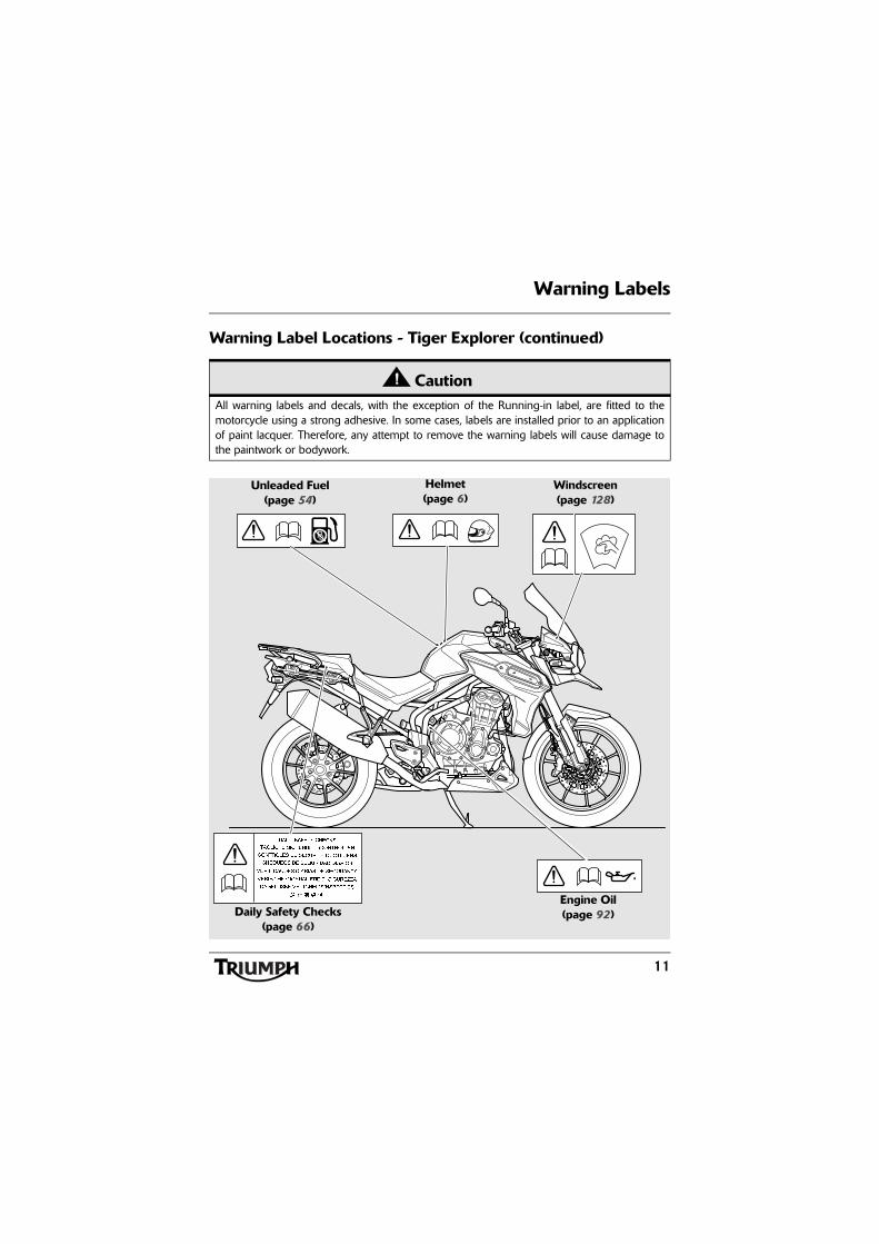
Warning Label Locations - Tiger Explorer (continued)
CautionAll warning labels and decals, with the exception of the Running-in label, are fitted to themotorcycle using a strong adhesive. In some cases, labels are installed prior to an applicationof paint lacquer. Therefore, any attempt to remove the warning labels will cause damage tothe paintwork or bodywork.
Pb
Daily Safety Checks(page 66)
Helmet(page 6)
Unleaded Fuel(page 54)
Engine Oil(page 92)
Windscreen(page 128)

12
Parts Identification
PARTS IDENTIFICATION
1. Headlight2. Front indicator3. Windscreen adjuster, left hand side4. Fuel tank and fuel filler cap5. Battery and fuse boxes6. Tool kit/Accessory U-lock storage
location7. Rear indicator8. Seat lock
9. Rear brake caliper10.Rear brake disc11. Centre stand12.Gear-change pedal13.Side stand14.Coolant expansion tank15.Radiator cowl16.Front brake caliper17. Front brake disc
1 2 4 5 6 7
8
111213151617 14
3
910

13
Parts Identification
PARTS IDENTIFICATION
18. Rear light19. Rear brake fluid reservoir20. Oil filler cap21. Mirror22. Front fork adjuster23. Windscreen adjuster, right hand side24. Headlight adjuster25. Screen
26. Front fork27. Engine oil level sight glass28. Clutch line29. Rear brake pedal30. Rear suspension spring pre-load
adjuster31. Silencer
18 19 20 21 24 25
2628 27293031
2322
14
Parts Identification
PARTS IDENTIFICATION
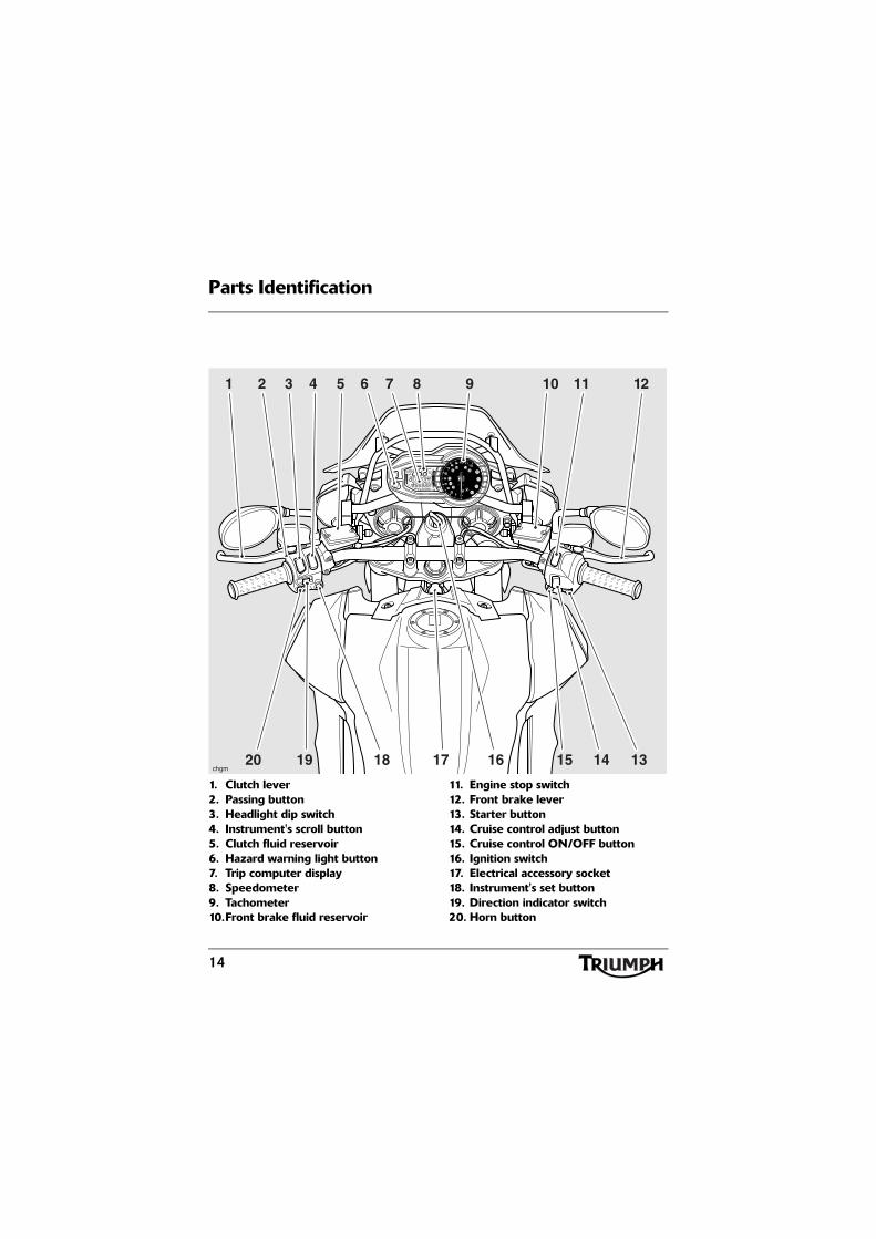
1. Clutch lever2. Passing button3. Headlight dip switch4. Instrument's scroll button5. Clutch fluid reservoir6. Hazard warning light button7. Trip computer display8. Speedometer9. Tachometer10.Front brake fluid reservoir
11. Engine stop switch12. Front brake lever13. Starter button14. Cruise control adjust button15. Cruise control ON/OFF button16. Ignition switch17. Electrical accessory socket18. Instrument's set button19. Direction indicator switch20. Horn button
FR
FR
MIN -1 x 1000
432 75 8 9 10 11 12
17 1314151620 19 18
1
chgm
6

15
Serial Numbers
SERIAL NUMBERS
Vehicle Identification Number (VIN)
1. VIN numberThe Vehicle Identification Number (VIN) isstamped into the steering head area of theframe. It is also displayed on a plate, rivetedto the left hand side of the frame, beneaththe seat.
Record the vehicle identification number inthe space provided below.
Engine Serial Number
1. Engine serial numberThe engine serial number is stamped on theengine crankcase, immediately below thegearbox.
Record the engine serial number in the spaceprovided below.
1
chgs
1
chev

16
Serial Numbers
This page intentionally left blank

General Information
17
GENERAL INFORMATION
Table of ContentsInstrument Panel Layout. . . . . . . . . . . . . . . . . . . . . . . . . . . . . . . . . . . . . . . . . . . . . . . . . . . . . . . 20
Speedometer and Odometer. . . . . . . . . . . . . . . . . . . . . . . . . . . . . . . . . . . . . . . . . . . . . . . . . . . 21
Tachometer . . . . . . . . . . . . . . . . . . . . . . . . . . . . . . . . . . . . . . . . . . . . . . . . . . . . . . . . . . . . . . . . . 21
Trip Computer . . . . . . . . . . . . . . . . . . . . . . . . . . . . . . . . . . . . . . . . . . . . . . . . . . . . . . . . . . . . . . 21
Odometer/Trip Meter . . . . . . . . . . . . . . . . . . . . . . . . . . . . . . . . . . . . . . . . . . . . . . . . . . . . . 22Trip Meter . . . . . . . . . . . . . . . . . . . . . . . . . . . . . . . . . . . . . . . . . . . . . . . . . . . . . . . . . . . . . . 22Trip Meter Reset . . . . . . . . . . . . . . . . . . . . . . . . . . . . . . . . . . . . . . . . . . . . . . . . . . . . . . . . . 23Air Temperature . . . . . . . . . . . . . . . . . . . . . . . . . . . . . . . . . . . . . . . . . . . . . . . . . . . . . . . . . 24Tyre Pressure Monitoring System (TPMS) - If Fitted . . . . . . . . . . . . . . . . . . . . . . . . . . . . . 24Function . . . . . . . . . . . . . . . . . . . . . . . . . . . . . . . . . . . . . . . . . . . . . . . . . . . . . . . . . . . . . . . . 24TPMS Sensor ID Number. . . . . . . . . . . . . . . . . . . . . . . . . . . . . . . . . . . . . . . . . . . . . . . . . . 25System Display . . . . . . . . . . . . . . . . . . . . . . . . . . . . . . . . . . . . . . . . . . . . . . . . . . . . . . . . . . 25Sensor Batteries . . . . . . . . . . . . . . . . . . . . . . . . . . . . . . . . . . . . . . . . . . . . . . . . . . . . . . . . . . 26TPMS symbol . . . . . . . . . . . . . . . . . . . . . . . . . . . . . . . . . . . . . . . . . . . . . . . . . . . . . . . . . . . 26Tyre Pressures . . . . . . . . . . . . . . . . . . . . . . . . . . . . . . . . . . . . . . . . . . . . . . . . . . . . . . . . . . . 26Replacement Tyres. . . . . . . . . . . . . . . . . . . . . . . . . . . . . . . . . . . . . . . . . . . . . . . . . . . . . . . . 26
Set Up Menu . . . . . . . . . . . . . . . . . . . . . . . . . . . . . . . . . . . . . . . . . . . . . . . . . . . . . . . . . . . . . . . 27
Service . . . . . . . . . . . . . . . . . . . . . . . . . . . . . . . . . . . . . . . . . . . . . . . . . . . . . . . . . . . . . . . . . 27Auto - Self Cancelling Indicators. . . . . . . . . . . . . . . . . . . . . . . . . . . . . . . . . . . . . . . . . . . . . 27Changing Units (Imperial, US or Metric) . . . . . . . . . . . . . . . . . . . . . . . . . . . . . . . . . . . . . . 28Clock Adjustment . . . . . . . . . . . . . . . . . . . . . . . . . . . . . . . . . . . . . . . . . . . . . . . . . . . . . . . . 29Triumph Traction Control - If Fitted . . . . . . . . . . . . . . . . . . . . . . . . . . . . . . . . . . . . . . . . . . 30Triumph Traction Control Settings . . . . . . . . . . . . . . . . . . . . . . . . . . . . . . . . . . . . . . . . . . . 31ABS Disable . . . . . . . . . . . . . . . . . . . . . . . . . . . . . . . . . . . . . . . . . . . . . . . . . . . . . . . . . . . . . 32Return . . . . . . . . . . . . . . . . . . . . . . . . . . . . . . . . . . . . . . . . . . . . . . . . . . . . . . . . . . . . . . . . . 32
Service Interval Indicator . . . . . . . . . . . . . . . . . . . . . . . . . . . . . . . . . . . . . . . . . . . . . . . . . . . . . . 33
Low Battery Warning . . . . . . . . . . . . . . . . . . . . . . . . . . . . . . . . . . . . . . . . . . . . . . . . . . . . . . . . . 33
Gear Position Display . . . . . . . . . . . . . . . . . . . . . . . . . . . . . . . . . . . . . . . . . . . . . . . . . . . . . . . . . 34
Coolant Temperature Gauge . . . . . . . . . . . . . . . . . . . . . . . . . . . . . . . . . . . . . . . . . . . . . . . . . . . 34
Fuel Gauge . . . . . . . . . . . . . . . . . . . . . . . . . . . . . . . . . . . . . . . . . . . . . . . . . . . . . . . . . . . . . . . . . 35
Heated Seats - If Fitted . . . . . . . . . . . . . . . . . . . . . . . . . . . . . . . . . . . . . . . . . . . . . . . . . . . . . . . . 35

General Information
18
Warning Lights . . . . . . . . . . . . . . . . . . . . . . . . . . . . . . . . . . . . . . . . . . . . . . . . . . . . . . . . . . . . . . 36
Direction Indicators . . . . . . . . . . . . . . . . . . . . . . . . . . . . . . . . . . . . . . . . . . . . . . . . . . . . . . . 36High Beam. . . . . . . . . . . . . . . . . . . . . . . . . . . . . . . . . . . . . . . . . . . . . . . . . . . . . . . . . . . . . . 36Low Fuel. . . . . . . . . . . . . . . . . . . . . . . . . . . . . . . . . . . . . . . . . . . . . . . . . . . . . . . . . . . . . . . . 36Neutral . . . . . . . . . . . . . . . . . . . . . . . . . . . . . . . . . . . . . . . . . . . . . . . . . . . . . . . . . . . . . . . . . 36Low Oil Pressure/Low Oil Level Warning Light. . . . . . . . . . . . . . . . . . . . . . . . . . . . . . . . . 36High Coolant Temperature Warning Light. . . . . . . . . . . . . . . . . . . . . . . . . . . . . . . . . . . . . 37Engine Management System Malfunction Indicator Light . . . . . . . . . . . . . . . . . . . . . . . . 38Alarm/Immobiliser Indicator Light . . . . . . . . . . . . . . . . . . . . . . . . . . . . . . . . . . . . . . . . . . . 38Tyre Pressure Warning Light . . . . . . . . . . . . . . . . . . . . . . . . . . . . . . . . . . . . . . . . . . . . . . . . 39Frost Symbol . . . . . . . . . . . . . . . . . . . . . . . . . . . . . . . . . . . . . . . . . . . . . . . . . . . . . . . . . . . . 40Traction Control Warning Light - If Traction Control is Fitted . . . . . . . . . . . . . . . . . . . . . . 41Cruise Control Light . . . . . . . . . . . . . . . . . . . . . . . . . . . . . . . . . . . . . . . . . . . . . . . . . . . . . . 41
Ignition Key . . . . . . . . . . . . . . . . . . . . . . . . . . . . . . . . . . . . . . . . . . . . . . . . . . . . . . . . . . . . . . . . . 42
Ignition Switch/Steering Lock. . . . . . . . . . . . . . . . . . . . . . . . . . . . . . . . . . . . . . . . . . . . . . . . . . . 43
Engine immobiliser . . . . . . . . . . . . . . . . . . . . . . . . . . . . . . . . . . . . . . . . . . . . . . . . . . . . . . . 43Ignition Switch Positions . . . . . . . . . . . . . . . . . . . . . . . . . . . . . . . . . . . . . . . . . . . . . . . . . . . 43
Brake and Clutch Lever Adjusters . . . . . . . . . . . . . . . . . . . . . . . . . . . . . . . . . . . . . . . . . . . . . . . 44
Right Handlebar Switches . . . . . . . . . . . . . . . . . . . . . . . . . . . . . . . . . . . . . . . . . . . . . . . . . . . . . 45
Engine Stop Switch . . . . . . . . . . . . . . . . . . . . . . . . . . . . . . . . . . . . . . . . . . . . . . . . . . . . . . . 45Starter Button . . . . . . . . . . . . . . . . . . . . . . . . . . . . . . . . . . . . . . . . . . . . . . . . . . . . . . . . . . . 46Cruise Control ON/OFF button . . . . . . . . . . . . . . . . . . . . . . . . . . . . . . . . . . . . . . . . . . . . . 46Cruise Control Adjust Button . . . . . . . . . . . . . . . . . . . . . . . . . . . . . . . . . . . . . . . . . . . . . . . 46
Left Handlebar Switches. . . . . . . . . . . . . . . . . . . . . . . . . . . . . . . . . . . . . . . . . . . . . . . . . . . . . . . 46
Headlight Dip Switch. . . . . . . . . . . . . . . . . . . . . . . . . . . . . . . . . . . . . . . . . . . . . . . . . . . . . . 47Direction Indicator Switch . . . . . . . . . . . . . . . . . . . . . . . . . . . . . . . . . . . . . . . . . . . . . . . . . . 47Hazard Warning Lights . . . . . . . . . . . . . . . . . . . . . . . . . . . . . . . . . . . . . . . . . . . . . . . . . . . . 48Horn Button. . . . . . . . . . . . . . . . . . . . . . . . . . . . . . . . . . . . . . . . . . . . . . . . . . . . . . . . . . . . . 48Pass Button . . . . . . . . . . . . . . . . . . . . . . . . . . . . . . . . . . . . . . . . . . . . . . . . . . . . . . . . . . . . . 48Instrument Scroll Button . . . . . . . . . . . . . . . . . . . . . . . . . . . . . . . . . . . . . . . . . . . . . . . . . . . 48Instrument Set Button . . . . . . . . . . . . . . . . . . . . . . . . . . . . . . . . . . . . . . . . . . . . . . . . . . . . . 48Front Fog Lights Switch, if fitted . . . . . . . . . . . . . . . . . . . . . . . . . . . . . . . . . . . . . . . . . . . . . 49
Throttle Control . . . . . . . . . . . . . . . . . . . . . . . . . . . . . . . . . . . . . . . . . . . . . . . . . . . . . . . . . . . . . 49
Brake Use . . . . . . . . . . . . . . . . . . . . . . . . . . . . . . . . . . . . . . . . . . . . . . . . . . . . . . . . . . . . . . 50

General Information
19
Cruise Control . . . . . . . . . . . . . . . . . . . . . . . . . . . . . . . . . . . . . . . . . . . . . . . . . . . . . . . . . . . . . . 50
Activating Cruise Control . . . . . . . . . . . . . . . . . . . . . . . . . . . . . . . . . . . . . . . . . . . . . . . . . . 51Resuming the Cruise Control Set Speed . . . . . . . . . . . . . . . . . . . . . . . . . . . . . . . . . . . . . . 52Increasing Speed while in Cruise Control . . . . . . . . . . . . . . . . . . . . . . . . . . . . . . . . . . . . . 53Decreasing Speed while in Cruise Control. . . . . . . . . . . . . . . . . . . . . . . . . . . . . . . . . . . . . 54Deactivating Cruise Control . . . . . . . . . . . . . . . . . . . . . . . . . . . . . . . . . . . . . . . . . . . . . . . . 54
Fuel Requirement/Refuelling . . . . . . . . . . . . . . . . . . . . . . . . . . . . . . . . . . . . . . . . . . . . . . . . . . . 54
Fuel Grade . . . . . . . . . . . . . . . . . . . . . . . . . . . . . . . . . . . . . . . . . . . . . . . . . . . . . . . . . . . . . . 54
Fuel Tank Cap . . . . . . . . . . . . . . . . . . . . . . . . . . . . . . . . . . . . . . . . . . . . . . . . . . . . . . . . . . . . . . . 55
Filling the Fuel Tank . . . . . . . . . . . . . . . . . . . . . . . . . . . . . . . . . . . . . . . . . . . . . . . . . . . . . . . . . . 56
Tool Kit, Handbook and the Triumph Accessory D-Lock . . . . . . . . . . . . . . . . . . . . . . . . . . . . . 56
Stands . . . . . . . . . . . . . . . . . . . . . . . . . . . . . . . . . . . . . . . . . . . . . . . . . . . . . . . . . . . . . . . . . . . . . 57
Side Stand . . . . . . . . . . . . . . . . . . . . . . . . . . . . . . . . . . . . . . . . . . . . . . . . . . . . . . . . . . . . . . 57Centre Stand . . . . . . . . . . . . . . . . . . . . . . . . . . . . . . . . . . . . . . . . . . . . . . . . . . . . . . . . . . . . 57
Seats . . . . . . . . . . . . . . . . . . . . . . . . . . . . . . . . . . . . . . . . . . . . . . . . . . . . . . . . . . . . . . . . . . . . . . 58
Seat Care . . . . . . . . . . . . . . . . . . . . . . . . . . . . . . . . . . . . . . . . . . . . . . . . . . . . . . . . . . . . . . . 58Rear Seat . . . . . . . . . . . . . . . . . . . . . . . . . . . . . . . . . . . . . . . . . . . . . . . . . . . . . . . . . . . . . . . 58Rider's Seat . . . . . . . . . . . . . . . . . . . . . . . . . . . . . . . . . . . . . . . . . . . . . . . . . . . . . . . . . . . . . 59Rider’s Seat Height Adjustment . . . . . . . . . . . . . . . . . . . . . . . . . . . . . . . . . . . . . . . . . . . . . 60
Helmet Hook . . . . . . . . . . . . . . . . . . . . . . . . . . . . . . . . . . . . . . . . . . . . . . . . . . . . . . . . . . . . . . . 61
Triumph Accessory D-lock Storage . . . . . . . . . . . . . . . . . . . . . . . . . . . . . . . . . . . . . . . . . . . . . . 61
Electrical Accessory Socket . . . . . . . . . . . . . . . . . . . . . . . . . . . . . . . . . . . . . . . . . . . . . . . . . . . . . 62
Handlebar Adjustment . . . . . . . . . . . . . . . . . . . . . . . . . . . . . . . . . . . . . . . . . . . . . . . . . . . . . . . . 62
Windscreen . . . . . . . . . . . . . . . . . . . . . . . . . . . . . . . . . . . . . . . . . . . . . . . . . . . . . . . . . . . . . . . . . 64
Running-In . . . . . . . . . . . . . . . . . . . . . . . . . . . . . . . . . . . . . . . . . . . . . . . . . . . . . . . . . . . . . . . . . 65
Safe Operation . . . . . . . . . . . . . . . . . . . . . . . . . . . . . . . . . . . . . . . . . . . . . . . . . . . . . . . . . . . . . . 66
Daily Safety Checks . . . . . . . . . . . . . . . . . . . . . . . . . . . . . . . . . . . . . . . . . . . . . . . . . . . . . . . 66

20
General Information
Instrument Panel Layout
1. Clock2. Service interval indicator3. Speedometer4. Fuel gauge5. Engine management malfunction
indicator light6. Left hand direction indicator light7. ABS warning light8. Tachometer 'red zone'9. Tyre pressure warning light (if Tyre
Pressure Monitoring System (TPMS) is fitted)
10.Right hand direction indicator light11. Neutral indicator light12.High beam indicator light13.Low fuel level indicator light14.Alarm/immobiliser status indicator
light (alarm is an accessory fit)
15. Traction control light (if traction control is fitted)
16. Cruise control light17. Tachometer18. High coolant temperature warning
light19. Low oil pressure/low oil level
warning light20. Tyre pressure display (if Tyre
Pressure Monitoring System (TPMS) is fitted)
21. Frost symbol22. Heated seat symbol (if heated seats
are fitted)23. Selected gear 24. Coolant temperature gauge25. Hazard warning lights button26. Home button
FR
FR
MIN -1 x 1000
2425 2023 22 21 1819 17 141516 13 12
21 3 4 5 6 7 8 9 10 11
chda
26
TC

21
General Information
Speedometer and OdometerThe digital speedometer indicates the roadspeed of the motorcycle. The read-outdisplays the motorcycle road speed inincrements of one mile (or kilometre) perhour.
The electronic odometer and two trip metersare in the display screen. For details of theoperation of the odometer and trip meters,please refer to the following pages.
TachometerThe tachometer shows the engine speed inrevolutions per minute - rpm (r/min). At theend of the tachometer range there is the'red zone'. Engine rpm (r/min) in the redzone is above maximum recommendedengine speed and is also above the range forbest performance.
Trip Computer
1. Scroll button, up2. Scroll button, down3. Set buttonTo access the trip computer information,press and release the set button on the lefthand switch cube until the desired display isvisible. The display will cycle through in thefollowing order:
• Trip Meter 1;
• Trip Meter 2;
• Air temperature;
• Tyre Pressure Monitoring system -if fitted;
• Set up.
Note:
• The tyre pressure monitoringsystem (TPMS) is an accessorywhich must be fitted by yourauthorised Triumph dealer. TheTPMS display will then beactivated by your authorisedTriumph dealer.
CautionNever allow engine rpm to enter the'red zone' as severe engine damage mayresult.
1
2
3chdb_2

22
General Information
Odometer/Trip Meter
1. Odometer/Trip meter display2. Trip meter 1 display3. Trip meter 2 display
Trip MeterEither trip meter shows the distance that themotorcycle has travelled, journey time,average fuel consumption, instantaneous fuelconsumption and average speed, all since thetrip meter on display was last reset to zero.
To access the trip meter information, turn theignition to the ON position. Press and releasethe set button on the left hand switch cubeuntil the desired trip meter is visible in thedisplay screen.
Press and release scroll button on the lefthand switch cube until the desired display isvisible. The display will scroll through in thefollowing order when pressing up on thescroll button (it will scroll through in thereverse order if down on the button ispressed):
• Odometer;
• Cruise control;
• Average speed;
• Instantaneous fuel consumption;
• Average fuel consumption;
• Journey time;
• Range to empty;
• Journey distance.
Each display provides the followinginformation:
OdometerShows the total distance that the motorcyclehas travelled.
3
cgjp_9
1
2

23
General Information
Cruise ControlIf the cruise control is activated, this displaywill show the road speed set for cruisecontrol. If the cruise control is not activated,two dashes will be visible in the display area.
Average SpeedThe average speed is calculated from whenthe trip computer was last reset. After beingreset the display will show dashes until1 mile/km has been covered.
Instantaneous Fuel ConsumptionAn indication of the fuel consumption at aninstant in time.
Average Fuel ConsumptionAn indication of the average fuelconsumption. After being reset the displaywill show dashes until 0.1 miles/km has beencovered.
Journey TimeThe total time elapsed since the trip meterwas last set to zero.
Range to EmptyThis is an indication of the probable distancethat can be travelled on the remaining fuel inthe tank.
Journey DistanceThe total journey distance travelled since thetrip meter was last set to zero.
Trip Meter ResetTo reset either of the trip meters, select anddisplay the trip meter to be zeroed then pressthe set button for 2 seconds. After 2 seconds,the trip meter on display will reset to zero.
Note:
• When a trip meter is reset to zero,the journey time, average fuelconsumption and average speedwill also be set to zero for that tripmeter.
To exit the trip meter, press and release homebutton and the odometer in the trip 1 menuwill be visible in the display screen.
1. Home button
1

24
General Information
Air TemperatureThe air temperature, when selected, willdisplay the ambient air temperature in ºC orºF.
To access the air temperature display, turnthe ignition to the ON position.
Press and release the set button on the lefthand switch cube until AIR is visible in thedisplay screen.
To exit the air temperature display, press andrelease the home button and the odometer inthe trip 1 menu will be visible in the displayscreen.
1. Air temperature shown in ºCTo change the temperature from ºC or ºF,refer to Changing Units on page 28.
Tyre Pressure Monitoring System (TPMS) - If Fitted
FunctionTyre pressure sensors are fitted to the frontand rear wheels. These sensors measure theair pressure inside the tyre and transmitpressure data to the instruments. Thesesensors will not transmit the data until themotorcycle is travelling at a speed greaterthan 12 mph (20 km). Two dashes will bevisible in the display area until the tyrepressure signal is received.
An adhesive label will be fitted to the wheelrim to indicate the position of the tyrepressure sensor, which is near the valve.
For motorcycles without the tyrepressure monitoring system fitted: Thetyre pressure monitoring system (TPMS) is anaccessory fitted item and must be fitted byyour authorised Triumph dealer. The TPMSdisplay on the instruments will only beactivated when the system has been fitted.
1
WarningThe daily check of tyre pressures must notbe excluded because of the fitment of theTPMS. Check the tyre pressure when thetyres are cold and using an accurate tyrepressure gauge (see page 111).
Use of the TPMS system to set inflationpressures may lead to incorrect tyrepressures leading to loss of motorcyclecontrol and an accident.

25
General Information
TPMS Sensor ID NumberAn ID number for each tyre pressure sensoris printed on a label which is on the sensor.This number may be required by the dealerfor service or diagnostics.
If the TPMS has been fitted at the factory,labels identifying the front and rear TPMSsensor ID numbers will be affixed to thespaces below.
If the TPMS is being fitted to the motorcycleas an accessory, ensure that the dealerrecords the front and rear TPMS sensor IDnumbers in the spaces provided below.
System Display
1. TPMS symbol2. Tyre pressure display3. Front tyre, identified4. Rear tyre, identified
To access the tyre pressure display, turn theignition to the ON position.
Press and release the set button on the lefthand switch cube until 'PSI' or 'bAr' is visiblein the display screen.
Press and release the scroll button to selectthe front or rear tyre pressure.
When the tyre pressure monitoring systemhas been selected, — — 'PSI' or 'bAr' will bevisible in the display screen until themotorcycle is travelling at a speed greaterthan 12 mph (20 km) and the tyre pressuresignal is received.
To exit the tyre pressure display, press andrelease the home button and the odometer intrip 1 menu will be displayed.
Front Sensor
Rear Sensor
cgjp_6_1
4
3
2
1

26
General Information
Sensor BatteriesWhen the battery voltage in a pressuresensor is low, 'lo bAtt' will be displayed foreight seconds and the TPMS symbol willindicate which wheel sensor has the lowbattery voltage. If the batteries are completelyflat, only dashes will be visible in the displayscreen, the red TPMS warning light will beon and the TPMS symbol will flashcontinuously. Contact your authorisedTriumph dealer to have the sensor replacedand the new serial number recorded in thespaces provided on page 25.
1. TPMS symbol2. Display screen3. Front tyre, identified4. Rear tyre, identified5. TPMS warning light
TPMS symbolWith the ignition switch turned to the ONposition, if the TPMS symbol flashes for10 seconds and then remains on there is afault with the TPMS system. Contact yourauthorised Triumph dealer to have the faultrectified.
Tyre PressuresThe tyre pressures shown on your instrumentpanel indicate the actual tyre pressure at thetime of selecting the display. This may differfrom the inflation pressure set when the tyresare cold because tyres become warmerduring riding, causing the air in the tyre toexpand and the inflation pressure to increase.The cold inflation pressures specified byTriumph take account of this.
Owners must only adjust tyre pressures whenthe tyres are cold using an accurate tyrepressure gauge (see page 111), and must notuse the tyre pressure display on theinstruments.
Replacement TyresWhen replacing tyres, always have anauthorised Triumph dealer fit your tyres andensure they are aware that tyre pressuresensors are fitted to the wheels (seepage 113).
FR
MIN-1 x 1000
TC4
2
1 3 5
WarningThe tyre pressure monitoring system is notto be used as a tyre pressure gauge whenadjusting the tyre pressures. For correcttyre pressures, always check the tyrepressures when the tyres are cold andusing an accurate tyre pressure gauge (seepage 111).
Use of the TPMS system to set inflationpressures may lead to incorrect tyrepressures leading to loss of motorcyclecontrol and an accident.

27
General Information
Set Up MenuTo access the set up menu; with themotorcycle stationary and in neutral, pressand release the set button on the left handswitch cube until 'SEtUP' is visible in thedisplay screen.
Press and release the scroll button until thedesired display is visible. The display will scrollthrough in the following order when pressingup on the scroll button (it will scroll throughin the reverse order if down on the button ispressed):
• Service;
• Auto - self cancelling indicators;
• Units - change units (Imperial, US orMetric;
• t-set - clock adjustment;
• ttc - Triumph traction control (iffitted);
• ABS.
Each display provides the followinginformation:
ServiceShows the total distance that the motorcyclehas remaining before a service is required(see page 33).
Auto - Self Cancelling IndicatorsThis Triumph model has a self cancellingindicator function that can be disabled orenabled.
To disable or enable the self cancellingindicators; with the motorcycle stationary andin neutral, press and release the set button onthe left hand switch cube until 'SEtUP' isvisible in the display screen.
Press and release the scroll button until 'Auto'or 'MAnUAL' is visible in the display screen.
Press and release the set button and Auto orMAnUAL will flash on and off.
Press and release the scroll button to selectAuto or MAnUAL then press the set button.
• Auto - Indicator self cancelling is on(see page 47).
• MAnUAL - auto self cancelling is off.The indicators will need to bemanually turned off (see page 47).
1. Auto selected To exit the auto menu, press and release thehome button and the odometer in the trip 1menu will be visible in the display screen.
cgjp_6_2
1
28
General Information
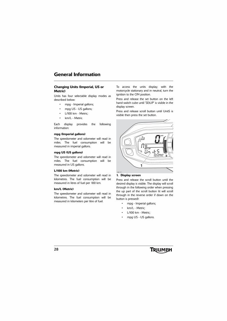
Changing Units (Imperial, US or Metric)Units has four selectable display modes asdescribed below:
• mpg - Imperial gallons;
• mpg US - US gallons;
• L/100 km - Metric;
• km/L - Metric.
Each display provides the followinginformation:
mpg (Imperial gallons)The speedometer and odometer will read inmiles. The fuel consumption will bemeasured in imperial gallons.
mpg US (US gallons) The speedometer and odometer will read inmiles. The fuel consumption will bemeasured in US gallons.
L/100 km (Metric)The speedometer and odometer will read inkilometres. The fuel consumption will bemeasured in litres of fuel per 100 km.
km/L (Metric)The speedometer and odometer will read inkilometres. The fuel consumption will bemeasured in kilometers per litre of fuel.
To access the units display; with themotorcycle stationary and in neutral, turn theignition to the ON position.
Press and release the set button on the lefthand switch cube until 'SEtUP' is visible in thedisplay screen.
Press and release scroll button until UnitS isvisible then press the set button.
1. Display screenPress and release the scroll button until thedesired display is visible. The display will scrollthrough in the following order when pressingthe up part of the scroll button (it will scrollthrough in the reverse order if down on thebutton is pressed):
• mpg - Imperial gallons;
• km/L - Metric;
• L/100 km - Metric;
• mpg US - US gallons.
cgjp_3_1
1
29
General Information
Models without TPMS: Press the setbutton and do not touch the scroll or setbuttons again until ºC or ºF is visible. Pressand release the scroll button until the desiredtemperature unit is displayed. Then press theset button and wait until UnitS is visible in thedisplay screen. When UnitS is visible in thedisplay screen, press and release the homebutton and the odometer in the trip 1 menuwill be visible in the display screen.
Models with TPMS: Press the set buttonand do not touch the scroll or set buttonsagain until PSI or bAr is displayed. Press andrelease the scroll button until the desired tyrepressure units are visible. Press the set buttonand wait until ºC or ºF is visible. Press andrelease the scroll button until the desiredtemperature unit is displayed. Then press theset button and wait until UnitS is displayed,then press the home button and theodometer in the trip 1 menu will be visible inthe display screen.
Clock AdjustmentTo reset the clock; with the motorcyclestationary and in neutral turn the ignition tothe ON position. Press and release the setbutton on the left hand switch cube until'SEtUP' is visible in the display screen. Pressand release the scroll button until t-SEt isvisible.
Press the set button again and either 24 Hror 12 Hr clock will be shown. Press the scrollbutton to select the desired clock display andthen press the set button. The hour displaywill start to flash and the word Hour is visiblein the display screen.
Note:
• The hour/minute display willincrease when pressing the up partof the scroll button or decreasewhen pressing the down part ofthe button.
To reset the hour display, ensure that thehour display is still flashing and the wordHour is visible. Press the scroll button tochange the setting. Each individual buttonpress will change the setting by one digit. Ifthe button is held, the display willcontinuously scroll through in single digitincrements.

30
General Information
When the correct hour display is shown,press the set button. The minutes display willbegin to flash and the word Min is visible inthe display screen. The minutes display isadjusted in the same way as for the hours.
Once both hours and minutes are correctlyset, press the set button to confirm and t-SEtwill be visible in the display screen. Press thehome button and the odometer in the trip 1menu will be visible in the display screen.
1. Clock display2. Hours read-out3. Minutes read-out4. Display screen (Hour selected for
adjustment)5. Home button
Triumph Traction Control - If Fitted
If fitted, this Triumph model has tractioncontrol to help maintain traction whenaccelerating on wet/slippery road surfaces. Ifsensors detect that the rear wheel is losingtraction (slipping), the traction control systemwill engage and alter the engine power untiltraction to the rear wheel has been restored.The traction control warning light will flashwhile it is engaged and the rider may notice achange to the sound of the engine.
Note:
• Traction control will not function ifthere is a malfunction with theABS system. The warning lights forthe ABS, traction control and theMIL will be illuminated.
cgjp_2_1
52
3
41
WarningTriumph traction control is not a substitutefor riding appropriately for the prevailingroad and weather conditions. The tractioncontrol cannot prevent loss of traction dueto:
• excessive speed when enteringturns;
• accelerating at a sharp lean angle;
• braking.
Traction control can not prevent the frontwheel from slipping.
Failure to observe any of the above mayresult in loss of motorcycle control and anaccident.

31
General Information
Triumph Traction Control Settings
The Triumph traction control can be set toone of the following conditions:
• '01' - the traction control will engageat a low level of rear wheel slip.The warning light will be off but willflash on and off when the tractioncontrol is working to limit the rearwheel slipping;
• '02' - suitable for advanced riders.The traction control will engage at ahigher level of rear wheel slip.The warning lamp will constantlyflash on and off slowly but will flashat a faster rate when the tractioncontrol is working to limit rear wheelslip;
• 'oFF' - traction control is disabledand the warning light is constantlyon.
To access the traction control settings; withthe motorcycle stationary and in neutral, turnthe ignition to the ON position.
Press and release the set button on the lefthand switch cube until 'SEtUP' is visible in thedisplay screen.
Press and release the scroll button until 'ttc' isvisible.
Press the set button and '01', '02' or 'oFF' willbe displayed.
Press and release the scroll button until thedesired setting is visible in the display screen.Press the set button and do not touch thescroll or set buttons again until the desiredsetting has stopped flashing.
Press the home button and the odometer inthe trip 1 menu will be visible in the displayscreen.
The Triumph traction control setting will resetto '01' when the ignition is turned off thenon.
WarningDo not attempt to adjust the tractioncontrol settings while the motorcycle is inmotion as this may lead to loss ofmotorcycle control and an accident.
WarningIf the traction control is disabled, themotorcycle will handle as normal butwithout traction control. In this situationaccelerating too hard on wet/slippery roadsurfaces may cause the rear wheel to slip,and may result in loss of motorcyclecontrol and an accident.

32
General Information
ABS DisableIt is possible to temporarily disable the ABSsystem. The ABS system cannot bepermanently disabled, it will be automaticallyenabled when the ignition is turned off andthen on again.
To Disable the ABSTo access the ABS Disable function; with themotorcycle stationary and in neutral, turn theignition to the ON position.
Press and release the set button on the lefthand switch cube until 'SEtUP' is visible in thedisplay screen.
Press and release the scroll button until AbSis visible.
Press the set button and 'on' or 'oFF' will bedisplayed.
Press and release the scroll button until 'oFF'is visible in the display screen.
Pressing the set button will disable the ABSsystem; the message ABS OFF will bedisplayed for 2 seconds, and the ABSwarning light will be illuminated.
Note:
• With the ABS disabled, thetraction control will still function.
To Enable the ABSTo enable the ABS system again, repeat theABS disable procedure and select 'on'.
Press the home button and the odometer inthe trip 1 menu will be visible in the displayscreen.
An alternative way to enable the ABS is toturn the ignition off and on.
ReturnWhen return is displayed and the set buttonis pressed, trip 1 menu will be visible in thedisplay screen.
WarningIf the ABS is disabled, the brake system willfunction as a non-ABS braking system. Inthis situation braking too hard will causethe wheels to lock, and may result in loss ofmotorcycle control and an accident.

33
General Information
Service Interval Indicator
1. Service indicator2. Remaining distance
When the ignition is switched on and thedistance to the next service is 500 miles(800 km) or less, the service symbol will bedisplayed for 3 seconds and the clock willshow the distance remaining before the nextservice.
When the remaining distance is 0 miles(0 km) the service symbol will remain on untilthe service has been carried out and thesystem has been reset by your authorisedTriumph dealer. If the service is overdue, thedistance will be displayed as a negativenumber.
Low Battery WarningIf accessory items such as heated seats,heated grips and fog lights are fitted and areon with the engine at idle, over a period oftime, the battery voltage may drop below apredetermined voltage and cause the'bAt Lo' to be visible in the display screen.
If 'bAt Lo' is visible and the heated grips andheated seats are on, they will be automaticallyswitched off to allow the charging system tocharge the battery. The engine idle speedmay also be increased.
If necessary have the battery and chargingsystem checked by your authorised Triumphdealer.
The display will remain on until one of thefollowing conditions is met:
• The charging system has chargedthe battery;
• Either the scroll or set buttons on theleft hand switch cube has beenpressed;
• The ignition switch has been turnedto the OFF position.
1. Display screen
cgjp_4
2
1
cgjp_3_2
1

34
General Information
Gear Position Display
1. Gear position display (neutral position displayed)
2. Gear position symbol
The gear position display indicates whichgear (1 to 6) has been engaged. When thetransmission is in neutral (no gear selected),the display will show 'n'.
1. Gear position display (first gear shown)
Coolant Temperature Gauge
1. Coolant temperature gaugeThe coolant temperature gauge indicates thetemperature of the engine coolant.
When the ignition is switched on, all 8 bars ofthe display will be shown. When the engine isstarted from cold the display will show 1 bar.As the temperature increases more bars inthe display will be shown. When the engine isstarted from hot the display will show therelevant number of bars, dependant onengine temperature.
The normal temperature range is between4 and 6 bars.
If the coolant temperature becomes too highthe display will show 8 bars and will start toflash. The high coolant temperature light inthe tachometer will also be illuminated.
1
2
1
CautionDo not continue to run the engine if eitherof the high temperature warnings aredisplayed as severe engine damage mayresult.
1

35
General Information
Fuel Gauge
1. Fuel gaugeThe fuel gauge indicates the amount of fuelin the tank.
With the ignition switched on, the number ofbars shown in the display indicates the levelof fuel.
When the fuel tank is full all 12 bars aredisplayed and when empty, no bars aredisplayed. Other gauge markings indicateintermediate fuel levels between full andempty.
When 2 bars are displayed the low fuelwarning light will illuminate, 5 seconds laterthe display screen will switch to 'Range'display (see page 23). This indicates there areapproximately 4.5 litres of fuel remaining inthe tank and you should refuel at the earliestopportunity.
After refuelling, the fuel gauge and range toempty information will be updated only whileriding the motorcycle. Depending on theriding style, updating could take up to fiveminutes.
Heated Seats - If Fitted
1. Heated seats symbolHeated seats are an accessory fitted item.Both the rider's and pillion's heated seat hasOFF, LOW and HIGH settings. The heatedseats symbol in the instruments will showwhich seats are on but will only display theheat setting selected for the rider's seat.
When the heated seats are on, the symbol inthe instrument's will illuminate as shownbelow.
Front seat only, low heat.
Front seat only, high heat.
Rear seat only, low or high heat.
Front and rear seat with thefront seat on high. If the frontseat is on low, only the left handdot will be illuminated.
1
cgjp_5
1
cgjp_5_1

36
General Information
Warning Lights
Note:
• When the ignition is switched on,the instrument warning lights willilluminate for 2 seconds and willthen go off (except those whichremain on until the engine starts,as described in the followingpages).
Direction IndicatorsWhen the indicator switch ispushed to the left or right, the
turn indicator light will flash on and off at thesame speed as the turn indicators.
High BeamWhen the ignition is switched onand the headlight dip switch is setto 'high beam', the high beam
warning light will illuminate.
Low FuelThe low fuel indicator willilluminate when there areapproximately 4.5 litres of fuelremaining in the tank.
NeutralThe neutral warning lightindicates when the transmission isin neutral (no gear selected). The
warning light will illuminate when thetransmission is in neutral with the ignitionswitch in the ON position.
Low Oil Pressure/Low Oil Level Warning Light
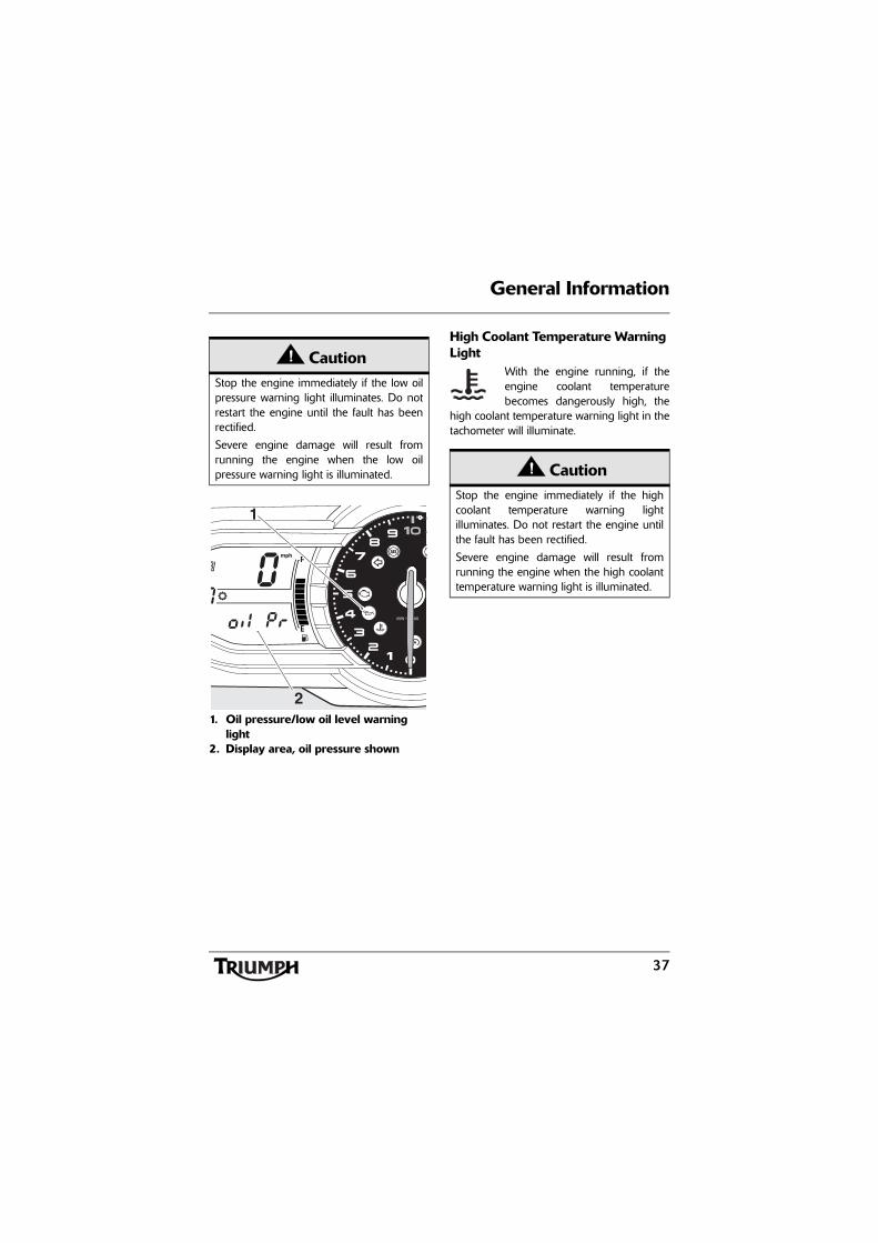
With the engine running, if the engine oilpressure becomes dangerously low, the lowoil pressure/low oil level warning light in thetachometer will illuminate and 'oil Pr' will alsobe visible in the display screen.
CautionRunning the engine with insufficient oil willcause engine damage. If 'oil Lo' is visible inthe display screen do not start the engine.Investigate the cause before attempting tostart the engine.
37
General Information
1. Oil pressure/low oil level warning light
2. Display area, oil pressure shown
High Coolant Temperature Warning Light
With the engine running, if theengine coolant temperaturebecomes dangerously high, the
high coolant temperature warning light in thetachometer will illuminate.
CautionStop the engine immediately if the low oilpressure warning light illuminates. Do notrestart the engine until the fault has beenrectified.
Severe engine damage will result fromrunning the engine when the low oilpressure warning light is illuminated.
MIN-1 x 1000
2
1
CautionStop the engine immediately if the highcoolant temperature warning lightilluminates. Do not restart the engine untilthe fault has been rectified.
Severe engine damage will result fromrunning the engine when the high coolanttemperature warning light is illuminated.

38
General Information
Engine Management System Malfunction Indicator Light
The malfunction indicator light forthe engine management systemilluminates briefly when the
ignition is switched on (to indicate that it isworking), but should not become illuminatedwhen the engine is running.
If the malfunction indicator light becomesilluminated when the engine is running, thisindicates that a fault has occurred in one ormore of the systems controlled by the enginemanagement system. In such circumstances,the engine management system will switch to'limp-home' mode so that the journey maybe completed, if the fault is not so severe thatthe engine will not run.
Note:
• If the malfunction indicator lightflashes when the ignition isswitched on, contact an authorisedTriumph dealer as soon as possibleto have the situation rectified. Inthese circumstances the enginewill not start.
Alarm/Immobiliser Indicator LightThis Triumph model is fitted withan engine immobiliser which isactivated when the ignition switch
is turned to the OFF position. If themotorcycle is fitted with a genuine Triumphaccessory alarm, the immobiliser will operateas normal but the alarm/immobiliser light willoperate as described below.
With Alarm FittedThe alarm/immobiliser light will onlyilluminate when the conditions described inthe genuine triumph accessory alarminstructions are met.
Without Alarm FittedWhen the ignition switch turned to theOFF position, the alarm/immobiliser light willflash on and off for 24 hours to show that theengine immobiliser is on. When the ignitionswitch is turned to the ON position theimmobiliser and the indicator light will be off.
If the indicator light remains on it indicatesthat the immobiliser has a malfunction thatrequires investigation. Contact an authorisedTriumph dealer as soon as possible to havethe fault checked and rectified.
WarningReduce speed and do not continue to ridefor longer than is necessary with themalfunction indicator light illuminated. Thefault may adversely affect engineperformance, exhaust emissions and fuelconsumption. Reduced engineperformance could cause a dangerousriding condition, leading to loss of controland an accident. Contact an authorisedTriumph dealer as soon as possible to havethe fault checked and rectified.

39
General Information
ABS (Anti-Lock Brake System) Indicator light
Note:
• Cruise control and tractioncontrol will not function ifthere is a malfunction withthe ABS system and the ABSwarning light is illuminated.
When the ignition switch is turned to the ONposition, it is normal that the ABS warninglight will flash on and off. The light willcontinue to flash after engine start-up untilthe motorcycle first reaches a speedexceeding 6 mph (10 km/h) when it will gooff.
Unless the ABS system is disabled (seepage 32), or there is a fault, it should notilluminate again until the engine is restarted.
If the indicator light becomes illuminated atany other time while riding it indicates thatthe ABS has a malfunction that requiresinvestigation.
See also Braking on page 73.
Tyre Pressure Warning LightThe tyre pressure warning lightworks in conjunction with the tyrepressure monitoring system (seepage 24).
The warning light will only illuminate whenthe front or rear tyre pressure is below therecommended pressure. It will not illuminateif the tyre is over inflated.
When the warning light is illuminated, theTPMS symbol indicating which is the deflatedtyre and its pressure will automatically bevisible in the display area.
1. TPMS symbol2. Rear tyre, identified3. Tyre pressure4. Tyre pressure warning light
WarningIf the ABS is not functioning, the brakesystem will continue to function as a nonABS braking system. Do not continue toride for longer than is necessary with theindicator light illuminated. Contact anauthorised Triumph dealer as soon aspossible to have the fault checked andrectified. In this situation braking too hardwill cause the wheels to lock resulting inloss of control and an accident.
cgjp_8
2
3
14
40
General Information
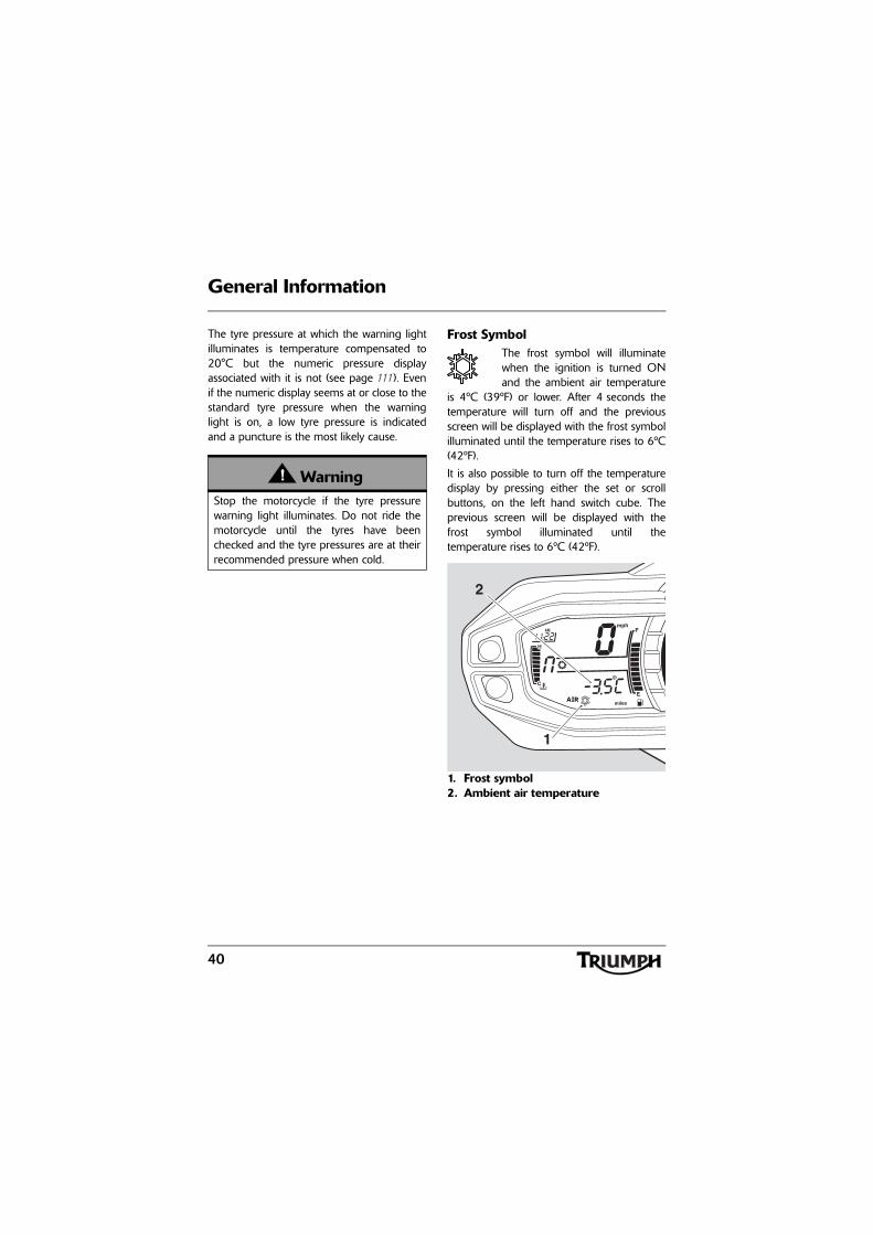
The tyre pressure at which the warning lightilluminates is temperature compensated to20°C but the numeric pressure displayassociated with it is not (see page 111). Evenif the numeric display seems at or close to thestandard tyre pressure when the warninglight is on, a low tyre pressure is indicatedand a puncture is the most likely cause.
Frost SymbolThe frost symbol will illuminatewhen the ignition is turned ONand the ambient air temperature
is 4ºC (39ºF) or lower. After 4 seconds thetemperature will turn off and the previousscreen will be displayed with the frost symbolilluminated until the temperature rises to 6ºC(42ºF).
It is also possible to turn off the temperaturedisplay by pressing either the set or scrollbuttons, on the left hand switch cube. Theprevious screen will be displayed with thefrost symbol illuminated until thetemperature rises to 6ºC (42ºF).
1. Frost symbol2. Ambient air temperature
WarningStop the motorcycle if the tyre pressurewarning light illuminates. Do not ride themotorcycle until the tyres have beenchecked and the tyre pressures are at theirrecommended pressure when cold.
1
2

41
General Information
Traction Control Warning Light - If Traction Control is Fitted
Depending on what setting hasbeen selected for the tractioncontrol system (see page 30), thewarning light will illuminate asfollows:
• '01' - the light is OFF but it will flashon and off when the traction controlis working to limit rear wheel spin;
• '02' - the light will flash on and offslowly but will flash on and off at afaster rate when the traction controlis working to limit rear wheel spin;
• 'oFF' - the light is constantly on.
If the traction control light and themalfunction indicator light (MIL) becomeilluminated at the same time, there is amalfunction with the traction control whichrequires investigation by your local Triumphdealer.
Cruise Control LightThe cruise control can only beactivated when the motorcycle istravelling at a speed between
30 to 100 mph (48 to 160 kmh) and is in4th gear or higher. When activated, the cruisecontrol light in the instrument's will beilluminated (see page 50).
1. Cruise control light
WarningIf the traction control is not functioning,care must be taken when accelerating andcornering on wet/slippery road surfaces toavoid rear wheel spin. Do not continue toride for longer than is necessary with theMIL and traction control lights illuminated.Contact an authorised Triumph dealer assoon as possible to have the fault checked.
Hard acceleration and cornering in thissituation may cause the rear wheel to spinresulting in loss of motorcycle control andan accident.
TC
WarningCruise control must only be used whereyou can ride safely at a steady speed.
Cruise control should not be used whenriding in heavy traffic, on roads with sharp/blind bends or when they are slippery.
Using cruise control in heavy traffic, onroads with sharp/blind bends or when theyare slippery, may result in loss ofmotorcycle control and an accident.
MIN-1 x 1000
TC
1
42
General Information
Ignition Key
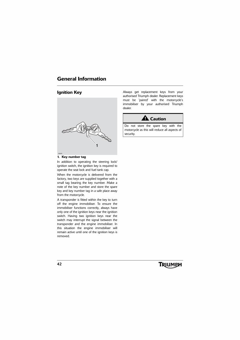
1. Key number tagIn addition to operating the steering lock/ignition switch, the ignition key is required tooperate the seat lock and fuel tank cap.
When the motorcycle is delivered from thefactory, two keys are supplied together with asmall tag bearing the key number. Make anote of the key number and store the sparekey and key number tag in a safe place awayfrom the motorcycle.
A transponder is fitted within the key to turnoff the engine immobiliser. To ensure theimmobiliser functions correctly, always haveonly one of the ignition keys near the ignitionswitch. Having two ignition keys near theswitch may interrupt the signal between thetransponder and the engine immobiliser. Inthis situation the engine immobiliser willremain active until one of the ignition keys isremoved.
Always get replacement keys from yourauthorised Triumph dealer. Replacement keysmust be 'paired' with the motorcycle’simmobiliser by your authorised Triumphdealer.
ceom
1
CautionDo not store the spare key with themotorcycle as this will reduce all aspects ofsecurity.

43
General Information
Ignition Switch/Steering Lock
1. Ignition switch/steering lock2. LOCK position3. OFF position4. ON position5. PARK position
Engine immobiliserThe ignition barrel housing acts as theantenna for the engine immobiliser.
When the ignition switch is turned to the OFFposition and the ignition key is removed, theengine immobiliser is on (see page 38). Theengine immobiliser is turned off when theignition key is in the ignition switch and it isturned to the ON position.
Ignition Switch PositionsThis is a four position, key operated switch.The key can be removed from the switchonly when it is in the OFF, LOCK or P (PARK)position.
TO LOCK: Turn the handlebar fully to theleft, turn the key to the OFF position, pushand fully release the key, then rotate it to theLOCK position.
PARKING: Turn the key from the LOCKposition to the P position. The steering willremain locked, and the position lights will beswitched on.
Note:
• Do not leave the steering lock inthe P position for long periods oftime as this will cause the batteryto discharge.
PU
SH
P
OFF
ON
3
2
5
1
4
WarningFor reasons of security and safety, alwaysmove the ignition switch to theOFF position and remove the key whenleaving the motorcycle unattended.
Any unauthorised use of the motorcyclemay cause injury to the rider, other roadusers and pedestrians and may also causedamage to the motorcycle.
44
General Information
Brake and Clutch Lever Adjusters
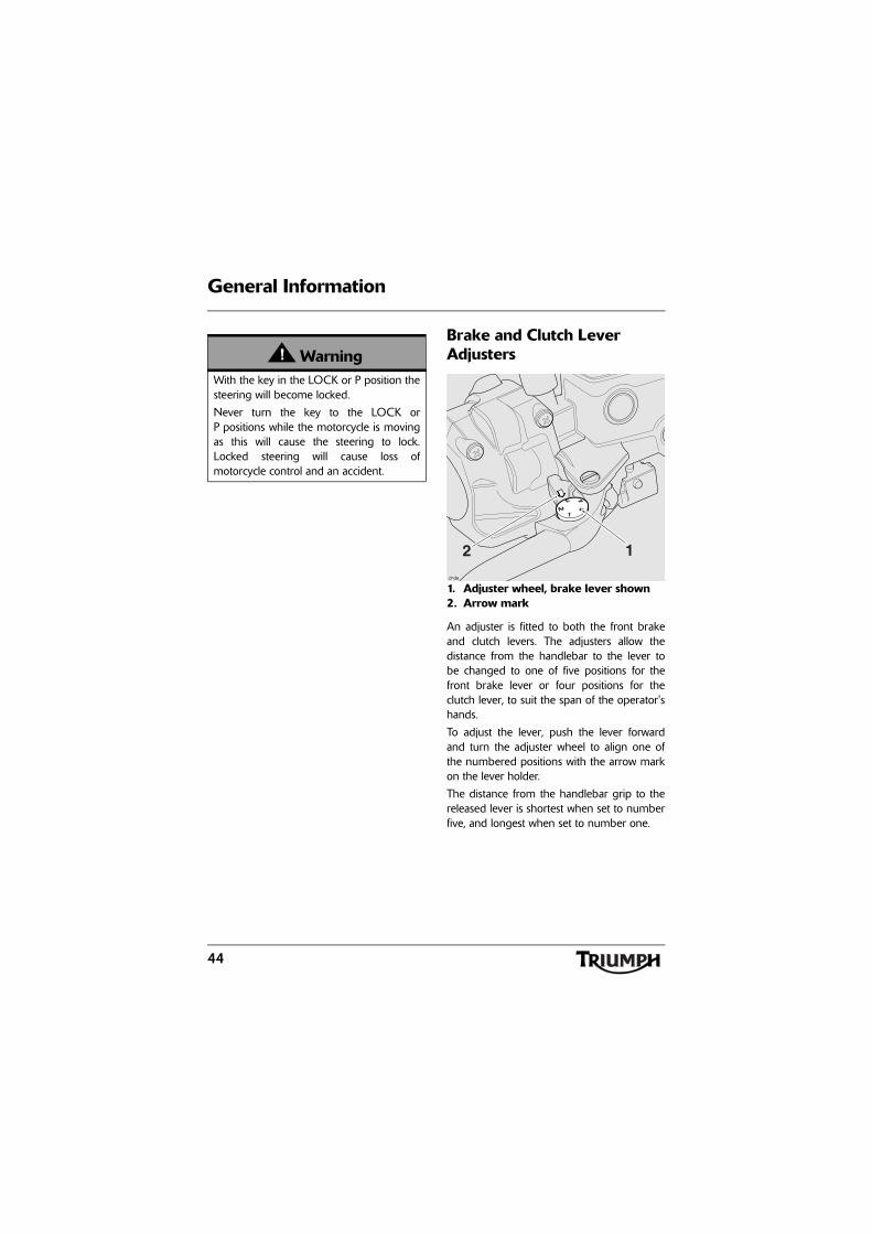
1. Adjuster wheel, brake lever shown2. Arrow mark
An adjuster is fitted to both the front brakeand clutch levers. The adjusters allow thedistance from the handlebar to the lever tobe changed to one of five positions for thefront brake lever or four positions for theclutch lever, to suit the span of the operator'shands.
To adjust the lever, push the lever forwardand turn the adjuster wheel to align one ofthe numbered positions with the arrow markon the lever holder.
The distance from the handlebar grip to thereleased lever is shortest when set to numberfive, and longest when set to number one.
WarningWith the key in the LOCK or P position thesteering will become locked.
Never turn the key to the LOCK orP positions while the motorcycle is movingas this will cause the steering to lock.Locked steering will cause loss ofmotorcycle control and an accident.
2 1
chde

45
General Information
Right Handlebar Switches
1. Engine stop switch2. Starter button3. Cruise control adjust button4. Cruise control ON/OFF button
Engine Stop SwitchIn addition to the ignition switch being turnedto the ON position, the engine stop switchmust be in the RUN position for themotorcycle to operate.
The engine stop switch is for emergency use.If an emergency arises which requires theengine to be stopped, move the engine stopswitch to the STOP position.
Note:
• Although the engine stop switchstops the engine, it does not turnoff all the electrical circuits andmay cause difficulty in restartingthe engine due to a dischargedbattery. Ordinarily, only theignition switch should be used tostop the engine.
WarningDo not attempt to adjust the lever with themotorcycle in motion as this may lead toloss of motorcycle control and an accident.
After adjusting the lever, operate themotorcycle in an area free from traffic togain familiarity with the new lever setting.Do not loan your motorcycle to anyone asthey may change the lever setting from theone you are familiar with causing loss ofcontrol or an accident.
4 2
3
1
chdc

46
General Information
Starter ButtonThe starter button operates the electricstarter. For the starter to operate, the clutchlever must be pulled to the handlebar.
Note:
• Even if the clutch lever is pulled tothe handlebar, the starter will notoperate if the side stand is downand a gear is engaged.
Cruise Control ON/OFF buttonWhen the cruise control button is pressed in,the cruise control is on (see page 50). Thebutton will remain in until it is pressed againto turn off the cruise control.
Cruise Control Adjust ButtonThe cruise control adjust button is a two wayswitch with the top marked RES/+ and thebottom marked Set/- (see page 50).
Left Handlebar Switches
1. Headlight dip switch2. Direction indicator switch3. Horn button4. Pass button5. Instrument's scroll button6. Instrument's set button7. Front fog lights switch, if fitted
CautionDo not leave the ignition switch in theON position unless the engine is runningas this may cause damage to electricalcomponents and will discharge the battery.
4
751
2
3 6chdb

47
General Information
Headlight Dip SwitchHigh or low beam can be selected with theheadlight dip switch. To select high beam,push the switch forward. To select low beam,push the switch rearwards. When the highbeam is turned on, the high beam indicatorlight will illuminate.
Note:
• A lighting on/off switch is notfitted to this model. The positionlight, rear light and licence platelight all function automaticallywhen the ignition is turned to theON position.
• The headlight will only functionwhen the ignition switch is turnedto the ON position and the engineis running.An alternate way to turn on theheadlight, without the enginerunning, is to pull in the clutchlever then turn the ignition to theON position. The headlight will beon and remain on when the clutchlever is released.The headlight will go off whilepressing the starter button untilthe engine starts.
Direction Indicator SwitchWhen the indicator switch is pushed to theleft or right and released, the correspondingdirection indicators will flash on and off.
The indicator self cancel system becomesactive eight seconds after operating adirection indicator. Eight seconds afterturning the direction indicator on and afterriding a further 65 metres, the indicator selfcancel system will automatically turn off theindicators. The indicators can be cancelledmanually. To manually turn off the indicators,press and release the indicator switch in thecentral position.
To disable the indicator self cancel system seepage 27. To manually turn off the indicators,press and release the indicator switch in thecentral position.

48
General Information
Hazard Warning LightsTo turn on or off the hazard warning lights,press and release the hazard warning lightswitch on the instruments.
1. Hazard warning light switch
Horn ButtonWhen the horn button is pushed, with theignition switch turned to the ON position, thehorn will sound.
Pass Button
Note:
• The pass button will only operatewhen the engine is running.
When the pass button is pressed, theheadlight main beam will be switched on. Itwill remain on as long as the button is held inand will turn off as soon as the button isreleased.
Instrument Scroll ButtonWhen the scroll button is pressed andreleased it will scroll through the menu visiblein the instrument's display screen.
Instrument Set ButtonWhen the set button is pressed it will selectthe menu visible in the instrument's displayscreen.
1. Set button2. Scroll button, up3. Scroll button, down
1
cgjp_5_2
1
2
3chdb_3
49
General Information
Front Fog Lights Switch, if fitted
Note:
• The front fog lights switch will onlyoperate when the headlights areon.
When the front fog light button is pressed,with the engine running, the front fog lightswill illuminate. To turn off the front fog lights,press the switch.
Throttle Control
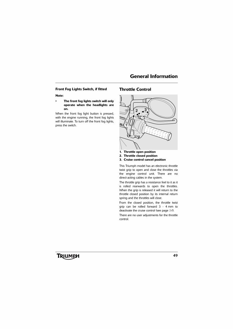
1. Throttle open position2. Throttle closed position3. Cruise control cancel position
This Triumph model has an electronic throttletwist grip to open and close the throttles viathe engine control unit. There are nodirect-acting cables in the system.
The throttle grip has a resistance feel to it as itis rolled rearwards to open the throttles.When the grip is released it will return to thethrottle closed position by its internal returnspring and the throttles will close.
From the closed position, the throttle twistgrip can be rolled forward 3 - 4 mm todeactivate the cruise control (see page 54).
There are no user adjustments for the throttlecontrol.
1
2 3
50
General Information
If there is a malfunction with the throttlecontrol the malfunction indicator light (MIL)becomes illuminated and one of thefollowing engine conditions may occur:
• MIL illuminated, restricted engineRPM and throttle movement;
• MIL illuminated, limp home modewith the engine at a fast idlecondition only;
• MIL illuminated, engine will notstart.
For all of the above conditions contact anauthorised Triumph dealer as soon aspossible to have the fault checked andrectified.
Brake UseAt low throttle opening (approximately 20°),the brakes and throttle can be used together.
At high throttle opening (greater than 20°), ifthe brakes are applied for greater than2 seconds the throttles will close and theengine speed will reduce. To return to normalthrottle operation, release the throttle control,release the brakes and then re-open thethrottle.
Cruise Control
WarningReduce speed and do not continue to ridefor longer than is necessary with themalfunction indicator light illuminated. Thefault may adversely affect engineperformance, exhaust emissions and fuelconsumption. Reduced engineperformance could cause a dangerousriding condition, leading to loss of controland an accident. Contact an authorisedTriumph dealer as soon as possible to havethe fault checked and rectified.
WarningCruise control must only be used whereyou can drive safely at a steady speed.
Cruise control should not be used whenriding in heavy traffic, on roads with sharp/blind bends or when they are slippery.
Using cruise control in heavy traffic, onroads with sharp/blind bends or when theyare slippery, may result in loss ofmotorcycle control and an accident.
WarningThis Triumph motorcycle should beoperated within the legal speed limits forthe particular road travelled. Operating amotorcycle at high speeds can bepotentially dangerous since the timeavailable to react to given traffic situationsis greatly reduced as speed increases.Always reduce speed in consideration ofweather and traffic conditions.

51
General Information
Note:
• Cruise control will not function ifthere is a malfunction with theABS system and the ABS warninglight is illuminated.
• If the ABS system is disabled (seepage 32), the ABS warning lightwill be illuminated and cruisecontrol WILL function.
The cruise control buttons are located on theright hand switch cube and can be operatedwith minimum movement by the rider.
Cruise control can be switched on or off atany time but it can not be activated until allthe conditions described on page 51 havebeen met.
Activating Cruise Control
Note:
• The cruise control indicator lightwill not illuminate until cruisecontrol has been activated bypressing SET/- on the adjustbutton.
To turn on the cruise control, press in the on/off button.
1. Cruise control ON/OFF button2. Cruise control adjust button, SET/-3. Cruise control adjust button, RES/+
WarningOnly operate this Triumph motorcycle athigh speed in closed-course on-roadcompetition or on closed-course racetracks.High-speed operation should only then beattempted by riders who have beeninstructed in the techniques necessary forhigh-speed riding and are familiar with themotorcycle's behaviour in all conditions.
High-speed operation in any othercircumstances is dangerous and will lead toloss of motorcycle control and an accident.
1
3
chdc_1
2
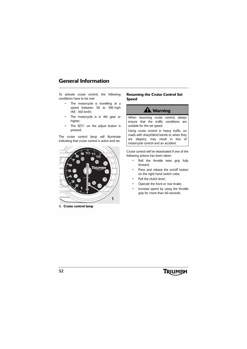
52
General Information
To activate cruise control, the followingconditions have to be met:
• The motorcycle is travelling at aspeed between 30 to 100 mph(48 - 160 kmh);
• The motorcycle is in 4th gear orhigher;
• The SET/- on the adjust button ispressed.
The cruise control lamp will illuminateindicating that cruise control is active and set.
1. Cruise control lamp
Resuming the Cruise Control Set Speed
Cruise control will be deactivated if one of thefollowing actions has been taken:
• Roll the throttle twist grip fullyforward;
• Press and release the on/off buttonon the right hand switch cube;
• Pull the clutch lever;
• Operate the front or rear brake;
• Increase speed by using the throttlegrip for more than 60 seconds.
MIN-1 x 1000
TC
1
WarningWhen resuming cruise control, alwaysensure that the traffic conditions aresuitable for the set speed.
Using cruise control in heavy traffic, onroads with sharp/blind bends or when theyare slippery, may result in loss ofmotorcycle control and an accident.
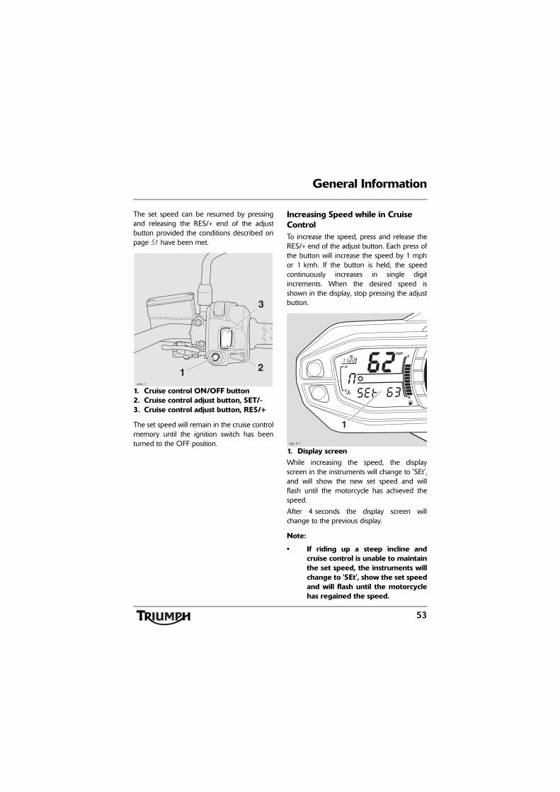
53
General Information
The set speed can be resumed by pressingand releasing the RES/+ end of the adjustbutton provided the conditions described onpage 51 have been met.
1. Cruise control ON/OFF button2. Cruise control adjust button, SET/-3. Cruise control adjust button, RES/+
The set speed will remain in the cruise controlmemory until the ignition switch has beenturned to the OFF position.
Increasing Speed while in Cruise ControlTo increase the speed, press and release theRES/+ end of the adjust button. Each press ofthe button will increase the speed by 1 mphor 1 kmh. If the button is held, the speedcontinuously increases in single digitincrements. When the desired speed isshown in the display, stop pressing the adjustbutton.
1. Display screenWhile increasing the speed, the displayscreen in the instruments will change to 'SEt',and will show the new set speed and willflash until the motorcycle has achieved thespeed.
After 4 seconds the display screen willchange to the previous display.
Note:
• If riding up a steep incline andcruise control is unable to maintainthe set speed, the instruments willchange to 'SEt', show the set speedand will flash until the motorcyclehas regained the speed.
1
3
chdc_1
2
cgjp_8_1
1
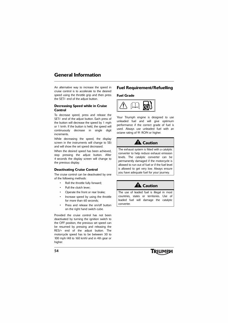
54
General Information
An alternative way to increase the speed incruise control is to accelerate to the desiredspeed using the throttle grip and then pressthe SET/- end of the adjust button.
Decreasing Speed while in Cruise ControlTo decrease speed, press and release theSET/- end of the adjust button. Each press ofthe button will decrease the speed by 1 mphor 1 kmh. If the button is held, the speed willcontinuously decrease in single digitincrements.
While decreasing the speed, the displayscreen in the instruments will change to SEtand will show the set speed decreased.
When the desired speed has been achieved,stop pressing the adjust button. After4 seconds the display screen will change tothe previous display.
Deactivating Cruise ControlThe cruise control can be deactivated by oneof the following methods:
• Roll the throttle fully forward;
• Pull the clutch lever;
• Operate the front or rear brake;
• Increase speed by using the throttlefor more than 60 seconds;
• Press and release the on/off buttonon the right hand switch cube.
Provided the cruise control has not beendeactivated by turning the ignition switch tothe OFF position, the previous set speed canbe resumed by pressing and releasing theRES/+ end of the adjust button. Themotorcycle speed has to be between 30 to100 mph (48 to 160 kmh) and in 4th gear orhigher.
Fuel Requirement/Refuelling
Fuel Grade
Your Triumph engine is designed to useunleaded fuel and will give optimumperformance if the correct grade of fuel isused. Always use unleaded fuel with anoctane rating of 91 RON or higher.
CautionThe exhaust system is fitted with a catalyticconverter to help reduce exhaust emissionlevels. The catalytic converter can bepermanently damaged if the motorcycle isallowed to run out of fuel or if the fuel levelis allowed to get very low. Always ensureyou have adequate fuel for your journey.
CautionThe use of leaded fuel is illegal in mostcountries, states or territories. Use ofleaded fuel will damage the catalyticconverter.
Pb

55
General Information
Fuel Tank Cap
1. Fuel tank cap2. Key
To open the fuel tank cap, lift up the flapcovering the lock itself. Insert the key into thelock and turn the key clockwise.
To close and lock the cap, push the cap downinto place with the key inserted, until the lock'clicks' into place. Withdraw the key and closethe key cover.
WarningTo help reduce hazards associated withrefuelling, always observe the followingfuel safety instructions:
Petrol (fuel) is highly flammable and can beexplosive under certain conditions. Whenrefuelling, turn the ignition switch to theOFF position.
Do not smoke.
Do not use a mobile telephone.
Make sure the refuelling area is wellventilated and free from any source offlame or sparks. This includes anyappliance with a pilot light.
Never fill the tank until the fuel level risesinto the filler neck. Heat from sunlight orother sources may cause the fuel toexpand and overflow creating a firehazard.
After refuelling always check that the fuelfiller cap is correctly closed and locked.
Because petrol (fuel) is highly flammable,any fuel leak or spillage, or any failure toobserve the safety advice given above willlead to a fire hazard, which could causedamage to property, injury to persons ordeath.
CautionClosing the cap without the key insertedwill damage the cap, tank and lockmechanism.
cbmm1
1
2

56
General Information
Filling the Fuel TankAvoid filling the tank in rainy or dustyconditions where airborne material cancontaminate the fuel.
Fill the fuel tank slowly to help preventspillage. Do not fill the tank to a level abovethe bottom of the filler neck. This will ensurethere is enough air space to allow for fuelexpansion if the fuel inside the tank expandsthrough absorption of heat from the engineor from direct sunlight.
1. Maximum fuel level2. Fuel filler neck3. Air space
After refuelling always check that the fuelfiller cap is correctly closed and locked.
Tool Kit, Handbook and the Triumph Accessory D-LockThe tool kit and handbook are locatedbeneath the pillion's seat.
If equipped, the D-lock is located beneath thepillion's seat (see page 61).
CautionContaminated fuel may cause damage tofuel system components.
1 2 3
cbdf
WarningOverfilling the tank can lead to fuelspillage.
If fuel is spilled, thoroughly clean up thespillage immediately and dispose of thematerials used safely.
Take care not to spill any fuel on theengine, exhaust pipes, tyres or any otherpart of the motorcycle.
Because fuel is highly flammable, any fuelleak or spillage, or any failure to observethe safety advice given above may lead toa fire hazard, which could cause damage toproperty and injury or death to persons.
Fuel spilled near to, or onto the tyres willreduce the tyre's ability to grip the road.This will result in a dangerous ridingcondition potentially causing loss ofmotorcycle control and an accident.

57
General Information
Stands
Side Stand
1. Side standThe motorcycle is equipped with a side standon which the motorcycle can be parked.
Note:
• When using the side stand, alwaysturn the handlebars fully to the leftand leave the motorcycle in firstgear.
Whenever the side stand is used, beforeriding, always ensure that the side stand isfully up after first sitting on the motorcycle.
For instructions on safe parking, refer to the'How to Ride the Motorcycle' section.
Centre Stand
1. Centre standTo set the motorcycle on the centre stand,step down firmly on the foot finder part ofthe stand, then lift the motorcycle up and tothe rear using the rear rack as a handhold.
For instructions on safe parking, refer to the'How to Ride the Motorcycle' section.
WarningThe motorcycle is fitted with an interlocksystem to prevent it from being riddenwith the side stand in the down position.
Never attempt to ride with the side standdown or interfere with the interlockmechanism as this will cause a dangerousriding condition leading to loss ofmotorcycle control and an accident.
1
chde
CautionDo not use body panels or the seat as ahand-hold when placing the motorcycle onthe centre stand as this will cause damage.
1
chdf

58
General Information
Seats
Seat CareTo prevent damage to the seat or seat cover,care must be taken not to drop or lean theseat against any surface which may damagethe seat or seat cover.
See page 127 for seat cleaning information.
Rear Seat
1. Seat lockThe seat lock is located on the rearmudguard, below the rear light unit. Toremove the seat, insert the ignition key intothe seat lock and turn it anti-clockwise whilepressing down on the rear of the seat. Thiswill release the seat from its lock and allow itto be slid rearwards for complete removalfrom the motorcycle.
CautionTo prevent damage to the seat or seatcover, care must be taken not to drop theseat. Do not lean the seat against themotorcycle or any surface which maydamage the seat or seat cover. Instead,place the seat, with the seat cover facingupwards, on a clean, flat surface which iscovered with a soft cloth.
Do not place any item on the seat whichmay cause damage or staining to the seatcover.
chdg
1

59
General Information
To refit the seat, engage the seat's two outerbrackets under the loops on the subframeand the two inner brackets to brackets on therider's seat. Gently push the seat forwardsand press down at the rear to engage in theseat lock.
1. Rear seat outer brackets2. Subframe loops3. Rear seat inner brackets4. Rider seat brackets
Rider's Seat
1. Rider’s seatTo remove the rider’s seat, remove the rearseat (see page 58).
Grasp the rider’s seat on either side, and slideit rearwards and upwards for completeremoval from the motorcycle.
To refit the seat, engage the seat's front railinto the bracket at the rear of the fuel tankand lower the rear rail in to the rear brackets.Push down firmly on the rear of the seat. Refitthe rear seat (see page 58).Warning
To prevent detachment of the seat duringriding, after fitting always grasp the seatand pull firmly upwards. If the seat is notcorrectly secured, it will detach from thelock. A loose or detached seat could causeloss of motorcycle control and an accident.
chdj
1
2
3 1
4chdh
1

60
General Information
Rider’s Seat Height Adjustment
1. Rider’s seat2. Front height adjuster3. Rear height adjuster4. Low seat height position (front
shown)5. High seat height position (front
shown)
The rider’s seat is adjustable for height byapproximately 20 mm.
To adjust the rider’s seat:
Remove the rider’s seat (see page 59).
Reposition both seat height adjusters to thehigher or lower position as required. Ensureboth adjuster rails are fully engaged in theirbrackets on the seat.
Refit the rider’s seat (see page 59).
4
42
5
3 1
chdi
WarningAlways adjust both seat height adjusters.Adjusting only one height adjuster mayprevent correct fitment of the seat.
Riding the motorcycle with an incorrectlyfitted seat may cause loss of control or anaccident.
WarningAfter adjusting the seat, operate themotorcycle in an area free from traffic togain familiarity with the new seat position.Riding the motorcycle with the seat in anunfamiliar position may cause loss ofcontrol or an accident.

61
General Information
Helmet HookA helmet can be secured to the motorcycleusing the helmet hook located on the lefthand side of the motorcycle, beneath therider's seat.
1. Helmet hookTo attach a helmet to the motorcycle, removethe rider's seat (see page 59) and loop thehelmet chin strap over the hook.
To secure the helmet, re-fit the seat and lockinto position (see page 59).
Triumph Accessory D-lock StorageSpace is provided under the rear seat to storea Triumph accessory D-lock (available fromyour Triumph dealer).
Secure the lock as follows:
Remove the rear seat (see page 58).
Release the strap and remove the handbookand tool kit.
Position the U-section of the lock to the rearmudguard tray support features, ensuring theopen end faces towards the front of themotorcycle.
Position the lock body into the rearmudguard tray as shown below.
1. Lock U-section2. Lock body
Fit the tool kit and handbook above theD-lock and secure using the tool kit strap.
Refit the rear seat (see page 59).
WarningNever ride the motorcycle with helmet(s)secured to the helmet hook. Riding themotorcycle with helmet(s) secured to thehelmet hook may cause the motorcycle tobecome unstable leading to loss of controland an accident.
1
cheb
21
chea

62
General Information
Electrical Accessory Socket
1. Electrical accessory socketAn electrical accessory socket is provided onthe motorcycle, located in front of the fueltank.
The socket will provide a 12 Volt electricalsupply. It is protected by a 10 Amp fuse,therefore items with a current draw greaterthan 10 Amps must not be plugged into thesocket.
A plug, suitable for use with the accessorysocket, is available from your authorisedTriumph dealer.
Handlebar AdjustmentThe handlebars are adjustable for reach byapproximately 20 mm.
Note:
• This procedure assumes thehandlebars are in the standardposition, as delivered from thefactory. If the handlebars havealready been adjusted asdescribed below, the bolt positionswill be reversed.
1
chdz
WarningIt is recommended to have handlebaradjustments carried out by a trainedtechnician of an authorised Triumph dealer.Handlebar adjustments carried out by atechnician who is not of an authorisedTriumph dealer may affect the handling,stability or other aspects of themotorcycle’s operation which may result inloss of motorcycle control and an accident.
WarningBefore starting work, ensure themotorcycle is stabilised and adequatelysupported. This will help prevent injury tothe operator or damage to the motorcycle.
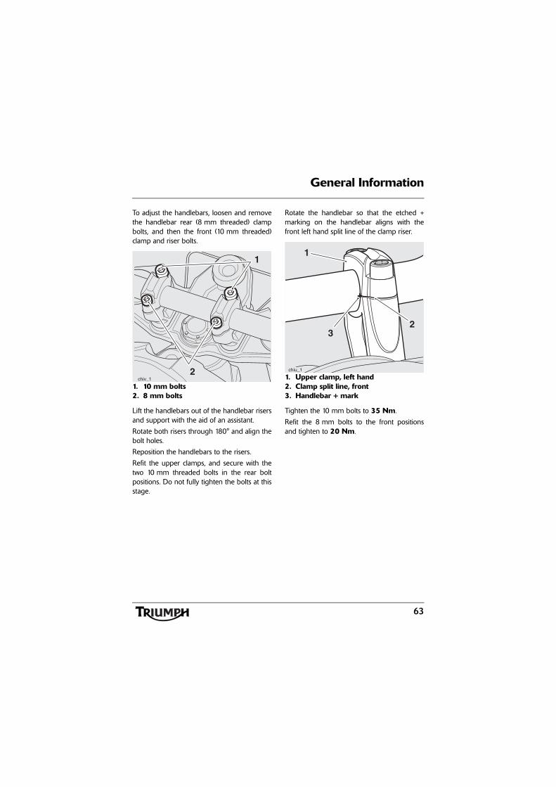
63
General Information
To adjust the handlebars, loosen and removethe handlebar rear (8 mm threaded) clampbolts, and then the front (10 mm threaded)clamp and riser bolts.
1. 10 mm bolts2. 8 mm bolts
Lift the handlebars out of the handlebar risersand support with the aid of an assistant.
Rotate both risers through 180° and align thebolt holes.
Reposition the handlebars to the risers.
Refit the upper clamps, and secure with thetwo 10 mm threaded bolts in the rear boltpositions. Do not fully tighten the bolts at thisstage.
Rotate the handlebar so that the etched +marking on the handlebar aligns with thefront left hand split line of the clamp riser.
1. Upper clamp, left hand2. Clamp split line, front3. Handlebar + mark
Tighten the 10 mm bolts to 35 Nm.
Refit the 8 mm bolts to the front positionsand tighten to 20 Nm.
2
1
chiv_1
23
1
chiu_1
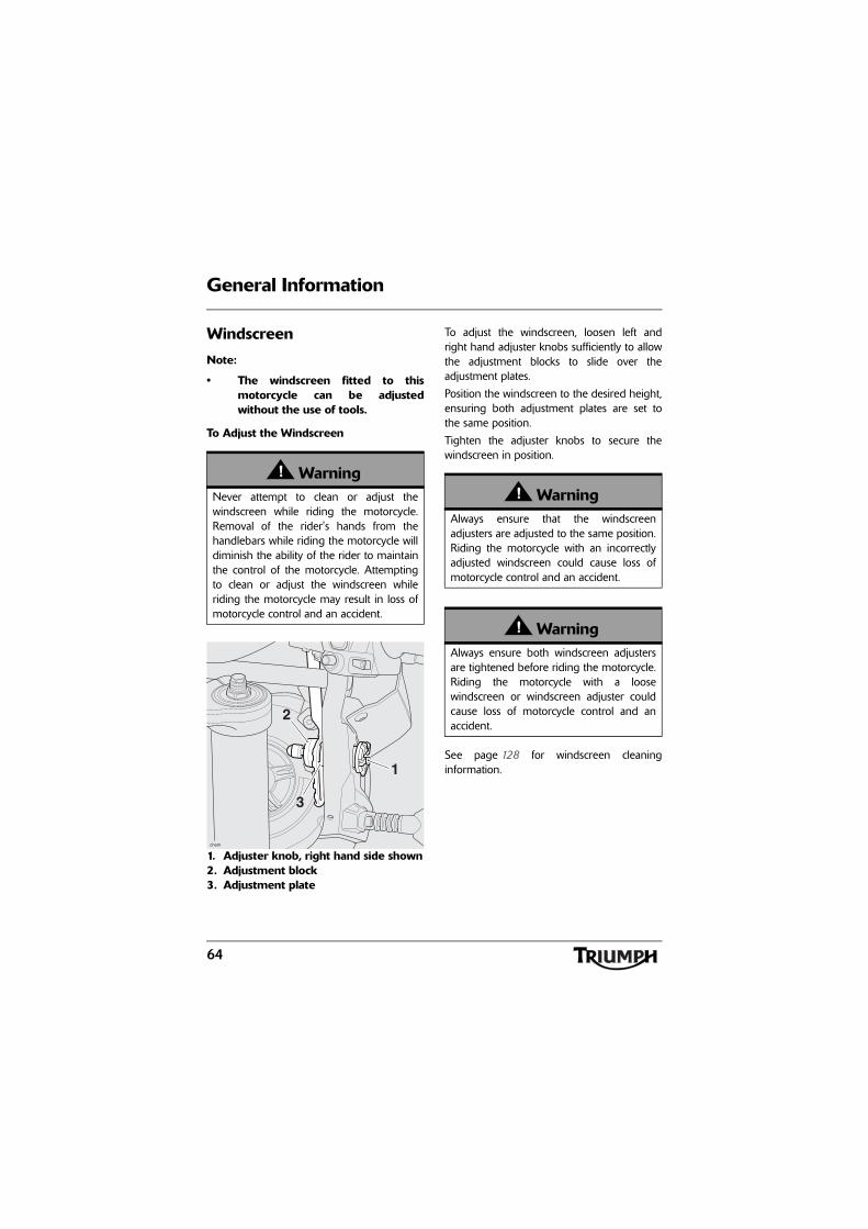
64
General Information
Windscreen
Note:
• The windscreen fitted to thismotorcycle can be adjustedwithout the use of tools.
To Adjust the Windscreen
1. Adjuster knob, right hand side shown2. Adjustment block3. Adjustment plate
To adjust the windscreen, loosen left andright hand adjuster knobs sufficiently to allowthe adjustment blocks to slide over theadjustment plates.
Position the windscreen to the desired height,ensuring both adjustment plates are set tothe same position.
Tighten the adjuster knobs to secure thewindscreen in position.
See page 128 for windscreen cleaninginformation.
WarningNever attempt to clean or adjust thewindscreen while riding the motorcycle.Removal of the rider's hands from thehandlebars while riding the motorcycle willdiminish the ability of the rider to maintainthe control of the motorcycle. Attemptingto clean or adjust the windscreen whileriding the motorcycle may result in loss ofmotorcycle control and an accident.
1
2
3
chem
WarningAlways ensure that the windscreenadjusters are adjusted to the same position.Riding the motorcycle with an incorrectlyadjusted windscreen could cause loss ofmotorcycle control and an accident.
WarningAlways ensure both windscreen adjustersare tightened before riding the motorcycle.Riding the motorcycle with a loosewindscreen or windscreen adjuster couldcause loss of motorcycle control and anaccident.

65
General Information
Running-In
Running-in is the name given to the processthat occurs during the first hours of a newvehicle's operation.
In particular, internal friction in the engine willbe higher when components are new. Lateron, when continued operation of the enginehas ensured that the components have'bedded in', this internal friction will begreatly reduced.
A period of careful running-in will ensurelower exhaust emissions, and will optimiseperformance, fuel economy and longevity ofthe engine and other motorcyclecomponents.
During the first 500 miles (800 kilometres):
• Do not use full throttle.
• Avoid high engine speeds at alltimes.
• Avoid riding at one constant enginespeed, whether fast or slow, for along period of time.
• Avoid aggressive starts, stops, andrapid accelerations, except in anemergency.
• Do not ride at speeds greater than3/4 of maximum engine speed.
From 500 to 1000 miles (800 to1500 kilometres):
• Engine speed can gradually beincreased to the rev limit for shortperiods.
Both during and after running-in has beencompleted:
• Do not over-rev the engine whencold.
• Do not let the engine labour. Alwaysdownshift before the engine beginsto 'struggle'.
• Do not ride with engine speedsunnecessarily high. Changing up agear helps reduce fuel consumption,reduces noise and helps to protectthe environment.
R.P.M.cboa

66
General Information
Safe Operation
Daily Safety Checks
Check the following items each day beforeyou ride. The time required is minimal, andthese checks will help ensure a safe, reliableride.
If any irregularities are found during thesechecks, refer to the Maintenance andAdjustment section or see your authorisedTriumph dealer for the action required toreturn the motorcycle to a safe operatingcondition.
Check:
Fuel: Adequate supply in tank, no fuel leaks(page 54).
Engine Oil: Correct level visible at sightglass. Add correct specification oil asrequired. No leaks from the engine or oilcooler (page 92).
Final Drive: No oil leaks (page 100).
Tyres/Wheels: Correct inflation pressures(when cold). Tread depth/wear, tyre/wheeldamage, punctures etc. (page 110).
Nuts, Bolts, Fasteners: Visually check thatsteering and suspension components, axles,and all controls are properly tightened orfastened. Inspect all areas for loose/damagedfixings.
Steering Action: Smooth but not loose fromlock to lock. No binding of any of the controlcables (page 104).
Brakes: Pull the brake lever and push thebrake pedal to check for correct resistance.Investigate any lever/pedal where the travel isexcessive before meeting resistance, or ifeither control feels spongy in operation(page 101).
ABS: Ensure that the ABS warning light doesnot remain illuminated at speeds above6 mph (10 kmh) when moving off (page 39).
Brake Pads: There should be more than1.5 mm of friction material remaining on allthe pads (page 101).
Brake Fluid Levels: No brake and clutchfluid leakage. Brake fluid levels must bebetween the MAX and MIN marks on bothreservoirs (page 103).
Front Forks: Smooth action. No leaks fromfork seals (page 106).
WarningFailure to perform these checks every daybefore you ride may result in seriousmotorcycle damage or an accident causingserious injury or death.
cbob

67
General Information
Throttle: Throttle grip free play 2 - 3 mm.Ensure that the throttle grip returns to theidle position without sticking (page 49).
Clutch Fluid Level: No brake and clutchfluid leakage. The clutch fluid level must bebetween the MAX and MIN marks on thereservoir (page 99).
Coolant: No coolant leakage. Check thecoolant level in the expansion tank (when theengine is cold) (page 95).
Electrical Equipment: All lights and thehorn function correctly (page 42).
Engine Stop: Stop switch turns the engineoff (page 70).
Stands: Returns to the fully up position byspring tension. Return springs not weak ordamaged (page 57).

General Information
68
This page intentionally left blank

How to Ride the Motorcycle
69
HOW TO RIDE THE MOTORCYCLE
Table of ContentsTo Stop the Engine . . . . . . . . . . . . . . . . . . . . . . . . . . . . . . . . . . . . . . . . . . . . . . . . . . . . . . . . . . . 70
To Start the Engine . . . . . . . . . . . . . . . . . . . . . . . . . . . . . . . . . . . . . . . . . . . . . . . . . . . . . . . . . . . 70
Moving Off . . . . . . . . . . . . . . . . . . . . . . . . . . . . . . . . . . . . . . . . . . . . . . . . . . . . . . . . . . . . . . . . . 72
Changing Gears . . . . . . . . . . . . . . . . . . . . . . . . . . . . . . . . . . . . . . . . . . . . . . . . . . . . . . . . . . . . . 72
Braking . . . . . . . . . . . . . . . . . . . . . . . . . . . . . . . . . . . . . . . . . . . . . . . . . . . . . . . . . . . . . . . . . . . . 73
ABS (Anti-Lock Brake System) . . . . . . . . . . . . . . . . . . . . . . . . . . . . . . . . . . . . . . . . . . . . . . 75
Parking . . . . . . . . . . . . . . . . . . . . . . . . . . . . . . . . . . . . . . . . . . . . . . . . . . . . . . . . . . . . . . . . . . . . 76
Considerations for High-Speed Operation . . . . . . . . . . . . . . . . . . . . . . . . . . . . . . . . . . . . . . . . 77
General . . . . . . . . . . . . . . . . . . . . . . . . . . . . . . . . . . . . . . . . . . . . . . . . . . . . . . . . . . . . . . . . 78Steering . . . . . . . . . . . . . . . . . . . . . . . . . . . . . . . . . . . . . . . . . . . . . . . . . . . . . . . . . . . . . . . . 78Luggage. . . . . . . . . . . . . . . . . . . . . . . . . . . . . . . . . . . . . . . . . . . . . . . . . . . . . . . . . . . . . . . . 78Brakes . . . . . . . . . . . . . . . . . . . . . . . . . . . . . . . . . . . . . . . . . . . . . . . . . . . . . . . . . . . . . . . . . 78Tyres . . . . . . . . . . . . . . . . . . . . . . . . . . . . . . . . . . . . . . . . . . . . . . . . . . . . . . . . . . . . . . . . . . . 78Fuel. . . . . . . . . . . . . . . . . . . . . . . . . . . . . . . . . . . . . . . . . . . . . . . . . . . . . . . . . . . . . . . . . . . . 78Engine Oil . . . . . . . . . . . . . . . . . . . . . . . . . . . . . . . . . . . . . . . . . . . . . . . . . . . . . . . . . . . . . . 78Final Drive Oil . . . . . . . . . . . . . . . . . . . . . . . . . . . . . . . . . . . . . . . . . . . . . . . . . . . . . . . . . . . 79Coolant . . . . . . . . . . . . . . . . . . . . . . . . . . . . . . . . . . . . . . . . . . . . . . . . . . . . . . . . . . . . . . . . 79Electrical Equipment . . . . . . . . . . . . . . . . . . . . . . . . . . . . . . . . . . . . . . . . . . . . . . . . . . . . . . 79Miscellaneous . . . . . . . . . . . . . . . . . . . . . . . . . . . . . . . . . . . . . . . . . . . . . . . . . . . . . . . . . . . 79

70
How to Ride the Motorcycle
To Stop the Engine
1. Engine stop switch2. Starter button3. Neutral indicator light4. ON position5. Ignition switch
Close the throttle completely.
Select neutral.
Turn the ignition switch off.
Select first gear.
Support the motorcycle on a firm, levelsurface with the side or centre stand.
Lock the steering.
To Start the EngineCheck that the engine stop switch is in theRUN position.
Ensure the transmission is in neutral.
Turn the ignition switch on.
Note:
• When the ignition is switched on,the tachometer needle will quicklysweep from zero to maximum andthen return to zero. Theinstrument warning lights willilluminate and will then go off(except those which normallyremain on until the engine starts -see 'Warning Lights' on page 36).It is not necessary to wait for theneedle to return to zero beforestarting the engine.
PU
SH
P
OFF
ON
3
52
14
CautionThe engine should normally be stopped byturning the ignition switch to theOFF position. The engine stop switch is foremergency use only. Do not leave theignition switched on with the enginestopped. Electrical damage may result.
71
How to Ride the Motorcycle
• A transponder is fitted within thekey to turn off the engineimmobiliser. To ensure theimmobiliser functions correctly,always have only one of theignition keys near the ignitionswitch. Having two ignition keysnear the switch may interrupt thesignal between the transponderand the engine immobiliser. In thissituation the engine immobiliserwill remain active until one of theignition keys is removed.
• In very cold conditions, part openthe throttle to aid cold starting.Return it to the closed positiononce the engine has started.
Pull the clutch lever fully into the handlebar.
Leaving the throttle fully closed, push thestarter button until the engine starts.
• The motorcycle is equipped withstarter lockout switches. The switchesprevent the electric starter fromoperating when the transmission isnot in neutral with the side standdown.
• If the side stand is extended whilstthe engine is running, and thetransmission is not in neutral thenthe engine will stop regardless ofclutch position.
WarningNever start the engine or run the engine ina confined area. Exhaust fumes arepoisonous and can cause loss ofconsciousness and death within a shortperiod of time. Always operate yourmotorcycle in the open-air or in an areawith adequate ventilation.
CautionDo not operate the starter continuously formore than 5 seconds as the starter motorwill overheat and the battery will becomedischarged. Wait 15 seconds between eachoperation of the starter to allow for coolingand recovery of battery power.
Do not let the engine idle for long periodsas this may lead to overheating which willcause damage to the engine.
CautionIf the low oil pressure warning/low oil levelwarning light illuminates after starting theengine, stop the engine immediately andinvestigate the cause. Running the enginewith low oil pressure will cause severeengine damage.
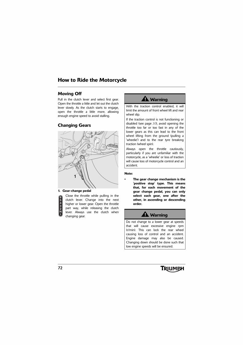
72
How to Ride the Motorcycle
Moving OffPull in the clutch lever and select first gear.Open the throttle a little and let out the clutchlever slowly. As the clutch starts to engage,open the throttle a little more, allowingenough engine speed to avoid stalling.
Changing Gears
1. Gear-change pedalClose the throttle while pulling in theclutch lever. Change into the nexthigher or lower gear. Open the throttlepart way, while releasing the clutchlever. Always use the clutch whenchanging gear.
Note:
• The gear change mechanism is the'positive stop' type. This meansthat, for each movement of thegear change pedal, you can onlyselect each gear, one after theother, in ascending or descendingorder.
1
65432N1
WarningWith the traction control enabled, it willlimit the amount of front wheel lift and rearwheel slip.
If the traction control is not functioning ordisabled (see page 30), avoid opening thethrottle too far or too fast in any of thelower gears as this can lead to the frontwheel lifting from the ground (pulling a'wheelie') and to the rear tyre breakingtraction (wheel spin).
Always open the throttle cautiously,particularly if you are unfamiliar with themotorcycle, as a 'wheelie' or loss of tractionwill cause loss of motorcycle control and anaccident.
WarningDo not change to a lower gear at speedsthat will cause excessive engine rpm(r/min). This can lock the rear wheelcausing loss of control and an accident.Engine damage may also be caused.Changing down should be done such thatlow engine speeds will be ensured.
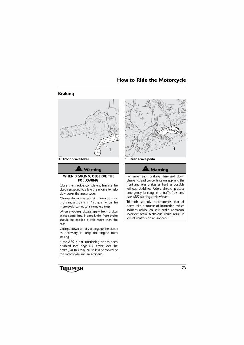
73
How to Ride the Motorcycle
Braking
1. Front brake lever 1. Rear brake pedal
WarningWHEN BRAKING, OBSERVE THE
FOLLOWING:Close the throttle completely, leaving theclutch engaged to allow the engine to helpslow down the motorcycle.
Change down one gear at a time such thatthe transmission is in first gear when themotorcycle comes to a complete stop.
When stopping, always apply both brakesat the same time. Normally the front brakeshould be applied a little more than therear.
Change down or fully disengage the clutchas necessary to keep the engine fromstalling.
If the ABS is not functioning or has beendisabled (see page 32), never lock thebrakes, as this may cause loss of control ofthe motorcycle and an accident.
1chex
WarningFor emergency braking, disregard downchanging, and concentrate on applying thefront and rear brakes as hard as possiblewithout skidding. Riders should practiceemergency braking in a traffic-free area(see ABS warnings below/over).
Triumph strongly recommends that allriders take a course of instruction, whichincludes advice on safe brake operation.Incorrect brake technique could result inloss of control and an accident.
1
chgo

74
How to Ride the Motorcycle
WarningFor your safety, always exercise extremecaution when braking (whether or not ABSis fitted), accelerating or turning as anyincautious action can cause loss of controland an accident. Independent use of thefront or rear brakes reduces overallbraking performance. Extreme brakingmay cause either wheel to lock, reducingcontrol of the motorcycle and causing anaccident (see ABS warnings below).
When possible, reduce speed or brakebefore entering a turn as closing thethrottle or braking in mid-turn may causewheel slip leading to loss of control and anaccident.
When riding in wet or rainy conditions, oron loose surfaces, the ability to manoeuvreand stop will be reduced. All of youractions should be smooth under theseconditions. Sudden acceleration, braking orturning may cause loss of control and anaccident.
WarningWhen descending a long, steep gradient,use engine braking by down changing anduse the brakes intermittently. Continuousbrake application can overheat the brakesand reduce their effectiveness.
Riding with your foot on the brake pedalor your hands on the brake lever mayactuate the brake light, giving a falseindication to other road users. It may alsooverheat the brake, reducing brakingeffectiveness.
Do not coast with the engine switched off,and do not tow the motorcycle. Thetransmission is pressure-lubricated onlywhen the engine is running. Inadequatelubrication may cause damage or seizureof the transmission, which can lead tosudden loss of motorcycle control and anaccident.
WarningWhen using the motorcycle on loose, wet,or muddy roads, braking effectiveness willbe reduced by dust, mud or moisturecollecting on the brakes. Always brakeearlier in these conditions to ensure brakesurfaces are cleaned by the braking action.Riding the motorcycle with brakescontaminated with dust, mud or moisturemay cause loss of control and an accident.
75
How to Ride the Motorcycle
ABS (Anti-Lock Brake System) ABS Warning LightWhen the ignition switch isturned to the ON position, it isnormal for the ABS warning
light to flash on and off (see page 39). If theABS warning light is constantly illuminated itindicates that the ABS function is notavailable because:
• the ABS has been disabled by therider (see page 32);
• the ABS has a malfunction thatrequires investigation.
If the indicator light becomes illuminatedwhile riding, it indicates that the ABS has amalfunction that requires investigation.
Note:
• Normally, the rider will perceiveABS operation as a harder feel or apulsation of the brake lever andpedal. As the ABS is not anintegrated braking system and itdoes not control both the frontand rear brake at the same time,this pulsation may be felt in thelever, the pedal or both.
• The ABS may be activated bysudden upward or downwardchanges in the road surface.
WarningABS prevents the wheels from locking,therefore maximising the effectiveness ofthe braking system in emergencies andwhen riding on slippery surfaces. Thepotentially shorter braking distances ABSallows under certain conditions are not asubstitute for good riding practice.
Always ride within the legal speed limit.
Never ride without due care and attentionand always reduce speed in considerationof weather, road and traffic conditions.
Take care when cornering. If the brakes areapplied in a corner, ABS will not be able tocounteract the weight and momentum ofthe motorcycle. This can result in loss ofcontrol and an accident.
Under some circumstances it is possiblethat a motorcycle equipped with ABS mayrequire a longer stopping distance than anequivalent motorcycle without ABS.

76
How to Ride the Motorcycle
Parking
Select neutral and turn the ignition switch tothe OFF position.
Lock the steering to help prevent theft.
Always park on a firm, level surface toprevent the motorcycle from falling. This isparticularly important when parking off road.
When parking on a hill, always park facinguphill to prevent the motorcycle from rollingoff the stand. Engage first gear to prevent themotorcycle from moving.
On a lateral (sideways) incline, always parksuch that the incline naturally pushes themotorcycle towards the sidestand.
Do not park on a lateral (sideways) incline ofgreater than 6° and never park facingdownhill.
Note:
• When parking near traffic at night,or when parking in a locationwhere parking lights are requiredby law, leave the tail, licence plateand position lights on by turningthe ignition switch to P (PARK).
WarningIf the ABS is not functioning, has beendisabled by the rider (see page 32), thebrake system will continue to function as anon-ABS braking system. Do not continueto ride for longer than is necessary with theindicator light illuminated. In the event of afault, contact an authorised Triumph dealeras soon as possible to have the faultchecked and rectified. In this situation,braking too hard will cause the wheels tolock resulting in loss of control and anaccident.
WarningThe ABS warning light will illuminate whenthe rear wheel is driven at high speed formore than 30 seconds when themotorcycle is on a stand. This reaction isnormal.
When the ignition is switched off and themotorcycle is re-started, the warning lightwill illuminate until the motorcycle reachesa speed exceeding 19 mph (30 km/h).
WarningThe ABS computer operates by comparingthe relative speed of the front and rearwheels. Use of non-recommended tyrescan affect wheel speed and cause the ABSfunction not to operate, potentially leadingto loss of control and an accident inconditions where the ABS would normallyfunction.
ccms_1

77
How to Ride the Motorcycle
Do not leave the switch in the P position forlong periods of time as this will discharge thebattery.
Considerations for High-Speed Operation
WarningDo not park on a soft or on a steeplyinclined surface. Parking under theseconditions may cause the motorcycle to fallover causing damage to property andpersonal injury.
WarningPetrol is extremely flammable and can beexplosive under certain conditions. Ifparking inside a garage or other structure,be sure it is well ventilated and themotorcycle is not close to any source offlame or sparks. This includes anyappliance with a pilot light.
Failure to follow the above advice maycause a fire resulting in damage toproperty or personal injury.
WarningThe engine and exhaust system will be hotafter riding. DO NOT park wherepedestrians and children are likely to touchthe motorcycle.
Touching any part of the engine or exhaustsystem when hot may cause unprotectedskin to become burnt.
WarningThis Triumph motorcycle should beoperated within the legal speed limits forthe particular road travelled. Operating amotorcycle at high speeds can bepotentially dangerous since the timeavailable to react to given traffic situationsis greatly reduced as road speed increases.Always reduce speed in consideration ofweather and traffic conditions.
WarningOnly operate this Triumph motorcycle athigh speed in closed-course on-roadcompetition or on closed-course racetracks.High-speed operation should only then beattempted by riders who have beeninstructed in the techniques necessary forhigh-speed riding and are familiar with themotorcycle's characteristics in allconditions.
High-speed operation in any othercircumstances is dangerous and will lead toloss of motorcycle control and an accident.

78
How to Ride the Motorcycle
GeneralEnsure the motorcycle has been maintainedaccording to the scheduled maintenancechart.
SteeringCheck that the handlebar turns smoothlywithout excessive free play or tight spots.Ensure that the control cables do not restrictthe steering in any way.
LuggageMake certain that any luggage containers areclosed, locked and securely fitted to themotorcycle.
BrakesCheck that the front and rear brakes arefunctioning properly.
TyresHigh-speed operation is hard on tyres, andtyres that are in good condition are crucial toriding safely. Examine their overall condition,inflate to the correct pressure (when the tyresare cold), and check the wheel balance.Securely fit the valve caps after checking tyrepressures. Observe the information given inthe Maintenance and Specification sectionson tyre checking and tyre safety.
FuelHave sufficient fuel for the increased fuelconsumption that will result from high-speedoperation.
Engine OilMake certain that the engine oil level iscorrect. Ensure that the correct grade andtype of oil is used when topping up.
WarningThe handling characteristics of amotorcycle at high speed may vary fromthose you are familiar with at legal roadspeeds. Do not attempt high-speedoperation unless you have receivedsufficient training and have the requiredskills as a serious accident may result fromincorrect operation.
WarningThe items listed are extremely importantand must never be neglected. A problem,which may not be noticed at normaloperating speeds, may be greatlyexaggerated at high speeds.
CautionThe exhaust system is fitted with a catalyticconverter to help reduce exhaust emissionlevels. The catalytic converter can bepermanently damaged if the motorcycle isallowed to run out of fuel or if the fuel levelis allowed to get very low. Always ensureyou have adequate fuel for your journey.

79
How to Ride the Motorcycle
Final Drive OilMake certain that the final drive oil level iscorrect. Ensure that the correct grade andtype of oil is used when topping up.
CoolantCheck that the coolant level is at the upperlevel line in the expansion tank. (Alwayscheck the level with the engine cold.)
Electrical EquipmentMake certain that the headlight, rear/brakelight, direction indicators, horn, etc. all workproperly.
MiscellaneousVisually check that all fixings are tight.
How to Ride the Motorcycle
80
This page intentionally left blank

81
Accessories and Loading
ACCESSORIES AND LOADINGThe addition of accessories and carriage ofadditional weight can affect the motorcycle'shandling characteristics causing changes instability and necessitating a reduction inspeed. The following information has beenprepared as a guide to the potential hazardsof adding accessories to a motorcycle andcarrying passengers and additional loads.
Adjust the headlight aim to compensate foradditional loads, see page 122.
WarningIncorrect loading may result in an unsaferiding condition leading to an accident.
Always ensure any loads carried are evenlydistributed on both sides of the motorcycle.Ensure that the load is correctly securedsuch that it will not move around while themotorcycle is in motion.
Always check the load security regularly(though not while the motorcycle is inmotion) and ensure that the load does notextend beyond the rear of the motorcycle.
Never exceed the maximum vehicleloading weight of 222 kg (489 lb).
This maximum loading weight is made upfrom the combined weight of the rider,passenger, any accessories fitted and anyload carried.
WarningDo not install accessories or carry luggagethat impairs the control of the motorcycle.Make sure that you have not adverselyaffected the visibility of any lightingcomponent, road clearance, bankingcapability (i.e. lean angle), controloperation, wheel travel, front forkmovement, visibility in any direction, orany other aspect of the motorcycle'soperation.
WarningThis motorcycle must not be operatedabove the legal road speed limit except inauthorised closed-course conditions.
WarningOnly operate this Triumph motorcycle athigh speed in closed-course on-roadcompetition or on closed-course racetracks.High-speed operation should only then beattempted by riders who have beeninstructed in the techniques necessary forhigh-speed riding and are familiar with themotorcycle's characteristics in allconditions.
High-speed operation in any othercircumstances is dangerous and will lead toloss of motorcycle control and an accident.

82
Accessories and Loading
WarningYour passenger should be instructed thathe or she can cause loss of motorcyclecontrol by making sudden movements orby adopting an incorrect seated position.
The rider should instruct the passenger asfollows:
• It is important that the passengersits still while the motorcycle is inmotion and does not interferewith the operation of themotorcycle.
• To keep his or her feet on thepassenger footrests and to firmlyhold onto the grab handles or therider's waist or hips.
• Advise the passenger to lean withthe rider when travelling aroundcorners and not to lean unless therider does so.
WarningDo not carry animals on your motorcycle.
An animal could make sudden andunpredictable movements that could leadto loss of motorcycle control and anaccident.
WarningThe handling and braking capabilities of amotorcycle will be affected by the presenceof a passenger. The rider must makeallowances for these changes whenoperating the motorcycle with a passengerand should not attempt such operationunless trained to do so and withoutbecoming familiar and comfortable withthe changes in motorcycle operatingcharacteristics that this brings about.
Motorcycle operation without makingallowances for the presence of a passengercould lead to loss of motorcycle controland an accident.
WarningNever attempt to store any items betweenthe frame and the fuel tank. This canrestrict the steering and will cause loss ofcontrol leading to an accident.
Weight attached to the handlebar or frontfork will increase the mass of the steeringassembly and can result in loss of steeringcontrol leading to an accident.
XX

83
Accessories and Loading
WarningDo not carry a passenger unless he or sheis tall enough to reach the footrestsprovided.
A passenger who is not tall enough toreach the footrests will be unable to sitsecurely on the motorcycle and may causeinstability leading to loss of control and anaccident.
WarningNever ride an accessory equippedmotorcycle, or a motorcycle carrying apayload of any kind, at speeds above80 mph (130 km/h). In either/both ofthese conditions, speeds in excess of80 mph (130 km/h) should not beattempted even where the legal speedlimit permits this.
The presence of accessories and/orpayload will cause changes in the stabilityand handling of the motorcycle.
Failure to allow for changes in motorcyclestability may lead to loss of control or anaccident.
Remember that the 80 mph (130 km/h)absolute limit will be reduced by the fittingof non-approved accessories, incorrectloading, worn tyres, overall motorcyclecondition and poor road or weatherconditions.
WarningIf the passenger seat is used to carry smallobjects, they must not exceed 5 kg inweight, must not impair control of themotorcycle, must be securely attached andmust not extend beyond the rear or sidesof the motorcycle.
Carriage of objects in excess of 5 kg inweight, that are insecure, impair control orextend beyond the rear or sides of themotorcycle may lead to loss of motorcyclecontrol and an accident.
Even if small objects are correctly loadedonto the rear seat, the maximum speed ofthe motorcycle must be reduced to80 mph (130 km/h).
84
Accessories and Loading
This page intentionally left blank

Maintenance and Adjustment
85
MAINTENANCE AND ADJUSTMENT
Table of ContentsScheduled Maintenance. . . . . . . . . . . . . . . . . . . . . . . . . . . . . . . . . . . . . . . . . . . . . . . . . . . . . . . 88
Engine Oil . . . . . . . . . . . . . . . . . . . . . . . . . . . . . . . . . . . . . . . . . . . . . . . . . . . . . . . . . . . . . . . . . . 92
Oil Level Inspection. . . . . . . . . . . . . . . . . . . . . . . . . . . . . . . . . . . . . . . . . . . . . . . . . . . . . . . 92Oil and Oil Filter Change . . . . . . . . . . . . . . . . . . . . . . . . . . . . . . . . . . . . . . . . . . . . . . . . . . 93Disposal of Used Engine Oil and Oil Filters . . . . . . . . . . . . . . . . . . . . . . . . . . . . . . . . . . . . 94Oil Specification and Grade . . . . . . . . . . . . . . . . . . . . . . . . . . . . . . . . . . . . . . . . . . . . . . . . 95
Cooling System. . . . . . . . . . . . . . . . . . . . . . . . . . . . . . . . . . . . . . . . . . . . . . . . . . . . . . . . . . . . . . 95
Corrosion Inhibitors . . . . . . . . . . . . . . . . . . . . . . . . . . . . . . . . . . . . . . . . . . . . . . . . . . . . . . . 95Coolant Level Inspection . . . . . . . . . . . . . . . . . . . . . . . . . . . . . . . . . . . . . . . . . . . . . . . . . . . 96Coolant Level Adjustment. . . . . . . . . . . . . . . . . . . . . . . . . . . . . . . . . . . . . . . . . . . . . . . . . . 97Coolant Change . . . . . . . . . . . . . . . . . . . . . . . . . . . . . . . . . . . . . . . . . . . . . . . . . . . . . . . . . 97Radiator and Hoses . . . . . . . . . . . . . . . . . . . . . . . . . . . . . . . . . . . . . . . . . . . . . . . . . . . . . . . 98Inspection. . . . . . . . . . . . . . . . . . . . . . . . . . . . . . . . . . . . . . . . . . . . . . . . . . . . . . . . . . . . . . . 98
Clutch . . . . . . . . . . . . . . . . . . . . . . . . . . . . . . . . . . . . . . . . . . . . . . . . . . . . . . . . . . . . . . . . . . . . . 99
Clutch Fluid Level Inspection and Adjustment. . . . . . . . . . . . . . . . . . . . . . . . . . . . . . . . . . 99
Final Drive Unit . . . . . . . . . . . . . . . . . . . . . . . . . . . . . . . . . . . . . . . . . . . . . . . . . . . . . . . . . . . . . 100
Final Drive Oil Level Adjustment . . . . . . . . . . . . . . . . . . . . . . . . . . . . . . . . . . . . . . . . . . . 100
Brakes . . . . . . . . . . . . . . . . . . . . . . . . . . . . . . . . . . . . . . . . . . . . . . . . . . . . . . . . . . . . . . . . . . . . .101
Brake Wear Inspection . . . . . . . . . . . . . . . . . . . . . . . . . . . . . . . . . . . . . . . . . . . . . . . . . . . .101Breaking-in New Brake Pads and Discs . . . . . . . . . . . . . . . . . . . . . . . . . . . . . . . . . . . . . . .101Brake Pad Wear Compensation . . . . . . . . . . . . . . . . . . . . . . . . . . . . . . . . . . . . . . . . . . . . 102Disc Brake Fluid . . . . . . . . . . . . . . . . . . . . . . . . . . . . . . . . . . . . . . . . . . . . . . . . . . . . . . . . . 102Front Brake Fluid Level Inspection and Adjustment. . . . . . . . . . . . . . . . . . . . . . . . . . . . . 103Rear Brake Fluid Inspection and Adjustment . . . . . . . . . . . . . . . . . . . . . . . . . . . . . . . . . . 103Brake Light Switches . . . . . . . . . . . . . . . . . . . . . . . . . . . . . . . . . . . . . . . . . . . . . . . . . . . . . 104
Steering/Wheel Bearings . . . . . . . . . . . . . . . . . . . . . . . . . . . . . . . . . . . . . . . . . . . . . . . . . . . . . 104
Steering Inspection . . . . . . . . . . . . . . . . . . . . . . . . . . . . . . . . . . . . . . . . . . . . . . . . . . . . . . 104Inspecting the Steering (Headstock) Bearings for Free Play . . . . . . . . . . . . . . . . . . . . . . 105Wheel Bearings Inspection . . . . . . . . . . . . . . . . . . . . . . . . . . . . . . . . . . . . . . . . . . . . . . . . 105

Maintenance and Adjustment
86
Front Suspension . . . . . . . . . . . . . . . . . . . . . . . . . . . . . . . . . . . . . . . . . . . . . . . . . . . . . . . . . . . 106
Front Fork Inspection. . . . . . . . . . . . . . . . . . . . . . . . . . . . . . . . . . . . . . . . . . . . . . . . . . . . . 106Front Suspension Settings . . . . . . . . . . . . . . . . . . . . . . . . . . . . . . . . . . . . . . . . . . . . . . . . . 106Spring Pre-Load Adjustment. . . . . . . . . . . . . . . . . . . . . . . . . . . . . . . . . . . . . . . . . . . . . . . 106Front Suspension Setting Chart . . . . . . . . . . . . . . . . . . . . . . . . . . . . . . . . . . . . . . . . . . . . 107
Rear Suspension . . . . . . . . . . . . . . . . . . . . . . . . . . . . . . . . . . . . . . . . . . . . . . . . . . . . . . . . . . . . 107
Rear Suspension Setting Chart . . . . . . . . . . . . . . . . . . . . . . . . . . . . . . . . . . . . . . . . . . . . . 107Rear Suspension Adjustment . . . . . . . . . . . . . . . . . . . . . . . . . . . . . . . . . . . . . . . . . . . . . . 108Spring Pre-Load Adjustment. . . . . . . . . . . . . . . . . . . . . . . . . . . . . . . . . . . . . . . . . . . . . . . 108Rebound Damping Adjustment . . . . . . . . . . . . . . . . . . . . . . . . . . . . . . . . . . . . . . . . . . . . 109
Tyres . . . . . . . . . . . . . . . . . . . . . . . . . . . . . . . . . . . . . . . . . . . . . . . . . . . . . . . . . . . . . . . . . . . . . .110
Tyre Inflation Pressures . . . . . . . . . . . . . . . . . . . . . . . . . . . . . . . . . . . . . . . . . . . . . . . . . . . .111Tyre Wear. . . . . . . . . . . . . . . . . . . . . . . . . . . . . . . . . . . . . . . . . . . . . . . . . . . . . . . . . . . . . . .112Minimum Recommended Tread Depth . . . . . . . . . . . . . . . . . . . . . . . . . . . . . . . . . . . . . . .112Tyre Replacement . . . . . . . . . . . . . . . . . . . . . . . . . . . . . . . . . . . . . . . . . . . . . . . . . . . . . . . .113
Battery . . . . . . . . . . . . . . . . . . . . . . . . . . . . . . . . . . . . . . . . . . . . . . . . . . . . . . . . . . . . . . . . . . . . .115
Battery Removal. . . . . . . . . . . . . . . . . . . . . . . . . . . . . . . . . . . . . . . . . . . . . . . . . . . . . . . . . .116Battery Disposal . . . . . . . . . . . . . . . . . . . . . . . . . . . . . . . . . . . . . . . . . . . . . . . . . . . . . . . . . .116Battery Maintenance . . . . . . . . . . . . . . . . . . . . . . . . . . . . . . . . . . . . . . . . . . . . . . . . . . . . . .116Battery Discharge . . . . . . . . . . . . . . . . . . . . . . . . . . . . . . . . . . . . . . . . . . . . . . . . . . . . . . . .117Battery Maintenance During Storage and Infrequent Use of the Motorcycle . . . . . . . . .117Battery Charging . . . . . . . . . . . . . . . . . . . . . . . . . . . . . . . . . . . . . . . . . . . . . . . . . . . . . . . . .118Battery Installation . . . . . . . . . . . . . . . . . . . . . . . . . . . . . . . . . . . . . . . . . . . . . . . . . . . . . . . .118
Fuse Boxes . . . . . . . . . . . . . . . . . . . . . . . . . . . . . . . . . . . . . . . . . . . . . . . . . . . . . . . . . . . . . . . . .119
Main Fuse Boxes . . . . . . . . . . . . . . . . . . . . . . . . . . . . . . . . . . . . . . . . . . . . . . . . . . . . . . . . .119ABS Fuse Box . . . . . . . . . . . . . . . . . . . . . . . . . . . . . . . . . . . . . . . . . . . . . . . . . . . . . . . . . . .119Fuse Identification . . . . . . . . . . . . . . . . . . . . . . . . . . . . . . . . . . . . . . . . . . . . . . . . . . . . . . . 120ABS fuse box. . . . . . . . . . . . . . . . . . . . . . . . . . . . . . . . . . . . . . . . . . . . . . . . . . . . . . . . . . . .121Main fuse. . . . . . . . . . . . . . . . . . . . . . . . . . . . . . . . . . . . . . . . . . . . . . . . . . . . . . . . . . . . . . .121
Headlights . . . . . . . . . . . . . . . . . . . . . . . . . . . . . . . . . . . . . . . . . . . . . . . . . . . . . . . . . . . . . . . . . .121
Headlights . . . . . . . . . . . . . . . . . . . . . . . . . . . . . . . . . . . . . . . . . . . . . . . . . . . . . . . . . . . . . .121Headlight Adjustment . . . . . . . . . . . . . . . . . . . . . . . . . . . . . . . . . . . . . . . . . . . . . . . . . . . . 122Headlight Bulb Replacement . . . . . . . . . . . . . . . . . . . . . . . . . . . . . . . . . . . . . . . . . . . . . . 123
Front Fog Lights - If Fitted . . . . . . . . . . . . . . . . . . . . . . . . . . . . . . . . . . . . . . . . . . . . . . . . . . . . 124
Front Fog Light Bulb Replacement . . . . . . . . . . . . . . . . . . . . . . . . . . . . . . . . . . . . . . . . . . 124

Maintenance and Adjustment
87
Rear Light/Licence Plate Light . . . . . . . . . . . . . . . . . . . . . . . . . . . . . . . . . . . . . . . . . . . . . . . . . 125
Rear Light/Licence Plate Light Replacement . . . . . . . . . . . . . . . . . . . . . . . . . . . . . . . . . . 125
Direction Indicator Lights . . . . . . . . . . . . . . . . . . . . . . . . . . . . . . . . . . . . . . . . . . . . . . . . . . . . . 125
Bulb Replacement . . . . . . . . . . . . . . . . . . . . . . . . . . . . . . . . . . . . . . . . . . . . . . . . . . . . . . . 125
Cleaning . . . . . . . . . . . . . . . . . . . . . . . . . . . . . . . . . . . . . . . . . . . . . . . . . . . . . . . . . . . . . . . . . . 126
Preparation for Washing . . . . . . . . . . . . . . . . . . . . . . . . . . . . . . . . . . . . . . . . . . . . . . . . . . 126Where to be Careful . . . . . . . . . . . . . . . . . . . . . . . . . . . . . . . . . . . . . . . . . . . . . . . . . . . . . 127After Washing . . . . . . . . . . . . . . . . . . . . . . . . . . . . . . . . . . . . . . . . . . . . . . . . . . . . . . . . . . 127Seat Care . . . . . . . . . . . . . . . . . . . . . . . . . . . . . . . . . . . . . . . . . . . . . . . . . . . . . . . . . . . . . . 127Unpainted Aluminium Items. . . . . . . . . . . . . . . . . . . . . . . . . . . . . . . . . . . . . . . . . . . . . . . 128Windscreen Cleaning . . . . . . . . . . . . . . . . . . . . . . . . . . . . . . . . . . . . . . . . . . . . . . . . . . . . 128Cleaning of the Exhaust System . . . . . . . . . . . . . . . . . . . . . . . . . . . . . . . . . . . . . . . . . . . . 129Washing . . . . . . . . . . . . . . . . . . . . . . . . . . . . . . . . . . . . . . . . . . . . . . . . . . . . . . . . . . . . . . . 129Drying . . . . . . . . . . . . . . . . . . . . . . . . . . . . . . . . . . . . . . . . . . . . . . . . . . . . . . . . . . . . . . . . 129Protecting. . . . . . . . . . . . . . . . . . . . . . . . . . . . . . . . . . . . . . . . . . . . . . . . . . . . . . . . . . . . . . 129
88
Maintenance and Adjustment
Scheduled MaintenanceTo maintain the motorcycle in a safe andreliable condition, the maintenance andadjustments outlined in this section must becarried out as specified in the schedule ofdaily checks, and also in line with thescheduled maintenance chart. Theinformation that follows describes theprocedures to follow when carrying out thedaily checks and some simple maintenanceand adjustment items.
Scheduled maintenance may be carried outby your dealer in three ways; annualmaintenance, mileage based maintenance ora combination of both, depending on themileage the motorcycle travels each year.
1. Motorcycles travelling less than10,000 miles per year must bemaintained annually. In addition to this,mileage based items requiremaintenance at their specified intervals,as the motorcycle reaches this mileage.
2. Motorcycles travelling approximately10,000 miles per year must have theannual maintenance and the specifiedmileage based items carried outtogether.
3. Motorcycles travelling more than10,000 miles per year must have themileage based items maintained as themotorcycle reaches the specifiedmileage. In addition to this, annual baseditems will require maintenance at theirspecified annual intervals.
In all cases maintenance must be carried outat or before the specified maintenanceintervals shown. Consult an authorisedTriumph dealer for advice on whichmaintenance schedule is most suitable foryour motorcycle.
Triumph Motorcycles cannot accept anyresponsibility for damage or injury resultingfrom incorrect maintenance or improperadjustment carried out by the owner.
WarningAll maintenance is vitally important andmust not be neglected. Incorrectmaintenance or adjustment may cause oneor more parts of the motorcycle tomalfunction. A malfunctioning motorcyclemay lead to loss of control and an accident.
Weather, terrain and geographical locationaffects maintenance. The maintenanceschedule should be adjusted to match theparticular environment in which the vehicleis used and the demands of the individualowner.
Special tools, knowledge and training arerequired in order to correctly carry out themaintenance items listed in the scheduledmaintenance chart. Only an authorisedTriumph dealer will have this knowledgeand equipment.
Since incorrect or neglected maintenancecan lead to a dangerous riding condition,always have an authorised Triumph dealercarry out the scheduled maintenance ofthis motorcycle.

89
Maintenance and Adjustment
Operation Description Odometer Reading in Miles (Kms) or Time Period,whichever comes first
First Service
Annual Service
Mileage based service
Every 500(800)
1 month
year 10,000 and 30,000
(16,000 and 48,000)
20,000(32,000)
40,000(64,000)
Engine - check for leaks Day • • • • •
Engine oil - renew - • • • • •
Engine oil filter - renew - • • • • •
Valve clearances - check/adjust - •
Camshaft timing - adjust - only first 10,000 mile (16,000 km) service •
Air cleaner - renew - • • •
Autoscan - carry out a full Autoscan using the Triumph diagnostic tool
- • • • • •
ABS and Immobiliser ECMs - check for stored DTCs - • • • • •
Spark plugs - check - •
Spark plugs - renew - • •
Throttle bodies - balance - • • •
Throttle body plate (butterfly) - check/clean • • •
Cooling system - check for leaks Day • • • • •
Coolant level - check/adjust Day • • • • •
Coolant - renew Every 3 years, regardless of mileage
Fuel system - check for leaks, chafing etc. Day • • • • •
Lights, instruments and electrical systems - check Day • • • • •
Steering - check for free operation Day • • • • •
Headstock bearings - check/adjust - • • • • •
Headstock bearings - lubricate - • •

Maintenance and Adjustment
90
Forks - check for leaks/smooth operation Day • • • • •
Fork oil - renew - •
Brake fluid levels - check Day • • • • •
Brake fluid - renew Every 2 years, regardless of mileage
Brake pads - check wear levels Day • • • • •
Brake master cylinders - check for fluid leaks Day • • • • •
Brake calipers - check for fluid leaks and seized pistons Day • • • • •
Rear suspension linkage - check/lubricate - • •
Fasteners - inspect visually for security Day • • • • •
Wheels - inspect for damage Day • • • • •
Wheel bearings - check for wear/smooth operation - • • • • •
Tyre wear/tyre damage - check Day • • • • •
Tyre pressures - check/adjust Day • • • • •
Clutch - check operation Day • • • • •
Clutch master cylinder - check for leaks • • • • •
Clutch fluid levels - check Day • • • • •
Clutch fluid - renew Every 2 years, regardless of mileage
Final drive - check for oil leaks Day • • • • •
Final drive oil - renew - only first service - •
Stand - check operation Day • • • • •
Exhaust clamp bolts - check/adjust - • • • • •
Operation Description Odometer Reading in Miles (Kms) or Time Period,whichever comes first
First Service
Annual Service
Mileage based service
Every 500(800)
1 month
year 10,000 and 30,000
(16,000 and 48,000)
20,000(32,000)
40,000(64,000)
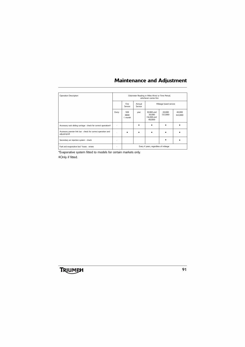
Maintenance and Adjustment
91
*Evaporative system fitted to models for certain markets only.
‡Only if fitted.
Accessory rack sliding carriage - check for correct operation‡ - • • • •
Accessory pannier link bar - check for correct operation and adjustment‡
- • • • • •
Secondary air injection system - check - • •
Fuel and evaporative loss* hoses - renew - Every 4 years, regardless of mileage
Operation Description Odometer Reading in Miles (Kms) or Time Period,whichever comes first
First Service
Annual Service
Mileage based service
Every 500(800)
1 month
year 10,000 and 30,000
(16,000 and 48,000)
20,000(32,000)
40,000(64,000)

92
Maintenance and Adjustment
Engine Oil
In order for the engine, transmission, andclutch to function correctly, maintain theengine oil at the correct level, and change theoil and oil filter in accordance with scheduledmaintenance requirements.
Oil Level Inspection
1. Filler plug2. Sight glass3. Oil level (correct level shown)4. Crankcase oil level lines
WarningMotorcycle operation with insufficient,deteriorated, or contaminated engine oilwill cause accelerated engine wear andmay result in engine or transmissionseizure. Seizure of the engine ortransmission may lead to sudden loss ofcontrol and an accident.
cbnz
WarningNever start the engine or run the engine ina confined area. Exhaust fumes arepoisonous and can cause loss ofconsciousness and death within a shortperiod of time. Always operate yourmotorcycle in the open-air or in an areawith adequate ventilation.
CautionRunning the engine with insufficient oil willcause engine damage. If the low oilpressure indicator remains on, stop theengine immediately and investigate thecause.
2
4 31
chgz
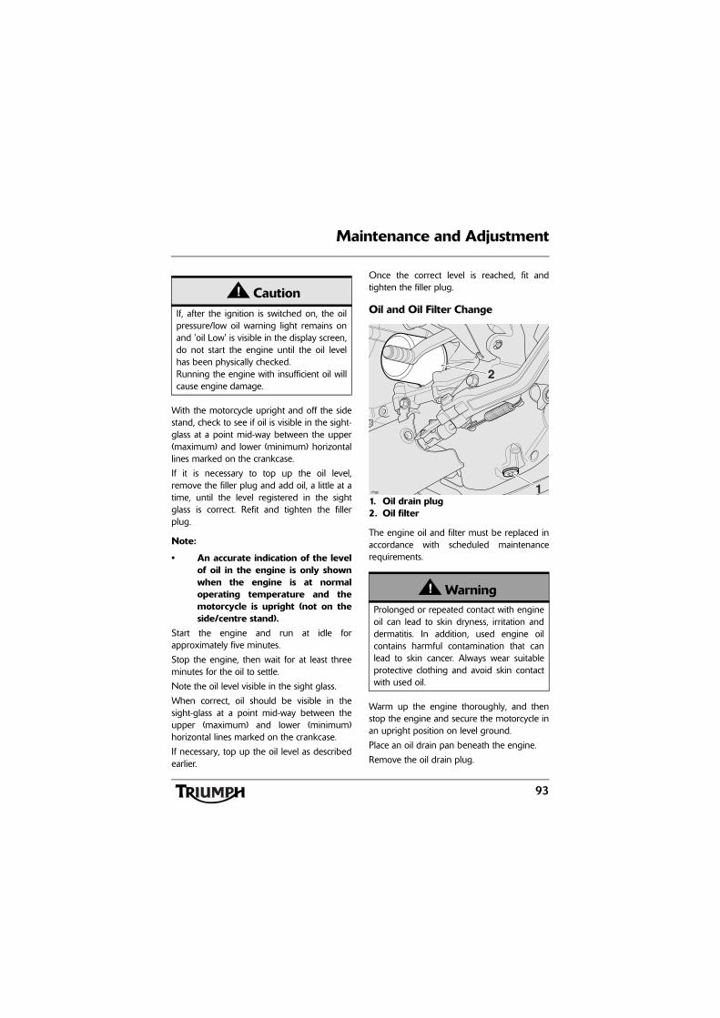
93
Maintenance and Adjustment
With the motorcycle upright and off the sidestand, check to see if oil is visible in the sight-glass at a point mid-way between the upper(maximum) and lower (minimum) horizontallines marked on the crankcase.
If it is necessary to top up the oil level,remove the filler plug and add oil, a little at atime, until the level registered in the sightglass is correct. Refit and tighten the fillerplug.
Note:
• An accurate indication of the levelof oil in the engine is only shownwhen the engine is at normaloperating temperature and themotorcycle is upright (not on theside/centre stand).
Start the engine and run at idle forapproximately five minutes.
Stop the engine, then wait for at least threeminutes for the oil to settle.
Note the oil level visible in the sight glass.
When correct, oil should be visible in thesight-glass at a point mid-way between theupper (maximum) and lower (minimum)horizontal lines marked on the crankcase.
If necessary, top up the oil level as describedearlier.
Once the correct level is reached, fit andtighten the filler plug.
Oil and Oil Filter Change
1. Oil drain plug2. Oil filter
The engine oil and filter must be replaced inaccordance with scheduled maintenancerequirements.
Warm up the engine thoroughly, and thenstop the engine and secure the motorcycle inan upright position on level ground.
Place an oil drain pan beneath the engine.
Remove the oil drain plug.
CautionIf, after the ignition is switched on, the oilpressure/low oil warning light remains onand 'oil Low' is visible in the display screen,do not start the engine until the oil levelhas been physically checked.Running the engine with insufficient oil willcause engine damage.
WarningProlonged or repeated contact with engineoil can lead to skin dryness, irritation anddermatitis. In addition, used engine oilcontains harmful contamination that canlead to skin cancer. Always wear suitableprotective clothing and avoid skin contactwith used oil.
2
1chgy

94
Maintenance and Adjustment
Unscrew and remove the oil filter usingTriumph service tool T3880313. Dispose ofthe old filter in an environmentally friendlyway.
Apply a thin smear of clean engine oil to thesealing ring of the new oil filter. Fit the oilfilter and tighten to 10 Nm.
After the oil has completely drained out, fit anew sealing washer to the drain plug. Fit andtighten the plug to 25 Nm.
Fill the engine with a 10W/40 or 10W/50semi or fully synthetic motorcycle engine oilthat meets specification API SH (or higher)and JASO MA, such as Castrol Power 1Racing 4T 10W-40 (fully synthetic) engine oil,sold as Castrol Power RS Racing 4T 10W-40(fully synthetic) in some countries.
Start the engine and allow it to idle for aminimum of 30 seconds.
Ensure that the low oil pressure warning lightremains off after starting and the 'oil Lo' or'oil Pr' is not visible in the instrument's displayscreen.
Stop the engine and re-check the oil level.Adjust if necessary.
Disposal of Used Engine Oil and Oil FiltersTo protect the environment, do not pour oilon the ground, down sewers or drains, orinto watercourses. Do not place used oil filtersin with general waste. If in doubt, contactyour local authority.
WarningThe oil may be hot to the touch. Avoidcontact with the hot oil by wearing suitableprotective clothing, gloves, eye protection,etc. Contact with hot oil may cause the skinto be scalded or burned.
CautionRaising the engine speed above idle beforethe oil reaches all parts of the engine cancause engine damage or seizure. Onlyraise engine speed after running theengine for 30 seconds to allow the oil tocirculate fully.
CautionIf the engine oil pressure is too low, the lowoil pressure warning light will illuminate. Ifthis light stays on when the engine isrunning, stop the engine immediately andinvestigate the cause. Running the enginewith low oil pressure will cause enginedamage.

95
Maintenance and Adjustment
Oil Specification and GradeTriumph high performance fuel injectedengines are designed to use 10W/40 or15W/50 semi or fully synthetic motorcycleengine oil that meets specification API SH (orhigher) and JASO MA, such asCastrol Power 1 Racing 4T 10W-40 (fullysynthetic) engine oil, sold as Castrol Power RSRacing 4T 10W-40 (fully synthetic) in somecountries.
Do not add any chemical additives to theengine oil. The engine oil also lubricates theclutch and any additives could cause theclutch to slip.
Do not use mineral, vegetable, non-detergentoil, castor based oils or any oil notconforming to the required specification. Theuse of these oils may cause instant, severeengine damage.
Cooling System
To ensure efficientengine cooling, checkthe coolant level eachday before riding themotorcycle, and top upthe coolant if the levelis low.
Note:
• A year-round, Hybrid Organic AcidTechnology (known as Hybrid OATor HOAT) coolant is installed in thecooling system when themotorcycle leaves the factory. It iscoloured green, contains a 50%solution of ethylene glycol basedantifreeze, and has a freezingpoint of -35°C (-31°F).
Corrosion InhibitorsTo protect the cooling system from corrosion,the use of corrosion inhibitor chemicals in thecoolant is essential.
If coolant containing a corrosion inhibitor isnot used, the cooling system will accumulaterust and scale in the water jacket and radiator.This will block the coolant passages, andconsiderably reduce the efficiency of thecooling system.
cbob

96
Maintenance and Adjustment
Note:
• HD4X Hybrid OAT coolant, assupplied by Triumph, is pre-mixedand does not need to be dilutedprior to filling or topping up thecooling system.
Coolant Level Inspection
Note:
• The coolant level should bechecked when the engine is cold(at room or ambient temperature).
1. Expansion tank2. MAX mark3. MIN mark
Position the motorcycle on level ground andin an upright position. The expansion tankcan be viewed from the left hand side of themotorcycle.
Check the coolant level in the expansiontank. The coolant level must be between theMAX and MIN marks. If the coolant is belowthe minimum level, the coolant level must beadjusted.
WarningHD4X Hybrid OAT coolant containscorrosion inhibitors and anti-freeze suitablefor aluminium engines and radiators.Always use the coolant in accordance withthe instructions of the manufacturer.
Coolant that contains anti-freeze andcorrosion inhibitors contains toxicchemicals that are harmful to the humanbody. Never swallow anti-freeze or any ofthe motorcycle coolant.
3
1
2
chgw

97
Maintenance and Adjustment
Coolant Level Adjustment
1. Expansion tank2. Expansion tank cap
Allow the engine to cool.
The expansion tank cap can be removedfrom the left hand side of the motorcycle.
Remove the cap from the expansion tankand add coolant mixture through the filleropening until the level reaches the MAXmark. Refit the cap.
Note:
• If the coolant level is beingchecked because the coolant hasoverheated, also check the level inthe radiator and top up ifnecessary.
• In an emergency, distilled watercan be added to the coolingsystem. However, the coolantmust then be drained andreplenished with HD4XHybrid OAT coolant as soon aspossible.
Coolant ChangeHave the coolant changed by an authorisedTriumph dealer in accordance with scheduledmaintenance requirements.
WarningDo not remove the radiator pressure capwhen the engine is hot. When the engineis hot, the coolant inside the radiator will behot and also under pressure. Contact withthis hot, pressurised coolant will causescalds and skin damage.
1
2
chgw_1
CautionIf hard water is used in the cooling system,it will cause scale accumulation in theengine and radiator and considerablyreduce the efficiency of the cooling system.Reduced cooling system efficiency maycause the engine to overheat and suffersevere damage.
98
Maintenance and Adjustment
Radiator and HosesCheck the radiator hoses for cracks ordeterioration, and hose clips for tightness inaccordance with scheduled maintenancerequirements. Have your authorised Triumphdealer replace any defective items.
Check the radiator grille and fins forobstructions by insects, leaves or mud. Cleanoff any obstructions with a stream oflow-pressure water.
Inspection
Check that the throttle opens smoothly,without undue force and that it closes withoutsticking. Have your authorised Triumphdealer check the throttle system if a problemis detected or any doubt exists.
Check that there is 1 - 2 mm of throttle gripfree play when lightly turning the throttle gripback and forth.
If there is an incorrect amount of free play,Triumph recommends that you have yourauthorised Triumph dealer investigate.
WarningThe fan operates automatically when theengine is running. Always keep hands andclothing away from the fan as contact withthe rotating fan can cause injury.
CautionUsing high-pressure water sprays, such asfrom a car wash facility or householdpressure washer, can damage the radiatorfins, cause leaks and impair the radiator'sefficiency.
Do not obstruct or deflect airflow throughthe radiator by installing unauthorisedaccessories, either in front of the radiator orbehind the cooling fan. Interference withthe radiator airflow can cause overheating,potentially resulting in engine damage.
WarningAlways be alert for changes in the 'feel' ofthe throttle control and have the throttlesystem checked by an authorised Triumphdealer if any changes are detected.Changes can be due to wear in themechanism, which could lead to a stickingthrottle control.
A sticking or stuck throttle control will leadto loss of motorcycle control and anaccident.
WarningUse of the motorcycle with a sticking ordamaged throttle control will interfere withthe throttle function resulting in loss ofmotorcycle control and an accident.
To avoid continued use of a sticking ordamaged throttle control, always have itchecked by your authorised Triumphdealer.

99
Maintenance and Adjustment
ClutchThe motorcycle is equipped with ahydraulically operated clutch that does notrequire adjustment.
Clutch Fluid Level Inspection and Adjustment
Inspect the level of brake and clutch fluid inthe reservoir and change the fluid inaccordance with the scheduled maintenancerequirements. Use only DOT 4 fluid asrecommended in the specification section.The brake and clutch fluid must also bechanged if it becomes, or is suspected ofhaving become contaminated with moistureor any other contaminants.
The brake and clutch fluid in the reservoirmust be kept between the upper and lowerlevel lines (reservoir held horizontal).
Release the fixings securing the clutchreservoir cover, then remove the cover notingthe position of the diaphragm seal.
Fill the reservoir to the upper level line usingnew DOT 4 fluid from a sealed container.
Refit the reservoir cover ensuring that thediaphragm seal is correctly fitted. Tighten thefixings to 1 Nm.
1. Fixings2. Cover3. Diaphragm seal4. Upper level line5. Lower level line
WarningUse only DOT 4 specification brake andclutch fluid as listed in the specificationsection of this handbook. The use of brakeand clutch fluids other than those DOT 4fluids listed in the specification section mayreduce the efficiency of the clutch systemleading to an accident.
Failure to change the brake and clutch fluidat the interval specified in the scheduledmaintenance chart may reduce clutchefficiency resulting in an accident.
5
1 1
23
4
chgv

100
Maintenance and Adjustment
Final Drive UnitOther than checking the final drive oil level,the unit contains no user serviceable parts. Ifa fault occurs with the final drive unit, yourTriumph dealer must replace the completeassembly.
Check the final drive unit for oil leaks inaccordance with the scheduled maintenancechart.
Final Drive Oil Level Adjustment
1. Filler level plugTo check the oil level in the final drive unit,remove the filler level plug. Fill with 75W/90fully synthetic hypoid oil that meetsspecification API Service Level GL5, such asCastrol SAF-XO fully synthetic hypoid oil,until the level of oil inside the unit is level withthe bottom of the filler. Refit the plug andtighten to 25 Nm.
1
chew
WarningUnder no circumstances should the finaldrive unit be disassembled. Failure toobserve the above warning could lead to amalfunction of the final drive unit causinglock-up of the rear wheel leading to loss ofmotorcycle control and an accident.

101
Maintenance and Adjustment
Brakes
Brake Wear Inspection
1. Brake pads2. Minimum thickness line
Brake pads must be inspected in accordancewith scheduled requirements and replaced ifworn to, or beyond the minimum servicethickness.
If the lining thickness of any pad (front or rearbrakes) is less than 1.5 mm (0.06 in), that is, ifthe pad has worn down to the bottom of thegrooves, replace all the pads on the wheel.
Breaking-in New Brake Pads and DiscsAfter replacement brake discs and/or padshave been fitted to the motorcycle, werecommend a period of careful breaking-inthat will optimise the performance andlongevity of the discs and pads. Therecommended distance for breaking-in newpads and discs is 200 miles (300 km).
After fitting new brake discs and/or padsavoid extreme braking, ride with caution andallow for greater braking distances during thebreaking-in period.
cbmz
1
2
WarningBrake pads must always be replaced as awheel set. At the front, where two calipersare fitted on the same wheel, replace allthe brake pads in both calipers.
Replacing individual pads will reducebraking efficiency and may cause anaccident.
After replacement brake pads have beenfitted, ride with extreme caution until thenew pads have 'broken in'.
WarningBrake pad wear will be increased if themotorcycle is used frequently off-road.Always inspect the brake pads morefrequently if the motorcycle is usedoff-road, and replace the brake padsbefore they become worn to, or beyondthe minimum service thickness. Riding with worn brake pads may reducebraking efficiency, leading to loss ofmotorcycle control and an accident.

102
Maintenance and Adjustment
Brake Pad Wear CompensationDisc and brake pad wear is automaticallycompensated for and has no effect on thebrake lever or pedal action. There are noparts that require adjustment on the frontand rear brakes.
Disc Brake FluidInspect the level of brake fluid in bothreservoirs and change the brake fluid inaccordance with scheduled maintenancerequirements. Use only DOT 4 fluid asrecommended in the Specification section.The brake fluid must also be changed if itbecomes, or is suspected of having becomecontaminated with moisture or any othercontaminants.
WarningIf the brake lever or pedal feels soft when itis applied, or if the lever/pedal travelbecomes excessive, there may be air in thebrake pipes and hoses or the brakes maybe defective.
It is dangerous to operate the motorcycleunder such conditions and your authorisedTriumph dealer must rectify the faultbefore riding.
Riding with defective brakes may lead toloss of motorcycle control and an accident.
WarningBrake fluid is hygroscopic which means itwill absorb moisture from the air.
Any absorbed moisture will greatly reducethe boiling point of the brake fluid causinga reduction in braking efficiency.
Because of this, always replace brake fluidin accordance with scheduled maintenancerequirements.
Always use new brake fluid from a sealedcontainer and never use fluid from anunsealed container or from one which hasbeen previously opened.
Do not mix different brands or grades ofbrake fluid.
Check for fluid leakage around brakefittings, seals and joints and also check thebrake hoses for splits, deterioration anddamage.
Always rectify any faults before riding.
Failure to observe and act upon any ofthese items may cause a dangerous ridingcondition leading to loss of control and anaccident.
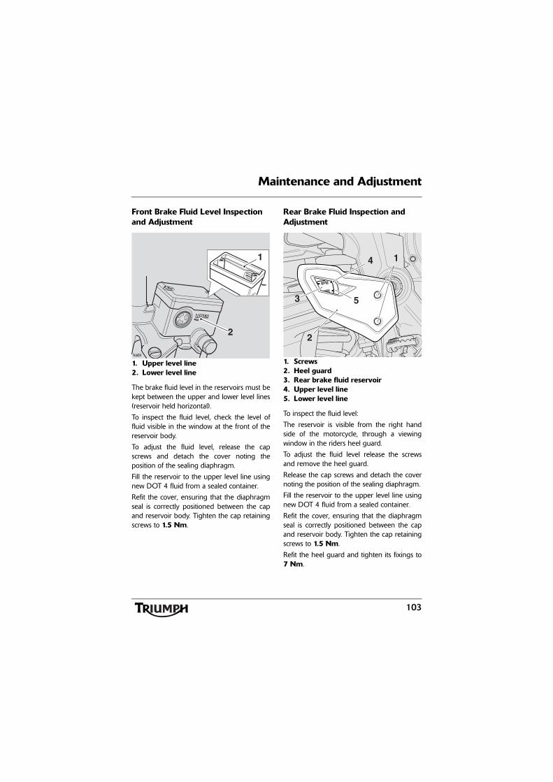
103
Maintenance and Adjustment
Front Brake Fluid Level Inspection and Adjustment
1. Upper level line2. Lower level line
The brake fluid level in the reservoirs must bekept between the upper and lower level lines(reservoir held horizontal).
To inspect the fluid level, check the level offluid visible in the window at the front of thereservoir body.
To adjust the fluid level, release the capscrews and detach the cover noting theposition of the sealing diaphragm.
Fill the reservoir to the upper level line usingnew DOT 4 fluid from a sealed container.
Refit the cover, ensuring that the diaphragmseal is correctly positioned between the capand reservoir body. Tighten the cap retainingscrews to 1.5 Nm.
Rear Brake Fluid Inspection and Adjustment
1. Screws2. Heel guard3. Rear brake fluid reservoir4. Upper level line5. Lower level line
To inspect the fluid level:
The reservoir is visible from the right handside of the motorcycle, through a viewingwindow in the riders heel guard.
To adjust the fluid level release the screwsand remove the heel guard.
Release the cap screws and detach the covernoting the position of the sealing diaphragm.
Fill the reservoir to the upper level line usingnew DOT 4 fluid from a sealed container.
Refit the cover, ensuring that the diaphragmseal is correctly positioned between the capand reservoir body. Tighten the cap retainingscrews to 1.5 Nm.
Refit the heel guard and tighten its fixings to7 Nm.
2
1
3 5
4
h
2
1

104
Maintenance and Adjustment
Brake Light SwitchesThe brake light is activated independently byeither the front or rear brake. If, with theignition in the ON position, the brake lightdoes not work when the front brake lever ispulled or the rear brake pedal is pressed,have your authorised Triumph dealerinvestigate and rectify the fault.
Steering/Wheel Bearings
Steering InspectionLubricate and inspect the condition of thesteering (headstock) bearings in accordancewith scheduled maintenance requirements.
Note:
• Always inspect the wheel bearingsat the same time as the steeringbearings.
WarningIf there has been an appreciable drop inthe level of the fluid in either fluidreservoir, consult your authorised Triumphdealer for advice before riding. Riding withdepleted brake fluid levels, or with a brakefluid leak is dangerous and will causereduced brake performance potentiallyleading to loss of motorcycle control andan accident.
WarningRiding the motorcycle with defective brakelights is illegal and dangerous.
An accident causing injury to the rider andother road users may result from use of amotorcycle with defective brake lights.
CautionTo prevent risk of injury from themotorcycle falling during the inspection,ensure that the motorcycle is stabilised andsecured on a suitable support. Do notexert extreme force against each wheel orrock each wheel vigorously as this maycause the motorcycle to become unstableand cause injury by falling from its support.
Ensure that the position of the supportblock will not cause damage to the sump.

105
Maintenance and Adjustment
Inspecting the Steering (Headstock) Bearings for Free Play
Inspecting the Steering for Free Play
InspectionPosition the motorcycle on level ground, in anupright position.
Raise the front wheel above the ground andsupport the motorcycle.
Standing at the front of the motorcycle, holdthe lower end of the front forks and try tomove them forward and backward.
If any free play can be detected in thesteering (headstock) bearings, ask yourauthorised Triumph dealer to inspect andrectify any faults before riding.
Remove the support and place themotorcycle on the side stand.
Wheel Bearings InspectionIf the wheel bearings in the front or rearwheel allow play in the wheel hub, are noisy,or if the wheel does not turn smoothly, haveyour authorised Triumph dealer inspect thewheel bearings.
The wheel bearings must be inspected at theintervals specified in the scheduledmaintenance chart.
Position the motorcycle on level ground, in anupright position.
Raise the front wheel above the ground andsupport the motorcycle.
Standing at the side of the motorcycle, gentlyrock the top of the front wheel from side toside.
If any free play can be detected, ask yourauthorised Triumph dealer to inspect andrectify any faults before riding.
Reposition the lifting device and repeat theprocedure for the rear wheel.
Remove the support and place themotorcycle on the side stand.Warning
Riding the motorcycle with incorrectlyadjusted or defective steering (headstock)bearings is dangerous and may cause lossof motorcycle control and an accident.
WarningOperation with worn or damaged front orrear wheel bearings is dangerous and maycause impaired handling and instabilityleading to an accident. If in doubt, have themotorcycle inspected by an authorisedTriumph dealer before riding.

106
Maintenance and Adjustment
Front Suspension
Front Fork InspectionExamine each fork for any sign of damage,scratching of the slider surface, or for oilleaks.
If any damage or leakage is found, consult anauthorised Triumph dealer.
To check that the forks operate smoothly:
• Position the motorcycle on levelground.
• While holding the handlebars andapplying the front brake, pump theforks up and down several times.
• If roughness or excessive stiffness isdetected, consult your authorisedTriumph dealer.
Front Suspension SettingsThe front forks have spring pre-loadadjustment only.
Spring Pre-Load Adjustment
1. Spring pre-load adjusterThe spring pre-load adjusters are located atthe top of each fork.
To change the spring pre-load, rotate theadjuster clockwise to increase pre-load, oranti-clockwise to decrease pre-load. Alwayscount the number of anti-clockwise turnsfrom the fully clockwise position and set bothforks to the same setting.
Note:
• The motorcycle is delivered fromthe factory with the springpre-load set at 8 anti-clockwiseturns from the fully clockwiseposition.
WarningRiding the motorcycle with defective ordamaged suspension is dangerous andmay lead to loss of control and an accident.
WarningNever attempt to dismantle any part of thesuspension units, as all units containpressurised oil. Skin and eye damage canresult from contact with the pressurised oil.
1
chey

107
Maintenance and Adjustment
Front Suspension Setting Chart
The standard suspension settings provide acomfortable ride and good handlingcharacteristics for general, solo riding. Thecharts above show suggested settings for thefront suspension.
Rear Suspension
Rear Suspension Setting Chart
The standard suspension settings provide acomfortable ride and good handlingcharacteristics for general, solo riding. Thecharts above show suggested settings for therear suspension.
An increase in spring pre-load requires firmerdamping, a reduction in spring pre-loadrequires softer damping.
The damping must be adjusted to the roadconditions and the spring pre-load.
Loading Spring Pre-Load¹
Solo Riding - Standard 8
Solo Riding - Comfort 8
Rider and Luggage 8
Rider and Passenger 8
Rider, Passenger and Luggage
8
¹ Number of turns anti-clockwise from the fully clockwise position.
Loading Spring Pre-Load²
Rebound damping²
Solo Riding - Standard
20 12
Solo Riding - Comfort
20 18
Rider and luggage 10 12
Rider and Passenger
0 12
Rider, Passenger and Luggage
0 10
² Number of clicks anti-clockwise from the fully clockwise position noting that the first stop (click) is counted as 1.

108
Maintenance and Adjustment
Note:
• The motorcycle is delivered fromthe factory with the rearsuspension set at the standardsettings, as shown in the relevantsuspension chart (see page 107).
• These charts are only a guide.Setting requirements may vary forrider weight and personalpreferences. See the followingpages for information regardingsuspension adjustment.
Rear Suspension AdjustmentThe rear suspension unit on this motorcycle isadjustable for spring pre-load and rebounddamping.
Spring Pre-Load Adjustment
1. Spring pre-load adjusterThe spring pre-load adjuster is situated onthe right hand side of the motorcycle, at thetop of the rear suspension unit.
To adjust the spring pre-load setting rotatethe adjuster clockwise to increase, oranti-clockwise to decrease.
Note:
• The setting is measured as thenumber of adjuster 'clicks'anti-clockwise from the fullyclockwise (hardest) position.
• The motorcycle is delivered fromthe factory with the springpre-load set 20 clicksanti-clockwise from the fullyclockwise position.
WarningEnsure that the correct balance betweenfront and rear suspension is maintained.Suspension imbalance could significantlychange handling characteristics leading toloss of control and an accident. Refer to thefront and rear suspension setting charts forfurther information or consult your dealer.
1
chgr

109
Maintenance and Adjustment
Rebound Damping Adjustment
1. Rebound damping adjusterThe rebound damping adjuster is located atthe bottom of the rear suspension unit and isaccessible from left hand side of themotorcycle.
To adjust the rebound damping setting,rotate the slotted adjuster clockwise toincrease, and anti-clockwise to decrease.
Note:
• The setting is measured as thenumber of adjuster clicksanti-clockwise from the fullyclockwise (hardest) position.
• The motorcycle is delivered fromthe factory with the reboundadjuster set to 12 clicksanti-clockwise from the fullyclockwise position.
1
chgq
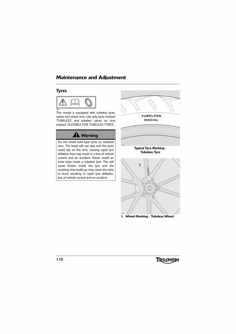
110
Maintenance and Adjustment
Tyres
This model is equipped with tubeless tyres,valves and wheel rims. Use only tyres marked'TUBELESS' and tubeless valves on rimsmarked 'SUITABLE FOR TUBELESS TYRES'.
Typical Tyre Marking - Tubeless Tyre
1. Wheel Marking - Tubeless Wheel
WarningDo not install tube-type tyres on tubelessrims. The bead will not seat and the tyrescould slip on the rims, causing rapid tyredeflation that may result in a loss of vehiclecontrol and an accident. Never install aninner tube inside a tubeless tyre. This willcause friction inside the tyre and theresulting heat build-up may cause the tubeto burst resulting in rapid tyre deflation,loss of vehicle control and an accident.
cboa
cfhb
1
chez

111
Maintenance and Adjustment
Tyre Inflation PressuresCorrect tyre inflation pressures will providemaximum stability, rider comfort and tyre life.Always check tyre pressures before ridingwhen the tyres are cold. Check tyre pressuresdaily and adjust if necessary (see Specificationsection for correct inflation pressures).Alternatively, ask your authorised Triumphdealer to inspect your wheels and tyres.
Tyre Pressure Monitoring System (if fitted)The tyre pressures shown on yourinstruments indicate the actual tyre pressureat the time of selecting the display. This maydiffer from the inflation pressure set when thetyres are cold because tyres become warmerduring riding, causing the air in the tyre toexpand and increase the inflation pressure.The cold inflation pressures specified byTriumph take account of this.
Owners must only adjust tyre pressures whenthe tyres are cold using an accurate pressuregauge, and must not use the tyre pressuredisplay on the instruments.
WarningIncorrect tyre inflation will cause abnormaltread wear and instability problems whichmay lead to loss of control and an accident.
Under-inflation may result in the tyreslipping on, or coming off the rim.Over-inflation will cause instability andaccelerated tread wear.
Both conditions are dangerous as they maycause loss of control leading to an accident.
WarningTyre pressures which have been reducedfor off-road riding will impair on-roadstability. Always ensure the tyre pressureare set as described in the Specificationsection for on-road use.
Operation of the motorcycle with incorrecttyre pressures may cause loss ofmotorcycle control leading to an accident.

112
Maintenance and Adjustment
Tyre Wear
As the tyre tread wears down, the tyrebecomes more susceptible to punctures. It isestimated that 90% of all tyre problems occurduring the last 10% of tread life (90% worn).It is therefore not recommended to use tyresuntil they are worn to their minimum.
Minimum Recommended Tread DepthIn accordance with the periodic maintenancechart, measure the depth of the tread with adepth gauge, and replace any tyre that hasworn to, or beyond, the minimum allowabletread depth specified in the table below:
Under 130 km/h (80 mph)
2 mm (0.08 in)
Over 130 km/h (80 mph)
Rear 3 mm (0.12 in) Front 2 mm (0.08 in)
WarningThis motorcycle must not be operatedabove the legal road speed limit except inauthorised closed-course conditions.
cboa
WarningOnly operate this Triumph motorcycle athigh speed in closed-course on-roadcompetition or on closed-course racetracks.High-speed operation should only then beattempted by riders who have beeninstructed in the techniques necessary forhigh-speed riding and are familiar with themotorcycle's characteristics in allconditions. High-speed operation in anyother circumstances is dangerous and willlead to loss of motorcycle control and anaccident.
WarningOperation with excessively worn tyres ishazardous and will adversely affecttraction, stability and handling which maylead to loss of control and an accident.
When tyres become punctured, leakage isoften very slow. Always inspect tyres veryclosely for punctures. Check the tyres forcuts, embedded nails or other sharpobjects. Operation with punctured ordamaged tyres will adversely affect stabilityand handling which may lead to loss ofcontrol or an accident.
Check the rims for dents or deformationand spokes for looseness and damage.Operation with damaged or defectivewheels, spokes or tyres is dangerous andloss of control or an accident could result.
Always consult your authorised Triumphdealer for tyre replacement, or for a safetyinspection of the wheels, spokes and tyres.

113
Maintenance and Adjustment
Tyre ReplacementAll Triumph motorcycles are carefully andextensively tested in a range of ridingconditions to ensure that the most effectivetyre combinations are approved for use onthis model. It is essential that approved tyres,fitted in approved combinations, are usedwhen purchasing replacement tyres. The useof non-approved tyres, or approved tyres innon-approved combinations, may lead tomotorcycle instability and an accident. Onmodels fitted with ABS, different wheelspeeds, caused by non-approved tyres canaffect the function of the ABS computer.See the Specification section for details ofapproved tyre combinations. Always havetyres fitted and balanced by your authorisedTriumph dealer who has the necessarytraining and skills to ensure safe, effectivefitment.
Tyre Pressure Monitoring System(Only on models fitted with TPMS)
CautionAn adhesive label is fitted to the wheel rimto indicate the position of the tyre pressuresensor. Care must be taken when replacingthe tyres to prevent any damage to the tyrepressure sensors. Always have your tyresfitted by your authorised Triumph dealerand inform them that tyre pressure sensorsare fitted to the wheels.
WarningUse of non-recommended tyres can affectwheel speed and cause the Triumphtraction control function not to operate,potentially leading to loss of control and anaccident in conditions where the Triumphtraction control would normally function.
WarningThe ABS computer operates by comparingthe relative speed of the front and rearwheels. Use of non-recommended tyrescan affect wheel speed and cause the ABSfunction not to operate, potentially leadingto loss of control and an accident inconditions where the ABS would normallyfunction.
WarningIf a tyre sustains a puncture, the tyre mustbe replaced. Failure to replace a puncturedtyre, or operation with a repaired tyre canlead to instability, loss of control or anaccident.

114
Maintenance and Adjustment
WarningDo not install tube-type tyres on tubelessrims. The bead will not seat and the tyrescould slip on the rims, causing rapid tyredeflation that may result in a loss of vehiclecontrol and an accident. Never install aninner tube inside a tubeless tyre. This willcause friction inside the tyre and theresulting heat build-up may cause the tubeto burst resulting in rapid tyre deflation,loss of vehicle control and an accident.
WarningIf tyre damage is suspected, such as afterstriking the kerb, ask your authorisedTriumph dealer to inspect the tyre bothinternally and externally. Remember, tyredamage may not always be visible fromthe outside. Operation of the motorcyclewith damaged tyres could lead to loss ofcontrol and an accident.
WarningWhen replacement tyres or inner tubes arerequired, consult your authorised Triumphdealer who will arrange for the tyres andinner tubes to be selected, in a correctcombination, from the approved list andfitted according to the tyre and inner tubemanufacturer's instructions.
When tyres and inner tubes are replaced,allow time for the tyres and inner tubes toseat to the rim (approximately 24 hours).During this seating period, ride cautiouslyas an incorrectly seated tyre or inner tubecould cause instability, loss of motorcyclecontrol and an accident.
Initially, the new tyres and inner tubes willnot produce the same handlingcharacteristics as the worn tyres and innertubes and the rider must allow adequateriding distance (approximately 100 miles)to become accustomed to the newhandling characteristics.
24 hours after fitting, the tyre pressuresmust be checked and adjusted, and thetyres and inner tubes examined for correctseating. Rectification must be carried out asnecessary.
The same checks and adjustments mustalso be carried out when 100 miles havebeen travelled after fitting.
Use of a motorcycle with incorrectly seatedtyres or inner tubes, incorrectly adjustedtyre pressures, or when not accustomed toits handling characteristics may lead to lossof motorcycle control and an accident.

115
Maintenance and Adjustment
BatteryWarning
Tyres that have been used on a rollingroad dynamometer may becomedamaged. In some cases, the damage maynot be visible on the external surface of thetyre. Tyres must be replaced after such useas continued use of a damaged tyre maylead to instability, loss of control and anaccident.
WarningUse of a motorcycle with incorrectly seatedtyres, incorrectly adjusted tyre pressures, orwhen not accustomed to its handlingcharacteristics may lead to loss of controland an accident.
WarningAccurate wheel balance is necessary forsafe, stable handling of the motorcycle. Donot remove or change any wheel balanceweights. Incorrect wheel balance maycause instability leading to loss of controland an accident.
When wheel balancing is required, such asafter tyre replacement, see your authorisedTriumph dealer.
Only use self-adhesive weights. Clip-onweights may damage the wheel and tyreresulting in tyre deflation, loss of controland an accident.
WarningUnder some circumstances, the battery cangive off explosive gases; keep sparks,flames and cigarettes away. Provideadequate ventilation when charging orusing the battery in an enclosed space.
The battery contains sulphuric acid (batteryacid). Contact with skin or eyes may causesevere burns. Wear protective clothing anda face shield.
If battery acid gets on your skin, flush withwater immediately.
If battery acid gets in your eyes, flush withwater for at least 15 minutes and SEEKMEDICAL ATTENTION IMMEDIATELY.
If battery acid is swallowed, drink largequantities of water and SEEK MEDICALATTENTION IMMEDIATELY.
KEEP BATTERY ACID OUT OF THEREACH OF CHILDREN.
WarningThe battery contains harmful materials.Always keep children away from thebattery whether or not it is fitted in themotorcycle.
Do not attach jump leads to the battery,touch the battery cables together orreverse the polarity of the cables as any ofthese actions may cause a spark whichwould ignite battery gases causing a risk ofpersonal injury.

116
Maintenance and Adjustment
Battery Removal
1. Battery2. Negative (black) terminal3. Positive (red) terminal4. Battery strap
Remove the rider's seat.
Remove the battery strap.
Disconnect the battery leads, negative (black)lead first.
Take the battery out of the case.
Battery DisposalShould the battery ever require replacement,the original battery must be handed to arecycling agent who will ensure that thedangerous substances from which the batteryis manufactured do not pollute theenvironment.
Battery MaintenanceClean the battery using a clean, dry cloth. Besure that the cable connections are clean.
The battery is a sealed type and does notrequire any maintenance other than checkingthe Voltage and routine recharging whenrequired, such as during storage.
It is not possible to adjust the battery acidlevel in the battery; the sealing strip must notbe removed.Warning
Ensure that the battery terminals do nottouch the motorcycle frame as this maycause a short circuit or spark, which wouldignite battery gases causing a risk ofpersonal injury.
1
3
2
4
chen
WarningThe battery acid is corrosive and poisonousand will cause damage to unprotectedskin. Never swallow battery acid or allow itto come into contact with the skin. Toprevent injury, always wear eye and skinprotection when handling the battery.

117
Maintenance and Adjustment
Battery Discharge
Under normal conditions, the motorcyclecharging system will keep the battery fullycharged. However, if the motorcycle isunused, the battery will gradually dischargedue to a normal process called self discharge;the clock, engine control module (ECM)memory, high ambient temperatures, or theaddition of electrical security systems or otherelectrical accessories will all increase this rateof battery discharge. Disconnecting thebattery from the motorcycle during storagewill reduce the rate of discharge.
Battery Maintenance During Storage and Infrequent Use of the MotorcycleDuring storage or infrequent use of themotorcycle, inspect the battery Voltageweekly using a digital multimeter. Follow themanufacturer's instructions supplied with themeter.
Should the battery Voltage fall below12.7 Volts, the battery should be charged(see page 118).
Allowing a battery to discharge or leaving itdischarged for even a short period of timecauses sulphation of the lead plates.Sulphation is a normal part of the chemicalreaction inside the battery, however over timethe sulphate can crystallise on the platesmaking recovery difficult or impossible. Thispermanent damage is not covered by themotorcycle warranty, as it is not due to amanufacturing defect.
Keeping the battery fully charged reduces thelikelihood of it freezing in cold conditions.Allowing a battery to freeze will cause seriousinternal damage to the battery.
CautionThe charge level in the battery must bemaintained to maximise battery life.
Failure to maintain the battery charge levelcould cause serious internal damage to thebattery.

118
Maintenance and Adjustment
Battery ChargingFor help with selecting a battery charger,checking the battery Voltage or batterycharging, contact your local authorisedTriumph dealer.
Should the battery Voltage fall below12.7 Volts, the battery should be chargedusing a Triumph approved battery charger.Always follow the instructions supplied withthe battery charger.
For extended periods of storage (beyond twoweeks) the battery should be removed fromthe motorcycle and kept charged using aTriumph approved maintenance charger.
Similarly, should the battery charge fall to alevel where it will not start the motorcycle,remove the battery from the motorcyclebefore charging.
Battery Installation
Place the battery in the battery case.
Reconnect the battery, positive (red) lead first.
Apply a light coat of grease to the terminalsto prevent corrosion.
Cover the positive terminal with theprotective cap.
Refit the battery strap.
Refit the rider's seat.
WarningThe battery gives off explosive gases; keepsparks, flames and cigarettes away. Provideadequate ventilation when charging orusing the battery in an enclosed space.
The battery contains sulphuric acid (batteryacid). Contact with skin or eyes may causesevere burns. Wear protective clothing anda face shield.
If battery acid gets on your skin, flush withwater immediately.
If battery acid gets in your eyes, flush withwater for at least 15 minutes and SEEKMEDICAL ATTENTION IMMEDIATELY.
If battery acid is swallowed, drink largequantities of water and SEEK MEDICALATTENTION IMMEDIATELY.
KEEP BATTERY ACID OUT OF THEREACH OF CHILDREN.
CautionDo not use an automotive quick charger asit may overcharge and may damage thebattery and the alternator.
WarningEnsure that the battery terminals do nottouch the motorcycle frame as this maycause a short circuit or spark, which wouldignite battery gases causing a risk ofpersonal injury.

119
Maintenance and Adjustment
Fuse Boxes
Main Fuse Boxes
1. Left hand fuse box2. Right hand fuse boxThe fuse boxes are located beneath therider’s seat.
To allow access to the fuse boxes, the rider’sseat must be removed.
ABS Fuse Box
1. ABS fuse boxThe ABS fuse box is located beneath therider's seat and behind the right hand mainfuse box.
To allow access to the ABS fuse box therider’s seat must be removed.
2
1
chfa
Front of Motorcycle
WarningAlways replace blown fuses with new onesof the correct rating (as specified on thefuse box cover) and never use a fuse ofhigher rating. Use of an incorrect fusecould lead to an electrical problem,resulting in motorcycle damage, loss ofmotorcycle control and an accident.
1
chgx
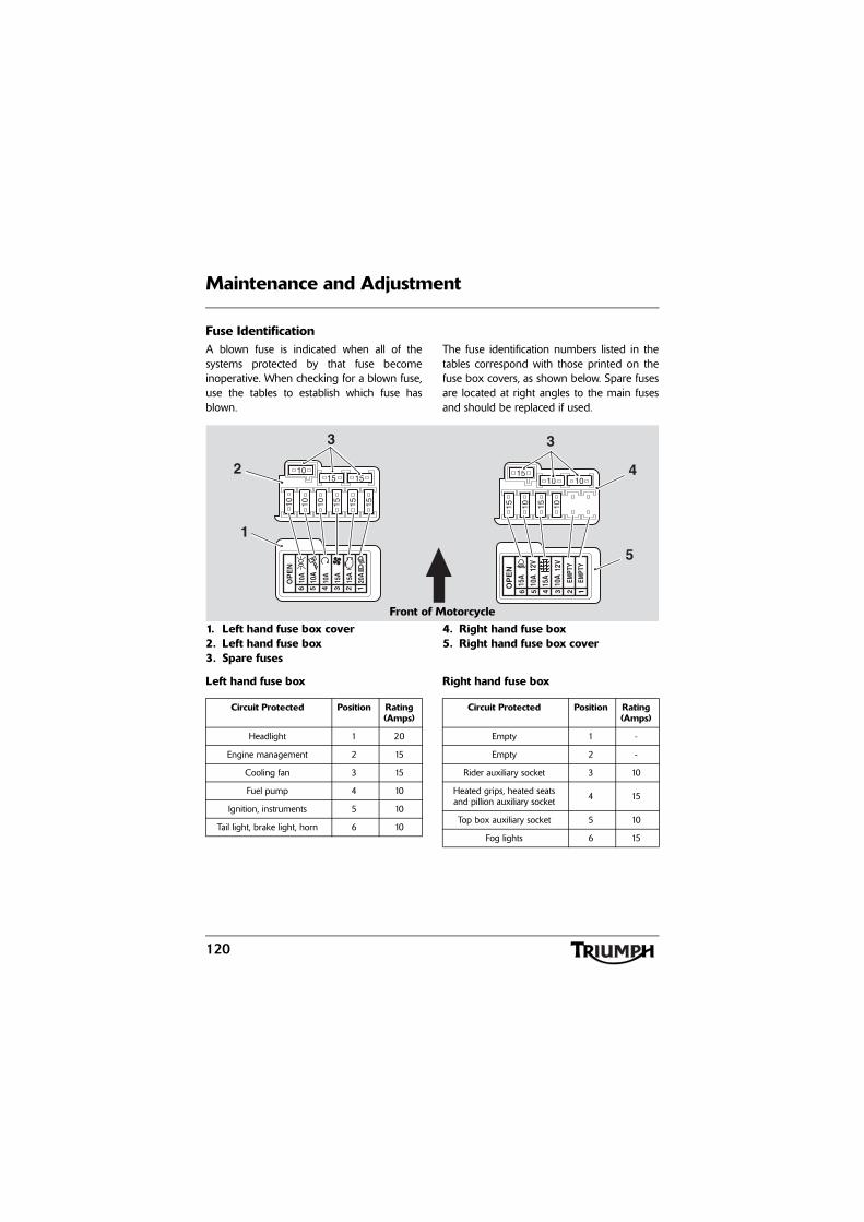
120
Maintenance and Adjustment
Fuse IdentificationA blown fuse is indicated when all of thesystems protected by that fuse becomeinoperative. When checking for a blown fuse,use the tables to establish which fuse hasblown.
The fuse identification numbers listed in thetables correspond with those printed on thefuse box covers, as shown below. Spare fusesare located at right angles to the main fusesand should be replaced if used.
1. Left hand fuse box cover2. Left hand fuse box3. Spare fuses
4. Right hand fuse box5. Right hand fuse box cover
Left hand fuse box Right hand fuse box
1510 10 15
1510
15
15
EMPT
Y
6
OP
EN
15A
5
10A
4
10A
3
20A
2 1
15A
EMPT
Y
10 15 10
1015
10
10
1
OP
EN
2
10A
3
15A
456
15
15A
12V
10A
12V
10A
2
1
4
5
33
Front of Motorcycle
Circuit Protected Position Rating (Amps)
Headlight 1 20
Engine management 2 15
Cooling fan 3 15
Fuel pump 4 10
Ignition, instruments 5 10
Tail light, brake light, horn 6 10
Circuit Protected Position Rating (Amps)
Empty 1 -
Empty 2 -
Rider auxiliary socket 3 10
Heated grips, heated seats and pillion auxiliary socket 4 15
Top box auxiliary socket 5 10
Fog lights 6 15
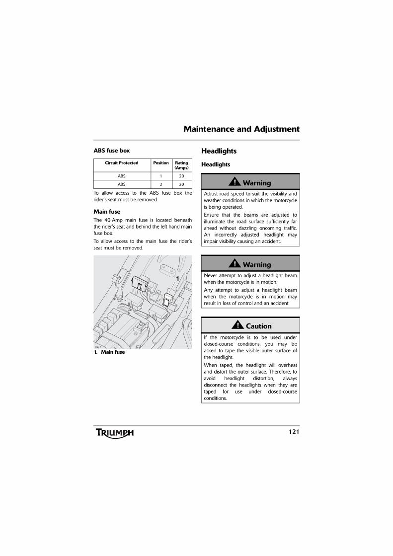
121
Maintenance and Adjustment
ABS fuse box
To allow access to the ABS fuse box therider’s seat must be removed.
Main fuseThe 40 Amp main fuse is located beneaththe rider's seat and behind the left hand mainfuse box.
To allow access to the main fuse the rider’sseat must be removed.
1. Main fuse
Headlights
HeadlightsCircuit Protected Position Rating (Amps)
ABS 1 20
ABS 2 20
1
chgx_1
WarningAdjust road speed to suit the visibility andweather conditions in which the motorcycleis being operated.
Ensure that the beams are adjusted toilluminate the road surface sufficiently farahead without dazzling oncoming traffic.An incorrectly adjusted headlight mayimpair visibility causing an accident.
WarningNever attempt to adjust a headlight beamwhen the motorcycle is in motion.
Any attempt to adjust a headlight beamwhen the motorcycle is in motion mayresult in loss of control and an accident.
CautionIf the motorcycle is to be used underclosed-course conditions, you may beasked to tape the visible outer surface ofthe headlight.
When taped, the headlight will overheatand distort the outer surface. Therefore, toavoid headlight distortion, alwaysdisconnect the headlights when they aretaped for use under closed-courseconditions.
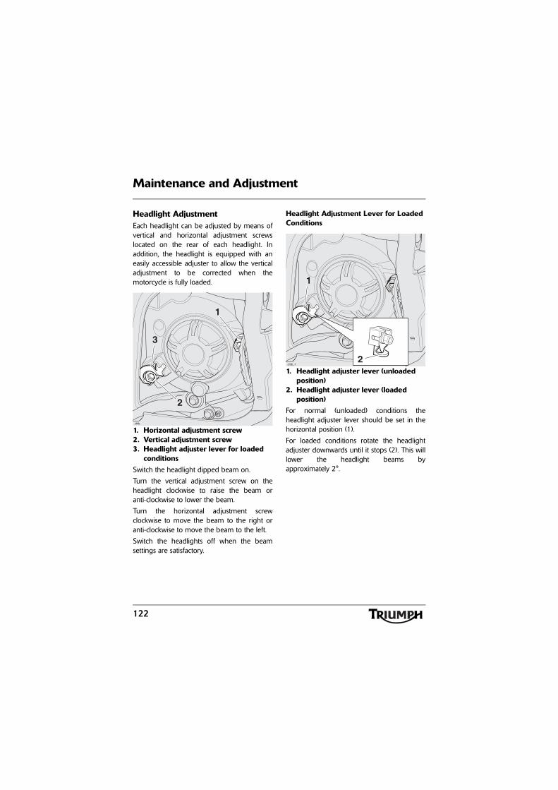
122
Maintenance and Adjustment
Headlight AdjustmentEach headlight can be adjusted by means ofvertical and horizontal adjustment screwslocated on the rear of each headlight. Inaddition, the headlight is equipped with aneasily accessible adjuster to allow the verticaladjustment to be corrected when themotorcycle is fully loaded.
1. Horizontal adjustment screw 2. Vertical adjustment screw3. Headlight adjuster lever for loaded
conditionsSwitch the headlight dipped beam on.
Turn the vertical adjustment screw on theheadlight clockwise to raise the beam oranti-clockwise to lower the beam.
Turn the horizontal adjustment screwclockwise to move the beam to the right oranti-clockwise to move the beam to the left.
Switch the headlights off when the beamsettings are satisfactory.
Headlight Adjustment Lever for Loaded Conditions
1. Headlight adjuster lever (unloaded position)
2. Headlight adjuster lever (loaded position)
For normal (unloaded) conditions theheadlight adjuster lever should be set in thehorizontal position (1).
For loaded conditions rotate the headlightadjuster downwards until it stops (2). This willlower the headlight beams byapproximately 2°.
3
2
1
chfb
1
chfb_12

123
Maintenance and Adjustment
Headlight Bulb Replacement
It is not necessary to remove the headlightwhen bulb replacement becomes necessary.
1. Bulb retainer (right hand shown)2. Bulb retainer hook3. Bulb
To replace a bulb:
Remove the rider's seat.
Disconnect the battery, negative (black) leadfirst.
Remove the bulb cover from the bulb to bereplaced by rotating it anti-clockwise.
Disconnect the multi-plug from the bulb.
Detach the bulb retainer from the hook onthe headlight assembly and rotate it awayfrom the bulb as shown.
Remove the bulb from the bulb retainer.
Installation is the reverse of the removalprocedure.
Position Lamp Bulb Replacement
1. Fixings2. Headlight surround3. Position lamp bulb
The position lamp is fitted to the centre of theheadlight. To replace the bulb, remove thefour fixings and remove the headlightsurround, detach the rubber retainer fromthe headlight and pull out the bulb.
Installation is the reverse of the removalprocedure.
CautionThe use of non-approved headlight bulbsmay result in damage to the headlight lens.
Use a genuine Triumph supplied headlightbulb as specified in the Triumph PartsCatalogue.
Always have replacement headlight bulbsinstalled by an authorised Triumph dealer.
WarningThe bulbs become hot during use. Alwaysallow sufficient time for the bulb to coolbefore handling. Avoid touching the glasspart of the bulb. If the glass is touched orgets dirty, clean with alcohol before reuse.
1
2
cgjn
3
2
3
1
1
chgn

124
Maintenance and Adjustment
Front Fog Lights - If Fitted
Front Fog Light Bulb Replacement
1. Release the fixings and washers thendetach the fog lamp from its shroud.
1. Fixings2. Washers3. Fog lamp4. Shroud
2. Remove the two fixings from the rear ofthe lamp unit.
1. Fog lamp2. Fixings
3. Pull the lens out of the case.
4. Disconnect the bullet connector insidethe lamp unit.
5. Remove the two fixings securing thebulb retainer and remove the bulb.
1. Connector2. Bulb retainer3. Fixings
WarningThe bulbs become hot during use. Alwaysallow sufficient time for the bulb to coolbefore handling. Avoid touching the glasspart of the bulb. If the glass is touched orgets dirty, clean with alcohol before reuse.
CautionDo not allow the fog lamp to hangunsupported from the harness during bulbreplacement. Allowing the fog lamp tohang from the harness will cause damageto the fog lamp.
3
2
14
12
cgrb_1
2
1
3cgsq_1

125
Maintenance and Adjustment
6. Installation is the reverse of the removalprocess.
Rear Light/Licence Plate Light
Rear Light/Licence Plate Light ReplacementThe rear light unit is a sealed, maintenancefree LED unit. The licence plate light isintegral to the rear light unit.
Direction Indicator Lights
Bulb Replacement
1. Indicator lens2. Securing screw
The lens on each indicator light is held inplace by a securing screw located in the lensof the light.
Release the screw and remove the lens togain access to the bulb for replacement.
CautionUse a genuine Triumph supplied bulb asspecified in the Triumph Parts Catalogue.Always have replacement bulbs installedby an authorised Triumph dealer.
2
chgi
1

126
Maintenance and Adjustment
CleaningFrequent, regular cleaning is an essential partof the maintenance of your motorcycle. Ifregularly cleaned, the appearance will bepreserved for many years. Cleaning with coldwater containing an automotive cleaner isessential at all times but particularly so afterexposure to sea breezes, sea water, dusty ormuddy roads and in winter when roads aretreated for ice and snow. Do not usehousehold detergent, as the use of suchproducts will lead to premature corrosion.
Although, under the terms of yourmotorcycle warranty, cover is providedagainst the corrosion of certain items, theowner is expected to observe this reasonableadvice which will safeguard against corrosionand enhance the appearance of themotorcycle.
Preparation for WashingBefore washing, precautions must be takento keep water off the following places.
Rear opening of the exhausts: Cover with aplastic bag secured with rubber bands.
Clutch and brake levers, switch housings onthe handlebar: Cover with plastic bags.
Ignition switch and steering lock: Cover thekeyhole with tape.
Remove any items of jewellery such as rings,watches, zips or belt buckles, which mayscratch or otherwise damage painted orpolished surfaces.
Use separate cleaning sponges or cleaningcloths for washing painted/polished surfacesand chassis areas. Chassis areas (such aswheels and under mudguards) will beexposed to more abrasive road grime anddust, which may then scratch painted orpolished surfaces, if the same sponge orcleaning cloths are used.

127
Maintenance and Adjustment
Where to be CarefulAvoid spraying water with any great forcenear the following places:
• Instruments;
• Brake cylinders and brake calipers;
• Under the fuel tank;
• Headstock bearings.
Note:
• Use of soaps that are highlyalkaline will leave a residue onpainted surfaces, and may alsocause water spotting. Always use alow alkaline soap to aid thecleaning process.
After WashingRemove the plastic bags and tape, and clearthe air intakes.
Lubricate the pivots, bolts and nuts.
Test the brakes before motorcycle operation.
Start the engine and run it for 5 minutes.Ensure adequate ventilation for the exhaustfumes.
Use a dry cloth to absorb water residue. Donot allow water to stand on the machine asthis will lead to corrosion.
Seat Care
To help maintain its appearance, clean theseat using a sponge or cleaning cloth withsoap and water.
CautionAny water sprayed around the air intakeduct could enter the airbox and engine,causing damage to both items.
CautionUse of high-pressure spray washers is notrecommended. When using pressurewashers, water may be forced intobearings and other components causingpremature wear from corrosion and loss oflubrication.
WarningNever wax or lubricate the brake discs.Loss of braking power and an accidentcould result. Clean the disc with aproprietary brand of oil-free brake disccleaner.
CautionUse of chemicals or high-pressure spraywashers is not recommended for cleaningthe seat. Using chemicals or pressurewashers may damage the seat cover.

128
Maintenance and Adjustment
Unpainted Aluminium ItemsItems such as brake and clutch levers, wheels,engine covers, top and bottom yokes onsome models must be correctly cleaned topreserve their appearance. Please contactyour dealer if you are unsure whichcomponents on your motorcycle areunpainted aluminium parts.
Use a proprietary brand of aluminiumcleaner.
Clean aluminium items regularly, in particularafter use in inclement weather, where thecomponents must be hand washed and driedeach time the machine is used.
Warranty claims due to inadequatemaintenance will not be allowed.
Windscreen Cleaning
Clean the windscreen with a solution of mildsoap or detergent and lukewarm water. Aftercleaning, rinse well and then dry with a soft,lint free cloth.
If the transparency of the windscreen isreduced by scratches or oxidation whichcannot be removed, the windscreen must bereplaced.
CautionProducts such as window cleaning fluids,insect remover, rain repellent, scouringcompounds, petrol or strong solvents suchas alcohol, acetone, carbon tetrachloride,etc. will damage the windscreen. Neverallow these products to contact the screen.
WarningNever attempt to clean the windscreenwhile the motorcycle is in motion asreleasing the handlebars may cause loss ofvehicle control and an accident.
Operation of the motorcycle with adamaged or scratched windscreen willreduce the rider's forward vision. Any suchreduction in forward vision is dangerousand may lead to an accident causing injuryor death.
CautionCorrosive chemicals such as battery acidwill damage the windscreen. Never allowcorrosive chemicals to contact thewindscreen.
129
Maintenance and Adjustment
Cleaning of the Exhaust SystemAll parts of the exhaust system of yourmotorcycle must be cleaned regularly toavoid a deterioration of its appearance.
Note:
• The exhaust system must be coolbefore washing to prevent waterspotting.
WashingPrepare a mixture of cold water and mildautomotive cleaner. Do not use a highlyalkaline soap as commonly found atcommercial car washes because it leaves aresidue.
Wash the exhaust system with a soft cloth. Donot use an abrasive scouring pad or steelwool. They will damage the finish.
Rinse the exhaust system thoroughly.
Ensure no soap or water enters the mufflers.
DryingDry the exhaust system as far as possible witha soft cloth. Do not run the engine to dry thesystem or spotting will occur.
ProtectingWhen the exhaust system is dry, rub'Motorex 645 Clean and Protect' into thesurface.
It is recommended that regular protection beapplied to the system as this will both protectand enhance the system's appearance.
CautionThe use of abrasive cleaners and polisheswill damage the system and must not beused.

Maintenance and Adjustment
130
This page intentionally left blank

131
Storage
STORAGE
Preparation for StorageClean and dry the entire vehicle thoroughly.
Fill the fuel tank with the correct grade ofunleaded fuel and add a fuel stabiliser (ifavailable), following the fuel stabilisermanufacturer's instructions.
Remove the spark plug from each cylinderand put several drops (5 ml) of engine oil intoeach cylinder. Cover the spark plug holeswith a piece of cloth or rag. With the enginestop switch in the RUN position, push thestarter button for a few seconds to coat thecylinder walls with oil. Install the spark plugs,tightening to 12 Nm.
Change the engine oil and filter (seepage 93).
Check and if necessary correct the tyrepressures (see page 137).
Set the motorcycle on a stand so that bothwheels are raised off the ground. (If thiscannot be done, put boards under the frontand rear wheels to keep dampness awayfrom the tyres.)
Spray rust inhibiting oil (there are a host ofproducts on the market and your dealer willbe able to offer you local advice) on allunpainted metal surfaces to prevent rusting.Prevent oil from getting on rubber parts,brake discs or in the brake calipers.
Make sure the cooling system is filled with a50% mixture of coolant (noting thatHD4X Hybrid OAT coolant, as supplied byTriumph, is pre-mixed and requires nodilution) and distilled water solution (seepage 95).
Remove the battery, and store it where it willnot be exposed to direct sunlight, moisture,or freezing temperatures. During storage itshould be given a slow charge (one ampereor less) about once every two weeks (seepage 115).
Store the motorcycle in a cool, dry area, awayfrom sunlight, and with a minimum dailytemperature variation.
Put a suitable porous cover over themotorcycle to keep dust and dirt fromcollecting on it. Avoid using plastic or similarnon-breathable, coated materials that restrictair flow and allow heat and moisture toaccumulate.
WarningPetrol is extremely flammable and can beexplosive under certain conditions. Turnthe ignition switch off. Do not smoke.Make sure the area is well ventilated andfree from any source of flame or sparks;this includes any appliance with a pilotlight.

132
Storage
Preparation after StorageInstall the battery (if removed) (see page 118).
If the motorcycle has been stored for morethan four months, change the engine oil (seepage 93).
Check all the points listed in the Daily SafetyChecks section.
Before starting the engine, remove the sparkplugs from each cylinder.
Put the side stand down.
Crank the engine on the starter motor severaltimes until the oil pressure light goes out.
Replace the spark plugs, tightening to12 Nm, and start the engine.
Check and if necessary correct the tyrepressures (see page 137).
Clean the entire vehicle thoroughly.
Check the brakes for correct operation.
Test ride the motorcycle at low speeds.

Specifications
133
SPECIFICATIONS
Dimensions
Overall Length . . . . . . . . . . . . . . . . . . . . . 2248 mm (88.5 in)
Overall Width . . . . . . . . . . . . . . . . . . . . . . 885 mm (34.8 in)
Overall Height. . . . . . . . . . . . . . . . . . . . . . 1410 mm (55.5 in)
Wheelbase. . . . . . . . . . . . . . . . . . . . . . . . . 1530 mm (60.2 in)
Seat Height . . . . . . . . . . . . . . . . . . . . . . . . 837 mm (32.9 in)
Weights
Wet Weight . . . . . . . . . . . . . . . . . . . . . . . . 259 kg (571 lb)
Maximum Payload . . . . . . . . . . . . . . . . . . 222 kg (489 lb)
Engine
Type . . . . . . . . . . . . . . . . . . . . . . . . . . . . . . In-line 3 cylinder
Displacement. . . . . . . . . . . . . . . . . . . . . . . 1215 cc
Bore x Stroke . . . . . . . . . . . . . . . . . . . . . . 85 x 71.4 mm
Compression Ratio . . . . . . . . . . . . . . . . . . 11:1
Cylinder Numbering. . . . . . . . . . . . . . . . . Left to Right
Cylinder Sequence . . . . . . . . . . . . . . . . . . 1 at left
Firing Order . . . . . . . . . . . . . . . . . . . . . . . 1-2-3
Starting System . . . . . . . . . . . . . . . . . . . . . Electric Starter

Specifications
134
Performance
Maximum Power (95/1/EC) . . . . . . . . . . . 100.74 kW (137 PS/135 bhp) at 9,000 rpm
Maximum Torque . . . . . . . . . . . . . . . . . . . 121 Nm (89 lb-ft) at 6,400 rpm
Lubrication
Lubrication. . . . . . . . . . . . . . . . . . . . . . . . . Pressure Lubrication (wetsump)
Engine Oil Capacities
Dry Fill . . . . . . . . . . . . . . . . . . . . . . . . . . . . 4.5 litres
Oil/Filter Change . . . . . . . . . . . . . . . . . . . 4.0 litres
Oil Change Only. . . . . . . . . . . . . . . . . . . . 3.85 litres
Cooling
Coolant Type . . . . . . . . . . . . . . . . . . . . . . . Triumph HD4X Hybrid OAT coolant
Water/Anti-freeze ratio . . . . . . . . . . . . . . . 50/50 (premixed as supplied by Triumph)
Coolant Capacity . . . . . . . . . . . . . . . . . . . . 2.8 litres
Thermostat Opens (nominal) . . . . . . . . . 88°C (nominal)

Specifications
135
Fuel System
Type . . . . . . . . . . . . . . . . . . . . . . . . . . . . . . Electronic Fuel Injection
Injectors . . . . . . . . . . . . . . . . . . . . . . . . . . . Solenoid Operated
Fuel Pump . . . . . . . . . . . . . . . . . . . . . . . . . Submerged Electric
Fuel Pressure (nominal). . . . . . . . . . . . . . . 3.5 bar
Fuel
Type . . . . . . . . . . . . . . . . . . . . . . . . . . . . . . 91 RON unleaded
Tank Capacity . . . . . . . . . . . . . . . . . . . . . . (motorcycle upright)
20.0 litres
Ignition
Ignition System . . . . . . . . . . . . . . . . . . . . . Digital Inductive
Electronic Rev Limiter (r/min) . . . . . . . . . . 9,500 (r/min)
Spark Plug . . . . . . . . . . . . . . . . . . . . . . . . . NGK CR8EK
Spark Plug Gap. . . . . . . . . . . . . . . . . . . . . 0.7 mm
Gap Tolerance . . . . . . . . . . . . . . . . . . . . . . +0.05/-0.1 mm

Specifications
136
Transmission
Transmission Type . . . . . . . . . . . . . . . . . . . 6 Speed, Constant Mesh
Clutch Type . . . . . . . . . . . . . . . . . . . . . . . . Wet, Multi-Plate
Final Drive Ratio . . . . . . . . . . . . . . . . . . . . 2.557:1
Gear Ratios:
Front Bevel Box . . . . . . . . . . . . . . . . . . . . . 1.042:1 (24/25)
Rear Bevel Box . . . . . . . . . . . . . . . . . . . . . 2.455:1 (11/27)
1st. . . . . . . . . . . . . . . . . . . . . . . . . . . . . . . . 2.846:1 (13/37)
2nd . . . . . . . . . . . . . . . . . . . . . . . . . . . . . . . 2.056:1 (18/37)
3rd . . . . . . . . . . . . . . . . . . . . . . . . . . . . . . . 1.583:1 (24/38)
4th . . . . . . . . . . . . . . . . . . . . . . . . . . . . . . . 1.333:1 (21/28)
5th . . . . . . . . . . . . . . . . . . . . . . . . . . . . . . . 1.138:1 (29/33)
6th . . . . . . . . . . . . . . . . . . . . . . . . . . . . . . . 1.037:1 (27/28)
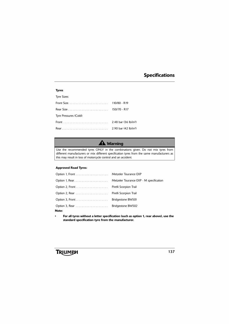
Specifications
137
Tyres
Tyre Sizes:
Front Size. . . . . . . . . . . . . . . . . . . . . . . . . . 110/80 - R19
Rear Size . . . . . . . . . . . . . . . . . . . . . . . . . . 150/70 - R17
Tyre Pressures (Cold):
Front . . . . . . . . . . . . . . . . . . . . . . . . . . . . . 2.48 bar (36 lb/in²)
Rear . . . . . . . . . . . . . . . . . . . . . . . . . . . . . . 2.90 bar (42 lb/in²)
WarningUse the recommended tyres ONLY in the combinations given. Do not mix tyres fromdifferent manufacturers or mix different specification tyres from the same manufacturers asthis may result in loss of motorcycle control and an accident.
Approved Road Tyres:
Option 1, Front . . . . . . . . . . . . . . . . . . . . . Metzeler Tourance EXP
Option 1, Rear . . . . . . . . . . . . . . . . . . . . . . Metzeler Tourance EXP - M specification
Option 2, Front . . . . . . . . . . . . . . . . . . . . . Pirelli Scorpion Trail
Option 2, Rear . . . . . . . . . . . . . . . . . . . . . Pirelli Scorpion Trail
Option 3, Front . . . . . . . . . . . . . . . . . . . . . Bridgestone BW501
Option 3, Rear . . . . . . . . . . . . . . . . . . . . . Bridgestone BW502
Note:
• For all tyres without a letter specification (such as option 1, rear above), use thestandard specification tyre from the manufacturer.

Specifications
138
Electrical Equipment
Battery Type. . . . . . . . . . . . . . . . . . . . . . . . YTX20L-BS
Battery Rating . . . . . . . . . . . . . . . . . . . . . . 12 Volt, 18 Ah
Alternator. . . . . . . . . . . . . . . . . . . . . . . . . . 12 Volt, 70 Amp at 4,000 rpm
Headlight . . . . . . . . . . . . . . . . . . . . . . . . . . 2 x 12 Volt, 55/60 watt, H4 Halogen
Tail/Brake Light . . . . . . . . . . . . . . . . . . . . . LED
Parking light . . . . . . . . . . . . . . . . . . . . . . . 12 Volt, 5 watt
Fog light. . . . . . . . . . . . . . . . . . . . . . . . . . . H3 Halogen12 Volt, 55 watt
Directional Indicator Lights . . . . . . . . . . . . 12 Volt, 10 watt, amber
Frame
Rake. . . . . . . . . . . . . . . . . . . . . . . . . . . . . . 23.9°
Trail . . . . . . . . . . . . . . . . . . . . . . . . . . . . . . 105.5 mm
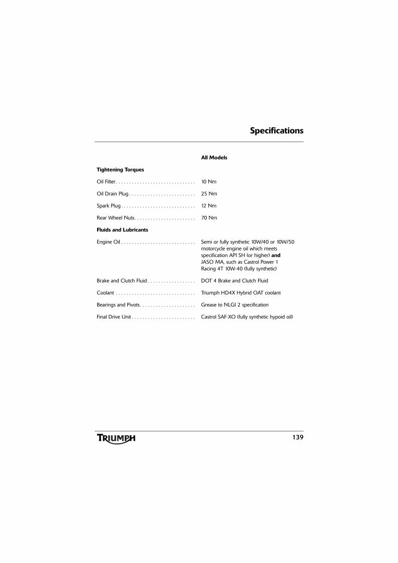
Specifications
139
All Models
Tightening Torques
Oil Filter . . . . . . . . . . . . . . . . . . . . . . . . . . . . . . 10 Nm
Oil Drain Plug . . . . . . . . . . . . . . . . . . . . . . . . . 25 Nm
Spark Plug . . . . . . . . . . . . . . . . . . . . . . . . . . . . 12 Nm
Rear Wheel Nuts. . . . . . . . . . . . . . . . . . . . . . . 70 Nm
Fluids and Lubricants
Engine Oil . . . . . . . . . . . . . . . . . . . . . . . . . . . . Semi or fully synthetic 10W/40 or 10W/50 motorcycle engine oil which meets specification API SH (or higher) and JASO MA, such as Castrol Power 1 Racing 4T 10W-40 (fully synthetic)
Brake and Clutch Fluid . . . . . . . . . . . . . . . . . . DOT 4 Brake and Clutch Fluid
Coolant . . . . . . . . . . . . . . . . . . . . . . . . . . . . . . Triumph HD4X Hybrid OAT coolant
Bearings and Pivots . . . . . . . . . . . . . . . . . . . . . Grease to NLGI 2 specification
Final Drive Unit . . . . . . . . . . . . . . . . . . . . . . . . Castrol SAF-XO (fully synthetic hypoid oil)

Specifications
140
This page intentionally left blank
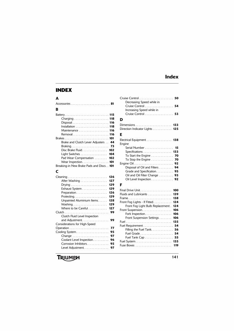
141
Index
INDEX
AAccessories . . . . . . . . . . . . . . . . . . . . . . . . . 81
BBattery . . . . . . . . . . . . . . . . . . . . . . . . . . . . 115
Charging . . . . . . . . . . . . . . . . . . . . . . 118Disposal . . . . . . . . . . . . . . . . . . . . . . . 116Installation . . . . . . . . . . . . . . . . . . . . . 118Maintenance . . . . . . . . . . . . . . . . . . . 116Removal . . . . . . . . . . . . . . . . . . . . . . . 116
Brakes . . . . . . . . . . . . . . . . . . . . . . . . . . . . 101Brake and Clutch Lever Adjusters . . 44Braking. . . . . . . . . . . . . . . . . . . . . . . . 73Disc Brake Fluid . . . . . . . . . . . . . . . . 102Light Switches . . . . . . . . . . . . . . . . . 104Pad Wear Compensation . . . . . . . . 102Wear Inspection. . . . . . . . . . . . . . . . . 101
Breaking-in New Brake Pads and Discs . . 101
CCleaning . . . . . . . . . . . . . . . . . . . . . . . . . 126
After Washing . . . . . . . . . . . . . . . . . 127Drying . . . . . . . . . . . . . . . . . . . . . . . 129Exhaust System . . . . . . . . . . . . . . . . 129Preparation. . . . . . . . . . . . . . . . . . . . 126Protecting. . . . . . . . . . . . . . . . . . . . . 129Unpainted Aluminium Items. . . . . . 128Washing. . . . . . . . . . . . . . . . . . . . . . 129Where to be Careful . . . . . . . . . . . . 127
Clutch . . . . . . . . . . . . . . . . . . . . . . . . . . . . 99Clutch Fluid Level Inspection and Adjustment . . . . . . . . . . . . . . . . . 99
Considerations for High-Speed Operation . . . . . . . . . . . . . . . . . . . . . . . . . 77Cooling System. . . . . . . . . . . . . . . . . . . . . 95
Change . . . . . . . . . . . . . . . . . . . . . . . 97Coolant Level Inspection . . . . . . . . . . 96Corrosion Inhibitors . . . . . . . . . . . . . . 95Level Adjustment. . . . . . . . . . . . . . . . 97
Cruise Control . . . . . . . . . . . . . . . . . . . . . . 50Decreasing Speed while in Cruise Control . . . . . . . . . . . . . . . . . . 54Increasing Speed while in Cruise Control . . . . . . . . . . . . . . . . . . 53
DDimensions . . . . . . . . . . . . . . . . . . . . . . . 133Direction Indicator Lights . . . . . . . . . . . . 125
EElectrical Equipment . . . . . . . . . . . . . . . . 138Engine
Serial Number . . . . . . . . . . . . . . . . . . 15Specifications . . . . . . . . . . . . . . . . . . 133To Start the Engine . . . . . . . . . . . . . . 70To Stop the Engine . . . . . . . . . . . . . . 70
Engine Oil . . . . . . . . . . . . . . . . . . . . . . . . . 92Disposal of Oil and Filters . . . . . . . . . 94Grade and Specification. . . . . . . . . . . 95Oil and Oil Filter Change . . . . . . . . . 93Oil Level Inspection . . . . . . . . . . . . . . 92
FFinal Drive Unit . . . . . . . . . . . . . . . . . . . . 100Fluids and Lubricants . . . . . . . . . . . . . . . 139Frame. . . . . . . . . . . . . . . . . . . . . . . . . . . . 138Front Fog Lights - If Fitted. . . . . . . . . . . . 124
Front Fog Light Bulb Replacement . 124Front Suspension. . . . . . . . . . . . . . . . . . . 106
Fork Inspection. . . . . . . . . . . . . . . . . 106Front Suspension Settings . . . . . . . . 106
Fuel . . . . . . . . . . . . . . . . . . . . . . . . . . . . . 135Fuel Requirement . . . . . . . . . . . . . . . . . . . 54
Filling the Fuel Tank. . . . . . . . . . . . . . 56Fuel Grade . . . . . . . . . . . . . . . . . . . . . 54Fuel Tank Cap . . . . . . . . . . . . . . . . . . 55
Fuel System . . . . . . . . . . . . . . . . . . . . . . . 135Fuse Boxes . . . . . . . . . . . . . . . . . . . . . . . 119

142
Index
GGears
Changing Gears . . . . . . . . . . . . . . . . 72
HHeadlights . . . . . . . . . . . . . . . . . . . . . . . . . 121
Adjustment . . . . . . . . . . . . . . . . . . . 122Bulb Replacement . . . . . . . . . . . . . . 123
IIgnition . . . . . . . . . . . . . . . . . . . . . . . . . . 135
Key . . . . . . . . . . . . . . . . . . . . . . . . . . . 42Switch/Steering Lock . . . . . . . . . . . . . 43
Instrument PanelAuto - Self Cancelling Indicators . . . . 27Change Units. . . . . . . . . . . . . . . . . . . 28Clock Adjustment . . . . . . . . . . . . . . . 29Speedometer . . . . . . . . . . . . . . . . . . . . 21Tachometer . . . . . . . . . . . . . . . . . . . . . 21Trip Meter . . . . . . . . . . . . . . . . . . . . . 22
LLeft Handlebar Switches. . . . . . . . . . . . . . 46
Direction Indicator Switch . . . . . . . . . 47Front Fog Lights Switch, if fitted . . . . 49Headlight Dip Switch. . . . . . . . . . . . . 47Horn Button. . . . . . . . . . . . . . . . . . . . 48Pass Button . . . . . . . . . . . . . . . . . . . . 48
Lubrication . . . . . . . . . . . . . . . . . . . . . . . 134
PParking . . . . . . . . . . . . . . . . . . . . . . . . . . . 76Parts Identification. . . . . . . . . . . . . . . . . . . . 12Performance . . . . . . . . . . . . . . . . . . . . . . 134
RRear Light/Licence Plate Light . . . . . . . . 125Rear Seat . . . . . . . . . . . . . . . . . . . . . . . . . . 58Rear Suspension
Rebound Damping . . . . . . . . . . . . . 109Spring Pre-Load . . . . . . . . . . . . . . . . 108
Rear Suspension Adjustment . . . . . . . . . 107Right Handlebar Switches. . . . . . . . . . . . . 45
Engine Stop Switch . . . . . . . . . . . . . . 45Starter Button . . . . . . . . . . . . . . . . . . . 46
Running-In. . . . . . . . . . . . . . . . . . . . . . . . . 65
SSafety . . . . . . . . . . . . . . . . . . . . . . . . . . . . . . 5
Daily Checks. . . . . . . . . . . . . . . . . . . . 66Fuel and Exhaust Fumes . . . . . . . . . . . 6Handlebars and Footrests . . . . . . . . . . 9Helmet and Clothing . . . . . . . . . . . . . . 6Maintenance/Equipment . . . . . . . . . . . 8Motorcycle . . . . . . . . . . . . . . . . . . . . . . 5Parking . . . . . . . . . . . . . . . . . . . . . . . . . 7Parts and Accessories . . . . . . . . . . . . . . 7Riding . . . . . . . . . . . . . . . . . . . . . . . . . . 8
Seats . . . . . . . . . . . . . . . . . . . . . . . . . . . . . 58Set Up Menu . . . . . . . . . . . . . . . . . . . . . . 27Stands . . . . . . . . . . . . . . . . . . . . . . . . . . . . 57
Centre Stand . . . . . . . . . . . . . . . . . . . 57Side Stand . . . . . . . . . . . . . . . . . . . . . 57
Steering/Wheel Bearings . . . . . . . . . . . . 104Inspection . . . . . . . . . . . . . . . . . . . . . 105
StoragePreparation after Storage . . . . . . . . . 132Preparation for Storage . . . . . . . . . . 131

143
Index
TTightening Torques . . . . . . . . . . . . . . . . 139Tool Kit . . . . . . . . . . . . . . . . . . . . . . . . . . . 56Transmission . . . . . . . . . . . . . . . . . . . . . . 136Triumph Traction Control . . . . . . . . . . . . 30Tyre Pressure Monitoring System . . . . . . 24Tyres . . . . . . . . . . . . . . . . . . . . . . . . . . . . . 110
Minimum Recommended Tread Depth . . . . . . . . . . . . . . . . . . . 112Tyre Inflation Pressures . . . . . . . . . . . 111Tyre Replacement . . . . . . . . . . . . . . . 113Tyre Wear . . . . . . . . . . . . . . . . . . . . . 112
VVehicle Identification Number . . . . . . . . . 15
WWarning Lights . . . . . . . . . . . . . . . . . . . . . 36Warnings
Warning Label Locations . . . . . . . . . . 10Warning Labels . . . . . . . . . . . . . . . . . . 2Warnings, Cautions and Notes . . . . . . 1
Weights . . . . . . . . . . . . . . . . . . . . . . . . . . 133Windscreen Cleaning . . . . . . . . . . . . . . . 128

Index
144
This page intentionally left blank