vfd - cambridge, ma
TRANSCRIPT


HWP
1
B
1
(XM)
HV-1
EF
1
(XM)
UH-3
(XM)
RAF-1
B
2
ELECTRICAL GENERAL NOTES:
1. REFER TO GENERAL NOTES ON DRAWING E-000 FOR
ADDITIONAL REQUIREMENTS.
2. CONTRACTOR SHALL INCREASE CONDUCTOR SIZE AS
REQUIRED TO MAINTAIN VOLTAGE DROP. 2% FOR FEEDERS
AND 3% FOR BRANCH CIRCUITS.
3. COORDINATE FINALIZED EQUIPMENT LOCATIONS WITH HVAC
CONTRACTOR PRIOR TO ROUGH-IN.
4. VERIFY EQUIPMENT VOLTAGE AND NAMEPLATE PRIOR TO
ENGERGIZING.
5. PROVIDE LIGHT FIXTURES, EMERGENCY LIGHTING BATTERY
UNITS AND EXIT SIGNS. TIE INTO LOCAL LIGHTING BRANCH
CIRCUIT. EMERGENCY LIGHTS AND EXIT SIGNS SHALL BE
CONSTANT "ON" WIRED AHEAD OF ANY SWITCHES.
6. PROVIDE NEW LIGHT FIXTURES WITH CHAIN SUSPENSION.
MATCH MOUNTING HEIGHT OF EXISTING LIGHT FIXTURES
WITHIN THE ROOM. TIE INTO EXISTING LIGHTING BRANCH
CIRCUIT AND CONTROLS.
7. PROVIDE UNI-STRUT CHANNEL SUPPORT SYSTEM FOR
MOUNTING OF VFDs AND GFCI RECEPTACLE.
8. PROVIDE SYSTEM TYPE CARBON MONOXIDE DETECTOR AND
AUDIBLE/VISUAL ALARM. TIE INTO THE BUILDING FIRE ALARM
SYSTEM.
9. THE EXISTING FIRE ALARM CONTROL PANEL IS A
HONEYWELL GAMEWELL FCI PANEL LOCATED AT THE 1ST
FLOOR ENTRY LOBBY. TIE NEW FIRE ALARM DEVICES INTO
EXISTING FIRE ALARM SYSTEM. PROVIDE SYSTEM
PROGRAMMING AND RE-ACCEPTANCE TESTING.
10. PROVIDE EPO BOILER (B-1 AND B-2) EMERGENCY SHUT-OFF
WITH AUDIBLE ALARM. USE STI #SS2289ZA-EN CUSTOM
LABEL: "BOILER EMERGENCY SHUT-OFF". WIRE TO
SHUNT-TRIP CIRCUIT BREAKERS SERVING BOILERS.
(TYP FOR 2)
11. PROVIDE FIRE ALARM MULTI-VOLTAGE RELAY AND CONTROL
MODULE TO INTERFACE WITH BOILER B-1 & B-2 SHUNT-TRIP
CIRCUIT BREAKERS. PROGRAM FIRE ALARM SYSTEM TO
SHUNT-TRIP THESE BREAKERS WHEN THE ROOM'S CO
DETECTORS ARE IN ALARM.
12. PROVIDE GFCI DUPLEX RECEPTACLE FOR LEAK DETECTION
SYSTEM (BY OTHERS). TIE INTO BRANCH CIRCUIT SERVING
HWCP-1.
HWH
1
HWP
2
PB3-9
(HVAC CNTL)
(XM)
'PB2'
(XM)
'PB1'
VF
DV
FD
HWP1
HWP2
HWCP
1
EF1
WIR
EW
AY
S
(XM)
S
(XM)
S
(XM)
S
(XM)
FF
(XM)
(XM)
EB
EB
EB
EB
EB
X1
X1
X1
X1
X1
F1
F1
11
11
EB
+48"
SEE NOTE #7
SEE NOTE #8 (TYP)
SEE NOTE #6 (TYP)
EPO
(B-1 & B-2)
PB3-11
SEE NOTE #10 (TYP)
'PB3'
CO CO
CO CO
EPO
(B-1 & B-2)
R CM
SEE NOTE #11
SEE
NOTE #12
1
1
PROVIDE COVERPLATE AND
RECEPTACLE.
NOTES:
1. AT A MINIMUM, ELECTRICAL CONTRACTOR SHALL PROVIDE TYPED LABELS WITH PTOUCH MACHINE
TO INDICATE PANEL NAME AND CIRCUIT NUMBER.
TYPICAL RECEPTACLE LABELING
PNL R251, CKT #16
DUPLEX RECEPTACLE NEMA 5-20R
SEE NOTE 1
NTS
LINE: PANEL
H41A-1,3,5 (20A-3P)
LOAD: EF-1 VIA VFD
ON
OFF
DO NOT OPEN
SWITCH WHEN VFD
IS POWERED, VFD
WILL BE DAMAGED
PROVIDE ENGRAVED
NAMEPLATE WHEN
DISCONNECT SWITCH
FEEDS A VFD
TYPICAL DISCONNECT SWITCH AND VFD LABEL
PROVIDE ENGRAVED
NAMEPLATE
DISCONNECT
SWITCH
VARIBLE
FREQUENCY DRIVE
VFD
NTS
NOTES:
1. NAMEPLATES SHALL HAVE WHITE LETTERS ON BLACK BACKGROUND.
2. NAMEPLATES SHALL BE FASTENED BY MACHINE SCREWS. ADHESIVES
WILL NOT BE ALLOWED.
3. NAMEPLATES SHALL BE PROVIDED FOR ALL ELECTRICAL EQUIPMENT
INCLUDING, BUT NOT LIMITED TO, PANELBOARDS, SWITCHBOARDS,
MOTOR CONTROL CENTERS, STARTERS, JUNCTION BOXES, PULL BOXES,
DISCONNECT SWITCHES, TRANSFORMERS, CABINETS, ETC.
PANEL "LS22A"
208/120 VOLT
FED FROM PANEL
"DLS21A"
TYPICAL ENGRAVED NAME PLATE NTS
4" M
IN
IM
UM
6" MINIMUM
File ID:
Drawing Number:
Scale:
Chkd by:
Project Number:
Date:
Drwn by:
Drawing Title:
Key Plan:
Project Title:
Stamps:
No. Date Revision
N
General Notes:
Architect:
Consultant:
Owner:
AMIGOS
SCHOOL
15 Upton Street
Cambridge, Massachusetts 02139
Phone: (617) 523-8227
MEP / FP Engineering . Code . Commissioning
www.rwsullivan.com
The Schrafft Center, 529 Main St., Suite 203
Boston, Massachusetts 02129-1107
RWS JOB #
R.W. Sullivan Engineering
170147.00
170147.00
BOILER
REPLACEMENT
PROJECT
2017-06-09
2017-06-09 Construction Documents
E100
As Noted
JHT GCH
ELECTRICAL
PLAN
1
ELECTRICAL PLAN - BASEMENT
1/4" = 1'-0"
2017-07-06 Addendum #11

BOILER SCHEDULE
TAG LOCATION SERVICE
MAX
OUTPUT
(MBH)
WATER
MAX GAS
INPUT
(MBH)
MIN INLET
GAS
PRESSURE
(IN.)
MAX INLET
GAS
PRESSURE
(IN.)
ELECTRICAL
MIN
RELIEF
VALVE
SETTING
(PSIG)
OPERATION
WEIGHT (LBS)
MANUFACTURER / MODEL
NUMBER
REMARKS (PROVIDE
THE FOLLOWING)
GPM
EWT (°F) LWT (°F)
WATER
PD (FT.)
V Ø HZ
B-1 BOILER ROOM BUILDING 2175-2360 236 180 200 7 2500 4 14 208 3 60 50 2332 AERCO / BMK 25001,2,3,4,5,6,7,8,9
B-2 BOILER ROOM BUILDING 2175-2360 236 180 200 7 2500 4 14 208 3 60 50 2332 AERCO / BMK 25001,2,3,4,5,6,7,8,9
NOTES:
1. PROVIDE BOILER CONTROLLER WITH BACnet MS/TP CARD FULLY INTEGRATED WITH THE TRIDIUM NIAGARA AX JACE-6E SYSTEM CONTROLLER BAS. SEE SPECIFICATIONS FOR SEQUENCE OF OPERATION.
2. PROVIDE SINGLE POINT POWER CONNECTION.
3. PROVIDE CONDENSATE TRAP AND MANUFACTURER'S NEUTRALIZER KIT.
4. PROVIDE LOW PRESSURE GAS SWITCH WHICH SHALL BE ABLE TO ALLOW BOILER TO FIRE AT 3.5" W.C.
5. PROVIDE LOW NOx BURNER & OXYGEN LEVEL (O2) MONITORING SYSTEM.
6. PROVIDE BOILERS WITH EXTENDED WARRANTY.
7. PROVIDE "KILL SWITCH" FOR EACH BOILER MOUNTED AT BOILER ROOM ENTRANCE.
8. PROVIDE 8"Ø INLET & OUTLET AL29-4C VENTS, MOUNT BOILERS ON CONCRETE HOUSEKEEPING PADS.
9. PROVIDE MASSACHUSETTS STATE PLUMBING CODE GAS TRAIN WITH VENT LIMITERS FURNISHED BY DIV.23 WITH BOILER & INSTALLED BY DIV.22.
PUMP SCHEDULE
TAG LOCATION SERVICE TYPE GPM
TOTAL
HEAD
(FT.)
MOTOR
OPERATING
WEIGHT
(LBS)
MANUFACTURER / MODEL
NUMBER
REMARKS (PROVIDE
THE FOLLOWING)
HP
DUTY
BHP
RPM V PH HZ
HWP-1 BOILER ROOM BUILDING BASE MOUNTED 275 60 7.5 5.38 1760 208 3 60 542 TACO / FI2510C1,2,3,4
HWP-2
(STANDBY)
BOILER ROOM BUILDING BASE MOUNTED 275 60 7.5 5.38 1760 208 3 60 542 TACO / FI2510C1,2,3,4
NOTES:
1. SPRING ISOLATED INERTIA BASE W/ 2" STATIC DEFLECTION SPRINGS. FULLY GROUT PUMP FRAME TO BASE.
2. PREMIUM EFFICIENCY INVERTED DUTY RATED MOTOR.
3. VFD'S, STARTERS & NON-FUSED ELECTRICAL DISCONNECT SWITCHES WITH INTERLOCKED CONTROLS WITH THE BAS/BMS SYSTEM.
4. PROVIDE TRIPLE DUTY VALVE, SUCTION DIFFUSER & FLANGED CONNECTIONS.
VARIABLE FREQUENCY DRIVE SCHEDULE
TAG LOCATION SERVICE HP
ELECTRICAL DATA
EMERGENCY
POWER
AIC
RATINGS
MANUAL
BY-PASS
MANUFACTURER / MODEL
NUMBER
REMARKS (PROVIDE
THE FOLLOWING)
V Ø HZ
VFD-HWP-1 BOILER ROOM HWP-1 7.5 208 3 60 N 100K Y ABB / ACH5501,2,3,4,5,6
VFD-HWP-2
(STANDBY)
BOILER ROOM HWP-2 7.5 208 3 60 N 100K Y ABB / ACH5501,2,3,4,5,6
NOTES:
1. ALL REQUIRED ELECTRICAL AND CONTROL WIRING INTERFACES.
2. ALL REQUIRED WALL SUPPORTS.
3. STARTUP & COMMISSIONING.
4. INTERCONNECT ALL ATC CONTROLS WITH VFD CONTROL SYSTEM.
5. HARMONIC CALCULATIONS.
6. PROVIDE 5% MTE LINE REACTOR FILTER MOUNT ON CONCRETE HOUSEKEEPING PADS.
CHEMICAL SHOT FEEDER TANK SCHEDULE
TAG SERVICE
DOSING
CAPACITY
(GAL)
FILTRATION
RATE (GPM)
SIZE
WEIGHT
(LBS)
MANUFACTURER/ MODEL
NUMBER
REMARKS (PROVIDE
THE FOLLOWING)
HEIGHT
(IN.)
DIAMETER
(IN.)
CSFT-1 HOT WATER 2.6 15.8 36 10.25 75 SKIDMORE / X-POT61,2
NOTES:
1. FILTER BAG KIT (FBK-5) (30 MICRON).
2. ALL REQUIRED WALL SUPPORTS.
LOUVER SCHEDULE
TAG LOCATION SERVICE CFM
LOUVER SIZE
LXHXD (IN.)
FREE AREA
MANUFACTURER / MODEL
NUMBER
REMARKS (PROVIDE
THE FOLLOWING)
L-1 BOILER ROOM EXHAUST 5000 36x48x6 50% GREENHECK / EHH-6011,2
NOTES:
1. STORM RESISTANT DRAINABLE BLADE LOUVER W/ STAINLESS STEEL BIRDSCREEN.
2. COORDINATE FINAL COLOR & FINISH WITH OWNER.
FAN SCHEDULE
TAG LOCATION SERVICE CFM FAN RPM DRIVE TYPE
S.P. (IN.)
MOTOR
(HP)
V PH HZ
OPERATING
WEIGHT (LBS)
MANUFACTURER / MODEL
NUMBER
REMARKS (PROVIDE
THE FOLLOWING)
EF-1 BOILER ROOM EXHAUST 5000 1965 BELT VANE AXIAL 0.375 3 208 3 60 336 GREENHECK / VAB-30F14-I-301,2,3,4
NOTES:
1. PROVIDE PREMIUM EFFICIENCY MOTOR.
2. MOUNTING BRACKETS CEILING HUNG.
3. PROVIDE BELT GUARD, INLET GUARD & OUTLET GUARD.
4. STARTER & NON-FUSED ELECTRICAL DISCONNECT SWITCH (INSTALLED BY DIV.26).
1
1
1
1
1
1
File ID:
Drawing Number:
Scale:
Chkd by:
Project Number:
Date:
Drwn by:
Drawing Title:
Key Plan:
Project Title:
Stamps:
No. Date Revision
N
General Notes:
Architect:
Consultant:
Owner:
AMIGOS
SCHOOL
15 Upton Street
Cambridge, Massachusetts 02139
Phone: (617) 523-8227
MEP / FP Engineering . Code . Commissioning
www.rwsullivan.com
The Schrafft Center, 529 Main St., Suite 203
Boston, Massachusetts 02129-1107
RWS JOB #
R.W. Sullivan Engineering
170147.00
170147.00
BOILER
REPLACEMENT
PROJECT
2017-06-09
2017-06-09 Construction Documents
H300
NTS
ACA HHN
HVAC SCHEDULES
2017-07-06 Addendum #11

ABBR DESCRIPTIONNEW SYMBOL
PIPE CAP OR PLUG
PIPE CONTINUATION
PIPE UP THROUGH SLAB ABOVE
PIPE DOWN THROUGH FLOOR SHOWN
PIPE RISE/DROP
CO CLEANOUT
UNLESS NOTED OTHERWISEU.N.O.
VERIFY IN FIELD
NOT TO SCALENTS
VIF
LEGEND
ETR
ETBR EXISTING TO BE REMOVED
CTE
EXISTING TO REMAIN
PIPE CONNECT TO EXISTING
GENERAL NOTES
EXISTING SYMBOL
1. CONTRACTOR SHALL REFER TO THE PLUMBING SPECIFICATIONS.
2. NEW WORK DRAWN HEAVILY.
3. EXISTING PIPING AND FIXTURES TO REMAIN ARE DRAWN LIGHTLY.
4. CROSS HATCHED PIPING AND FIXTURES ARE EXISTING TO BE REMOVED.
5. GENERAL NOTES, SYMBOLS LIST AND DETAILS ARE APPLICABLE TO ALL PLUMBING DRAWINGS.
6. DRAWINGS ARE DIAGRAMMATIC: DETERMINE LOCATIONS OF SYSTEMS AND COMPONENTS IN FIELD.
7. ALL PLUMBING WORK SHALL BE IN ACCORDANCE WITH THE MASS STATE PLUMBING CODE, THE MASS STATE BUILDING CODE AND THE DRAWINGS. NO WORK SHALL BE INSTALLED IN VIOLATION OF ANY GOVERNING CODES. ANY WORK SHOWN ON
THE DRAWINGS WHICH IS IN VIOLATION OF SUCH CODES SHALL BE BROUGHT TO THE ATTENTION OF THE CONSTRUCTION MANAGER AND THE OWNER'S REPRESENTATIVE AND SHALL BE RESOLVED PRIOR TO THE INSTALLATION OF THE WORK
INVOLVED.
8. PLUMBING SUBCONTRACTOR SHALL REFER TO THE ARCHITECTURAL DETAILED PLANS AND ELEVATIONS FOR LOCATIONS OF ALL FIXTURES.
9. PRIOR TO INSTALLATION OF ANY PLUMBING COMPONENTS (I.E.: PIPING PENETRATIONS, ETC.) ON EXTERIOR OF BUILDING, PLUMBING SUBCONTRACTOR SHALL COORDINATE THEIR EXACT LOCATION WITH ARCHITECT AND THE GENERAL
CONTRACTOR.
10. PLUMBING SUBCONTRACTOR SHALL INSTALL ALL PLUMBING SYSTEMS IN ACCORDANCE WITH THE PROJECT SPECIFICATION, MASSACHUSETTS STATE BUILDING CODE WITH AMENDMENTS, AND ALL LOCAL AND STATE REQUIREMENTS AND SHALL
COORDINATE WITH ALL AUTHORITIES HAVING JURISDICTION.
11. PIPING SHOWN ON DRAWINGS IS DIAGRAMMATIC IN NATURE, PLUMBING SUBCONTRACTOR SHALL COORDINATE FINAL LOCATION OF ALL PIPING WITH STRUCTURAL COMPONENTS, DUCTWORK AND ARCHITECTURAL DETAILS.
12. MAJOR PIPING RUNS & PLUMBING SYSTEM COMPONENTS ARE SHOWN ON THE DRAWINGS OR CALLED OUT IN THE SPECIFICATIONS. NOT ALL WORK THAT IS REQUIRED FOR A COMPLETE PLUMBING INSTALLATION IS SHOWN. THE PLUMBING
CONTRACTOR SHALL PROVIDE ALL SUCH WORK AS PART OF THIS CONTRACT.
9. ALL PRODUCT INSTALLATIONS SHALL ADHERE TO MANUFACTURERS' RECOMMENDATIONS.
10. THIS CONTRACTOR SHALL COORDINATE HIS WORK WITH OTHER CONTRACTORS IN ESTABLISHING PIPE RUNS AND SPACE CONDITIONS.
11. FOR SIZES AND REQUIREMENTS OF ALL HVAC EQUIPMENT SHOWN IN THESE DRAWINGS, REFER TO HVAC DRAWINGS AND SPECIFICATIONS.
12. PIPING SHALL NOT BE INSTALLED OVER ANY ELECTRICAL EQUIPMENT; ELECTRICAL PANELS, VFD CONTROLLERS, DISCONNECTS, SWITCHES, CONTROL PANELS, FIRE ALARM PANELS, ETC. THE LOCATIONS OF ALL EQUIPMENT SHALL BE
COORDINATED PRIOR TO INSTALLATION SO PIPING SYSTEMS WILL NOT COINCIDE WITH THE LOCATIONS OF ANY ELECTRICAL EQUIPMENT.
13. PLUMBING SUBCONTRACTOR SHALL REFER TO PLUMBING FLOOR PLANS FOR ALL NATURAL GAS DISTRIBUTION PIPE SIZES.
14. ALL WORK SHALL OCCUR AT OWNERS CONVENIENCE. NOTIFY OWNER WELL IN ADVANCE OF BEGINNING ANY PHASE WORK. COORDINATE WORK OF PHASING WITH CONSTRUCTION MANAGER.
15. PRIOR TO THE START OF WORK THE PLUMBING SUBCONTRACTOR SHALL COORDINATE THE REQUIREMENTS FOR AND THE LOCATIONS OF ALL EQUIPMENT PERTAINING TO THE PROJECT.
16. PLUMBING SUBCONTRACTOR SHALL OWN DRIP LEGS AND SHUT OFF VALVES AT THE BASE OF ALL NATURAL GAS RISERS AND AT ALL CONNECTIONS TO EQUIPMENT.
17. PLUMBING SUBCONTRACTOR SHALL OWN ALL FINAL CONNECTIONS OF GAS PIPING TO ALL GAS FIRED EQUIPMENT.
18. PROVIDE AND INSTALL NATURAL GAS REGULATORS AT ALL GAS FIRED EQUIPMENT/APPLIANCES AND VENT TO THE BUILDING EXTERIOR AS REQUIRED.
19. BEFORE STARTING WORK IN A PARTICULAR AREA OF THE PROJECT, VISIT SITE AND EXAMINE CONDITIONS UNDER WHICH WORK MUST BE PERFORMED INCLUDING PREPARATORY WORK DONE UNDER OTHER SECTIONS OR CONTRACTS BY OWNER.
REPORT CONDITIONS THAT MIGHT AFFECT WORK ADVERSELY IN WRITING THROUGH CONSTRUCTION MANAGER TO ARCHITECT. DO NOT PROCEED WITH WORK UNTIL DEFECTS HAVE BEEN CORRECTED AND CONDITIONS ARE SATISFACTORY.
COMMENCEMENT OF WORK SHALL BE CONSTRUED AS ACCEPTANCE OF EXISTING CONDITIONS AND PREPARATORY. VERIFY EXACT SIZES, LOCATIONS, INVERTS AND ELEVATIONS PRIOR TO RUNNING ANY PIPING. REFER TO ARCHITECTURAL
DRAWINGS FOR EXACT LOCATIONS OF ALL FIXTURES AND EQUIPMENT.
20. CONTRACTOR SHALL REMOVE ALL ABANDONED PIPING FOUND DURING CONSTRUCTION BACK TO MAIN OR RISER. CONTRACTOR SHALL FIELD VERIFY PIPING IS ABANDONED AND COORDINATE WITH OWNER.
21. PLUMBING CONTRACTOR AND GENERAL CONTRACTOR TO PROVIDE FLUSHING AND CLEANING OF ALL EXISTING FLOOR DRAINS IN MECHANICAL ROOM. GENERAL CONTRACTOR TO COORDINATE THIS WORK WITH OWNER.
22. CUT, CAP, AND MAKE SAFE ALL EXISTING TO BE ABANDONED GAS PIPING SHOWN ON PLUMBING DRAWINGS. SUBJECT TO THE APPROVAL OF THE LOCAL INSPECTOR.
DEMOLITION LINE
CUT CONNECT
G NATURAL GAS PIPINGG G
PIPE HANGERS FROM BEAM, PURLIN OR TRUSS
CONCENTRIC LOADING ONLYECCENTRIC LOADING
FOR 2" & SMALLER PIPE
FOR 2-1/2" TO 3" PIPEFOR 4" & LARGER
DETAILDETAILDETAIL
DOUBLE NUTS
CLEVIS
HANGER
SINGLE NUT
ELECTRO
GALVANIZED STEEL
SWIVEL RING STRAP
HANGER
ELECTRO GALVANIZED
THREADED ROD
ROD COUPLING
ELECTRO GALVANIZED
STEEL BEAM CLAMP
-TYPE 28
ELECTRO
GALVANIZED CARBON
STEEL SWIVEL RING
STRAP HANGER
ELECTRO
GALVANIZED
THREADED ROD
ELECTRO GALVANIZED
STEEL REVERSIBLE
BEAM CLAMP
-TYPE 23
LOCK NUT
BEAM, PURLIN OR TRUSS
NOTE:
ALL HANGERS, HARDWARE, AND RODS SHALL BE ELECTRO GALVANIZED
1 NTS
BEAM, PURLIN
OR TRUSS
NATURAL GAS VALVE
FLEX PIPE CONNECTION
WATER
HEATER
FLOOR
GAS
SAFETY
VALVE
GAS WATER HEATER WITH CIRCULATOR
AQUASTAT IN 1 1/4" x 18"
LONG PIPE WELL
UNION (TYPICAL)
HOT WATER
CIRCULATOR
SHUT-OFF VALVE
(TYPICAL)
CHECK VALVE
TANK DRAIN
HOT WATER OUTLET
WIRING BY SECTION 16000
CONTRACTOR
GAS BURNER
CONNECTION
THERMOMETER
GAS VENT RELIEF TO
ATMOSPHERE
INTAKE/EXHAUST
BY HVAC CONTRACTOR
PRESSURE & TEMP
RELIEF VALVE
VACUUM RELIEF
VALVE
HOUSEKEEPING
PAD
GAS DRIP
GAS COCK
2 NTS
AMTROL ST-8
BLADDER TYPE
EXPANSION
TANK SUPPORTED FROM
BUILDING STRUCTURE
FULL SIZE DRIP PIPE TO
WITHIN 6" OF FLOOR
CW
HW
HWC
CW
G
G
HOT WATER HEATER SCHEDULE
SYMBOL LOCATION MANUFACTURER MODEL# QUANTITY
INPUT EACH
(CFH)
GPH
RECOVERY
RATE
(100°F)
ELECTRIC
REMARKS
AMPS V Φ HZ
HWH MECHANICAL ROOM BRADFORD WHITE
EF-60T-125E-3N(A)
1 125 145 120 1 60
GAS FIRED. 60 GALLON. PROVIDE CONDENSATE
NEUTRALIZATION KIT. INTAKE & EXHAUST BY HVAC
CONTRACTOR. ASME. PROVIDE FLOODMASTER LEAK
DETECTION SYSTEM. PROVIDE LOW INLET GAS PRESSURE
OPTION.
HOT WATER CIRCULATION PUMP SCHEDULE
SYMBOL SERVICE TYPE RPM
ELECTRIC
MANUFACTURER/
MODEL NO.
COMMENTS/DESCRIPTION CONTROL
MOTOR
HP
V Φ HZ
HWCP
120° DOMESTIC
HOT WATER
CIRCULATING
IN LINE 3250
1
8
115 1 60 TACO 0010-BF3 - TIMECLOCK & AQUASTAT
PROVIDE SAFE WASTE PAN
WITH FLOODMASTER LEAK
DETECTOR.
ETBA EXISTING TO BE ABANDONED
CUBIC FEET PER HOURCFH
COAT EXTERIOR SURFACES
WITH TAR COMPOUND
PIPE SLEEVES
EXTERIOR WALLS
STANDARD WEIGHT STEEL
PIPE CAST IN PLACE
CENTER PIPE IN SLEEVE
SEAL SLEEVE W/TIGHTLY PACKED
OAKUM AND POURED LEAD AT BOTH
ENDS
SEALING AND
ANCHORING COLLAR
INTERIOR WALLS
CONCEALED PIPING
PIPE & INSULATION TO BE
CENTERED IN SLEEVE-DO
NOT SUPPORT PIPE FROM
SLEEVE
FINISHED WALL SURFACE
FINISHED ESCUTCHEON PLATE FLUSH
AGAINST WALL TO COMPLETELY COVER
OPENING
TERMINATE SLEEVE FLUSH
W/FINISHED WALL SURFACES
STEEL PIPE SLEEVE OF SIZE TO
PASS PIPE AND INSULATION
SEAL OR CAULK SLEEVES
THROUGH FIRE WALLS IN A
SMOKE AND FLAME TIGHT
MANNER AT BOTH ENDS
COMPRESSIBLE FIBER
PACKING
(NON-COMBUSTABLE)
NOTE:
SEALING OF ANNULAR SPACE MAY BE
MODULAR MECHANICAL SYSTEM (LINK
SEAL OR EQUAL) FOR GRAVITY
SERVICES WHERE SERVICE PIPE
RODDING IS NOT REQUIRED.
PIPING EXPOSED TO VIEW
3 NTS
THERMOMETER
SEE PLUMBING FLOOR PLANS
FOR SIZE & CONTINUATION.
1
1
1
File ID:
Drawing Number:
Scale:
Chkd by:
Project Number:
Date:
Drwn by:
Drawing Title:
Key Plan:
Project Title:
Stamps:
No. Date Revision
N
General Notes:
Architect:
Consultant:
Owner:
AMIGOS
SCHOOL
15 Upton Street
Cambridge, Massachusetts 02139
Phone: (617) 523-8227
MEP / FP Engineering . Code . Commissioning
www.rwsullivan.com
The Schrafft Center, 529 Main St., Suite 203
Boston, Massachusetts 02129-1107
RWS JOB #
R.W. Sullivan Engineering
170147.00
170147.00
BOILER
REPLACEMENT
PROJECT
2017-06-09
2017-06-09 Construction Documents
1
PLUMBING LEGEND, GENERAL NOTES & SCHEDULES
N.T.S.
P001
As Noted
BAK JP
PLUMBING
LEGEND, GENERAL
NOTES & SCHEDULES
2017-07-06 Addendum #11

ETBA
1
1
4
"G
ETBA
1
1
4
"G
ETBA
1
1
4
"G
G G G
GG
ETBA
1
1
4
"G
CAP
(2) CAP
G
NEW GAS SERVICE BY GAS COMPANY
GAS SERVICE UP FROM BELOW
GRADE BY GAS COMPANY
GAS METER AND REGULATOR
ASSEMBLY BY GAS COMPANY
FULL LINE SIZE SHUT OFF
VALVE BY GAS COMPANY
START OF PLUMBER'S WORK
4" (5125 CFH) GAS INTO BUILDING
FULL LINE SIZE SHUT OFF VALVE BY PLUMBER
HWH
WATER HEATER INTAKE &
EXHAUST BY HVAC CONTRACTOR.
SEE HVAC DWG H200.
B
2
B
1
G G
NATURAL GAS DESIGN CRITERIA
FROM NFPA 54 (NATIONAL FUEL GAS CODE) 2015 EDITION,
TABLE 6.2(b) BRANCH DESIGN METHOD
INLET PRESSURE: LESS THAN 2 PSI
PRESSURE DROP: 0.5"W.C.
SPECIFIC GRAVITY: 0.60
LONGEST LENGTH: 150 FEET
1"
(125 CFH)
4"
(5000 CFH)
3"
(2500 CFH)
4"
(5125 CFH)
ETBA
1
1
4
"G
3"G (2500 CFH)
DROP TO BOILER
3"G (2500 CFH)
DROP TO BOILER
(2) CAP
(2) CAP
1"G (125 CFH)
DROP TO GAS FIRED HWH
PROVIDE FULL LINE SIZE, THERMALLY
ACTUATED SHUTOFF VALVE IF REQUIRED
HWH
HWCP
DISCONNECT & RECONNECT ALL DOMESTIC
WATER PIPING TO HWH INCLUDING CW, HW,
HWC, DRAINS & ALL ASSOCIATED VALVES,
UNIONS, ETC.
INSTALL NEW HWCP. COORDINATE WITH
ELECTRICAL CONTRACTOR EXACT LOCATION
& POWER REQUIREMENTS.
EXTEND & RECONNECT EXISTING MAKE-UP
WATER LINE TO BOILER. PROVIDE PRV. PROVIDE
NEW WATTS BACKFLOW PREVENTER.
(TYPICAL FOR 2)
PLUMBER TO INSTALL MA
APPROVED GAS TRAIN
PROVIDED BY DIV 230000.
(TYPICAL FOR 2)
ETBA 1
1
4
"G
PIPING INTO KITCHEN
ETBA 1"
ETBA 1"G UP
ETBA 2" GAS SERVICE.
COORDINATE WITH GAS COMPANY.
ETBA 1
1
4
"
G
G
CAP
ETBA
1
1
4
"G
CAP
1
File ID:
Drawing Number:
Scale:
Chkd by:
Project Number:
Date:
Drwn by:
Drawing Title:
Key Plan:
Project Title:
Stamps:
No. Date Revision
N
General Notes:
Architect:
Consultant:
Owner:
AMIGOS
SCHOOL
15 Upton Street
Cambridge, Massachusetts 02139
Phone: (617) 523-8227
MEP / FP Engineering . Code . Commissioning
www.rwsullivan.com
The Schrafft Center, 529 Main St., Suite 203
Boston, Massachusetts 02129-1107
RWS JOB #
R.W. Sullivan Engineering
170147.00
170147.00
BOILER
REPLACEMENT
PROJECT
2017-06-09
2017-06-09 Construction Documents
1
PLUMBING BASEMENT NEW WORK
1/8" = 1'-0"
P200
As Noted
BAK JP
PLUMBING
BASEMENT
NEW WORK
2017-07-06 Addendum #11

City of Cambridge Amigos School Cambridge, MA Construction Documents Boiler Replacement Project Addendum No.1 July 6, 2017
PLUMBING
220100 - TOC
SECTION 220100 – PLUMBING
TABLE OF CONTENTS
PART 1 – GENERAL
1.01 RELATED DOCUMENTS ................................................................................................ 1 1.02 DESCRIPTION OF WORK .............................................................................................. 1 1.03 RELATED WORK ............................................................................................................ 2 1.04 UTILITY COMPANY BACK-CHARGES ........................................................................... 3 1.05 PERMITS, FEES AND TAXES ........................................................................................ 3 1.06 REFERENCES ................................................................................................................ 4 1.07 QUALITY ASSURANCE .................................................................................................. 5 1.08 WARRANTY .................................................................................................................... 8 1.09 THE SUBCONTRACTOR ................................................................................................ 9 1.10 COORDINATION OF WORK ......................................................................................... 10 1.11 GIVING INFORMATION ................................................................................................ 12 1.12 EQUIPMENT AND MATERIALS .................................................................................... 12 1.13 USE OF PREMISES ...................................................................................................... 13 1.14 PROTECTION ............................................................................................................... 14 1.15 DAMAGE TO OTHER WORK ....................................................................................... 14 1.16 CORRECTION OF WORK ............................................................................................ 14 1.17 EXTRA WORK .............................................................................................................. 14 1.18 TOUCH-UP PAINTING .................................................................................................. 14 1.19 MANUFACTURER'S REPRESENTATIVE ..................................................................... 15 1.20 RECORD DRAWINGS/AS-BUILT DRAWINGS ............................................................. 15 1.21 SHOP DRAWING SUBMITTALS ................................................................................... 16 1.22 MISCELLANEOUS IRON AND STEEL .......................................................................... 17 1.23 FIRESTOPPING AND SMOKESTOPPING ................................................................... 18 1.24 DEMOLITION AND MAINTAINING EXISTING SERVICES ........................................... 23 1.25 CORE DRILLING .......................................................................................................... 24 1.26 PIPE SLEEVES AND ESCUTCHEONS ........................................................................ 25 1.27 IDENTIFICATION OF MATERIALS ............................................................................... 25 1.28 VALVE TAGS AND CHARTS ........................................................................................ 25 PART 2 – PRODUCTS 2.01 GENERAL ..................................................................................................................... 25 2.02 DISCLAIMER ................................................................................................................ 26 2.03 HANGERS AND SUPPORTS ........................................................................................ 26 2.04 INSULATION ................................................................................................................. 29 2.05 INTERIOR VALVES, FLANGES AND UNIONS ............................................................. 35 2.06 PIPE MATERIALS ......................................................................................................... 41 2.07 PIPE SLEEVES AND ESCUTCHEONS ........................................................................ 44 2.08 PENETRATION FIRESTOPPING .................................................................................. 45 2.09 DOMESTIC WATER HEATERS (NATURAL GAS) ........................................................ 52 2.10 HOT WATER CIRCULATION PUMPS AND CONTROLS ............................................. 52 2.11 THERMOMETERS ........................................................................................................ 52 2.12 PRESSURE GAUGES .................................................................................................. 54

City of Cambridge Amigos School Cambridge, MA Construction Documents Boiler Replacement Project Addendum No.1 July 6, 2017
PLUMBING
220100 - TOC
PART 3 – EXECUTION 3.01 COOPERATION AND WORK PROGRESS................................................................... 55 3.02 INSTALLATION ............................................................................................................. 57 3.03 MATERIALS AND WORKMANSHIP ............................................................................. 58 3.04 FIRESTOPPING ............................................................................................................ 58 3.05 CLEANING .................................................................................................................... 61 3.06 FINAL INSPECTION ..................................................................................................... 62 3.07 SUBMITTAL AND SHOP DRAWING CHECKLIST ........................................................ 62 3.08 VERIFYING CONDITIONS ............................................................................................ 64 3.09 SYSTEM SHUTDOWNS (Existing Buildings) ................................................................ 64 3.10 TESTING OF PIPING SYSTEMS .................................................................................. 64 3.11 SUBCONTRACTOR’S CERTIFICATE OF COMPLETION ............................................ 65 3.12 DOCUMENTS REQUIRED FOR FINAL AFFIDAVITS ................................................... 67 3.13 SITE VISITS AND FIELD REPORTS ............................................................................ 67 3.14 CORE DRILLING .......................................................................................................... 68 3.15 PLUMBING CONNECTED EQUIPMENT ...................................................................... 68 3.16 NATURAL GAS SYSTEM .............................................................................................. 68 3.17 PLUMBING SYSTEMS ACCEPTANCE PROCEDURE ................................................. 73 3.18 OFFSITE WORK AND COORDINATION WITH EXISTING UTILITIES ......................... 74 3.19 TERMINATION OF PIPING WITHIN BUILDING ............................................................ 75

City of Cambridge Amigos School Cambridge, MA Construction Documents Boiler Replacement Project Addendum No.1 July 6, 2017
PLUMBING 220100 - 1
SECTION 220100
PLUMBING
PART 1 – GENERAL
1.01 RELATED DOCUMENTS
A. All of the Contract Documents, including General and Supplementary Conditions and Division 1 - General Requirements, shall be included in, and made part of, this Section.
1.02 DESCRIPTION OF WORK
A. Carefully examine all of the Contract Documents, criteria sheets and all other Sections of the specifications for requirements which affect work under this Section, whether or not such work is specifically mentioned in this Section.
B. The work under this Contract shall include all labor, materials, tools, equipment, transportation, insurance, temporary protection, supervision and incidental items essential for proper installation and operation, even though not specifically mentioned or indicated on the drawings, but which are usually provided or are essential for proper installation and operation, of all systems as indicated on the drawings and specified herein.
C. Coordinate work with that of all other Trades affecting or affected by the work of this Section. Cooperate with such Trades to assure the steady progress of all work under the Contract.
D. The specifications and drawings describe the minimum requirements that must be met by the Plumbing Subcontractor for the installation of all work as shown on the drawings and as specified here-in-under. The following major items of work are included under Section 220100:
1. Instructions
2. Valves
3. Core Drilling 12” diameter and smaller
4. Furnish and Installation of Firestopping and Smokestopping
5. Verification Testing
6. Assistance to Commissioning Agent
7. Record Drawings/As-Built Drawings
8. Operation and Maintenance Manuals

City of Cambridge Amigos School Cambridge, MA Construction Documents Boiler Replacement Project Addendum No.1 July 6, 2017
PLUMBING 220100 - 2
9. Testing, Disinfection and Certification
10. Hangers, sleeves and appurtenances
11. Cleaning and adjusting
12. Staging, scaffolding and rigging
13. Connections to existing systems
14. Phasing
15. Water heaters
16. Permits and fees
17. Hot water circulation system and pumps
18. Hot Water Circulation balancing
19. Natural gas piping systems
20. Modifications to existing piping system
21. Instructing Owner’s Personnel
22. Subcontractor certificate of completion
1.03 RELATED WORK
A. Related Work
1. For work related to and to be coordinated with the Plumbing work, but not included in this Section, and required to be performed under other designated Sections or Divisions, see the following:
a. Division 04 – Section Masonry Mortar and Grout
b. Division 05 – Section Miscellaneous Metals
c. Division 07 – Sheet Metal Flashing and Trim
d. Division 07 – Penetration Fire Stopping
e. Division 07 – Thermal Insulation
f. Division 08 – Section Access Doors and Frames
g. Division 09 – Section Painting
h. Division 23 – Heating Ventilating and Air Conditioning

City of Cambridge Amigos School Cambridge, MA Construction Documents Boiler Replacement Project Addendum No.1 July 6, 2017
PLUMBING 220100 - 3
i. Division 25 - ATC
j. Division 26 - Electrical
k. Division 33 – Utilities
l. Division 31 – Section Earthwork
B. Furnish the following materials to be installed under other Divisions and Sections as listed.
1. Installation of access panels furnished under this Section shall be by the Trades as designated by the Construction Manager/General Contractor.
C. The following work is not included in this section and is to be performed under other sections of the specifications:
1. Cutting and patching.
2. Housekeeping pads
3. Flashing of all pipe penetrations
4. Finish painting
5. Heating, ventilation and air conditioning work
6. Electrical power wiring
7. Temporary light, power, water, heat, and sanitary facilities for use during construction and testing.
1.04 UTILITY COMPANY BACK-CHARGES
A. The Plumbing Subcontractor shall carry in the bid price all Utility Company back-charges for all materials furnished and all work performed by them in conjunction with this Contract and pay same to the respective agency upon demand. The Plumbing Subcontractor shall not be entitled to additional compensation after the submittal of his bid price should he fail, for any reason, to obtain the total back-charges to be incurred by the local Utility company or municipal agency. When a cost is not available, this Plumbing Subcontractor shall carry a sum of $10,000.00.
B. The balance of the allowance for the utility back-charges not utilized during the project construction shall be returned to the owner in their entirety.
1.05 PERMITS, FEES AND TAXES
A. Plumbing Subcontractor for the work in his scope of work shall give all necessary notices, obtain all permits, pay all governmental taxes, fees and other costs in connection with his work; file for necessary approvals with the jurisdiction under
City of Cambridge Amigos School Cambridge, MA Construction Documents Boiler Replacement Project Addendum No.1 July 6, 2017
PLUMBING 220100 - 4
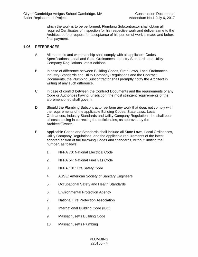
which the work is to be performed. Plumbing Subcontractor shall obtain all required Certificates of Inspection for his respective work and deliver same to the Architect before request for acceptance of his portion of work is made and before final payment.
1.06 REFERENCES
A. All materials and workmanship shall comply with all applicable Codes, Specifications, Local and State Ordinances, Industry Standards and Utility Company Regulations, latest editions.
B. In case of difference between Building Codes, State Laws, Local Ordinances, Industry Standards and Utility Company Regulations and the Contract Documents, the Plumbing Subcontractor shall promptly notify the Architect in writing of any such difference.
C. In case of conflict between the Contract Documents and the requirements of any Code or Authorities having jurisdiction, the most stringent requirements of the aforementioned shall govern.
D. Should the Plumbing Subcontractor perform any work that does not comply with the requirements of the applicable Building Codes, State Laws, Local Ordinances, Industry Standards and Utility Company Regulations, he shall bear all costs arising in correcting the deficiencies, as approved by the Architect/Owner.
E. Applicable Codes and Standards shall include all State Laws, Local Ordinances, Utility Company Regulations, and the applicable requirements of the latest adopted edition of the following Codes and Standards, without limiting the number, as follows:
1. NFPA 70: National Electrical Code
2. NFPA 54: National Fuel Gas Code
3. NFPA 101: Life Safety Code
4. ASSE: American Society of Sanitary Engineers
5. Occupational Safety and Health Standards
6. Environmental Protection Agency
7. National Fire Protection Association
8. International Building Code (IBC)
9. Massachusetts Building Code
10. Massachusetts Plumbing

City of Cambridge Amigos School Cambridge, MA Construction Documents Boiler Replacement Project Addendum No.1 July 6, 2017
PLUMBING 220100 - 5
F. In these specifications, references made to the following Industry Standards and Code Bodies are intended to indicate the latest volume or publication of the Standard. All equipment, materials and details of installation shall comply with the requirements and latest revisions of the following Bodies, as applicable:
1. ANSI: American National Standards Institute
2. ASTM: American Society of Testing Materials
3. MSS: Manufacturer’s Standardization Society of the Valve and Fittings Industry
4. ASME: American Society of Mechanical Engineering
5. AWS: American Welding Society
6. UL: Underwriters' Laboratories
1.07 QUALITY ASSURANCE
A. Refer to Section 01 40 00 for quality requirement in addition to the following part of this specification.
B. Refer to Section 01 25 00 of Division 1 –Substitution Procedures in addition to the following part if this specification.
C. The manufacturers listed within these specifications have been pre-selected for use on this project. Where equipment of a substitute manufacturer differs from that specified require different arrangements or connections from those shown, it shall be the responsibility of the Subcontractor responsible for the substitution to modify the installation of the equipment/system to operate properly and in harmony with the original intent of the drawings and specifications. When directed by the Architect, the Plumbing Subcontractor shall submit drawings showing the proposed, substitute installation. If the proposed installation is accepted, the Plumbing Subcontractor shall make all necessary changes in all affected related work provided under his and other Sections including location of roughing in connections by other Trades, conduit, supports, etc. All changes shall be made at no increase in the Contract amount or additional cost to the Owner. The General Contractor shall be responsible to assure that the Subcontractor responsible for the substitution bears the cost arising to all other Trades as a result of the substitution.
D. All substitutions shall be accompanied by a completed Substitution Request Cover Sheet contained within this section.
E. Plumbing Subcontractor shall furnish and install all equipment, accessories, connections and incidental items necessary to fully complete the work under his Contract for use, occupancy and operation by the Owner.
F. Unless specifically indicated otherwise, all equipment and materials required for installation under these specifications shall be new, unused and without blemish

City of Cambridge Amigos School Cambridge, MA Construction Documents Boiler Replacement Project Addendum No.1 July 6, 2017
PLUMBING 220100 - 6
or defect. Equipment and materials shall be products which will meet with the acceptance of the Authorities having jurisdiction over the work and as specified hereinbefore. Where such acceptance is contingent upon having the products listed and/or labeled by FM or UL or another testing laboratory, the products shall be so listed and/or labeled. Where no specific indication as to the type or quality of material or equipment is indicated, a first class standard article shall be provided.
G. The following substitution request sheet shall be copied on to the Contractor's letterhead, filled out, signed and sealed by an Authorized Officer of the Corporation then submitted to the Architect to be approved prior to any substitutions being considered, including all "equals” by manufacturers' not listed in the specifications.
SUBSTITUTION REQUEST COVER SHEET This cover sheet is required for all proposed substitutions including "or equal"s.
Contractor:
Subcontractor:

City of Cambridge Amigos School Cambridge, MA Construction Documents Boiler Replacement Project Addendum No.1 July 6, 2017
PLUMBING 220100 - 7
This Request Reference Number
Substitution Summary:
Specification Section and Paragraph Number:
Contract Drawing and Detail Reference:
Date of This Request:
This Request Prepared By:
Conditions: Indicate all conditions that apply to this proposed substitution:
[ ] Substitution required because specified item is no longer available.
[ ] Substitution required because Contractor believes specified item is incorrect, inappropriate, or incompatible.
[ ] Substitution recommended because it offers the Owner substantial advantage in:
[ ] Quality
[ ] Time
[ ] Cost
[ ] This is an "or equal".
Evidence: Indicate evidence attached:
[ ] Tabulated side by side comparison of specified item and proposed substitution directly comparing each feature, characteristic, and performance.
[ ] Manufacturer's product data for both specified item and proposed substitution. Origin of all information included on tabulated side by side comparison is highlighted.
[ ] Details showing how the proposed substitution interfaces with adjacent work.
[ ] Certification that warranty, if any required, will be provided as required.
[ ] Certification that this proposed substitution is coordinated with all related and adjacent work.
[ ] Complete cost change information.

City of Cambridge Amigos School Cambridge, MA Construction Documents Boiler Replacement Project Addendum No.1 July 6, 2017
PLUMBING 220100 - 8
[ ] Higher cost to Owner as stated in cost change information
[ ] No change in cost to Owner
[ ] Lower cost to Owner, credit to Owner as stated in cost change information
Deviations from Contract Documents: Itemize all deviations from Contract Documents if this proposed substitution is approved.
The undersigned attests that the undersigned has carefully examined this entire submission and that the requirements of the Contract Documents have been met.
Should this alternate material or equipment fail to meet the expectations of the owner within the mandated design liability period, this contractor shall replace the material and or equipment with the original specified items at no additional cost to the owner. This Subcontractor shall be responsible for all collateral impacts to the project for replacement of such deviations and substitutions. Firm: (seal)
By: Signature date
Printed or Typed Name Title
1.08 WARRANTY
A. Refer to provisions of the General Requirements and Supplementary General Requirements in Division 1 regarding warranties for work under this Contract.
B. All warranties shall begin on the Date of Substantial Completion of the entire project or the Owner’s acceptance of the workmanship and/or material covered
City of Cambridge Amigos School Cambridge, MA Construction Documents Boiler Replacement Project Addendum No.1 July 6, 2017
PLUMBING 220100 - 9
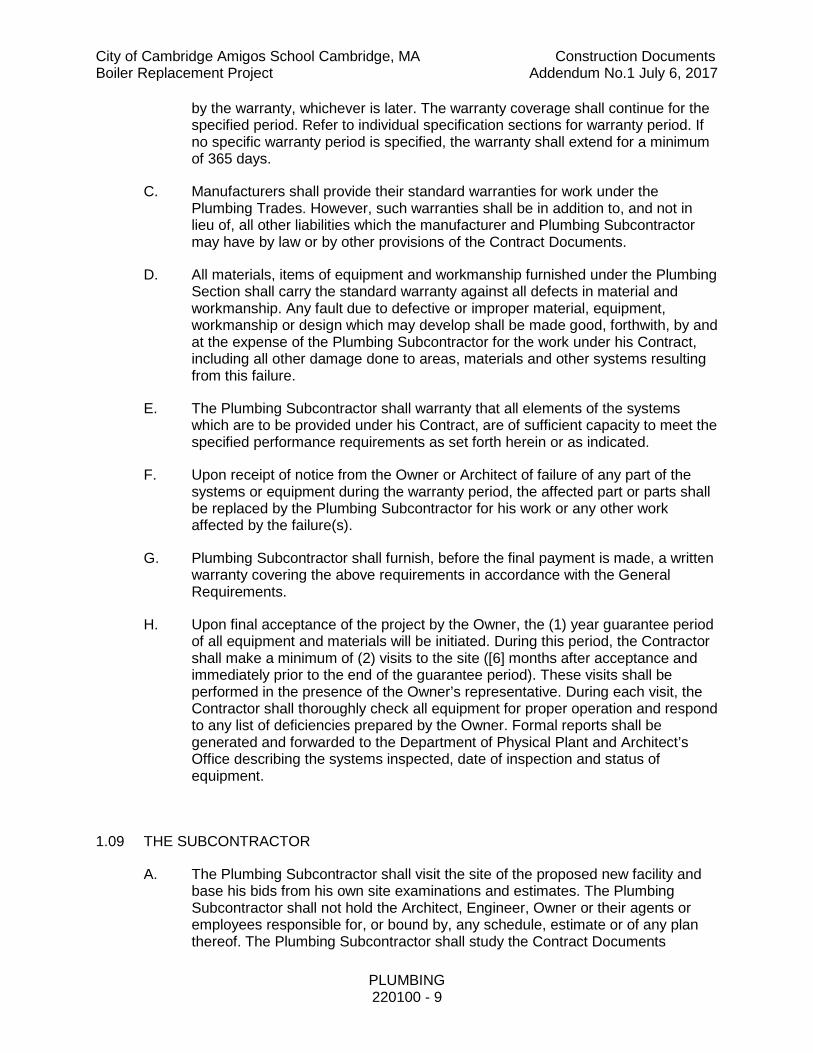
by the warranty, whichever is later. The warranty coverage shall continue for the specified period. Refer to individual specification sections for warranty period. If no specific warranty period is specified, the warranty shall extend for a minimum of 365 days.
C. Manufacturers shall provide their standard warranties for work under the Plumbing Trades. However, such warranties shall be in addition to, and not in lieu of, all other liabilities which the manufacturer and Plumbing Subcontractor may have by law or by other provisions of the Contract Documents.
D. All materials, items of equipment and workmanship furnished under the Plumbing Section shall carry the standard warranty against all defects in material and workmanship. Any fault due to defective or improper material, equipment, workmanship or design which may develop shall be made good, forthwith, by and at the expense of the Plumbing Subcontractor for the work under his Contract, including all other damage done to areas, materials and other systems resulting from this failure.
E. The Plumbing Subcontractor shall warranty that all elements of the systems which are to be provided under his Contract, are of sufficient capacity to meet the specified performance requirements as set forth herein or as indicated.
F. Upon receipt of notice from the Owner or Architect of failure of any part of the systems or equipment during the warranty period, the affected part or parts shall be replaced by the Plumbing Subcontractor for his work or any other work affected by the failure(s).
G. Plumbing Subcontractor shall furnish, before the final payment is made, a written warranty covering the above requirements in accordance with the General Requirements.
H. Upon final acceptance of the project by the Owner, the (1) year guarantee period of all equipment and materials will be initiated. During this period, the Contractor shall make a minimum of (2) visits to the site ([6] months after acceptance and immediately prior to the end of the guarantee period). These visits shall be performed in the presence of the Owner’s representative. During each visit, the Contractor shall thoroughly check all equipment for proper operation and respond to any list of deficiencies prepared by the Owner. Formal reports shall be generated and forwarded to the Department of Physical Plant and Architect’s Office describing the systems inspected, date of inspection and status of equipment.
1.09 THE SUBCONTRACTOR
A. The Plumbing Subcontractor shall visit the site of the proposed new facility and base his bids from his own site examinations and estimates. The Plumbing Subcontractor shall not hold the Architect, Engineer, Owner or their agents or employees responsible for, or bound by, any schedule, estimate or of any plan thereof. The Plumbing Subcontractor shall study the Contract Documents

City of Cambridge Amigos School Cambridge, MA Construction Documents Boiler Replacement Project Addendum No.1 July 6, 2017
PLUMBING 220100 - 10
included under this Contract to determine exactly the extent of work provided under this Contract, as well as to ascertain the difficulty to be encountered in performing the work, in installing new equipment and systems and coordinating the work with the other Trades and existing building conditions.
B. The Plumbing Subcontractor shall faithfully execute his work according to the terms and conditions of the Contract and specifications, and shall take all responsibility for and bear all losses resulting to him in the execution of his work.
C. The Plumbing Subcontractor shall be responsible for the location and performance of work provided under his Contract as indicated on the Contract Documents. All parties employed directly or indirectly by the Plumbing Subcontractor shall perform their work according to all the conditions as set forth in these specifications.
D. The Plumbing Subcontractor shall furnish all materials and do all work in accordance with these specifications, and any supplementary documents provided by the Architect. The work shall include everything shown on the drawings and/or required by the specifications as interpreted by the Architect, regardless of where such information is indicated in the Contract Documents (Architectural, HVAC, Plumbing, Fire Protection, etc.). Unless specifically indicated otherwise, all work and materials furnished and installed shall be new, unused and of the best quality and workmanship. The Plumbing Subcontractor shall cooperate with the Architect so that no error or discrepancy in the Contract Documents shall cause defective materials to be used or poor workmanship to be performed.
1.10 COORDINATION OF WORK
A. The Plumbing Subcontractor shall compare his drawings and specifications with those of other Trades as well as the Architectural drawings and specifications, and report any discrepancies between them to the Architect and obtain from the Architect written instructions for changes necessary in the plumbing work.
B. Coordinate work with that of all other Trades affecting or affected by the work of this Section. Cooperate with such Trades to assure the steady progress of all work under the Contract.
C. All work shall be installed in cooperation with other Trades installing interrelated work. Before installation, Plumbing Subcontractor shall make proper provisions to avoid interferences in a manner approved by the Architect. All changes required in the work of the Plumbing Subcontractor or that of any other trade caused by the Plumbing Subcontractor's neglect, shall be made by him at his own expense, and to the Architect's satisfaction.
D. The Plumbing Subcontractor shall include in his bid sufficient dollar amounts to coordinate the work of this Contract. This project MAY require additional time to coordinate all Trades and allow implementation of the Owner’s Standards and maintenance serviceability requirements. This requirement shall include, but not be limited to, producing the coordination drawings, as many times and as many

City of Cambridge Amigos School Cambridge, MA Construction Documents Boiler Replacement Project Addendum No.1 July 6, 2017
PLUMBING 220100 - 11
drawings as required, to ensure serviceability of equipment, as approved by the Architect.
E. Locations of pipes and equipment, etc. shall be adjusted to accommodate the work with interferences anticipated and encountered. The Plumbing Subcontractor shall determine the exact routing and location of his systems prior to fabrication or installation of any system component. Accurate measurements and coordination drawings shall be completed to verify dimensions and characteristics of the various systems installations.
F. Lines which pitch shall have the right-of-way over those which do not pitch. For example, gravity drainage piping shall normally have the right-of-way. Lines whose elevations cannot be changed shall have the right-of-way over lines whose elevations can be changed.
G. Offsets, transitions and changes of direction in all systems shall be made as required to maintain proper headroom and pitch of sloping lines whether or not indicated on the drawings. The Plumbing Subcontractor shall provide offsets and materials and labor required to achieve these offsets etc. as required for his work to effect these offsets, transitions and changes in direction.
H. All work shall be installed in a way to permit removal (without damage to other parts) of coils, filters, control appurtenances, belts and belt guards, drives, sheaves and all other system components provided under this Contract requiring periodic replacement or maintenance. All piping and appurtenances shall be arranged in a manner to clear the openings of swinging overhead access doors as well as ceiling tiles. All work shall be done to allow easy access for maintaining equipment. The Owner and Engineer will require proof via the preparation of large scale sections and part plans that all components are accessible after the work is completed. Any items in the field discovered to be in non-compliance shall be removed and relocated, as required, and as directed by the Architect and at no cost to the Owner.
I. The Contract Drawings are diagrammatic only intending to show general runs and locations of piping, equipment, etc. and not necessarily showing all required offsets, details and accessories and equipment to be connected. All work shall be accurately laid out with other Trades to avoid conflicts and to obtain a neat and workmanlike installation which will afford maximum accessibility for operation, maintenance and headroom.
J. Where discrepancies in scope of work as to what Trade provides items, such as starters, disconnects, flow switches, alarm points, etc., exist, such conflicts shall be reported to the Architect during bidding and prior to signing of the Contract. If such action is not taken, the Plumbing Subcontractor shall furnish such items as part of his work as necessary, for complete and operable systems and equipment, as determined by the Architect.
K. Where drawing details, plans, specification requirements and/or scheduled equipment capacities are in conflict and where piping or equipment are shown to be different (including pipe sizes) between plans and/or between plans and riser diagrams, details or specifications, the most stringent requirement will be

City of Cambridge Amigos School Cambridge, MA Construction Documents Boiler Replacement Project Addendum No.1 July 6, 2017
PLUMBING 220100 - 12
included in the Contract. Plumbing systems and equipment called for in the specification and/or shown on the drawings shall be provided under this Contract as if it were required by both the drawings and specifications. However, prior to ordering or installation of any portion of work which appears to be in conflict, such work shall be brought to Architect's attention for direction as to what is to be provided.
L. The Plumbing Subcontractor shall coordinate his work with other Trades' work so that all equipment and systems can be easily, safety and properly serviced and maintained. It is imperative that service personnel can safely access all equipment.
1.11 GIVING INFORMATION
A. Plumbing Subcontractor shall keep himself fully informed as to the shape, size and position of all openings required for his equipment and shall give information to the General Contractor and other Subcontractors sufficiently in advance of the work so that all openings may be built in advance.
1.12 EQUIPMENT AND MATERIALS
A. All Equipment of one type (such as valves, pumps, water heaters, etc.,) shall be the product of one manufacturer, unless noted otherwise in this specification.
B. Equipment and materials shall be delivered to the site and stored in original sealed containers, suitably sheltered from the elements, but readily accessible for inspection by the Architect until installed. All items subject to moisture damage such as switches, controls, etc., shall be stored in dry, heated spaces.
C. Equipment shall be tightly covered and protected against dirt, water, and chemical or mechanical injury and theft. At the completion of the work, equipment and materials shall be cleaned and polished thoroughly and turned over to the Owner in a condition satisfactory to the Architect. Damage or defects that develop before acceptance of the work shall be made good at the Plumbing Subcontractor's expense.
D. The Plumbing Subcontractor shall make necessary field measurements to ascertain space requirements, for equipment and connections to be provided under his respective Trade and shall furnish and install such sizes and shapes of equipment to allow for the final installation to conform to the drawings and specifications.
E. Manufacturers’ directions shall be followed completely in the delivery, storage, protection and installation. Promptly notify the Architect in writing of any conflict between any requirements of the Contract Documents and the manufacturer's directions. Obtain the Architect's written instructions before proceeding with the work. Should Plumbing Subcontractor perform any work that does not comply with the manufacturer's directions or written instructions from the Architect, he shall bear all costs arising in correcting any deficiencies that should arise.

City of Cambridge Amigos School Cambridge, MA Construction Documents Boiler Replacement Project Addendum No.1 July 6, 2017
PLUMBING 220100 - 13
F. Equipment pre-purchased by the General Contractor on behalf of the Owner or by the Owner himself, if assigned to the Plumbing Subcontractor, shall be received, installed, tested, etc., as if the equipment was purchased by the Plumbing Subcontractor. All guarantees, service contracts, etc., shall be the same as for all other equipment provided under this Contract.
G. Refer to Section 01 25 00 of Division 1 – Substitution Procedures for the requirements of this Section.
H. The manufacturers listed within this specification have been preselected for use on this project. Where equipment of a substitute manufacturer differs from that specified require different arrangements or connections from those shown, it shall be the responsibility of the Subcontractor responsible for the substitution to modify the installation of the equipment/system to operate properly and in harmony with the original intent of the drawings and specifications. Should the Plumbing Subcontractor wish to propose a substitution during the bid period, such request shall be made in writing to the Architect, no less than seven (7) working days, prior to bid date. If substitutions are deemed acceptable, such items shall be issued on as an Addendum by the contractor, prior to bid due date The above requirement is mandatory.
I. All substitutions shall be accompanied by a completed Substitution Request Cover Sheet contained within this section of the specifications.
J. The Plumbing Subcontractor shall furnish and install all equipment, accessories, connections and incidental items necessary to fully complete the work under his Contract for use, occupancy and operation by the Owner.
K. All equipment and materials required for installation under these specifications shall be new and without blemish or defect. Equipment and materials shall be products which will meet with the acceptance of the Authorities having jurisdiction over the work and as specified hereinbefore. Where such acceptance is contingent upon having the products listed or labeled by FM, UL or other testing laboratories, the products shall be so listed or labeled. Where no specific indication as to the type or quality of material or equipment is indicated, a first class standard article shall be provided.
1.13 USE OF PREMISES
A. The Plumbing Subcontractor shall confine all apparatus, storage of materials and construction to the limits as directed by the Architect and he shall not encumber the premises with his materials. The Plumbing Subcontractor shall be held responsible for repairs, patching, or cleaning arising from any unauthorized use of premises.
B. In storing materials within areas (structure or ground), or when used as a shop, the Plumbing Subcontractor shall consult with the Construction Manager and shall restrict his storage to space designated for such purposes. The Plumbing

City of Cambridge Amigos School Cambridge, MA Construction Documents Boiler Replacement Project Addendum No.1 July 6, 2017
PLUMBING 220100 - 14
Subcontractor will be held responsible for repairs, loss, patching or cleaning arising from any unauthorized use of the premises.
C. Notwithstanding any approvals or instructions which must be obtained by the Plumbing Subcontractor from the Architect in connection with the use of the premises, the responsibility for the safe working conditions at the site shall remain that of the Plumbing Subcontractor. The Architect, Engineer or Owner shall not be deemed to have any responsibility or liability in connection with safe working conditions at the site.
1.14 PROTECTION
A. Materials, such as valves, pipes, fittings, pumps, water heaters, plumbing fixtures, drains, etc., shall be properly protected during construction and all pipe openings shall be temporarily closed so as to prevent obstruction and damage. Post notice prohibiting the use of all systems provided under the Plumbing Contract, prior to completion of work and acceptance of all systems by the Owner except as otherwise instructed by Architect. Take precautions to protect all materials furnished from damage and theft.
B. The Plumbing Subcontractor shall furnish, place and maintain proper safety guards for the prevention of accidents that might be caused by the workmanship, materials, equipment or electrical systems provided under his Contract.
1.15 DAMAGE TO OTHER WORK
A. The Plumbing Subcontractor shall be held responsible and shall pay for all damages caused by his work to the building structures, equipment, conduits, systems, etc., and all work and finishes installed under this Contract. Repair of such damage shall be done by the General Contractor at the expense of the Plumbing Subcontractor, to the Architect's satisfaction.
1.16 CORRECTION OF WORK
A. The Plumbing Subcontractor shall promptly correct all work provided under his Contract and rejected by the Architect as defective or as failing to conform to the Contract Documents, whether observed before or after completion of work, and whether or not fabricated, installed or completed.
1.17 EXTRA WORK
A. No claim for extra work will be allowed unless it is authorized by the Architect in writing before commencement of the extra said work.
1.18 TOUCH-UP PAINTING
A. All equipment and systems shall be thoroughly cleaned of rust, splatters and other foreign matter or discoloration leaving every part of all systems in an acceptable prime condition. The Plumbing Subcontractor, for the work under his Contract, shall refinish and restore to the original condition all equipment which have sustained damage to the manufacturer's prime and finish coats of paint

City of Cambridge Amigos School Cambridge, MA Construction Documents Boiler Replacement Project Addendum No.1 July 6, 2017
PLUMBING 220100 - 15
and/or enamel during the course of construction, regardless of the source of damage.
1.19 MANUFACTURER'S REPRESENTATIVE
A. The Plumbing Subcontractor shall provide, at appropriate time or as directed by the Architect, the on-site services of a competent factory trained Engineer or authorized representative of particular manufacturer of equipment such as for the domestic water booster pump, hot water heater, sump pumps, sewage ejectors, hot water circulation pumps and controls, mixing valves , etc., provided under this Contract, to instruct the Owner, inspect, adjust and place in proper operating condition any item provided by him, as applicable. As a minimum, system start-up/commissioning shall start 90 days prior to scheduled building occupancy.
B. The Plumbing Subcontractor, as applicable, shall commission and set in operating condition all major equipment and systems, such as the domestic water booster pump, hot water heater, sump pumps, sewage ejectors, hot water circulation pumps and controls, mixing valves, in the presence of the equipment manufacturer’s representatives, as applicable, and the Owner and Architect’s representatives. In no case will major systems and equipment be commissioned by any of the Subcontractor’s forces alone, without the assistance or presence of the equipment manufacturer representative.
C. A written report shall be issued by the particular equipment manufacturer and the Plumbing Subcontractor summarizing the results of the commissioning and performance of each system for the Architect’s record. No additional compensation will allowed for any Contractor for such services.
1.20 RECORD DRAWINGS/AS-BUILT DRAWINGS
A. The Plumbing Subcontractor shall maintain current at the site a set of his drawings on which he shall accurately show the actual installation of all work provided under his Contract indicating hereon any variation from the Contract Drawings, in accordance with the General Conditions and Division 1. Changes, whether resulting from formal change orders or other instructions issued by the Architect, shall be recorded. Include changes in sizes, location, and dimensions of piping, equipment, fixtures, etc.
B. The Plumbing Subcontractor shall indicate progress by coloring-in various piping, equipment and associated appurtenances exactly as they are erected. This process shall incorporate both the changes noted above and all other deviations from the original drawings whether resulting from job conditions encountered or from any other causes.
C. The marked-up and colored-up prints will be used as a guide for determining the progress of the work installed. They shall be inspected periodically by the Architect and Owner and they shall be corrected immediately if found either inaccurate or incomplete. This procedure is mandatory.
Failure to comply with this requirement could result in a reduction of the monthly payment requisition recommended.

City of Cambridge Amigos School Cambridge, MA Construction Documents Boiler Replacement Project Addendum No.1 July 6, 2017
PLUMBING 220100 - 16
D. At the completion of the job, these prints shall be submitted to the General Contractor and then to the Architect for final review and comment. The prints will be returned with appropriate comments and recommendations. These corrected prints, together with corrected prints indicating all the revisions, additions and deletions of work, shall form the basis for preparing a set of As-Built Record Drawings.
E. The Plumbing Subcontractor shall be responsible for generating As-Built Record Drawings utilizing CAD based documents in AutoCAD (latest version) format. A bound set of plans, as well as the computer files, on disk, shall be turned over to the Architect for review. After acceptance of the As-Built documents by the Architect, the Plumbing Subcontractor shall make any corrections necessary to the As-Built documents and prepare one reproducible set of drawings as well as bound blueprint set(s) (quantity as determined by the Architect) for distribution to the Owner via the Architect.
F. The Plumbing Subcontractor may use the computer drawing files used for coordination drawings or obtain the Engineers most recently updated computer drawing files. The updated drawings may not include all changes made during the course of construction and it shall be the Plumbing Subcontractors responsibility to update the As-Built documents to include all changes brought forth to the project resulting from bulletins, request for information (RFI's), change orders, etc. The Engineer will not be responsible for updating the computer files.
G. Included with the above shall be a complete drawing list and a standard layering system, which shall be required to be maintained within the As-Built Record AutoCAD (latest version) documents.
H. As-builts shall be delivered to the owner in electronic format in AutoCAD (Latest Version) and PDF.
I. The As-Built AutoCAD (latest version) documents required shall be in addition to other requirements stated elsewhere.
1.21 SHOP DRAWING SUBMITTALS
A. Prepare and submit shop drawings in accordance with the requirements herein before specified, and with the Shop Drawings, Product Data and Samples in Division 1 in the manner described therein, modified as noted hereinafter.
B. All shop drawings shall have clearly marked the appropriate specification number of drawing designation, for identification of the submittal.
C. Disposition of shop drawings shall not relieve the Plumbing Subcontractor from the responsibility for deviations from drawing or specifications, unless he has submitted in writing a letter itemizing or calling attention to such deviations at time of submission and secured written approval from the Engineer, nor shall such disposition of shop drawings relieve the Plumbing Subcontractor from responsibility for errors in shop drawings or schedules.

City of Cambridge Amigos School Cambridge, MA Construction Documents Boiler Replacement Project Addendum No.1 July 6, 2017
PLUMBING 220100 - 17
D. Shop drawing data shall include, but not be limited to, the following:
1. Manufacturer’s model and catalog data.
2. Complete connection diagrams for all Trades.
3. Dimensions, capacities, ratings, materials, finishes, etc.
E. Each shop drawing is required to bear the review stamp of each Contractor associated with installing the equipment and/or processing the document.
F. All final approved shop drawings shall be included in the required O & M manuals.
G. Shop drawings shall include but shall not be limited to the following:
1. Plumbing work layout, including location and sizes of piping, valves, equipment, connections, and all other accessories
2. Equipment cuts and manufacturer’s documentation for
a. Equipment
b. Piping and fittings
c. Pipe sleeves, plates and escutcheons
d. Fire stopping and smoke stopping,
e. Valves, gauges, drains, thermometers
f. Hangers, supports, fasteners
g. Pumps and control panels
h. Water heaters
i. Manifolds
j. Regulators
1.22 MISCELLANEOUS IRON AND STEEL
A. Except where specifically indicated for the General Contractor to provide supports, Plumbing Subcontractor shall provide all steel supports and hangers required to support all equipment or materials provided under this Contract.
B. All supports shall be cut, assembled, welded and finished by skilled mechanics. Welds shall be ground smooth. Stands, brackets and framework shall be properly sized and strongly constructed.
City of Cambridge Amigos School Cambridge, MA Construction Documents Boiler Replacement Project Addendum No.1 July 6, 2017
PLUMBING 220100 - 18
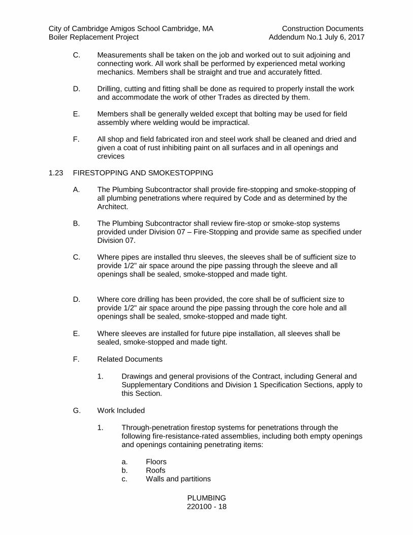
C. Measurements shall be taken on the job and worked out to suit adjoining and connecting work. All work shall be performed by experienced metal working mechanics. Members shall be straight and true and accurately fitted.
D. Drilling, cutting and fitting shall be done as required to properly install the work and accommodate the work of other Trades as directed by them.
E. Members shall be generally welded except that bolting may be used for field assembly where welding would be impractical.
F. All shop and field fabricated iron and steel work shall be cleaned and dried and given a coat of rust inhibiting paint on all surfaces and in all openings and crevices
1.23 FIRESTOPPING AND SMOKESTOPPING
A. The Plumbing Subcontractor shall provide fire-stopping and smoke-stopping of all plumbing penetrations where required by Code and as determined by the Architect.
B. The Plumbing Subcontractor shall review fire-stop or smoke-stop systems provided under Division 07 – Fire-Stopping and provide same as specified under Division 07.
C. Where pipes are installed thru sleeves, the sleeves shall be of sufficient size to provide 1/2" air space around the pipe passing through the sleeve and all openings shall be sealed, smoke-stopped and made tight.
D. Where core drilling has been provided, the core shall be of sufficient size to
provide 1/2" air space around the pipe passing through the core hole and all openings shall be sealed, smoke-stopped and made tight.
E. Where sleeves are installed for future pipe installation, all sleeves shall be sealed, smoke-stopped and made tight.
F. Related Documents 1. Drawings and general provisions of the Contract, including General and
Supplementary Conditions and Division 1 Specification Sections, apply to this Section.
G. Work Included 1. Through-penetration firestop systems for penetrations through the
following fire-resistance-rated assemblies, including both empty openings and openings containing penetrating items: a. Floors b. Roofs c. Walls and partitions

City of Cambridge Amigos School Cambridge, MA Construction Documents Boiler Replacement Project Addendum No.1 July 6, 2017
PLUMBING 220100 - 19
d. Smoke barriers e. Construction enclosing compartmentalized areas. f. Other rated assemblies.
H. Related Sections
1. Examine all drawings and criteria sheets and all other Sections of the
Specifications for requirements which affect work under this Section whether or not such work is specifically mentioned in this Section.
I. References 1. American Society for Testing and Materials Standards (ASTM):
a. ASTM E84: Standard Test Method for Surface Burning
Characteristics of Building Materials b. ASTM E814: Standard Test Methods for Fire Tests of Through-
Penetration Firestops c. ASTM E119: Standard Test Methods for Fire Tests of Building
Construction Materials d. ASTM E1966: Standard Test Methods for Fire Tests of Joints e. ASTM E 2174: Standard Practice for On-Site Inspection of
Installed Fire Stops
2. Underwriters Laboratories, Inc. (UL): a. UL 723 Surface Burning Characteristics of Building Materials b. UL 1479 Fire Tests of Through-Penetration Firestops, including
optional water leakage and air leakage tests c. UL 2079 Fire Test of Building Joint Firestop systems d. UL Fire Resistance Firestop Devices (XHJI)
3. National Fire Protection Agency (NFPA)
a. NFPA 101 Life Safety Code b. NEC 70 National Electrical Code c. International Firestop Council Guidelines for Evaluating Firestop
Systems Engineering Judgments
J. Performance Requirements 1. General: For the following constructions, provide through-penetration
firestop systems that are produced and installed to resist spread of fire according to requirements indicated, resist passage of smoke and other gases, and maintain original fire-resistance rating of assembly penetrated.
a. Fire-resistance-rated load-bearing walls, including partitions, with
fire-protection-rated openings.
City of Cambridge Amigos School Cambridge, MA Construction Documents Boiler Replacement Project Addendum No.1 July 6, 2017
PLUMBING 220100 - 20
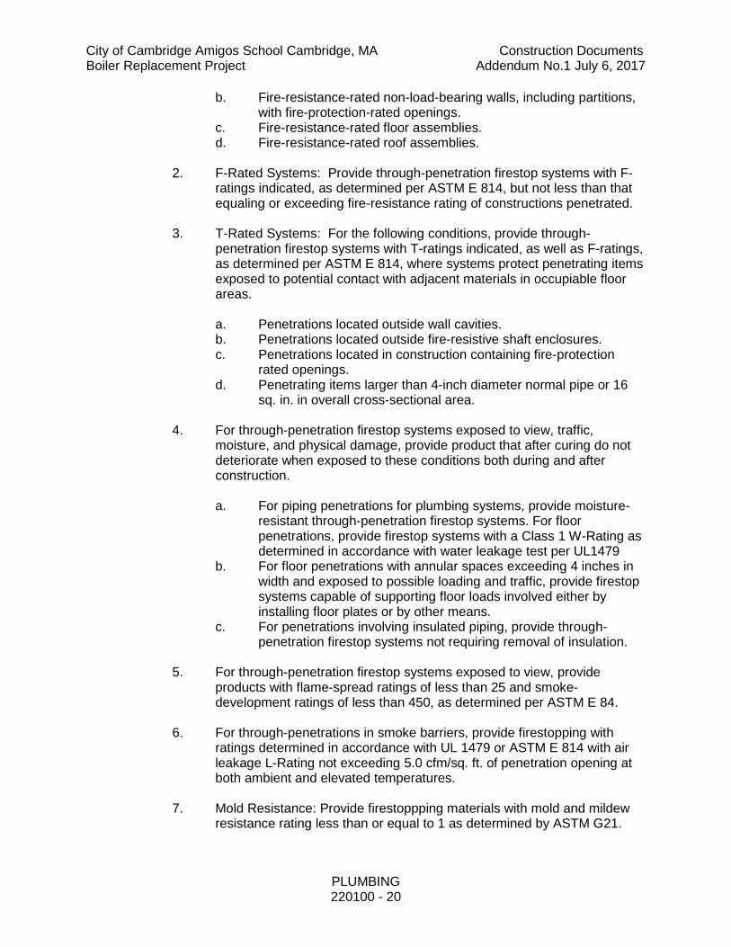
b. Fire-resistance-rated non-load-bearing walls, including partitions, with fire-protection-rated openings.
c. Fire-resistance-rated floor assemblies. d. Fire-resistance-rated roof assemblies.
2. F-Rated Systems: Provide through-penetration firestop systems with F-
ratings indicated, as determined per ASTM E 814, but not less than that equaling or exceeding fire-resistance rating of constructions penetrated.
3. T-Rated Systems: For the following conditions, provide through-
penetration firestop systems with T-ratings indicated, as well as F-ratings, as determined per ASTM E 814, where systems protect penetrating items exposed to potential contact with adjacent materials in occupiable floor areas.
a. Penetrations located outside wall cavities. b. Penetrations located outside fire-resistive shaft enclosures. c. Penetrations located in construction containing fire-protection
rated openings. d. Penetrating items larger than 4-inch diameter normal pipe or 16
sq. in. in overall cross-sectional area.
4. For through-penetration firestop systems exposed to view, traffic, moisture, and physical damage, provide product that after curing do not deteriorate when exposed to these conditions both during and after construction.
a. For piping penetrations for plumbing systems, provide moisture-
resistant through-penetration firestop systems. For floor penetrations, provide firestop systems with a Class 1 W-Rating as determined in accordance with water leakage test per UL1479
b. For floor penetrations with annular spaces exceeding 4 inches in width and exposed to possible loading and traffic, provide firestop systems capable of supporting floor loads involved either by installing floor plates or by other means.
c. For penetrations involving insulated piping, provide through-penetration firestop systems not requiring removal of insulation.
5. For through-penetration firestop systems exposed to view, provide
products with flame-spread ratings of less than 25 and smoke-development ratings of less than 450, as determined per ASTM E 84.
6. For through-penetrations in smoke barriers, provide firestopping with ratings determined in accordance with UL 1479 or ASTM E 814 with air leakage L-Rating not exceeding 5.0 cfm/sq. ft. of penetration opening at both ambient and elevated temperatures.
7. Mold Resistance: Provide firestoppping materials with mold and mildew resistance rating less than or equal to 1 as determined by ASTM G21.

City of Cambridge Amigos School Cambridge, MA Construction Documents Boiler Replacement Project Addendum No.1 July 6, 2017
PLUMBING 220100 - 21
K. Submittals
1. See Division 01 and 07 for Additional Requirements.
2. Product Data: For each type through-penetration firestop system product indicated.
3. Shop Drawings: For each through-penetration firestop system show each kind of construction condition penetrated, relationships to adjoining construction, and kind of penetrating items. Include firestop design designation of testing and inspecting agency acceptable to authorities having, jurisdiction that evidences compliance with requirements for each condition indicated.
a. Submit documentation, including illustrations, from a qualified
testing and inspecting agency that is applicable to each through-penetration firestop system configuration for construction and penetrating items.
b. For those firestop applications that exist for which no qualified tested system is available through a manufacturer, an engineering judgment derived from similar qualified tested system designs or other tests will be submitted to local authorities having jurisdiction for their review and approval prior to installation. Engineering judgment documents must follow requirements set forth by the International Firestop Council.
4. Submit complete plans indicating clearly where all seals are located and
the type of seal to be used at that location.
5. Qualification Data: For firms and persons specified to demonstrate their capabilities and experience. Include lists of completed projects with project names and addresses, names and addresses of architects and owners, and other information specified.
6. Product Certificates: Signed by manufacturers of through-penetration firestop system products certifying that products furnished comply with requirements.
7. Product Test Reports: From a qualified testing agency indicating through-
penetration firestop system complies with requirements, based on comprehensive testing of current products.
8. Material Safety Data Sheets: Submit material safety data sheets provided
with product delivered to job-site.
L. Quality Assurance
1. Installer Qualifications: Engage an experienced Installer who is certified, licensed, or otherwise qualified by the firestopping manufacturer as having been provided the necessary training to install manufacturer’s

City of Cambridge Amigos School Cambridge, MA Construction Documents Boiler Replacement Project Addendum No.1 July 6, 2017
PLUMBING 220100 - 22
products per specified requirements. A supplier’s willingness to sell its firestopping products to the Contractor or to an Installer engaged by the Contractor does not in itself confer qualification on the buyer.
2. Installation Responsibility: Assign installation of through-penetration firestop systems in Project to a single sole source firestop specialty contractor with at least one of the following qualifications:
a. FM 4991 Approved Contractor b. UL Approved Contractor c. Hilti Accredited Firestop Specialty Contractor
3. Source Limitations: Obtain through-penetration firestop systems, for each
kind of penetration and construction condition indicated, from a single manufacturer.
4. Fire-Test-Response Characteristics: Provide through-penetration firestop
systems that comply with the following requirements and those specified in “Performance Requirements” Article:
a. Through-Penetration Firestop Systems tests are performed by a
qualified testing and inspecting agency. A qualified testing and inspecting agency is UL, ITS, or another agency performing testing and follow-up inspection services for firestop systems acceptable to authorities having jurisdiction.
b. Through-penetration firestop systems are identical to those tested per ASTM E 814. Provide rated systems complying with the following requirements: 1) Through-penetration firestop system products hear
classification marking of qualified testing and inspecting agency.
2) Through-penetration firestop systems correspond to those indicated by reference to through-penetration firestop system designations listed by the following: a) UL in “Fire Resistance Directory.” b) ITS in “Directory of Listed Products.”
M. Delivery, Storage, And Handling
1. Deliver through-penetration firestop system products to Project site in
original, unopened containers or packages with intact and legible manufacturers’ labels identifying product and manufacturer, date of manufacture; lot number; shelf life, if applicable, qualified testing and inspecting agency’s classification marking applicable to Project; curing time; and mixing instructions for multicomponent materials.

City of Cambridge Amigos School Cambridge, MA Construction Documents Boiler Replacement Project Addendum No.1 July 6, 2017
PLUMBING 220100 - 23
2. Store and handle materials for through-penetration firestop systems to prevent their deterioration or damage due to moisture, temperature changes, contaminants, or other causes.
N. Project Conditions
1. Environmental Limitations: Do not install through-penetration fires top
systems when ambient or substrate temperatures are outside limits permitted by through penetration firestop system manufacturers or when substrates are wet due to rain, frost, condensation, or other causes.
2. Ventilate through-penetration firestop systems per manufacturer’s written instructions by natural means or, where this is inadequate, forced-air circulation.
O. Coordination
1. Coordinate construction of openings and penetrating items to ensure that
through-penetration firestop systems are installed according to specified requirements.
2. Coordinate sizing of sleeves, openings, core-drilled holes, or cut openings to accommodate through-penetration firestop systems.
3. Notify Owner’s inspecting agency at least seven days in advance of through-penetration firestop system installations; confirm dates and times on days preceding each series of installations.
4. Do not cover up through-penetration firestop system installations that will become concealed behind other construction until Owner’s inspecting agency and building inspector, if required by authorities having jurisdiction, have examined each installation.
1.24 DEMOLITION AND MAINTAINING EXISTING SERVICES
A. During the execution of the work, required relocation, rerouting, etc., of existing equipment and systems on the site or where new work is to be installed or new connections are scheduled to be made, shall be performed by the Plumbing Subcontractor, as indicated on the drawings, and/or as required by job conditions and as determined by the Architect in the field, to facilitate the installation of the new systems.
B. The Owner will require continuous operation of the existing systems, while demolition, relocation work or new tie-ins will be performed. Outages required for construction purposes shall be scheduled for the shortest practical periods of time, in coordination with the Owner's designated representative, for specified, mutually agreeable periods of time, after each of which the interruption shall cease and the service shall be restored. This procedure shall be repeated to suit the Owner's working schedule, as many times as required until all work is completed. Any outages of service shall be approved by the Owner, prior to

City of Cambridge Amigos School Cambridge, MA Construction Documents Boiler Replacement Project Addendum No.1 July 6, 2017
PLUMBING 220100 - 24
commencing the work. No outages or shutdowns of service shall occur without the written authorization of the Owner, prior to commencing the work. Give notice of any scheduled shutdowns, a minimum of two (2) weeks in advance. The Owner shall make their best efforts to meet this request without adversely affecting the electric service to the site.
C. Shutdowns shall not be scheduled during normal business hours (i.e., shutdowns shall be from 6:00 PM to 6:00 AM). Maximum duration of each shutdown shall be eight (8) hours, unless otherwise approved by the Owner. Not more than one shutdown per twenty-four 24 hour period, unless otherwise approved by the Owner.
D. The Plumbing Subcontractor shall submit with his bid a preliminary shutdown schedule for review by the Owner, Architect and General Contractor. Shutdown schedule shall be finalized with the successful Plumbing Subcontractor.
E. Prior to any deactivation and relocation or demolition work, consult the drawings and arrange a conference with the Architect and the Owner's representative in the field to inspect each of the items to be deactivated, removed or relocated. Care shall be taken to protect all equipment designated to be relocated and reused or to remain in operation and be integrated with the new systems.
F. Refer to Division 1 for additional requirements for demolition and extension of existing systems.
G. Plumbing Subcontractor shall be responsible to disconnect, make safe and lower to ground all piping, fixtures equipment indicated for removal. Piping and all associated supports shall be removed in their entirety, unless otherwise noted on the drawings.
H. Plumbing Subcontractor shall disconnect and make safe all equipment designated for removal by others.
I. All deactivation, relocation and temporary tie-ins shall be provided by the Plumbing Subcontractor. All demolition, removal and the legal disposal of demolished materials of system designated to be demolished shall be provided by the General Contractor.
J. The Owner reserves the right to inspect the material scheduled for removal, and salvage any items he deems usable as spare parts.
K. Where existing piping and equipment are embedded in concrete walls, ceilings or floors, the piping shall be cut back flush to the surface, all piping shall be disconnected equipment shall be removed for the General Contractor to patch the existing opening.
1.25 CORE DRILLING
A. The Plumbing Contractor shall be responsible for core drilling all holes required for work under his Contract and with the written approval of the Architect.

City of Cambridge Amigos School Cambridge, MA Construction Documents Boiler Replacement Project Addendum No.1 July 6, 2017
PLUMBING 220100 - 25
B. In no case shall the Plumbing Contractor cut into any structural elements without the written approval of the Architect
1.26 PIPE SLEEVES AND ESCUTCHEONS
A. Where pipes pass through all wall or floors, the Plumbing Contractor shall provide and set individual sleeves for each pipe and all other work under his charge, as necessary for passage of all pipes. Sleeves shall be of sufficient size to provide ½ inch air space around the pipe passing through it. All openings shall be sealed, smokeproofed and made tight. The Plumbing Contractor shall be responsible for the exact location of sleeves provided under this Contract and shall coordinate all requirements for piping sleeves.
B. All exposed piping penetration of walls, floors, and ceilings shall be fitted with escutcheons.
C. When plastic piping is used the penetration shall be protected with a fire rated collar to maintain the assembly rating.
1.27 IDENTIFICATION OF MATERIALS
A. All equipment used in the plumbing systems shall have a permanently attached nameplate identifying the manufacturer, service, size, serial number or model number, etc. The nameplates shall be kept clean and readable at all times.
B. Each item of equipment such as pumps, water heaters, grease traps, interceptors, etc., shall be identified by a permanently attached nameplate.
C. A legend showing the service and an arrow indicating the direction of flow shall be applied on each pipe installed by the Plumbing Subcontractor.
1.28 VALVE TAGS AND CHARTS
A. All valves on pipes of every description shall be provided with valve tags. Tags shall be provided by the Plumbing Subcontractor for the work under their charge.
B. All valves on equipment shall be provided with valve tags.
C. The Plumbing Subcontractor shall provide for his work valve charts of all systems.
PART 2 – PRODUCTS
2.01 GENERAL
A. All materials submitted for use on this project shall be manufactured in North America unless there is no source of supply available to meet this criteria. Source documentation shall be submitted upon request.

City of Cambridge Amigos School Cambridge, MA Construction Documents Boiler Replacement Project Addendum No.1 July 6, 2017
PLUMBING 220100 - 26
B. All piping, fittings, valves, fixtures, supplies and stops, meters, outlets etc. through which water flows that can conceivably be consumed (ingested) shall be compliant with the “Reduction of Lead in Drinking Water Act”; NSF 61 section 9 compliant.
2.02 DISCLAIMERS
A. No materials used in the Plumbing system shall contain asbestos.
B. Products to be used shall be specifically approved by the Commonwealth of Massachusetts Board of State Examiners and Plumbers and Gasfitters for use in Massachusetts.
C. At the request of the Architect submit documentation of this Product Approval for any and/or all products to be used.
2.03 HANGERS AND SUPPORTS
A. All hangers, supports, clamps, rods, hardware etc., shall be corrosion resistant (stainless steel or electro-galvanized) unless specifically listed otherwise herein. All hangers shall be UL listed.
B. All piping, above and below grade, shall be supported from the building structure by means of approved hangers and supports. Piping shall be supported to maintain required grading and sloping of lines, to prevent vibration and to secure piping in place, and shall be so arranged as to provide for expansion and contraction.
C. Maximum spacing of hangers on runs of steel, copper or brass piping shall be as follows:
Schedule -Hanger Spacing in Feet/Pipe Material Pipe Size (inches)
Steel Copper or Brass
½” 7 5 ¾” 7 5 1 7 5
1 ¼” 10 6 1 ½” 10 8 2” 10 8
D. Maximum spacing of hangers on runs of plastic piping shall be as follows:
Pipe Size (Inches) CPVC Hanger Spacing (inches)
2-1/2 36”
3 36”

City of Cambridge Amigos School Cambridge, MA Construction Documents Boiler Replacement Project Addendum No.1 July 6, 2017
PLUMBING 220100 - 27
E. Where three or more pipes are running parallel to each other, factory fabricated gang type hangers with the pipe saddle clips or rollers may be used in lieu of the hereinbefore specified clevis hangers. These hangers shall be sized to provide for insulation protectors as hereinafter specified. Pipe saddle clips shall be not less than 16-gauge metal and shall be plastic coated when installed with uninsulated copper piping.
F. All vertical drops and runouts, including insulated pipes, shall be supported by extension type split ring type hangers. These hangers shall be plastic coated when used on uncovered copper tubing. Supports on insulated piping shall be sized to fit the outside diameter of the pipe insulation.
G. Field painting or spraying of hangers in lieu of plastic coating will not be accepted.
H. All horizontal piping shall be suspended from the building by mild steel rod connecting the pipe hanger to inserts, beam clamps, angle brackets, and lag screws as required by the Building Construction in accordance with the following:
Copper and Plastic Pipe Size (inches)
Rod Diameter
½”-2” 3/8” 2 ½”-5” ½”
6 5/8” 8”-12” ¾”
Steel and Cast Iron Pipe Size (inches)
Rod Diameter
½”-2” 3/8” 2 ½”-3 ½” ½”
4”-5” 5/8” 6”-8” ¾”
10”-12” 7/8”
I. All hangers on insulated lines shall be sized to fit the outside diameter of the pipe insulation. Provide pipe covering protection saddles at all hangers on the insulated lines.
J. Remove rust from all ferrous hanger equipment (hangers, rods and bolts) and apply one coat of rust inhibitor which does not contain lead immediately after erection.
K. Piping at all equipment and control valves shall be supported to prevent strains or distortions or transmission of vibration in the connected equipment and control valves. Piping at equipment shall be supported to allow for removal of equipment, valves, and accessories with a minimum of dismantling and without requiring additional support after these items are removed.
L. All piping installed under this SECTION of the Specification shall be independently supported from the building structure and not from the piping,

City of Cambridge Amigos School Cambridge, MA Construction Documents Boiler Replacement Project Addendum No.1 July 6, 2017
PLUMBING 220100 - 28
ductwork, or conduit of other trades. All supplementary steel, including factory fabricated channels, required to meet the requirements specified herein, shall be furnished and installed by the Plumbing Subcontractor.
M. All supplementary steel, including factory fabricated channels and associated accessories throughout the project for this SECTION of the Specifications both suspended and floor mounted shall be furnished and installed by the Plumbing Subcontractor and shall be subject to the approval of the Architect/Engineer. All supplementary steel, hangers and hardware shall be provided as needed to attach the systems and equipment adequately and safely to the building structure as required by the structural engineer.
N. Hanger assemblies (hanger, plates, rods, and screws) installed for chrome plated piping shall also be chrome plated.
O. Safety straps shall be installed with all beam clamps.
P. Thermal expansion of all piping systems shall be accommodated through the offsetting of the piping system where possible and not installing long straight runs of in-line piping.
Q. Piping shall be supported on both sides of building expansion joints and listed flexible fittings/flexible connections used to allow for the movement of the building and structure without impact to the piping systems traversing the joint.
R. Hanger attachment
1. This section is a performance specification.
2. All anchors shall be ICC listed for their use.
3. Anchor capacity used in design shall be based on the technical data published by the manufacturer or such other method as approved by the structural engineer of record.
4. Substitution requests for alternate products must be approved in writing by the structural engineer of record prior to use. Contractor shall provide calculations demonstrating that the substituted product is capable of achieving the performance values of the specified product.
a. Substitutions will be evaluated by their having an ICC ESR (Evaluation Services Report) showing compliance with the relevant building code for seismic uses, load resistance, installation category, and availability of comprehensive installation instructions.
5. Install anchors per the manufacturer instructions, as included in the anchor packaging, and per their ICC listing.
6. The contractor shall arrange an anchor manufacturer’s representative to provide onsite installation training for all of their anchoring products
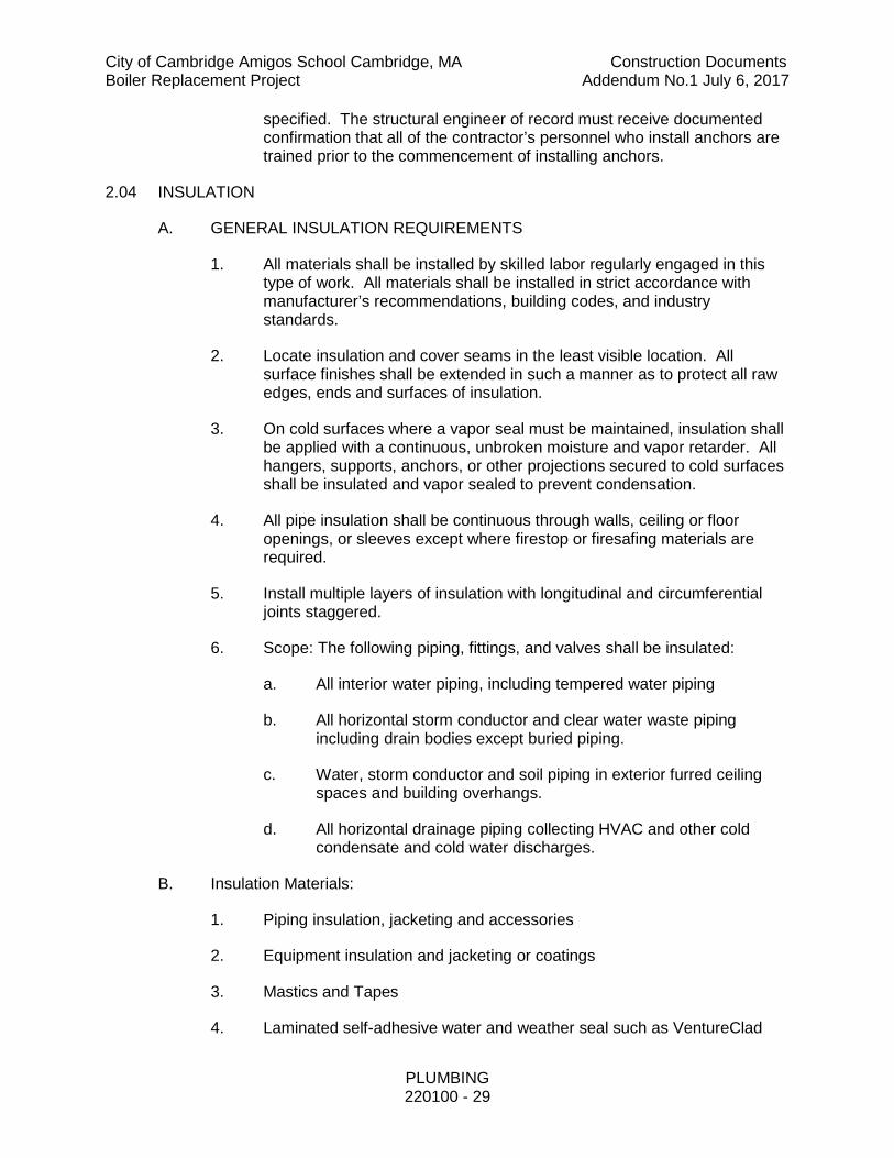
City of Cambridge Amigos School Cambridge, MA Construction Documents Boiler Replacement Project Addendum No.1 July 6, 2017
PLUMBING 220100 - 29
specified. The structural engineer of record must receive documented confirmation that all of the contractor’s personnel who install anchors are trained prior to the commencement of installing anchors.
2.04 INSULATION
A. GENERAL INSULATION REQUIREMENTS
1. All materials shall be installed by skilled labor regularly engaged in this type of work. All materials shall be installed in strict accordance with manufacturer’s recommendations, building codes, and industry standards.
2. Locate insulation and cover seams in the least visible location. All surface finishes shall be extended in such a manner as to protect all raw edges, ends and surfaces of insulation.
3. On cold surfaces where a vapor seal must be maintained, insulation shall be applied with a continuous, unbroken moisture and vapor retarder. All hangers, supports, anchors, or other projections secured to cold surfaces shall be insulated and vapor sealed to prevent condensation.
4. All pipe insulation shall be continuous through walls, ceiling or floor openings, or sleeves except where firestop or firesafing materials are required.
5. Install multiple layers of insulation with longitudinal and circumferential joints staggered.
6. Scope: The following piping, fittings, and valves shall be insulated:
a. All interior water piping, including tempered water piping
b. All horizontal storm conductor and clear water waste piping including drain bodies except buried piping.
c. Water, storm conductor and soil piping in exterior furred ceiling spaces and building overhangs.
d. All horizontal drainage piping collecting HVAC and other cold condensate and cold water discharges.
B. Insulation Materials:
1. Piping insulation, jacketing and accessories
2. Equipment insulation and jacketing or coatings
3. Mastics and Tapes
4. Laminated self-adhesive water and weather seal such as VentureClad
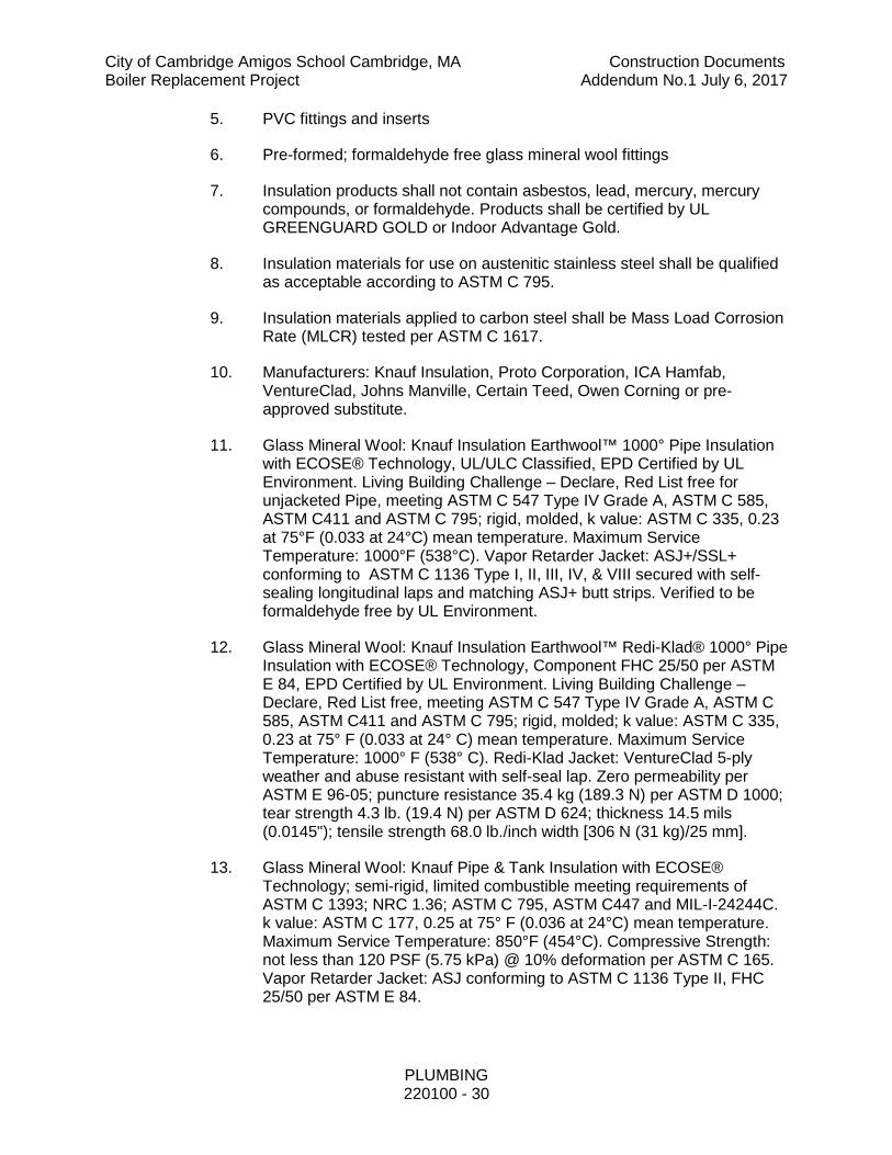
City of Cambridge Amigos School Cambridge, MA Construction Documents Boiler Replacement Project Addendum No.1 July 6, 2017
PLUMBING 220100 - 30
5. PVC fittings and inserts
6. Pre-formed; formaldehyde free glass mineral wool fittings
7. Insulation products shall not contain asbestos, lead, mercury, mercury compounds, or formaldehyde. Products shall be certified by UL GREENGUARD GOLD or Indoor Advantage Gold.
8. Insulation materials for use on austenitic stainless steel shall be qualified as acceptable according to ASTM C 795.
9. Insulation materials applied to carbon steel shall be Mass Load Corrosion Rate (MLCR) tested per ASTM C 1617.
10. Manufacturers: Knauf Insulation, Proto Corporation, ICA Hamfab, VentureClad, Johns Manville, Certain Teed, Owen Corning or pre-approved substitute.
11. Glass Mineral Wool: Knauf Insulation Earthwool™ 1000° Pipe Insulation with ECOSE® Technology, UL/ULC Classified, EPD Certified by UL Environment. Living Building Challenge – Declare, Red List free for unjacketed Pipe, meeting ASTM C 547 Type IV Grade A, ASTM C 585, ASTM C411 and ASTM C 795; rigid, molded, k value: ASTM C 335, 0.23 at 75°F (0.033 at 24°C) mean temperature. Maximum Service Temperature: 1000°F (538°C). Vapor Retarder Jacket: ASJ+/SSL+ conforming to ASTM C 1136 Type I, II, III, IV, & VIII secured with self-sealing longitudinal laps and matching ASJ+ butt strips. Verified to be formaldehyde free by UL Environment.
12. Glass Mineral Wool: Knauf Insulation Earthwool™ Redi-Klad® 1000° Pipe Insulation with ECOSE® Technology, Component FHC 25/50 per ASTM E 84, EPD Certified by UL Environment. Living Building Challenge – Declare, Red List free, meeting ASTM C 547 Type IV Grade A, ASTM C 585, ASTM C411 and ASTM C 795; rigid, molded; k value: ASTM C 335, 0.23 at 75° F (0.033 at 24° C) mean temperature. Maximum Service Temperature: 1000° F (538° C). Redi-Klad Jacket: VentureClad 5-ply weather and abuse resistant with self-seal lap. Zero permeability per ASTM E 96-05; puncture resistance 35.4 kg (189.3 N) per ASTM D 1000; tear strength 4.3 lb. (19.4 N) per ASTM D 624; thickness 14.5 mils (0.0145"); tensile strength 68.0 lb./inch width [306 N (31 kg)/25 mm].
13. Glass Mineral Wool: Knauf Pipe & Tank Insulation with ECOSE® Technology; semi-rigid, limited combustible meeting requirements of ASTM C 1393; NRC 1.36; ASTM C 795, ASTM C447 and MIL-I-24244C. k value: ASTM C 177, 0.25 at 75° F (0.036 at 24°C) mean temperature. Maximum Service Temperature: 850°F (454°C). Compressive Strength: not less than 120 PSF (5.75 kPa) @ 10% deformation per ASTM C 165. Vapor Retarder Jacket: ASJ conforming to ASTM C 1136 Type II, FHC 25/50 per ASTM E 84.

City of Cambridge Amigos School Cambridge, MA Construction Documents Boiler Replacement Project Addendum No.1 July 6, 2017
PLUMBING 220100 - 31
14. Glass Mineral Wool: Knauf KwikFlex™; semi-rigid glass mineral wool blanket in roll form , UL/ULC Classified ASJ and FSK; FHC 25/50 per ASTM E 84 PSK only; meeting requirements of UL 723, ASTM C 1393, ASTM C447 and ASTM C 356. k value: ASTM C 518, 0.24 at 75° F (0.035 at 24°C) mean temperature. Maximum Service Temperature: 850°F (454°C); maximum surface temperature for faced product: 150° F (66° C); maximum thickness @ 850° F: 4 inches (102 mm). Compressive Strength: not less than 25 PSF (1.2 kPa) @ 10% deformation per ASTM C 165. Vapor Retarder Jacket: ASJ, FSK or PSK conforming to ASTM E 96, Procedure A.
15. Fitting Insulation: Insulate using pre-formed PVC fitting covers with glass mineral wool inserts. Alternatively, preformed molded, formaldehyde free glass mineral wool; minimum 50% post-consumer recycled glass content, or mitered glass mineral wool pipe insulation sections. These fittings shall be further protected by field-applied PVC fitting covers, metal fitting covers, or glass fabric and mastic sealed as necessary.
C. All insulation and jacketing/fittings located in air plenums shall be smoke-proof and non-combustible, in compliance with the flame and smoke spread ratings of ASTM E84 (plenum rated).
D. Insulation Thickness:
1. The piping, fittings, and valves shall be insulated per the following (minimum R value of 3.0):
a. Hot water and hot water circulation piping (105oF – 140oF):
1) Pipe size less than 1 ½”: insulation shall be 1" thick (R3.7) and have a thermal conductivity not exceeding 0.27 Btu per inch/hr ۰ ft2 ۰°F. (shall be 1 ½” thick for LEED multifamily Mid-Rise R5.5).
2) Pipe size 1 ½” and greater: insulation shall be 1 ½” thick and have a thermal conductivity not exceeding 0.27 Btu per inch/hr ۰ ft2 ۰°F. (R 5.5)
3) All 140oF hot water and hot water circulation piping shall be insulated with 1 ½” thick insulation that has a thermal conductivity not exceeding 0.27 Btu per inch/hr ۰ ft2 ۰°F. (R 5.5)
b. Cold water piping: insulation shall be 1” thick and have a thermal conductivity not exceeding 0.27 Btu per inch/hr ۰ ft2 ۰°F. (R 3.7)
c. Horizontal storm water conductors and clear water waste piping: insulation shall be 1” thick and have a thermal conductivity not exceeding 0.27 Btu per inch/hr ۰ ft2 ۰°F. (R 3.7). Where the piping turns vertical within 30 feet of the drain or receptor the

City of Cambridge Amigos School Cambridge, MA Construction Documents Boiler Replacement Project Addendum No.1 July 6, 2017
PLUMBING 220100 - 32
vertical portion shall also be insulated down to the first penetration through the floor.
E. Finish
1. Concealed: Vapor barrier jacket on all water piping, except where flexible tubing insulation is used which requires no vapor barrier. Pre-sized glass cloth jacket may be used on hot water piping. Fittings shall be finished with pasted canvas or presized glass cloth jacket.
2. Exposed: Same as concealed except all insulation shall have factory applied 8 ounce canvas finish or pre-sized glass cloth jacket.
3. AJS Fiberglass 24 All Service Jacket.
4. Piping and fittings exposed to the elements or not concealed shall have PVC jacket applied over the factory applied 8 ounce canvas finish or pre-sized glass cloth jacket.
5. Factory Applied Jackets
a. ASJ+/SSL+: All service jacket with Advanced Closure System self-sealing lap. All Service Jacket composed of aluminum foil reinforced with glass scrim bonded to a kraft paper interleaving with an outer film layer leaving no paper exposed.; conforming to ASTM C 1136 Type I, II, III, IV, and VIII; vapor retarder; with a self-sealing adhesive.
b. ASJ: All service jacket. White kraft paper bonded to aluminum foil and reinforced with glass fibers; conforming to ASTM C 1136; vapor retarder.
c. FSK: Foil scrim kraft. Aluminum foil, fiberglass reinforced scrim with kraft backing; conforming to ASTM C 1136 Type 1; vapor retarder.
d. PSK: Poly scrim kraft. Metalized polypropylene, fiberglass reinforced scrim with kraft backing; conforming to ASTM C 1136 Type 1; vapor retarder.
e. Redi-Klad Jacket: VentureClad 5-ply weather and abuse resistant with self-seal lap, Living Building Challenge – Declare, Red List free. Zero permeability per ASTM E 96-05; puncture resistance 35.4 kg (189.3 N) per ASTM D 1000; tear strength 4.3 lb. (19.4 N) per ASTM D 624; thickness 14.5 mils (0.0145"); tensile strength 68.0 lb./inch width [306 N (31 kg)/25 mm].
f. Fire Retardant: products shall contain no polybrominated diphenyl ethers (PBDE) such as Penta-BDE, Octa-BDE or Deca-BDE; whenever available.

City of Cambridge Amigos School Cambridge, MA Construction Documents Boiler Replacement Project Addendum No.1 July 6, 2017
PLUMBING 220100 - 33
6. Field Applied Jackets
a. PVC: Proto Corporation 25/50 or Indoor/Outdoor, UV resistant fittings, jacketing and accessories, white or colored. Fitting cover system consists of pre-molded, high-impact PVC materials with glass mineral wool inserts. Glass mineral wool insert has a thermal conductivity (k value) of 0.26 at 75° F (0.037 at 24°C) mean temperature. Closures: stainless steel tacks, matching PVC tape, or PVC adhesive per manufacturer’s recommendations.
b. Aluminum Jacket: Alloy 3003 or 3105, minimum thickness per ASTM C 1729, smooth, corrugated or stucco embossed with factory-applied moisture barrier. Overlap shall be 2 inch (50 mm) minimum. Jacket shall be banded in place with ½” x 0.20” aluminum strapping fastened with aluminum wing seals.
c. Stainless Steel Jacket: T-304, minimum per ASTM C 1729, smooth, corrugated or embossed with factory-applied moisture barrier. Overlap shall be 2 inch (50 mm) minimum. Jacket shall be banded in place with ⅜” x 0.20” aluminum strapping fastened with stainless steel wing seals.
d. Laminated Self-Adhesive Water and Weather Seals: permanent acrylic self-adhesive system; weather resistant, high puncture and tear resistance; meeting or exceeding requirements of
e. UL 723; and applied in strict accordance with manufacturers’ recommendations.
f. Fire Retardant: products shall contain no polybrominated diphenyl ethers (PBDE) such as Penta-BDE, Octa-BDE or Deca-BDE; whenever available.
F. Application:
1. General
a. All insulation shall be installed in strict accordance with the manufacturer's recommendations and shall be applied by a qualified Insulation subcontractor.
b. Insulation shall not be applied on any apparatus or piping until the apparatus and piping have been thoroughly cleaned, tested and accepted as tight.
2. Piping: Pipe insulation where vapor barrier jacket is required, shall be installed with vapor barrier jackets drawn tight and firmly sealed to assure a positive vaporseal. End joints shall be covered with 4-inch wide butt strips of material identical to vapor barrier jackets, and they shall be drawn tight and securely sealed. The use of staples, bands, etc., to secure insulation where vapor barrier jacket is required will not be

City of Cambridge Amigos School Cambridge, MA Construction Documents Boiler Replacement Project Addendum No.1 July 6, 2017
PLUMBING 220100 - 34
acceptable. Pipe insulation where no vapor barrier is required shall be secured with flare type staples.
3. Fittings and Valves: Cement or moulded insulation on fittings and valve bodies shall be same thickness as adjacent covering and finished neatly to match the adjacent pipe insulation.
G. Hangers
1. Special high density inserts of calcium silicate, cellular glass and other approved material of the same thickness as adjacent insulation shall be installed at points of hanger support. Insulation inserts shall be installed at points of hanger support. Insulation inserts shall be either 180 degrees or 260 degrees and not less than 18" in length. The entire insert shall be covered with a vapor barrier facing of the same appearance and quality as the facing on the adjacent covering.
2. Insulation at hangers, anchors and supports shall be neatly cut and fitted.
3. In Lieu of #2 and #3 above: Snappitz: self locking insulated pipe supports. Insulated Pipe Supports may be provided at hanger, support, and guide locations on pipe requiring insulation. The insert should consist of either Hydrous Calcium Silicate or Polyisocyanurate Foam Insulation (Urethane) encircling the entire circumference of the pipe with a 360° galvanized steel jacket and installed during the installation of the piping system.
H. MASTICS
1. Vapor Retarder Mastics:
a. Knauf Insulation EXPERT Mastics: KI-900 ASJ or KI-905 ASJ+
b. Water Vapor Permeance: ASTM E 96/E 96M, Procedure B, 0.04 perm (0.026 metric perm) at 40 mil dry film thickness.
c. Service Temperature Range: -20°F to 180°F (-29°C to 82.2°C).
d. Color: White
2. Weather Barrier Mastics:
a. Knauf Insulation EXPERT Mastics: KI-700 ASJ or KI-705 ASJ+
b. Water Vapor Permeance: ASTM F 1249, 1.8 perm (1.2 metric perm)
c. Service Temperature: 0°F to 180°F constant (-17.8°C to 82.2°C); -20°F to 200°F intermittent (-29°C to 93°C)

City of Cambridge Amigos School Cambridge, MA Construction Documents Boiler Replacement Project Addendum No.1 July 6, 2017
PLUMBING 220100 - 35
d. Solids: 58% by weight; 50% by volume
e. Color: White
I. TAPES
1. ASJ Tapes:
a. Knauf Insulation EXPERT Tapes: ASJ Tape or ASJ+ Tape
b. Width: 3 inches (75 mm) or 4 inches (101.6 mm)
c. Thickness (Total): 14.3 mil (0.36 mm) – ASJ; 13.3 mil (0.34 mm) – ASJ+
d. Adhesion: >4.8 Lbf / in. (840 N / m)
2. FSK Tape:
a. Knauf Insulation EXPERT Tapes: FSK Tape
b. Width: 3 inch (75 mm) or 4 inch (101.6 mm)
c. Thickness (Total): 13.3 mil (0.34 mm)
d. Adhesion: 6.5 Lbf / in. (1138 N / m)
3. Aluminum Foil Tape:
a. Knauf Insulation EXPERT Tapes: 2 Mil Foil Tape
b. Width: 3 inch (75 mm) or 4 inch (101.6 mm)
c. Thickness (Total): 7.3 mil (0.19 mm)
d. Adhesion: 4.0 Lbf / in. (700 N / m)
2.05 INTERIOR VALVES, FLANGES AND UNIONS
A. General: All systems under this Section shall be provided with valves to permit complete and/or sectional control of the system. They shall be located to permit easy operation, replacement and repair. They shall be installed where shown on the drawings, or as herein specified. They shall be the product of one manufacturer and shall be as manufactured by one of the following companies:
…………Service .....................................................Acceptable Manufacturers.............
Water Valves
Ball Valves: Apollo Watts Watts Nibco

City of Cambridge Amigos School Cambridge, MA Construction Documents Boiler Replacement Project Addendum No.1 July 6, 2017
PLUMBING 220100 - 36
Drain Valves Apollo Watts Nibco
Gas Valves
Shut off Valves Apollo Nibco Watts
Check Valves Circle Valve Dwyer Conval
Pressure Reducing/Regulating Valves
Watts Fisher Mason
Thermally Shut Off Valves Etter Engineering
Inner-Tite Conval
Backflow Preventors Watts Ames Febco
B. All control valves installed more than ten feet above the floor in a mechanical room shall be provided with means for remote operation (chain operator or gear operator with handle extension). All valves installed 36” or more above a ceiling shall be provided with means for remote operation (chain operator or gear operator with handle extension).
C. Water Valves
1. All water valves shall be NSF 61, Appendix G compliant Lead-Free.
2. All valve stems on piping systems that are insulated shall be extended to accommodate thermal insulation.
3. Isolation/shut-off valves up to 2" shall be 2-piece ball valves, all bronze body, full port, Teflon seated stainless steel ball designed for 600 psi water, solder ends, stainless steel stem, lead free.
a. Watts LF B-6081-SS
b. Apollo 77CLF-240
c. Nibco S-685-66-LF.
4. Pressfit valves
a. ½” – 2” : 2 piece, full port, forged body brass or bronze body with chrome plated brass ball, PTFE seats, seals and thrust washer, lead free. Certified to NSF/ANSI 61 annex G by UL. Adjustable packing and a stem O-ring seal. UL listed. Rated to 200psi CWP up to 210F. Designed for use with types K, L and M ASTM B-88 hard copper tubing. Watts LFFFBV-3, Apollo 77WLF-140, Viega 220 series.

City of Cambridge Amigos School Cambridge, MA Construction Documents Boiler Replacement Project Addendum No.1 July 6, 2017
PLUMBING 220100 - 37
5. Isolation/shut-off valves 2 ½” and 3” shall be Full port, two piece flanged ball valves, gear operated with stainless steel ball and stem, lead free. Gear operator shall be provided with the valve or shall be as manufactured by FNW, Flowline Controls, Prism or approved equal. Operator shall be fully enclosed, waterproof housing with set limit stops.
a. Watts G4000-FDA M1-GO or approved equal.
6. Pressure Reducing/ Regulating Valve Constant Outlet Pressure
a. The Pressure Reducing / Regulating Valve shall be a Watts LF-M115 series or approved equal, pilot operated diaphragm valve designed to automatically reduce a fluctuating higher upstream pressure to a constant lower downstream pressure regardless of varying flow rates, and sustain a minimum upstream pressure.
b. The main valve shall be a hydraulically operated, single diaphragm actuated, globe pattern valve. Y-pattern valves shall not be permitted. The valve shall contain a disc and diaphragm assembly that forms a sealed chamber below the valve cover, separating operating pressure from line pressure. The diaphragm shall be constructed of nylon reinforced Buna-N, and shall not seal directly against the valve seat and shall be fully supported by the valve body and cover. Rolling diaphragm construction will not be allowed and there shall ne not pistons operating the main valve or any pilot controls.
c. The main valve body and cover shall be Ductile Iron ASTM A536, and all internal cast components shall be Ductile Iron or CF8M (316) Stainless Steel. All Ductile Iron components, including the body and cover, shall be lined and coated with an NSF 61 Certified Epoxy Coating applied by the electrostatic heat fusion process. All main valve throttling components (valves seat and disc guide) shall be Stainless Steel. The valve body and cover must be machined with a 360-degree locating lip to assure proper alignment.
d. The disc and diaphragm assembly shall contain a BUNA-N synthetic rubber “Quad Seal” that is securely retained on 3-1/2 sides by a disc retainer and disc guide. Diaphragm assemblies utilizing bolts or cap screws for component retention will not be permitted.
e. The exposed portion of the Quad Seal shall contact the valve seat and seal drip-tight. The disc and diaphragm assembly must be guided by two separate bearings, one installed in the valve cover and one concentrically located within the valve seat, to avoid deflection and assure positive disc-to-seat contact. Center guided valves will not

City of Cambridge Amigos School Cambridge, MA Construction Documents Boiler Replacement Project Addendum No.1 July 6, 2017
PLUMBING 220100 - 38
be permitted. All necessary repairs shall be made from the top of the valve while the body remains in line.
f. Pilot control systems shall contain a Flow Clean Strainer, Fixed Orifice Closing Speed, Adjustable Opening Speed Control, Pressure Sustaining Pilot and Pressure Reducing Pilot. All pilot control systems shall be utilized copper tubing and brass fittings regardless of valve size. The adjustment range of the pressure sustaining pilot shall be 20-200 psi and the pressure reducing pilot shall be 30-300 psi.
g. The Pressure Reducing / Regulating Valve shall be a pilot operated diaphragm valve designed to automatically reduce a fluctuating higher upstream pressure to a constant lower downstream pressure regardless of varying flow rates, and sustain a minimum upstream pressure.
h. The main valve shall be a hydraulically operated, single diaphragm actuated, globe pattern valve. Y-pattern valves shall not be permitted. The valve shall contain a disc and diaphragm assembly that forms a sealed chamber below the valve cover, separating operating pressure from line pressure. The diaphragm shall be constructed of nylon reinforced Buna-N, and shall not seal directly against the valve seat and shall be fully supported by the valve body and cover. Rolling diaphragm construction will not be allowed and there shall ne not pistons operating the main valve or any pilot controls.
i. The main valve body and cover shall be Ductile Iron ASTM A536, and all internal cast components shall be Ductile Iron or CF8M (316) Stainless Steel. All Ductile Iron components, including the body and cover, shall be lined and coated with an NSF 61 Certified Epoxy Coating applied by the electrostatic heat fusion process. All main valve throttling components (valves seat and disc guide) shall be Stainless Steel. The valve body and cover must be machined with a 360-degree locating lip to assure proper alignment.
j. The disc and diaphragm assembly shall contain a BUNA-N synthetic rubber “Quad Seal” that is securely retained on 3-1/2 sides by a disc retainer and disc guide. Diaphragm assemblies utilizing bolts or cap screws for component retention will not be permitted.
k. The exposed portion of the Quad Seal shall contact the valve seat and seal drip-tight. The disc and diaphragm assembly must be guided by two separate bearings, one installed in the valve cover and one concentrically located within the valve seat, to avoid deflection and assure

City of Cambridge Amigos School Cambridge, MA Construction Documents Boiler Replacement Project Addendum No.1 July 6, 2017
PLUMBING 220100 - 39
positive disc-to-seat contact. Center guided valves will not be permitted. All necessary repairs shall be made from the top of the valve while the body remains in line.
l. Pilot control systems shall contain a Flow Clean Strainer, Fixed Orifice Closing Speed, Adjustable Opening Speed Control, Pressure Sustaining Pilot and Pressure Reducing Pilot. All pilot control systems shall be utilized copper tubing and brass fittings regardless of valve size. The adjustment range of the pressure sustaining pilot shall be 20-200 psi and the pressure reducing pilot shall be 30-300 psi.
7. Backflow Preventers
a. Shall be NSF 61 compliant.
b. Provide reduced pressure backflow preventors, complete with control valves, repair kit, test kits, pressure gauges and air gap fittings, with drains piped to nearest floor drain. Valves shall be mounted 4'-0" centerline above the floor and properly secured to the wall or floor stand mounted. Devices shall be tested and certified under AWWA Std. No. C506 and FCCCHR of USC manual, Section 10.
1) Size ¼” to 2” shall be Watts 009-QT or approved equal.
2) Sizes 2 ½” – 10” shall be Watts 957-OSY series or approved equal by Ames or Febco.
c. Coordinate with the AHJ for witnessing of the testing of each device and submit final testing reports to the AHJ for their records.
d. Backflow preventor on main domestic water service shall be lead-free and meet AWWA, ASSE or USC approval criteria. Reduced pressure zone device with FDA approved epoxy coated cast iron check valve bodies with bronze seats, FDA approved epoxy coated cast iron relief valve with stainless steel trim, bronze body ball valve test cocks, outside screw and yoke gate valves with resilient wedges and air gap fitting and repair kits shall be supplied for each device.
e. In-line vacuum breakers for continuous pressure shall have bronze body, stainless steel working parts, rubber diaphragm and disc, 3/8" female inlet and outlet connections for in-line continuous pressure applications, polished chrome plated.
f. Backflow preventors with intermediate atmospheric vent shall have all bronze construction with stainless steel internal parts, threaded union connections and built-in strainer, to be

City of Cambridge Amigos School Cambridge, MA Construction Documents Boiler Replacement Project Addendum No.1 July 6, 2017
PLUMBING 220100 - 40
used for ice-maker connections and locations as called for on drawings.
g. Provide flood protection shutdown valve on the supply to the backflow preventer and a water flow switch controller with time delay on the drain discharge line.
1) Watts ACV 113-6RFP control valve with FS99 detector. Provide ACV with 110V power, system shall be wired to the BMS.
D. Gas Valves
1. All gas valves shall have AGA approval, or approval from another testing agency that is acceptable to the Authority Having Jurisdiction, and bear the label of AGA or the other testing agency. Valve shall be UL Listed.
2. Natural gas shutoff valves 2" and smaller shall be bronze ball valves, threaded end,150 psig maximum working pressure, AGA approved and UL Listed. Apollo 77F-100 series or equal by Nibco, or Watts.
3. Over 2" size natural gas shutoff valves shall be lubricated plug cocks, 175 psig maximum working pressure, threaded or flanged ends.
4. Check valves on natural gas piping shall be disc type check valves, brass body, aluminum soft seated disc threaded ends up to and including 2” size. Valves larger than 2” size, ends shall be threaded or flanged.
5. Emergency natural gas shutoff valve cabinet custom steal cabinet with 12” x 12” x 6” with special mounting trim., threaded and lubricated plug cock. Cabinet shall be painted as directed by architect prior to installation. Provide operating wrench for each valve to the owner.
6. Thermally activated gas service shutoff valves (services greater than 4”).
a. Automatically turns off gas supply in the event of fire, preventing explosions and the spreading of fire.
b. When outside temperature reaches 203°F to 212°F (95°C to 100°C) the metal alloy that keeps plug and cartridge together melts and the spring pressure pushes the plug against the gas opening to close it completely. No fire or heat detectors are required to automatically intercept gas flow.
c. CERTIFICATIONS
1) AGA ANSI Z21.15-CGA 9.1-M97 (certain models)
2) CGA ANSI Z21.15-CGA 9.1-M97 (certain models
3) DIN 3586 thermo activated safety device for gas

City of Cambridge Amigos School Cambridge, MA Construction Documents Boiler Replacement Project Addendum No.1 July 6, 2017
PLUMBING 220100 - 41
applications
E. Flanges
1. Flanges shall be companion type, faced and drilled for not less than 150# steam working pressure except flanges on portions of the water service that are subjected to pressures above 150# shall be 300# rated, and all shall be complete with necessary adapter, and shall be of size and material of adjacent piping. ANSI B16.5
F. Unions
1. Malleble Iron Unions shall be suitable for working pressure of not less than 300# and shall be of size and material of adjacent piping. Dart Type with bronze to bronze seats ASME B16.39
2. Wrot Copper Unions ½” through 1”, shall be Lead Free, NSF/ ANSI 61, Annex G, ASME B16.22
3. Bronze Unions 1 ¼” to 3” shall be lead fee, NSF/ANSI 61 Annex G, ASME B16.18.
2.06 PIPE MATERIALS
A. Copper Tubing and Fittings (Type L) -use for all interior water piping.
1. All water piping and connections (fittings) shall be NSF 61 compliant.
2. Tubing to be Type L hard temper conforming to ASTM Specification No. B88 Seamless Copper Water Tube, for assembly with wrought copper or bronze fitting, or with roll grooved fittings. All soldered joints shall be made with ASTM Standard B32 lead free solder.
3. May be used with Victaulic Copper Grooved Fittings.
a. To assure uniformity and compatibility of piping components in grooved end piping systems, all grooved product utilized shall be supplied by the same manufacturer. Grooving tools shall be supplied by the same manufacturer as the grooved components.
b. Couplings: Copper tube dimensions, ASTM A536 ductile iron housing sections, cast with angle-pattern bolt pads to provide system rigidity upon visual metal-to-metal pad contact with no torque requirement, coated with copper-colored enamel; synthetic rubber gasket suitable for water, and bolts and nuts. Victaulic Style 607. Designs that permit spaces or gaps at bolt pads or require a torque per written manufacturers installation instructions not permitted.

City of Cambridge Amigos School Cambridge, MA Construction Documents Boiler Replacement Project Addendum No.1 July 6, 2017
PLUMBING 220100 - 42
c. Flange Adapters: Copper tube dimensions, ASTM A536 ductile iron casting, coated with copper-colored enamel, flat faced, for incorporating flanged components with ANSI Class 125 and 150 bolt-hole patterns to a grooved piping system. Victaulic Style 641.
d. Mechanical T: Victaulic Style 622.
4. May be used with Press Fit type fitting system.
a. ProPress Fittings: Bronze or copper shall conform to the material requirements of ASME B16.18 or ASME B16.22, and the performance requirements of IAPMO PS117, and ICC LC1002.
1) Shall be manufactured by Viega, Nibco or Mueller.
2) ProPress fittings ½-inch thru 4-inch for use with ASTM B88 copper tube type K, L, or M and ½-inch up to include 1-1/4-inch annealed copper tube. ProPress fittings shall have an EPDM sealing element and Smart Connect (SC) feature.
3) 2-1/2-inch thru 4-inch shall have a 420 stainless steel grip ring, PBT separator ring, EPDM sealing element and Smart Connect (SC) feature. Sealing elements shall be verified for the intended use.
4) All ProPress fittings with EPDM sealing element shall conform to NSF 61-pw-G when installed in a potable water system.
b. Pressure ratings:
1) Hot & Cold Potable Water (32°F - 250°F at 200psi)
2) Compressed Air w/less than 25.mg/m oil content (200psi)
3) Rainwater/Greywater (32°F - 250°F at 200psi)
c. Press Fit system shall be installed using the proper tool, actuator, jaws and rings as instructed by the press fitting manufacturer.
d. All fittings must be from the same manufacturer.
e. Installers shall be trained by the manufacturer’s local representative.
5. Mechanically formed Tee Fittings.
a. Mechanically extruded outlets shall be formed by drilling a pilot hole and drawing out the tube surface to form a collar having a height of not less than three (3) times the thickness of the branch

City of Cambridge Amigos School Cambridge, MA Construction Documents Boiler Replacement Project Addendum No.1 July 6, 2017
PLUMBING 220100 - 43
wall. Extruded outlets shall be perpendicular to the axis of the run tube (header).
b. The inner branch tube end shall conform to the shape of the inner curve of the tube. Insertion of the branch tube shall be controlled to assure alignment with specified depth into the collar without extending into the flow stream so as to provide internal reinforcement to the collar.
c. Branches can be formed up to the run tube size as shown in ASTMF 2014. Forming procedures shall be in accordance with the tool manufacturer’s recommendations.
d. All joints shall be brazed using either Copper-Phos Rod (BCup-2), SIL-FOS or ASTM equivalent in accordance with ASME B31.9 2004, paragraph 928.1
6. May be used above ground for soil, waste, vent and storm conductor piping in lieu of cast iron soil pipe and shall be used for indirect waste piping where space is limited or where called for on the drawings, except urinal waste piping shall remain cast iron. Fittings shall be made using lead-free solder or Press Fit as specified above.
B. Black Steel Piping and Fitting use for Natural Gas
1. Black steel pipe shall be Schedule 40 conforming to ASTM Designation A53 (seamless type). Fittings shall be black malleable (threaded or flanged) 150 pounds, conforming to ASA Designation B16.3. Shall be used for interior gas. Gas pipe dropping in concrete block walls shall be factory wrapped with corrosion resistant covering No. X-TRU coat or scotch kote.
2. All gas piping 3" and over and all buried gas piping shall be joined by welded connections, except where detailed otherwise.
3. All natural gas piping systems operating at 14”WC or greater pressure shall be welded connections and flanged valves, regulators, meters, etc.
4. Gas piping that is to be installed in block walls shall be protected by polypropylene pipe covering.
5. May be used with Viega MegaPress G fitting system (1/2” to 2”)
a. Compliance
1) ANSI LC4/CSA 6.32 • CRN #OA14541.6
2) IAPMO LC4 • ABS
3) ICC LC4 • GL

City of Cambridge Amigos School Cambridge, MA Construction Documents Boiler Replacement Project Addendum No.1 July 6, 2017
PLUMBING 220100 - 44
4) LR
5) Uniform Plumbing Code
6) Uniform Mechanical Code
7) International Plumbing Code
8) International Mechanical Code
9) International Fuel Gas Code
10) ASME B31
11) CSA B149.1
b. Fittings are provided with a factory-installed HNBR sealing element, a 304 stainless steel separator ring and a 420 stainless steel grip ring and are CSA LC4 approved for fuel oil and fuel gas installations.
c. Fittings are constructed with the patented Smart Connect feature to identify connections that need to be pressed. Leak testing/pressure testing is still required as specified herein.
2.07 PIPE SLEEVES AND ESCUTCHEONS
A. The Plumbing Contractor, for work under his charge, shall determine the diameter of each individual wall opening or sleeve before ordering, fabrication or installation.
B. Sleeves and inserts shall not be used in any portions of the building where their use would impair the strength or construction features of the building. Elimination of sleeves must be approved by the Architect.
C. Expect where noted otherwise in this paragraph provide chrome-plated brass escutcheons with set screw for exposed piping, in all areas. In mechanical rooms use plain brass or cast iron escutcheons suitable for painting. All escutcheons shall be sized to fit the bare pipe or insulation in a snug and neat manner. All escutcheons shall be equipped with a means of securing the escutcheon to the piping or the covering. They shall be of sufficient size to cover sleeved openings for the pipes and of sufficient depth to cover sleeves projecting above floors or beyond walls. Escutcheons shall be as manufactured by Beaton and Caldwell, Dearborn Brass or Grinnell.
D. Exterior wall sleeve through masonry walls shall be made water tight by the use of Mechanical Link Seal.
E. Pipe sleeves shall be required on all pipes passing through all walls and floors and shall be made of Schedule galvanized 40 pipe or 16 gauge galvanized steel as follows:

City of Cambridge Amigos School Cambridge, MA Construction Documents Boiler Replacement Project Addendum No.1 July 6, 2017
PLUMBING 220100 - 45
1. Sleeves on pipes passing through masonry or concrete construction shall be Schedule 40 galvanized steel pipe.
2. Sleeves passing through masonry partitions shall be 16 gauge galvanized steel unless required otherwise by item 1. above.
3. Sleeves on pipes passing through drywall construction shall be 16 gauge galvanized steel.
4. Sleeves on pipes passing through fire rated drywall partitions shall be 16 gauge galvanized steel.
5. Where cat iron piping passes through a slab on grade the concrete can be poured directly around the piping.
F. Pipe sleeves shall be set as follows:
1. Set sleeves 1 inch above finish floor (6 inches at penthouses and mechanical rooms) and flush on each side of walls, except sleeves through floor occurring in walls and partitions shall terminate flush with finish floor.
2. Sleeves shall be set securely in place before concrete is poured.
2.08 PENETRATION FIRESTOPPING
A. Performance Requirements
1. General: For penetrations through fire-resistance-rated constructions, including both empty openings and openings containing penetrating items, provide through-penetration firestop systems that are produced and installed to resist spread of fire according to requirements indicated, resist passage of smoke and other gases, and maintain original fire-resistance rating of assembly penetrated.
a. Fire-resistance-rated load-bearing walls, including partitions, with fire protection-rated openings.
b. Fire-resistance-rated non-load-bearing walls, including partitions, with fire protection-rated openings.
c. Fire-resistance-rated floor assemblies.
d. Fire-resistance-rated roof assemblies.
2. Rated Systems: Provide penetration firestopping systems with the following ratings determined per ASTM E 814 or UL 1479:
a. F-Rated Systems: Provide through-penetration firestop systems with F-ratings indicated, as determined per ASTM E 814, but not

City of Cambridge Amigos School Cambridge, MA Construction Documents Boiler Replacement Project Addendum No.1 July 6, 2017
PLUMBING 220100 - 46
less than that equaling or exceeding fire-resistance rating of constructions penetrated.
b. T-Rated Systems: For the following conditions, provide through-penetration firestop systems with T-ratings indicated, as well as F-ratings, as determined per ASTM E 814, where systems protect penetrating items exposed to potential contact with adjacent materials in occupiable floor areas:
1) Penetrations located outside wall cavities.
2) Penetrations located outside fire-resistance-rated shaft enclosures.
3) Penetrations into storage areas containing combustible materials.
3. L-Rated Systems: Where through-penetration firestop systems are indicated in smoke barriers, provide through-penetration firestop systems with L-ratings of not more than 3.0 cfm/sq. ft (0.01524cu. m/s x sq. m) at both ambient temperatures and 400 deg F (204 deg C).
4. For through-penetration firestop systems exposed to view, traffic, moisture, and physical damage, provide products that after curing do not deteriorate when exposed to these conditions both during and after construction.
a. For piping penetrations for plumbing systems, provide moisture-resistant through-penetration firestop systems.
b. For floor penetrations with annular spaces exceeding 4 inches (100 mm) in width and exposed to possible loading and traffic, provide firestop systems capable of supporting floor loads involved either by installing floor plates or by other means.
c. For penetrations involving insulated piping, provide through-penetration firestop systems not requiring removal of insulation.
5. For through-penetration firestop systems exposed to view, provide products with flame-spread ratings of less than 25 and smoke-developed ratings of less than 450, as determined per ASTM E 84.
6. Systems and Product Selection:
a. It is the Installing Contractor's undivided responsibility to select proposed systems and products which are appropriate for the types of penetrations, construction systems and the required fire resistance ratings shown on the Drawings and which comply with the requirements of this specification, subject to review by the Architect.

City of Cambridge Amigos School Cambridge, MA Construction Documents Boiler Replacement Project Addendum No.1 July 6, 2017
PLUMBING 220100 - 47
b. Proprietary products and UL designs when indicated on the Drawings are not intended to imply that products and UL designs of the manufacturer are required to the exclusion of equivalent products of other named acceptable manufacturers.
B. Manufacturers
1. Regional Materials: Provide a minimum of 20 percent of building materials (by cost) that are regionally extracted, processed and manufactured materials within a radius of 500 miles.
2. Manufacturers: Subject to compliance with requirements, available manufacturers offering products that may be incorporated into the Work include, but are not limited to, the following:
a. 3MFire Protection Products, Inc., St. Paul, MN 55144
b. Dap Inc., Dayton, Oh 45401
c. HiltiConstruction Chemicals, Inc, Tulsa, OK 74146.
d. Flamesafe - W.R. Grace & Co., Hatfield, PA 19440
e. Johns Manville.
f. Nelson Firestop Products, Tulsa, OK 74145
g. NUCO Industries, Lake Forest, IL 60045.
h. The RectorSeal Corporation, Houston, TX 77023.
i. Specified Technologies Co., Sommerville, NJ 08876.
j. Tremco, Inc.; Cleveland, OH 44104.
k. USG Corporation, Chicago, IL.
C. Penetration Firestopping
1. Provide penetration firestopping that is produced and installed to resist spread of fire according to requirements indicated, resist passage of smoke and other gases, and maintain original fire-resistance rating of construction penetrated. Penetration firestopping systems shall be compatible with one another, with the substrates forming openings, and with penetrating items if any.
2. Penetrations in Fire-Resistance-Rated Walls: Provide penetration firestopping with ratings determined per ASTM E 814 or UL 1479, based on testing at a positive pressure differential of 0.01-inch wg.

City of Cambridge Amigos School Cambridge, MA Construction Documents Boiler Replacement Project Addendum No.1 July 6, 2017
PLUMBING 220100 - 48
a. Fire-resistance-rated walls include fire walls, fire-barrier walls, smoke-barrier walls, and fire partitions.
b. F-Rating: Not less than the fire-resistance rating of constructions penetrated.
3. Penetrations in Horizontal Assemblies: Provide penetration firestopping with ratings determined per ASTM E 814 or UL 1479, based on testing at a positive pressure differential of 0.01-inch wg.
a. Horizontal assemblies include floors, floor/ceiling assemblies, and ceiling membranes of roof/ceiling assemblies.
b. F-Rating: At least 1 hour, but not less than the fire-resistance rating of constructions penetrated.
c. T-Rating: At least 1 hour, but not less than the fire-resistance rating of constructions penetrated except for floor penetrations within the cavity of a wall.
4. Exposed Penetration Firestopping: Provide products with flame-spread and smoke-developed indexes of less than 25 and 450, respectively, as determined per ASTM E 84.
5. VOC Content: Penetration firestopping sealants and sealant primers shall comply with the following limits for VOC content when calculated according to 40 CFR 59, Subpart D (EPA Method 24):
a. Sealants: 250 g/L.
b. Sealant Primers for Nonporous Substrates: 250 g/L.
c. Sealant Primers for Porous Substrates: 775 g/L.
6. Accessories: Provide components for each penetration firestopping system that are needed to install fill materials and to maintain ratings required. Use only those components specified by penetration firestopping manufacturer and approved by qualified testing and inspecting agency for firestopping indicated.
a. Permanent forming/damming/backing materials, including the following:
1) Semirefractory -fiber or slag/rock-mineral wool-insulation.
2) Ceramic fiber.
3) Sealants used in combination with other forming/damming/backing materials to prevent leakage of fill materials in liquid state.

City of Cambridge Amigos School Cambridge, MA Construction Documents Boiler Replacement Project Addendum No.1 July 6, 2017
PLUMBING 220100 - 49
4) Fire-rated form board.
5) Joint Fillers for joint sealants.
b. Temporary forming materials.
c. Substrate primers.
d. Collars.
e. Steel sleeves.
D. Mixing 1. For those products requiring mixing before application, comply with
through-penetration firestop system manufacturer’s written instructions for accurate proportioning of materials, water (if required), type of mixing equipment, selection of mixer speeds mixing containers, mixing time, and other items or procedures needed to produce products of uniform quality with optimum performance characteristics for application indicated.
E. Materials 1. Use only firestop products that have been UL 1479, ASTM E 814
or UL 2079 tested for specific fire-rated construction conditions conforming to construction assembly type, penetrating item type, annular space requirements, and fire-rating involved for each separate instance.
2. Pre-installed firestop devices for use with noncombustible and combustible pipes (closed and open systems), conduit, and/or cable bundles penetrating concrete floors and/or gypsum walls, the following products or equals are acceptable:
3. Cast-In Place Firestop Device (CP 680-P)
4. Add Aerator Adaptor when used in conjunction with aerator system.
5. Tub Box Kit (CP 681) for use with tub installations.
6. Cast-In Place Firestop Device (CP 680-M) for use with noncombustible penetrants.
7. Firestop Speed Sleeve (CP 653) for use with cable penetrations.
8. Firestop Drop-In Device (CFS-DID) for use with noncombustible and combustible penetrants.
9. Hilti Firestop Block (CFS-BL)

City of Cambridge Amigos School Cambridge, MA Construction Documents Boiler Replacement Project Addendum No.1 July 6, 2017
PLUMBING 220100 - 50
10. Sealants, caulking materials, or foams for use with non-combustible items including steel pipe, copper pipe, rigid steel conduit and electrical metallic tubing (EMT), the following products are acceptable:
a. Intumescent Firestop Sealant (FS-ONE MAX) b. Fire Foam (CP 620) c. Flexible Firestop Sealant (CP 606) d. Firestop Silicone Sealant Gun Grade (CFS-S SIL GG) e. \Firestop Silicone Sealant Self Leveling (CFS-S SIL SL)
11. Sealants or caulking materials for use with sheet metal ducts, the
following products are acceptable:
a. Silicone Sealant Gun Grade (CFS-S SIL GG) b. Flexible Firestop Sealant (CP 606) c. Intumescent Firestop Sealant (FS-ONE MAX))
12. Pre-formed mineral wool designed to fit flutes of metal profile deck
and gap between top of wall and metal profile deck; as a backer for spray material.
a. Speed Plugs (CP 777) b. Speed Strips (CP 767)
13. Intumescent sealants, caulking materials for use with combustible
items (penetrants consumed by high heat and flame) including insulated metal pipe, PVC jacketed, flexible cable or cable bundles and plastic pipe, the following products are acceptable:
a. Intumescent Firestop Sealant (FS-ONE MAX))
14. Foams, intumescent sealants, or caulking materials for use with
flexible cable or cable bundles, the following products are acceptable:
a. Intumescent Firestop Sealant (FS-ONE MAX)) b. Fire Foam (CP 620) c. Flexible Firestop Sealant (CP 606) d. Firestop Silicone Sealant Gun Grade (CFS-S SIL GG) e. Firestop Silicone Sealant Self Leveling (CFS-S SIL SL)
15. Non-curing, re-penetrable intumescent putty or foam materials for
use with flexible cable or cable bundles, the following products are acceptable: a. Firestop Putty Stick (CP 618) b. Firestop Plug (CFS-PL)
16. Wall opening protective materials for use with U.L. listed metallic
and specified nonmetallic outlet boxes, the following products are

City of Cambridge Amigos School Cambridge, MA Construction Documents Boiler Replacement Project Addendum No.1 July 6, 2017
PLUMBING 220100 - 51
acceptable:
a. Firestop Putty Pad (CFS-P PA) b. Firestop Putty Pad (CP 617) c. Firestop Box Insert
17. Firestop collar or wrap devices attached to assembly around
combustible plastic pipe (closed and open piping systems), the following products are acceptable:
a. Firestop Collar (CP 643N) b. Firestop Collar (CP 644) c. Wrap Strips (CP 648E/648S)
18. Materials used for large openings and complex penetrations made
to accommodate cable trays and bundles, multiple steel and copper pipes, electrical busways in raceways, the following products are acceptable:
a. Firestop Mortar (CP 637) b. Firestop Block (CFS-BL) c. Fire Foam (CP 620) d. Firestop Board (CP 675T)
19. Non curing, re-penetrable materials used for large size/complex
penetrations made to accommodate cable trays and bundles, multiple steel and copper pipes, electrical busways in raceways, the following products are acceptable:
a. Firestop Block (CFS-BL) b. Firestop Board (CP 675T)
20. Re-penetrable, round cable management devices for use with new
or existing cable bundles penetrating gypsum or masonry walls, the following products are acceptable:
a. Firestop Speed Sleeve (CP 653) with integrated smoke seal
fabric membrane. b. Firestop Sleeve (CFS-SL SK) c. Retrofit Sleeve (CFS-SL RK) for use with existing cable
bundles. d. Gangplate (CFS-SL GP) for use with multiple cable
management devices. e. Gangplate Cap (CFS-SL GP CAP) for use at blank openings
in gangplate for future penetrations
21. For blank openings made in fire-rated wall or floor assemblies, where future penetration of pipes, conduits, or cables is expected, the following products are acceptable:

City of Cambridge Amigos School Cambridge, MA Construction Documents Boiler Replacement Project Addendum No.1 July 6, 2017
PLUMBING 220100 - 52
a. CFS-BL Firestop Block b. CFS-PL Firestop Plug
22. Provide a firestop system with a "F" Rating as determined by UL
1479 or ASTM E814 which is equal to the time rating of construction being penetrated.
23. Provide a firestop system with an Assembly Rating as determined
by UL 2079 which is equal to the time rating of construction joint assembly.
2.09 DOMESTIC WATER HEATERS (NATURAL GAS)
A. Water heaters shall be constructed per ASME standards and bear the ASME stamp.
B. Commercial
1. Water heaters shall be A.O. Smith, Bradford White or RUUD.
2. This specification is based on Bradford White water heaters.
3. Shall be as scheduled on the drawings. Shall be manufactured by A.O. Smith, Bradford White or RUUD. All venting lengths, combustion air lengths, capacities and spacing requirements shall match that of the specified herein.
4. Start Up
a. Start up on the unit will be performed by factory trained and authorized personnel.
2.10 HOT WATER CIRCULATION PUMPS AND CONTROLS
A. Shall be as scheduled on drawings.
2.11 THERMOMETERS
A. Thermometers shall be bi-metal, adjustable angle design.
1. Thermometers for water systems shall be ASME B40.200, direct red reading, 9" vertical scale, 1 degree increments and shall be an aluminum flangeless case:
a. Watts LFTA
b. Wika TI.901
c. Winters TIM-LF Series

City of Cambridge Amigos School Cambridge, MA Construction Documents Boiler Replacement Project Addendum No.1 July 6, 2017
PLUMBING 220100 - 53
2. Pipe insertion thermometers shall have separable sockets of a material suitable for each given installation. Sockets for insulated lines shall have 2-1/2" extension necks.
3. They shall be of the adjustable angle type to permit easy adjustment of the thermometer case, to facilitate reading after installation.
B. Thermometers shall be furnished complete with all necessary sockets, wells, connectors and accessories required for installation suitable for the service in which installed. All thermowells shall be lead free and suitable for drinking water service. Extension necks shall be furnished for insulated piping.
1. Thermometers shall be installed with full port isolation valves to allow their removal and replacement without disruption to the system on which they are connected.
2. Thermometers shall be installed on the system they are serving, in a location that they can be easily read from the floor (without a ladder), and the entire face of the thermometer can be seen squarely.
C. Thermometers shall be furnished with the temperature ranges of 30° to 100°F for cold water, and of 30° to 240°F for hot water systems.
1. Shall be digital thermometer:
a. As manufactured by Weiss, Weksler or Ametek
b. High impact ABS case
c. -50 oF to 300oF
d. ½” LCD digits with wide ambient formula
e. Accuracy: 1% of reading or 1oF, whichever is greater
f. Resolution: 0.1oF between 19.9oF and 199.9oF
g. Calibration: through case potentiometer adjustment
h. Lux rating: 10 Lux (1 foot-candle)
i. Update: 10 seconds
j. Ambient operating temp: -30 oF to 140 oF
k. Ambient temp error: Zero
l. Humidity 100%
m. Sensor: Glass passivated thermistor

City of Cambridge Amigos School Cambridge, MA Construction Documents Boiler Replacement Project Addendum No.1 July 6, 2017
PLUMBING 220100 - 54
n. Stem assembly: Industrial glass in full conformance with federal specification GG-T-321D. Fully interchangeable with industrial glass thermometers.
2. Pipe insertion thermometers shall have separable sockets of a material suitable for each given installation. Sockets for insulated lines shall have 2-1/2" extension necks.
3. They shall be of the adjustable angle type to permit easy adjustment of the thermometer case, to facilitate reading after installation.
2.12 PRESSURE GAUGES
A. Pressure gauges shall be ASME B40.100, liquid filled (suitable for domestic water applications), 304SS case, stainless steel internals, laminated safety glass lens with black embossed figures and graduations on a white dial face. 1% accuracy of scale range. Gauges shall be:
1. WIKA 213.53 DW Series
2. Winters PFQ-LF Series
3. Trerice Co. D80 Series
4. Marshaltown Mfg. 100MM Stainless steel
B. Gauges shall be furnished with snubbers and needle valve shutoffs.
C. Gauges shall be 4" diameter furnished with ranges that will locate the intended pressure at the point of application approximately midpoint on the range scale. Gauges for natural gas, vacuum and similar low pressure systems shall be gauges specifically designed for low pressure applications.

City of Cambridge Amigos School Cambridge, MA Construction Documents Boiler Replacement Project Addendum No.1 July 6, 2017
PLUMBING 220100 - 55
PART 3 – EXECUTION
3.01 COOPERATION AND WORK PROGRESS
A. The Plumbing work shall be carried on under the usual construction conditions, in conjunction with all other work at the site. The Plumbing Subcontractor shall cooperate with the Architect, General Contractor, all other Subcontractors and equipment suppliers working at the site. The Plumbing Subcontractor shall coordinate the work and proceed in a manner so as not to delay the progress of the project.
B. The Plumbing Subcontractor shall coordinate his work with the progress of the building and other Trades so that he will complete his work as soon as conditions permit and such that interruptions of the building functions will be at a minimum. Any overtime hours worked or additional costs incurred due to lack of. or improper coordination with. other Trades or the Owner by the Plumbing Subcontractor, shall be assumed by the Plumbing Subcontractor without any additional cost to the Owner.
C. The Plumbing Subcontractor shall furnish information on all equipment that is furnished under this Section but installed under another Section to the installing Subcontractor as specified herein.
D. The Plumbing Subcontractor shall provide all materials, equipment and workmanship to provide for adequate protection of all electrical equipment during the course of construction of the project. This shall also include protection from moisture and all foreign matter. The Plumbing Subcontractor shall also be responsible for damage which he causes to the work of other Trades, and he shall remedy such injury at his own expense.
E. Waste materials shall be removed promptly from the premises. All material and equipment stored on the premises shall be kept in a neat and orderly fashion. Material or equipment shall not be stored where exposed to the weather. The Plumbing Subcontractor shall be responsible for the security, safekeeping and damages, including acts of vandalism, of all material and equipment stored at the job site.
F. The Plumbing Subcontractor shall be responsible for unloading all equipment and materials delivered to the site. This shall also include all large and heavy items or equipment which require hoisting. Consult with the General Contractor for hoisting/crane requirements. During construction of the building, the Plumbing Subcontractor shall provide additional protection against moisture, dust accumulation and physical damage of the equipment. This shall include furnishing and installing temporary heaters within these units, as approved, to evaporate excessive moisture and ventilate it from the room, as may be required.
G. It shall be the responsibility of the Plumbing Subcontractor to coordinate the delivery of the equipment to the project prior to the time installation of equipment will be required; but he shall also make sure such equipment is not delivered too far in advance of such required installation, to ensure that possible damage and deterioration of such equipment will not occur. Such equipment stored for an

City of Cambridge Amigos School Cambridge, MA Construction Documents Boiler Replacement Project Addendum No.1 July 6, 2017
PLUMBING 220100 - 56
excessively long period of time (as determined in the opinion of the Architect) on the project site prior to installation may be subject to rejection by the Architect.
H. The Plumbing Subcontractor shall erect and maintain, at all times, necessary safeguards for the protection of life and property of the Owner, Workmen, Staff and the Public.
I. Prior to installation, the Plumbing Subcontractor has the responsibility to coordinate the exact mounting arrangement and location of equipment to allow proper space requirements. Particular attention shall be given in the field to group installations. If it is questionable that sufficient space, conflict with the work of other Subcontractors, architectural or structural obstructions will result in an arrangement which will prevent proper access, operation or maintenance of the indicated equipment, the Plumbing Subcontractor shall immediately notify the Contractor and not proceed with this part of the Contract work until definite instructions have been given to him by the Architect.
J. The Plumbing Subcontractor shall not allow any of his equipment or piping foreign to the electrical installation to be installed or pass through any room in which electrical systems or equipment are located, such as electric rooms, electric closets, telephone or data closets. The Plumbing Subcontractor shall immediately remove any such piping or equipment.
K. Piping shall not be installed over any electrical equipment; electrical panels, VFD controllers, disconnects, switches, control panels, fire alarm panels, etc. The locations of all equipment shall be coordinated prior to installation so piping systems will not coincide with the locations of any electrical equipment.
L. The Plumbing Subcontractor shall obtain from the Electrical and HVAC Subcontractors copies of all shop drawing prints showing the ductwork piping and conduit installation as they will be put in place on the project. These drawings shall be thoroughly checked by the Plumbing Subcontractor and the routing of all piping and installation of all valves, etc., and plumbing equipment shall be coordinated with the ductwork and conduit so as to prevent any installation conflict. Such coordination shall be done prior to roughing in piping and equipment.
M. Location of all fixtures shall be verified with the Architect prior to roughing. Refer to details and wall elevations on the Architectural drawings. Mounting heights indicated on these drawings and/or specific dimensional information given to the Plumbing Subcontractor by the Architect shall take precedence over such information indicated on the Plumbing drawings.
N. Refer to all other drawings associated with this project. Any and all equipment which require plumbing services or connections, whether indicated on the Plumbing drawings or not, shall be furnished and installed as directed by the Architect.
O. Refer to the Architectural drawings for areas in which the concrete slab is poured on grade. In these areas a waterproofing membrane will be installed on the grade fill or earth prior to pouring of slab. Plumbing piping shall be installed to avoid the

City of Cambridge Amigos School Cambridge, MA Construction Documents Boiler Replacement Project Addendum No.1 July 6, 2017
PLUMBING 220100 - 57
necessity of penetrating this waterproofing membrane. Penetration of the membrane, if required, shall only be made when specifically allowed by the Architect, and shall be made only at locations directed by the Architect.
3.02 INSTALLATION
A. General
1. Unless specifically noted or indicated otherwise, all equipment and material specified in 22 00 00 of this specification or indicated on the drawings shall be installed under this Contract whether or not specifically itemized herein. This Section covers particular installation methods and requirements peculiar to certain items and classes or material and equipment.
2. The Plumbing Subcontractor shall obtain detailed information from manufacturers of equipment as to proper methods of installation.
3. Access to any and all components requiring servicing, adjustment, calibration, maintenance or periodic replacement shall be provided so that the Owner's operations personnel can freely gain access without removal of any materials other than the access panel or ceiling tile. Access shall be understood to mean free, clear and unobstructed from the floor up to the device and/or component being serviced.
4. The Plumbing Subcontractor shall obtain final roughing dimensions and other information as needed for complete installation of items furnished under other Sections or furnished by the Owner.
5. The Plumbing Subcontractor shall keep fully informed of size, shape and position of openings required for material and equipment provided under this and other Sections. Ensure that openings required for work of this Section are coordinated with work of other Sections. Cutting and patching by others as necessary.
6. The Plumbing Subcontractor shall coordinate the utility service installations with
7. All miscellaneous hardware and support accessories, including support rods, nuts, bolts, screws and other such items, shall be of a galvanized or cadmium plated finish or of another approved rust-inhibiting coating.
8. When CPVC piping systems are installed under this division or under another division of the specifications, this div 22 contractor shall be responsible for insuring that no incompatible products of any kind come in contact with the CPVC piping systems of this or any other trade as a result of the division 22 installation.
a. For example (but not limited to):
1) Cutting oils from pipe fitting/threading

City of Cambridge Amigos School Cambridge, MA Construction Documents Boiler Replacement Project Addendum No.1 July 6, 2017
PLUMBING 220100 - 58
2) Wire insulation/wrap (plasticizers) for romex
3) Incompatible fire stopping systems
4) Duct sealants
5) Spray foam insulation
3.03 MATERIALS AND WORKMANSHIP
A. All materials and equipment shall be new and unused and shall meet requirements of the latest Standards of NEMA, UL, ANSI and ASTM. Equipment shall have components required or recommended by OSHA, applicable NFPA documents and shall be UL listed and labeled.
B. Despite references in the specifications or on the drawings to materials or pieces of equipment by name, make or catalog number, such references shall be interpreted as establishing standards of quality for materials and performance.
C. Finish of materials, components and equipment shall not be less than Industry good practice. When material or equipment is visible or subject to corrosive or atmospheric conditions, the finish shall be as approved by the Architect.
D. Provide proper access to material or equipment that requires inspection, replacement, repair or service. If proper access cannot be provided, confer with the Architect as to the best method of approach to minimize effects of reduced access.
E. All work shall be installed in a neat and workmanlike manner and shall be done in accordance with all Local and State Codes.
F. The Owner will not be responsible for material, equipment or the installation of same before testing and acceptance.
3.04 FIRESTOPPING
A. Examine substrates and conditions, with Installer present, for compliance with requirements for opening configurations, penetrating items, substrates, and other conditions affecting performance.
B. Proceed with installation only after unsatisfactory conditions have been corrected.
C. Preparation
1. Surface Cleaning: Clean out openings immediately before installing through-penetration firestop systems to comply with written recommendations of firestop systems manufacturer and the following requirements: a. Remove from surfaces of openings substrates and from
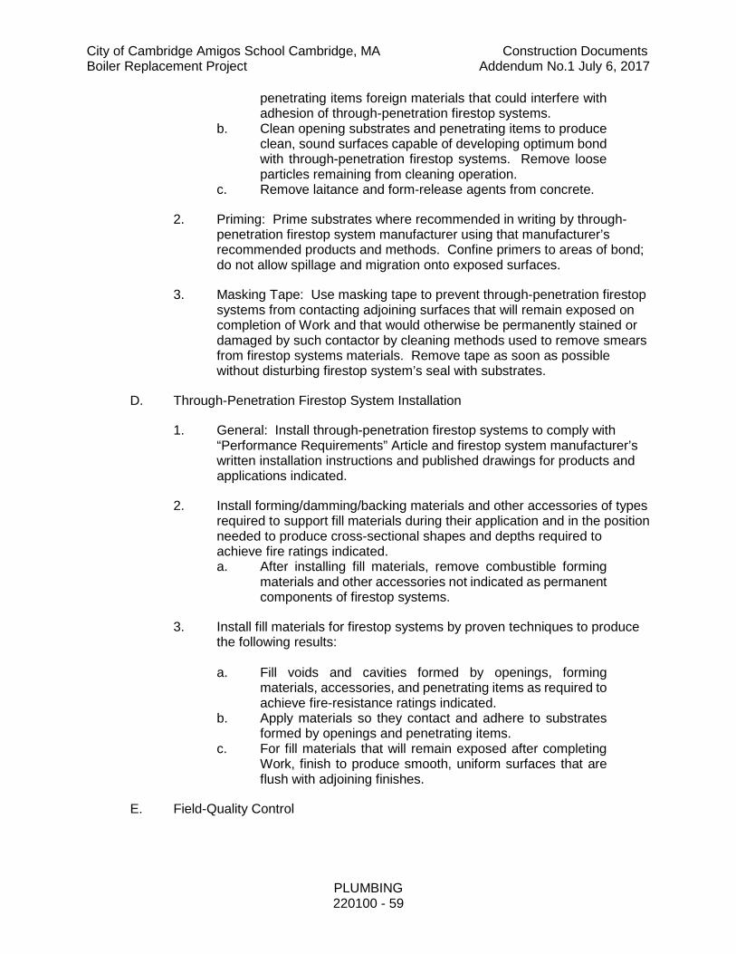
City of Cambridge Amigos School Cambridge, MA Construction Documents Boiler Replacement Project Addendum No.1 July 6, 2017
PLUMBING 220100 - 59
penetrating items foreign materials that could interfere with adhesion of through-penetration firestop systems.
b. Clean opening substrates and penetrating items to produce clean, sound surfaces capable of developing optimum bond with through-penetration firestop systems. Remove loose particles remaining from cleaning operation.
c. Remove laitance and form-release agents from concrete.
2. Priming: Prime substrates where recommended in writing by through-penetration firestop system manufacturer using that manufacturer’s recommended products and methods. Confine primers to areas of bond; do not allow spillage and migration onto exposed surfaces.
3. Masking Tape: Use masking tape to prevent through-penetration firestop systems from contacting adjoining surfaces that will remain exposed on completion of Work and that would otherwise be permanently stained or damaged by such contactor by cleaning methods used to remove smears from firestop systems materials. Remove tape as soon as possible without disturbing firestop system’s seal with substrates.
D. Through-Penetration Firestop System Installation
1. General: Install through-penetration firestop systems to comply with “Performance Requirements” Article and firestop system manufacturer’s written installation instructions and published drawings for products and applications indicated.
2. Install forming/damming/backing materials and other accessories of types required to support fill materials during their application and in the position needed to produce cross-sectional shapes and depths required to achieve fire ratings indicated. a. After installing fill materials, remove combustible forming
materials and other accessories not indicated as permanent components of firestop systems.
3. Install fill materials for firestop systems by proven techniques to produce the following results: a. Fill voids and cavities formed by openings, forming
materials, accessories, and penetrating items as required to achieve fire-resistance ratings indicated.
b. Apply materials so they contact and adhere to substrates formed by openings and penetrating items.
c. For fill materials that will remain exposed after completing Work, finish to produce smooth, uniform surfaces that are flush with adjoining finishes.
E. Field-Quality Control

City of Cambridge Amigos School Cambridge, MA Construction Documents Boiler Replacement Project Addendum No.1 July 6, 2017
PLUMBING 220100 - 60
1. Inspecting Agency: Owner will engage a qualified independent inspecting agency to inspect through-penetration firestop systems and to prepare test reports. a. Inspecting agency will state in each report whether
inspected through-penetration firestop systems comply with or deviate from requirements.
b. Inspection of through-penetration firestopping shall be performed in accordance with ASTM E 2174, “Standard Practice for On-Site Inspection of Installed Fire Stops” or other recognized standard
2. Proceed with enclosing through-penetration firestop systems with other construction only after inspection reports are issued.
3. Where deficiencies are found, repair or replace through-penetration firestop systems so they comply with requirements.
F. Identification
1. Identify through-penetration firestop systems with pressure-sensitive, self-adhesive, preprinted vinyl labels. Attach labels permanently to surfaces of penetrated construction on both sides of each firestop system installation where labels will be visible to anyone seeking to remove penetrating items or firestop systems. Include the following information on labels. a. The words: “Warning-Through-Penetration Firestop
System-Do Not Disturb. Notify Building Management of Any Damage.”
b. Contractor’s name, address, and phone number. c. Through-penetration firestop systems designation of
applicable testing and inspecting agency. d. Date of installation. e. Through-penetration firestop systems manufacturer’s
name. f. Installer’s name.
G. Cleaning And Protection
1. Clean off excess fill materials adjacent to openings as Work progresses by methods and with cleaning materials that are approved in writing by through-penetration firestop system manufacturers and that do not damage materials in which openings occur.
2. Provide final protection and maintain conditions during and after installation that ensure through-penetration firestop systems are without damage or deterioration at time of Substantial Completion. If despite such protection, damage or deterioration occurs, cut out and remove damaged or deteriorated through-penetration firestop systems immediately and install new materials to produce through-penetration firestop systems complying with specified requirements.

City of Cambridge Amigos School Cambridge, MA Construction Documents Boiler Replacement Project Addendum No.1 July 6, 2017
PLUMBING 220100 - 61
H. Firestop System Schedule
1. Install firestop materials for through penetrations in fire rated assemblies in accordance with the following schedule of approved firestop systems:
2. Firestop Systems – Through Penetration Schedule. Provide a schedule of all firestop systems to be used, similar to the following as applies to this specific installation:
Penetrating Item
Concrete Floor/Wall or Block Wall
Gypsum Wall Gypsum Shaft Wall
Blank Opening F-A-0012, F-A-0014
Metal Pipe C-AJ-1149, C-AJ-1291, C-AJ-1226, F-A-1016, F-A-1017
W-L-1054, W-L-1297
W-L-1206, W-L-1380
Plastic Pipe C-AJ-2567, F-A-2053, F-A-2054, F-A-2066
W-L-2128
Cable Bundle C-AJ-3180, C-AJ-3095, F-A-3007, F-A-3033,
W-J-3060
W-L-3065 W-L-3161
Sheet Metal Duct (Rectangular)
C-AJ-7051, C-AJ-7111, C-AJ-7046
W-L-7155
Sheet Metal Duct (Round)
C-AJ-7084, W-J-7022
W-L-7042
Multiple Penetrants C-AJ-8099, F-A-1022, F-A-1023, F-A-8016
W-L-8071, W-L-8079
3.05 CLEANING
A. This Section of the specifications shall include the cleaning of all equipment on a day-to-day basis and final cleaning of all equipment prior to turning building over

City of Cambridge Amigos School Cambridge, MA Construction Documents Boiler Replacement Project Addendum No.1 July 6, 2017
PLUMBING 220100 - 62
to the Owner. All necessary cleaning shall be performed to the satisfaction of the Architect.
3.06 FINAL INSPECTION
A. When all Plumbing work on the project has been completed and is ready for final inspection, such an inspection shall be made. At this time, and in addition to all other requirements in the Contract Documents, the Plumbing Subcontractor, for the work under this Contract, shall demonstrate that the requirements of these specifications have been met to the Architect's satisfaction.
3.07 SUBMITTAL AND SHOP DRAWING CHECKLIST
A. The following is a checklist of job specific items that shall be submitted as Shop Drawings by the Plumbing Sub-Contractor for review and approval by Engineer, Architect and Owner.
B. The shop drawing submittals shall contain but not be limited to the information as stated below AND as stated in each specification section.
Specification Section Product/Category Submittal Requirements Submitted By
Contractor 220000 Plumbing shop
drawings
220000 Plumbing shop drawings
-All gas fired equipment venting and combustion air piping layouts, reviewed by the manufacturer for installation requirements.
220000
Preliminary Shutdown Schedule for Demolition Work
-Schedule of shutdowns coordinated with all trades and approved by the Owner.
220000 Piping -Cut sheets of all items and schedule of materials including joining methods
220000 Valves -Cut sheets of all items and schedule of materials
220000
Equipment: -Water Heaters -Pumps
-Cut sheets of all items and materials, control panels, alarms, operation sequences etc.
220000 Identification -Cut sheets of all items and materials
220000 Hangers and Supports
-Cut sheets of all items and materials
220000 / 078413 Firestopping and Smokestopping
-Cut sheets of all items and materials

City of Cambridge Amigos School Cambridge, MA Construction Documents Boiler Replacement Project Addendum No.1 July 6, 2017
PLUMBING 220100 - 63
Specification Section Product/Category Submittal Requirements Submitted By
Contractor -Schedule of materials and UL listings for each penetration -Engineering Judgments from the manufacturer
220000 Testing Reports
-Testing report including procedure and results for each system or section of each system. Include multiple iterations as performed.
220000 Record As-Built Drawings
-Full set of drawings indicating As-Built conditions.
220000 Operation and Maintenance Manuals (O&M’s)
Complete bound and tabbed binders of all equipment maintenance manuals and recommended maintenance schedule, warranties, letter of completion.

City of Cambridge Amigos School Cambridge, MA Construction Documents Boiler Replacement Project Addendum No.1 July 6, 2017
PLUMBING 220100 - 64
3.08 VERIFYING CONDITIONS
A. The Plumbing Contractor shall verify all conditions and take all measurements in the field as required to insure that all work will fit actual conditions. Field corrections to fabricated work and adjustments to adjacent work where required for the proper installation of the work will be subject to the Architect's approval. Such corrections and adjustments will be permitted only when they will not be detrimental to the appearance and function of all the work.
3.09 SYSTEM SHUTDOWNS (Existing Buildings)
A. The Plumbing Contractor shall coordinate any and all shutdowns of the existing systems to which he is to connect to. Give proper notice to the Owner when making shutdowns, a minimum of fourteen full days are required. Minimize shutdowns on the and Plumbing systems as much as possible. Provide temporary services where required and perform shutdowns and tie ins at a time convenient to the Owner. The Plumbing Contractor shall be responsible for completing the filing of the Owners shutdown notice questionnaire.
B. Perform all required survey and inspection work required by the notice for shutdown.
C. Operation of valves shall be by the Owner.
3.10 TESTING OF PIPING SYSTEMS
A. General
1. All piping systems shall be subjected to testing water, gas or air as noted and shall hold tight at the pressure head stated for the time interval required without adding air or water. While any system is being tested, required head or pressure shall be maintained until all joints are inspected.
2. All tests shall be witnessed by the inspector having jurisdiction and the Architect/Engineer, with 48-hour notice given these authorities.
3. All equipment, material and labor required for testing any of the various systems or any part thereof shall be furnished by this Plumbing Subcontractor including all additional restraints and supports required.
4. All testing reports shall be submitted for record and for review as a part of the submittal process.
5. At no time shall a plastic piping system be pressure tested with air or any other compressed gas.

City of Cambridge Amigos School Cambridge, MA Construction Documents Boiler Replacement Project Addendum No.1 July 6, 2017
PLUMBING 220100 - 65
B. Natural Gas Piping
1. Test pressure shall be a minimum of 10 times the maximum working pressure and never less than 5 psi.
2. Test duration shall be 30 minutes for each 500ft3 of pipe volume tested. The duration of the test shall not be required to exceed 24 hours regardless of volume.
C. Defective Work: If inspection or tests show defects, such defective work or material shall be replaced and inspection and tests shall be repeated. All repairs to piping shall be made with new materials. No caulking of screwed joints or holes will be acceptable.
3.11 SUBCONTRACTOR’S CERTIFICATE OF COMPLETION
A. The following Contractor Certificate of Completion sheet shall be copied on to the Contractor's letterhead, filled out, Singed by the Licensed Permit Holder and sealed by an Authorized Officer of the Corporation then submitted to the Architect for Final Certificate of Occupancy. This is per 780 CMR 107.6.3.

City of Cambridge Amigos School Cambridge, MA Construction Documents Boiler Replacement Project Addendum No.1 July 6, 2017
PLUMBING 220100 - 66
SUBCONTRACTOR’S CERTIFICATE OF COMPLETION
PROJECT
PERMIT NO. TYPE
The undersigned permit holder attests that the scope as installed, is complete and to the best of his knowledge and belief, in substantial accord with the requirements of the Contract Documents and all applicable local, state and federal statutes and regulations.
By: Signature of License holder date
Printed or Typed Name License Number
(seal)
By: Authorized Corporate Officer's Signature date
Printed or Typed Name Title

City of Cambridge Amigos School Cambridge, MA Construction Documents Boiler Replacement Project Addendum No.1 July 6, 2017
PLUMBING 220100 - 67
3.12 DOCUMENTS REQUIRED FOR FINAL AFFIDAVITS
A. These items are required prior to any FINAL AFFIDAVIT being issued to a contractor. All life safety and code issues must be confirmed as completed.
B. The following documents shall be provided on to the Contractor's letterhead, filled out, Singed by the Licensed Permit Holder and sealed by an Authorized Officer of the Corporation then submitted to the Architect for Final Certificate of Occupancy
1. All Code related punch list items have been addressed and signed-off by contractor
2. Plumbing Sub-Contractor Record of Completion
3. Chlorination reports
4. Letter from contractor stating that all fire safing is complete for all floor and wall penetrations.
5. Factory start-up reports and letters certifying that systems are online and operational:
a. Water heaters
6. Pressure/leak testing reports.
7. As-builts provided and certified as accurate by the contractor and the CM to the owners approval.
8. Operation and maintenance manuals as required in the project specifications.
9. Additional letters as required by the Engineer of record, at no additional cost to the project or the owner.
3.13 SITE VISITS AND FIELD REPORTS
A. The engineer shall make visits to the site at intervals as coordinated with the architect and the owner to observe the installation of systems and status of the construction.
B. Site visits shall not be construed as an exhaustive or continuous on-site inspection or to be considered all-inclusive. The observations identified during visits are not intended to indicate that RWS has inspected all the work for conformance to the contract documents and should not be construed as indicating that the construction is complete or correct. The field report list(s) do not contain any hidden defects (not in plain sight) and RWS shall not be responsible for such.

City of Cambridge Amigos School Cambridge, MA Construction Documents Boiler Replacement Project Addendum No.1 July 6, 2017
PLUMBING 220100 - 68
C. RWS reserves the right to re-observe portions of the project and may find additional deficiencies. This is only a cursory observation and does not in any way relieve the General Contractor of their obligation to insure that construction is in accordance with all local and federal codes and the contract documents including plans, specifications and all of the project requirements.
3.14 CORE DRILLING
A. All core drilling up to and including 12” in size required for the installation of the plumbing systems is to be done by the Plumbing Contractor. Contractor is to carry all costs for core drilling. The Construction Manager/ /General Contractor will not be responsible for any circular penetrations up to and including 12” diameter in size required for the proper installation of the plumbing systems. Locate all required openings and prior to coring any, coordinate the opening with the Construction Manager /General Contractor and all other trades. Do not disturb the existing systems. Thoroughly investigate the existing conditions in the vicinity of the required opening prior to coring. The Plumbing Contractor shall be responsible for damages to the building and its systems from the coring operations. Disturbances from coring shall be kept to a minimum.
3.15 PLUMBING CONNECTED EQUIPMENT
A. Furnish and install domestic hot and cold water piping, natural gas piping as required including pipe stands and trim and all final connections to plumbing connected equipment furnished by others. Roughing for this equipment shall be as indicated on the drawings.
B. Furnish and install shutoff valves and unions at each piece of equipment. Obtain exact roughing in dimensions from manufacturers of all service locations before connecting to or roughing for equipment.
C. Furnish and install check valves, strainers and vacuum breakers as required.
D. Sinks and equipment connected to by this Contractor but furnished and set under another section of the Specifications shall be identified on the drawings by “P” number and designated as such. Coordinate casework and sink units with Section 11200.
3.16 NATURAL GAS SYSTEM
A. Connect to new service where indicated with an approved shutoff valve and extend to the required points throughout the buildings. Obtain permits and defray all costs incidental to the interior gas piping. Furnish and install all piping, stop valves and connections to all equipment and outlets requiring gas within the building.
B. A suitable drip or condensate pocket shall be installed at bottom of risers.
C. Gas piping and safety devices shall conform to the requirements of the NFPA Standard No. 54 and shall be subject to inspection and approval of the State Gas Regulatory Board.

City of Cambridge Amigos School Cambridge, MA Construction Documents Boiler Replacement Project Addendum No.1 July 6, 2017
PLUMBING 220100 - 69
D. Provide a gas cock valve at each branch runout from main or riser serving gas outlets.
E. All piping shall be securely fastened separately hung and shall not support any other weight or piping. Piping dropping in concrete block walls shall be factory wrapped for corrosion protection.
F. Gas valves or cocks shall not be concealed and shall be readily accessible for inspection and repair. All welded piping shall conform to the latest requirements of the National Fuel Gas Code.
G. Natural gas piping (exposed, outside the building) shall be painted gray with the paint as listed below. Elevated pressure (14” water column and greater) natural gas piping shall be painted yellow whether it is outside or within the building with the paint as listed below:
1. Benjamin Moore Super Spec HP Epoxy Mastic P45, self priming, high build, impact resistant, interior or exterior application.
H. Immediately adjacent to the point the gas line enters the building, furnish and install a full line size thermally activated automatic shut-off valve inside the building.
I. Purging shall be per NFPA 54 and as follows:
1. Scope:
a. The purging of piping systems shall be in accordance with the provisions of 8.3.1.1 through 8.3.1.4 where the piping system meets either of the following:
1) The design operating gas pressure is greater than 2 psig (14 kPa).
2) The piping being purged contains one or more sections of pipe or tubing greater than 2 in. and exceeding the lengths in NFPA 54 table 8.3.1.1 as follows:
Nominal Pipe Size
Length of Pipe
2 ½” Greater than 50’
3” Greater than 30’
4” Greater than 15’

City of Cambridge Amigos School Cambridge, MA Construction Documents Boiler Replacement Project Addendum No.1 July 6, 2017
PLUMBING 220100 - 70
6” Greater than 10’
8” and larger Any length
3) Where existing gas piping is opened, the section that is opened shall be isolated from the gas supply and the line pressure vented to the exterior per NFPA 54, the residual fuel gas in the piping shall be displaced with an inert gas.
b. Piping Systems Allowed to Be Purged Indoors or Outdoors.
1) The purging of piping systems shall be in accordance with the provisions of 8.3.2.1 where the piping system meets the following:
a) The design operating pressure is 2 psig (14 kPa) or less AND the piping system being purged is constructed entirely from pipe or tubing of 2-in. nominal size or smaller, or larger pipe or tubing with lengths shorter than specified herein before.
2. Purging Procedure
a. The piping system shall be purged in accordance with one or more of the following:
1) The piping shall be purged with fuel gas and shall discharge to the outdoors.
2) The piping shall be purged with fuel gas and shall discharge to the indoors or outdoors through an appliance burner not located in a combustion chamber. Such burner shall be provided with a continuous source of ignition.
3) The piping shall be purged with fuel gas and shall discharge to the indoors or outdoors through a burner that has a continuous source of ignition and that is designed for such purpose.
4) The piping shall be purged with fuel gas that is discharged to the indoors or outdoors, and the point of discharge shall be monitored with a listed combustible gas detector. Purging shall be stopped when fuel gas is detected.
3. Combustible Gas Detector
a. The combustible gas detector used during purging operations shall be listed and shall be calibrated or tested in accordance with the manufacturer’s instructions and recommended schedule.

City of Cambridge Amigos School Cambridge, MA Construction Documents Boiler Replacement Project Addendum No.1 July 6, 2017
PLUMBING 220100 - 71
The combustible gas detector used for pipe discharge monitoring shall indicate the presence of fuel gas.
4. Purging Appliances and Equipment.
a. After the piping system has been placed in operation, appliances and equipment shall be purged before being placed into operation.
J. Placing in Operation
1. Where gas piping containing air is placed in operation, the air in the piping shall first be displaced with an inert gas. The inert gas shall then be displaced with fuel gas in accordance with NFPA 54.
2. Outdoor Discharge of Purged Gases.
a. The open end of a piping system being pressure vented or purged shall discharge directly to an outdoor location. Purging operations shall comply with all of the following requirements:
1) The point of discharge shall be controlled with a shutoff valve.
2) The point of discharge shall be located at least 10 ft (3 m) from sources of ignition, at least 10 ft (3 m) from building openings and at least 25 ft (7.6 m) from mechanical air intake openings.
3) During discharge, the open point of discharge shall be continuously attended and monitored with a combustible gas indicator that complies with
4) Purging operations introducing fuel gas shall be stopped when 90% fuel gas by volume is detected within the pipe.
5) Persons not involved in the purging operations shall be evacuated from all areas within 10 ft (3 m) of the point of discharge.
3. Combustible Gas Indicator.
a. The combustible gas indicator used during purging operations shall be listed and shall be calibrated in accordance with the manufacturer’s instructions and recommended schedule. The combustible gas indicator used for pipe discharge monitoring shall numerically display a volume scale from 0% to 100% with a resolution of not greater than 1% increments.
K. Natural gas fired equipment venting (Massachusetts only)

City of Cambridge Amigos School Cambridge, MA Construction Documents Boiler Replacement Project Addendum No.1 July 6, 2017
PLUMBING 220100 - 72
1. General:
a. The complete installation, alteration, replacement or repair of gas fueled equipment requires that the licensed plumber or gas fitter provide the proper venting of any gas fueled appliance in accordance with the regulations promulgated by the Board, the National Fuel Gas Code, NFPA 54-2002 and ANSI Z223.1-2002. The provisions of these regulations and codes are applicable to licensed plumbers or gas fitters. The licensed plumber or gas fitter is responsible for all aspects of the gas fitting work for which the permit is applied for and issued, including the venting of the flue gases resulting from the operation of the gas appliance installed, altered, replaced or repaired in accordance with all applicable codes and regulations. The licensed plumber or gas fitter must be present for the final inspection of any installation, alteration, replacement or repair of any gas appliance, which includes the proper venting of such equipment. Final inspection will not result in an approval unless all regulations, code provisions and standards are complied with, including those related to the venting of flue gases.
b. The regulations and code provisions for the installation, alteration, repair or replacement of gas fueled equipment, including the venting of the flue gases from that equipment, are enforced as against the licensed plumber or gas fitter to whom the permit for such work is issued, then only a licensed plumber or gas fitter or an appropriately trained person under the control and supervision of a licensed plumber or gas fitter can perform such work, specifically including the venting of gas fueled equipment in accordance with applicable regulations and code provisions.
2. Large Boilers of 400,000 BTU/hr or more:
a. 248 CMR 7.00 of the Massachusetts State Plumbing and Gas Fitting Code addresses Gas Utilization Equipment in Large Boilers (400,000 BTU/hr or more). Because of the size of the venting systems associated with Large Boilers of 400,000 BTU’s or more, it is the Board’s interpretation of its regulations in 248 CMR 7.00 that the vent connectors, vent connector manifolds, breeching, metal or factory built chimneys and or venting system associated with large boilers of 400,000 BTU/hr or greater may be installed by individuals qualified to assemble and construct combustion venting piping or conduits when the following conditions are satisfied;
1) A licensed (Master or Journeyman) Plumber or Gasfitter shall be responsible for and supervise the installation performed by such qualified individuals, and;

City of Cambridge Amigos School Cambridge, MA Construction Documents Boiler Replacement Project Addendum No.1 July 6, 2017
PLUMBING 220100 - 73
2) The supervising licensed (Master or Journeyman) Plumber or Gasfitter has secured a gas fitting permit in compliance with 248 CMR 3.00.
3. Gas Equipment under 400,000 BTU/hr:
a. 248 CMR 5.00 of the Massachusetts State Plumbing and Gas Fitting Code addresses Gas Equipment under 400,000 BTU/hr. It is the Board’s interpretation of its regulations at 248 CMR 5.00 entitled Amendments and Modifications to ANSI Z223.1-NFPA-54, 2002 edition, that the vent connectors, vent connector manifolds, breeching, venting systems or special venting systems of gas appliances and gas equipment that is less than 400,000 BTU/hr may be installed by individuals qualified to assemble and construct combustion venting piping or conduits when the following conditions are satisfied;
b. A licensed (Master or Journeyman) Plumber or Gasfitter shall be responsible for and supervise the installation performed by such qualified individuals, and;
c. The supervising licensed (Master or Journeyman) Plumber or Gasfitter has secured a gas fitting permit in compliance with 248 CMR 3.00.
4. Installation a. Large Boilers of 400,000 BTU/hr or more
1) Shall be installed under division 23 00 00 under a permit pulled for division 22 00 00.
b. Gas Equipment under 400,000 BTU/hr 1) Shall be installed under division 22 00 00 or 23 00 00. 2) For design, installation, and specifications refer to division
22 00 00 or 23 00 00 documents. 5. Startup
a. An authorized representative of the boiler or burner manufacturer shall perform the initial start-up, final adjusting and testing of the burner and controls in the presence of the gas inspector and gas company representative and the licensed plumber responsible for the installation.
b. Provide as many iterations, on different occasions, as needed in order to have a successful startup by the equipment manufacturer in the presence of the gas inspector, the gas company representative and the licensed plumber responsible for the installation.
3.17 PLUMBING SYSTEMS ACCEPTANCE PROCEDURE
A. Performance Testing 1. The Plumbing Subcontractor shall coordinate with other subcontractors,
and work together to demonstrate each system completely to the Owner,

City of Cambridge Amigos School Cambridge, MA Construction Documents Boiler Replacement Project Addendum No.1 July 6, 2017
PLUMBING 220100 - 74
proving that all systems work installed and comply with the design concept, shop drawing and sequence of control. The subcontractor shall submit, by system, a performance test method and format that indicates the system, the point descriptors for all systems, field values, BAS values, occurrence values, manual automatic controls, status values, etc., for approval.
2. The subcontractor shall assist and demonstrate, by witness tests, education programs, inspection, the functioning of the plumbing systems as part of the complete Building Acceptance Procedure. Refer of General Conditions for additional requirements.
3. A separate binder shall be maintained by the subcontractor containing, by system, all punch list items, performance test format and trend logs relative to testing.
4. The subcontractor shall notify the Owner in writing that each system is complete and ready for testing. If it is found that the systems are incomplete, the Plumbing Subcontractor shall reimburse the Owner for additional time, expenses and material required to complete testing of each system.
5. Upon completion of the performance test of each system, the Owner , in writing, shall submit his recommendation regarding acceptance so that beneficial use may be determined.
B. Owner's Acceptance of Test Procedure
1. Submittal data relevant to Performance Characteristics, functions, limits, sequences, interlocks, power fail-restart, and associated parameters and other pertinent information for the operation system and data base shall be forwarded from the Plumbing Subcontractor to the Owner's authorized representative and Engineer's representative.
2. Any deficiency identified during demonstration shall be noted as a punch list item, but progress of demonstration shall not be halted to correct the deficiencies.
3. Problems which occur within approved hardware or software shall be corrected in an appropriate fashion under guarantee. Any such occurrence shall not void previous approval; however, the Plumbing Subcontractor shall be responsible to attend and to remedy such items within reasonable amount of time. Appropriate logs, schedules and reports shall be maintained to reflect these items and their redress.
3.18 OFFSITE WORK AND COORDINATION WITH EXISTING UTILITIES
A. Special attention shall be given to the protection of, and coordination with, existing off-site utilities. Plumbing Subcontractor shall contact the Local Public Works Department and the Gas Company, as well as "DIG-SAFE" to identify and locate these service connections prior to beginning any work.

City of Cambridge Amigos School Cambridge, MA Construction Documents Boiler Replacement Project Addendum No.1 July 6, 2017
PLUMBING 220100 - 75
B. All utility work, both on and off site, shall comply with Local Public Works Department requirements and standards. Submit all equipment, materials and methods to the Public Works Department for approval prior to submitting to the Architect, and prior to purchasing any equipment or materials.
3.19 TERMINATION OF PIPING WITHIN BUILDING
A. Water service piping shall be terminated within the building with a flanged end piece, as detailed on the drawings. The flange shall be set square, level and plumb. Uni-flanges or similar devices are prohibited.
B. Piping passing through foundation walls and floor slabs shall pass through these surfaces square to the surfaces and plumb to the building.
C. Service entrances into the building will be restrained as shown on the details on the drawings, for the developed thrust generated from the water pressure present
END OF SECTION 220100

City of Cambridge Amigos School Cambridge, MA Construction Documents Boiler Replacement Project Addendum No.1 July 6, 2017
CONDENSING BOILERS 235216-1
SECTION 235216 – CONDENSING BOILERS PART 1 - GENERAL 1.01 SUMMARY
A. This Section includes packaged, factory-fabricated and -assembled, gas-fired, fire-tube condensing boilers, trim and accessories for generating hot water.
B. This specification is based on the Aerco Benchmark BMK 2500 but is not intended to be proprietary. Other acceptable manufacturers and models include: 1. Aerco 2. Hydrotherm 3. Lochnivar Crest 4. Fulton Endura 5. Buderus Bosch SB 625 6. Viessmann Manufacturing Co. (US) Inc
C. Alternate boilers must be of equal capacity to the scheduled Aerco boiler. Alternate boilers must be able to operate at full fire with gas pressures available in Cambridge, Ma. 6” WC guaranteed at meter. There is no gas booster on the project. Contractor must engineer and provide a complete gas booster system if more pressure is required at the burner than is available at the gas meter.
1.02 SUBMITTALS A. Product Data: Include performance data, operating characteristics, furnished
specialties, and accessories. 1. Prior to flue vent installation, engineered calculations and drawings must
be submitted to Architect/Engineer to thoroughly demonstrate that size and configuration conform to recommended size, length and footprint for each submitted boiler.
B. Efficiency Curves: At a minimum, submit efficiency curves for 100%, 50% and 7% input firing rates at incoming water temperatures ranging from 80°F to 160°F.
C. Pressure Drop Curve. Submit pressure drop curve for flows ranging from 0 GPM to 375 gpm. 1. If submitted material is different from that of the design basis, boiler
manufacture shall incur all costs associated with reselection of necessary pumps. Possible differences include, but are not limited to, the pump type, pump pad size, electrical characteristics and piping changes.
D. Shop Drawings: For boilers, boiler trim and accessories include: 1. Plans, elevations, sections, details and attachments to other work 2. Wiring Diagrams for power, signal and control wiring
E. Source Quality Control Test Reports: Reports shall be included in submittals. F. Field Quality Control Test Reports: Reports shall be included in submittals.

City of Cambridge Amigos School Cambridge, MA Construction Documents Boiler Replacement Project Addendum No.1 July 6, 2017
CONDENSING BOILERS 235216-2
G. Operation and Maintenance Data: Data to be included in boiler emergency, operation and maintenance manuals.
H. Warranty: Standard warranty specified in this Section I. Other Informational Submittals:
1. ASME Stamp Certification and Report: Submit "A," "S," or "PP" stamp certificate of authorization, as required by authorities having jurisdiction, and document hydrostatic testing of piping external to boiler.
1.03 QUALITY ASSURANCE A. Electrical Components, Devices and Accessories: Boilers must be listed and
labeled as defined in NFPA 70, Article 100, by a testing agency acceptable to authorities having jurisdiction, and marked for intended use.
B. I=B=R Performance Compliance: Condensing boilers must be rated in accordance with applicable federal testing methods and verified by AHRI as capable of achieving the energy efficiency and performance ratings as tested within prescribed tolerances.
C. ASME Compliance: Condensing boilers must be constructed in accordance with ASME Boiler and Pressure Vessel Code, Section IV “Heating Boilers”.
D. ASHRAE/IESNA 90.1 Compliance: Boilers shall have minimum efficiency according to "Gas and Oil Fired Boilers - Minimum Efficiency Requirements."
E. DOE Compliance: Minimum efficiency shall comply with 10 CFR 430, Subpart B, Appendix N, "Uniform Test Method for Measuring the Energy Consumption of Furnaces and Boilers."
F. UL Compliance: Boilers must be tested for compliance with UL 795, "Commercial-Industrial Gas Heating Equipment." Boilers shall be listed and labeled by a testing agency acceptable to authorities having jurisdiction.
G. NOx Emission Standards: When installed and operated in accordance with manufacturer’s instructions, condensing boilers shall comply with the NOx emission standards outlined in South Coast Air Quality Management District (SCAQMD), Rule 1146.1; and the Texas Commission on Environmental Quality (TCEQ), Title 30, Chapter 117, and Rule 117.465.
1.04 COORDINATION A. Coordinate size and location of concrete bases. Cast anchor-bolt inserts into
bases. Concrete, reinforcement and formwork requirements are specified in Division 03.
1.05 WARRANTY A. Standard Warranty: Boilers shall include manufacturer's standard form in which
manufacturer agrees to repair or replace components of boilers that fail in materials or workmanship within specified warranty period. 1. Warranty Period for Fire-Tube Condensing Boilers

City of Cambridge Amigos School Cambridge, MA Construction Documents Boiler Replacement Project Addendum No.1 July 6, 2017
CONDENSING BOILERS 235216-3
a. The pressure vessel/heat exchanger shall carry a 10-year from shipment, non-prorated, limited warranty against any failure due to condensate corrosion, thermal stress, mechanical defects or workmanship.
b. Manufacturer labeled control panels are conditionally warranted against failure for (2) two years from shipment.
c. All other components, with the exception of the igniter and flame detector, are conditionally guaranteed against any failure for 18 months from shipment
PART 2 - PRODUCTS 2.01 CONSTRUCTION
A. Description: Boiler shall be natural gas fired, fully condensing, fire tube design. Power burner shall have full modulation (the minimum firing rate shall not exceed 100,000 BTU/HR input. Boilers that have an input greater than 100,000 BTU/Hr at minimum fire will not be considered) and discharge into a positive pressure vent. Boiler efficiency shall increase with decreasing load (output), while maintaining setpoint. Boiler shall be factory-fabricated, factory-assembled and factory-tested, fire-tube condensing boiler with heat exchanger sealed pressure-tight, built on a steel base, including insulated jacket, flue-gas vent, combustion-air intake connections, water supply, return and condensate drain connections, and controls.
B. Heat Exchanger: The heat exchanger shall be constructed of 439 stainless steel fire tubes and tubesheets, with a one-pass combustion gas flow design. The fire tubes shall be 5/8” OD, with no less than 0.049” wall thickness. The upper and lower stainless steel tubesheet shall be no less than 0.25” thick. The pressure vessel/heat exchanger shall be welded construction. The heat exchanger shall be ASME stamped for a working pressure not less than 160 psig. Access to the tubesheets and heat exchanger shall be available by burner and exhaust manifold removal. Minimum access opening shall be no less than 10-inch diameter.
C. Pressure Vessel: The pressure vessel shall have a maximum water volume of 40 gallons. The boiler water pressure drop shall not exceed 4 psig at 258 gpm. The boiler water connections shall be 4-inch flanged 150-pound, ANSI rated. The pressure vessel shall be constructed of SA53 carbon steel, with a 0.25-inch thick wall and 0.50-inch thick upper head. Inspection openings in the pressure vessel shall be in accordance with ASME Section IV pressure vessel code. The boiler shall be designed so that the thermal efficiency increases as the boiler firing rate decreases.
D. Modulating Air/Fuel Valve and Burner: The boiler burner shall be capable of a 20-to-1 turndown ratio of the firing rate without loss of combustion efficiency or staging of gas valves. The burner shall produce less than 20 ppm of NOx corrected to 3% excess oxygen. The burner shall be metal-fiber mesh covering a stainless steel body with spark ignition and flame rectification. All burner material exposed to the combustion zone shall be of stainless steel construction. There shall be no moving parts within the burner itself. A modulating air/fuel valve shall meter the air and fuel input. The modulating motor must be linked to both the gas valve body and air valve body with a single linkage. The linkage shall not require

City of Cambridge Amigos School Cambridge, MA Construction Documents Boiler Replacement Project Addendum No.1 July 6, 2017
CONDENSING BOILERS 235216-4
any field adjustment. A variable speed cast aluminum pre-mix blower shall be used to ensure the optimum mixing of air and fuel between the air/fuel valve and the burner.
E. Minimum boiler efficiencies shall be as follows at a 20 degree delta-T:
EWT 100% Fire 50% Fire 7% Fire
160 °F 87% 87% 87%
140 °F 88% 88% 88%
120 °F 89% 90% 90.5%
100 °F 93.7% 95% 95%
80 °F 96% 98% 98.6%
F. Exhaust Manifold: The exhaust manifold shall be of corrosion resistant cast
aluminum or 316 stainless steel with an 8-inch diameter flue connection. The exhaust manifold shall have a collecting reservoir and a gravity drain for the elimination of condensation.
G. Blower: The boiler shall include a variable-speed, DC centrifugal fan to operate during the burner firing sequence and pre-purge the combustion chamber. 1. Motors: Blower motors shall comply with requirements specified in
Division 23 Section "Common Motor Requirements for HVAC Equipment." 2. Motor Sizes: Minimum size as indicated. If not indicated, large enough so
driven load will not require a motor to operate in the service factor range above 1.0.
H. Ignition: Ignition shall be via spark ignition with 100 percent main-valve shutoff and electronic flame supervision.
I. The boiler’s manufacturer recommended annual replacement parts shall cost no more than $250 to the end customer.
J. The boiler shall be designed such that the combustion air is drawn from the inside of the boiler enclosure, decoupling it from the combustion air supply and preheating the air to increase efficiency.
K. Enclosure: The sheet metal enclosure shall be fully removable, allowing for easy access during servicing.
2.02 CONTROLS A. The boiler control system shall be segregated into three components: “C-More”
Control Panel, Power Box and Input/Output Connection Box. The entire system shall be Underwriters Laboratories recognized.
B. The control panel shall consist of six individual circuit boards using state-of-the-art surface-mount technology in a single enclosure. These circuit boards shall include:

City of Cambridge Amigos School Cambridge, MA Construction Documents Boiler Replacement Project Addendum No.1 July 6, 2017
CONDENSING BOILERS 235216-5
1. A display board incorporating LED display to indicate temperature and a vacuum fluorescent display module for all message enunciation
2. A CPU board housing all control functions 3. An electric low-water cutoff board with test and manual reset functions 4. A power supply board 5. An ignition /stepper board incorporating flame safeguard control 6. A connector board 7. Each board shall be individually field replaceable. 8. The boiler controls shall be fully integrated with the new Tridium
NiagaraAX 3.6 with BACnet MS/TP protocol & JACE-6E system controller BAS system.
C. The combustion safeguard/flame monitoring system shall use spark ignition and a rectification-type flame sensor.
D. The control panel hardware shall support both RS-232 and RS-485 remote communications.
E. The controls shall annunciate boiler and sensor status and include extensive self-diagnostic capabilities that incorporate a minimum of eight separate status messages and 34 separate fault messages.
F. The control panel shall incorporate three self-governing features designed to enhance operation in modes where it receives an external control signal by eliminating nuisance faults due to over-temperature, improper external signal or loss of external signal. These features include: 1. Setpoint High Limit: Setpoint high limit allows for a selectable maximum
boiler outlet temperature and acts as temperature limiting governor. Setpoint limit is based on a PID function that automatically limits firing rate to maintain outlet temperature within a 0 to 10 degree selectable band from the desired maximum boiler outlet temperature.
2. Setpoint Low Limit: Allow for a selectable minimum operating temperature.
3. Failsafe Mode: Failsafe mode allows the boiler to switch its mode to operate from an internal setpoint if its external control signal is lost, rather than shut off. This is a selectable mode, enabling the control can to shut off the unit upon loss of external signal, if so desired.
G. The boiler control system shall incorporate the following additional features for enhanced external system interface: 1. System start temperature feature 2. Pump delay timer 3. Auxiliary start delay timer 4. Auxiliary temperature sensor 5. Analog output feature to enable simple monitoring of temperature
setpoint, outlet temperature or fire rate

City of Cambridge Amigos School Cambridge, MA Construction Documents Boiler Replacement Project Addendum No.1 July 6, 2017
CONDENSING BOILERS 235216-6
6. Remote interlock circuit 7. Delayed interlock circuit 8. Fault relay for remote fault alarm
H. Each boiler shall include an electric, single-seated combination safety shutoff valve/regulator with proof of closure switch in its gas train. Each boiler shall incorporate dual over-temperature protection with manual reset, in accordance with ASME Section IV and CSD-1.
I. Each boiler shall have an oxygen monitoring system that will measure the oxygen content of the exhaust gasses in real-time. Output of O2 information shall be displayed on the C-More control panel.
J. Each boiler shall have integrated Boiler Sequencing Technology (BST), capable of multi-unit sequencing with lead-lag functionality and parallel operation. The system will incorporate the following capabilities: 1. Efficiently sequence 2-to-8 units on the same system to meet load
requirement. 2. Integrated control and wiring for seamless installation of required isolation
valve. The system shall operate one motorized valve per unit as an element of load sequencing. Valves shall close with decreased load as units turn off, minimum of one must always stay open for recirculation.
3. Automatically rotate lead/lag amongst the units on the chain and monitor run hours per unit and balance load in an effort to equalize unit run hours.
4. Designated master control, used to display and adjust key system parameters.
5. Automatic bump-less transfer of master function to next unit on the chain in case of designated master unit failure; master/slave status should be shown on the individual unit displays.
6. Designated master control, used to display and adjust key system parameters.
K. The controller shall have the ability to vary the firing rate and energy input of each individual boiler throughout its full modulating range to maximize the condensing capability and thermal efficiency output of the entire heating plant. The ACS shall control the boiler outlet header temperature within +2ºF. The controller shall be a PID type controller and uses Ramp Up/Ramp Down control algorithm for accurate temperature control with excellent variable load response. The ACS controller shall provide contact closure for auxiliary equipment such as system pumps and combustion air inlet dampers based upon outdoor air temperature.
L. The ACS shall have the following anti-cycling features: 1. Manual designation of lead boiler and last boiler. 2. Lead boiler rotation at user-specified time interval. 3. Delay the firing/shutting down of boilers when header temperature within
a predefined deadband.
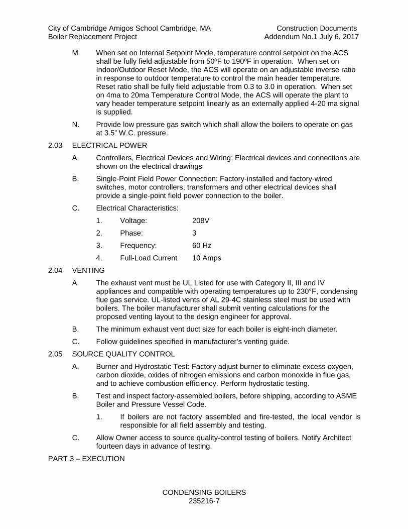
City of Cambridge Amigos School Cambridge, MA Construction Documents Boiler Replacement Project Addendum No.1 July 6, 2017
CONDENSING BOILERS 235216-7
M. When set on Internal Setpoint Mode, temperature control setpoint on the ACS shall be fully field adjustable from 50ºF to 190ºF in operation. When set on Indoor/Outdoor Reset Mode, the ACS will operate on an adjustable inverse ratio in response to outdoor temperature to control the main header temperature. Reset ratio shall be fully field adjustable from 0.3 to 3.0 in operation. When set on 4ma to 20ma Temperature Control Mode, the ACS will operate the plant to vary header temperature setpoint linearly as an externally applied 4-20 ma signal is supplied.
N. Provide low pressure gas switch which shall allow the boilers to operate on gas at 3.5” W.C. pressure.
2.03 ELECTRICAL POWER A. Controllers, Electrical Devices and Wiring: Electrical devices and connections are
shown on the electrical drawings B. Single-Point Field Power Connection: Factory-installed and factory-wired
switches, motor controllers, transformers and other electrical devices shall provide a single-point field power connection to the boiler.
C. Electrical Characteristics: 1. Voltage: 208V 2. Phase: 3 3. Frequency: 60 Hz 4. Full-Load Current 10 Amps
2.04 VENTING A. The exhaust vent must be UL Listed for use with Category II, III and IV
appliances and compatible with operating temperatures up to 230°F, condensing flue gas service. UL-listed vents of AL 29-4C stainless steel must be used with boilers. The boiler manufacturer shall submit venting calculations for the proposed venting layout to the design engineer for approval.
B. The minimum exhaust vent duct size for each boiler is eight-inch diameter. C. Follow guidelines specified in manufacturer’s venting guide.
2.05 SOURCE QUALITY CONTROL A. Burner and Hydrostatic Test: Factory adjust burner to eliminate excess oxygen,
carbon dioxide, oxides of nitrogen emissions and carbon monoxide in flue gas, and to achieve combustion efficiency. Perform hydrostatic testing.
B. Test and inspect factory-assembled boilers, before shipping, according to ASME Boiler and Pressure Vessel Code. 1. If boilers are not factory assembled and fire-tested, the local vendor is
responsible for all field assembly and testing. C. Allow Owner access to source quality-control testing of boilers. Notify Architect
fourteen days in advance of testing. PART 3 – EXECUTION

City of Cambridge Amigos School Cambridge, MA Construction Documents Boiler Replacement Project Addendum No.1 July 6, 2017
CONDENSING BOILERS 235216-8
A. The vent system shall be routed to maintain minimum clearance to combustibles as specified by the manufacturer.
3.01 EXAMINATION A. Before boiler installation examine roughing-in for concrete equipment bases,
anchor-bolt sizes and locations and piping and electrical connections to verify actual locations, sizes and other conditions affecting boiler performance, maintenance and operations. 1. Final boiler locations indicated on Drawings are approximate. Determine
exact locations before roughing-in for piping and electrical connections. B. Examine mechanical spaces for suitable conditions where boilers will be
installed. C. Proceed with installation only after unsatisfactory conditions have been
corrected. 3.02 BOILER INSTALLATION
A. Install boilers level on concrete bases. Concrete base is specified in Division 23 Section "Common Work Results for HVAC," and concrete materials and installation requirements are specified in Division 03.
B. Install gas-fired boilers according to NFPA 54. C. Assemble and install boiler trim. D. Install electrical devices furnished with boiler but not specified to be factory
mounted. E. Install control wiring to field-mounted electrical devices.
3.03 CONNECTIONS A. Piping installation requirements are specified in other Division 23 sections.
Drawings indicate general arrangement of piping, fittings and specialties. B. Install piping adjacent to boiler to permit service and maintenance. C. Install piping from equipment drain connection to nearest floor drain. Piping shall
be at least full size of connection. Provide an isolation valve if required. D. Connect gas piping to boiler gas-train inlet with unions. Piping shall be at least
full size of gas train connection. Provide a reducer if required. E. Connect hot-water piping to supply and return boiler tappings with shutoff valve
and union or flange at each connection. F. Install piping from safety relief valves to nearest floor drain. G. Boiler Venting
1. Install flue venting kit and combustion-air intake. 2. Connect venting full size to boiler connections. [Comply with requirements
in Division 23 Section "Breechings, Chimneys and Stacks."] H. Ground equipment according to Division 26 Section "Grounding and Bonding for
Electrical Systems."

City of Cambridge Amigos School Cambridge, MA Construction Documents Boiler Replacement Project Addendum No.1 July 6, 2017
CONDENSING BOILERS 235216-9
I. Connect wiring according to Division 26 Section "Low-Voltage Electrical Power Conductors and Cables."
J. Set gas low pressure switch to allow boilers to operate at 3.5” W.C. gas pressure 3.04 FIELD QUALITY CONTROL
A. Perform tests and inspections and prepare test reports. 1. Manufacturer's Field Service: Engage a factory-authorized service
representative to inspect components, assemblies and equipment installations, including connections, and to assist in testing.
B. Tests and Inspections 1. Perform installation and startup checks according to manufacturer's
written instructions. 2. Perform hydrostatic test. Repair leaks and retest until no leaks exist. 3. Start units to confirm proper motor rotation and unit operation. Adjust air-
fuel ratio and combustion. 4. Test and adjust controls and safeties. Replace damaged and
malfunctioning controls and equipment. a. Check and adjust initial operating set points and high- and low-
limit safety set points of fuel supply, water level and water temperature.
b. Set field-adjustable switches and circuit-breaker trip ranges as indicated.
C. Remove and replace malfunctioning units and retest as specified above. D. Occupancy Adjustments: When requested within 2 months of date of Substantial
Completion, provide on-site assistance adjusting system to suit actual occupied conditions. Provide up to two visits to Project during other than normal occupancy hours for this purpose.
E. Performance Tests: 1. The boiler manufacturer is expected to provide partial load thermal
efficiency curves. These thermal efficiency curves must include at least three separate curves at various BTU input levels. If these curves are not available, it is the responsibility of the boiler manufacturer to complete the following performance tests: a. Engage a factory-authorized service representative to inspect
component assemblies and equipment installations, including connections, and to conduct performance testing.
b. Boilers shall comply with performance requirements indicated, as determined by field performance tests. Adjust, modify, or replace equipment to comply.
c. Perform field performance tests to determine capacity and efficiency of boilers.
d. Test for full capacity.

City of Cambridge Amigos School Cambridge, MA Construction Documents Boiler Replacement Project Addendum No.1 July 6, 2017
CONDENSING BOILERS 235216-10
e. Test for boiler efficiency at fire 20, 40, 60, 80, 100 percent of full capacity. Determine efficiency at each test point.
f. Repeat tests until results comply with requirements indicated. g. Provide analysis equipment required to determine performance. h. Provide temporary equipment and system modifications
necessary to dissipate the heat produced during tests if building systems are not adequate.
i. Notify Architect in advance of test dates. j. Document test results in a report and submit to Architect.
END OF SECTION 235216

City of Cambridge Amigos School Cambridge, MA Construction Documents Boiler Replacement Project Addendum No.1 July 6, 2017
ATC CONTROL SEQUENCES OF OPERATION AND PRODUCTS 250600-1
SECTION 256000 – ATC CONTROL SEQUENCES OF OPERATION AND PRODUCTS PART 1 – GENERAL 1.01 WORK INCLUDED
A. Furnish and install a complete system of automatic temperature controls. B. The ATC system shall be capable of being integrated into the Cambridge School
Existing Tridium Niagara Network. Component manufacturers shall be equal to Advanced Control Technologies, Reliable, Siemens, or Automatic Logic. Actual integration into the Cambridge School Network shall be made under this contract.
C. The ATC controls system shall be connected to the existing building control system and shall be of the same existing building ATC control system, which is manufactured by Tridium Niagara and serviced by Huntington Controls. 1. ATC contractor shall update existing Amigos School graphics and
add new graphics for new equipment included in this scope of work. Include all sensors, alarms, scheduling, and provide programming as required for sequences and devices.
2. Provide current series controllers compatible with the existing “Vykon JACE-6 system and upgraded to the most current software compatible with the existing BMS. (The existing system is in a closet in Rm-017 adjacent to the kitchen.)
3. The new system shall be able to integrate with the Cambridge School Department’s Niagara Tridium central server. (JCI Metasys, NAE’s or other JCI proprietary products are excluded.)
4. Provide a Tridium NiagaraAX 3.6 with BACnet MS/TP protocol & JACE-6E system controller, include the following minimum requirements: 256 MB RAM, 128Flash, (2) 10/100 Mbps Ethernet ports, (1) non-isolated RS-485 port, (1) RS-232 port, (1) NIDIO port, (2) communication card option slots, embedded software, web user interface, data recovery services with SRAM Niagara Driver, obix driver, and BACnet MS/TP driver. Controller size shall be sufficient to fully meet the requirements of the specification, sequences and I/O schedules.
5. Provide system start-up and commissioning. 6. Provide an on-site training program of three days for the Owner's
staff in the operation and use of the control system. 7. Furnish three instruction manuals covering the function and
operation of the control systems on the project for the use of the Owner's operating personnel. A competent technician shall be provided for instruction purposes.
8. Final system selection shall be approved by owner prior to ordering. 1.02 RELATED SECTIONS

City of Cambridge Amigos School Cambridge, MA Construction Documents Boiler Replacement Project Addendum No.1 July 6, 2017
ATC CONTROL SEQUENCES OF OPERATION AND PRODUCTS 250600-2
A. Examine all drawings and criteria sheets and all other Sections of the Specifications for requirements which affect work under this Section whether such work is specifically mentioned in this Section or not.
1.03 SUBMITTALS A. See Section 230500 and General Conditions for Additional Requirements. B. Product Data: Provide data for materials. C. Prepare and submit sequences and drawings. D. Manufacturer’s Installation Instructions.
1.04 QUALITY ASSURANCE A. All sequences shall be made fully functional. Provide all ancillary components not
specifically called for in this specification (relays, control wiring, etc) necessary for a complete operable system.
PART 2 – PRODUCTS AND SEQUENCES OF OPERATION. 2.02 GENERAL
A. Sequences 1. Hot Water System 2. Hot Water Variable Speed Pump 3. Variable Speed Drives 4. Control Valves 5. Flow Meters 6. Differential Pressure Bypass Valve Arrangement 7. Electric Low Voltage Wiring 8. Optimized Start-Up After Power Failure 9. Coordination with Boiler Manufacturer 10. Boiler Sequencing 11. Unit Heater Controls
2.03 HOT WATER SYSTEM A. Hot Water Loop
1. Provide temperature monitoring sensors at each heat exchanger hot water supply and return piping connection, reporting to the DDC panel. The common hot water supply and return piping temperatures shall be sensed. Hot water reheat pumps shall be activated by the DDC system and shall run continuously.
2.04 HOT WATER VARIABLE SPEED PUMP A. The system controller shall receive an analog signal [4-20mA] from the factory
installed pressure transducer indicating the actual system pressure. When a flow demand is detected (system pressure drops below the start pressure) the VFD/motor shall start and increase speed until the actual system pressure

City of Cambridge Amigos School Cambridge, MA Construction Documents Boiler Replacement Project Addendum No.1 July 6, 2017
ATC CONTROL SEQUENCES OF OPERATION AND PRODUCTS 250600-3
matches the system set-point. As flow demand changes (increases or decreases), the speed of the pump shall be adjusted to maintain the system set-point pressure.
B. If a no flow shut-down is required (periods of zero demand) a bladder type diaphragm tank shall be installed. The tank shall be downstream of the pump. When zero flow is detected by the system controller, the pump shall be switched off. When the system pressure drops to the start pressure, (flow begins after shut-down), the pump shall be switched on, increasing speed to maintain the system set-point pressure. Zero flow conditions shall be detected by the system controller/factory installed pressure transmitter without the use of additional flow switches or motor current sensing devices.
2.05 VARIABLE SPEED DRIVES A. For each VFD, provide the following through the PLC:
1. Motor run feedback points to provide run status in both VFD and bypass mode.
2. Provide mode feedback (VFD and bypass mode). 3. Speed control output signal to VFD. 4. Feedback indicating speed (Hz) and amperage. 5. General alarm from VFD. 6. Start/stop output to VFD. 7. Control ramp up rate. 8. Control ramp down rate. 9. Adjust and set minimum speed.
2.06 CONTROL VALVES A. All valve actuators shall be by Belimo. Valves shall fail open (N.O.), and have
stainless steel stems. 2" and smaller shall be screw 2 1/2" and larger shall be flanged. Pressure rating shall be 250 psig minimum. For modulating control valves maximum pressure drop shall be 7 PSIG at rated flow. Two position control valves shall be line size.
2.07 FLOW METERS A. Flowmeter shall be equal to ONICON Model F-3500 Insertion Electromagnetic
Flow Meter, complete with all installation hardware necessary to enable insertion and removal of the meter without system shutdown. The flow meter shall be hand-insertable up to 400 psi. Materials of construction for wetted metal components shall be 316 SS. The flow meter shall average velocity readings from two sets of diametrically opposed electrodes. Each flow meter shall be individually wet-calibrated against a primary volumetric standard that is accurate to within 0.1% and traceable to NIST*. A certificate of calibration shall be provided with each flow meter. Accuracy shall be within ± 1% of rate from 2-20 ft/s. Overall turndown shall exceed 100:1.
B. Output signals shall be completely isolated and shall consist of the following: (1) analog output; 4-20mA, 0-10V, or 0-5V jumper selectable and (1) scalable dry

City of Cambridge Amigos School Cambridge, MA Construction Documents Boiler Replacement Project Addendum No.1 July 6, 2017
ATC CONTROL SEQUENCES OF OPERATION AND PRODUCTS 250600-4
contact output for totalization, each flow meter shall be covered by the manufacturer’s two-year warranty.
C. Meter shall be installed in accordance with manufacturer’s instructions and shall have required upstream and downstream straight pipe diameters to produce accurate flow.
2.08 DIFFERENTIAL PRESSURE BYPASS VALVE ARRANGMENT A. Provide a differential pressure sensor, reporting to the DDC panel and valve(s) to
maintain constant pressure differential between supply and return piping mains, to automatically bypass water and compensate for pressure fluctuations in the systems. Pressure sensor shall have sensing tips in the supply and return water lines. 1. Hot Water System: One (1) Valve each system
2.09 ELECTRIC LOW VOLTAGE WIRING A. Furnish all labor and material to install the necessary wiring to accomplish the
successful and complete operation of the new automatic system (DDC). B. All electric wiring, wiring connections and all interlocking required for the
installation of the temperature control system, as herein specified, shall be provided by the Contractor, unless specifically shown on the Electrical drawings or called for in the Electrical specifications.
C. Furnish all labor and material to install necessary relays, general purpose enclosures and appurtenances to control designated devices relative to the DDC.
D. All wiring throughout shall be concealed where possible. E. All conduit used shall be EMT, 3/4" minimum size or larger. Conduit sizes shall
be large enough to permit the individual conductors to be readily installed or withdrawn without damage to the conductors or their insulation. Splicing of wires will be permitted only in junction boxes or pull boxes. Conduit shall be rigid up to 12’-0″ AFF in mechanical rooms.
F. Conduit shall never to be relied upon for a fault current and safety ground return conductor.
G. All UL category UUKL portions of the system shall be in conduit. H. All UL category UUKL portions of the system shall be powered from emergency
power. I. The ground system shall not be used as a current carrying conductor except for
faults and noise suppression. The grounding system shall be used to control noise and transients which might affect the operation of the automation system. As such, the ground requirements shall be more than a grounding system used solely for physical protection minimum (Code requirement).
J. In all cases, the bond to ground shall be as short as possible. A ground point shall be de-rated by one (1) point (in order of preference) for each 50’-0″ of conductor run between it and the automation equipment to be grounded. Therefore, a water pipe bond located 10’-0″ away will be preferable to a structural steel bond located 150’-0″ away.

City of Cambridge Amigos School Cambridge, MA Construction Documents Boiler Replacement Project Addendum No.1 July 6, 2017
ATC CONTROL SEQUENCES OF OPERATION AND PRODUCTS 250600-5
K. Set screw connectors shall be galvanized or plated steel. White metal cast type will not be permitted.
L. Flexible conduit shall be used at field devices, i.e., pressure switches, flow switches, temperature devices, etc. Convolutions shall be steel, interlocked continuously. Aluminum will not be permitted. "Liquid-tight" shall be used in wet locations. Flexible connector shall be a minimum of 18" long.
M. Only core drilling is permitted to pierce the floors in the electrical closets and elsewhere. The use of water for drilling shall be controlled by a suitable vacuum system, using proper dams to prevent damage to floors below. The ATC Contractor shall be responsible for providing a suitable sleeve in all core drilled holes as specified herein.
N. All wiring shall be run in EMT as noted below: 1. Sensor to Panel (Block Wall): In Wall Conduit (EMT) 2. Sensor to Panel (Stud Wall): In New Conduit (EMT) 3. Sensor to Panel (Mechanical Room): In New Conduit (EMT) 4. Panel to Front End Workstation: In New Conduit (EMT) 5. Front End: In New Conduit (EMT)
O. Wiring
1. Type THHN solid #18 AWG for control wiring in dry location up to 194°F.
2. Type THWN in wet location up to 167°F (solid #18 AWG). 3. Twisted shielded pair (18 gauge), with PVC cover, Belden #8760 or
approved equal. 4. Conduit is not considered as a shield. 5. All wiring associated with the control signals to the smoke damper
control/sequence must be in approved conduit. 6. All signal wiring to all field devices shall be run with no splices, separately
from any wiring having voltage greater than 30 volts. P. The Contractor shall install all shielded cable and ground systems in accordance
with Division 23. The installation of ground loops shall not affect any sensing or control circuits.
Q. All devices and equipment shall be mounted in minimum NEMA 1 enclosures. R. In addition to the requirements specified above, all communication wiring cables
shall include a minimum of (1) individually 100% shielded pair ([2] conductors) as unused spare conductors. Where the number of conductors and specific cable specified above for each type of communication wiring will not meet this requirement for spare conductors, Contractor shall provide approved equivalent product of Belden or other manufacturer with the necessary number of conductors and which meets the requirements specified above.
S. Low Voltage Control Wiring (30 VAC or Less) 1. Low voltage control wiring shall be minimum 16 gauge, or heavier if
required, twisted pair, 100% shielded with PVC cover Belden #9316 or

City of Cambridge Amigos School Cambridge, MA Construction Documents Boiler Replacement Project Addendum No.1 July 6, 2017
ATC CONTROL SEQUENCES OF OPERATION AND PRODUCTS 250600-6
approved equivalent product of other manufacturers run in conduit with no splices, separate from any wiring above 30 volts.
T. Coordination of Interfacing/Interlocking 1. The Contractor shall be responsible for coordinating all required
interface/interlocking software, software logic, sequencing and wiring necessary to provide a fully automated and fully functional operable system to meet or exceed the intent of the Design Engineer’s Sequence of Operation. Coordination may include but not limited to the following at no additional cost to the Owner. Variable frequency drive (VFD) interlocking and wiring logic including software, relays factory/field installed wiring and/or VFD drive modifications. This would include coordination of miscellaneous points as specified under the point list in this specification.
2.10 OPTIMIZED START-UP AFTER POWER FAILURE A. The ATC Contractor shall start systems and equipment in a staggered manner
after a power failure such that systems and equipment do not start all at once and overload electrical service nor create an excess negative or positive pressure in the building. Provide a 5 second (adj.) delay between start-up of each system.
B. All equipment - any piece of equipment or system that is stopped for any reason other than loss of normal or emergency power must be alarmed and may only reset manually via the BAS. Power failure shall be as sensed by the undercurrent relays and normal/emergency power relays at the electrical automatic transfer switches.
2.11 COORDINATON WITH BOILER MANUFACTURER A. Obtain boiler manufacturer's wiring diagrams for any components to be field
mounted. Coordinate with boiler manufacturer to determine which sensors are provided loose with the boiler for field mounting and which must be provided by ATC. Field wiring shall include but not be limited to outdoor air sensor input; boiler isolation valve open and close; temperature sensor mounted in supply header from boiler; combustion air damper interlock with boiler; pump sequencing with boiler.
B. Existing 240 VAC operator on existing to remain combustion air damper shall be replaced with 115V operator.
2.12 BOILER SEQUENCING A. These sequences are based on AERCO's BST controls. If an alternate boiler is
submitted all sequences listed below shall be provided whether by the boiler manufacturers on board controls or by ATC. In any case, all sequences must be provided under this contract - no additional costs will be permitted because wiring or some other point of coordination "fell through the cracks".
B. Heating System operation will be controlled by an outdoor air sensor which shall be shielded and located on the North side of the building. When the outside air temperature falls below the system enable point the Heating system shall be enabled. When the outside air temperature rises above the set point or the

City of Cambridge Amigos School Cambridge, MA Construction Documents Boiler Replacement Project Addendum No.1 July 6, 2017
ATC CONTROL SEQUENCES OF OPERATION AND PRODUCTS 250600-7
enable is "off", the heating system will be disabled. Provide adequate differential around enable set-point to prevent short cycling.
C. HWS Set points shall be adjustable from 90 degrees to 180 degrees, enable temperatures shall be adjustable from -20 to 70 degrees.
D. The heating loop temperature at initial startup shall be 100 degrees when outdoor air temperature is 60 degrees or higher and shall modulate on a straight-line ratio such that when the outdoor air temperature is 20 degrees or lower the heating loop temperature shall be 140 degrees.
E. At initial Heating System start up when outdoor air temperature falls below set-point and system is enabled the lead boiler isolation valve shall modulate to 100% open, the lead pump shall start. Boiler will initiate start procedure and once flame is proven burners shall modulate to maintain heating loop temperature set-point.
F. Each VFD shall modulate to maintain system differential pressure as outlined in variable pumping sequences.
G. Whenever any Boiler Start circuit is energized, the Outdoor air damper shall open. If no boiler start circuit is energized outdoor air damper shall be closed.
H. Whenever lead boiler is at 45% firing rate and is unable to maintain loop temperature set point, the second boiler shall be activated, slowly opening modulating valve and initiating boiler startup procedure and once flame is proven, modulate burner in series with lead boiler to maintain loop set point.
I. The inactive boiler shall have associated control valve closed preventing flow. J. As firing rate reduces to 40% of full capacity firing rate (adjustable) one boiler
shall shut down. After manufacturer's recommended delay (to dissipate heat) the boiler's motorized isolation valve shall slowly modulate closed. Allow 15 minutes’ minimum (adjustable) between second boiler starting and stopping.
K. Below 60F when there is no call for heat both boiler isolation valves shall open. L. Provide night setback schedule adjustable by user. M. Provide outdoor reset controls, schedule to be adjustable by user. See above for
set-points and reset range. Outdoor air sensor shall be shielded and located on the building's North wall.
N. Which boiler is lead shall be alternated on a weekly basis (schedule to be adjustable by user).
2.13 UNIT HEATER CONTROLS A. Thermostat shall cycle unit heater fan as required to maintain set-point of 50F
(adjustable).