vertical pipe jacket example - peesi.com
TRANSCRIPT
PRESSURE EQUIPMENT ENGINEERING SERVICES, INC. 402 WILD PEACH PLACE
MISSOURI CITY, TX - 77459 TEL. : (281)-261-4628 FAX : (281)-261-4629
E-Mail: [email protected]
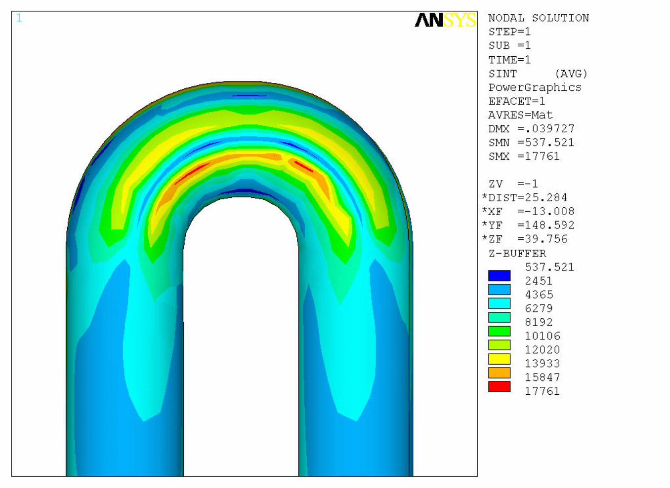
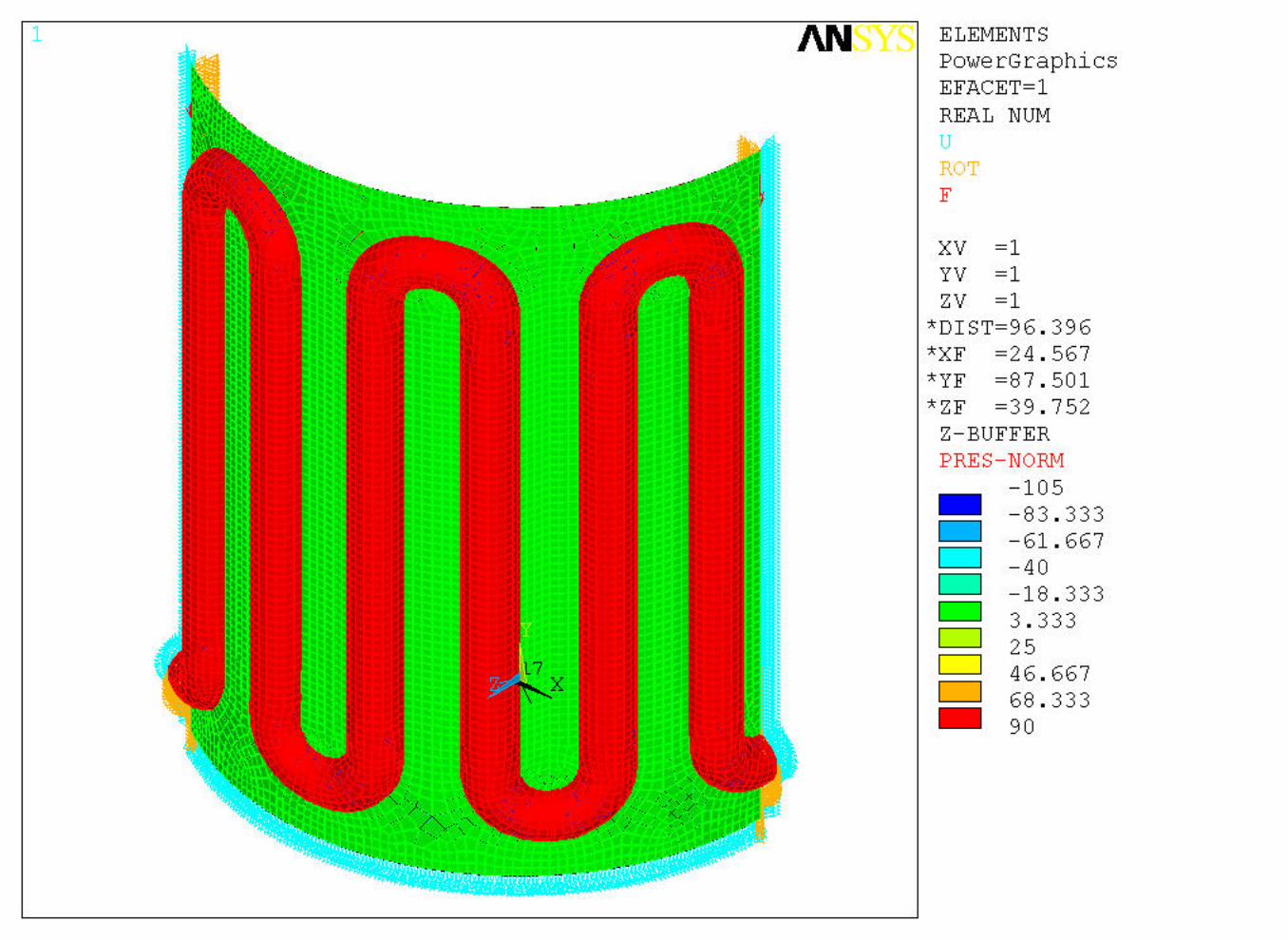
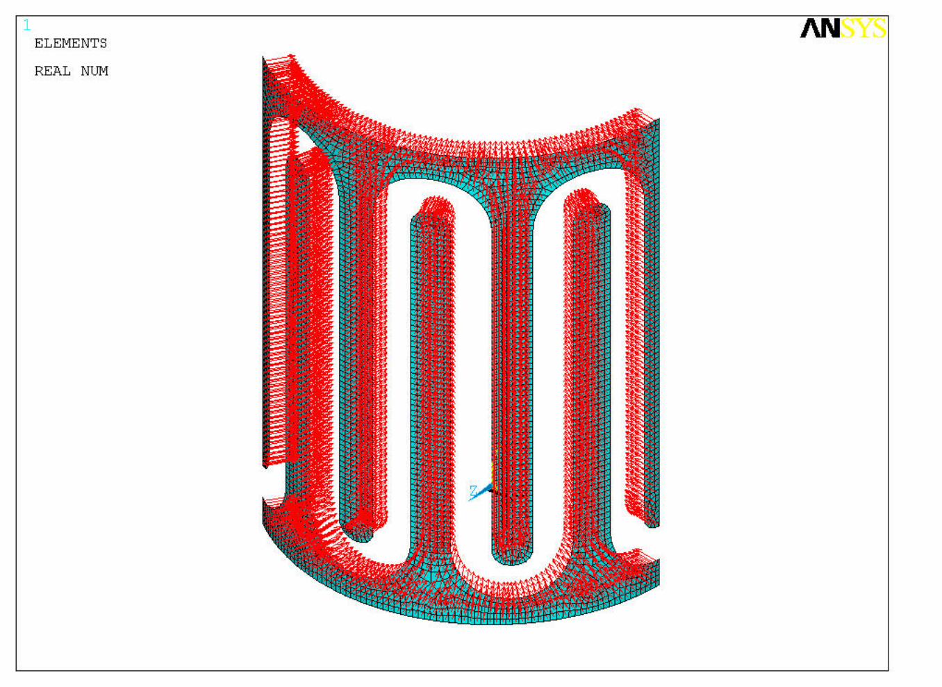
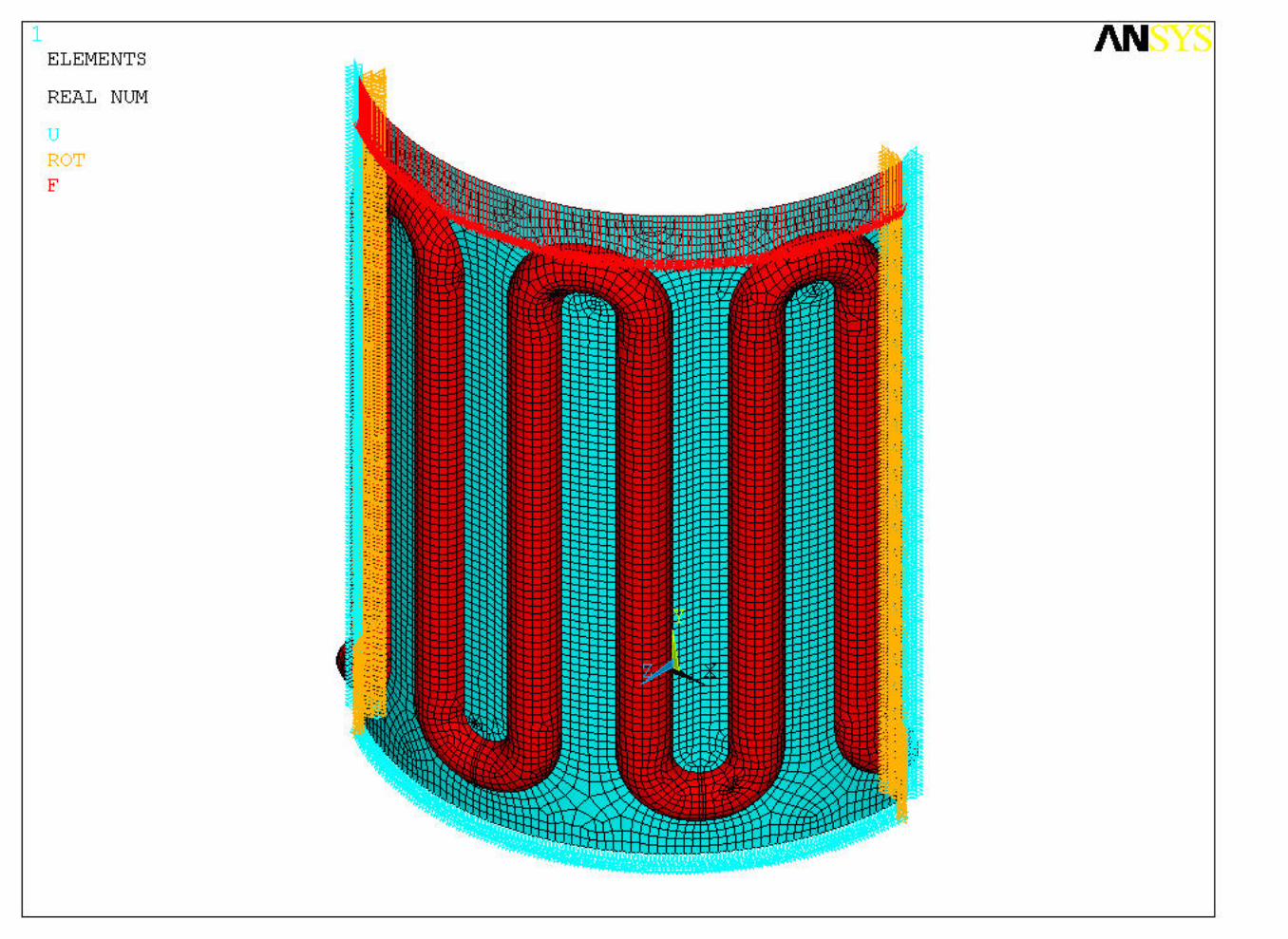
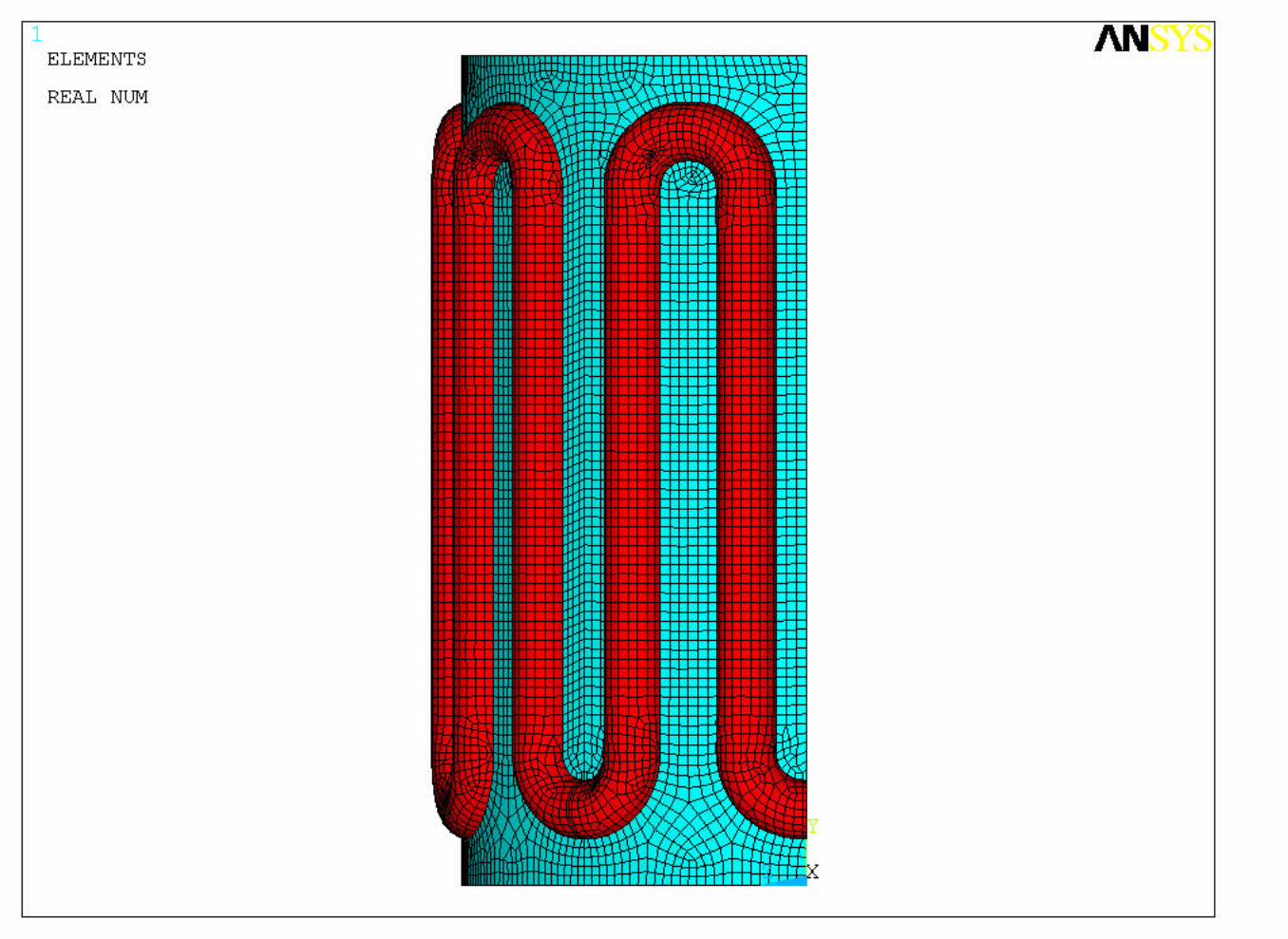
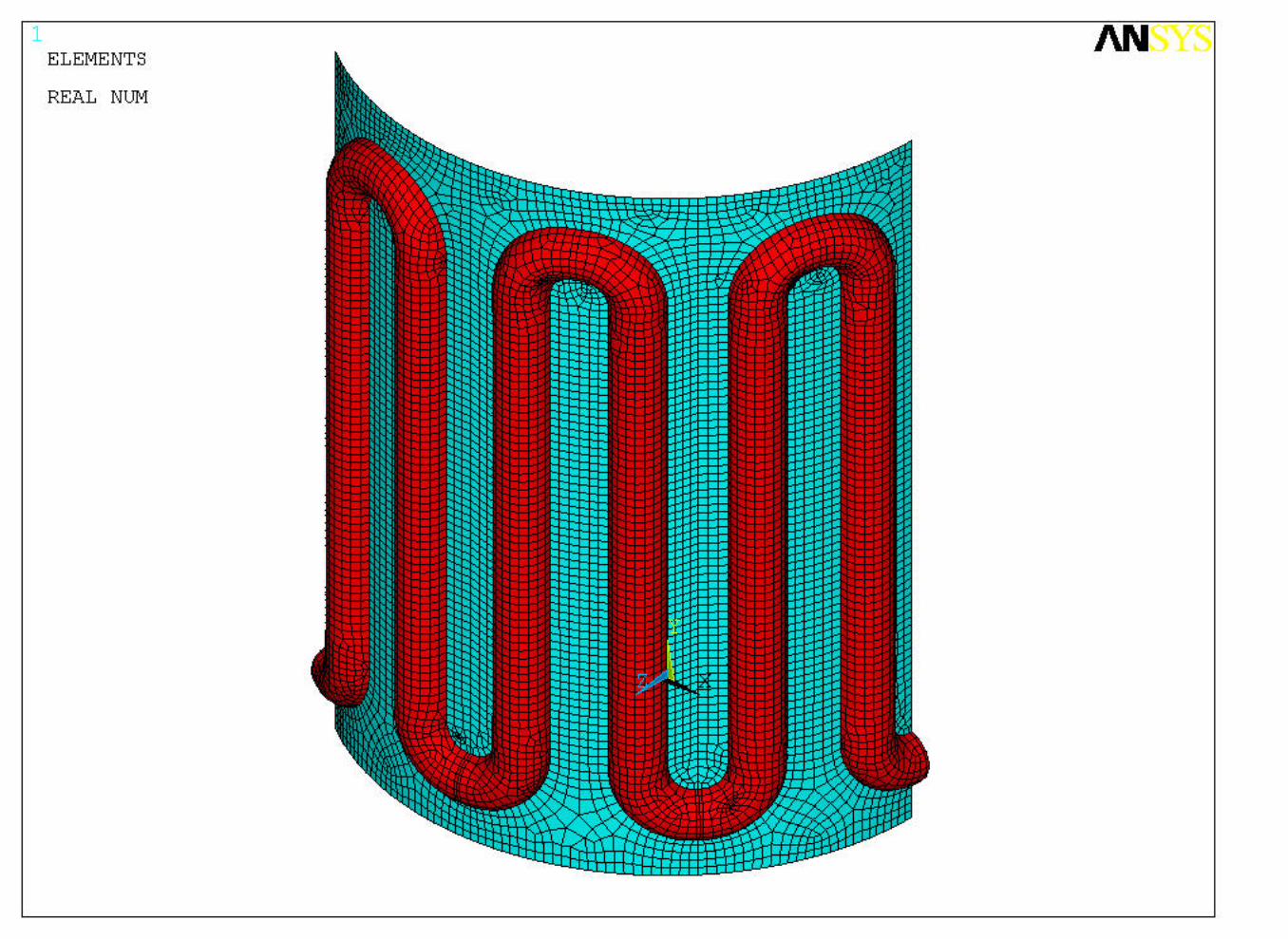
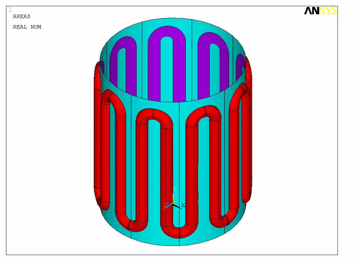
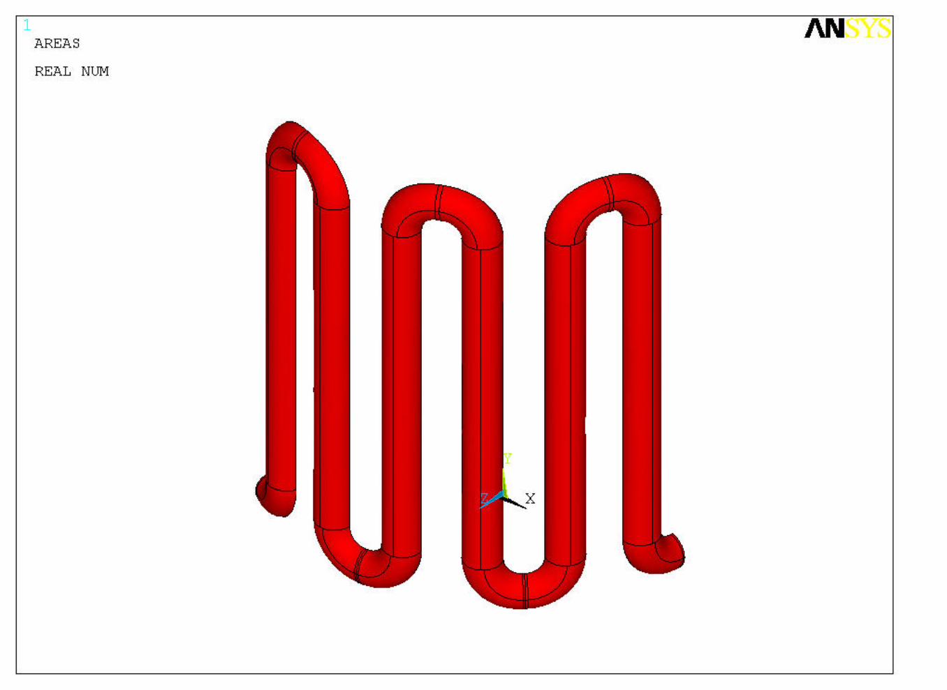
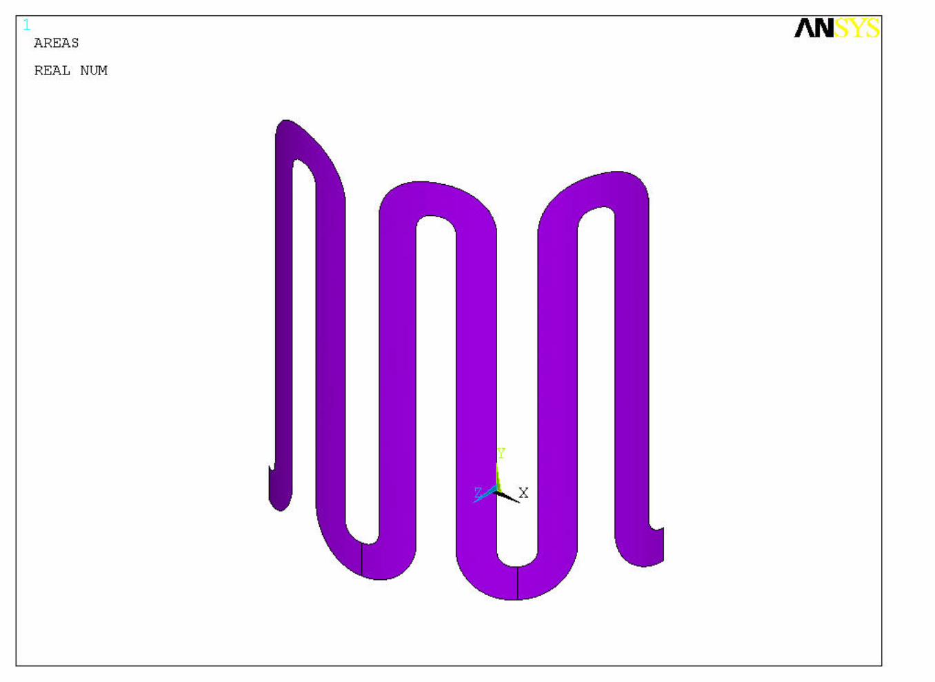
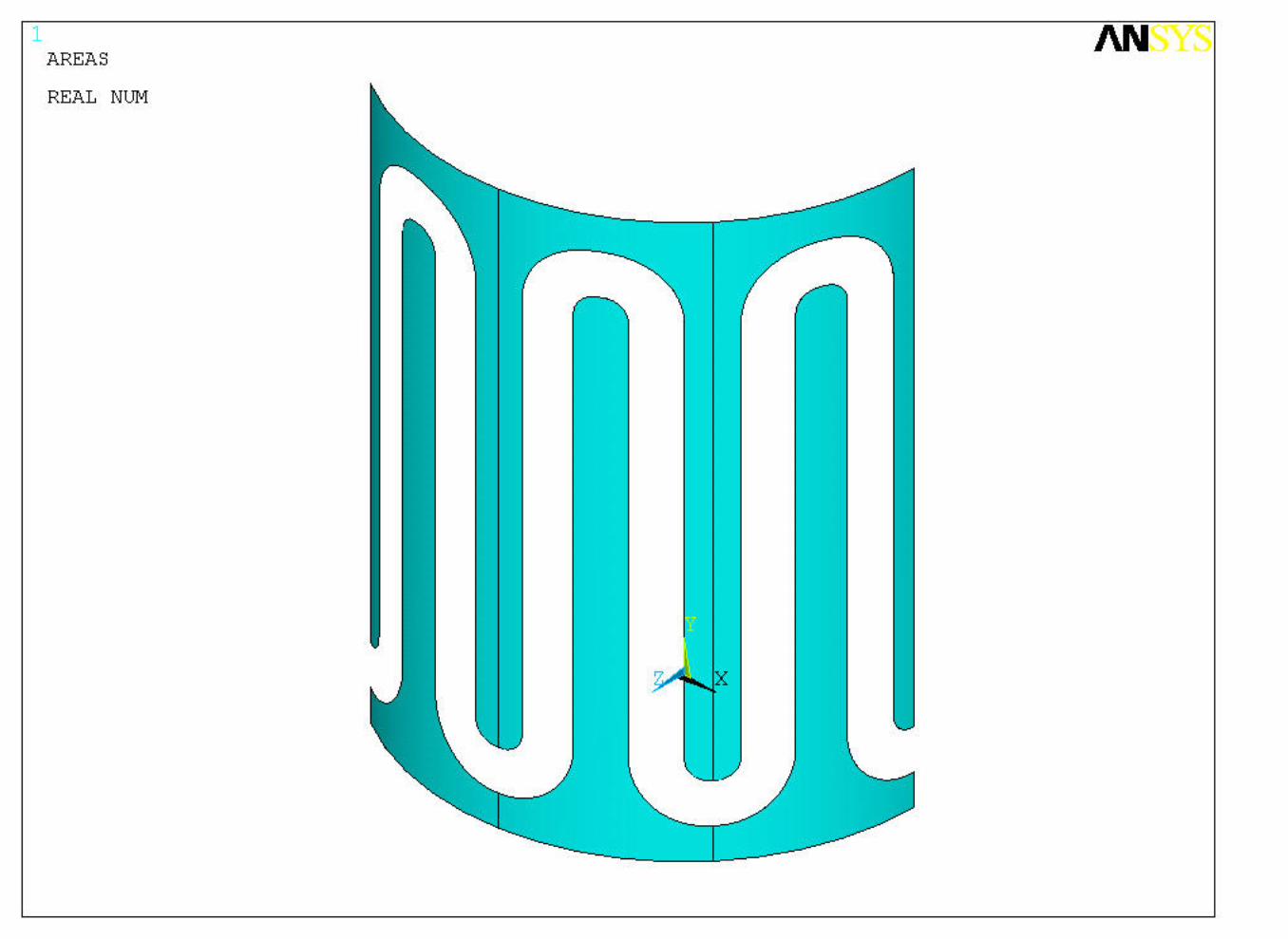
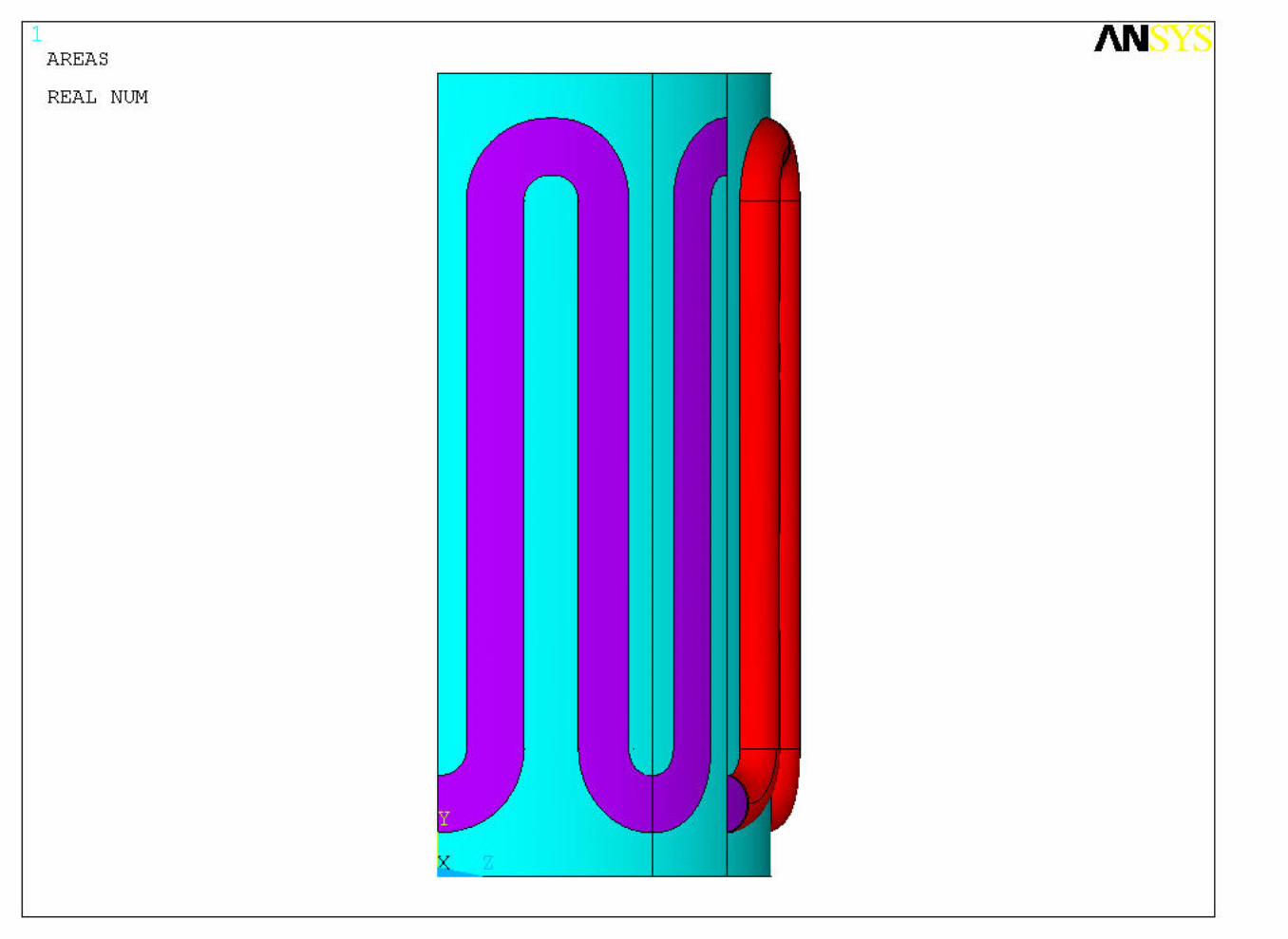
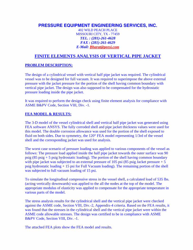
FINITE ELEMENTS ANALYSIS OF VERTICAL PIPE JACKET PROBLEM DESCRIPTION: The design of a cylindrical vessel with vertical half pipe jacket was required. The cylindrical vessel was to be designed for full vacuum. It was required to superimpose the above external pressure with the jacket pressure for the portion of the shell having common boundary with vertical pipe jacket. The design was also supposed to be compensated for the hydrostatic pressure loading inside the pipe jacket. It was required to perform the design check using finite element analysis for compliance with ASME B&PV Code, Section VIII, Div. -1. FEA MODEL & RESULTS: The 3-D model of the vessel cylindrical shell and vertical half pipe jacket was generated using FEA software ANSYS. The fully corroded shell and pipe jacket thickness values were used for this model. The double corrosion allowance was used for the portion of the shell exposed to fluid on both sides. Due to symmetry, the 120° FEA model representing 1/3rd of the vessel shell and the corresponding jacket was used for analysis. The worst case scenario of pressure loading was applied to various components of the vessel as follows: The pressure load applied inside the half pipe jacket towards the outer surface was 90 psig (85 psig + 5 psig hydrostatic loading). The portion of the shell having common boundary with pipe jacket was subjected to an external pressure of 105 psi (85 psig Jacket pressure + 5 psig hydrostatic loading + 15 psi for Full Vacuum loading). The remaining portion of the shell was subjected to full vacuum loading of 15 psi. To simulate the longitudinal compressive stress in the vessel shell, a calculated load of 535 lbs. (acting vertically downwards) was applied to the all the nodes at the top of the model. The appropriate modulus of elasticity was applied to compensate for the appropriate temperature in various parts of the model. The stress analysis results for the cylindrical shell and the vertical pipe jacket were checked against the ASME code, Section VIII, Div.-2, Appendix-4 criteria. Based on the FEA results, it was found that the stresses in the cylindrical shell and the vertical pipe jacket were within the ASME code allowable stresses. The design was certified to be in compliance with ASME B&PV Code, Section VIII, Div. -1. The attached FEA plots show the FEA model and results.