version 0.9 last revised september 9, 2014 - lathemagic.com magic manual.pdf · holding down the...
TRANSCRIPT

Version 0.9 Last Revised September 9, 2014
LATHE MAGIC MANUAL Copyright 2014 by Rich Schafermeyer
www.lathemagic.com
Introduction
Lathe Magic is a program that generates designs for woodturning and other lathing methods. Unlike traditional 3D modeling software, Lathe Magic lets the computer do the work. It creates new designs at the click of a button so hundreds of designs are automatically produced in a short period of time. These designs can be used as is or they can be easily modified using simple mouse and menu commands. The designs can be viewed on a monitor or saved and printed for use at the lathe.
System Requirements
Lathe Magic is a Windows computer program. It works on Windows XP, Vista, Win 7 and Win 8. It does not work on Macs unless the Mac is equipped with software that can run Window programs (not tested).
Installation
Download and extract the zip file into a location of your choice. You will find a folder labeled Lathe Magic. Within that folder you will find additional folders labeled Designs, Help, Patterns, Textures and Undo. You will also find a number of additional files needed to operate Lathe Magic
Table of Contents
Introduction .................................................................................................................................................. 1
System Requirements ................................................................................................................................... 1
Installation .................................................................................................................................................... 1
QUICK START GUIDE...................................................................................................................................... 5
3D View ..................................................................................................................................................... 5
3D Icon Bar ................................................................................................................................................ 5
Front View ................................................................................................................................................. 6
Front View Icon Bar ................................................................................................................................... 7
Tip for the First Time User ........................................................................................................................ 8
Important Menus for Quick Start .............................................................................................................. 8
New ....................................................................................................................................................... 8
Open Design .......................................................................................................................................... 9
Open Texture ........................................................................................................................................ 9
Save and Save Design As ....................................................................................................................... 9
Print ....................................................................................................................................................... 9

Lathe Magic Manual 2
Keyboard Commands ................................................................................................................................ 9
Mouse Combined with Keyboard ........................................................................................................... 10
MENUS ........................................................................................................................................................ 10
Actions Menu .............................................................................................................................................. 10
New Design ......................................................................................................................................... 10
Flip Design ........................................................................................................................................... 10
Straighten Sides .................................................................................................................................. 10
Wall Thickness and Hollow Model ...................................................................................................... 10
Drill ...................................................................................................................................................... 11
Dish ..................................................................................................................................................... 11
Step/Dish ............................................................................................................................................. 11
Set Bead/Cove/Groove/Block Size ...................................................................................................... 11
Insert Bead .......................................................................................................................................... 11
Insert Cove .......................................................................................................................................... 11
Insert Groove ...................................................................................................................................... 11
Insert Block.......................................................................................................................................... 11
Set Scale for Grow/Shrink ................................................................................................................... 11
Grow .................................................................................................................................................... 12
Shrink .................................................................................................................................................. 12
Complex End Faces ............................................................................................................................. 12
Block Actions Menu .................................................................................................................................... 12
Copy Block ........................................................................................................................................... 12
Paste Copied Block Above ................................................................................................................... 12
Paste Copied Block Below ................................................................................................................... 12
Delete Block ........................................................................................................................................ 12
Convert Block to Bead ......................................................................................................................... 12
Convert Block to Cove ......................................................................................................................... 13
Move Block Up .................................................................................................................................... 13
Move Block Down ............................................................................................................................... 13
Randomize Block ................................................................................................................................. 13
Straighten Dots ................................................................................................................................... 13
Level Dots ............................................................................................................................................ 13

Lathe Magic Manual 3
Preferences Menu ....................................................................................................................................... 13
Number of Blocks ................................................................................................................................ 13
WOOD SIZE AND FIT ................................................................................................................................ 14
Set Wood Size ..................................................................................................................................... 14
Fit to Wood Width .............................................................................................................................. 14
Fit to Wood Height .............................................................................................................................. 15
Allow Flat Sides ................................................................................................................................... 15
OTHER OPTIONS ...................................................................................................................................... 15
Set Colors ............................................................................................................................................ 15
Show All Design Dots .......................................................................................................................... 15
Hide Dimensions ................................................................................................................................. 15
Use Metric Dimensions ....................................................................................................................... 15
Set Colors Dialog Box .............................................................................................................................. 15
Restore Default Colors ........................................................................................................................ 16
View Menu .................................................................................................................................................. 16
Solid ..................................................................................................................................................... 16
Wireframe ........................................................................................................................................... 16
Points .................................................................................................................................................. 16
Adjust Light ......................................................................................................................................... 16
Help Menu .................................................................................................................................................. 16
Help ..................................................................................................................................................... 16
About ................................................................................................................................................... 16
TEMPLATES ................................................................................................................................................. 16
Template Menu ....................................................................................................................................... 17
Open Template ................................................................................................................................... 17
Make Template from Design ............................................................................................................... 17
Swap Template with Design ................................................................................................................ 17
Move Template Location .................................................................................................................... 17
PATTERNS .................................................................................................................................................... 18
What is a Pattern?................................................................................................................................... 18
Using Patterns ......................................................................................................................................... 18
Open Pattern ....................................................................................................................................... 18

Lathe Magic Manual 4
Close Pattern ....................................................................................................................................... 19
Design and Template from Pattern ..................................................................................................... 19
Making Patterns ...................................................................................................................................... 19
Make Quick Pattern ............................................................................................................................ 19
Make Standard Pattern ....................................................................................................................... 19
Save Pattern ........................................................................................................................................ 20
TEXTURES .................................................................................................................................................... 20
PRINTING ..................................................................................................................................................... 21
Print Dialog Box ....................................................................................................................................... 21
Print Preview - Design View .................................................................................................................... 21
Guide Marks ........................................................................................................................................ 21
Print Output Icons .............................................................................................................................. 22
Print Preview - 3D View .......................................................................................................................... 22
USER LICENSE .............................................................................................................................................. 23
ACKNOWLEDGEMENT ................................................................................................................................. 23

Lathe Magic Manual 5
QUICK START GUIDE
It's easy to get started with Lathe Magic. After running the file lathemagic_1.exe, you will see a screen similar to the one below:
At the top is a classic Windows menu. Beneath that are two windows. On the left is a 3D view, showing the design as it would appear in 3D. On the right is a Front view which shows an outline drawing of the design's profile. Both of these windows have an icon bar at the top which provides a variety of controls and each window responds to a variety of keyboard and mouse choices. The design is generated automatically, so each time you start Lathe Magic you will see a different design being displayed.
3D View
This window shows a 3D view of the design. No changes to the settings are typically needed, but if changes are made, they persist until changed again or until the view is reset to the default.
3D Icon Bar
The icon bar has 11 action icons. Hovering the mouse pointer over an icon for half a second will cause a descriptive label to appear. To apply an action, point at the icon with your mouse and left-click. Repeat the click to add more of the same action. From left to right:
Icon Keyboard Mouse Action 1. Rotates the model to the right Right arrow 2. Rotates the model to the left Left arrow 3. Tips the model forward Down arrow 4. Tips the model back Up arrow

Lathe Magic Manual 6
5. Zooms in on the model Insert Rotate mouse wheel towards you 6. Zooms out on the model Delete Rotate mouse wheel away from you 7. Moves the model up Home Hold left mouse button and drag up 8. Moves the model down End Hold left mouse button and drag down 9. Moves the model left Pg Up Hold left mouse button and drag left 10. Moves the model right Pg Dn Hold left mouse button and drag right 11. Resets the camera to the default Actions 1-10 have a corresponding keyboard command as indicated above. Press the key once to apply a small amount of the action. Press and hold the key to apply a continuous amount. Some actions also have corresponding mouse commands as indicated. The default 3D view shows a Solid model. This can be changed by selecting View from the menu. Wireframe shows the outline of each polygon that makes up the model. Point shows the vertices that mark the corner of each polygon. These later two choices can be helpful to check the wall thickness of a hollow model. The default 3D View background color is black. See Preferences-Set Colors for directions on how to change the background color. The default model color is a simulated wood texture. See File-Open Texture for directions on how to change the model's texture.
Front View
This window shows the design as if looking at it directly from the front. The design is shown as an outline over a dimensional grid. When the program is first started, a new design will be automatically created. This design can be easily replaced by pointing at the NEW icon at the top of the window and left-clicking the mouse. Within seconds, a new design will be created. Both the Front View and the 3D View will show this new design. For many users, this is all that is needed to make a design: keep clicking on the New button until you see a design you like, then print and go to the lathe.
Along the right hand side of the outline are a number of small red squares. The outline appears as a heavy black line except between two of the red squares where it appears as a heavy blue line. This blue line indicates the active block. In addition to the blue line, there will also be 3 small colored circles labeled one, two, and three. By moving the red square and colored circles with the mouse, you will change that portion of the design. The red squares and colored circles are referred to as Design Dots within this manual. Lathe Magic designs are made by stacking "blocks" on top of one another. The height and width of each block is defined by an upper and lower red square. By pointing at the square and holding down the left mouse button, you can drag the square to a new location and thereby change the height and width of the block. The curve of each block is defined by the hollow circles in relationship to each other and to the red squares. As you move the lower red square, you also move the circular dots which

Lathe Magic Manual 7
preserves the shape of the block. By pointing at the circular design dots and holding down the left mouse button, you can drag each of them to a new location and thereby change the profile shape. Changes to the profile are instantly reflected in the 3D View. You can also set the location of the design dots with the keyboard. Double-click on a design dot and a dialog box pops up allowing you to type in the desired X & Y location.
If the design is comprised of more than one block, you can choose another block by pointing at the black outline or a red square and left-clicking the mouse button. The outline for this newly selected block will change to blue and its control dots will appear. By this means, each block in the design can be changed as desired. There are many more actions that can be performed to create or modify a Lathe Magic design. Read through the full manual to understand all that can be done.
Front View Icon Bar
The icon bar for the Front View has 12 action icons. Hovering the mouse pointer over an icon for half a second will cause a descriptive label to appear. To apply an action, point at the icon with your mouse and left-click. Repeat the click to add more of the same action. From left to right:
Icon Keyboard Mouse Action 1. Generates a new model N 2. Flips the model upside down F 3. Change the width and height Click on icon, then click on grid at desired width and height 4. Change the height Click on icon, then click on grid at desired height 5. Change the width Click on icon, then click on grid at desired width 6. Zooms out Rotate mouse wheel towards you 7. Zooms in Rotate mouse wheel away from you 8. Moves the design up Hold left mouse button and drag up 9. Moves the design down Hold left mouse button and drag down 10. Moves the design left Hold left mouse button and drag left 11. Moves the design right Hold left mouse button and drag right 12. Resets the view to the default
Some actions have a corresponding keyboard command as indicated above. Press the key once to apply. Some actions also have corresponding mouse commands as indicated. If key and mouse actions do not appear to work, you may need to click on the Front View window to make it active, then use the mouse or keyboard.

Lathe Magic Manual 8
There is also a pop-up menu that will appear when you click the right mouse button anywhere in the Front View window. To apply an action, left click on the menu item. To close the menu, left click anywhere away from the menu box. New Design and Flip apply to the overall design. Insert allows a new block of the selected type to be added to the design. The other choices apply to the selected block indicated by the blue lines. Convert Selected Block To… changes the shape of the block to the selected type. Move Selected Block… allows the block to be repositioned in the design. Randomize Selected Block will apply the same design equations used to make a new design but only to that block. Straighten Dots will change the profile of the selected block into a straight line between the two red squares, with the circles evenly spaced in 1-2-3 order. This can be a handy way to recover if movement of the design dots leads to a convoluted design. Delete Selected Block removes it from the design. The top and bottom of the design are flat faces and cannot be selected. They also do not have design dots to change their profile. The top and bottom red squares can be dragged to the centerline so the flat faces disappear. See Actions-Complex End Faces for another way to modify the end faces.
Tip for the First Time User
Lathe Magic's real value appears when you let the computer do the work and use your eyes to choose an attractive design. Although you can use Lathe Magic tools to design from scratch, that's the hard way to go. To see what's possible, repeatedly click the N button on your keyboard. Within a minute, you'll easily generate 50-100 unique designs. Think of Lathe Magic as an idea generator - you can then add your own touches to a design to make it your own.
Important Menus for Quick Start
Details about the many menu choices are found later in this manual. For new users, the following highlights a few important menu items. The File menu is the same as for most Windows program. Left click once on the word File, then scroll down and left click once on the desired menu option. Menu choices in black are available for immediate use. Menu choices in gray are not available until certain conditions are met. New: same action as selecting the NEW icon in the Front View window. Automatically generates a new design.

Lathe Magic Manual 9
Open Design: opens a previously created design saved by you or another user. Lathe Magic designs are files ending in .lmd Open Texture: applies a texture to replace the default wood texture. Any .jpg or .bmp photo can be used as a texture. A couple of example textures are included with the Lathe Magic program, others can be downloaded from lathemagic.com, or you can make your own. More information about textures can be found later in this manual. Save and Save Design As: Saves the current design into a file ending in .lmd. Save overwrites the last opened design. Save Design As creates a new file. Print: Creates a print preview of the design. The design can either be printed right away or saved as a .ddc or .exe file for later printing. More details about printing can be found later in this manual. The Edit menu offers two choices: Undo and Redo. These provide up to 100 levels of undo in a con-tinuous loop. The Help menu provides a direct link to the help information on lathemagic.com.
Keyboard Commands
A number of actions can be executed using the keyboard:
Key Action N New design F Flip design S Straighten side of selected block I Straighten side of design L Level side of selected block U Move Block Up Ctrl + P Print Ctrl + X Delete selected block Ctrl + C Copy selected block Ctrl + V Paste copied or deleted block above selected block Ctrl + Z Undo design Ctrl + Y Redo design D Set dot on diagonal * V Set dot vertical * H Set dot on horizontal *
* D, V, and H are helpful for aligning design dots. Type the key, then click on the red square or circular dots to apply the effect:
V applied to a design dot aligns the dot vertically to the red square below it. H applied to a design dot aligns the dot horizontally with the red square below it. If you first click H or V, then hold down Ctrl key while clicking on design dot, it will align with the red
square above it. D applied to a 1 or 3 circular dot aligns the dot on a straight line through the adjacent red square. If
the dot is labeled 1, it will align with the dot labeled 3 in the block above it. If the dot is labeled 3, it will align with the dot labeled 1 in the block below it. If the dot is labeled 2, nothing happens.

Lathe Magic Manual 10
Mouse Combined with Keyboard
Two other keys can be used in combination with the left mouse button. While pointing at a red square, hold down the left mouse button and also hold down either the CTRL or the ALT key.
CTRL Moves the red square without moving the circular design dots in the selected block. Normally, the circular dots move with the red square.
ALT Moves red square and everything above it (red squares and circular design dots for the
selected block and all higher blocks).
While pointing at a circular design dot, hold down the left mouse button and also hold down the CTRL key.
CTRL Moves all the circular design dots in the selected block. Normally, the circular dots move individually.
MENUS
Actions Menu
A large number of design choices are provided by this menu. Most apply to the overall design. Choices that apply to individual blocks are found under the Block Actions menu. New Design: Same as clicking on NEW icon on Front View window. Generates a new design using the default code or a pattern if opened. New Cylinder: Creates a single block design with vertical walls which appears as a cylinder in 3D. Helpful if starting a design from scratch. Flip Design: Flips design from top to bottom. Straighten Sides: The right pointing triangle indicates there are multiple choices for this menu item. Vertical with Top Square aligns the profile as a straight line from top to bottom, located at the width of the top red square. This creates a cylindrical design. Vertical with Bottom Square aligns the profile as a straight line from top to bottom, located at the width of the bottom red square. This also creates a cylindrical design.
Between Bottom and Top Square aligns the profile into a straight, angled line from top to bottom. These choices eliminate most of the design provided by the automatic code and allows the user freedom to create a design from scratch. Wall Thickness and Hollow Model: Hollow Model adds extra blocks inside a design. These blocks mirror the outside profile, creating a thin walled model. Wall Thickness opens a dialog box that allows the user

Lathe Magic Manual 11
to set the thickness of the skin. An alternate way to hollow a model is to first apply Dish or Step/Dish (see below) then move the design dots to hollow out the interior. Drill: The right pointing triangle indicates there are multiple choices for this menu item. Set Drill Size opens a dialog box that allows the user to set the diameter and depth of drilling. Top drills a hole in the flat top face of the design. Bottom drills a hole in the flat bottom face of the design. Through drills a hole all the way through the model. It's up to the user to set the drill diameter and depth to values suitable for the design. Dish: The right pointing triangle indicates there are multiple choices for this menu item. Top replaces the top face with a slightly curved surface. By selecting the red square at the top centerline and dragging it down, the dish can be made as deep as desired. As moving the top square does not move the circular design dots, the user needs to move those dots to create the desired interior profile. See top of the figures to the right. Bottom replaces the bottom face with a slightly curved surface. By selecting the red square at the bottom centerline and dragging up, the dish can be made as deep as desired. The user needs to move the circular design dots to create the desired interior profile. Step/Dish: The right pointing triangle indicates there are multiple choices for this menu item. Similar in action to Dish except a small flat face is left at the outer edge of the top or bottom surface. See bottom of figures above.
Set Bead/Cove/Groove/Block Size: This opens a dialog box where the user can set the height to use with the following commands. Insert Bead: A bead is an outwardly convex surface. The right pointing triangle indicates there are multiple choices for this menu item. Above inserts the bead as a new block above the currently selected block indicated by the blue profile outline. Below inserts the bead as a new block below the currently selected block. Insert Cove: A cove is an inwardly concave surface. This menu item behaves the same as Insert Bead. Insert Groove: A groove is a sharp-edge cut into the surface. The top and bottom of the groove are horizontal. This menu item behaves the same as Insert Bead. Insert Block: Adds a block above or below the selected block. The user than moves the circular design dots to change the profile. Set Scale for Grow/Shrink: Opens a dialog box that allows the user to set a value between 1 and 5. The value is used with the subsequent grow/shrink menu choices. A value greater than 1 grows an object by that ratio or shrinks an object by the inverse of the ratio (e.g. a value of two doubles the size for growth

Lathe Magic Manual 12
or halves it for shrink). A value of 1 has no effect. Using values close to 1 is preferred; the default value is 1.15. Grow: The right pointing triangle indicates there are multiple choices for this menu item. Height grows the design's height by the ratio set previously. Width grows the design's width by the ratio set previously. Both grows the design's height and width by the ratio set previously. Shrink: The right pointing triangle indicates there are multiple choices for this menu item. Height shrinks the design's height by the ratio set previously. Width shrink the design's width by the ratio set previously. Both shrinks the design's height and width by the ratio set previously. Note: Growing and shrinking the design can also be done visually by using the third to fifth icons found on the Front View's icon bar. Click on the icon, then click on the grid to set the height, width or both. Complex End Faces: The right pointing triangle indicates there are multiple choices for this menu item. By default, end faces of a new design are horizontal and flat. Selecting Top when unchecked inserts a new horizontal block at the top of the design. A new red square will also appear at the centerline of the face. Clicking on the end face will now show a blue line color and 3 circular control dots that can be moved to curve the top face. Selecting Top when checked removes the inserted block and restores a flat end face. Bottom performs the same actions but for the bottom face.
Block Actions Menu
A large number of design choices that apply to individual blocks are provided by this menu.
Copy Block: Copies the selected block into memory. It remains in memory until another block is copied. This allows you to insert multiple copies of the same block into the design. You can also transfer a block from one design to another. Paste Copied Block Above: Inserts the copied block above the selected block. Paste Copied Block Below: Inserts the copied block below the selected block. A note on copied and pasted blocks: What is copied is the position of the lower red square and the three circular design dots above it. When
pasted, the appearance will depend upon the location of the red square in the block above the pasted block. If that red square is much further to the right or left of the original upper square, the curve shape may look more different than expected. Delete Block: Removes the selected block from the design. It does not make a copy of the block so copy the block before deletion. Convert Block to Bead: Changes the profile of the selected block to an outwardly convex surface the same height as the selected block it replaces.

Lathe Magic Manual 13
Convert Block to Cove: Changes the profile of the selected block to an inwardly concave surface the same height as the selected block it replaces. Move Block Up: Moves the selected block up one position in the design. Move Block Down: Moves the selected block down one position in the design. A moved block can behave like a pasted block: When moved, the appearance will depend upon the location of the red square in the block above the moved block. If that red square is much further to the right or left of the prior upper square, the curve shape may look more different than expected. Randomize Block: Applies the same design equations used to make a new design but only to the selected block. Straighten Dots: Changes the profile of the selected block into a straight line between the two red squares, with the circles evenly spaced in 1-2-3 order. In addition to making a flat surface, this can be a handy way to recover if movement of the circles leads to a convoluted design or the design dots fly off the screen. Level Dots: Changes the profile of the selected block into a straight horizontal line even with the lower edge of the selected block. This can be a useful way to flatten the top or bottom face.
Preferences Menu
Number of Blocks: Opens a dialog box that allows the user to change the number of blocks in automatically-generated designs. To change the value, type a new number in the box, drag the middle scrollbar to the right or left, click on an arrow to change the value by 1, or click on the space between the scroll bars and arrows to change the value by 4. The scroll bar can be set as low as 1 and as high as 20. There are three radio buttons. Only one button can be chosen at a time. Click on a button to choose that value.
The Maximum radio button means a design created with the New icon or New menu choice will have one to as many blocks as shown in the number box. The Minimum radio button means a design created with the New icon or New menu choices will have at least as many blocks as shown in the number box up to a maximum of 20. Exactly means each new design will have the number of blocks shown in the number box. Click on the OK button to apply the selection to future designs. Click on the Cancel button to close the dialog box without changing any settings.

Lathe Magic Manual 14
Profile Smoothness: Opens a dialog box that allows the user to change the number of line segments in the curves that make up the profile of the design. The higher the number of segments, the smoother the curve but the slower it is to calculate and display the model. With fewer segments, the straight lines that make up the curve become more visible. The default value of 16 is typically sufficient to display a smoothly flowing curve. A value of 1 simplifies the curve to a straight line between the red squares, no matter where the circular design dots are placed. A value of 3 will show a curve made up of three straight line segments. To change the value, type a new number in the box, drag the middle scrollbar to the right or left, click on an arrow to change the value by 1, or click on the space between the scroll bars and arrows to change the value by 4. The scroll bar can be set as low as 1 and as high as 32. There are six radio buttons, four in one group and two in another. Only one button in each group can be chosen at a time. Click on a button to choose that value. Selected Block Only applies the settings to just the block outlined in blue. All Blocks applies the settings to all blocks. Selected Block and All Above applies the settings to the selected block and all blocks stacked above the selected block. Selected Block and All Below applies the settings to the selected block and all blocks stacked below the selected block. Apply to Current Design Only means the new setting is not persistent and will reset to the default value of 16 as soon as a new design is made with the New button or New menu item. Apply to All designs will make the new value apply to all blocks of all future designs until reset. Click on the OK button to apply the selection to the design. Click on the Cancel button to close the dialog box without changing any settings.
WOOD SIZE AND FIT
Set Wood Size: The default behavior of Lathe Magic is to create a randomly sized design. The user can choose to have the design fit a desired wood length and/or width. This menu choice opens a dialog box that lets the user set the wood width and height. Wood size is outlined in green on the Front View (see image to right). Fit to Wood Width: Design is automatically resized to fit the wood width. The width is set so that the design's circular cross section just fits within the boundaries of the wood. If the wood is not entirely square, set wood size to the shorter of the two widths. Depending upon your wood turning skills, it may also be hard to center the wood on the lathe. To ensure a completely

Lathe Magic Manual 15
circular cross section, use a wood size slightly smaller than the actual wood width. This selection persists until it is turned off by re-selecting the menu item. Fit to Wood Height: Design is automatically resized to fit the wood height. This selection persists until it is turned off by re-selecting the menu item.
Allow Flat Sides: Unlike Fit to Wood Width which forces the design to fit the wood and have a circular cross section, this choice allows part of the design to extend beyond the wood width. When turned, this results in parts of the design being flat (see image on left). When this choice is selected, the wood outline on the Front View is rotated 90 degrees. The dotted line shows the limits of a circular cross-section (see image on right). The flattened sections will be the areas of design between the dotted and outer solid green lines. More of the side will flatten as the design
approaches the solid green line. If the design passes to the outside of the solid green lines, it will be a square cross-section and the Front View will reflect the flattened areas. If making a turning using this setting, the wood MUST be perfectly square AND perfectly centered on the lathe so all four sides look the same.
OTHER OPTIONS
Set Colors: Opens a dialog box that allows the user to set various colors. Colors persist even after program is closed. See below for more details. Show All Design Dots: To avoid clutter, only the circular design dots for the selected block are shown. Clicking on this menu choice turns on all design dots for all blocks, which can be helpful when creating smoothly flowing shapes. Choosing it again turns it off. Hide Dimensions: Turns off the dimensions along the bottom and right side of the grid. Click it again to turn dimensions back on. Use Metric Dimensions: If unchecked (default), uses inch measurements. If checked, uses centimeter measurements. This changes the grid spacing to reflect the difference between inches and centimeters. It also converts drill, wood, hollow thickness, and bead/cove/groove values as well as printing to be in the same units.
Set Colors Dialog Box
The colors used in the program can be modified to suit the users taste. A dialog block will appear showing the current color assignments (see image on next page). To change a color, click on a color square. A standard Windows color dialog box will appear - select the new color and click OK to apply or Cancel to keep the existing color. This action can be repeated for as

Lathe Magic Manual 16
many colors boxes as desired. The new color choices are not applied until the Set Colors dialog box is closed by clicking on OK. Restore Default Colors: Color changes are persistent and will remain even after closing the program. To restore the original default color scheme, click on this button. OK: Applies the new colors to the program. Cancel: Closes the dialog box without changing any colors.
View Menu
This menu lets you set how the 3D model is displayed. Solid: This is the default view. The design is shown as a solid model with an applied texture. Wireframe: This shows the model with all the vertices connected by a straight line. Helpful to see the interior of a hollow model. Points: This shows the model with all the vertices indicated by a single dot. Helpful to see the interior of a hollow model. Adjust Light: Opens a dialog that allows the light intensity to be changed. Default values are 400 for light distance and 1200 for light intensity. Higher values for light distance puts the light farther from the model, making it less bright. Higher values for light intensity makes the light brighter. Click on Restore Default Lights to return the lights to the original settings.
Help Menu
Help: This menu item gives you a link to lathemagic.com where you can view tutorials or go to the support blog. About: Shows the version of the program.
TEMPLATES
A template is a separate design that appears behind the active design. A template can serve two purposes, either to act as a design guide or to be part of a pattern (see Patterns in a later section). The template is outlined in orange as seen in the images below.

Lathe Magic Manual 17
To use as a design guide, simply drag the red squares to new locations that match the underlying template. Then select a block and adjust the circular design dots to match the profile. The design and template do not have to contain the same number of blocks. In the case illustrated above, the template (orange) is a 5 block design and the new design (black) is only 3 blocks. The lower 2 blocks have been adjusted so they match as shown in the image at the right.
Template Menu
There are two ways to make a template. Open Template: This menu choice opens a standard Windows file dialog highlighting Lathe Magic design files (.lmd). Any already saved Lathe Magic design can be used as a template. Make Template from Design: This makes a copy of the current active
design and makes a template from it. Because the design and template are identical, the template will not be visible until a change is made in the active design.
Several menu choices are not available until a template exists. Close Template: Template is no longer visible. Swap Template with Design: The template becomes the active design and the active deign becomes the template. This allows the user to make changes to the underlying template if needed. This can be useful especially if making two-part designs. Move Template Location: This allows the template location to be moved up or down on the grid. The template in the image to the left has been moved up by 2.5 inches. This is especially useful when making two-part designs as shown. If you need to save the template design as well as the

Lathe Magic Manual 18
active design, first save the active design, swap the template with the design, then save again. Use a similar name when saving both parts (for example, filename_partA and filename_partB).
PATTERNS
Whenever the New button is clicked, a design is automatically created using a built-in equation. This equation is made so that it generates a wide variety of designs for you to choose from; however, sometimes you may want a specific kind of item like a bowl or a pen. In that case, you can use a pattern to make these more specific types of objects.
What is a Pattern?
A pattern is comprised of 3 parts: two templates and a definition table. When a pattern is in use and the New button is clicked, designs are generated based on differences between the pattern's two templates as controlled by the definitions. When a pattern is opened, one part of the pattern is shown as an orange outline and the other part is outlined in black, as shown in the image below. Part of the orange outline is visible while other parts may be hidden by the black outline. Designs made while a pattern is active will match the outline where only black shows and randomly fall in between the areas which show both black and orange.
Designs based on patterns are made block by block and design dot by design dot. For Quick patterns, all the blocks are visible, all are of variable height (as defined by the difference between the red squares in the two templates) and the overall design height is variable. For Standard patterns, a definition table can be used to make some blocks randomly invisible, allow some blocks to be of fixed height, put adjacent blocks into groups and then set whether the group is of fixed height or not, and allow the overall design to be of fixed height. Details on using a definition table will be found later in this manual.
Using Patterns
You can use patterns in Lathe Magic without knowing how to create them. The following three choices from the Pattern menu allow you to use already made patterns. Open Pattern: This menu choice opens a standard Windows dialog highlighting Lathe Magic pattern files (.lmp). Choose the desired

Lathe Magic Manual 19
pattern. Now whenever the New button or New menu item is chosen, the design will fit within the boundaries defined by the pattern. Close Pattern: This choice closes the pattern and returns to using the built-in equation for new designs. Design and Template from Pattern: This menu choice replaces the currently displayed design and template with the two templates that define the active pattern.
Making Patterns
There are two types of patterns that you can make: Quick and Standard. Make Quick Pattern: This menu choice will create a pattern from the existing design and template. Both the design and template must have the same number of blocks otherwise a warning will be given. The simplest way to make a quick pattern is to first start with a design you like. Then from the template menu choose Make Template from Design. At this stage, the template won't be visible as it exactly matches the design. Now make any changes to the design you desire. The bigger the differences, the greater variation in designs that will be generated by the pattern. Finally choose Make Quick Patterns from the pattern menu. Click on the New icon and you will see that the new designs being generated are constrained by the pattern you just made. Save Pattern: Choose this menu item to save the quick pattern you’ve made. Make Standard Pattern: The first part of making a standard pattern is the same as making a quick pattern. Start with a design you like, from the template menu choose Make Template from Design, then make changes to the design. Next click on Make Standard Pattern. A two-part dialog box will appear. The first part will show a table with 4 columns and multiple rows:
Column 1 shows the block numbers starting with 1 and ending with the number of blocks in the design. In the example below, there are 7 blocks. Block 1 is the bottom-most block in the design and Block 7 is the top-most (the reverse of their position in the dialog).
Column 2 shows group numbers. When a pattern is first created, all blocks are automatically assigned to group 1. Blocks can be assigned to a new group by typing in a number, for example 2 for blocks 5-7. Only adjacent blocks can be in a group. Group numbers should start with 1 and increase sequentially with no gaps.
Column 3 shows check boxes. If checked, this block is always present in the design. When a pattern is first created, all blocks are automatically checked to be visible. If you uncheck a block, the block has a 50% chance of appearing in a design.
Column 4 shows another set of check boxes. If unchecked, this block is of variable height. When a pattern is first created, all blocks are automatically unchecked. If you check a block, the block will always be made the same height as defined by the orange template.
After clicking OK, another set of rows will appear: one row for each group and one for the entire design. The check box sets whether a group or the overall design are of fixed height or not. When a
Lathe Magic Manual 20
pattern is first created, all blocks are automatically unchecked. You can check the boxes to make some groups and/or the entire design of fixed height.
It's possible to over constrain a pattern by making too many blocks, groups or the entire design of fixed height; if so, you may get unusual or broken designs. In that case, uncheck some groups so the program has a chance to adjust.
Changes made to the definition table are persistent as long as a pattern is open. You can re-click on Make Standard Pattern to make further adjustments before saving. You can also click on Make Standard Pattern if you want to modify an already made Quick pattern. Save Pattern: Used to save either a quick or a standard pattern file. These files end in .lmp
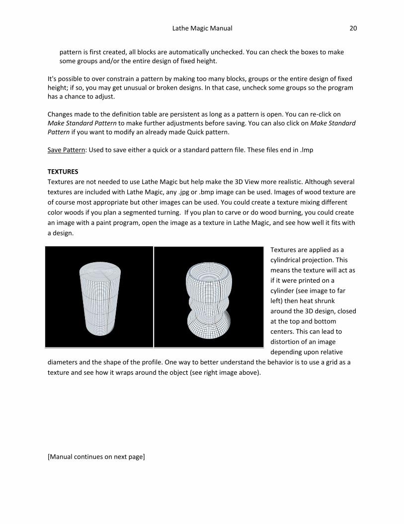
TEXTURES
Textures are not needed to use Lathe Magic but help make the 3D View more realistic. Although several
textures are included with Lathe Magic, any .jpg or .bmp image can be used. Images of wood texture are
of course most appropriate but other images can be used. You could create a texture mixing different
color woods if you plan a segmented turning. If you plan to carve or do wood burning, you could create
an image with a paint program, open the image as a texture in Lathe Magic, and see how well it fits with
a design.
Textures are applied as a
cylindrical projection. This
means the texture will act as
if it were printed on a
cylinder (see image to far
left) then heat shrunk
around the 3D design, closed
at the top and bottom
centers. This can lead to
distortion of an image
depending upon relative
diameters and the shape of the profile. One way to better understand the behavior is to use a grid as a
texture and see how it wraps around the object (see right image above).
[Manual continues on next page]

Lathe Magic Manual 21
PRINTING
For many users, it will be impractical to have a computer monitor or tablet near the lathe so you’ll want to print a paper copy. To print, first select Print from the File menu. The Print dialog box will appear.
Print Dialog Box
Created by: Include your name if you wish Design Name: Give your design a name. Most of the time, you'll want to use the same name you used to save the design. Date: The date the design is printed is automatically included. You can insert an alternate date if you wish. Fit to 1 Page: Some designs will be larger that can fit on one page. If unchecked, the design will be printed full size on as many pages as needed. This allows you to cut out the outline and use it as a template when you are working at the lathe. If this box is checked, the design will be reduced to fit on 1 page which gives a more convenient overview of the design.
Include Guide Marks: Lathe Magic can calculate special marks which can aid you in recreating the design at the lathe. These will be described in the next section. Include 3D View: If checked, a copy of the 3D View will be placed on a separate page so it too can be printed. The size can be set to minimize the amount of ink used during printing.
Print Preview - Design View
An example of the print output is shown to the right. At the top is a menu and a set of icons. Below is the page that will be printed. The Header shows the object and designer names, the overall dimensions of the design, and the number of pages the design fits on. The Design itself is shown outlined in red. The centerline and the base line are in blue. The grid is in black. These colors can be changed with the Preferences-Set Color menu item. The Footer reminds you and anyone you give a copy of the design to how the design was made and the distribution rights. For more details, see section on User License later in this manual. Guide Marks appear along the left hand side of the grid. These marks are identified automatically by

Lathe Magic Manual 22
Lathe Magic. The longer heavy black lines identify the top and bottom of each block. Many times the design will have a transition at block boundaries. The shorter heavy blue lines identify changes in direction of the profile. For this example, two are shown. The topmost guide mark shows where the profile, which had been curving out, has started to curve back in. The lower guide mark shows where the curve stops and the end of the design flattens out near the base. At the lathe, it is helpful to know the position of these points so you can accurately reproduce your design. This design only has 5 guide marks but some designs might have 16 or more depending upon the complexity of the design. The colors can be changed with the Preferences-Set Color menu item. Print Output Icons
Icon Result 1. Door Closes the print preview 2. Left triangle with line Go to first page of print preview 3. Left triangle Go to previous page 4. Right triangle Go to next page 5. Right triangle with line Go to last page of print preview 6. Box with ? Mark Jump to x page of print preview 7. Printer Print document * 8. Floppy Disk Save print preview document for later printing ** 9. Zoom Change size of print preview * When chosen, standard Windows printer dialog appears. You can choose to print all pages or only select pages. ** You have two file formats to choose from: a .ddc or a self-extracting .exe file. To print after saving, find the file in your hard drive folder and execute the file by double-clicking on it. .ddc uses ddoc.exe which is supplied with Lathe Magic (see Acknowledgements later in this manual).
Print Preview - 3D View
An example of the 3D view output is shown. This will be found as the last page of the print preview.

Lathe Magic Manual 23
USER LICENSE
Lathe Magic is being offered to the public as freeware. In return, the user agrees to the End-User License which restricts the user from profiting from selling the Lathe Magic program, designs and patterns. Users can make and sell real objects based on Lathe Magic designs, and they can make and give away but not sell Lathe Magic designs and/or patterns. See the separate End-User License for full details on your rights and limitations while using Lathe Magic. (Note that this paragraph is not the End-User License Agreement; the EULA is a separate document that can be downloaded from www.lathemagic.com).
ACKNOWLEDGEMENT
The Print Preview file for printing is generated by ddoc Print and Preview, a shareware program I purchased from its author Don Dickinson. From the program's manual: "Purchasing ddoc allows you the right to freely distribute ddoc.exe, ddoc_jpg.dll, ddoc16.dll, ddoc32.dll and ddoc_jpg.dll." These files are included with Lathe Magic and are needed to use the Print command.