nasa technical -memorandum coefficient, - drag qsref base-force drag coefficient, base drag clsr ef...
TRANSCRIPT
N A S A T E C H N I C A L
- M E M O R A N D U M
STATIC STABILITY, CONTROL, AND FIN LOAD CHARACTERISTICS OF A MODEL OF AN APACHE VEHICLE WITH
T-PHASE-CONTROL PACKAGE
uy FFTSiIIhm J. Monta
https://ntrs.nasa.gov/search.jsp?R=19700009460 2018-06-08T10:45:24+00:00Z
1. Report No.
NASA TM X-1942
7. Author(s)
Wi l l iam J. Monta
2. Government Access ion No.
8. Performing Organizat ion Report No. L-6835
10. Work U n i t No.
9. Performing Organizot ion Name and Address
NASA Langley Research Center
Washington, D.C. 20546
3. Recipient 's Catalog No.
4. T i t l e and Subt i t le
STATIC STABILITY, CONTROL, AND F I N LOAD CHARACTERISTICS OF A
MODEL OF AN APACHE VEHICLE WITH A COAST-PHASE-CONTROL PACKAGE
126-63-11-15-23
11. Controct or Gront No.
Hampton, Va. 23365
12. Sponsoring Agency Name and Address
National Aeronaut ics and Space Administ rat ion
14. Sponsoring Agency Code
5. Report Dote February 1970
6. Performing Orgonizot ion Code
13. Type o f Report and Per iod Covered
Technical Memorandum
115. Supplementary Notes
16. Abstroct
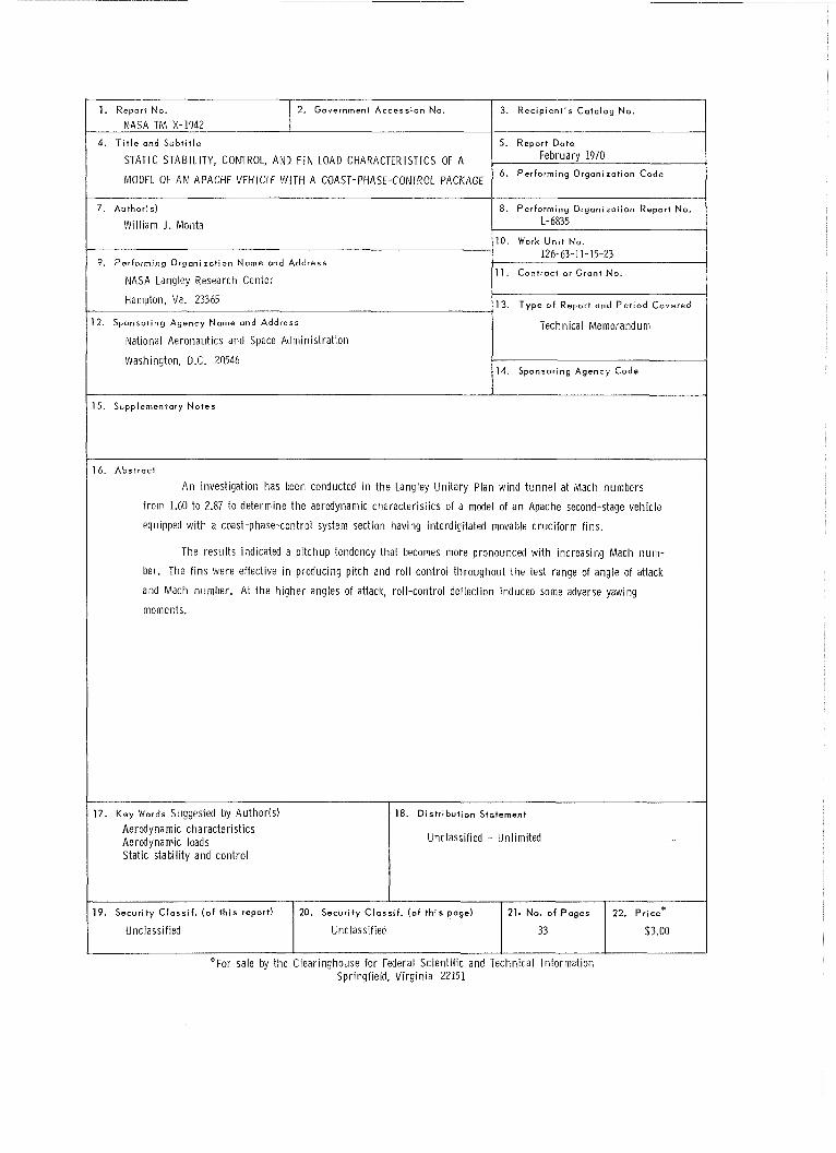
A n investigation has been conducted i n t h e Langley Un i ta ry Plan w ind t u n n e l at Mach numbers
f rom 1.60 t o 2.87 t o determine t h e aerodynamic character is t ics of a model of a n Apache second-stage vehicle
equipped w i t h a coast-phase-control system section having interdigitated movable c ruc i fo rm f ins.
The resu l t s indicated a p i tchup tendency that becomes more pronounced w i th increasing Mach n u m -
ber. The f ins were effective i n producing pi tch and r o l l contro l th roughou t t h e test range of angle of attack
and Mach number. A t t h e h igher angles of attack, ro l l -contro l deflection induced some adverse yawing
moments.
17. Key Words Suggested by Author(s1 Aerodynamic character is t ics Aerodynamic loads Static stabil i ty and con t ro l
1 18. D is t r ibu t ion Statement
I Unclassif ied - Unl imi ted
19. Secur i ty C lass i f . ( o f t h i s report)
Unclassif ied
"For sale by the Clear inghouse for Federal Scient i f ic and Technical Informat ion Springfield, V i rg in ia 22151
20. Security C loss i f . (o f t h i s page)
Unclassif ied
21. No. o f Pages
33
22. p r i c e *
$3.00
STATIC STABILITY, CONTROL, AND FIN LOAD CmRACTERISTICS OF
A MODEL OF AN APACHE VEHCLE WITH
By William J. Monta
Langley Research Center
SUMMARY
An investigation has been conducted in the Langley Unitary Plan wind tunnel a t Mach
numbers from 1.60 to 2.87 to determine the aerodynamic characteristics of a model of an
Apache second-stage vehicle equipped with a coast-phase-control system section having
interdigitated movable cruciform fins.
The resul ts indicated a pitchup tendency that becomes more pronounced with increasing Mach number. The fins were effective in producing pitch and roll control
throughout the tes t range of angle of attack and Mach number. At the higher angles of
attack, roll-control deflection induced some adverse yawing moments.
A rocket vehicle is required for use a s a simulated target to check radar acquisi-
tion systems, One proposed vehicle consists of a Nike-Ajax first-stage booster and an
Apache second stage. In an effort to achieve a minimum impact dispersion, the vehicle
was provided with a coast-phase-control system consisting of a cylindrical section with
movable cruciform fins placed between the f i r s t and second stages. The control fins a r e
interdigitated with respect to the fixed Apache fins. Flight tes t s of the vehicle revealed
unsatisfactory characteristics and necessitated a change in the design of the control fins.
It was deemed desirable to obtain a more detailed examination of the stability and control
characteristics of the vehicle that would include a determination of the load character is- t i cs of the control fins. Accordingly, the Langley Research Center has undertaken a wind-
tunnel investigation to determine these characteristics on a 0.30-scale model of the second-stage Apache vehicle equipped with the coast-phase-control system.
Tests were performed in the Langley Unitary Plan wind tunnel at Mach numbers
from 1.60 to 2.87 a t a constant unit Reynolds number near 2.0 X 10⁶ per foot
(6.6 X lo6 per meter). The tes t s were conducted over an angle-of-attack range from
about -90 to go. The 0.30-scale model was too long to provide data f r ee of shock reflec- tions below Mach 2; therefore, approximately one-half of the cylindrical section ahead of
the wings was removed to permit testing a t Mach 1.6 with a foreshortened model. I t was assumed that the loads on the control fins would not be greatly affected by this nod el
change, and that the resulting stability and control data would aid in evaluating the t rue
model characteristics a t Mach 1.6.
SYMBOLS
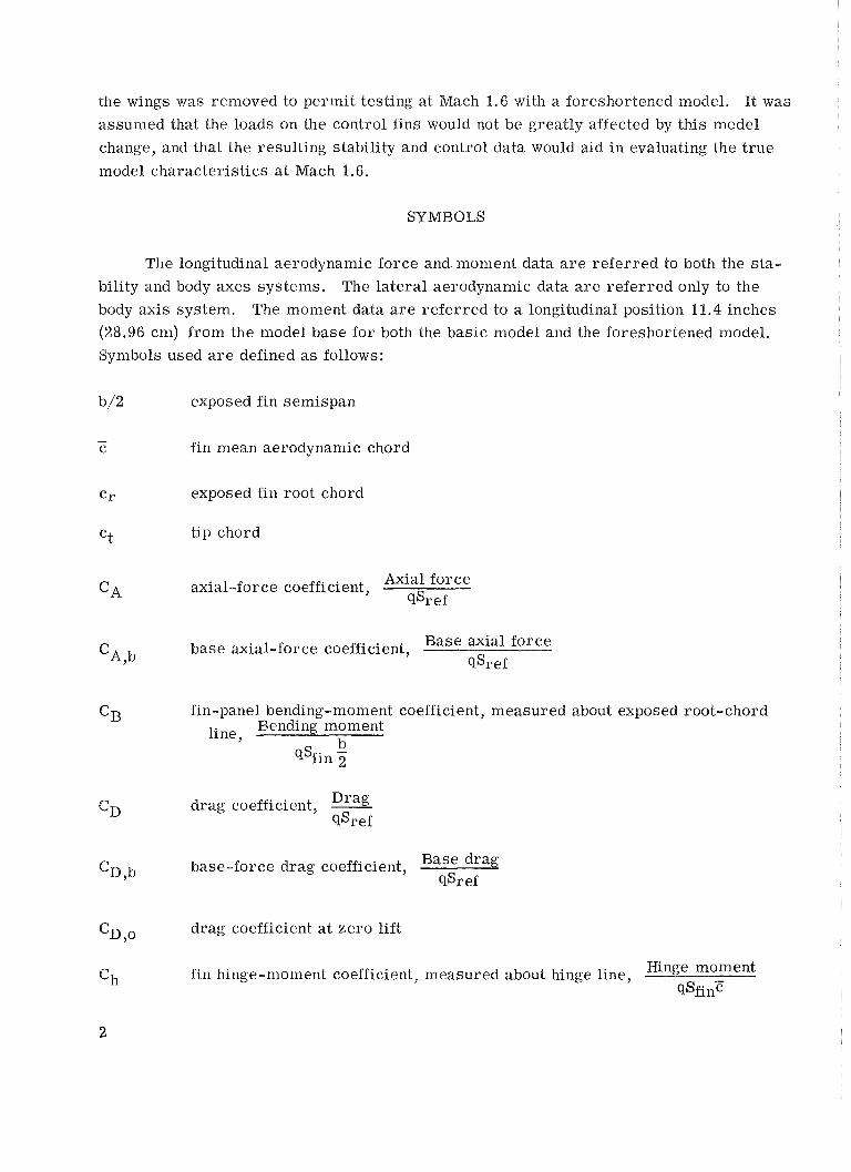
The longitudinal aerodynamic force and moment data a r e referred to both the s ta-
bility and body axes systems. The lateral aerodynamic data a r e referred only to the
body axis system. The moment data a r e referred to a longitudinal position 11.4 inches (28.96 cm) from the model base for both the basic model and the foreshortened model.
Symbols used a r e defined a s follows:
b/2 exposed fin semispan
- c fin mean aerodynamic chord
C r exposed fin root chord
Ct tip chord
axial-force coefficient, Axial force qs r ef
base axial-force coefficient, Base axial force C ~ , b qsref
Drag drag coefficient, - qSref
base-force drag coefficient, Base drag clsr ef
drag coefficient a t zero lift
fin hinge-moment coefficient, measured about hinge line, Hinge moment
~ S f i n E
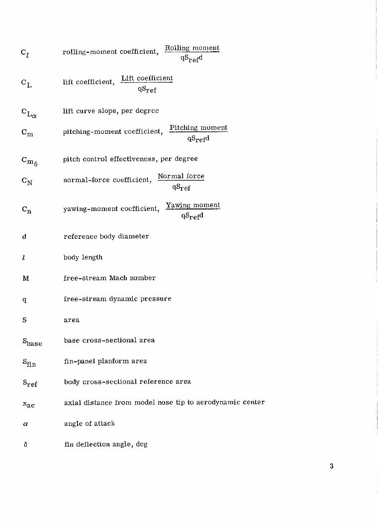
rolling-moment coefficient, qSrefd
lift coefficient, Lift coefficient
9%- ef
lift curve slope, per degree
Pitching moment pitching-moment coefficient,
qsrefd
pitch control effectiveness, per degree
normal-force coefficient, Normal force
9% ef
yawing-moment coefficient, 9% efd
reference body diameter
body length
free-stream Mach number
free-stream dynamic pressure
area
base cross-sectional area
fin-panel planform area
body cross-sectional reference area
axial distance from model nose tip to aerodynamic center
angle of attack
fin deflection angle, deg
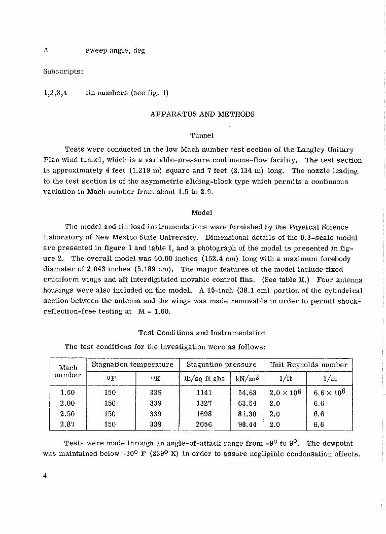
sweep angle, deg
Subscripts :
1,2,3,4 fin numbers (see fig. 1)
APPARATUS AND METHODS
Tunnel
Tests were conducted in the low Mach number test section of the Langley Unitary
Plan wind tunnel, which is a variable-pressure continuous-flow facility. The tes t section
is approximately 4 feet (1.219 m) square and 9 feet (2.134 m) long. The nozzle leading
to the tes t section is of the asymmetric sliding-block type which permits a continuous variation in Mach number from about 1.5 to 2.9.
Model
The model and fin load instrumentations were furnished by the Physical Science
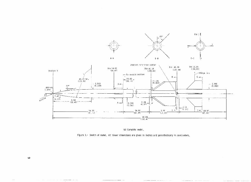
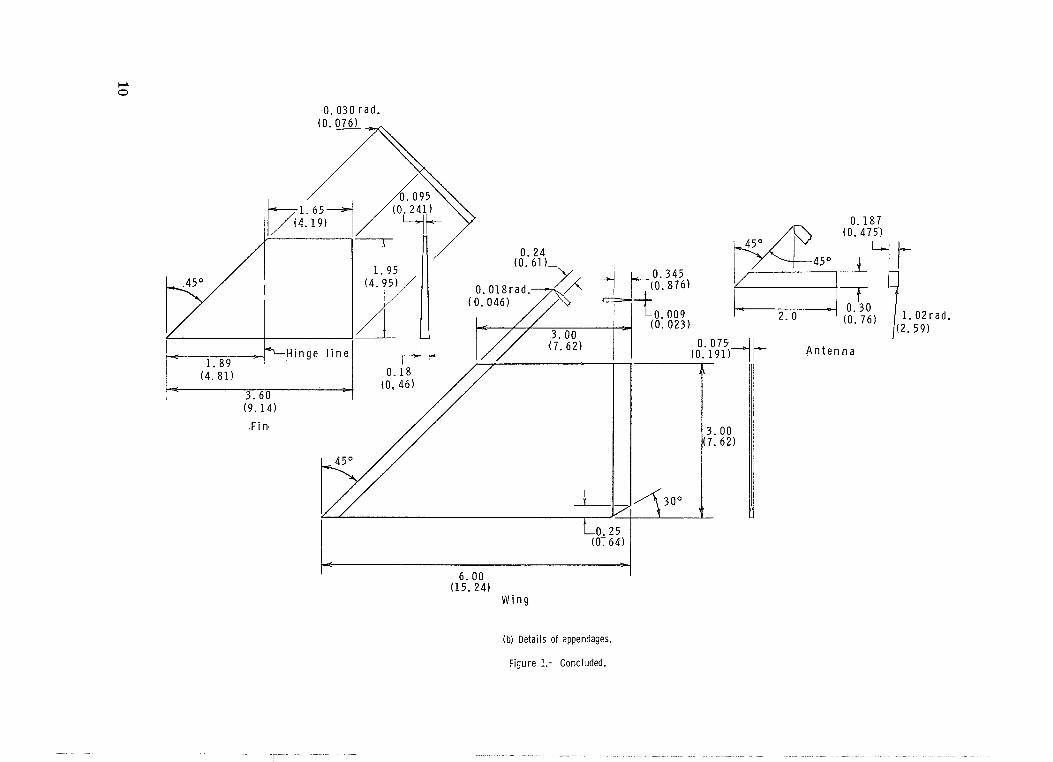
Laboratory of New Mexico State University. Dimensional details of the 0.3-scale model
a r e presented in figure 1 and table I, and a photograph of the model is presented in fig-
u re 2. The overall model was 60.00 inches (152.4 cm) long with a maximum forebody
diameter of 2.043 inches (5.189 cm). The major features of the model include fixed
cruciform wings and aft interdigitated movable control fins. (See table II.) Pour antenna
housings were also included on the model. A 15-inch (38.1 cm) portion of the cylindrical
section between the antenna and the wings was made removable in order to permit shock-
reflection-free testing at M = 1.60.
Test Conditions and Instrumentation
The tes t conditions for the investigation were as follows:
Tests were made through an angle-of-attack range from -go to 9'. The dewpoint was maintained below -30° F (23g0 K) i n order to assure negligible condensation effects.
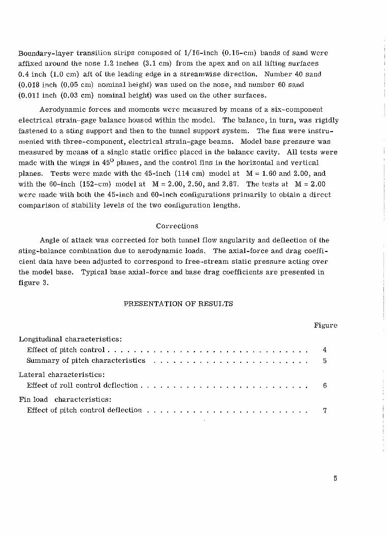
Boundary-layer transition s t r ips composed of 1/16-inch (0.16-cm) bands of sand were affixed around the nose 1.2 inches (3.1 cm) from the apex and on all lifting surfaces
0.4 inch (1.0 cm) aft of the leading edge in a streamwise direction. Number 40 sand
(0.018 inch (0.05 cm) nominal height) was used on the nose, and number 60 sand
(0.011 inch (0.03 cm) nominal height) was used on the other surfaces.
Aerodynamic forces and moments were measured by means of a six-component
electrical strain-gage balance housed within the model. The balance, i n turn, was rigidly
fastened to a sting support and then to the tunnel support system. The fins were instru-
mented with three-component, electrical strain-gage beams. Model base pressure was measured by means of a single static orifice placed i n the balance cavity. All t es t s were made with the wings in 45' planes, and the control fins i n the horizontal and vertical
planes. Tests were made with the 45-inch (1 14 cm) model a t M = 1.60 and 2.00, and
with the 60-inch (152-cm) model a t M = 2.00, 2.50, and 2.87. The tests a t M = 2.00
were made with both the 45-inch and 60-inch configurations primarily to obtain a direct
comparison of stability levels of the two configuration lengths.
Corrections
Angle of attack was corrected for both tunnel flow angularity and deflection of the
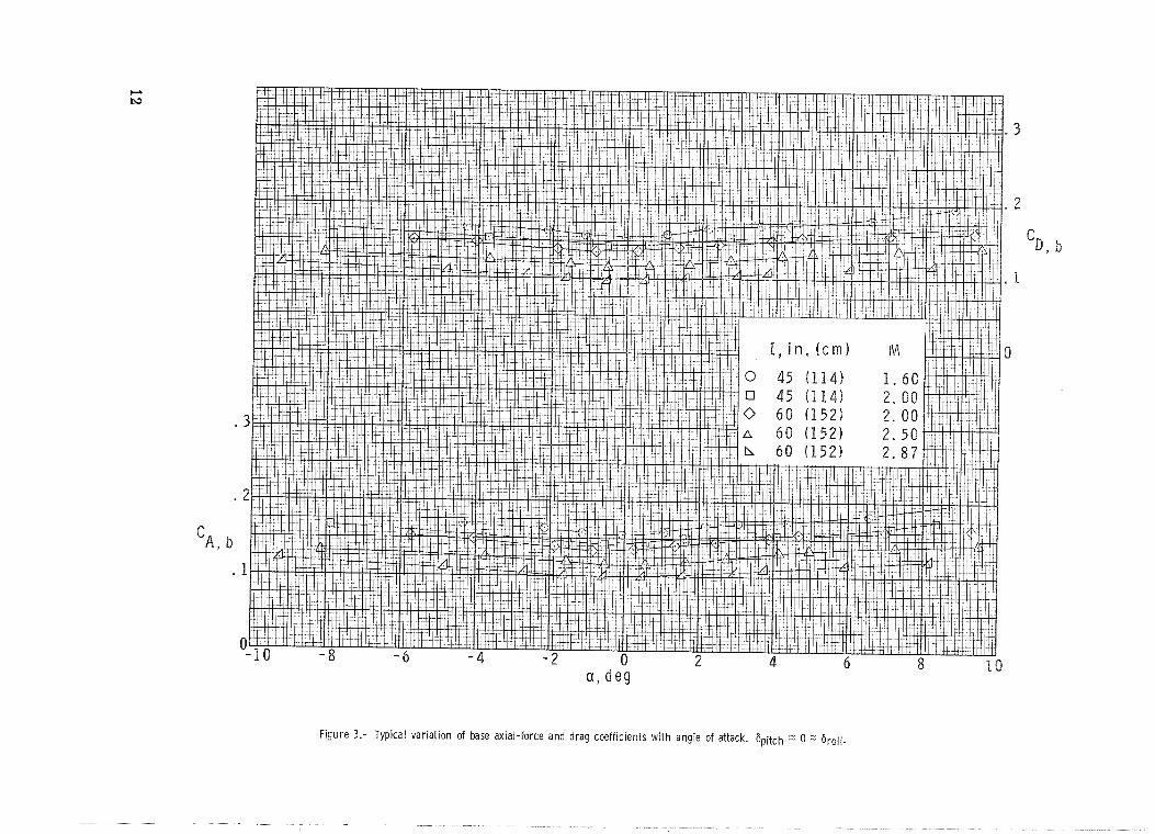
sting-balance combination due to aerodynamic loads. The axial-force and drag coeffi-
cient data have been adjusted to correspond to free-stream stat ic pressure acting over
the model base. Typical base axial-force and base drag coefficients a r e presented in
figure 3.
PRESENTATION OF RESULTS
Figure
Longitudinal characteristics:
Effect of pitch control . . . . . . . . . . . . . . . . . . . . . . . . . . . . . . . 4
. . . . . . . . . . . . . . . . . . . . . . . . Summary of pitch characteristics 5
Lateral characteristics : Effect of roll control deflection . . . . . . . . . . . . . . . . . . . . . . . . . . 6
Fin load characteristics:
. . . . . . . . . . . . . . . . . . . . . . . . . Effect of pitch control deflection 7
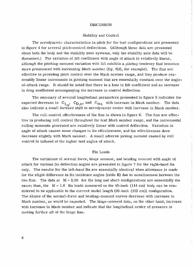
DISCUSSION
Stability and Control
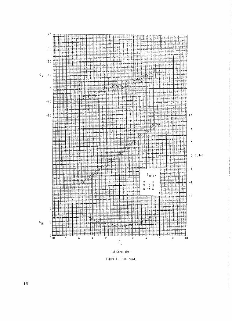
The aerodynamic characteristics i n pitch for the test configurations a r e presented
in figure 4 for several pitch-control deflections. (Although these data a r e presented
about both the body and the stability axes systems, only the stability axis data will be
discussed.) The variation of lift coefficient with angle of attack is relatively l inear,
although the pitching-moment variation with lift exhibits a pitchup tendency that becomes
more pronounced with increasing Mach number (fig. 4(d), for example). The fins a r e
effective i n providing pitch control over the Mach number range, and they produce rea-
sonably linear increments i n pitching moment that a r e essentially constant over the angle-
of-attack range. It should be noted that there is a loss in lift coefficient and an increase
in drag coefficient accompanying the increase in control deflection.
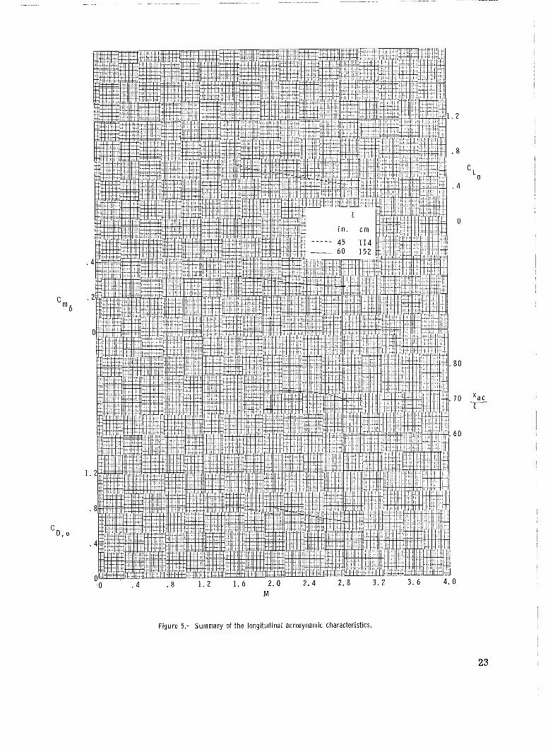
The summary of several longitudinal parameters presented in figure 5 indicates the
expected decrease in C La'
CD,o, and Cm6 with increase in Mach number. The data
also indicate a small forward shift in aerodynamic center with increase in Mach number.
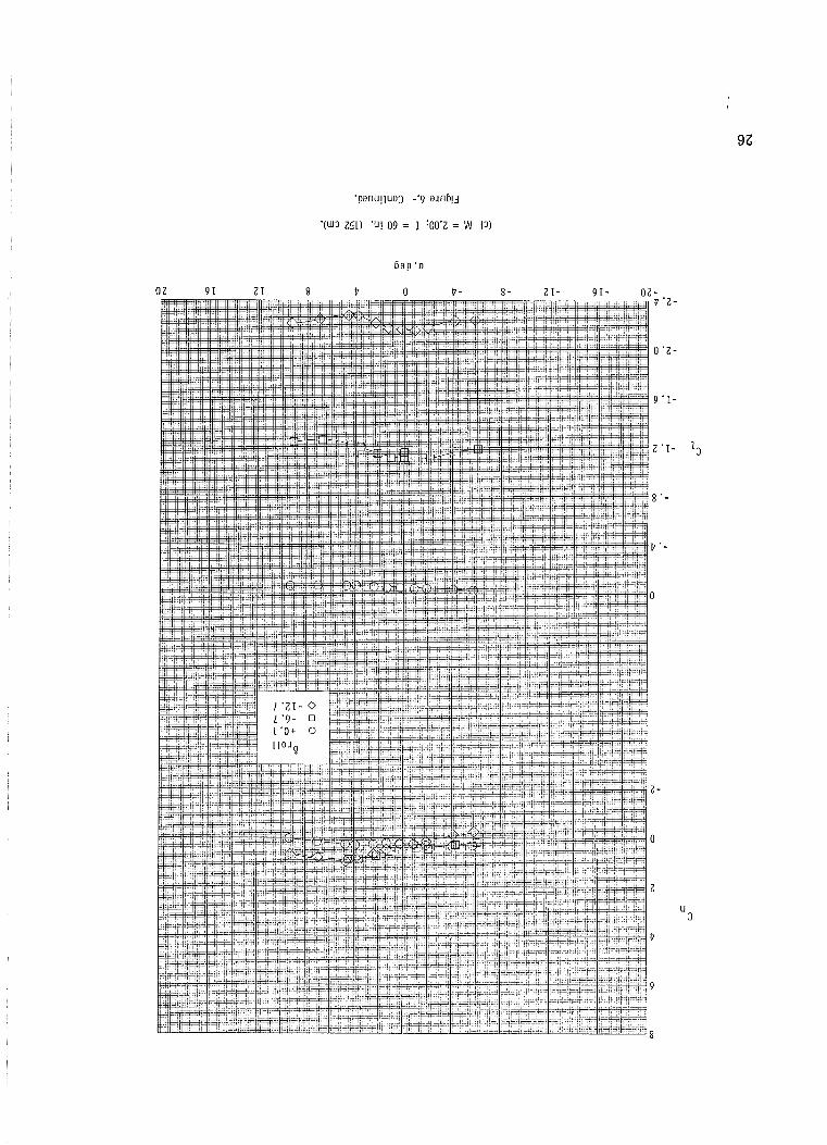
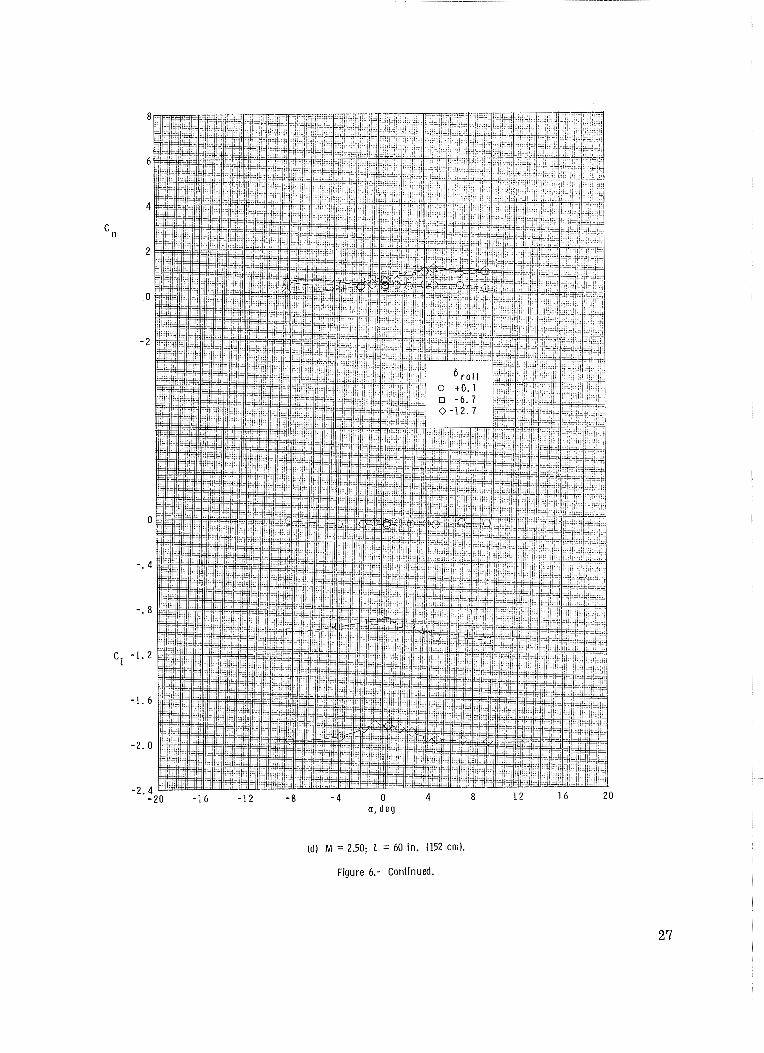
The roll-control effectiveness of the fins is shown in figure 6. The fins a r e effec- tive in producing roll control throughout the tes t Mach number range, and the incremental
rolling moments generated a r e relatively linear with control deflection. Variation in angle of attack causes some changes in fin effectiveness, and the effectiveness does
decrease slightly with Mach number. A small adverse yawing moment caused by rol l
control is induced at the higher tes t angles of attack.
Fin Loads
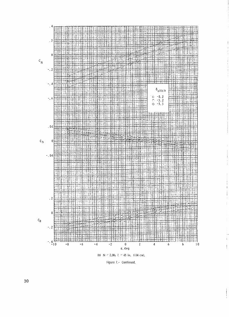
The variations of normal force, hinge moment, and bending moment with angle of
attack for various fin deflection angles a r e presented in figure 7 for the right-hand fin
only. The resul ts for the left-hand fin a r e essentially identical when allowance is made
for the slight difference in fin incidence angles (table 11) due to misalinement between the
two fins. The data at M = 2.00 for the long and short configurations a r e essentially the
same; thus, the M = 1.6 fin loads measured on the 45-inch (114 cm) body can be con-
sidered to be applicable to the correct model length (60-inch (152 cm)) configuration.
The slopes of the normal-force and bending-moment curves decrease with increase in
Mach number, a s would be expected. The hinge-moment data, on the other hand, increase
with increase in Mach number and indicate that the longitudinal center of pressure is
moving further aft of the hinge line.
CONCLUDING REMARKS
Tests of a 0.30-scale model of a n Apache second-stage vehicle, equipped with a coast-phase-control system section having movable cruciform fins,have been made a t
Mach numbers from 1.60 to 2.87.
The resul ts indicated a pitchup tendency that becomes more pronounced with
increasing Mach number. The fins were effective in producing pitch and roll control
throughout the test range of angle of attack and Mach number. At the higher angles of
attack, roll-control deflection induced some adverse yawing moments.
Langley Research Center,
National Aeronautics and Space Administration,
Langley Station, Hampton, Va., October 30, 1969.
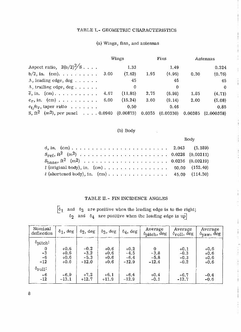
TABLE I.- GEOMETRIC C
(a) Wings, fins, and antennas
Wings
Aspect ratio, 2(b/2)2/S . . . . 1.33 b/2, in. (cm). . . . . . . . . . 3.00 (7.62)
A, leading edge, deg . . . . . . 4 5 A, trailing edge, deg . . . . . . 0 - c , i n . (cm) . . . . . . . . . . . 4.67 (11.85)
cr9 in. (cm) . . . . . . . . . . 6.00 (15.24) ct/cr, taper ra t io . . . . . . . 0.50 S, ft2 (m2), per panel . . . . 0.0940 (0.00873)
Fins
1.49 1.95 (4-95)
4 5
0 2.75 (6.98)
3.60 (9.14)
0.46 0.0355 (0.00330)
Antennas
0.324
0.30 (0.76)
45
0 1.85 (4.71)
2.00 (5.08)
0.85 0.00385 (0.000358)
(b) Body
Body
d, in. (cm) . . . . . . . . . . . . . . . . . . . . . . . . 2.043 (5.189)
Sref, ft2 ("2) . . . , . 0 . . . s 0 . . . 6 . . 6 0.0228 (0.00211)
Sbase, ft2 (m2) . . . . . . . . . . . . . . . , . . . . . 0.0236 (0.00219) I (original body), in. (cm) . . . . . . . . . . . . . . . . 60.00 (152.40)
I (shortened body), in. (cm) . . . . . . . . . . . . . . . 45.00 (1 14.30)
TABLE 1l.- FIN INCIDENCE ANGLES
and 63 a r e positive when the leading edge is to the right; L
62 and 64 a r e positive when the leading edge is u d
Nominal deflection
Gpitch: 0
-3 - 6
'1' deg
~ 0 . 6 +0.6 +0.6
6r011: 1 -:: 1 :::: 1 -:::: - 12 -13.1 +12.7
629 deg
-0.2 -3.2 - 5.3
-1-6.1 +11.9
637 deg
+O. 6 ~ 0 . 6 +O. 6 +0.6
-6.4 -12.9
'49 deg
4-0.2 -4.5 -6.4
-12.9
~ 0 . 4 -0.1
Average Spitch9 deg
0 -3.8 -5.8
-12.4
-6.7 -12.7
-0.4 -0.6
Average 6,,119 deg
+O. 1 -0.3 -0.3 -0.2
Average 6yaw9 deg
~ 0 . 6 +O. 6 +O. 6 +O. 6
A - A C - C I 3
(a) Complete model.
F igure 1.- Sketch of model. A l l l i near d imensions are g iven i n inches and parenthet ical ly i n centimeters.
0 . 0 3 0 r a d .
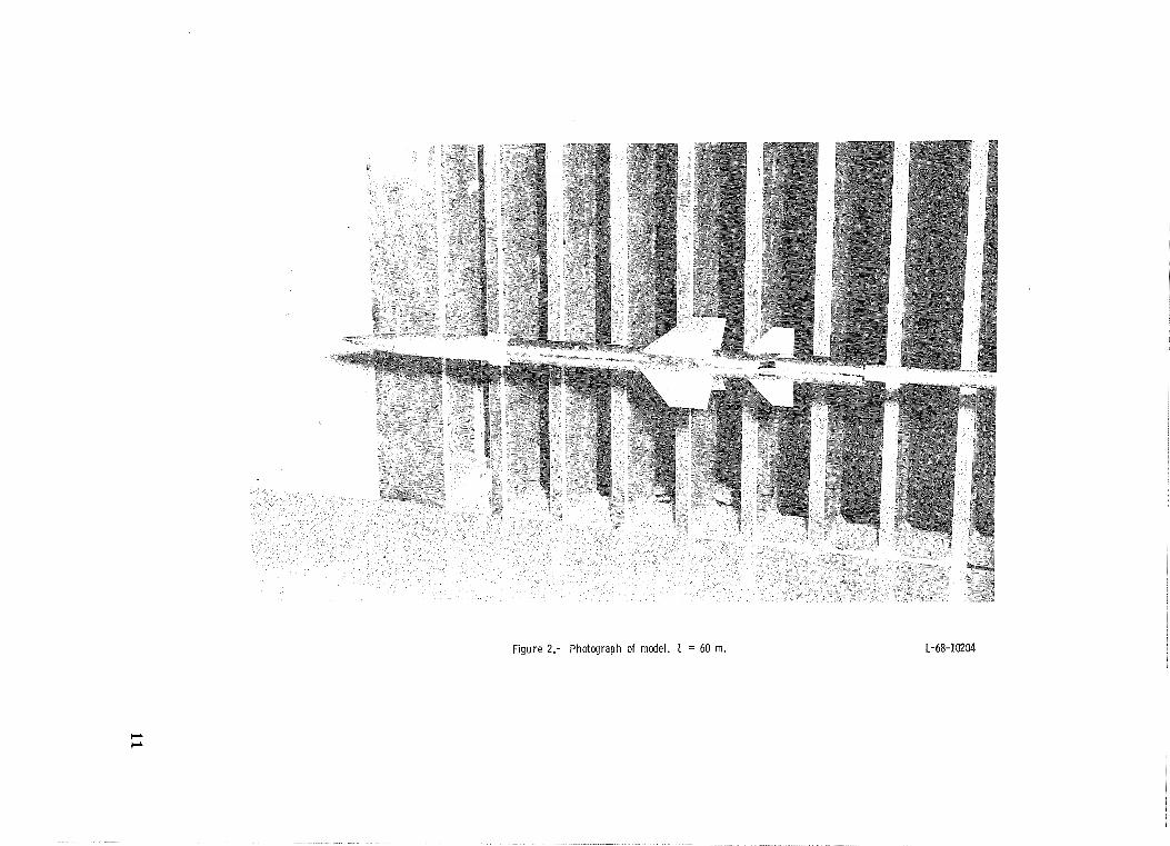
Figure 2.- Photograph of model. 1 = 60 m. L-68-10204
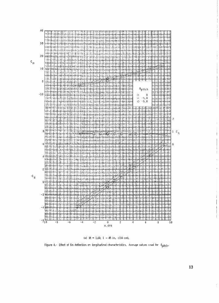
(a) M = 1.60; 1 = 45 in. (114 cm).
Figure 4.- Effect of f i n deflection on longitudinal characteristics. Average values used for 6,,itch.
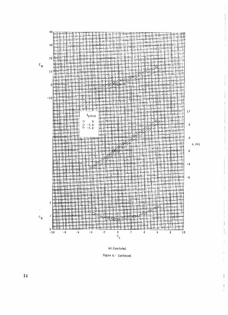
(a) Concluded.
Figure 4.- Continued.
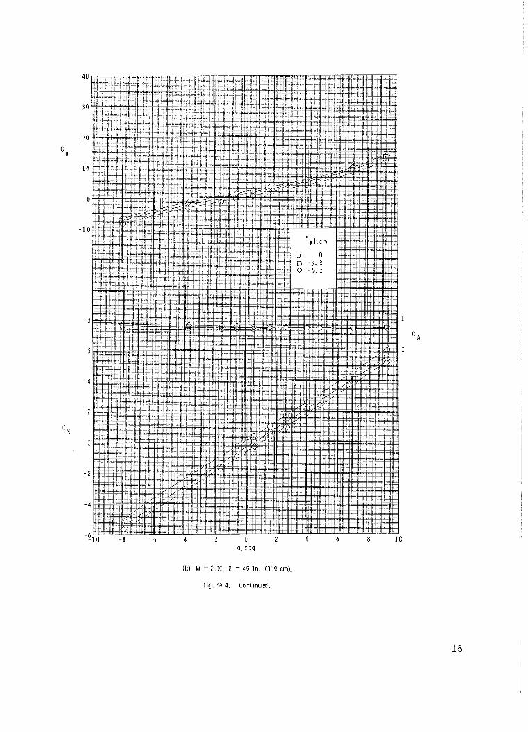
(b) M = 2.00; 1 = 45 in. (114 cm).
Figure 4.- Continued.
L
Ib) Concluded.
Figure 4.- Continued.
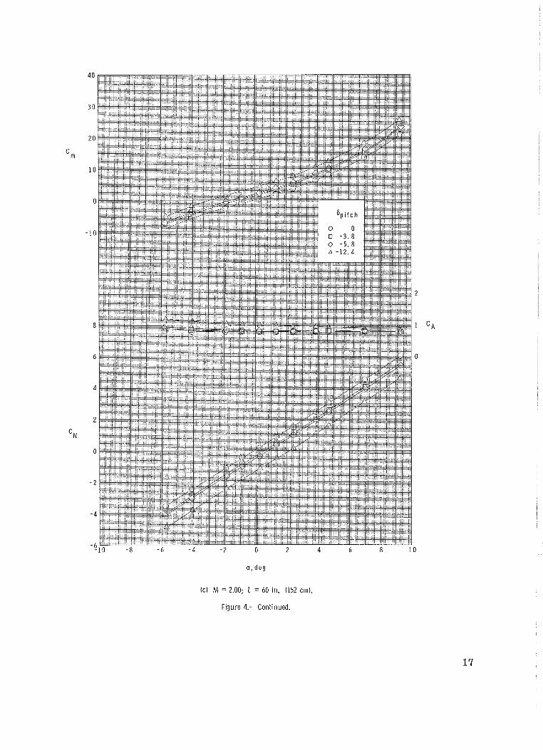
( c ) M = 2.00; Z = 60 in. (152 cm).
Figure 4.- Continued.
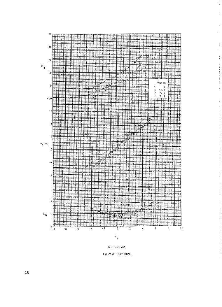
(c) Concluded.
Figure 4.- Continued.
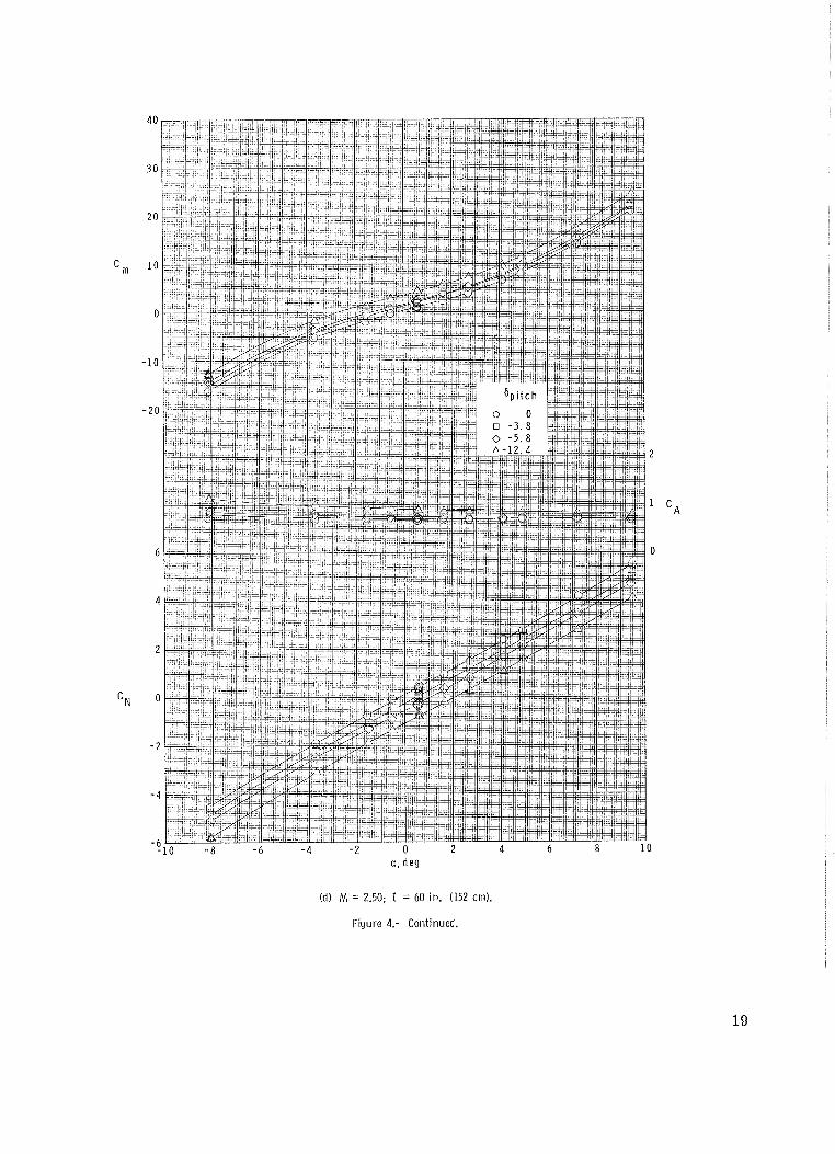
(d) M = 2.50; 2 = 60 in. (152 cm).
Figure 4.- Continued.
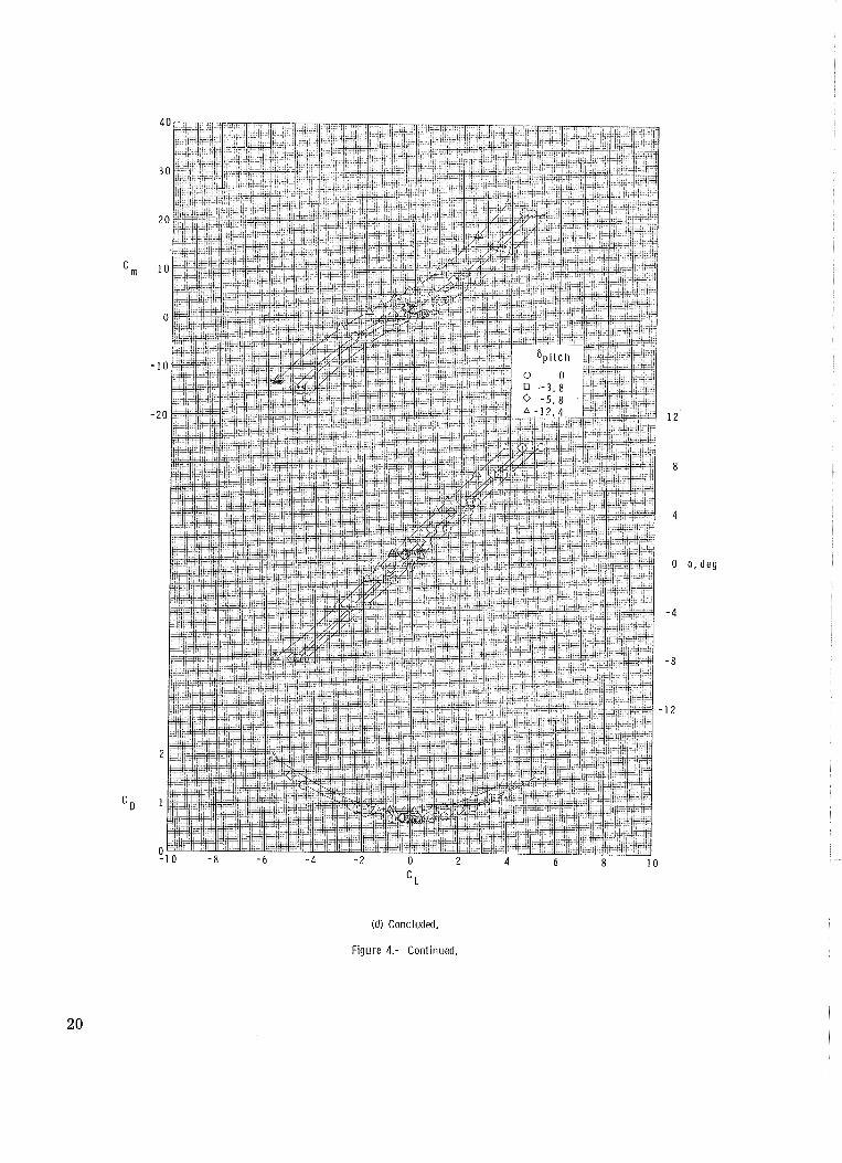
(d) Concluded.
Figure 4.- Continued.
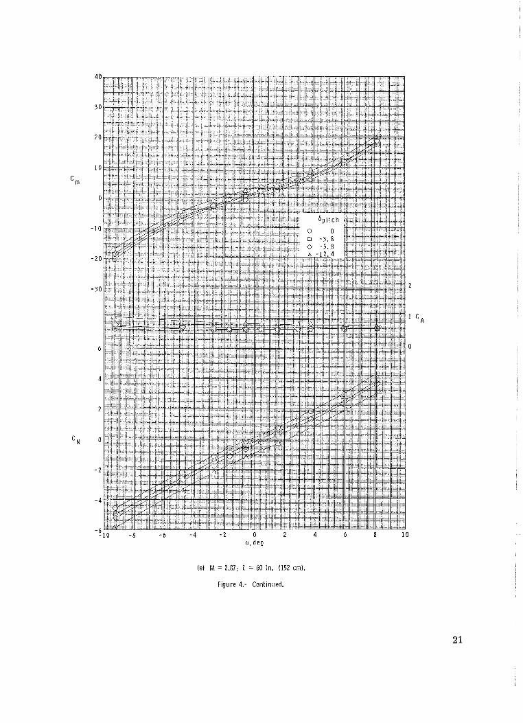
(e) M = 2.87; 1 = 60 in. (152 cm).
Figure 4.- Continued.
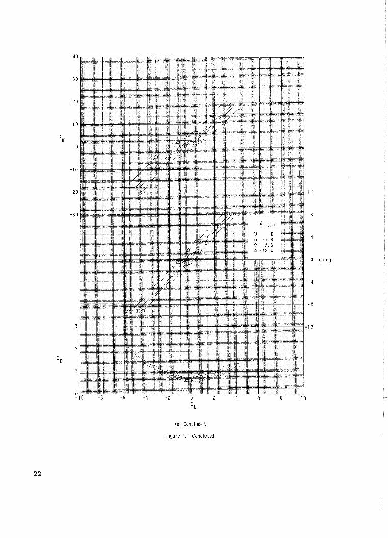
(e) Concluded.
Figure 4.- Concluded.
M
Figure 5.- Summary of the longitudinal aerodynamic characteristics.
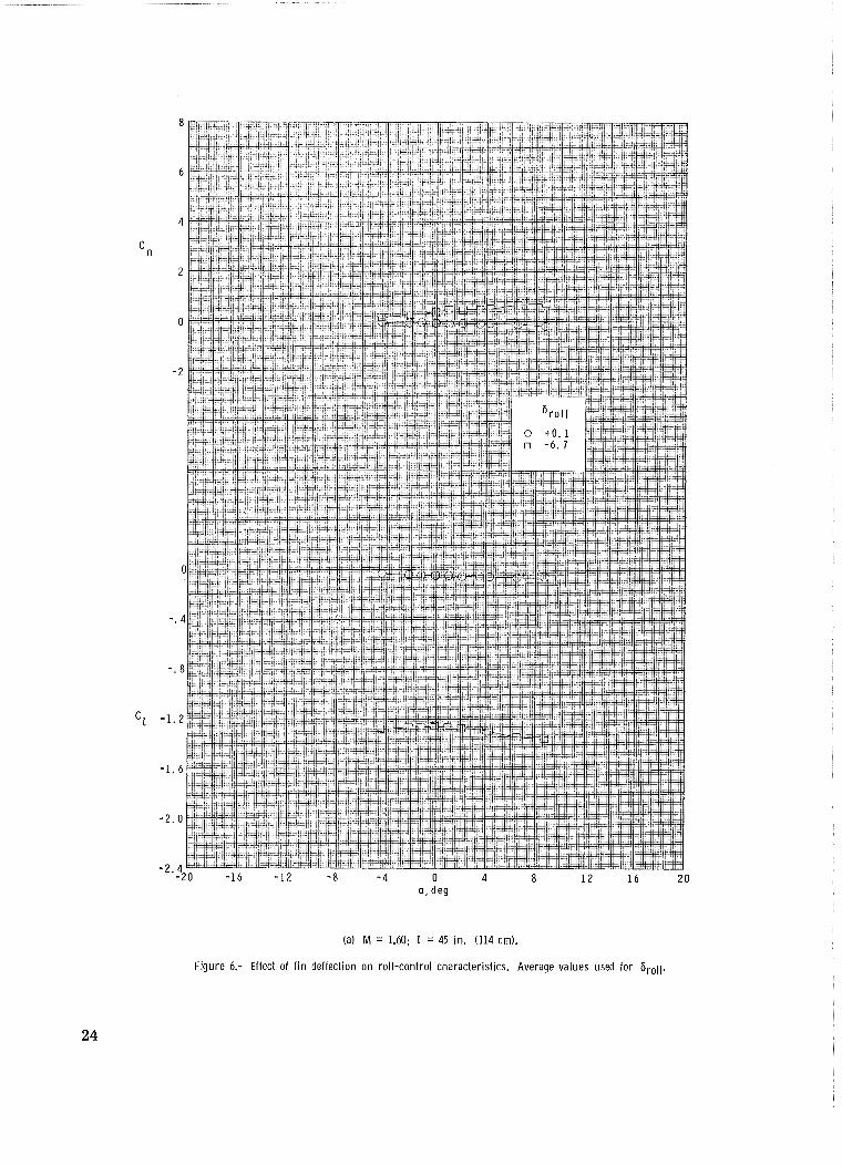
(a) M = 1.60; 1 = 45 in. (114 crn).
Figure 6.- Effect of f i n deflection on roll-control characteristics. Average values used for broil.
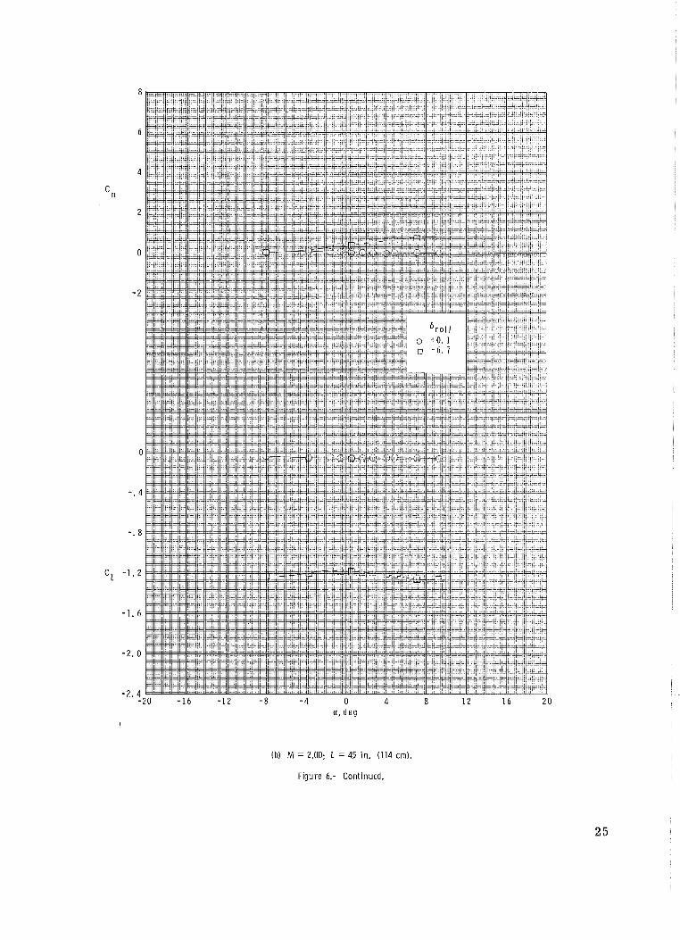
(b) M = 2.00; Z = 45 in. (114 crn).
Figure 6.- Continued.
6 a p ' o
0 Z 9 I Z I 8 b 0 b - 8 - I 91- O Z - ' 2 -
' Z -
' I -
Id) M = 2.50; 1 = 60 in. (152 cm).
Figure 6.- Continued.
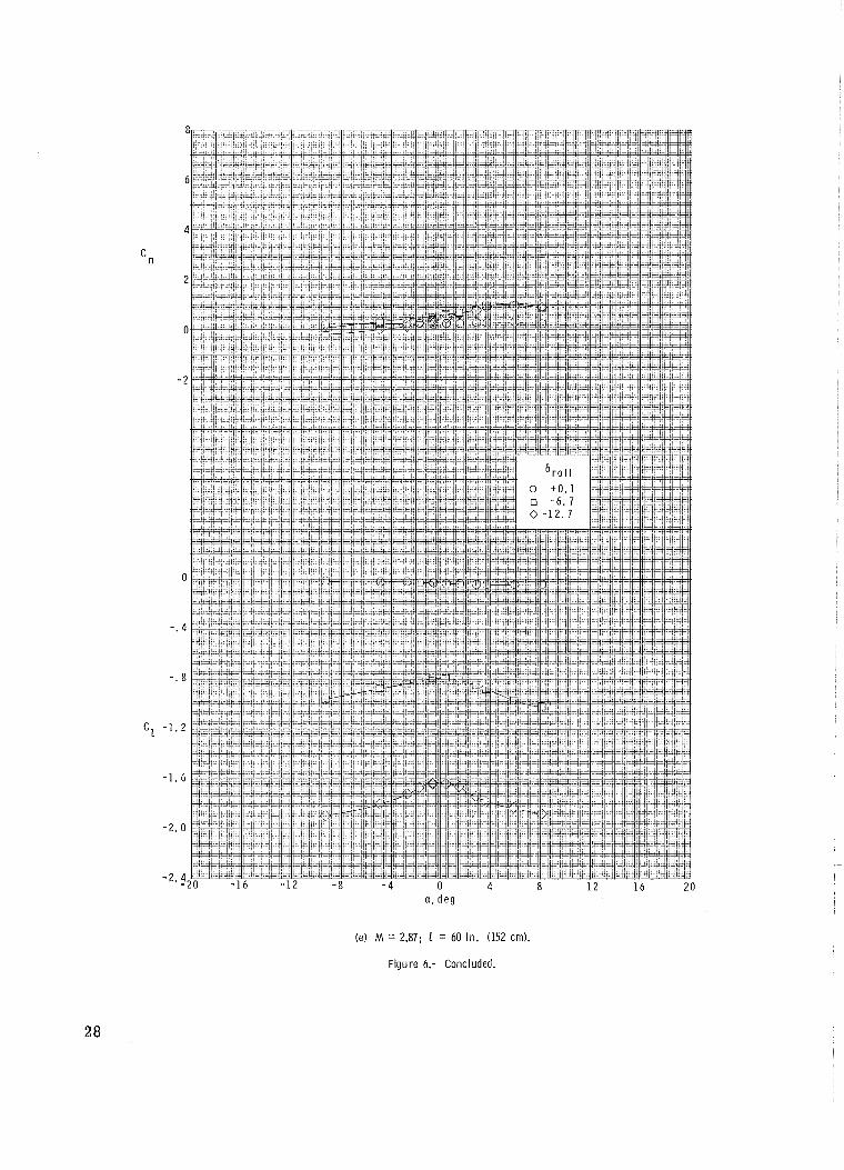
(e) M = 2.87; Z = 60 in. (152 cm).
Figure 6.- Concluded.
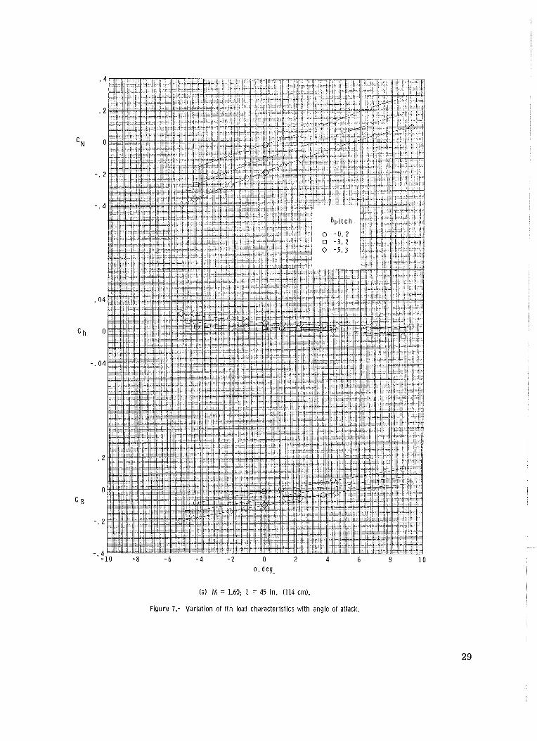
(a) M = 1.60; 1 = 45 in. (114 crn).
Figure 7.- Var iat ion of f i n load character is t ics w i th angle of attack.
a , d e g
(b) M = 2.00; 1 = 45 in. (114 cm).
Figure 7.- Continued.
( c ) M = 2.00; 1 = 60 in. (152 cm).
Figure 7.- Continued.
(dl M = 2.50; 1 = 60 in. (152 em).
Figure 7.- Continued.
(e) M = 2.87; Z = 60 in. (152 cm).
F igure 7.- Concluded.
FIRST CLASS MAIL
P0S"PAGB AMD FEES PA& N A ~ N ~ mmAma AS
SPACE ADMTNTSTXATIOhh
TECHNICAL REPORTS: Scientific and TECHJNICAL TRBNSLATIONS: Information technical information considered importam, published in a foreign language considered complete, and a lasting cantrib~ition to existing to merit NASA distribution in English. knowledge.
SPECIAL PUBLICATIONS: Information TECHNICAL NOTE3 : Informtion less broad in scope but nevertheless of importance as a contribution to existing knowledge.
TlECHNlCAL MEh40mDUMS: Information receiving limited distribution bemuse of preliminary dam, wcurity classifica- tion, or other reasons,
CONTRACTOR REPORTS: Scientific and technical infornution generated under a NASA contract or grant and c~nsidered an important contribution to existing knowledge.
derived from or of value ta NASA activities. Publicatims include conference proceedings, monographs, data compilations, hdbaoks, sourcebooks, and special bibliographies.
TECHNOLOGY UTILIZATION PUBLICATIONS: Infelrmtion an techn~logy used by NASA tlmt may be of particular interest in commercial and other nm-aerospace applicatims. P~lblications include Tech Briefs, Techndogy Utilization Reports and Notes, and Technology Surveys.
Ddetaiis an 6ba availability of these puMicaths may be obtained trm:
SflENTtAC AND TECHNICAL INFOWATION DIVI$ION
NATIONAL AERONAUTICS A N D SPACE ADMtNISTRAFION