versatec specification catalog - waterfurnace.com · requirements for all products, and our...
TRANSCRIPT

Wat
erFu
rnac
e
SP2601 11/05
Design Features
Factory Options
Accessories
Dimensional Data
Physical Data
Performance Data
Engineering Guide Specifications
Water Source/Geothermal Heat Pumps7 thru 10 Ton Horizontal7 thru 23 Ton Vertical
••
Vers
atec
Spe
cific
atio
n C
atal
og

�
VERSATEC SPECIFICATION CATALOG
WaterFurnace Versatec Series products are the units of choice for com-mercial or institutional applications where the best balance of perfor-mance and first cost is desired. Versatec units are available in both a VL group for water source heat pump applications, and a VX group for extended range geothermal applications. Available in 6 vertical sizes (7 through 23 tons) and 3 horizontal sizes (7 through 10 tons), Versatec units provide the user with a great combination of performance, flexibility, op-tions and value.
All Versatec units utilize R-22 refrigerant and PSC blower motors. A standard FX10 microprocessor control is included for flexible integration into facilities with building automation control systems. Vertical units can be ordered in left or right-hand return air configurations with top discharge. Horizontal units are available with left or right-hand return, side or end discharge. Heavy gauge metal cabinets add durability to the system, and can be ordered with durable poly paint for added protection. The wide range of other options makes Versatec models an excellent choice for many types of applications.
Versatec Series products are performance-certified to ARI ISO 13256-1 standards and are ETL listed.
As a leader in the industry, WaterFurnace is dedicated to innovation, quality and customer satisfaction. In fact, every unit built is exposed to a wide range of quality control procedures throughout the assembly process and is then subjected to a rigorous battery of computerized run tests to certify that it meets or exceeds performance standards for efficiency and safety, and will perform flawlessly at startup. As further affirmation of our quality standards, each unit carries our exclusive Quality Assurance emblem, signed by the final test technician.
WaterFurnace International's corporate headquarters and manufacturing facility is located in Fort Wayne, Indiana. A scenic three-acre pond located in front of the building serves as our geothermal heating and cooling source to comfort-condition our 110,000 square feet of manufacturing and office space. As a pioneer, and now a leader in the industry, the team of WaterFurnace engineers, customer support staff and skilled assembly technicians is dedicated to providing the finest com-fort systems available.
By choosing or specifying WaterFurnace Versatec Series products, you can be assured of many years of reliable service and performance at a value-oriented price.

�
VERSATEC SPECIFICATION CATALOG
Table of ContentsARI Data 4
Model Nomenclature 5
Design Features 6-7
Cabinet Configurations 8
Vertical Dimensional Data 9
Horizontal Dimensional Data 10-11
Hanger Assembly 11
Physical Data 12
Control Wiring 12 Electrical Data 13
Fan Performance Data 14
Reference Calculations 15 Correction Factors 15
Legend and Notes 15
Capacity Data 16-24
Engineering Guide Specifications 25-26

�
VERSATEC SPECIFICATION CATALOG
SIZE CFM GPMCOOLING
77° F EWTHEATING
��° F EWT
BTU/HR EER BTU/HR COPHORIZONTAL UNITS
V080 2800 22.0 83,000 14.8 53,600 3.1V095 3200 24.0 95,000 14.2 65,500 3.0V120 4400 28.0 120,000 14.0 98,500 3.2
VERTICAL UNITSV080 2800 22.0 87,000 15.5 56,000 3.2V095 3200 24.0 98,000 15.0 64,500 3.2V120 4000 28.0 122,000 14.0 93,500 3.2V180* 6000 44.0 185,000 17.0 130,000 3.6V240* 8000 56.0 250,000 15.8 194,000 3.5V275* 10,000 70.0 280,000 12.6 220,000 3.3
SIZE CFM GPM COOLING 86° F EWT
HEATING 68° F EWT
BTU/HR EER BTU/HR COPHORIZONTAL UNITS
V080 2800 22.0 77,900 13.1 95,000 4.7V095 3200 24.0 93,000 13.0 114,000 4.6V120 4400 28.0 116,000 12.0 155,000 4.3
VERTICAL UNITSV080 2800 22.0 82,000 14.5 96,000 5.0V095 3200 24.0 93,000 13.3 112,000 4.3V120 4000 28.0 118,000 12.4 158,000 4.3V180* 6000 44.0 179,000 15.9 219,000 5.2V240* 8000 56.0 246,000 14.5 310,000 4.8V275* 10,000 70.0 275,000 11.6 355,000 4.5
ARI DataPerformance Ratings-Water Loop (WLHP)
ISO 13256-1
ISO 13256-1
Performance Ratings-Ground Loop (GLHP)
Notes: Cooling capacitites based on 80.6°F DB, 66.2°F WB entering air temperature.Heating capacities are based on 68°F DB entering air temperature.Models V080, V095, and V120 are rated in accordance with ARI/ISO standard 13256-1: 1988.* Models V180, V240 and V275 ratings are outside the scope of the ARI Water to Air/Brine to Air Heat Pumps Certification Progrram.
Notes: Cooling capacitites based on 80.6°F DB, 66.2°F WB entering air temperature.Heating capacities are based on 68°F DB entering air temperature.Models V080, V095, and V120 are rated in accordance with ARI/ISO standard 13256-1: 1988.* Models V180, V240 and V275 ratings are outside the scope of the ARI Water to Air/Brine to Air Heat Pumps Certification Progrram.

�
VERSATEC SPECIFICATION CATALOG
Model Nomenclature
Model TypeVL = Versatec (Low Temp)VX = Versatec (Ext. Range)
Unit Capacity080 MBTUH095 MBTUH120 MBTUH180 MBTUH240 MBTUH275 MBTUH
Discharge Air ConfigurationT = Top Discharge VerticalE = End Discharge HorizontalS = Side Discharge Horizontal
Return Air ConfigurationL = LeftR= Right
Voltage3 = 208-230/60/34 = 460/60/35 = 575/60/3
Blower Options0 = Standard Blower1 = Oversized Blower Cabinet Options
0 = Painted1 = Nonpainted
Source Coax OptionsC = CopperN = Cupronickel
Sound KitA = NoneB = Blanket
Non-Standard Options Details
VintageC = All
Control Options4 = FX10 (standard - no communication)5 = FX10 w/ Open N2 Com Card6 = FX10 w/ Lonworks Com Card7 = FX10 w/ BacNet Com Card8 = FX10 std. no communication, w/User Interface9 = FX10 w/Open N2 Com Card, w/User Interface0 = FX10 w/Lonworks Com Card, w/User Interface3 = FX10 w/BacNet Com Card, w/User Interface
Non-Standard Options
VL 240 T L 4 0 0 C A 4 S S C

6
VERSATEC SPECIFICATION CATALOG
Versatec 7-23 ton water source heat pumps are de-signed to meet the heating/air conditioning requirements of large zones found in offices, schools, factories, arenas, community centers and other applications. Versatec units 080 to 120 MBTUH are ISO rated and listed for safety through ETL. VX series units are designed to operate with entering water temperatures between 25°F and 110°F for geothermal earth loop applications. VL Series units are designed to operate with entering water temperature between 50°F and 110°F for boiler/tower applications.
Quality and FlexibilityQuality, flexibility, efficiency and performance are major
requirements for all products, and our Versatec line is no exception. Each water source heat pump is factory as-sembled and computer run-tested to ensure reliability. All refrigerant brazing is performed in a nitrogen atmosphere and units are deep evacuated to less than 200 microns prior to refrigerant charging.
Each unit is stretch wrapped to permit visual inspection at the time of delivery. A heavy double-wall corrugated cardboard panel helps protect the air coil from fin damage.
For maximum flexibility, each unit is available in either a left-hand or right-hand air return to provide optimum piping location and service access. Vertical units are only available in top-flow air discharge.
CabinetThe cabinet is constructed of environmentally respon-
sible galvanized steel for maximum corrosion resistance. Service to all internal components is done easily through one or two large removable access panels in the air han-dler compartment and through three panels in the com-pressor compartment. The interiors of the top and side panels and the bottom of the air handling compartment are covered with 1/2-inch thick, 1 1/2-lb. density coated glass fiber. Horizontal units are supplied with hanger brack-ets and grommets to facilitate installation. The standard 2-inch filters are supported by factory mounted brackets which allow side removal.
The water connections are stubbed through the cabinet to allow easy access during installation. Threaded copper adaptors are low-temperatue soldered to prevent misshap-ing or weakening of the fitting, eliminating potential start up leaks.
On horizontal units, the 3/4-inch sweat copper con-densate connection protrudes through the outside of the cabinet for maximum accessibility. On vertical units, the 3/4-inch FPT (1 inch on V180, V240 and V275) copper condensate connection mounts flush to the outside of the cabinet.
The electrical components are located in the compres-sor section of the unit. Three knockouts (of both 7/8-inch
and 1 1/8-inch sizes) are provided on the side and front of the cabinet to facilitate main power and low voltage control wiring through separate holes. All wiring connections are made inside the cabinet for maximum safety. Power wiring is conveniently applied to a single terminal block. Each unit is rated to accept time delay fuses or HACR circuit breakers (USA only) for over-current protection of the branch circuit.
Compressor SectionEach refrigeration system includes hermetic compres-
sors, reversing valves, water-to-refrigerant coaxial heat exchangers, high stability thermostatic expansion valves, air side coils and safety controls. Three panels allow for access to the compressor, coaxial heat exchanger, revers-ing valve and safety controls. High and low pressure ports are provided for easy servicing, and the coaxial heat exchanger and all refrigerant suction lines are insulated to prevent condensation at low entering water temperatures.
Efficient reciprocating, or scroll compressors provide super quiet operation with high reliability. All compressors are isolated from the bottom panel with rubber isolators. The compressor junction box is always located toward the front access panel.
The high stability bidirectional thermostatic expansion valve delivers optimum refrigerant flow over a wide range of conditions and provides bidirectional operation without troublesome check valves. External pressure regulating flow control valves are not recommended, as they tend to compete with the thermal expansion valve.
The reversing valve is "cool-brazed" at the factory to prevent damage from excess heat and is energized in the cooling mode.
The two heat exchangers incorporate the most recent heat transfer technologies. The oversized coaxial heat ex-changers have a convoluted copper (optional cupronickel) inner tube and steel outer tube and are designed for a maximum heat transfer at normal and low water flow rates (down to 1.5 GPM per ton). This minimizes pressure drop and also enhances freeze protection.
The large face air coil consists of rifled copper tubes and lanced aluminum fins to provide high efficiencies at low face velocities and is three rows deep for good mois-ture removal.
Safety controls include a low suction temperature thermistor that is field switchable between well water and antifreeze settings. Low pressure switches (for loss of charge protection) and high pressure switches are de-signed to lock out compressor operation at extreme condi-tions. The low suction temperature thermistor provides the most reliable protection against freeze-up of the coaxial heat exchanger.
Design Features

7
VERSATEC SPECIFICATION CATALOG
Fan SectionThe one or two fan section access panels provide
service access tot he fan motor.The drain pan is epoxy painted for corrosion protec-
tion and is internally trapped inside the cabinet in vertical models. A reliable impedance-type condensate sensor is standard on all units, providing added security especially in ceiling mounted systems.
A belt drive blower system with a single-speed motor is standard on the dual compressor 80 to 120 MBTUH units. 180, 240 and 275 models have twin blower wheels and motors. Fan speed is field adjustable via the drive sheave. All fan/motor assemblies are internally removable to accommodate motor and fan wheel replacement without disconnecting the ductwork. The discharge panel has 1-inch duct flanges allowing adequate material for connect-ing the ductwork.
Control Features The Johnson Controls FX10 board is specifically de-signed for commercial heat pumps and provides control of the entire unit as well as input ports for Open N2, LonTalk, BacNet communication protocols as well as an input port for a user interface. The user interface is an accessory item that can be used to aid in diagnostics and unit setup. A 16 pin low voltage terminal board provides terminals for common field connections. Startup
The unit will not operate until all the inputs and safety controls are checked for normal operating conditions.Fault Retry
All faults are retried twice before finally locking the unit out to prevent nuisance service calls.Component Sequencing Delays
Components are sequenced and delayed for optimum unit performance.Short Cycle Protection and Random Start
The control allows a minimum compressor off time of 4 minutes and a minimum compressor run time of 2 minutes for short cycle protection. A random start delay of 1 to 120 seconds is generated after each power up to prevent simultaneous start-up of all units within a building after the release from an unoccupied cycle or power loss.Emergency Shutdown
A field applied dry contact can be used to place the control into emergency shutdown mode. All outputs on the control board are disabled while the control is in emer-gency shutdown mode.
Design Features (cont.)Condensate Overflow Protection
The board incorporates an impedance liquid sensor at the top of the condensate drain pan. Upon a continuous 30- second sensing of the condensate, the cooling opera-tion of the unit is suspended.Safety Controls
The board receives separate signals from a high pres-sure switch for safety, a low pressure switch to prevent loss of refrigerant charge and a low suction temperature thermistor for freeze protection. Upon a continuous 30-second measurement of the fault (immediate for high pres-sure), compressor operation is stopped.Installation Options
Stand-alone unit controlled by a standard room thermostat.
Stand-alone with a zone temperature sensor. (Must have a user interface to change set points.)Can be integrated into a building automation system by adding a communication module for Open N2, LonTalk, or BacNet.
(For more information on this control, refer to Submittal Data SD1981 or Application Guide AGFX10).
1.
2.

8
VERSATEC SPECIFICATION CATALOG
Cabinet ConfigurationVertical Units
CondensateDrainLocation
Compressors
Blower MotorCoaxial Heat Exchanger
Air CoilTOP VIEW Blower Housing
(Top Discharge)
Water Supply& ReturnConnections
ElectricalControl Box
ElectricalControl Box
Water Supply& ReturnConnections
CondensateDrainLocation
Coaxial Heat Exchanger Blower Motor
Blower Housing(Top Discharge)CompressorsAir Coil TOP VIEW
EndDischargeElectrical
Control Box
SideDischarge
TOP VIEWCoaxial Heat Exchnger
Compressors Blower Motor
Blower Housing
EndDischarge
SideDischarge
ElectricalControl Box
Coaxial Heat ExchngerTOP VIEW
CompressorsBlower Motor
BlowerHousing
* Vertical Left Return Configuration
* Vertical Right Return Configuration
Horizontal Left Return Configuration
Horizontal Right Return Configuration
* Sizes 080-120 Vertical Units Shown. Sizes 180, 240 & 275 include dual blower motors

�
VERSATEC SPECIFICATION CATALOG
Vertical DimensionsV080-V120
UNIT MOUNTS ON A 2.50" RAIL THAT IS NOT INCLUDED IN THE OVERALL HEIGHT DIMENSION.
B
IC
AK
ACCESS
PANEL
ACCESS
PANEL
ACCESSPANELACCESSPANEL
J
H
FRONT
A
B
C
J
K
ACCESS
PANEL
ACCESS
PANEL
ACCESSPANEL
ACCESSPANEL
I
H
N
LM
E
D G
F
FRONT
Vertical DimensionsV180-V275
UNIT MOUNTS ON A 2.50" RAIL THAT IS NOT INCLUDED IN THE OVERALL HEIGHT DIMENSION.
K
A
B
C
J
I
L
K
PANELACCESS
PANEL
ACCESS ACCESS
PANEL
ACCESSPANEL
FRONT
A
B
C
J
I
L
N
M
O
D
E
H
F
G
FRONT
ACCESS
PANEL
ACCESS
PANEL
PANEL
ACCESS
PANEL
ACCESS
MODELCABINET OVERALL
DIMENSIONSBLOWER OPENING
AND LOCATIONDUCT LOCATION
AND DIMENSIONSWATER LINELOCATION
A B C D E F G H I J K L M NV080, V0��
V1�0 34.50 61.32 56.00 21.62 18.07 1.50 16.07 1.75 30.25 1.60 58.13 6.00 11.00 2.07
MODELCABINET OVERALL
DIMENSIONSBLOWER OPENING
AND LOCATIONDUCT LOCATION
AND DIMENSIONSWATER LINELOCATION
A B C D E F G H I J K L M N OV180
V��0/�7� 34.50 88.13 63.96 13.98 18.07 1.50 16.07 24.02 1.68 38.39 1.00 86.13 11.00 6.00 2.07
Notes: Line voltage knockouts are 7/8 inch - All low voltage knockouts are 7/8 inch and 1 1/8 inch Filter rack extends beyond air coil side of cabinet 2 1/8 inch and is removable (includes 1 inch duct flange)
Notes: Line voltage knockouts are 7/8 inch - All low voltage knockouts are 7/8 inch and 1 1/8 inch Filter rack extends beyond air coil side of cabinet 2 1/8 inch and is removable (includes 1 inch duct flange)

10
VERSATEC SPECIFICATION CATALOG
Horizontal Dimensions(See Table on Next Page)
A
LEFT RETURN
B
D
EF
C H
I
Filter Rack
G
K
J
A
B
D
EF
CH
I
Filter Rack
G
K
J
AA
AC
AB
AA
AC
AB
SIDE DISCHARGE
Drain Drain
END DISCHARGE
AAir Coils
B
O
L
M
Y RP
C
QN
AAir Coils
B
O
L
M
YRP
C
QN
AAir Coils
B
OS
W
T
V
P
C
U
Water OutWater In
AAir Coils
B
OS
W
T
V
P
C
U
Water OutWater In
DUCTOPENING
DUCTOPENING
Unit mounts on a 2.50 inch rail that is not included in the overall height dimension
RIGHT RETURN
Front Front

11
VERSATEC SPECIFICATION CATALOG
SIZECABINET OVERALL
DIMENSIONSAIR COIL DIMENSION AND
LOCATIONUNIT MOUNTING
DIMENSIONS
A B C D E F G H I J K L M NV080 34.50 88.13 23.62 35.00 12.06 82.06 3.03 19.04 2.20 3.63 27.24 1.00 94.00 96.00V0�� 34.50 88.13 23.62 35.00 12.06 82.06 3.03 19.04 2.20 3.63 27.24 1.00 94.00 96.00V1�0 34.50 88.13 23.62 40.00 2.06 82.06 3.03 19.04 2.20 3.63 27.24 1.00 94.00 96.00
SIZEBLOWEROPENING
DISCHARGELOCATION
WATER LINELOCATION
DUCTOPENING
O P Q R S T U V W Y AA AB AC ADV080 16.00 13.83 9.00 2.75 2.25 6.15 44.06 6.98 6.00 3.93 2.72 2.06 18.19 84.00V0�� 16.00 13.83 9.00 2.75 2.25 6.15 44.06 6.98 6.00 3.93 2.72 2.06 18.19 84.00V1�0 16.00 13.83 9.00 2.75 2.25 6.15 44.06 6.98 6.00 3.93 2.72 2.06 18.19 84.00
Notes: All water connections are 1 1/4 inch FPT - Condensate connections are 3/4" swt - Low voltage knockouts are 7/8 inch Line voltage knockouts are 1 1/8 inch - Rubber grommets and hanging brackets furnished; need 1/2 inch hanging rod
Horizontal Dimensions (cont.)(Refer to Drawings on Previous Page)
Hanger Assembly(Horizontal Units Only)
Horizontal 7-10 ton units are built with twin 2 1/2-inch high runners under the entire length of the cabinet. Four vibration isolators are included with each horizontal unit for installation as shown.
1/2" Threaded Rod (not included)
Vibration Isolator
Washer(not included)
Hex Nuts(not included)

1�
VERSATEC SPECIFICATION CATALOG
Control Wiring16-Pin Terminal BoardUnits using the FX 10 have three different installation options.
Stand-alone unit controlled by an electronic thermostat.Stand-alone with a zone temperature sensor. A zone temperature sensor is a non-programmable temperature sensor that allows the user to adjust the zone tempera-ture by +/- 5°F. A user interface (Kit # MUIK1) is required to change any zone temperature set points beyond 5 degrees.Integrated into a building automation system by using a zone temperature sensor and adding a communication module for Open N2, LonTalk, or BacNet.
Regardless of which installation option is chosen all low voltage wiring will be done through this terminal board.
1.2.
3.
C
G
LC1
Y2
X1
R
AIC
SC
O
Y1
LC2
L
X2
SS
RS
TO
REV. VALVE
COMPRESSOR1
N/A
LOCKOUT
ACCESSORY
SETPOINT SHIFT
ROOM SENSOR
TEMP OCCUPIED
COMMON
FAN
N/A
COMPRESSOR2
ACCESSORY 1
24VAC
AI COMMON
SENSOR COMMON
R
C
Y1
Y2
O
G
L
24VAC(HOT)
24VAC(COMMON)
COMPRESSOR1
Term
inal
Boa
rdC
onne
ctio
ns ThermostatC
onnections
COMPRESSOR2
REVERSINGVALVE
BLOWERRELAY
SYSTEMMONITOR
Physical DataCOMPONENT
HORIZONTAL VERTICALV080 V0�� V1�0 V080 V0�� V1�0 V180 V��0 V�7�
Fan Wheel Size (in.) 12 x 12 12 x 12 12 x 12 15 x 11 15 x 11 15 x 11 15 x 11 15 x 11 15 x 11# of Fan Motors/# of Blowers 1/1 1/1 1/1 1/1 1/1 1/1 2/2 2/2 2/2
Fan Motor HP (standard) 1.5 2 3 1 1.5 2 1.5 2 3Fan Motor HP (optional) 2 3 3 1.5 2 3 2 3 -
Compressors (�) Recip Recip Scroll Recip Recip Scroll Recip Recip RecipR�� (oz. per circuit) 82 80 102 97 86 106 192 209 215
Water Connection Size (fpt) 1.25” 1.25” 1.25” 1.25” 1.25” 1.25” 2” 2” 2"Condensate Connection 0.75” SWT 0.75” SWT 0.75” SWT 0.75” FPT 0.75” FPT 0.75” FPT 1.0” FPT 1.0” FPT 1.0" FPT
Air Coil Dimensions (in. ea.) 20 x 35 20 x 35 20 x 40 25 x 28 25 x 28 25 x 32 40 x 40 40 x 40 40 x 40Air Coil Face Area x � (sq. ft.) 4.9 4.9 5.6 4.9 4.9 5.6 11.1 11.1 11.1
Air Coil # Rows 3 3 3 3 3 3 3 3 3Filter - �” Throwaway (no.) (3) 20 x 20 (3) 20 x 20 (3) 20 x 20 (2) 28 x 32 (2) 28 x 32 (2) 28 x 32 (2) 40 x 42 (2) 40 x 42 (2) 40 x 42
(1) 20 x 25 (1) 20 x 25 (1) 20 x 25Weight - Packaged 725 737 813 850 900 960 1100 1200 1225
Zone Sensor WiringInstallation options 2 and 3 will use this wiring diagram for the zone temperature sensor.
Electronic Thermostat ConnectionsIf an electronic thermostat is being used, wire as shown in this picture.
SS
RS
AIC
TO
SC
SETPOINTSHIFT
ROOMSENSOR
AICOMMON
Term
inal
Boa
rdC
onne
ctio
ns
ZoneS
ensorConnections
PUSHBUTTON
DICOMMON

1�
VERSATEC SPECIFICATION CATALOG
Electrical Data
SIZE RATEDVOLTAGE
VOLTAGEMIN/MAX
COMPRESSOR* FANMOTORFLA***
FANHP
TOTALUNITFLA
MINCIRCAMP
MAXFUSE
MAXHACR
BREAKERMCC RLA LRA
HO
RIZ
ON
TAL
V080208-230/60/3 197/253 14.0 9.0 70.0 5.6 1.5 23.6 25.9 30 30
460/60/3 414/506 7.1 4.6 33.0 2.8 1.5 12.0 13.2 15 15575/60/3 518/633 5.3 3.4 27.0 2.0 1.5 8.8 9.7 10 10
V080**208-230/60/3 197/253 14.0 9.0 70.0 6.6 2.0 24.6 26.9 35 35
460/60/3 414/506 7.1 4.6 33.0 3.5 2.0 12.7 13.9 15 15575/60/3 518/633 5.3 3.4 27.0 2.4 2.0 9.2 10.1 10 10
V0��208-230/60/3 197/253 16.7 10.7 85.0 6.6 2.0 28.0 30.7 40 40
460/60/3 414/506 8.2 5.3 42.0 3.5 2.0 14.1 15.4 20 20575/60/3 518/633 6.7 4.3 34.0 2.4 2.0 11.0 12.1 15 15
V0��**208-230/60/3 197/253 16.7 10.7 85.0 9.2 3.0 30.6 33.3 40 40
460/60/3 414/506 8.2 5.3 42.0 4.3 3.0 14.9 16.2 20 20575/60/3 518/633 6.7 4.3 34.0 3.6 3.0 12.2 13.3 15 15
V1�0208-230/60/3 197/253 27.0 17.3 123.0 9.2 3.0 43.8 48.1 60 60
460/60/3 414/506 14.0 9.0 62.0 4.3 3.0 22.3 24.6 30 30575/60/3 518/633 11.0 7.1 50.0 3.6 3.0 17.8 19.6 25 25
VER
TIC
AL
V080208-230/60/3 197/253 14.0 9.0 70.0 3.8 1.0 21.8 24.1 30 30
460/60/3 414/506 7.1 4.6 33.0 1.9 1.0 11.1 12.3 15 15575/60/3 518/633 5.3 3.4 27.0 2.0 1.5 8.8 9.7 10 10
V080** 208-230/60/3 197/253 14.0 9.0 70.0 5.6 1.5 23.6 25.9 30 30460/60/3 414/506 7.1 4.6 33.0 2.8 1.5 12.0 13.2 15 15
V0��208-230/60/3 197/253 16.7 10.7 85.0 5.6 1.5 27.0 29.7 40 40
460/60/3 414/506 8.2 5.3 42.0 2.8 1.5 13.4 14.7 20 20575/60/3 518/633 6.7 4.3 34.0 2.0 1.5 10.6 11.7 15 15
V0��**208-230/60/3 197/253 16.7 10.7 85.0 6.6 2.0 28.0 30.7 40 40
460/60/3 414/506 8.2 5.3 42.0 3.5 2.0 14.1 15.4 20 20575/60/3 518/633 6.7 4.3 34.0 2.4 2.0 11.0 12.1 15 15
V1�0208-230/60/3 197/253 27.0 17.3 123.0 6.6 2.0 41.2 45.5 60 60
460/60/3 414/506 14.0 9.0 62.0 3.5 2.0 21.5 23.8 30 30575/60/3 518/633 11.0 7.1 50.0 2.4 2.0 16.6 18.4 25 25
V1�0**208-230/60/3 197/253 27.0 17.3 123.0 9.2 3.0 43.8 48.1 60 60
460/60/3 414/506 14.0 9.0 62.0 4.3 3.0 22.3 24.6 30 30575/60/3 518/633 11.0 7.1 50.0 3.6 3.0 17.8 19.6 25 25
V180208-230/60/3 197/253 29.5 18.9 146.0 5.6 1.5 49.0 53.7 70 70
460/60/3 414/506 14.8 9.5 72.0 2.8 1.5 24.6 26.9 35 35575/60/3 518/633 11.8 7.6 58.0 2.0 1.5 19.1 21.0 25 25
V180**208-230/60/3 197/253 29.5 18.9 146.0 6.6 2.0 51.0 55.7 70 70
460/60/3 414/506 14.8 9.5 72.0 3.5 2.0 26.0 28.3 35 35575/60/3 518/633 11.8 7.6 58.0 2.4 2.0 19.9 21.8 25 25
V��0208-230/60/3 197/253 47.0 30.1 225.0 6.6 2.0 73.5 81.0 110 110
460/60/3 414/506 24.2 15.5 114.0 3.5 2.0 38.0 41.9 50 50575/60/3 518/633 18.9 12.1 80.0 2.4 2.0 29.0 32.1 40 40
V��0**208-230/60/3 197/253 47.0 30.1 225.0 9.2 3.0 78.7 86.2 110 110
460/60/3 414/506 24.2 15.5 114.0 4.3 3.0 39.6 43.5 50 50575/60/3 518/633 18.9 12.1 80.0 3.6 3.0 31.4 34.5 45 45
V�7� 460/60/3 414/506 26.9 17.2 125.0 4.3 3.0 43.2 47.5 60 60
Notes: HACR circuit breaker in USA only. All fuses Class RK-5.* Ratings per each compressor - unit supplied with two.** With optional Motor*** Rating per each motor - V180, V240 and V275 supplied with two.
1�
VERSATEC SPECIFICATION CATALOG
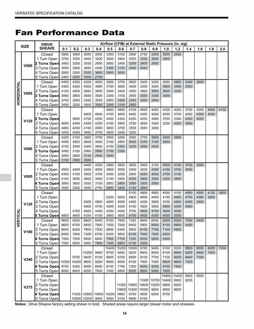
Fan Performance DataSIZE DRIVE
SHEAVEAirflow (CFM) at External Static Pressure (in. wg)
0.1 0.� 0.� 0.� 0.� 0.6 0.7 0.8 0.� 1.0 1.� 1.� 1.6 1.8 �.0
HO
RIZ
ON
TAL
V080
Closed 3900 3800 3650 3500 3300 3100 2950 2750 2450 3050 26501 Turn Open 3700 3550 3400 3200 3000 2800 2550 3200 3000 2800
� Turns Open 3400 3200 3050 2850 2650 2400 3200 2900 26503 Turns Open 3050 2900 3650 2400 3300 3150 2900 26504 Turns Open 2800 2550 3350 3850 2900 26505 Turns Open 2450 3250 3000 2750
V0��
Closed 4450 4350 4200 4050 3900 3750 3600 3400 3250 3050 3800 3450 30001 Turn Open 4350 4200 4050 3990 3750 3600 3400 3200 3000 3900 3400 29502 Turns Open 4150 4000 3950 3650 3500 3400 3200 2900 3850 3600 3250� Turns Open 3900 3800 3650 3500 3300 3100 2900 3500 3300 30004 Turns Open 3700 3550 3350 3050 2900 3400 3200 3000 28005 Turns Open 3450 3250 3000 3500 3300 3100 2850
V1�0
Closed 4900 4800 4700 4600 4450 4300 4000 3700 4550 4400 41501 Turn Open 4900 4800 4700 4600 4450 4300 4200 4000 3700 4550 4300 4050
� Turns Open 4800 4700 4550 4450 4300 4200 4050 3900 3750 3350 4300 40503 Turns Open 4600 4450 4350 4250 4100 3950 3750 3650 3500 3250 4200 39504 Turns Open 4400 4250 4100 4000 3850 3700 3550 3550 32005 Turns Open 4200 4050 3950 3750 3600 3450 3200
VER
TIC
AL
V080
Closed 4225 4100 3900 3700 3500 3250 3000 2700 3600 3400 2900 1 Turn Open 4000 3825 3600 3400 3100 2850 3550 3350 3100 28002 Turns Open 3725 3500 3300 3000 2700 3300 3200 2850 2500� Turns Open 3400 3150 2900 2800 2700 25504 Turns Open 3050 2800 3150 2900 26005 Turns Open 3150 2900 2600
V0��
Closed 4400 4250 3950 3850 3600 3400 3100 4550 4150 3700 3000 1 Turn Open 4550 4400 4200 4000 3800 3550 3300 3000 4350 4150 3700 30002 Turns Open 4300 4100 3900 3700 3450 3200 2900 4250 4000 3700 31003 Turns Open 4100 3850 3600 3400 3150 2900 4000 3800 3500 3200 2850� Turns Open 3800 3600 3350 3150 2850 3800 3550 3300 29505 Turns Open 3550 3300 3050 2750 3600 3400 3150 2800
V1�0
Closed 5100 4900 4800 4550 4100 4900 4500 4150 36501 Turn Open 5200 5000 4800 4600 4400 4150 4950 4700 4360 38502 Turns Open 5000 4800 4650 4500 4400 4200 3950 3700 4850 4450 39003 Turns Open 4900 4700 4500 4350 4150 3900 3600 4800 4450 39504 Turns Open 4700 4600 4400 4200 4000 3700 4900 4700 4600 4050� Turns Open 4800 4600 4350 4100 3900 3600 4700 4500 4300 4050 3500
V180
Closed 9600 9200 8800 8500 8100 7600 7200 6600 6000 9200 8200 7000 54001 Turn Open 9600 8700 8400 7900 7400 7000 6400 5900 8500 8100 6900 54002 Turns Open 8600 8200 7800 7300 6800 6300 5800 8100 7700 7100 58003 Turns Open 8000 7600 7200 6700 6200 5800 8100 7600 7000 6200� Turns Open 7500 7000 6600 6000 7900 7700 7200 6500 5800 54005 Turns Open 7000 6500 5900 7800 7400 6800 6100 5200
V��0
Closed 10400 10200 10000 9700 9400 9100 8300 9900 9000 8200 72001 Turn Open 10200 9900 9700 9400 9200 8900 8500 8100 9900 9200 8400 74002 Turns Open 9700 9400 9100 8900 8700 8400 8100 7700 7100 9200 8400 73003 Turns Open 10300 10000 9600 9200 8900 8500 8100 7600 7000 9600 8600 7500� Turns Open 9700 9300 9000 8500 8100 7700 7200 9500 9200 8700 76005 Turns Open 9000 8600 8200 7800 7400 6800 9200 8800 8400 7800
V�7�
Closed 10900 10400 9900 90001 Turn Open 11000 10700 10400 9900 92002 Turns Open 11200 10900 10600 10250 9900 92003 Turns Open 10600 10300 10000 9800 9600 8600� Turns Open 11200 10900 10600 10250 9900 9700 9500 9200 87005 Turns Open 10500 10200 9900 9500 9100 8900 8700
Notes: Drive Sheave factory setting shown in bold. Shaded areas require larger blower motor and sheaves.

1�
VERSATEC SPECIFICATION CATALOG
Correction Factors
Reference CalculationsHeating Calculations Cooling Calculations
LWT = EWT +
LAT (DB) = EAT (DB) -
LC = TC - SC
S/T =
HRGPM x 500
SCCFM x 1.08
SCTC
LWT = EWT -
LAT = EAT +
TH = HC + HW
HEGPM x 500
HCCFM x 1.08
Legends and Notes
Notes: Capacity data on pages 16-24 does not include water pumping watts and is based upon 15% methanol (by volume) antifreeze solution.For nonstandard airflow conditions, apply the appropriate correction factors found above.Interpolation between EWT, GPM and CFM data is permissible.LAT published is approximate only.Catalog illustrations cover the general appearance of products at time of publication.
AIRFLOWCONNECTION
PERCENT OF RATED* CFM
8�% �0% ��% 100% 10�% 110% 11�%
Total Cooling Capacity 0.972 0.982 0.993 1.000 1.007 1.010 1.013Sensible Cooling Capacity 0.926 0.948 0.974 1.000 1.027 1.055 1.066
KW - Cooling 0.977 0.984 0.993 1.000 1.011 1.018 1.028Total Heat of Rejection 0.975 0.983 0.991 1.000 1.008 1.015 1.018Total Heating Capacity 0.967 0.978 0.990 1.000 1.990 1.017 1.024
KW - Heating 1.009 1.006 1.003 1.000 0.997 0.995 0.993Total Heat of Absorption 0.967 0.976 0.989 1.000 1.010 1.019 1.025
Notes: * Refer to the capacity data on pages 16-24.
CFM = airflow, cubic feet/minuteEWT = entering water temperature, FahrenheitGPM = water flow in gallons/minuteWPD = water pressure drop, PSI and feet of waterEAT = entering air temperature, Fahrenheit (dry bulb/wet bulb)HC = air heating capacity, MBTUHTC = total cooling capacity, MBTUHSC = sensible cooling capacity, MBTUHKW = total power unit input, kilowattsHR = total heat of rejection, MBTUH
HE = total heat of extraction, MBTUHHW = desuperheater capacity, MBTUHEER = Energy Efficient Ratio = BTU output/Watt inputCOP = Coefficient of Performance = BTU output/BTU inputLWT = leaving water temperature, °FLAT = leaving air temperature, °FTH = total heating capacity, MBTUHLC = latent cooling capacity, MBTUHS/T = sensible to total cooling ratio
ABBREVIATIONS AND DEFINITIONS

16
VERSATEC SPECIFICATION CATALOG
EWT GPMWPD COOLING
PSI FT EA TC SC KW HR EER75/63 96.9 69.8 4.01 110.6 24.1
10.0 2.5 5.8 80/67 105.3 72.7 4.10 119.3 25.785/71 113.7 75.6 4.18 128.0 27.275/63 95.1 67.5 3.85 108.2 24.7
�0 16.0 5.4 12.5 80/67 103.4 70.3 3.93 116.8 26.385/71 111.6 73.1 4.00 125.3 27.975/63 94.4 66.8 3.72 107.1 25.4
22.0 7.5 17.3 80/67 102.6 69.6 3.80 115.6 27.085/71 110.9 72.4 3.87 124.1 28.675/63 92.8 67.9 4.51 108.2 20.6
10.0 2.4 5.5 80/67 100.8 70.7 4.60 116.5 21.985/71 108.9 73.5 4.70 124.9 23.275/63 91.7 66.3 4.32 106.4 21.2
60 16.0 5.3 12.3 80/67 99.6 69.0 4.41 114.7 22.685/71 107.6 71.8 4.50 123.0 23.975/63 91.6 66.0 4.19 105.9 21.9
22.0 7.4 17.1 80/67 99.6 68.7 4.3 114.2 23.385/71 107.6 71.5 4.36 122.5 24.775/63 88.7 66.0 5.01 105.8 17.7
10.0 2.4 5.5 80/67 96.4 68.7 5.11 113.9 18.985/71 104.1 71.5 5.21 121.9 20.075/63 88.2 65.1 4.80 104.6 18.4
70 16.0 5.2 12.0 80/67 95.9 67.8 4.90 112.6 19.685/71 103.6 70.5 5.00 120.6 20.775/63 88.8 65.2 4.66 104.7 19.0
22.0 7.3 16.9 80/67 96.5 67.9 4.76 112.8 20.385/71 104.3 70.6 4.85 120.8 21.575/63 80.6 64.0 5.50 99.3 14.7
10.0 2.3 5.3 80/67 87.6 66.7 5.61 106.7 15.685/71 94.6 69.4 5.72 114.1 16.575/63 80.7 63.9 5.28 98.7 15.3
80 16.0 5.1 11.8 80/67 87.7 66.6 5.38 106.1 16.385/71 94.8 69.2 5.49 113.5 17.375/63 81.8 64.3 5.14 99.3 15.9
22.0 6.9 15.9 80/67 88.9 67.0 5.24 106.8 17.085/71 96.0 69.7 5.35 114.3 18.075/63 76.6 63.1 5.75 96.2 13.3
10.0 2.3 5.3 80/67 83.2 65.7 5.86 103.3 14.285/71 89.9 68.3 5.98 110.3 15.075/63 77.0 63.3 5.51 95.8 14.0
8� 16.0 5.1 11.8 80/67 83.7 65.9 5.63 102.9 14.985/71 90.4 68.6 5.74 110.0 15.875/63 78.3 63.9 5.37 96.6 14.6
22.0 6.5 15.0 80/67 85.1 66.6 5.5 103.8 15.585/71 91.9 69.2 5.59 111.0 16.475/63 72.6 62.1 5.99 93.1 12.1
10.0 2.3 5.3 80/67 79.0 64.7 6.11 99.8 12.985/71 85.3 67.3 6.24 106.6 13.775/63 73.3 62.7 5.75 92.9 12.7
�0 16.0 5.0 11.6 80/67 79.7 65.3 5.87 99.7 13.685/71 86.0 67.9 5.98 106.4 14.475/63 74.8 63.5 5.61 93.9 13.3
22.0 6.0 13.9 80/67 81.3 66.1 5.72 100.8 14.285/71 87.8 68.8 5.84 107.7 15.075/63 67.2 58.3 6.38 89.0 10.5
10.0 2.2 5.1 80/67 73.1 60.7 6.51 95.3 11.285/71 78.9 63.1 6.64 101.6 11.975/63 68.3 59.4 6.13 89.2 11.1
100 16.0 5.0 11.6 80/67 74.2 61.9 6.25 95.6 11.985/71 80.2 64.4 6.38 102.0 12.675/63 70.2 60.5 5.99 90.6 11.7
22.0 5.8 13.4 80/67 76.3 63.0 6.11 97.1 12.585/71 82.4 65.6 6.24 103.7 13.275/63 61.9 54.5 6.77 85.0 9.1
10.0 2.2 5.2 80/67 67.3 56.7 6.91 90.9 9.785/71 72.7 59.0 7.05 96.8 10.375/63 63.4 56.2 6.50 85.6 9.7
110 16.0 4.9 11.3 80/67 68.9 58.6 6.64 91.6 10.485/71 74.4 60.9 6.77 97.5 11.075/63 65.6 57.6 6.37 87.3 10.3
22.0 5.8 13.4 80/67 71.3 60.0 6.50 93.5 11.085/71 77.0 62.4 6.63 99.6 11.6
EWT GPMWPD HEATING
PSI FT EA HC KW HE LAT COP60.0 56.7 4.25 42.1 78.7 3.90
10.0 2.6 6.0 70.0 54.3 4.48 39.0 88.0 3.5580.0 51.9 4.70 35.9 97.2 3.2460.0 58.0 4.31 43.3 79.2 3.95
�0 16.0 5.6 13.0 70.0 55.6 4.54 40.1 88.4 3.5980.0 53.2 4.76 36.9 97.6 3.2760.0 60.0 4.31 45.2 79.8 4.07
22.0 7.9 18.3 70.0 57.4 4.54 41.9 89.0 3.7080.0 54.8 4.77 38.5 98.1 3.3760.0 66.8 4.56 51.2 82.1 4.29
10.0 2.5 5.7 70.0 64.0 4.80 47.6 91.2 3.9180.0 61.3 5.04 44.1 100.3 3.5660.0 68.5 4.62 52.8 82.7 4.35
�0 16.0 5.4 12.4 70.0 65.7 4.86 49.1 91.7 3.9680.0 62.8 5.11 45.4 100.8 3.6060.0 70.6 4.64 54.8 83.3 4.46
22.0 7.8 18.0 70.0 67.8 4.88 51.2 92.4 4.0780.0 64.8 5.13 47.3 101.4 3.7160.0 76.8 4.86 60.2 85.4 4.63
10.0 2.5 5.8 70.0 73.7 5.12 56.3 94.4 4.2280.0 70.7 5.38 52.3 103.4 3.8560.0 79.0 4.93 62.2 86.1 4.69
�0 16.0 5.4 12.5 70.0 75.8 5.19 58.1 95.1 4.2880.0 72.6 5.45 54.0 104.0 3.9060.0 81.6 4.96 64.7 87.0 4.82
22.0 7.5 17.3 70.0 78.3 5.23 60.5 95.9 4.3980.0 75.0 5.49 56.2 104.8 4.0060.0 87.8 5.10 70.4 89.0 5.04
10.0 2.4 5.5 70.0 84.4 5.37 66.1 97.9 4.6180.0 81.0 5.64 61.8 106.8 4.2160.0 90.4 5.17 72.8 89.9 5.12
60 16.0 5.3 12.3 70.0 86.9 5.45 68.3 98.7 4.6880.0 83.4 5.72 63.9 107.6 4.2760.0 93.5 5.22 75.7 90.9 5.24
22.0 7.4 17.1 70.0 89.8 5.50 71.0 99.7 4.7980.0 86.1 5.77 66.4 108.5 4.3760.0 98.8 5.34 80.6 92.7 5.43
10.0 2.4 5.5 70.0 95.2 5.62 76.1 101.5 4.9780.0 91.6 5.90 71.5 110.3 4.5560.0 101.8 5.42 83.3 93.7 5.51
70 16.0 5.2 12.0 70.0 98.1 5.70 78.6 102.4 5.0480.0 94.3 5.99 73.9 111.2 4.6260.0 105.2 5.48 86.5 94.8 5.62
22.0 7.3 16.9 70.0 101.3 5.77 81.6 103.5 5.1480.0 97.4 6.06 76.7 112.2 4.7160.0 111.3 5.66 92.0 96.8 5.76
10.0 2.3 5.3 70.0 107.5 5.95 87.2 105.6 5.2980.0 103.7 6.25 82.4 114.3 4.8660.0 115.0 5.74 95.4 98.0 5.86
80 16.0 5.1 11.8 70.0 111.0 6.05 90.4 106.7 5.3880.0 107.1 6.35 85.4 115.4 4.9460.0 118.8 5.83 98.9 99.3 5.97
22.0 6.9 15.9 70.0 114.6 6.14 93.7 107.9 5.4780.0 110.5 6.44 88.5 116.6 5.0360.0 123.8 5.98 103.4 100.9 6.07
10.0 2.3 5.3 70.0 119.9 6.29 98.4 109.7 5.5980.0 116.1 6.60 93.5 118.4 5.1560.0 128.0 6.07 107.3 102.3 6.18
�0 16.0 5.0 11.6 70.0 124.0 6.39 102.2 111.0 5.6980.0 120.0 6.71 97.1 119.7 5.2460.0 132.2 6.18 111.1 103.7 6.27
22.0 6.0 13.9 70.0 128.0 6.50 105.8 112.3 5.7780.0 123.8 6.83 100.5 120.9 5.31
V080 - VerticalCooling Capacity Data (2800 CFM) Heating Capacity Data (2800 CFM)
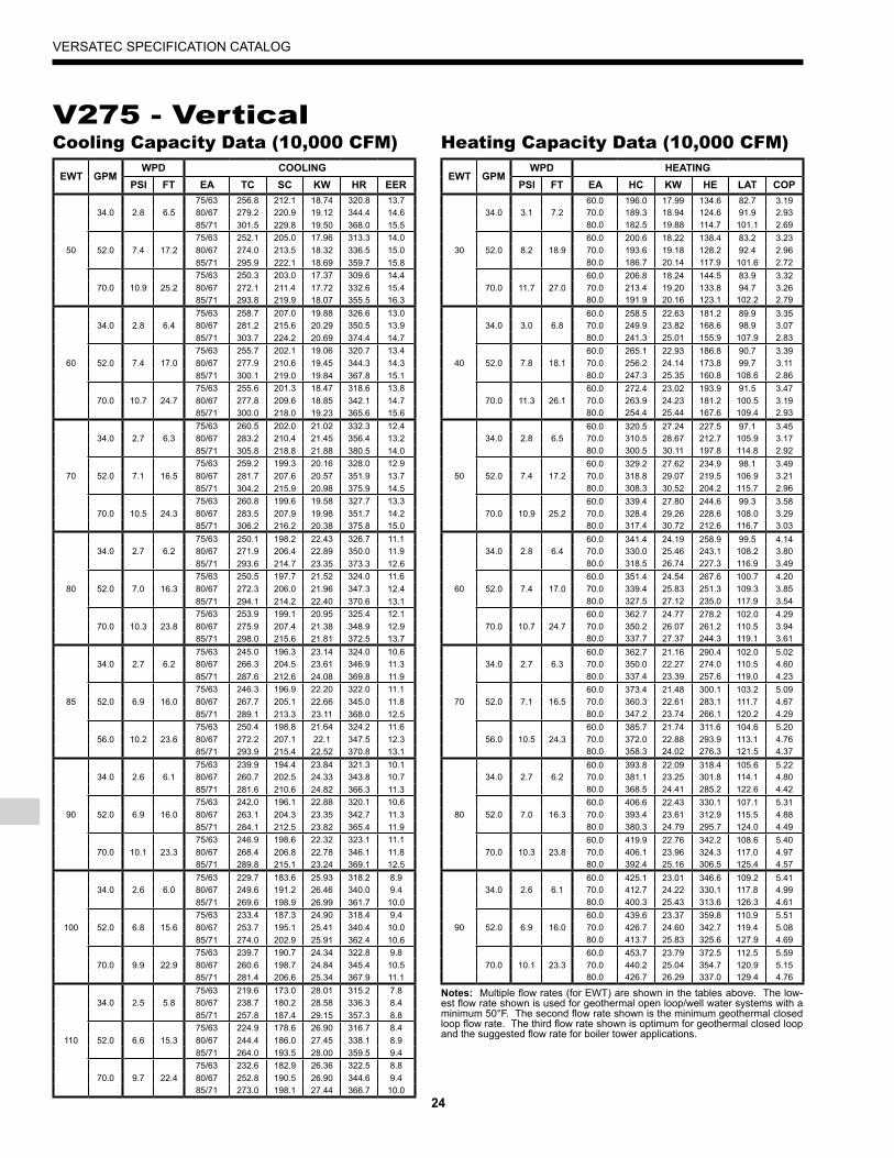
Notes: Multiple flow rates (for EWT) are shown in the tables above. The low-est flow rate shown is used for geothermal open loop/well water systems with a minimum 50°F. The second flow rate shown is the minimum geothermal closed loop flow rate. The third flow rate shown is optimum for geothermal closed loop and the suggested flow rate for boiler tower applications.

17
VERSATEC SPECIFICATION CATALOG
EWT GPMWPD COOLING
PSI FT EA TC SC KW HR EER75/63 86.2 65.1 4.60 101.9 18.8
10.0 2.5 5.8 80/67 93.7 67.8 4.69 109.7 20.085/71 101.2 70.5 4.78 117.5 21.275/63 86.0 63.7 4.36 100.9 19.8
�0 16.0 5.4 12.5 80/67 93.5 66.4 4.45 108.7 21.085/71 101.0 69.0 4.53 116.5 22.375/63 83.7 63.2 4.22 98.1 19.9
22.0 7.5 17.3 80/67 91.0 65.9 4.30 105.7 21.185/71 98.3 68.5 4.39 113.2 22.475/63 87.5 66.9 4.73 103.7 18.5
10.0 2.4 5.5 80/67 95.1 69.7 4.83 111.6 19.785/71 102.7 72.5 4.93 119.6 20.875/63 88.1 66.1 4.50 103.4 19.6
60 16.0 5.3 12.2 80/67 95.7 68.9 4.59 111.4 20.885/71 103.4 71.6 4.69 119.4 22.175/63 86.5 66.0 4.37 101.5 19.8
22.0 7.4 17.0 80/67 94.1 68.7 4.46 109.3 21.185/71 101.6 71.5 4.55 117.1 22.375/63 81.9 63.1 5.49 100.6 14.9
10.0 2.4 5.4 80/67 89.0 65.7 5.60 108.1 15.985/71 96.1 68.3 5.71 115.6 16.875/63 83.1 63.0 5.24 101.0 15.9
70 16.0 5.2 11.9 80/67 90.3 65.6 5.34 108.6 16.985/71 97.6 68.2 5.45 116.2 17.975/63 82.5 63.2 5.10 99.9 16.2
22.0 7.1 16.4 80/67 89.7 65.9 5.21 107.5 17.285/71 96.9 68.5 5.31 115.0 18.275/63 75.1 60.1 5.92 95.3 12.7
10.0 2.3 5.4 80/67 81.6 62.6 6.04 102.2 13.585/71 88.2 65.1 6.16 109.2 14.375/63 76.9 60.6 5.66 96.2 13.6
80 16.0 5.1 11.8 80/67 83.6 63.1 5.78 103.3 14.585/71 90.2 65.7 5.89 110.4 15.375/63 77.1 61.2 5.54 96.0 13.9
22.0 6.9 16.0 80/67 83.8 63.7 5.65 103.1 14.885/71 90.5 66.3 5.77 110.2 15.775/63 73.4 55.9 6.15 94.4 11.9
10.0 2.3 5.4 80/67 79.8 58.2 6.28 101.2 12.785/71 86.2 60.6 6.40 108.0 13.575/63 75.5 56.7 5.90 95.6 12.8
8� 16.0 5.1 11.8 80/67 82.1 59.1 6.02 102.6 13.685/71 88.6 61.4 6.14 109.6 14.475/63 76.1 57.4 5.78 95.8 13.2
22.0 6.5 15.0 80/67 82.7 59.8 5.90 102.9 14.085/71 89.3 62.2 6.02 109.9 14.875/63 68.6 56.7 6.40 90.5 10.7
10.0 2.3 5.3 80/67 74.6 59.1 6.53 96.9 11.485/71 80.6 61.4 6.66 103.3 12.175/63 70.9 57.8 6.14 91.9 11.5
�0 16.0 5.0 11.6 80/67 77.0 60.3 6.27 98.4 12.385/71 83.2 62.7 6.40 105.0 13.075/63 71.8 58.7 6.04 92.4 11.9
22.0 6.0 13.7 80/67 78.1 61.2 6.16 99.1 12.785/71 84.3 63.6 6.28 105.7 13.475/63 62.4 53.0 6.78 85.5 9.2
10.0 2.2 5.1 80/67 67.8 55.2 6.92 91.4 9.885/71 73.2 57.4 7.06 97.3 10.475/63 65.0 54.6 6.53 87.3 10.0
100 16.0 5.0 11.6 80/67 70.7 56.9 6.67 93.4 10.685/71 76.3 59.2 6.80 99.5 11.275/63 66.6 55.8 6.44 88.5 10.3
22.0 5.8 13.4 80/67 72.4 58.1 6.57 94.8 11.085/71 78.1 60.4 6.70 101.0 11.775/63 57.9 49.8 7.17 82.4 8.1
10.0 2.2 5.1 80/67 62.9 51.9 7.32 87.9 8.685/71 68.0 53.9 7.46 93.4 9.175/63 60.9 51.9 6.94 84.6 8.8
110 16.0 4.9 11.2 80/67 66.2 54.1 7.08 90.4 9.485/71 71.5 56.2 7.22 96.2 9.975/63 63.0 53.3 6.86 86.5 9.2
22.0 5.8 13.3 80/67 68.5 55.5 7.00 92.4 9.885/71 74.0 57.8 7.14 98.4 10.4
EWT GPMWPD HEATING
PSI FT EA HC KW HE LAT COP60.0 55.4 4.45 40.2 78.3 3.65
10.0 2.6 6.0 70.0 53.3 4.69 37.3 87.6 3.3380.0 51.1 4.92 34.3 96.9 3.0460.0 56.9 4.51 41.5 78.8 3.70
�0 16.0 5.6 12.9 70.0 54.6 4.75 38.4 88.1 3.3780.0 52.4 4.98 35.4 97.3 3.0860.0 59.0 4.58 43.4 79.5 3.78
22.0 7.9 18.3 70.0 56.6 4.82 40.1 88.7 3.4480.0 54.2 5.06 36.9 97.9 3.1460.0 67.3 4.77 51.0 82.2 4.14
10.0 2.5 5.8 70.0 64.6 5.02 47.4 91.3 3.7780.0 61.8 5.27 43.9 100.5 3.4460.0 68.5 4.85 52.0 82.6 4.14
�0 16.0 5.4 12.5 70.0 65.7 5.10 48.3 91.7 3.7880.0 63.0 5.36 44.7 100.8 3.4560.0 70.6 4.91 53.9 83.4 4.21
22.0 7.8 18.0 70.0 68.0 5.17 50.4 92.5 3.8580.0 65.1 5.43 46.6 101.5 3.5160.0 77.8 5.05 60.5 85.7 4.51
10.0 2.5 5.8 70.0 74.7 5.32 56.6 94.7 4.1280.0 71.7 5.59 52.6 103.7 3.7660.0 79.5 5.16 61.9 86.3 4.51
�0 16.0 5.4 12.5 70.0 76.4 5.43 57.8 95.2 4.1280.0 73.2 5.70 53.8 104.2 3.7660.0 82.1 5.23 64.3 87.2 4.60
22.0 7.5 17.3 70.0 78.8 5.50 60.1 96.1 4.2080.0 75.6 5.78 55.9 105.0 3.8360.0 89.3 5.22 71.5 89.5 5.01
10.0 2.4 5.5 70.0 85.9 5.49 67.1 98.4 4.5880.0 82.5 5.77 62.8 107.3 4.1960.0 91.5 5.35 73.3 90.3 5.01
60 16.0 5.3 12.2 70.0 88.0 5.63 68.8 99.1 4.5880.0 84.5 5.91 64.3 107.9 4.1960.0 94.4 5.41 75.9 91.2 5.11
22.0 7.4 17.0 70.0 90.7 5.70 71.3 100.0 4.6780.0 87.0 5.98 66.6 108.8 4.2660.0 97.9 5.48 79.2 92.4 5.24
10.0 2.4 5.4 70.0 94.4 5.77 74.7 101.2 4.8080.0 90.9 6.05 70.3 110.1 4.4060.0 103.5 5.64 84.3 94.2 5.38
70 16.0 5.2 11.9 70.0 99.8 5.93 79.5 103.0 4.9380.0 96.0 6.23 74.7 111.7 4.5160.0 106.5 5.70 87.1 95.2 5.48
22.0 7.1 16.3 70.0 102.6 6.00 82.1 103.9 5.0180.0 98.7 6.30 77.2 112.6 4.5960.0 113.7 5.82 93.9 97.6 5.73
10.0 2.3 5.4 70.0 109.9 6.12 89.0 106.3 5.2680.0 106.0 6.43 84.1 115.1 4.8360.0 117.3 6.01 96.7 98.8 5.72
80 16.0 5.1 11.8 70.0 113.3 6.33 91.7 107.5 5.2580.0 109.3 6.64 86.7 116.2 4.8260.0 120.4 6.07 99.7 99.8 5.81
22.0 6.9 16.0 70.0 116.3 6.39 94.5 108.5 5.3380.0 112.2 6.71 89.3 117.1 4.9060.0 126.2 6.14 105.3 101.7 6.02
10.0 2.3 5.3 70.0 122.3 6.46 100.3 110.5 5.5580.0 118.4 6.79 95.3 119.2 5.1160.0 130.5 6.37 108.8 103.2 6.00
�0 16.0 5.0 11.6 70.0 126.5 6.71 103.6 111.8 5.5380.0 122.4 7.04 98.4 120.5 5.1060.0 133.7 6.42 111.8 104.2 6.10
22.0 6.0 13.7 70.0 129.5 6.76 106.4 112.8 5.6180.0 125.3 7.10 101.1 121.5 5.17
V080 - HorizontalCooling Capacity Data (2800 CFM) Heating Capacity Data (2800 CFM)
Notes: Multiple flow rates (for EWT) are shown in the tables above. The low-est flow rate shown is used for geothermal open loop/well water systems with a minimum 50°F. The second flow rate shown is the minimum geothermal closed loop flow rate. The third flow rate shown is optimum for geothermal closed loop and the suggested flow rate for boiler tower applications.

18
VERSATEC SPECIFICATION CATALOG
EWT GPMWPD COOLING
PSI FT EA TC SC KW HR EER75/63 106.0 77.2 5.41 124.5 19.6
12.0 2.2 5.1 80/67 115.2 80.4 5.52 134.1 20.985/71 124.5 83.6 5.63 143.7 22.175/63 103.6 73.1 5.12 121.1 20.2
�0 18.0 5.0 11.7 80/67 112.7 76.2 5.23 130.5 21.685/71 121.7 79.2 5.33 139.9 22.875/63 100.8 72.5 4.96 117.7 20.3
24.0 8.6 19.9 80/67 109.6 75.6 5.06 126.8 21.685/71 118.3 78.6 5.16 135.9 22.975/63 101.9 74.6 5.91 122.1 17.2
12.0 2.2 5.0 80/67 110.7 77.7 6.03 131.3 18.485/71 119.6 80.8 6.15 140.6 19.475/63 100.7 72.8 5.67 120.0 17.8
60 18.0 4.9 11.3 80/67 109.4 75.9 5.78 129.2 18.985/71 118.2 78.9 5.90 138.3 20.075/63 100.6 72.5 5.49 119.4 18.3
24.0 8.4 19.4 80/67 109.4 75.5 5.61 128.5 19.585/71 118.1 78.6 5.72 137.7 20.775/63 100.5 72.7 6.50 122.6 15.5
12.0 2.4 5.5 80/67 109.2 75.7 6.63 131.8 16.585/71 117.9 78.7 6.77 141.0 17.475/63 101.4 71.9 6.19 122.6 16.4
70 18.0 5.2 12.0 80/67 110.3 74.9 6.31 131.8 17.585/71 119.1 77.9 6.44 141.1 18.575/63 100.5 72.5 6.03 121.1 16.7
24.0 8.2 18.9 80/67 109.2 75.5 6.15 130.2 17.885/71 118.0 78.5 6.27 139.4 18.875/63 91.0 72.5 7.00 114.9 13.0
12.0 2.3 5.3 80/67 98.9 75.5 7.14 123.3 13.885/71 106.8 78.5 7.28 131.6 14.775/63 91.1 72.3 6.71 114.0 13.6
80 18.0 5.1 11.8 80/67 99.0 75.4 6.85 122.4 14.585/71 107.0 78.4 6.99 130.8 15.375/63 92.3 72.8 6.54 114.6 14.1
24.0 7.9 18.3 80/67 100.4 75.9 6.67 123.1 15.085/71 108.4 81.9 7.20 133.0 15.075/63 86.4 70.6 7.21 110.9 12.0
12.0 2.3 5.3 80/67 93.9 73.6 7.35 119.0 12.885/71 101.4 76.5 7.50 127.0 13.575/63 86.8 70.9 6.92 110.4 12.6
8� 18.0 5.1 11.8 80/67 94.4 73.8 7.06 118.4 13.485/71 101.9 76.8 7.20 126.5 14.275/63 88.3 71.5 6.74 111.3 13.1
24.0 7.8 18.0 80/67 95.9 74.5 6.9 119.4 14.085/71 103.6 77.5 7.01 127.5 14.875/63 81.8 68.8 7.41 107.1 11.0
12.0 2.3 5.2 80/67 88.9 71.6 7.56 114.7 11.885/71 96.0 74.5 7.72 122.3 12.475/63 82.5 69.4 7.11 106.8 11.6
�0 18.0 5.0 11.6 80/67 89.7 72.3 7.26 114.5 12.485/71 96.9 75.1 7.41 122.1 13.175/63 84.2 70.2 6.94 107.9 12.1
24.0 7.7 17.8 80/67 91.5 73.1 7.08 115.7 12.985/71 98.8 76.1 7.22 123.5 13.775/63 75.2 62.9 7.95 102.4 9.5
12.0 2.2 5.1 80/67 81.8 65.6 8.12 109.5 10.185/71 88.3 68.2 8.28 116.6 10.775/63 76.4 64.2 7.64 102.5 10.0
100 18.0 5.0 11.6 80/67 83.1 66.9 7.79 109.7 10.785/71 89.7 69.6 7.95 116.9 11.375/63 78.5 65.4 7.47 104.0 10.5
24.0 7.5 17.3 80/67 85.3 68.1 7.62 111.3 11.285/71 92.2 70.8 7.77 118.7 11.975/63 68.8 57.3 8.49 97.8 8.1
12.0 2.2 5.1 80/67 74.8 59.7 8.66 104.4 8.685/71 80.8 62.0 8.84 110.9 9.175/63 70.4 59.1 8.15 98.3 8.6
110 18.0 4.9 11.2 80/67 76.6 61.6 8.32 105.0 9.285/71 82.7 64.0 8.49 111.6 9.775/63 72.9 60.5 7.99 100.1 9.1
24.0 7.4 17.1 80/67 79.2 63.0 8.15 107.0 9.785/71 85.5 65.6 8.32 113.9 10.3
EWT GPMWPD HEATING
PSI FT EA HC KW HE LAT COP60.0 65.5 5.13 48.0 79.0 3.74
12.0 2.4 5.5 70.0 62.9 5.40 44.4 88.2 3.4180.0 60.2 5.67 40.9 97.4 3.1160.0 66.8 5.31 48.7 79.3 3.68
�0 18.0 5.5 12.7 70.0 64.1 5.59 45.1 88.6 3.3680.0 61.5 5.87 41.5 97.8 3.0760.0 69.4 5.42 50.9 80.1 3.75
24.0 9.5 21.9 70.0 66.6 5.70 47.1 89.3 3.4280.0 63.8 5.99 43.4 98.5 3.1260.0 77.1 5.65 57.8 82.3 3.99
12.0 2.3 5.3 70.0 74.1 5.95 53.7 91.4 3.6580.0 71.0 6.25 49.7 100.6 3.3360.0 79.1 5.73 59.6 82.9 4.05
�0 18.0 5.3 12.2 70.0 76.0 6.03 55.4 92.0 3.6980.0 72.9 6.33 51.2 101.1 3.3760.0 81.4 5.75 61.8 83.6 4.15
24.0 9.2 21.3 70.0 78.4 6.05 57.8 92.7 3.8080.0 75.1 6.36 53.4 101.7 3.4660.0 88.7 5.75 69.1 85.7 4.52
12.0 2.2 5.1 70.0 85.3 6.05 64.6 94.7 4.1380.0 81.8 6.36 60.1 103.7 3.7760.0 90.7 5.97 70.3 86.2 4.45
�0 18.0 5.0 11.7 70.0 87.1 6.28 65.7 95.2 4.0780.0 83.6 6.59 61.1 104.2 3.7260.0 93.9 6.09 73.2 87.2 4.52
24.0 8.6 19.9 70.0 90.2 6.41 68.4 96.1 4.1380.0 86.5 6.73 63.6 105.0 3.7760.0 101.5 6.33 79.9 89.4 4.70
12.0 2.2 5.0 70.0 97.8 6.66 75.0 98.3 4.3080.0 94.0 7.00 70.2 107.2 3.9460.0 104.5 6.42 82.6 90.2 4.77
60 18.0 4.9 11.3 70.0 100.6 6.76 77.6 99.1 4.3680.0 96.8 7.10 72.5 108.0 3.9960.0 108.0 6.48 85.9 91.3 4.88
24.0 8.4 19.4 70.0 103.9 6.82 80.6 100.1 4.4680.0 99.8 7.16 75.4 108.9 4.0860.0 112.1 6.61 89.5 92.4 4.97
12.0 2.4 5.5 70.0 108.2 6.96 84.5 101.3 4.5680.0 104.3 7.31 79.4 110.2 4.1860.0 118.0 6.75 95.0 94.2 5.12
70 18.0 5.2 12.0 70.0 113.9 7.11 89.6 102.9 4.6980.0 109.7 7.46 84.2 111.7 4.3160.0 121.9 6.88 98.5 95.3 5.20
24.0 8.2 18.9 70.0 117.6 7.24 92.9 104.0 4.7680.0 113.3 7.60 87.3 112.8 4.3760.0 126.6 7.05 102.5 96.6 5.26
12.0 2.3 5.3 70.0 122.5 7.42 97.2 105.5 4.8480.0 118.4 7.79 91.8 114.3 4.4560.0 130.7 7.16 106.3 97.8 5.35
80 18.0 5.1 11.8 70.0 126.5 7.54 100.8 106.6 4.9280.0 122.2 7.91 95.2 115.4 4.5360.0 135.0 7.27 110.2 99.1 5.44
24.0 7.9 18.3 70.0 130.6 7.65 104.5 107.8 5.0080.0 126.1 8.03 98.7 116.5 4.6060.0 137.3 7.34 112.2 99.7 5.48
12.0 2.3 5.2 70.0 133.3 7.73 106.9 108.6 5.0580.0 129.2 8.12 101.5 117.4 4.6760.0 143.7 7.51 118.0 101.6 5.60
�0 18.0 5.0 11.6 70.0 139.4 7.91 112.4 110.3 5.1680.0 135.1 8.31 106.8 119.1 4.7760.0 147.9 7.66 121.8 102.8 5.66
24.0 7.7 17.8 70.0 143.5 8.06 116.0 111.5 5.2280.0 139.1 8.46 110.2 120.2 4.82
V095 - VerticalCooling Capacity Data (3200 CFM) Heating Capacity Data (3200 CFM)
Notes: Multiple flow rates (for EWT) are shown in the tables above. The low-est flow rate shown is used for geothermal open loop/well water systems with a minimum 50°F. The second flow rate shown is the minimum geothermal closed loop flow rate. The third flow rate shown is optimum for geothermal closed loop and the suggested flow rate for boiler tower applications.

1�
VERSATEC SPECIFICATION CATALOG
EWT GPMWPD COOLING
PSI FT EA TC SC KW HR EER75/63 103.5 77.1 6.15 124.5 16.8
12.0 2.2 5.1 80/67 112.5 80.4 6.28 133.9 17.985/71 121.5 83.6 6.41 143.3 19.075/63 103.3 75.5 5.83 123.2 17.7
�0 18.0 5.0 11.6 80/67 112.3 78.6 5.95 132.6 18.985/71 121.2 81.8 6.07 142.0 20.075/63 100.5 74.9 5.65 119.7 17.8
24.0 8.6 19.9 80/67 109.2 78.0 5.76 128.9 19.085/71 117.9 81.1 5.88 138.0 20.175/63 98.1 74.6 6.52 120.4 15.0
12.0 2.2 5.0 80/67 106.7 77.7 6.66 129.4 16.085/71 115.2 80.8 6.79 138.4 17.075/63 98.6 73.4 6.20 119.7 15.9
60 18.0 4.9 11.4 80/67 107.1 76.4 6.33 128.7 16.985/71 115.7 79.5 6.45 137.7 17.975/63 96.7 73.4 6.02 117.2 16.1
24.0 8.4 19.4 80/67 105.1 76.4 6.14 126.1 17.185/71 113.5 79.5 6.26 134.9 18.175/63 92.9 72.1 6.89 116.5 13.5
12.0 2.4 5.4 80/67 101.0 75.1 7.03 125.0 14.485/71 109.1 78.1 7.17 133.6 15.275/63 93.9 71.3 6.57 116.3 14.3
70 18.0 5.2 11.9 80/67 102.1 74.2 6.70 124.9 15.285/71 110.2 77.2 6.83 133.6 16.175/63 92.9 71.9 6.39 114.8 14.5
24.0 8.2 18.9 80/67 101.0 74.9 6.52 123.3 15.585/71 109.1 77.9 6.65 131.8 16.475/63 87.8 69.7 7.25 112.6 12.1
12.0 2.3 5.4 80/67 95.5 72.6 7.40 120.7 12.985/71 103.1 75.5 7.55 128.9 13.775/63 89.3 69.2 6.93 113.0 12.9
80 18.0 5.1 11.8 80/67 97.1 72.1 7.07 121.2 13.785/71 104.9 75.0 7.21 129.5 14.575/63 89.2 70.3 6.76 112.3 13.2
24.0 7.9 18.2 80/67 96.9 73.3 6.90 120.5 14.185/71 104.7 76.2 7.04 128.7 14.975/63 85.3 68.4 7.43 110.7 11.5
12.0 2.3 5.4 80/67 92.7 71.3 7.58 118.6 12.285/71 100.2 74.1 7.74 126.6 12.975/63 87.1 68.2 7.11 111.3 12.2
8� 18.0 5.1 11.8 80/67 94.6 71.0 7.26 119.4 13.085/71 102.2 73.8 7.40 127.5 13.875/63 87.3 69.6 6.95 111.0 12.6
24.0 7.8 18.0 80/67 94.9 72.5 7.09 119.1 13.485/71 102.5 75.4 7.23 127.2 14.275/63 82.8 67.2 7.61 108.8 10.9
12.0 2.3 5.3 80/67 90.1 70.0 7.77 116.6 11.685/71 97.3 72.8 7.92 124.3 12.375/63 84.8 67.1 7.29 109.7 11.6
�0 18.0 5.0 11.6 80/67 92.2 69.9 7.44 117.6 12.485/71 99.6 72.7 7.59 125.5 13.175/63 85.4 68.8 7.13 109.8 12.0
24.0 7.7 17.7 80/67 92.9 71.7 7.28 117.7 12.885/71 100.3 74.6 7.42 125.6 13.575/63 76.1 61.8 8.14 103.9 9.3
12.0 2.2 5.1 80/67 82.7 64.3 8.31 111.1 10.085/71 89.3 66.9 8.48 118.2 10.575/63 78.4 62.0 7.82 105.1 10.0
100 18.0 5.0 11.6 80/67 85.2 64.6 7.98 112.5 10.785/71 92.0 67.2 8.14 119.8 11.375/63 79.7 64.1 7.67 105.9 10.4
24.0 7.5 17.3 80/67 86.6 66.8 7.83 113.3 11.185/71 93.6 69.4 7.99 120.8 11.775/63 69.5 56.4 8.67 99.1 8.0
12.0 2.2 5.1 80/67 75.5 58.8 8.85 105.7 8.585/71 81.6 61.1 9.02 112.4 9.075/63 72.1 56.9 8.35 100.6 8.6
110 18.0 4.9 11.2 80/67 78.4 59.3 8.52 107.4 9.285/71 84.6 61.7 8.69 114.3 9.775/63 73.9 59.4 8.21 102.0 9.0
24.0 7.4 17.1 80/67 80.4 61.8 8.38 109.0 9.685/71 86.8 64.3 8.55 116.0 10.2
EWT GPMWPD HEATING
PSI FT EA HC KW HE LAT COP60.0 62.7 5.28 44.6 78.1 3.48
12.0 2.4 5.6 70.0 60.3 5.56 41.3 87.4 3.1880.0 57.9 5.84 38.0 96.8 2.9160.0 64.9 5.36 46.6 78.8 3.55
�0 18.0 5.5 12.8 70.0 62.4 5.64 43.2 88.1 3.2480.0 59.9 5.92 39.7 97.3 2.9660.0 67.3 5.47 48.7 79.5 3.61
24.0 9.5 21.9 70.0 64.7 5.75 45.1 88.7 3.3080.0 62.1 6.04 41.5 98.0 3.0160.0 76.1 5.67 56.7 82.0 3.93
12.0 2.3 5.3 70.0 73.1 5.97 52.7 91.2 3.5980.0 70.2 6.27 48.8 100.3 3.2860.0 78.7 5.76 59.0 82.8 4.00
�0 18.0 5.3 12.2 70.0 75.6 6.07 54.9 91.9 3.6580.0 72.5 6.37 50.8 101.0 3.3460.0 81.3 5.88 61.3 83.5 4.05
24.0 9.2 21.2 70.0 78.4 6.19 57.2 92.7 3.7180.0 75.1 6.50 53.0 101.7 3.3960.0 89.1 6.06 68.4 85.8 4.31
12.0 2.2 5.1 70.0 85.7 6.38 64.0 94.8 3.9480.0 82.4 6.70 59.5 103.8 3.6060.0 92.4 6.17 71.4 86.7 4.39
�0 18.0 5.0 11.6 70.0 88.9 6.49 66.7 95.7 4.0180.0 85.3 6.82 62.0 104.7 3.6760.0 95.7 6.29 74.3 87.7 4.46
24.0 8.8 20.4 70.0 92.0 6.62 69.4 96.6 4.0780.0 88.3 6.95 64.6 105.5 3.7260.0 102.9 6.43 81.0 89.8 4.69
12.0 2.2 5.0 70.0 99.2 6.77 76.0 98.7 4.2980.0 95.4 7.11 71.1 107.6 3.9360.0 107.0 6.55 84.6 91.0 4.78
60 18.0 4.9 11.4 70.0 103.0 6.90 79.5 99.8 4.3880.0 99.0 7.24 74.3 108.7 4.0160.0 110.7 6.68 87.9 92.0 4.86
24.0 8.4 19.4 70.0 106.5 7.03 82.5 100.8 4.4480.0 102.4 7.38 77.2 109.6 4.0660.0 115.5 6.80 92.3 93.4 4.98
12.0 2.4 5.4 70.0 111.5 7.16 87.0 102.3 4.5680.0 107.5 7.51 81.8 111.1 4.1960.0 121.5 6.94 97.8 95.2 5.13
70 18.0 5.2 11.9 70.0 117.2 7.30 92.3 103.9 4.7080.0 112.9 7.67 86.8 112.7 4.3260.0 125.5 7.07 101.4 96.3 5.20
24.0 8.1 18.8 70.0 121.1 7.44 95.7 105.0 4.7780.0 116.6 7.82 89.9 113.7 4.3760.0 129.1 7.17 104.6 97.4 5.28
12.0 2.3 5.4 70.0 124.9 7.54 99.2 106.2 4.8580.0 120.8 7.92 93.7 114.9 4.4760.0 134.8 7.33 109.8 99.0 5.39
80 18.0 5.1 11.8 70.0 130.4 7.71 104.1 107.7 4.9580.0 126.0 8.10 98.4 116.5 4.5660.0 139.1 7.47 113.6 100.2 5.46
24.0 7.9 18.2 70.0 134.5 7.86 107.7 108.9 5.0180.0 129.9 8.25 101.7 117.6 4.6160.0 141.5 7.54 115.8 100.9 5.50
12.0 2.3 5.3 70.0 137.3 7.93 110.2 109.7 5.0780.0 133.2 8.33 104.7 118.5 4.6860.0 148.0 7.72 121.7 102.8 5.62
�0 18.0 5.0 11.6 70.0 143.6 8.12 115.9 111.6 5.1880.0 139.2 8.53 110.1 120.3 4.7860.0 152.5 7.86 125.6 104.1 5.68
24.0 7.7 17.7 70.0 147.9 8.28 119.6 112.8 5.2480.0 143.3 8.69 113.7 121.5 4.83
V095 - HorizontalCooling Capacity Data (3200 CFM) Heating Capacity Data (3200 CFM)
Notes: Multiple flow rates (for EWT) are shown in the tables above. The low-est flow rate shown is used for geothermal open loop/well water systems with a minimum 50°F. The second flow rate shown is the minimum geothermal closed loop flow rate. The third flow rate shown is optimum for geothermal closed loop and the suggested flow rate for boiler tower applications.

�0
VERSATEC SPECIFICATION CATALOG
EWT GPMWPD COOLING
PSI FT EA TC SC KW HR EER75/63 130.4 95.8 7.45 155.8 17.5
16.0 2.7 6.3 80/67 141.7 99.8 7.61 167.7 18.685/71 153.0 103.8 7.76 179.5 19.775/63 127.9 92.6 7.14 152.3 17.9
�0 22.0 5.1 11.8 80/67 139.1 96.4 7.29 163.9 19.185/71 150.2 100.3 7.43 175.6 20.275/63 127.1 91.7 6.91 150.6 18.4
28.0 7.9 18.3 80/67 138.1 95.5 7.05 162.2 19.685/71 149.2 99.3 7.19 173.7 20.775/63 126.3 93.9 8.11 153.9 15.6
16.0 2.7 6.2 80/67 137.2 97.8 8.28 165.5 16.685/71 148.2 101.7 8.44 177.0 17.675/63 124.7 91.7 7.78 151.3 16.0
60 22.0 5.0 11.7 80/67 135.6 95.5 7.94 162.7 17.185/71 146.4 99.3 8.09 174.1 18.175/63 124.7 91.3 7.54 150.4 16.5
28.0 7.8 17.9 80/67 135.6 95.1 7.69 161.8 17.685/71 146.4 98.9 7.85 173.2 18.775/63 122.2 92.0 8.77 152.1 13.9
16.0 2.7 6.2 80/67 132.8 95.8 8.95 163.4 14.885/71 143.5 99.7 9.13 174.6 15.775/63 121.6 90.8 8.41 150.3 14.5
70 22.0 4.9 11.3 80/67 132.2 94.6 8.58 161.4 15.485/71 142.7 98.4 8.75 172.6 16.375/63 122.4 90.9 8.17 150.2 15.0
28.0 7.4 17.1 80/67 133.0 94.7 8.33 161.5 16.085/71 143.6 98.5 8.50 172.7 16.975/63 115.7 87.7 9.59 148.4 12.1
16.0 2.7 6.2 80/67 125.8 91.3 9.79 159.2 12.885/71 135.8 95.0 9.98 169.9 13.675/63 115.9 87.5 9.20 147.3 12.6
80 22.0 4.8 11.1 80/67 126.0 91.1 9.39 158.0 13.485/71 136.1 94.7 9.58 168.7 14.275/63 117.4 88.0 8.96 148.0 13.1
28.0 7.3 16.9 80/67 127.7 91.7 9.14 158.9 14.085/71 137.9 95.4 9.32 169.7 14.875/63 112.5 85.5 10.00 146.6 11.2
16.0 2.7 6.1 80/67 122.3 89.1 10.21 157.1 12.085/71 132.1 92.6 10.41 167.6 12.775/63 113.1 85.8 9.60 145.8 11.8
8� 22.0 4.8 11.0 80/67 122.9 89.4 9.79 156.3 12.685/71 132.8 93.0 9.99 166.8 13.375/63 115.0 86.6 9.35 146.9 12.3
28.0 7.3 16.9 80/67 125.0 90.2 9.5 157.6 13.185/71 135.0 93.8 9.74 168.2 13.975/63 109.3 83.4 10.41 144.9 10.5
16.0 2.6 6.1 80/67 118.8 86.9 10.63 155.1 11.285/71 128.3 90.4 10.84 165.3 11.875/63 110.3 84.2 9.99 144.4 11.0
�0 22.0 4.7 10.9 80/67 119.9 87.7 10.20 154.7 11.885/71 129.5 91.2 10.40 165.0 12.475/63 112.5 85.2 9.75 145.8 11.5
28.0 7.2 16.6 80/67 122.3 88.7 9.95 156.3 12.385/71 132.1 92.3 10.15 166.7 13.075/63 102.9 79.1 11.29 141.4 9.1
16.0 2.6 5.9 80/67 111.8 82.4 11.53 151.2 9.785/71 120.8 85.7 11.76 160.9 10.375/63 104.6 80.7 10.84 141.6 9.6
100 22.0 4.7 10.7 80/67 113.6 84.0 11.07 151.4 10.385/71 122.7 87.4 11.29 161.3 10.975/63 107.4 82.1 10.60 143.6 10.1
28.0 7.1 16.4 80/67 116.7 85.6 10.82 153.7 10.885/71 126.1 89.0 11.04 163.7 11.475/63 96.6 74.8 12.17 138.1 7.9
16.0 2.5 5.9 80/67 105.0 78.0 12.42 147.4 8.585/71 113.4 81.1 12.67 156.6 9.075/63 98.9 77.3 11.69 138.8 8.5
110 22.0 4.6 10.6 80/67 107.5 80.5 11.93 148.2 9.085/71 116.1 83.7 12.17 157.6 9.575/63 102.3 79.1 11.46 141.4 8.9
28.0 7.0 16.1 80/67 111.2 82.4 11.69 151.1 9.585/71 120.1 85.7 11.92 160.8 10.1
EWT GPMWPD HEATING
PSI FT EA HC KW HE LAT COP60.0 97.7 8.16 69.8 82.6 3.51
16.0 3.0 6.9 70.0 94.0 8.59 64.7 91.8 3.2180.0 90.3 9.02 59.5 100.9 2.9360.0 100.1 8.27 71.8 83.2 3.55
�0 22.0 5.6 13.0 70.0 96.2 8.70 66.5 92.3 3.2480.0 92.4 9.14 61.2 101.4 2.9660.0 103.3 8.27 75.0 83.9 3.66
28.0 8.7 20.1 70.0 99.2 8.71 69.5 93.0 3.3480.0 95.1 9.15 63.9 102.0 3.0560.0 116.1 8.55 86.9 86.9 3.98
16.0 2.9 6.6 70.0 111.6 9.00 80.9 95.8 3.6380.0 107.1 9.45 74.8 104.8 3.3260.0 119.2 8.67 89.6 87.6 4.03
�0 22.0 5.4 12.4 70.0 114.5 9.12 83.4 96.5 3.6880.0 109.8 9.58 77.1 105.4 3.3660.0 122.7 8.70 93.0 88.4 4.13
28.0 8.3 19.2 70.0 118.2 9.16 86.9 97.4 3.7880.0 113.2 9.61 80.4 106.2 3.4560.0 134.4 8.94 103.9 91.1 4.40
16.0 2.7 6.3 70.0 129.2 9.41 97.1 99.9 4.0280.0 124.0 9.88 90.3 108.7 3.6860.0 138.2 9.06 107.2 92.0 4.47
�0 22.0 5.1 11.8 70.0 132.8 9.54 100.2 100.7 4.0880.0 127.4 10.02 93.2 109.5 3.7360.0 142.8 9.12 111.7 93.1 4.59
28.0 7.9 18.3 70.0 137.1 9.60 104.3 101.7 4.1880.0 131.5 10.08 97.0 110.4 3.8260.0 148.2 9.43 116.0 94.3 4.60
16.0 2.7 6.2 70.0 142.8 9.93 108.9 103.1 4.2180.0 137.4 10.43 101.9 111.8 3.8660.0 152.6 9.57 119.9 95.3 4.67
60 22.0 5.0 11.7 70.0 147.0 10.07 112.6 104.0 4.2880.0 141.4 10.58 105.3 112.7 3.9260.0 157.6 9.66 124.7 96.5 4.78
28.0 7.8 17.9 70.0 151.8 10.17 117.1 105.1 4.3780.0 145.9 10.68 109.5 113.8 4.0060.0 162.1 9.92 128.3 97.5 4.79
16.0 2.7 6.2 70.0 156.7 10.45 121.0 106.3 4.3980.0 151.2 10.97 113.7 115.0 4.0460.0 166.9 10.07 132.5 98.6 4.86
70 22.0 4.9 11.3 70.0 161.2 10.60 125.0 107.3 4.4680.0 155.5 11.13 117.5 116.0 4.0960.0 172.4 10.19 137.6 99.9 4.95
28.0 7.6 17.6 70.0 166.4 10.73 129.8 108.5 4.5480.0 160.5 11.27 122.0 117.1 4.1760.0 178.9 10.35 143.6 101.4 5.07
16.0 2.7 6.2 70.0 173.3 10.89 136.2 110.1 4.6680.0 167.7 11.43 128.7 118.8 4.3060.0 184.8 10.50 148.9 102.8 5.15
80 22.0 4.8 11.1 70.0 178.9 11.06 141.2 111.4 4.7480.0 173.0 11.61 133.4 120.1 4.3760.0 190.8 10.66 154.4 104.2 5.24
28.0 7.3 16.9 70.0 184.6 11.22 146.3 112.7 4.8280.0 178.5 11.78 138.3 121.3 4.4460.0 195.8 10.76 159.1 105.3 5.33
16.0 2.6 6.1 70.0 190.2 11.33 151.5 114.0 4.9280.0 184.6 11.90 144.0 122.7 4.5560.0 202.5 10.94 165.2 106.9 5.43
�0 22.0 4.7 10.9 70.0 196.6 11.51 157.3 115.5 5.0080.0 190.7 12.09 149.5 124.1 4.6260.0 209.0 11.13 171.0 108.4 5.50
28.0 7.2 16.6 70.0 202.8 11.72 162.9 117.0 5.0780.0 196.7 12.30 154.7 125.5 4.69
V120 - VerticalCooling Capacity Data (4400 CFM) Heating Capacity Data (4400 CFM)
Notes: Multiple flow rates (for EWT) are shown in the tables above. The low-est flow rate shown is used for geothermal open loop/well water systems with a minimum 50°F. The second flow rate shown is the minimum geothermal closed loop flow rate. The third flow rate shown is optimum for geothermal closed loop and the suggested flow rate for boiler tower applications.

�1
VERSATEC SPECIFICATION CATALOG
EWT GPMWPD COOLING
PSI FT EA TC SC KW HR EER75/63 127.8 95.1 7.71 154.1 16.6
16.0 2.7 6.3 80/67 139.0 99.0 7.86 165.8 17.785/71 150.1 103.0 8.02 177.4 18.775/63 125.5 91.9 7.39 150.7 17.0
�0 22.0 5.1 11.8 80/67 136.4 95.7 7.54 162.1 18.185/71 147.3 99.6 7.69 173.5 19.275/63 124.6 91.0 7.14 149.0 17.4
28.0 7.9 18.3 80/67 135.4 94.8 7.29 160.3 18.685/71 146.3 98.6 7.43 171.6 19.775/63 123.8 93.2 8.39 152.5 14.8
16.0 2.7 6.2 80/67 134.6 97.1 8.56 163.8 15.785/71 145.3 101.0 8.73 175.2 16.675/63 122.3 91.0 8.04 149.8 15.2
60 22.0 5.0 11.7 80/67 133.0 94.8 8.21 161.0 16.285/71 143.6 98.6 8.37 172.2 17.275/63 122.3 90.6 7.80 148.9 15.7
28.0 7.8 17.9 80/67 132.9 94.4 7.96 160.1 16.785/71 143.6 98.2 8.11 171.3 17.775/63 119.9 91.3 9.07 150.8 13.2
16.0 2.7 6.2 80/67 130.3 95.1 9.26 161.9 14.185/71 140.7 98.9 9.44 172.9 14.975/63 119.2 90.1 8.70 148.9 13.7
70 22.0 4.9 11.3 80/67 129.6 93.9 8.88 159.9 14.685/71 140.0 97.7 9.06 170.9 15.575/63 120.0 90.2 8.45 148.8 14.2
28.0 7.4 17.1 80/67 130.4 94.0 8.62 159.9 15.185/71 140.9 97.8 8.80 170.9 16.075/63 113.5 87.0 9.92 147.3 11.4
16.0 2.7 6.2 80/67 123.3 90.7 10.13 157.9 12.285/71 133.2 94.3 10.33 168.5 12.975/63 113.7 86.8 9.52 146.2 11.9
80 22.0 4.8 11.1 80/67 123.5 90.5 9.72 156.7 12.785/71 133.4 94.1 9.91 167.3 13.575/63 115.2 87.4 9.27 146.8 12.4
28.0 7.3 16.9 80/67 125.2 91.1 9.46 157.5 13.285/71 135.2 94.7 9.65 168.1 14.075/63 110.3 84.9 10.35 145.6 10.7
16.0 2.7 6.1 80/67 119.9 88.5 10.56 156.0 11.485/71 129.5 92.0 10.77 166.3 12.075/63 110.9 85.2 9.93 144.8 11.2
8� 22.0 4.8 11.0 80/67 120.5 88.7 10.13 155.1 11.985/71 130.2 92.3 10.34 165.5 12.675/63 112.8 86.0 9.68 145.8 11.7
28.0 7.3 16.9 80/67 122.6 89.6 9.9 156.3 12.485/71 132.4 93.2 10.07 166.7 13.175/63 107.2 82.8 10.77 144.0 10.0
16.0 2.6 6.1 80/67 116.5 86.3 10.99 154.1 10.685/71 125.9 89.7 11.21 164.1 11.275/63 108.2 83.6 10.34 143.4 10.5
�0 22.0 4.7 10.9 80/67 117.6 87.0 10.55 153.6 11.185/71 127.0 90.5 10.76 163.7 11.875/63 110.3 84.6 10.09 144.8 10.9
28.0 7.2 16.6 80/67 119.9 88.1 10.29 155.1 11.785/71 129.5 91.6 10.50 165.4 12.375/63 100.9 78.5 11.68 140.8 8.6
16.0 2.6 5.9 80/67 109.7 81.8 11.92 150.4 9.285/71 118.5 85.1 12.16 160.0 9.775/63 102.5 80.1 11.22 140.8 9.1
100 22.0 4.7 10.7 80/67 111.5 83.4 11.45 150.5 9.785/71 120.4 86.8 11.68 160.2 10.375/63 105.3 81.6 10.97 142.8 9.6
28.0 7.1 16.4 80/67 114.5 85.0 11.19 152.7 10.285/71 123.6 88.4 11.42 162.6 10.875/63 94.7 74.3 12.59 137.7 7.5
16.0 2.5 5.9 80/67 103.0 77.4 12.85 146.8 8.085/71 111.2 80.5 13.11 155.9 8.575/63 97.0 76.7 12.09 138.3 8.0
110 22.0 4.6 10.6 80/67 105.4 79.9 12.34 147.5 8.585/71 113.8 83.1 12.59 156.8 9.075/63 100.3 78.5 11.85 140.8 8.5
28.0 7.0 16.1 80/67 109.0 81.8 12.09 150.3 9.085/71 117.8 85.1 12.33 159.9 9.5
EWT GPMWPD HEATING
PSI FT EA HC KW HE LAT COP60.0 90.9 8.40 62.3 79.1 3.17
16.0 3.0 6.9 70.0 87.8 8.85 57.6 88.5 2.9180.0 84.7 9.29 53.0 97.8 2.6760.0 93.1 8.51 64.0 79.6 3.20
�0 22.0 5.6 13.0 70.0 89.9 8.96 59.3 88.9 2.9480.0 86.7 9.41 54.5 98.2 2.7060.0 95.9 8.52 66.9 80.2 3.30
28.0 8.7 20.1 70.0 92.5 8.97 61.9 89.5 3.0280.0 89.1 9.42 56.9 98.7 2.7760.0 107.5 8.81 77.5 82.6 3.58
16.0 2.9 6.6 70.0 103.7 9.27 72.1 91.8 3.2880.0 99.9 9.74 66.7 101.0 3.0160.0 110.3 8.93 79.9 83.2 3.62
�0 22.0 5.4 12.4 70.0 106.4 9.40 74.3 92.4 3.3280.0 102.4 9.87 68.7 101.5 3.0460.0 113.5 8.96 82.9 83.9 3.71
28.0 8.3 19.2 70.0 109.6 9.43 77.5 93.1 3.4180.0 105.4 9.90 71.6 102.2 3.1260.0 124.0 9.21 92.6 86.1 3.95
16.0 2.7 6.3 70.0 119.6 9.69 86.5 95.2 3.6280.0 115.2 10.18 80.5 104.2 3.3260.0 127.5 9.34 95.6 86.8 4.00
�0 22.0 5.1 11.8 70.0 122.9 9.83 89.3 95.9 3.6680.0 118.3 10.32 83.1 104.9 3.3660.0 131.6 9.40 99.5 87.7 4.10
28.0 7.9 18.3 70.0 126.8 9.89 93.0 96.7 3.7680.0 122.0 10.39 86.5 105.7 3.4460.0 141.7 9.66 108.7 89.8 4.30
16.0 2.7 6.2 70.0 136.8 10.16 102.1 98.8 3.9480.0 131.9 10.67 95.5 107.8 3.6260.0 145.8 9.79 112.4 90.7 4.36
60 22.0 5.0 11.7 70.0 140.7 10.31 105.6 99.6 4.0080.0 135.6 10.83 98.7 108.5 3.6760.0 150.6 9.89 116.9 91.7 4.46
28.0 7.8 17.9 70.0 145.2 10.41 109.7 100.6 4.0980.0 139.9 10.93 102.6 109.4 3.7560.0 159.4 10.10 125.0 93.5 4.63
16.0 2.7 6.2 70.0 154.2 10.63 117.9 102.4 4.2580.0 148.9 11.16 110.8 111.3 3.9160.0 164.1 10.25 129.1 94.5 4.69
70 22.0 4.9 11.3 70.0 158.6 10.79 121.8 103.4 4.3180.0 153.2 11.33 114.5 112.2 3.9660.0 169.4 10.37 134.0 95.7 4.79
28.0 7.5 17.3 70.0 163.7 10.92 126.5 104.5 4.3980.0 158.0 11.47 118.9 113.2 4.0460.0 175.9 10.53 140.0 97.0 4.90
16.0 2.7 6.2 70.0 170.5 11.08 132.7 105.9 4.5180.0 165.1 11.63 125.4 114.7 4.1660.0 181.6 10.69 145.1 98.2 4.98
80 22.0 4.8 11.1 70.0 175.9 11.25 137.5 107.0 4.5880.0 170.3 11.81 130.0 115.8 4.2260.0 187.4 10.85 150.4 99.4 5.06
28.0 7.3 16.9 70.0 181.6 11.42 142.6 108.2 4.6680.0 175.7 11.99 134.7 117.0 4.2960.0 192.4 10.95 155.1 100.5 5.15
16.0 2.6 6.1 70.0 187.0 11.53 147.7 109.4 4.7580.0 181.6 12.10 140.3 118.2 4.4060.0 199.0 11.12 161.0 101.9 5.24
�0 22.0 4.7 10.9 70.0 193.3 11.71 153.3 110.7 4.8480.0 187.6 12.30 145.7 119.5 4.4760.0 205.3 11.32 166.7 103.2 5.31
28.0 7.2 16.6 70.0 199.4 11.92 158.7 112.0 4.9080.0 193.5 12.51 150.8 120.7 4.53
V120 - HorizontalCooling Capacity Data (4400 CFM) Heating Capacity Data (4400 CFM)
Notes: Multiple flow rates (for EWT) are shown in the tables above. The low-est flow rate shown is used for geothermal open loop/well water systems with a minimum 50°F. The second flow rate shown is the minimum geothermal closed loop flow rate. The third flow rate shown is optimum for geothermal closed loop and the suggested flow rate for boiler tower applications.

��
VERSATEC SPECIFICATION CATALOG
EWT GPMWPD COOLING
PSI FT EA TC SC KW HR EER75/63 179.3 139.7 9.73 212.5 18.4
20.0 1.7 3.9 80/67 194.9 145.5 9.93 228.8 19.685/71 210.5 151.3 10.13 245.1 20.875/63 176.0 135.0 9.32 207.8 18.9
�0 32.0 4.2 9.6 80/67 191.3 140.6 9.51 223.8 20.185/71 206.6 146.2 9.70 239.7 21.375/63 174.8 133.6 9.02 205.6 19.4
44.0 7.8 18.1 80/67 190.0 139.2 9.20 221.4 20.785/71 205.2 144.8 9.38 237.2 21.975/63 175.4 136.7 10.39 210.9 16.9
20.0 1.6 3.7 80/67 190.7 142.4 10.60 226.9 18.085/71 205.9 148.1 10.81 242.8 19.075/63 173.3 133.5 9.96 207.3 17.4
60 32.0 4.1 9.4 80/67 188.4 139.1 10.16 223.1 18.585/71 203.5 144.7 10.37 238.9 19.675/63 173.3 133.0 9.65 206.2 18.0
44.0 7.6 17.6 80/67 188.3 138.5 9.85 222.0 19.185/71 203.4 144.0 10.05 237.7 20.275/63 171.6 133.9 11.05 209.3 15.5
20.0 1.5 3.5 80/67 186.5 139.4 11.27 225.0 16.585/71 201.4 145.0 11.50 240.6 17.575/63 170.7 132.1 10.59 206.8 16.1
70 32.0 3.9 9.1 80/67 185.5 137.6 10.81 222.4 17.285/71 200.4 143.1 11.03 238.0 18.275/63 171.8 132.3 10.29 206.9 16.7
44.0 7.4 17.1 80/67 186.7 137.8 10.50 222.5 17.885/71 201.6 143.3 10.71 238.2 18.875/63 165.5 131.8 12.26 207.3 13.5
20.0 1.5 3.5 80/67 179.9 137.3 12.51 222.6 14.485/71 194.3 142.7 12.76 237.8 15.275/63 165.8 131.5 11.76 205.9 14.1
80 32.0 3.7 8.5 80/67 180.2 137.0 12.00 221.1 15.085/71 194.6 142.4 12.24 236.4 15.975/63 168.0 132.4 11.45 207.0 14.7
44.0 7.2 16.6 80/67 182.6 137.9 11.68 222.5 15.685/71 197.2 143.4 11.91 237.9 16.675/63 162.5 130.7 12.86 206.4 12.6
20.0 1.5 3.5 80/67 176.6 136.2 13.12 221.4 13.585/71 190.8 141.6 13.38 236.4 14.375/63 163.4 131.1 12.34 205.5 13.2
8� 32.0 3.6 8.3 80/67 177.6 136.6 12.59 220.5 14.185/71 191.8 142.1 12.84 235.6 14.975/63 166.1 132.4 12.02 207.1 13.8
44.0 7.1 16.4 80/67 180.5 137.9 12.3 222.4 14.785/71 195.0 143.4 12.52 237.7 15.675/63 159.5 129.7 13.46 205.5 11.9
20.0 1.5 3.3 80/67 173.4 135.1 13.73 220.3 12.685/71 187.3 140.5 14.01 235.1 13.475/63 160.9 130.8 12.92 205.0 12.5
�0 32.0 3.6 8.3 80/67 174.9 136.3 13.18 219.9 13.385/71 188.9 141.7 13.45 234.8 14.175/63 164.2 132.4 12.60 207.2 13.0
44.0 7.1 16.4 80/67 178.5 138.0 12.86 222.4 13.985/71 192.8 143.5 13.12 237.5 14.775/63 151.0 122.8 14.38 200.0 10.5
20.0 1.3 3.1 80/67 164.1 127.9 14.67 214.2 11.285/71 177.2 133.1 14.96 228.3 11.875/63 153.4 125.3 13.80 200.5 11.1
100 32.0 3.5 8.1 80/67 166.8 130.6 14.08 214.8 11.885/71 180.1 135.8 14.37 229.1 12.575/63 157.6 127.6 13.49 203.7 11.7
44.0 6.0 13.9 80/67 171.3 132.9 13.77 218.3 12.485/71 185.0 138.2 14.05 233.0 13.275/63 142.6 116.1 15.29 194.8 9.3
20.0 1.2 2.9 80/67 155.0 121.0 15.60 208.2 9.985/71 167.4 125.8 15.91 221.7 10.575/63 146.0 119.9 14.68 196.1 9.9
110 32.0 3.4 7.9 80/67 158.7 124.9 14.98 209.8 10.685/71 171.4 129.9 15.28 223.5 11.275/63 151.0 122.8 14.39 200.1 10.5
44.0 6.4 14.8 80/67 164.1 127.9 14.68 214.2 11.285/71 177.3 133.0 14.97 228.4 11.8
EWT GPMWPD HEATING
PSI FT EA HC KW HE LAT COP60.0 121.2 9.18 89.9 78.7 3.87
20.0 1.8 4.1 70.0 116.2 9.67 83.2 87.9 3.5280.0 111.2 10.15 76.6 97.2 3.2160.0 124.2 9.30 92.4 79.2 3.91
�0 32.0 4.4 10.1 70.0 119.0 9.79 85.6 88.4 3.5680.0 113.8 10.28 78.7 97.6 3.2460.0 128.3 9.31 96.5 79.8 4.04
44.0 8.2 19.0 70.0 122.8 9.80 89.4 89.0 3.6780.0 117.3 10.29 82.2 98.1 3.3460.0 142.9 9.57 110.2 82.0 4.37
20.0 1.7 3.9 70.0 136.9 10.08 102.5 91.1 3.9880.0 130.9 10.58 94.8 100.2 3.6360.0 146.7 9.70 113.6 82.6 4.43
�0 32.0 4.3 9.9 70.0 140.5 10.21 105.7 91.7 4.0380.0 134.3 10.72 97.7 100.7 3.6760.0 151.1 9.74 117.9 83.3 4.55
44.0 8.0 18.5 70.0 145.2 10.25 110.2 92.4 4.1580.0 138.6 10.76 101.9 101.4 3.7760.0 164.4 9.96 130.4 85.4 4.84
20.0 1.7 3.9 70.0 157.6 10.49 121.9 94.3 4.4180.0 150.9 11.01 113.3 103.3 4.0260.0 169.1 10.10 134.6 86.1 4.91
�0 32.0 4.2 9.6 70.0 162.1 10.63 125.8 95.0 4.4780.0 155.1 11.16 117.0 103.9 4.0760.0 174.8 10.17 140.1 87.0 5.04
44.0 7.8 18.1 70.0 167.5 10.70 131.0 95.8 4.5980.0 160.2 11.24 121.8 104.7 4.1860.0 193.6 10.79 156.8 89.9 5.26
20.0 1.6 3.7 70.0 186.0 11.36 147.2 98.7 4.8080.0 178.3 11.93 137.6 107.5 4.3860.0 199.4 10.95 162.1 90.8 5.34
60 32.0 4.1 9.4 70.0 191.5 11.52 152.2 99.6 4.8780.0 183.6 12.10 142.3 108.3 4.4560.0 206.2 11.05 168.5 91.8 5.47
44.0 7.6 17.6 70.0 197.9 11.63 158.2 100.5 4.9980.0 189.6 12.21 147.9 109.3 4.5560.0 222.9 11.62 183.2 94.4 5.62
20.0 1.5 3.5 70.0 214.6 12.23 172.9 103.1 5.1480.0 206.3 12.84 162.5 111.8 4.7160.0 229.6 11.79 189.4 95.4 5.71
70 32.0 3.9 9.1 70.0 221.0 12.41 178.6 104.1 5.2280.0 212.4 13.03 167.9 112.8 4.7860.0 237.3 11.93 196.6 96.6 5.83
44.0 7.4 17.1 70.0 228.3 12.56 185.4 105.2 5.3380.0 219.3 13.19 174.3 113.8 4.8760.0 245.4 11.92 204.7 97.9 6.03
20.0 1.5 3.4 70.0 236.9 12.55 194.1 106.6 5.5380.0 228.3 13.17 183.4 115.2 5.0860.0 253.6 12.10 212.3 99.1 6.14
80 32.0 3.7 8.5 70.0 244.7 12.74 201.2 107.8 5.6380.0 235.8 13.38 190.1 116.4 5.1660.0 262.0 12.28 220.0 100.4 6.25
44.0 7.2 16.6 70.0 252.7 12.93 208.6 109.0 5.7380.0 243.4 13.58 197.1 117.6 5.2560.0 268.0 12.22 226.3 101.4 6.43
20.0 1.5 3.3 70.0 259.5 12.86 215.6 110.0 5.9180.0 250.9 13.51 204.8 118.7 5.4460.0 277.4 12.41 235.0 102.8 6.55
�0 32.0 3.6 8.3 70.0 268.4 13.07 223.8 111.4 6.0280.0 259.4 13.72 212.6 120.0 5.5460.0 286.4 12.64 243.3 104.2 6.64
44.0 7.1 16.4 70.0 277.1 13.30 231.7 112.8 6.1080.0 267.7 13.97 220.1 121.3 5.62
V180 - VerticalCooling Capacity Data (6000 CFM) Heating Capacity Data (6000 CFM)
Notes: Multiple flow rates (for EWT) are shown in the tables above. The low-est flow rate shown is used for geothermal open loop/well water systems with a minimum 50°F. The second flow rate shown is the minimum geothermal closed loop flow rate. The third flow rate shown is optimum for geothermal closed loop and the suggested flow rate for boiler tower applications.

��
VERSATEC SPECIFICATION CATALOG
EWT GPMWPD COOLING
PSI FT EA TC SC KW HR EER75/63 234.4 182.2 14.61 284.3 16.0
32.0 2.6 6.1 80/67 254.8 189.7 14.91 305.7 17.185/71 275.2 197.3 15.21 327.1 18.175/63 230.1 176.1 14.00 277.9 16.4
�0 44.0 4.8 11.1 80/67 250.1 183.4 14.29 298.8 17.585/71 270.1 190.7 14.58 319.8 18.575/63 228.5 174.3 13.54 274.7 16.9
56.0 7.9 18.3 80/67 248.3 181.6 13.82 295.5 18.085/71 268.2 188.8 14.10 316.3 19.075/63 237.0 181.1 15.68 290.5 15.1
32.0 2.6 6.0 80/67 257.6 188.6 16.00 312.2 16.185/71 278.2 196.2 16.32 333.9 17.075/63 234.1 176.9 15.04 285.5 15.6
60 44.0 4.8 11.0 80/67 254.5 184.2 15.34 306.9 16.685/71 274.9 191.6 15.65 328.3 17.675/63 234.1 176.1 14.57 283.8 16.1
56.0 7.6 17.6 80/67 254.4 183.4 14.87 305.2 17.185/71 274.8 190.7 15.17 326.5 18.175/63 239.4 180.0 16.75 296.6 14.3
32.0 2.5 5.9 80/67 260.2 187.5 17.09 318.5 15.285/71 281.0 195.0 17.43 340.5 16.175/63 238.2 177.6 16.06 293.0 14.8
70 44.0 4.6 10.7 80/67 258.9 185.0 16.39 314.8 15.885/71 279.6 192.4 16.72 336.6 16.775/63 239.7 177.8 15.60 292.9 15.4
56.0 7.4 17.1 80/67 260.5 185.2 15.92 314.9 16.485/71 281.4 192.6 16.24 336.8 17.375/63 228.0 174.8 17.98 289.3 12.7
32.0 2.5 5.8 80/67 247.8 182.1 18.34 310.4 13.585/71 267.6 189.4 18.71 331.4 14.375/63 228.3 174.4 17.24 287.2 13.2
80 44.0 4.6 10.5 80/67 248.2 181.7 17.60 308.3 14.185/71 268.1 189.0 17.95 329.3 14.975/63 231.4 175.6 16.79 288.7 13.8
56.0 7.3 16.9 80/67 251.5 182.9 17.13 310.0 14.785/71 271.6 190.2 17.47 331.3 15.575/63 222.3 172.3 18.59 285.7 12.0
32.0 2.5 5.7 80/67 241.6 179.4 18.97 306.4 12.785/71 261.0 186.6 19.34 327.0 13.575/63 223.5 172.8 17.83 284.4 12.5
8� 44.0 4.5 10.4 80/67 242.9 180.0 18.20 305.0 13.385/71 262.4 187.2 18.56 325.7 14.175/63 227.2 174.5 17.38 286.5 13.1
56.0 7.2 16.6 80/67 247.0 181.7 17.7 307.5 13.985/71 266.7 189.0 18.09 328.5 14.775/63 216.7 169.7 19.20 282.2 11.3
32.0 2.5 5.7 80/67 235.6 176.8 19.59 302.4 12.085/71 254.4 183.9 19.98 322.6 12.775/63 218.7 171.2 18.42 281.5 11.9
�0 44.0 4.5 10.4 80/67 237.7 178.4 18.80 301.8 12.685/71 256.7 185.5 19.17 322.1 13.475/63 223.1 173.3 17.97 284.4 12.4
56.0 7.1 16.4 80/67 242.5 180.6 18.34 305.1 13.285/71 261.9 187.8 18.71 325.7 14.075/63 206.8 163.5 20.67 277.4 10.0
32.0 2.4 5.5 80/67 224.8 170.3 21.09 296.8 10.785/71 242.8 177.1 21.51 316.2 11.375/63 210.2 166.8 19.85 277.9 10.6
100 44.0 4.4 10.1 80/67 228.4 173.7 20.25 297.5 11.385/71 246.7 180.7 20.66 317.2 11.975/63 215.9 169.8 19.40 282.1 11.1
56.0 6.9 15.9 80/67 234.6 176.9 19.80 302.2 11.985/71 253.4 184.0 20.20 322.3 12.575/63 197.1 157.3 22.14 272.6 8.9
32.0 2.3 5.4 80/67 214.2 163.9 22.59 291.3 9.585/71 231.4 170.4 23.04 310.0 10.075/63 201.8 162.4 21.26 274.3 9.5
110 44.0 4.3 9.9 80/67 219.3 169.1 21.70 293.3 10.185/71 236.8 175.9 22.13 312.4 10.775/63 208.7 166.3 20.83 279.8 10.0
56.0 6.7 15.5 80/67 226.8 173.2 21.26 299.4 10.785/71 245.0 180.1 21.69 319.0 11.3
EWT GPMWPD HEATING
PSI FT EA HC KW HE LAT COP60.0 185.8 14.99 134.6 81.5 3.63
32.0 2.9 6.7 70.0 178.5 15.78 124.6 90.7 3.3180.0 171.2 16.57 114.7 99.8 3.0360.0 190.3 15.18 138.4 82.0 3.67
�0 44.0 5.3 12.3 70.0 182.7 15.98 128.2 91.2 3.3580.0 175.2 16.78 117.9 100.3 3.0660.0 196.4 15.20 144.5 82.7 3.79
56.0 8.7 20.0 70.0 188.4 16.00 133.8 91.8 3.4580.0 180.5 16.80 123.1 100.9 3.1560.0 215.0 15.55 162.0 84.9 4.05
32.0 2.8 6.4 70.0 206.5 16.37 150.7 93.9 3.7080.0 198.0 17.19 139.4 102.9 3.3860.0 220.8 15.76 167.0 85.6 4.10
�0 44.0 5.1 11.7 70.0 211.9 16.59 155.3 94.5 3.7480.0 203.1 17.42 143.7 103.5 3.4260.0 227.3 15.82 173.3 86.3 4.21
56.0 8.3 19.2 70.0 218.8 16.65 161.9 95.3 3.8580.0 209.5 17.48 149.8 104.2 3.5160.0 244.2 16.10 189.2 88.3 4.44
32.0 2.6 6.1 70.0 234.7 16.95 176.8 97.2 4.0680.0 225.2 17.80 164.5 106.1 3.7160.0 251.1 16.33 195.3 89.1 4.51
�0 44.0 4.8 11.1 70.0 241.2 17.19 182.5 97.9 4.1180.0 231.4 18.05 169.8 106.8 3.7660.0 259.4 16.44 203.4 90.0 4.63
56.0 7.9 18.3 70.0 249.1 17.30 190.0 98.8 4.2280.0 238.7 18.17 176.7 107.6 3.8560.0 276.1 16.49 219.8 92.0 4.91
32.0 2.6 6.0 70.0 265.6 17.36 206.4 100.7 4.4880.0 255.2 18.22 193.0 109.5 4.1060.0 284.3 16.73 227.2 92.9 4.98
60 44.0 4.8 11.0 70.0 273.5 17.61 213.4 101.7 4.5580.0 262.6 18.49 199.5 110.4 4.1660.0 293.8 16.88 236.2 94.0 5.10
56.0 7.6 17.6 70.0 282.5 17.77 221.8 102.7 4.6680.0 271.1 18.66 207.4 111.4 4.2660.0 308.1 16.87 250.6 95.7 5.35
32.0 2.5 5.9 70.0 297.0 17.76 236.4 104.4 4.9080.0 285.8 18.64 222.2 113.1 4.4960.0 317.4 17.12 258.9 96.7 5.43
70 44.0 4.6 10.7 70.0 305.8 18.02 244.3 105.4 4.9780.0 294.2 18.92 229.6 114.1 4.5660.0 327.9 17.33 268.8 98.0 5.54
56.0 7.4 17.1 70.0 315.8 18.24 253.6 106.6 5.0780.0 303.7 19.15 238.4 115.2 4.6560.0 334.5 17.55 274.6 98.7 5.58
32.0 2.5 5.8 70.0 323.4 18.47 260.3 107.4 5.1380.0 312.2 19.40 246.0 116.1 4.7260.0 345.6 17.82 284.7 100.0 5.68
80 44.0 4.6 10.5 70.0 333.9 18.76 269.9 108.6 5.2280.0 322.3 19.70 255.0 117.3 4.7960.0 356.9 18.09 295.2 101.3 5.78
56.0 7.3 16.9 70.0 344.8 19.04 279.8 109.9 5.3180.0 332.6 19.99 264.4 118.5 4.8760.0 361.1 18.23 298.9 101.8 5.81
32.0 2.5 5.7 70.0 350.2 19.19 284.7 110.5 5.3580.0 339.2 20.15 270.5 119.3 4.9360.0 373.6 18.52 310.4 103.2 5.91
�0 44.0 4.5 10.4 70.0 362.1 19.49 295.6 111.9 5.4480.0 350.7 20.47 280.8 120.6 5.0260.0 385.6 18.85 321.3 104.6 5.99
56.0 7.2 16.5 70.0 373.7 19.84 306.0 113.3 5.5280.0 361.8 20.83 290.7 121.9 5.09
V240 - VerticalCooling Capacity Data (8000 CFM) Heating Capacity Data (8000 CFM)
Notes: Multiple flow rates (for EWT) are shown in the tables above. The low-est flow rate shown is used for geothermal open loop/well water systems with a minimum 50°F. The second flow rate shown is the minimum geothermal closed loop flow rate. The third flow rate shown is optimum for geothermal closed loop and the suggested flow rate for boiler tower applications.
��
VERSATEC SPECIFICATION CATALOG
EWT GPMWPD COOLING
PSI FT EA TC SC KW HR EER75/63 256.8 212.1 18.74 320.8 13.7
34.0 2.8 6.5 80/67 279.2 220.9 19.12 344.4 14.685/71 301.5 229.8 19.50 368.0 15.575/63 252.1 205.0 17.96 313.3 14.0
50 52.0 7.4 17.2 80/67 274.0 213.5 18.32 336.5 15.085/71 295.9 222.1 18.69 359.7 15.875/63 250.3 203.0 17.37 309.6 14.4
70.0 10.9 25.2 80/67 272.1 211.4 17.72 332.6 15.485/71 293.8 219.9 18.07 355.5 16.375/63 258.7 207.0 19.88 326.6 13.0
34.0 2.8 6.4 80/67 281.2 215.6 20.29 350.5 13.985/71 303.7 224.2 20.69 374.4 14.775/63 255.7 202.1 19.06 320.7 13.4
60 52.0 7.4 17.0 80/67 277.9 210.6 19.45 344.3 14.385/71 300.1 219.0 19.84 367.8 15.175/63 255.6 201.3 18.47 318.6 13.8
70.0 10.7 24.7 80/67 277.8 209.6 18.85 342.1 14.785/71 300.0 218.0 19.23 365.6 15.675/63 260.5 202.0 21.02 332.3 12.4
34.0 2.7 6.3 80/67 283.2 210.4 21.45 356.4 13.285/71 305.8 218.8 21.88 380.5 14.075/63 259.2 199.3 20.16 328.0 12.9
70 52.0 7.1 16.5 80/67 281.7 207.6 20.57 351.9 13.785/71 304.2 215.9 20.98 375.9 14.575/63 260.8 199.6 19.58 327.7 13.3
70.0 10.5 24.3 80/67 283.5 207.9 19.98 351.7 14.285/71 306.2 216.2 20.38 375.8 15.075/63 250.1 198.2 22.43 326.7 11.1
34.0 2.7 6.2 80/67 271.9 206.4 22.89 350.0 11.985/71 293.6 214.7 23.35 373.3 12.675/63 250.5 197.7 21.52 324.0 11.6
80 52.0 7.0 16.3 80/67 272.3 206.0 21.96 347.3 12.485/71 294.1 214.2 22.40 370.6 13.175/63 253.9 199.1 20.95 325.4 12.1
70.0 10.3 23.8 80/67 275.9 207.4 21.38 348.9 12.985/71 298.0 215.6 21.81 372.5 13.775/63 245.0 196.3 23.14 324.0 10.6
34.0 2.7 6.2 80/67 266.3 204.5 23.61 346.9 11.385/71 287.6 212.6 24.08 369.8 11.975/63 246.3 196.9 22.20 322.0 11.1
85 52.0 6.9 16.0 80/67 267.7 205.1 22.66 345.0 11.885/71 289.1 213.3 23.11 368.0 12.575/63 250.4 198.8 21.64 324.2 11.6
56.0 10.2 23.6 80/67 272.2 207.1 22.1 347.5 12.385/71 293.9 215.4 22.52 370.8 13.175/63 239.9 194.4 23.84 321.3 10.1
34.0 2.6 6.1 80/67 260.7 202.5 24.33 343.8 10.785/71 281.6 210.6 24.82 366.3 11.375/63 242.0 196.1 22.88 320.1 10.6
90 52.0 6.9 16.0 80/67 263.1 204.3 23.35 342.7 11.385/71 284.1 212.5 23.82 365.4 11.975/63 246.9 198.6 22.32 323.1 11.1
70.0 10.1 23.3 80/67 268.4 206.8 22.78 346.1 11.885/71 289.8 215.1 23.24 369.1 12.575/63 229.7 183.6 25.93 318.2 8.9
34.0 2.6 6.0 80/67 249.6 191.2 26.46 340.0 9.485/71 269.6 198.9 26.99 361.7 10.075/63 233.4 187.3 24.90 318.4 9.4
100 52.0 6.8 15.6 80/67 253.7 195.1 25.41 340.4 10.085/71 274.0 202.9 25.91 362.4 10.675/63 239.7 190.7 24.34 322.8 9.8
70.0 9.9 22.9 80/67 260.6 198.7 24.84 345.4 10.585/71 281.4 206.6 25.34 367.9 11.175/63 219.6 173.0 28.01 315.2 7.8
34.0 2.5 5.8 80/67 238.7 180.2 28.58 336.3 8.485/71 257.8 187.4 29.15 357.3 8.875/63 224.9 178.6 26.90 316.7 8.4
110 52.0 6.6 15.3 80/67 244.4 186.0 27.45 338.1 8.985/71 264.0 193.5 28.00 359.5 9.475/63 232.6 182.9 26.36 322.5 8.8
70.0 9.7 22.4 80/67 252.8 190.5 26.90 344.6 9.485/71 273.0 198.1 27.44 366.7 10.0
EWT GPMWPD HEATING
PSI FT EA HC KW HE LAT COP60.0 196.0 17.99 134.6 82.7 3.19
34.0 3.1 7.2 70.0 189.3 18.94 124.6 91.9 2.9380.0 182.5 19.88 114.7 101.1 2.6960.0 200.6 18.22 138.4 83.2 3.23
30 52.0 8.2 18.9 70.0 193.6 19.18 128.2 92.4 2.9680.0 186.7 20.14 117.9 101.6 2.7260.0 206.8 18.24 144.5 83.9 3.32
70.0 11.7 27.0 70.0 213.4 19.20 133.8 94.7 3.2680.0 191.9 20.16 123.1 102.2 2.7960.0 258.5 22.63 181.2 89.9 3.35
34.0 3.0 6.8 70.0 249.9 23.82 168.6 98.9 3.0780.0 241.3 25.01 155.9 107.9 2.8360.0 265.1 22.93 186.8 90.7 3.39
40 52.0 7.8 18.1 70.0 256.2 24.14 173.8 99.7 3.1180.0 247.3 25.35 160.8 108.6 2.8660.0 272.4 23.02 193.9 91.5 3.47
70.0 11.3 26.1 70.0 263.9 24.23 181.2 100.5 3.1980.0 254.4 25.44 167.6 109.4 2.9360.0 320.5 27.24 227.5 97.1 3.45
34.0 2.8 6.5 70.0 310.5 28.67 212.7 105.9 3.1780.0 300.5 30.11 197.8 114.8 2.9260.0 329.2 27.62 234.9 98.1 3.49
50 52.0 7.4 17.2 70.0 318.8 29.07 219.5 106.9 3.2180.0 308.3 30.52 204.2 115.7 2.9660.0 339.4 27.80 244.6 99.3 3.58
70.0 10.9 25.2 70.0 328.4 29.26 228.6 108.0 3.2980.0 317.4 30.72 212.6 116.7 3.0360.0 341.4 24.19 258.9 99.5 4.14
34.0 2.8 6.4 70.0 330.0 25.46 243.1 108.2 3.8080.0 318.5 26.74 227.3 116.9 3.4960.0 351.4 24.54 267.6 100.7 4.20
60 52.0 7.4 17.0 70.0 339.4 25.83 251.3 109.3 3.8580.0 327.5 27.12 235.0 117.9 3.5460.0 362.7 24.77 278.2 102.0 4.29
70.0 10.7 24.7 70.0 350.2 26.07 261.2 110.5 3.9480.0 337.7 27.37 244.3 119.1 3.6160.0 362.7 21.16 290.4 102.0 5.02
34.0 2.7 6.3 70.0 350.0 22.27 274.0 110.5 4.6080.0 337.4 23.39 257.6 119.0 4.2360.0 373.4 21.48 300.1 103.2 5.09
70 52.0 7.1 16.5 70.0 360.3 22.61 283.1 111.7 4.6780.0 347.2 23.74 266.1 120.2 4.2960.0 385.7 21.74 311.6 104.6 5.20
56.0 10.5 24.3 70.0 372.0 22.88 293.9 113.1 4.7680.0 358.3 24.02 276.3 121.5 4.3760.0 393.8 22.09 318.4 105.6 5.22
34.0 2.7 6.2 70.0 381.1 23.25 301.8 114.1 4.8080.0 368.5 24.41 285.2 122.6 4.4260.0 406.6 22.43 330.1 107.1 5.31
80 52.0 7.0 16.3 70.0 393.4 23.61 312.9 115.5 4.8880.0 380.3 24.79 295.7 124.0 4.4960.0 419.9 22.76 342.2 108.6 5.40
70.0 10.3 23.8 70.0 406.1 23.96 324.3 117.0 4.9780.0 392.4 25.16 306.5 125.4 4.5760.0 425.1 23.01 346.6 109.2 5.41
34.0 2.6 6.1 70.0 412.7 24.22 330.1 117.8 4.9980.0 400.3 25.43 313.6 126.3 4.6160.0 439.6 23.37 359.8 110.9 5.51
90 52.0 6.9 16.0 70.0 426.7 24.60 342.7 119.4 5.0880.0 413.7 25.83 325.6 127.9 4.6960.0 453.7 23.79 372.5 112.5 5.59
70.0 10.1 23.3 70.0 440.2 25.04 354.7 120.9 5.1580.0 426.7 26.29 337.0 129.4 4.76
V275 - VerticalCooling Capacity Data (10,000 CFM) Heating Capacity Data (10,000 CFM)
Notes: Multiple flow rates (for EWT) are shown in the tables above. The low-est flow rate shown is used for geothermal open loop/well water systems with a minimum 50°F. The second flow rate shown is the minimum geothermal closed loop flow rate. The third flow rate shown is optimum for geothermal closed loop and the suggested flow rate for boiler tower applications.

��
VERSATEC SPECIFICATION CATALOG
Engineering Guide SpecsGeneral
The water source reverse cycle heating/cooling units shall be either a reverse cycle suspended type with hori-zontal air inlet and discharge or a floor mounted type with horizontal air inlet and vertical up-flow air discharge. Units shall be ISO performance certified and listed by a nation-ally recognized safety testing laboratory or agency, such as ETL Testing Laboratory or Canadian Standards Asso-ciation (CSA). Each unit shall be computer run-tested at the factory, mounted on a pallet, and stretch wrapped for shipment.
The units shall be warranted by the manufacturer against defects in materials and workmanship for a period of 18 months from ship date on all parts. Optional warran-ties providing coverage up to 5 years shall be available.
The VX series units shall be designed to operate with entering water temperatures between 25°F and 110°F.
The VL series units shall be designed to operate with entering water temperatures between 50°F and 110°F.
Casing & CabinetThe cabinet shall be fabricated from heavy-gauge gal-
vanized steel. The interior shall be insulated with 1/2-inch thick, multi-density, coated glass fiber with edges sealed or tucked under flanges to prevent the introduction of glass fibers into the discharge air. One or two blower compart-ment access panels and three compressor compartment access panels shall be provided and shall be removable with supply and return ductwork in place. The internal component layout shall provide for major service with the unit in place for restricted access installations.
A 1-inch duct collar shall be provided on the supply air opening. Standard-size pleated air filters (2 inches on 80 to 275 MBTUH units) shall be provided with each unit. Vertical units shall have a return air filter rack/duct collar, and horizontal units a filter bracket. There shall be a filter rack/duct collar that accepts 2-inch air filters available for field assembly and mounting. The units shall have an insulated divider panel between the air handling section and the compressor section to minimize the transmission of compressor noise and to permit operational service testing without air bypass. Vertical units shall be supplied with a left or right horizontal air inlet and a top vertical air discharge. Horizontal units shall be supplied with a left or right air inlet and side or end air discharge.
Refrigerant CircuitAll units shall contain a sealed refrigerant circuit includ-
ing a hermetic motor-compressor, bidirectional thermal expansion valve, finned tube air-to-refrigerant heat ex-changer, reversing valve, coaxial tube water-to-refrigerant heat exchanger, and service ports. Dual compressor units (80 to 275 MBTUH) shall contain two refrigerant circuits.
Compressors shall be high-efficiency, reciprocating or scroll type designed for heat pump duty and mounted on vibration isolators. Compressor motors shall be three-phase with internal overload protection. The finned tube coil shall be sized for low-face velocity and constructed of lanced aluminum fins bonded to rifled copper tubes in a staggered pattern not less than three rows deep.
The coaxial water-to-refrigerant heat exchanger shall be designed for close approach temperatures, constructed of a convoluted copper (optional cupronickel) inner tube and a steel outer tube, and capable of 450 psi water and 450 psi refrigerant working pressures. The thermal expansion valve shall provide proper superheat over entire liquid temperature range with minimal "hunting." The valve shall operate bidirectional without the use of check valves. Externally mounted pressure regulating flow control valves are not acceptable.
The water-to-refrigerant heat exchanger and refrigerant suction lines shall be insulated to prevent condensation at low liquid temperatures (VX models only).
Fan Motor & AssemblyThe fan shall be belt drive centrifugal type with a
dynamically balanced wheel. The housing and wheel shall be designed for quiet, low outlet velocity operation. The fan housing shall be constructed of galvanized steel. The motor shall be permanently lubricated and have thermal overload protection.
ElectricalA terminal block with screw terminals shall be provided
for field low-voltage wiring, and a 75VA low-voltage trans-former shall be provided.
Line voltage terminal block shall be provided for unit wiring. Units shall have knockouts for entrance of low and line voltage wiring.
MicroprocessorA stand-alone mounted Johnson Controls FX10
advanced controller that will monitor and control unit operation shall be provided. The control shall provide: operational sequencing, high and low pressure switch monitoring, general lockout, freeze protection, conden-sate overflow sensing, lockout mode control, emergency shutdown mode, random start, and short cycle protection. A terminal block with screw terminals shall be provided for field low-voltage wiring, and a 75VA low-voltage transform-er shall be provided. Line voltage terminal block shall be provided for unit wiring. Units shall have knockouts for en-trance of low and line voltage wiring. The control shall be factory mounted and tested. (For more information, refer to Submittal Data SD1981 or Application Guide AGFX10).

�6
VERSATEC SPECIFICATION CATALOG
PipingSupply and return water connections shall be cop-
per threaded fittings mechanically fasted to unit cabinet. Threaded copper adaptors shall be low-temperature soldered to prevent misshaping or weakening of the fitting, eliminating potential start up leaks.
All VX series water piping shall be insulated to prevent condensation at low liquid temperatures.
The condensate connection on the units shall be con-structed of copper as indicated in the equipment schedule. Vertical units shall have an internally trapped hose which can be routed to front or side locations.
Hanging BracketsFactory-mounted hanging brackets and rubber isola-
tors shall be provided on horizontal units, and 1/2-inch threaded rods shall be routed to front or side locations.
Optional ItemsAn Open N2, LonTalk, or BacNet communication module shall be provided for interface to a building automation system.A cupronickel (90/10) coaxial heat exchanger shall be furnished.A compressor sound package shall be furnished. The package shall provide an acoustical wrap for the compressor.A supply-return stainless braided hose kit shall be furnished in appropriate size to match the heat pump's water connections. The hose kit shall be factory as-sembled complete with a Hays Mesurflo automatic flow control device sized for the heat pump, Y-strainer with blow-down valve, pressure temperature ports built-in, and brass ball valves for each hose. The hose kit shall be tagged with the heat pump's tagging for this project.A 24 VAC solenoid valve (24 VA maximum current draw) shall be furnished and field wired to the heat pump's microprocessor so as to be energized when-ever there is a call for compressor operation. The body size of the valve shall match the water connec-tion size of the heat pump.User Interface for use with units including FX10 Controller.
•
•
•
•
•
•
Engineering Guide Specs (cont.)

�7
VERSATEC SPECIFICATION CATALOG
WaterFurnace International, Inc.9000 Conservation WayFort Wayne, IN 46809www.waterfurnace.com
Product: VersatecType: Water Source/Geothermal Heat PumpsSize: 7 thru 23 Tons
Document Type: Specification CatalogPart Number: SP2601Release Date: 11/05Supercedes: SP2601 (07/05)
WFI has a policy of continuous product research and development and reserves the right to change design and specifications without notice. ©2005 WFI.