verilog, pipelined processors cpsc 321 andreas klappenecker
Post on 19-Dec-2015
235 views
TRANSCRIPT

Verilog, Pipelined ProcessorsCPSC 321
Andreas Klappenecker

Today’s Menu
VerilogPipelined Processor

Recall: n-bit Ripple Carry Adder
module ripple(cin, X, Y,
S, cout);
parameter n = 4;
input cin;
input [n-1:0] X, Y;
output [n-1:0] S;
output cout;
reg [n-1:0] S;
reg [n:0] C;
reg cout;
integer k;
always @(X or Y or cin)
begin
C[0] = cin;
for(k = 0; k <= n-1; k=k+1)
begin
S[k] = X[k]^Y[k]^C[k];
C[k+1] = (X[k] & Y[k])
|(C[k]&X[k])|(C[k]&Y[k]);
end
cout = C[n];
end
endmodule

Recall: ‘=’ versus ‘<=’
initial begin
a=1; b=2; c=3; x=4;
#5 a = b+c; // wait 5 units, grab b,c,
// compute a=b+c=2+3
d = a; // d = 5 = b+c at time t=5.
x <= #6 b+c; // grab b+c now at t=5, don’t stop
// assign x=5 at t=11.
b <= #2 a; // grab a at t=5
//(end of last blocking statement).
// Deliver b=5 at t=7.
// previous x is unaffected by change of b.
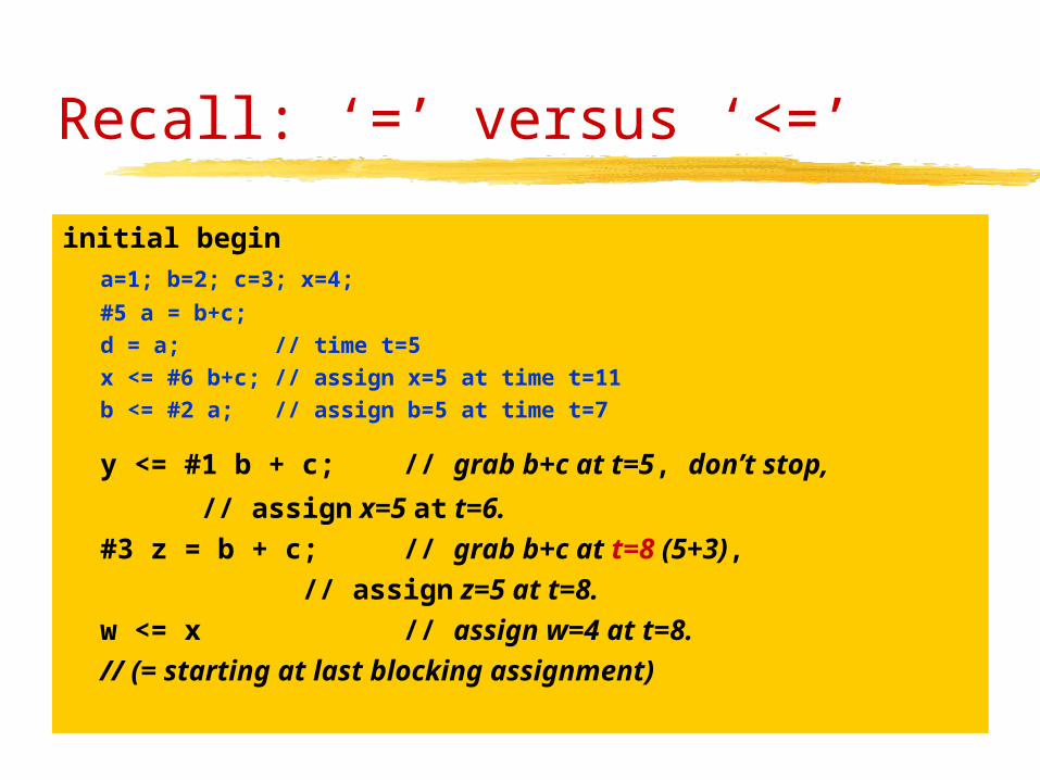
Recall: ‘=’ versus ‘<=’
initial begina=1; b=2; c=3; x=4;
#5 a = b+c;
d = a; // time t=5
x <= #6 b+c; // assign x=5 at time t=11
b <= #2 a; // assign b=5 at time t=7
y <= #1 b + c; // grab b+c at t=5, don’t stop,
// assign x=5 at t=6.
#3 z = b + c; // grab b+c at t=8 (5+3),
// assign z=5 at t=8.
w <= x // assign w=4 at t=8.
// (= starting at last blocking assignment)

Confused?
a = b + c // blocking assignment
a <= b + c // non-blocking assignment
#2 // delay by 2 time units
Block assignment with delay? Probably wrong!
Non-blocking assignment without delay? Bad idea!

Address Register
`define REG_DELAY 1
module add_reg(clk, reset, addr, reg_addr);
input clk, reset;
input [15:0] addr;
output [15:0] reg_addr;
reg [15:0] reg_addr;
always @(posedge clk)
if (reset)
reg_addr <= #(`REG_DELAY) 16 h’00;
else
reg_addr <= #(`REG_DELAY) address;
endmodule
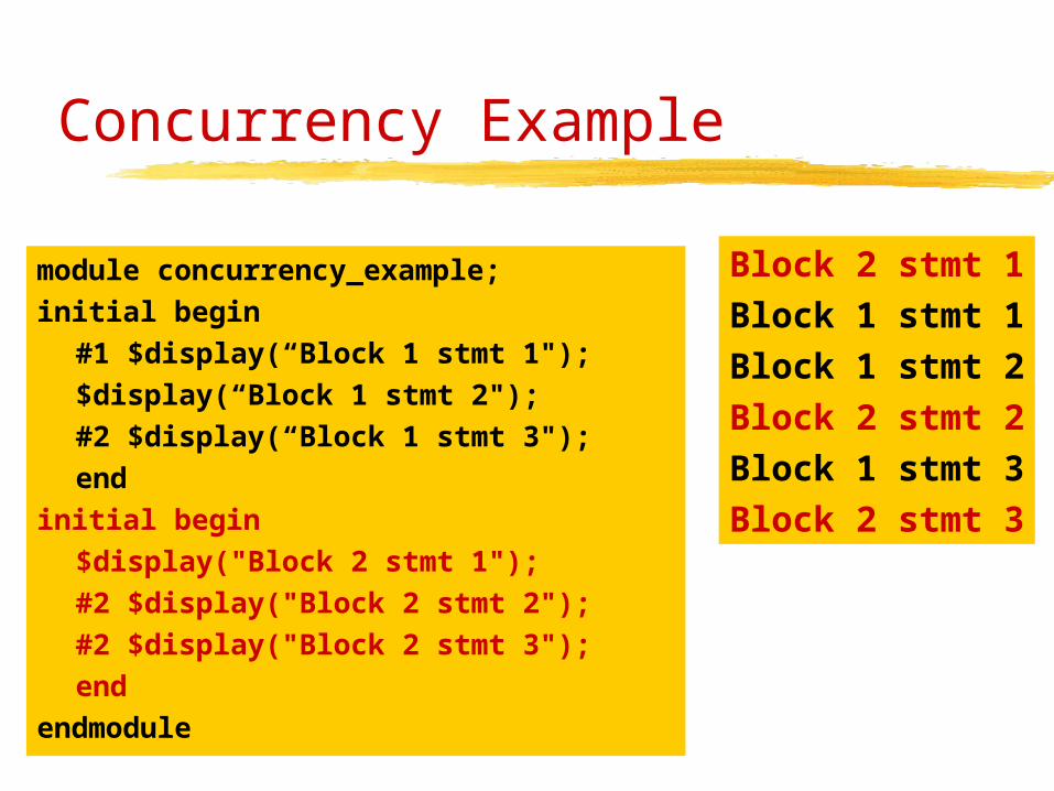
Concurrency Example
module concurrency_example;
initial begin
#1 $display(“Block 1 stmt 1");
$display(“Block 1 stmt 2");
#2 $display(“Block 1 stmt 3");
end
initial begin
$display("Block 2 stmt 1");
#2 $display("Block 2 stmt 2");
#2 $display("Block 2 stmt 3");
end
endmodule
Block 2 stmt 1
Block 1 stmt 1
Block 1 stmt 2
Block 2 stmt 2
Block 1 stmt 3
Block 2 stmt 3

Concurrency: fork and join
module concurrency_example;
initial fork
#1 $display(“Block 1 stmt 1");
$display(“Block 1 stmt 2");
#2 $display(“Block 1 stmt 3");
join
initial fork
$display("Block 2 stmt 1");
#2 $display("Block 2 stmt 2");
#2 $display("Block 2 stmt 3");
join
endmodule
Block 1 stmt 2
Block 2 stmt 1
Block 1 stmt 1
Block 1 stmt 3
Block 2 stmt 2
Block 2 stmt 3
Begin-End vs. Fork-Join
• In begin – end blocks, the statements are sequential and the delays are additive• In fork-join bocks, the statements are concurrent and the delays are independent
The two constructs can be used to compound statements. Nesting begin-end statements is not useful; neither is nesting for-join statements.
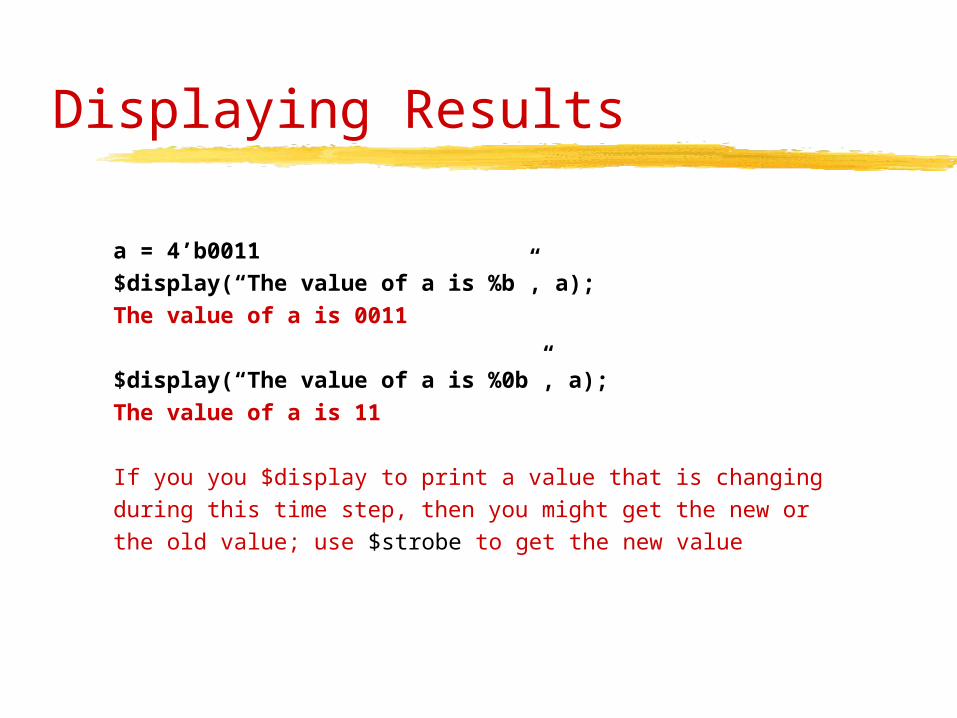
Displaying Results
a = 4’b0011
$display(“The value of a is %b”, a);
The value of a is 0011
$display(“The value of a is %0b”, a);
The value of a is 11
If you you $display to print a value that is changingduring this time step, then you might get the new orthe old value; use $strobe to get the new value

Displaying Results
• Standard displaying functions• $display, $write, $strobe, $monitor
• Writing to a file instead of stdout• $fdisplay, $fwrite, $fstrobe, $fmonitor
• Format specifiers• %b, %0b, %d, %0d, %h, %0h, %c, %s,…
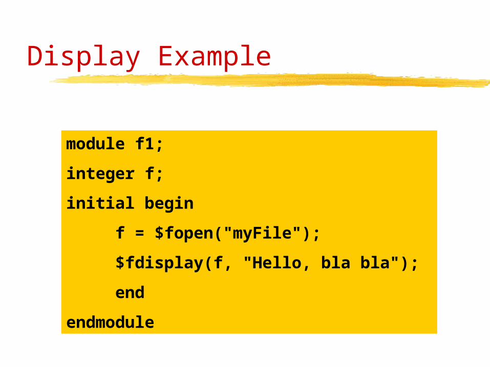
Display Example
module f1;
integer f;
initial begin
f = $fopen("myFile");
$fdisplay(f, "Hello, bla bla");
end
endmodule

Finite State Automata
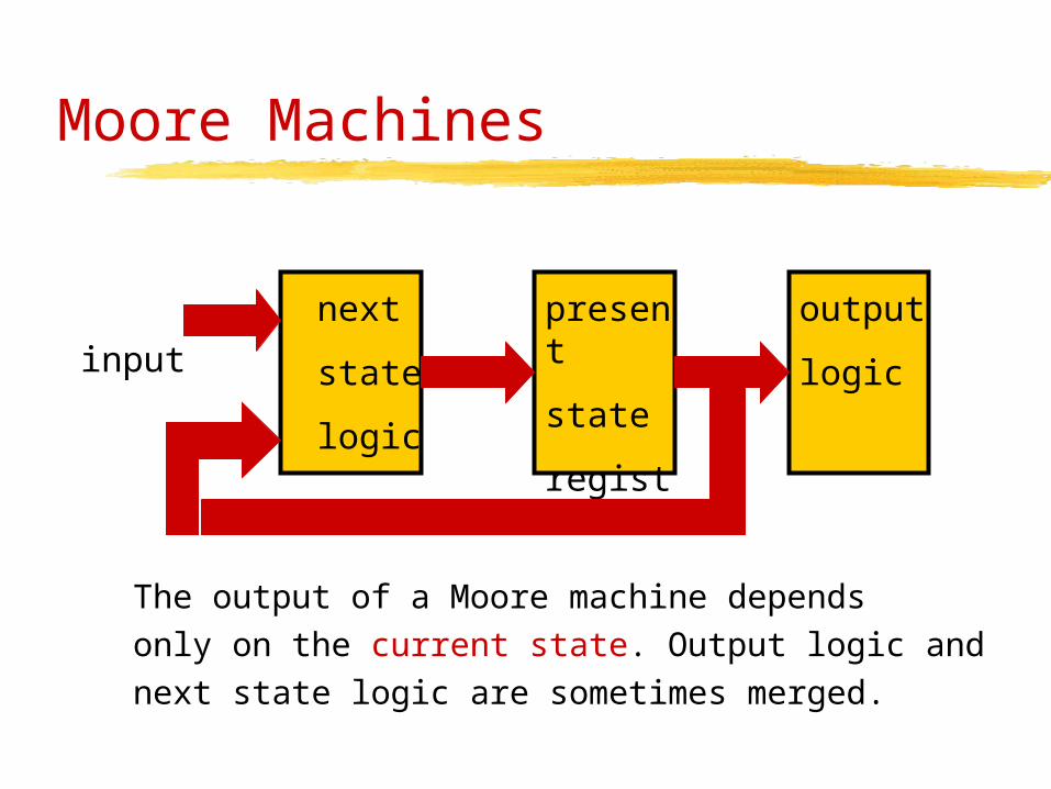
Moore Machines
The output of a Moore machine dependsonly on the current state. Output logic andnext state logic are sometimes merged.
next
state
logic
present
state
register
output
logic
input
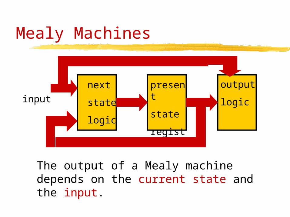
Mealy Machines
The output of a Mealy machine depends on the current state and the input.
next
state
logic
present
state
register
output
logic
input

State Machine Modeling
reg = state register, nsl = next state logic, ol = output logic
• Model reg separate, nsl separate, ol separate:• 3 always blocks of combinatorial logic; easy to maintain.
• Combine reg and nsl, keep ol separate• The state register and the output logic are strongly correlated;
it is usually more efficient to combine these two.
• Combine nsl and ol, keep register separate• Messy! Don’t do that!
• Combine everything into one always block• Can only be used for a Moore state machine. Why?
• Combine register and output logic into one always block• Can only be used for a Mealy state machine.

Example: Automatic Food Cooker

Moore Machine Example
Automatic food cooker• Has a supply of food• Can load food into the heater when
requested• Cooker unloads the food when cooking
done
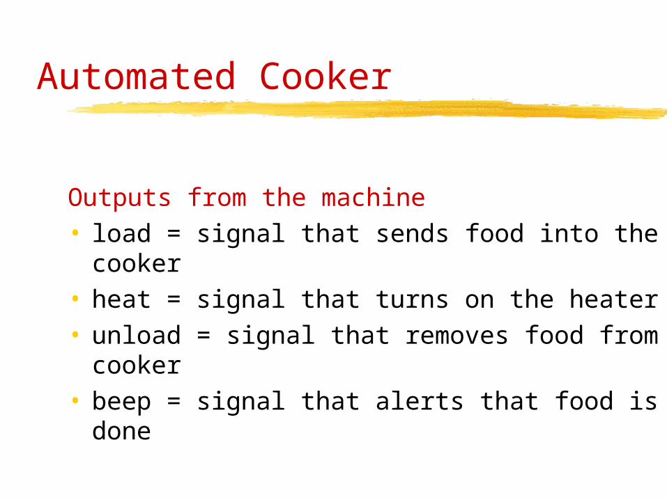
Automated Cooker
Outputs from the machine• load = signal that sends food into the
cooker• heat = signal that turns on the heater• unload = signal that removes food from
cooker• beep = signal that alerts that food is done
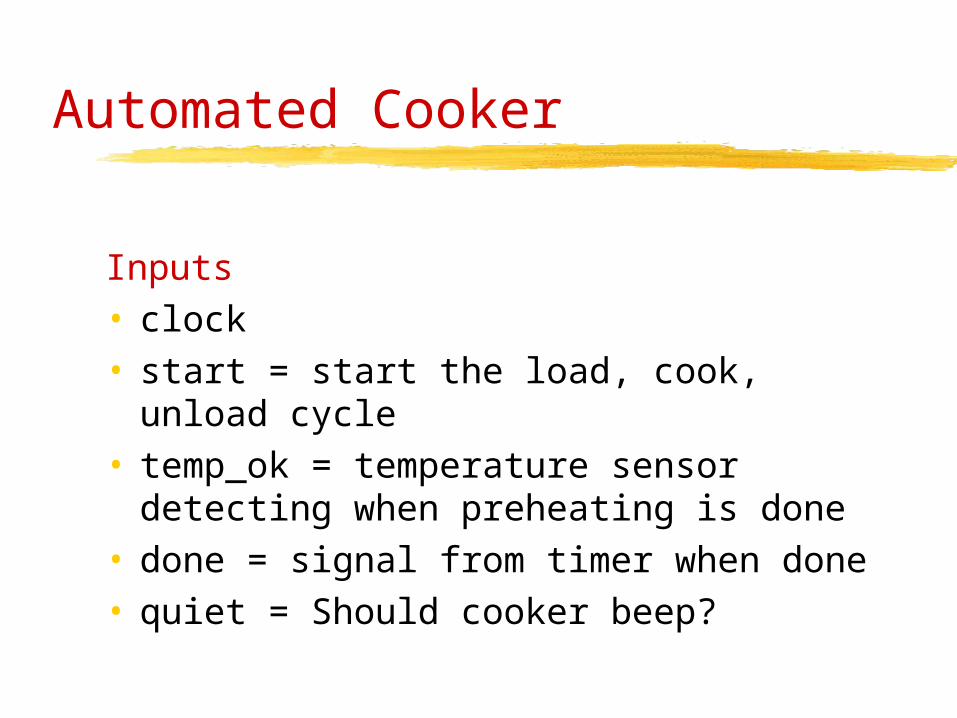
Automated Cooker
Inputs• clock • start = start the load, cook, unload
cycle• temp_ok = temperature sensor
detecting when preheating is done• done = signal from timer when done• quiet = Should cooker beep?
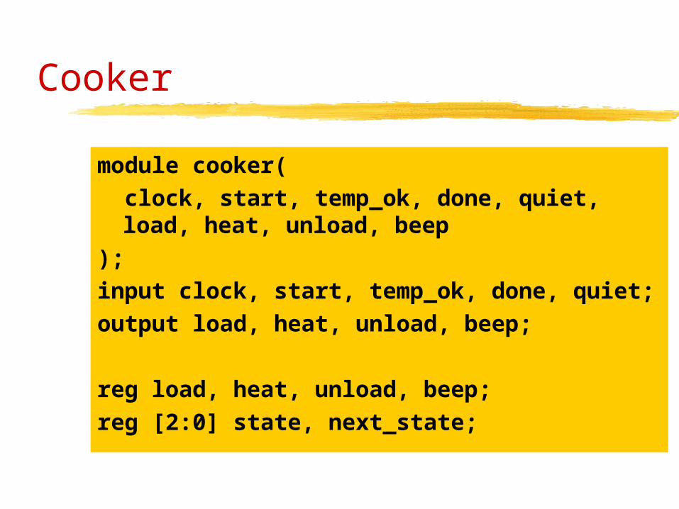
Cooker
module cooker(
clock, start, temp_ok, done, quiet, load, heat, unload, beep
);
input clock, start, temp_ok, done, quiet;
output load, heat, unload, beep;
reg load, heat, unload, beep;
reg [2:0] state, next_state;
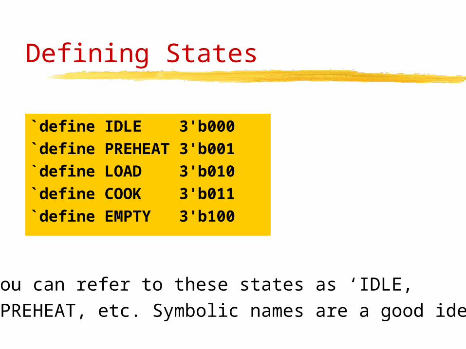
Defining States
`define IDLE 3'b000
`define PREHEAT 3'b001
`define LOAD 3'b010
`define COOK 3'b011
`define EMPTY 3'b100
You can refer to these states as ‘IDLE, ‘PREHEAT, etc. Symbolic names are a good idea!
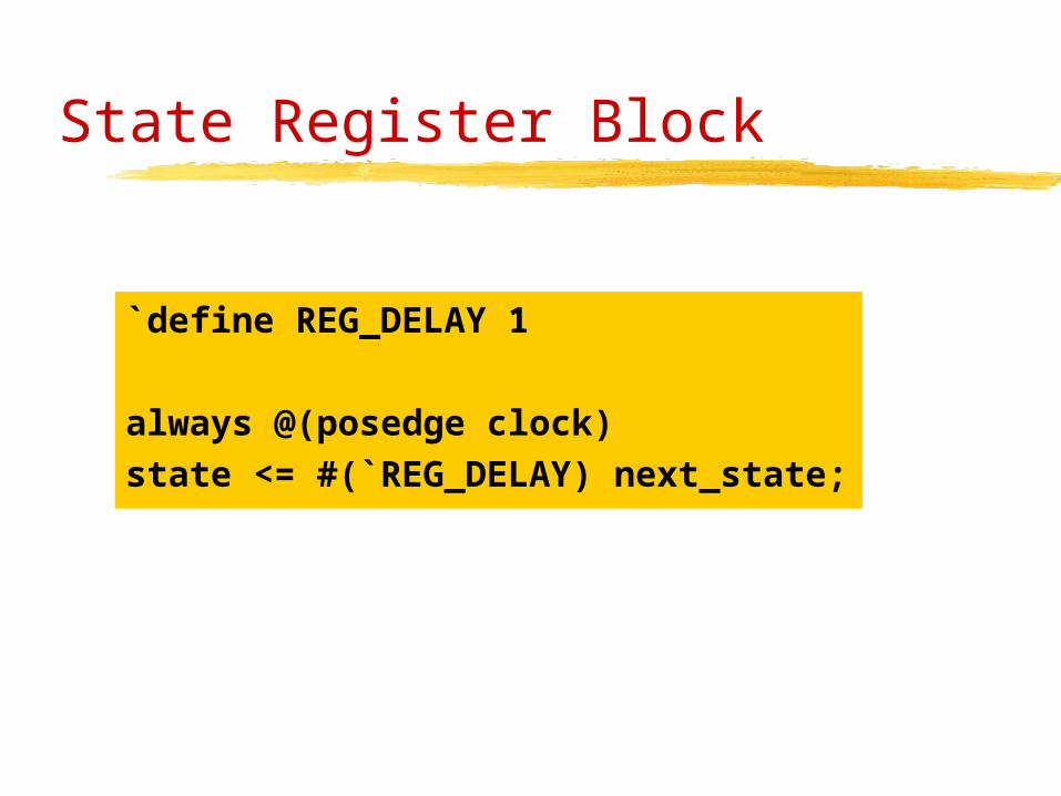
State Register Block
`define REG_DELAY 1
always @(posedge clock)
state <= #(`REG_DELAY) next_state;
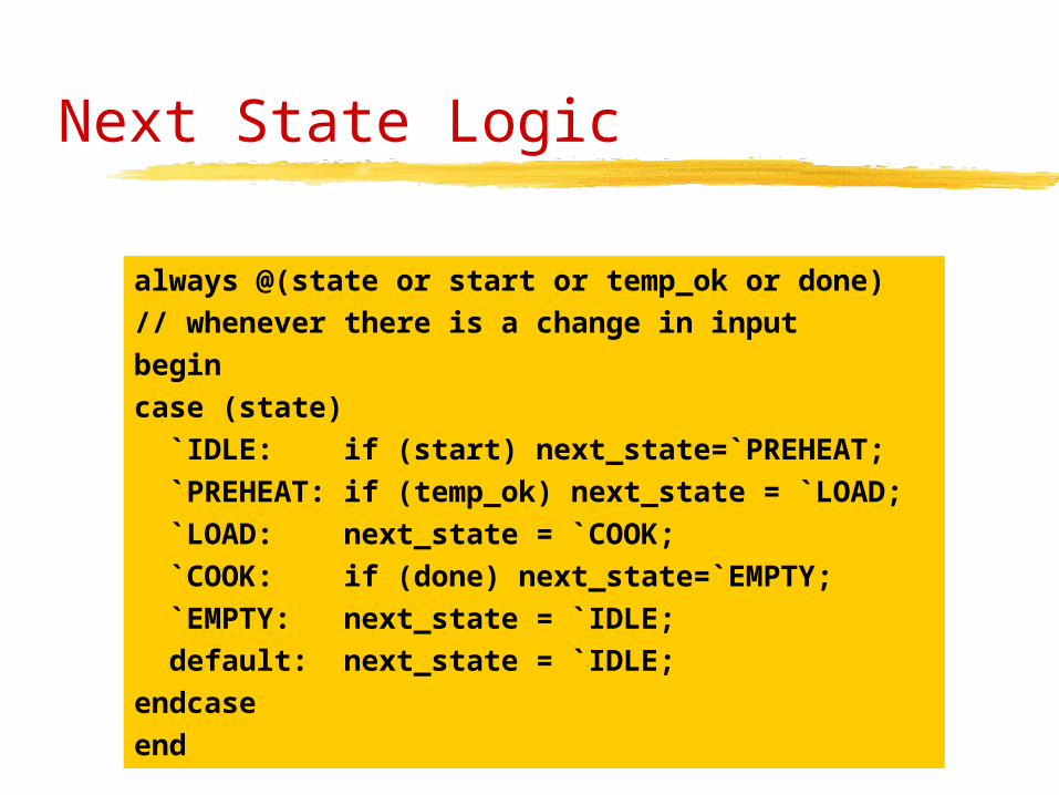
Next State Logic
always @(state or start or temp_ok or done)
// whenever there is a change in input
begin
case (state)
`IDLE: if (start) next_state=`PREHEAT;
`PREHEAT: if (temp_ok) next_state = `LOAD;
`LOAD: next_state = `COOK;
`COOK: if (done) next_state=`EMPTY;
`EMPTY: next_state = `IDLE;
default: next_state = `IDLE;
endcase
end
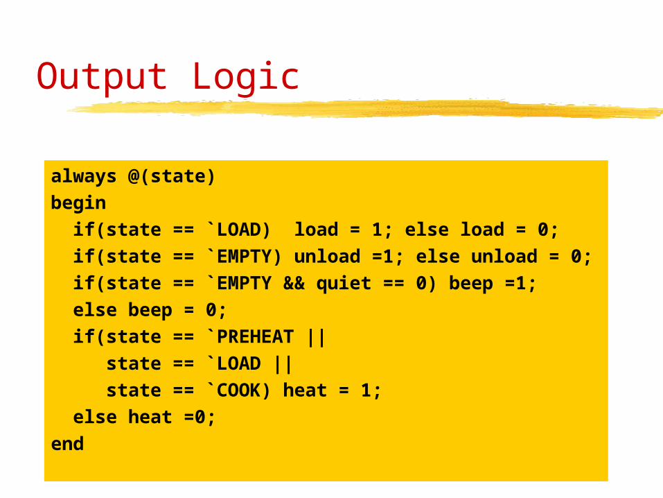
Output Logic
always @(state)
begin
if(state == `LOAD) load = 1; else load = 0;
if(state == `EMPTY) unload =1; else unload = 0;
if(state == `EMPTY && quiet == 0) beep =1;
else beep = 0;
if(state == `PREHEAT ||
state == `LOAD ||
state == `COOK) heat = 1;
else heat =0;
end

`define IDLE 3'b000
`define PREHEAT 3'b001
`define LOAD 3'b010
`define COOK 3'b011
`define EMPTY 3'b100
module cooker(clock,...);always @(state or start or temp_ok or done)
begin
case (state)
`IDLE: if (start) next_state=`PREHEAT;
`PREHEAT: if (temp_ok) next_state = `LOAD;
`LOAD: next_state = `COOK;
`COOK: if (done) next_state=`EMPTY;
`EMPTY: next_state = `IDLE;
default: next_state = `IDLE;
endcase
end`define REG_DELAY 1
always @(posedge clock)
state <= #(`REG_DELAY) next_state;
always @(state)
begin
if(state == `LOAD) load = 1; else load = 0;
if(state == `EMPTY) unload =1; else unload = 0;
if(state == `EMPTY && quiet == 0) beep =1;
else beep = 0;
if(state == `PREHEAT ||
state == `LOAD ||
state == `COOK) heat = 1;
else heat =0;
end

Pipelined Processor

Basic Idea
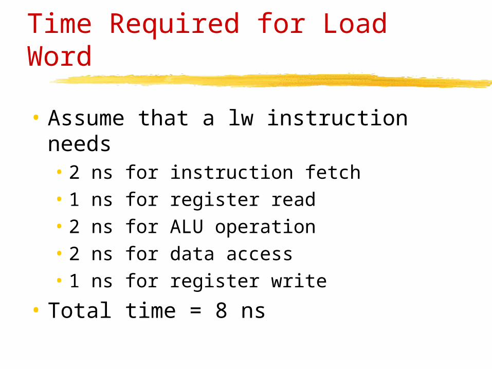
Time Required for Load Word
• Assume that a lw instruction needs• 2 ns for instruction fetch• 1 ns for register read• 2 ns for ALU operation• 2 ns for data access• 1 ns for register write
• Total time = 8 ns

Non-Pipelined vs. Pipelined Execution
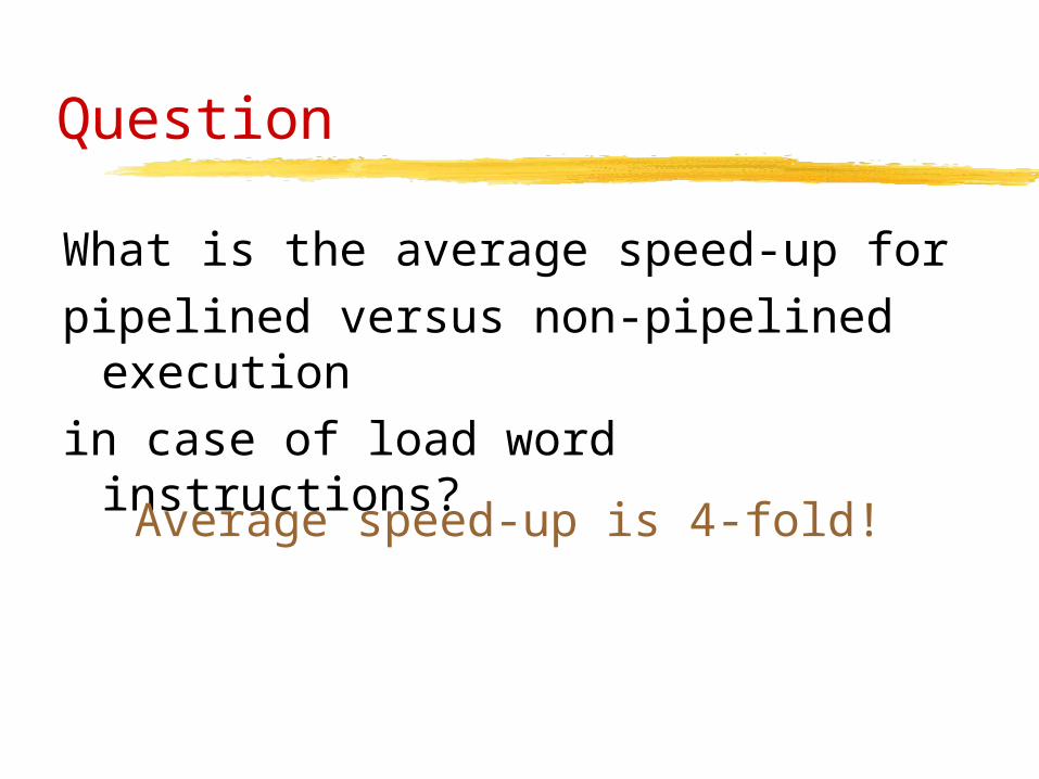
Question
What is the average speed-up forpipelined versus non-pipelined
executionin case of load word instructions?
Average speed-up is 4-fold!
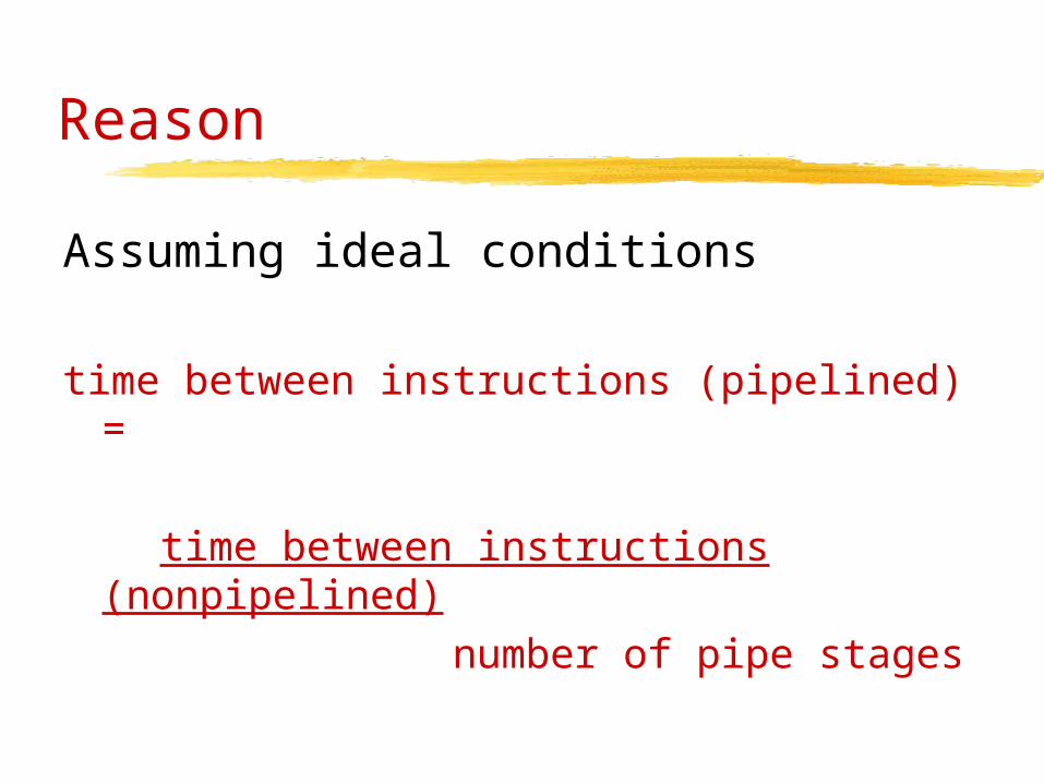
Reason
Assuming ideal conditions
time between instructions (pipelined) =
time between instructions (nonpipelined) number of pipe stages
MIPS Appreciation Day
• All MIPS instructions have the same length• => simplifies the pipeline design• fetch in first stage and decode in second stage
• Compare with 80x86• Instructions 1 byte to 17 bytes• Pipelining is much more challenging
Obstacles to Pipelining
• Structural Hazards• hardware cannot support the combination of
instructions in the same clock cycle
• Control Hazards• need to make decision based on results of one
instruction while other is still executing
• Data Hazards• instruction depends on results of instruction
still in pipeline

Structural Hazards
• Laundry examples• if you have a washer-dryer combination
instead of a separate washer and dryer,…• separate washer and dryer, but roommate
is busy doing something else and does not put clothes away [sic!]
• Computer architecture• competition in accessing hardware
resources, e.g., access memory at the same time

Control Hazards
Control hazards arise from the need tomake a decision based on results of aninstruction in the pipeline• Branches: What is the next instruction?• How can we resolve the problem?
• Stall the pipeline until computations done• or predict the result • delayed decision

Stall on Branch
• Assume that all branch computations are done in stage 2
• Delay by one cycle to wait for the result

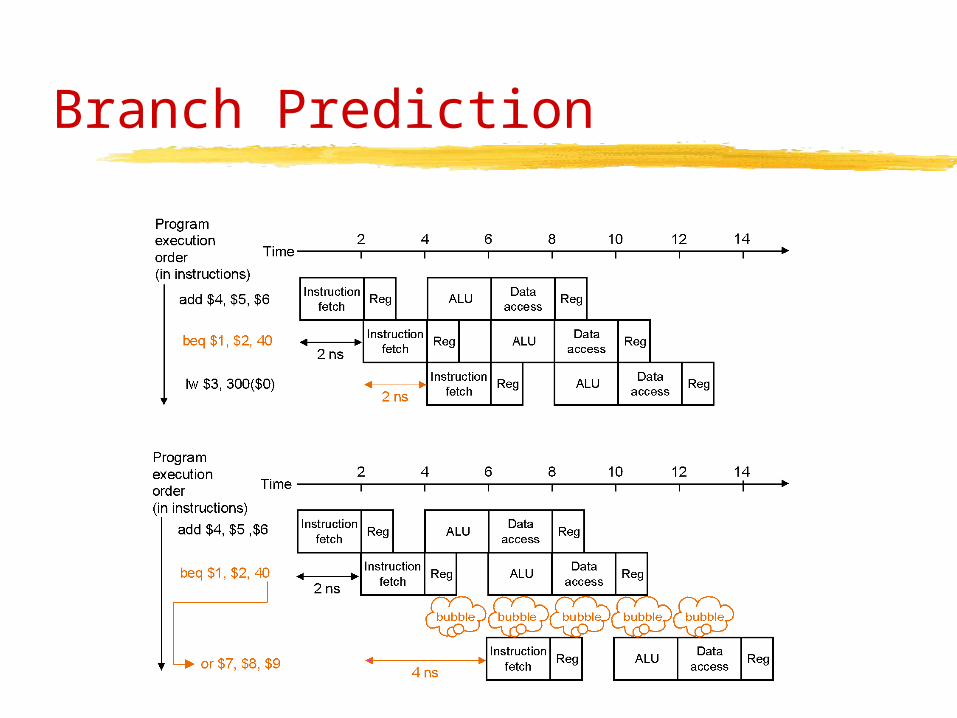
Branch Prediction
• Predict branch result• For example, predict always that branch is not taken (e.g. reasonable for while instructions)• if choice is correct, then pipeline runs at
full speed• if choice is incorrect, then pipeline stalls
Branch Prediction
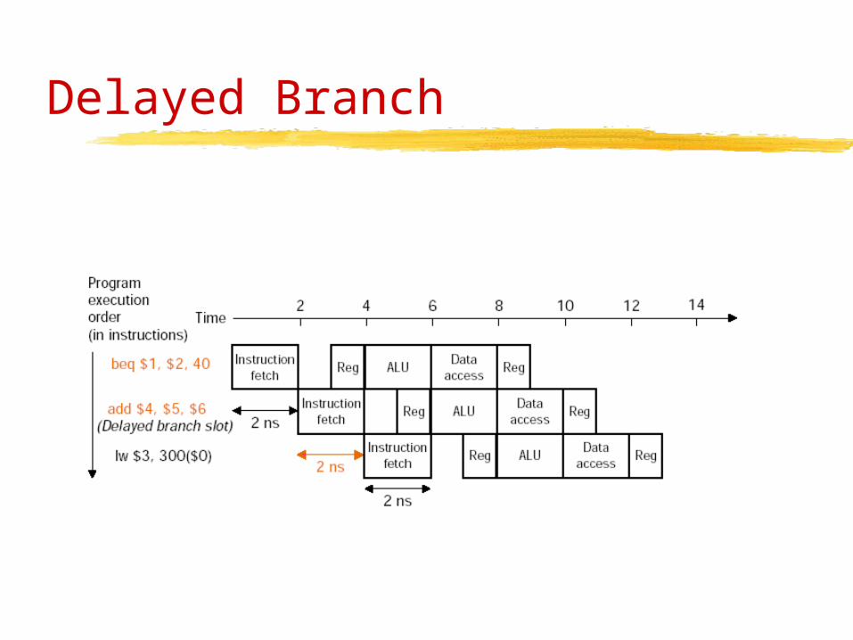
Delayed Branch

Data Hazards
• A data hazard results if an instruction depends on the result of a previous instruction• add $s0, $t0, $t1• sub $t2, $s0, $t3 // $s0 to be determined
• These dependencies happen often, so it is not possible to avoid them completely
• Use forwarding to get missing data from internal resources once available

Forwarding
add $s0, $t0, $t1
sub $t2, $s0, $t3

Single Cycle Datapath
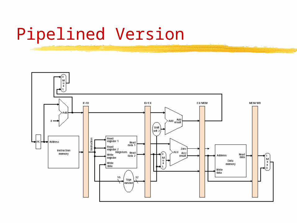
Pipelined Version