vc-a61p rs-232 command set - lumens
TRANSCRIPT
RS127 - VC-A61P RS-232 command set
VC-A61P RS-232 command set
No Issue Date Description Apply Firmware
1 2019/09/24 First version. NA
*Notice:
1. The RS-232 command list is for VC-A61P
2. The yellow highlight means the latest update. 3. The blue highlight means the deleted item.

RS127 - VC-A61P RS-232 command set
1 ACK & Completion message
Reply Packet Note
Ack X0 4Y FF Y = socket number
Completion (commands) X0 5Y FF Y = socket number
Completion (Inquiries) X0 50 ... FF
X = 9 to F==>camera address + 8 , Y=1 to 2
1. Communication Protocol
Transmit Method: Asynchronous Interface Half
Duplex Serial Communication
Transmit Speed: 9600bps or 38400bps
Start bit: 1Bit
Parity Check: NA
Data Bit: 8Bit
Stop Bit: 1Bit
2. The wire diagram
The RS232 wire diagram between presenter and
remote controller as below

RS127 - VC-A61P RS-232 command set
2 Error message Error Packet Description
X0 60 02 FF Syntax Error
X0 60 03 FF Command buffer full
X0 6Y 04 FF Command cancelled
X0 6Y 05 FF No socket (to be cancelled)
X0 6Y 41 FF Command not executable
X = 9 to F==>camera address + 8, Y = socket number, Y=0 to 2, 0: Inqurity not execution
3 Command execution cancel
Cancel Packet Note
Cancel 8X 2Y FF Y = socket number
X = 1 to 7==>camera address, Y = socket number, Y=1 to 2
4 Network Change
Packet Note
Address 88 30 01 FF Always broadcasted(Reply:88
30 0w FF w:1+Address)
Network Change X0 38 FF
X = 9 to F==>camera address + 8
5 IF_Clear
Command Reply Packet Note
IF_Clear 8X 01 00 01 FF X0 50 FF
IF_Clear (broadcast) 88 01 00 01 FF 88 01 00 01 FF
X = 1 to 7==>camera address (For inquiry packet)
X = 9 to F==>camera address +8 (For reply packet)

RS127 - VC-A61P RS-232 command set
6 Zoom Focus Position Table
Zoom Position Wide end Tele end
0000 to 4000
Focus Position Far end Near end
000 to 47A
7 AE_Iris Table
Iris
Index(pq) Value
0F Close
0E F1.6
0D F2
0C F2.2
0B F2.7
0A F3.2
09 F3.8
08 F4.5
07 F5.4
06 F6.3
05 F7.8
04 F9
03 F11
02 F13
01 F16
00 F18

RS127 - VC-A61P RS-232 command set
8 AE_Shutter Table
Shutter Speed
Index(pq) 60/30 mode 50/25 mode
00 1/10000 1/10000
01 1/5000 1/5000
02 1/3000 1/3000
03 1/2500 1/2500
04 1/2000 1/1750
05 1/1500 1/1250
06 1/1000 1/1000
07 1/725 1/600
08 1/500 1/425
09 1/350 1/300
0A 1/250 1/215
0B 1/180 1/150
0C 1/120 1/120
0D 1/100 1/100
0E 1/90 1/75
0F 1/60 1/50
10 1/30 1/25
11 1/15 1/12
12 1/8 1/6
13 1/4 1/3
14 1/2 1/2
15 1/1 1/1

RS127 - VC-A61P RS-232 command set
9 AE_Gain Table
Gain
Index(pq) Value
0F +45 dB
0E +42 dB
0D +39 dB
0C +36 dB
0B +33 dB
0A +30 dB
09 +27 dB
08 +24 dB
07 +21 dB
06 +18 dB
05 +15 dB
04 +12 dB
03 +9 dB
02 +6 dB
01 +3 dB
00 0 dB

RS127 - VC-A61P RS-232 command set
10 AE_Exposure Comp. Table
Exposure Comp.
Index(p) Value(Level) (Gain)Value
0A 5 +5 dB
09 4 +4 dB
08 3 +3 dB
07 2 +2 dB
06 1 +1 dB
05 0 0 dB
04 -1 -1 dB
03 -2 -2 dB
02 -3 -3 dB
01 -4 -4 dB
00 -5 -5 dB
0A 5 +5 dB
09 4 +4 dB
08 3 +3 dB
07 2 +2 dB

RS127 – VC-A61P RS-232 command set
11 Camera RS232 Command List Command Set Command Command Packet Comments
AddressSet Broadcast 88 30 01 FF Address setting
IF_Clear Broadcast 88 01 00 01 FF I/F Clear
CommandCancel – 8x 2p FF p: Socket No. (=1 or 2)
CAM_Power On 8x 01 04 00 02 FF Power ON/OFF
Off (Standby) 8x 01 04 00 03 FF
CAM_Zoom Stop 8x 01 04 07 00 FF
Tele (Standard) 8x 01 04 07 02 FF
Wide (Standard) 8x 01 04 07 03 FF
Tele Step 8x 01 04 07 04 FF
Wide Step 8x 01 04 07 05 FF
Tele (Variable) 8x 01 04 07 2p FF p=0 (Low) to 7 (High)
Wide (Variable) 8x 01 04 07 3p FF
Direct 8x 01 04 47 0p 0q 0r 0s FF pqrs: Zoom Position(0x0000~0x4000) , Optical Zoom
Tele max position: 0x4000
Direct(Speed Variable) 8x 01 04 47 0p 0q 0r 0s 0t FF pqrs: Zoom Position(0x0000~0x4000) , Optical Zoom
Tele max position: 0x4000, t:0~7(0 :Low, 7:High)
Zoom Memory Mode 8x 01 04 47 00 02 FF Zoom Memory Mode ON/OFF
8x 01 04 47 00 03 FF
CAM_Focus Stop 8x 01 04 08 00 FF Enabled during Manual Focus Mode
Far (Standard) 8x 01 04 08 02 FF
Near (Standard) 8x 01 04 08 03 FF
Far Step 8x 01 04 08 04 FF
Near Step 8x 01 04 08 05 FF
Far (Variable) 8x 01 04 08 2p FF p=0 (Low) to 7 (High)

RS127 – VC-A61P RS-232 command set
Command Set Command Command Packet Comments
Near (Variable) 8x 01 04 08 3p FF (* Enabled during Manual Focus Mode)
Direct 8x 01 04 48 0p 0q 0r 0s FF pqrs: Focus Position , pqrs parameters are in the
General Zoom Foucs Table 0x00 ~ 0x47A
(* Enabled during Manual Focus Mode)
Auto Focus 8x 01 04 38 02 FF AF ON/OFF
Manual Focus 8x 01 04 38 03 FF
Auto/Manual 8x 01 04 38 10 FF
One Push Trigger 8x 01 04 18 01 FF One Push AF Trigger(* Enabled during Manual Focus
Mode)
CAM_Curve Curve tracking 8x 01 04 38 03 02 FF Curve tracking ON/OFF
Zoom tracking 8x 01 04 38 03 03 FF
AF Sensitivity High 8x 01 04 58 01 FF High / Middle / Low
Middle 8x 01 04 58 02 FF
Low 8x 01 04 58 03 FF
AF Frame Auto 8x 01 04 5C 01 FF Auto / Full Frame / Center
Full Frame 8x 01 04 5C 02 FF
Center 8x 01 04 5C 03 FF
Auto/Full Frame/Center 8x 01 04 5C 10 FF
CAM_ZoomFocus Direct 8x 01 04 47 0p 0q 0r 0s 0t 0u 0v
0w FF
pqrs: Zoom Position(0x0000~0x4000) tuvw: Focus
Position(0x00 ~ 0x47A)
(* Enabled during Manual Focus Mode)
CAM_Initialize Lens 8x 01 04 19 01 FF Lens Initialization Start

RS127 – VC-A61P RS-232 command set
Command Set Command Command Packet Comments
Resolution Settting Select Resolution 8x 01 06 35 0p 0q FF pq:
0x05:QFHD 4K(3840 x 2160) - 29.97p
0x06:QFHD 4K(3840 x 2160) - 25p
0x08:FHD 1080P(1920 x 1080) - 59.94p
0x09:FHD 1080P(1920 x 1080) - 50p
0x0B:FHD 1080P(1920 x 1080) - 29.97p
0x0C:FHD 1080P(1920 x 1080) - 25p
0x0E:HD 720P(1280 x 720) - 59.94p
0x0F:HD 720P(1280 x 720) - 50p
0x11:HD 720P(1280 x 720) - 29.97p
0x12:HD 720P(1280 x 720) - 25p
HDMI Output Range 16~235 8x 01 06 37 01 FF HDMI Output Range : 16~235 / 1~254
1~254 8x 01 06 37 02 FF
CAM_WB Auto 8x 01 04 35 00 FF Auto
Indoor mode Indoor 8x 01 04 35 01 FF
CAM_WB_RGAIN
Outdoor 8x 01 04 35 02 FF Outdoor mode
One Push WB 8x 01 04 35 03 FF One Push WB mode
ATW 8x 01 04 35 04 FF Auto Tracing White Balance
Manual 8x 01 04 35 05 FF Manual mode
Sodium Lamp 8x 01 04 35 0C FF Sodium lamp source fixed mode
One Push Trigger 8x 01 04 10 05 FF One Push WB Trigger(* Enabled during One Push WB
Mode)
Reset 8x 01 04 03 00 FF Manual R gain Setting
(* Enabled during WB Manual mode )
pq = 0x00 To 0x80

RS127 – VC-A61P RS-232 command set
Command Set Command Command Packet Comments
Up 8x 01 04 03 02 FF One Push WB Trigger(* Enabled during One Push WB
Mode)
CAM_WB_BGAIN
Down 8x 01 04 03 03 FF
Manual B gain Setting
(* Enabled during WB Manual mode )
pq = 0x00 To 0x80
Direct 8x 01 04 43 00 00 0p 0q FF
Reset 8x 01 04 04 00 FF
Up 8x 01 04 04 02 FF
CAM_AE
Down 8x 01 04 04 03 FF
Automatic Exposure mode
Manual Control mode
Direct 8x 01 04 44 00 00 0p 0q FF
Full Auto 8x 01 04 39 00 FF
Manual 8x 01 04 39 03 FF
CAM_Flickerless
Shutter Priority 8x 01 04 39 0A FF Shutter Priority Automatic Exposure mode
Iris Priority 8x 01 04 39 0B FF Iris Priority Automatic Exposure mode
Off 8x 01 04 3C 00 FF
50Hz 8x 01 04 3C 01 FF
60Hz 8x 01 04 3C 02 FF
CAM_Shutter Reset 8x 01 04 0A 00 FF Shutter Setting
(* Enabled during AE Shutter Priority/Manual Mode)
Up 8x 01 04 0A 02 FF
Down 8x 01 04 0A 03 FF
CAM_Iris
Direct 8x 01 04 4A 00 00 0p 0q FF pq: Shutter Position , pq: 00 To 15
(1/1 ~ 1/10000)
Iris Setting
(* Enabled during Iris Priority/Manual Mode)
Reset 8x 01 04 0B 00 FF
Up 8x 01 04 0B 02 FF
Down 8x 01 04 0B 03 FF pq: Shutter Position , pq: 00 To 15
(1/1 ~ 1/10000)

RS127 – VC-A61P RS-232 command set
Command Set Command Command Packet Comments
Direct 8x 01 04 4B 00 00 0p 0q FF pq: Iris Position , pq: 00 To 0F
p: Iris F number , p: 3 To A (* Disabled during AE
Manual Mode and IrisPri Mode)
Iris Limit (Min.) 8x 01 04 2B 0p FF
CAM_Gain
Iris Limit (Max.) 8x 01 04 2A 0p FF p: Iris F number , p: 3 To A (* Disabled during AE
Manual Mode and IrisPri Mode)
Illegal Open Iris ON/OFF
Illegal Iris Open 8x 01 04 2F 02 FF
Down 8x 01 04 2F 03 FF
Reset 8x 01 04 0C 00 FF Gain Setting
(* Enabled during AE Manual Mode)
Up 8x 01 04 0C 02 FF p: Iris F number , p: 3 To A (* Disabled during AE
Manual Mode and IrisPri Mode)
Down 8x 01 04 0C 03 FF p: Iris F number , p: 3 To A (* Disabled during AE
Manual Mode and IrisPri Mode)
Direct
Gain Limit
8x 01 04 4C 00 00 0p 0q FF pq: Gain Position, pq:00 To 0F (* Enabled during AE
Manual Mode)
(* 0dB ~ +45dB)
p: Gain Position , p: 3 To F (* Disabled during AE
Manual Mode)
8x 01 04 2C 0p FF
CAM_Bright
CAM_ExpComp
Reset 8x 01 04 0D 00 FF Bright Setting
Up 8x 01 04 0D 02 FF
Down 8x 01 04 0D 03 FF
Direct 8x 01 04 4D 00 00 0p 0q FF pq: Bright Position, pq:0x00~0x0F
(* Enabled during Image Mode = Custom mode )
On 8x 01 04 3E 02 FF Exposure Compensation ON/OFF
Off 8x 01 04 3E 03 FF
Exposure Compensation Amount Setting Reset 8x 01 04 0E 00 FF

RS127 – VC-A61P RS-232 command set
Command Set Command Command Packet Comments
Up 8x 01 04 0E 02 FF (* Enabled during ExpComp On )
Down 8x 01 04 0E 03 FF
CAM_BackLight
CAM_SpotAE
Direct 8x 01 04 4E 00 00 0p 0q FF pq: ExpComp Position , pq: 00 To 0A (* Enabled
during ExpComp On )
Back Light Compensation ON/OFF
(* Enabled during AE Full Auto Mode)
On 8x 01 04 33 02 FF
Off 8x 01 04 33 03 FF
On 8x 01 04 59 02 FF Spot Mode ON/OFF
Off 8x 01 04 59 03 FF
Position 8x 01 04 29 0p 0q 0r 0s FF pq: X - axis, pq: 00 To 06 (* Center position : 3)
rs : Y - axis, rs : 00 To 04 (* Center position : 2)
CAM_Aperture
(Sharpness)
Reset 8x 01 04 02 00 FF Aperture Control
Up 8x 01 04 02 02 FF
CAM_2DNR
Down 8x 01 04 02 03 FF
pq: Aperture Gain, pq: 00 To 0E Direct 8x 01 04 42 00 00 0p 0q FF
Set 2DNR Level 8x 01 04 53 0p FF p: NR Level Setting, p: 0 To 3
CAM_3DNR
CAM_Gamma
CAM_LR_Reverse
Set 3DNR Level 8x 01 04 54 0p FF p: NR Level Setting,
p: 0: OFF
1: Low
2: Type
3: Max
Gamma setting 8x 01 04 5B 0p FF
On 8x 01 04 61 02 FF

RS127 – VC-A61P RS-232 command set
Command Set Command Command Packet Comments
p: 0 To 3
(* Enabled during Image Mode = Custom mode )
Mirror Image ON/OFF
Off 8x 01 04 61 03 FF pq: Aperture Gain, pq: 00 To 0E
CAM_PictureEffect Off 8x 01 04 63 00 FF Picture Effect Setting
Neg.Art 8x 01 04 63 02 FF
B&W 8x 01 04 63 04 FF
CAM_PictureFlip On 8x 01 04 66 02 FF Picture flip ON/OFF
Off 8x 01 04 66 03 FF
CAM_Rotation
(Mirror + Flip)
CAM_ICR
On 8x 01 04 67 02 FF Rotation 180 degree ON/OFF
ICR ON/OFF Off 8x 01 04 67 03 FF
On 8x 01 04 01 02 FF
CAM_AutoICR
Off 8x 01 04 01 03 FF
Auto ICR ON/OFF On 8x 01 04 51 02 FF
Off 8x 01 04 51 03 FF
pq: Threshold Level, pq: 00 To FF Threshold 8x 01 04 21 00 00 0p 0q FF
CAM_Memory
(Preset)
Reset 8x 01 04 3F 00 pp FF pp: Memory Number (pp: 0x00 To 0x7F)
(* Preset address : 0~127) Set 8x 01 04 3F 01 pp FF
Recall 8x 01 04 3F 02 pp FF
pp: Memory Number (pp: 0x00 To 0x7F)
(* Preset address : 128~255)
Reset 8x 01 04 3F 10 pp FF

RS127 – VC-A61P RS-232 command set
Command Set Command Command Packet Comments
Set 8x 01 04 3F 11 pp FF pq: Threshold Level, pq: 00 To FF
CAM_Mute
CAM_ColorGain(Saturati
on)
IR_Receive
Recall 8x 01 04 3F 12 pp FF
Mute ON
Mute OFF
On 8x 01 04 75 02 FF
Off 8x 01 04 75 03 FF
On/Off 8x 01 04 75 10 FF Mute Trigger
pq: color Gain, pq:0x00~0x0F
(* Enabled during Image Mode = Custom mode )
IR(remote commander) receive ON/OFF
Direct 8x 01 04 49 00 00 0p 0q FF
On 8x 01 06 08 02 FF
Off 8x 01 06 08 03 FF
On/Off 8x 01 06 08 10 FF
Pan-tiltDrive Up 8x 01 06 01 VV WW 03 01 FF VV: Pan speed 0x01 (low speed) to 0x18 (high speed)
WW: Tilt Speed 0x01 (low speed) to 0x18 (high speed)
Down 8x 01 06 01 VV WW 03 02 FF
Left 8x 01 06 01 VV WW 01 03 FF
Right 8x 01 06 01 VV WW 02 03 FF
UpLeft 8x 01 06 01 VV WW 01 01 FF
UpRight 8x 01 06 01 VV WW 02 01 FF
Pan-tiltLimitSet
DownLeft 8x 01 06 01 VV WW 01 02 FF
DownRight 8x 01 06 01 VV WW 02 02 FF
Stop 8x 01 06 01 VV WW 03 03 FF
AbsolutePosition 8x 01 06 02 VV WW 0Y 0Y 0Y 0Y
0Z 0Z 0Z 0Z FF
YYYY : Pan Position 0x0000 to 0x6A40 & 0x95C0 to
0xFFFF (center 0000)
ZZZZ : Tilt Position 0x0000 to 0x3840 & 0xED40 to

RS127 – VC-A61P RS-232 command set
Command Set Command Command Packet Comments
0xFFFF (center 0000)
RelativePosition 8x 01 06 03 VV WW 0Y 0Y 0Y 0Y
0Z 0Z 0Z 0Z FF menu up
Home 8x 01 06 04 FF
Reset 8x 01 06 05 FF
LimitSet 8x 01 06 07 00 0W 0Y 0Y 0Y 0Y
0Z 0Z 0Z 0Z FF
W: 1 UpRight YYYY: Pan Limit Position
0x0000~0x6A40 ZZZZ: Tilt Limit Position
0x0000~0x3840
W: 0 DownLeft YYYY: Pan Limit Position
0xFFFF~0x95C0 ZZZZ: Tilt Limit Position
0xFFFF~0xED40
LimitClear 8x 01 06 07 01 0W 07 0F 0F 0F
07 0F 0F 0F FF
W: 1:Right,UP clear, 0:Left, Down clear
Factory Reset
CAM_Image_Mode
System Factroy Reset 8x 01 04 3F 03 00 FF Factory Reset
Image Mode Default/Custom Default 8x 01 04 3F 04 00 FF
CAM_Image_Load
CAM Prompt
Custom 8x 01 04 3F 04 01 FF
p : Load Image mode - default to Custom (p=0)
OSD Prompt ON/OFF
Image Mode Load 8x 01 04 3F 05 0p FF
On 8x 01 04 07 00 02 FF
CAM Model ID
Off 8x 01 04 07 00 03 FF
ppqq: Vender ID (0001: Sony) , rrss:Model ID(0513:
SRG-300H)
Set Camera model ID 8x 01 04 23 pp qq rr ss FF
CAM_ColorHue
SYS_Menu
Direct 8x 01 04 4F 00 00 0p 0q FF pq: color Hue, pq:0x00~0x0F
(* Enabled during Image Mode = Custom mode ) On 8x 01 06 06 02 FF

RS127 – VC-A61P RS-232 command set
Command Set Command Command Packet Comments
turn on the menu screen
Off 8x 01 06 06 03 FF turn off the menu screen
On/Off 8x 01 06 06 10 FF turn on/off the menu screen
Enter 8x 01 7E 01 02 00 01 FF menu enter
Up 8x 01 06 01 01 01 03 01 FF menu up
Down 8x 01 06 01 01 01 03 02 FF menu down
menu left Left 8x 01 06 01 01 01 01 03 FF
Tally Mode
Right 8x 01 06 01 01 01 02 03 FF menu right
p: 0: (Red:OFF / Green:OFF)
4: (Red:Low light / Green:OFF) - Tally Lamp must
be Enabled
5: (Red:Highlight / Green:OFF) - Tally Lamp must
be Enabled
6: (Red:OFF / Green:Highlight) - Tally Lamp must
be Enabled (VC-A61P/VC-A71P)
7: (Red:Highlight / Green:Highlight) - Tally Lamp
must be Enabled (VC-A61P/VC-A71P)
Set Tally Mode 8x 01 7E 01 0A 01 0p FF
Tally_Lamp On 8x 01 7E 01 0A 00 02 FF Tally Lamp ON/OFF
Off 8x 01 7E 01 0A 00 03 FF
OSD_Cross_line On 8x 01 04 75 DD 04 02 FF OSD Cross Line ON/OFF
Off 8x 01 04 75 DD 04 03 FF
IP_DHCP_OnOff On 8x 01 7C 01 02 FF Set DHCP ON/OFF

RS127 – VC-A61P RS-232 command set
Command Set Command Command Packet Comments
Off 8x 01 7C 01 03 FF
IP_Address_IPv4
Set IP Addresss 8x 01 7C 02 0p 0q 0r 0s 0t 0u 0v
0x FF
address : pq.rs.tu.vx (HEX), pq = 0~255, rs = 0~255,
tu = 0~255, vx = 0~255,
e.g. 192.168.100.150 => 81 01 7C 02 0C 00 0A 08 06
04 09 06 FF
IP_Netmask
Set Netmask 8x 01 7C 03 0p 0q 0r 0s 0t 0u 0v
0x FF
address : pq.rs.tu.vx (HEX), pq = 0~255, rs = 0~255,
tu = 0~255, vx = 0~255,
e.g. 255.255.255.0 => 81 01 7C 03 0F 0F 0F 0F 0F 0F
00 00 FF
IP_Getway
Set Getway 8x 01 7C 04 0p 0q 0r 0s 0t 0u 0v
0x FF
address : pq.rs.tu.vx (HEX), pq = 0~255, rs = 0~255,
tu = 0~255, vx = 0~255,
e.g. 192.168.100.254 => 81 01 7C 04 0C 00 0A 08 06
04 0F 0E FF
IP_Dns
Set DNS 8x 01 7C 05 0p 0q 0r 0s 0t 0u 0v
0x FF
address : pq.rs.tu.vx (HEX), pq = 0~255, rs = 0~255,
tu = 0~255, vx = 0~255,
e.g. 8.8.8.8 => 81 01 7C 05 00 08 00 08 00 08 00 08
FF

RS127 – VC-A61P RS-232 command set
12 RS232 Inquiry Command List Inquiry Command Command Packet Inquiry Packet Comments
CAM_PowerInq 8x 09 04 00 FF y0 50 02 FF On
y0 50 03 FF Off (Standby)
CAM_SystemStatusInq 8x 09 04 00 01 FF y0 50 00 FF Ready
y0 50 01 FF Processing
CAM_OpticalZoomPosInq 8x 09 04 47 FF y0 50 0p 0q 0r 0s FF pqrs: Zoom Position , pqrs: 0x0000~0x4000
CAM_ZoomMemoryModeInq 8x 09 04 47 00 FF y0 50 02 FF On
y0 50 03 FF Off
CAM_FocusModeInq 8x 09 04 38 FF y0 50 02 FF Auto Focus
y0 50 03 FF Manual Focus
CAM_FocusPosInq 8x 09 04 48 FF y0 50 0p 0q 0r 0s FF pqrs: Focus Position, pqrs: 0x000 to 0x47A
CAM_CurveModeInq 8x 09 04 38 03 FF y0 50 02 FF Curve tracking
y0 50 03 FF Zoom tracking
AF SensitivityInq 8x 09 04 58 FF y0 50 01 FF High
y0 50 02 FF Middle
y0 50 03 FF Low
AF FrameInq 8x 09 04 5C FF y0 50 01 FF Auto
y0 50 02 FF Full Frame
y0 50 03 FF Center

RS127 – VC-A61P RS-232 command set
Inquiry Command Command Packet Inquiry Packet Comments
Resolution SetttingInq 8x 09 06 23 FF y0 50 0p 0q FF pq:
0x05:QFHD 4K(3840 x 2160) - 29.97p
0x06:QFHD 4K(3840 x 2160) - 25p
0x08:FHD 1080P(1920 x 1080) - 59.94p
0x09:FHD 1080P(1920 x 1080) - 50p
0x0B:FHD 1080P(1920 x 1080) - 29.97p
0x0C:FHD 1080P(1920 x 1080) - 25p
0x0E:HD 720P(1280 x 720) - 59.94p
0x0F:HD 720P(1280 x 720) - 50p
0x11:HD 720P(1280 x 720) - 29.97p
0x12:HD 720P(1280 x 720) - 25p
CAM_HdmiOutputRangeInq 8x 09 06 37 FF y0 50 01 FF 16~235
y0 50 02 FF 1~254
CAM_WBModeInq 8x 09 04 35 FF y0 50 00 FF Auto
y0 50 01 FF In Door
y0 50 02 FF Out Door
y0 50 03 FF One Push WB
y0 50 04 FF ATW
y0 50 05 FF Manual
y0 50 06 FF 3000K
y0 50 07 FF 4300K
y0 50 08 FF 5000K
y0 50 09 FF 6500K
y0 50 0A FF 8000K

RS127 – VC-A61P RS-232 command set
Inquiry Command Command Packet Inquiry Packet Comments
y0 50 0B FF Wide Auto
y0 50 0C FF Sodium Lamp
CAM_RGainInq 8x 09 04 43 FF y0 50 00 00 0p 0q FF pq : R Gain, pq: 00 To 80
CAM_BGainInq 8x 09 04 44 FF y0 50 00 00 0p 0q FF pq : B Gain, pq: 00 To 80
CAM_AEModeInq 8x 09 04 39 FF y0 50 00 FF Full Auto
y0 50 03 FF Manual
y0 50 0A FF Shutter Priority
y0 50 0B FF Iris Priority
y0 50 60 FF Smooth Auto
CAM_FlickerlessInq 8x 09 04 3C FF y0 50 00 FF Off
y0 50 01 FF 50Hz
y0 50 02 FF 60Hz
CAM_ShutterPosInq 8x 09 04 4A FF y0 50 00 00 0p 0q FF pq: Shutter Position, pq: 00 To 15
CAM_IrisPosInq 8x 09 04 4B FF y0 50 00 00 0p 0q FF pq: Iris Position, pq: 00 To 0F
CAM_GainPosInq 8x 09 04 4C FF y0 50 00 00 0p 0q FF pq: Gain Position, pq: 00 To 0F
CAM_IrisLimitInq (Min.) 8x 09 04 2B FF y0 50 0q FF p: IRIS Limit,p: 3 To A
CAM_IrisLimitInq (Max.) 8x 09 04 2A FF y0 50 0q FF p: IRIS Limit,p: 3 To A
CAM_IllegalIrisOpenInq 8x 09 04 2F FF y0 50 02 FF On
y0 50 03 FF Off
CAM_GainLimitInq 8x 09 04 2C FF y0 50 0q FF p: Gain Limit,p: 3 To F
CAM_BrightPosInq 8x 09 04 4D FF y0 50 00 00 0p 0q FF pq : Bright Position, pq: 00 To 0xF
CAM_ExpCompModeInq 8x 09 04 3E FF y0 50 02 FF On
y0 50 03 FF Off

RS127 – VC-A61P RS-232 command set
Inquiry Command Command Packet Inquiry Packet Comments
CAM_ExpCompPosInq 8x 09 04 4E FF y0 50 00 00 0p 0q FF pq: ExpComp Position, pq: 00 To 0A
CAM_BackLightModeInq 8x 09 04 33 FF y0 50 02 FF On
y0 50 03 FF Off
CAM_SpotAEModeInq 8x 09 04 59 FF y0 50 02 FF On
y0 50 03 FF Off
CAM_SpotAEPosInq 8x 09 04 29 FF y0 50 0p 0q 0r 0s FF pq : X - axis, pq : 00 To 06
rs : Y - axis, rs : 00 To 04
CAM_ApertureInq 8x 09 04 42 FF y0 50 00 00 0p 0q FF pq: Aperture Gain, pq: 00 To 0E
CAM_2DNRModeInq 8x 09 04 53 FF y0 50 0p FF p: NR Level Setting, p: 0 To 3
CAM_3DNRModeInq 8x 09 04 54 FF y0 50 0p FF p: NR Level Setting,
p: 0: OFF
1: Low
2: Type
3: Max
CAM_GammaInq 8x 09 04 5B FF y0 50 0p FF Gamma p: 0 To 3
CAM_LR_ReverseModeInq 8x 09 04 61 FF y0 50 02 FF On
y0 50 03 FF Off
CAM_PictureEffectModeInq 8x 09 04 63 FF y0 50 00 FF Off
y0 50 02 FF Neg.Art

RS127 – VC-A61P RS-232 command set
Inquiry Command Command Packet Inquiry Packet Comments
y0 50 04 FF B&W
CAM_PictureFlipModeInq 8x 09 04 66 FF y0 50 02 FF On
y0 50 03 FF Off
CAM_RotationModeInq 8x 09 04 67 FF y0 50 02 FF On
y0 50 03 FF Off
CAM_ICRInq 8x 09 04 01 FF y0 50 02 FF On
y0 50 03 FF Off
CAM FW version Inq - Boot 8x 09 00 02 00 00 FF y0 50 mm nn oo pp qq rr ss FF mmnnoo : VIR, ppqqrrss : xxxx
CAM FW version Inq - CM0 8x 09 00 02 00 01 FF y0 50 mm nn oo pp qq rr ss FF mmnnoo : VIS, ppqqrrss : xxxx
CAM FW version Inq - RTOS 8x 09 00 02 00 02 FF y0 50 mm nn oo pp qq rr ss FF mmnnoo : VIU, ppqqrrss : xxxx
CAM FW version Inq - Linux 8x 09 00 02 00 03 FF y0 50 mm nn oo pp qq rr ss FF mmnnoo : VIW, ppqqrrss : xxxx
CAM FW version Inq - MCU 8x 09 00 02 00 04 FF y0 50 mm nn oo pp qq rr ss FF mmnnoo : VIP, ppqqrrss : xxxx
CAM FW version Inq - IQ 8x 09 00 02 00 05 FF y0 50 mm nn oo pp qq rr ss FF mmnnoo : VIY, ppqqrrss : xxxx
CAM FW version Inq -
CTRL_BD
8x 09 00 02 00 06
FF
y0 50 mm nn oo pp qq rr ss FF mmnnoo : VBI, ppqqrrss : xxxx
CAM FW version Inq -
CPLD
8x 09 00 02 00 07
FF
y0 50 mm nn oo pp qq rr ss FF mmnnoo : VBK, ppqqrrss : xxxx
SYS_MenuModeInq 8x 09 06 06 FF y0 50 02 FF On
y0 50 03 FF Off
IR_Receive 8x 09 06 08 FF y0 50 02 FF On
y0 50 03 FF Off
Pan-tiltPosInq 8x 09 06 12 FF y0 50 0w 0w 0w 0w 0z 0z 0z 0z FF wwww: Pan Position: 0x0000 to 0x6A40 & 0x95C0 to 0xFFFF
(center 0000)

RS127 – VC-A61P RS-232 command set
Inquiry Command Command Packet Inquiry Packet Comments
zzzz: Tilt Position: 0x0000 to 0x3840 & 0xED40 to 0xFFFF
(center 0000)
CAM Image ModeInq 8x 09 04 3F 04 FF y0 50 00 FF Default
y0 50 01 FF Custom
Prompt Inq 8x 09 04 07 00 FF y0 50 02 FF On
y0 50 03 FF Off
CAM SERIAL INQ 8x 09 02 18 FF y0 50 aa bb cc dd ee ff gg hh ii FF aa bb cc dd ee ff gg hh ii : Serial Number (ASCII)
MAC_Address_Read 8x 09 04 78 FF y0 50 0a 0b 0c 0d 0e 0f 0g 0h 0i 0j 0k
0l FF
MAC Address = ab: cd: ef: gh: ij: kl
Tally Mode Inq 8x 09 7E 01 0A 01 FF y0 50 0p FF p: 0: (Red:OFF / Green:OFF)
4: (Red:Low light / Green:OFF) - Tally Lamp must be
Enabled
5: (Red:Highlight / Green:OFF) - Tally Lamp must be
Enabled
6: (Red:OFF / Green:Highlight) - Tally Lamp must be
Enabled (VC-A61P/VC-A71P)
7: (Red:Highlight / Green:Highlight) - Tally Lamp must
be Enabled (VC-A61P/VC-A71P)
Tally Lamp Inq 8x 09 7E 01 0A 00 FF y0 50 0p FF p: 2 Enable 3: Disable
CAM UVC/IP Inq 8x 09 7E CC FF y0 50 02 FF UVC
y0 50 03 FF IP
CAM ID INQ 8x 09 7E CE FF y0 50 aa bb cc dd ee ff gg hh ii jj kk ll
FF aa bb cc dd ee ff gg hh ii jj kk ll : Camera ID (ASCII)
CAM_ColorGainInq 8x 09 04 49 FF y0 50 00 00 0p 0q FF pq: Color Gain setting , pq: 0x00 To 0x0F
CAM_ColorHueInq 8x 09 04 4F FF y0 50 00 00 0p 0q FF pq: Color Hue setting , pq: 0x00 To 0x0F

RS127 – VC-A61P RS-232 command set
Inquiry Command Command Packet Inquiry Packet Comments
CAM_AE_WindowValueInq 8x 09 04 75 04 FF y0 50 0a 0b 0c 0d 0e 0f 0g 0h FF AE window value = abcdefgh
CAM_ErrCodeROM_01_10
Inq
8x 09 00 02 02 00 FF y0 50 aa bb cc dd ee ff gg hh ii kk FF aa~kk : error code count --> 1~10
CAM_ErrCodeROM_11_20
Inq
8x 09 00 02 02 01 FF y0 50 aa bb cc dd ee ff gg hh ii kk FF aa~kk : error code count --> 11~20
CAM_ErrCodeROM_21_30
Inq
8x 09 00 02 02 02 FF y0 50 aa bb cc dd ee ff gg hh ii kk FF aa~kk : error code count --> 21~30
CAM_ErrCodeROM_31_40
Inq
8x 09 00 02 02 03 FF y0 50 aa bb cc dd ee ff gg hh ii kk FF aa~kk : error code count --> 31~40
CAM_ErrCodeROM_41_50
Inq
8x 09 00 02 02 04 FF y0 50 aa bb cc dd ee ff gg hh ii kk FF aa~kk : error code count --> 41~50
CAM_ErrCodeCurrent_01_10
Inq
8x 09 00 02 03 00 FF y0 50 aa bb cc dd ee ff gg hh ii kk FF aa~kk : error code count --> 1~10
CAM_ErrCodeCurrent_11_20
Inq
8x 09 00 02 03 01 FF y0 50 aa bb cc dd ee ff gg hh ii kk FF aa~kk : error code count --> 11~20
CAM_ErrCodeCurrent_21_30
Inq
8x 09 00 02 03 02 FF y0 50 aa bb cc dd ee ff gg hh ii kk FF aa~kk : error code count --> 21~30
CAM_ErrCodeCurrent_31_40
Inq
8x 09 00 02 03 03 FF y0 50 aa bb cc dd ee ff gg hh ii kk FF aa~kk : error code count --> 31~40
CAM_ErrCodeCurrent_41_50
Inq
8x 09 00 02 03 04 FF y0 50 aa bb cc dd ee ff gg hh ii kk FF aa~kk : error code count --> 41~50
IP_DHCP_OnOff_Inq 8x 09 7C 01 FF y0 50 0p FF p: 2: ON, 3: OFF
IP_Address_IPv4_Inq 8x 09 7C 02 FF y0 50 0p 0q 0r 0s 0t 0u 0v 0x FF address : pq.rs.tu.vx (HEX)
IP_Netmask_Inq 8x 09 7C 03 FF y0 50 0p 0q 0r 0s 0t 0u 0v 0x FF address : pq.rs.tu.vx (HEX)
IP_Getway_Inq 8x 09 7C 04 FF y0 50 0p 0q 0r 0s 0t 0u 0v 0x FF address : pq.rs.tu.vx (HEX)

RS127 – VC-A61P RS-232 command set
Inquiry Command Command Packet Inquiry Packet Comments
IP_Dns_Inq 8x 09 7C 05 FF y0 50 0p 0q 0r 0s 0t 0u 0v 0x FF address : pq.rs.tu.vx (HEX)
CAM_SuperWhiteInq 8x 09 06 40 FF y0 50 02 FF On
y0 50 03 FF Off
CAM_Audio_OnOff_Inq 8x 09 04 68 FF y0 50 02 FF On
y0 50 03 FF Off
CAM_AudioInType_Inq 8x 09 04 6B FF y0 50 02 FF Line In
y0 50 03 FF Mic In
CAM_AudioEncodeType_Inq 8x 09 04 6C FF y0 50 02 FF AAC
y0 50 03 FF G.711
CAM_AudioSampleRateInq 8x 09 04 6D FF y0 50 00 FF 48KHz (AAC)
y0 50 01 FF 44.1KHz (AAC)
y0 50 02 FF 16KHz (G.711)
y0 50 03 FF 8KHz (G.711)
CAM_AudioVolumeInq 8x 09 04 6E FF y0 50 0p FF p: Volume , p: 0x0 To 0xA
CAM_ThermalInq 8x 09 1C 00 FF y0 50 0p 0q 0r 0s FF pqrs: Thermal ADC value
CAM_UartBaudRateInq 8x 09 04 24 00 FF y0 50 00 00 FF 9600 bps
y0 50 00 01 FF 38400 bps
y0 50 00 02 FF 115200 bps
CAM_Machine_VenderModel
_Inq
8x 09 00 02 FF y0 50 00 01 05 13 01 04 02 FF Vender Model

RS127 – VC-A61P RS-232 command set
13 RS232 over IP 13.1 Overview of RS232 over IP
RS232 over IP allows you to control this unit from the controller with the IP communication function via the LAN by
using RS232.
You can connect up to 5 controllers simultaneously on one LAN segment.
The communication specifications of RS232 over IP are as follows: 13.2 Interface
RJ-45 10Base-T/100Base-TX (automatically discrimination) 13.3 Internet protocol
IPv4 13.4 Transport protocol
UDP 13.5 IP address
Set by the IP card setting command 13.6 Port address
52381 13.7 Delivery confirmation/Retransmission control
Depends on the application 13.8 Coverage
Limited dedicated network in the same segment without going through a bridge connection.
In this section, the device outputting commands, for example, a computer, is called the controller, and this unit and the
devices connected to the same LAN are called the peripheral device. In the connection using RS-232/RS-422, the
controllers and peripheral devices are connected to a one-direction ring. On the IP communication connection, the
controllers and peripheral devices are connected by star type through a LAN.

RS127 – VC-A61P RS-232 command set
RS232/RS422 connection IP communication connection
While the IP communication connection, the address of each device cannot be set in the RS232 message as it is because
the controllers and peripheral devices that are connected simultaneously are increased. In this case, addresses of the
controllers and peripheral devices that are set in the RS232 message are locked to 0 (for the controller) or 1 (for the
peripheral device).
13.9 Packet Structure
The basic unit of VISCA communication is called a packet [Pic.1]. The first byte of the packet is called the header and
comprises the sender’s and receiver’s addresses. For example, the header of the packet sent to the SRG assigned address
1 from the controller (address 0) is 81h in hexadecimal. The packet sent to the SRG assigned address 2 is 82h. In the
command list, as the header is 8X, input the address of the SRG to X. The header of the reply packet from the SRG
assigned address 1 is 90h. The packet from the SRG assigned address 2 is A0h.
Some of the setting commands for SRG can be sent to all devices at one time (broadcast)*. In the case of broadcast, the

RS127 – VC-A61P RS-232 command set
header should be 88h in hexadecimal.
When the terminator is FFh, it signifies the end of the packet.
*The broadcast function is not available for VISCA over IP.
Pic. 1 Packet structure
Note:
Pic. 1 shows the packet structure, while Pic.2 shows the actual waveform. Data flow will take place with the LSB first.

RS127 – VC-A61P RS-232 command set
Pic. 2 Actual waveform for 1 byte
14 Communication method of VISCA over IP
14.1 Communication method VISCA over IP can process the VISCA communication between the controllers and peripheral devices using the messages that can be identified on the LAN, and sends/receives them. Because of this, VISCA over IP is not concerned about the contents of the communication between the controllers and peripheral devices. However, the VISCA communication sequence is different, depending on the types, as follows. 14.2 VISCA command This is a command from the controller to the peripheral device. When the peripheral device receives this command,
Acknowledge is returned. After completing command processing, a completion notice is returned. This command uses the
socket of VISCA. The order of completion notices may be changed if the multiple commands are sent to the same peripheral
device. 14.3 VISCA inquiry This is an inquiry from the controller to the peripheral device. When the peripheral device receives this type of command,
the reply for the inquiry is returned. This command does not use the socket of VISCA. The order of the replies is not changed
if a multiple commands are sent.

RS127 – VC-A61P RS-232 command set
14.4 VISCA reply This is an Acknowledge, completion notice, reply, or error reply from the peripheral device to the controller. The
classification for sending messages from the peripheral device to the controller is common.
14.5 VISCA device setting command This is the device setting command from the controller to the peripheral device. When the peripheral device receives this
classifications command, the peripheral device performs the function depend on the command. 14.6 Address Sets the address of the peripheral device, and does not return a reply to the controller. While using VISCA over IP, the
address command is not sent from the controller because a Network Change command from the peripheral device that
triggers sending command is not issued.
14.7 IF_Clear Sends the reply message to the controller after clearing, without using VISCA socket. 14.8 CAM_VerslonInq Sends the reply message to the controller, without using VISCA socket. 14.9 Format These are the specifications of the message header (8 bytes) and payload (1 to 16 bytes).
.

RS127 – VC-A61P RS-232 command set
Note: The actual LAN out method is big-endian, LSB first.
Pic.3 Message structure of the VISCA over IP
Example:
14.10 Payload type Stores the value (Byte 0 and Byte 1) of the following table on the payload division.

RS127 – VC-A61P RS-232 command set
Pic.4 Payload Type Table
14.11 Payload length Stores the number of bytes (1 to 16) of data is stored on the payload. Example: when the payload length is 16 bytes. Byte 2:00h Byte 3:10h 14.12 Sequence number The controller stores the sequence number that is added every time a message is sent. If the sequence number reaches the limit, next values will be 0. The peripheral device saves the sequence number in the message from the controller, and stores the sequence number of the received message corresponding to the message sent to the controller. 14.13 Payload
Depending on the payload type, the following are stored.
VISCA command Stores the packet of the VISCA command.
VISCA inquiry Stores the packet of VISCA message.
VISCA reply Stores the reply for the command or inquiry (Acknowledge message, completion message, or error message).

RS127 – VC-A61P RS-232 command set
VISCA device setting command Stores the packet of the VISCA device setting command.
Control command The following are stored on the payload division of the control command.
Controlled reply
The following are stored on the payload division of the reply for the control command.
14.14 Delivery confirmation VISCA over IP uses UDP as a communications protocol of the transport layer. Delivery of messages is not guaranteed for the UDP communication. Delivery confirmation and retransmission should be performed on the application. When the controller sends a message to the peripheral device, wait until a reply for the message is received before sending the next message. You can confirm delivery of messages by managing the time-out waiting for a reply message sent. If time out occurs on the controller, loss of one of the following message is considered: Command Acknowledge message
RS127 – VC-A61P RS-232 command set
Completion message for command Inquiry Reply message for the inquiry Error message Inquiry of the VISCA device setting command Reply message of the VISCA device setting command.

RS127 – VC-A61P RS-232 command set
15 PelcoD Internal Command List
Internal
Command Byte 1
Byte 2
(Address) Byte 3 Byte 4 Byte 5 Byte 6 Byte 7 Comments
Right 0xFF 0x00 ~ 0xFF 0x00 0x02 0xVV 0xWW CheckSum VV : Tilt speed 0x01 (low speed) to 0x18
(high speed)
WW : Pan speed 0x01 (low speed) to 0x18
(high speed)
Left 0xFF 0x00 ~ 0xFF 0x00 0x04 0xVV 0xWW CheckSum
Up 0xFF 0x00 ~ 0xFF 0x00 0x08 0xVV 0xWW CheckSum
Down 0xFF 0x00 ~ 0xFF 0x00 0x10 0xVV 0xWW CheckSum
Right - Up 0xFF 0x00 ~ 0xFF 0x00 0x0A 0xVV 0xWW CheckSum
Left - Up 0xFF 0x00 ~ 0xFF 0x00 0x0C 0xVV 0xWW CheckSum
Riight -Down 0xFF 0x00 ~ 0xFF 0x00 0x12 0xVV 0xWW CheckSum
Left - Down 0xFF 0x00 ~ 0xFF 0x00 0x14 0xVV 0xWW CheckSum
Zoom Tele Down 0xFF 0x00 ~ 0xFF 0x00 0x30 0xVV 0xWW CheckSum
Zoom Tele Up 0xFF 0x00 ~ 0xFF 0x00 0x28 0xVV 0xWW CheckSum
Zoom Tele Left 0xFF 0x00 ~ 0xFF 0x00 0x24 0xVV 0xWW CheckSum
Zoom Tele Right 0xFF 0x00 ~ 0xFF 0x00 0x22 0xVV 0xWW CheckSum
Zoom Tele
Up-Left 0xFF 0x00 ~ 0xFF 0x00 0x2C 0xVV 0xWW CheckSum
Zoom Tele
Up-Right 0xFF 0x00 ~ 0xFF 0x00 0x2A 0xVV 0xWW CheckSum
Zoom Tele
Down-Left 0xFF 0x00 ~ 0xFF 0x00 0x34 0xVV 0xWW CheckSum
Zoom Tele
Down-Right 0xFF 0x00 ~ 0xFF 0x00 0x32 0xVV 0xWW CheckSum
Zoom Wide Down 0xFF 0x00 ~ 0xFF 0x00 0x50 0xVV 0xWW CheckSum
Zoom Wide Up 0xFF 0x00 ~ 0xFF 0x00 0x48 0xVV 0xWW CheckSum
Zoom Wide Left 0xFF 0x00 ~ 0xFF 0x00 0x44 0xVV 0xWW CheckSum

RS127 – VC-A61P RS-232 command set
Zoom Wide Right 0xFF 0x00 ~ 0xFF 0x00 0x42 0xVV 0xWW CheckSum
Zoom Wide
Up-Left 0xFF 0x00 ~ 0xFF 0x00 0x4C 0xVV 0xWW CheckSum
Zoom Wide
Up-Right 0xFF 0x00 ~ 0xFF 0x00 0x4A 0xVV 0xWW CheckSum
Zoom Wide
Down-Left 0xFF 0x00 ~ 0xFF 0x00 0x54 0xVV 0xWW CheckSum
Zoom Wide
Down-Right 0xFF 0x00 ~ 0xFF 0x00 0x52 0xVV 0xWW CheckSum
FOCUS Far Down 0xFF 0x00 ~ 0xFF 0x00 0x90 0xVV 0xWW CheckSum
FOCUS Far Up 0xFF 0x00 ~ 0xFF 0x00 0x88 0xVV 0xWW CheckSum
FOCUS Far Left 0xFF 0x00 ~ 0xFF 0x00 0x84 0xVV 0xWW CheckSum
FOCUS Far Right 0xFF 0x00 ~ 0xFF 0x00 0x82 0xVV 0xWW CheckSum
FOCUS Far
Up-Left 0xFF 0x00 ~ 0xFF 0x00 0x8C 0xVV 0xWW CheckSum
FOCUS Far
Up-Right 0xFF 0x00 ~ 0xFF 0x00 0x8A 0xVV 0xWW CheckSum
FOCUS Far
Down-Left 0xFF 0x00 ~ 0xFF 0x00 0x94 0xVV 0xWW CheckSum
FOCUS Far
Down-Right 0xFF 0x00 ~ 0xFF 0x00 0x92 0xVV 0xWW CheckSum
FOCUS Near
Down 0xFF 0x00 ~ 0xFF 0x01 0x10 0xVV 0xWW CheckSum
FOCUS Near Up 0xFF 0x00 ~ 0xFF 0x01 0x08 0xVV 0xWW CheckSum
FOCUS Near Left 0xFF 0x00 ~ 0xFF 0x01 0x04 0xVV 0xWW CheckSum
FOCUS Near 0xFF 0x00 ~ 0xFF 0x01 0x02 0xVV 0xWW CheckSum

RS127 – VC-A61P RS-232 command set
Right
FOCUS Near
Up-Left 0xFF 0x00 ~ 0xFF 0x01 0x0C 0xVV 0xWW CheckSum
FOCUS Near
Up-Right 0xFF 0x00 ~ 0xFF 0x01 0x0A 0xVV 0xWW CheckSum
FOCUS Near
Down-Left 0xFF 0x00 ~ 0xFF 0x01 0x14 0xVV 0xWW CheckSum
FOCUS Near
Down-Right 0xFF 0x00 ~ 0xFF 0x01 0x12 0xVV 0xWW CheckSum
Stop 0xFF 0x00 ~ 0xFF 0x00 0x00 0x00 0x00 CheckSum Stop Pan/Tilt & Zoom/Focus
Zoom Tele 0xFF 0x00 ~ 0xFF 0x00 0x20 0x00 0x00 CheckSum Speed = VISCA Tele (Variable) = 0x03
Zoom Wide 0xFF 0x00 ~ 0xFF 0x00 0x40 0x00 0x00 CheckSum Speed = VISCA Wide (Variable) = 0x03
Focus Far 0xFF 0x00 ~ 0xFF 0x00 0x80 0x00 0x00 CheckSum Speed = VISCA Far (Variable) = 0x02
Focus Near 0xFF 0x00 ~ 0xFF 0x01 0x00 0x00 0x00 CheckSum Speed = VISCA Near (Variable) = 0x02
CheckSum = Mod((Byte 2 + Byte 3 + Byte 4 + Byte 5 + Byte 6), 0x100);
16 PelcoD External Command List
16.1 External Command
Extenal Command Byte 1 Byte 2
(Address) Byte 3 Byte 4 Byte 5 Byte 6 Byte 7 Comments
Set Preset 0xFF 0x00 ~ 0xFF 0x00 0x03 0x00 0xpq CheckSum Memory Number( pq:0x00 To 0x7F)
Clear Preset 0xFF 0x00 ~ 0xFF 0x00 0x05 0x00 0xpq CheckSum
Goto Preset 0xFF 0x00 ~ 0xFF 0x00 0x07 0x00 0xpq CheckSum
POWER 0xFF 0x00 ~ 0xFF 0x00 0x45 0x00 On:0x01
Off: 0x02 CheckSum Power On/Off
MENU 0xFF 0x00 ~ 0xFF 0x00 0x47 0x00 On:0x01
Off: 0x02 CheckSum System Menu On/Off

RS127 – VC-A61P RS-232 command set
ENTER 0xFF 0x00 ~ 0xFF 0x00 0x49 0x00 0x00 CheckSum Menu Enter
BACKLIGHT 0xFF 0x00 ~ 0xFF 0x00 0x31 0x00 On:0x01
Off: 0x02 CheckSum
Back Light Compensation ON/OFF
(* Enabled during AE Full Auto Mode)
MIRROR 0xFF 0x00 ~ 0xFF 0x00 0x4B 0x00
0x01:Normal
0x02:Mirror
0x03:Flip
0x04:Mirror+Flip
CheckSum Mirror Image ON/OFF & Picture flip ON/OFF
FREEZE 0xFF 0x00 ~ 0xFF 0x00 0x4D 0x00 On:0x01
Off: 0x02 CheckSum Still Image ON/OFF
Auto Focus /
Manual Focus 0xFF 0x00 ~ 0xFF 0x00 0x2B 0x00
AF:0x01
MF: 0x02 CheckSum AF/MF Switch
Bright Ctrl Up 0xFF 0x00 ~ 0xFF 0x00 0xA1 0x00 0x00 CheckSum AE Bright Control Up
Bright Ctrl Down 0xFF 0x00 ~ 0xFF 0x00 0xA3 0x00 0x00 CheckSum AE Bright Control Down
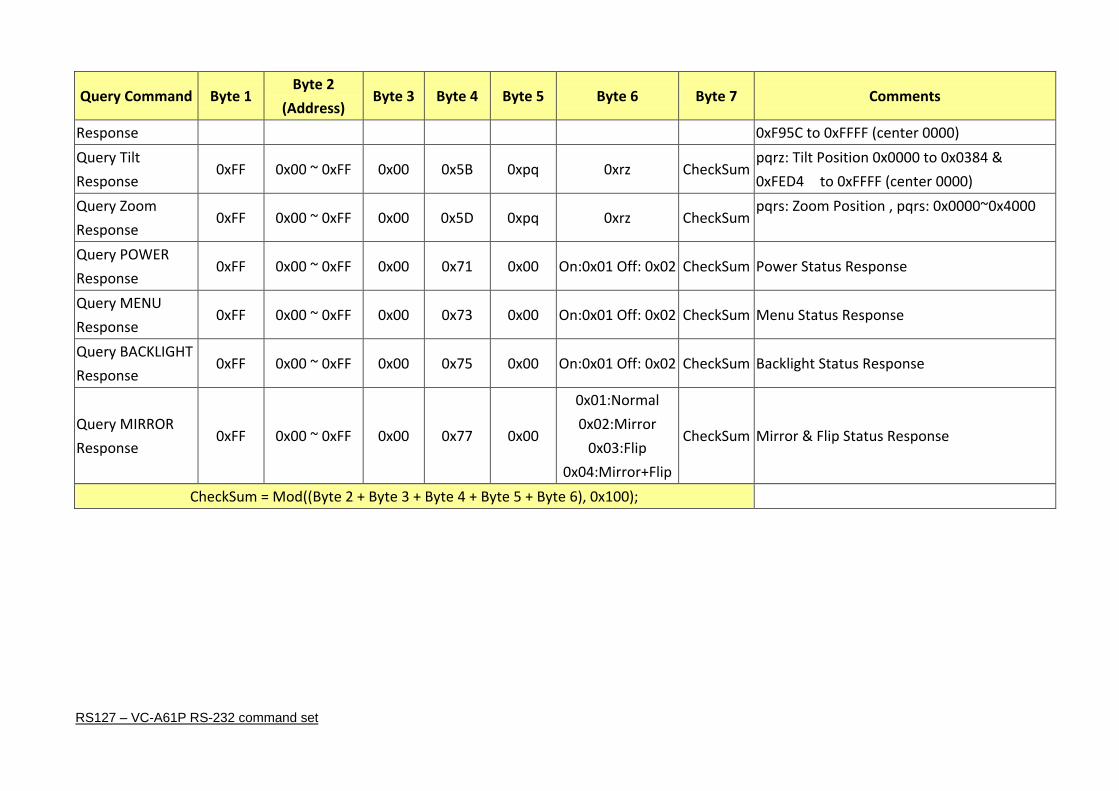
16.2 Query Command
Query Command Byte 1 Byte 2
(Address) Byte 3 Byte 4 Byte 5 Byte 6 Byte 7 Comments
Query Command Package
Query Zoom
Position 0xFF 0x00 ~ 0xFF 0x00 0x55 0x00 0x00 CheckSum Get Zoom Position
Query POWER 0xFF 0x00 ~ 0xFF 0x00 0x61 0x00 0x00 CheckSum Get Power On/Off Status
Query MENU 0xFF 0x00 ~ 0xFF 0x00 0x63 0x00 0x00 CheckSum Get Menu On/Off Status
Query BACKLIGHT 0xFF 0x00 ~ 0xFF 0x00 0x65 0x00 0x00 CheckSum Get Backlight On/Off Status
Query MIRROR 0xFF 0x00 ~ 0xFF 0x00 0x67 0x00 0x00 CheckSum Get Mirror & Flip Status
Query FREEZE 0xFF 0x00 ~ 0xFF 0x00 0x69 0x00 0x00 CheckSum Get Freeze Status
Query Ack Package
Query Pan 0xFF 0x00 ~ 0xFF 0x00 0x59 0xpq 0xrz CheckSum pqrz: Pan Position 0x0000 to 0x06A4 &
RS127 – VC-A61P RS-232 command set
Query Command Byte 1 Byte 2
(Address) Byte 3 Byte 4 Byte 5 Byte 6 Byte 7 Comments
Response 0xF95C to 0xFFFF (center 0000)
Query Tilt
Response 0xFF 0x00 ~ 0xFF 0x00 0x5B 0xpq 0xrz CheckSum
pqrz: Tilt Position 0x0000 to 0x0384 &
0xFED4 to 0xFFFF (center 0000)
Query Zoom
Response 0xFF 0x00 ~ 0xFF 0x00 0x5D 0xpq 0xrz CheckSum
pqrs: Zoom Position , pqrs: 0x0000~0x4000
Query POWER
Response 0xFF 0x00 ~ 0xFF 0x00 0x71 0x00 On:0x01 Off: 0x02 CheckSum Power Status Response
Query MENU
Response 0xFF 0x00 ~ 0xFF 0x00 0x73 0x00 On:0x01 Off: 0x02 CheckSum Menu Status Response
Query BACKLIGHT
Response 0xFF 0x00 ~ 0xFF 0x00 0x75 0x00 On:0x01 Off: 0x02 CheckSum Backlight Status Response
Query MIRROR
Response 0xFF 0x00 ~ 0xFF 0x00 0x77 0x00
0x01:Normal
0x02:Mirror
0x03:Flip
0x04:Mirror+Flip
CheckSum Mirror & Flip Status Response
CheckSum = Mod((Byte 2 + Byte 3 + Byte 4 + Byte 5 + Byte 6), 0x100);