vc a20p vc a202p rs 232 command set - lumens - vc...vc-a20p_vc-a202p rs-232 command set. ......
TRANSCRIPT

RS072 - VC-A20P_A202P RS-232 command set
VC-A20P_VC-A202P
RS-232 command set
No Issue Date Description Apply Firmware
1 2014/09/22 First version. VCT101
2 2014/11/24 Add VC-A202P which has same command set with VC-A20P NA
3 2015/04/07 Add 17. RS232 over IP VCT107
4 2015/05/14
1. Delete command: Power_LoadState/Power_LoadStateInq
2. Add Command: Pan/Tilt Speed table setting/ VISCA Camera command Table
VCT111
5 2015/11/12
1. Add Iris and Iris limit Table 2. Revise Optical Zoom & Focus range 3. Add Command:
3.1 Smooth Auto 3.2 CAM_SET_ETHERNET_DHCP 3.3 CAM_HARDWARE_FACTORY_RESET 3.4 CAM_MSDC_RESET
4. Revise Command: 4.1 CAM_WB_RGAIN: add range 4.2 CAM_WB_BGAIN: add range 4.3 AF SensitivityInq: correct the description
VCT119
6 2016/09/06 Add 20.9-21.14 for the communication method of VISCA over IP NA
7 2016/12/28 Revise the Shutter Table VCT129

RS072 - VC-A20P_A202P RS-232 command set
*Notice:
1. The RS-232 command list is for VC-A20P/ VC-A202P.
2. The yellow highlight means the latest update. 3. The blue highlight means the deleted item.

RS072 - VC-A20P_A202P RS-232 command set
3. ACK & Completion message
Reply Packet Note
Ack X0 4Y FF Y = socket number
Completion (commands) X0 5Y FF Y = socket number
Completion (Inquiries) X0 5Y ... FF Y = socket number
X = 9 to F==>camera address + 8 , Y=1 to 2
1. Communication Protocol
Transmit Method: Asynchronous Interface Half
Duplex Serial Communication
Transmit Speed: 9600bps or 38400bps
Start bit: 1Bit
Parity Check: NA
Data Bit: 8Bit
Stop Bit: 1Bit
2. The wire diagram
The RS232 wire diagram between presenter and
remote controller as below
RS072 - VC-A20P_A202P RS-232 command set
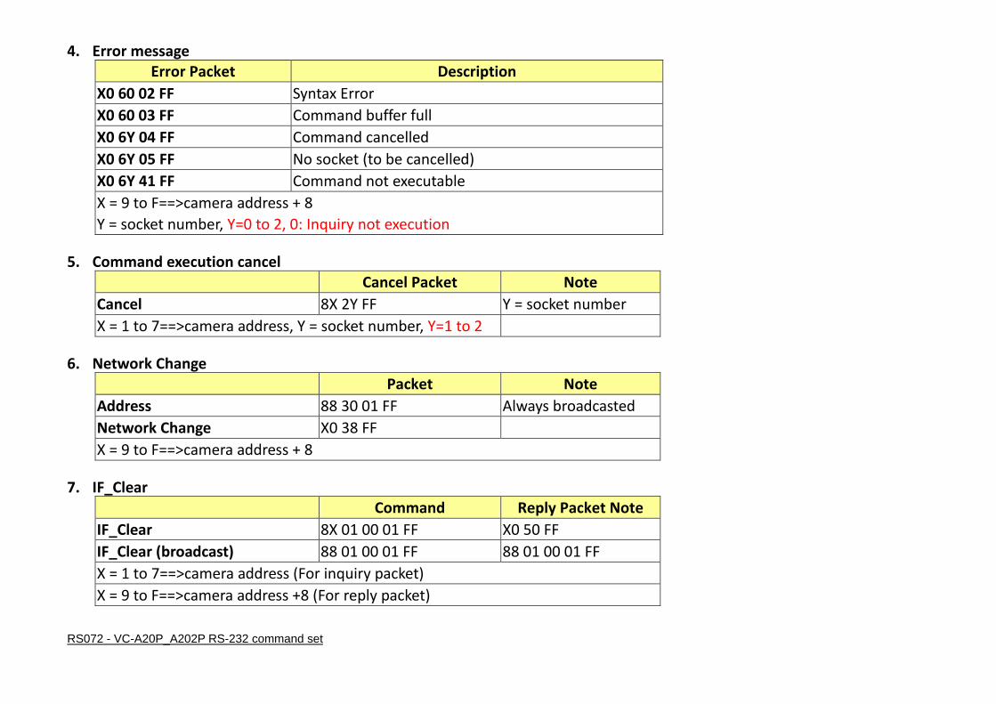
4. Error message Error Packet Description
X0 60 02 FF Syntax Error
X0 60 03 FF Command buffer full
X0 6Y 04 FF Command cancelled
X0 6Y 05 FF No socket (to be cancelled)
X0 6Y 41 FF Command not executable
X = 9 to F==>camera address + 8
Y = socket number, Y=0 to 2, 0: Inquiry not execution 5. Command execution cancel
Cancel Packet Note
Cancel 8X 2Y FF Y = socket number
X = 1 to 7==>camera address, Y = socket number, Y=1 to 2 6. Network Change
Packet Note
Address 88 30 01 FF Always broadcasted
Network Change X0 38 FF
X = 9 to F==>camera address + 8 7. IF_Clear
Command Reply Packet Note
IF_Clear 8X 01 00 01 FF X0 50 FF
IF_Clear (broadcast) 88 01 00 01 FF 88 01 00 01 FF
X = 1 to 7==>camera address (For inquiry packet)
X = 9 to F==>camera address +8 (For reply packet)

RS072 - VC-A20P_A202P RS-232 command set
8. Zoom Focus Position Table
Zoom Position
Wide end Optical Digital
Tele end Tele end
0x0000 to 0x4000 NULL
Focus Position Far end Near end
0x000 to 0x102 pqrs:0x000 ~ 0x102 9. Optical Zoom Position Table
Optical Zoom Ratio pqrs
x1 0x0000
x2 0x1C2B
x3 0x27A9
x4 0x2EC2
x5 0x33B7
x6 0x378C
x7 0x3A97
x8 0x3D12
x9 0x3EDF
x10 0x4000
RS072 - VC-A20P_A202P RS-232 command set
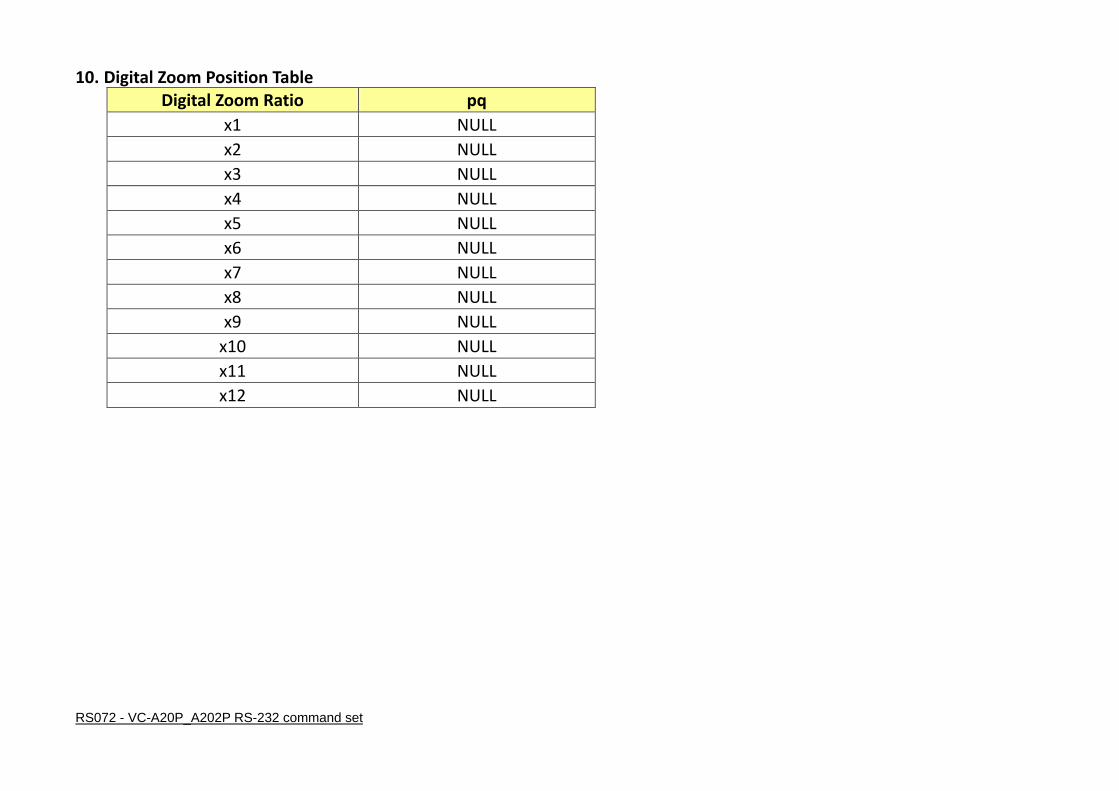
10. Digital Zoom Position Table
Digital Zoom Ratio pq
x1 NULL
x2 NULL
x3 NULL
x4 NULL
x5 NULL
x6 NULL
x7 NULL
x8 NULL
x9 NULL
x10 NULL
x11 NULL
x12 NULL

RS072 - VC-A20P_A202P RS-232 command set
11. AE_Shutter Table
Shutter Speed
Index(pq) 60/30 mode 50/25 mode
0x15 1/10000 1/10000
0x14 1/5000 1/5000
0x13 1/3000 1/3000
0x12 1/2500 1/2500
0x11 1/2000 1/1750
0x10 1/1500 1/1250
0x0F 1/1000 1/1000
0x0E 1/725 1/600
0x0D 1/500 1/425
0x0C 1/350 1/300
0x0B 1/250 1/215
0x0A 1/180 1/150
0x09 1/120 1/120
0x08 1/100 1/100
0x07 1/90 1/75
0x06 1/60 1/50
0x05 1/30 1/25
0x04 1/15 1/12
0x03 1/8 1/6
0x02 1/4 1/3
0x01 1/2 1/2
0x00 1/1 1/1

RS072 - VC-A20P_A202P RS-232 command set
12. AE_Iris Table
Iris
Index(pq) Value
0x0E F 1.8
0x0D F 2.1
0x0C F 2.5
0x0B F 3.0
0x0A F 3.6
0x09 F 4.3
0x08 F 5.1
0x07 F 6.1
0x06 F 7.2
0x05 F 8.6
0x04 F 10.2
0x03 F 12.1
0x02 F 14.4
0x01 F 17.1
0x00 F 20.4

RS072 - VC-A20P_A202P RS-232 command set
13. AE_Iris Limit Table
Iris
Index(pq) Value
0x07 F 1.8
0x06 F 2.5
0x05 F 3.6
0x04 F 5.1
0x03 F 7.2
0x02 F 10.2
0x01 F 14.4
0x00 F 20.4

RS072 - VC-A20P_A202P RS-232 command set
14. AE_Gain Table
Gain
Index(pq) Value
0x0F +30 dB
0x0E +28 dB
0x0D +26 dB
0x0C +24 dB
0x0B +22 dB
0x0A +20 dB
0x09 +18 dB
0x08 +16 dB
0x07 +14 dB
0x06 +12 dB
0x05 +10 dB
0x04 +8 dB
0x03 +6 dB
0x02 +4 dB
0x01 +2 dB
0x00 0 dB
15. AE_Gain Limit Table
Gain
Index(p) Value
0x0F +30 dB
0x0E +28 dB
0x0D +26 dB
0x0C +24 dB
0x0B +22 dB
0x0A +20 dB
0x09 +18 dB
0x08 +16 dB
0x07 +14 dB
0x06 +12 dB
0x05 +10 dB
0x04 +8 dB

RS072 - VC-A20P_A202P RS-232 command set
16. AE_Exposure Comp. Table
Exposure Comp.
Index(p) Value(Level)
0x0B 5
0x0A 4
0x09 3
0x08 2
0x07 1
0x06 0
0x05 -1
0x04 -2
0x03 -3
0x02 -4
0x01 -5
0x00 -6

RS072 - VC-A20P_A202P RS-232 command set
17. Camera Command List
Command Set Command Command Packet Comments
AddressSet Broadcast 88 30 01 FF Address setting
IF_Clear Broadcast 88 01 00 01 FF I/F Clear
CommandCancel – 8x 2p FF p: Socket No. (=1 or 2)
CAM_Power On 8x 01 04 00 02 FF Power ON/OFF
Off (Standby) 8x 01 04 00 03 FF
CAM_AutoPowerOff Direct 8x 01 04 40 0p 0q 0r 0s FF Auto Power Off, pqrs: 0000 To FFFF
pqrs: Power Off Timer 0000 (Timer Off) to FFFF
(65535min)
Initial value: 0000
The power automatically turns off if the camera does not
receive any VISCA commands or any signals from the
Remote Commander for the duration you set in the timer.
CAM_Zoom Stop 8x 01 04 07 00 FF
Tele (Standard) 8x 01 04 07 02 FF
Wide (Standard) 8x 01 04 07 03 FF
Tele Step 8x 01 04 07 04 FF
Wide Step 8x 01 04 07 05 FF
Tele (Variable) 8x 01 04 07 2p FF p=0 (Low) to 7 (High)
Wide (Variable) 8x 01 04 07 3p FF
Direct 8x 01 04 47 0p 0q 0r 0s FF pqrs: Zoom Position(0x0000~0x4000) , Optical Zoom Tele
max position: 0x4000

RS072 - VC-A20P_A202P RS-232 command set
Command Set Command Command Packet Comments
Direct(Speed Variable) 8x 01 04 47 0p 0q 0r 0s 0t FF pqrs: Zoom Position(0x0000~0x4000) , Optical Zoom Tele
max position: 0x4000, t:0~7(0 :Low, 7:High)
CAM_Focus Stop 8x 01 04 08 00 FF p=0 (Low) to 7 (High)
(* Enabled during Manual Focus Mode) Far (Standard) 8x 01 04 08 02 FF
Near (Standard) 8x 01 04 08 03 FF
Far Step 8x 01 04 08 04 FF
Near Step 8x 01 04 08 05 FF
Far (Variable) 8x 01 04 08 2p FF
Near (Variable) 8x 01 04 08 3p FF
Direct 8x 01 04 48 0p 0q 0r 0s FF pqrs: Focus Position , pqrs parameters are in the General
Zoom Foucs Table 0x00 ~ 0x102
(* Enabled during Manual Focus Mode)
Auto Focus 8x 01 04 38 02 FF AF ON/OFF
Manual Focus 8x 01 04 38 03 FF
Auto/Manual 8x 01 04 38 10 FF
One Push Trigger 8x 01 04 18 01 FF One Push AF Trigger(* Enabled during Manual Focus
Mode)
CAM_ZoomFocus Direct 8x 01 04 47 0p 0q 0r 0s 0t 0u 0v 0w
FF
pqrs: Zoom Position(0x0000~0x4000) tuvw: Focus
Position(0x00 ~ 0x102)
(* Enabled during Manual Focus Mode)

RS072 - VC-A20P_A202P RS-232 command set
Command Set Command Command Packet Comments
Resolution Settting — 8x 01 06 35 00 0p FF p:
0x00:1080p-60
0x01:1080p-59.94
0x02:1080p-50
0x03:1080p-30
0x04:1080p-29.97
0x05:1080p-25
0x06:1080i-60
0x07:1080i-59.94
0x08:1080i-50
0x09:720p-60
0x0A:720p-59.94
0x0B:720p-50
CAM_WB Auto 8x 01 04 35 00 FF Normal Auto
Indoor 8x 01 04 35 01 FF Indoor mode
Outdoor 8x 01 04 35 02 FF Outdoor mode
One Push WB 8x 01 04 35 03 FF One Push WB mode
ATW 8x 01 04 35 04 FF Auto Tracing White Balance
Manual 8x 01 04 35 05 FF Manual mode
Sodium Lamp 8x 01 04 35 06 FF Sodium lamp source fixed mode
3000K 8x 01 04 35 07 FF Color temperture fixed at 3000K mode
4300K 8x 01 04 35 08 FF Color temperture fixed at 4300K mode

RS072 - VC-A20P_A202P RS-232 command set
Command Set Command Command Packet Comments
5000K 8x 01 04 35 09 FF Color temperture fixed at 5000K mode
6500K 8x 01 04 35 0A FF Color temperture fixed at 6500K mode
8000K 8x 01 04 35 0B FF Color temperture fixed at 8000K mode
WideAuto 8x 01 04 35 0C FF Wide Auto mode
One Push Trigger 8x 01 04 10 05 FF One Push WB Trigger(* Enabled during One Push WB
Mode)
CAM_WB_RGAIN Reset 8x 01 04 03 00 FF Manual R gain Setting
(* Enabled during WB Manual mode )
pq = 0x00 To 0x80
Up 8x 01 04 03 02 FF
Down 8x 01 04 03 03 FF
Direct 8x 01 04 43 00 00 0p 0q FF
CAM_WB_BGAIN Reset 8x 01 04 04 00 FF Manual B gain Setting
(* Enabled during WB Manual mode )
pq = 0x00 To 0x80
Up 8x 01 04 04 02 FF
Down 8x 01 04 04 03 FF
Direct 8x 01 04 44 00 00 0p 0q FF
CAM_AE Full Auto 8x 01 04 39 00 FF Automatic Exposure mode
Manual 8x 01 04 39 03 FF Manual Control mode
Shutter Priority 8x 01 04 39 0A FF Shutter Priority Automatic Exposure mode
Iris Priority 8x 01 04 39 0B FF Iris Priority Automatic Exposure mode
White Board 8x 01 04 39 5F FF White Board Mode
Smooth Auto 8x 01 04 39 60 FF Smooth Auto
CAM_Shutter Reset 8x 01 04 0A 00 FF Shutter Setting
(* Enabled during AE Shutter Priority/Manaual Mode)
pq: Shutter Position , pq: 00 To 15
Up 8x 01 04 0A 02 FF
Down 8x 01 04 0A 03 FF
Direct 8x 01 04 4A 00 00 0p 0q FF
CAM_Iris Reset 8x 01 04 0B 00 FF Iris Setting

RS072 - VC-A20P_A202P RS-232 command set
Command Set Command Command Packet Comments
Up 8x 01 04 0B 02 FF (* Enabled during Iris Priority/Manaual Mode)
Down 8x 01 04 0B 03 FF
Direct 8x 01 04 4B 00 00 0p 0q FF pq: Iris Position , pq: 00 To0E
Iris Limit 8x 01 04 2B 0p FF p: Iris F number , p: 0 To 7 (* Disabled during AE
Manual Mode and IrisPri Mode)
CAM_Gain Reset 8x 01 04 0C 00 FF Gain Setting
(* Enabled during AE Manaual Mode) Up 8x 01 04 0C 02 FF
Down 8x 01 04 0C 03 FF
Direct 8x 01 04 4C 00 00 0p 0q FF pq: Gain Position, pq:00 To 0F (* Enabled during AE
Manaual Mode)
Gain Limit 8x 01 04 2C 0p FF p: Gain Position , p: 4 To F (* Disabled during AE
Manual Mode)
CAM_ExpComp On 8x 01 04 3E 02 FF Exposure Compensation ON/OFF
Off 8x 01 04 3E 03 FF
Reset 8x 01 04 0E 00 FF Exposure Compensation Amount Setting
(* Enabled during ExpComp On )
Up 8x 01 04 0E 02 FF
Down 8x 01 04 0E 03 FF
Direct 8x 01 04 4E 00 00 0p 0q FF pq: ExpComp Position , pq: 00 To 0B(* Enabled during
ExpComp On )
CAM_BackLight On 8x 01 04 33 02 FF Back Light Compensation ON/OFF
(* Enabled during AE Full Auto Mode)
Off 8x 01 04 33 03 FF

RS072 - VC-A20P_A202P RS-232 command set
Command Set Command Command Packet Comments
CAM_WD Set Parameter 8x 01 04 2D 0p FF WDR Mode p:0~5
CAM_Aperture
(Sharpness)
Reset 8x 01 04 02 00 FF Aperture Control
Up 8x 01 04 02 02 FF
Down 8x 01 04 02 03 FF
Direct 8x 01 04 42 00 00 0p 0q FF pq: Aperture Gain, pq: 00 To 0F
CAM_HR On 8x 01 04 52 02 FF High-Resolusion Mode ON/OFF
Off 8x 01 04 52 03 FF
CAM_2DNR — 8x 01 04 53 0p FF p: NR Setting , p: 0 To 6 (0: Auto,1:Off 6: Max )
CAM_3DNR — 8x 01 04 54 0p FF p: NR Setting , p: 0:Off 1:Low 2:Typ 3:Max 4:Auto
CAM_Gamma — 8x 01 04 5B 0p FF p: Gamma setting ,p: 0 To 3 (* Enabled during Image Mode
= Custom mode )
CAM_HighSensitivity On 8x 01 04 5E 02 FF High Sensitivity mode ON/OFF
Off 8x 01 04 5E 03 FF
CAM_LR_Reverse On 8x 01 04 61 02 FF Mirror Image ON/OFF
Off 8x 01 04 61 03 FF
CAM_Freeze On 8x 01 04 62 02 FF Still Image ON/OFF
Off 8x 01 04 62 03 FF
CAM_PictureEffect Off 8x 01 04 63 00 FF Picture Effect Setting
Neg.Art 8x 01 04 63 02 FF

RS072 - VC-A20P_A202P RS-232 command set
Command Set Command Command Packet Comments
B&W 8x 01 04 63 04 FF
CAM_PictureFlip On 8x 01 04 66 02 FF Picture flip ON/OFF
Off 8x 01 04 66 03 FF
CAM_Memory
(Preset)
Reset 8x 01 04 3F 00 pp FF pp: Memory Number (pp: 0x00 To 0x7F)
Set 8x 01 04 3F 01 pp FF
Recall 8x 01 04 3F 02 pp FF
CAM_Mute On 8x 01 04 75 02 FF Muting ON/OFF
Off 8x 01 04 75 03 FF
On/Off 8x 01 04 75 10 FF
CAM_IDWrite — 8x 01 04 22 0p 0q 0r 0s FF pqrs: Camera ID (=0000 to FFFF)
CAM_ColorGain(Saturation) Direct 8x 01 04 49 00 00 00 pq FF pq:0x00~0x19 (* Enabled during Image Mode = Custom
mode )
IR_Receive On 8x 01 06 08 02 FF IR(remote commander) receive ON/OFF
Off 8x 01 06 08 03 FF
On/Off 8x 01 06 08 10 FF
IR_ReceiveReturn On 8x 01 7D 01 03 00 00 FF IR (remote commander) receive message via the VISCA
communication ON/OFF Off 8x 01 7D 01 13 00 00 FF

RS072 - VC-A20P_A202P RS-232 command set
Command Set Command Command Packet Comments
Pan-tiltDrive Up 3) 8x 01 06 01 VV WW 03 01 FF VV: Pan speed 0x01 (low speed) to 0x18 (high speed) WW:
Tilt Speed 0x01 (low speed) to 0x18 (high speed)
VV: 00 To 0x18
WW: 00 To 0x18
YYYY: Pan Position 0x0000 to 0x3A80 & 0xC580 to
0xFFFF (center 0000)
ZZZZ: Tilt Position 0x0000 to 0x3DE0 & 0xEB60 to
0xFFFF (center 0000)
Down 3) 8x 01 06 01 VV WW 03 02 FF
Left 3) 8x 01 06 01 VV WW 01 03 FF
Right 3) 8x 01 06 01 VV WW 02 03 FF
UpLeft 3) 8x 01 06 01 VV WW 01 01 FF
UpRight 3) 8x 01 06 01 VV WW 02 01 FF
DownLeft 3) 8x 01 06 01 VV WW 01 02 FF
DownRight 3) 8x 01 06 01 VV WW 02 02 FF
Stop 3) 8x 01 06 01 VV WW 03 03 FF
AbsolutePosition 8x 01 06 02 VV WW 0Y 0Y 0Y 0Y 0Z
0Z 0Z 0Z FF
RelativePosition 8x 01 06 03 VV WW 0Y 0Y 0Y 0Y 0Z
0Z 0Z 0Z FF
Home 8x 01 06 04 FF
Reset 8x 01 06 05 FF
Pan-tiltLimitSet LimitSet 8x 01 06 07 00 0W 0Y 0Y 0Y 0Y 0Z 0Z
0Z 0Z FF
W: 1 UpRight YYYY: Pan Limit Position 0x0000~0x3A80
ZZZZ: Tilt Limit Position 0x0000~0x3DE0
W: 0 DownLeft YYYY: Pan Limit Position 0xFFFF~0xC580 LimitClear 8x 01 06 07 01 0W 07 0F 0F 0F 07 0F

RS072 - VC-A20P_A202P RS-232 command set
Command Set Command Command Packet Comments
0F 0F FF ZZZZ: Tilt Limit Position 0xFFFF~0xEB60
Firmware Firmware version 8x 01 02 03 FF
Error Code Read Error Code 8x 01 01 01 FF
Clear Error Code Record 8x 02 02 02 FF
Factory Reset System Factroy Reset 8x 01 04 3F 03 00 FF
CAM_Image_Mode Select CAM Image
Mode
8x 01 04 3F 04 0p FF p: 0~6, 6:Custom mode
CAM Prompt Set Prompt On/Off 8x 01 04 07 00 0p FF p: 2 to 3, 2:Prompt On , 3:Prompt Off
CAM Model ID Set Camera model ID 8x 01 04 23 pp qq rr ss FF ppqq: Vender ID , rrss:Model ID, default: HD1
AF Speed Normal 8x 01 04 56 02 FF
Set anytime AF speed : Normal / Fast Fast 8x 01 04 56 03 FF
AF Sensitivity - 8x 01 04 58 0p FF p: 1 to 3, 1:High , 2:Middle, 3:Low
CAM_ImageModeBrightness Set Brightness 8x 01 04 75 67 pq FF
pq: 0x00~0x19(* Enabled during Image Mode = Custom
mode )
CAM_ImageModeContrast Set Contrast 8x 01 04 75 68 pq FF
pq: 0x00~0x19(* Enabled during Image Mode = Custom
mode )
CAM_Skin_Tone select red level 8x 01 04 75 06 0p FF p: 0~5(* Enabled during Image Mode = Custom mode )
Black Level Black Level
8x 01 04 75 69 0p FF
p: 0 to 5, 0:Off, 1:Type 1, 2:Type 2, 3:Type 3, 4:Type 4,
5:Type 5
(* Enabled during Image Mode = Custom mode )
SYS_Menu On 8x 01 06 06 02 FF turn on the menu screen
Off 8x 01 06 06 03 FF turn off the menu screen
On/Off 8x 01 06 06 10 FF turn on/off the menu screen
Pan speed table update
command
- 8x 01 06 1A 0p 0q 0r 0s 0u 0v FF pqrs: 0x0 ~ 0xFFFF , uv: 0x0 ~ 0x63
Tilt speed table update - 8x 01 06 1B 0p 0q 0r 0s 0u 0v FF pqrs: 0x0 ~ 0xFFFF , uv: 0x0 ~ 0x63

RS072 - VC-A20P_A202P RS-232 command set
Command Set Command Command Packet Comments
command
Pan/Tilt speed table to
default
- 8x 01 06 1C 0p 0q 0D 0E 0F FF pq: 0x18 or 0x64
Pan/tilt speed table size - 8x 01 06 1D 0p 0q FF pq: 0x18 or 0x64
Pan/tilt speed table save - 8x 01 06 1E FF
CAM_SET_ETHERNET_DHCP Ethernet DHCP
Enable/Disable 8x 01 CC 0p FF p: 0~1 , 0: Disable 1: Enable
CAM_HARDWARE_FACTORY
_RESET
System Hardware
Factory Reset 8x 01 CD 0p FF p: 1, 1: Enable
CAM_MSDC_RESET MSDC Storage Reset 8x 01 CE 0p FF p: 1, 1: Enable

RS072 - VC-A20P_A202P RS-232 command set
18. Inquiry Command List
Inquiry Command Command Packet Inquiry Packet Comments
CAM_PowerInq 8x 09 04 00 FF y0 50 02 FF On
y0 50 03 FF Off (Standby)
CAM_OpticalZoomPosInq 8x 09 04 47 FF y0 50 0p 0q 0r 0s FF pqrs: Zoom Position , pqrs: 0x0000~0x4000
CAM_FocusModeInq 8x 09 04 38 FF y0 50 02 FF Auto Focus
y0 50 03 FF Manual Focus
CAM_FocusPosInq 8x 09 04 48 FF y0 50 0p 0q 0r 0s FF pqrs: Focus Position, pqrs: 0x000 to 0x102
Resolution SetttingInq 8x 09 06 23 FF y0 50 0p FF p:
0x00:1080p-60
0x01:1080p-59.94
0x02:1080p-50
0x03:1080p-30
0x04:1080p-29.97
0x05:1080p-25
0x06:1080i-60
0x07:1080i-59.94
0x08:1080i-50
0x09:720p-60
0x0A:720p-59.94
0x0B:720p-50
CAM_WBModeInq 8x 09 04 35 FF y0 50 00 FF Auto
y0 50 01 FF In Door
y0 50 02 FF Out Door
y0 50 03 FF One Push WB
y0 50 04 FF ATW

RS072 - VC-A20P_A202P RS-232 command set
Inquiry Command Command Packet Inquiry Packet Comments
y0 50 05 FF Manual
y0 50 06 FF Sodium Lamp
y0 50 07 FF 3000K
y0 50 08 FF 4300K
y0 50 09 FF 5000K
y0 50 0A FF 6500K
y0 50 0B FF 8000K
y0 50 0C FF Wide Auto
CAM_AEModeInq 8x 09 04 39 FF y0 50 00 FF Full Auto
y0 50 03 FF Manual
y0 50 0A FF Shutter Priority
y0 50 0B FF Iris Priority
y0 50 5F FF White Board
y0 50 60 FF Smooth Auto
CAM_ShutterPosInq 8x 09 04 4A FF y0 50 00 00 0p 0q FF pq: Shutter Position, pq: 00 To 15
CAM_IrisPosInq 8x 09 04 4B FF y0 50 00 00 0p 0q FF pq: Iris Position, pq: 00 To 0E
CAM_GainPosInq 8x 09 04 4C FF y0 50 00 00 0p 0q FF pq: Gain Position, pq: 00 To 0F
CAM_IrisLimitInq 8x 09 04 2B FF y0 50 0q FF p: Gain Limit,p: 0 To 7
CAM_GainLimitInq 8x 09 04 2C FF y0 50 0q FF p: Gain Limit,p: 4 To F
CAM_ExpCompModeInq 8x 09 04 3E FF y0 50 02 FF On
y0 50 03 FF Off
CAM_ExpCompPosInq 8x 09 04 4E FF y0 50 00 00 0p 0q FF pq: ExpComp Position, pq: 00 To 0B
CAM_BackLightModeInq 8x 09 04 33 FF y0 50 02 FF On
y0 50 03 FF Off
CAM_WDModeInq 8x 09 04 3D FF y0 50 02 FF On Wide-D

RS072 - VC-A20P_A202P RS-232 command set
Inquiry Command Command Packet Inquiry Packet Comments
y0 50 03 FF Off
CAM_WDParameterInq 8x 09 04 2D FF y0 50 0p FF p: WDR mode off/mid/max(p: 0 To 5)
CAM_ApertureInq 8x 09 04 42 FF y0 50 00 00 0p 0q FF pq: Aperture Gain, pq: 00 To 0F
CAM_HRModeInq 8x 09 04 52 FF y0 50 02 FF On (Hi-Resolution)
y0 50 03 FF Off
CAM_2DNRModeInq 8x 09 04 53 FF y0 50 0p FF p: NR Setting , p: 0 To 6 (0: Auto,1:Off 6: Max )
CAM_3DNRModeInq 8x 09 04 54 FF y0 50 0p FF p: NR Setting , p: 0:Off 1:Low 2:Typ 3:Max 4:Auto
CAM_GammaInq 8x 09 04 5B FF y0 50 0p FF Gamma p: 0 To 3
CAM_HighSensitivityInq 8x 09 04 5E FF y0 50 02 FF On
y0 50 03 FF Off
CAM_LR_ReverseModeInq 8x 09 04 61 FF y0 50 02 FF On
y0 50 03 FF Off
CAM_FreezeModeInq 8x 09 04 62 FF y0 50 02 FF On
y0 50 03 FF Off
CAM_PictureEffectModeInq 8x 09 04 63 FF y0 50 00 FF Off
y0 50 02 FF Neg.Art
y0 50 04 FF B&W
CAM_PictureFlipModeInq 8x 09 04 66 FF y0 50 02 FF On
y0 50 03 FF Off
CAM_MemoryInq 8x 09 04 3F FF y0 50 pp FF pp: Memory number recalled last, default value(no get any
recall command) pp:0x00 To 0x7F
CAM_MemSaveInq 8x 09 04 23 0X FF y0 50 0p 0p 0q 0q FF X: 00 to 07 (Address)
ppqq: 0x0000 to 0xFFFF (Data)
CAM_MuteModeInq 8x 09 04 75 FF y0 50 02 FF On
y0 50 03 FF Off

RS072 - VC-A20P_A202P RS-232 command set
Inquiry Command Command Packet Inquiry Packet Comments
CAM_IDInq 8x 09 04 22 FF y0 50 0p 0q 0r 0s FF pqrs: Camera ID, pqrs: 0000 To FFFF
CAM_ColorGainInq 8x 09 04 49 FF y0 50 00 00 00 pq FF pq: Color Gain setting , pq: 0x00 To 0x19
SYS_MenuModeInq 8x 09 06 06 FF y0 50 02 FF On
y0 50 03 FF Off
IR_Receive 8x 09 06 08 FF y0 50 02 FF On
y0 50 03 FF Off
IR_ReceiveReturn 8x 01 7D 01 03 00 00 FF
(IR_Receive Return
Message On)
y0 07 7D 01 04 00 FF Power ON/OFF
y0 07 7D 01 04 07 FF Zoom tele/wide
y0 07 7D 01 04 38 FF AF On/Off
y0 07 7D 01 04 33 FF CAM_Backlight
y0 07 7D 01 04 3F FF CAM_Memory(All memory set)
y0 07 7D 01 06 01 FF Pan_tiltDrive
Pan-tiltMaxSpeedInq 8x 09 06 11 FF y0 50 ww zz FF ww = Pan Max Speed, ww: 0x18
zz = Tilt Max Speed, zz: 0x18
Pan-tiltPosInq 8x 09 06 12 FF y0 50 0w 0w 0w 0w 0z 0z 0z 0z FF wwww:【0x0000 To 0x3A80】 or 【0xFFFF To 0xC580】
zzzz: 【0x0000 To 0x3DE0】 or 【0xFFFF To 0xEB60】
wwww = Pan Position
zzzz = Tilt Position
Pan-tiltModeInq 8x 09 06 10 FF y0 50 pq rs FF pqrs: 0000 To FFFF, see the General Pan Tilt Mode Status
Table
CAM Image ModeInq 8x 09 04 3F 04 FF y0 50 0p FF p:0 To 6
Prompt Inq 8x 09 04 07 00 FF y0 50 0p FF Prompt OnOff 2:On,3:Off
CAM Version Inq 8x 09 00 02 FF y0 50 pp qq rr ss jj jj kk FF ppqq: Vender ID,rrss: Model ID,jjjj: Rom revision,kk:

RS072 - VC-A20P_A202P RS-232 command set
Inquiry Command Command Packet Inquiry Packet Comments
Maxinum socket
AF SensitivityInq 8x 09 04 58 FF y0 50 00 00 00 0p FF p: 1 to 3, 1:High , 2:Middle, 3:Low
CAM_AF Speed Inq 8x 09 04 56 FF y0 50 02 FF Normal
y0 50 03 FF Fast
BlackLevelInq 8x 09 04 75 69 FF y0 50 0p FF p: 0 to 5, 0:Off, 1:Type 1, 2:Type 2, 3:Type 3,4:Type
4,5:Type 5
Pan speed table inq 8x 09 06 1A 0p 0q FF y0 50 0p 0q 0r 0s FF pq: 0x0 ~ 0x63, pqrs: 0x0 ~ 0xFFFF
Tilt speed table inq 8x 09 06 1B 0p 0q FF y0 50 0p 0q 0r 0s FF pq: 0x0 ~ 0x63, pqrs: 0x0 ~ 0xFFFF
RS072 - VC-A20P_A202P RS-232 command set
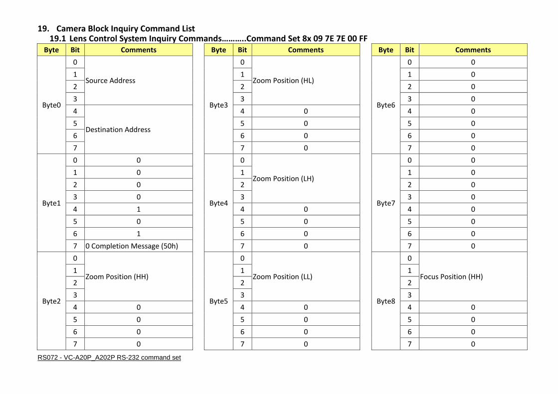
19. Camera Block Inquiry Command List 19.1 Lens Control System Inquiry Commands………..Command Set 8x 09 7E 7E 00 FF
Byte Bit Comments
Byte0
0
Source Address 1
2
3
4
Destination Address 5
6
7
Byte1
0 0
1 0
2 0
3 0
4 1
5 0
6 1
7 0 Completion Message (50h)
Byte2
0
Zoom Position (HH) 1
2
3
4 0
5 0
6 0
7 0
Byte Bit Comments
Byte3
0
Zoom Position (HL) 1
2
3
4 0
5 0
6 0
7 0
Byte4
0
Zoom Position (LH) 1
2
3
4 0
5 0
6 0
7 0
Byte5
0
Zoom Position (LL) 1
2
3
4 0
5 0
6 0
7 0
Byte Bit Comments
Byte6
0 0
1 0
2 0
3 0
4 0
5 0
6 0
7 0
Byte7
0 0
1 0
2 0
3 0
4 0
5 0
6 0
7 0
Byte8
0
Focus Position (HH) 1
2
3
4 0
5 0
6 0
7 0

RS072 - VC-A20P_A202P RS-232 command set
Byte Bit Comments
Byte9
0
Focus Position (HL) 1
2
3
4 0
5 0
6 0
7 0
Byte10
0
Focus Position (LH) 1
2
3
4 0
5 0
6 0
7 0
Byte11
0
Focus Position (LL) 1
2
3
4 0
5 0
Byte Bit Comments
6 0
7 0
Byte12
0 0
1 0
2 0
3 0
4 0
5 0
6 0
7 0
Byte13
0 Focus Mode 0: Manual 1:
Auto
1 Digital Zoom 1: On 0: Off
2 0
3 0
4 0
5 0
Byte Bit Comments
6 0
7 0
Byte14
0 Zoom Command 1: Executing
0: Stopped
1 Focus Command 1: Executing
0: Stopped
2 Camera Memory Recall 1:
Executing 0: Stopped
3 0
4 0
5 0
6 0
7 0
Byte15
0 1
1 1
2 1
3 1
4 1
5 1
6 1
7 1 Terminator (FFh)

RS072 - VC-A20P_A202P RS-232 command set
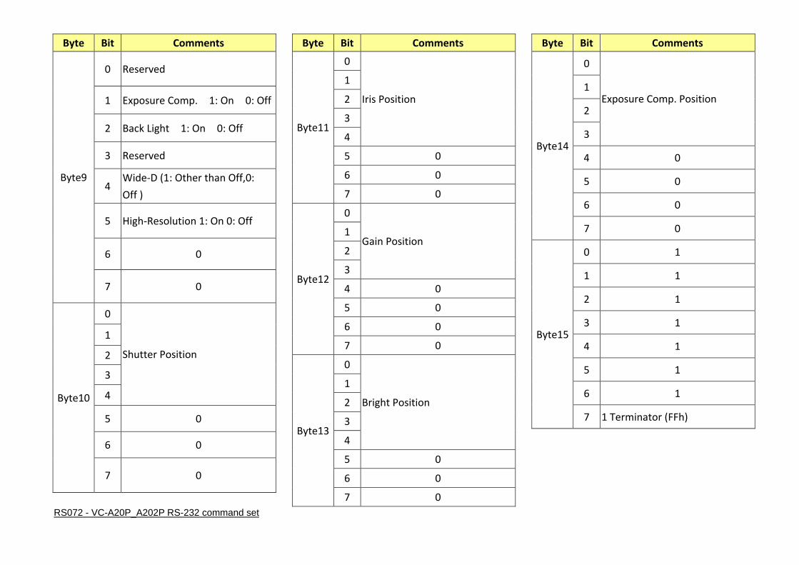
19.2 Camera Control System Inquiry Commands………..Command Set 8x 09 7E 7E 01 FFByte Bit Comments
Byte0
0
Source Address 1
2
3
4
Destination Address 5
6
7
Byte1
0 0
1 0
2 0
3 0
4 1
5 0
6 1
7 0 Completion Message (50h)
Byte2
0
R Gain (H) 1
2
3
4 0
5 0
6 0
7 0
Byte Bit Comments
Byte3
0
R Gain (L) 1
2
3
4 0
5 0
6 0
7 0
Byte4
0
B Gain (H) 1
2
3
4 0
5 0
6 0
7 0
Byte5
0
B Gain (L) 1
2
3
4 0
5 0
6 0
7 0
Byte Bit Comments
Byte6
0
WB Mode 1
2
3
4 0
5 0
6 0
7 0
Byte7
0
Aperture Gain 1
2
3
4 0
5 0
6 0
7 0
Byte8
0
Exposure Mode
1
2
3
4
5
6 0
7 0
RS072 - VC-A20P_A202P RS-232 command set
Byte Bit Comments
Byte9
0 Reserved
1 Exposure Comp. 1: On 0: Off
2 Back Light 1: On 0: Off
3 Reserved
4 Wide-D (1: Other than Off,0:
Off )
5 High-Resolution 1: On 0: Off
6 0
7 0
Byte10
0
Shutter Position
1
2
3
4
5 0
6 0
7 0
Byte Bit Comments
Byte11
0
Iris Position
1
2
3
4
5 0
6 0
7 0
Byte12
0
Gain Position 1
2
3
4 0
5 0
6 0
7 0
Byte13
0
Bright Position
1
2
3
4
5 0
6 0
7 0
Byte Bit Comments
Byte14
0
Exposure Comp. Position 1
2
3
4 0
5 0
6 0
7 0
Byte15
0 1
1 1
2 1
3 1
4 1
5 1
6 1
7 1 Terminator (FFh)

RS072 - VC-A20P_A202P RS-232 command set
19.3 Other Inquiry Commands………..Command Set 8x 09 7E 7E 02 FF Byte Bit Comments
Byte0
0
Source Address 1
2
3
4
Destination Address 5
6
7
Byte1
0 0
1 0
2 0
3 0
4 1
5 0
6 1
7 0 Completion Message (50h)
Byte2
0 Power 1: On 0: Off
1 0
2 0
3 0
4 0
5 0
6 0
7 0
Byte Bit Comments
Byte3
0 0
1 0
2 LR Reverse 1: On 0: Off
3 Freeze 1: On 0: Off
4 ICR 1: On 0: Off
5 0
6 0
7 0
Byte4
0 0
1 0
2 0
3 0
4 Mute 1: On 0: Off
5 0
6 0
7 0
Byte5
0
Picture Effect Mode 1
2
3
4 0
5 0
6 0
7 0
Byte Bit Comments
Byte6
0 0
1 0
2 0
3 0
4 0
5 0
6 0
7 0
Byte7
0 0
1 0
2 0
3 0
4 0
5 0
6 0
7 0
Byte8
0
Camera ID (HH) 1
2
3
4 0
5 0
6 0
7 0

RS072 - VC-A20P_A202P RS-232 command set
Byte Bit Comments
Byte9
0
Camera ID (HL) 1
2
3
4 0
5 0
6 0
7 0
Byte10
0
Camera ID (LH) 1
2
3
4 0
5 0
6 0
7 0
Byte Bit Comments
Byte11
0
Camera ID (LL) 1
2
3
4 0
5 0
6 0
7 0
Byte12
0 1: 1/50, 1/25 0: 1/60, 1/30
1 0
2 ICR 1: Provided 0: Not
provided
3 0
4 Memory 1: Provided 0: Not
provided
5 0
6 0
7 0
Byte13 0 0
Byte Bit Comments
1 0
2 0
3 0
4 0
5 0
6 0
7 0
Byte14
0 0
1 0
2 0
3 0
4 0
5 0
6 0
7 0
Byte15
0 1
1 1
2 1
3 1
4 1
5 1
6 1
7 1 Terminator (FFh)

RS072 - VC-A20P_A202P RS-232 command set
19.4 Enlargement Function1 Query Command………..Command Set 8x 09 7E 7E 03 FF Byte Bit Comments
Byte0
0
Source Address 1
2
3
4
Destination Address 5
6
7
Byte1
0 0
1 0
2 0
3 0
4 1
5 0
6 1
7 0 Completion Message (50h)
Byte2
0
Digital Zoom Position (H) 1
2
3
4 0
5 0
6 0
7 0
Byte Bit Comments
Byte3
0
Digital Zoom Position (L) 1
2
3
4 0
5 0
6 0
7 0
Byte4
0 0
1 0
2 0
3 0
4 0
5 0
6 0
7 0
Byte5
0 0
1 0
2 0
3 0
4 0
5 0
6 0
7 0
Byte Bit Comments
Byte6
0 0
1 0
2 0
3 0
4 0
5 0
6 0
7 0
Byte7
0 0
1 0
2 0
3 0
4 0
5 0
6 0
7 0
Byte8
0
Reserved 1
2
3
4 0
5 0
6 0
7 0

RS072 - VC-A20P_A202P RS-232 command set
Byte Bit Comments
Byte9
0
Reserved 1
2
3
4 0
5 0
6 0
7 0
Byte10
0 Picture flip (1: On, 0: Off )
1 Alarm (1: On, 0: Off )
2 0
3 0
4 0
5 0
6 0
7 0
Byte Bit Comments
Byte11
0 Picture flip (1: Provided, 0: Not
provided)
1 0
2 Advanced Privacy (1: Provided, 0:
Not provided)
3
Color Gain (0h (60%) to Eh
(200%))
4
5
6
7 0
Byte12
0 0
1 0
2 0
3 0
4 0
5 0
6 0
7 0
Byte Bit Comments
Byte13
0
2NR Level 1
2
3 High Sensitivity mode (1: ON, 0:
OFF)
4
Gamma 5
6
7 0
Byte14
0
Gain Limit 1
2
3
4
Reserved 5
6
7 0
Byte15
0 1
1 1
2 1
3 1
4 1
5 1
6 1
7 1 Terminator (FFh)
RS072 - VC-A20P_A202P RS-232 command set
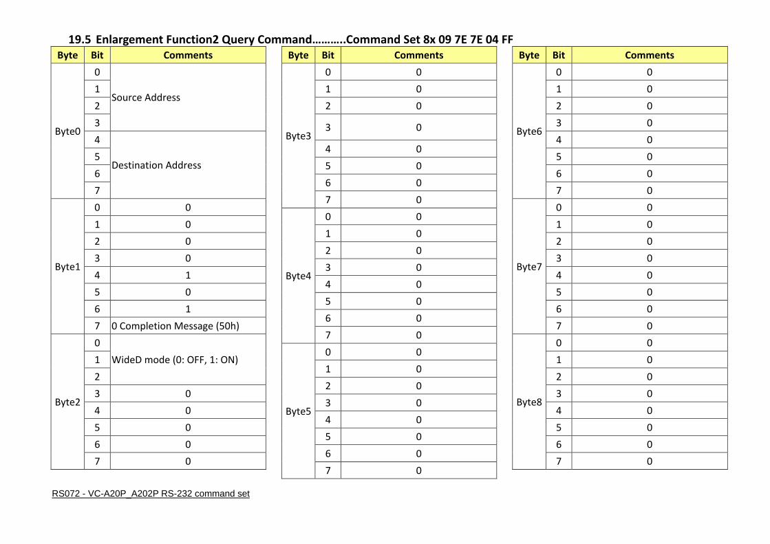
19.5 Enlargement Function2 Query Command………..Command Set 8x 09 7E 7E 04 FF Byte Bit Comments
Byte0
0
Source Address 1
2
3
4
Destination Address 5
6
7
Byte1
0 0
1 0
2 0
3 0
4 1
5 0
6 1
7 0 Completion Message (50h)
Byte2
0
WideD mode (0: OFF, 1: ON) 1
2
3 0
4 0
5 0
6 0
7 0
Byte Bit Comments
Byte3
0 0
1 0
2 0
3 0
4 0
5 0
6 0
7 0
Byte4
0 0
1 0
2 0
3 0
4 0
5 0
6 0
7 0
Byte5
0 0
1 0
2 0
3 0
4 0
5 0
6 0
7 0
Byte Bit Comments
Byte6
0 0
1 0
2 0
3 0
4 0
5 0
6 0
7 0
Byte7
0 0
1 0
2 0
3 0
4 0
5 0
6 0
7 0
Byte8
0 0
1 0
2 0
3 0
4 0
5 0
6 0
7 0

RS072 - VC-A20P_A202P RS-232 command set
Byte Bit Comments
Byte9
0 0
1 0
2 0
3 0
4 0
5 0
6 0
7 0
Byte10
0 0
1 0
2 0
3 0
4 0
5 0
6 0
7 0
Byte Bit Comments
Byte11
0 0
1 0
2 0
3 0
4 0
5 0
6 0
7 0
Byte12
0 0
1 0
2 0
3 0
4 0
5 0
6 0
7 0
Byte Bit Comments
Byte13
0 0
1 0
2 0
3 0
4 0
5 0
6 0
7 0
Byte14
0 0
1 0
2 0
3 0
4 0
5 0
6 0
7 0
Byte15
0 1
1 1
2 1
3 1
4 1
5 1
6 1
7 1 Terminator (FFh)

RS072 - VC-A20P_A202P RS-232 command set
19.6 Enlargement Function3 Query Command………..Command Set 8x 09 7E 7E 05 FF Byte Bit Comments
Byte0
0
Source Address 1
2
3
4
Destination Address 5
6
7
Byte1
0 0
1 0
2 0
3 0
4 1
5 0
6 1
7 0 Completion Message (50h)
Byte2
0
Reserved 1
2
3
4 0
5 0
6 0
7 0
Byte Bit Comments
Byte3
0
Reserved
1
2
3
4
5
6
7 0
Byte4
0
Reserved
1
2
3
4
5
6
7 0
Byte5
0
Reserved
1
2
3
4
5
6
7 0
Byte Bit Comments
Byte6
0
Reserved
1
2
3
4
5
6
7 0
Byte7
0
Reserved
1
2
3
4
5
6
7 0
Byte8
0
Reserved
1
2
3
4
5
6
7 0

RS072 - VC-A20P_A202P RS-232 command set
Byte Bit Comments
Byte9
0
Reserved
1
2
3
4
5
6
7 0
Byte10
0
Reserved
1
2
3
4
5
6
7 0
Byte Bit Comments
Byte11
0
Reserved
1
2
3
4
5
6
7 0
Byte12
0
Reserved
1
2
3
4
5
6
7 0
Byte Bit Comments
Byte13
0
Reserved
1
2
3
4
5
6
7 0
Byte14
0
Reserved
1
2
3
4
5
6
7 0
Byte15
0 1
1 1
2 1
3 1
4 1
5 1
6 1
7 1 Terminator (FFh)

RS072 - VC-A20P_A202P RS-232 command set
20. RS232 over IP 20.1 Overview of RS232 over IP
RS232 over IP allows you to control this unit from the controller with the IP communication function via the LAN by
using RS232.
You can connect up to 5 controllers simultaneously on one LAN segment.
The communication specifications of RS232 over IP are as follows:
20.2 Interface
RJ-45 10Base-T/100Base-TX (automatically discrimination)
20.3 Internet protocol
IPv4
20.4 Transport protocol
UDP
20.5 IP address
Set by the IP card setting command
20.6 Port address
52381
20.7 Delivery confirmation/Retransmission control
Depends on the application
20.8 Coverage
Limited dedicated network in the same segment without going through a bridge connection.
In this section, the device outputting commands, for example, a computer, is called the controller, and this unit and the
devices connected to the same LAN are called the peripheral device. In the connection using RS-232/RS-422, the
controllers and peripheral devices are connected to a one-direction ring. On the IP communication connection, the
controllers and peripheral devices are connected by star type through a LAN.

RS072 - VC-A20P_A202P RS-232 command set
RS232/RS422 connection IP communication connection
While the IP communication connection, the address of each device cannot be set in the RS232 message as it is because
the controllers and peripheral devices that are connected simultaneously are increased. In this case, addresses of the
controllers and peripheral devices that are set in the RS232 message are locked to 0 (for the controller) or 1 (for the
peripheral device).
20.9 Packet Structure
The basic unit of VISCA communication is called a packet [Pic.1]. The first byte of the packet is called the header and
comprises the sender’s and receiver’s addresses. For example, the header of the packet sent to the SRG assigned address
1 from the controller (address 0) is 81h in hexadecimal. The packet sent to the SRG assigned address 2 is 82h. In the
command list, as the header is 8X, input the address of the SRG to X. The header of the reply packet from the SRG
assigned address 1 is 90h. The packet from the SRG assigned address 2 is A0h.
Some of the setting commands for SRG can be sent to all devices at one time (broadcast)*. In the case of broadcast, the
header should be 88h in hexadecimal.

RS072 - VC-A20P_A202P RS-232 command set
When the terminator is FFh, it signifies the end of the packet.
*The broadcast function is not available for VISCA over IP.
Pic. 1 Packet structure
Note:
Pic. 1 shows the packet structure, while Pic.2 shows the actual waveform. Data flow will take place with the LSB first.

RS072 - VC-A20P_A202P RS-232 command set
Pic. 2 Actual waveform for 1 byte
21. Communication method of VISCA over IP
21.1 Communication method VISCA over IP can process the VISCA communication between the controllers and peripheral devices using the messages that can be identified on the LAN, and sends/receives them. Because of this, VISCA over IP is not concerned about the contents of the communication between the controllers and peripheral devices. However, the VISCA communication sequence is different, depending on the types, as follows. 21.2 VISCA command This is a command from the controller to the peripheral device. When the peripheral device receives this command,
Acknowledge is returned. After completing command processing, a completion notice is returned. This command uses the
socket of VISCA. The order of completion notices may be changed if the multiple commands are sent to the same peripheral
device. 21.3 VISCA inquiry This is an inquiry from the controller to the peripheral device. When the peripheral device receives this type of command,
the reply for the inquiry is returned. This command does not use the socket of VISCA. The order of the replies is not changed
if a multiple commands are sent.
RS072 - VC-A20P_A202P RS-232 command set
21.4 VISCA reply This is an Acknowledge, completion notice, reply, or error reply from the peripheral device to the controller. The
classification for sending messages from the peripheral device to the controller is common.
21.5 VISCA device setting command This is the device setting command from the controller to the peripheral device. When the peripheral device receives this
classifications command, the peripheral device performs the function depend on the command. 21.6 Address Sets the address of the peripheral device, and does not return a reply to the controller. While using VISCA over IP, the
address command is not sent from the controller because a Network Change command from the peripheral device that
triggers sending command is not issued.
21.7 IF_Clear Sends the reply message to the controller after clearing, without using VISCA socket. 21.8 CAM_VerslonInq Sends the reply message to the controller, without using VISCA socket. 21.9 Format These are the specifications of the message header (8 bytes) and payload (1 to 16 bytes).
.

RS072 - VC-A20P_A202P RS-232 command set
Note: The actual LAN out method is big-endian, LSB first.
Pic.3 Message structure of the VISCA over IP
21.10 Payload type Stores the value (Byte 0 and Byte 1) of the following table on the payload division.
Pic.4 Payload Type Table

RS072 - VC-A20P_A202P RS-232 command set
21.11 Payload length Stores the number of bytes (1 to 16) of data is stored on the payload. Example: when the payload length is 16 bytes. Byte 2:00h Byte 3:10h 21.12 Sequence number The controller stores the sequence number that is added every time a message is sent. If the sequence number reaches the limit, next values will be 0. The peripheral device saves the sequence number in the message from the controller, and stores the sequence number of the received message corresponding to the message sent to the controller. 21.13 Payload
Depending on the payload type, the following are stored.
VISCA command Stores the packet of the VISCA command.
VISCA inquiry Stores the packet of VISCA message.
VISCA reply Stores the reply for the command or inquiry (Acknowledge message, completion message, or error message).
VISCA device setting command Stores the packet of the VISCA device setting command.
Control command The following are stored on the payload division of the control command.

RS072 - VC-A20P_A202P RS-232 command set
Controlled reply
The following are stored on the payload division of the reply for the control command.
21.14 Delivery confirmation VISCA over IP uses UDP as a communications protocol of the transport layer. Delivery of messages is not guaranteed for the UDP communication. Delivery confirmation and retransmission should be performed on the application. When the controller sends a message to the peripheral device, wait until a reply for the message is received before sending the next message. You can confirm delivery of messages by managing the time-out waiting for a reply message sent. If time out occurs on the controller, loss of one of the following message is considered: Command Acknowledge message Completion message for command Inquiry Reply message for the inquiry Error message Inquiry of the VISCA device setting command Reply message of the VISCA device setting command.

RS072 - VC-A20P_A202P RS-232 command set
22. PelcoD Internal Command List
Internal
Command Byte 1
Byte 2
(Address) Byte 3 Byte 4 Byte 5 Byte 6 Byte 7 Comments
Right 0xFF 0x00 ~ 0xFF 0x00 0x02 0xVV 0xWW CheckSum VV : Tilt speed 0x01 (low speed) to 0x18
(high speed) ,0x19 ~ 0xFE (speed follow
zoom position)
WW : Pan speed 0x01 (low speed) to 0x18
(high speed) ,0x19 ~ 0xFE (speed follow
zoom position)
Left 0xFF 0x00 ~ 0xFF 0x00 0x04 0xVV 0xWW CheckSum
Up 0xFF 0x00 ~ 0xFF 0x00 0x08 0xVV 0xWW CheckSum
Down 0xFF 0x00 ~ 0xFF 0x00 0x10 0xVV 0xWW CheckSum
Right - Up 0xFF 0x00 ~ 0xFF 0x00 0x0A 0xVV 0xWW CheckSum
Left - Up 0xFF 0x00 ~ 0xFF 0x00 0x0C 0xVV 0xWW CheckSum
Riight -Down 0xFF 0x00 ~ 0xFF 0x00 0x12 0xVV 0xWW CheckSum
Left - Down 0xFF 0x00 ~ 0xFF 0x00 0x14 0xVV 0xWW CheckSum
Stop 0xFF 0x00 ~ 0xFF 0x00 0x00 0x00 0x00 CheckSum Stop Pan/Tilt & Zomm/Focus
Zoom Tele 0xFF 0x00 ~ 0xFF 0x00 0x20 0x00 0x00 CheckSum Speed = VISCA Tele (Variable) = 0x03
Zoom Wide 0xFF 0x00 ~ 0xFF 0x00 0x40 0x00 0x00 CheckSum Speed = VISCA Wide (Variable) = 0x03
Focus Far 0xFF 0x00 ~ 0xFF 0x00 0x80 0x00 0x00 CheckSum Speed = VISCA Far (Variable) = 0x02
Focus Near 0xFF 0x00 ~ 0xFF 0x01 0x00 0x00 0x00 CheckSum Speed = VISCA Near (Variable) = 0x02
CheckSum = Mod((Byte 2 + Byte 3 + Byte 4 + Byte 5 + Byte 6), 0x100);
23. PelcoD External Command List
22.1 External Command
Extenal Command Byte 1 Byte 2
(Address) Byte 3 Byte 4 Byte 5 Byte 6 Byte 7 Comments
Set Preset 0xFF 0x00 ~ 0xFF 0x00 0x03 0x00 0xpq CheckSum Memory Number( pq:0x00 To 0x7F)
Clear Preset 0xFF 0x00 ~ 0xFF 0x00 0x05 0x00 0xpq CheckSum
Goto Preset 0xFF 0x00 ~ 0xFF 0x00 0x07 0x00 0xpq CheckSum
POWER 0xFF 0x00 ~ 0xFF 0x00 0x45 0x00 On:0x01
Off: 0x02 CheckSum Power On/Off
MENU 0xFF 0x00 ~ 0xFF 0x00 0x47 0x00 On:0x01 CheckSum System Menu On/Off

RS072 - VC-A20P_A202P RS-232 command set
Off: 0x02
ENTER 0xFF 0x00 ~ 0xFF 0x00 0x49 0x00 0x00 CheckSum Menu Enter
BACKLIGHT 0xFF 0x00 ~ 0xFF 0x00 0x31 0x00 On:0x01
Off: 0x02 CheckSum
Back Light Compensation ON/OFF
(* Enabled during AE Full Auto Mode)
MIRROR 0xFF 0x00 ~ 0xFF 0x00 0x4B 0x00
0x01:Normal
0x02:Mirror
0x03:Flip
0x04:Mirror+Flip
CheckSum Mirror Image ON/OFF & Picture flip ON/OFF
FREEZE 0xFF 0x00 ~ 0xFF 0x00 0x4D 0x00 On:0x01
Off: 0x02 CheckSum Still Image ON/OFF
Auto Focus /
Manual Focus 0xFF 0x00 ~ 0xFF 0x00 0x2B 0x00
AF:0x01
MF: 0x02 CheckSum AF/MF Switch
Bright Ctrl Up 0xFF 0x00 ~ 0xFF 0x00 0xA1 0x00 0x00 CheckSum AE Bright Control Up
Bright Ctrl Down 0xFF 0x00 ~ 0xFF 0x00 0xA3 0x00 0x00 CheckSum AE Bright Control Down
22.2 Query Command
Query Command Byte 1 Byte 2
(Address) Byte 3 Byte 4 Byte 5 Byte 6 Byte 7 Comments
Query Command Package
Query Pan
Position 0xFF 0x00 ~ 0xFF 0x00 0x51 0x00 0x00 CheckSum Get Pan Postion
Query Tilt
Position 0xFF 0x00 ~ 0xFF 0x00 0x53 0x00 0x00 CheckSum Get Tilt Postion
Query Zoom
Position 0xFF 0x00 ~ 0xFF 0x00 0x55 0x00 0x00 CheckSum Get Zoom Position
Query POWER 0xFF 0x00 ~ 0xFF 0x00 0x61 0x00 0x00 CheckSum Get Power On/Off Status
Query MENU 0xFF 0x00 ~ 0xFF 0x00 0x63 0x00 0x00 CheckSum Get Menu On/Off Status
Query BACKLIGHT 0xFF 0x00 ~ 0xFF 0x00 0x65 0x00 0x00 CheckSum Get Backlight On/Off Status

RS072 - VC-A20P_A202P RS-232 command set
Query Command Byte 1 Byte 2
(Address) Byte 3 Byte 4 Byte 5 Byte 6 Byte 7 Comments
Query MIRROR 0xFF 0x00 ~ 0xFF 0x00 0x67 0x00 0x00 CheckSum Get Mirror & Flip Status
Query FREEZE 0xFF 0x00 ~ 0xFF 0x00 0x69 0x00 0x00 CheckSum Get Freeze Status
Query Ack Package
Query Pan
Response 0xFF 0x00 ~ 0xFF 0x00 0x59 0xpq 0xrz CheckSum
pqrz: Pan Position 0x0000 to 0x3A80 &
0xC580 to 0xFFFF (center 0000)
Query Tilt
Response 0xFF 0x00 ~ 0xFF 0x00 0x5B 0xpq 0xrz CheckSum
pqrz: Tilt Position 0x0000 to 0x3DE0 &
0xEB60 to 0xFFFF (center 0000)
Query Zoom
Response 0xFF 0x00 ~ 0xFF 0x00 0x5D 0xpq 0xrz CheckSum
pqrs: Zoom Position , pqrs: 0x0000~0x4000
Query POWER
Response 0xFF 0x00 ~ 0xFF 0x00 0x71 0x00
On:0x01
Off: 0x02 CheckSum Power Status Response
Query MENU
Response 0xFF 0x00 ~ 0xFF 0x00 0x73 0x00
On:0x01
Off: 0x02 CheckSum Menu Status Response
Query BACKLIGHT
Response 0xFF 0x00 ~ 0xFF 0x00 0x75 0x00
On:0x01
Off: 0x02 CheckSum Backlight Status Response
Query MIRROR
Response 0xFF 0x00 ~ 0xFF 0x00 0x77 0x00
0x01:Normal
0x02:Mirror
0x03:Flip
0x04:Mirror+Flip
CheckSum Mirror & Flip Status Response
Query FREEZE
Response 0xFF 0x00 ~ 0xFF 0x00 0x79 0x00
On:0x01
Off: 0x02 CheckSum Freeze Status Response
CheckSum = Mod((Byte 2 + Byte 3 + Byte 4 + Byte 5 + Byte 6), 0x100);