variable refrigerant flow...section title 2 carrier® | variable refrigerant flow catalog the vrf...
TRANSCRIPT
Variable Refrigerant Flow
Two-pipe Heat Recovery and Heat Pump Systems
Heat Recovery Single-chassis Design
Heat Pump Modular Design

Carrier® | Variable Refrigerant Flow 1
Table of Contents
Carrier® VRF Advantages 2
Revolutionary Design 3
Advanced Technology 4
Installation Made Simple 6
Heat Recovery Benefits 7
Heat Pump Benefits 9
VRF Outdoor Unit Overview 11
Heat Recovery Technical Specs 14
Multi-port Distribution Controller (MDC) 18
Heat Pump Technical Specs 19
VRF Indoor Unit Overview 27
Indoor Unit Technical Specs 28
Individual Zone Controls 38
Central Controls 39
Control Interfaces 40
Building Automation 40
Benchmark Tools 41
Carrier® VRF Systems: Smart Comfort.
Superior Performance.
Section Title
Carrier® | Variable Refrigerant Flow Catalog2
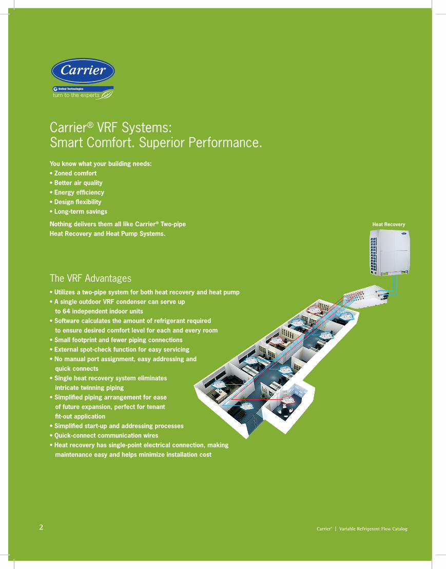
The VRF Advantages• Utilizes a two-pipe system for both heat recovery and heat pump• A single outdoor VRF condenser can serve up
to 64 independent indoor units• Software calculates the amount of refrigerant required
to ensure desired comfort level for each and every room• Small footprint and fewer piping connections• External spot-check function for easy servicing• No manual port assignment, easy addressing and
quick connects• Single heat recovery system eliminates
intricate twinning piping• Simplified piping arrangement for ease
of future expansion, perfect for tenant fit-out application
• Simplified start-up and addressing processes• Quick-connect communication wires• Heat recovery has single-point electrical connection, making
maintenance easy and helps minimize installation cost
Carrier® VRF Systems: Smart Comfort. Superior Performance. You know what your building needs: • Zoned comfort• Better air quality• Energy efficiency• Design flexibility• Long-term savings
Nothing delivers them all like Carrier® Two-pipe Heat Recovery and Heat Pump Systems.
Heat Recovery

Carrier® | Variable Refrigerant Flow 3
Revolutionary Design
Small Footprint VRF systems provide several installation advantages by eliminating the need to install large distribution fans, water pumps and large pipes. VRF systems do not require dedicated maintenance rooms or service shafts, freeing up valuable real estate space in the buildings. The Carrier® VRF Heat Recovery requires less space because of it's non-modular design. For example, the heat recovery 20-ton system is 40% smaller compared to other VRF outdoor units in the marketplace.
High EfficiencyCarrier® VRF achieves high efficiency in cooling and heating by utilizing all DC Inverter compressors and all DC fan motors and high-efficiency heat exchangers. The cooling IEER is 24.6 and heating SCHE is up to 30.0.
High Heating PerformanceThe system provides heating down to -13° F with up to 60% of the rated heating capacity. This is just one more way Carrier® delivers comfort solutions for any indoor space anytime of the year.
Enhanced Defrost ControlThe enhanced defrost control adjusts the defrosting cycle time and frequency based on system operating environments. Using intelligent defrosting, Carrier® VRF system are able to achieve heating capacity quicker than typical defrosting methods. In addition, the bottom sections of the outdoor unit coils are specially circuited for defrost operation—eliminating the need for base-pan heaters.
Hea
ting
Cap
acity
INTELLIGENT DEFROSTING TYPICAL DEFROSTING
Time
6 8 10 12 14 16 18 20 20L 22 24 26 28
100
80
60
40
20
0
HIGH HEATING PERFORMANCE(Average of up to 60% at 5° F)
Tons
35
30
25
20
15
10
5
0 6 8 10 12 14 16 18 20 22 24 26 28
SCHE (Simultaneous Cooling Heating Efficiency) IEER (Integrated Energy Efficiency Ratio)
HIGH EFFICIENCY
Tons
20 ton unit is
5' smaller than the competition
5 feet
Perc
enta
ge
4 Carrier® | Variable Refrigerant Flow
Advanced Technology
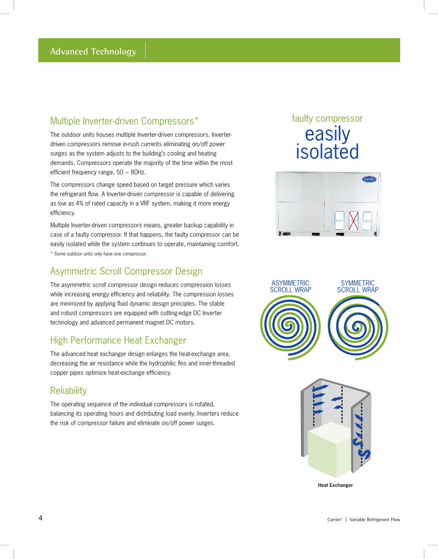
Multiple Inverter-driven Compressors* The outdoor units houses multiple Inverter-driven compressors. Inverter-driven compressors remove in-rush currents eliminating on/off power surges as the system adjusts to the building’s cooling and heating demands. Compressors operate the majority of the time within the most efficient frequency range, 50 ~ 80Hz.
The compressors change speed based on target pressure which varies the refrigerant flow. A Inverter-driven compressor is capable of delivering as low as 4% of rated capacity in a VRF system, making it more energy efficiency.
Multiple Inverter-driven compressors means, greater backup capability in case of a faulty compressor. If that happens, the faulty compressor can be easily isolated while the system continues to operate, maintaining comfort. * Some outdoor units only have one compressor.
Asymmetric Scroll Compressor DesignThe asymmetric scroll compressor design reduces compression losses while increasing energy efficiency and reliability. The compression losses are minimized by applying fluid dynamic design principles. The stable and robust compressors are equipped with cutting-edge DC Inverter technology and advanced permanent magnet DC motors.
High Performance Heat Exchanger The advanced heat exchanger design enlarges the heat-exchange area, decreasing the air resistance while the hydrophilic fins and inner-threaded copper pipes optimize heat-exchange efficiency.
ReliabilityThe operating sequence of the individual compressors is rotated, balancing its operating hours and distributing load evenly. Inverters reduce the risk of compressor failure and eliminate on/off power surges.
faulty compressor
easily isolated
ASYMMETRIC SCROLL WRAP
SYMMETRIC SCROLL WRAP
Heat Exchanger
Carrier® | Variable Refrigerant Flow 5
Advanced Technology
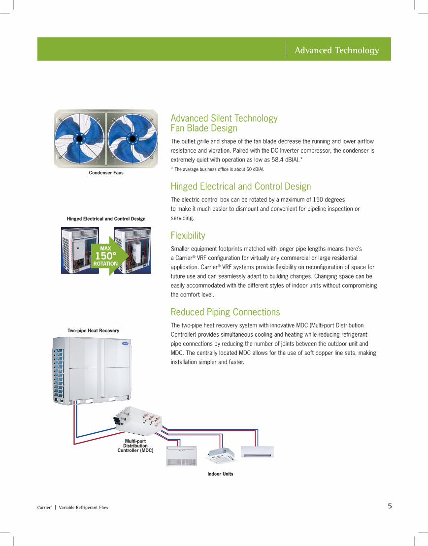
Advanced Silent Technology Fan Blade Design The outlet grille and shape of the fan blade decrease the running and lower airflow resistance and vibration. Paired with the DC Inverter compressor, the condenser is extremely quiet with operation as low as 58.4 dB(A).* * The average business office is about 60 dB(A).
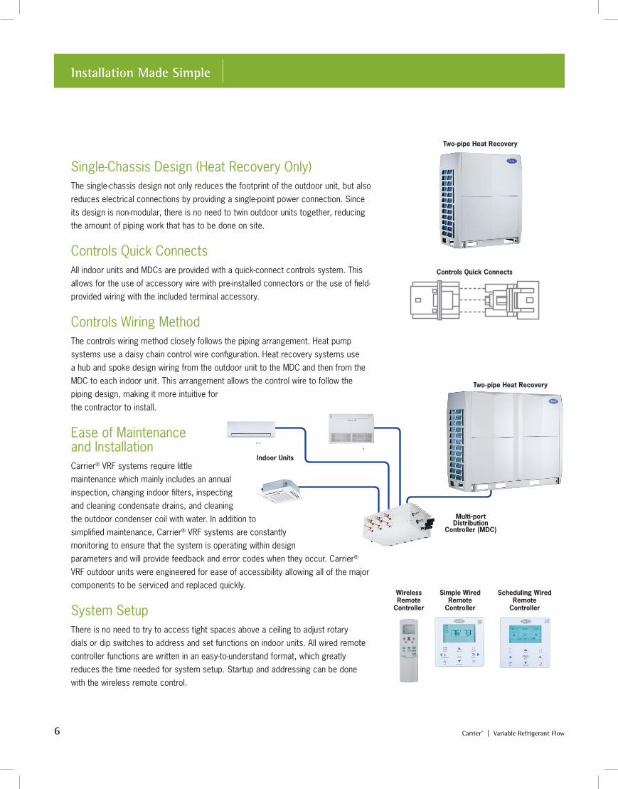
Hinged Electrical and Control Design The electric control box can be rotated by a maximum of 150 degrees to make it much easier to dismount and convenient for pipeline inspection or servicing.
Flexibility Smaller equipment footprints matched with longer pipe lengths means there’s a Carrier® VRF configuration for virtually any commercial or large residential application. Carrier® VRF systems provide flexibility on reconfiguration of space for future use and can seamlessly adapt to building changes. Changing space can be easily accommodated with the different styles of indoor units without compromising the comfort level.
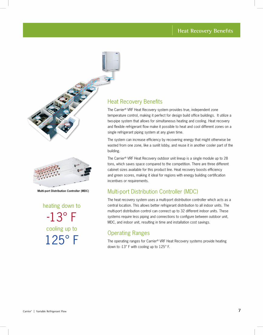
Reduced Piping Connections The two-pipe heat recovery system with innovative MDC (Multi-port Distribution Controller) provides simultaneous cooling and heating while reducing refrigerant pipe connections by reducing the number of joints between the outdoor unit and MDC. The centrally located MDC allows for the use of soft copper line sets, making installation simpler and faster.
Max. 150o Max. 150o
MAX
150°ROTATION
Condenser Fans
Two-pipe Heat Recovery
Multi-port Distribution
Controller (MDC)
Indoor Units
Hinged Electrical and Control Design
6 Carrier® | Variable Refrigerant Flow
Installation Made Simple
Single-Chassis Design (Heat Recovery Only)The single-chassis design not only reduces the footprint of the outdoor unit, but also reduces electrical connections by providing a single-point power connection. Since its design is non-modular, there is no need to twin outdoor units together, reducing the amount of piping work that has to be done on site.
Controls Quick Connects All indoor units and MDCs are provided with a quick-connect controls system. This allows for the use of accessory wire with pre-installed connectors or the use of field-provided wiring with the included terminal accessory.
Controls Wiring Method The controls wiring method closely follows the piping arrangement. Heat pump systems use a daisy chain control wire configuration. Heat recovery systems use a hub and spoke design wiring from the outdoor unit to the MDC and then from the MDC to each indoor unit. This arrangement allows the control wire to follow the piping design, making it more intuitive for the contractor to install.
Ease of Maintenance and Installation Carrier® VRF systems require little maintenance which mainly includes an annual inspection, changing indoor filters, inspecting and cleaning condensate drains, and cleaning the outdoor condenser coil with water. In addition to simplified maintenance, Carrier® VRF systems are constantly monitoring to ensure that the system is operating within design parameters and will provide feedback and error codes when they occur. Carrier® VRF outdoor units were engineered for ease of accessibility allowing all of the major components to be serviced and replaced quickly.
System SetupThere is no need to try to access tight spaces above a ceiling to adjust rotary dials or dip switches to address and set functions on indoor units. All wired remote controller functions are written in an easy-to-understand format, which greatly reduces the time needed for system setup. Startup and addressing can be done with the wireless remote control.
Two-pipe Heat Recovery
Multi-port Distribution
Controller (MDC)
Indoor Units
Two-pipe Heat Recovery
Controls Quick Connects
Wireless Remote
Controller
Simple Wired Remote
Controller
Scheduling Wired Remote
Controller
Carrier® | Variable Refrigerant Flow 7
Heat Recovery Benefits
Heat Recovery Benefits The Carrier® VRF Heat Recovery system provides true, independent zone temperature control, making it perfect for design build office buildings. It utilize a two-pipe system that allows for simultaneous heating and cooling. Heat recovery and flexible refrigerant flow make it possible to heat and cool different zones on a single refrigerant piping system at any given time.
The system can increase efficiency by recovering energy that might otherwise be wasted from one zone, like a sunlit lobby, and reuse it in another cooler part of the building.
The Carrier® VRF Heat Recovery outdoor unit lineup is a single module up to 28 tons, which saves space compared to the competition. There are three different cabinet sizes available for this product line. Heat recovery boosts efficiency and green scores, making it ideal for regions with energy building certification incentives or requirements.
Multi-port Distribution Controller (MDC) The heat recovery system uses a multi-port distribution controller which acts as a central location. This allows better refrigerant distribution to all indoor units. The multi-port distribution control can connect up to 32 different indoor units. These systems require less piping and connections to configure between outdoor unit, MDC, and indoor unit, resulting in time and installation cost savings.
Operating Ranges The operating ranges for Carrier® VRF Heat Recovery systems provide heating down to -13° F with cooling up to 125° F.
heating down to
-13° Fcooling up to
125° F
Multi-port Distribution Controller (MDC)
8 Carrier® | Variable Refrigerant Flow
Heat Recovery Benefits
Heating Refrigerant Temperature ResetThe heating refrigerant temperature reset allows the user to set the schedule based on outdoor temperature and the maximum capacity that the outdoor unit will deliver. This means when it’s warmer, ambient temperatures you can save energy and colder temperatures you can get the heat you need for the building. This results in optimized energy and building performance throughout the entire heating season.
Heating Flexibility with Up-size Many areas of the country need extreme heating performance in low ambient conditions. Carrier® VRF Heat Recovery gives you the best of both worlds by providing heating when you need it. To achieve this, simply upsize the outdoor unit only to improve the heating performance of the entire system in low ambient operation.
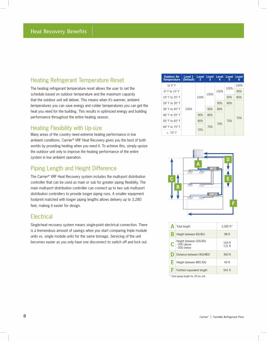
Piping Length and Height DifferenceThe Carrier® VRF Heat Recovery system includes the multi-port distribution controller that can be used as main or sub for greater piping flexibility. The main multi-port distribution controller can connect up to two sub multi-port distribution controllers to provide longer piping runs. A smaller equipment footprint matched with longer piping lengths allows delivery up to 3,280
feet, making it easier for design.
ElectricalSingle-heat recovery system means single-point electrical connection. There is a tremendous amount of savings when you start comparing triple module units vs. single module units for the same tonnage. Servicing of the unit becomes easier as you only have one disconnect to switch off and lock out.
A Total length 3,280 ft*
B Height between IDU-IDU 98 ft
CHeight between ODU-IDU- ODU above- ODU below
164 ft131 ft
D Distance between ODU-MDC 360 ft
E Height between MDC-IDU 49 ft
F Farthest equivalent length 541 ft
* Total piping length for 28 ton unit
F
E
B
C
DA
MCD
SMCD
Outdoor Air Temperature
Level 1 (Default)
Level 2
Level 3
Level 4
Level 5
Level 6
to 5° F
100%
100%100%
100%100%
100%
6° F to 15° F 90%
16° F to 25° F 90% 80%
26° F to 35° F 90% 80%
70%
36° F to 45° F 90% 80%
70%
46° F to 55° F 90% 80%
70%56° F to 65° F 80%
70%66° F to 75° F70%
> 75° F

Carrier® | Variable Refrigerant Flow 9
Heat Pump Benefits
3-phase Heat Pump Carrier® VRF Heat Pumps boast variable speed technology with multiple inverter compressors. This significantly improves system efficiency and reliability. Carrier® VRF heat pump capacity ranges from 6 tons up to 36 tons in a modular design, available as single, double or triple module. Heat pump systems are great for applications that do not require heating and cooling at the same time, such as a big auditorium.
Operating Ranges The operating ranges for Carrier® VRF Heat Pump systems provide heating down to -5° with cooling up to 125° F.
Piping Length and Height DifferenceCarrier® VRF Heat Pumps can deliver piping lengths of up to 3,280 feet. This leads to fewer limitations, making it much easier to design for floors with many small rooms, or for tenants who often rearrange floor layouts. Y-shaped branching joints on the refrigerant pipes between outdoor units ensure that refrigerant flow is equalized to each branch for enhanced system reliability.
Single-phase VRF Heat Pump The Carrier® Single-phase VRF Heat Pump is an excellent solution for spaces too small for 3-phase VRF, yet too large for residential ductless. It delivers the efficiency, flexibility and control of VRF, but in a smaller capacity package and has a lower power requirement.
Single-phase Heat Pump Applications Single-phase VRF Heat Pump systems offer design flexibility when a building needs to be divided into smaller units or expand usable space in size. This system is a perfect choice for applications like one to two story office buildings, strip malls and retail spaces, fire and police stations, and banks, to name just a few.
Single-phase VRF Heat Pump systems can also be easily integrated into any home, no matter the demands of the space. The system allows for a long line length between the outdoor and indoor units, offering more options for installation between floors of your home. It utilizes the centralized controls network with an expanded line of ten indoor unit styles.
heating down to
-5° Fcooling up to
125° F
A Total length 3,280 ft
B Height between IDU-IDU 98 ft
C Farthest pipe from 1st branch 295 ft
DHeight between ODU-IDU- ODU above- ODU below
164 ft131 ft
E Farthest equivalent length 738 ft
E
D
C
B
A
Note: Not applicable to Single-phase.
Section Title
10 Carrier® | Variable Refrigerant Flow Catalog
Carrier® VRF Systems: Outdoor Units
Outdoor U
nits
11Carrier® | Variable Refrigerant Flow
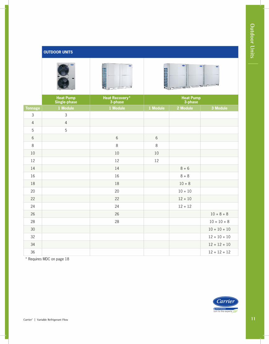
OUTDOOR UNITS
Heat Pump Single-phase
Heat Recovery* 3-phase
Heat Pump 3-phase
Tonnage 1 Module 1 Module 1 Module 2 Module 3 Module
3 3
4 4
5 5
6 6 6
8 8 8
10 10 10
12 12 12
14 14 8 + 6
16 16 8 + 8
18 18 10 + 8
20 20 10 + 10
22 22 12 + 10
24 24 12 + 12
26 26 10 + 8 + 8
28 28 10 + 10 + 8
30 10 + 10 + 10
32 12 + 10 + 10
34 12 + 12 + 10
36 12 + 12 + 12
* Requires MDC on page 18
12 Carrier® | Variable Refrigerant Flow
Outdoor U
nits: Heat Recovery Technical Specs
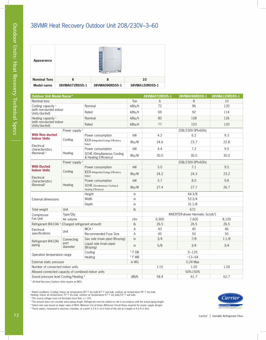
38VMR Heat Recovery Outdoor Unit 208/230V–3–60
Technical Specifications
Outdoor Unit Model Name* 38VMA072RDS5-1 38VMA096RDS5-1 38VMA120RDS5-1Nominal tons Ton 6 8 10Cooling capacity 1 (with non-ducted indoor Units/ducted)
Nominal kBtu/h 72 96 120
Rated kBtu/h 69 92 114
Heating capacity 1 (with non-ducted indoor Units/ducted)
Nominal kBtu/h 80 108 126
Rated kBtu/h 77 103 120
With Non-ducted Indoor Units Electrical characteristics (Nominal) 1
Power supply 2 208/230V-3Ph-60Hz
CoolingPower consumption kW 4.2 6.2 9.3IEER (Integrated Energy Efficiency Ratio)
Btu/W 24.6 23.7 22.8
HeatingPower consumption kW 4.4 7.2 9.5 SCHE (Simultaneous Cooling & Heating Efficiency) Btu/W 30.0 30.0 30.0
With Ducted Indoor Units Electrical characteristics (Nominal)1
Power supply 2 208/230V-3Ph-60Hz
CoolingPower consumption kW 5.0 7.1 9.5 IEER (Integrated Energy Efficiency Ratio)
Btu/W 24.2 24.3 23.2
HeatingPower consumption kW 5.7 8.0 9.8 SCHE (Simultaneous Cooling & Heating Efficiency)
Btu/W 27.4 27.7 26.7
External dimensions
Height in 64-3/8Width in 52-3/4
Depth in 31-1/8
Total weight Unit lb 672
CompressorFan Unit
Type/Qty INVERTER-driven Hermetic Scroll/1Air volume cfm 6,900 7,600 8,100
Refrigerant (R410A) 3 (Charged refrigerant amount) lb 26.5 26.5 26.5
Electrical specifications Unit
MCA 4 A 43 45 46Recommended Fuse Size A 45 50 50
Refrigerant (R410A) piping
Connecting port diameter
Gas side (main pipe) (Brazing) in 3/4 7/8 1-1/8Liquid side (main pipe)(Brazing) in 5/8 3/4 3/4
Operation temperature rangeCooling ° F DB 5~125Heating ° F WB –13~64
External static pressure in WG 0.24 MaxNumber of connected indoor units 1-15 1-20 1-24Allowed connected capacity of combined indoor units 50%-150%Sound pressure level Cooling/Heating 5 dB(A) 58.4 61.7 62.7
Appearance
Nominal Tons 6 8 10
Model name 38VMA072RDS5-1 38VMA096RDS5-1 38VMA120RDS5-1
1 Rated conditions: Cooling: Indoor air temperature 80° F dry bulb/67° F wet bulb, outdoor air temperature 95° F dry bulb. Heating: Indoor air temperature 70° F dry bulb, outdoor air temperature 47° F dry bulb/43° F wet bulb. 2 The source voltage must not fluctuate more than +/- 10%.3 The amount does not consider extra piping length. Refrigerant must be added on site in accordance with the actual piping length.4 Select wire size based on larger value of MCA: Minimum Circuit Amps (Minimum Circuit Amps required for power supply design).5 These values, measured in anechoic chamber, at a point 3.3 ft (1 m) in front of the unit at a height of 4.6 ft (1.4m).
* All Heat Recovery Outdoor Units require an MDC.
13Carrier® | Variable Refrigerant Flow
Appearance
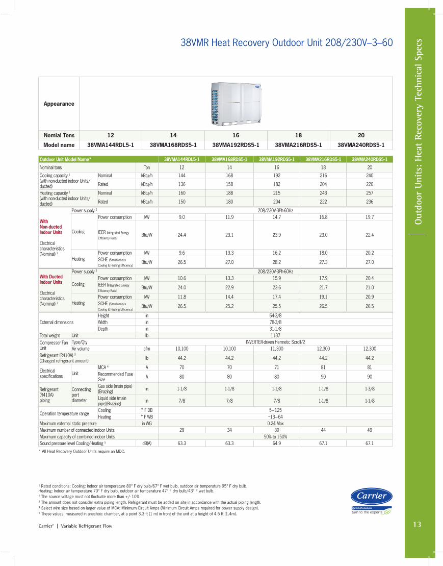
Nomial Tons 12 14 16 18 20
Model name 38VMA144RDL5-1 38VMA168RDS5-1 38VMA192RDS5-1 38VMA216RDS5-1 38VMA240RDS5-1
O
utdo
or U
nits
: H
eat
Reco
very
Tec
hnic
al S
pecs38VMR Heat Recovery Outdoor Unit 208/230V–3–60
1 Rated conditions: Cooling: Indoor air temperature 80° F dry bulb/67° F wet bulb, outdoor air temperature 95° F dry bulb. Heating: Indoor air temperature 70° F dry bulb, outdoor air temperature 47° F dry bulb/43° F wet bulb. 2 The source voltage must not fluctuate more than +/- 10%.3 The amount does not consider extra piping length. Refrigerant must be added on site in accordance with the actual piping length.4 Select wire size based on larger value of MCA: Minimum Circuit Amps (Minimum Circuit Amps required for power supply design).5 These values, measured in anechoic chamber, at a point 3.3 ft (1 m) in front of the unit at a height of 4.6 ft (1.4m).
Outdoor Unit Model Name* 38VMA144RDL5-1 38VMA168RDS5-1 38VMA192RDS5-1 38VMA216RDS5-1 38VMA240RDS5-1
Nominal tons Ton 12 14 16 18 20
Cooling capacity 1 (with non-ducted indoor Units/ducted)
Nominal kBtu/h 144 168 192 216 240
Rated kBtu/h 136 158 182 204 220
Heating capacity 1 (with non-ducted indoor Units/ducted)
Nominal kBtu/h 160 188 215 243 257
Rated kBtu/h 150 180 204 222 236
With Non-ducted Indoor Units Electrical characteristics (Nominal) 1
Power supply 2 208/230V-3Ph-60Hz
Cooling
Power consumption kW 9.0 11.9 14.7 16.8 19.7
IEER (Integrated Energy
Efficiency Ratio)Btu/W 24.4 23.1 23.9 23.0 22.4
HeatingPower consumption kW 9.6 13.3 16.2 18.0 20.2 SCHE (Simultaneous
Cooling & Heating Efficiency)Btu/W 26.5 27.0 28.2 27.3 27.0
With Ducted Indoor Units Electrical characteristics (Nominal) 1
Power supply 2 208/230V-3Ph-60Hz
CoolingPower consumption kW 10.6 13.3 15.9 17.9 20.4 IEER (Integrated Energy
Efficiency Ratio)Btu/W 24.0 22.9 23.6 21.7 21.0
HeatingPower consumption kW 11.8 14.4 17.4 19.1 20.9 SCHE (Simultaneous
Cooling & Heating Efficiency)Btu/W 26.5 25.2 25.5 26.5 26.5
External dimensionsHeight in 64-3/8Width in 78-3/8Depth in 31-1/8
Total weight Unit lb 1137Compressor Fan Unit
Type/Qty INVERTER-driven Hermetic Scroll/2Air volume cfm 10,100 10,100 11,300 12,300 12,300
Refrigerant (R410A) 3 (Charged refrigerant amount) lb 44.2 44.2 44.2 44.2 44.2
Electrical specifications Unit
MCA 4 A 70 70 71 81 81Recommended Fuse Size A 80 80 80 90 90
Refrigerant (R410A) piping
Connecting port diameter
Gas side (main pipe) (Brazing) in 1-1/8 1-1/8 1-1/8 1-1/8 1-3/8
Liquid side (main pipe)(Brazing) in 7/8 7/8 7/8 1-1/8 1-1/8
Operation temperature rangeCooling ° F DB 5~125Heating ° F WB –13~64
Maximum external static pressure in WG 0.24 MaxMaximum number of connected indoor Units 29 34 39 44 49Maximum capacity of combined indoor Units 50% to 150%Sound pressure level Cooling/Heating 5 dB(A) 63.3 63.3 64.9 67.1 67.1
* All Heat Recovery Outdoor Units require an MDC.

14 Carrier® | Variable Refrigerant Flow
Outdoor U
nits: Heat Recovery Technical Specs
Appearance
Nomial Tons 20 22 24 26 28
Model name 38VMA240RDL5-1 38VMA264RDS5-1 38VMA288RDS5-1 38VMA312RDS5-1 38VMA336RDS5-1
38VMR Heat Recovery Outdoor Unit 208/230V–3-60
1 Rated conditions: Cooling: Indoor air temperature 80° F dry bulb/67° F wet bulb, outdoor air temperature 95° F dry bulb. Heating: Indoor air temperature 70° F dry bulb, outdoor air temperature 47° F dry bulb/43° F wet bulb. 2 The source voltage must not fluctuate more than +/- 10%.3 The amount does not consider extra piping length. Refrigerant must be added on site in accordance with the actual piping length.4 Select wire size based on larger value of MCA: Minimum Circuit Amps (Minimum Circuit Amps required for power supply design).5 These values, measured in anechoic chamber, at a point 3.3 ft (1 m) in front of the unit at a height of 4.6 ft (1.4m).
Outdoor Unit Model Name* 38VMA240RDL5-1 38VMA264RDS5-1 38VMA288RDS5-1 38VMA312RDS5-1 38VMA336RDS5-1Nominal tons Ton 20 22 24 26 28Cooling capacity 1 (with non-ducted indoor Units/ducted)
Nominal kBtu/h 240 264 288 312 336
Rated kBtu/h 228 248 274 296 308
Heating capacity 1 (with non-ducted indoor Units/ducted)
Nominal kBtu/h 270 295 323 343 357
Rated kBtu/h 256 282 298 314 322
With Non-ducted Indoor Units Electrical characteristics (Nominal) 1
Power supply 2 208/230V-3Ph-60Hz
CoolingPower consumption kW 20.4 23.2 26.4 31.8 33.1IEER (Integrated Energy
Efficiency Ratio)Btu/W 22.4 22.0 21.0 20.2 19.5
HeatingPower consumption kW 20.2 23.5 25.8 28.9 29.6 SCHE (Simultaneous
Cooling & Heating Efficiency)Btu/W 30.0 29.6 29.3 28.5 28.0
With Ducted Indoor Units Electrical characteristics (Nominal) 1
Power supply 2 208/230V-3Ph-60Hz
CoolingPower consumption kW 20.7 23.2 28.0 31.2 33.1 IEER (Integrated Energy
Efficiency Ratio)Btu/W 21.1 21.0 20.5 19.8 19.0
HeatingPower consumption kW 21.0 23.7 25.5 27.4 29.2 SCHE (Simultaneous
Cooling & Heating Efficiency)Btu/W 28.0 27.5 27.0 26.5 25.5
External dimensionsHeight in 64-3/8Width in 105-7/8Depth in 31-1/8
Total weight Unit lb 1627
Compressor Fan Unit
Type/Qty INVERTER-driven Hermitc Scroll/3Air volume cfm 14,500 15,500 15,500 16,500 16,500
Refrigerant (R410A) 3 (Charged refrigerant amount) lb 77.2 77.2 77.2 77.2 77.2
Electrical specifications Unit
MCA 4 A 101 104 104 106 106Recommended Fuse Size A 110 110 110 110 110
Refrigerant (R410A) piping
Connecting port diameter
Gas side (main pipe) (Brazing) in 1-3/8 1-3/8 1-3/8 1-5/8 1-5/8
Liquid side (main pipe)(Brazing) in 1-1/8 1-1/8 1-1/8 1-1/8 1-1/8
Operation temperature rangeCooling ° F DB 5~125Heating ° F WB –13~64
Maximum external static pressure in WG 0.24 MaxMaximum number of connected indoor Units 49 54 59 64 64Maximum capacity of combined indoor Units 50% to 150%Sound pressure level Cooling/Heating 5 dB(A) 63.9 64.8 64.8 66.4 67.2
* All Heat Recovery Outdoor Units require an MDC.
15Carrier® | Variable Refrigerant Flow
O
utdo
or U
nits
: H
eat
Reco
very
Tec
hnic
al S
pecs
Technical Specifications
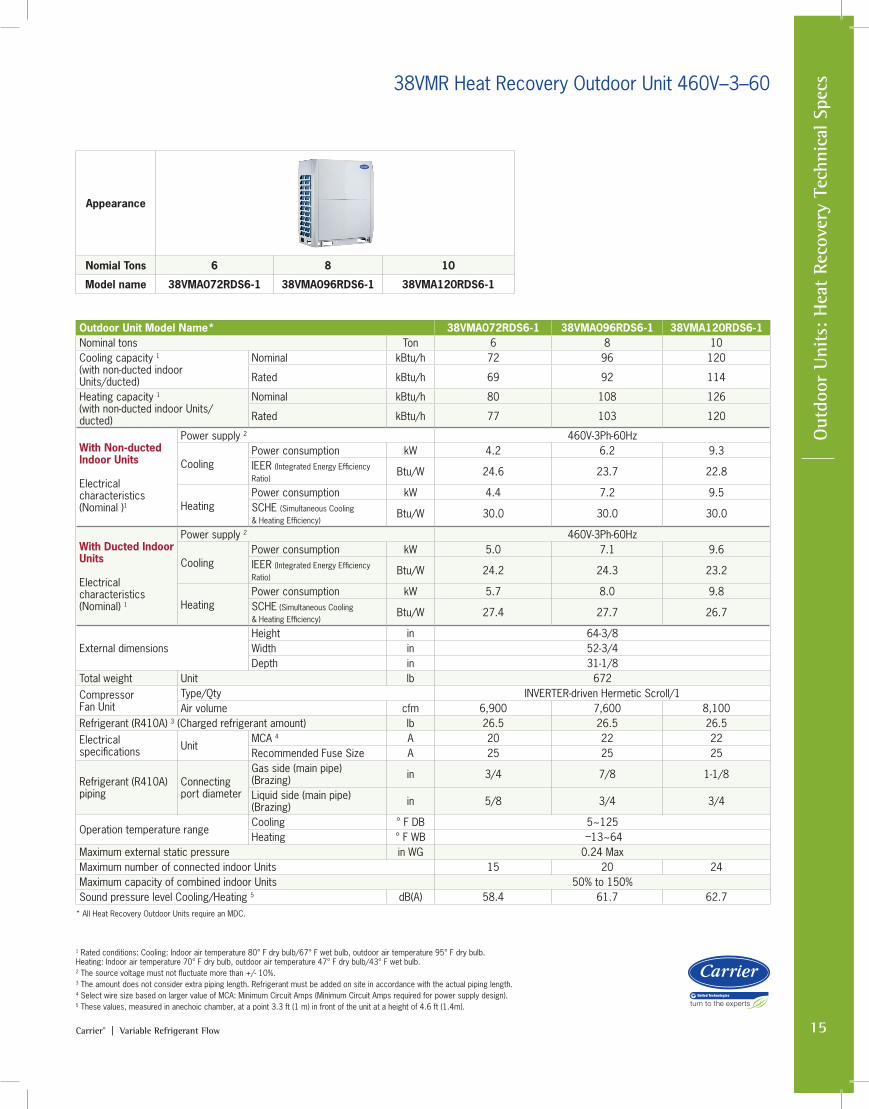
38VMR Heat Recovery Outdoor Unit 460V–3–60
Appearance
Nomial Tons 6 8 10
Model name 38VMA072RDS6-1 38VMA096RDS6-1 38VMA120RDS6-1
1 Rated conditions: Cooling: Indoor air temperature 80° F dry bulb/67° F wet bulb, outdoor air temperature 95° F dry bulb. Heating: Indoor air temperature 70° F dry bulb, outdoor air temperature 47° F dry bulb/43° F wet bulb. 2 The source voltage must not fluctuate more than +/- 10%.3 The amount does not consider extra piping length. Refrigerant must be added on site in accordance with the actual piping length.4 Select wire size based on larger value of MCA: Minimum Circuit Amps (Minimum Circuit Amps required for power supply design).5 These values, measured in anechoic chamber, at a point 3.3 ft (1 m) in front of the unit at a height of 4.6 ft (1.4m).
Outdoor Unit Model Name* 38VMA072RDS6-1 38VMA096RDS6-1 38VMA120RDS6-1Nominal tons Ton 6 8 10Cooling capacity 1 (with non-ducted indoor Units/ducted)
Nominal kBtu/h 72 96 120
Rated kBtu/h 69 92 114
Heating capacity 1 (with non-ducted indoor Units/ducted)
Nominal kBtu/h 80 108 126
Rated kBtu/h 77 103 120
With Non-ducted Indoor Units Electrical characteristics (Nominal )1
Power supply 2 460V-3Ph-60Hz
CoolingPower consumption kW 4.2 6.2 9.3IEER (Integrated Energy Efficiency Ratio)
Btu/W 24.6 23.7 22.8
HeatingPower consumption kW 4.4 7.2 9.5 SCHE (Simultaneous Cooling & Heating Efficiency)
Btu/W 30.0 30.0 30.0
With Ducted Indoor Units Electrical characteristics (Nominal) 1
Power supply 2 460V-3Ph-60Hz
CoolingPower consumption kW 5.0 7.1 9.6 IEER (Integrated Energy Efficiency Ratio)
Btu/W 24.2 24.3 23.2
HeatingPower consumption kW 5.7 8.0 9.8SCHE (Simultaneous Cooling & Heating Efficiency)
Btu/W 27.4 27.7 26.7
External dimensionsHeight in 64-3/8Width in 52-3/4Depth in 31-1/8
Total weight Unit lb 672CompressorFan Unit
Type/Qty INVERTER-driven Hermetic Scroll/1Air volume cfm 6,900 7,600 8,100
Refrigerant (R410A) 3 (Charged refrigerant amount) lb 26.5 26.5 26.5Electrical specifications Unit
MCA 4 A 20 22 22Recommended Fuse Size A 25 25 25
Refrigerant (R410A) piping
Connecting port diameter
Gas side (main pipe) (Brazing) in 3/4 7/8 1-1/8
Liquid side (main pipe)(Brazing) in 5/8 3/4 3/4
Operation temperature rangeCooling ° F DB 5~125Heating ° F WB –13~64
Maximum external static pressure in WG 0.24 MaxMaximum number of connected indoor Units 15 20 24Maximum capacity of combined indoor Units 50% to 150%Sound pressure level Cooling/Heating 5 dB(A) 58.4 61.7 62.7
* All Heat Recovery Outdoor Units require an MDC.
16 Carrier® | Variable Refrigerant Flow
Outdoor U
nits: Heat Recovery Technical Specs
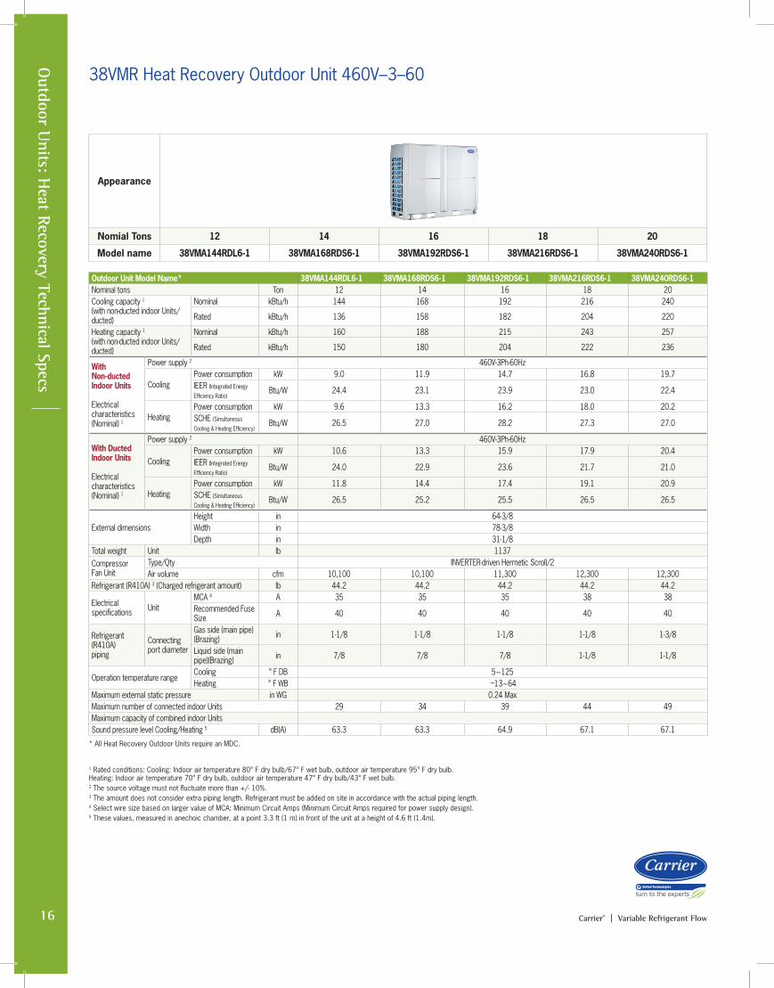
38VMR Heat Recovery Outdoor Unit 460V–3–60
Appearance
Nomial Tons 12 14 16 18 20
Model name 38VMA144RDL6-1 38VMA168RDS6-1 38VMA192RDS6-1 38VMA216RDS6-1 38VMA240RDS6-1
1 Rated conditions: Cooling: Indoor air temperature 80° F dry bulb/67° F wet bulb, outdoor air temperature 95° F dry bulb. Heating: Indoor air temperature 70° F dry bulb, outdoor air temperature 47° F dry bulb/43° F wet bulb. 2 The source voltage must not fluctuate more than +/- 10%.3 The amount does not consider extra piping length. Refrigerant must be added on site in accordance with the actual piping length.4 Select wire size based on larger value of MCA: Minimum Circuit Amps (Minimum Circuit Amps required for power supply design).5 These values, measured in anechoic chamber, at a point 3.3 ft (1 m) in front of the unit at a height of 4.6 ft (1.4m).
Outdoor Unit Model Name* 38VMA144RDL6-1 38VMA168RDS6-1 38VMA192RDS6-1 38VMA216RDS6-1 38VMA240RDS6-1Nominal tons Ton 12 14 16 18 20Cooling capacity 1 (with non-ducted indoor Units/ducted)
Nominal kBtu/h 144 168 192 216 240
Rated kBtu/h 136 158 182 204 220
Heating capacity 1 (with non-ducted indoor Units/ducted)
Nominal kBtu/h 160 188 215 243 257
Rated kBtu/h 150 180 204 222 236
With Non-ducted Indoor Units Electrical characteristics (Nominal) 1
Power supply 2 460V-3Ph-60Hz
CoolingPower consumption kW 9.0 11.9 14.7 16.8 19.7IEER (Integrated Energy
Efficiency Ratio)Btu/W 24.4 23.1 23.9 23.0 22.4
HeatingPower consumption kW 9.6 13.3 16.2 18.0 20.2 SCHE (Simultaneous
Cooling & Heating Efficiency)Btu/W 26.5 27.0 28.2 27.3 27.0
With Ducted Indoor Units Electrical characteristics (Nominal) 1
Power supply 2 460V-3Ph-60Hz
CoolingPower consumption kW 10.6 13.3 15.9 17.9 20.4 IEER (Integrated Energy
Efficiency Ratio)Btu/W 24.0 22.9 23.6 21.7 21.0
HeatingPower consumption kW 11.8 14.4 17.4 19.1 20.9SCHE (Simultaneous
Cooling & Heating Efficiency)Btu/W 26.5 25.2 25.5 26.5 26.5
External dimensionsHeight in 64-3/8Width in 78-3/8Depth in 31-1/8
Total weight Unit lb 1137CompressorFan Unit
Type/Qty INVERTER-driven Hermetic Scroll/2Air volume cfm 10,100 10,100 11,300 12,300 12,300
Refrigerant (R410A) 3 (Charged refrigerant amount) lb 44.2 44.2 44.2 44.2 44.2
Electrical specifications Unit
MCA 4 A 35 35 35 38 38Recommended Fuse Size A 40 40 40 40 40
Refrigerant (R410A) piping
Connecting port diameter
Gas side (main pipe) (Brazing) in 1-1/8 1-1/8 1-1/8 1-1/8 1-3/8
Liquid side (main pipe)(Brazing) in 7/8 7/8 7/8 1-1/8 1-1/8
Operation temperature rangeCooling ° F DB 5~125Heating ° F WB –13~64
Maximum external static pressure in WG 0.24 MaxMaximum number of connected indoor Units 29 34 39 44 49Maximum capacity of combined indoor Units Sound pressure level Cooling/Heating 5 dB(A) 63.3 63.3 64.9 67.1 67.1
* All Heat Recovery Outdoor Units require an MDC.
17Carrier® | Variable Refrigerant Flow
O
utdo
or U
nits
: H
eat
Reco
very
Tec
hnic
al S
pecs
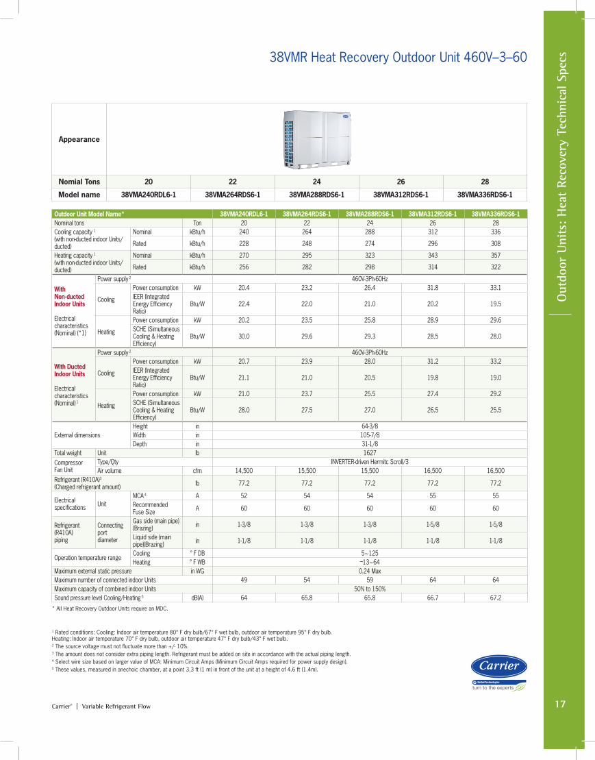
Appearance
Nomial Tons 20 22 24 26 28
Model name 38VMA240RDL6-1 38VMA264RDS6-1 38VMA288RDS6-1 38VMA312RDS6-1 38VMA336RDS6-1
38VMR Heat Recovery Outdoor Unit 460V–3–60
1 Rated conditions: Cooling: Indoor air temperature 80° F dry bulb/67° F wet bulb, outdoor air temperature 95° F dry bulb. Heating: Indoor air temperature 70° F dry bulb, outdoor air temperature 47° F dry bulb/43° F wet bulb. 2 The source voltage must not fluctuate more than +/- 10%.3 The amount does not consider extra piping length. Refrigerant must be added on site in accordance with the actual piping length.4 Select wire size based on larger value of MCA: Minimum Circuit Amps (Minimum Circuit Amps required for power supply design).5 These values, measured in anechoic chamber, at a point 3.3 ft (1 m) in front of the unit at a height of 4.6 ft (1.4m).
Outdoor Unit Model Name* 38VMA240RDL6-1 38VMA264RDS6-1 38VMA288RDS6-1 38VMA312RDS6-1 38VMA336RDS6-1Nominal tons Ton 20 22 24 26 28Cooling capacity 1 (with non-ducted indoor Units/ducted)
Nominal kBtu/h 240 264 288 312 336
Rated kBtu/h 228 248 274 296 308
Heating capacity 1 (with non-ducted indoor Units/ducted)
Nominal kBtu/h 270 295 323 343 357
Rated kBtu/h 256 282 298 314 322
With Non-ducted Indoor Units Electrical characteristics (Nominal) (*1)
Power supply 2 460V-3Ph-60Hz
Cooling
Power consumption kW 20.4 23.2 26.4 31.8 33.1IEER (Integrated Energy Efficiency Ratio)
Btu/W 22.4 22.0 21.0 20.2 19.5
Heating
Power consumption kW 20.2 23.5 25.8 28.9 29.6 SCHE (Simultaneous Cooling & Heating Efficiency)
Btu/W 30.0 29.6 29.3 28.5 28.0
With Ducted Indoor Units Electrical characteristics (Nominal) 1
Power supply 2 460V-3Ph-60Hz
Cooling
Power consumption kW 20.7 23.9 28.0 31.2 33.2 IEER (Integrated Energy Efficiency Ratio)
Btu/W 21.1 21.0 20.5 19.8 19.0
Heating
Power consumption kW 21.0 23.7 25.5 27.4 29.2 SCHE (Simultaneous Cooling & Heating Efficiency)
Btu/W 28.0 27.5 27.0 26.5 25.5
External dimensionsHeight in 64-3/8Width in 105-7/8Depth in 31-1/8
Total weight Unit lb 1627CompressorFan Unit
Type/Qty INVERTER-driven Hermitc Scroll/3Air volume cfm 14,500 15,500 15,500 16,500 16,500
Refrigerant (R410A)3 (Charged refrigerant amount) lb 77.2 77.2 77.2 77.2 77.2
Electrical specifications Unit
MCA 4 A 52 54 54 55 55Recommended Fuse Size A 60 60 60 60 60
Refrigerant (R410A) piping
Connecting port diameter
Gas side (main pipe) (Brazing) in 1-3/8 1-3/8 1-3/8 1-5/8 1-5/8
Liquid side (main pipe)(Brazing) in 1-1/8 1-1/8 1-1/8 1-1/8 1-1/8
Operation temperature rangeCooling ° F DB 5~125Heating ° F WB –13~64
Maximum external static pressure in WG 0.24 MaxMaximum number of connected indoor Units 49 54 59 64 64Maximum capacity of combined indoor Units 50% to 150%Sound pressure level Cooling/Heating 5 dB(A) 64 65.8 65.8 66.7 67.2
* All Heat Recovery Outdoor Units require an MDC.
18 Carrier® | Variable Refrigerant Flow
Multi-port D
istribution Controller Specs
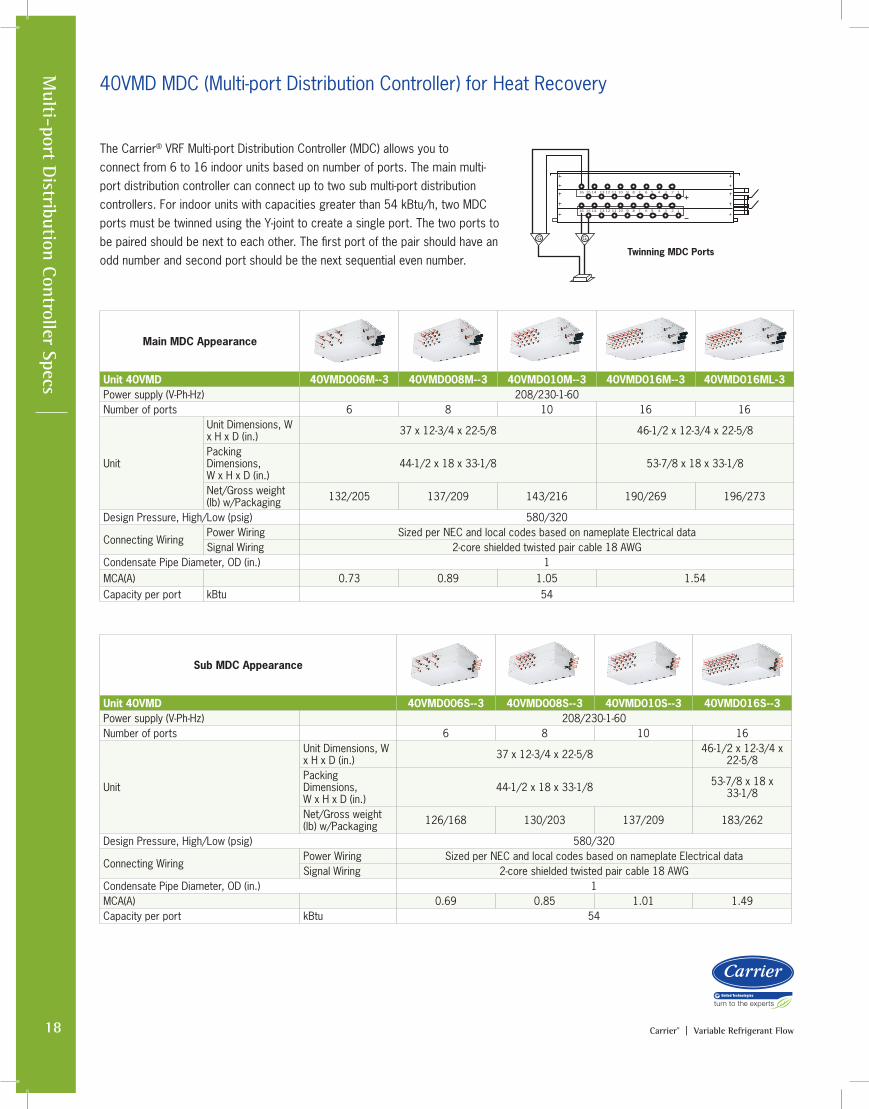
40VMD MDC (Multi-port Distribution Controller) for Heat Recovery
The Carrier® VRF Multi-port Distribution Controller (MDC) allows you to connect from 6 to 16 indoor units based on number of ports. The main multi-port distribution controller can connect up to two sub multi-port distribution controllers. For indoor units with capacities greater than 54 kBtu/h, two MDC ports must be twinned using the Y-joint to create a single port. The two ports to be paired should be next to each other. The first port of the pair should have an odd number and second port should be the next sequential even number.
Main MDC Appearance
Unit 40VMD 40VMD006M--3 40VMD008M--3 40VMD010M--3 40VMD016M--3 40VMD016ML-3Power supply (V-Ph-Hz) 208/230-1-60Number of ports 6 8 10 16 16
Unit
Unit Dimensions, W x H x D (in.) 37 x 12-3/4 x 22-5/8 46-1/2 x 12-3/4 x 22-5/8
Packing Dimensions, W x H x D (in.)
44-1/2 x 18 x 33-1/8 53-7/8 x 18 x 33-1/8
Net/Gross weight (lb) w/Packaging 132/205 137/209 143/216 190/269 196/273
Design Pressure, High/Low (psig) 580/320
Connecting WiringPower Wiring Sized per NEC and local codes based on nameplate Electrical dataSignal Wiring 2-core shielded twisted pair cable 18 AWG
Condensate Pipe Diameter, OD (in.) 1MCA(A) 0.73 0.89 1.05 1.54Capacity per port kBtu 54
Sub MDC Appearance
Unit 40VMD 40VMD006S--3 40VMD008S--3 40VMD010S--3 40VMD016S--3Power supply (V-Ph-Hz) 208/230-1-60Number of ports 6 8 10 16
Unit
Unit Dimensions, W x H x D (in.) 37 x 12-3/4 x 22-5/8 46-1/2 x 12-3/4 x
22-5/8Packing Dimensions, W x H x D (in.)
44-1/2 x 18 x 33-1/8 53-7/8 x 18 x 33-1/8
Net/Gross weight (lb) w/Packaging 126/168 130/203 137/209 183/262
Design Pressure, High/Low (psig) 580/320
Connecting WiringPower Wiring Sized per NEC and local codes based on nameplate Electrical dataSignal Wiring 2-core shielded twisted pair cable 18 AWG
Condensate Pipe Diameter, OD (in.) 1MCA(A) 0.69 0.85 1.01 1.49Capacity per port kBtu 54
Twinning MDC Ports
16 15 14 13 12 11 10 9 8 7 6 5 4 3 2 1
16 15 14 13 12 11 10 9 8 7 6 5 4 3 2 1
GG
19Carrier® | Variable Refrigerant Flow
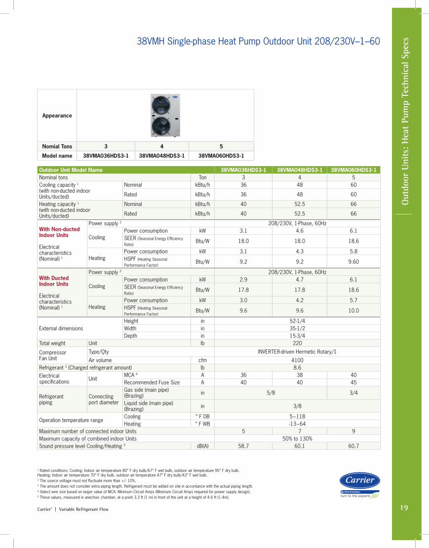
Outdoor Unit Model Name 38VMA036HDS3-1 38VMA048HDS3-1 38VMA060HDS3-1Nominal tons Ton 3 4 5Cooling capacity 1 (with non-ducted indoor Units/ducted)
Nominal kBtu/h 36 48 60
Rated kBtu/h 36 48 60
Heating capacity 1 (with non-ducted indoor Units/ducted)
Nominal kBtu/h 40 52.5 66
Rated kBtu/h 40 52.5 66
With Non-ducted Indoor Units Electrical characteristics (Nominal) 1
Power supply 2 208/230V, 1-Phase, 60Hz
CoolingPower consumption kW 3.1 4.6 6.1 SEER (Seasonal Energy Efficiency Ratio)
Btu/W 18.0 18.0 18.6
HeatingPower consumption kW 3.1 4.3 5.8 HSPF (Heating Seasonal Performance Factor)
Btu/W 9.2 9.2 9.60
With Ducted Indoor Units Electrical characteristics (Nominal) 1
Power supply 2 208/230V, 1-Phase, 60Hz
CoolingPower consumption kW 2.9 4.7 6.1 SEER (Seasonal Energy Efficiency Ratio)
Btu/W 17.8 17.8 18.6
HeatingPower consumption kW 3.0 4.2 5.7 HSPF (Heating Seasonal Performance Factor)
Btu/W 9.6 9.6 10.0
External dimensionsHeight in 52-1/4Width in 35-1/2Depth in 15-3/4
Total weight Unit lb 220
CompressorFan Unit
Type/Qty INVERTER-driven Hermetic Rotary/1
Air volume cfm 4100Refrigerant 3 (Charged refrigerant amount) lb 8.6Electrical specifications Unit
MCA 4 A 36 38 40Recommended Fuse Size A 40 40 45
Refrigerant piping
Connecting port diameter
Gas side (main pipe) (Brazing) in 5/8 3/4
Liquid side (main pipe)(Brazing) in 3/8
Operation temperature rangeCooling ° F DB 5~118Heating ° F WB -13~64
Maximum number of connected indoor Units 5 7 9Maximum capacity of combined indoor Units 50% to 130%Sound pressure level Cooling/Heating 5 dB(A) 58.7 60.1 60.7
1 Rated conditions: Cooling: Indoor air temperature 80° F dry bulb/67° F wet bulb, outdoor air temperature 95° F dry bulb. Heating: Indoor air temperature 70° F dry bulb, outdoor air temperature 47° F dry bulb/43° F wet bulb. 2 The source voltage must not fluctuate more than +/- 10%.3 The amount does not consider extra piping length. Refrigerant must be added on site in accordance with the actual piping length.4 Select wire size based on larger value of MCA: Minimum Circuit Amps (Minimum Circuit Amps required for power supply design).5 These values, measured in anechoic chamber, at a point 3.3 ft (1 m) in front of the unit at a height of 4.6 ft (1.4m).
Out
door
Uni
ts: H
eat
Pum
p Te
chni
cal S
pecs38VMH Single-phase Heat Pump Outdoor Unit 208/230V–1–60
Appearance
Nomial Tons 3 4 5
Model name 38VMA036HDS3-1 38VMA048HDS3-1 38VMA060HDS3-1
20 Carrier® | Variable Refrigerant Flow
Outdoor U
nits: Heat Pum
p Technical Specs
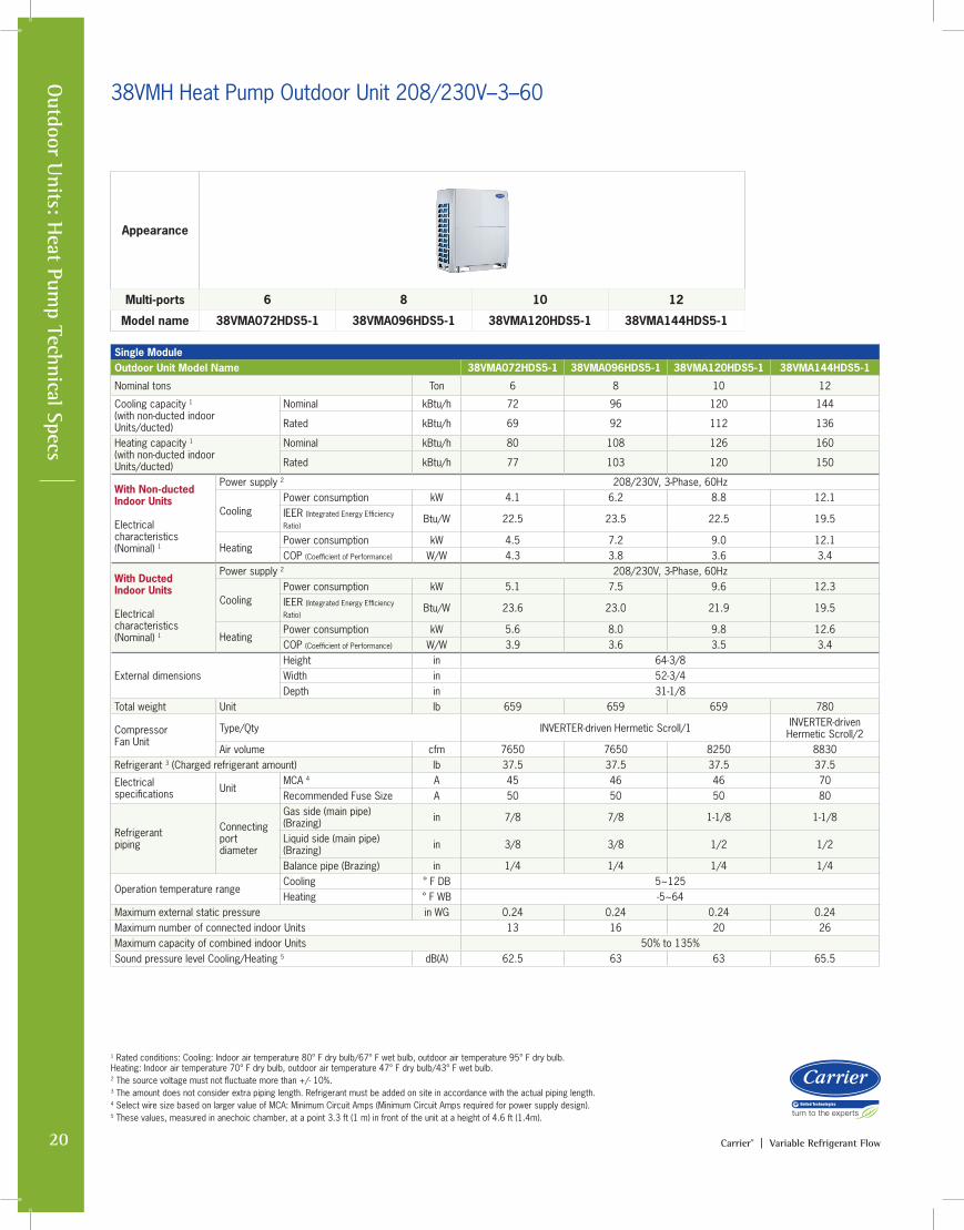
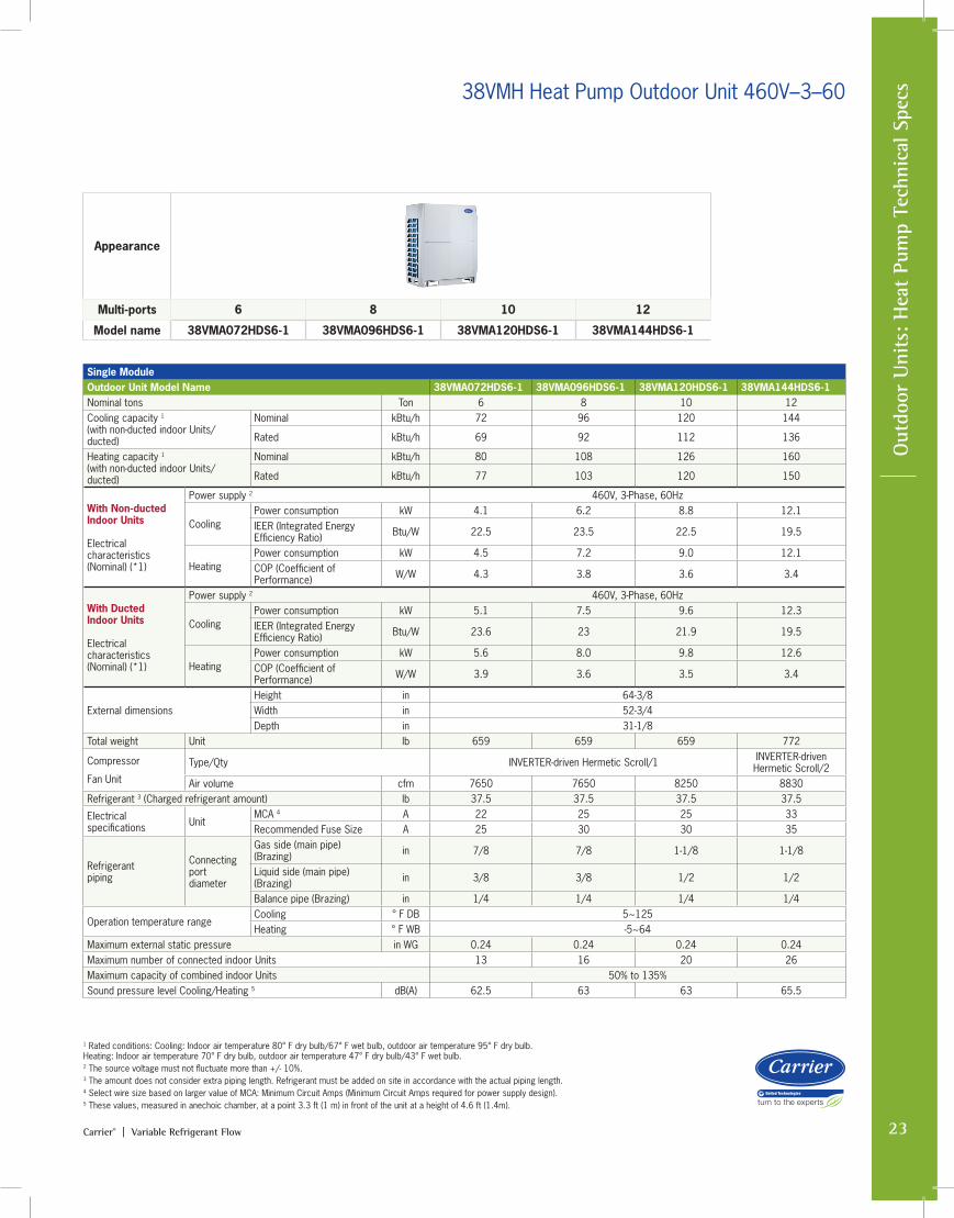
38VMH Heat Pump Outdoor Unit 208/230V–3–60
Appearance
Multi-ports 6 8 10 12
Model name 38VMA072HDS5-1 38VMA096HDS5-1 38VMA120HDS5-1 38VMA144HDS5-1
Single ModuleOutdoor Unit Model Name 38VMA072HDS5-1 38VMA096HDS5-1 38VMA120HDS5-1 38VMA144HDS5-1
Nominal tons Ton 6 8 10 12
Cooling capacity 1 (with non-ducted indoor Units/ducted)
Nominal kBtu/h 72 96 120 144
Rated kBtu/h 69 92 112 136
Heating capacity 1 (with non-ducted indoor Units/ducted)
Nominal kBtu/h 80 108 126 160
Rated kBtu/h 77 103 120 150
With Non-ducted Indoor Units Electrical characteristics (Nominal) 1
Power supply 2 208/230V, 3-Phase, 60Hz
CoolingPower consumption kW 4.1 6.2 8.8 12.1 IEER (Integrated Energy Efficiency
Ratio)Btu/W 22.5 23.5 22.5 19.5
HeatingPower consumption kW 4.5 7.2 9.0 12.1 COP (Coefficient of Performance) W/W 4.3 3.8 3.6 3.4
With Ducted Indoor Units Electrical characteristics (Nominal) 1
Power supply 2 208/230V, 3-Phase, 60Hz
CoolingPower consumption kW 5.1 7.5 9.6 12.3 IEER (Integrated Energy Efficiency
Ratio)Btu/W 23.6 23.0 21.9 19.5
HeatingPower consumption kW 5.6 8.0 9.8 12.6 COP (Coefficient of Performance) W/W 3.9 3.6 3.5 3.4
External dimensionsHeight in 64-3/8Width in 52-3/4Depth in 31-1/8
Total weight Unit lb 659 659 659 780
CompressorFan Unit
Type/Qty INVERTER-driven Hermetic Scroll/1 INVERTER-driven Hermetic Scroll/2
Air volume cfm 7650 7650 8250 8830Refrigerant 3 (Charged refrigerant amount) lb 37.5 37.5 37.5 37.5
Electrical specifications Unit
MCA 4 A 45 46 46 70Recommended Fuse Size A 50 50 50 80
Refrigerant piping
Connecting port diameter
Gas side (main pipe) (Brazing) in 7/8 7/8 1-1/8 1-1/8
Liquid side (main pipe)(Brazing) in 3/8 3/8 1/2 1/2
Balance pipe (Brazing) in 1/4 1/4 1/4 1/4
Operation temperature rangeCooling ° F DB 5~125Heating ° F WB -5~64
Maximum external static pressure in WG 0.24 0.24 0.24 0.24Maximum number of connected indoor Units 13 16 20 26Maximum capacity of combined indoor Units 50% to 135%Sound pressure level Cooling/Heating 5 dB(A) 62.5 63 63 65.5
1 Rated conditions: Cooling: Indoor air temperature 80° F dry bulb/67° F wet bulb, outdoor air temperature 95° F dry bulb. Heating: Indoor air temperature 70° F dry bulb, outdoor air temperature 47° F dry bulb/43° F wet bulb. 2 The source voltage must not fluctuate more than +/- 10%.3 The amount does not consider extra piping length. Refrigerant must be added on site in accordance with the actual piping length.4 Select wire size based on larger value of MCA: Minimum Circuit Amps (Minimum Circuit Amps required for power supply design).5 These values, measured in anechoic chamber, at a point 3.3 ft (1 m) in front of the unit at a height of 4.6 ft (1.4m).
21Carrier® | Variable Refrigerant Flow
Out
door
Uni
ts: H
eat
Pum
p Te
chni
cal S
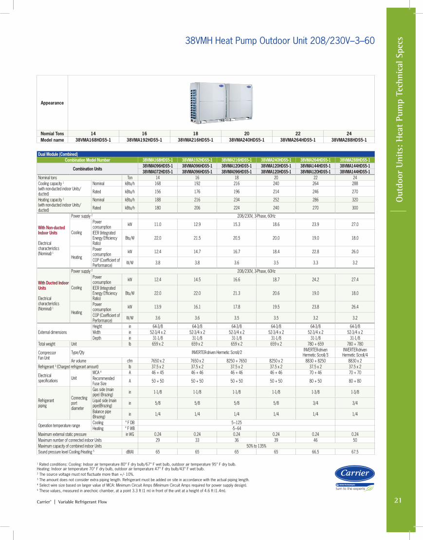
pecs38VMH Heat Pump Outdoor Unit 208/230V–3–60
Dual Module (Combined)Combination Model Number 38VMA168HDS5-1 38VMA192HDS5-1 38VMA216HDS5-1 38VMA240HDS5-1 38VMA264HDS5-1 38VMA288HDS5-1
Combination Units38VMA096HDS5-1 38VMA096HDS5-1 38VMA120HDS5-1 38VMA120HDS5-1 38VMA144HDS5-1 38VMA144HDS5-138VMA072HDS5-1 38VMA096HDS5-1 38VMA096HDS5-1 38VMA120HDS5-1 38VMA120HDS5-1 38VMA144HDS5-1
Nominal tons Ton 14 16 18 20 22 24Cooling capacity 1 (with non-ducted indoor Units/ducted)
Nominal kBtu/h 168 192 216 240 264 288
Rated kBtu/h 156 176 196 214 246 270
Heating capacity 1 (with non-ducted indoor Units/ducted)
Nominal kBtu/h 188 216 234 252 286 320
Rated kBtu/h 180 206 224 240 270 300
With Non-ducted Indoor Units Electrical characteristics (Nominal) 1
Power supply 2 208/230V, 3-Phase, 60Hz
Cooling
Power consumption kW 11.0 12.9 15.3 18.6 23.9 27.0
IEER (Integrated Energy Efficiency Ratio)
Btu/W 22.0 21.5 20.5 20.0 19.0 18.0
Heating
Power consumption kW 12.4 14.7 16.7 18.4 22.8 26.0
COP (Coefficient of Performance) W/W 3.8 3.8 3.6 3.5 3.3 3.2
With Ducted Indoor Units Electrical characteristics (Nominal) 1
Power supply 2 208/230V, 3-Phase, 60Hz
Cooling
Power consumption kW 12.4 14.5 16.6 18.7 24.2 27.4
IEER (Integrated Energy Efficiency Ratio)
Btu/W 22.0 22.0 21.3 20.6 19.0 18.0
Heating
Power consumption kW 13.9 16.1 17.8 19.5 23.8 26.4
COP (Coefficient of Performance) W/W 3.6 3.6 3.5 3.5 3.2 3.2
External dimensionsHeight in 64-3/8 64-3/8 64-3/8 64-3/8 64-3/8 64-3/8Width in 52-3/4 x 2 52-3/4 x 2 52-3/4 x 2 52-3/4 x 2 52-3/4 x 2 52-3/4 x 2Depth in 31-1/8 31-1/8 31-1/8 31-1/8 31-1/8 31-1/8
Total weight Unit lb 659 x 2 659 x 2 659 x 2 659 x 2 780 + 659 780 + 780
CompressorFan Unit
Type/Qty INVERTER-driven Hermetic Scroll/2 INVERTER-driven Hermetic Scroll/3
INVERTER-driven Hermetic Scroll/4
Air volume cfm 7650 x 2 7650 x 2 8250 + 7650 8250 x 2 8830 + 8250 8830 x 2Refrigerant 3 (Charged refrigerant amount) lb 37.5 x 2 37.5 x 2 37.5 x 2 37.5 x 2 37.5 x 2 37.5 x 2
Electrical specifications Unit
MCA 4 A 46 + 45 46 + 46 46 + 46 46 + 46 70 + 46 70 + 70Recommended Fuse Size A 50 + 50 50 + 50 50 + 50 50 + 50 80 + 50 80 + 80
Refrigerant piping
Connecting port diameter
Gas side (main pipe) (Brazing) in 1-1/8 1-1/8 1-1/8 1-1/8 1-3/8 1-3/8
Liquid side (main pipe)(Brazing) in 5/8 5/8 5/8 5/8 3/4 3/4
Balance pipe (Brazing) in 1/4 1/4 1/4 1/4 1/4 1/4
Operation temperature rangeCooling ° F DB 5~125Heating ° F WB -5~64
Maximum external static pressure in WG 0.24 0.24 0.24 0.24 0.24 0.24Maximum number of connected indoor Units 29 33 36 39 46 50Maximum capacity of combined indoor Units 50% to 135%Sound pressure level Cooling/Heating 5 dB(A) 65 65 65 65 66.5 67.5
Appearance
Nomial Tons 14 16 18 20 22 24Model name 38VMA168HDS5-1 38VMA192HDS5-1 38VMA216HDS5-1 38VMA240HDS5-1 38VMA264HDS5-1 38VMA288HDS5-1
1 Rated conditions: Cooling: Indoor air temperature 80° F dry bulb/67° F wet bulb, outdoor air temperature 95° F dry bulb. Heating: Indoor air temperature 70° F dry bulb, outdoor air temperature 47° F dry bulb/43° F wet bulb. 2 The source voltage must not fluctuate more than +/- 10%.3 The amount does not consider extra piping length. Refrigerant must be added on site in accordance with the actual piping length.4 Select wire size based on larger value of MCA: Minimum Circuit Amps (Minimum Circuit Amps required for power supply design).5 These values, measured in anechoic chamber, at a point 3.3 ft (1 m) in front of the unit at a height of 4.6 ft (1.4m).
22 Carrier® | Variable Refrigerant Flow
Outdoor U
nits: Heat Pum
p Technical Specs
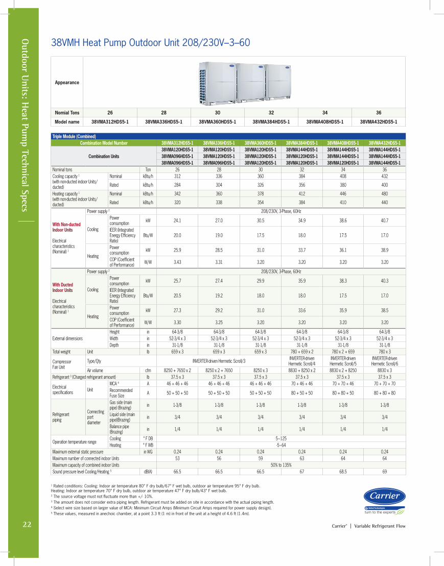
38VMH Heat Pump Outdoor Unit 208/230V–3–60
Appearance
Nomial Tons 26 28 30 32 34 36
Model name 38VMA312HDS5-1 38VMA336HDS5-1 38VMA360HDS5-1 38VMA384HDS5-1 38VMA408HDS5-1 38VMA432HDS5-1
Triple Module (Combined)Combination Model Number 38VMA312HDS5-1 38VMA336HDS5-1 38VMA360HDS5-1 38VMA384HDS5-1 38VMA408HDS5-1 38VMA432HDS5-1
Combination Units38VMA120HDS5-1 38VMA120HDS5-1 38VMA120HDS5-1 38VMA144HDS5-1 38VMA144HDS5-1 38VMA144HDS5-138VMA096HDS5-1 38VMA120HDS5-1 38VMA120HDS5-1 38VMA120HDS5-1 38VMA144HDS5-1 38VMA144HDS5-138VMA096HDS5-1 38VMA096HDS5-1 38VMA120HDS5-1 38VMA120HDS5-1 38VMA120HDS5-1 38VMA144HDS5-1
Nominal tons Ton 26 28 30 32 34 36Cooling capacity 1 (with non-ducted indoor Units/ducted)
Nominal kBtu/h 312 336 360 384 408 432
Rated kBtu/h 284 304 326 356 380 400
Heating capacity 1 (with non-ducted indoor Units/ducted)
Nominal kBtu/h 342 360 378 412 446 480
Rated kBtu/h 320 338 354 384 410 440
With Non-ducted Indoor Units Electrical characteristics (Nominal) 1
Power supply 2 208/230V, 3-Phase, 60Hz
Cooling
Power consumption kW 24.1 27.0 30.5 34.9 38.6 40.7
IEER (Integrated Energy Efficiency Ratio)
Btu/W 20.0 19.0 17.5 18.0 17.5 17.0
Heating
Power consumption kW 25.9 28.5 31.0 33.7 36.1 38.9
COP (Coefficient of Performance) W/W 3.43 3.31 3.20 3.20 3.20 3.20
With Ducted Indoor Units Electrical characteristics (Nominal) 1
Power supply 2 208/230V, 3-Phase, 60Hz
Cooling
Power consumption kW 25.7 27.4 29.9 35.9 38.3 40.3
IEER (Integrated Energy Efficiency Ratio)
Btu/W 20.5 19.2 18.0 18.0 17.5 17.0
Heating
Power consumption kW 27.3 29.2 31.0 33.6 35.9 38.5
COP (Coefficient of Performance) W/W 3.30 3.25 3.20 3.20 3.20 3.20
External dimensionsHeight in 64-3/8 64-3/8 64-3/8 64-3/8 64-3/8 64-3/8Width in 52-3/4 x 3 52-3/4 x 3 52-3/4 x 3 52-3/4 x 3 52-3/4 x 3 52-3/4 x 3Depth in 31-1/8 31-1/8 31-1/8 31-1/8 31-1/8 31-1/8
Total weight Unit lb 659 x 3 659 x 3 659 x 3 780 + 659 x 2 780 x 2 + 659 780 x 3
CompressorFan Unit
Type/Qty INVERTER-driven Hermetic Scroll/3 INVERTER-driven Hermetic Scroll/4
INVERTER-driven Hermetic Scroll/5
INVERTER-driven Hermetic Scroll/6
Air volume cfm 8250 + 7650 x 2 8250 x 2 + 7650 8250 x 3 8830 + 8250 x 2 8830 x 2 + 8250 8830 x 3Refrigerant 3 (Charged refrigerant amount) lb 37.5 x 3 37.5 x 3 37.5 x 3 37.5 x 3 37.5 x 3 37.5 x 3
Electrical specifications Unit
MCA 4 A 46 + 46 + 46 46 + 46 + 46 46 + 46 + 46 70 + 46 + 46 70 + 70 + 46 70 + 70 + 70Recommended Fuse Size A 50 + 50 + 50 50 + 50 + 50 50 + 50 + 50 80 + 50 + 50 80 + 80 + 50 80 + 80 + 80
Refrigerant piping
Connecting port diameter
Gas side (main pipe) (Brazing) in 1-3/8 1-3/8 1-3/8 1-3/8 1-3/8 1-3/8
Liquid side (main pipe)(Brazing) in 3/4 3/4 3/4 3/4 3/4 3/4
Balance pipe (Brazing) in 1/4 1/4 1/4 1/4 1/4 1/4
Operation temperature rangeCooling ° F DB 5~125Heating ° F WB -5~64
Maximum external static pressure in WG 0.24 0.24 0.24 0.24 0.24 0.24Maximum number of connected indoor Units 53 56 59 63 64 64Maximum capacity of combined indoor Units 50% to 135%Sound pressure level Cooling/Heating 5 dB(A) 66.5 66.5 66.5 67 68.5 69
1 Rated conditions: Cooling: Indoor air temperature 80° F dry bulb/67° F wet bulb, outdoor air temperature 95° F dry bulb. Heating: Indoor air temperature 70° F dry bulb, outdoor air temperature 47° F dry bulb/43° F wet bulb. 2 The source voltage must not fluctuate more than +/- 10%.3 The amount does not consider extra piping length. Refrigerant must be added on site in accordance with the actual piping length.4 Select wire size based on larger value of MCA: Minimum Circuit Amps (Minimum Circuit Amps required for power supply design).5 These values, measured in anechoic chamber, at a point 3.3 ft (1 m) in front of the unit at a height of 4.6 ft (1.4m).
23Carrier® | Variable Refrigerant Flow
Out
door
Uni
ts: H
eat
Pum
p Te
chni
cal S
pecs38VMH Heat Pump Outdoor Unit 460V–3–60
Technical Specifications
Appearance
Multi-ports 6 8 10 12
Model name 38VMA072HDS6-1 38VMA096HDS6-1 38VMA120HDS6-1 38VMA144HDS6-1
Single ModuleOutdoor Unit Model Name 38VMA072HDS6-1 38VMA096HDS6-1 38VMA120HDS6-1 38VMA144HDS6-1Nominal tons Ton 6 8 10 12Cooling capacity 1 (with non-ducted indoor Units/ducted)
Nominal kBtu/h 72 96 120 144
Rated kBtu/h 69 92 112 136
Heating capacity 1 (with non-ducted indoor Units/ducted)
Nominal kBtu/h 80 108 126 160
Rated kBtu/h 77 103 120 150
With Non-ducted Indoor Units Electrical characteristics (Nominal) (*1)
Power supply 2 460V, 3-Phase, 60Hz
CoolingPower consumption kW 4.1 6.2 8.8 12.1 IEER (Integrated Energy Efficiency Ratio) Btu/W 22.5 23.5 22.5 19.5
HeatingPower consumption kW 4.5 7.2 9.0 12.1 COP (Coefficient of Performance) W/W 4.3 3.8 3.6 3.4
With Ducted Indoor Units Electrical characteristics (Nominal) (*1)
Power supply 2 460V, 3-Phase, 60Hz
CoolingPower consumption kW 5.1 7.5 9.6 12.3 IEER (Integrated Energy Efficiency Ratio) Btu/W 23.6 23 21.9 19.5
HeatingPower consumption kW 5.6 8.0 9.8 12.6 COP (Coefficient of Performance) W/W 3.9 3.6 3.5 3.4
External dimensionsHeight in 64-3/8Width in 52-3/4Depth in 31-1/8
Total weight Unit lb 659 659 659 772
Compressor
Fan Unit
Type/Qty INVERTER-driven Hermetic Scroll/1 INVERTER-driven Hermetic Scroll/2
Air volume cfm 7650 7650 8250 8830Refrigerant 3 (Charged refrigerant amount) lb 37.5 37.5 37.5 37.5
Electrical specifications Unit
MCA 4 A 22 25 25 33Recommended Fuse Size A 25 30 30 35
Refrigerant piping
Connecting port diameter
Gas side (main pipe) (Brazing) in 7/8 7/8 1-1/8 1-1/8
Liquid side (main pipe)(Brazing) in 3/8 3/8 1/2 1/2
Balance pipe (Brazing) in 1/4 1/4 1/4 1/4
Operation temperature rangeCooling ° F DB 5~125Heating ° F WB -5~64
Maximum external static pressure in WG 0.24 0.24 0.24 0.24Maximum number of connected indoor Units 13 16 20 26Maximum capacity of combined indoor Units 50% to 135%Sound pressure level Cooling/Heating 5 dB(A) 62.5 63 63 65.5
1 Rated conditions: Cooling: Indoor air temperature 80° F dry bulb/67° F wet bulb, outdoor air temperature 95° F dry bulb. Heating: Indoor air temperature 70° F dry bulb, outdoor air temperature 47° F dry bulb/43° F wet bulb. 2 The source voltage must not fluctuate more than +/- 10%.3 The amount does not consider extra piping length. Refrigerant must be added on site in accordance with the actual piping length.4 Select wire size based on larger value of MCA: Minimum Circuit Amps (Minimum Circuit Amps required for power supply design).5 These values, measured in anechoic chamber, at a point 3.3 ft (1 m) in front of the unit at a height of 4.6 ft (1.4m).
24 Carrier® | Variable Refrigerant Flow
Outdoor U
nits: Heat Pum
p Technical Specs
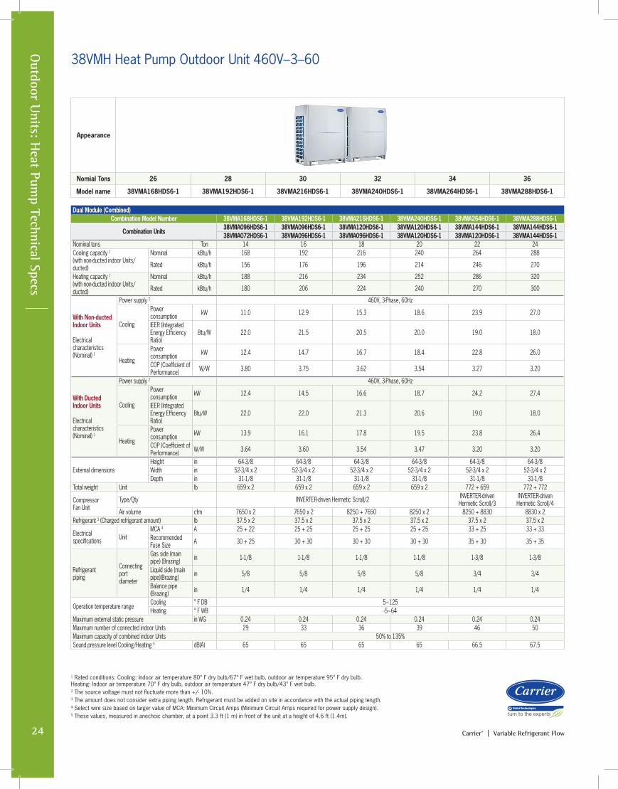
38VMH Heat Pump Outdoor Unit 460V–3–60
Appearance
Nomial Tons 26 28 30 32 34 36
Model name 38VMA168HDS6-1 38VMA192HDS6-1 38VMA216HDS6-1 38VMA240HDS6-1 38VMA264HDS6-1 38VMA288HDS6-1
Dual Module (Combined)Combination Model Number 38VMA168HDS6-1 38VMA192HDS6-1 38VMA216HDS6-1 38VMA240HDS6-1 38VMA264HDS6-1 38VMA288HDS6-1
Combination Units38VMA096HDS6-1 38VMA096HDS6-1 38VMA120HDS6-1 38VMA120HDS6-1 38VMA144HDS6-1 38VMA144HDS6-138VMA072HDS6-1 38VMA096HDS6-1 38VMA096HDS6-1 38VMA120HDS6-1 38VMA120HDS6-1 38VMA144HDS6-1
Nominal tons Ton 14 16 18 20 22 24Cooling capacity 1 (with non-ducted indoor Units/ducted)
Nominal kBtu/h 168 192 216 240 264 288
Rated kBtu/h 156 176 196 214 246 270
Heating capacity 1 (with non-ducted indoor Units/ducted)
Nominal kBtu/h 188 216 234 252 286 320
Rated kBtu/h 180 206 224 240 270 300
With Non-ducted Indoor Units Electrical characteristics (Nominal) 1
Power supply 2 460V, 3-Phase, 60Hz
Cooling
Power consumption kW 11.0 12.9 15.3 18.6 23.9 27.0
IEER (Integrated Energy Efficiency Ratio)
Btu/W 22.0 21.5 20.5 20.0 19.0 18.0
Heating
Power consumption kW 12.4 14.7 16.7 18.4 22.8 26.0
COP (Coefficient of Performance) W/W 3.80 3.75 3.62 3.54 3.27 3.20
With Ducted Indoor Units Electrical characteristics (Nominal) 1
Power supply 2 460V, 3-Phase, 60Hz
Cooling
Power consumption kW 12.4 14.5 16.6 18.7 24.2 27.4
IEER (Integrated Energy Efficiency Ratio)
Btu/W 22.0 22.0 21.3 20.6 19.0 18.0
Heating
Power consumption kW 13.9 16.1 17.8 19.5 23.8 26.4
COP (Coefficient of Performance) W/W 3.64 3.60 3.54 3.47 3.20 3.20
External dimensionsHeight in 64-3/8 64-3/8 64-3/8 64-3/8 64-3/8 64-3/8Width in 52-3/4 x 2 52-3/4 x 2 52-3/4 x 2 52-3/4 x 2 52-3/4 x 2 52-3/4 x 2Depth in 31-1/8 31-1/8 31-1/8 31-1/8 31-1/8 31-1/8
Total weight Unit lb 659 x 2 659 x 2 659 x 2 659 x 2 772 + 659 772 + 772
CompressorFan Unit
Type/Qty INVERTER-driven Hermetic Scroll/2 INVERTER-driven Hermetic Scroll/3
INVERTER-driven Hermetic Scroll/4
Air volume cfm 7650 x 2 7650 x 2 8250 + 7650 8250 x 2 8250 + 8830 8830 x 2Refrigerant 3 (Charged refrigerant amount) lb 37.5 x 2 37.5 x 2 37.5 x 2 37.5 x 2 37.5 x 2 37.5 x 2
Electrical specifications Unit
MCA 4 A 25 + 22 25 + 25 25 + 25 25 + 25 33 + 25 33 + 33Recommended Fuse Size A 30 + 25 30 + 30 30 + 30 30 + 30 35 + 30 35 + 35
Refrigerant piping
Connecting port diameter
Gas side (main pipe) (Brazing) in 1-1/8 1-1/8 1-1/8 1-1/8 1-3/8 1-3/8
Liquid side (main pipe)(Brazing) in 5/8 5/8 5/8 5/8 3/4 3/4
Balance pipe (Brazing) in 1/4 1/4 1/4 1/4 1/4 1/4
Operation temperature rangeCooling ° F DB 5~125Heating ° F WB -5~64
Maximum external static pressure in WG 0.24 0.24 0.24 0.24 0.24 0.24Maximum number of connected indoor Units 29 33 36 39 46 50Maximum capacity of combined indoor Units 50% to 135%Sound pressure level Cooling/Heating 5 dB(A) 65 65 65 65 66.5 67.5
1 Rated conditions: Cooling: Indoor air temperature 80° F dry bulb/67° F wet bulb, outdoor air temperature 95° F dry bulb. Heating: Indoor air temperature 70° F dry bulb, outdoor air temperature 47° F dry bulb/43° F wet bulb. 2 The source voltage must not fluctuate more than +/- 10%.3 The amount does not consider extra piping length. Refrigerant must be added on site in accordance with the actual piping length.4 Select wire size based on larger value of MCA: Minimum Circuit Amps (Minimum Circuit Amps required for power supply design).5 These values, measured in anechoic chamber, at a point 3.3 ft (1 m) in front of the unit at a height of 4.6 ft (1.4m).
25Carrier® | Variable Refrigerant Flow
Out
door
Uni
ts: H
eat
Pum
p Te
chni
cal S
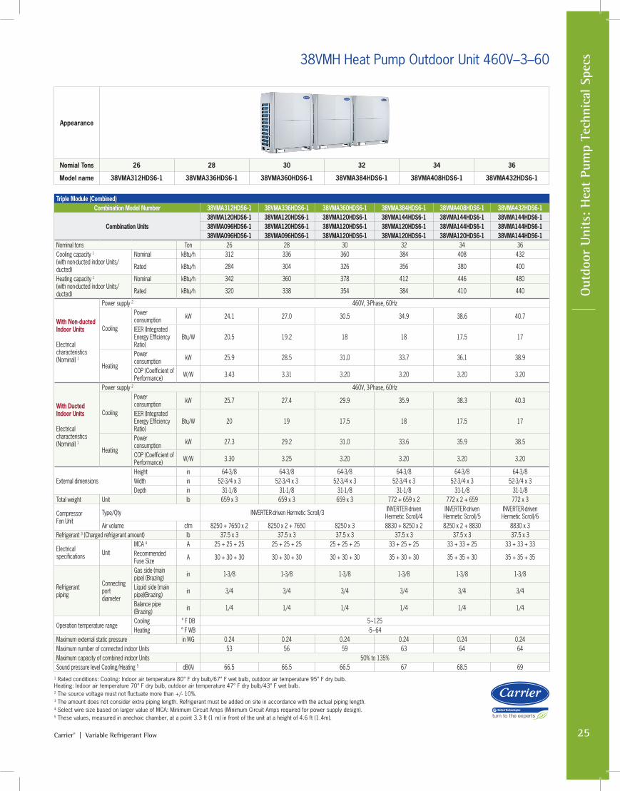
pecs38VMH Heat Pump Outdoor Unit 460V–3–60
Appearance
Nomial Tons 26 28 30 32 34 36
Model name 38VMA312HDS6-1 38VMA336HDS6-1 38VMA360HDS6-1 38VMA384HDS6-1 38VMA408HDS6-1 38VMA432HDS6-1
Triple Module (Combined)Combination Model Number 38VMA312HDS6-1 38VMA336HDS6-1 38VMA360HDS6-1 38VMA384HDS6-1 38VMA408HDS6-1 38VMA432HDS6-1
Combination Units38VMA120HDS6-1 38VMA120HDS6-1 38VMA120HDS6-1 38VMA144HDS6-1 38VMA144HDS6-1 38VMA144HDS6-138VMA096HDS6-1 38VMA120HDS6-1 38VMA120HDS6-1 38VMA120HDS6-1 38VMA144HDS6-1 38VMA144HDS6-138VMA096HDS6-1 38VMA096HDS6-1 38VMA120HDS6-1 38VMA120HDS6-1 38VMA120HDS6-1 38VMA144HDS6-1
Nominal tons Ton 26 28 30 32 34 36Cooling capacity 1 (with non-ducted indoor Units/ducted)
Nominal kBtu/h 312 336 360 384 408 432
Rated kBtu/h 284 304 326 356 380 400
Heating capacity 1 (with non-ducted indoor Units/ducted)
Nominal kBtu/h 342 360 378 412 446 480
Rated kBtu/h 320 338 354 384 410 440
With Non-ducted Indoor Units Electrical characteristics (Nominal) 1
Power supply 2 460V, 3-Phase, 60Hz
Cooling
Power consumption kW 24.1 27.0 30.5 34.9 38.6 40.7
IEER (Integrated Energy Efficiency Ratio)
Btu/W 20.5 19.2 18 18 17.5 17
Heating
Power consumption kW 25.9 28.5 31.0 33.7 36.1 38.9
COP (Coefficient of Performance) W/W 3.43 3.31 3.20 3.20 3.20 3.20
With Ducted Indoor Units Electrical characteristics (Nominal) 1
Power supply 2 460V, 3-Phase, 60Hz
Cooling
Power consumption kW 25.7 27.4 29.9 35.9 38.3 40.3
IEER (Integrated Energy Efficiency Ratio)
Btu/W 20 19 17.5 18 17.5 17
Heating
Power consumption kW 27.3 29.2 31.0 33.6 35.9 38.5
COP (Coefficient of Performance) W/W 3.30 3.25 3.20 3.20 3.20 3.20
External dimensionsHeight in 64-3/8 64-3/8 64-3/8 64-3/8 64-3/8 64-3/8Width in 52-3/4 x 3 52-3/4 x 3 52-3/4 x 3 52-3/4 x 3 52-3/4 x 3 52-3/4 x 3Depth in 31-1/8 31-1/8 31-1/8 31-1/8 31-1/8 31-1/8
Total weight Unit lb 659 x 3 659 x 3 659 x 3 772 + 659 x 2 772 x 2 + 659 772 x 3
CompressorFan Unit
Type/Qty INVERTER-driven Hermetic Scroll/3 INVERTER-driven Hermetic Scroll/4
INVERTER-driven Hermetic Scroll/5
INVERTER-driven Hermetic Scroll/6
Air volume cfm 8250 + 7650 x 2 8250 x 2 + 7650 8250 x 3 8830 + 8250 x 2 8250 x 2 + 8830 8830 x 3Refrigerant 3 (Charged refrigerant amount) lb 37.5 x 3 37.5 x 3 37.5 x 3 37.5 x 3 37.5 x 3 37.5 x 3
Electrical specifications Unit
MCA 4 A 25 + 25 + 25 25 + 25 + 25 25 + 25 + 25 33 + 25 + 25 33 + 33 + 25 33 + 33 + 33Recommended Fuse Size A 30 + 30 + 30 30 + 30 + 30 30 + 30 + 30 35 + 30 + 30 35 + 35 + 30 35 + 35 + 35
Refrigerant piping
Connecting port diameter
Gas side (main pipe) (Brazing) in 1-3/8 1-3/8 1-3/8 1-3/8 1-3/8 1-3/8
Liquid side (main pipe)(Brazing) in 3/4 3/4 3/4 3/4 3/4 3/4
Balance pipe (Brazing) in 1/4 1/4 1/4 1/4 1/4 1/4
Operation temperature rangeCooling ° F DB 5~125Heating ° F WB -5~64
Maximum external static pressure in WG 0.24 0.24 0.24 0.24 0.24 0.24Maximum number of connected indoor Units 53 56 59 63 64 64Maximum capacity of combined indoor Units 50% to 135%Sound pressure level Cooling/Heating 5 dB(A) 66.5 66.5 66.5 67 68.5 69
1 Rated conditions: Cooling: Indoor air temperature 80° F dry bulb/67° F wet bulb, outdoor air temperature 95° F dry bulb. Heating: Indoor air temperature 70° F dry bulb, outdoor air temperature 47° F dry bulb/43° F wet bulb. 2 The source voltage must not fluctuate more than +/- 10%.3 The amount does not consider extra piping length. Refrigerant must be added on site in accordance with the actual piping length.4 Select wire size based on larger value of MCA: Minimum Circuit Amps (Minimum Circuit Amps required for power supply design).5 These values, measured in anechoic chamber, at a point 3.3 ft (1 m) in front of the unit at a height of 4.6 ft (1.4m).
Carrier® | Variable Refrigerant Flow Catalog26
Carrier® VRF Systems: Indoor Units
27Carrier® | Variable Refrigerant Flow
In
door
Uni
ts
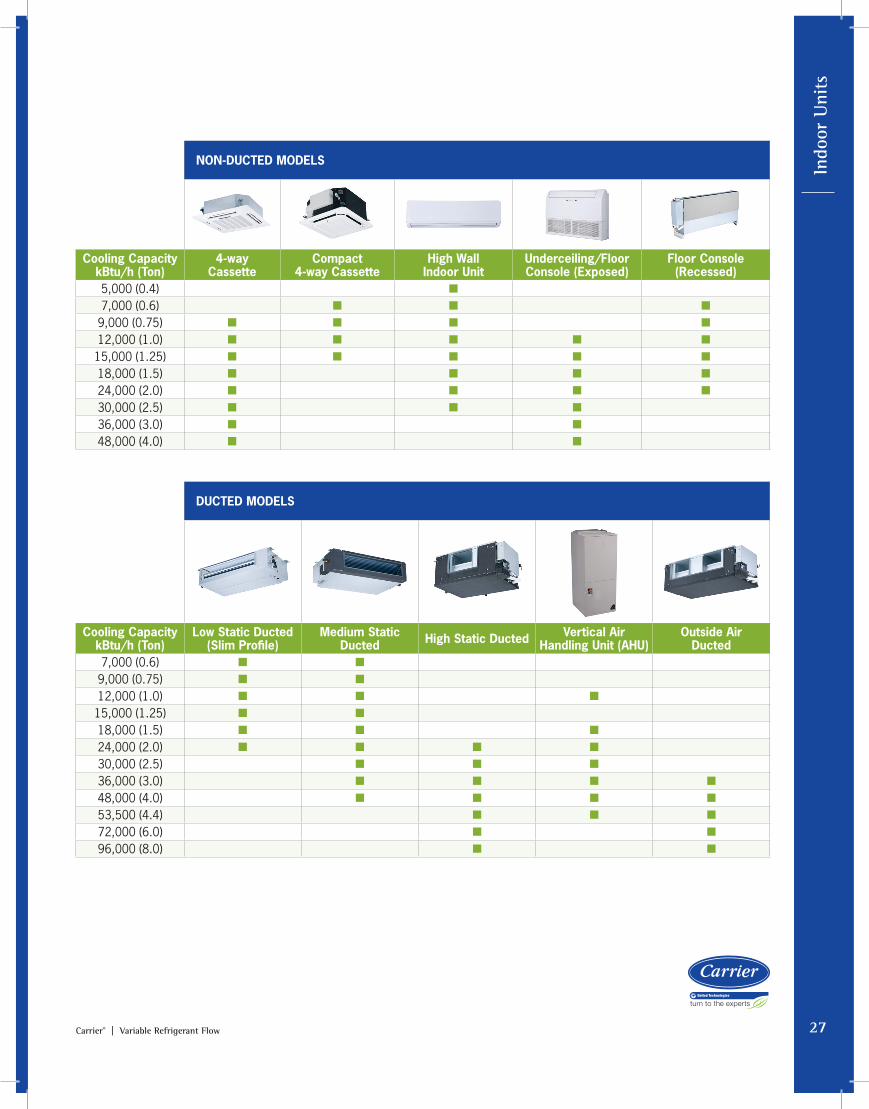
NON-DUCTED MODELS
Cooling Capacity kBtu/h (Ton)
4-way Cassette
Compact 4-way Cassette
High Wall Indoor Unit
Underceiling/Floor Console (Exposed)
Floor Console (Recessed)
5,000 (0.4) ■
7,000 (0.6) ■ ■ ■
9,000 (0.75) ■ ■ ■ ■
12,000 (1.0) ■ ■ ■ ■ ■
15,000 (1.25) ■ ■ ■ ■ ■
18,000 (1.5) ■ ■ ■ ■
24,000 (2.0) ■ ■ ■ ■
30,000 (2.5) ■ ■ ■
36,000 (3.0) ■ ■
48,000 (4.0) ■ ■
DUCTED MODELS
Cooling Capacity kBtu/h (Ton)
Low Static Ducted (Slim Profile)
Medium Static Ducted High Static Ducted Vertical Air
Handling Unit (AHU)Outside Air
Ducted7,000 (0.6) ■ ■
9,000 (0.75) ■ ■
12,000 (1.0) ■ ■ ■
15,000 (1.25) ■ ■
18,000 (1.5) ■ ■ ■
24,000 (2.0) ■ ■ ■ ■
30,000 (2.5) ■ ■ ■
36,000 (3.0) ■ ■ ■ ■
48,000 (4.0) ■ ■ ■ ■
53,500 (4.4) ■ ■ ■
72,000 (6.0) ■ ■
96,000 (8.0) ■ ■
28 Carrier® | Variable Refrigerant Flow
Unit 40VMF 40VMF009A--3 40VMF012A--3 40VMF015A--3 40VMF018A--3 40VMF024A--3 40VMF030A--3 40VMF036A--3 40VMF048A--3Power supply (V-Ph-Hz) 208/230-1-60
Cooling Capacity (Btuh) 9,000 12,000 15,000 19,100 24,000 30,000 36,000 48,000
Heating Capacity (Btuh) 10,900 13,600 17,000 21,500 27,000 34,000 40,000 54,000
Indoor fan motor
Type DC
Input (W) 40 54 67 153.5 85.4 131.7 182.7 202.3
Indoor airflow (cfm)
Low 330 390 460 610 610 680 800 950
Medium 390 460 560 700 700 800 950 1100
High 460 560 680 1000 800 950 1100 1200
Indoor unit sound level (dBA)
Low 32.1 33.0 37.0 40.2 40.2 42.1 47.3 50.5
Medium 34.0 37.3 41.5 43.1 42.5 45.1 50.4 54.0
High 36.7 41.4 45.6 52.5 44.7 49.5 53.9 55.4
Unit
Unit Dimension, W x H x D (in.) 33-1/8 x 9 x 33-1/8 33-1/8 x 11-3/4 x 33-1/8
Panel/Grille Dimensions W x H x D (in.)
37-3/8 x 1-3/4 x 37-3/8
Unit Net/Gross Weight (lb) w/Packaging
54/71 69/86
Panel/Grille Net/Gross Weight (lb) w/Packaging
13.2/20
Refrigerant type R410a
Expansion device Electronic Expansion Valve
Design Pressure, High/Low (psig) 580/320
Refrigerant piping (in.)
Liquid Side, OD (Flare) 1/4 3/8
Suction Side, OD (Flare) 1/2 5/8
Connecting Wiring
Power Wiring Sized per NEC and Local Codes based on Nameplate Electrical data
Signal Wiring 2-core stranded shielded twisted pair cable 18AWG
Condensate pipe diameter, OD (in.) 1-1/4
Condensate pump Included (up to 29.5")
Electrical data
MCA (A) 0.73 0.91 1.10 2.00 1.30 1.70 2.30 2.40
MOPD (A) 15
Indoor Units Technical Specs
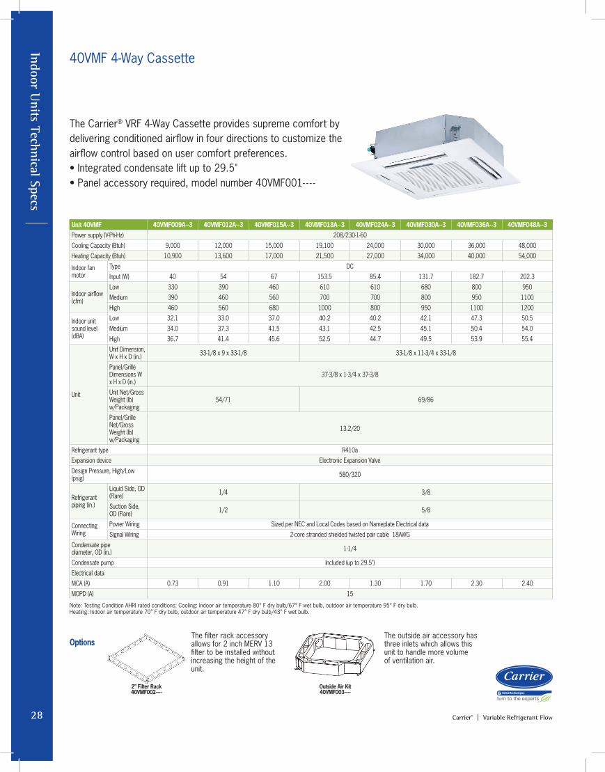
The Carrier® VRF 4-Way Cassette provides supreme comfort by delivering conditioned airflow in four directions to customize the airflow control based on user comfort preferences.• Integrated condensate lift up to 29.5"• Panel accessory required, model number 40VMF001- - - -
The filter rack accessory allows for 2 inch MERV 13 filter to be installed without increasing the height of the unit.
The outside air accessory has three inlets which allows this unit to handle more volume of ventilation air.
40VMF 4-Way Cassette
2” Filter Rack40VMF002----
Outside Air Kit40VMF003----
Options
Note: Testing Condition AHRI rated conditions: Cooling: Indoor air temperature 80° F dry bulb/67° F wet bulb, outdoor air temperature 95° F dry bulb. Heating: Indoor air temperature 70° F dry bulb, outdoor air temperature 47° F dry bulb/43° F wet bulb.
In
door
Uni
ts T
echn
ical
Spe
cs
29Carrier® | Variable Refrigerant Flow
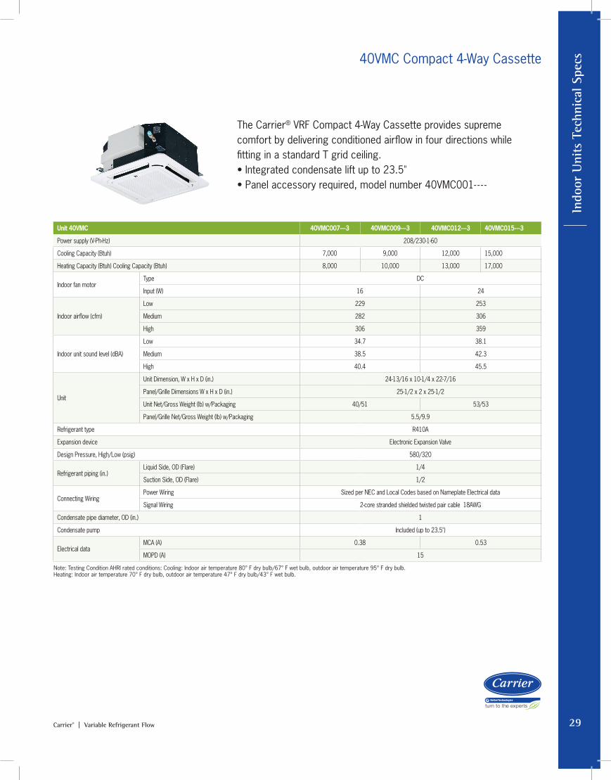
The Carrier® VRF Compact 4-Way Cassette provides supreme comfort by delivering conditioned airflow in four directions while fitting in a standard T grid ceiling.• Integrated condensate lift up to 23.5"• Panel accessory required, model number 40VMC001- - - -
40VMC Compact 4-Way Cassette
Unit 40VMC 40VMC007---3 40VMC009---3 40VMC012---3 40VMC015---3
Power supply (V-Ph-Hz) 208/230-1-60
Cooling Capacity (Btuh) 7,000 9,000 12,000 15,000
Heating Capacity (Btuh) Cooling Capacity (Btuh) 8,000 10,000 13,000 17,000
Indoor fan motor Type DC
Input (W) 16 24
Indoor airflow (cfm)
Low 229 253
Medium 282 306
High 306 359
Indoor unit sound level (dBA)
Low 34.7 38.1
Medium 38.5 42.3
High 40.4 45.5
Unit
Unit Dimension, W x H x D (in.) 24-13/16 x 10-1/4 x 22-7/16
Panel/Grille Dimensions W x H x D (in.) 25-1/2 x 2 x 25-1/2
Unit Net/Gross Weight (lb) w/Packaging 40/51 53/53
Panel/Grille Net/Gross Weight (lb) w/Packaging 5.5/9.9
Refrigerant type R410A
Expansion device Electronic Expansion Valve
Design Pressure, High/Low (psig) 580/320
Refrigerant piping (in.) Liquid Side, OD (Flare) 1/4
Suction Side, OD (Flare) 1/2
Connecting WiringPower Wiring Sized per NEC and Local Codes based on Nameplate Electrical data
Signal Wiring 2-core stranded shielded twisted pair cable 18AWG
Condensate pipe diameter, OD (in.) 1
Condensate pump Included (up to 23.5")
Electrical dataMCA (A) 0.38 0.53
MOPD (A) 15
Note: Testing Condition AHRI rated conditions: Cooling: Indoor air temperature 80° F dry bulb/67° F wet bulb, outdoor air temperature 95° F dry bulb. Heating: Indoor air temperature 70° F dry bulb, outdoor air temperature 47° F dry bulb/43° F wet bulb.

Indoor Units Technical Specs
30 Carrier® | Variable Refrigerant Flow
The Carrier® VRF High Wall Unit mounts on the wall providing conditioned air to fit any type of space.• Filter is washable• Flared refrigerant pipe connections
40VMW High Wall Unit
Unit 40VMW 40VMW005---3 40VMW007---3 40VMW009---3 40VMW012---3 40VMW015---3 40VMW018---3 40VMW024---3 40VMW030---3
Power supply (V-Ph-Hz) 208/230-1-60
Cooling Capacity (Btuh) 5,000 7,500 9,500 12,000 15,000 18,000 24,000 30,000
Heating Capacity (Btuh) Cooling Capacity (Btuh) 6,000 8,500 10,900 13,500 17,000 21,000 27,000 34,000
Indoor fan motor
Type DC
Input (W) 11 25 30 35 45 75 85
Indoor airflow (cfm)
Low 245 245 250 380 440 460 480
Medium 245 270 280 420 470 530 600
High 245 320 360 480 560 650 770
Indoor unit sound level (dBA)
Low 31.7 31.2 31.8 32.8 38.4 38.9 36.8 38.1
Medium 31.7 32.2 32.6 34.6 39.6 40.2 42.0 43.6
High 31.7 34.0 34.5 36.4 41.7 41.8 43.2 48.3
Unit
Unit Dimension, W x H x D (in.)
36 x 11-3/8 x 9 42-1/4 x 12-3/8 x 9 47 x 13-1/2 x 10-1/8
Net/Gross Weight (lb) w/Packaging
28/35 32/40.5 38/50.5
Refrigerant type R410a
Expansion device Electronic Expansion Valve
Design Pressure, High/Low (psig) 580/320
Refrigerant piping (in.)
Liquid Side, OD (Flare) 1/4 3/8
Suction Side, OD (Flare) 1/2 5/8
Connecting Wiring
Power Wiring Sized per NEC and Local Codes based on Nameplate Electrical data
Signal Wiring 2-core stranded shielded twisted pair cable 18AWG
Condensate pipe diameter, OD (in.) 3/4
Electrical data
MCA (A) 0.29 0.45 0.86
MOPD (A) 15
Note: Testing Condition AHRI rated conditions: Cooling: Indoor air temperature 80° F dry bulb/67° F wet bulb, outdoor air temperature 95° F dry bulb. Heating: Indoor air temperature 70° F dry bulb, outdoor air temperature 47° F dry bulb/43° F wet bulb.

In
door
Uni
ts T
echn
ical
Spe
cs
31Carrier® | Variable Refrigerant Flow
The Carrier® VRF Underceiling Unit can be installed exposed below the ceiling or mounted to the floor standing as an exposed Floor Console Unit.• Condensate pump is accessory• Filter is washable
40VMU Underceiling Unit – Floor Console (Exposed)
Unit 40VMU 40VMU012---3 40VMU015---3 40VMU018---3 40VMU024---3 40VMU030---3 40VMU036---3 40VMU048---3
Power supply (V-Ph-Hz) 208/230-1-60
Cooling Capacity (Btuh) 12,000 15,000 18,000 24,000 30,000 36,000 48,000
Heating Capacity (Btuh) Cooling Capacity (Btuh) 13,500 17,000 21,000 27,000 34,000 40,000 54,000
Indoor fan motorType DC Motor
Input (W) 24 47 53 80 107 67 x 2 115 x 2
Indoor airflow (cfm)
Low 259 359 394 494 624 906 929
Medium 294 412 424 529 676 976 1000
High 335 441 471 571 729 1094 1353
Indoor unit sound level (dBA)
Low 35.8 41.7 44.1 50.2 50.4 48.4 50.6
Medium 37.7 45.4 46.5 52.0 52.1 50.3 52.3
High 40.5 47.2 48.5 53.8 53.9 53.0 59.8
Unit
Unit Dimension, W x H x D (in.) 39 x 26 x 8 50-1/2 x 26 x 8 66 x 27 x 10
Unit Net/Gross Weight (lb) w/Packaging 57/71 62/75 77/90 106/128
Refrigerant type R410a
Expansion device Electronic Expansion Valve
Design Pressure, High/Low (psig) 580/320
Refrigerant piping (in.)Liquid Side, OD (Flare) 1/4 3/8
Suction Side, OD (Flare) 1/2 5/8
Connecting WiringPower Wiring Sized per NEC and Local Codes based on Nameplate Electrical data
Signal Wiring 2-core stranded shielded twisted pair cable 18AWG
Condensate pipe diameter, OD (in.) 5/8
Electrical dataMCA (A) 0.44 0.73 0.87 1.20 1.40 1.80 2.80
MOPD (A) 15
Installation
Note: Testing Condition AHRI rated conditions: Cooling: Indoor air temperature 80° F dry bulb/67° F wet bulb, outdoor air temperature 95° F dry bulb. Heating: Indoor air temperature 70° F dry bulb, outdoor air temperature 47° F dry bulb/43° F wet bulb.
Indoor Units Technical Specs
32 Carrier® | Variable Refrigerant Flow
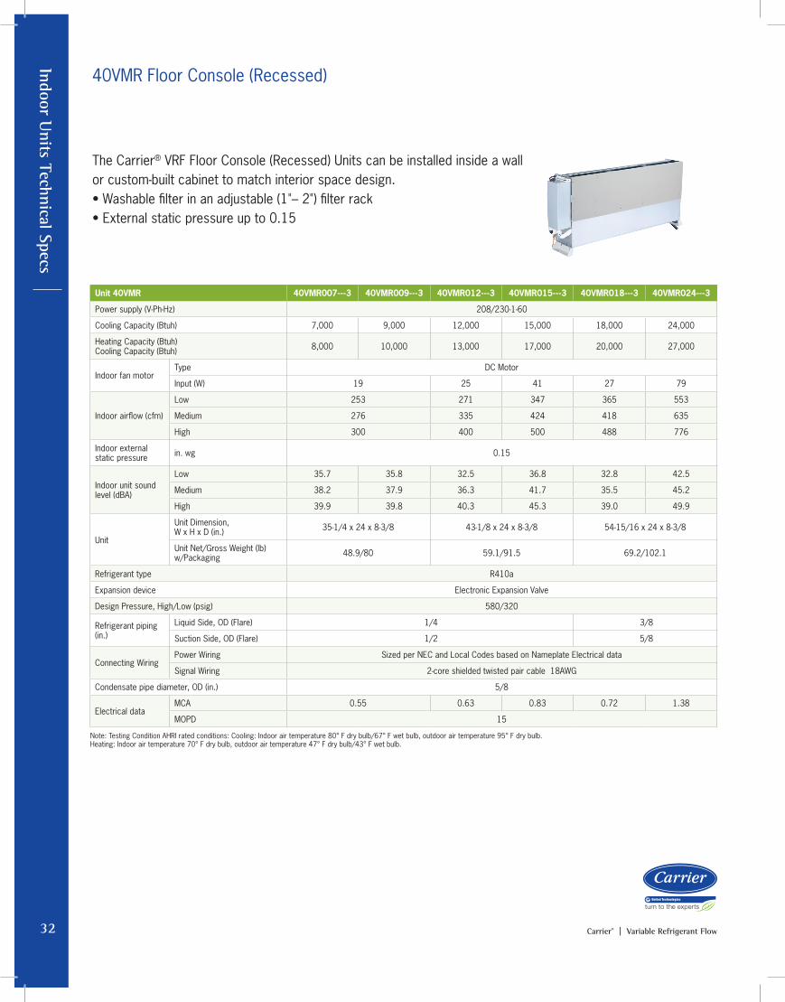
40VMR Floor Console (Recessed)
The Carrier® VRF Floor Console (Recessed) Units can be installed inside a wall or custom-built cabinet to match interior space design. • Washable filter in an adjustable (1"– 2") filter rack • External static pressure up to 0.15
Unit 40VMR 40VMR007---3 40VMR009---3 40VMR012---3 40VMR015---3 40VMR018---3 40VMR024---3
Power supply (V-Ph-Hz) 208/230-1-60
Cooling Capacity (Btuh) 7,000 9,000 12,000 15,000 18,000 24,000
Heating Capacity (Btuh) Cooling Capacity (Btuh) 8,000 10,000 13,000 17,000 20,000 27,000
Indoor fan motorType DC Motor
Input (W) 19 25 41 27 79
Indoor airflow (cfm)
Low 253 271 347 365 553
Medium 276 335 424 418 635
High 300 400 500 488 776
Indoor external static pressure in. wg 0.15
Indoor unit sound level (dBA)
Low 35.7 35.8 32.5 36.8 32.8 42.5
Medium 38.2 37.9 36.3 41.7 35.5 45.2
High 39.9 39.8 40.3 45.3 39.0 49.9
Unit
Unit Dimension, W x H x D (in.) 35-1/4 x 24 x 8-3/8 43-1/8 x 24 x 8-3/8 54-15/16 x 24 x 8-3/8
Unit Net/Gross Weight (lb)w/Packaging 48.9/80 59.1/91.5 69.2/102.1
Refrigerant type R410a
Expansion device Electronic Expansion Valve
Design Pressure, High/Low (psig) 580/320
Refrigerant piping (in.)
Liquid Side, OD (Flare) 1/4 3/8
Suction Side, OD (Flare) 1/2 5/8
Connecting WiringPower Wiring Sized per NEC and Local Codes based on Nameplate Electrical data
Signal Wiring 2-core shielded twisted pair cable 18AWG
Condensate pipe diameter, OD (in.) 5/8
Electrical dataMCA 0.55 0.63 0.83 0.72 1.38
MOPD 15
Note: Testing Condition AHRI rated conditions: Cooling: Indoor air temperature 80° F dry bulb/67° F wet bulb, outdoor air temperature 95° F dry bulb. Heating: Indoor air temperature 70° F dry bulb, outdoor air temperature 47° F dry bulb/43° F wet bulb.
In
door
Uni
ts T
echn
ical
Spe
cs
33Carrier® | Variable Refrigerant Flow
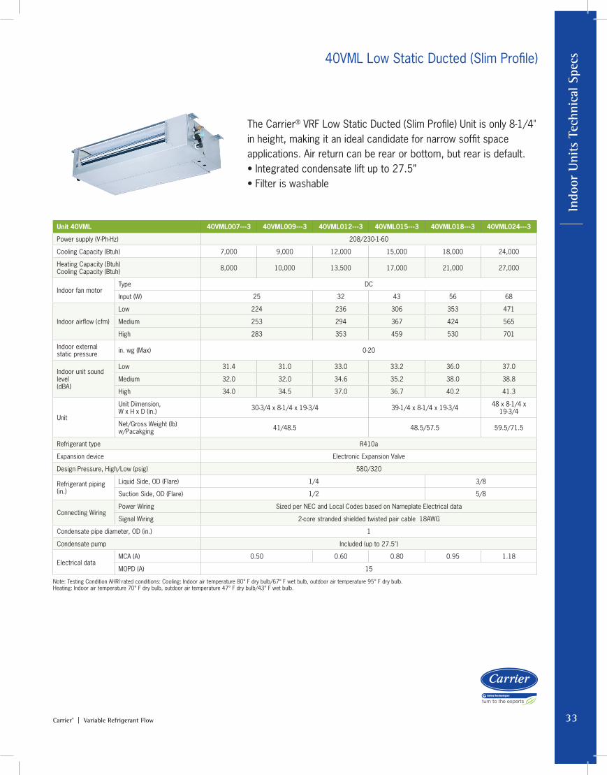
The Carrier® VRF Low Static Ducted (Slim Profile) Unit is only 8-1/4" in height, making it an ideal candidate for narrow soffit space applications. Air return can be rear or bottom, but rear is default.• Integrated condensate lift up to 27.5”• Filter is washable
40VML Low Static Ducted (Slim Profile)
Unit 40VML 40VML007---3 40VML009---3 40VML012---3 40VML015---3 40VML018---3 40VML024---3
Power supply (V-Ph-Hz) 208/230-1-60
Cooling Capacity (Btuh) 7,000 9,000 12,000 15,000 18,000 24,000
Heating Capacity (Btuh) Cooling Capacity (Btuh) 8,000 10,000 13,500 17,000 21,000 27,000
Indoor fan motor Type DC
Input (W) 25 32 43 56 68
Indoor airflow (cfm)
Low 224 236 306 353 471
Medium 253 294 367 424 565
High 283 353 459 530 701
Indoor external static pressure in. wg (Max) 0-20
Indoor unit sound level (dBA)
Low 31.4 31.0 33.0 33.2 36.0 37.0
Medium 32.0 32.0 34.6 35.2 38.0 38.8
High 34.0 34.5 37.0 36.7 40.2 41.3
Unit
Unit Dimension, W x H x D (in.) 30-3/4 x 8-1/4 x 19-3/4 39-1/4 x 8-1/4 x 19-3/4 48 x 8-1/4 x
19-3/4
Net/Gross Weight (lb)w/Pacakging 41/48.5 48.5/57.5 59.5/71.5
Refrigerant type R410a
Expansion device Electronic Expansion Valve
Design Pressure, High/Low (psig) 580/320
Refrigerant piping (in.)
Liquid Side, OD (Flare) 1/4 3/8
Suction Side, OD (Flare) 1/2 5/8
Connecting WiringPower Wiring Sized per NEC and Local Codes based on Nameplate Electrical data
Signal Wiring 2-core stranded shielded twisted pair cable 18AWG
Condensate pipe diameter, OD (in.) 1
Condensate pump Included (up to 27.5")
Electrical dataMCA (A) 0.50 0.60 0.80 0.95 1.18
MOPD (A) 15
Note: Testing Condition AHRI rated conditions: Cooling: Indoor air temperature 80° F dry bulb/67° F wet bulb, outdoor air temperature 95° F dry bulb. Heating: Indoor air temperature 70° F dry bulb, outdoor air temperature 47° F dry bulb/43° F wet bulb.
Indoor Units Technical Specs
34 Carrier® | Variable Refrigerant Flow
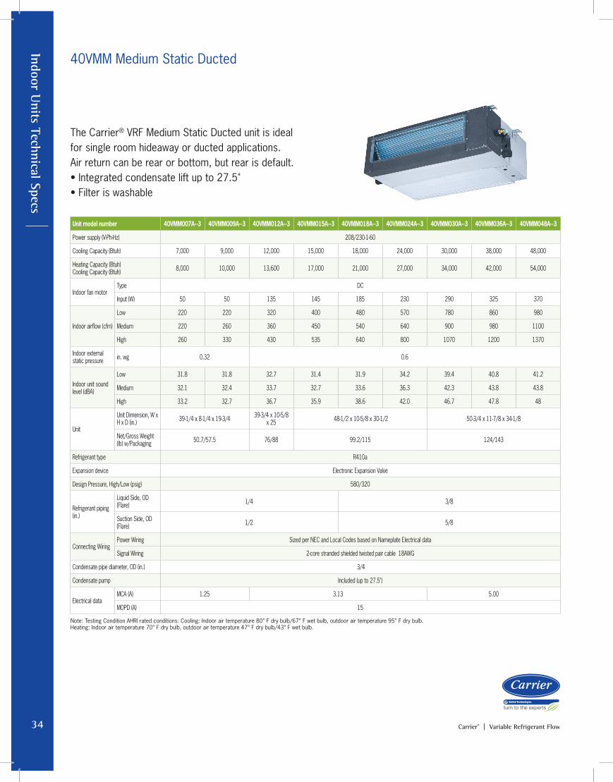
40VMM Medium Static Ducted
The Carrier® VRF Medium Static Ducted unit is ideal for single room hideaway or ducted applications.Air return can be rear or bottom, but rear is default.• Integrated condensate lift up to 27.5"• Filter is washable
Unit model number 40VMM007A--3 40VMM009A--3 40VMM012A--3 40VMM015A--3 40VMM018A--3 40VMM024A--3 40VMM030A--3 40VMM036A--3 40VMM048A--3
Power supply (V-Ph-Hz) 208/230-1-60
Cooling Capacity (Btuh) 7,000 9,000 12,000 15,000 18,000 24,000 30,000 38,000 48,000
Heating Capacity (Btuh) Cooling Capacity (Btuh) 8,000 10,000 13,600 17,000 21,000 27,000 34,000 42,000 54,000
Indoor fan motorType DC
Input (W) 50 50 135 145 185 230 290 325 370
Indoor airflow (cfm)
Low 220 220 320 400 480 570 780 860 980
Medium 220 260 360 450 540 640 900 980 1100
High 260 330 430 535 640 800 1070 1200 1370
Indoor external static pressure in. wg 0.32 0.6
Indoor unit sound level (dBA)
Low 31.8 31.8 32.7 31.4 31.9 34.2 39.4 40.8 41.2
Medium 32.1 32.4 33.7 32.7 33.6 36.3 42.3 43.8 43.8
High 33.2 32.7 36.7 35.9 38.6 42.0 46.7 47.8 48
Unit
Unit Dimension, W x H x D (in.) 39-1/4 x 8-1/4 x 19-3/4 39-3/4 x 10-5/8
x 25 48-1/2 x 10-5/8 x 30-1/2 50-3/4 x 11-7/8 x 34-1/8
Net/Gross Weight (lb) w/Packaging 50.7/57.5 76/88 99.2/115 124/143
Refrigerant type R410a
Expansion device Electronic Expansion Valve
Design Pressure, High/Low (psig) 580/320
Refrigerant piping (in.)
Liquid Side, OD (Flare) 1/4 3/8
Suction Side, OD (Flare) 1/2 5/8
Connecting WiringPower Wiring Sized per NEC and Local Codes based on Nameplate Electrical data
Signal Wiring 2-core stranded shielded twisted pair cable 18AWG
Condensate pipe diameter, OD (in.) 3/4
Condensate pump Included (up to 27.5")
Electrical dataMCA (A) 1.25 3.13 5.00
MOPD (A) 15
Note: Testing Condition AHRI rated conditions: Cooling: Indoor air temperature 80° F dry bulb/67° F wet bulb, outdoor air temperature 95° F dry bulb. Heating: Indoor air temperature 70° F dry bulb, outdoor air temperature 47° F dry bulb/43° F wet bulb.
In
door
Uni
ts T
echn
ical
Spe
cs
35Carrier® | Variable Refrigerant Flow
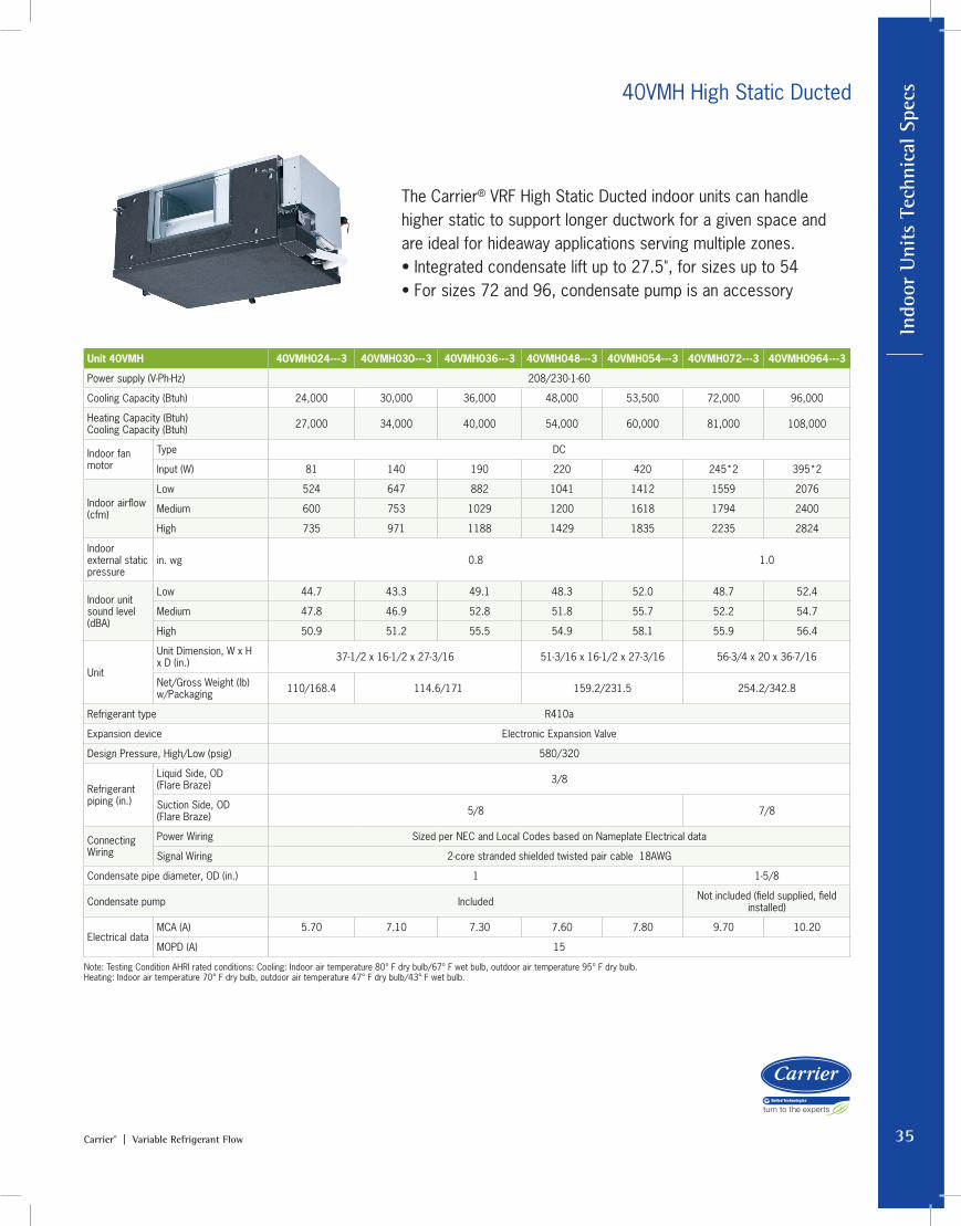
The Carrier® VRF High Static Ducted indoor units can handle higher static to support longer ductwork for a given space and are ideal for hideaway applications serving multiple zones.• Integrated condensate lift up to 27.5", for sizes up to 54• For sizes 72 and 96, condensate pump is an accessory
40VMH High Static Ducted
Unit 40VMH 40VMH024---3 40VMH030---3 40VMH036---3 40VMH048---3 40VMH054---3 40VMH072---3 40VMH0964---3
Power supply (V-Ph-Hz) 208/230-1-60
Cooling Capacity (Btuh) 24,000 30,000 36,000 48,000 53,500 72,000 96,000
Heating Capacity (Btuh) Cooling Capacity (Btuh) 27,000 34,000 40,000 54,000 60,000 81,000 108,000
Indoor fan motor
Type DC
Input (W) 81 140 190 220 420 245*2 395*2
Indoor airflow (cfm)
Low 524 647 882 1041 1412 1559 2076
Medium 600 753 1029 1200 1618 1794 2400
High 735 971 1188 1429 1835 2235 2824
Indoor external static pressure
in. wg 0.8 1.0
Indoor unit sound level (dBA)
Low 44.7 43.3 49.1 48.3 52.0 48.7 52.4
Medium 47.8 46.9 52.8 51.8 55.7 52.2 54.7
High 50.9 51.2 55.5 54.9 58.1 55.9 56.4
Unit
Unit Dimension, W x H x D (in.) 37-1/2 x 16-1/2 x 27-3/16 51-3/16 x 16-1/2 x 27-3/16 56-3/4 x 20 x 36-7/16
Net/Gross Weight (lb)w/Packaging 110/168.4 114.6/171 159.2/231.5 254.2/342.8
Refrigerant type R410a
Expansion device Electronic Expansion Valve
Design Pressure, High/Low (psig) 580/320
Refrigerant piping (in.)
Liquid Side, OD (Flare Braze) 3/8
Suction Side, OD (Flare Braze) 5/8 7/8
Connecting Wiring
Power Wiring Sized per NEC and Local Codes based on Nameplate Electrical data
Signal Wiring 2-core stranded shielded twisted pair cable 18AWG
Condensate pipe diameter, OD (in.) 1 1-5/8
Condensate pump Included Not included (field supplied, field installed)
Electrical dataMCA (A) 5.70 7.10 7.30 7.60 7.80 9.70 10.20
MOPD (A) 15
Note: Testing Condition AHRI rated conditions: Cooling: Indoor air temperature 80° F dry bulb/67° F wet bulb, outdoor air temperature 95° F dry bulb. Heating: Indoor air temperature 70° F dry bulb, outdoor air temperature 47° F dry bulb/43° F wet bulb.
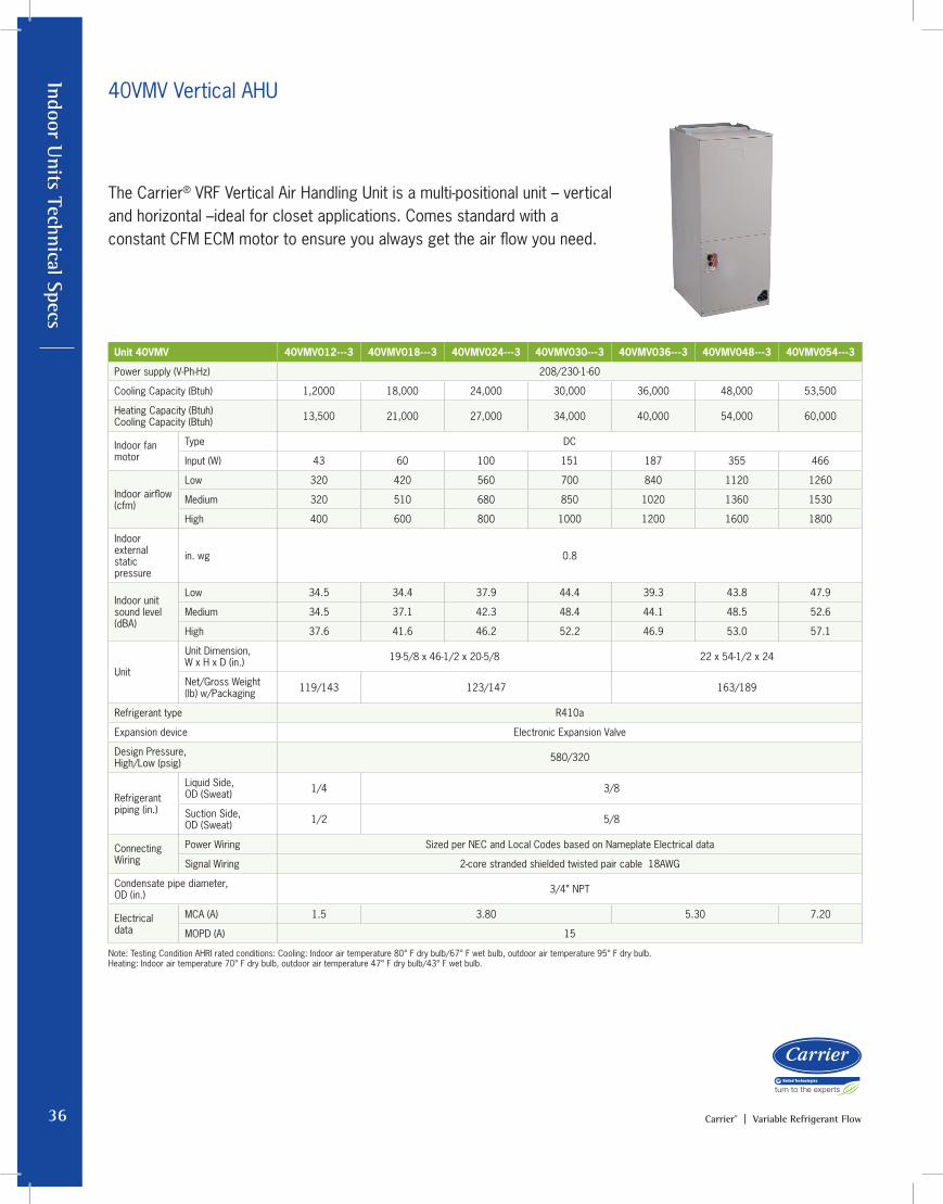
Indoor Units Technical Specs
36 Carrier® | Variable Refrigerant Flow
The Carrier® VRF Vertical Air Handling Unit is a multi-positional unit – vertical and horizontal –ideal for closet applications. Comes standard with a constant CFM ECM motor to ensure you always get the air flow you need.
40VMV Vertical AHU
Unit 40VMV 40VMV012---3 40VMV018---3 40VMV024---3 40VMV030---3 40VMV036---3 40VMV048---3 40VMV054---3
Power supply (V-Ph-Hz) 208/230-1-60
Cooling Capacity (Btuh) 1,2000 18,000 24,000 30,000 36,000 48,000 53,500
Heating Capacity (Btuh) Cooling Capacity (Btuh) 13,500 21,000 27,000 34,000 40,000 54,000 60,000
Indoor fan motor
Type DC
Input (W) 43 60 100 151 187 355 466
Indoor airflow (cfm)
Low 320 420 560 700 840 1120 1260
Medium 320 510 680 850 1020 1360 1530
High 400 600 800 1000 1200 1600 1800
Indoor external static pressure
in. wg 0.8
Indoor unit sound level (dBA)
Low 34.5 34.4 37.9 44.4 39.3 43.8 47.9
Medium 34.5 37.1 42.3 48.4 44.1 48.5 52.6
High 37.6 41.6 46.2 52.2 46.9 53.0 57.1
Unit
Unit Dimension, W x H x D (in.) 19-5/8 x 46-1/2 x 20-5/8 22 x 54-1/2 x 24
Net/Gross Weight (lb) w/Packaging 119/143 123/147 163/189
Refrigerant type R410a
Expansion device Electronic Expansion Valve
Design Pressure, High/Low (psig) 580/320
Refrigerant piping (in.)
Liquid Side, OD (Sweat) 1/4 3/8
Suction Side, OD (Sweat) 1/2 5/8
Connecting Wiring
Power Wiring Sized per NEC and Local Codes based on Nameplate Electrical data
Signal Wiring 2-core stranded shielded twisted pair cable 18AWG
Condensate pipe diameter, OD (in.) 3/4” NPT
Electrical data
MCA (A) 1.5 3.80 5.30 7.20
MOPD (A) 15
Note: Testing Condition AHRI rated conditions: Cooling: Indoor air temperature 80° F dry bulb/67° F wet bulb, outdoor air temperature 95° F dry bulb. Heating: Indoor air temperature 70° F dry bulb, outdoor air temperature 47° F dry bulb/43° F wet bulb.

In
door
Uni
ts T
echn
ical
Spe
cs
37Carrier® | Variable Refrigerant Flow
The Carrier® Outside Air unit draws in ventilation air into the space to provide outside air. The units are installed in plenum and can be connected to heat recovery and heat pump systems along with other styles of indoor unit.• Discharge temperature control• Integrated condensate lift up to 27.5"
40VMA Outside Air Ducted
Unit 40VMA 40VMA036---3 40VMA048---3 40VMA054---3 40VMA072---3 40VMA096---3
Power supply (V-Ph-Hz) 208/230-1-60
Cooling Capacity (Btuh) 36,000 48,000 53,500 72,000 96,000
Heating Capacity (Btuh) Cooling Capacity (Btuh) 24,000 30,000 36,000 47,000 59,000
Indoor fan motorType DC
Input (W) 64 71 87 60*2 80*2
Indoor airflow (cfm)
Low 441 471 529 882 1029
Medium 529 559 647 971 1176
High 588 647 765 1059 1294
Indoor external static pressure in. wg 0.8 1.0
Indoor unit sound level (dBA)
Low 43.8 43.4 43.9 48.5 47.7
Medium 47.8 47.8 47.8 50.0 50.8
High 49.5 50.4 51.4 52.1 53.5
UnitUnit Dimension, W x H x D (in.) 51-3/16 x 16-1/2 x 27-3/16 56-3/4 x 20 x 36-7/16
Net/Gross Weight (lb)w/Packaging 161.4/233.7 255.7/346.2
Refrigerant type R410a
Expansion device Electronic Expansion Valve
Design Pressure, High/Low (psig) 580/320
Refrigerant piping (in.)
Liquid Side, OD (Flare Braze) 3/8 3/8
Suction Side, OD (Flare Braze) 5/8 7/8
Connecting WiringPower Wiring Sized per NEC and Local Codes based on Nameplate Electrical data
Signal Wiring 2-core stranded shielded twisted pair cable 18AWG
Condensate pipe diameter, OD (in.) 1 1-5/8
Condensate pump Included (up to 27.5") Not included (field supplied, field installed)
Electrical dataMCA (A) 5.7 6.30 6.9 8.5 10.0
MOPD (A) 15
Note: Limits connected capacity at 30%
Note: Testing Condition AHRI rated conditions: Cooling: Indoor air temperature 80° F dry bulb/67° F wet bulb, outdoor air temperature 95° F dry bulb. Heating: Indoor air temperature 70° F dry bulb, outdoor air temperature 47° F dry bulb/43° F wet bulb.
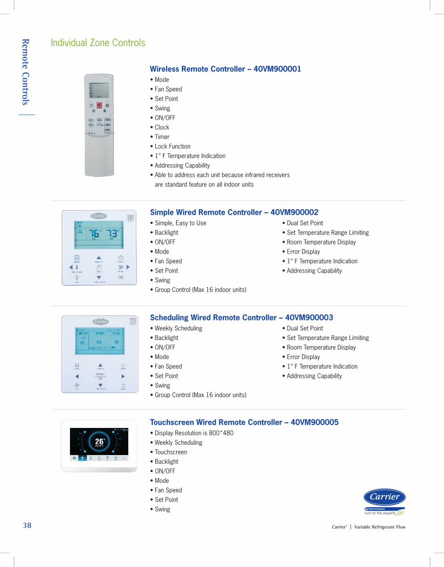
Remote Controls
38 Carrier® | Variable Refrigerant Flow
Individual Zone Controls
Wireless Remote Controller – 40VM900001• Mode• Fan Speed• Set Point• Swing• ON/OFF• Clock• Timer• Lock Function• 1° F Temperature Indication• Addressing Capability• Able to address each unit because infrared receivers
are standard feature on all indoor units
Simple Wired Remote Controller – 40VM900002• Simple, Easy to Use• Backlight• ON/OFF• Mode• Fan Speed• Set Point• Swing• Group Control (Max 16 indoor units)
• Dual Set Point• Set Temperature Range Limiting• Room Temperature Display• Error Display• 1° F Temperature Indication• Addressing Capability
Scheduling Wired Remote Controller – 40VM900003• Weekly Scheduling• Backlight• ON/OFF• Mode• Fan Speed• Set Point• Swing• Group Control (Max 16 indoor units)
• Dual Set Point• Set Temperature Range Limiting• Room Temperature Display• Error Display• 1° F Temperature Indication• Addressing Capability
Touchscreen Wired Remote Controller – 40VM900005• Display Resolution is 800*480 • Weekly Scheduling• Touchscreen• Backlight• ON/OFF• Mode• Fan Speed• Set Point• Swing
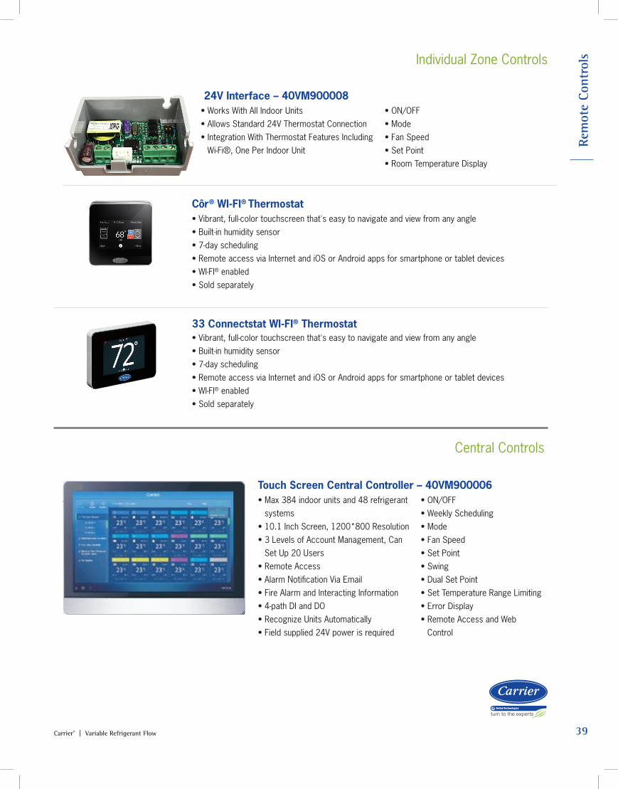
R
emot
e Co
ntro
ls
39Carrier® | Variable Refrigerant Flow
Individual Zone Controls
Côr® WI-FI® Thermostat• Vibrant, full-color touchscreen that's easy to navigate and view from any angle• Built-in humidity sensor• 7-day scheduling• Remote access via Internet and iOS or Android apps for smartphone or tablet devices• WI-FI® enabled • Sold separately
33 Connectstat WI-FI® Thermostat• Vibrant, full-color touchscreen that's easy to navigate and view from any angle• Built-in humidity sensor• 7-day scheduling• Remote access via Internet and iOS or Android apps for smartphone or tablet devices• WI-FI® enabled • Sold separately
Central Controls
Touch Screen Central Controller – 40VM900006• Max 384 indoor units and 48 refrigerant
systems• 10.1 Inch Screen, 1200*800 Resolution• 3 Levels of Account Management, Can
Set Up 20 Users• Remote Access• Alarm Notification Via Email• Fire Alarm and Interacting Information• 4-path DI and DO• Recognize Units Automatically• Field supplied 24V power is required
• ON/OFF• Weekly Scheduling• Mode• Fan Speed• Set Point• Swing• Dual Set Point• Set Temperature Range Limiting• Error Display• Remote Access and Web
Control
24V Interface – 40VM900008• Works With All Indoor Units• Allows Standard 24V Thermostat Connection• Integration With Thermostat Features Including
Wi-Fi®, One Per Indoor Unit
• ON/OFF• Mode• Fan Speed• Set Point• Room Temperature Display
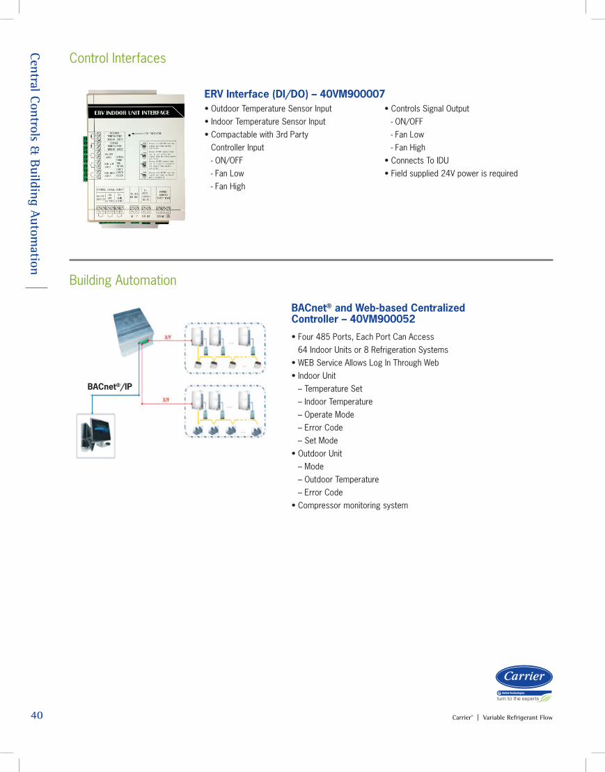
40 Carrier® | Variable Refrigerant Flow
Central Controls & B
uilding Automation
BACnet® and Web-based Centralized Controller – 40VM900052
• Four 485 Ports, Each Port Can Access 64 Indoor Units or 8 Refrigeration Systems• WEB Service Allows Log In Through Web• Indoor Unit – Temperature Set – Indoor Temperature – Operate Mode – Error Code – Set Mode • Outdoor Unit – Mode – Outdoor Temperature – Error Code• Compressor monitoring system
BACnet®/IP
Control Interfaces
ERV Interface (DI/DO) – 40VM900007• Outdoor Temperature Sensor Input • Indoor Temperature Sensor Input • Compactable with 3rd Party
Controller Input - ON/OFF
- Fan Low - Fan High
• Controls Signal Output - ON/OFF - Fan Low - Fan High• Connects To IDU• Field supplied 24V power is required
Building Automation
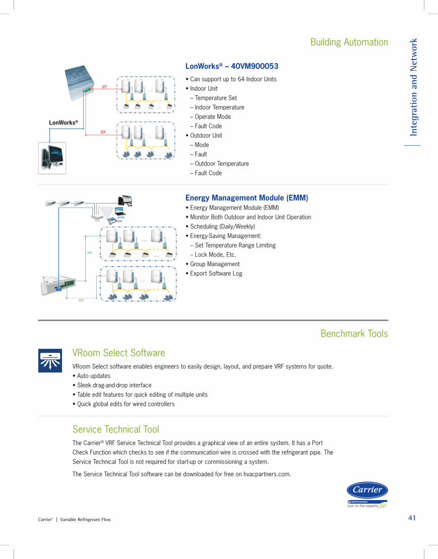
41Carrier® | Variable Refrigerant Flow
In
tegr
atio
n an
d N
etw
ork Building Automation
Benchmark Tools
LonWorks® – 40VM900053
• Can support up to 64 Indoor Units• Indoor Unit – Temperature Set – Indoor Temperature – Operate Mode – Fault Code• Outdoor Unit – Mode – Fault – Outdoor Temperature – Fault Code
LonWorks®
Energy Management Module (EMM)• Energy Management Module (EMM)• Monitor Both Outdoor and Indoor Unit Operation• Scheduling (Daily/Weekly)• Energy-Saving Management: – Set Temperature Range Limiting – Lock Mode, Etc.• Group Management• Export Software Log
Service Technical Tool The Carrier® VRF Service Technical Tool provides a graphical view of an entire system. It has a Port Check Function which checks to see if the communication wire is crossed with the refrigerant pipe. The Service Technical Tool is not required for start-up or commissioning a system.
The Service Technical Tool software can be downloaded for free on hvacpartners.com.
VRoom Select Software VRoom Select software enables engineers to easily design, layout, and prepare VRF systems for quote. • Auto updates• Sleek drag-and-drop interface• Table edit features for quick editing of multiple units• Quick global edits for wired controllers
A Century of Innovation
Since 1902, Carrier® has been the brand you’ve trusted for all your heating and cooling solutions. We’ve continued to make innovative products that meet the demands of tomorrow. Carrier®’s family of Ductless & VRF systems deliver efficiency, performance and control thanks to advanced Inverter technology. When it comes to creating comfort, one size or system may not fit all, but one name does: Carrier®.
CarrierVRF.com 1-800-CARRIERA member of the United Technologies Corporation family. Stock Symbol UTX©Carrier Corporation 5/2018 01-VRF-014-25
Manufacturer reserves the right to discontinue, or change at any time, specification or designs without notice or without incurring obligations.
Always look for these symbols, the air conditioning and heat pump industry seals of certified performance, efficiency and capacity.
Carrier® provides our family of dealers with excellent support and training
programs to keep them well-informed and equipped to sell every system.
For more product information visit CarrierDuctless.com or CarrierVRF.com
SERVICESUPPORT AND
PRODUCTTRAINING