variable inertia effects of an engine including piston friction and a … · variable inertia...
TRANSCRIPT
Variable inertia effects of an engine including pistonfriction and a crank or gudgeon pin offsetA L Guzzomi*, D C Hesterman, and B J Stone
School of Mechanical Engineering, The University of Western Australia, Perth, Western Australia, Australia
The manuscript was received on 27 March 2007 and was accepted after revision for publication on 13 November 2007.
DOI: 10.1243/09544070JAUTO590
Abstract: In order to obtain greater accuracy in simulation, more sophisticated models areoften required. When it comes to the torsional vibration of reciprocating mechanisms the effectof inertia variation is very important. It has been shown that the inclusion of this variationincreases model accuracy for both single-cylinder and multi-cylinder engine torsional vibrationpredictions. Recent work by the present authors has revealed that piston-to-cylinder frictionmay modify an engine’s ‘apparent’ inertia function. Kinematic analysis also shows that thepiston side force and the dynamic piston-to-cylinder friction are interdependent. This hasimplications for engine vibration modelling. Most modern engines employ a gudgeon pinoffset, and there is a growing interest in pursuing large crank offsets; hence, the effect of theseon inertia variation is also of interest. This paper presents the derivation of the inertia functionfor a single engine mechanism, including both piston-to-cylinder friction and crank or gudgeonpin offset, and investigates the effect of each through predictions. The effect of crank offset onthe variable inertia function is also verified by experiment.
Keywords: variable inertia, crank offset, gudgeon pin offset, piston friction, torsionalvibration
1 INTRODUCTION
The automotive industry is an extremely competitive
market where success demands innovation con-
ceived through simulation prior to production. A
greater desire for physical understanding requires
increased prediction accuracy, which can be ob-
tained by more detailed modelling of component
interactions. Considerations such as difficulty in
model derivation, computation time, and desired
accuracy are all factors in determining the level of
sophistication warranted. Previously, noise, vibra-
tion, and harshness [1–3] were attributed as the
deciding factors in customer quality perception that
influenced the possible success or failure in the
market place. However, with the ever-heightened
awareness of human environmental impact or
footprint, there is a substantial push to lessen
emissions and to increase efficiency. This in turn
has seen a substantial research effort towards
understanding friction behaviour and the develop-
ment of engine models incorporating detailed fric-
tion models used for simulation for fuel economy,
vibration, and noise purposes [4–8].
It is well established [2, 8–16] that a single
reciprocating engine has a mass moment of inertia
which changes with crank angle. This is due to the
piston and connecting-rod centre-of-mass (COM)
positions changing their location with respect to the
crankshaft axis. The resulting inertia function is
periodic and can be approximated as a constant
inertia with a superimposed second-order cosine. In
most published models the cyclical nature of the
inertia is ignored and an average inertia is used to
calculate the average torsional natural frequencies
and critical speeds. However, it can be shown that
the frequency content (amplitude and phase) of the
inertia function introduces non-linear coupling
between the engine speed and the average torsional
natural frequencies [17]. This coupling produces
secondary resonance peaks, or side bands, on the
*Corresponding author: School of Mechanical Engineering, The
University of Western Australia, 35 Stirling Hwy Crawley, Perth,
Western Australia, 6009, Australia. email: aguzzomi@
mech.uwa.edu.au and [email protected]
397
JAUTO590 F IMechE 2008 Proc. IMechE Vol. 222 Part D: J. Automobile Engineering

average natural frequencies. Excitation at a side-
band frequency can feed energy into the average
natural frequency and produce a phenomenon
called ‘secondary resonance’ [11]. In multi-cylinder
engines the crankshaft configuration is designed in
part to minimize inertia variation; however, crank-
shaft flexibility and other design constraints prevent
its elimination. In large low-speed configurations
typical of diesel engines used in marine applications,
generator sets, and large earth-moving equipment,
secondary resonance can still be a problem [17].
Current design methods for these types of power-
train try to account for the extra mechanical stress
produced by secondary resonance (see, for example
reference [18]), although this area of vibration is still
not fully understood. Additionally, Rahnejat [19] has
identified that the future trend in internal combus-
tion engine development will be towards smaller
lightweight engines with fewer cylinders; this in turn
will lead to larger variations in the imbalance forces
and torques. A review of literature pertaining to
secondary resonance has been given by Hesterman
and Stone [9]. The inertia of any engine will affect its
performance and, for real-time monitoring and
control of reciprocating engines, it is important to
assess whether the variation in inertia should be
included in the engine model. Some have said that
the inclusion of variable inertia is necessary when
modelling reciprocating engines to increase predic-
tion accuracy for crank angular displacement,
velocity, and acceleration [20]. This is particularly
true when the crankshaft configuration does not
eliminate the inertia variation, e.g. in a four-cylinder
engine, or when the crankshaft is flexible. Also, as
mentioned above, the inclusion of the variable
inertia function allows non-linear frequency cou-
pling in the engine to be evaluated.
Hesterman and Stone [13] presented equations for
the inertia function and rate of change in inertia for a
single reciprocating mechanism in the absence of
gudgeon pin or crank offset and friction. Drew et al.
[21] then used this model to investigate the natural
frequency function of a small single-cylinder engine.
Measurements on an engine were also performed,
using discrete-position oscillation tests. A servomo-
tor was used to oscillate the engine. The results
showed that the natural frequency of the engine
varied with the crank angle, with good agreement
between predicted and measured values. There
were, however, small differences noted when the
piston was located near midstroke. Guzzomi et al. [4]
studied the same motored engine and found that
piston-to-cylinder friction influences the moment
experienced by the engine block. Large discrepan-
cies between measurements and predictions may
occur when the piston-to-cylinder friction is ig-
nored, especially at low crank rotational speed. Their
work also revealed that the piston side force is a
function of piston-to-cylinder friction, the two being
interrelated by the geometry of the mechanism. This
was unexpected as friction is traditionally assumed
to be independent of the normal contact force.
However, a kinetic analysis of the reciprocating
mechanism shows that the piston side force is a
function of the vertical loading on the piston (the
combustion force, etc). In this context, piston-to-
cylinder friction also represents a vertical loading on
the piston and thus affects the side force as well. It
may also be shown that the piston side force appears
in the equations used to develop the engine’s inertia
function. This means that piston-to-cylinder friction
affects the ‘apparent’ inertia of the engine. This in
turn will affect the natural frequency function.
Guzzomi et al. [22] revisited the work presented in
reference [23] and demonstrated that the differences
between prediction and measurement around
midstroke are most probably due to piston-to-
cylinder friction.
As noted, recent research has very much focused
on increasing efficiency. According to Zweiri et al.
[20], recent regulations have imposed stringent
emission and fuel economy standards that cannot
be addressed by a steady state analysis of the engine.
Mechanical losses due to friction account for
between 4 per cent and 15 per cent of the total
energy consumed in modern internal combustion
engines [24]. Approximately half of engine losses are
attributed to the piston rings and half from the
piston skirt and only a small part of the friction is
due to the connecting pin [24]. From these studies,
piston friction has been identified as a significant
contributor to system energy loss; the general
consensus is that the conjunction between the
ring-pack and the cylinder bore is the main
contributor [25]. In order to increase the efficiency
the reduction of piston frictional losses is highly
desired. The piston ring and skirt reactions have also
been identified as contributors to noise character-
istics [26]. There is a substantial research effort
aimed towards understanding friction behaviour and
the development of engine models incorporating
detailed friction models. According to Wong et al.
[24], the behaviour of the skirt-to-cylinder contact is
a function of connecting-rod angle, gas loading, film
thickness, and velocity. The models have been used
to investigate fuel economy [7], vibration, and noise
398 A L Guzzomi, D C Hesterman, and B J Stone
Proc. IMechE Vol. 222 Part D: J. Automobile Engineering JAUTO590 F IMechE 2008
issues. Friction losses, especially in the piston
assembly, are important when modelling transient
behaviour, because they strongly affect the econ-
omy, performance, and durability of the reciprocat-
ing internal combustion engine [20].
As the need for more accurate real-time models
has arisen, attempts have been made to include
friction (piston-to-cylinder friction in particular) and
variable inertia. Typically, piston-to-cylinder friction
is included as an equivalent friction torque or is
investigated mostly under hydrodynamic conditions
in the absence of inertial dynamics [19, 23, 27]. If
variable inertia effects are included, then these too
are usually represented as an externally applied
torque instead of an intrinsic behaviour of the
engine. In such cases, an equivalent second-order
reciprocating torque is used to model the effect of a
variable inertia. However, by assigning equivalent
friction or inertia torques, their interdependence is
lost. Also, non-linear coupling effects between
engine speed and the average torsional natural
frequencies, which can result in potentially trouble-
some running speeds, remain unknown.
Stringent vehicle emission standards have re-
quired industry and researchers to improve engine
acoustic performance and fuel efficiency. To address
noise and wear problems, nearly all reciprocating
engines now employ offset gudgeon (wrist) pins [25].
An offset helps the mechanism move through the
top-dead-centre (TDC) position in the presence of
combustion. In 2001, Zweiri et al. [8] published
equations for the crankshaft torque experienced by a
single-cylinder engine with inertia variation, gud-
geon pin offset, and combustion effects included.
These equations have been used in a number of
subsequent papers [23, 28, 29]. There are, however, a
number of errors in their kinematic and kinetic
analyses of the mechanism. There is an inconsis-
tency with the crank angle definition and some
terms have incorrect sign conventions. The variable
inertia of the piston and conrod also appear to be
included twice, once in the inertia function and then
also as a reciprocating torque. Despite these errors,
Zweiri et al. showed good correlation between
predictions and measurements taken on a combus-
tion-powered engine. This would indicate that the
errors do not affect the model predictions greatly.
Results using the published equations in reference
[8] are presented in this paper for comparison
purposes. While the gudgeon pin offset is controlled
by the size and design constraints placed on the
piston, larger changes in mechanism geometry can
be achieved by offsetting the crank. One advantage
of large offsets is that they offer the potential to
increase engine torque, by allowing the crank and
connecting rod to be more perpendicular to each
other when combustion occurs. This has led to a
growing body of literature on crank offsetting and a
number of patents in the area [30–32]. Large crank
offsets have also been investigated as a means of
reducing friction to increase fuel economy [20]. The
effect of such offsets on inertia variation does not
appear to have been investigated.
The main focus of this paper is the development of
a model for a reciprocating engine, which includes
variable inertia effects, gudgeon or crank pin offset,
and piston-to-cylinder friction. The model is derived
using a dynamic analysis of a single reciprocating
mechanism. Friction is included in the initial free-
body diagrams and the inertia function is deter-
mined from the equations. This method ensures that
any non-linear behaviour is retained in the model
and it also avoids the need to apply external torques
to represent inertia and friction effects after the
model has been derived. The effect of offset and
some of the effects of piston-to-cylinder friction on
the resulting inertia function are then investigated
and discussed. Experimental verification of the
effect of crank offset on the variable inertia function
of a single cylinder engine is also included. Experi-
mental verification of other aspects of the model
have been presented in previously published papers
[4, 21, 22].
2 MODEL DERIVATION
The kinematic and kinetic analyses presented in this
section build on the equations originally presented
by Hesterman and Stone [13]. Their equations are
given in Appendix 2 for easy reference. Inclusion of a
crank or gudgeon pin offset changes only one of
their equations; however, to include piston friction
the equations must be substantially reworked. A full
list of the assumptions made by Hesterman and
Stone in deriving their model can be found in
reference [13]. The same assumptions are made in
this analysis, with the exception that piston friction
is non-zero. The critical assumptions are as follows.
1. The crank, connecting rod, and piston act as rigid
bodies.
2. Bearing stiffness and friction are not included.
3. All forces on the piston act through the gudgeon
pin and the piston remains collinear to the
cylinder bore. The gudgeon pin is taken as the
COM position of the piston.
Variable inertia effects of an engine 399
JAUTO590 F IMechE 2008 Proc. IMechE Vol. 222 Part D: J. Automobile Engineering

Assumption 3 simplifies the analysis and is
considered reasonable for a piston that has a
centrally located gudgeon pin and is symmetrical
in the plane of the mechanism about its longitudinal
axis. Including a crank offset does not affect the
symmetry of such a piston and thus is not expected
to increase the likelihood of piston tilt. The assump-
tion becomes more questionable when the gudgeon
pin is offset, because the piston geometry must
become asymmetric. This introduces extra uncer-
tainty about the line of action of each force on the
piston. However, in most engines the gudgeon pin
offset is very small and the assumption of no piston
tilt may still be acceptable. Hence, piston tilt is not
expected to have a significant effect on the variable
inertia function of an engine.
2.1 Kinematic analysis
With reference to Fig. 1, it can be shown schemati-
cally that a crank offset is analogous to a gudgeon
pin offset when considering the geometry of the
mechanism. This means that the kinematic analyses
will be the same for both cases. The piston
displacement z is measured from the crankshaft
bearing at O to the gudgeon pin at B. Thus,
z~r cos h{l cos w ð1Þ
where
l sin w~dzr sin h ð2Þ
Equation (2) is the same as equation (22), except for
the inclusion of the offset term d. This offset is
constant for a particular engine and vanishes when
equation (2) is differentiated. Thus, the resulting
expressions for w and w are the same as those given
in equations (23) and (24) respectively. The piston
velocity z is also required in order to determine the
direction of the piston-to-cylinder frictional force.
Differentiating equation (1) gives
_zz~r _hh cos h tan w{sin hð Þ ð3Þ
The general expressions for the COM accelerations of
the piston, connecting rod, and crank are not affected
by the offset and are given in equations (25) to (30).
2.2 Kinetic analysis
Figure 2 shows the free-body diagrams for the
piston, connecting rod, and crank. The piston
diagram on the left was that used by Hesterman
and Stone [13] and that on the right is the model
used in this paper. The diagrams and kinetic
equations for the connecting rod and crank are the
same for both models. The equations derived in
reference [13] are used in the analysis below and are
given in Appendix 2.
In developing the piston free-body diagram to
include friction, it is assumed that piston-to-cylinder
friction is dominated by two interactions: ring
friction Fr produced by the static ring tension
applying a distributed force against the cylinder
wall, and dynamic friction mS produced by the piston
side force S as the piston translates up or down the
cylinder. Ignoring the gap in the piston rings, and
any variation in the friction value around the piston,
it is reasonable to group the distributed ring
pack friction force as shown in Fig. 2. Under the
assumption that the piston remains collinear to the
cylinder bore (no piston tilt), any moment produced
by dynamic friction about the gudgeon pin must be
Fig. 1 Schematic representation of engine mechanism with (a) a gudgeon offset, (b) a crankoffset, and (c) the COM locations for an offset mechanism
400 A L Guzzomi, D C Hesterman, and B J Stone
Proc. IMechE Vol. 222 Part D: J. Automobile Engineering JAUTO590 F IMechE 2008

balanced by the piston side force. Thus, the side force
will move up and down the piston to ensure the net
moment is zero. It can be shown that this case is
equivalent to the side force S acting through the
gudgeon pin and both Fr and mS acting through the
piston crown [4]. It is noted that, as the piston diameter
and piston-to-cylinder clearance increase, the as-
sumption of no piston tilt becomes less valid. However,
for the engine considered in this paper the assumption
is reasonable. A general pressure loading force on the
piston crown is also included and represented by PL.
Note that S, m, Fr, and PL may be functions of time and/
or crank position. If it is assumed that all forces on the
piston act through the gudgeon pin, then a comparison
between the left and right free-body diagrams of the
piston in Fig. 2 reveals that piston-to-cylinder friction
can be introduced into the model developed by
Hesterman and Stone [13] using the substitution
Q tð Þ~PLzFr+mS ð4Þ
The sign of the mS term depends on the direction of piston
travel and the direction of S. Fr also depends on the
direction of piston travel, but this is taken into account in
the mathematical function used to describe this term.
Combining equation (4) with equation (32), the equation
for piston motion in the Y direction then becomes
FBY {mPg{PL{Fr+mS~mPaPY ð5Þ
It is important to note that the X and Y equations forthe piston, defined by equations (31) and (5), arenow coupled with the piston side force S appearingin both. All further manipulation of the equationsmust take this into account.
A new expression for the piston side force can be
obtained by combining equations (31) and (33) to
(35) with equation (5), and then substituting for the
COM accelerations using equations (25) to (28). After
some rearranging,
S~ {r€hhIR cos h
l cos wð Þ2zmP tan w cos h tan w{sin hð Þ
"(
zjmRj cos h
cos2 w{sin h tan w{cos h
� ��
{r _hh2 IR
l cos wð Þ2r cos2 h tan w
l cos w{sin h
� �"
zmP tan wr cos2 h
l cos3 w{sin h tan w{cos h
� �
zjmRjr cos2 h tan w
l cos3 w{cos h tan wzsin h{
j sin h
cos2 w
� ��
{g tan w mPzjmRð Þ{Fr tan w{PL tan wg 1
D mð Þ ð6Þ
Fig. 2 Freebody diagrams of (a) the piston (b) the connecting rod, and (c) the crank
Variable inertia effects of an engine 401
JAUTO590 F IMechE 2008 Proc. IMechE Vol. 222 Part D: J. Automobile Engineering

where
D mð Þ~1zm tan w,
_zz¢0, S¢0
_zzv0, Sv0
�
1{m tan w,_zz¢0, Sv0
_zzv0, S¢0
�8>>><>>>:
ð7Þ
Comparing the above expressions with equation(39), which is the model for S derived in reference[13], it is evident that friction adds significantcomplexity to the piston side force. In fact,equations (6) and (7) reveal that the side forceand piston-to-cylinder friction are interdependent.This behaviour has been verified and studied insome detail in reference [4]. A new expression forthe applied crankshaft torque T can also befound using equations (5) to (7). Rearrangingequation (38) and substituting for the bearingforces gives
T~IC€hhzmCaCX hr cos h{mRaRX r cos h
zmCaCY hr sin h{mRaRY r sin h
{mPaPY r sin hzmChgr sin h
{mRgr sin h{mPgr sin h{PLr sin h
{Frr sin h{Sr cos h+m sin hð Þ ð8Þ
Then, replacing the COM accelerations with equa-tions (25) to (30) and grouping terms gives
T~€hh ICzmCh2r2{mPr2 cos h tan w{sin hð Þsin h�
zmRr2 1{jð Þcos2 h{ j cos h tan w{sin hð Þsin h� ��
{ _hh2 mPr2 r cos2 h
l cos3 w{cos h{sin h tan w
� �sin h
zmRr2 1{jð Þcos h sin h
zmRr2 jr cos2 h
l cos3 w{cos h{j sin h tan w
� �sin h
�
zgr mCh sin h{mR sin h{mP sin hð Þ{PLr sin h
{Frr sin h{Sr cos h+m sin hð Þ ð9Þ
Finally, substituting for S from equations (6) and(7)
T~€hhIf hð Þz 1
2_hh2I 0f hð Þzgf hð ÞzPf t, hð Þ ð10Þ
where If(h) is the ‘apparent’ inertia function givenby
If hð Þ~ICzmCh2r2zIRE mð Þ r cos h
l cos w
� �2
zmPr2 cos h tan w{sin hð Þ
E mð Þcos h tan w{sin h½ �
zmRr2 1{jð Þ 1{jE mð Þ½ �cos2 h�
z j cos h tan w{sin hð Þ jE mð Þ cos h tan w{sin h½ �gð11Þ
I 0f hð Þ is the ‘apparent’ rate of change in inertia with
respect to crank angle h given by
I 0f hð Þ~2IRE mð Þ r cos h
l cos w
� �2r cos h
l cos wtan w{tan h
� �
z2mPr2 E mð Þcos h tan w{sin h½ �
r cos2 h
l cos3 w{cos h{sin h tan w
� �
{2mRr2 1{jð Þ2sin h cos h
z2mRr2 jE mð Þcos h tan w{sin h½ �
jr cos2 h
l cos3 w{cos h{j sin h tan w
� �ð12Þ
gf(h) is the modified gravity torque for a verticallymounted mechanism given by
gf hð Þ~gr mP E mð Þcos h tan w{sin h½ �fzmR jE mð Þcos h tan w{sin h½ �zmCh sin hg
ð13Þ
Pf(t, h) is the torque due to ring friction and
pressure loading on the piston given by
Pf t, hð Þ~ PLzFrð Þr E mð Þcos h tan w{sin h½ � ð14Þ
and
E mð Þ~
1zm tan h1zm tan w
,_zz¢0, S¢0
_zzv0, Sv0
�
1{m tan h1{m tan w
,_zz¢0, Sv0
_zzv0, S¢0
�8>>><>>>:
ð15Þ
Equations (10) to (14) may be compared directly
with equations (41) to (45) respectively. In doing
so it is evident how the piston friction modifies
each expression. With reference to equations (42)
and (43), it may be shown that I9(h) is the
derivative of I(h) with respect to the crank angle
402 A L Guzzomi, D C Hesterman, and B J Stone
Proc. IMechE Vol. 222 Part D: J. Automobile Engineering JAUTO590 F IMechE 2008

h [13]. This is not the case when friction is
included. The expressions for If(h) and I 0f hð Þ, given
above in equations (11) and (12), both contain the
term E(m). E(m) is a function of crank angle and
dE(m)/dh is non-zero for most values of h. How-
ever, I 0f hð Þ does not contain dE(m)/dh. Comparing
equation (12) with equation (43), it can be seen
that I 0f hð Þ has the same form as I9(h), except for the
inclusion of E(m) in some terms. When m is set to
zero, E(m) 5 1, and the above equations simplify to
those given in Appendix 2.
3 MODEL PREDICTIONS
A theoretical investigation of the effects of crank
offset and piston friction is presented in this section.
In order to separate the influence of each, a
frictionless mechanism with crank offset is consid-
ered first. The piston friction is then explored in a
mechanism with no offset. Although the main focus
of this paper is on the inertia function and how this
changes with offset and friction, other terms in the
torque equation (31) are also investigated. The data
used in the engine model is taken from reference
[32], with r < 25 mm and l < 100 mm. Unless
otherwise specified, all results in this section are for
counter-clockwise (CCW) crank rotation with refer-
ence to Fig. 1.
3.1 Crank or gudgeon pin offset
The equations given in Appendix 2 may be used
when friction in the mechanism is ignored. To
include crank or gudgeon pin offset, equation (2)
replaces equation (22). The predicted inertia func-
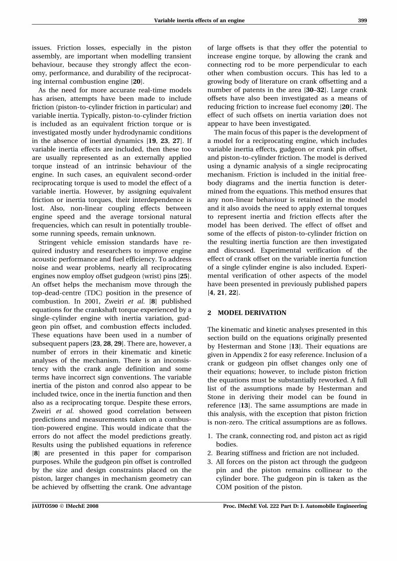
tions for a range of offset values are given in Fig. 3.
Zero on the abscissa corresponds to crank TDC.
Figure 3(a) shows the inertia function for the case of
zero offset, using equation (42) and the correspond-
ing expression from the work of Zweiri et al. [8]. The
inertia function with zero offset is expected to be
symmetrical about bottom dead centre (BDC),
because of the symmetrical path followed by the
mechanism. It is clear from Fig. 3(a) that the
equations published in reference [8] predict an
asymmetrical function and thus are fundamentally
incorrect. The magnitudes are, however, consistent
with the model presented in this paper and the
equation predicts part of the inertia function
correctly. Figures 3(b) and (c) show the effect of a
non-zero offset. For the engine used in these
predictions, a realistic gudgeon pin offset of 1.0 mm
has a negligible impact on the inertia. Even a shift of
10 mm introduces a relatively small change. Although
a 10 mm offset in gudgeon pin position is
unrealistic for the engine considered, it would be
possible to achieve this by offsetting the crank.
Figure 3(c) shows the inertia function for a positive
offset, with reference to Fig. 1, and Fig. 3(d) shows
the result for a negative offset of the same
magnitude. The COM positions of a reciprocating
mechanism, with zero and positive offset, are
shown in Fig. 1(c) at two crank locations. It can
be seen that the mechanism geometry is different
when an offset is included for each crank angle. For
CCW rotation the connecting rod and piston
positions on the mechanism with a positive offset
are more advanced than the mechanism with zero
offset. This behaviour will produce an inertia
function that leads the zero-offset case. A negative
offset will produce the opposite effect. This lead–lag
behaviour is evident in Figs 3(c) and (d). To explain
this further, the relative contributions of the piston,
connecting rod, and crank to the inertia function
need to be evaluated. To do this, equation (42) may
be rewritten in component form as
I hð Þ~IC hð ÞzIR1 hð ÞzIR2 hð ÞzIP hð Þ ð16Þ
where
IC hð Þ~ICzmCh2r2~constant ð17Þ
IR1 hð Þ~IRr cos h
l cos w
� �2
ð18Þ
IR2 hð Þ~mRr2 1{jð Þ2cos2 hz j cos h tan w{sin hð Þ2h i
~jmRr2 cos h tan w{sin hð Þ2
z 1{jð ÞmRr2 1{j cos2 h
cos2 w
� �ð19Þ
IP hð Þ~mPr2 cos h tan w{sin hð Þ2 ð20Þ
Figure 4 shows the connecting-rod and piston
inertia functions over one crank revolution. Two
cases are considered: zero offset, and a positive
offset of 10 mm. The contribution to system inertia
from the connecting rod’s mass moment of inertia
IR1(h) is illustrated in Fig. 4(a). The connecting rod
experiences significant rotation when the connect-
ing rod and crank are collinear and little rotation
Variable inertia effects of an engine 403
JAUTO590 F IMechE 2008 Proc. IMechE Vol. 222 Part D: J. Automobile Engineering
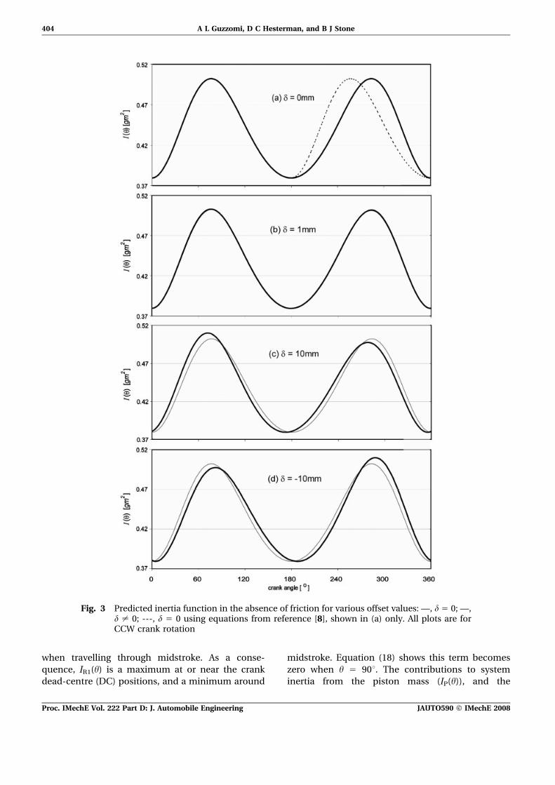
when travelling through midstroke. As a conse-
quence, IR1(h) is a maximum at or near the crank
dead-centre (DC) positions, and a minimum around
midstroke. Equation (18) shows this term becomes
zero when h 5 90u. The contributions to system
inertia from the piston mass (IP(h)), and the
Fig. 3 Predicted inertia function in the absence of friction for various offset values: —, d 5 0; —,d ? 0; ---, d 5 0 using equations from reference [8], shown in (a) only. All plots are forCCW crank rotation
404 A L Guzzomi, D C Hesterman, and B J Stone
Proc. IMechE Vol. 222 Part D: J. Automobile Engineering JAUTO590 F IMechE 2008
connecting-rod mass, (IR2(h)) are shown in Figs 4(b)
and (c) respectively. They follow an opposite trend to
IR1(h). The reciprocating mass (piston and part of the
connecting rod) experiences very little motion
around the DC positions and, thus, does not
contribute much mass loading or inertia to the
system at these locations. Around midstroke, how-
ever, the piston experiences significant motion for a
small change in crank angle and the reciprocating
inertia increases. The maximum piston inertia
occurs when the crank and connecting rod are
essentially perpendicular to each other. Equation
Fig. 4 Piston and connecting-rod inertia components: —, d 5 0; —, d 5 10 mm. All plots are forCCW crank rotation with no friction
Variable inertia effects of an engine 405
JAUTO590 F IMechE 2008 Proc. IMechE Vol. 222 Part D: J. Automobile Engineering

(19) identifies how much of the connecting-rod mass
reciprocates with the piston and how much rotates
with the crank. The ratio is controlled by the
parameter j. When j 5 0, the COM of the connecting
rod coincides with the main bearing at A and all the
connecting-rod mass rotates with the crank.
Equation (19) reduces to the inertia about O of a
lumped mass at A. When j 5 1, the COM of the
connecting rod is located at the gudgeon pin B and
all the connecting-rod mass reciprocates with the
piston. In this case, equation (19) has the same form
as equation (20). Figure 4(d) allows the relative
contribution of each inertia term to be evaluated. It
can be seen that the maximum amplitude of IR1(h) is
a tenth of that of the effective piston inertia for the
engine considered in this paper. IR1(h) is ignored in
simplified models of engines. The differences ob-
served between the inertia function of a mechanism
with zero offset and one with a non-zero offset are
due to the relationship between h and w (see
equation (2)). The largest change occurs in the
effective piston inertia IP(h) shown in Fig. 4(c). The
asymmetry in the piston and connecting-rod inertia
functions is introduced by the cos h tan w – sin h
expression in equations (19) and (20). Figure 5
shows the effect of offset on this expression.
The rotation direction of the crankshaft will
modify the effect of an offset, and this is illustrated
in Fig. 6. The results in Fig. 6(a) are for a mechanism
rotating CCW with a positive offset of 10 mm. Those
in Fig. 6(b) are for clockwise (CW) rotation with a
negative offset of 10 mm. As expected, the prediction
in Fig. 6(a) is simply a reflection of that shown in
Fig. 6(b). Inertia predictions using the equations
published in reference [8] are also given. The
prediction for the case in Fig. 6(a) is a reasonable
match for most of the cycle and agrees with the
shape published in reference [8]. Errors in the
equations are exacerbated for the case in Fig. 6(b).
In summary, typical values of gudgeon pin offset
have a negligible effect on the inertia function of an
engine. In such cases the offset can be ignored. For
large crank offsets, however, the effect is more
pronounced with observable changes in the magni-
tude and phase of the inertia function. Similar
results are observed in the functions for I9(h) and
g(h). These modified functions will influence engine
behaviour and thus their inclusion in engine models
will improve real-time prediction accuracy. These
changes may also hold significant implications for
the non-linear frequency coupling associated with
variable-inertia systems. It is noted that the effects of
any offset will increase with an increase in piston
and connecting-rod mass.
3.2 Piston friction
A theoretical investigation of how piston friction
affects the inertia function is presented in
this section. Equations (10) to (15) are used for
Fig. 5 Effect of an offset of d 5 10 mm on cos h tan w 2 sin h
Fig. 6 The effect of offset and crankshaft rotation direction with no friction for (a) d 5 210 mmand CW rotation and (b) d 5 10 mm and CCW rotation: —, d 5 0; —, d ? 0; ---, d ? 0 usingequations from reference [8]
406 A L Guzzomi, D C Hesterman, and B J Stone
Proc. IMechE Vol. 222 Part D: J. Automobile Engineering JAUTO590 F IMechE 2008

predictions. Only the zero-offset case is studied.
Typical friction values measured on a small motored
single-cylinder engine are used. Details of how these
values were obtained can be found in reference [4]. A
magnitude of 40 N is used for the ring friction Fr, and
the dynamic coefficient m of friction is taken as 0.3.
Although this friction coefficient value is large for
periods when high lubricant entrainment can be
expected (midstroke), higher values may be experi-
enced when the piston is near TDC or BDC (piston
velocity very low). In practice, the coefficient
changes throughout the engine cycle [4–6, 33–37].
However, it is not the purpose of this paper to
perform a detailed friction analysis, but rather to
show the mathematical relationship which gives rise
to the interaction. The effects of dynamic friction
increase as m increases, and a value of 0.3 allows its
influence to be clearly observed. The results pre-
sented are for a constant engine speed of 44 rad/s
(276 r/min). At this speed, ring friction dominates
system behaviour. At high engine speeds the dy-
namic friction term mS becomes significant and the
behaviour of the system changes [4]. Thus, the
results shown in Fig. 7 are valid for low speeds.
Figure 7 shows the effect of piston friction on the
different torque components of equation (10). The
‘apparent’ inertia function, predicted from equation
(11), is given in Fig. 7(a). Friction does not change
the inertia value at the DC positions when d 5 0,
because E(m) is equal to one at these positions. This
will not be the case when an offset is introduced; a
small phase shift is expected. Friction does have
a noticeable effect around midstroke, with the
‘apparent’ inertia increasing. As expected, the ‘ap-
parent’ average inertia of the mechanism increases
and more energy is required to drive the system
when friction is included. It is noted that the value
used for m in the predictions is larger than would be
expected for standard midstroke lubrication and
loading conditions. Therefore the relative change in
inertia will usually be less than that shown in
Fig. 7(a). The effect of piston friction on the
‘apparent’ rate of change in inertia is illustrated in
Fig. 7(b). The result is predicted using equation (12).
Comparing the graphs in Fig. 7(a) with those in
Fig. 7(b), it is evident that I 0f hð Þ follows the expected
shape of the true derivative of If(h). The gravity and
loading torque terms are shown in Figs 7(c) and (d),
respectively. Equations (13) and (14) are used for the
predictions. The inclusion of piston friction reduces
the gravity torque during the first half of the cycle,
when gravity assists motion and increases the torque
during the second half, when gravity opposes
motion. In the absence of pressure forces on the
Fig. 7 Crankshaft torque components: —, |Fr| 5 m 5 0; — |Fr| 5 40 N, m 5 0.3. All plots are forCCW crank rotation at 44 rad/s with d 5 0
Variable inertia effects of an engine 407
JAUTO590 F IMechE 2008 Proc. IMechE Vol. 222 Part D: J. Automobile Engineering
piston, only Fr appears in equation (14) and this term
goes to zero when friction is ignored. As expected, it
can be seen that a large torque resists motion when
ring friction is included. A more detailed discussion
of this torque, including how speed and friction
magnitudes affect its behaviour, has been given in
reference [4].
4 EXPERIMENTAL VERIFICATION
This section presents the experimental work con-
ducted to verify the effect of offset on an engine’s
inertia function. Guzzomi et al. [22] have already
reported an experimental investigation of piston-to-
cylinder friction and its effect on engine inertia.
Results from that study confirm model predictions
and show that piston-to-cylinder friction does
increase the ‘apparent’ inertia during midstroke
travel.
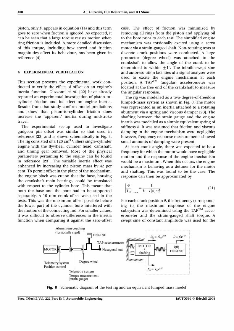
The experimental set-up used to investigate
gudgeon pin offset was similar to that used in
reference [23] and is shown schematically in Fig. 8.
The rig consisted of a 120 cm3 Villiers single-cylinder
engine with the flywheel, cylinder head, camshaft,
and timing gear removed. Most of the physical
parameters pertaining to the engine can be found
in reference [23]. The variable inertia effect was
enhanced by increasing the piston mass by 42 per
cent. To permit offset in the plane of the mechanism,
the engine block was cut so that the base, housing
the crankshaft main bearings, could be translated
with respect to the cylinder bore. This meant that
both the base and the bore had to be supported
separately. A 10 mm crank offset was used in the
tests. This was the maximum offset possible before
the lower part of the cylinder bore interfered with
the motion of the connecting rod. For smaller values,
it was difficult to observe differences in the inertia
function when comparing it against the zero-offset
case. The effect of friction was minimized by
removing all rings from the piston and applying oil
to the bore prior to each test. The simplified engine
mechanism was torsionally excited using a servo
motor via a strain-gauged shaft. Non-rotating tests at
discrete crank positions were conducted. A large
protractor (degree wheel) was attached to the
crankshaft to allow the angle of the crank to be
determined to within ¡1u. The inbuilt swept sine
and autoresolution facilities of a signal analyser were
used to excite the engine mechanism at each
position. A TAPTM (angular) accelerometer was
located at the free end of the crankshaft to measure
the angular response.
The rig was modelled as a two-degree-of-freedom
lumped-mass system as shown in Fig. 8. The motor
was represented as an inertia attached to a rotating
abutment via a spring and viscous damper [23]. The
shafting between the strain gauge and the engine
inertia was modelled as a simple equivalent spring of
stiffness k. It was assumed that friction and viscous
damping in the engine mechanism were negligible;
however, frequency response measurements showed
small amounts of damping were present.
At each crank angle, there was expected to be a
frequency for which the motor would have negligible
motion and the response of the engine mechanism
would be a maximum. When this occurs, the engine
mechanism is behaving as a detuner for the motor
and shafting. This was found to be the case. The
response can then be approximated by
H
Tm
max
~1
k{I hð Þv2n
ð21Þ
For each crank position h, the frequency correspond-
ing to the maximum response of the engine
subsystem was determined using the TAPTM accel-
erometer and the strain-gauged shaft torque. A
swept sine of constant amplitude was used for the
Fig. 8 Schematic diagram of the test rig and an equivalent lumped mass model
408 A L Guzzomi, D C Hesterman, and B J Stone
Proc. IMechE Vol. 222 Part D: J. Automobile Engineering JAUTO590 F IMechE 2008

excitation. The acceleration and torque measure-
ments were then used in equation (21) to estimate
the engine inertia. The complex geometry of the
shafting made it difficult to calculate an equivalent
stiffness analytically; hence, a constant value for k
was also estimated from the measurements. This
was found to be in reasonable agreement with a
value calculated using the geometry. Inertia values
were determined for a range of discrete crank angles
using this method and the results are shown in
Fig. 9. Model predictions using equation (2) and the
equations in Appendix 2 are also shown for the cases
of zero offset and an offset of 10 mm. It can be seen
that the prediction with offset is in very good
agreement with the ‘measured’ inertia results, both
displaying the same phase lags and amplitude
modulations. As mentioned earlier, small amounts
of damping were observed in the measured fre-
quency response functions. However, this was not
enough to change the estimated inertia values
significantly. Discrepancies between the ‘measured’
and predicted inertia functions are most probably
due to errors in the system parameters used in the
model, and the simplistic model used for the inertia
estimates.
5 CONCLUSION
This paper has presented a mathematical model for
a single reciprocating mechanism that includes a
variable mass moment of inertia, a crank or gudgeon
pin offset, and piston-to-cylinder friction. The model
extends the work reported in reference [13]. It does
not approximate friction or inertia as externally
applied torques but includes them in the model
derivation. The model was used to investigate the
effects of offset and piston friction on the inertia
function of a single mechanism, and experimental
work was reported that verifies model predictions for
a small single-cylinder engine. The main findings are
summarized below.
The inclusion of a crank or gudgeon pin offset
in the model was straightforward, with only
one equation changing from those published in
reference [13]. More significant changes to the
model were required to include piston-to-cylinder
friction. The kinetic analysis revealed that the piston
side force S is a function of any vertical loading on
the piston; hence, S is a function of piston-to-
cylinder friction. This means that the side force and
the frictional force are interdependent. The relation-
ship between these two terms is dictated by the
geometry of the reciprocating mechanism. As a
result, it is insufficient simply to ‘add’ an equivalent
friction torque into the mechanism’s torque equa-
tion when including the effects of piston friction.
The torque equation must be determined from the
original component equations of motion. When this
is carried out, the coefficient of dynamic friction
appears in a number of the torque terms, including
the ‘apparent’ inertia function of the mechanism
and the ‘apparent’ rate of change in inertia.
The model was then used to investigate the effects
of offset on the inertia function of a single recipro-
cating mechanism, with no friction present. The
inertia predictions were consistent with expecta-
tions, and a previously published model [8] was
shown to contain errors. Results from the model
presented here indicate that, for typical values, the
gudgeon pin offset does not have a significant affect
on the inertia function. However, for the larger
values used in crank offsets, the inclusion of the
offset in the engine model improves the prediction
accuracy. Large crank offsets introduce a noticeable
phase change and amplitude asymmetry in the
Fig. 9 Measured and predicted inertia functions: —, prediction with d 5 0; — prediction with d5 10 mm; O, measured with d 5 10 mm
Variable inertia effects of an engine 409
JAUTO590 F IMechE 2008 Proc. IMechE Vol. 222 Part D: J. Automobile Engineering

inertia function. Experimental work on a small
single-cylinder engine confirmed model predictions.
Previous work by the present authors has shown
that piston-to-cylinder friction must be included in
engine models, especially those used for real-time
applications. At low speeds, dynamic friction plays a
very small part and piston-to-cylinder friction can be
modelled as ring friction only. At high speeds, the
effect of dynamic friction becomes significant and
should also be included. In this paper, the effect of
piston friction on the ‘apparent’ inertia function was
investigated. Results for the case of zero offset
showed that the inclusion of friction has negligible
effect at TDC and BDC, but it increases the ‘apparent’
inertia around midstroke. This has been verified
experimentally in reference [22]. One outcome of this
behaviour is that the ‘apparent’ average inertia of the
engine increases; however, it should be noted that a
relatively large value for the dynamic coefficient of
friction was used in the predictions and only a very
small change in average inertia was determined.
The study presented in this paper has been restricted
to the effects of offset and piston-to-cylinder friction on
an engine’s variable inertia function. However, the
model can be used to study the general behaviour of
both single-cylinder and multi-cylinder engines. Equa-
tion (10) allows variable inertia, offset, and piston-to-
cylinder friction to be included in the expression for the
crankshaft torque. More recently the present authors
have used the model to investigate the non-linear
behaviour of reciprocating engines. Preliminary results
show that changes in the phase and the amplitude of
the frequency content of the inertia function will affect
frequency coupling in an engine. The relationship
between dynamic friction and the inertia function has
also been shown to influence this behaviour. It is the
intention of the present authors to present these
findings in a future paper.
ACKNOWLEDGEMENTS
The authors would like to acknowledge the financialassistance to Dr A. L. Guzzomi from the WilliamLambden Owen Scholarship fund and the RobertMaude Gledden Scholarship fund during his PhDcandidature. The completion of this paper wasperformed while Dr Guzzomi was a University ofWestern Australia Whitfeld Fellow conducting re-search at the University of Bologna.
REFERENCES
1 Schumacher, T., Biermann, J.-W., Jansz, N.,Willey, J., and Kupper, K. Load change reactions
of passenger cars: method of investigation andimprovement. Proc. Instn Mech. Engrs, Part K: J.Multi-body Dynamics, 2003, 217(4), 283–291.
2 Boysal, A. and Rahnejat, H. Torsional vibrationanalysis of a multi-body single cylinder internalcombustion engine model. Appl. Mathl Modelling,1997, 21(8), 481–493.
3 Farshidianfar, A., Ebrahimi, M., Rahnejat, H.,Menday, M., and Moavenian, M. Optimization ofthe high-frequency torsional vibration of vehicledriveline systems using genetic algorithms. Proc.Instn Mech. Engrs, Part K: J. Multi-body Dynamics,2002, 216, 249–262.
4 Guzzomi, A. L., Hesterman, D. C., and Stone, B. J.The effect of piston friction on engine blockdynamics. Proc. IMechE, Part K: J. Multi-bodyDynamics, 2006, 221(2), 277–289.
5 Mufti, R. A., Priest, M., and Chittenden, R. J.Experimental and theoretical study of instanta-neous piston assembly friction in a gasolineengine. In Proceedings of the 2004 ASME/STLEInternational Joint Tribology Conference, LongBeach, California, USA, October 2004, pp. 907–921.
6 Mistry, K., Bhatt, D. V., and Sheth, N. R.Theoretical modeling and simulation of piston ringassembly of an IC engine. In Proceedings of the2004 ASME/STLE International Joint TribologyConference, Long Beach, California, USA, October2004.
7 Richardson, D. E. Review of power cylinder frictionfor diesel engines. Trans. ASME, J. Engng GasTurbines Power, 2000, 122(4), 506–519.
8 Zweiri, Y. H., Whidborne, J. F., and Seneviratne, L.D. Detailed analytical model of a single-cylinderdiesel engine in the crank angle domain. Proc. InstnMech. Engrs, Part D: J. Automobile Engineering,2001, 215(11), 1197–1216.
9 Hesterman, D. C. and Stone, B. J. Secondaryinertia effects in the torsional vibration of recipro-cating engines – a literature review. Proc. InstnMech. Engrs, Part C: J. Mechanical EngineeringScience, 1995, 209(1), 11–15.
10 Hesterman, D. C. and Stone, B. J. A comparison ofsecondary inertia effects in a range of reciprocatingengines. In Proceedings of the International Me-chanical Engineering Congress, Canberra, Australia,1994, pp. 1–6.
11 Hesterman, D. C., Drew, S. J., and Stone, B. J.Vibration of engines resulting from torsionalvibration of crankshafts. In Proceedings of theConference on Vibrations in rotating machinery,1996, vol. 1, pp. 713–723 (Mechanical EngineeringPublications Limited, London).
12 Rajendran, S. and Narasimhan, M. V. Effect ofinertia variation due to reciprocating parts andconnecting rod on coupled vibration of crankshaft.Trans. ASME, J. Engng Gas Turbines Power, 1997,119(1), 257–264.
13 Hesterman, D. C. and Stone, B. J. A systemsapproach to the torsional vibration of multi-cylinder reciprocating engines and pumps. Proc.
410 A L Guzzomi, D C Hesterman, and B J Stone
Proc. IMechE Vol. 222 Part D: J. Automobile Engineering JAUTO590 F IMechE 2008

Instn Mech. Engrs, Part C: J. Mechanical Engineer-ing Science, 1994, 208(6), 395–408.
14 Hesterman, D. C. Torsional vibrations in recipro-cating pumps and engines. PhD Thesis, Depart-ment of Mechanical Engineering, University ofWestern Australia, Perth, Western Australia, 1992,p. 178.
15 Guzzomi, A. L., Hesterman, D. C., and Stone, B. J.Torsional vibration of engines. In Proceedings ofthe 12th International Conference on Sound andVibration, Lisbon, Portugal, July 2005, pp. 1–8.
16 Brusa, E., Delprete, C., and Genta, G. Torsionalvibration of crankshafts: effects of non-constantmoments of inertia. J. Sound Vibr., 1997, 205(2),135–150.
17 Pasricha, M. S. Effect of damping on parametri-cally excited torsional vibrations of reciprocatingengines including gas forces. J. Ship Res., 2006,50(2), 147–157.
18 Schiffer, W. Advanced methods for static anddynamic shafting calculations. J. Nav. ArchitectureShipbldg Industry (Brodogradnja), 2007, 58(2),158–164.
19 Rahnejat, H. Multi-body dynamics, 1998, p. 355(Professional Engineering Publishing Limited, BurySt Edmunds).
20 Zweiri, Y. H., Whidborne, J. F., and Seneviratne, L.D. Dynamic simulation of a single-cylinder dieselengine including dynamometer modelling andfriction. Proc. Instn Mech. Engrs, Part D: J. Auto-mobile Engineering, 1999, 213(4), 391–402.
21 Drew, S. J., Hesterman, D. C., and Stone, B. J.Torsional excitation of variable inertia effects in areciprocating engine. Mech. Systems Signal Proces-sing, 1999, 13(1), 125–144.
22 Guzzomi, A. L., Hesterman, D. C., and Stone, B. J.The effect of piston friction on the torsional naturalfrequency of a reciprocating engine. Mechl SystemsSignal Processing, 2007, 21(7), 2833–2837.
23 Zweiri, Y. H., Whidborne, J. F., and Seneviratne, L.D. A comparison of dynamic models of variouscomplexity for diesel engines. Mathl Computermodelling Dynamical Systems, 2002, 8(3), 273–289.
24 Wong, V., Tian, T., Moughon, L., Takata, R., andJocsak, J. Low-engine-friction technology for ad-vanced natural-gas reciprocating engines. AnnualTechnical Progress Report, Massachesetts Instituteof Technology, Cambridge, Massachesetts, 30 June2006.
25 Balakrishnan, S. and Rahnejat, H. Isothermaltransient analysis of piston skirt-to-cylinder wallcontacts under combined axial, lateral and tiltingmotion. J. Physics D: Appl. Physics, 2005, 38(5), 787–799.
26 Betz, G., Gabele, H., and Assmus, H.-O. Frictionpower and noise behaviour of the piston assembly.In Proceedings of the Second International Con-ference on Combustion Engines – Reduction ofFriction and Wear, London, September 1989, pp.35–58.
27 Ma, Z.-D. and Perkins, N. C. An efficient multibodydynamics model for internal combustion engine
systems. Multibody System Dynamics, 2003, 10(4),363–391.
28 Zweiri, Y. H. Diesel engine indicated torqueestimation based on artificial neural networks.Int. J. Intell. Technol., 2006, 1(3), 233–239.
29 Zweiri, Y. H. and Seneviratne, L. D. Dieselengine indicated and load torque estimation usinga non-linear observer. Proc. IMechE, Part D: J.Automobile Engineering, 2006, 220(6), 775–785.
30 Garvin, E. A. Offset crankshaft mechanism for aninternal combustion engine. US Pat. 5816201, 1998.
31 Lee, C. L. Offset crankshaft engine. US Pat.6058901, 2000.
32 Nystrom, R. Device for converting a linear move-ment into a rotary movement. US Pat. 6851401,2005.
33 Priest, M., Dowson, D., and Taylor, C. M.Theoretical modelling of cavitation in piston ringlubrication. Proc. Instn Mech. Engrs, Part C: J.Mechanical Engineering Science, 2000, 214,435–447.
34 Xu, H., Bryant, M. D., Matthews, R. D., Kiehne, T.M., and Steenwyk, B. D. Friction predictions forpiston ring–cylinder liner lubrication. In Proceed-ings of the 2004 Fall Technical Conference of theASME Internal Combustion Engine Division, LongBeach, California, USA, 2004, pp. 773–784 (Amer-ican Society of Mechanical Engineers, New York).
35 Thring, R. H. Piston skirt friction in internalcombustion engines. ASME Paper S7-1CE-20, 1987.
36 Smith, E. H., Clark, C. A., and Sherrington, I. Themeasurement of piston assembly friction in amotored engine. IMechE Conference on Universaland Poly Research on IC Engines, 1991, pp.185–190.
37 Sherrington, I. and Smith, E. H. The measurementof piston/piston-ring friction by the ‘floating –liner’method. In Proceedings of the IMechE Seminar onEngine research and development, 1988, pp. 1–11(Mechanical Engineering Publications Limited,London).
APPENDIX 1
Notation
a acceleration vector
A big-end (connecting-rod) bearing
position
B gudgeon pin position
C centre-of-mass position of the crank
COM centre of mass
D(m), E(m) convenient groupings of terms
FA big-end (connection-rod) reaction
FB gudgeon pin reaction
Fr frictional force produced by piston
ring static tension
g acceleration due to gravity
Variable inertia effects of an engine 411
JAUTO590 F IMechE 2008 Proc. IMechE Vol. 222 Part D: J. Automobile Engineering

g(h) gravity torque about O without pis-
ton-to-cylinder friction
gf(h) gravity torque about O with piston-
to-cylinder friction included
h ratio of the length OC to the length
OA (0,h,l)
I(h) inertia function of the reciprocating
mechanism without friction
I9(h) rate of change in the inertia function
with respect to the crank angle
IC inertia of crank about its centre of
mass
IC(h) constant inertia of the crank
If(h) ‘apparent’ inertia function of the re-
ciprocating mechanism with friction
I 0f hð Þ ‘apparent’ rate of change in theinertia function with friction
Ip(h) piston inertia contribution due to its
mass
IR inertia of the connecting rod about
its centre of mass
IR1(h) connection-rod inertia contribution
due to its inertia
IR2(h) connecting-rod inertia contribution
due to its mass
j ratio of the length AR to the length
AB (0,j,l)
k equivalent torsional stiffness
l length of the connecting rod 5 AB
mC mass of the crank
mP mass of the piston
mR mass of the connecting rod
O main crank bearing
PL generic pressure loading on the pis-
ton along the cylinder axis
Q(t) piston loading along the cylinder axis
Q(t,h) torque about O due to Q(t)
r crank throw 5 OA
R centre-of-mass position of the con-
necting rod
S piston side force
T crank torque
z piston displacement 5 OB
d gudgeon offset from the crank bear-
ing parallel to the cylinder bore
h angular displacement of the crank
(relative to the block)
m kinetic coefficient of friction
w angular displacement of the connect-
ing rod (relative to the cylinder bore)
vn natural frequency
APPENDIX 2
Hesterman and Stone [13] presented a dynamic
analysis of a vertically mounted single reciprocating
mechanism without crank or gudgeon pin offset.
They assumed that the mechanism was frictionless
and that there was a generic piston loading force Q(t)
acting on the crown of the piston. The main
equations describing their model are summarized
below.
Kinematic analysis
With reference to Fig. 1 with offset d 5 0,
l sin w~r sin h ð22Þ
Differentiating gives
_ww~r _hh cos h
l cos wð23Þ
€ww~ _hh2 r cos h
l cos w
� �2
tan w{r sin h
l cos w
" #z€hh
r cos h
l cos wð24Þ
Relative velocity and acceleration analyses were
performed in reference [13] to determine the COM
accelerations of the piston, connecting rod, and
crank. Equations (23) and (24) were then used in
these expressions to replace w and w respectively.
Differentiation of the geometry relationships yields
the same results. For the piston,
aPX ~0 ð25Þ
aPY ~ _hh2 r cos hð Þ2
l cos3 w{r cos h{r sin h tan w
!
z€hh r cos h tan w{r sin hð Þ ð26Þ
For the connecting rod,
aRX ~ _hh2 1{jð Þr sin h{€hh 1{jð Þr cos h ð27Þ
aRY ~ _hh2 jr cos hð Þ2
l cos3 w{r cos h{jr sin h tan w
" #
z€hh jr cos h tan w{r sin hð Þ ð28Þ
For the crank,
412 A L Guzzomi, D C Hesterman, and B J Stone
Proc. IMechE Vol. 222 Part D: J. Automobile Engineering JAUTO590 F IMechE 2008

aCX ~{ _hh2hr sin hz€hhhr cos h ð29Þ
aCY ~ _hh2hr cos hz€hhhr sin h ð30Þ
Kinetic analysis
The free-body diagrams used in reference [13] are
shown in Fig. 2, with the appropriate piston diagram
on the left of Fig. 2(a). All forces on the piston are
assumed to act through the gudgeon pin. The
dynamic equations for the piston, connecting rod,
and crank are then as follows. For the piston,
XFX~mpapX ~0
FBX {S~0
FBX ~Sð31Þ
FBY {mpg{Q tð Þ~mpapY ð32Þ
For the connecting rod,
XFX~mRaRX
FAX {FBX ~mRaRX
ð33Þ
XFY ~mRaRY
FAY {FBY {mRg~mRaRY
ð34Þ
XMR~IR
€wwR
{FBX 1{jð Þl cos w{FBY 1{jð Þl sin w
{FAX jl cos w{FAY jl sin w~IR€wwR
ð35Þ
For the crank,
XFX~mCaCX
FOX {FAX ~mCaCX
ð36Þ
XFY ~mCaCY
FOY {FAY {mCg~mCaCY
ð37Þ
XMC~IC
€hhC
TzFAX 1zhð Þr cos hzFAY 1zhð Þr sin h
{FOX hr cos h{FOY hr sin h~IC€hhC
ð38Þ
An expression for the piston side force S can be
obtained by combining equations (31) to (34) with
equation (35), and then substituting for the COM
accelerations using equations (25) to (28), according to
S~{r€hhIR cos h
l cos wð Þ2zmP tan w cos h tan w{sin hð Þ
"
zjmRj cos h
cos2 w{sin h tan w{cos h
� ��
{r _hh2 IR
l cos wð Þ2r cos2 h tan w
l cos w{sin h
� �"
zmP tan wr cos2 h
l cos3 w{sin h tan w{cos h
� �
zjmRjr cos2 h tan w
l cos3 w{cos h tan wzsin h{
j sin h
cos2 w
� ��
{g tan w mPzjmRð Þ{Q tð Þtan w ð39Þ
An expression for the crankshaft torque can beobtained by rearranging equation (38) and substitut-ing for the bearing forces to give
T~IC€hhzmCaCX hr cos h{mRaRX r cos h
zmCaCY hr sin h{mRaRY r sin h{mPaPY r sin h
zmChgr sin h{mRgr sin h{mPgr sin h
{Q tð Þr sin h{Sr cos h ð40Þ
Substituting for the COM accelerations and groupinglike terms result in
T~€hhI hð Þz 1
2_hh2I 0 hð Þzg hð ÞzQ t, hð Þ ð41Þ
where I(h) is the mechanism’s inertia function given by
I hð Þ~ICzmCh2r2zIRr cos h
l cos w
� �2
zmPr2 cos h tan w{sin hð Þ2
zmRr2 1{jð Þ2cos2 hz j cos h tan w{sin hð Þ2h i
ð42ÞI9(h) is the rate of change in inertia with respect tothe crank angle h and is given by
Variable inertia effects of an engine 413
JAUTO590 F IMechE 2008 Proc. IMechE Vol. 222 Part D: J. Automobile Engineering

I 0 hð Þ~2IRr cos h
I cos w
� �2r cos h
l cos wtan w{tan h
� �
z2mPr2 cos h tan w{sin hð Þ
r cos2 h
l cos3 w{cos h{sin h tan w
� �
{2mRr2 1{jð Þ2sin h cos h
z2mRr2 j cos h tan w{sin hð Þ
jr cos2 h
l cos3 w{cos h{j sin h tan w
� �ð43Þ
g(h) is the gravity torque given by
g hð Þ~gr mP cos h tan w{sin hð Þ½
zmR j cos h tan w{sin hð ÞzmCh sin h� ð44Þ
and Q(t, h) is the torque produced by the generalpiston loading term Q(t) acting on the piston crownand is given by
Q t, hð Þ~Q tð Þr cos h tan w{sin hð Þ ð45Þ
414 A L Guzzomi, D C Hesterman, and B J Stone
Proc. IMechE Vol. 222 Part D: J. Automobile Engineering JAUTO590 F IMechE 2008

Reproduced with permission of the copyright owner. Further reproduction prohibited without permission.