validation of a mechanical hazard fault tree for interventions in printing press danger zones
TRANSCRIPT

Studies and Research Projects
REPORT R-778
Laurent GiraudSabrina Jocelyn
Barthélemy AucourtSerge Massé
Renaud Daigle
Validation of a Mechanical Hazard Fault Treefor Interventions in Printing Press Danger Zones
Mechanical and Physical Risk Prevention

The Institut de recherche Robert-Sauvé en santé et en sécurité du travail (IRSST), established in Québec since 1980, is a scientific research organization well-known for the quality of its work and the expertise of its personnel.
MissionTo contribute, through research, to the preventionof industrial accidents and occupational diseases and to the rehabilitation of affected workers;
To disseminate knowledge and serve as a scientificreference centre and expert;
To provide the laboratory services and expertise required to support the public occupational healthand safety network.
Funded by the Commission de la santé et de la sécuritédu travail, the IRSST has a board of directors made upof an equal number of employer and worker representatives.
To find out moreVisit our Web site for complete up-to-date informationabout the IRSST. All our publicationscan be downloaded at no charge.www.irsst.qc.ca
To obtain the latest information on the research carriedout or funded by the IRSST, subscribe to Prévention autravail, the free magazine published jointly by theIRSST and the CSST.Subscription: www.csst.qc.ca/AbonnementPAT
Legal DepositBibliothèque et Archives nationales du Québec2013ISBN: 978-2-89631-672-4 (PDF)ISSN: 0820-8395
IRSST – Communications and KnowledgeTransfer Division505 De Maisonneuve Blvd. West Montréal, QuébecH3A 3C2Phone: 514 288-1551Fax: 514 [email protected]© Institut de recherche Robert-Sauvéen santé et en sécurité du travail,May 2013
OUR RESEARCHis working for you !
A PDF version of this publication is available on the IRSST Web site.
Studies andResearch Projects
Validation of a Mechanical Hazard Fault Tree for Interventions in Printing Press Danger Zones
Mechanical and Physical Risk Prevention
This study was funded by the IRSST. The conclusions and recommendations are solely those of the authors.This publication is a translation of the French original; only the original version (R-671) is authoritative.
REPORT R-778
Disclaimer
The IRSST makes no guarantee as to the accuracy, reliability or completeness of the information in this document. Under no circumstances may the IRSST be held liable for any physical or psychological injury or material damage resulting from the use of this information.
Document content is protected by Canadian intellectual property legislation.
Laurent Giraud and Sabrina Jocelyn Mechanical and Physical Risk Prevention, IRSST
Barthélemy AucourtÉCAM
Serge MasséConsultant
Renaud DaigleIRSST

In compliance with IRSST policy, the research resultspublished in this document have been peer-reviewed.
PEER REVIEW

IRSST - Validation of a Mechanical Hazard Fault Tree for Interventions in Printing Press Danger Zones i
ACKNOWLEDGEMENTS The research team would like to thank ASP imprimerie for making the visits to the printing plants a reality and for having contributed to the advancement of the project in general. We mainly thank Thierry Tollis, prevention advisor at this ASP, who was very much involved in contacting the printing plant representatives to plan the visits. His contribution was greatly appreciated, for arranging the visits as well as for his participation in project-related meetings and his availability for answering the team's questions. We also thank the ASP's general manager, Marie Ménard, and the other prevention advisors, namely Catherine Woods, Dany Mailloux and Tommy Lupien, for their help in this project. Some of these individuals accompanied us during our visits; others made themselves available for the fault tree validation meetings. Finally, we thank all the printing companies, including Au Point Reprotech and Transcontinental Litho Acmé, who gave us the opportunity to visit their premises. Thank you to the personnel of these companies who devoted several hours of their valuable time to answering our questions and sharing their work experiences with us. This proved beneficial in improving the fault tree. Finally, we thank Damien Burlet-Vienney, research assistant in machine safety at the IRSST, for his collaboration, at the start of the project, in the development of the fault tree. The authors also thank the IRSST for its financial support for this study.

IRSST - Validation of a Mechanical Hazard Fault Tree for Interventions in Printing Press Danger Zones iii
SUMMARY In 2006, a survey of the safest common practices relating to interventions on printing presses was carried out by the Association paritaire de santé et de sécurité du travail secteur imprimerie et activités connexes (ASP imprimerie, joint occupational health and safety association, printing and related activities sector), to establish a safe work procedure for these machines which include several danger zones. From this survey, the ASP developed a fault tree tracing the combinations of causes leading to crushing of a body part of a worker in a printing press nip point. As a result, this study focuses on the crushing risks related to these machines' nip points. From this fault tree, ASP imprimerie developed a method for assessing the risks associated with operations on these presses. This methodology was tested during visits to approximately 25 companies in the industry and proved to be conclusive. Prompted by this positive result, ASP imprimerie submitted a request for expertise to the IRSST's research team to validate the logic and thoroughness of the fault tree so that the ASP could subsequently disseminate it, with a methodology for risk assessment and safe procedures relating to the execution of the four following operations:
1. Roller and blanket cleaning and washing, 2. Plate insertion and removal, 3. Blanket insertion and removal, 4. Paper threading.
The purpose of this study was for the IRSST team to validate the logic and thoroughness of the initial fault tree. This validation was carried out according to the following methodology:
1. Literature search to obtain more information on the concept of fault tree, on printing presses, on the four operations studied, as well as on the standards and regulations in force relating to printing presses;
2. Field validation: visits to eight printing presses to better understand the relative danger of the nip points that the operator has to deal with during the four operations;
3. Completion and correction of the ASP fault tree, and verification of its structure in order to make corrections to it;
4. Validation of the corrected fault tree with ASP imprimerie. Application of this methodology led to the result of the study, namely a final fault tree with 300 combined causes, occupying 10 levels, and that can explain the crushing of a body part of a worker by one or more printing press rollers/cylinders during an operation. This fault tree is a useful tool. On the one hand, it makes it possible to visualize the causes and consequently to find solutions in order to avoid this crushing during an operation. The effectiveness of the solutions will depend on the category of the causes on which action will be taken. On the other hand, while this fault tree is not directly transposable to other machines with nip points and for which the causes of crushing in a nip point should be studied, it remains a very good starting model and could be adapted with a minimum of effort.


IRSST - Validation of a Mechanical Hazard Fault Tree for Interventions in Printing Press Danger Zones v
TABLE OF CONTENTS 1. INTRODUCTION ...................................................................................................... 1
1.1 Background/origin of the project .................................................................................... 1
1.2 OHS problem ..................................................................................................................... 1
1.3 Why are safe procedures needed? ................................................................................... 2
1.4 Objectives and limitations of the project ........................................................................ 3
2. LITERATURE SEARCH .......................................................................................... 5
2.1 Fault tree ............................................................................................................................ 5
2.1.1 Definition and usefulness of a fault tree ......................................................................... 5
2.1.2 The original FT proposed by ASP imprimerie ............................................................... 7
2.2 Printing presses and their hazards .................................................................................. 8
2.2.1 Sheet-fed presses ............................................................................................................. 8
2.2.2 Rotary presses ................................................................................................................. 9
2.2.3 Definition of a nip point ................................................................................................ 10
2.3 Current regulations and standards ............................................................................... 11
2.3.1 The ROHS ..................................................................................................................... 11
2.3.2 Standards ....................................................................................................................... 13
3. METHODOLOGY ................................................................................................... 15
3.1 Methodology used ........................................................................................................... 15
3.2 Validation of the FT with ASP imprimerie .................................................................... 16
4. FIELD VISITS ........................................................................................................ 17
4.1 Visit procedure ................................................................................................................ 17
4.2 Information collected during the visits ......................................................................... 17
4.2.1 Danger zones and corresponding tasks ......................................................................... 17
4.2.2 Machine start-up ........................................................................................................... 20
4.2.3 Means of risk reduction ................................................................................................ 23
4.2.4 Work organization: possible difficulties ....................................................................... 29
4.2.5 The observed operations ............................................................................................... 32
4.3 General observations from the visits ............................................................................. 34
5. MAIN EVOLUTIONS IN THE FT ............................................................................ 37
5.1 Analysis of the format of the initial FT ......................................................................... 37
5.2 Analysis of the content of the FT ................................................................................... 39

vi Validation of a Mechanical Hazard Fault Tree for Interventions in Printing Press Danger Zones - IRSST
5.3 Subsequent evolutions of the FT .................................................................................... 39
5.3.1 Evolution #1 .................................................................................................................. 39
5.4 Evolution #2 ..................................................................................................................... 40
5.4.1 Evolution #3 .................................................................................................................. 41
5.4.2 Evolution #4 .................................................................................................................. 42
5.4.3 Evolution #5 .................................................................................................................. 43
5.4.4 Evolution #6 .................................................................................................................. 44
6. RESULTS .............................................................................................................. 47
6.1 The final FT ..................................................................................................................... 47
6.1.1 Top of the FT ................................................................................................................ 48
6.1.2 Sub-system "A": hazard ................................................................................................ 49
6.1.3 Sub-system "B": voluntary access ................................................................................ 49
6.1.4 Sub-system "C″: involuntary access ............................................................................. 49
6.1.5 Sub-system "D": impossibility of avoidance ................................................................ 50
6.2 Final FT: discussion and limitations ............................................................................. 50
6.3 Possibility of analysis of the final FT ............................................................................ 50
6.3.1 Concept of "defense in depth" ...................................................................................... 50
6.3.2 Analysis......................................................................................................................... 51
7. CONCLUSION AND DISCUSSION ....................................................................... 55
8. REFERENCES....................................................................................................... 57
APPENDIX 1: INITIAL FAULT TREE ........................................................................... 60
APPENDIX 2: ACCIDENT PROCESS AND COMPOSITION OF RISK [35] ................ 65
APPENDIX 3: FINAL FAULT TREE ............................................................................. 66
APPENDIX 4: MEETINGS WITH ASP IMPRIMERIE ................................................... 82
First meeting ............................................................................................................................. 82
Second meeting ......................................................................................................................... 82
Third meeting ............................................................................................................................ 83
Fourth meeting .......................................................................................................................... 83

IRSST - Validation of a Mechanical Hazard Fault Tree for Interventions in Printing Press Danger Zones vii
LIST OF TABLES
Table 1: General symbols used in an FT ................................................................... 6
Table 2: Transfer symbols used in an FT .................................................................. 6
Table 3: Gate symbols used in an FT ........................................................................ 7
Table 4: Nip points – Possible configurations ......................................................... 11
Table 5: Standards consulted to develop the FT ...................................................... 14
Table 6: Actual visits ............................................................................................... 16
Table 7: Hazards – Rotating rollers or cylinders forming a nip point ..................... 18
Table 8: Hazards - Blade .......................................................................................... 18
Table 9: Hazards – A moving component getting close to a fixed component ....... 19
Table 10: Hazards – Gravity (a worker falling from a height) ................................ 19
Table 11: Hazards – Gravity (a worker falling at the same level) ........................... 19
Table 12: Standardized modes of control of slow speed ......................................... 21
Table 13: Use of the terms jog and inch according to the sources .......................... 22
Table 14: Legend for the FT .................................................................................... 47


IRSST - Validation of a Mechanical Hazard Fault Tree for Interventions in Printing Press Danger Zones ix
LIST OF FIGURES
Figure 1: Roller and cylinder configuration in a printing press unit ....................... 10
Figure 2: Safeguards against nip points ................................................................... 24
Figure 3: Appearance of the safe control mode button (or safe ready) ................... 26
Figure 4: Insertion of a plate .................................................................................... 32
Figure 5: End of paper stuck (in the circle) on a blanket ......................................... 34
Figure 6: Example of modification of the fault tree so that it verifies the form criteria .................................................................................................. 38
Figure 7: Example of modification of the fault tree so that it corresponds to the form criteria ......................................................................................... 38
Figure 8: 1st version of the top of the fault tree........................................................ 40
Figure 9: 2nd version of the top of the fault tree ....................................................... 41
Figure 10: 3rd version of the top of the fault tree ..................................................... 42
Figure 11: 4th version of the top of the fault tree ..................................................... 43
Figure 12: 5th version of the top of the fault tree ..................................................... 43
Figure 13: 6th version of the top of the fault tree ..................................................... 45
Figure 14: Abridged FT ........................................................................................... 48


IRSST - Validation of a Mechanical Hazard Fault Tree for Interventions in Printing Press Danger Zones 1
1. INTRODUCTION
1.1 Background/origin of the project
In 2006, a survey of the safest common practices, mainly relating to the washing of printing press cylinders and blankets, was carried out by the Association paritaire de santé et de sécurité du travail secteur imprimerie et activités connexes (ASP imprimerie), for the purpose of establishing a safe work procedure for these machines. From this survey, the ASP developed a fault tree (FT) tracing the combinations of causes resulting in the crushing of a body part of a worker in a printing press nip point during these operations: cleaning and washing of rollers and blankets, changing (insertion and removal) of plates. Based on this FT, the ASP then developed a method for assessing the risks related to the above-mentioned operations. Tested during visits to approximately 25 companies in the industry, this methodology proved conclusive and a few deficiencies in the FT were identified. Prompted by this positive result, ASP imprimerie submitted a request for expertise to the IRSST research team in 2007 to validate the logic and thoroughness of the FT so that the ASP could disseminate it to its members with a methodology for evaluating the risks and safe procedures for performing these tasks. The ASP also asked the research team to include the paper feeding/threading operation, to comment on the corrections made to the fault tree, and to include references to the regulations and standards in force (particularly those relating to the printing industry). 1.2 OHS problem
A synthesis of the injuries compensated by the CSST1 in the printing industry for the year 2006 indicates that 118 accidents occurred directly on the machines2 and that 8 others were caused by falls due to possible unevenness between the ground and these machines. These 118 accidents cost the CSST $786,586 and represented 7663 lost days in 2008, while this study was being carried out. The 8 others totalled $25,252 and 244 lost days in 2008. This study, the response to the request from ASP imprimerie for expertise, is therefore of interest: in responding to this request, the IRSST provided clarifications for the different causes of failure comprising the successive levels in the fault tree. This fault tree will result in a reduction in the accidents related to printing presses by making workers in the printing industry aware, during training, of the dangers caused by these machines. These clarifications involve causes of failures not mentioned in the initial FT, standards and regulations prescribing safety measures, or any other correction or comment ensuring clarity of the information conveyed in the fault tree.
This study focused on common practices, related to work in the printing industry, during which operators are exposed to hazards during the four following operations:
• cleaning and washing of rollers and blankets, • changing (insertion and removal) of plates, • changing (insertion and removal) of blankets,
1 Statistical production by the CSST for ASP Imprimerie, reference year 2006, produced in 2008. 2 Accidents on printing presses have been investigated in recent years by the CSST: report EN-003662 (2006), [15,
16].

2 Validation of a Mechanical Hazard Fault Tree for Interventions in Printing Press Danger Zones - IRSST
• feeding/threading of paper.3 These four operations expose the operator mainly to the following hazard: rotating rollers and cylinders forming nip points. In fact, during these operations, the operators perform interventions near or in the nip points. Unfortunately, as the ASP mentioned to the research team, the performance of these four tasks requires the rotation of the machine's rollers and cylinders. Québec OHS regulations advocate numerous solutions for preventing accidents, including machine lockout. However, in this case, according to the ASP (this point will be discussed in greater detail later in the report), the use of lockout procedures is not the most appropriate means for managing the crushing risk. The developed FT will therefore, following this study, identify the aspects where action should be taken in order to propose safe generic procedures for the performance of these four operations. 1.3 Why are safe procedures needed?
In the framework of the four above-mentioned operations, developing safe work methods other than lockout is important in order to comply with the Regulation respecting occupational health and safety (ROHS) because:
• Lockout is not appropriate for the performance of these operations because roller and cylinder rotation, and therefore operation of the machine, is required at different moments in order to carry out these tasks. Consequently, section 185 of the ROHS cannot be applied;
• Except for automatic roller washing (control option on some presses4), there are still no intrinsic technical solutions (eliminating the hazard) that can ensure the operators' safety during these interventions;5
• A means must be found to ensure the workers' safety when performing one of these four operations in which they often have to remove a guard (section 184 of the ROHS, requiring the installation of guards, is not applicable).
The section that pertains to the present situation is section 186 of the ROHS6 [25]. However, these methods can only apply to printing presses already safeguarded with guards and/or protective devices so that they comply with this section:
Section 186. Adjustment, repair, unjamming, maintenance and apprenticeship: When a worker must access a machine's danger zone for adjustment, unjamming, maintenance, apprenticeship or repair purposes, including for detecting abnormal operations, and to do so, he must move or remove a protector, or neutralize a protective device, the machine shall only be restarted by means of a manual control or in compliance with a safety procedure
3 The term "paper feeding" is used for sheet-fed presses, whereas the term "paper threading" is used for presses fed from a roll of paper.
4 Automatic washing greatly reduces the need for manual washing but without eliminating it completely. Manual cleaning is therefore necessary, but less often.
5 On some recent presses, plates are inserted and removed automatically, which reduces the risk. 6 Section 186 of the ROHS is basically similar to section 4.11.9 of ISO 12100-2:2003.
IRSST - Validation of a Mechanical Hazard Fault Tree for Interventions in Printing Press Danger Zones 3
specifically provided for allowing such access. This manual control or this procedure shall have the following characteristics: (1) it causes any other control mode or any other procedure, as the case may be, to become inoperative; (2) it only allows the operation of the dangerous parts of the machine by a control device requiring continuous action or a two-hand control device; (3) it only allows the operation of these dangerous parts under enhanced security conditions, for instance, at low speed, under reduced tension, step-by-step or by separate steps.
After reading section 186, it is clear that printing press danger zones must be safeguarded (ROHS, article 182) before safety measures other than lockout are applicable. This is the case on recent machines equipped with locked or interlocked movable guards. However, considering the nature of these operations, section 185 of the ROHS—which deals with lockout—is not applicable because controlled cylinder rotation is required for the operations to be carried out properly. In addition, removing the guards (ROHS, section 184) is necessary to perform four tasks. Section 186 of the ROHS therefore applies in these four cases. Consequently, in compliance with section 186, a safety procedure must be planned for each of these operations. These procedures are defined according to the principle in CSA Z460-05 (mainly section 7.2) [8], a standard that provides for alternative measures when lockout does not apply. 1.4 Objectives and limitations of the project
The aim of this project was to improve the fault tree submitted by ASP imprimerie to the IRSST, by validating its logic and its thoroughness. The corrected FT had to be accompanied by references to the standards or regulations in force. With this fault tree, mainly intended for printing press operators, it is possible to identify the different combinations of causes that can result in crushing of a part of the body. The fault tree was developed in order to identify, after this study, safe work methods during interventions near or in a nip point during the four following operations:
1. Cleaning and washing of rollers and blankets, 2. Insertion and removal of plates, 3. Threading of paper, 4. Insertion and removal of blankets.7
This project's final fault tree contains as much information as possible. The information was chosen such that the fault tree would contain a satisfactory level of detail, meaning that it would allow its user to identify appropriate solutions. Furthermore, if the user so wishes, he can always increase the content of the fault tree by identifying the reason for certain causes not developed in the last level of detail of the fault tree. The fault tree was validated according to the steps in research methodology.
7 ASP imprimerie had initially requested that the FT be developed around operations 1, 2 and 3. However, the research team decided to include operation 4 following field observation.

IRSST - Validation of a Mechanical Hazard Fault Tree for Interventions in Printing Press Danger Zones 5
2. LITERATURE SEARCH
First, a literature search was carried out to better understand the project and its context. Publications, standards, the ROHS, accident reports, scientific articles, as well as approximately a dozen reports of previous visits by ASP imprimerie were consulted. The literature search provided an understanding of printing press risks and operations and led to the first corrections to the ASP imprimerie fault tree. 2.1 Fault tree
2.1.1 Definition and usefulness of a fault tree
A fault tree is a graphical tool that traces the combinations of causes [24, 38, 40] resulting in an undesirable event (here, an accident) related to a given analyzed system. This fault tree is in the form of a logic diagram: the combinations of causes are established by means of gates (AND, OR, conditional, etc.). This logic diagram can be read inductively or deductively:
• "Inductive" reading consists of identifying different combinations of causes of failures located at the bottom in order to arrive at the final event, located at the top and caused by the former. This final event is what is called the undesirable event.
• "Deductive" reading consists of beginning with the undesirable event, the first at the top, and tracing the causes of failure, located at the bottom.
"Inductive" reading of the fault tree begins with the cause of the problem in order to arrive at its undesirable effect, whereas "deductive" reading of the fault tree starts with the undesirable effect to trace its origin. The cause-consequence relationship must therefore always be verified in the fault tree so that, during deductive or inductive reading, the logical link between the different events remains. Furthermore, in constructing the fault tree, the deductive method [24] applies, because to develop this graphical tool beginning with the undesirable event, a question must be asked at each subsequent (lower) level about what combination of causes produces the event, or the cause of the level above. The symbols involved in the construction of such a tool are presented in the three following tables (Table 1 to Table 3). A fault tree is a useful tool: it serves as a fool-proof device (safeguard) in the design and maintenance (or other operation) of a system [18]. In both cases, it plays a leading edge role. On the one hand, it informs the designer about the causes of failures generating a hazardous event, while indicating the points on which he must act in order to eliminate or reduce the risk of failure in the design of the system in question. Second, it warns the worker (operator or maintenance employee), in the execution of his tasks, about the danger zones present on the machine where he is working and about the possible causes of accidents, whether the failure is of technical, human or organizational origin. Third, the FT is used to trace the causes of an event or an accident that has already taken place. In fact, a technician who knows his printing press and the details surrounding this event or accident will be able, by going from the top of the fault tree to the bottom, to recognize the intermediate events responsible for the possible causes, and by taking

6 Validation of a Mechanical Hazard Fault Tree for Interventions in Printing Press Danger Zones - IRSST
into consideration the decision gates AND and OR, to arrive at the initial causes at the bottom of the system(s) in question.
Table 1: General symbols used in an FT GENERAL SYMBOLS:
Symbol of the undesirable event (the accident).
Symbol for an intermediate cause (or event). It is developed by subsequent causes (or events).
Conditioning symbol. It is an extension of the inhibition gate (Table 3).
Symbol for an undeveloped cause due to insufficient information, or in order to simplify the fault tree when sufficient details are known (this symbol is found in the last level presented in a branch of the fault tree).
Symbol for an initiating cause (normal event) related to an action or a normal state (e.g., a maintenance activity on the printing press).
Symbol of a basic cause (primary fault), i.e., requiring no development (this symbol is found at the last level presented in a branch of the fault tree).
Table 2: Transfer symbols used in an FT TRANSFER SYMBOLS:
Transfer to the corresponding sub-system (identified) in the fault tree. A sub-system is a part of an FT that is a group of linked causes (this simplifies the FT by avoiding repetition).
Identifies the sub-system transferred to by the previous symbol.

IRSST - Validation of a Mechanical Hazard Fault Tree for Interventions in Printing Press Danger Zones 7
Table 3: Gate symbols used in an FT GATES:
AND
Output
Input
Gate indicating that all the causes at input must exist to obtain the consequence at output.
OR
Input
Output
Gate indicating that one of the causes at input is sufficient to have the consequence at output.
Inhibit gate connected to the conditioning symbol (Table 1).
Along the same lines, corrections to the fault tree proposed by ASP imprimerie improve the working conditions of printing press operators and maintenance personnel by making them aware of the causes of crushing of one or more body parts of a worker in a printing press nip point.
Obtaining information about how a fault tree works (its reading and construction) led to a better understanding of the original ASP imprimerie fault tree (see next section) as well as to the initial corrections to its form and content (cf. sections 5.1 and 5.2).
2.1.2 The original FT proposed by ASP imprimerie
The fault tree initially8 developed by ASP imprimerie (Appendix 1) consisted of the following elements:
• Top of the tree: where the undesirable event serving as a basis for the construction of thefault tree is "Crushing between two press rollers/cylinders during an operation"(Appendix 1.1). Here, the study is limited to the risks of crushing in a nip point.According to this initial fault tree, crushing will occur only if the three followingconditions are met (AND gate): presence of a nip point, cylinders or rollers moving(sub-system "A"), and the worker accesses a danger zone (sub-system "B"). At the topof the fault tree, the presence of a nip point is explained either by no protection, or by aninadequate guard;
• Sub-system "A": "Cylinders or rollers moving " (Appendix 1.2); the cause of cylinder orroller rotation may be due to the fact that movement was initiated in controlled actionmode, or (OR gate) because it was initiated in production mode;
• "B-insertion of plates" sub-system: "Worker accesses danger zone" (Appendix 1.3);
8 Remark: For purposes of clarity, there is the top of the fault tree, and all the other fault trees are appended trees (sub-systems) which are transfers from the top of the tree or from another appended tree.
8 Validation of a Mechanical Hazard Fault Tree for Interventions in Printing Press Danger Zones - IRSST
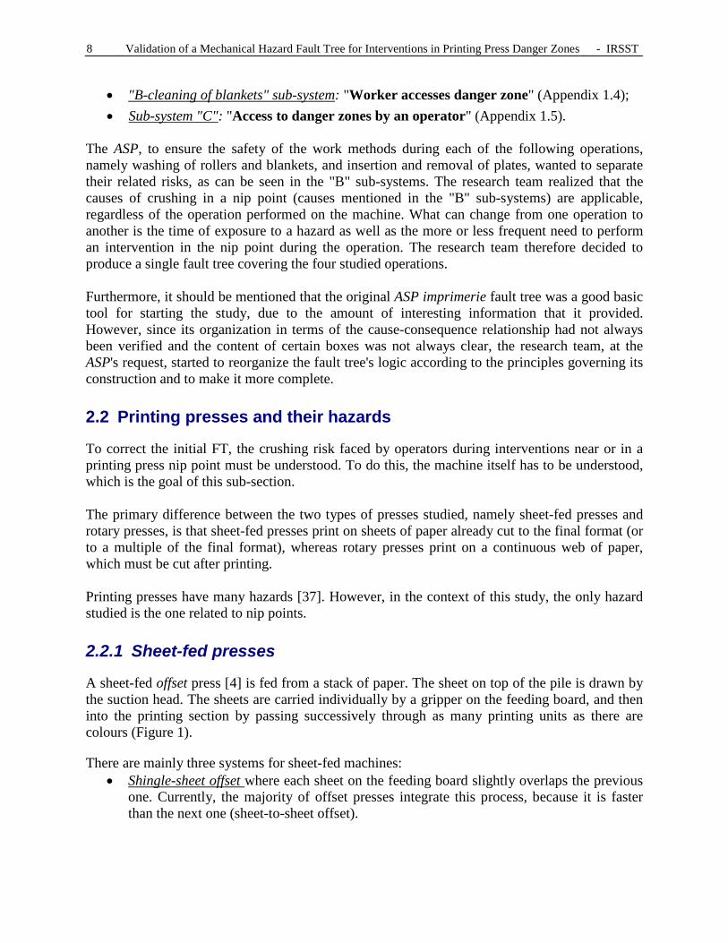
• "B-cleaning of blankets" sub-system: "Worker accesses danger zone" (Appendix 1.4); • Sub-system "C": "Access to danger zones by an operator" (Appendix 1.5).
The ASP, to ensure the safety of the work methods during each of the following operations, namely washing of rollers and blankets, and insertion and removal of plates, wanted to separate their related risks, as can be seen in the "B" sub-systems. The research team realized that the causes of crushing in a nip point (causes mentioned in the "B" sub-systems) are applicable, regardless of the operation performed on the machine. What can change from one operation to another is the time of exposure to a hazard as well as the more or less frequent need to perform an intervention in the nip point during the operation. The research team therefore decided to produce a single fault tree covering the four studied operations. Furthermore, it should be mentioned that the original ASP imprimerie fault tree was a good basic tool for starting the study, due to the amount of interesting information that it provided. However, since its organization in terms of the cause-consequence relationship had not always been verified and the content of certain boxes was not always clear, the research team, at the ASP's request, started to reorganize the fault tree's logic according to the principles governing its construction and to make it more complete. 2.2 Printing presses and their hazards
To correct the initial FT, the crushing risk faced by operators during interventions near or in a printing press nip point must be understood. To do this, the machine itself has to be understood, which is the goal of this sub-section. The primary difference between the two types of presses studied, namely sheet-fed presses and rotary presses, is that sheet-fed presses print on sheets of paper already cut to the final format (or to a multiple of the final format), whereas rotary presses print on a continuous web of paper, which must be cut after printing. Printing presses have many hazards [37]. However, in the context of this study, the only hazard studied is the one related to nip points. 2.2.1 Sheet-fed presses
A sheet-fed offset press [4] is fed from a stack of paper. The sheet on top of the pile is drawn by the suction head. The sheets are carried individually by a gripper on the feeding board, and then into the printing section by passing successively through as many printing units as there are colours (Figure 1).
There are mainly three systems for sheet-fed machines: • Shingle-sheet offset where each sheet on the feeding board slightly overlaps the previous
one. Currently, the majority of offset presses integrate this process, because it is faster than the next one (sheet-to-sheet offset).

IRSST - Validation of a Mechanical Hazard Fault Tree for Interventions in Printing Press Danger Zones 9
• Sheet-to-sheet offset where the sheets are sent one after another to the feeding board, and the sheets do not overlap. This system is generally used in small offset presses, sometimes called duplicators.
• Direct-feed offset where the sheets pass directly under the blanket cylinder without involving a feeding board.
2.2.2 Rotary presses
A rotary offset press is fed from a roll of paper, contrary to a sheet-fed press which prints directly on a sheet of precut paper. The advantage of a rotary press is its very high printing speed. A rotary press includes the following different main parts:
• Guiding system: the web of paper passes first through a series of rollers laid out in an "S", which allows the tension on the paper to be kept uniform over the entire width of the web.
• Printing units: generally, there are four printing units, for 4 colours (black, blue, yellow and red), allowing a very large variety of colour nuances. The order of the colours can vary. For example, black is generally first in North American printing companies, before cyan (blue), magenta (red), and then yellow. The order of the colours can also be influenced by the dominant colour in the document to be printed.
• Dryers: are used to dry very quickly the ink coming out of the printing units and to extract the solvents; when the paper leaves the dryer, it is at a temperature of 90–100°C.
• Chilling system: cools and prepares the paper for folding. • Cutting-folding: the folder pulls the web of paper for the entire line, and folds and cuts
the paper. The documents (newspapers, advertising, books, etc.) coming out of this unit are ready for delivery.
The paper-threading operation on this type of press is time-consuming and hazardous. In fact, the end of the paper must pass through each unit, until delivery, namely at the output of the cutting and folding unit. This means that operators access the danger zones (nip points) throughout the operation and, on large presses, must work at heights (the printing units can be located one above the other for parallel work). The majority of accidents occur during paper feeding of these presses. The folder, which cuts and folds the paper web, has danger zones due to the different blades, the chopper blade and rotating rollers. This operation must be carried out with precision; otherwise it can cause paper jamming or tearing during production.
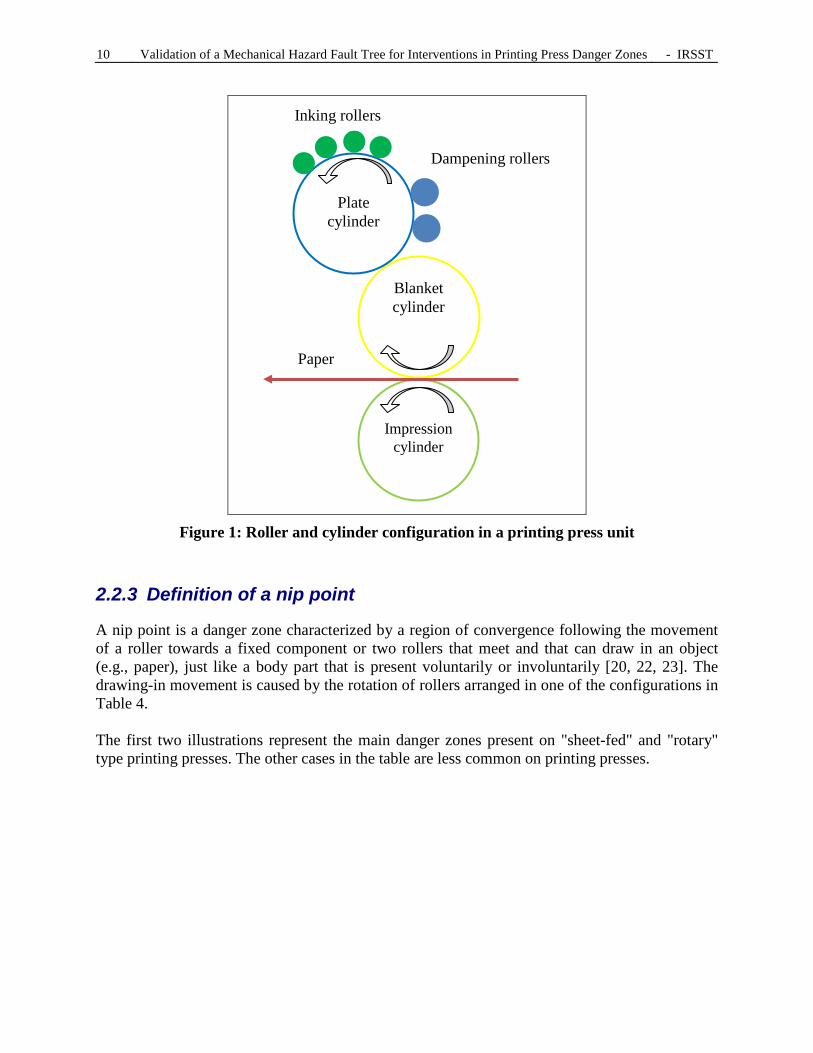
In summary, there are several danger zones on printing presses. However, in the context of the project, it was decided to focus on the zones where the most accidents occur: nip points, particularly those found between two consecutive units. The majority of the accidents occur in danger zones because they have to be accessed during normal interventions on presses: roller and blanket cleaning, plate changing, blanket changing and paper insertion. In each unit, rollers and cylinders are configured as shown in Figure 1 below. This configuration is typical of presses using the offset printing process. The paper shown in this figure is transferred to the next unit by a transfer cylinder (omitted from the figure) located to the left of the impression cylinder.
10 Validation of a Mechanical Hazard Fault Tree for Interventions in Printing Press Danger Zones - IRSST
Figure 1: Roller and cylinder configuration in a printing press unit
2.2.3 Definition of a nip point
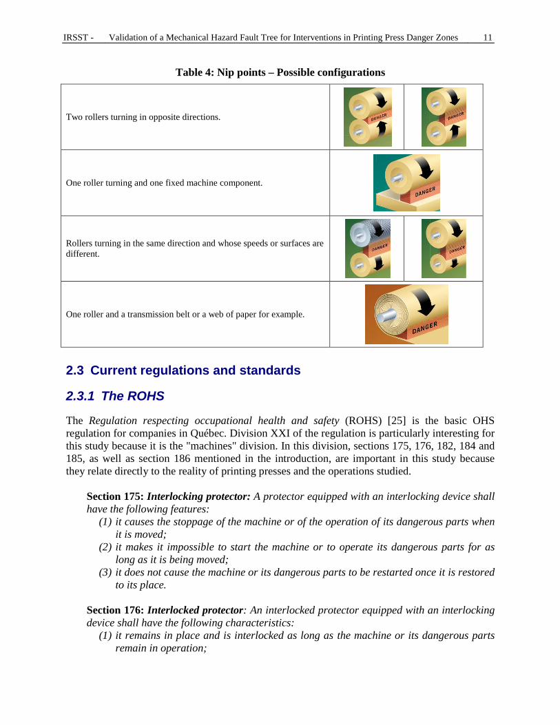
A nip point is a danger zone characterized by a region of convergence following the movement of a roller towards a fixed component or two rollers that meet and that can draw in an object (e.g., paper), just like a body part that is present voluntarily or involuntarily [20, 22, 23]. The drawing-in movement is caused by the rotation of rollers arranged in one of the configurations in Table 4. The first two illustrations represent the main danger zones present on "sheet-fed" and "rotary" type printing presses. The other cases in the table are less common on printing presses.
Blanket cylinder
Plate
cylinder
Impression
cylinder
Inking rollers
Dampening rollers
Paper
IRSST - Validation of a Mechanical Hazard Fault Tree for Interventions in Printing Press Danger Zones 11
Table 4: Nip points – Possible configurations
Two rollers turning in opposite directions.
One roller turning and one fixed machine component.
Rollers turning in the same direction and whose speeds or surfaces are different.
One roller and a transmission belt or a web of paper for example.
2.3 Current regulations and standards
2.3.1 The ROHS
The Regulation respecting occupational health and safety (ROHS) [25] is the basic OHS regulation for companies in Québec. Division XXI of the regulation is particularly interesting for this study because it is the "machines" division. In this division, sections 175, 176, 182, 184 and 185, as well as section 186 mentioned in the introduction, are important in this study because they relate directly to the reality of printing presses and the operations studied.
Section 175: Interlocking protector: A protector equipped with an interlocking device shall have the following features:
(1) it causes the stoppage of the machine or of the operation of its dangerous parts when it is moved;
(2) it makes it impossible to start the machine or to operate its dangerous parts for as long as it is being moved;
(3) it does not cause the machine or its dangerous parts to be restarted once it is restored to its place.
Section 176: Interlocked protector: An interlocked protector equipped with an interlocking device shall have the following characteristics:
(1) it remains in place and is interlocked as long as the machine or its dangerous parts remain in operation;

12 Validation of a Mechanical Hazard Fault Tree for Interventions in Printing Press Danger Zones - IRSST
(2) it makes it impossible to start the machine or to operate its dangerous parts for as long as it has not been restored to its place and reactivated;
(3) it does not cause the machine or its dangerous parts to be restarted once it is restored to its place and reactivated.
Section 182: Controlling the danger zone: Subject to section 183, a machine shall be designed and built so as to make its danger zone inaccessible, failing which it shall be equipped with at least one of the following protectors or protective devices:
(1) in the case where no one will have access to the machine's danger zone while it is in operation: (a) a permanent protector; (b) a protector fitted with an interlocking device; (c) an interlocked protector fitted with an interlocking device; (d) a sensor device;
(2) in the case where at least one person will have access to the machine's danger zone
while it is in operation: (a) a protector fitted with an interlocking device; (b) an interlocked protector fitted with an interlocking device; (c) an automatic closing protector; (d) an adjustable protector; (e) a sensor device; (f) a two-hand control.
Section 184: Installation: Subject to section 186, before operating a machine, the protectors shall be installed or the protective devices shall be operational. Section 185: Making secure: Subject to the provisions of section 186, before undertaking any maintenance, repair or unjamming work in a machine's danger zone, the following safety precautions shall be taken:
(1) turn the machine's power supply switch to the off position; (2) bring the machine to a complete stop; (3) each person exposed to danger locks off all the machine's sources of energy in order
to avoid any accidental start-up of the machine for the duration of the work. As was previously mentioned, the four operations studied require access to danger zones (normally safeguarded for production speed) as well as the initiation of movement of rollers and cylinders. It is therefore impossible to use lockout and, to access the danger zones, the guards must be removed, which leads to section 186. As mentioned in the introduction, section 186 of the ROHS applies only in the situation where the danger zone initially has a guard or a protective device, but that someone had to move, had to remove, or had to neutralize in order to access the zone to carry out one of the following tasks: adjustment, unjamming, maintenance, apprenticeship or repair. Three of the studied operations (changing of plates, blankets, and insertion of paper) are adjustment activities, and the last one (cleaning and washing of rollers and blankets) can be included as maintenance even though it is a task performed by production operators.

IRSST - Validation of a Mechanical Hazard Fault Tree for Interventions in Printing Press Danger Zones 13
2.3.2 Standards
ISO and CEN machine-related standards [11, 13, 27, 30] are classified according to three categories: type A standards, type B standards, and type C standards (going from the more general to the more specific):
• Type A standards (basic standards): contain basic safety concepts, design principles and general aspects relating to machinery;
• Type B standards (generic standards): deal with one safety aspect or one type of safeguard valid for a wide range of machinery:
• Type B1 standards deal with specific safety aspects; • Type B2 standards deal with safeguards;
• Type C standards (safety standards by category of machine): deal with detailed safety requirements applying to a particular machine or group of machines;
• When a type C standard recommends provisions deviating from those of a type A or B standard, the provisions of the type C standard take precedence over those of the other standards.
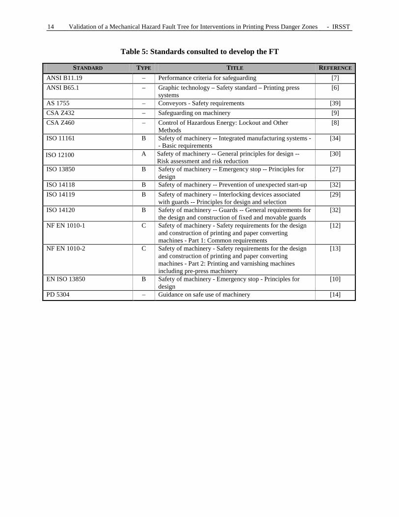
The main standards that served as references for printing press safety are those identified in Table 5. They are basically ISO or CEN standards as well as ANSI or CSA standards.
14 Validation of a Mechanical Hazard Fault Tree for Interventions in Printing Press Danger Zones - IRSST
Table 5: Standards consulted to develop the FT
STANDARD TYPE TITLE REFERENCE ANSI B11.19 – Performance criteria for safeguarding [7] ANSI B65.1 – Graphic technology – Safety standard – Printing press
systems [6]
AS 1755 – Conveyors - Safety requirements [39] CSA Z432 – Safeguarding on machinery [9] CSA Z460 – Control of Hazardous Energy: Lockout and Other
Methods [8]
ISO 11161 B
Safety of machinery -- Integrated manufacturing systems -- Basic requirements
[34]
ISO 12100
A Safety of machinery -- General principles for design -- Risk assessment and risk reduction
[30]
ISO 13850 B Safety of machinery -- Emergency stop -- Principles for design
[27]
ISO 14118 B Safety of machinery -- Prevention of unexpected start-up [32] ISO 14119 B Safety of machinery -- Interlocking devices associated
with guards -- Principles for design and selection [29]
ISO 14120 B Safety of machinery -- Guards -- General requirements for the design and construction of fixed and movable guards
[32]
NF EN 1010-1 C Safety of machinery - Safety requirements for the design and construction of printing and paper converting machines - Part 1: Common requirements
[12]
NF EN 1010-2 C Safety of machinery - Safety requirements for the design and construction of printing and paper converting machines - Part 2: Printing and varnishing machines including pre-press machinery
[13]
EN ISO 13850 B Safety of machinery - Emergency stop - Principles for design
[10]
PD 5304 – Guidance on safe use of machinery [14]

IRSST - Validation of a Mechanical Hazard Fault Tree for Interventions in Printing Press Danger Zones 15
3. METHODOLOGY
3.1 Methodology used
After studying the original FT developed by ASP imprimerie, the team proceeded to correct and validate the fault tree by applying the following methodology: 1. Literature search (see previous chapter) to:
1.1. Obtain additional information about the concept of a fault tree, 1.2. Obtain information about the composition of a printing press, its operation, and the
procedures generally applied to perform the four operations studied, 1.3. Identify the current standards and regulations applicable to printing presses;
2. Field validation, visits to eight companies with printing presses (duration: approximately three hours each), in order to better understand the risk relating to nip points faced by the operator during the four operations mentioned in Section 1.4;
3. Completion and correction of the ASP fault tree, and verification of its structure in order to make corrections to it;
4. Validation of the corrected fault tree with ASP imprimerie.
The following items specify the methodology: • The companies were selected by the research partner (ASP imprimerie), visit after visit,
in order to adapt to the printing companies' time and production constraints while taking into account the remaining observations in relation to the objectives.
• A fourth operation, blanket insertion and removal, was added. • The fault tree was corrected at the same time as the other items in the methodology were
carried out. Instead of a final validation meeting for the fault tree, there were four meetings during the study.
• Due to the various constraints, it was impossible to carry out all the planned visits. The actual visits are presented in Table 6. Field validation of the fault tree was done during the eight visits, the first for familiarization and seven others for observation. The familiarization visit was used for making contact with the printing industry and learning about printing presses, in order to have a greater understanding of the general operation (printing processes, controls for risk reduction) and to identify the hazards present during the performance of the operations. Large printing presses were more common than small ones. During these company visits, the IRSST team was always accompanied by at least one prevention advisor from ASP imprimerie, who acted as intermediary between the research team and the operators.

16 Validation of a Mechanical Hazard Fault Tree for Interventions in Printing Press Danger Zones - IRSST
Table 6: Actual visits Visit no. Type Size Technical
characteristics Year of
manufacture Operations Printed
product 0
(familiar-ization visit)
Rotary (2 levels)
large Unknown Cleaning Advertising pamphlets
1 Sheet-fed (1 level)
large Each station (unit) is moved by the main
shaft and is not disengageable
Unknown Blanket insertion and removal Plate insertion and removal Cleaning Paper feeding
Advertising and other pamphlets
2 Sheet-fed (1 level)
large ~1980 Blanket insertion and removal Plate insertion and removal Cleaning Paper feeding
Unknown
3 Rotary (1 level)
small Each station (unit) is moved individually and synchronously
with the others
2007 Blanket insertion and removal Plate insertion and removal Cleaning
Labels for wine bottles
4 Rotary (2 levels)
large Each station (unit) is moved by the main
shaft and is individually
disengageable
1982 Cleaning Paper threading
Newspapers
5 Sheet-fed (1 level)
large Two stations (units) (colours), completely
mechanical not disengageable
Between 2000 and 2001
Blanket insertion and removal Plate insertion and removal Paper feeding
Unknown
6 Sheet-fed (basically
mechanical)
small Each station (unit) is moved by the main
shaft and is not disengageable
Between 1990 and 1995
Blanket insertion and removal Plate insertion and removal Cleaning Paper feeding
Business cards
7 Rotary (2 levels)
large Each station (unit) is moved by the main
shaft and is not disengageable
1970 Paper threading Advertising and other pamphlets
3.2 Validation of the FT with ASP imprimerie
To validate the FT, the research team met with ASP imprimerie representatives on four occasions (Appendix 4): The first two meetings were with prevention advisors from this ASP; The third meeting was with Marie Ménard, the general manager of ASP imprimerie, and
with one experienced press operator (25 years) met during one of our visits; The fourth meeting was with all of the prevention advisors from this ASP.
These validation meetings, like the visits, were held to verify the logic and content of the FT, to complete it, to clarify certain points in it, and to simplify the formulation of certain causes, so that the language adopted would be subject to as little interpretation as possible and would be appropriate for all readers.

IRSST - Validation of a Mechanical Hazard Fault Tree for Interventions in Printing Press Danger Zones 17
4. FIELD VISITS
4.1 Visit procedure
Prior to the seven visits (Table 6), a familiarization visit was carried out. Its purpose was to make contact with companies with printing presses in order to understand their general operation (printing processes, control system, risk reduction strategies) as well as to rapidly identify the hazards present, mainly during task performance. The average duration of the visits was 3 hours and their format was as follows:
• Initial meeting to establish the project and visit objectives, and to sign consent forms and the authorization form for the use of photographs and videos;
• In-shop demonstration by a press operator of the method used for carrying out one or more of the four operations studied;
• Question period during the demonstrations (the people interviewed were press operators; besides the press operators, a foreman was questioned during one visit and a press operator instructor during another visit). The people met during the visits were also employer representatives and members of the health and safety committee of the printing companies;
• Meeting at the end of the visit to ask the final questions and to validate the fault tree that was evolving from one visit to the next.
During these visits, we collected our data by means of photographs, videos and questionnaires during the demonstration. Two printing companies did not allow photographs and videos to be taken. The questionnaires provided answers to the team's questions about specific aspects of the fault tree, about the machine's operation, about the control system and the safe function, as well as about the difficulties encountered by the interviewed operators in the context of their work on printing presses. From the exchanges with the workers during the visits, the fault tree was completed and some parts of it were validated. The questionnaires were improved from visit to visit based on the research team's feedback. 4.2 Information collected during the visits
The information is presented in the following order: 1. Description of the danger zones; 2. The controls for initiating start-up of the printing press; 3. The means of risk reduction (ranked according to ISO 12100:2010); 4. Work organization; 5. The observations made.
4.2.1 Danger zones and corresponding tasks
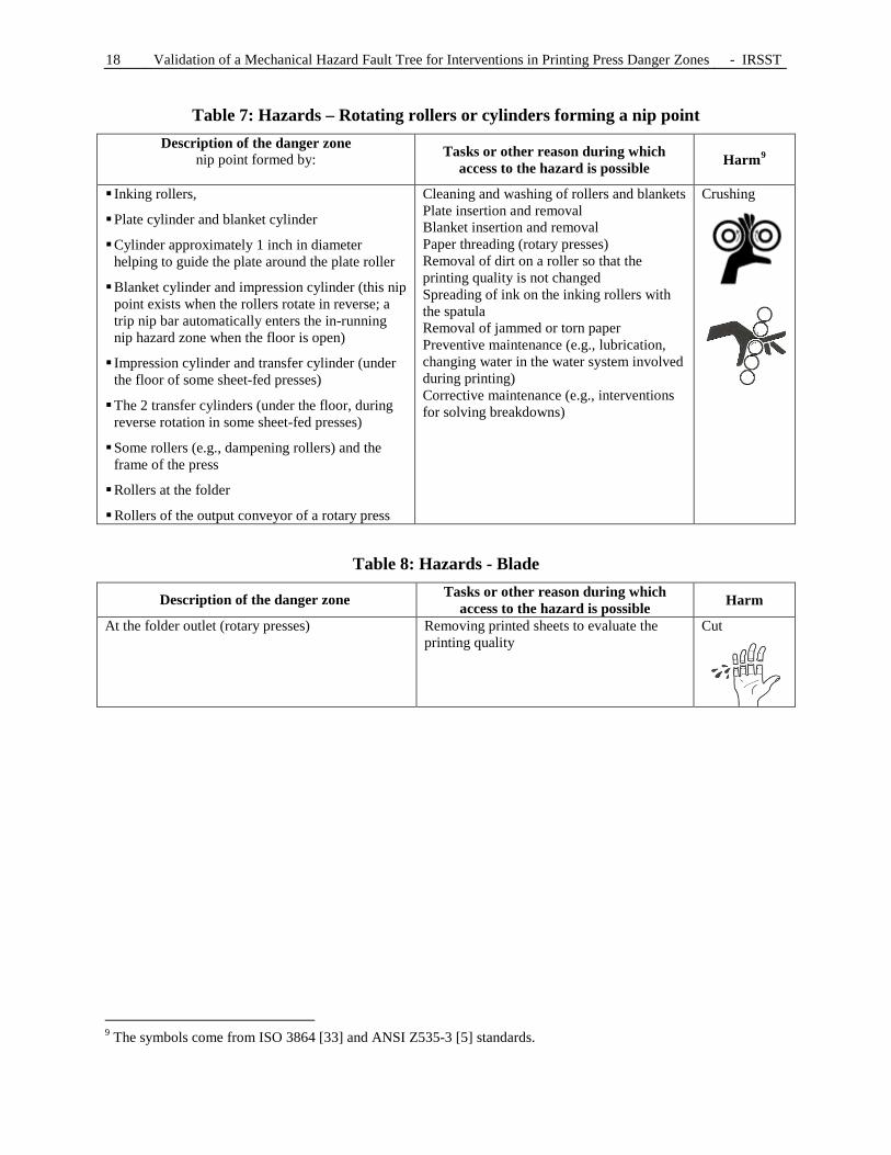
While the goal of the study was to focus on nip points, the research team also documented other danger zones present on printing presses. This information (description of the danger zone, tasks that may require access to the danger zone, possible harm) is summarized in the tables below (Table 7 to Table 11).
18 Validation of a Mechanical Hazard Fault Tree for Interventions in Printing Press Danger Zones - IRSST
Table 7: Hazards – Rotating rollers or cylinders forming a nip point Description of the danger zone
nip point formed by:
Tasks or other reason during which access to the hazard is possible Harm9
Inking rollers,
Plate cylinder and blanket cylinder
Cylinder approximately 1 inch in diameter helping to guide the plate around the plate roller
Blanket cylinder and impression cylinder (this nip point exists when the rollers rotate in reverse; a trip nip bar automatically enters the in-running nip hazard zone when the floor is open)
Impression cylinder and transfer cylinder (under the floor of some sheet-fed presses)
The 2 transfer cylinders (under the floor, during reverse rotation in some sheet-fed presses)
Some rollers (e.g., dampening rollers) and the frame of the press
Rollers at the folder
Rollers of the output conveyor of a rotary press
Cleaning and washing of rollers and blankets Plate insertion and removal Blanket insertion and removal Paper threading (rotary presses) Removal of dirt on a roller so that the printing quality is not changed Spreading of ink on the inking rollers with the spatula Removal of jammed or torn paper Preventive maintenance (e.g., lubrication, changing water in the water system involved during printing) Corrective maintenance (e.g., interventions for solving breakdowns)
Crushing
Table 8: Hazards - Blade
Description of the danger zone Tasks or other reason during which access to the hazard is possible Harm
At the folder outlet (rotary presses) Removing printed sheets to evaluate the printing quality
Cut
9 The symbols come from ISO 3864 [33] and ANSI Z535-3 [5] standards.

IRSST - Validation of a Mechanical Hazard Fault Tree for Interventions in Printing Press Danger Zones 19
Table 9: Hazards – A moving component getting close to a fixed component
Description of the danger zone Tasks or other reason during which access to the hazard is possible Harm
Gripper bars moving (e.g., at production speed) in the partially closed area where the printed sheets pile up
Movable platform at sheet input and output
Removing printed sheets to evaluate the printing quality Automatic insertion of sheets by the suction heads Sheet collection (sheet-fed presses)
Pinching Crushing Impact
Table 10: Hazards – Gravity (a worker falling from a height)
Description of the danger zone Tasks or other reason during which access to the hazard is possible Harm
Upper level of a rotary press Paper threading (rotary presses) in particular Removal of dirt from a roller so that the printing quality is not changed Removal of jammed or torn paper Maintenance
Fracture Bruise
Table 11: Hazards – Gravity (a worker falling at the same level)
Description of the danger zone Tasks or other reason during which access to the hazard is possible Harm
Uneven surfaces A worker moving on this surface Fracture Bruise
However, the fault tree deals only with the danger zone: zone of convergence created by a nip point. Access to nip points is possible if the worker goes there voluntarily or involuntarily (cf. Sub-systems "B" and "C" of the final FT, Appendix 3.2 and Appendix 3.3). At the beginning, we expected to study the risks of crushing in a nip point during paper feeding on sheet-fed and rotary presses. However, the visits showed us that this risk exists only for rotary presses, because paper is inserted automatically on a sheet-fed press by suction heads. For sheet-fed presses, the mechanism for sheet transfer from one unit to another can be considered as a danger zone. This mechanism10 is often inaccessible during production, but becomes accessible during maintenance interventions.
10 Generally transfer cylinders, but it can also take the form of a transfer prism.

20 Validation of a Mechanical Hazard Fault Tree for Interventions in Printing Press Danger Zones - IRSST
Adjustment of the operating parameters of a press does not require access to a danger zone. It is done from a control panel located outside the danger zone. Depending on the size of the press, the person controlling the press may not see the other workers accessing the machine. Mirrors are often installed close to the control panel to improve the view of the press, but blind spots remain. 4.2.2 Machine start-up
The machine can be started at slow speed (reduced speed), at production speed, as well as at a press preparation speed whose rapidity is between the two previous speeds. 4.2.2.1 Slow speed and speed controls
Slow speed can approximate 276 impressions (or complete revolutions of the blanket) per hour. Generally, slow speed is locally controlled (on each unit) from one or two local control panels. To do this, the control system of most machines requires an initial local activation of the control panel via a function called safe,11 in order to render all the other modes of control inoperative,12 and then slow speed is activated by one of the three following control modes: hold-to-run action, limited movement, or crawl speed (Table 12). The first two control modes are defined in ISO 12100:2010 [30]. The definitions given in CSA Z432-2004 [9] are equivalent, in French as well as English. The "hold-to-run" control is the one that initiates and maintains rotation of the printing press rollers and cylinders as long as the control is activated (held). The "limited movement" control initiates rotation of a predetermined fraction of a turn of the rollers and cylinders following activation13 of the control that is not necessarily hold-to-run. On all the presses except one, these two control modes were activated by pressing on a button with one hand,14 which leaves the operator's other hand free. The first two control modes, "hold-to-run" and "limited movement," allow the cylinders to turn in both directions, forward or reverse. In the case of reverse rotation, the out-running angles, which are not generally protected, become nip points. They must therefore be considered as new danger zones.
11 This safety function is defined in Section 4.2.3.4. 12 Point 1 in section 186 of the ROHS. 13 Here, the control mode used in the printing industry differs slightly from the specifications of ISO 12100-2. 14 A single printing press required the use of a two-hand control.

IRSST - Validation of a Mechanical Hazard Fault Tree for Interventions in Printing Press Danger Zones 21
Table 12: Standardized modes of control of slow speed Control mode English version Corresponding French term
Hold-to-run control device (ISO 12100-2:2003, 3.26.3): control device which initiates and maintains hazardous machine functions only as long as the manual control (actuator) is actuated
Hold-to-run control device
Action maintenue
Limited movement control device (ISO 12100-2:2003, 3.26.9): control device, a single actuation of which, together with the control system of the machine, permits only a limited amount of travel of a machine element
Limited movement control device
Par à-coups
Crawl (continuous low speed) in non-hold-to-run control mode
Crawl Vitesse lente continue
However, on some sheet-fed printers, the last control mode (crawl) does not require activation of safe to be activated. Generally, crawl mode makes the cylinders turn in only one direction: the forward direction (direction in which the cylinders rotate at production speed). 4.2.2.2 Hold-to-run, limited movement, jog and inch
The different visits to the printing companies revealed the great confusion surrounding the use of these first two control modes, in French as well as in English. In fact, during the visits, the team realized that the meaning of the English terms (jog and inch used more than the French terms) varied from one printing company to another, while the meaning of the French terms varied less. For example, for some press operators, the terms jog and inch were synonyms; for others, these terms were different. However, no press operator used the standard terms. This confusion is also found in other sources such as "Le petit Gutenberg," "Le grand Dictionnaire terminologique," the "Harrap's Shorter" and one HSC document15 (Table 13). Le petit Gutenberg,16 a collection of printing vocabulary produced by the comité sectoriel de main-d'œuvre des communications graphiques du Québec, indicates:
• Par à-coups (Jog): Action qui consiste à faire avancer ou à faire rouler les équipements de presses et de finition-reliure selon le désir de l'opérateur afin de faire les ajustements de la mise en train ou de faire une vérification. Jog: Action consisting of making the press and finishing-binding equipment advance or rotate according to what the operator wants in order to make the adjustments to press preparation or to do a verification.
There is therefore no reference either to the fact that movement is limited, or that the action on the button must be sustained, which is shown by two empty cells in Table 13.
15 Joint Standing Committee for the Wool Textile Industry, Safety in early processes (page 1), Health and Safety Commission, London, 1990.
16 Le petit Gutenberg, vocabulaire de l'imprimerie, Comité sectoriel de main-d'œuvre des communications graphiques du Québec, Montréal, 2007.

22 Validation of a Mechanical Hazard Fault Tree for Interventions in Printing Press Danger Zones - IRSST
Le grand dictionnaire terminologique17 provides two definitions of "à-coups" with a different translation:
• bouton d'avance par à-coups (synonyme(s) bouton d'avance par impulsions) – secteur imprimerie: Équivalent(s) en anglais - inch pushbutton; Printing industry: button that initiates inching, advancement by pulses. English equivalent: inch pushbutton
• bouton À-coup – chemin de fer: Bouton qui met en branle un mécanisme faisant avancer (ou reculer) une locomotive, un wagon par à-coup, lors de manœuvres, Équivalent(s) en anglais jog button. Railroad: button that starts a mechanism that advances (or reverses) a locomotive, a train car by inches, during manoeuvres. English equivalent: jog button
The "Harrap's Shorter" English-French dictionary gives the following meanings for the words jog and inch:
• jog: vt (push) pousser (d'un coup sec), (shake) secouer • inch along, inch forward: vi avancer tout doucement, vtsep (sth) faire avancer tout
doucement Finally, the HSC "Safety in early processes" document indicates in the first chapter relating to general safety principles of machines that Inching corresponds to a limited movement, opposed to jog or crawl which allow the machine to move as long as the start button is being pushed.
Table 13: Use of the terms jog and inch according to the sources Control mode Le Petit
Gutenberg Grand dictionnaire
terminologique Harrap's Shorter
Safety in early processes
Control device requiring hold-to-run Inch Jog or Crawl
Control device by limited movement Inch (printing)
Jog (railroad) Jog Inch
This shows that there is great variation in the interpretation of the two first modes of control (jog and inch) in the printing sector, and that the same terms will have a different meaning depending on the company. However, within the same company, the meaning of these two terms was identical. Crawl was the only term that had the same meaning in all the companies. For a better understanding and to avoid all confusion, we will therefore use the terminology in Table 12 in the remainder of the report. Slow speed activation is possible only from a local control panel for each printing unit. On the large sheet-fed presses observed, there were two panels per unit (one main panel and one secondary panel), while for rotary presses (large and small), there was only one panel per unit. Two control panels per unit has advantages as well as disadvantages:
• Advantage: • When the operator works alone on his unit, he has access to two panels, one to the
right and the other to the left of the work area. This makes his task easier by avoiding
17 Le grand dictionnaire terminologique: http://www.oqlf.gouv.qc.ca/ressources/gdt.html, visited in February 2010.

IRSST - Validation of a Mechanical Hazard Fault Tree for Interventions in Printing Press Danger Zones 23
him having to go to the same side of the unit to activate the control. However, the main panel has more functions than the secondary panel (for example, crawl speed is often only on the main panel);
• When two operators work together, one operator can focus on the intervention near or in the nip point, while the other can control the machine;
• The two operators have direct access to a stop button or an emergency stop button. • Disadvantage:
• When two operators work together, one of the two operators could initiate start-up of the machine, even at slow speed, while the second operator works in the nip point. This could result from an error in communication or a human error. The worker near the main panel could also possibly deactivate the safe function, thus leaving control to another person who could then start the printing press in normal mode.
The operators met during the visits indicated that slow speed, regardless of the control mode (hold-to-run or not), is generally used for interventions near or in nip points, such as:
• preventive or corrective maintenance, • insertion and removal of plates or blankets, • cleaning and washing of rollers and blankets, • paper threading (on rotary presses).
On some presses, slow speed is fixed and depends on the press manufacturer. On other presses, slow speed is adjustable from the machine's main control panel. For one press in particular, slow speed can be modified from the machine's main control panel when the machine is operating at crawl speed. Unexpected acceleration can then be an accident factor because the operator who initiated crawl speed from the unit may not be aware of the sudden change in the slow speed. 4.2.2.3 Production and press preparation speed
Production speed can be approximately 4000 to 8000 impressions (or complete revolutions) per hour. Another speed, press preparation speed, can be approximately 2500 to 3500 impressions per hour. The latter is used to adjust the press before launching production or between two productions if the machine is not to be completely stopped. Generally, a recently manufactured and safeguarded press can start at production speed only if all the guards are closed and all the safe functions are deactivated. This speed can be activated only from the main control panel of the press. 4.2.3 Means of risk reduction
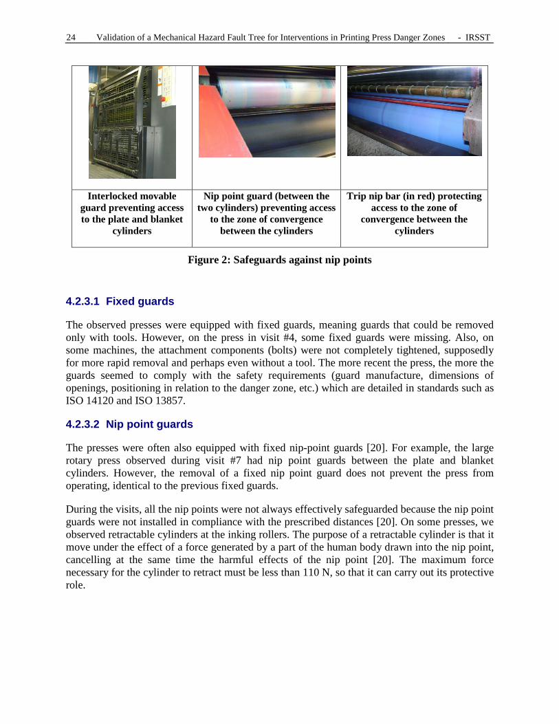
Different means of risk reduction are used on printing presses to reduce access to the danger zone. These could be fixed guards (e.g., nip point guards), movable guards generally locked out or with trip nip bars (Figure 2). The emergency stop will also be included in this section. However, many presses, particularly the oldest ones, have few means of risk reduction, with the effect being that many accesses to the various danger zones remain. This was noted during the different visits.
24 Validation of a Mechanical Hazard Fault Tree for Interventions in Printing Press Danger Zones - IRSST
Interlocked movable guard preventing access to the plate and blanket
cylinders
Nip point guard (between the two cylinders) preventing access
to the zone of convergence between the cylinders
Trip nip bar (in red) protecting access to the zone of
convergence between the cylinders
Figure 2: Safeguards against nip points
4.2.3.1 Fixed guards
The observed presses were equipped with fixed guards, meaning guards that could be removed only with tools. However, on the press in visit #4, some fixed guards were missing. Also, on some machines, the attachment components (bolts) were not completely tightened, supposedly for more rapid removal and perhaps even without a tool. The more recent the press, the more the guards seemed to comply with the safety requirements (guard manufacture, dimensions of openings, positioning in relation to the danger zone, etc.) which are detailed in standards such as ISO 14120 and ISO 13857.
4.2.3.2 Nip point guards
The presses were often also equipped with fixed nip-point guards [20]. For example, the large rotary press observed during visit #7 had nip point guards between the plate and blanket cylinders. However, the removal of a fixed nip point guard does not prevent the press from operating, identical to the previous fixed guards.
During the visits, all the nip points were not always effectively safeguarded because the nip point guards were not installed in compliance with the prescribed distances [20]. On some presses, we observed retractable cylinders at the inking rollers. The purpose of a retractable cylinder is that it move under the effect of a force generated by a part of the human body drawn into the nip point, cancelling at the same time the harmful effects of the nip point [20]. The maximum force necessary for the cylinder to retract must be less than 110 N, so that it can carry out its protective role.

IRSST - Validation of a Mechanical Hazard Fault Tree for Interventions in Printing Press Danger Zones 25
4.2.3.3 Movable guards
The majority of modern printing presses are now equipped with interlocked movable guards or interlocked movable guards with guard locking.18 Consequently, as soon as an interlocked guard is moved, the machine automatically stops. Then, depending on the machine's characteristics, the printing press could be operated at reduced speed, which will be discussed in the next section. It is in this situation that an unprotected nip point can be accessed.
The rotary presses observed during visits #4 and #7 were equipped with interlocked movable guards with guard locking at the folder. However, on one of these two printing presses, the interlocked guard with guard locking used a time delay (5 seconds) to allow access to the danger zone. The problem is that after 5 seconds, the hazard had not been eliminated. In this case, it would have been more appropriate and safer to detect non-rotation of the rotating blades as the condition for opening the interlocked guard.
Movable guards, essentially interlocked guards, which prevent access to the nip points, were identified in the following zones:
• In front of the plate, blanket, impression, and transfer cylinders (transfer cylinders were present in the floor of all the large sheet-fed presses visited);
• In front of the inking rollers; • Above the inking rollers.
On the sheet-fed presses observed during the visits, when a movable guard on a unit was open, an indicator light on the main control panel indicated this situation, and start-up of the machine from the main panel was no longer authorized. This therefore fulfilled conditions #1 and #2 of section 175 of the ROHS, or condition #2 of section 176 of the ROHS. Opening of the majority of the interlocked guards initiated the immediate stopping of the machine, even at production speed.19 However, this ideal situation did not exist on all of the machines. Indeed, on the majority of the observed sheet-fed and rotary presses, the inking rollers above each unit were protected by a movable guard without a safety device. In reality, opening of the guard did not cause the machine to stop. A single press, the one in visit #4, was equipped with an interlocked movable guard in front of the inking rollers, a guard that fulfilled the three conditions in section 175.
The press in visit #7 also had a few deficiencies with respect to movable guards. All of its movable guards were not necessarily instrumented, which allowed the machine to operate with the guards open or closed. In fact, one of the movable guards on the small sheet-fed press observed during visit #6 had been bypassed. The switch on the guard was kept depressed with adhesive tape to simulate closing of the guard and allow the machine to operate all the time, whether the guard was closed or open, thus allowing access to the initially safeguarded danger zones.
18 According to the meaning in the EN or ISO standards [20]. 19 All the systems intended to stop or keep the press stopped must be reliable in order to ensure the safety of the
people performing interventions on the machines, and are hence the responsibility of the integrators and designers of these machines [26].
26 Validation of a Mechanical Hazard Fault Tree for Interventions in Printing Press Danger Zones - IRSST
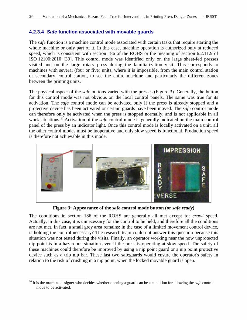
4.2.3.4 Safe function associated with movable guards
The safe function is a machine control mode associated with certain tasks that require starting the whole machine or only part of it. In this case, machine operation is authorized only at reduced speed, which is consistent with section 186 of the ROHS or the meaning of section 6.2.11.9 of ISO 12100:2010 [30]. This control mode was identified only on the large sheet-fed presses visited and on the large rotary press during the familiarization visit. This corresponds to machines with several (four or five) units, where it is impossible, from the main control station or secondary control station, to see the entire machine and particularly the different zones between the printing units.
The physical aspect of the safe buttons varied with the presses (Figure 3). Generally, the button for this control mode was not obvious on the local control panels. The same was true for its activation. The safe control mode can be activated only if the press is already stopped and a protective device has been activated or certain guards have been moved. The safe control mode can therefore only be activated when the press is stopped normally, and is not applicable in all work situations.20 Activation of the safe control mode is generally indicated on the main control panel of the press by an indicator light. Once this control mode is locally activated on a unit, all the other control modes must be inoperative and only slow speed is functional. Production speed is therefore not achievable in this mode.
Figure 3: Appearance of the safe control mode button (or safe ready)
The conditions in section 186 of the ROHS are generally all met except for crawl speed. Actually, in this case, it is unnecessary for the control to be held, and therefore all the conditions are not met. In fact, a small grey area remains: in the case of a limited movement control device, is holding the control necessary? The research team could not answer this question because this situation was not tested during the visits. Finally, an operator working near the now unprotected nip point is in a hazardous situation even if the press is operating at slow speed. The safety of these machines could therefore be improved by using a nip point guard or a nip point protective device such as a trip nip bar. These last two safeguards would ensure the operator's safety in relation to the risk of crushing in a nip point, when the locked movable guard is open.
20 It is the machine designer who decides whether opening a guard can be a condition for allowing the safe control mode to be activated.

IRSST - Validation of a Mechanical Hazard Fault Tree for Interventions in Printing Press Danger Zones 27
On the large sheet-fed presses visited, the safe control mode was present on each unit. The local slow speed controls can be activated only from the unit where the safe function has already been activated. If the safe function is deactivated while the press is operating at slow speed, the press stops. Also, if a guard on another unit is moved, the machine stops.
On the large rotary press, during the familiarization visit, and contrary to the large sheet-fed presses, once the safe control mode has been activated, start-up at slow speed is authorized from a three-position control knob (stop, go, emergency stop). This three-position control device is normally used in robotics. Slight pressure must be maintained on the knob for it to remain in the intermediate position that authorizes start-up. Once the knob is released or tightened, it activates the normal stop (release) or the emergency stop (tightening). However, once the emergency stop has been activated, the machine must be restarted.
The small sheet-fed press in visit #6 was the only sheet-fed press visited that did not have a safe control mode. However, it had a simple stop button for the mechanical system. Once this button stops the mechanism, the press is locked in order to allow the machine to start, but at reduced speed only. Slow speed on this small sheet-fed press is allowed only in hold-to-run mode, by pressing on one of the two buttons provided for this: one for forward movement, and the other for reverse movement. Considering the size of the machine, the operator has total control over all the danger zones of the machine from the single control panel.
This concept of safe control mode leads to a discussion about dependence and independence between the printing units, with respect to motor power and control. In fact, all the presses visited, except for the small rotary press in visit #3, have mechanically dependent printing units. This means that one or two main motors mechanically drive all the units and that it is physically impossible to have only one unit turn while the others are stopped. However, depending on the configuration of the press, it may be possible to disengage the units mechanically when the press is stopped. But this possibility is mainly reserved for stopping a single unit while the others are operating, rather than the opposite (all the units except one are stopped). In fact, if one unit is started at reduced speed, so will the other units.
As for dependence with respect to control, a safety-related deficiency was observed for the older sheet-fed presses visited. There was no local indicator on the safe activation units. This means that if two workers on two different units initiate the safe control mode at the same time, only the worker who initiated the safe function first will be protected, since the second does not have control priority. In the case of recent printing presses, if a guard is opened on another unit, the press stops, which is safe. For older and less safeguarded presses, this situation is more critical because danger zones are accessible and the second worker is then in a hazardous situation. In this case, only the first operator will have control over his working area because start-up of the press cannot be initiated by controls outside this unit.
Only one press did not have this configuration. In fact, for the small rotary press in visit #3, no mechanical link existed between the units because they were all driven by a dedicated servo-actuator for each unit. The only dependence between the units was control, which was centralized. However, when a movable guard on one unit was opened, the units became independent from each other regarding control. This ensures the safety of the workers working

28 Validation of a Mechanical Hazard Fault Tree for Interventions in Printing Press Danger Zones - IRSST
simultaneously on different units, because each operator controls the activation of his unit at slow speed (the only mode that can be activated when a guard is opened).
4.2.3.5 Trip nip bar
A trip nip bar is a safety device that stops the press when pressure is applied on it. This device is mentioned in many standards in the printing sector [12]. During the visits, trip nip bars were essentially seen on the large sheet-fed presses in the nip points created by:
• The zone of convergence between the plate cylinder and the blanket cylinder; • The zone of convergence between the blanket cylinder and the impression cylinder.
The use of trip nip bars varied from one press to another. It is a less common device than movable guards. A trip nip bar well-positioned in the nip point prevents crushing of part of the worker's body during tasks such as blanket or plate insertion and removal, where the worker performs an intervention on the rollers, very close to the nip point's zone of convergence. Moreover, these trip nip bars can also safeguard an out-going nip which is then not safeguarded by a fixed or movable guard. Stopping is initiated by pressure on the bar, only if the machine is operating in reverse, because the out-running nip then becomes a nip point.
However, to be effective, they must be well positioned, which did not always seem to be the case. On one of the presses, the space between the trip nip bar and the roller was large enough for fingers to access the nip point without touching the bar.
4.2.3.6 Emergency stop
The emergency stop must prevent impending hazardous situations from occurring. The hazardous process must be stopped as quickly as possible without creating other hazards and by introducing a safeguarding movement [27, 30]. In section 192, the ROHS mentions that "any machine whose operation requires the presence of at least one worker shall be equipped with an emergency stopping device or switch […]."
All of the observed presses but one had an emergency stop. The only press without one was the small sheet-fed press observed during visit #6 (it only had simple stop buttons). Of the eight visited presses, only the small rotary press observed during visit #3 had a pull-cord emergency stop. This red cord ran along the base of the press and was easily accessible.
The presses (six out of eight) with emergency stop buttons had at least one emergency stop button on each of their units. Seven presses out of the eight also had an emergency stop button, mushroom-shaped on a yellow background, located on the main control panel.
The emergency stop buttons were essentially located near the rollers and cylinders of each unit, near the folder and on the main control panel. Despite the availability of the emergency stop button on each unit, it can be difficult and even impossible for the operator to reach, depending on his work position and the size of the unit. This situation was seen mainly on the large rotary or sheet-fed presses.
Operators that were met who worked on one large rotary press mentioned to the research team that the company's operating procedures required that the emergency stop button be used as a

IRSST - Validation of a Mechanical Hazard Fault Tree for Interventions in Printing Press Danger Zones 29
means of safeguarding their tasks. In fact, once the emergency stop is activated, the press cannot be operated, either from another unit or from the main control panel. However, to minimize time losses, they preferred using verbal coordination between operators rather than activating the emergency stop button before each intervention in a danger zone, even when they know that this practice makes an unexpected start-up of the press possible.21 In this case, safety is based only on verbal communication between operators, because it is impossible for them to see each other due to the size and layout of the different units.
4.2.3.7 Sound signal
All the observed presses except one (a small one) had a sound signal for warning the operators about the imminent start-up of the machine [12]. This signal sounds before each start-up of the machine, regardless of the speed chosen. Start-up occurs barely 1 second after the end of the sound signal, which lasts approximately 2 to 3 seconds. When several presses are near each other, the use of such a signal must be well thought out so that the sound signals are always heard and distinct. While this is not mentioned in EN 1010-1 [12], it could be relevant to use the same principle when the press speed is being increased, for example when going from press preparation speed to production speed.
4.2.3.8 Paper-absence or incorrect-paper-guidance detection
Two devices that improve safety were available on only two presses. One detected the absence of paper, and the other, its incorrect positioning. In the other cases, this task was the responsibility of the press operator.
In the first case, on the large rotary press observed during visit #4, paper presence detectors are installed in different locations. These detectors automatically stop the press when there is no paper (break or end of roll). However, the inertia of some empty rolls can cause the paper to wind or jam around these rotating components. Intervention by the operators is then required, in corrective mode, to return the press to production as quickly as possible, with the associated risks if the operators forget to protect themselves. Also, the rotational inertia of some empty rolls is such that pinching in the nip points continues to be a risk even when the press has been stopped for several seconds.
In the second case, on the small rotary press observed during visit #3, incorrect paper threading or guiding can be detected. This stops the machine.
4.2.4 Work organization: possible difficulties
During the different visits, the research team identified organizational factors that can influence the initiation of a hazardous event and then the possibility of harm in a nip point. These different hazardous events are:
• Inadequate communication and coordination between the workers;
21 Another operator can activate either slow speed in hold-to-run control mode from his unit, or crawl speed from his unit, or production speed from the main control panel.
30 Validation of a Mechanical Hazard Fault Tree for Interventions in Printing Press Danger Zones - IRSST
• An unfavourable work environment; • The possibility of being drawn along by the handled objects.
During the visits and discussions, the press operators confirmed the existence of these possible hazardous events.
4.2.4.1 Inadequate communication and coordination
A few examples of communication problems were documented during the visits and during the discussions with the press operators.
The first example was the lack of uniformity in the terms used in printing. This has already been mentioned for the terms "jog" and "inch,"22 but the research team also noted that the term "safe" was used by some press operators to designate both the emergency stop button and the local control mode allowing hands to be placed on the machine.23 In both cases, the significance of the terms assigned to these modes varied from one printing company to the next but were quite consistent within the same company. This possible confusion may be the reason for hazardous events, which can lead to an accident in a nip point. The press operators admitted this, but agreed that the most important point was that they all understood each other when performing the tasks.
However, this lack of uniformity in the terms used represents a risk, particularly when a team of operators, accustomed to working together, must coordinate its activities with new workers, from the printing industry or not, as well as with other workers outside the company (sub-contractors for some maintenance tasks, for example). In fact, when other workers from outside the company have to work on the presses with the press operators, the lack of uniformity in terms will automatically become a source of errors that may or may not lead to harm. Therefore, the meaning of the different terms used should be clarified.
As for coordination, the press operators mentioned that two workers could work simultaneously on the same unit or that several workers could work simultaneously on different units. In both scenarios, the workers must coordinate themselves around the "master operator" (the one controlling the master unit), meaning the one with control priority via the safe control mode, so that the "master operator" knows when to start or stop the rotation of the press. In the course of our visits, these situations were observed during blanket cleaning, plate insertion and removal, and paper threading (insertion of paper on rotary presses). The press operators, particularly one press operator met during visit #4, mentioned that performing tasks simultaneously on different units is not safe for the operators due to the lack of control in the decisions of the "master operator." The conclusion is that the safety of "non-master" operators depends solely on good communication between them and the "master operator," as well as the "master operator" not making any mistakes.
In fact, inadequate communication or coordination may be the reason why an operator can be surprised by acceleration of the machine.
22 See sections 4.2.2.1 and 4.2.2.2. 23 See section 4.2.3.4.

IRSST - Validation of a Mechanical Hazard Fault Tree for Interventions in Printing Press Danger Zones 31
4.2.4.2 Work environment
For all large rotary or sheet-fed presses, the physical configuration of the printing units in relation to each other does not facilitate visual and auditory communication, or the coordination of operators working simultaneously on different units. In fact, on the majority of large presses, the operator cannot see what is happening on the neighbouring unit, even if he is standing facing the impression cylinders. He is therefore obliged to move to the side of the units to be able to observe the entire press, but his field of vision remains limited because the spaces between the units remain partially out of view. Also, the research team observed that during certain visits, the lighting did not seem to be appropriate for the types of tasks performed [3]. This lack of lighting was recently identified in a CSST report as one of the causes of an accident on a printing press.24
Added to this problem of visibility is ambient noise, maintenance of the work premises [1], as well as the physical configuration of large presses. These three factors can also contribute as triggering events for harm due to crushing. Ambient noise can have an impact on the communication between workers, or mask the sound signal indicating the start-up of the press. Floors with little or no maintenance, and therefore slippery, can result in the operator losing his balance during his many movements around or inside the press. Finally, because of the differences in level between the various machine zones for large presses, the operator is regularly obliged to use stairs or steps. All these aspects of the work environment have isolated effects, but their combined effects have more impact: a slippery floor combined with a lack of visibility and a difference in level result in a greater risk of falling, and hence the greater possibility of involuntary access to a nip point.
4.2.4.3 Handling of objects
Press operators use different tools in the context of their work. Two examples are spatulas and rags. One press operator met during visit #4 mentioned that he sometimes drops tools (spatulas for spreading ink) into or near the nip point created by inking rollers while they are turning. In attempting by reflex to recover the tool while the machine is operating, the operator then risks having his hand being drawn into the nip point. The press operator mentioned that the solution is to stop the machine with the emergency stop before removing the tool.
An analogous situation, mentioned during several visits, occurs when rollers or blankets are washed manually. In this case, part of the cloth used for cleaning (commonly called 'guenille' (rag) by the operators) could be caught in the nip point while the machine is operating. When the operator's reflex is to pull on the rag to prevent its complete entrapment in the nip point, his hand might also be rapidly drawn into the danger zone. The solution mentioned is the same as in the case of loss of a spatula.
Even without tools, the manipulation of press components (plate or blanket) can also result in access to a nip point. For example, during insertion of a plate (Figure 4) or a blanket, the operator could be drawn into the nip point if it is not properly protected and human error occurs. In fact, during these operations and depending on the machine, the operator may have to support
24 Accident investigation report: serious accident with a worker on November 29, 2006, in Québécor World inc., 8000, rue Blaise-Pascal in Montréal, section 4.1 "chronologie de l'accident” (accident chronology).

32 Validation of a Mechanical Hazard Fault Tree for Interventions in Printing Press Danger Zones - IRSST
the plate or the blanket to precisely guide its winding around the cylinder, which requires close access to the nip point.
4.2.5 The observed operations
The observations during the field visits not only allowed the members of the research team to understand how the four operations are carried out, but also increased their comprehension of the press operator's risk of crushing in a nip point during his work. The four operations are described below.
4.2.5.1 Changing of plates and blankets
For the two types of presses, plate changing and blanket changing involve the same type of operation, namely loosening the plate (or blanket) attachments, rotating the rollers to remove the plate or blanket, and then performing the reverse operation to insert the new component. The basic sequence is the following:
• Stopping the press • Opening the movable guard • Making the press rotate at slow speed (local control) to make the attachment accessible • Stopping the press • Loosening the attachment (plate or blanket) • Making the press rotate at slow speed (rear) to remove the plate or blanket • Stopping the press • Loosening the second attachment for the plate • Attaching the new plate (rapid) or new blanket • Making the press rotate at slow speed to wrap the plate or blanket around the cylinder • Stopping the press • Tightening the plate or blanket attachments • Closing the movable guard
There are many more plate changes than blanket changes because plates are changed at a minimum for every new production, while the blankets are changed after several thousand copies. Depending on the age and make of the press used, plate changing can be done manually, semi-automatically or automatically. Plate size has an impact on the number of operators necessary for the operation: changing small plates requires one operator, while large plates require two operators. When inserting the plate, the operator often has to press gently on it as it
Figure 4: Insertion of a plate
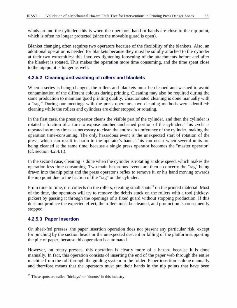
IRSST - Validation of a Mechanical Hazard Fault Tree for Interventions in Printing Press Danger Zones 33
winds around the cylinder: this is when the operator's hand or hands are close to the nip point, which is often no longer protected (since the movable guard is open).
Blanket changing often requires two operators because of the flexibility of the blankets. Also, an additional operation is needed for blankets because they must be solidly attached to the cylinder at their two extremities: this involves tightening-loosening of the attachments before and after the blanket is rotated. This makes the operation more time consuming, and the time spent close to the nip point is longer as well.
4.2.5.2 Cleaning and washing of rollers and blankets
When a series is being changed, the rollers and blankets must be cleaned and washed to avoid contamination of the different colours during printing. Cleaning may also be required during the same production to maintain good printing quality. Unautomated cleaning is done manually with a "rag." During our meetings with the press operators, two cleaning methods were identified: cleaning while the rollers and cylinders are either stopped or rotating.
In the first case, the press operator cleans the visible part of the cylinder, and then the cylinder is rotated a fraction of a turn to expose another uncleaned portion of the cylinder. This cycle is repeated as many times as necessary to clean the entire circumference of the cylinder, making the operation time-consuming. The only hazardous event is the unexpected start of rotation of the press, which can result in harm to the operator's hand. This can occur when several units are being cleaned at the same time, because a single press operator becomes the "master operator" (cf. section 4.2.4.1.).
In the second case, cleaning is done when the cylinder is rotating at slow speed, which makes the operation less time-consuming. Two main hazardous events are then a concern: the "rag" being drawn into the nip point and the press operator's reflex to remove it, or his hand moving towards the nip point due to the friction of the "rag" on the cylinder.
From time to time, dirt collects on the rollers, creating small spots25 on the printed material. Most of the time, the operators will try to remove the debris stuck on the rollers with a tool (hickey-picker) by passing it through the openings of a fixed guard without stopping production. If this does not produce the expected effect, the rollers must be cleaned, and production is consequently stopped.
4.2.5.3 Paper insertion
On sheet-fed presses, the paper insertion operation does not present any particular risk, except for pinching by the suction heads or the unexpected descent or falling of the platform supporting the pile of paper, because this operation is automated.
However, on rotary presses, this operation is clearly more of a hazard because it is done manually. In fact, this operation consists of inserting the end of the paper web through the entire machine from the roll through the guiding system to the folder. Paper insertion is done manually and therefore means that the operators must put their hands in the nip points that have been
25 These spots are called "hickeys" or "donuts" in this industry.

34 Validation of a Mechanical Hazard Fault Tree for Interventions in Printing Press Danger Zones - IRSST
stopped, and then the press operators must temporarily start the press to make the paper advance. This advancing is generally done in hold-to-run control mode. The risk of a fall from heights, mentioned earlier, is present during paper threading on multi-level rotary presses. Paper threading is done following a change in roll format (planned paper change) or following a paper break during production (corrective action under time pressure). Changing from one roll to another during production is generally done in automatic mode with little intervention and therefore little risk.
During one visit, in addition to participating in paper threading on a large two-level rotary press, the research team also witnessed a significant paper jam in the folder. Paper threading was directed by an instructor. The research team's active participation in this operation made us realize the complexity of this intervention and the associated risks: risk of crushing in nip points, risk of falls from heights, etc. The complexity is due to different factors: the necessary coordination between the different people, the required alignment of the web of paper to avoid its jamming, access to unprotected nip points, paper threading at heights (e.g., at the folder).
The paper jam observed at the folder during this visit made the research team aware that lockout is not the most practical and most effective means for saving time and reducing the required repetitive back and forth movements to clear this machine's paper jam. The instructor that we met also indicated that incorrect paper tension or the paper's intrinsic properties, such as its humidity and its recycled fibre content, can cause a paper break. Using strong paper, and therefore containing less recycled fibre, reduces the risks of paper tears26 and consequently, the need for the related intervention. Paper or paper ends sticking on different rollers can also cause paper breaks (Figure 5).
Figure 5: End of paper stuck (in the circle) on a blanket
4.3 General observations from the visits
In general, we learned from our visits that the terminology and the meaning related to this terminology could change from one printing company to the next. For example, for some press operators, the terms jog and inch did not have the same meaning, while for others, the two terms were synonyms. This lack of uniformity in the terms used in the printing company is therefore a risk for error in the frequent communications between press operators.
The work environment is also subject to improvement in terms of lighting, noise and particularly physical accessibility for older presses (steps, uneven surfaces, etc.). On modern presses in recently built plants, these physical constraints tended to be less common.
Despite many improvements, the older presses generally had nip points whose access was not safeguarded, whereas more resent presses were equipped with fixed and movable guards as well as safety devices (e.g., trip nip bars) integrated when the machine was designed. However, some old presses observed had been retrofitted more or less successfully: nip points still accessible,
26 This also reduces the presence of fibres in the ambient air (paper dust).

IRSST - Validation of a Mechanical Hazard Fault Tree for Interventions in Printing Press Danger Zones 35
movable guards without interlock device, etc. Retrofitting work still needs to be done on old presses, particularly if they have to remain in production for several more years.
It should be mentioned that the primary purpose of these visits was to allow the research team to validate the content and logic of the initial ASP imprimerie fault tree, while adding information to it. This goal was completely reached due to the collaboration of ASP imprimerie and the companies in the printing industry. In perusing the final fault tree available in the appendix, the reader can find the different information presented in this section, often in the form of a cause that can lead to crushing of a part of a worker's body in a nip point.


IRSST - Validation of a Mechanical Hazard Fault Tree for Interventions in Printing Press Danger Zones 37
5. MAIN EVOLUTIONS IN THE FT
With all the information collected during the different visits, the research team was able to improve and validate the fault tree. This information was completed by four validation meetings with ASP imprimerie, by various meetings of the research team, as well as by the consultation of documents such as books, standards, records and CSST accident reports.
5.1 Analysis of the format of the initial FT
A fault tree must consist of levels separated by gates. The "cell-gate-cell" sequence must always be applied, and consequently there must be at least two cells to explain a higher level cell. The initial ASP fault tree contains branches where several cells come one after the other. For example (Figure 6): at the original top of the initial tree (Appendix 1.1), "non-compliant installation of the safety device attached to the movable guard" is explained by the "established standards for press safety unknown/not complied with," which is itself explained by an "organizational deficiency in risk management," all without a gate between them. The linkage is completely logical, but if several cells follow one another, this means that there are too many. The three cells were therefore replaced by a single cell. This simplifies the fault tree while making it less cumbersome.
In the first evolution of the FT, there were a few changes in terminology: "incorrect attachment of guard" became "poorly attached guard" which is due either to a "vibration problem," or to the "attachments not complying with design" (or both). In the final version of the FT, this same cause is somewhat more developed. A first reconstruction step in the fault tree was therefore to comply with the "cell-gate-cell" rule.
Next, the research team eliminated the convergent branches present in the initial FT (Figure 7). To be rigorous and use the same logic everywhere, the causes were developed in a single branch, and transfers were used for the other branches. Once the tree corresponded to the construction criteria, a more thorough study of the content of the cells could be done.

38 Validation of a Mechanical Hazard Fault Tree for Interventions in Printing Press Danger Zones - IRSST
Figure 6: Example of modification of the fault tree so that it verifies the form criteria
Incorrect attachment of
guard
Removable or weak attachment
Non-compliant installation of the
safety device attached to the movable guard
Machine vibration
No verification
Preventive maintenance
deficiency
Established standards for press safety unknown/not complied with
Organizational deficiency in
risk management
Poorly attached guard
Vibration problem
Problem withattachments not complying with
design
Incorrect design of guard
Openings too large
Removable guard lacks safety
devices
Incorrectly sized guard
Poorly designed guard
Established standards for press safety unknown/not complied with
No verification
Preventive maintenance
deficiency
Organizational deficiency in
risk management
Improper positioning of the
guard in relation to the danger zone
Movable guard without safety
device
Non-compliant distance between the guard and the
danger zone
Incorrectly sized guard
Openings not compliant with
standards
Z
Z Z Z
Figure 7: Example of modification of the fault tree so that it corresponds to the form criteria

IRSST - Validation of a Mechanical Hazard Fault Tree for Interventions in Printing Press Danger Zones 39
5.2 Analysis of the content of the FT
The content of the cells must answer the question "Why?" by reading the tree from top to bottom, and the question "What is the consequence of?" by reading from bottom to top. The second verification step of the initial FT was therefore to ensure that these relationships were properly verified everywhere.
Take the example of sub-system "A" in the initial FT (Appendix 1.2). It indicates that movement was initiated in controlled action mode (A2) (i.e., at reduced speed, as compared to production mode), either because the movement was initiated at limited speed (e.g., Crawl) (A5), or because movement is controlled by the operator (e.g., jog) (A4). If you consider the "Why?" relationship between (A2) and (A4), you realize that it is not verified: it is not because the operator can control the movement that the movement will be initiated. In fact, the relationship will be verified if you understand the word "controlled" to mean "activated." After verification with an advisor from ASP imprimerie who was working on the project, it in fact had this meaning when it was included.
Much effort was therefore put into clearly understanding and being certain about the meaning of the terms used in the initial version of the FT. For simplicity and clarity, the words in the cells are as concise as possible, which can lead to confusion or interpretation problems. The skill of a fault tree writer is to make the fault tree as concise as possible, while at the same time as reliable as possible for reading, without misinterpretation. This work was important, considering the absence of the designer of the initial FT. From the standpoint of avoiding all interpretation errors, the research team went to ASP imprimerie in order to clarify the content and the logical relationship between certain cells in the initial fault tree. The layout of these cells could then be appropriately organized and their content reformulated when necessary. 5.3 Subsequent evolutions of the FT
As previously explained, modifications to content and form were first made following analysis of the original fault tree and the collection of information from various sources. The main evolutions described in this section primarily involve the top part of the fault tree, because the upper part has an impact on all the rest of the fault tree.
5.3.1 Evolution #1
The following changes were made in the context of the first evolution of the initial FT (Figure 8): The title of the undesirable event: "Crushing between two rollers/cylinders of presses
during an operation" was replaced by "Crushing of a worker by one or more rollers/cylinders of a press during an operation." Justification: a nip point is not created just by two rollers or cylinders, but can consist of a single rotating roller forming a pinch zone with a fixed or moving object (e.g., a sheet of paper).
Addition of the "Strong adherence…" condition, because at this stage of reflection we concluded that to be crushed, you had not only to be drawn along, but there also had to be a sufficiently large force to hold you against the wall of the cylinder(s).

40 Validation of a Mechanical Hazard Fault Tree for Interventions in Printing Press Danger Zones - IRSST
The third level of this intermediate version of the fault tree essentially repeats the content of the second level of the initial fault tree. However, the word "rotation" specifies the type of movement of the roller or cylinder.
Another cell specifies that a worker can access more than one danger zone simultaneously, contrary to what was written in the initial fault tree.
In the ASP fault tree, the "presence of a nip point" is explained by the causes: "No protection" and "Inadequate guard." In this first evolution of the fault tree, the same idea was retained, but reorganized: these two causes are combined under the heading "Lack of protection." Added to this cause is the "layout of the rollers/cylinders forming the nip point," which introduces the different possible geometries that can explain the presence of a nip point.
Figure 8: 1st version of the top of the fault tree
5.4 Evolution #2
Up to this point in the FT, aspects remained that were rather imprecise or that did not rigorously comply with the relationships between the levels (cause/consequence). For example, since the gate used was AND, this assumed that all the following conditions had to be met for a worker to be drawn in, while this was not necessarily the case. At this level at the top of the fault tree (with
Crushing of a worker by one or more rollers/cylinders of a press
during an operation
Presence of a nip point
Drawing in of part of the worker’s body or his clothing
Worker accesses danger zone(s)
Moving cylinders or rollers (rotation)
ALack of
protectionLayout of rollers/
cylinders forming the nip point
Strong adherence between a part of a worker’s body, his clothing, or his tool and a moving cylinder/roller
H

IRSST - Validation of a Mechanical Hazard Fault Tree for Interventions in Printing Press Danger Zones 41
a somewhat catchall description), there were extra causes that would be better placed at a lower level (Figure 9).
Figure 9: 2nd version of the top of the fault tree
5.4.1 Evolution #3
The concepts of hazard and hazardous situation are found at the same level, but this is impossible according to the accident process (Appendix 2). The top of the fault tree was therefore changed, as shown in evolution #3 (Figure 10).
Drawing-in is now explained only by the existence of a drawing-in zone and the presence of a part of the body in the danger zone. The layout of the rollers forming a nip point27 and the movement of the rollers will be found in the explanation of the existence of a drawing-in zone.
Furthermore, the "hazards involved in the three operations" cell in the previous evolution disappears. At the start, this cell was intended to separate the risks by operation. By describing the hazards at this level, the question "Why?" could not to be answered by descending the fault tree, or the "What is the consequence of?" question by going back up. Also, the hazard mainly studied is the same for all the operations, namely the rotation of rollers, creating a nip point.
27 The question of whether to put "danger zone," "drawing-in zone" or even "nip point" was asked for a long time. It was only in evolution #6 of the fault tree that the choice fell on "nip point" because in the companies, people talk about "nip points" (rarely about "drawing-in zone") and also, the term "danger zone" is too vague at this level in the fault tree.
Crushing of a worker by one or more rollers/cylinders of a press
during an operation
Drawing in of part of the worker’s body
Worker is in a hazardous situation
Moving cylinders or rollers (rotation)
Layout of rollers/cylinders forming the nip
point
Strong adherence between a part of a worker’s body, his clothing, or his tool and a moving cylinder/roller
Inability to access the emergency
stop button in time
Hazards involved in the three operations
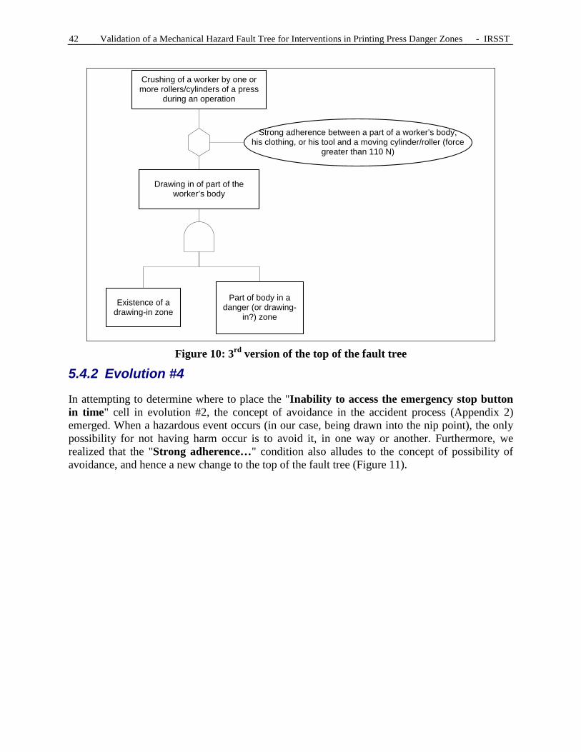
42 Validation of a Mechanical Hazard Fault Tree for Interventions in Printing Press Danger Zones - IRSST
Figure 10: 3rd version of the top of the fault tree
5.4.2 Evolution #4
In attempting to determine where to place the "Inability to access the emergency stop button in time" cell in evolution #2, the concept of avoidance in the accident process (Appendix 2) emerged. When a hazardous event occurs (in our case, being drawn into the nip point), the only possibility for not having harm occur is to avoid it, in one way or another. Furthermore, we realized that the "Strong adherence…" condition also alludes to the concept of possibility of avoidance, and hence a new change to the top of the fault tree (Figure 11).
Drawing in of part of the worker’s body
Part of body in a danger (or drawing-
in?) zone
Existence of a drawing-in zone
Crushing of a worker by one or more rollers/cylinders of a press
during an operation
Strong adherence between a part of a worker’s body,his clothing, or his tool and a moving cylinder/roller (force
greater than 110 N)

IRSST - Validation of a Mechanical Hazard Fault Tree for Interventions in Printing Press Danger Zones 43
Figure 11: 4th version of the top of the fault tree
5.4.3 Evolution #5
With the previous provision, the content of the lower levels following the "Part of body, clothing or tool in a drawing-in zone" cell posed a problem. In fact, there was possible confusion between direct drawing-in of a body part caught in the nip point, and the indirect drawing-in of a body part by a tool caught in the nip point. The fault tree must be clear and not lead to confusion. The top of the fault tree was therefore changed again (Figure 12).
Figure 12: 5th version of the top of the fault tree
Crushing of a worker by one or more rollers/cylinders of a
press during an operation
Drawing in of part of the worker’s body Impossibility of avoidance
Existence of a drawing-in zone
Part of body, clothing, or tool in a drawing-in zone
P
Crushing of a worker by one or more rollers/cylinders of a
press during an operation
Cylinders or rollers (forming the nip point)
moving (rotation)Impossibility of avoidance
Part of body caught in the nip
point

44 Validation of a Mechanical Hazard Fault Tree for Interventions in Printing Press Danger Zones - IRSST
In this figure, the "Cylinders or rollers moving" and "Presence of a nip point" concepts in the original fault tree were combined here in the same cell. This is explained as follows: in evolutions #3 and #4, the existence of a drawing-in zone was explained by the presence of a nip point geometry AND by the presence of cylinders or rollers moving (rotation). The geometry of a nip point is the pinch zone created by two rollers or by one roller and a fixed or movable object. We found it unnecessary to describe such a geometry in the fault tree, which explains why the cells were combined.
Furthermore, there is a problem with this configuration, because the hazardous event does not arise. The hazardous situation (moving cylinders + body part in the nip point) leads directly to the harm. The previous version was more rigorous from this standpoint. By considering it again and by adjusting the text in the cells, the fault tree becomes clearer and more rigorous regarding the accident process. These changes bring us to the sixth evolution in the fault tree. 5.4.4 Evolution #6
We decided to simplify the top of the fault tree (Figure 13) to make the conveyed information more understandable by the operator or press maintenance person or by anyone else interested in the causes of crushing in a printing press nip point. The simplicity of this new layout of the top of the fault tree lies in its more systematic presentation: all harm (the accident) occurs due to a hazardous event that the victim could not avoid. This hazardous event28 occurs following a hazardous situation: someone in contact with or near the hazard. In the subsequent versions of the fault tree, in general, the first two levels after the top of the fault tree did not undergo major changes. Modifications were mainly made to specific logical combinations of causes at lower levels of the fault tree, following questions that were raised, primarily during the validation meetings with representatives of ASP imprimerie.
28 Numbers 1 and 2 (Figure 13) were added respectively to the "voluntary access..." and "involuntary access..." causes. This was done to allow the reader to associate the circumstances of roller rotation start-up with the type of access to the nip point. For example, by consulting sub-system "A," one notes that number 1 refers to an unexpected start-up, while number 2 refers to a start-up already in progress and known by all the operators.

IRSST - Validation of a Mechanical Hazard Fault Tree for Interventions in Printing Press Danger Zones 45
Figure 13: 6th version of the top of the fault tree
Crushing of a worker by one or more rollers/cylinders of a
press during an operation
Drawing in of part of the body in the nip point
Impossibility of avoidance
Cylinders or rollers (forming the nip point) moving
(rotation)
Part of body in nip point
1Voluntary access to
the nip point because the machine is
stopped
2Involuntary access to the nip point (during
rotation of rollers/cylinders)
A
B C
D
PersonHazard
Hazardoussituation
Avoidance Hazardousevent
HARM


IRSST - Validation of a Mechanical Hazard Fault Tree for Interventions in Printing Press Danger Zones 47
6. RESULTS
6.1 The final FT
The final FT consists of 10 levels and 300 causes for the undesirable event. It also contains normative and regulatory references specifying guidelines or a situation for eliminating the mentioned cause. Due to the size of the FT and to lighten the text, an abridged version (Figure 14) of the final FT is presented below. The entire fault tree is found in Appendix 3: the first partis the abridged fault tree, while the subsequent appendices present the ramifications. The latter are divided into four main sub-systems: A, B, C and D, each consisting of a certain number of sub-systems. For clarity, icons have been added to the abridged tree in order to see the sequence leading to the undesirable event. The legend for the FT is detailed in Table 14.
Table 14: Legend for the FT GATES GENERAL SYMBOLS
AND
output
input
Gate indicating that all the causes at its input must exist to obtain the output consequence.
Symbol for the undesirable event (the accident).
OR
input
output Gate indicating that one of the causes is sufficient at its input to obtain the output consequence.
Symbol for intermediate cause (or event). This is developed by subsequent causes (or events).
Inhibition gate to which is (are) connected the condition(s) that can lead to the event in the next level above.
Conditioning symbol. It is an extension of the inhibition gate.
TRANSFER SYMBOLS
Symbol for a cause not developed due to lack of information, or in order to simplify the fault tree when sufficient details are known (this symbol is found in the last level presented in a branch of the fault tree).
Transfer to the corresponding sub-system (identified) in the fault tree. Sub-system designated by a part of an FT which is a group of related causes (this simplifies the FT by avoiding repetition).
Symbol for a cause related to an action or a normal state (e.g., a maintenance activity on the printing press).
Identifies the sub-system (identified) that the previous symbol transferred to.
Symbol for a basic cause, i.e., not requiring any development (this symbol is found in the last level presented in a branch of the fault tree).

48 Validation of a Mechanical Hazard Fault Tree for Interventions in Printing Press Danger Zones - IRSST
Figure 14: Abridged FT
6.1.1 Top of the FT
The top of the FT (Figure 14) starts with the above-mentioned undesirable event (the harm) and presents the first levels of combinations of causes related to this harm. If harm occurs, it means that there was a hazardous event (being drawn into the nip point) AND that the operator was unable to avoid the potential harm (impossibility of avoidance)—developed in "D." Being drawn into the nip point can occur only if the cylinders are rotating (hazard)—developed in "A"—AND a part of the body is in the nip point. The hazardous situation consists of the presence of part of the human body (hand) near or in the nip point.
Finally, only two possibilities explain why the operator's hand is caught in the nip point: either he accessed it voluntarily because the rollers were initially stopped—developed in "B," or he accessed it involuntarily while the rollers were already turning)—developed in "C."
AND
Crushing of part of a worker's body by one or more rollers/
cylinders of a press during an operation
1 ou 2Involuntary
access to the nip point (machine
stopped or operating)
Part of body in nip point
OR
1Voluntary
access to the nip point
because the machine is
stopped
Drawing in of part of body in nip point
AND
Cylinders or rollers (forming the nip point) rotating
OR
Press not locked out
AND
AND
Why
?
Con
sequ
ence
Impossibility of avoidanceD
OP
A
1Start-up initiated by
someone else without the operator’s
knowledge (from this operator's work zone or elsewhere on the
press)
1Untimely
start-up (for all operators)
2Press
operating (high or low
speed)E
G
F B
H Nip point is accessible
Need for intervention in a
nip point
I P
C
H Nip point is accessible
I P
Unexpected movement by
operator towards the nip point
Need for intervention close
to a nip point
L MKJ N
Machine stopped or machine soon tobe started (warning signal given) but the
operator thinks he has the time to perform his intervention
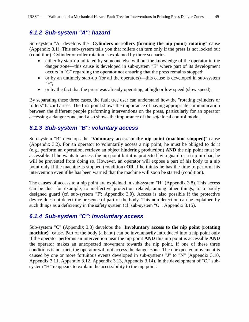
IRSST - Validation of a Mechanical Hazard Fault Tree for Interventions in Printing Press Danger Zones 49
6.1.2 Sub-system "A": hazard
Sub-system "A" develops the "Cylinders or rollers (forming the nip point) rotating" cause (Appendix 3.1). This sub-system tells you that rollers can turn only if the press is not locked out (condition). Cylinder or roller rotation is explained by three scenarios:
• either by start-up initiated by someone else without the knowledge of the operator in the danger zone—this cause is developed in sub-system "E" where part of its development occurs in "G" regarding the operator not ensuring that the press remains stopped;
• or by an untimely start-up (for all the operators)—this cause is developed in sub-system "F";
• or by the fact that the press was already operating, at high or low speed (slow speed).
By separating these three cases, the fault tree user can understand how the "rotating cylinders or rollers" hazard arises. The first point shows the importance of having appropriate communication between the different people performing interventions on the press, particularly for an operator accessing a danger zone, and also shows the importance of the safe local control mode.
6.1.3 Sub-system "B": voluntary access
Sub-system "B" develops the "Voluntary access to the nip point (machine stopped)" cause (Appendix 3.2). For an operator to voluntarily access a nip point, he must be obliged to do it (e.g., perform an operation, retrieve an object hindering production) AND the nip point must be accessible. If he wants to access the nip point but it is protected by a guard or a trip nip bar, he will be prevented from doing so. However, an operator will expose a part of his body to a nip point only if the machine is stopped (condition) OR if he thinks he has the time to perform his intervention even if he has been warned that the machine will soon be started (condition).
The causes of access to a nip point are explained in sub-system "H" (Appendix 3.8). This access can be due, for example, to ineffective protection related, among other things, to a poorly designed guard (cf. sub-system "I": Appendix 3.9). Access is also possible if the protective device does not detect the presence of part of the body. This non-detection can be explained by such things as a deficiency in the safety system (cf. sub-system "O": Appendix 3.15).
6.1.4 Sub-system "C″: involuntary access
Sub-system "C" (Appendix 3.3) develops the "Involuntary access to the nip point (rotating machine)" cause. Part of the body (a hand) can be involuntarily introduced into a nip point only if the operator performs an intervention near the nip point AND this nip point is accessible AND the operator makes an unexpected movement towards the nip point. If one of these three conditions is not met, the operator will not access the danger zone. The unexpected movement is caused by one or more fortuitous events developed in sub-systems "J" to "N" (Appendix 3.10, Appendix 3.11, Appendix 3.12, Appendix 3.13, Appendix 3.14). In the development of "C," sub-system "H" reappears to explain the accessibility to the nip point.

50 Validation of a Mechanical Hazard Fault Tree for Interventions in Printing Press Danger Zones - IRSST
6.1.5 Sub-system "D": impossibility of avoidance
Sub-system "D" (Appendix 3.4) develops the "Impossibility of avoidance" cause. In this fault tree, several reasons are detailed which, combined or not, can result in the worker not being able to avoid the harm. One of these reasons is the inability to initiate stopping of the machine (developed by sub-system "O"—Appendix 3.15). The various means of avoidance are the last option for the operator to avoid harm when a hazardous event occurs. 6.2 Final FT: discussion and limitations
The final FT is the most thorough fault tree that the research team was able to develop in the framework of this study. However, some causes may be missing because it is an exercise done a priori in a deductive way. By consulting other press operators or other printing press technicians, other causes could be identified for the undesirable event studied. The presence of diamonds in the last levels of the final fault tree shows that the possible causes of the accident dealt with could be covered in greater detail. However, in the framework of our study, the level of detail reached in these diamonds is sufficient, because the fault tree developed is intended for press operators, to alert them to the different actions and situations that could lead to the above-mentioned accident. If the FT had been developed for personnel specialized in control systems, the diamonds in sub-system "F" (Appendix 3.6) would have been developed to identify more thoroughly the original causes of an untimely start-up. Since this is not the purpose of this FT, the research team decided to limit the detail of the fault tree to these objectives. In the opinion of the research team, the final FT is adaptable to other types of machines with nip points and where the causes of crushing of a part of a worker's body in this type of hazardous zone need to be investigated. 6.3 Possibility of analysis of the final FT
Based on section 2.1.1 "Definition and usefulness of a fault tree," an FT is a tool that, in addition to providing information on the failures or causes leading to an undesirable event, is effective in identifying what requires intervention, in order to reduce or eliminate a given accident risk [40]. Methods exist for identifying what needs action, including the method called "defense in depth."
6.3.1 Concept of "defense in depth"
Defense in depth is a process for risk management and control [19, 21]. It involves using several safety techniques to reduce the risk, when a particular safety component is compromised or failing. The designers envisage protective systems that will avoid a succession of undesirable events leading to the final unwanted event. These protection systems represent barriers, directly related to the options chosen in design and operation, which are implemented to reduce the identified risks. The barriers can be of several types:
• A technological device (fixed guards, movable guards, etc.); • A procedural provision (regular verification of the emergency braking system);

IRSST - Validation of a Mechanical Hazard Fault Tree for Interventions in Printing Press Danger Zones 51
o A person can be a barrier (based on his senses, i.e., an operator stops a machine due to unusual noises);
• An organizational provision (i.e., task separation).
Construction of an FT is a very good starting point that subsequently allows rapid identification of the different points where a barrier can be installed.
6.3.2 Analysis
The fault tree can be analyzed according to four different logics, but that fulfill the same ultimate objective, that of eliminating or reducing the risk associated with printing press nip points. In terms of defense in depth, this can be done by identifying the most judicious locations for placing a barrier and the type of barrier. Since risk elimination can only be achieved by eliminating the hazard (the nip point), it seems that this solution cannot be used here, because printing presses are designed with nip points.
As a result, the first scenario for risk reduction would be to influence the different risk parameters: frequency, severity, as well as the appearance of the hazardous event or the possibility of avoidance. This is the scenario that is detailed in the remainder of this section.
The work therefore involves asking the following questions for each of the hazardous zones: • Are there technical, human or organizational (or other) means for:
o reducing the severity of the harm? o reducing the frequency of exposure? o reducing the probability of occurrence of the hazardous event? o improving the possibility of avoidance?
The second scenario involves using different logical reasoning. The question can also be asked using risk reduction hierarchical logic [35]:
• Is it possible to: o reduce the severity of the harm? o use fixed guards? o use movable guards? o use protective devices? o warn the press users or alert them to the risks? o use work methods? o use personal protective equipment?
A third scenario, which can also be used, is to categorize the contributing factors (the causes) of the undesirable event mentioned in the FT. Pérusse [36] suggests classifying the contributing factors in five groups related to:29
• the equipment; • the environment; • the organization; • the task;
29 According to an accident analysis method developed by the INRS.

52 Validation of a Mechanical Hazard Fault Tree for Interventions in Printing Press Danger Zones - IRSST
• the individuals.
Next, the choice of barriers where action should be taken will be guided by the relative effectiveness of these five groups: the first three groups (related to the equipment, environment, and the organization) are more effective than the task-related group, which is also more effective than the individual-related group. According to Pérusse, it is in fact more effective to take action on the material factors (namely the machines, safety devices, etc.), ideally in an intrinsic way, than to focus more on the task (which can be influenced by the machine) or on the press operators, in order to make the interventions on printing presses safe.
Finally, the fourth scenario is in fact based on the concept of a fault tree. A fault tree brings together the various possible causes of an accident, organized with gates. Reducing the risk that an accident will occur therefore involves eliminating the occurrence of a maximum of these causes. Concretely, analysis of the fault tree is therefore based first on locating the AND gates. In reality, when an event has several causes that must absolutely happen so that the event occurs, only one cause has to be eliminated so that this event never takes place. Next, it is not necessarily possible to work on all the causes; the causes that will achieve an effective risk reduction must therefore be chosen. The concept of minimum cut [41] can then be used to identify the minimal associations of causes leading to harm.
However, one must remember that each time that the designer installs a guard (technical barrier), he creates an obstacle for operators as well as for maintenance operators. Also, the procedures may not always be easy to be complied with, because they can result in changes for the operators or slow down production. Finally, the organizational means must be kept in place throughout the lifetime of the organization, which requires non-negligible means. It is therefore important to establish the minimum barriers possible, and that the ones chosen are as effective as possible or that their combination is as effective as possible.
6.3.2.1 Reduction of the severity of harm
Reduction of the severity of harm can be achieved on printing presses by using a slow speed. In fact, it is difficult and even impossible to modify the geometry of the nip point on a printing press, if indeed the modified geometry can lead to a reduction in severity. It is also very difficult to modify a press to include retractable rollers [39], knowing that this solution is already being used by printing press designers for a few rollers.
If using a reduced speed [6] is the only existing solution that can be applied to reduce the severity of harm, efforts must be made to ensure that this speed is maintained when it is selected by the press operator. This is the meaning of section 186 of the ROHS and section 6.2.11.9 of ISO 12100:2010 [30]. Reduced speed can, for example, be selected automatically when a previously-identified interlocked guard or interlocked guard with guard locking is opened (technical barrier).
6.3.2.2 Reducing the exposure frequency
Exposure frequency can mainly be reduced on printing presses by non-exposure of the press operator to the hazard. This non-exposure can be achieved by using fixed guards [28, 32] for nip

IRSST - Validation of a Mechanical Hazard Fault Tree for Interventions in Printing Press Danger Zones 53
points, or movable guards, as well as by using protective devices, such as optical beams, a trip nip bar, two-hand control, etc. The main question is to know whether access to the nip point is necessary, and if so, when.
Generally, all the nip points on older machines are not protected. The first exercise involves limiting access to these nip points by means of guards or protective devices. This must be done following a risk analysis. However, caution is necessary with the preceding recommendation and one must remember that guards limit access to the machine. If the tasks are not adapted or do not take into account the limited access to the machine, bypassing will occur voluntarily or involuntarily.30
Nevertheless, it is clear that the presence of a press operator is currently necessary to ensure proper operation of the machine, and even if operations can still be automated, monitoring of the proper operation of the machine by an operator remains necessary. In fact, a person can play the role of a barrier, as mentioned previously: "despite the increasing automation of systems, people remain indispensable for monitoring and acting in the event of a malfunction (free translation) [17]." To make the human barrier reliable, it is important that it be done by organizational means, such as proper training, appropriate and regular communication, and ensuring the appropriation of knowledge and experience in order to optimize and even guarantee the quality of the work and of safety. Safe and clear work procedures must be integrated into the training.
But one also has to question whether the operator must be present near a nip point at all times. If his access can be limited, this is done instead of exposing the press operator to the hazard.
6.3.2.3 Reducing the probability of the hazardous event
Working on reducing the probability of the hazardous event is also a solution. This can be achieved in several ways, but the initial questions related to voluntary or involuntary access rapidly arise, which are themselves related to the concept of stopped machine or rotating machine.
First hypothesis: the operator voluntarily accesses the nip point, because the rollers are stopped (sub-system "A" at the top of the FT). In this case, the operator is able to access a nip point, whose guards have been removed for this purpose. The risk then comes from a possible untimely start-up, from his viewpoint, of the press. In fact, as long as the rollers are stopped, the zone is not hazardous as mentioned in the "Cylinders or rollers (forming the nip point) rotating" cause. In this case, the necessary means must be implemented to prevent any untimely start-up. For example, ISO 14118 [32] lists several possibilities. The problem can be organizational (case of start-up without the operator's knowledge), or more technical (case of untimely start-up for all the operators). Manufacturers can also design the most automated machines possible, thus reducing the need for manual intervention in the nip points.
The question of lockout is at this level. Ideally, lockout that is done properly ensures the workers' safety during any intervention in a printing press danger zone. However, during the field visits,
30 One production manager mentioned to the research team that with the improvement in printing press safety, accidents often occur due to the human factor: either the guards are not put back in place, or safety is bypassed, or even the operators take major risks in order not to have to stop the machine.

54 Validation of a Mechanical Hazard Fault Tree for Interventions in Printing Press Danger Zones - IRSST
we noted that for several technical reasons, lockout represents a major obstacle when the four operations studied must be performed. In fact, when the four observed operations are being properly executed, they require rotation of the rollers, which can be done minimally in stages or by limited movement. Applying lockout in this context would involve the regular padlocking and unpadlocking of the press to perform the four operations, which seems unrealistic to the research team. The most realistic option is to find an alternative method to lockout, within the meaning of standard CSA Z460 [8], for these operations. Of course, this alternative method must be absolutely safe and comply with section 186 of the ROHS.
Second hypothesis: the operator involuntarily accesses a nip point while the rollers are rotating (sub-system "C"). Three conditions are necessary: a need for intervention near (and not "in") a nip point, an unexpected movement by the worker towards the nip point, and the fact that the nip point is accessible. The research team found it more sensible to look for solution scenarios in relation to this last point (cf. previous section). In fact, performing an intervention close to a danger zone, without having to access it, will be safe as soon as the danger zone is inaccessible. It can then be appropriate to work on the causes of the hazardous event (slipping, falling, etc.) as well as on the need for working near a nip point (cf. previous section).
6.3.2.4 Improving the possibility of avoiding harm
At the top of the FT, it is finally possible to work on the means of avoiding harm. For example, the emergency stop function can be used [10, 12, 27] or the principle of the trip nip bar, as well as the principle of local hold-to-run control allowing work at reduced speed [6].
Regarding the emergency stop, there could be questions about the accessibility of the emergency stop function:
• Are the buttons accessible from all workstations? • Is it more judicious to use an emergency pull-cord? • Is it more judicious to use a teach pendant or a three-position grip switch as in the
robotics industry or integrated manufacturing systems?
The specifications for using a trip nip bar [12, 13] must be properly applied. Section 5.2.10 of NF EN 1010-1:2004 [12] clearly details the application requirements.
Regarding the local hold-to-run control at reduced speed (which allows the operator to stop the rollers from rotating as soon as he feels he is starting to be drawn in), the same questions as for the accessibility of the control apply. This reflection may also result in improvement to the ergonomics of the related task, for example by using a pendent drop handle that allows the press operator to move freely in front of the work zone, rather than having to activate a control button whose spatial position is fixed.

IRSST - Validation of a Mechanical Hazard Fault Tree for Interventions in Printing Press Danger Zones 55
7. CONCLUSION AND DISCUSSION
This study, the result of a request from the Association sectorielle paritaire du secteur de l'imprimerie (ASP imprimerie), consisted of validating the logic and thoroughness of a fault tree developed by ASP imprimerie. This fault tree is a logic diagram that traces the different combinations of causes that can result in the undesirable event, namely the "crushing of part of the body of a worker by one or more rollers/cylinders of a printing press during an operation." In fact, in this activity sector, the operators of these machines (called press operators) suffer many serious accidents, with rotary as well as sheet-fed printing presses. The aim of this fault tree, once corrected and finalized, is to formalize the different causes that can be the reason for an accident, and at the same time, allow safe work procedures to be generated that are applicable during four operations during which the printing press rollers and cylinders must rotate:
1. Cleaning and washing of rollers and blankets, 2. Insertion and removal of plates, 3. Insertion and removal of blankets, 4. Threading of paper.
Since the machine must operate, lockout is therefore not a possible solution. What remains is the application of section 186 of the Regulation respecting occupational health and safety (ROHS), which mentions that if a guard or a protective device is moved or neutralized, additional means must be implemented to ensure the workers' safety. It is along these lines that ASP imprimerie is currently proceeding and it is also what the research team observed during the field visits.
To validate the fault tree, the research team defined a research methodology that allowed it to obtain information about printing presses, to visit companies using these machines, and to meet press operators and to discuss with them their work and their safety. At the same time, the initial fault tree was analyzed according to a logical and rigorous process, while using the available standards in order to have it evolve, step by step, as reported in Chapter 5 of this report.
The field visits were the opportunity to observe recent and older rotary and sheet-fed machines of various sizes in operation. In fact, the research team believes that the printing press sample used for validating the fault tree is representative of the machines used in Québec. From a technical standpoint, many facts emerge from the different visits. Great confusion exists surrounding the meaning of the hold-to-run control mode and the limited movement control mode, in French as well as in English. Different interpretations were collected in the companies; during the visits, the research team became aware that the meaning of the English terms (jog and inch were used more than the French terms) varied from one printing company to the next, whereas the meaning of the French terms varied less. The use of a uniform vocabulary in the industry would limit the confusion about the different control modes. Some machine danger zones, particularly for older machines, were not protected by fixed guards, movable guards or protective devices. Finally, a few characteristics of the safe control mode, associated with movable guards, varied with the presses observed.
From an organizational standpoint, other important facts also emerged from the visits. Inadequate communication and coordination were recognized by the press operators as being contributing factors to the occurrence of hazardous events. The work environment, including

56 Validation of a Mechanical Hazard Fault Tree for Interventions in Printing Press Danger Zones - IRSST
ambient noise, lighting, the physical configuration of the machines, as well as the frequent uneven surfaces were also recognized by the press operators as contributing factors to hazardous events. Finally, the objects used during the different observed tasks can also be the source of hazardous events. All of these points are covered in section 4.3 of the report.
From the logic standpoint, the initial fault tree was significantly remodeled. The evolutions were based on the research team's observations during the visits, on the discussions carried out in companies with the press operators, on the discussions with the employees of ASP imprimerie, as well as on the comments of the expert press operator during one of the validation meetings. Regarding the logic, all the relationships between the different levels can be explained by the two basic questions: "Why?" and "What are the consequences of...?". Finally, the cells are always linked by gates. The fault tree was also enhanced with legislative and normative references related to printing presses. In addition to the causal chain logic, the user has different information at his disposal on safety aspects that can be chosen to improve the safety of these machines.
From all this information, safe procedures can be developed that comply with the current regulations or the concepts conveyed by the standards in the printing industry. The different users of the fault tree will also be able to safeguard printing presses as well as their operation according to the concept of defense in depth. The choice of barriers characteristic of this concept—material, human or organizational barriers—will be made easier by the classification of the causes (factors contributing to the undesirable event) mentioned in the fault tree and guided by one of the four methods of reasoning mentioned in the previous chapter.
Finally, the research team believes that this fault tree can be adapted to other machines with many nip points. In fact, the accident logic as well as the means for safeguarding nip points will remain the same, and only information relating to necessary human presence in or near the danger zone and certain hazardous events will have to be adapted to the new machines.

IRSST - Validation of a Mechanical Hazard Fault Tree for Interventions in Printing Press Danger Zones 57
8. REFERENCES
[1] "Les machines à imprimer rotatives à bobines," Travail & Sécurité, 1970, p 603 to 610.
[2] "Offset imprimerie", Wikipédia. {http://fr.wikipedia.org/wiki/Offset_(imprimerie)} (19 November 2009)
[3] ABECASSIS, P., Andeol, B., Auburtin, G., Beaumont, N., Bediot, G. et al. "Évaluation et prévention des risques dans les petites imprimeries offset," 2003, Institut national de recherche et de sécurité (INRS), pp. 109-150.
[4] ALSACE SANTÉ AU TRAVAIL. "Fiche métiers de l'impression - Technique de l'offset," 2007, 11 pages.
[5] AMERICAN NATIONAL STANDARDS INSTITUTE. "Criteria for safety symbols," ANSI Z 535-3 (2007)
[6] AMERICAN NATIONAL STANDARDS INSTITUTE. "Graphic technology – Safety standard – Printing press systems," ANSI B65.1 (2005)
[7] AMERICAN NATIONAL STANDARDS INSTITUTE. "Performance criteria for safeguarding," ANSI B11.19
[8] CANADIAN STANDARDS ASSOCIATION. "Control of Hazardous Energy – Lockout and Other Methods," CSA Z460 (2005)
[9] CANADIAN STANDARDS ASSOCIATION. "Safeguarding of Machinery," CSA Z432 (2004)
[10] INTERNATIONAL ORGANIZATION FOR STANDARDIZATION. "Safety of machinery - Emergency stop - Principles for design," EN ISO 13850:2008 (ISO 13850:2006)
[11] ASSOCIATION FRANÇAISE DE NORMALISATION. "Exigences de sécurité – Partie 1: exigences communes," NF EN ISO 11111-1
[12] ASSOCIATION FRANÇAISE DE NORMALISATION. "Sécurité des machines - Prescriptions de sécurité pour la conception et la construction de machines d'impression et de transformation du papier - Partie 1: prescriptions communes," NF EN 1010-1 (2004)
[13] ASSOCIATION FRANÇAISE DE NORMALISATION. "Sécurité des machines : Prescriptions de sécurité pour la conception et la construction de machines d'impression et de transformation du papier - Partie 2 : Machines d'impression et de vernissage y compris les machines et les équipements de pré-presse," NF EN 1010-2 (2004)
[14] BRITISH STANDARDS INSTITUTION. "Guidance on safe use of machinery," PD 5304 (2005)
[15] COMMISSION DE LA SANTÉ ET DE LA SÉCURITÉ DU TRAVAIL DU QUÉBEC. Rapport d'enquête d'accident : accident avec blessures survenu le 24 août 1981 (sommaire : un pressier a les deux mains écrasées entre deux cylindres d'une presse d'imprimerie), EN-001082 Québec, CSST, 1981.

58 Validation of a Mechanical Hazard Fault Tree for Interventions in Printing Press Danger Zones - IRSST
[16] COMMISSION DE LA SANTÉ ET DE LA SÉCURITÉ DU TRAVAIL DU QUÉBEC. Rapport d'enquête d'accident : accident avec blessures survenu le 27 mai 1984 (sommaire : un pressier a le pouce gauche arraché dans l'angle rentrant de rouleaux en réglant une presse), EN-001544, Québec, CSST, 1984.
[17] DIDELOT, Armelle. Contribution à l'identification et au contrôle des risques dans le processus de conception, Thèse de Doctorat en Génie des Systèmes Industriels, Institut national de recherche et de sécurité (INRS), 2002, 229p.
[18] GAGNÉ, Nicolas, Massé, Serge, Turcot, Denis, Giraud, Laurent and Sirard, Christian. "La sécurité des cardes - Identification des risques et exploration des possibilités d'amélioration," Montréal, IRSST, 2004, 182 pages.
[19] GARBOLINO, Emmanuel. "La défense en profondeur - Contribution de la sûreté nucléaire à la sécurité industrielle," Paris, Éditions TEC & DOC, 2008, 66 pages.
[20] GIRAUD, Laurent. "Machine Safety - Prevention of Mechanical Hazards - Fixed Guards and Safety Distances," RG-597, Montréal, 2009, 71 pages.
[21] HOLLNAGEL, Erik. "Barriers and Accident Prevention," Hampshire, Ashgate Publishing, 2006, 208 pages.
[22] LAURENZI, Nathalie. Fiche technique : "Action sur les machines - Angles rentrants : les repérer pour se protéger," Montréal, Association paritaire de santé et de sécurité du travail, secteur imprimerie et activités connexes, 2009, 4 pages.
[23] LAURENZI, Nathalie. Guide : "Comprendre les risques associés aux machines en imprimerie pour agir en prévention," Montréal, Association paritaire de santé et de sécurité du travail, secteur imprimerie et activités connexes, 2006, 67 pages.
[24] LIEVENS, C. "Sécurité des systèmes," Toulouse, Cépaduès - Édition, 1976, 341 pages.
[25] LOIS ET RÈGLEMENTS DU QUÉBEC. "Regulation respecting occupational health and safety" (ROHS), 2013.
[26] MARSOT, J., Klein, R., Pagliero, D. and Dei-Svaldi, D. "Sécurité des machines et des équipements de travail - Circuits de commande et de puissance. Principes d'intégration des exigences de sécurité," Institut national de recherche et de sécurité (INRS), 2003, 35 pages.
[27] INTERNATIONAL ORGANIZATION FOR STANDARDIZATION. "Safety of machinery – Emergency stop – Principles for design," ISO, ISO 13850: 2006
[28] INTERNATIONAL ORGANIZATION FOR STANDARDIZATION. "Safety of machinery – Safety distances to prevent hazard zones being reached by upper and lower limbs, " ISO, ISO 13857: 2008
[29] INTERNATIONAL ORGANIZATION FOR STANDARDIZATION. "Safety of machinery – interlocking devices associated with guards – Principles for design and selection," ISO, ISO 14119: 1998
[30] INTERNATIONAL ORGANIZATION FOR STANDARDIZATION. "Safety of machinery -- General principles for design -- Risk assessment and risk reduction" ISO, ISO 12100:2010
IRSST - Validation of a Mechanical Hazard Fault Tree for Interventions in Printing Press Danger Zones 59
[31] INTERNATIONAL ORGANIZATION FOR STANDARDIZATION. "Safety of machinery – Prevention of unexpected start-up," ISO, ISO 14118: 2000
[32] INTERNATIONAL ORGANIZATION FOR STANDARDIZATION. "Safety of machinery – Guards – General requirements for the design and construction of fixed and movable guards," ISO, ISO 14120
[33] INTERNATIONAL ORGANIZATION FOR STANDARDIZATION. "Graphical symbols – Safety colours and safety signs – Part 3: Design principles for graphical symbols for use in safety signs," ISO, ISO 3864 - 3: 2006
[34] INTERNATIONAL ORGANIZATION FOR STANDARDIZATION. "Safety of machinery – Integrated manufacturing systems – Basic requirements," ISO, ISO 11161:2007
[35] PAQUES, J.-J., BOURBONNIÈRE, R., DAIGLE, R., DUCHESNE, D., TRUDEL, C., HUNYNH, T., ELISKOF, S. and SCHREIBER, L. "Sécurité des machines : phénomènes dangereux, situations dangereuses, événements dangereux, dommages," Pochette Montréal, CSST, IRSST, 2004.
[36] PÉRUSSE, Michel. "Le coffre à outils de la prévention des accidents en milieu de travail," Napierville, Groupe de communication Sansectra, 1995, 302 pages.
[37] RAVALLEC, Céline. "Le Monde Imprimerie - La réduction des risques a bonne presse," Travail & Sécurité, juin 2008, p. 2-11.
[38] RELIABILITY ANALYSIS CENTER (RAC). "Fault tree analysis application guide," 1990, 55 pages.
[39] STANDARDS AUSTRALIA. "Conveyors - Safety requirements," AS 1755 (2000)
[40] ANDÉOL-AUSSAGE, B., MONTEAU, M., Risques professionnels : analyse et évaluation, Techniques de l'Ingénieur, SE3920, 2007.
[41] MORTUREUX, Y., Arbres de défaillance, des causes et d'événement, Techniques de l'Ingénieur, SE4050, 2002.

60 Validation of a Mechanical Hazard Fault Tree for Interventions in Printing Press Danger Zones - IRSST
APPENDIX 1: INITIAL FAULT TREE
Appendix 1.1: Initial fault tree (Top)
P1Crushing between two press
rollers/cylinders during an operation
P11Organizational
deficiency in risk communication
P3Cylinders or rollers
moving
P2Presence of a nip
point
P4Worker accesses
a danger zone
A B
P5No protection
P6Inadequate guard
P7Identified and
unprotected nip point
P9Organizational
deficiency in risk management and
monitoring
P8Unidentified or
unknown nip point (e.g., reverse
mode)
P10No safety signs or inadequate signs
P12Poorly designed
guard
P15Incorrectly sized
guard
P16Too large openings
P17Removable guard
without safety devices
P18Established standards
for press safety unknown/not complied
with
P19No verification
P20Organizational
deficiency in risk management
P13Incorrect
attachment of guard
P14Unsuitable
material (e.g., fragile, flexible)
P22Machine vibration
P23Removable or
weak attachment
P24Non-compliant
installation of the safety device
attached to the movable guard
P25No verification
P26Established
standards for press safety unknown/not complied with
P29Established
standards for press safety unknown/not complied with
P28Organizational
deficiency in risk management
P27Deficiency in preventive
maintenance
P21Deficiency in preventive
maintenance
P30Organizational
deficiency in risk management
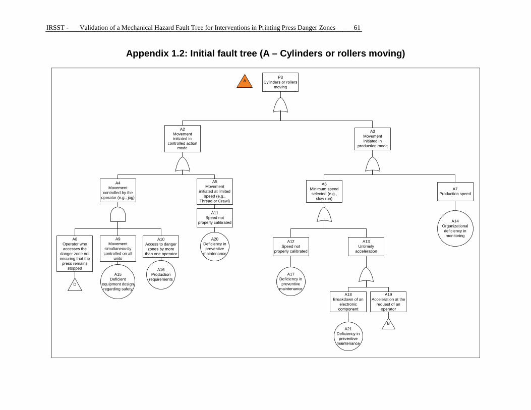
IRSST - Validation of a Mechanical Hazard Fault Tree for Interventions in Printing Press Danger Zones 61
Appendix 1.2: Initial fault tree (A – Cylinders or rollers moving)
AP3
Cylinders or rollers moving
A2Movement initiated in
controlled action mode
A3Movement initiated in
production mode
A4Movement
controlled by the operator (e.g., jog)
A5Movement
initiated at limited speed (e.g.,
Thread or Crawl)
A6Minimum speed selected (e.g.,
slow run)
A7Production speed
A8Operator who accesses the
danger zone not ensuring that the
press remains stopped
A9Movement
simultaneously controlled on all
units
A10Access to danger
zones by more than one operator
D
A15Deficient
equipment design regarding safety
A11Speed not
properly calibrated
A20Deficiency in preventive
maintenance
A12Speed not
properly calibrated
A17Deficiency in preventive
maintenance
A13Untimely
acceleration
A18Breakdown of an
electronic component
A21Deficiency in preventive
maintenance
A19Acceleration at the
request of an operator
B
A14Organizational deficiency in monitoring
A16Production
requirements

62 Validation of a Mechanical Hazard Fault Tree for Interventions in Printing Press Danger Zones - IRSST
Appendix 1.3: Initial fault tree (B1 – Worker accesses danger zone, plate insertion)
B1Worker accesses
danger zone
B2Untimely start-up
B
B3Decreased vigilance
B4Inability of operator to monitor
the control system
B8Stress or fatigue
B9Work posture does not
allow controls to be reached
B10Plate gripped with
both hands
B13Difficult access zone for plate
insertion
B14Machine design
B5Breakdown of an electronic component
B6Omitting to
initiate SAFE
B7Substance
consumed that reduces vigilance
(medication)
B11Deficient
planning of work
B12Workload
B15Manual insertion method
B16Plate
dimension
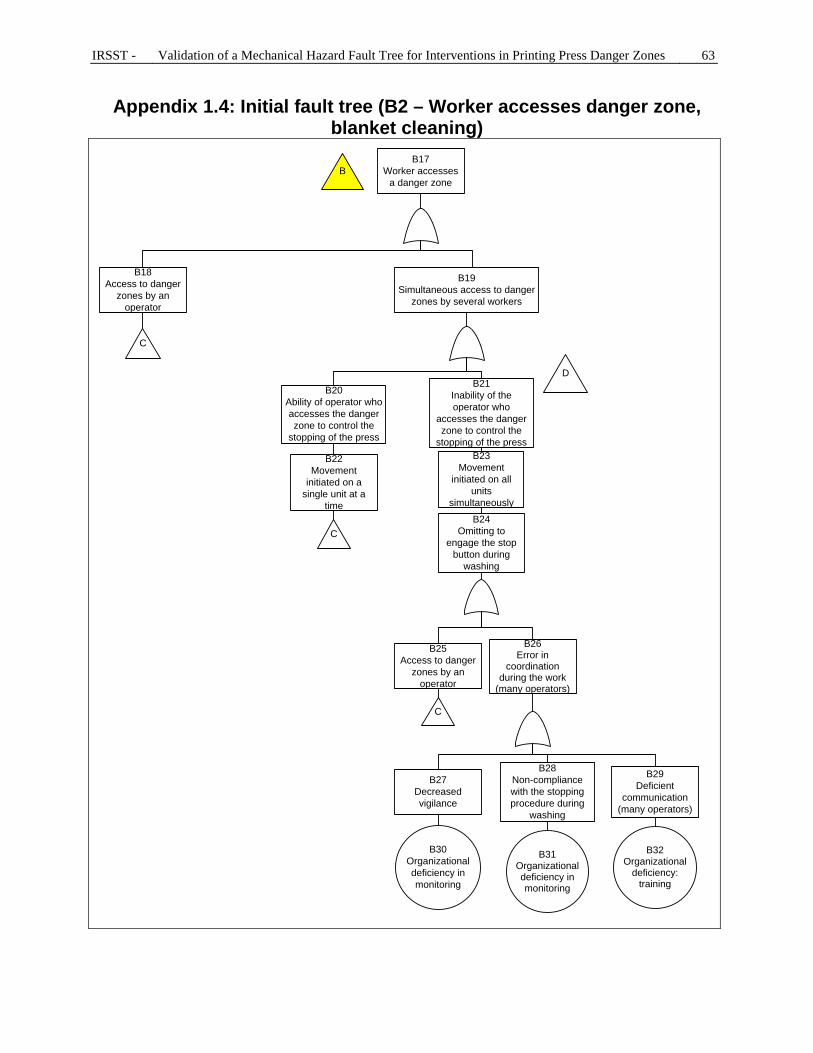
IRSST - Validation of a Mechanical Hazard Fault Tree for Interventions in Printing Press Danger Zones 63
Appendix 1.4: Initial fault tree (B2 – Worker accesses danger zone, blanket cleaning)
BB17
Worker accesses a danger zone
B18Access to danger
zones by an operator
C
B19Simultaneous access to danger
zones by several workers
B20Ability of operator who accesses the danger zone to control the
stopping of the press
B22Movement
initiated on a single unit at a
time
C
B21Inability of the operator who
accesses the danger zone to control the
stopping of the pressB23
Movement initiated on all
units simultaneously
B24Omitting to
engage the stop button during
washing
B25Access to danger
zones by an operator
C
B26Error in
coordination during the work
(many operators)
B27Decreased vigilance
B28Non-compliance with the stopping procedure during
washing
B29Deficient
communication (many operators)
B30Organizational deficiency in monitoring
B31Organizational deficiency in monitoring
B32Organizational
deficiency: training
D

64 Validation of a Mechanical Hazard Fault Tree for Interventions in Printing Press Danger Zones - IRSST
Appendix 1.5: Initial fault tree (C – Access to danger zones by an operator)
C1Access to danger
zones by an operator
C
C2Poor visibility of the danger zone
C3Inability to reach the emergency
stop button in time
C4Drawing in by an
object
C5Decreased vigilance
C6Deficient lighting (dirty or missing)
C15Deficiency in preventive
maintenance
C7Danger zone
recessed
C16Equipment
design
C8No stop button
C9Non-compliant
stop button
C17Established
standards for press safety unknown/not complied with
C10Work posture does not allow
stop button to be reached
C24Organizational
deficiency in risk management
C18Established
standards for press safety unknown/not complied with
C25Organizational
deficiency in risk management
C11Unsafe grip on the
rag
C19Use of too large
gloves
C26Wearing of loose
clothing
C20Use of a frayed
rag
C12Untied long laces
C14Substances
consumed that affect vigilance
C13Stress or fatigue
C23Organizational
deficiency: monitoring
C27Organizational
deficiency: monitoring
C21Workload
C22Deficient planning

IRSST - Validation of a Mechanical Hazard Fault Tree for Interventions in Printing Press Danger Zones 65
APPENDIX 2: ACCIDENT PROCESS AND COMPOSITION OF RISK [35]

66 Validation of a Mechanical Hazard Fault Tree for Interventions in Printing Press Danger Zones - IRSST
APPENDIX 3: FINAL FAULT TREE
Appendix 3.1: Final FT (sub-system "A")
2Press operating
(high or low speed)
1Untimely start-up (for all operators)
OR
FOR
Changing of plates
Insertion/threading of
paper
Cleaning of rollers/
blankets
Changing of blankets
Other operation
(e.g., adjustment)
E
Press not locked out
A
Production
Awaiting production (in slow speed
mode)
Cylinders or rollers (forming the nip point) rotating
ISO 14118-2000chap. 4, 5 and 6
NF EN 1010-1:2004section 5.2.7.4
ROHS (2008)section 185
CSA Z432-04section
6.2.1.9.12.1
1Start-up initiated by someone else without the
operator’s knowledge (from this operator's work zone or elsewhere on the press)
Periodic maintenance
(lubrication, etc.)

IRSST - Validation of a Mechanical Hazard Fault Tree for Interventions in Printing Press Danger Zones 67
Appendix 3.2: Final FT (sub-system "B")
Need for intervention in a nip
point
Nip point is accessible
Clearing paper jams
OR
OR
Paper tearing Paper jam
OR
Falling tool or other object (e.g., rag)
OR
OR
Changing of plates
Changing of blankets
Cleaning of rollers/
blankets
AND
Poorly aligned paper
Sheet of paper remained stuck on a
blanket
Vibration of machine(s) Incorrect maneuver
Periodic maintenance (lubrication, cleaning of rollers, etc.)
Repair following a breakdown/malfunction
B
Other operation
Insertion/threading of
paper
H
Unsuitable tensionon the paperDamp paper Damp paper
ROHS (2008)section186
CSA Z432-04section 14
ROHS (2008)sections185 and 323
Unsuitable paperquality or properties
Inappropriateguiding of the sheet of
paper in the press
Unsuitable paperquality or properties
Machine stopped or machine soon to be started(warning signal given) but the operator thinks he has the
time to complete his intervention
1Voluntary access to
the nip point (machine stopped)
NF EN 1010-1:2004section 5.2.3.2

68 Validation of a Mechanical Hazard Fault Tree for Interventions in Printing Press Danger Zones - IRSST
Appendix 3.3: Final FT (sub-system "C")
C
Decreased vigilance
L
Nip point hardly or not visible
MK
J
Object held or carried (by the
operator) caught in a nip point
Unexpected movement by
operator towards the nip point
OR
AND
2Operator surprised by
an untimely acceleration
N
Need for intervention near
a nip point
H
Operator gets something in his
eyes
Accidental loss of balance by the
operator
1 ou 2Involuntary access to the nip point (machine stopped or operating)
1Operator
surprised by an untimely start-up
OR
OR
Paper tearing Paper jam
OR
Falling tool or other object (e.g., rag)
OROR
OR
Changing of plates
Changing of blankets
Cleaning of rollers/
blankets
Unsuitable paperquality or properties
Poorly aligned paper
Inappropriateguiding of the sheet of
paper in the press
Sheet of paper remained stuck on a
blanket
Vibration of machine(s) Incorrect maneuver
Repair following a breakdown/malfunction
Other operation
Insertion/threading of
paper
Damp paper
Damp paper Unsuitable paperquality or properties
ROHS (2008)sections 185 and 323
Nip point is accessible
Clearing paper jams
Unsuitable tensionon the paper
Periodic maintenance (lubrication,
etc.)
CSA Z432-04section 14
ROHS (2008)section186
NF EN 1010-1:2004section 5.2.3.2
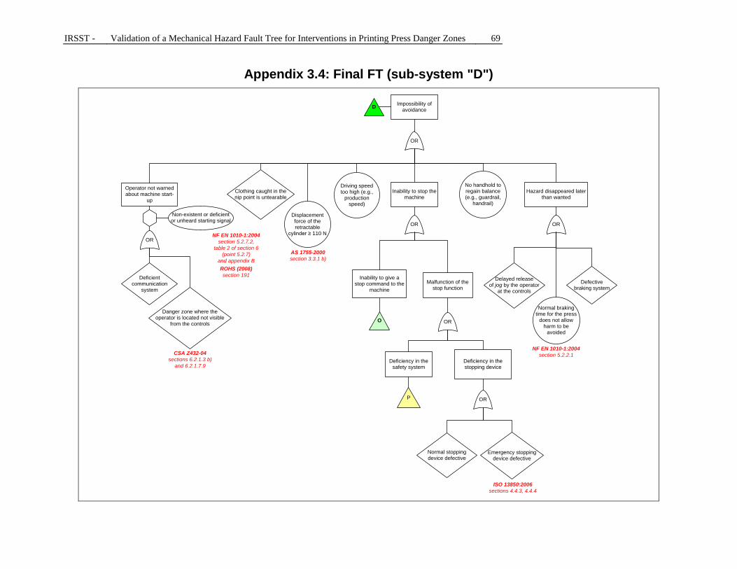
IRSST - Validation of a Mechanical Hazard Fault Tree for Interventions in Printing Press Danger Zones 69
Appendix 3.4: Final FT (sub-system "D")
D
Driving speedtoo high (e.g.,
production speed)
No handhold to regain balance (e.g., guardrail,
handrail)
Impossibility of avoidance
OR
Displacement force of the retractable
cylinder ≥ 110 N
Clothing caught in thenip point is untearable
O
Inability to stop the machine
OR
OR
Hazard disappeared later than wanted
OR
Defectivebraking system
Delayed releaseof jog by the operator
at the controls
AS 1755-2000section 3.3.1 b)
Malfunction of the stop function
Deficiency in the stopping device
Emergency stopping device defective
Normal stoppingdevice defective
Deficiency in the safety system
P OR
ISO 13850:2006sections 4.4.3, 4.4.4
Operator not warned about machine start-
up
OR
Danger zone where theoperator is located not visible
from the controls
Non-existent or deficient or unheard starting signal
CSA Z432-04sections 6.2.1.3 b)
and 6.2.1.7.9
NF EN 1010-1:2004section 5.2.7.2,
table 2 of section 6 (point 5.2.7)
and appendix BROHS (2008)section 191Deficient
communication system
Inability to give a stop command to the
machine
NF EN 1010-1:2004section 5.2.2.1
Normal braking time for the press
does not allow harm to be
avoided

70 Validation of a Mechanical Hazard Fault Tree for Interventions in Printing Press Danger Zones - IRSST
Appendix 3.5: Final FT (sub-system "E")
AND
G
Operator not warned about
machine start-up
OR
Deficient communication
system
Danger zone where the operator is located is not visible from the controls
E
1Start-up initiated by someone else without the operator’s knowledge (from this operator's work zone or
elsewhere on the press)
Non-existent or deficient or unheard starting signal
CSA Z432-04sections 6.2.1.3 b)
and 6.2.1.7.9Another operator
activates controls in the same unit
Another operatoractivates priority controls from
another work zone
A start-up command is given
ISO 14118-2000section 4.2,appendix B
NF EN 1010-1:2004section 5.2.3.3
ROHS (2008)section 191OR
Shared control activated
Operator not ensuring that the
press remains stopped
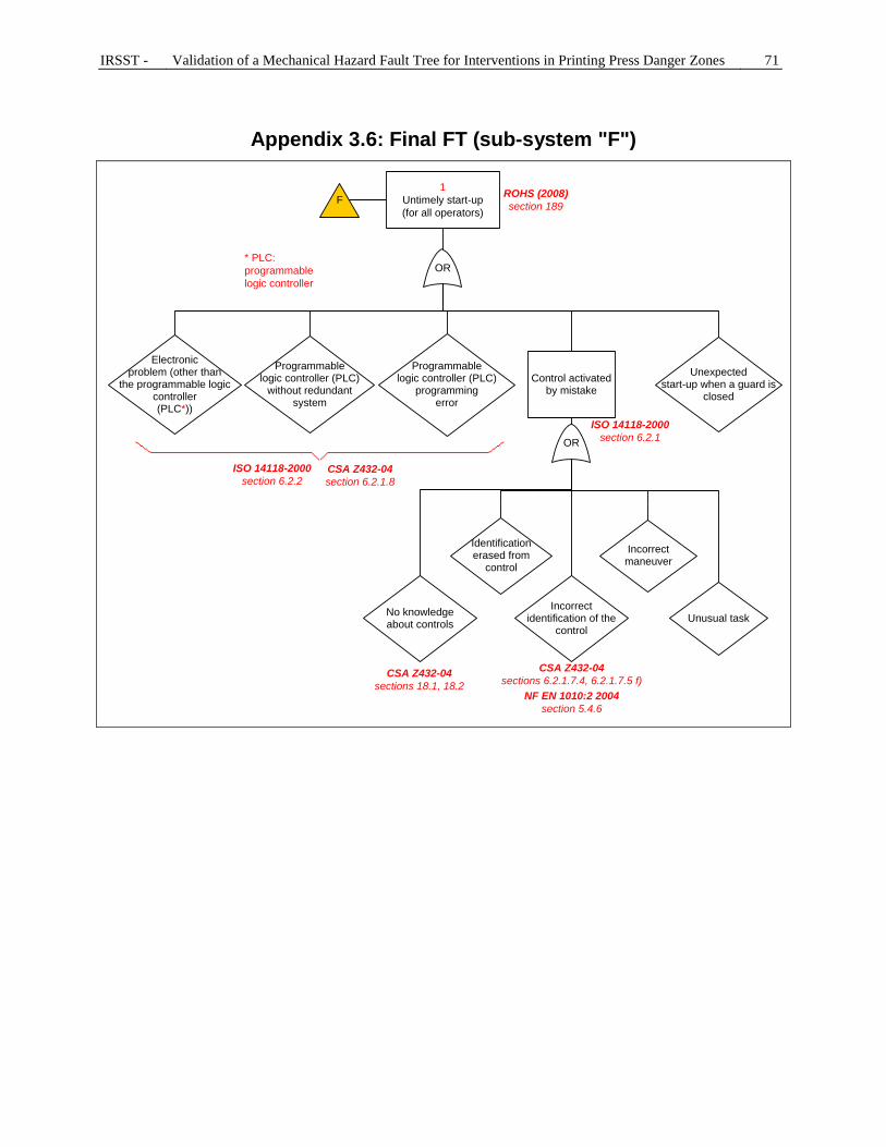
IRSST - Validation of a Mechanical Hazard Fault Tree for Interventions in Printing Press Danger Zones 71
Appendix 3.6: Final FT (sub-system "F")
OR
Control activated by mistake
OR
Unexpectedstart-up when a guard is
closed
Electronicproblem (other than
the programmable logic controller(PLC*))
Programmablelogic controller (PLC)
without redundantsystem
Programmablelogic controller (PLC)
programming error
Incorrect identification of the
control
Identificationerased from
control
F
Incorrect maneuver
1Untimely start-up(for all operators)
* PLC: programmable logic controller
CSA Z432-04sections 6.2.1.7.4, 6.2.1.7.5 f)
CSA Z432-04section 6.2.1.8
No knowledgeabout controls Unusual task
CSA Z432-04sections 18.1, 18.2
ISO 14118-2000section 6.2.1
ISO 14118-2000 section 6.2.2
NF EN 1010:2 2004section 5.4.6
ROHS (2008)section 189

72 Validation of a Mechanical Hazard Fault Tree for Interventions in Printing Press Danger Zones - IRSST
Appendix 3.7: Final FT (sub-system "G")
G
SAFE button not engaged
OR
Omitting to engage the SAFE button
Assigned person does not engage
the SAFE(communication
error)
SAFE button was disengaged following the intervention of another
operator
Emergency stop function not
activated
OR
Omitting to engage emergency stop button
Another assignedperson does not engage
the emergency stop button (communication
error)
The emergency stop button was deactivated
OR
No SAFE button Non-priority SAFE button engaged
OR
Defect in the control system associated with the
SAFE button
Other SAFEalready engaged on the
machine
ISO 13850:2006,section4.1.6
ISO 14118-2000section 6.3.4
ROHSsections 190, 192
NF EN 1010-1: 2004section 5.2.5.3 and table 2 of section 6
(point 5.2.5.3)
ANSI B65.1-2005section
11.2.3.1.1.1
No stop button or emergency stop
button
Work zone dependent on the remainder of the
press
OR
Electrical dependenceof motors
Mechanical dependence (non-disengagement)
Operator not ensuring that the
press remains stopped
Inaccessible stopbutton or emergency
stop buttonISO 13850:2006,section 3.1
Design deficiency
Emergency stop button deactivated/reset by another
operator

IRSST - Validation of a Mechanical Hazard Fault Tree for Interventions in Printing Press Danger Zones 73
Appendix 3.8: Final FT (sub-system "H")
OR
HROHS (2008)
section182
OR
Fixed guard not returned to its
location
No guard (e.g., unprotected nip
point)
OR
Frequent needto access the danger
zone
Time constraints
No guard
OR
Known but unprotected
nip point
Unknown nip point Heavy and/or
voluminous guard
Poorly designed guard
Guard/protective device not or
improperly attached
OR
Ineffective protection
OR
Vibration problem
Attachments do not comply with
design
I
Inappropriate retractable
cylinder
The protective device does not detect the presence of
a part of the body
Protective device improperly installed/
positioned
OR
Protective device bypassed
P
Deficiency in safety system
ISO 14119:1998,section 5.7
ANSI B65.1-2005,section 7.6.2.1
CSA Z432-04section 6.2.2
CSA Z432-04section 16
CSA Z432-04section
6.2.2.2.1.4, section 14.2.6
Nip point accessible
NF EN 1010-1:2004section 5.2.1.1
NF EN 1010-1: 2004sections 5.2.9, 5.2.10
and table 2 of section 6 (points 5.2.9 and 5.2.10)
NF EN 1010-1:2004section 6 (point
5.2.1.1 of table 2)
ROHS (2008)section 184
Deficient risk monitoring and management
Inspection failure
Inspection defect

74 Validation of a Mechanical Hazard Fault Tree for Interventions in Printing Press Danger Zones - IRSST
Appendix 3.9: Final FT (sub-system "I")
Movable guard open when the hazard is
occurring
Deficient safety system
Safety system bypassed
P
OR
Poorly designed guard
OR
Guard improperly installed in relation to
danger zone
Unsuitable material
OR
Worn material
OR
Openings do not comply with
standards (guard-opening safety scale)
Non-compliant dimensions of
the guard
Movable guard without safety
device
Unsuitable interlocking or guard locking device
Non-compliant distance between the guard and
the danger zone
OR
Fixed guard that can be removed without using a
tool
Device not adaptedto the workplace
Fragile material
Flexible material
Standards/regulations not
applied
Device not installed according to a positive
actuation mode
OR
System easily bypassed Other
I
OR
No knowledge/non-application of current standards
ANSI B65.1-2005,section 7.1.1.1
ANSI B65.1-2005,sections 7.1.1.2, 7.4
ISO 14119:1998,sections 3.1, 3.2, 3.3,
3.4, 4.2ISO 14119:1998,
section 5.7
ANSI B65.1-2005,section 7.1.2
ANSI B65.1-2005,sections 7.1.2.2,
7.1.6, 7.2, 7.3ANSI B65.1-2005,
section 7.1.6
CSA Z432-04section
6.2.3.2.2
CSA Z432-04section
6.2.3.1.2 a)
CSA Z432-04section 6.2.3.2.3CSA Z432-04
section 6.2.3.1.2 d)
CSA Z432-04section 6.2.3.1.2 c)
CSA Z432-04section 16CSA Z432-04
section 16
CSA Z432-04section 10.2.4
NF EN 1010-1:2004sections 5.2.2 ,5.3.2, 5.3.5
and table 2 of section 6, points 5.2.2.3, 5.2.2.6 and
5.3.2
ROHS (2008)section 174
ROHS (2008)sections 175 and 176
Deficientmonitoring and risk
managementInspection failure
Deficient monitoring and risk
management
I1
I1
I1
I1
I1

IRSST - Validation of a Mechanical Hazard Fault Tree for Interventions in Printing Press Danger Zones 75
Appendix 3.10: Final FT (sub-system "J")
J
Inappropriate personal protective equipment (PPE) or
clothing
OR
Use of anunsuitable tool/material
(e.g., frayed rag)
Unsafe use of an appropriate tool
Loose clothing Poorly fitting gloves
OR
Other
CSA Z432-04section18.3
Jewelry
ROHS (2008)section 340
Object held or carried (by the operator)
caught in a nip point
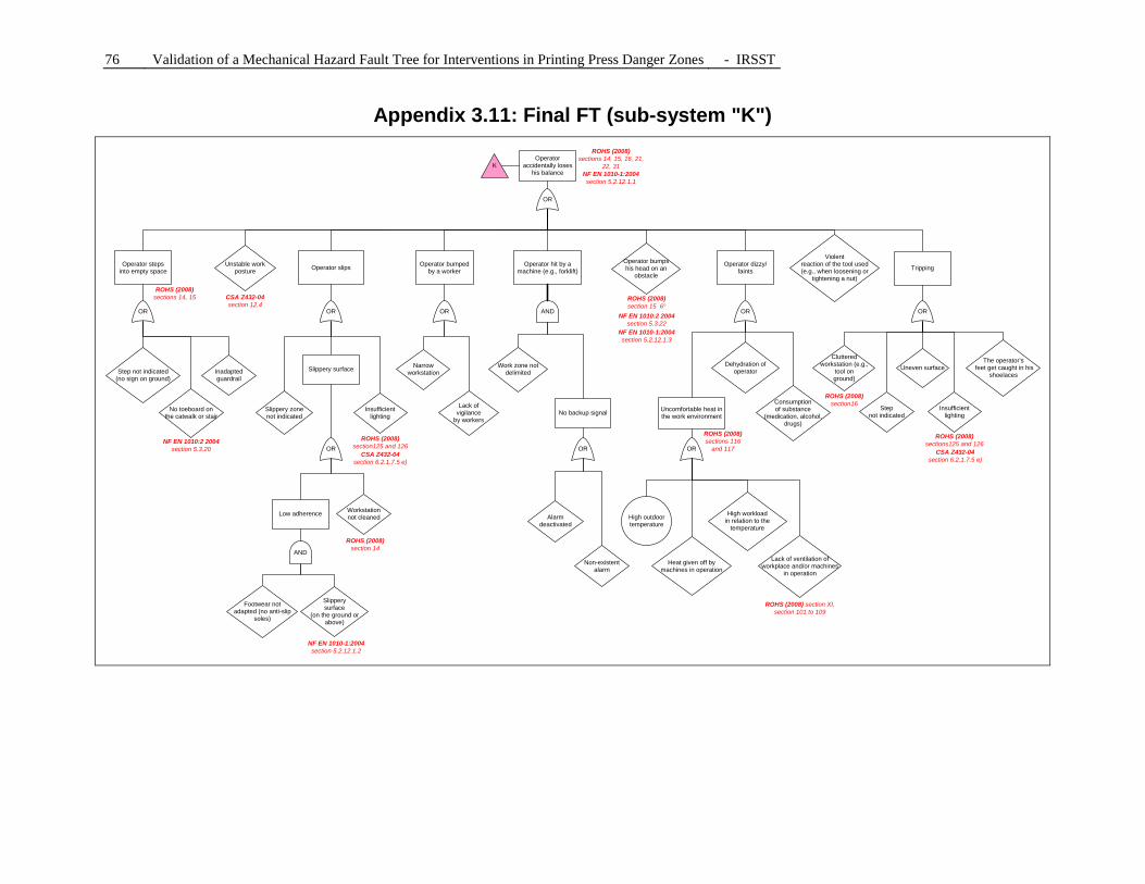
76 Validation of a Mechanical Hazard Fault Tree for Interventions in Printing Press Danger Zones - IRSST
Appendix 3.11: Final FT (sub-system "K")
Operator accidentally loses
his balance
OR
Operator dizzy/faints
Uncomfortable heat in the work environment
OR
Heat given off by machines in operation
High outdoor temperature
OR
Operator bumped by a worker
OR
Slippery surface
K
Low adherence
Operator steps into empty space
OR
AND
Tripping
OR
Operator slips
OR OR
Dehydration of operatorInadapted
guardrail
No toeboard onthe catwalk or stair
Step not indicated(no sign on ground)
Footwear notadapted (no anti-slip
soles)
Slipperysurface
(on the ground or above)
Workstationnot cleaned
Slippery zonenot indicated
Lack ofvigilance
by workers
Lack of ventilation of workplace and/or machines
in operation
Consumptionof substance
(medication, alcohol, drugs)
The operator’s feet get caught in his
shoelaces
Cluttered workstation (e.g.,
tool onground)
Step not indicated
Uneven surface
Violentreaction of the tool used(e.g., when loosening or
tightening a nut)
Insufficient lighting
Insufficient lighting
Narrow workstation
ROHS (2008) section XI, section 101 to 109
ROHS (2008) sections 116
and 117ROHS (2008)
section125 and 126ROHS (2008)
sections125 and 126
Operator bumpshis head on an
obstacle
ROHS (2008)section 15 6°
ROHS (2008)section 14
ROHS (2008)sections 14, 15
ROHS (2008)sections 14, 15, 16, 21,
22, 31
Unstable work posture
CSA Z432-04section 12.4
Operator hit by a machine (e.g., forklift)
No backup signal
OR
Alarmdeactivated
Non-existent alarm
AND
Work zone not delimited
NF EN 1010-1:2004section 5.2.12.1.2
NF EN 1010-1:2004section 5.2.12.1.3
ROHS (2008)section16
NF EN 1010-1:2004section 5.2.12.1.1
NF EN 1010:2 2004section 5.3.20
NF EN 1010:2 2004section 5.3.22
CSA Z432-04section 6.2.1.7.5 e)
CSA Z432-04section 6.2.1.7.5 e)
High workloadin relation to the
temperature

IRSST - Validation of a Mechanical Hazard Fault Tree for Interventions in Printing Press Danger Zones 77
Appendix 3.12: Final FT (sub-system "L")
Decreased vigilance
Fatigue
OR
OR
Monotony of the work
OR
L
Stress
Substanceconsumed that decreases
vigilance (medication, alcohol, drugs)
Prolongedobservation of a
productionprocess
Repetitive work
No rotation between the
workersHeat
Sound nuisance
Night work Pressure dueto competition
Imprecise taskto be performed
Deficientplanning of work
Major workload or responsibilities
Interruptions in operator’s work
Constraints relatedto the work environment
(noise, dust, temperature, odours, grime)
Operator’s inexperience
Teamwork constraints
OR
Variableschedule (day,
evening,night)
Insufficient breaks
Distraction by another person
ROHS (2008)section XV-BRUIT
ROHS (2008)section XIII
ROHS (2008)section 130
CSA Z432-04section 6.2.3.5.4.2
NF EN 1010-1:2004section 5.2.15 and table 2 of section 6 (point 5.2.15)
NF EN 1010:2 2004section 5.4.20
ANSI B65.1-2005section 8.6
ANSI B65.1-2005section 8.6

78 Validation of a Mechanical Hazard Fault Tree for Interventions in Printing Press Danger Zones - IRSST
Appendix 3.13: Final FT (sub-system "M")
OR
M
Insufficient light
Danger zone is hidden from
operator’s view (design)
ROHS (2008)sections 125
and 126
CSA Z432-04sections 6.2.1.3 b)
and 6.2.1.7.9,section 12.5
NF EN 1010-1:2004section 5.2.3.3,
table 2 of section 6 (point 5.2.3.3)
Nip point hardly or not visible
CSA Z432-04section 6.2.1.7.5 e),
section 12.5
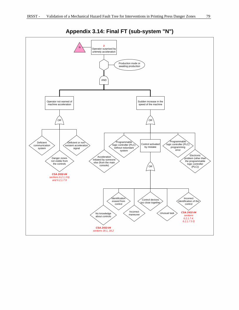
IRSST - Validation of a Mechanical Hazard Fault Tree for Interventions in Printing Press Danger Zones 79
Appendix 3.14: Final FT (sub-system "N")
2Operator surprised by untimely acceleration
N
Operator not warned of machine acceleration
OR
Danger zones not visible from
the controls
Deficient or non-existent acceleration
signal
AND
Sudden increase in the speed of the machine
Control activated by mistake
OR
Unusual task
Electronicproblem (other thanthe programmable
logic controller(PLC))
Programmablelogic controller (PLC)
programmingerror
OR
CSA Z432-04sections 6.2.1.3 b)
and 6.2.1.7.9
Incorrect maneuver
CSA Z432-04sections 18.1, 18.2
Incorrect identification of the
control
Identificationerased from
control
Control devicestoo close together
Deficient communication
system
Accelerationinitiated by someoneelse (from the main
console)
Programmablelogic controller (PLC)
without redundantsystem
Production mode or awaiting production
No knowledgeabout controls
CSA Z432-04sections 6.2.1.7.4,
6.2.1.7.5 f)
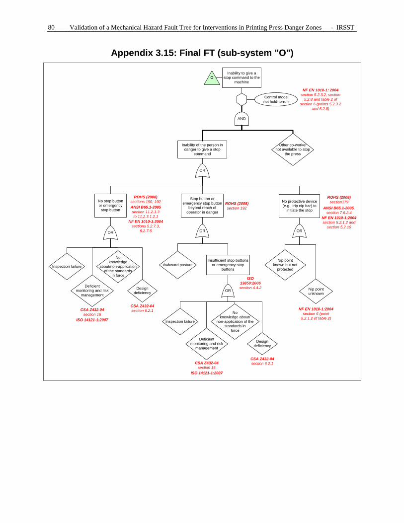
80 Validation of a Mechanical Hazard Fault Tree for Interventions in Printing Press Danger Zones - IRSST
Appendix 3.15: Final FT (sub-system "O")
No stop button or emergency
stop button
Stop button or emergency stop button
beyond reach of operator in danger
O
Control modenot hold-to-run
OR
Noknowledge
about/non-application of the standards
in force
Design deficiency
OR
OR
Deficientmonitoring and risk
management
Inspection failure
Design deficiency
Awkward posture
ROHS (2008)sections 190, 192 ROHS (2008)
section 192
AND
OR
Inability of the person in danger to give a stop
command
Other co-workernot available to stop
the press
ISO 13850:2006section 4.4.2
CSA Z432-04section 6.2.1
Insufficient stop buttons or emergency stop
buttons
NF EN 1010-1: 2004section 5.2.3.2, section
5.2.8 and table 2 of section 6 (points 5.2.3.2
and 5.2.8)
NF EN 1010-1:2004sections 5.2.7.3,
5.2.7.6
ANSI B65.1-2005section 11.2.1.3 to 11.2.3.1.2.1
Deficientmonitoring and risk
management
Inspection failure
Noknowledge about/
non-application of the standards in
force
No protective device (e.g., trip nip bar) to
initiate the stop
OR
ANSI B65.1-2005,section 7.6.2.4
NF EN 1010-1:2004section 6 (point
5.2.1.2 of table 2)
ROHS (2008)section179
NF EN 1010-1:2004section 5.2.1.2 and
section 5.2.10
Nip pointknown but not
protected
Nip point unknown
Inability to give a stop command to the
machine
CSA Z432-04section 16
ISO 14121-1:2007
CSA Z432-04section 6.2.1CSA Z432-04
section 16ISO 14121-1:2007

IRSST - Validation of a Mechanical Hazard Fault Tree for Interventions in Printing Press Danger Zones 81
Appendix 3.16: Final FT (sub-system "P")
Deficient safety system
OR
Programmablelogic controller (PLC)
programmingerror
Safetydevice not adapted to
the workplace
Excessivewear on thecontroller
device
Grippingof controller device
(push-button)
Malfunction(e.g., trip nip bar)
Incorrectlyinstalled safety
devices
Defectivedevices (interlocking or
guard locking device) without positive mechanical action
or positive openingcontacts
Defective wiring
PoorlyInstalledwiring
P
Poorly designed safety device
ISO 14119:1998,chap. 7
NF EN 1010-1:2004section 5.2.6.1 and table 2 of section 6
(point 5.2.6)
CSA Z432-04section 6.2.1.8
Programmablelogic controller (PLC)
without redundantsystem

82 Validation of a Mechanical Hazard Fault Tree for Interventions in Printing Press Danger Zones - IRSST
APPENDIX 4: MEETINGS WITH ASP IMPRIMERIE
First meeting
In the first validation meeting for the fault tree with two prevention advisors from ASP imprimerie, the research team wanted to:
1. Demonstrate to the ASP representatives the evolution in the fault tree up to that date; 2. Explain to the advisors the general evolution in the fault tree since its original version; 3. Ensure that the content of the cells is easily understandable by press operators; 4. Ensure that the causes mentioned in the different levels of the fault tree are correct and
plausible; 5. Ensure that the gates linking the causes are correct; 6. Ensure that the fault tree obtained satisfies the advisors of ASP imprimerie.
All the points were considered and the six objectives were reached. The ASP advisors were satisfied with the evolution in the fault tree up to that date. Modifications were proposed, such as: reformulating the content of the cells in order to make the fault tree easier to understand, adding and removing causes, and moving causes from one level to another to be more consistent with the logical reading order of the fault tree. Second meeting
At the time of this second meeting between the research team and two prevention advisors from ASP imprimerie, the visits were conducted. However, despite the information gathered from the press operators during the visits, three points still required improvement. With this 2nd validation meeting, the research team wanted to:
1. Present to the representatives of ASP imprimerie the fault tree corrected following the 1st validation meeting and the seven printing company visits;
2. Clarify the three problematic points below: a. The combinations of causes related to the inability to stop the machine in the
context of an impossibility of avoidance (sub-system "D"), b. The reasons why a nip point can be accessible (sub-system "H"), c. All the causes relating to unexpected start-up (sub-system "E") and with an
untimely acceleration (sub-system "N"). 3. Ensure the accuracy of the combinations of causes of the portions of the FT dealing with
the operation of the start-up, acceleration and stopping controls; 4. Verify again points 3 to 6 mentioned during the first meeting.
Generally, the objectives of the meeting were achieved, except for the accuracy of the portions of the fault tree dealing with printing press control. Consequently, it was agreed that these questions would be clarified during the validation meeting planned with the participants questioned during the visits.

IRSST - Validation of a Mechanical Hazard Fault Tree for Interventions in Printing Press Danger Zones 83
Third meeting
A validation meeting with the participants met during our visits (press operators, foremen) had been planned in the framework of the project. The goal of this meeting was to validate the logic and thoroughness of the fault tree and to obtain answers to our questions about the operation of the start-up, acceleration and stopping controls of printing presses. However, only one participant met during our visits was able to answer the invitation, but his contribution was very beneficial. While the objective was not achieved in terms of participation, this meeting enabled us to improve the fault tree to make it easier to understand. To do this, the press operators and the general manager of ASP imprimerie suggested that the content of certain cells be reformulated. These individuals also reflected on the logic of the combinations of causes mentioned in the fault tree and the reason for these causes. This reflection resulted in some causes being repositioned, others being added, and causes being eliminated when they did not apply to the context. It was at this meeting that the team obtained clear and accurate responses about the operation of the start-up, acceleration and stopping controls. Corrections were made to the FT as a consequence. Fourth meeting
The fourth validation meeting involved a complete and final review of the FT by the four prevention advisors from ASP imprimerie. For reasons of simplification and precision, these advisors made a few minor comments about the formulation of certain causes. These comments, like the comments agreed on during the previous meetings, were taken into consideration in the final version of the FT. During this meeting, a document detailing and justifying the evolution in the FT from its original version was submitted as explanatory comments.