validated reference design guide deploying a 2 tier …...the aos-cx switches to be deployed will...
TRANSCRIPT

VALIDATED REFERENCE DESIGN GUIDE
DEPLOYING A 2 TIER DC NETWORK WITH NETEDIT
CONTENTS Introduction ....................................................................................................................................................................................................... 3 1) Initial Setup (OOB, Initial Configs) ................................................................................................................................................................. 5
Sample Initial Configuration .................................................................................................................................................................. 6 2) Modify Change Validation Settings ................................................................................................................................................................ 7 3) 2 Tier DC POD/Zone Configuration and Verification ..................................................................................................................................... 9
NetEdit Plan For “Zone1-Access” Switches ........................................................................................................................................... 9 Verify Change Validation ..................................................................................................................................................................... 19 NetEdit Plan For “Zone1-Core” Switches ............................................................................................................................................ 21 Verify Change Validation ..................................................................................................................................................................... 31
4) DC-Core Configuration and Verification ...................................................................................................................................................... 35 DC-Core1 Configuration and Verification ............................................................................................................................................ 35
Appendix .......................................................................................................................................................................................................... 37 Sample Core Configuration ................................................................................................................................................................. 37 Sample Access Configuration .............................................................................................................................................................. 39

VALIDATED REFERENCE DESIGN GUIDE DEPLOYING A 2 TIER DC NETWORK WITH NETEDIT
© Copyright 2019 Hewlett Packard Enterprise Development LP
Notices The information contained herein is subject to change without notice. The only warranties for Hewlett Packard Enterprise products and services are set forth in the express warranty statements accompanying such products and services. Nothing herein should be construed as constituting an additional warranty. Hewlett Packard Enterprise shall not be liable for technical or editorial errors or omissions contained herein. Confidential computer software. Valid license from Hewlett Packard Enterprise required for possession, use, or copying. Consistent with FAR 12.211 and 12.212, Commercial Computer Software, Computer Software Documentation, and Technical Data for Commercial Items are licensed to the U.S. Government under vendor's standard commercial license. Links to third-party websites take you outside the Hewlett Packard Enterprise website. Hewlett Packard Enterprise has no control over and is not responsible for information outside the Hewlett Packard Enterprise website.

VALIDATED REFERENCE DESIGN GUIDE DEPLOYING A 2 TIER DC NETWORK WITH NETEDIT
INTRODUCTION
This document provides guidance on deploying an AOS-CX powered 2 Tier Data Center (DC) network with NetEdit.
The AOS-CX switches to be deployed will depend on interfaces, scale and features required. Aruba networks provides a diverse product portfolio to meet different customer requirements.
NetEdit empowers IT teams to orchestrate multiple switch configurations with intelligent capabilities including search, edit, validation (including conformance checking), deployment and audit. Using NetEdit, the network admin can configure and validate multiple switches simultaneously, while specifying unique settings for each switch.
The 2 Tier DC POD/Zone architecture as shown in Figure 1 provides the following benefits: • Distributed scaled out control planes and increased port density compared to DC Collapsed Core • Are very common and simple solutions to deploy, operate and troubleshoot • Provides maximum network High Availability and uptime with VSX Live Upgrades • Provides built in support for Network Analytics Engine • Loop free L2 network fabric • Provides optimized East-West L2/L3 connectivity between racks with all links active
The 2 Tier DC POD/Zone architecture can be replicated to other PODs/Zones to create separate failure domains. A L3 DC core will connect all the zones together, each POD/Zone is assigned its own AS# and EBGP is recommended as the routing protocol to route traffic between the PODs/Zones. The POD/Zone architecture enables each POD/Zone to have different architectures if desired, e.g. Zone12 requires a L3 Spine/Leaf fabric with VXLAN/EVPN while Zone1 only requires a 2 Tier DC architecture.
Figure 1. POD/Zone DC architecture
The IP address assignments and interface details used in this guide are shown in Figure 2.
For the sake of completeness, configs for the L3 DC Core are also included to show the routes learnt from the 2 Tier DC POD/Zone.
In the DC core switches: • aspath-lists are used to allow desired routes from each POD/Zone, in this example “_65001$” refers to routes that
originate from AS65001 • prefix-list are used to advertise allow the default route towards compute PODs/Zones
VALIDATED REFERENCE DESIGN GUIDE DEPLOYING A 2 TIER DC NETWORK WITH NETEDIT
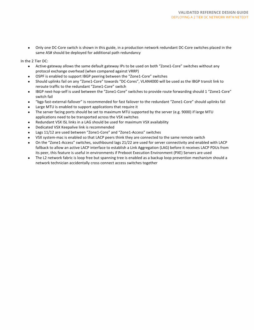
• Only one DC-Core switch is shown in this guide, in a production network redundant DC-Core switches placed in the same AS# should be deployed for additional path redundancy
In the 2 Tier DC: • Active-gateway allows the same default gateway IPs to be used on both “Zone1-Core” switches without any
protocol exchange overhead (when compared against VRRP) • OSPF is enabled to support IBGP peering between the “Zone1-Core” switches • Should uplinks fail on any “Zone1-Core” towards “DC-Cores”, VLAN4000 will be used as the IBGP transit link to
reroute traffic to the redundant “Zone1-Core” switch • IBGP next-hop-self is used between the “Zone1-Core” switches to provide route forwarding should 1 “Zone1-Core”
switch fail • “bgp fast-external-fallover” is recommended for fast failover to the redundant “Zone1-Core” should uplinks fail • Large MTU is enabled to support applications that require it • The server facing ports should be set to maximum MTU supported by the server (e.g. 9000) if large MTU
applications need to be transported across the VSX switches • Redundant VSX ISL links in a LAG should be used for maximum VSX availability • Dedicated VSX Keepalive link is recommended • Lags 11/12 are used between “Zone1-Core” and “Zone1-Access” switches • VSX system-mac is enabled so that LACP peers think they are connected to the same remote switch • On the “Zone1-Access” switches, southbound lags 21/22 are used for server connectivity and enabled with LACP
fallback to allow an active LACP interface to establish a Link Aggregation (LAG) before it receives LACP PDUs from its peer, this feature is useful in environments if Preboot Execution Environment (PXE) Servers are used
• The L2 network fabric is loop free but spanning tree is enabled as a backup loop prevention mechanism should a network technician accidentally cross connect access switches together

VALIDATED REFERENCE DESIGN GUIDE DEPLOYING A 2 TIER DC NETWORK WITH NETEDIT
Figure 2. Interface and IP address details
1) INITIAL SETUP (OOB, INITIAL CONFIGS)
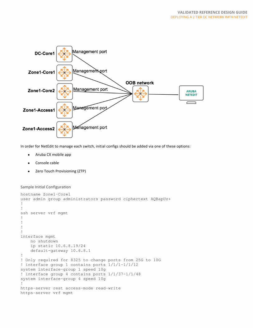
In the DC, we recommend switches connect their management ports to a separate Out Of Band (OOB) management network as shown in Figure 3, this allows the switches to be manageable if there is an issue with In Band network connectivity.
Figure 3. OOB connectivity
VALIDATED REFERENCE DESIGN GUIDE DEPLOYING A 2 TIER DC NETWORK WITH NETEDIT
In order for NetEdit to manage each switch, initial configs should be added via one of these options:
• Aruba CX mobile app
• Console cable
• Zero Touch Provisioning (ZTP)
Sample Initial Configuration
hostname Zone1-Core1 user admin group administrators password ciphertext AQBapUz+ ! ! ssh server vrf mgmt ! ! ! ! interface mgmt no shutdown ip static 10.6.8.19/24 default-gateway 10.6.8.1 ! ! Only required for 8325 to change ports from 25G to 10G ! interface group 1 contains ports 1/1/1-1/1/12 system interface-group 1 speed 10g ! interface group 4 contains ports 1/1/37-1/1/48 system interface-group 4 speed 10g ! https-server rest access-mode read-write https-server vrf mgmt

VALIDATED REFERENCE DESIGN GUIDE DEPLOYING A 2 TIER DC NETWORK WITH NETEDIT
Once the switches are configured and physically connected, ensure NetEdit has IP connectivity to switch management IPs and add all devices into NetEdit [Devices -> Action -> Add Device(s) or Add Multiple Devices]
2) MODIFY CHANGE VALIDATION SETTINGS
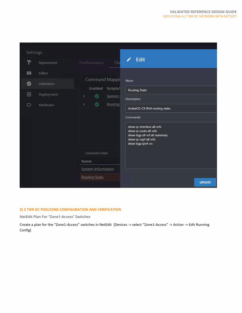
To help with change validation, you can add or modify the change validation commands used by NetEdit.
This is done in NetEdit [Settings -> Validation -> Change Validation -> Command Scripts]
The screenshots below showcase the verification commands used in this guide.

VALIDATED REFERENCE DESIGN GUIDE DEPLOYING A 2 TIER DC NETWORK WITH NETEDIT
VALIDATED REFERENCE DESIGN GUIDE DEPLOYING A 2 TIER DC NETWORK WITH NETEDIT
3) 2 TIER DC POD/ZONE CONFIGURATION AND VERIFICATION
NetEdit Plan For “Zone1-Access” Switches
Create a plan for the “Zone1-Access” switches in NetEdit [Devices -> select “Zone1-Access” -> Action -> Edit Running Config]

VALIDATED REFERENCE DESIGN GUIDE DEPLOYING A 2 TIER DC NETWORK WITH NETEDIT
Give the plan a name and “Create”.
You should see the initial configs for your “Zone1-Access” switches in NetEdit.
The common configs across the switches are shown as “white” while the “blue” variables such as “HOSTNAME” and “A.B.C.D/M” have unique settings/values.

VALIDATED REFERENCE DESIGN GUIDE DEPLOYING A 2 TIER DC NETWORK WITH NETEDIT
If you hover over “HOSTNAME” or “A.B.C.D/M” config (in blue), you can view the unique settings assigned to each switch.

VALIDATED REFERENCE DESIGN GUIDE DEPLOYING A 2 TIER DC NETWORK WITH NETEDIT
If you right click “HOSTNAME” or “A.B.C.D/M” (in blue), you will be able to modify the settings.
Start by selecting a pair of access switches and add VSX KeepAlive (KA)
interface 1/1/47 no shutdown description VSX KA ip address 10.1.2.3/31

VALIDATED REFERENCE DESIGN GUIDE DEPLOYING A 2 TIER DC NETWORK WITH NETEDIT
And right click to modify IPs assigned to each switch
After the specific values are modified, the IP values will be saved in the plan
Add VSX ISL LAG
interface lag 1 no shutdown description VSX ISL LAG no routing vlan trunk native 1 tag vlan trunk allowed all lacp mode active ! interface 1/1/48 no shutdown mtu 9198 description VSX ISL lag 1

VALIDATED REFERENCE DESIGN GUIDE DEPLOYING A 2 TIER DC NETWORK WITH NETEDIT
Add VSX
vsx system-mac 00:00:00:00:02:11 inter-switch-link lag 1 role primary keepalive peer 10.1.2.3 source 10.1.2.2
VALIDATED REFERENCE DESIGN GUIDE DEPLOYING A 2 TIER DC NETWORK WITH NETEDIT
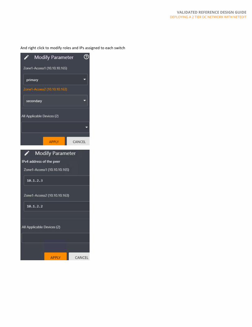
And right click to modify roles and IPs assigned to each switch

VALIDATED REFERENCE DESIGN GUIDE DEPLOYING A 2 TIER DC NETWORK WITH NETEDIT
After the specific values are modified, these should be updated
Add VLANs and Spanning Tree
vlan 11-12 spanning-tree spanning-tree config-name Zone1 spanning-tree config-revision 1 spanning-tree instance 1 vlan 11,12
Add northbound VSX LAGs to “Zone1-Core” switches and southbound VSX LAGs to “Servers”
interface lag 11 multi-chassis no shutdown description Zone1-Cores no routing vlan trunk native 1 vlan trunk allowed 11-12 lacp mode active interface lag 21 multi-chassis no shutdown description Server no routing vlan trunk native 1 vlan trunk allowed 11-12 lacp mode active lacp fallback spanning-tree port-type admin-edge interface 1/1/49 no shutdown mtu 9198 description Zone1-Cores lag 11 interface 1/1/50
VALIDATED REFERENCE DESIGN GUIDE DEPLOYING A 2 TIER DC NETWORK WITH NETEDIT
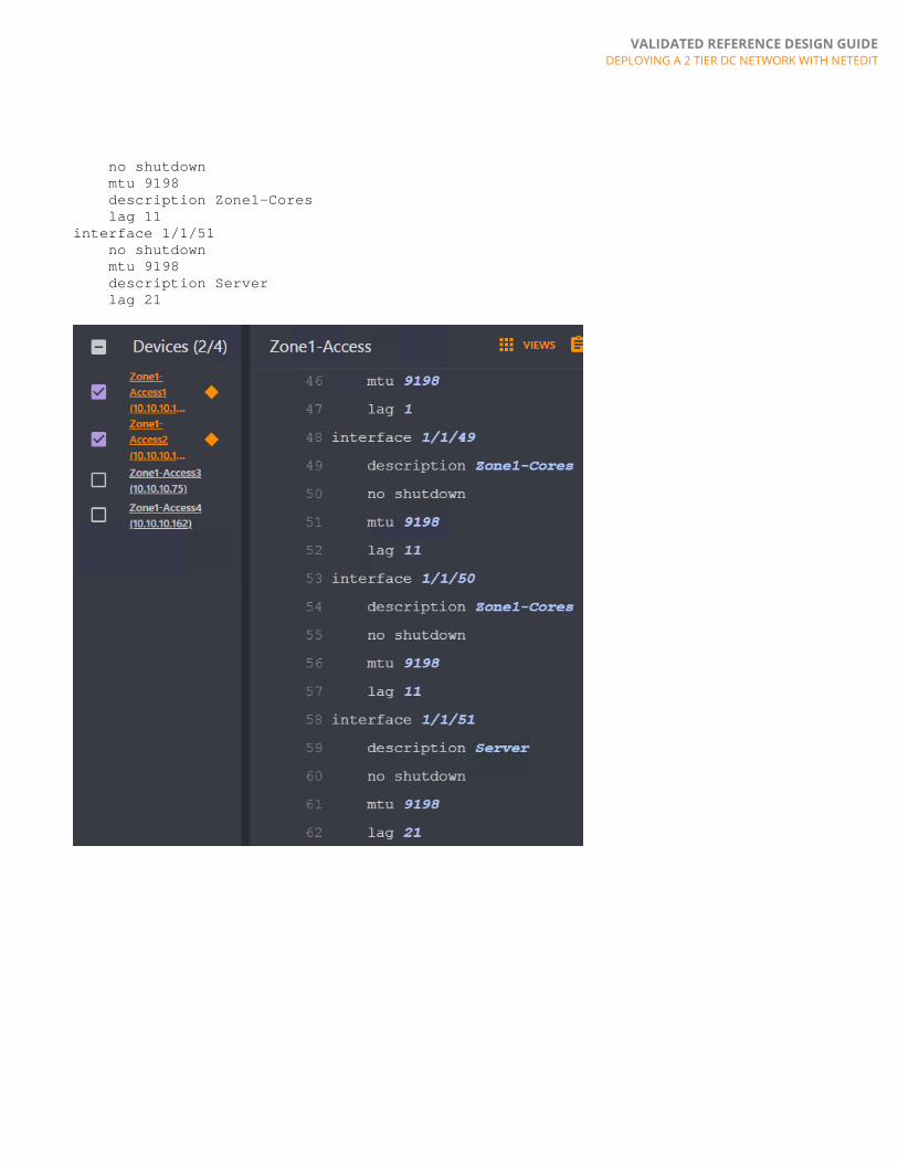
no shutdown mtu 9198 description Zone1-Cores lag 11 interface 1/1/51 no shutdown mtu 9198 description Server lag 21

VALIDATED REFERENCE DESIGN GUIDE DEPLOYING A 2 TIER DC NETWORK WITH NETEDIT
Select other access switch pairs and repeat the above steps (e.g. VSX IS -> VSX -> VLANs -> Spanning Tree -> Northbound and Southbound VSX LAGs
This is an example showing all access switches configured

VALIDATED REFERENCE DESIGN GUIDE DEPLOYING A 2 TIER DC NETWORK WITH NETEDIT
Once all access switch configurations are complete, select “RETURN TO PLAN” -> “DEPLOY” to push down configs.
Verify Change Validation
You can click on “Change Validation” to verify if VSX works as expected.

VALIDATED REFERENCE DESIGN GUIDE DEPLOYING A 2 TIER DC NETWORK WITH NETEDIT
Check if VSX LAGs to servers are up as expected (if servers are connected)
After validation, you can choose to “COMMIT” to save the desired configs or “ROLLBACK” to revert configs before the configs were deployed to make further desired changes.

VALIDATED REFERENCE DESIGN GUIDE DEPLOYING A 2 TIER DC NETWORK WITH NETEDIT
NetEdit Plan For “Zone1-Core” Switches
Create a plan for the “Zone1-Core” switches in NetEdit [Devices -> select “Zone1-Core” -> Action -> Edit Running Config]
Give the plan a name and “Create”.
Start by adding VSX KeepAlive (KA)
interface 1/1/29 no shutdown description VSX KA ip address 10.1.2.0/31

VALIDATED REFERENCE DESIGN GUIDE DEPLOYING A 2 TIER DC NETWORK WITH NETEDIT
And right click to modify IPs assigned to each switch

VALIDATED REFERENCE DESIGN GUIDE DEPLOYING A 2 TIER DC NETWORK WITH NETEDIT
Add VSX ISL
interface lag 1 no shutdown description VSX ISL LAG no routing vlan trunk native 1 tag vlan trunk allowed all lacp mode active interface 1/1/31 no shutdown mtu 9198 description VSX ISL lag 1
Add VSX
vsx system-mac 00:00:00:00:01:01 inter-switch-link lag 1 role primary keepalive peer 10.1.2.1 source 10.1.2.0

VALIDATED REFERENCE DESIGN GUIDE DEPLOYING A 2 TIER DC NETWORK WITH NETEDIT
And right click to modify roles and IPs assigned to each switch

VALIDATED REFERENCE DESIGN GUIDE DEPLOYING A 2 TIER DC NETWORK WITH NETEDIT
After the specific values are modified, these should be updated
Add OSPF and loopbacks
router ospf 1 router-id 192.168.1.1 area 0.0.0.0 interface loopback 0 ip address 192.168.1.1/32 ip ospf 1 area 0.0.0.0
And right click to modify loopbacks and router-ids assigned to each switch
Configure uplinks towards DC-Core switches
interface 1/1/5 no shutdown

VALIDATED REFERENCE DESIGN GUIDE DEPLOYING A 2 TIER DC NETWORK WITH NETEDIT
description DC-Core1 ip address 10.1.1.0/31
And right click to modify IPs assigned to each switch
Add VLANs and configure IBGP transit VLAN between “Zone1-Core” switches
vlan 11-12,4000 ! interface vlan4000 description IBGP transit ip mtu 9198 ip address 10.1.2.2/31 ip ospf 1 area 0.0.0.0 ip ospf network point-to-point
And right click to modify IPs assigned to each switch
Configure EBGP towards “DC-Core” switches and IBGP between “Zone1-Core” switches, advertise the server subnets for connectivity out of the POD/Zone. Utilize route summarization if possible to minimize the subnets advertised out by each POD/Zone.
router bgp 65001 bgp router-id 192.168.1.1

VALIDATED REFERENCE DESIGN GUIDE DEPLOYING A 2 TIER DC NETWORK WITH NETEDIT
bgp fast-external-fallover neighbor 10.1.1.1 remote-as 65100 neighbor 192.168.1.2 remote-as 65001 neighbor 192.168.1.2 update-source loopback 0 address-family ipv4 unicast neighbor 10.1.1.1 activate neighbor 192.168.1.2 activate neighbor 192.168.1.2 next-hop-self network 11.1.1.0/24 network 12.1.1.0/24 And right click to modify IPs assigned to each switch.
If a config only exists in 1 switch, it will be stated on the right e.g. Zone1-Core1 or Zone1-Core2
Configure spanning tree
spanning-tree spanning-tree priority 0

VALIDATED REFERENCE DESIGN GUIDE DEPLOYING A 2 TIER DC NETWORK WITH NETEDIT
spanning-tree config-name Zone1 spanning-tree config-revision 1 spanning-tree instance 1 vlan 11,12
Configure links and LAGs towards “Zone1-Access” switches
interface lag 11 multi-chassis no shutdown description Zone1-Access1/2 no routing vlan trunk native 1 vlan trunk allowed 11-12 lacp mode active interface lag 12 multi-chassis no shutdown description Zone1-Access3/4 no routing vlan trunk native 1 vlan trunk allowed 11-12 lacp mode active interface 1/1/1 no shutdown mtu 9198 description Zone1-Access1 lag 11 interface 1/1/2 no shutdown mtu 9198 description Zone1-Access2 lag 11 interface 1/1/3 no shutdown mtu 9198 description Zone1-Access3 lag 12 interface 1/1/4

VALIDATED REFERENCE DESIGN GUIDE DEPLOYING A 2 TIER DC NETWORK WITH NETEDIT
no shutdown mtu 9198 description Zone1-Access4 lag 12
Add Switched Virtual Interfaces (SVIs) and Active Gateway IPs for the server subnets
interface vlan11 ip mtu 9198 ip address 11.1.1.2/24 active-gateway ip 11.1.1.1 mac 00:00:00:00:01:01 interface vlan12 ip mtu 9198 ip address 12.1.1.2/24 active-gateway ip 12.1.1.1 mac 00:00:00:00:01:01

VALIDATED REFERENCE DESIGN GUIDE DEPLOYING A 2 TIER DC NETWORK WITH NETEDIT
And right click to modify unique IPs assigned to each SVI
Finally, select “RETURN TO PLAN” -> “DEPLOY” to push down configs.

VALIDATED REFERENCE DESIGN GUIDE DEPLOYING A 2 TIER DC NETWORK WITH NETEDIT
Verify Change Validation
You can click on “Change Validation” to verify if VSX works as expected.
Check if BGP peers are up as expected

VALIDATED REFERENCE DESIGN GUIDE DEPLOYING A 2 TIER DC NETWORK WITH NETEDIT
Check if routing works as expected, the default route from “DC-Core” switches should be seen
Check LLDP neighbor changes

VALIDATED REFERENCE DESIGN GUIDE DEPLOYING A 2 TIER DC NETWORK WITH NETEDIT
Check VSX LAG changes
Check spanning tree forwarding

VALIDATED REFERENCE DESIGN GUIDE DEPLOYING A 2 TIER DC NETWORK WITH NETEDIT
And to validate config changes.
After validation, you can choose to “COMMIT” to save the desired configs or “ROLLBACK” to revert configs before the configs were deployed to make further desired changes.

VALIDATED REFERENCE DESIGN GUIDE DEPLOYING A 2 TIER DC NETWORK WITH NETEDIT
4) DC-CORE CONFIGURATION AND VERIFICATION
DC-Core1 Configuration and Verification
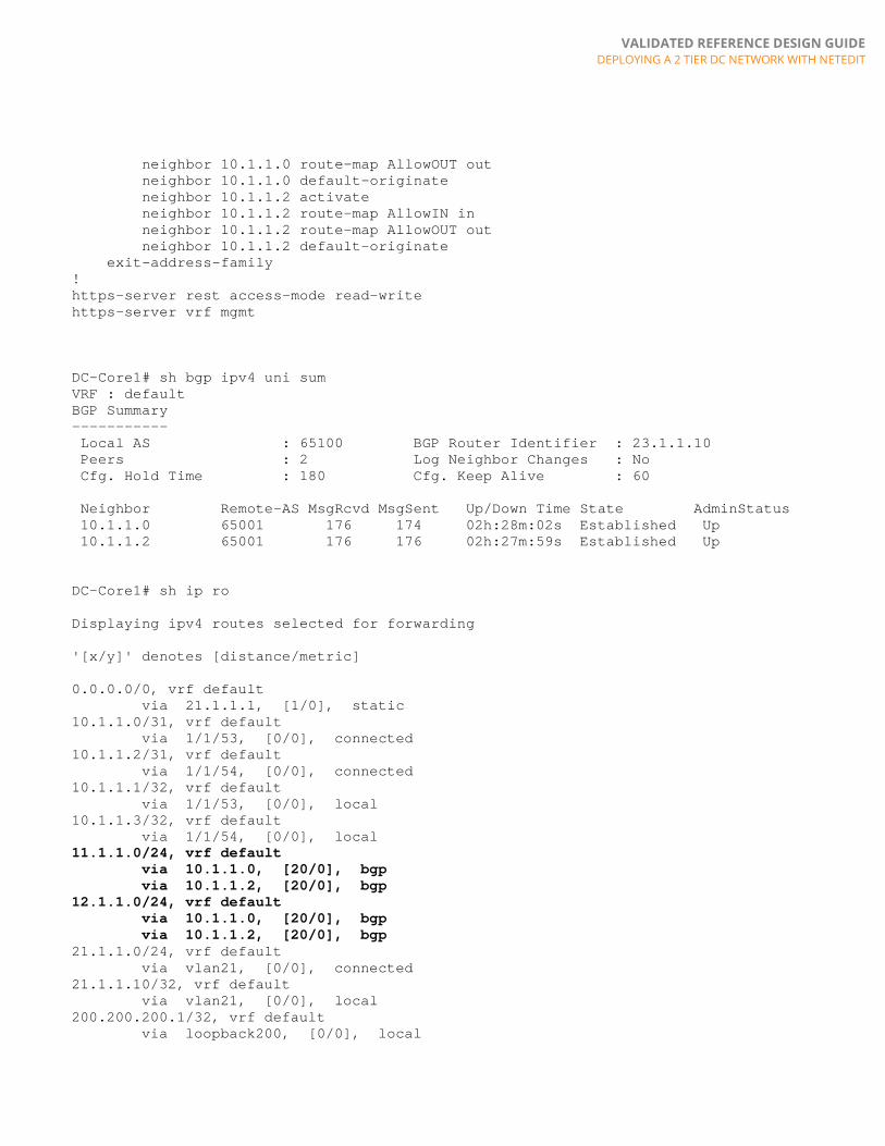
For the sake of completeness, configs for the L3 DC-Core1 are also included to show the routes learnt from the 2 Tier DC POD/Zone.
DC-Core1# sh run Current configuration: ! !Version ArubaOS-CX GL.10.03.0040 hostname DC-Core1 user admin group administrators password ciphertext AQBap!snip ! ! ! ssh server vrf mgmt ip prefix-list default seq 10 permit 0.0.0.0/0 ! ! ! ip aspath-list 65001 seq 10 permit _65001$ ! route-map AllowIN permit seq 10 match aspath-list 65001 route-map AllowOUT permit seq 10 match ip address prefix-list default ! vlan 1 spanning-tree config-name d0:67:26:e2:b6:d2 interface mgmt no shutdown ip static 10.10.10.153/24 default-gateway 10.10.10.254 ! interface group 1 contains ports 1/1/1-1/1/12 system interface-group 1 speed 10g ! interface group 4 contains ports 1/1/37-1/1/48 system interface-group 4 speed 10g interface 1/1/53 no shutdown description Zone1-Core1 ip address 10.1.1.1/31 interface 1/1/54 no shutdown description Zone1-Core2 ip address 10.1.1.3/31 interface loopback 200 ip address 200.200.200.1/32 router bgp 65100 neighbor 10.1.1.0 remote-as 65001 neighbor 10.1.1.2 remote-as 65001 address-family ipv4 unicast neighbor 10.1.1.0 activate neighbor 10.1.1.0 route-map AllowIN in
VALIDATED REFERENCE DESIGN GUIDE DEPLOYING A 2 TIER DC NETWORK WITH NETEDIT
neighbor 10.1.1.0 route-map AllowOUT out neighbor 10.1.1.0 default-originate neighbor 10.1.1.2 activate neighbor 10.1.1.2 route-map AllowIN in neighbor 10.1.1.2 route-map AllowOUT out neighbor 10.1.1.2 default-originate exit-address-family ! https-server rest access-mode read-write https-server vrf mgmt DC-Core1# sh bgp ipv4 uni sum VRF : default BGP Summary ----------- Local AS : 65100 BGP Router Identifier : 23.1.1.10 Peers : 2 Log Neighbor Changes : No Cfg. Hold Time : 180 Cfg. Keep Alive : 60 Neighbor Remote-AS MsgRcvd MsgSent Up/Down Time State AdminStatus 10.1.1.0 65001 176 174 02h:28m:02s Established Up 10.1.1.2 65001 176 176 02h:27m:59s Established Up DC-Core1# sh ip ro Displaying ipv4 routes selected for forwarding '[x/y]' denotes [distance/metric] 0.0.0.0/0, vrf default via 21.1.1.1, [1/0], static 10.1.1.0/31, vrf default via 1/1/53, [0/0], connected 10.1.1.2/31, vrf default via 1/1/54, [0/0], connected 10.1.1.1/32, vrf default via 1/1/53, [0/0], local 10.1.1.3/32, vrf default via 1/1/54, [0/0], local 11.1.1.0/24, vrf default via 10.1.1.0, [20/0], bgp via 10.1.1.2, [20/0], bgp 12.1.1.0/24, vrf default via 10.1.1.0, [20/0], bgp via 10.1.1.2, [20/0], bgp 21.1.1.0/24, vrf default via vlan21, [0/0], connected 21.1.1.10/32, vrf default via vlan21, [0/0], local 200.200.200.1/32, vrf default via loopback200, [0/0], local

VALIDATED REFERENCE DESIGN GUIDE DEPLOYING A 2 TIER DC NETWORK WITH NETEDIT
APPENDIX
Sample Core Configuration
Zone1-Core1# sh run Current configuration: ! !Version ArubaOS-CX GL.10.03.0040 hostname Zone1-Core1 user admin group administrators password ciphertext AQBape!snip ! ! ! ssh server vrf mgmt ! ! ! ! ! router ospf 1 router-id 192.168.1.1 area 0.0.0.0 vlan 1,11-12,4000 spanning-tree spanning-tree priority 0 spanning-tree config-name Zone1 spanning-tree config-revision 1 spanning-tree instance 1 vlan 11,12 interface mgmt no shutdown ip static 10.10.10.41/24 default-gateway 10.10.10.254 interface lag 1 no shutdown description VSX ISL LAG no routing vlan trunk native 1 tag vlan trunk allowed all lacp mode active interface lag 11 multi-chassis no shutdown description Zone1-Access1/2 no routing vlan trunk native 1 vlan trunk allowed 11-12 lacp mode active interface lag 12 multi-chassis no shutdown description Zone1-Access3/4 no routing vlan trunk native 1 vlan trunk allowed 11-12 lacp mode active interface 1/1/1

VALIDATED REFERENCE DESIGN GUIDE DEPLOYING A 2 TIER DC NETWORK WITH NETEDIT
no shutdown mtu 9198 description Zone1-Access1 lag 11 interface 1/1/2 no shutdown mtu 9198 description Zone1-Access2 lag 11 interface 1/1/3 no shutdown mtu 9198 description Zone1-Access3 lag 12 interface 1/1/4 no shutdown mtu 9198 description Zone1-Access4 lag 12 interface 1/1/5 no shutdown description DC-Core1 ip address 10.1.1.0/31 interface 1/1/29 no shutdown description VSX KA ip address 10.1.2.0/31 interface 1/1/31 no shutdown mtu 9198 description VSX ISL lag 1 interface loopback 0 ip address 192.168.1.1/32 ip ospf 1 area 0.0.0.0 interface vlan11 ip mtu 9198 ip address 11.1.1.2/24 active-gateway ip 11.1.1.1 mac 00:00:00:00:01:01 interface vlan12 ip mtu 9198 ip address 12.1.1.2/24 active-gateway ip 12.1.1.1 mac 00:00:00:00:01:01 interface vlan4000 description IBGP transit ip mtu 9198 ip address 10.1.2.2/31 ip ospf 1 area 0.0.0.0 ip ospf network point-to-point vsx system-mac 00:00:00:00:01:01 inter-switch-link lag 1 role primary keepalive peer 10.1.2.1 source 10.1.2.0

VALIDATED REFERENCE DESIGN GUIDE DEPLOYING A 2 TIER DC NETWORK WITH NETEDIT
router bgp 65001 bgp router-id 192.168.1.1 bgp fast-external-fallover neighbor 10.1.1.1 remote-as 65100 neighbor 192.168.1.2 remote-as 65001 neighbor 192.168.1.2 update-source loopback 0 address-family ipv4 unicast neighbor 10.1.1.1 activate neighbor 192.168.1.2 activate neighbor 192.168.1.2 next-hop-self network 11.1.1.0/24 network 12.1.1.0/24 exit-address-family ! https-server rest access-mode read-write https-server vrf mgmt
Sample Access Configuration
Zone1-Access3# sh run Current configuration: ! !Version ArubaOS-CX GL.10.03.0040 hostname Zone1-Access3 user admin group administrators password ciphertext AQBap!snip ! ! ! ssh server vrf mgmt ! ! ! ! ! vlan 1,11-12 spanning-tree spanning-tree config-name Zone1 spanning-tree config-revision 1 spanning-tree instance 1 vlan 11,12 interface mgmt no shutdown ip static 10.10.10.75/24 default-gateway 10.10.10.254 ! interface group 1 contains ports 1/1/1-1/1/12 system interface-group 1 speed 10g ! interface group 4 contains ports 1/1/37-1/1/48 system interface-group 4 speed 10g interface lag 1 no shutdown description VSX ISL LAG no routing vlan trunk native 1 tag vlan trunk allowed all

VALIDATED REFERENCE DESIGN GUIDE DEPLOYING A 2 TIER DC NETWORK WITH NETEDIT
lacp mode active interface lag 12 multi-chassis no shutdown description Zone1-Cores no routing vlan trunk native 1 vlan trunk allowed 11-12 lacp mode active interface lag 22 multi-chassis no shutdown description Server no routing vlan trunk native 1 vlan trunk allowed 11-12 lacp mode active lacp fallback spanning-tree port-type admin-edge interface 1/1/47 no shutdown description VSX KA ip address 10.1.2.4/31 interface 1/1/48 no shutdown mtu 9198 description VSX ISL lag 1 interface 1/1/49 no shutdown mtu 9198 description Zone1-Cores lag 12 interface 1/1/50 no shutdown mtu 9198 description Zone1-Cores lag 12 interface 1/1/51 no shutdown mtu 9198 description Server lag 22 vsx system-mac 00:00:00:00:02:12 inter-switch-link lag 1 role primary keepalive peer 10.1.2.5 source 10.1.2.4 https-server rest access-mode read-write https-server vrf mgmt

VALIDATED REFERENCE DESIGN GUIDE
DEPLOYING A 2 TIER DC NETWORK WITH NETEDIT
www.arubanetworks.com