validate object-oriented models using vdm++ object-oriented models using... · validate...
TRANSCRIPT
VALIDATE OBJECT-ORIENTED MODELS USING VDM++
Anding Anak Nyuak
Master of Science 2010
Pusat Khldm t Maklumat AIoId mi U E M LAYS AR W
PKHIDMAT MAKLUMAT AKADMIK
111111111 fliMlIlllllll1 1000246302
VALIDATE OBJECTmiddotORIENTED MODELS USING VDM++
ANDING ANAK NYUAK
A dissertation submitted In partial fulfillment of the requirements for the degree of
Master of Advanced Information Technology
Faculty of Computer Science and Information Technology UNIVERSITI MALAYSIA SARA W AK
2010
Declaration
I certify that all works in this thesis have not been submitted for any academic awards at other
colleges institutes or universities The work presented here is carried out under the
supervision of Dr Edwin Mit All other works in the thesis are my own except those where
noted
Signed
Anding anak N yuak
July 2010
Acknowledgment
I would like to thank Dr Edwin Mit for his inspiring comments and proofreading Many
thaRks for his valuable ideas helpful suggestions and comments and proofreading the thesis
Special thanks to my wife and families for their love and support which gave me courage to
complete this dissertation Last but not least I would like to thank all my colleagues for their
cooperation in many ways
~--=-~---------------------------------------------
Pus at KhitJmal Makl m tA adem UNlVE m MALAYSIA SARAWAIlt
Table of Contents
Declaration i
Acknowledgment i
Table of Contents ii
List of Tables vi
List of Figures vii
Abstract ix
Chapter 1 Overview 1
11 Background 1
12 Objectives 2
13 Problem statement 2
14 Purpose of study 3
15 Research Contribution 4
16 Scope of Work 4
17 Chapter overview 4
Chapter 2 Literature Review 6
21 Introduction 6
22 Object-Oriented (00) Tools 6
221 Rational Rose 2002 7
222 Unified Modeling Language Tool ArgoUML 8
223 Object-Oriented Tools Comparison 9
23 Formal Methods and Tool Support 11
231 Formal Method - Vienna Development Method (VDM) language 11
2311 VDM Tools 12
232 Formal Method - Z Language 13
2321 Strengths of Z language 13
2322 Weaknesses of Z language 13
233 Event-B language 14
234 Formal Methods Tools Comparison 14
235 00 and FM Integration Tools 15
2351 Overture 15
2352 Object Z 16
11
I
2353 B-Toolkit 17
24 Evaluation on Integration of Fonnal Method and UML 18
25 Conclusion 18
Chapter 3 An Overview of UML and VDM++ 20
31 Introduction 20
32 The Unified Modeling Language 20
321 UML Static Models 21
322 Use Case Diagrams 21
323 Class Diagrams 23
324 UML Class 23
325 UML Attributes 24
326 UML Operations 25
33 Introduction to VDM and VDM++ 26
331 Object-Oriented Concepts in VDM++ 26
332 VDM++ Class 27
333 Type Definitions 29
3331 Basic Data Types 29
3332 Compound Types 30
334 Value Definitions 31
335 Operation Definitions 31
3351 Explicit operation definition 32
336 Instance Variables 33
337 Multiplicity and Ordering in VDM++ 34
34 Specifications using VDM++ 34
35 Proposed Prototype 35
351 Proposed Prototype Architecture 36
352 The UML Interface Components 37
353 The VDM++ Interface Components 37
354 The XML Repository 38
36 Conclusion 38
Chapter 4 Rules for Translating UML to VDM++ 39
41 Introduction 39
42 Translating UML Class Diagrams to VDM++ 39
421 Generating a VDM++ Class Name 39
III
7
422 Generating VDM++ Types 40
423 Generating VDM++ Instance Variables 42
424 Generating VDM++ Values 47
425 Generating set and seq 48
426 Generating VDM++ Operations 50
43 Conclusion 52
Chapter 5 The Development Methodology 53
51 Introduction 53
52 Development methodology 53
521 Use Case Driven 54
522 The Analysis Process 54
523 The Analysis Model 55
524 Capturing the requirements as Use Cases 56
525 Sequence Diagram for the Use Case realization Static 00 ModeL 56
526 The Use Case Generate XML Internal Representation 57
527 The Use Case Generate VDM++ Code 58
528 Identifying Classes Attributes and Operations 59
53 The Design Process 60
531 Refining and Completing the Static UML class Diagram 60
532 Designing Operations of a Class Attribute and Operation 62
533 Operations of the Class VDM++Class ~2
534 Storage Design The XML Representation 63
535 The XML Representation for Class Properties 64
54 Designing and Prototyping the User Interface 69
541 Describe the high-level requirements and main user task 69
5411 How to get started 69
542 Describe the user interface behavior 70
543 Define user interface rules 71
544 User interface objects with varying behavior 71
545 Entry and Exit events 72
546 Draw the statechart 72
5461 Top-Level statechart 73
547 User Interface Design Rules and Interface Prototyping 74
55 Implementation and Testing of the System 75
IV
551 Capturing UML Static Model 75
552 Prototype Testing and Evaluation 76
56 Conclusions 77
Chapter 6 System Implementation and Testing 78
61 Introduction 78
62 Implementation 78
63 Testing Approach 79
64 Case study Campaign Management 81
641 Requirements Specification 83
642 Capture of UML specifications of Add a new Client 84
643 The XML Representation of the UML specification 87
644 Generation of VDM++ 89
645 User Defined Data Type 90
65 Evaluations of Translation Rules 95
66 Conclusion 97
Chapter 7 Conclusion and Future Work 98
71 Introduction 98
72 Discussion 98
73 Future work 103
74 Conclusion 104
References 105
v
List of Tables
21 UML and Rational Rose 2002 8
22 Object-Oriented Tools Comparison 10
23 Fonnal Method Tools Comparison 15
31 Backus-Naur Fonn 26
32 Multiplicity and Ordering 33
41 Mapping VB data types to VDM++ 41
42 Mapping UML Attributes to VDM++ instances variables 43
43 Multiplicity 44
44 Mapping Values to VDM++ 47
45 Mapping UML operation signatures to VDM++ operation signatures 50
51 The operations of a class 61
52 The operations of class VDM++Class 61
61 Campaign management Use Case 81
62 Requirement Spedfication 83
63 Operation to add new client 84
71 UML specifications 101
VI
List of Figures
31 Campaign System with Extends Association 21
32 Class Diagram 22
33 Prototype architecture 35
41 Mapping UML class name to VDM++ class name 39
42 Type Definition and Invariant 40
43 Attribute Syntax 41
44 Instance variable definition 42
45 Instance variables 42
46 Window to specify multiplicity and ordering 48
47 Parameters list specification 50
48 Generated input parameters corresponding to parameters list 51
51 The process flow of the prototype 54
52 Use case models of the prototype system 55
53 The sequence diagram for Create Static 00 Model 56
54 The Use Case Generate XML Internal Representation 57
55 The Use Case Generate VDM++ Specifications 58
56 Static UML 00 model 59
57 Static UML model 60
58 Generated XML for UML Attributes 66
59 Generated XML for UML Operations 67
510 Main User Interface 69
511 Entry and Exit Interface 72
512 Top-level states 73
513 The class specification in Tree View 75
514 Multiplicity and Ordering from ListBox 76
61 Proposed prototype architecture 77
62 Campaign Management 81
63 Class Diagram with Composite data type 82
64 Interface Window to capture UML specification85
65 Interface Window with Treeview sub window 86
66 Interface Window for UML Diagram 87
67 Interface Window for XML 88
vii
68 Interface Window for VDM++ Code 89
69 Step to Create Composite data type 90
610 User Define Data Type 91
611 User Define data type testing 92
612 Value definitions based on Property stringJrozen 93
613 The combination of Multiplicity and Ordering to produce set or seq 94
614 VDM++ Toolbox interface 96
71 Transformation of UML specifications to VD M ++ 99
72 User Define data type interface 99
73 Verify of Type definitions using VDM++ toolbox Lite v81 100
74 VDM++ specifications Generated from UML specifications in Table 71 102
Vlll
Abstract
( The goal of this thesis is to generate Formal Method (FM) specifications using the Unified
Modeling Language (UML) class diagram models In this context we use the Vienna
Development Method for modeling object-oriented models (VDM++) as a formal
specification language We studied the syntax and semantic of UML and VDM++ models and
then defined the mapping rules that were used to transform UML models into VDM++
specifications To achieve this purpose we present a framework of the prototype that
automatically generates UML models into VDM++ specifications lrhe prototype derives
UML properties of a class diagram and uses the translation rules to construct VDM++ class
types values instance variables and operation signatures We proposed a rule-based to
construct Set and Sequence in VDM++ based on Multiplicity and OrderedUnordered
properties of UML model We also developed an interactive interface to construct composite
data type to model structured data such as record A transformed model from UML into
VDM++ specification then validated and checked using VDMTool Lite vSl
IX
Abstrak
Tujuan utama tesis ini adalah untuk menjana spesifikasi berorientasikan kaedah fonnal
daripada gambarajah kelas Unified Modelling Language (UML) Dalam tesis ini kami
menggunakan Vienna Development Method (VDM++) yang berorientasikan objek sebagai
landasan untuk spesifikasi fonnal Justeru kami mempelajari sintaks dan semantik untuk
kedua-dua model VDM++ dan UML tersebut Kemudian penghasilan definisi pemetaan
untuk menjana model UML kepada spesifikasi VDM++ telah dilakukan Bagi mencapai
tujuan tersebut di atas kami telah mencadangkan satu rangkakerja untuk sebuah prototaip
yang mampu menghasilkan secara automatic model UML kepada spesifikasi fonnal
Prototaip ini pula akan mendapatkan ciri-ciri gambarajah kelas untuk UML dan berdasarkan
definisi tatacara pemetaan tersebut untuk menghasilkan kelas VDM++ types values instance
variables and operation signatures Kami juga mencadangkan tatacara untuk menghasilkan
set dan sequence berdasarkan ciri-ciri gambarajah kelas iaitu multiplicity dan
orderedlunordered Disamping itu kami juga membangunkan antaramuka interaktif untuk
menghasilkan model data komposif atau struktur data seperti rekod Akhir sekali model
VDM++ yang telah dihasilkan akan disemak dan di validate menggunakan VDM++
Toolbox Lite v81 untuk memastikan sintaks adalah bertepatan dengan spesifikasi VDM++
x
Chapter 1 Overview
11 Background
The software development is typically challenging in the early stage because there are too
many complex requirements to be taken into account Dealing with these uncertainties from
various perspectives and at the same time to increase the reliability in the design of the system
makes system development a very difficult task [4] One of the possible solutions to minimize
this complexity in software development is by using formal methods with the combination of
UML integration [2] The combination of the two methods may provide quality improvements
through reduce software errors reduce software development costs and time [7]
The Unified Modeling Language (UML) [8] is described as a general-purpose visual
modeling language that is designed to specify visualize construct and document the artifacts
of a software system Formal Methods (FM) specify requirements using mathematical
notations which can be analysed to prove correctness and consistency [10] FM can also be
used to verify that an implementation is consistent with its specification However the
development of formal model is currently time consuming and expensive It requires expertise
and extensive training [5]
A large number of tools that support formal method have been developed For example the
Vienna Development Method (VDM and VDM++) is supported by VDM++ Toolbox [9]
Event-B is supported by Rodin platform [11] and Z specification language is supported by Z
language Type Checker (ZTC) [4] So far FM is being used for safety critical systems such as
aircraft engine control nuclear power plant and railroad interlocking [13] Therefore the
availability of high quality FM tools is essential to reduce human error [12] and to promote
their usefulness in industry [13]
1
12 Objectives
Past literatures have shown that VDM++ operation signatures can be transformed from UML
diagram [5] This thesis presents an approach to translate UML static model class diagram
into formal VDM++ specification A prototype system was then developed to translate and
generate UML model into VDM++ specification language Particularly we explored the
following objectives
bull To capture the UML static model specifications this includes class attributes and
operation signatures
bull To define VDM++ static model including class definitions type definitions value
definitions instance variable definitions and operation signature definitions
bull To validate and verify correctness of VDM++ static model definitions using VDM++
Toolbox Lite v81
We identified rules to transform UML properties into VDM++ models Finally VDM++
ToolBox Lite v81 was used to verify and validate the models
13 Problem statement
In recent years we have seen the emergence and development of methodologies and CASE
tools that attempt to support facilitate and manage the software development process UML is
commonly regarded as one of the most popular graphic~l notations for software system
modeling [8] However UML does not emphasis on verification and correctness of the
software UML based development starts with a specification of required system functions
Without rigorous specification technology it is difficult to devote time and effort to the
specification process [10] In UML specifications are normally written in natural language
with inevitable ambiguities
2
In response to this problem mathematically based approaches known as formal methods
(PM) have been developed for the specification development and verification of software and
hardware systems [7] The purpose of a FM is to provide an unambiguous notation that can be
validated [2] FM uses a mathematical and logical formalization to prove that the key
properties of the system satisfy the expected behavior of the software system It is important
to develop a linking tool from UML to FM The benefits of integrating UML with FM are
[14]
bull Logic is able to define statements that consider all possible input values This is
significantly better than unit tests which are usually able to test just a small subset of
input data
bull Design choices can be formally verified before any implementation
bull Correctness verification can be done automatically through theorem provers and
model checkers
bull Changes in software specifications can be handled more easily
It is clear that software development community should not ignore the advantages it may gain
by integrating FM and UML
14 Purpose of study
The main purpose of this thesis is to develop a tool that should able be to capture and
manipulate the UML details and store it as a XML internal representation The tool should be
able to manipulate inadequate details of UML to make it closer to VDM++ semantics
therefore the VDM++ specifications can be generated from the XML internal representation
of UML models The tool will be developed using Visual Basic 2005 platform and the
internal representations are represented by using Extensible Markup Language (XML)
3
~----------------------~============================~--
15 Research Contribution
The contribution of this thesis is to define mapping rules from UML models to VDM++
language specifications Particularly to define mapping rules for translating instance variable
definitions of type set and sequence based on the UML attribute properties multiplicity and
orderedlunordered It also proposed a mapping rule to define value definitions using frozen
property of UML model Finally we developed a simple and good interface User Define
Data Type to create composite data type such as record We also developed an interface that
automatically generates parameters list for operation signature This function is able to
minimize the difficulties to recall what parameters have inputs into the system
16 Scope of Work
This thesis mainly concentrates on transformation of UML model to VDM++ language
specification and then using VDMTools to validate and verify the correctness of
implementation rules As this is an extended work to Edwin (2008) who proposed
Developing VDM++ Operations from UML Activity Diagrams we also use the same
mapping rules for some of the UML model properties to VDM++ language specification As
the previous work mainly focused on dynamic behavior of UML models and translates the
models into VDM++ language specification in this study we expand this by exploring the
static model of UML class diagram to VDM++ specification
17 Chapter overview
Chapter 1 gives a general overview of the study carried out for this dissertation Chapter 2
describes the literature review in the areas of UML and Formal Method integration Chapter 3
4
I
bull Pusat Khidmat Maklomat AkademiJ U11E~sm MALAY1A SARAWA)(
presents the features of UML and VDM++ intended for use in the prototype Chapter 4
presents the translation process from UML to VDM++ specification Chapter 5 describes the
methodology to be used in developing the system prototype Chapter 6 describes the testing
process and evaluation of the prototype based on translation rules defined in chapter 4 And
finally Chapter 7 concludes the contributions of the study and provides ideas for further
works
5
Chapter 2 Literature Review
21 Introduction
This chapter describes relevant literature reviews and concepts in the integration of objectshy
oriented approach and fonnal method tools It also provides a brief comparison of objectshy
oriented approaches and features of fonnal method tools The chapter ends with a brief
evaluation and conclusion of relevant works in integrating both methods
22 Object-Oriented (00) Tools
Due the popularity of object-oriented programming in the early nineties a growing number of
software methodologies have appeared to suit object-oriented software development [39]
Object-oriented (00) approaches have already been applied to programming languages
infonnation systems simulation and artificial intelligence At the same time an 00
approaches are supported by many CASE tools and has gained popularity among software
developers Some of important features of object-oriented approach are their support of
abstraction to deal with complexity friendliness maintenance support for reuse and easy
transition from analysis to design [15] The beauty of 00 tool is that it captures requirements
using a combination of text and graphical notation making them easy to understand and to use
[2]
During the eighties a number of 00 analysis and design methodologies and notations were
developed by different research teams [6] Computer Aided Software Engineering (CASE)
tools such as Rational Rose [16] and ArgoUML [17] were developed to support many existing
notations used such as the Unified Modeling Language (UML) To which UML become the
standard notation for 00 methods [19]
6
bull
Programming language support for objects began with Simula 67 and then progressed
through purely 00 languages such as C++ Object Pascal Java Visual Basic and Smalltalk
Most of these programming languages support 00 features such as classes and objects
inheritance and polymorphism which can reduce software complexity However the major
shortcoming of 00 approaches is their lack of formal semantics [41]
This section describes briefly the usage of UML tools and its features
221 Rational Rose 2002
Rational Rose can be used to make visual models of software using UML diagrams to capture
various aspects of software development It supports the UML 1x diagram types use case
diagrams class diagrams activity diagrams sequence diagrams collaboration diagrams state
chart diagrams component diagrams and deployment diagrams It supports a variety of
implementation languages including C++ Java PowerBuilder Smalltalk and Visual Basic
Rational Rose can be used to design and create various features in UML models Table 21
lists some of the significant UML modeling features allowed by the Rational Rose 2002 [20]
UMLfeature Rose 2002
UML20 I No
Hyperlink from UML Diagram and
Elements to URLs
Limited a URL may be visited from the
explorer view rather than from the diagram
editor
Hyperlink to other UML diagrams and
elements
I Yes through shortcuts on attached
comments
Convert sequence diagrams to
collaboration diagrams and vice-versa
Yes
Create diagram elements from explorer tree Yes
UML tagged values No intelligent support
UML constraints No intelligent support extendable through
7
provides cognitive support
UML standard stereotypes
User defined stereotypes
Custom Icons for stereotypes
Additional Diagram Types shipped with
product
Add custom diagram types
Business Modeling extensions
Data Modeling
Activation (Programmable extension of
functionali ty
extensibility features and partner products
Yes
Yes
Yes some pre-defined additional set in
INI file
No
Limited by creating and editing
configuration files
Yes through use of predefined stereotype
and in conjunction with the RUP which
also explains the business modeling
discipline workflow
Yes through stereotypes and data modeler
extension
Yes
Table 21 UML and Rational Rose 2002 [40]
222 Unified Modeling Language Tool ArgoUML
ArgoUML [18] is conceived as a tool and environment for use in the analysis and design of
object-oriented software system It draws on research in cognitive psychology to provide
novel features that increase productivity by supporting the cognitive needs of object-oriented
software designers and architects
ArgoUML is an open source CASE too that supports most UML diagrams [17] It supports
open standards extensively (eg OMG standard for UML XMI) provides full Object
Constraints Language (OCL ) syntax and type checking supports code generation for Java
C++ C) PHP4 and PHP5 can be run on any platform that support Java5 and Java6 and
8
223 Object-Oriented Tools Comparison
Object-orientation has reached a state of maturity and some useful techniques have been
standardized which has resulted in the specification of the UML and CASE tools that support
UML However there are some limitations to current existing 00 tools Based on Table 22
you can see that all these tools are able to generate source from UML models However there
some limitations and additional works are required to complete the development process of
software system
9
-
Open Programming Languages Reverse
Name Creator Platform I OS Approach engineeredsource language used generated
languages ArgoUML Tigrisorg ~ava (cross- Yes Java iNone C++CPHP4PHP5 None
platform) BoUML Bruno Pages C++Qt (cross- Yes C++ MDA template Java C++ PHP Java C++ PHP
platform) Python IOL Oia Alexander GTK+ (cross- Yes None Java C++ ADA None None
LarssonGNOME platform) (using dia2code) Office I
Eclipse UML2 Eclipse Foundation Java (cross- Yes Java None Java Java rrools platform) StarUML Plastic Software Windows Yes Delphi Plug-in None C
architecture C++ Delphi C VB
Visual Prradigm Visual Paradigm Java (cross- No Java Full UML SysML Java C C++ PHP Java C (binary) forUML IIntl Ltd platform) ERDandBPMN Ada Action Script C++ PHP
Support Umbrello UML Umbrello Team Linux Yes C++ KDE None C++ Java Perl C++IOL Modeller PHP Python 16 PascalDelphi
Ada Python Java import XMI RoseMDL
FrameUML Frame Windows Yes C++ A UMLtool Almost any Java(partial) but support UML2xx language you want you can use and embed if you can write JavaScript to JavaScript so you JavaScript to reverse other can generate source generate it languages to model code from model
L by JS
-shy
Table 22 Object-Oriented Tools Comparison [42]
10
23 Formal Methods and Tool Support
FM is mainly used for the development of safety critical systems such as flight control and
medical systems [43] They are not widely used as they are expensive and difficult to use
because they rely heavily on mathematics and logic To encourage the use of FM many
CASE tools have been developed to support the various phases of a formal software
development process For example the Vienna Development Method (VDM and VDM++) is
supported by VDMTools [9] B language is supported by B-Toolkit and Z language is
supported by Z Tool Checker (ZTC) [4]
Most of the tools have the capability to generate source code from formal specifications
This section describes the application of FM tools the advantages and weaknesses It also
discusses the integration of different formal methods with UML for different aspect of
software design
231 Formal Method - Vienna Development Method (VDM) language
There are three platforms in theVienna Development Method [9]
bull Vienna Development Method-Specification Language (VDM-SL)
o Provides facilities for the functional specification of sequential systems with
basic support for modular structuring
bull VDM++
o Object-oriented modeling and concurrency
bull VICE (VDM++ In Constrained Environment)
o Real-time computations and distributed systems
11
2311 VDM Tools
VDMTools supports software development based on the specification written by formal
specification language VDM-SL or VDM++ VDMTools Lite v81 provides the various
features described below [9]
bull Syntax checker
bull Type checker
bull Integri ty Examiner
bull Interpreter and debugger
bull Test coverage statistics tool
bull Rose - VDM++ link
bull Pretty Printer
bull VDM++ to C++ code generator (Optional)
bull VDM++ to Java code generator (Optional)
bull Java to VDM++ generator (Optional)
bull CORBA Compliant API (Optional)
For example in syntax checking it will produce a list of error messages and indicate the
position of the error in the specifications source files This allows for stepping through the
syntax of error found
VDMTools have been applied in a various application systems
bull T Kurita et al developed an operating system for an integrated circuit of cellular
telephone applications [38]
bull E Mit developed a FOTool application to generate specifically a VDM++ body
operation from a UML model and then used the Toolbox to validate and verify the
translation rules [5]
12

I
2353 B-Toolkit 17
24 Evaluation on Integration of Fonnal Method and UML 18
25 Conclusion 18
Chapter 3 An Overview of UML and VDM++ 20
31 Introduction 20
32 The Unified Modeling Language 20
321 UML Static Models 21
322 Use Case Diagrams 21
323 Class Diagrams 23
324 UML Class 23
325 UML Attributes 24
326 UML Operations 25
33 Introduction to VDM and VDM++ 26
331 Object-Oriented Concepts in VDM++ 26
332 VDM++ Class 27
333 Type Definitions 29
3331 Basic Data Types 29
3332 Compound Types 30
334 Value Definitions 31
335 Operation Definitions 31
3351 Explicit operation definition 32
336 Instance Variables 33
337 Multiplicity and Ordering in VDM++ 34
34 Specifications using VDM++ 34
35 Proposed Prototype 35
351 Proposed Prototype Architecture 36
352 The UML Interface Components 37
353 The VDM++ Interface Components 37
354 The XML Repository 38
36 Conclusion 38
Chapter 4 Rules for Translating UML to VDM++ 39
41 Introduction 39
42 Translating UML Class Diagrams to VDM++ 39
421 Generating a VDM++ Class Name 39
III
7
422 Generating VDM++ Types 40
423 Generating VDM++ Instance Variables 42
424 Generating VDM++ Values 47
425 Generating set and seq 48
426 Generating VDM++ Operations 50
43 Conclusion 52
Chapter 5 The Development Methodology 53
51 Introduction 53
52 Development methodology 53
521 Use Case Driven 54
522 The Analysis Process 54
523 The Analysis Model 55
524 Capturing the requirements as Use Cases 56
525 Sequence Diagram for the Use Case realization Static 00 ModeL 56
526 The Use Case Generate XML Internal Representation 57
527 The Use Case Generate VDM++ Code 58
528 Identifying Classes Attributes and Operations 59
53 The Design Process 60
531 Refining and Completing the Static UML class Diagram 60
532 Designing Operations of a Class Attribute and Operation 62
533 Operations of the Class VDM++Class ~2
534 Storage Design The XML Representation 63
535 The XML Representation for Class Properties 64
54 Designing and Prototyping the User Interface 69
541 Describe the high-level requirements and main user task 69
5411 How to get started 69
542 Describe the user interface behavior 70
543 Define user interface rules 71
544 User interface objects with varying behavior 71
545 Entry and Exit events 72
546 Draw the statechart 72
5461 Top-Level statechart 73
547 User Interface Design Rules and Interface Prototyping 74
55 Implementation and Testing of the System 75
IV
551 Capturing UML Static Model 75
552 Prototype Testing and Evaluation 76
56 Conclusions 77
Chapter 6 System Implementation and Testing 78
61 Introduction 78
62 Implementation 78
63 Testing Approach 79
64 Case study Campaign Management 81
641 Requirements Specification 83
642 Capture of UML specifications of Add a new Client 84
643 The XML Representation of the UML specification 87
644 Generation of VDM++ 89
645 User Defined Data Type 90
65 Evaluations of Translation Rules 95
66 Conclusion 97
Chapter 7 Conclusion and Future Work 98
71 Introduction 98
72 Discussion 98
73 Future work 103
74 Conclusion 104
References 105
v
List of Tables
21 UML and Rational Rose 2002 8
22 Object-Oriented Tools Comparison 10
23 Fonnal Method Tools Comparison 15
31 Backus-Naur Fonn 26
32 Multiplicity and Ordering 33
41 Mapping VB data types to VDM++ 41
42 Mapping UML Attributes to VDM++ instances variables 43
43 Multiplicity 44
44 Mapping Values to VDM++ 47
45 Mapping UML operation signatures to VDM++ operation signatures 50
51 The operations of a class 61
52 The operations of class VDM++Class 61
61 Campaign management Use Case 81
62 Requirement Spedfication 83
63 Operation to add new client 84
71 UML specifications 101
VI
List of Figures
31 Campaign System with Extends Association 21
32 Class Diagram 22
33 Prototype architecture 35
41 Mapping UML class name to VDM++ class name 39
42 Type Definition and Invariant 40
43 Attribute Syntax 41
44 Instance variable definition 42
45 Instance variables 42
46 Window to specify multiplicity and ordering 48
47 Parameters list specification 50
48 Generated input parameters corresponding to parameters list 51
51 The process flow of the prototype 54
52 Use case models of the prototype system 55
53 The sequence diagram for Create Static 00 Model 56
54 The Use Case Generate XML Internal Representation 57
55 The Use Case Generate VDM++ Specifications 58
56 Static UML 00 model 59
57 Static UML model 60
58 Generated XML for UML Attributes 66
59 Generated XML for UML Operations 67
510 Main User Interface 69
511 Entry and Exit Interface 72
512 Top-level states 73
513 The class specification in Tree View 75
514 Multiplicity and Ordering from ListBox 76
61 Proposed prototype architecture 77
62 Campaign Management 81
63 Class Diagram with Composite data type 82
64 Interface Window to capture UML specification85
65 Interface Window with Treeview sub window 86
66 Interface Window for UML Diagram 87
67 Interface Window for XML 88
vii
68 Interface Window for VDM++ Code 89
69 Step to Create Composite data type 90
610 User Define Data Type 91
611 User Define data type testing 92
612 Value definitions based on Property stringJrozen 93
613 The combination of Multiplicity and Ordering to produce set or seq 94
614 VDM++ Toolbox interface 96
71 Transformation of UML specifications to VD M ++ 99
72 User Define data type interface 99
73 Verify of Type definitions using VDM++ toolbox Lite v81 100
74 VDM++ specifications Generated from UML specifications in Table 71 102
Vlll
Abstract
( The goal of this thesis is to generate Formal Method (FM) specifications using the Unified
Modeling Language (UML) class diagram models In this context we use the Vienna
Development Method for modeling object-oriented models (VDM++) as a formal
specification language We studied the syntax and semantic of UML and VDM++ models and
then defined the mapping rules that were used to transform UML models into VDM++
specifications To achieve this purpose we present a framework of the prototype that
automatically generates UML models into VDM++ specifications lrhe prototype derives
UML properties of a class diagram and uses the translation rules to construct VDM++ class
types values instance variables and operation signatures We proposed a rule-based to
construct Set and Sequence in VDM++ based on Multiplicity and OrderedUnordered
properties of UML model We also developed an interactive interface to construct composite
data type to model structured data such as record A transformed model from UML into
VDM++ specification then validated and checked using VDMTool Lite vSl
IX
Abstrak
Tujuan utama tesis ini adalah untuk menjana spesifikasi berorientasikan kaedah fonnal
daripada gambarajah kelas Unified Modelling Language (UML) Dalam tesis ini kami
menggunakan Vienna Development Method (VDM++) yang berorientasikan objek sebagai
landasan untuk spesifikasi fonnal Justeru kami mempelajari sintaks dan semantik untuk
kedua-dua model VDM++ dan UML tersebut Kemudian penghasilan definisi pemetaan
untuk menjana model UML kepada spesifikasi VDM++ telah dilakukan Bagi mencapai
tujuan tersebut di atas kami telah mencadangkan satu rangkakerja untuk sebuah prototaip
yang mampu menghasilkan secara automatic model UML kepada spesifikasi fonnal
Prototaip ini pula akan mendapatkan ciri-ciri gambarajah kelas untuk UML dan berdasarkan
definisi tatacara pemetaan tersebut untuk menghasilkan kelas VDM++ types values instance
variables and operation signatures Kami juga mencadangkan tatacara untuk menghasilkan
set dan sequence berdasarkan ciri-ciri gambarajah kelas iaitu multiplicity dan
orderedlunordered Disamping itu kami juga membangunkan antaramuka interaktif untuk
menghasilkan model data komposif atau struktur data seperti rekod Akhir sekali model
VDM++ yang telah dihasilkan akan disemak dan di validate menggunakan VDM++
Toolbox Lite v81 untuk memastikan sintaks adalah bertepatan dengan spesifikasi VDM++
x
Chapter 1 Overview
11 Background
The software development is typically challenging in the early stage because there are too
many complex requirements to be taken into account Dealing with these uncertainties from
various perspectives and at the same time to increase the reliability in the design of the system
makes system development a very difficult task [4] One of the possible solutions to minimize
this complexity in software development is by using formal methods with the combination of
UML integration [2] The combination of the two methods may provide quality improvements
through reduce software errors reduce software development costs and time [7]
The Unified Modeling Language (UML) [8] is described as a general-purpose visual
modeling language that is designed to specify visualize construct and document the artifacts
of a software system Formal Methods (FM) specify requirements using mathematical
notations which can be analysed to prove correctness and consistency [10] FM can also be
used to verify that an implementation is consistent with its specification However the
development of formal model is currently time consuming and expensive It requires expertise
and extensive training [5]
A large number of tools that support formal method have been developed For example the
Vienna Development Method (VDM and VDM++) is supported by VDM++ Toolbox [9]
Event-B is supported by Rodin platform [11] and Z specification language is supported by Z
language Type Checker (ZTC) [4] So far FM is being used for safety critical systems such as
aircraft engine control nuclear power plant and railroad interlocking [13] Therefore the
availability of high quality FM tools is essential to reduce human error [12] and to promote
their usefulness in industry [13]
1
12 Objectives
Past literatures have shown that VDM++ operation signatures can be transformed from UML
diagram [5] This thesis presents an approach to translate UML static model class diagram
into formal VDM++ specification A prototype system was then developed to translate and
generate UML model into VDM++ specification language Particularly we explored the
following objectives
bull To capture the UML static model specifications this includes class attributes and
operation signatures
bull To define VDM++ static model including class definitions type definitions value
definitions instance variable definitions and operation signature definitions
bull To validate and verify correctness of VDM++ static model definitions using VDM++
Toolbox Lite v81
We identified rules to transform UML properties into VDM++ models Finally VDM++
ToolBox Lite v81 was used to verify and validate the models
13 Problem statement
In recent years we have seen the emergence and development of methodologies and CASE
tools that attempt to support facilitate and manage the software development process UML is
commonly regarded as one of the most popular graphic~l notations for software system
modeling [8] However UML does not emphasis on verification and correctness of the
software UML based development starts with a specification of required system functions
Without rigorous specification technology it is difficult to devote time and effort to the
specification process [10] In UML specifications are normally written in natural language
with inevitable ambiguities
2
In response to this problem mathematically based approaches known as formal methods
(PM) have been developed for the specification development and verification of software and
hardware systems [7] The purpose of a FM is to provide an unambiguous notation that can be
validated [2] FM uses a mathematical and logical formalization to prove that the key
properties of the system satisfy the expected behavior of the software system It is important
to develop a linking tool from UML to FM The benefits of integrating UML with FM are
[14]
bull Logic is able to define statements that consider all possible input values This is
significantly better than unit tests which are usually able to test just a small subset of
input data
bull Design choices can be formally verified before any implementation
bull Correctness verification can be done automatically through theorem provers and
model checkers
bull Changes in software specifications can be handled more easily
It is clear that software development community should not ignore the advantages it may gain
by integrating FM and UML
14 Purpose of study
The main purpose of this thesis is to develop a tool that should able be to capture and
manipulate the UML details and store it as a XML internal representation The tool should be
able to manipulate inadequate details of UML to make it closer to VDM++ semantics
therefore the VDM++ specifications can be generated from the XML internal representation
of UML models The tool will be developed using Visual Basic 2005 platform and the
internal representations are represented by using Extensible Markup Language (XML)
3
~----------------------~============================~--
15 Research Contribution
The contribution of this thesis is to define mapping rules from UML models to VDM++
language specifications Particularly to define mapping rules for translating instance variable
definitions of type set and sequence based on the UML attribute properties multiplicity and
orderedlunordered It also proposed a mapping rule to define value definitions using frozen
property of UML model Finally we developed a simple and good interface User Define
Data Type to create composite data type such as record We also developed an interface that
automatically generates parameters list for operation signature This function is able to
minimize the difficulties to recall what parameters have inputs into the system
16 Scope of Work
This thesis mainly concentrates on transformation of UML model to VDM++ language
specification and then using VDMTools to validate and verify the correctness of
implementation rules As this is an extended work to Edwin (2008) who proposed
Developing VDM++ Operations from UML Activity Diagrams we also use the same
mapping rules for some of the UML model properties to VDM++ language specification As
the previous work mainly focused on dynamic behavior of UML models and translates the
models into VDM++ language specification in this study we expand this by exploring the
static model of UML class diagram to VDM++ specification
17 Chapter overview
Chapter 1 gives a general overview of the study carried out for this dissertation Chapter 2
describes the literature review in the areas of UML and Formal Method integration Chapter 3
4
I
bull Pusat Khidmat Maklomat AkademiJ U11E~sm MALAY1A SARAWA)(
presents the features of UML and VDM++ intended for use in the prototype Chapter 4
presents the translation process from UML to VDM++ specification Chapter 5 describes the
methodology to be used in developing the system prototype Chapter 6 describes the testing
process and evaluation of the prototype based on translation rules defined in chapter 4 And
finally Chapter 7 concludes the contributions of the study and provides ideas for further
works
5
Chapter 2 Literature Review
21 Introduction
This chapter describes relevant literature reviews and concepts in the integration of objectshy
oriented approach and fonnal method tools It also provides a brief comparison of objectshy
oriented approaches and features of fonnal method tools The chapter ends with a brief
evaluation and conclusion of relevant works in integrating both methods
22 Object-Oriented (00) Tools
Due the popularity of object-oriented programming in the early nineties a growing number of
software methodologies have appeared to suit object-oriented software development [39]
Object-oriented (00) approaches have already been applied to programming languages
infonnation systems simulation and artificial intelligence At the same time an 00
approaches are supported by many CASE tools and has gained popularity among software
developers Some of important features of object-oriented approach are their support of
abstraction to deal with complexity friendliness maintenance support for reuse and easy
transition from analysis to design [15] The beauty of 00 tool is that it captures requirements
using a combination of text and graphical notation making them easy to understand and to use
[2]
During the eighties a number of 00 analysis and design methodologies and notations were
developed by different research teams [6] Computer Aided Software Engineering (CASE)
tools such as Rational Rose [16] and ArgoUML [17] were developed to support many existing
notations used such as the Unified Modeling Language (UML) To which UML become the
standard notation for 00 methods [19]
6
bull
Programming language support for objects began with Simula 67 and then progressed
through purely 00 languages such as C++ Object Pascal Java Visual Basic and Smalltalk
Most of these programming languages support 00 features such as classes and objects
inheritance and polymorphism which can reduce software complexity However the major
shortcoming of 00 approaches is their lack of formal semantics [41]
This section describes briefly the usage of UML tools and its features
221 Rational Rose 2002
Rational Rose can be used to make visual models of software using UML diagrams to capture
various aspects of software development It supports the UML 1x diagram types use case
diagrams class diagrams activity diagrams sequence diagrams collaboration diagrams state
chart diagrams component diagrams and deployment diagrams It supports a variety of
implementation languages including C++ Java PowerBuilder Smalltalk and Visual Basic
Rational Rose can be used to design and create various features in UML models Table 21
lists some of the significant UML modeling features allowed by the Rational Rose 2002 [20]
UMLfeature Rose 2002
UML20 I No
Hyperlink from UML Diagram and
Elements to URLs
Limited a URL may be visited from the
explorer view rather than from the diagram
editor
Hyperlink to other UML diagrams and
elements
I Yes through shortcuts on attached
comments
Convert sequence diagrams to
collaboration diagrams and vice-versa
Yes
Create diagram elements from explorer tree Yes
UML tagged values No intelligent support
UML constraints No intelligent support extendable through
7
provides cognitive support
UML standard stereotypes
User defined stereotypes
Custom Icons for stereotypes
Additional Diagram Types shipped with
product
Add custom diagram types
Business Modeling extensions
Data Modeling
Activation (Programmable extension of
functionali ty
extensibility features and partner products
Yes
Yes
Yes some pre-defined additional set in
INI file
No
Limited by creating and editing
configuration files
Yes through use of predefined stereotype
and in conjunction with the RUP which
also explains the business modeling
discipline workflow
Yes through stereotypes and data modeler
extension
Yes
Table 21 UML and Rational Rose 2002 [40]
222 Unified Modeling Language Tool ArgoUML
ArgoUML [18] is conceived as a tool and environment for use in the analysis and design of
object-oriented software system It draws on research in cognitive psychology to provide
novel features that increase productivity by supporting the cognitive needs of object-oriented
software designers and architects
ArgoUML is an open source CASE too that supports most UML diagrams [17] It supports
open standards extensively (eg OMG standard for UML XMI) provides full Object
Constraints Language (OCL ) syntax and type checking supports code generation for Java
C++ C) PHP4 and PHP5 can be run on any platform that support Java5 and Java6 and
8
223 Object-Oriented Tools Comparison
Object-orientation has reached a state of maturity and some useful techniques have been
standardized which has resulted in the specification of the UML and CASE tools that support
UML However there are some limitations to current existing 00 tools Based on Table 22
you can see that all these tools are able to generate source from UML models However there
some limitations and additional works are required to complete the development process of
software system
9
-
Open Programming Languages Reverse
Name Creator Platform I OS Approach engineeredsource language used generated
languages ArgoUML Tigrisorg ~ava (cross- Yes Java iNone C++CPHP4PHP5 None
platform) BoUML Bruno Pages C++Qt (cross- Yes C++ MDA template Java C++ PHP Java C++ PHP
platform) Python IOL Oia Alexander GTK+ (cross- Yes None Java C++ ADA None None
LarssonGNOME platform) (using dia2code) Office I
Eclipse UML2 Eclipse Foundation Java (cross- Yes Java None Java Java rrools platform) StarUML Plastic Software Windows Yes Delphi Plug-in None C
architecture C++ Delphi C VB
Visual Prradigm Visual Paradigm Java (cross- No Java Full UML SysML Java C C++ PHP Java C (binary) forUML IIntl Ltd platform) ERDandBPMN Ada Action Script C++ PHP
Support Umbrello UML Umbrello Team Linux Yes C++ KDE None C++ Java Perl C++IOL Modeller PHP Python 16 PascalDelphi
Ada Python Java import XMI RoseMDL
FrameUML Frame Windows Yes C++ A UMLtool Almost any Java(partial) but support UML2xx language you want you can use and embed if you can write JavaScript to JavaScript so you JavaScript to reverse other can generate source generate it languages to model code from model
L by JS
-shy
Table 22 Object-Oriented Tools Comparison [42]
10
23 Formal Methods and Tool Support
FM is mainly used for the development of safety critical systems such as flight control and
medical systems [43] They are not widely used as they are expensive and difficult to use
because they rely heavily on mathematics and logic To encourage the use of FM many
CASE tools have been developed to support the various phases of a formal software
development process For example the Vienna Development Method (VDM and VDM++) is
supported by VDMTools [9] B language is supported by B-Toolkit and Z language is
supported by Z Tool Checker (ZTC) [4]
Most of the tools have the capability to generate source code from formal specifications
This section describes the application of FM tools the advantages and weaknesses It also
discusses the integration of different formal methods with UML for different aspect of
software design
231 Formal Method - Vienna Development Method (VDM) language
There are three platforms in theVienna Development Method [9]
bull Vienna Development Method-Specification Language (VDM-SL)
o Provides facilities for the functional specification of sequential systems with
basic support for modular structuring
bull VDM++
o Object-oriented modeling and concurrency
bull VICE (VDM++ In Constrained Environment)
o Real-time computations and distributed systems
11
2311 VDM Tools
VDMTools supports software development based on the specification written by formal
specification language VDM-SL or VDM++ VDMTools Lite v81 provides the various
features described below [9]
bull Syntax checker
bull Type checker
bull Integri ty Examiner
bull Interpreter and debugger
bull Test coverage statistics tool
bull Rose - VDM++ link
bull Pretty Printer
bull VDM++ to C++ code generator (Optional)
bull VDM++ to Java code generator (Optional)
bull Java to VDM++ generator (Optional)
bull CORBA Compliant API (Optional)
For example in syntax checking it will produce a list of error messages and indicate the
position of the error in the specifications source files This allows for stepping through the
syntax of error found
VDMTools have been applied in a various application systems
bull T Kurita et al developed an operating system for an integrated circuit of cellular
telephone applications [38]
bull E Mit developed a FOTool application to generate specifically a VDM++ body
operation from a UML model and then used the Toolbox to validate and verify the
translation rules [5]
12
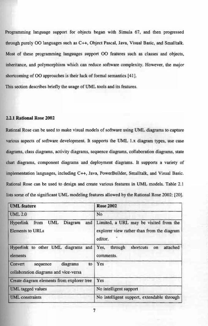
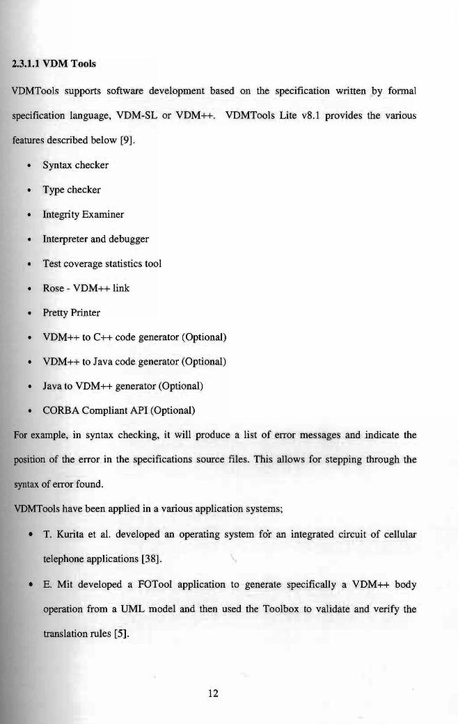