object-oriented decomposition of tire characteristics ... · pdf fileobject-oriented...
TRANSCRIPT

Object-Oriented Decomposition of Tire Characteristicsbased on semi-empirical Models
Markus AndresVorarlberg Univ. of Appl. Sc.
Dirk ZimmerETH ZürichSwitzerland
François E. CellierETH ZürichSwitzerland
Abstract
This article introduces a new and freely available Mod-elica library, called Wheels and Tires, for modelingwheels and tires. The contained models are intendedto be used in vehicle simulations, where computationalperformance is a major concern. Semi-empirical sin-gle contact point models are well suited for this kind ofapplications and are therefore applied in the presentedlibrary.
The Wheels and Tires library provides a tool toquickly build custom tire models, and allows a con-venient customization of existing models. This isachieved by a modular and expandable design systemutilizing well established models. In addition, a set ofready-made models is provided to allow a quick in-sight in the used modeling structure and to enable adirect application in vehicle models. The final versionof the library will be published as a free library viathe Modelica website as well as the website of F. E.Cellier.
Keywords: object-oriented tire modeling; object-oriented tyre modelling; semi-empirical tire model;tire decomposition
1 Introduction
During the last decades a fairly large number of tiremodels of varying levels of complexity suiting basi-cally differing fields of application have been devel-oped. These range from simple non-slipping tires tovery complex FEA (finite element analysis) models forperformance prediction [6].
The library developed is intended to be used in sim-ulations that cover entire vehicles, therefore compu-tational effort is an important issue. Hence, the selec-tion of the appropriate level of detail for the used mod-els is essential for the overall simulation performance.Semi-empirical single contact point models provide a
very good trade-off between accuracy and computa-tional effort. Such models are based on physical con-siderations, like those emerging from multibody dy-namics. These physical aspects get enhanced withempirical formulas representing measurement resultsthat cover e.g. friction and slip characteristics. Two ofthese semi-empirical models are commonly acceptedand widely used. These are TMeasy by G. Rill [11]and the magic-formula model by H. B. Pacejka [10].However, both are often implemented in a flat andmainly unstructured fashion, which makes them dif-ficult to understand and maintain. Customizing thesemodels for particular situations or expanding them inorder to cover new aspects of tires can be cumbersomeand is often error-prone.
A paper by D. Zimmer and M. Otter [14] buildson the previously mentioned models and demonstrateshow models of varying levels of complexity can be in-tegrated within the object-oriented framework of Mod-elica. However, the object orientation in these modelslimits itself primarily to their external interfaces. Themodels themselves continue to be mostly flat. For in-stance the most complex tire model created, definesapproximately 200 equations [14] and is a good exam-ple showing the difficulties that arise from the com-mon flat structure.
Another example for a quite flat structure can befound in the freely available but outdated Vehicle Dy-namics library [2]. There, a wheel-base model getsextended with friction models of [11] and [10], butnot much further effort was spent regarding object-orientation.
In [1], a tire model is modularized in hub, belt androad elements. A further enhancement is made in [5]by redesigning the model’s structure as well as en-abling uneven road surfaces and losing contact to theground due to enhanced vertical dynamics. This mod-ularization is well defined, but still the different as-pects of friction are summarized in the Tyre-Road class
Proceedings 7th Modelica Conference, Como, Italy, Sep. 20-22, 2009
© The Modelica Association, 2009 9 DOI: 10.3384/ecp09430029
and can not be customized easily. Moreover the li-braries presented in [14], [1] and [5] are not freelyavailable.
The newly developed library takes the object-orien-tation even further than in [5]. Therefore the focusof this research effort concerns itself less with mod-eling new tire properties, but more with an improvedorganization of existing knowledge. This will enablefuture modelers to conveniently customize the modelsto their own purposes.
2 Basic Considerations
2.1 A Closer Look at Tires
In motion dynamics of vehicles the forces exerted bythe tire-road contact are of major importance. Thissection is intended to provide basic knowledge abouttires buildup. For a more detailed information thereader is referred to [8], [9], [10] or [11].
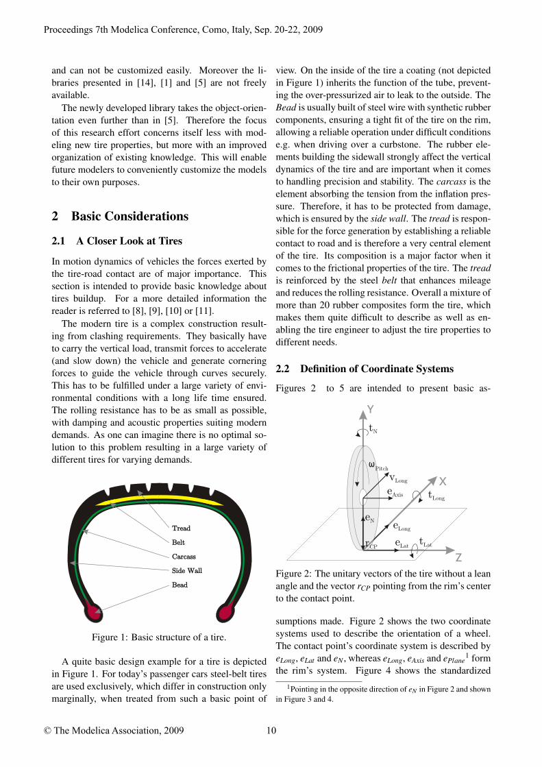
The modern tire is a complex construction result-ing from clashing requirements. They basically haveto carry the vertical load, transmit forces to accelerate(and slow down) the vehicle and generate corneringforces to guide the vehicle through curves securely.This has to be fulfilled under a large variety of envi-ronmental conditions with a long life time ensured.The rolling resistance has to be as small as possible,with damping and acoustic properties suiting moderndemands. As one can imagine there is no optimal so-lution to this problem resulting in a large variety ofdifferent tires for varying demands.
Tread
Belt
Carcass
Side Wall
Bead
Tread
Belt
Carcass
Side Wall
Bead
Figure 1: Basic structure of a tire.
A quite basic design example for a tire is depictedin Figure 1. For today’s passenger cars steel-belt tiresare used exclusively, which differ in construction onlymarginally, when treated from such a basic point of
view. On the inside of the tire a coating (not depictedin Figure 1) inherits the function of the tube, prevent-ing the over-pressurized air to leak to the outside. TheBead is usually built of steel wire with synthetic rubbercomponents, ensuring a tight fit of the tire on the rim,allowing a reliable operation under difficult conditionse.g. when driving over a curbstone. The rubber ele-ments building the sidewall strongly affect the verticaldynamics of the tire and are important when it comesto handling precision and stability. The carcass is theelement absorbing the tension from the inflation pres-sure. Therefore, it has to be protected from damage,which is ensured by the side wall. The tread is respon-sible for the force generation by establishing a reliablecontact to road and is therefore a very central elementof the tire. Its composition is a major factor when itcomes to the frictional properties of the tire. The treadis reinforced by the steel belt that enhances mileageand reduces the rolling resistance. Overall a mixture ofmore than 20 rubber composites form the tire, whichmakes them quite difficult to describe as well as en-abling the tire engineer to adjust the tire properties todifferent needs.
2.2 Definition of Coordinate Systems
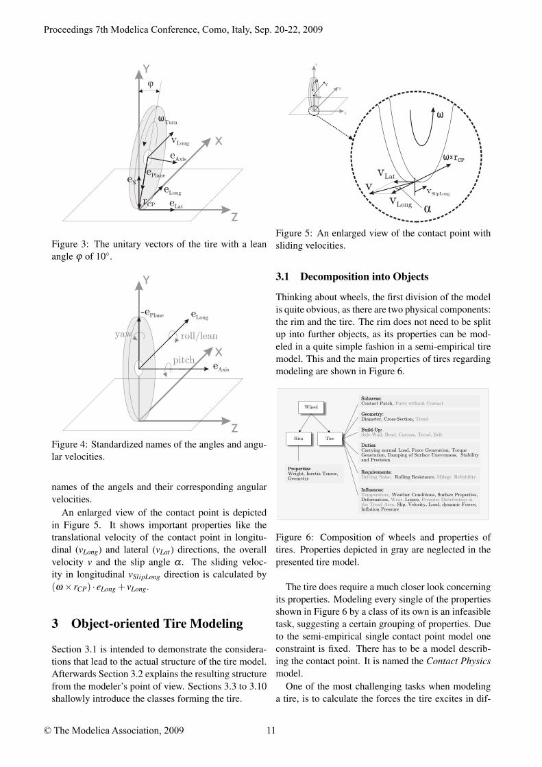
Figures 2 to 5 are intended to present basic as-
Y
X
Z
eAxis
eLat
eLong
rCP
eN
vLong
Pitch
tLong
tLat
tN
Figure 2: The unitary vectors of the tire without a leanangle and the vector rCP pointing from the rim’s centerto the contact point.
sumptions made. Figure 2 shows the two coordinatesystems used to describe the orientation of a wheel.The contact point’s coordinate system is described byeLong, eLat and eN , whereas eLong, eAxis and ePlane
1 formthe rim’s system. Figure 4 shows the standardized
1Pointing in the opposite direction of eN in Figure 2 and shownin Figure 3 and 4.
Proceedings 7th Modelica Conference, Como, Italy, Sep. 20-22, 2009
© The Modelica Association, 2009 10
Y
X
Z
eAxis
eLat
eLong
rCP
eN
vLong
ö
ePlane
Turn
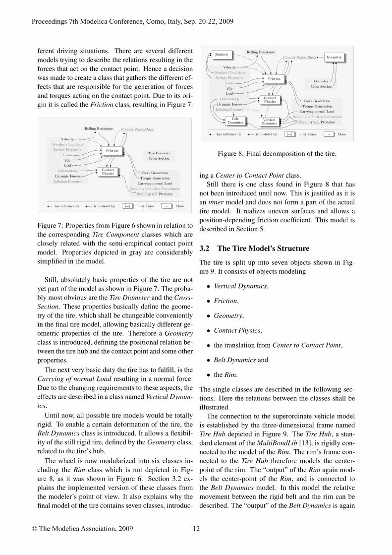
Figure 3: The unitary vectors of the tire with a leanangle ϕ of 10◦.
Y
X
Z
eAxis
eLong-ePlane
roll/lean
pitch
yaw
Figure 4: Standardized names of the angles and angu-lar velocities.
names of the angels and their corresponding angularvelocities.
An enlarged view of the contact point is depictedin Figure 5. It shows important properties like thetranslational velocity of the contact point in longitu-dinal (vLong) and lateral (vLat) directions, the overallvelocity v and the slip angle α . The sliding veloc-ity in longitudinal vSlipLong direction is calculated by(ω× rCP) · eLong + vLong.
3 Object-oriented Tire Modeling
Section 3.1 is intended to demonstrate the considera-tions that lead to the actual structure of the tire model.Afterwards Section 3.2 explains the resulting structurefrom the modeler’s point of view. Sections 3.3 to 3.10shallowly introduce the classes forming the tire.
Y
X
Z
v
rCP
vLong
x ù rCPx ù rCP
vSlipLong
vLat
v
á
Figure 5: An enlarged view of the contact point withsliding velocities.
3.1 Decomposition into Objects
Thinking about wheels, the first division of the modelis quite obvious, as there are two physical components:the rim and the tire. The rim does not need to be splitup into further objects, as its properties can be mod-eled in a quite simple fashion in a semi-empirical tiremodel. This and the main properties of tires regardingmodeling are shown in Figure 6.
Wheel
Rim Tire
Subareas: Contact Patch, Parts without ContactSubareas:
Geometry:Diameter, Cross-Section, TreadGeometry:
Build-Up:Side-Wall, Bead, Carcass, Tread, BeltBuild-Up:
Duties:Carrying normal Load, Force Generation, Torque Generation, Damping of Surface Unevenness, Stability and Precision
Duties:
Requirements: Rolling Resistance, Driving Noise, Milage, Reliability
Requirements:
Influences:Weather Conditions, Surface Properties,
Deformation, Losses, Slip, Velocity, Load, dynamic Forces,
Inflation Pressure
Temperature, Wear, Pressure Distribution in
the Tread Area,
Influences:
Properties:Weight, Inertia Tensor, Geometry
Properties:
Figure 6: Composition of wheels and properties oftires. Properties depicted in gray are neglected in thepresented tire model.
The tire does require a much closer look concerningits properties. Modeling every single of the propertiesshown in Figure 6 by a class of its own is an infeasibletask, suggesting a certain grouping of properties. Dueto the semi-empirical single contact point model oneconstraint is fixed. There has to be a model describ-ing the contact point. It is named the Contact Physicsmodel.
One of the most challenging tasks when modelinga tire, is to calculate the forces the tire excites in dif-
Proceedings 7th Modelica Conference, Como, Italy, Sep. 20-22, 2009
© The Modelica Association, 2009 11
ferent driving situations. There are several differentmodels trying to describe the relations resulting in theforces that act on the contact point. Hence a decisionwas made to create a class that gathers the different ef-fects that are responsible for the generation of forcesand torques acting on the contact point. Due to its ori-gin it is called the Friction class, resulting in Figure 7.
FrictionTire Diameter
Cross-Section
Force Generation
Torque Generation
Carrying normal Load
Stability and Precision
Damping of Surface Unevenness
Rolling Resistance
Velocity
Slip
Load
Dynamic Forces
Weather Conditions
Surface Properties
Losses
Deformation
Inflation Pressure
Contact Physics
has influence on is modeled by Classinner Class[...] ...
Contact Patch/Point
Figure 7: Properties from Figure 6 shown in relation tothe corresponding Tire Component classes which areclosely related with the semi-empirical contact pointmodel. Properties depicted in gray are considerablysimplified in the model.
Still, absolutely basic properties of the tire are notyet part of the model as shown in Figure 7. The proba-bly most obvious are the Tire Diameter and the Cross-Section. These properties basically define the geome-try of the tire, which shall be changeable convenientlyin the final tire model, allowing basically different ge-ometric properties of the tire. Therefore a Geometryclass is introduced, defining the positional relation be-tween the tire hub and the contact point and some otherproperties.
The next very basic duty the tire has to fulfill, is theCarrying of normal Load resulting in a normal force.Due to the changing requirements to these aspects, theeffects are described in a class named Vertical Dynam-ics.
Until now, all possible tire models would be totallyrigid. To enable a certain deformation of the tire, theBelt Dynamics class is introduced. It allows a flexibil-ity of the still rigid tire, defined by the Geometry class,related to the tire’s hub.
The wheel is now modularized into six classes in-cluding the Rim class which is not depicted in Fig-ure 8, as it was shown in Figure 6. Section 3.2 ex-plains the implemented version of these classes fromthe modeler’s point of view. It also explains why thefinal model of the tire contains seven classes, introduc-
Friction
Contact Patch/Point
Diameter
Cross-Section
Force Generation
Torque Generation
Carrying normal Load
Stability and Precision
Damping of Surface Unevenness
Rolling Resistance
Velocity
Slip
Load
Dynamic Forces
Weather Conditions
Surface Properties
Losses
Deformation
Inflation Pressure
Contact Physics
Vertical Dynamics
Geometry
Belt Dynamics
[Surface]
has influence on is modeled by Classinner Class[...] ...
Figure 8: Final decomposition of the tire.
ing a Center to Contact Point class.Still there is one class found in Figure 8 that has
not been introduced until now. This is justified as it isan inner model and does not form a part of the actualtire model. It realizes uneven surfaces and allows aposition-depending friction coefficient. This model isdescribed in Section 5.
3.2 The Tire Model’s Structure
The tire is split up into seven objects shown in Fig-ure 9. It consists of objects modeling
• Vertical Dynamics,
• Friction,
• Geometry,
• Contact Physics,
• the translation from Center to Contact Point,
• Belt Dynamics and
• the Rim.
The single classes are described in the following sec-tions. Here the relations between the classes shall beillustrated.
The connection to the superordinate vehicle modelis established by the three-dimensional frame namedTire Hub depicted in Figure 9. The Tire Hub, a stan-dard element of the MultiBondLib [13], is rigidly con-nected to the model of the Rim. The rim’s frame con-nected to the Tire Hub therefore models the center-point of the rim. The “output” of the Rim again mod-els the center-point of the Rim, and is connected tothe Belt Dynamics model. In this model the relativemovement between the rigid belt and the rim can bedescribed. The “output” of the Belt Dynamics is again
Proceedings 7th Modelica Conference, Como, Italy, Sep. 20-22, 2009
© The Modelica Association, 2009 12
v
ContactPhysics
F,T
FrictioneN
eLong
eLat
tN
tLong
tLat fLong
fLat
ideal
RimBeltDynamics
Geometry
Ideal slim
center2CPcenter2CP
VerticalDynamics
no
fr... fr... fr...
TireHub
fr...fr...
Figure 9: Model of the ideal tire showing the sevenused objects and the communication structure on thetop level. The Tire Bus is colored red whereas the Con-tact Point Connector is green.
positioned at the center-point of the belt. Therefore anelement is needed to realize the translation from thispoint to the contact point. As this cannot be mod-eled by a standard element, the Center To ContactPoint model has been created. It connects the ContactPhysics model that applies forces and torques to thecontact point. This lower part of the model representsthe mechanically connected part of the model. The up-per three classes are not directly connected by a me-chanical connector, although the Contact Point Con-nector implies kind of a mechanical connection. TheVertical Dynamics class determines if and how the tireis able to lift from the ground and how it responds tonormal load. The Friction class determines the longi-tudinal and lateral forces as well as the torques that acton the contact point. Finally, the Geometry class de-termines the unitary vectors shown in Figure 2 and theposition of the contact point depending on the actualgeometry, position and orientation of the tire.
The visualization is implemented in the correspond-ing object, e.g. the rim is visualized in the Rim ob-ject and the tire is visualized in the Geometry class.This makes it possible to recognize basic changes tothe models in the animation directly.
All of the featured classes that model a certain typeof effect are extended from the corresponding baseclass, ensuring that the necessary output is calculated.This guarantees also that all models stay exchangeablenot depending on the implementation of the class. Inthis way, the user can add new classes or adapt existingones being sure that the other elements stay unchangedand remain exchangeable.
3.3 Rim Class
The Rim Class is a rather simple model, as the rim canbe modeled ideally just consisting of a body that has amass and an inertia tensor.
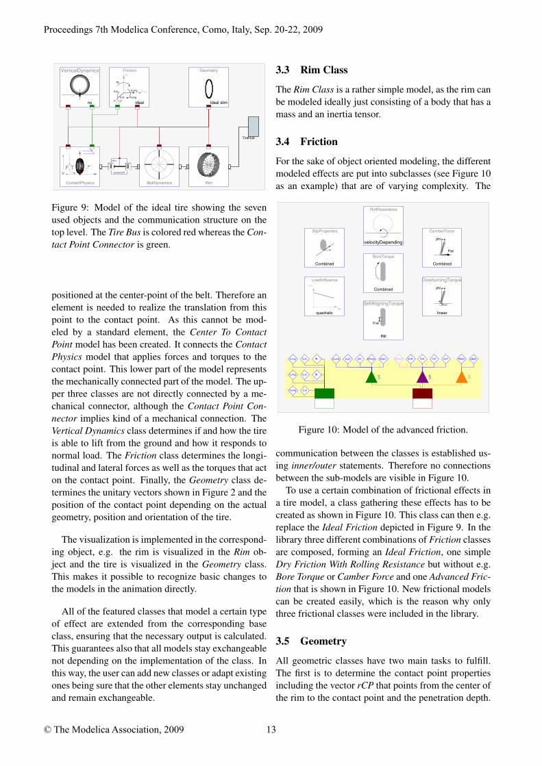
3.4 Friction
For the sake of object oriented modeling, the differentmodeled effects are put into subclasses (see Figure 10as an example) that are of varying complexity. The
SlipProperties
Combined
BoreTorque
Combined
CamberForce
phi
Flat
Combined
SelfAligningTorque
lTrail
Rill
RollResistance
velocityDepending
LoadInfluencemu
fN
quadratic
OverturningTorque
tOver
phi
linear
UV
CP
SV
RBelt wBeltrCPlCRbCReLong ContacteAxisePlaneeNeLatfLong fLat fN
vLong vLat
tLong tLat tN
xCP
Figure 10: Model of the advanced friction.
communication between the classes is established us-ing inner/outer statements. Therefore no connectionsbetween the sub-models are visible in Figure 10.
To use a certain combination of frictional effects ina tire model, a class gathering these effects has to becreated as shown in Figure 10. This class can then e.g.replace the Ideal Friction depicted in Figure 9. In thelibrary three different combinations of Friction classesare composed, forming an Ideal Friction, one simpleDry Friction With Rolling Resistance but without e.g.Bore Torque or Camber Force and one Advanced Fric-tion that is shown in Figure 10. New frictional modelscan be created easily, which is the reason why onlythree frictional classes were included in the library.
3.5 Geometry
All geometric classes have two main tasks to fulfill.The first is to determine the contact point propertiesincluding the vector rCP that points from the center ofthe rim to the contact point and the penetration depth.
Proceedings 7th Modelica Conference, Como, Italy, Sep. 20-22, 2009
© The Modelica Association, 2009 13
Secondly the unit vectors shown in Figure 2 get com-puted by the Geometry class. To enable that func-tionality it utilizes the Surface’s functions get_eN andget_elevation establishing the connection from the tireto the surface.
Three different Geometry classes are provided forideally Slim, Circular tires with cross-section beingmodeled as a semi-circle, and a “Belt” profile with sidewalls and a sector of a circle modeling the tread area.
3.6 Contact Physics
The Contact Physics model applies forces and torqueson the contact point, as well as measuring its veloc-ities. All these physical quantities are connected tothe models determining frictional and vertical dynamicproperties via the Contact Point Connector. Measur-ing and setting of speeds and forces has to be done inan a-casual way as ideal models set velocities ratherthen apply forces.
The second property determined by the ContactPhysics class is the dynamic behavior of the contactpoint. It can introduce flexibility of the contact pointin longitudinal and lateral direction.
3.7 Center to Contact Point
The Center To Contact Point class is a model with-out a nice physical interpretation. It is kind of a FixedTranslation element known from the Modelica Stan-dard Library. The model is built using multi-bondgraphs and therefore derived from the Fixed Transla-tion in the MultiBondLib [13]. It describes the con-nection between the contact point and the belt’s centerpoint.
3.8 Vertical Dynamics
The models in the Vertical Dynamics package deter-mine the behavior of the tire normal to the surface. Thenormal force is related to the penetration depth com-puted in the Geometry class. The Vertical Dynamicsmodels can either set the penetration depth to a cer-tain value, or use it as a base for the calculation of thenormal force fN .
There are basically three different approaches tomodel vertical dynamics in the library. One is to not al-low any elevation from the ground or penetration intoit introducing a holonomic constraint. The second uti-lizes an ElevationGap model that compensates forcesof a attached 1D mechanical model when the tire liftsfrom the ground. It is a derivation from the ElastoGap
model found in the BondLib [7]. It makes the verticaldynamics easily changeable by a modification of the1D mechanical system. The third is a derivation of theElastoGap model of the Modelica Standard Library3.0. It overcomes the sticking effect of the Elevation-Gap but is harder to adapt to different dynamics.
3.9 Belt Dynamics
The models described in this section allow the tire tohave a certain flexibility. This is realized by connect-ing an ideal (virtual) belt to the ideal rim in a flexi-ble fashion. All models except the Rigid Belt modeladd a considerable amount of complexity to the sim-ulation. Different models are provided to realize thedynamic behavior. One allows translation of the beltin longitudinal and lateral direction, another modelsa rotational degree of freedom around the axis of ro-tation, both defining the dynamics by 1D mechanicalelements. The last model is the most complex with thedynamics defined by four ideally stiff translational el-ements for rim and belt respectively, connected by 3Dspring damper systems.
3.10 Communication Structure
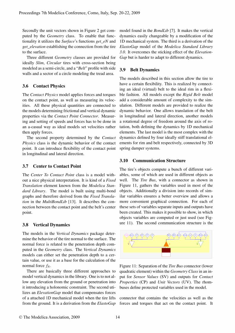
The tire’s objects compute a bunch of different vari-ables, some of which are used in different objects aswell. The Tire Bus, with a connector as shown inFigure 11, gathers the variables used in most of theobjects. Additionally a division into records of sim-ilar variables ensures a better overview and allows amore convenient graphical connection. For each ofthese sets of variables separate inputs and outputs havebeen created. This makes it possible to show, in whichobjects variables are computed or just used (see Fig-ure 11). The second communication structure is the
CP
SV
UV
RBelt eLong eAxisePlaneeNeAxisS...Contact penetra... xBeltlCR bCR rCP eLatxCP
Figure 11: Separation of the Tire Bus connector (lowerquadratic element) within the Geometry Class in an in-put for Sensor Values (SV) and outputs for ContactProperties (CP) and Unit Vectors (UV). The rhom-buses define protected variables used in the model.
connector that contains the velocities as well as theforces and torques that act on the contact point. It
Proceedings 7th Modelica Conference, Como, Italy, Sep. 20-22, 2009
© The Modelica Association, 2009 14
is named Contact Point Connector. This connectoris implemented in an a-causal manner due to the re-quirements of this connection. It can be found con-necting Contact Physics, Vertical Dynamics and Fric-tion. Both bus connectors are illustrated in Figure 9.
4 Provided Tire Models
All tires are basically built up like the ideal tire in Fig-ure 9. In the library eleven ready-made tires are pro-vided for a quick application and a better understand-ing of the model structure. Four models of slim tiresinclude three rigid versions and one with a dynami-cally behaving contact point. Two tires with semi-circular cross section are provided, one rigid and theother having rotational dynamics. The so-called beltedtires feature three rigid models differing in frictionalbehavior. The other two belted tires behave dynami-cally.
5 Environment
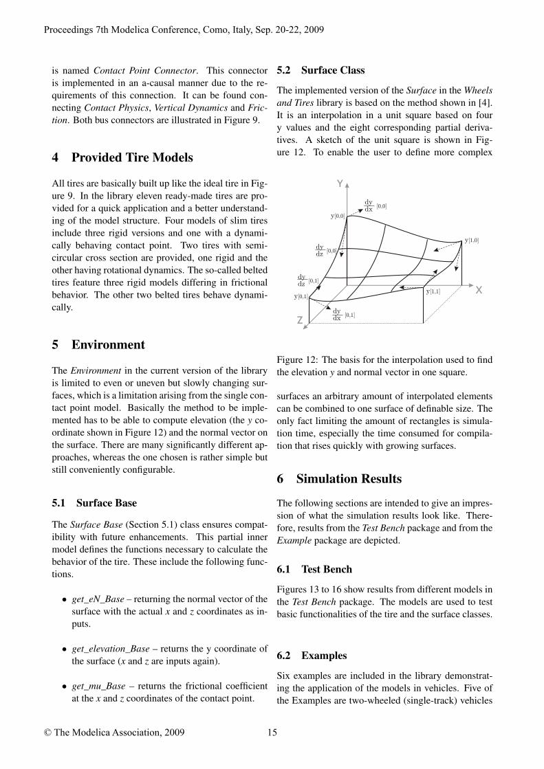
The Environment in the current version of the libraryis limited to even or uneven but slowly changing sur-faces, which is a limitation arising from the single con-tact point model. Basically the method to be imple-mented has to be able to compute elevation (the y co-ordinate shown in Figure 12) and the normal vector onthe surface. There are many significantly different ap-proaches, whereas the one chosen is rather simple butstill conveniently configurable.
5.1 Surface Base
The Surface Base (Section 5.1) class ensures compat-ibility with future enhancements. This partial innermodel defines the functions necessary to calculate thebehavior of the tire. These include the following func-tions.
• get_eN_Base – returning the normal vector of thesurface with the actual x and z coordinates as in-puts.
• get_elevation_Base – returns the y coordinate ofthe surface (x and z are inputs again).
• get_mu_Base – returns the frictional coefficientat the x and z coordinates of the contact point.
5.2 Surface Class
The implemented version of the Surface in the Wheelsand Tires library is based on the method shown in [4].It is an interpolation in a unit square based on foury values and the eight corresponding partial deriva-tives. A sketch of the unit square is shown in Fig-ure 12. To enable the user to define more complex
Y
X
dy
y[0,0]
Z
y[1,0]
y[0,1]y[1,1]
dx [0,0]
dydz [0,0]
dydx [0,1]
dydz [0,1]
Figure 12: The basis for the interpolation used to findthe elevation y and normal vector in one square.
surfaces an arbitrary amount of interpolated elementscan be combined to one surface of definable size. Theonly fact limiting the amount of rectangles is simula-tion time, especially the time consumed for compila-tion that rises quickly with growing surfaces.
6 Simulation Results
The following sections are intended to give an impres-sion of what the simulation results look like. There-fore, results from the Test Bench package and from theExample package are depicted.
6.1 Test Bench
Figures 13 to 16 show results from different models inthe Test Bench package. The models are used to testbasic functionalities of the tire and the surface classes.
6.2 Examples
Six examples are included in the library demonstrat-ing the application of the models in vehicles. Five ofthe Examples are two-wheeled (single-track) vehicles
Proceedings 7th Modelica Conference, Como, Italy, Sep. 20-22, 2009
© The Modelica Association, 2009 15
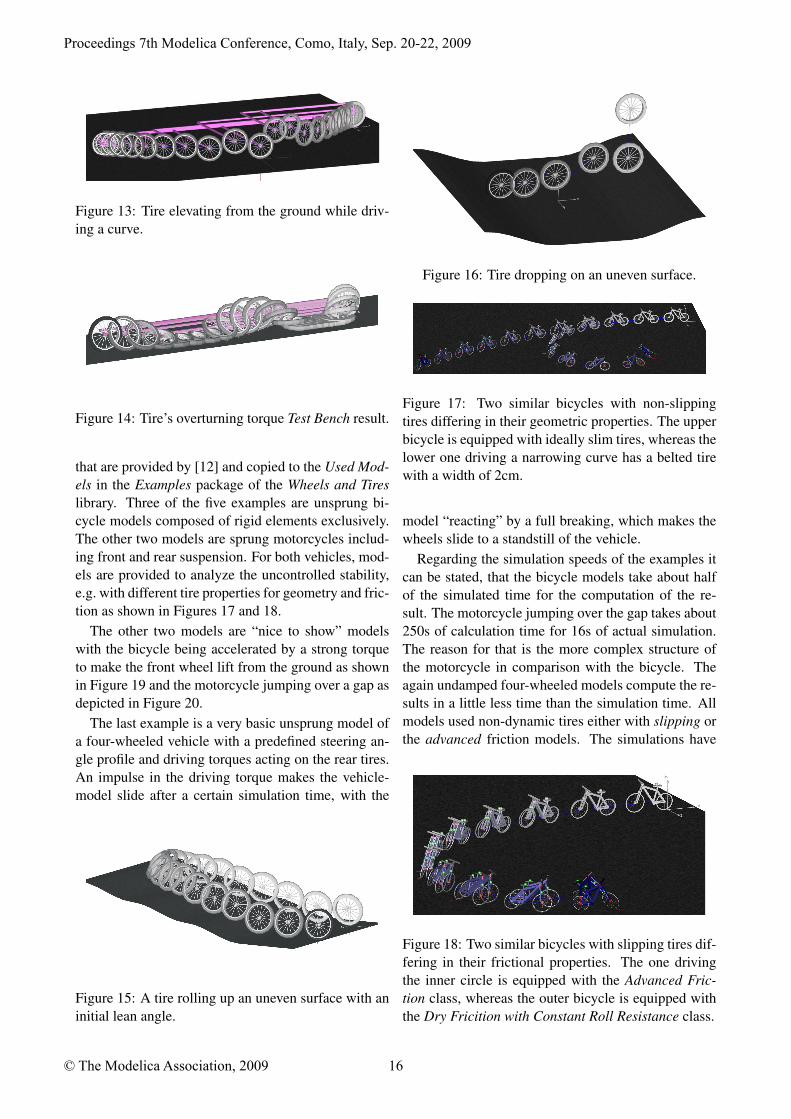
Figure 13: Tire elevating from the ground while driv-ing a curve.
Figure 14: Tire’s overturning torque Test Bench result.
that are provided by [12] and copied to the Used Mod-els in the Examples package of the Wheels and Tireslibrary. Three of the five examples are unsprung bi-cycle models composed of rigid elements exclusively.The other two models are sprung motorcycles includ-ing front and rear suspension. For both vehicles, mod-els are provided to analyze the uncontrolled stability,e.g. with different tire properties for geometry and fric-tion as shown in Figures 17 and 18.
The other two models are “nice to show” modelswith the bicycle being accelerated by a strong torqueto make the front wheel lift from the ground as shownin Figure 19 and the motorcycle jumping over a gap asdepicted in Figure 20.
The last example is a very basic unsprung model ofa four-wheeled vehicle with a predefined steering an-gle profile and driving torques acting on the rear tires.An impulse in the driving torque makes the vehicle-model slide after a certain simulation time, with the
Figure 15: A tire rolling up an uneven surface with aninitial lean angle.
Figure 16: Tire dropping on an uneven surface.
Figure 17: Two similar bicycles with non-slippingtires differing in their geometric properties. The upperbicycle is equipped with ideally slim tires, whereas thelower one driving a narrowing curve has a belted tirewith a width of 2cm.
model “reacting” by a full breaking, which makes thewheels slide to a standstill of the vehicle.
Regarding the simulation speeds of the examples itcan be stated, that the bicycle models take about halfof the simulated time for the computation of the re-sult. The motorcycle jumping over the gap takes about250s of calculation time for 16s of actual simulation.The reason for that is the more complex structure ofthe motorcycle in comparison with the bicycle. Theagain undamped four-wheeled models compute the re-sults in a little less time than the simulation time. Allmodels used non-dynamic tires either with slipping orthe advanced friction models. The simulations have
Figure 18: Two similar bicycles with slipping tires dif-fering in their frictional properties. The one drivingthe inner circle is equipped with the Advanced Fric-tion class, whereas the outer bicycle is equipped withthe Dry Fricition with Constant Roll Resistance class.
Proceedings 7th Modelica Conference, Como, Italy, Sep. 20-22, 2009
© The Modelica Association, 2009 16
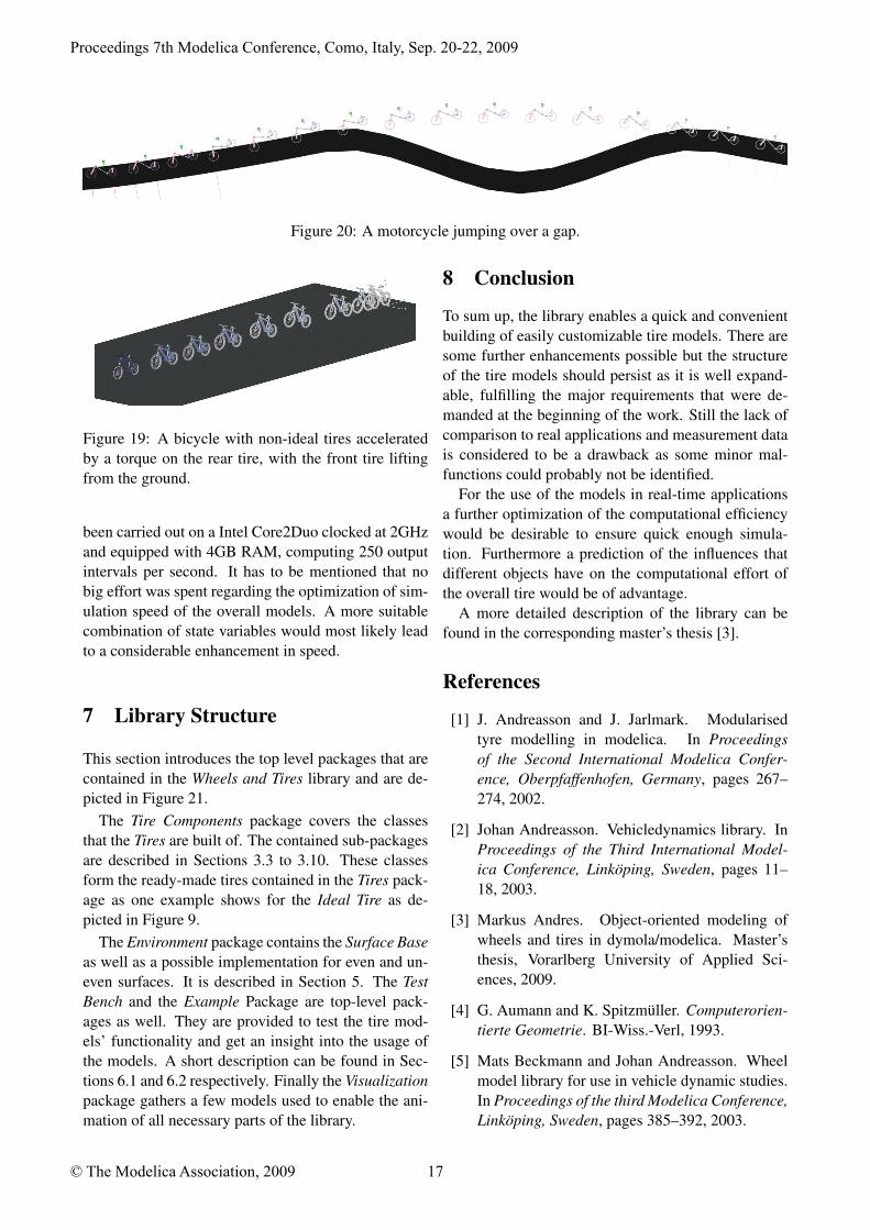
Figure 20: A motorcycle jumping over a gap.
Figure 19: A bicycle with non-ideal tires acceleratedby a torque on the rear tire, with the front tire liftingfrom the ground.
been carried out on a Intel Core2Duo clocked at 2GHzand equipped with 4GB RAM, computing 250 outputintervals per second. It has to be mentioned that nobig effort was spent regarding the optimization of sim-ulation speed of the overall models. A more suitablecombination of state variables would most likely leadto a considerable enhancement in speed.
7 Library Structure
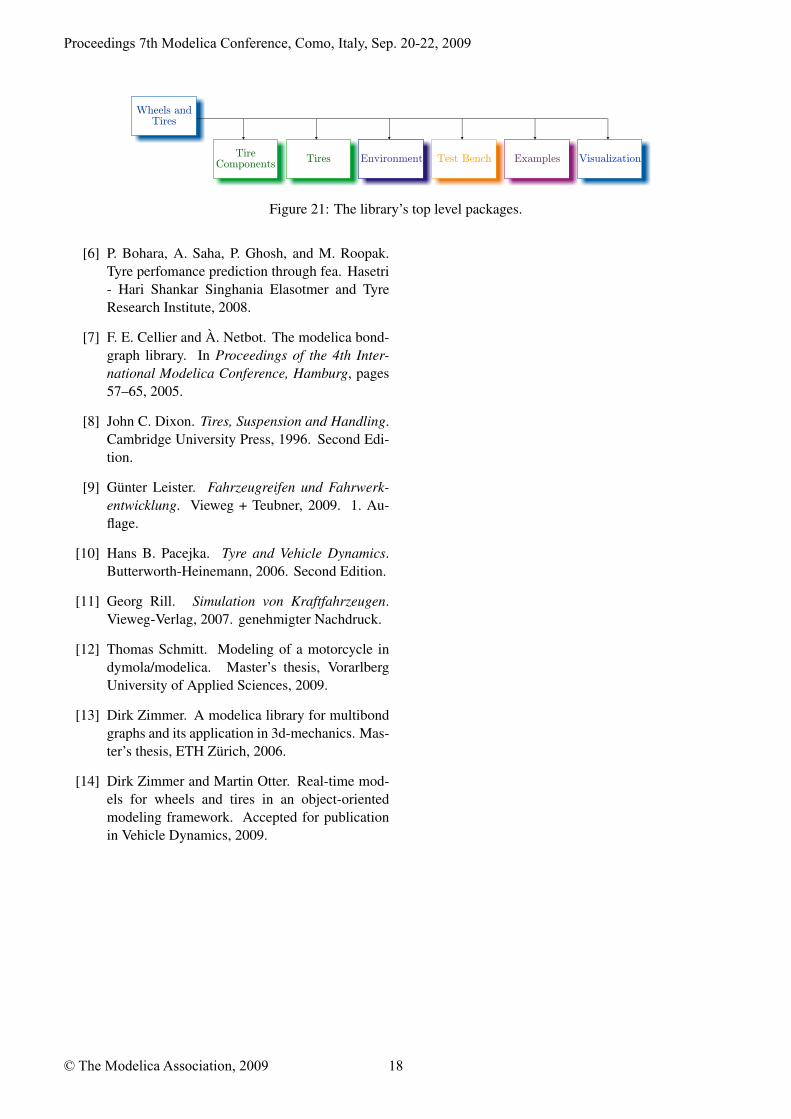
This section introduces the top level packages that arecontained in the Wheels and Tires library and are de-picted in Figure 21.
The Tire Components package covers the classesthat the Tires are built of. The contained sub-packagesare described in Sections 3.3 to 3.10. These classesform the ready-made tires contained in the Tires pack-age as one example shows for the Ideal Tire as de-picted in Figure 9.
The Environment package contains the Surface Baseas well as a possible implementation for even and un-even surfaces. It is described in Section 5. The TestBench and the Example Package are top-level pack-ages as well. They are provided to test the tire mod-els’ functionality and get an insight into the usage ofthe models. A short description can be found in Sec-tions 6.1 and 6.2 respectively. Finally the Visualizationpackage gathers a few models used to enable the ani-mation of all necessary parts of the library.
8 Conclusion
To sum up, the library enables a quick and convenientbuilding of easily customizable tire models. There aresome further enhancements possible but the structureof the tire models should persist as it is well expand-able, fulfilling the major requirements that were de-manded at the beginning of the work. Still the lack ofcomparison to real applications and measurement datais considered to be a drawback as some minor mal-functions could probably not be identified.
For the use of the models in real-time applicationsa further optimization of the computational efficiencywould be desirable to ensure quick enough simula-tion. Furthermore a prediction of the influences thatdifferent objects have on the computational effort ofthe overall tire would be of advantage.
A more detailed description of the library can befound in the corresponding master’s thesis [3].
References
[1] J. Andreasson and J. Jarlmark. Modularisedtyre modelling in modelica. In Proceedingsof the Second International Modelica Confer-ence, Oberpfaffenhofen, Germany, pages 267–274, 2002.
[2] Johan Andreasson. Vehicledynamics library. InProceedings of the Third International Model-ica Conference, Linköping, Sweden, pages 11–18, 2003.
[3] Markus Andres. Object-oriented modeling ofwheels and tires in dymola/modelica. Master’sthesis, Vorarlberg University of Applied Sci-ences, 2009.
[4] G. Aumann and K. Spitzmüller. Computerorien-tierte Geometrie. BI-Wiss.-Verl, 1993.
[5] Mats Beckmann and Johan Andreasson. Wheelmodel library for use in vehicle dynamic studies.In Proceedings of the third Modelica Conference,Linköping, Sweden, pages 385–392, 2003.
Proceedings 7th Modelica Conference, Como, Italy, Sep. 20-22, 2009
© The Modelica Association, 2009 17
Wheels and Tires
Tire Components Tires Environment Test Bench Examples Visualization
Figure 21: The library’s top level packages.
[6] P. Bohara, A. Saha, P. Ghosh, and M. Roopak.Tyre perfomance prediction through fea. Hasetri- Hari Shankar Singhania Elasotmer and TyreResearch Institute, 2008.
[7] F. E. Cellier and À. Netbot. The modelica bond-graph library. In Proceedings of the 4th Inter-national Modelica Conference, Hamburg, pages57–65, 2005.
[8] John C. Dixon. Tires, Suspension and Handling.Cambridge University Press, 1996. Second Edi-tion.
[9] Günter Leister. Fahrzeugreifen und Fahrwerk-entwicklung. Vieweg + Teubner, 2009. 1. Au-flage.
[10] Hans B. Pacejka. Tyre and Vehicle Dynamics.Butterworth-Heinemann, 2006. Second Edition.
[11] Georg Rill. Simulation von Kraftfahrzeugen.Vieweg-Verlag, 2007. genehmigter Nachdruck.
[12] Thomas Schmitt. Modeling of a motorcycle indymola/modelica. Master’s thesis, VorarlbergUniversity of Applied Sciences, 2009.
[13] Dirk Zimmer. A modelica library for multibondgraphs and its application in 3d-mechanics. Mas-ter’s thesis, ETH Zürich, 2006.
[14] Dirk Zimmer and Martin Otter. Real-time mod-els for wheels and tires in an object-orientedmodeling framework. Accepted for publicationin Vehicle Dynamics, 2009.
Proceedings 7th Modelica Conference, Como, Italy, Sep. 20-22, 2009
© The Modelica Association, 2009 18