vaisala indigo 201 analog output transmitter quick … 201 quick guide introduction to indigo™...
TRANSCRIPT

M211876EN-B
Quick GuideIndigo™ 201 Analog Output Transmitter
Indigo 201

PUBLISHED BY
Vaisala Oyj Street address: Vanha Nurmijärventie 21, FI-01670 Vantaa, FinlandMailing address: P.O. Box 26, FI-00421 Helsinki, FinlandPhone: +358 9 8949 1Fax: +358 9 8949 2227
Visit our Internet pages at www.vaisala.com.
© Vaisala Oyj 2017
No part of this manual may be reproduced,published or publicly displayed in any formor by any means, electronic or mechanical(including photocopying), nor may itscontents be modified, translated, adapted,sold or disclosed to a third party withoutprior written permission of the copyrightholder. Translated manuals and translatedportions of multilingual documents arebased on the original English versions. Inambiguous cases, the English versions areapplicable, not the translations.
The contents of this manual are subject tochange without prior notice.
Local rules and regulations may vary andthey shall take precedence over theinformation contained in this manual.Vaisala makes no representations on thismanual’s compliance with the local rulesand regulations applicable at any giventime, and hereby disclaims any and allresponsibilities related thereto.
This manual does not create any legallybinding obligations for Vaisala towardscustomers or end users. All legally bindingobligations and agreements are included
exclusively in the applicable supplycontract or the General Conditions of Saleand General Conditions of Service ofVaisala.
This product contains software developedby Vaisala or third parties. Use of thesoftware is governed by license terms andconditions included in the applicablesupply contract or, in the absence ofseparate license terms and conditions, bythe General License Conditions of VaisalaGroup.
This product may contain open sourcesoftware (OSS) components. In the eventthis product contains OSS components,then such OSS is governed by the termsand conditions of the applicable OSSlicenses, and you are bound by the termsand conditions of such licenses inconnection with your use and distributionof the OSS in this product. Applicable OSSlicenses are included in the product itselfor provided to you on any other applicablemedia, depending on each individualproduct and the product items deliveredto you.

Table of Contents
Indigo 201 Quick Guide..................................................................................... 3
Introduction to Indigo™ Transmitters.................................................................. 3Indigo 201 Basic Features and Options.........................................................3
Input and Output Specification............................................................................4Indigo Transmitter Parts........................................................................................5Wiring Options....................................................................................................... 6Mounting................................................................................................................. 7Indigo 201 Transmitter Base................................................................................. 8Attaching Probes and Cables............................................................................... 9Connecting to Wireless Configuration Interface.............................................. 10Logging in to Wireless Configuration Interface................................................. 11Wireless Interface Menus..................................................................................... 12
Table of Contents
1

Indigo 201 Quick Guide M211876EN-B
2

Indigo 201 Quick Guide
Introduction to Indigo™ Transmitters
1.35% | Carbon dioxide
WLAN is activated
Indigo 201
Figure 1 Indigo 201 With and Without Display, Wireless Interface Examples
Vaisala Indigo transmitters are a plug-and-play host device platform for Vaisala Indigo-compatible probes. Indigo transmitters extend the feature set of connected probes with a range of additional options for outputs, measurement viewing, status monitoring, and configuration interface access.
Depending on the Indigo model, a display is available as an optional selection or as a standard feature. In the non-display model, an LED indicator is used for notifications. The configuration interface of Indigo transmitters is a browser-based wireless UI that requires a mobile device or computer that supports wireless connectivity (IEEE 802.11 b/g/n WLAN).
Indigo 201 Basic Features and Options• All Vaisala Indigo-compatible probes can be connected to all Indigo transmitter models• Plug-and-play probe installation: when unconfigured, Indigo automatically adapts the
analog output configuration of the connected Indigo-compatible probe• Wireless configuration interface: connect to the scalable browser-based UI of Indigo
201 to change probe and transmitter settings, view measurements and review probeand transmitter status
• 3.5” TFT LCD color display or non-display model with LED indicator• Power supply input 15 ... 30 VDC (20 ... 22 VAC)• 3 current (mA) or voltage (V) analog outputs• 2 configurable relays
Chapter 1 – Indigo 201 Quick Guide
3

Input and Output Specif ication
Table 1 Input and Output
Property Specification
Analog outputs 3 voltage (V) or current (mA) outputs:
• 0 … 10 V / 0 … 5 V / 0 … 1 V / 1 … 5 V (min. load1kΩ)
• 0 … 20 mA / 4 … 20 mA (max. load 500 Ω)
Relays 2 configurable relays (VAC/VDC)
Device maximum specification (resistive load):
• Max. switching power 30 W / 37.5 VA
UL-rated maximum specification (resistive load):
• AC: max. 28 V / 0.5 A• DC: max. 40 V / 0.24 A• Up to 30 VDC:
• max. switching current 1 A• max. switching power 30 W
Power supply input 1) Range 15 ... 30 VDC (20 ... 22 VAC)
Maximum current Transmitter and connected probe max. 1 A
Power consumption Transmitter max. 3 W (+ connected probe, variesdepending on probe type)
Probe connector M12/5 connector for probe or probe cable connection(Vaisala Indigo-compatible probes)
Cable feed throughs 2 options: rubber lead-through on the bottom of thetransmitter, and opening with a seal at the back of thetransmitter
Screw terminal wire size 0.2 mm2 ... 1.5 mm2
1) Using a power supply with overload protection is recommended for electrical safety.
Do not modify the unit or use it in ways not described in the documentation.Improper modification may lead to safety hazards, equipment damage, failure toperform according to specification, or decreased equipment lifetime.
CAUTION!
Indigo 201 Quick Guide M211876EN-B
4

Indigo Transmitter Parts
2
3
4
5
7
6
1
Figure 2 Indigo Transmitter Parts
1 Display (optional)2 LED indicator (in non-display model)3 Probe and probe cable connector, locking wheel4 Wireless (WLAN) configuration interface activation button5 Rubber lead-through with strain relief for input/output cable6 Top cover of the transmitter: LED/display, circuit board and connector pins7 Transmitter base: input and output wiring (screw terminals), mounting base
Only use Vaisala Indigo-compatible probes with the transmitter. Attemptingto connect incompatible probes or probe cables can damage the equipment.CAUTION!
Chapter 1 – Indigo 201 Quick Guide
5
1
2
7-8 mmØ
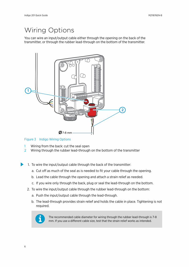
Figure 3 Indigo Wiring Options
1 Wiring from the back: cut the seal open2 Wiring through the rubber lead-through on the bottom of the transmitter
1. To wire the input/output cable through the back of the transmitter:
a. Cut off as much of the seal as is needed to fit your cable through the opening.
b. Lead the cable through the opening and attach a strain relief as needed.
c. If you wire only through the back, plug or seal the lead-through on the bottom.
2. To wire the input/output cable through the rubber lead-through on the bottom:
a. Push the input/output cable through the lead-through.
b. The lead-through provides strain relief and holds the cable in place. Tightening is notrequired.
The recommended cable diameter for wiring through the rubber lead-through is 7-8mm. If you use a different cable size, test that the strain relief works as intended.
Indigo 201 Quick Guide
Wiring OptionsYou can wire an input/output cable either through the opening on the back of the transmitter, or through the rubber lead-through on the bottom of the transmitter.
M211876EN-B
6

Mounting1. Open the 4 screws on the transmitter cover and pull the cover off the base.
To avoid damaging the connector pins of the transmitter, pull thetransmitter cover off the base in a straight angle. Do not twist or bend.CAUTION!
2. Place the transmitter base on the installation surface and mount it with 3 screws. Seethe screw positions in Figure 4 (page 8).
3. Lead the input/output cable inside the transmitter (see Wiring Options (page 6)). If you are wiring through the lead-through on the bottom of the transmitter, test that the strain relief works with your cable.
4. Connect the input/output cable's wiring to the screw terminals (see Indigo 201 Transmitter Base (page 8)) and reattach the cover when done.
5. When you have f inished wiring and reattached the cover, switch on the power supply input.
Chapter 1 – Indigo 201 Quick Guide
7

Indigo 201 Transmitter Base
1 2 4
5
6
3
INDIGO 201 ANALOG
OUTPUT TRANSMITTER
Serial No. SX12345678
Figure 4 Indigo 201 Transmitter Base Main Parts and Screw Positions
1 Probe and probe cable connector inside the locking wheel2 Wireless (WLAN) configuration interface activation button3 Wiring from the back: cut open the seal4 Rubber cable lead-through with strain relief5 Screw terminals for analog outputs 1-3 and relays A and B6 Screw terminals for power supply input
Do not energize the power supply before the wiring has been connected.CAUTION!
Indigo 201 Quick Guide M211876EN-B
8

Attaching Probes and Cables
1
2
3
Figure 5 Attaching Probes and Cables to Indigo
1 Insert probes into the probe connector with the orientation mark facing out.2 Probes are locked in place with the locking wheel. Never turn from the probe body.3 Connect probe cables in the same way as probes: insert the cable in the connector and
hold in place while turning the locking wheel.
1. Insert the probe into the probe connector with the orientation mark on the probe bodyfacing out.
2. Hold the probe in the probe connector and lock it in place by turning the locking wheelcounterclockwise. Do not turn the probe body when attaching, only the locking wheelon the transmitter.
3. If no previous configuration exists (that is, this is the first time a probe is connected toIndigo, and no configuration has been set manually), Indigo adapts the analog outputconfiguration of the connected Vaisala Indigo-compatible probe automatically.
If a configuration that differs from the attached probe's configuration exists in thetransmitter, you must configure the new probe manually to enable analog output.For more information, see Indigo 201 User Guide.
Chapter 1 Indigo 201 Quick Guide
9
Connecting to Wireless ConfigurationInterface
Select WLAN to connect to:
1. WLAN XYZ
3. WLAN ABC
2. Indigo_IDxx
1 3
500ppm
WLAN on
Indigo 201
2
Carbon dioxide concentration
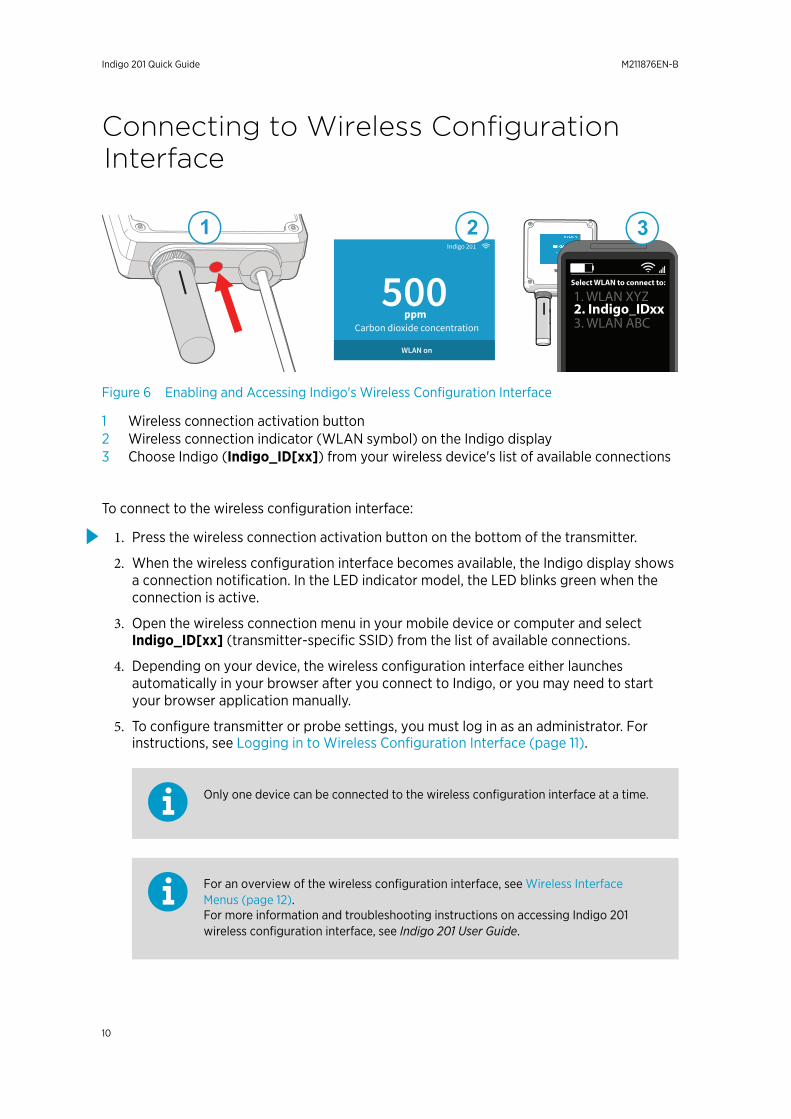
Figure 6 Enabling and Accessing Indigo's Wireless Configuration Interface
1 Wireless connection activation button2 Wireless connection indicator (WLAN symbol) on the Indigo display3 Choose Indigo (Indigo_ID[xx]) from your wireless device's list of available connections
To connect to the wireless configuration interface:
1. Press the wireless connection activation button on the bottom of the transmitter.
2. When the wireless configuration interface becomes available, the Indigo display shows a connection notification. In the LED indicator model, the LED blinks green when the connection is active.
3. Open the wireless connection menu in your mobile device or computer and select Indigo_ID[xx] (transmitter-specific SSID) from the list of available connections.
4. Depending on your device, the wireless configuration interface either launches automatically in your browser after you connect to Indigo, or you may need to start your browser application manually.
5. To configure transmitter or probe settings, you must log in as an administrator. For instructions, see Logging in to Wireless Configuration Interface (page 11).
Only one device can be connected to the wireless configuration interface at a time.
For an overview of the wireless configuration interface, see Wireless Interface Menus (page 12).For more information and troubleshooting instructions on accessing Indigo 201 wireless configuration interface, see Indigo 201 User Guide.
Indigo 201 Quick Guide M211876EN-B
10
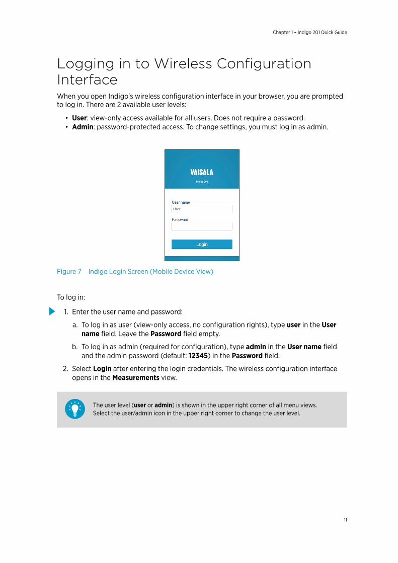
Logging in to Wireless ConfigurationInterfaceWhen you open Indigo's wireless configuration interface in your browser, you are prompted to log in. There are 2 available user levels:
• User: view-only access available for all users. Does not require a password.• Admin: password-protected access. To change settings, you must log in as admin.
Figure 7 Indigo Login Screen (Mobile Device View)
To log in:
1. Enter the user name and password:
a. To log in as user (view-only access, no configuration rights), type user in the Username field. Leave the Password field empty.
b. To log in as admin (required for configuration), type admin in the User name fieldand the admin password (default: 12345) in the Password field.
2. Select Login after entering the login credentials. The wireless configuration interfaceopens in the Measurements view.
The user level (user or admin) is shown in the upper right corner of all menu views.Select the user/admin icon in the upper right corner to change the user level.
Chapter 1 – Indigo 201 Quick Guide
11

Wireless Interface MenusIndigo transmitters are configured using a wireless browser-based configuration interface (requires a mobile device or computer with IEEE 802.11 b/g/n WLAN wireless connectivity). In addition to probe and transmitter configuration and calibration, you can also use the wireless interface to view measurement data and status information.
1
2
3
4
5
Figure 8 Wireless Configuration Interface, Desktop Browser View
1 Measurements: displays the measurement data of the connected probe2 Status: contains information about the status of Indigo and the connected probe (for
example, notifications and alarms)3 Calibration: calibrate and adjust probes using references. Available options (for
example, adjustment points) vary depending on the probe model.4 Settings: contains options for configuring the connection and display settings, outputs,
relays, probe-specific settings, and general device preferences
• General submenu: device information and general settings, wireless connectionand display settings
• Outputs submenu: configuration options for analog outputs 1-3• Relays submenu: settings for controlling relays A and B• Probe submenu: probe-specific settings such as environmental compensations and
filtering factor, probe calibration PIN code entry5 Main display area for menus and measurement information (desktop browser example)
Indigo 201 Quick Guide M211876EN-B
12


www.vaisala.com