v,4 and ibrtionz 'diges 144 - apps.dtic.mil
TRANSCRIPT
W V
4-- A -OIA~O OF
V,4 .4.
AND IBRTIONZ'DIGES DEC 144
22*
4 ~. 'A FFUCICE OF
T NICE WE VWA? ECREAR
,l NAAFUEUNA ORRSAC4AND
rpo fo ~*r@m %fifnw

THE SHOCK AND VIBRATION DIGEST-z - ' '4
Volumne 14. No. 11
STAFFNoebr16$1HOCKAND VIBRATIOn VOUaTIONCEol
EDITORIAL ADVISOR: Henry C. Pulay
VIBRATION INSTITUTE
TECHNICAL EDITOR: Ronald L. Edsai
-EDITOR: JudIthNm adbm
RESEARCH EDITOR: 'Mide L Tass~~f
*PRlODUCTION: Deborah It. H-Owud
BOARD OFEDITORS R. DedmAr W.D. PlIkey
R.L Sort E. SevinA publton of .J.D.C. Cria J.G. Showalter
DJ.Jlwm *.J Skop --
THE SHOCK AND VIBRATION K.E.-McKac Rjl.VolhiINFORMATION CENTER C.T. Morrow:, HkvnOisvka -
Code OM Nt4a Reerch eb orstry ~v
II.b -o -- neo ete.TM 1. A'- 's1 1
-. o '. eimefor pblsallon 11MI01116. ombn mShwlm .4"
Dr. .
CWpl of - uuin moflt sme I rbei mwm* anms Vibrati*~ nformumen Center ImucIp for thea enead by IVIC). Inqublet *mul be
diracled! to library resources. sithOr. Or the original publdirs
This p erida Is for sale on wafeitlion at an annua rate of $ 140.00. Forforeig sabecibas. there Is an ad doa 25 peret chug for overmiam delly-mry on both reapier suecrlption ad back Ieames Submcriptions we ecaIfor the iar vwr beginIng with the January tnAs. Back ilae we aveRl-Wie -Valsmee 9 throught 12 - for $20.00. Orders may be forwarded at any
times to SVIC. Code 5604 Naval Romelar LOraory. Wmhlngton. D.C.20375. lenience of this periodca Is approve In -eomne mWith the Depert-mont of the Navy Publications and Printing Regulations. NAVE XOS P-35.
SVIC NOTES
CORPORATE MEMORY
I think there is a problem today with the corporate memory of the shock andvibration community. Consider what today's retiree has seen in the last 35 to 40years. There has been a continual evolution of higher technology based systemssuch as missiles, jet engines, satellites, manned spacecraft, supersonic aircraft andhardened strategic structure. With each technical increase, there has been a con-comitant increase in the severity of the dynamic environments. Materials, such ashigh temperature alloys, orgar, -. )nd metal matrix composites and elastomeric(damping) compounds, have been developed to withstand these more severe envi-ronments. Finally, the advent of the digital computer has forever changed the waywe analyze structures, process environmental data or perform tests in the environ-mental laboratories. I am not suggesting that an organization suffers an irreparableloss when someone retires who has personally witnessed these 40 years of develop-ments in shock and vibration technology. Rather, I am asking the question, "Exact-ly matr does an organization lose and how can they compensate for the loss?"
It is really a problem in information retrieval. Someone who has witnessed thedevelopments knows exactly which documents contain the most useful informa-tion; they probably have personal copies of some of these and/or a bibliographylisting them. They know which organizations or people made what developmentsand they know the names of many expertu in the field. In a word, they have astarting point for quick access to shock and vibration information generated overthe last four decades. The ability to easily access information is what is lost whenthey retire.
An organization can do several things to compensate for this loss. New employees,as well as old, should be able to capitalize on their organization's corporate mem-ory. Training programs for new employees should be established to help them learnhow to access the useful documents both inside and outside the organization. Theyshould be made aware of centralized sources of information, such as the Shockand Vibration Information Center (SVIC), or professional societies such as theIES, ASME, SAE, AIAA, etc. SVIC's resources include index's to the Shock andVibration Bulletin, literature reviews and monographs. The novice should beencouraged to attend the technical symposia organized by SVIC and to professionalsocieties. The preservation of "corporate memory" is enhanced by interactingwith their peers at such meetings. SVIC and the professional societies have beenworking on this problem directly for many years. The sum of their output standsas a good first approximation to the "corporate memory" of the shock and vibra-tion community.
to Ld tj 10J.G.S.
E00
Is50 . --.

EDITORS RATTLE SPACE
COPYRIGHT LAW - 19M
The copyright law of 1976 was suppoed to provide equity among authors, pub-lishers, and users of original works. After five years under this law It is time toevaluate its effects on the transfer of technology.
To date engineers have never been interested In the copyright process. Their timehas been freely given to generate technical information without direct compensa-tion - except for book royalties. That Is not to say benefits have not been receivedby engineers who publish regularly. Recognition, credits toward promotion, andsecondary advertising of one's capabilities are among the benefits accrued by engi-neers who take the time to publish their work. The copyright law did not greatlyaffect many engineers. Except for more forms and paper work the modus operandiof the engineer has not changed during the past five years. So why should we beconcerned about the law?
The people who are in the middle of the technology transfer cycle - the publish-ers - have the most to gain or lose with copyright laws. The free use of excellentcopying machines is a direct attack on the viability and profitability of publishersUsers of published material for direct profit, Including libraries, have eroded theposition of publishers. In fact a major lawsuit is now being pursued against acorporate library for failure to compensate a publisher for widespread employeecopying. It takes money to edit, print, and distribute magazines, journala, andbooks. Publishers cannot be satisfied with recognition and secondary benefitsderived by engineers. There must be an incentive to continue to Invst money intechnical publications, Without publishers there will be no technology transfer.Perhaps users should think about this fact when they copy a paper or book - asI have often seen happen.
Surveys conducted by the federal government have confirmed that copying hasincreased during the past five year There is no indication that compensation hasIncMad; therefore, it I business a usal, end the 1976 copyright law is notproducing the desired result.
What will happen in the future? All of us complain about the high cost of printedmateriel. But as the volume of material printed by publishers decreases (largelybecause of copying), the cost of publications will go up to defray the fixed costsof editing and printing. This means that If the copyright law is not strengthenedeither corporations alone will be able to afford books amd journls or publicationwill c ae because publishers will not be able to continue their efforts.
R.L.E.
2
APPROXIMATE TECHNIQUES FOR PLASTIC DEFORMATIONOF STRUCTURES UNDER IMPULSIVE LOADING, MI
W.E. Bakee
Abgraet Togla of thk rvbw on *p~kwdff tech- mate analysis methods for impulsive response arenique for padei daftnnatlon of stuczuw under available 114, 151.
-mk k~d rvswrd*n d snefrseq, deep-&*eed ws*ae and resevwit expevnenlL; A briefacociewiw conca, the review, nofewiea once 1979 v
ff4 We l1eo
This review updates two previous reviews on the sametopic in 1975.1) and 1979 (2]. It supplements theearlier reviews and covers only work reported since W
* 1979. The reader should acquire the previous reviewsfor a reasonably complete coverage of this speciealizedtopic.
RESEARCH.ORIENED ANALYSES
Most of the recent published papers on research- -. -- ' - joriented analyses are continuations or spin-offs of
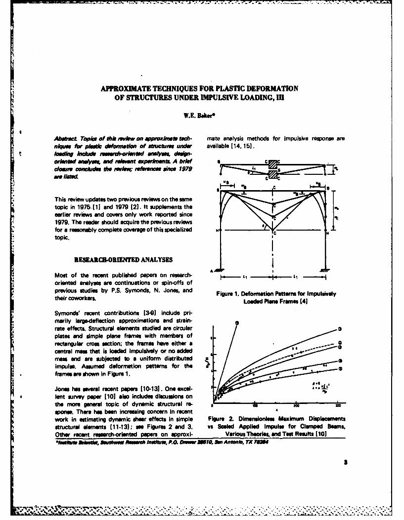
*previous studies by P.S. Symonds, N. Jones, and Figure 1. Deformation Patterns for ImpulsivelytheircoworersLoaded Plane Frames [41
Symonds' recent contributions 13-91 include pri-marily large-deflection approximations and strain-
4 rate effects. Structural elements studied are circular4 plates and simple plane frames with members of
rectangular cross section; the frames have either acentral mans that is loaded Impulsively or no addedmass and are subjected to a uniform distributedimpulse. Assumed deformation patterns for theframes are shown In Figure 1.
Jones has sevealI recent papers 110-131. One excel-* lent survey paper 1101 also includes discussions on
the more general topic of dynamic structural re- 0 kspone. There has been increesing concern in recentAwork in estimating dynamic shear effects in simple Figure 2. Dimensionless Maximum Displacementsstructural elements [11-131; we Figures 2 and 3. vs Sealed Applied Impulse for Clamped Beams,Other recent research-oriented papers on approxi- Various Theoris, and Test Results ( 101o*Iwatim bt,. Saeutueu et I netU, P.O. Onmr =51,SlP Aftwis, TX YOU
.4 .~ .. ....

current discussion of the use of energy-balance meth-ods has been published 1161, as has a compilation
* of a number of dosed-form deformation predictionformulas that can be specialized to impulsive loads[17). A number of these formulas are given in the
2table.
2. -Scaled P-i diagrams for rapid estimation of maximumSPL response of blast-loaded structural elements have
Abeen published [16]. Figure 4 is typical of a set ofcurves for beam elastic-plastic bending. Each curverepresents the loci of combinations of scaled applied
A premre and applied specific impulse that yield the
seine maximum response. Both maximum strain andFigure 3. Dimensionless Maximum Displacements deformation can be obtained for a variety of bound-vs Scaled Applied Impulse for Fully Clempec Rectan- ary conditions by using values inset in the figure.gular Plates, Various Theories, and Test Reuits I101
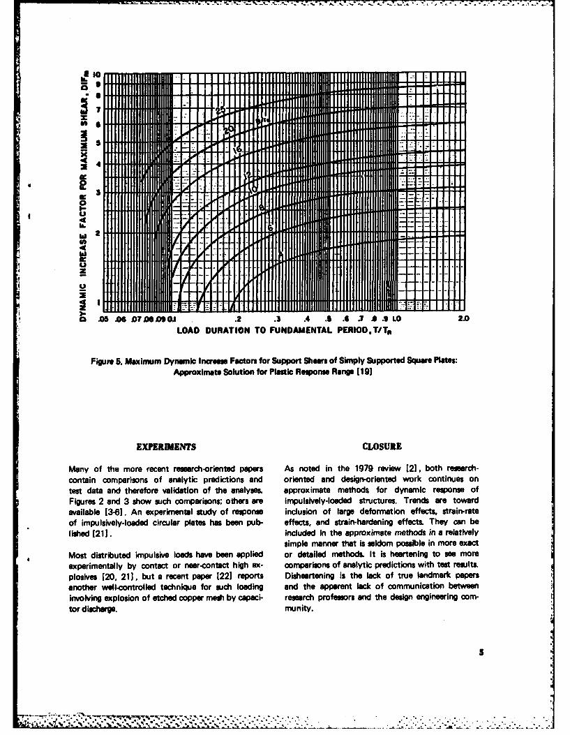
The interest in dynamic shear effects evidenced inDESIGN.ORIENTED ANALYSES several research-oriented papers [10, 11, 131 is also
apparent in design-oriented work. Studies on dynamicThe use of energy-balance methods to estimate the shear failure of reinforced-concrete slabs have beenmaximum deformations in Impulsively-loaded struc- reported [18. 191. A typical design graph is showntures has been discussed [1]. as has the concept of here as Figure 5. It gives dynamic increase factorsscaled P-i diagrams for rapid estimation of maximum for sheer (compared to maximum shear stresses underresponse of dynamically-loaded structures 121. the seie applied peak pressure B) for slabs of differ-
-II
Work has continued on these two topics. A complete ant strengths and stiffnesses
inutlliw 3. 1)11811 S. 6 1 iii
.43
lliflE "Z"
.1. CCo
W2 pb.A2
tP *yZFigure 4. Elastic-Plastic Energy Solution for Bending of Blast-Loaded Beams [16
,.. ..... .... ....... .... ............ .. .. . . -.. ..
*10
.--
4'
0 -
I _
7 &
4
Wo 0
z 0
A-
SAS .06 07 .9OJ .24 3 A .5 .. 3 .ILO 2.0LOAD DURATION TO FUNDAMENTAL PERIOD.T/Tn
Figure 5. Maximum Dynlmic Increase Factors for Support Shears of Simply Supported Square Plates:Approximate Solution for Plastic Response Range [191
EXPERIMENTS CLOSURE
Many of the more recent research-oriented papers As noted in the 1979 review [2], both research-contain comparisons of analytic predictions and oriented and design-oriented work continues ontest data and therefore validation of the analys. approximate methods for dynamic response ofFigures 2 and 3 show such comparisons; others are impulsively-loaded structures. Trends are toward
available [3-61. An experimental study of response inclusion of large deformation effects, strain-rateof impulsively-loaded circular plates has been pub- effects, and strain-hardening effects. They can be
lished f21]. Included in the approximate methods in a relativelysimple manner that is seldom possible in more exact
Most distributed impulsive loads have been applied or detailed methods. It is heartening to see moreexperimentally by contact or near-contact high ex- comparisons of analytic predictions with test results.plosives [20, 211, but a recent paper [221 reports Disheartening is the lack of true landmark papers
another well-controlled technique for such loading and the apparent lack of communication betweenInvolving explosion of etched copper mesh by capaci- research profesors and the design engineering com-tor discharge. munity.
5
.40
ftfm
40rm 4
06 .06
9a s I I r~ Is

I it Dl-4
w w
Il a a m a 0 "I a 0
a S. S. S S.
if33 3 3.- 4 *
al El El r) G z
ez CdePJ.

I. 3.3 3
q. Od 0~
aA f I; b13 I
a t
** 1aU a
w m, m
3A 3
IA'-l I X . U -5 k
SM.C
DEFINITION OF SYMBOLS
ENGLISH T load duration
A beam cross-sectional area T n natural elastic periodAi area loaded by specific impulse Vo impulsive velocity
B peak blast loading pressure w lateral deflection of a beam or plate atany point
b loaded width of beam
DIF dynamic increase factor for maximum center deflection of a beam or plateshear X short semi-span of a plate
E material elastic modulus x distance along the beam or plate,normally measured from the center
Et tangent modulus for strain-hardeningmaterial Y long semi-span of a plate
G mass attached to plane frame y distance along plate centerline mea-sured from the plate center
H thickness of plate, or shellZ plastic section modulus
second moment of area of a cross-sec-tion; total impulse
i specific applied impulse
Te (i2b2f3/pAEI)34, scaled specific im- GREEKpulse for elastic response
X/YSp (ib2 f/pAMoJ , scaled specific im-
pulse for plastic response r (3- 2o)[I - to+ 1/(2- to)1/6
k ratio of attached mass to frame cross- ey yield stressmember mass = G/p~bH S 4i1 £=/OyH 4
9 length of beam for which the deforma-tion is being determined; length of V Poisson's ratiocylinder
M beam plastic moment mPp material density
P y axial yield force of the beam = Acy
R mean radius of a sphere or cylinder,radius of a circular plate *e boundary condition factor for strain
r radius to arbitrary point on a circular i boundary condition factor for specificplate impulse
ru dynamic ultimate flexural resistance Op boundary condition factor for pressure
tAR radial expansion of a cylinder or a boundary condition factor for max!-sphere 0 mum deflection
9
S° . ......,. ." : ° ° ' .. o,. -, o ° o°. o - .% . . . . . . . .

I I . . , . .. . .. - . .. . " .. "- "- - . ". ". - . .. "- "- " . . . . .
REFERENCES
1. Baker, W.E., "Approximate Techniques for 11. Jones, N. and Gomes de Oliviera, J., "The In-Plastic Deformation of Structures under Im- fluence of Rotatory Inertia and Transverse Shearpulsive Loading," Shock Vib. Dig., 7 (7), pp on the Dynamic Plastic Behavior of Beams,""::107-117 (1975). J. Appl. Mach., Trans. ASME, 46 (2), pp 303-310
(1979).2. Baker, W.E., "Approximate Techniques for
Plastic Deformation of Structures under Im- 12. Jones, N. and Guedes Soares, C., "Higher Modalpulsive Loading, I1," Shock Vib. Dig., 11 (7), Dynamic Plastic Behavior of Beams Loaded Im-
. pp 19-24 (1979). pulsively," Intl. J. Mech. Sci., 20, pp 135-147(1978).
3. Symonds, P.S. and Chon, C.T., "Finite Visco-plastic Deflections of an Impulsively Loaded 13. Gomes de Oliviera, J. and Jones, N., "Some Re-Plate by the Mode Approximation Technique," marks on the Influence of Transverse Shear onJ. Mech. Phys. Solids, 27, pp 119-133 (1979). the Plastic Yielding of Structures," Intl. J. Mech.
Sci., 20, pp 759-765 (1978).4. Symonds, P.S. and Raphanel, J.L., "Large De-
flections of Impulsively Loaded Frames - Simple 14. Ponter, A.R.S., "Dynamic Behavior of StructuresExtensions of the Mode Approximation Tech- Composed of Strain and Work Hardening Visco-nique," Inst. Phys. Conf. Ser. No. 47: Chapter Plastic Materials," Intl. J. Solids Struc., 16, pp3, Inst. Physics, pp 277-287 (1979). 793-806 (1980).
5. Symonds, P.S. and Chon, C.T., "Large Visco- 15. Lepik, 0., "Optimal Design of Rigid-Plasticplastic Deflections of Impulsively Loaded Plane Simply Supported Beams under ImpulsiveFrames," Intl. J. Solids Struc., 15, pp 15-31 Loading," Intl. J. Solids Struc., 17, pp 617-629( 1979). (1981).
6. Symonds, P.S. and Wiersbicki, T., "Membrane 16. Baker, W.E., Cox, P.A., Westine, P.S., Kulesz,Mode Solutions for Impulsively Loaded Circular J.J., and Strehlow, R.A., Explosion Hazards andPlates," J. Appl. Mech., Trans. ASME, 46 (1), pp Evaluation, Elsevier Scientific Publishing Co.,58-64 (Mar 1979). Amsterdam (1982).
7. Symonds, P.S., "Elastic, Finite Deflection and 17. Cox, P.A., Westine, P.S., Kulesz, J.J., and Es-Strain Rate Effects in a Mode Approximation parza, E.E., "Analysis and Evaluation of Sup-Technique for Plastic Deformation of Pulse pressive Shields," Edgewood Arsenal ContractorLoaded Structures," Rep. ENG 77-11874, Div. Rept. ARCFL-CR-77028, Rept. No. 10, FinalEngrg., Brown Ur-iversity (Dec 1979). Tech. Rept., Edgewood Arsenal, MD (Jan 1978).
8. Symonds, P.S., "The Optimal Mode in the Mode 18. Murtha, R. and Crawford, J., "Dynamic FailureApproximation Technique," Report ARO 79/1, Predictions of Shallow-Buried Reinforced-Con-Div. Engrg., Brown University (Dec 1979). crete Slabs," TM No. M-51-81-04, Civil Engrg.
Lab., Port Hueneme, CA (May 1981).9. Symonds, P.S., "Finite Elastic and Plastic Defor-
mations of Pulse Loaded Structures by an Ex- 19. Stea, W., Dobbs, N., and Sock, F.E., "Sheartended Mode Technique," Report ARO 79/2, Respone of One- and Two-Way Elements Sub-Div. Engrg., Brown University (Jan 1980). jected to Blast Loads," CR 81.010, Civil Engrg.
Lab., Port Hueneme, CA (Mar 1981).10. Jones, N., "Response of Structures to Dynamic
Loading," Inst. Phys. Conf. Ser. No. 47: Chapter 20. Bodner, S.R. and Symonds, P.S., "Experiments3, pp 254-276, Inst. Physics (1979). on Viscoplastic Response of Circular Plates to
10
---------------------- . " . " '

Impulsive Loading," J. Mech. Phys. Solids, 22. Forrestal, M.J., Sagartz, M.J., and Tucker, W.K.,
27, pp 91-113 (1979). "Impulse Loading with an Electrically ExplodedEtched Copper Mesh," Intl. J. Solids Struc., 16,
21. Wenzel, A.B. and Baker, W.E., "The Use of pp 473-477 (1980).Light-Initiated Explosives for the ImpulsiveLoading of Structures," Inst. Environ. Sci.,1970 Proc., pp 142-150 (Apr 1970).
11
survey and analysisLITERATURE REVIEW: Vibratiolteatr
The monthly Literature Review, a subjective critique and summary of the litera-ture, consists of two to four review articles each month, 3,000 to 4,000 words inlength. The purpose of this section is to present a "digest" of literature over aperiod of three years. Planned by the Technical Editor, this section provides theDIGEST reader with up-to-date insights into current technology in more than150 topic areas. Review articles include technical information from articles, reports,and unpublished proceedings. Each article also contains a minor tutorial of thetechnical area under discussion, a survey and evaluation of the new literature, andrecommendations. Review articles are written by experts in the shock and vibrationfield.
LThis issue of the DIGEST contains articles about spalI fracture of soids and optimalvibration reduction over a frequency range.
Professor D. Kratcinovic of University of Illinois at Chicago has written a summaryof general features of material fracture and crack propagation. Analytical methodsare reviewed. Passive and active models are described and compared.
Dr. W.D. Pilkey, Mr. L. Kitis, and Dr. B.P. Wang of University of Virginia, Char-lottesville, Virginia have written a review of optimal vibration reduction techniquesfor systems subject to harmonic excitation over a frequency range. Only passivemeans of control are considered. The objective functions used for optimization arerestricted to those that relate directly to some measure of frequency response.
12
Dr WD.. Pleyr L iis n .. P. Wago-nvriyo igna hr
SPALL FRACTURE OF SOLIDS
D. Kruiaovic
Abswt This .tkle contam a wmmenr of Pnel The growth of microcracks under the influence ofAeltue of ma1ol fAWre and cck propaetion dynamic loads, now known as sWalling or scabbing,Ans&/tal methd aw reviewed. a and actiw was apparently first noticed and examined by Hop-model are dowbed and compoied kinson during the 1920s. The military applications
associated with the design of projectiles and armorhas provided impetus for the study of spalling during
In the most general case the energy imparted to a the past 40 years.body by some external source can be: used forrigid body motion, stored as elastic strain energy, Spelling is defined here as a mode of material frac-
and dissipated by a change of phase or some other ture associated with the interaction of unloading
type of permanent (irreversible) rearrangement of (tensile) stress waves It occurs in connection with
crystalline microstructure. impacts (collisions), explosive blasts, intense radia-tion, or electric pulses. The magnitude and durationof the tensile pulse are functions of the load-timeThis review dals with Wpall fracture of solids in a
somewhat restricted sense. The m problem can b~e history, geometry, and material properties of the
studied within the wider context of shock-wave structure and the support conditions (boundaryphysics or the shock compression of solids [1). conditions).This review focuses on phenomena characterized bystress levels that are typically in the range of rupture GENERAL OBSERVATIONSor yield stress. The pressures associated with signifi-c-nt shock compressions are commonly 10 to 50tieshock compresinstre. cThe main reason for the diffuse pattern of cracks intimes larger in magnitude. dynamic loading is a disparity in the velocity of
crack propagation (cca 2000 m/sec for metals) andAmong the several ways in which crystalline struc- the velocity of stress wave propagation (typicallyture can be changed, the following are discussed in up to 7000 m/sec). A stress level that providesthis article: change in the pattern of linear defects sufficient energy to cause crack growth will change(dislocations) resulting in what is commonly per- before the crack has a chance to acquire its criticalceived as plastic flow and evolution of a population size. Hence, degradation of the material can varyof planar and spherical microcracks (or microdefects) gradually in space and time from complete sepera-arising typically at impurities or grain boundaries. tion (fragmentation) to a level virtually indistinguish-
able from the virgin material.
Dislocations resulting in plastic flows are typical ofductile metals and rubber-like materials; they occur The metallurgical aspects of palling have been re-during slowly applied loads and at high temperatures. viewed (1, 21. The damage in a majority of casesA material that undergoes Impulsive loads of short occurs around defects in the material, thus implyingduration and high Intensity typically develops a that damage is a process of activation rather thanlarge number of small (or micro) cracks; these cracks nucleation.are distributed In a fairly homogeneous manner overa finite part of the solid. (The crack is usually con- In highly pure materials spell damage is associatedsidered small If its size is less than that of a grain.) with either I111 1 (aluminum monocrystals) or
oe1%%e, CAi Englnwng, Melaiham and Metiurv, Unkferlfty of lhiea at Chls, Bax 4M4Il Chkso, IL
Is
1 0 0 } planes (brittle materials). In the case of The analyses in both reviews are based on the propapolycrystalline materials damage propagates in both gation of stress waves through an ide.".y elastic solid.inter- and trans-granular modeL In materials with The incident wave produced by collision or explo-a large number of impurities and defects the initial sion is typically compressive. After it is reflecteddistribution of cracks has a random orientation. The from a free boundary, the wave is transformed intodeterioration propagates, in all likelihood in a random a tensile wave. When the tensile stresses exceed car-fashion, until one of the crack systems - typically tain threshold values, spelling occurs; i.e., loss ofone perpendicular to the principal tensile strain - integrity perpendicular to the axis along which thebecomes dominant and begins to control the subse- tensile wave propagated.quent material response. The remainder of the cracks
* remain dormant until and unless the direction of the A series of similar papers has appeared in the last twotensile stress changes. When a large number of micro- decades in the Soviet Union. A common characteris-
* cracks are activated, the process can be described tic of the papers is an either-or proposition accordingin a statistically smoothed sense using the methods of to which "the transition of the material into a pow-continuum mechanics. The cracking of concrete Pnd dory medium takes place instantaneously on a certainespecially geotechnical materials is also a function of (moving) surface dividing the undamaged regioninitial damage, and the same principles are valid, from the fragmented region" [71. In other words
a solid body is divided by a moving surface (shock
,he detection of microdefects such as cracks and front) into two parts. Part of the volume already
voids is a fairly routine task. For example, the volume traversed by the moving front is pulverized; the
of spherical voids of a material can be measured remainder, of the solid is still in its virgin state. Ac-
simply by weighing a specimen in air and in liquid cording to this purely mathematical artifice spalling
and comparing the weights with a virgin piece of the is an instantaneous process in which a solid is trans-formed from one extrernal state into another. Al-
same volume of material [3]. It is also possible tocount the number of voids par unit area on a micro- though such a stratagem is convenient analytically,
graph (3]. More exotic methods, such as small angle it contradicts both physical intuition end overwhelm-neutron scattering [41, acoustic emission 151, and ing experimental evidence to the contrary.ultrasonic testing, were successfully used in the past.It is in principle possible to measure the damage on The debate on selecting a fracture criterion ascribedthe surface of a body and associate the surface dam- to a moving discontinuity front has been summarized
.* age density to the volume damage density in a probe- (8]. Various authors have proposed at least six dif-bilistic manner. ferent models. They differ in the definition of the
nature of the (crushed) material traversed by themoving front - definitions range from ideal incom-pressible and compressible fluids to an ideally plastic
ANALYTICAL METHODS solid - and in the selection of the splling conditionon the moving discontinuity front - conditions range
" Early Work from threshold values of stress and energy to velocity- Most of the early work on spalling has been suc- of the fracture wave. In view of the fact that experi-
cinctly summarized 12, 6). In one review 161 the mental evidence does not support any of these as-material is considered to be purely elastic even at sumptions, it is redundant to discuss the purporf dthe incipient spall. The other paper [2] examines merits or demerits of the suggested models.the influence of the pulse shape (i.e., its time history)and its duration on the location and extent of dam- Several other similar models have been discussed [9].age. An important and often overlooked conclusion In addition, some empirical and semiampirical designis that damage cannot be satisfactorily predicted procedures associated with the design of bombunless a complete description of the stress history at shelters have been summarized [10-121.a particular cross section is available. The authorsalso point out that a fracture cannot be instantaneous Damage Theoriesbecause it is dependent on the rate at which cracks The lack of a variable to define the level of damagecan be nucleated and propagated. locally both qualitatively and quantitatively is the
14
" -- .. - , , . .- .. ; ... .-. ... ". '.
essential shortcoming of the methods mentioned According to a different approach [151 the time toabove. In the absence of such a variable. which must failure can be computed from strm a asbe a function of space and time, Walling must indeedbe arbitrarily defined as an instantaneous transition tR - to exp [(Uo - 'a)/kT]between two extremes - from virgin material tototally fragmented medium. And yet damage during where k and T are the Boltzmann's constant anddynamic fracturing, measured for example by the temperature; to, Uo , and y are material constantsdensity of microcracks, is obviously a continuous related to the atomic vibration period, bindingfunction of time. The site at which total separation energy of atoms, and the level of lattice disorderoccurs is typically embedded in a region where crack respectively.density has reached a considerable level. Macro-scopically, spelling is a well defined orderly process AWA, meda Neglecting the Influence of damageconsisting of a measurable and identifiable sequence on such macroscopic parameters of the material asof events; i.e., nucleation, growth, and coalescence of density and elastic moduli simplifies the problemmicrocracks into a macrocrack. The fast is that the enormously because the stresses and strains can betime scale is compressed such that the events cannot determined on the basis of the propagation of wavesbe seen. in an elastic medium. This is the major shortcoming
of every passive model. The speed at which the wavesIn order to describe a process characterized by a propagate, the pulse shape, and the energy are sub-gradual, time- and space-dependent degradation of stantially altered by the damage-changed proper-material it is necessary to introduce a variable that ties of the material; i.e., the sharp wave fronts arereflects in an acceptable manner the distribution and smoothed, the pulse durations are generally Increased,density of microdefects in the material. Models speed of propagation is lowered, and the energy Is
that suggest a specific interdependence of the stress diminished through dissipation. Experimental ob-and strain field on one side and the demage field on servations unambiguously relate the extent of damagethe other side can be classified as either passive or to the duration and magnitude of the tensile pulse;active models 1131. predictions based on pasive models re thus of ques-
tionable reliability. A reliable model should considerWith passive models the level of damage, or material the interaction of damage level and stress fields; i.e..degradation, is determined on the basis of stresses the redistribution of stresses and strains due to theand strains computed for the virgin material; that is, gradual change of the material properties as damagethe unmodified material. With active models the accumulates. In view of the gradual and continuousstress and damage fields interact and modify each change of material properties as functions of stressesother. Available experimental evidence strongly and strains a solution of the wave propagation prob-
supports the results obtained using active models. lem requires special and complex computer codes.The stress pulse undergoes significant changes asthe microcracks in the material grow. Because the In the last decade a powerful active model for spelling
level of damage strongly depends on the pulse shape anelysm that utilizes experimental procedures has12), passive models provide les than reliable predic- been developed 1161. The model is applicable to thetion whenever damage is substantial, analysis of dynamic fracturing of both brittle and
ductile materials and even the occurrence of shearPaw@ modlef One of the best known passive models bend instabilities; the model is in the form of ais the Tuler-Butcher model [141 according to which sequence of special computer codes rather than in adamage depends on the entire stress history conventional continuum mechanics form.
t XD"a toA[e(t) - oO] dt Fracture in the case of ductile materials is assumedto occur by nucleation and viscous growth of nearly
A, vO, and are the material parameters. The damage spherical voids 1161. The experimentally observedvariable D is somewhat loosely defined either as the surface distribution of voids is by means of a specialdegradation of strength or as a number of observable computer program related to the volumetric distribu-
cracks. tion of voids. Rate lews that govern the nucleation
15
,% , -- ,-,. ,, .-. ,, ,--, -. *..,, .- -- - ,- . .- • - - . ..- ...-. . .:. ., .. .. .... .. .... .o.- . ..... . " - . - i- . •- -i _ I, ,
,F.
of new voids and the viscous growth of existing crack growth was introduced 120). Other linearvoids are formulated on the basis of some passive cases have been studied 1211.models in terms of the tensile premure obtained fromthe Mie-Gruneisen equation for the material.
• ' SUMMARYA fracture is assumed to be brittle whenever damageconsists of penny-shaped cracks. In this cae observed
f sdaAt present it is probably safe to state that the prob-: surface cracks are organized into groups according tothe size and orientation; cracks are then transformed lem of spelling requires significant further develop.thesiz an orenttio; racs ae ten ranfored ment. Elementary methods based on elastic vwstatistically into a volumetric distribution assuming mrnt.gElemenary methobased sic wav* axal ymmery roun th axi oftensle ave propagation are, in all probability, sufficient for
axia symety arundtheaxi of ensle ove general analyses during design. Future developmentpropagation. Special rate equations have been pro- gnl alysfsvdrin in.uFuturendevelopmentposed for crack nucleation and growth. Fragmenta- will probably favor continuum mechanics theoriestion is onsidered to be the extension of crack The establishment of a comprehensive theory, despite
growth; i.e., a final stage of interaction and coales- recent theoretical advances, is far from complete. Acence of microcracks. The computations performed better understanding of damage evolution laws, strainr atee in lu n c s cra ckrc s p r o p a g ati onas p e dpa ndfe sma
* for one- and two-dimensional geometries compare rate influences, crack propagation speed, and estab-
admirably well with experimental data for a wide lishment of an effective wave propagation code arrange of materials, including aluminum, steel. iron. some aspects of the problem that will demand strongcopper, and polycrbonates u efforts. The importance of the problem is sufficient
guarantee that such efforts will be forthcoming.In the early 1970s a conventional analytical modelbased on thermodynamics with internal variableswas developed [17, 18). Damage was assumed to ACKNOWLEDGMENTconsist of small, independent (non-interacting) cracksdistributed in brittle materials and spheroidal voids This work was supported by a U.S. National Science
* in ductile materials. In one case [171 damage was Foundation grant to the Univeristy of Illinois atdefined by a vector normal to the cracks and of a Chicago Circle.magnitude equal to the relative void area. Withspheroidal cavities the damage variable is a scalar.Damage evolution laws are formulated on the basis REFERENCES
, of existing material science passive models. Therigorous thermomechanical constitution of this 1. Davison, L. and Graham, R.A., Physics Report.model is conducive for future development. 1. (4), pp 256-379 (1979).
A modification of this model, which contains theoriginal Kachanov's damage theory as a special case, 2. Butcher, B.M.. Barker, L.M., Munson, D.E., andwas proposed by Krajcinovic and Srinivasen [19j Lundergan, C.D., AIAA J.,2. pp 977-990 (1964).during a study of the dynamic fracturing of concrete.Instead of postulating an arbitrary damage law, 3. Snowden, K.U., Stathers, P.A., and Hughes, D.S.,the damage criterion is derived from the associated Res. Mechanica, 1, pp 129-147 (1980).flow potential, similar to the yield condition in thetheory of plasticity. This approach rests on firmer 4. Page, R., Weertman, J.R., and Roth, M., Scriptatheoretical grounds and facilitates studies of cyclic Met., 14, pp 773-777 (1980).loads and rotating stress fields. It is also of interestthat the thermodynamic force conjugate to the 5. Pollock, A.A., Proc. First Conf. Acoustic Emis-damage variable is related to the crack resistance sion/Microseismic Activity Geol. Str. and MatI.,force, or the energy release rate - stress intensity ed. H.R. Hardy, F.W. Leighton, Trans Techfactor, used in fracture mechanics. Publ., pp 383403 (1977).
Some essentially linear cases have been studied in 6. Rinehart, J.S., Stress Transients in Solids, Hyper-which the inertial effects associated with the fast Dynamics, Santa Fe (1975).
16
. . ...... ... ............. . .........
. ." . -- . "-" * -. "-. - . .-... ,:'.o;1-. .. . -
7. Slepyan. L.I. and Troyankine, L.V., Izv. AN 14. Tuler, F.R. and Butcher. B.M., Intl. J. FractureSSSR, MTT,.A, pp 63-72 (1969). Mech., 4. pp 431-437 (1968).
8. Slepyan, LI., Izv. AN SSSR, MTT, 12, pp 181- 15. Zhurkov, S.N., Intl. J. Fracture Mech.,2, pp 311-186(1977). 322 (1966.
16. Seaman, L., Curran, D.R., and Shockey, D.A.,9. Kachan, M.S. and Trishin, Vu.A., Zhurna! Prikl. J. AppI. Phys., 47, pp 4814-4826 (1976).
Mekh. I Tekhn, Fiziki, pp 114-124 (1977).
17. Davison, L and Stevens, A.L., J. Appl. PhyL,10. Dept. of the Army, "Structures to Resist the 44, pp 668-674 (1973).
Effects of Accidental Explosions," TM5-1300,U.S. Govt. Printing Office. Washington, DC 18. Davison, L., Stevens, A.L., and Kipp, M.E.,(1962). J. Mech. Phy. Solids. 25, pp 11-28 (1977).
19. Krjcinovic, D. and Srinivasan, M.G., Proc. 35th11. Dept. of the Army, "Fundamentals of Protective Meeting F, Symp. imeDnentFailure
Design (Non-Nuclear)," TM5-855-1, U.S. Govt. Meeting MFPG, Symp. Time-Dependent FailurePriningOffie, ashigto, DC(196).Mach. Assessment Methodology, Natl. BureauPrinting Office, Washington. DC (1965). SdGihrhrM 18)
Stds., Gaitherslburg, MD (1982).
12. Natl. Defense Res. Com., "Effects of Impacts 20. Passman, S.L., Grady, D.E., and Rundle, J.B..and Explosions," Summary Tech. Rep., Vol. 1, J. Appl. Phys..2, pp 4070-4075 (1980).AD221586, Washington, DC (1946).
21. Krajcinovic, D., Srinlvasan, M.G., Fonwka,13. Curran, D.R., Seaman, L., and Shockey, D.A., G.U., and Valentin, R.A., ASCE Preprint 80-522.
Physics Today, 0,pp 46-55 (1977). ASCE Convention, Florida (1980).
17
OPTIMAL VIBRATION REDUCTION OVER A FREQUENCY RANGE
W.D. Pgey, L Kitis", and L.. Wang
Abstract. This is review of optimal vibration redue- first analysis of the absorber is usually attributed todo tchniuee for systems ubject to harmonic Ormondroyd and Den Hartog [1]. A detailed dis-excitation overa frequency rane. Onlypemw mis cussion of optimal tuning and damping parameters isof control are conukbred The objectiaIv funetior given in Den Hartog's book (21. The followingused for optimization are reastritod to hoe that symbols are used to write the equations of motionrelate directly to sw mesure of frequency re- in a dimensionless form.
onM. Oher common optimization loals such aweit minimization with Anpone constraints we Xst = F/k, = static displacement of mainnot incudd in this survey, mass produced by a force F
i=m 2 /m, = mass ratio - absorber masw/CONVENTIONAL DYNAMIC VIBRATION main mass
ABSORBER
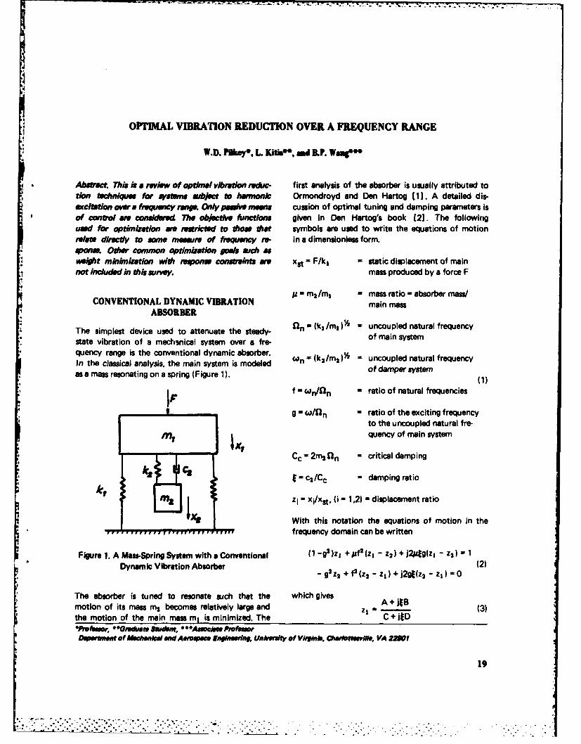
The simplest device used to attenuate the steady- fln (k, /m) - uncoupled natural frequency
state vibration of a mechsnical system over a fre- of main system
quency range is the conventional dynamic absorber.
In the classical analysis, the main system is modeled ('On - (klm 2 )3 = uncoupled natural frequency
as a mass resonating on a spring (Figure 1). of damper 1stem
f - Wn/1'n = ratio of natural frequencies
g = w/fln - ratio of the exciting frequencyto the uncoupled natural fre-
#1 quency of main system
Ccin2mg n - critical damping
k M = C2/C c = damping ratio
- xi/xst, 1i - 1.2) - displacement ratio
With this notation the equations of motion in the........ , ............ frequency domain can be written
Figure 1. A MawSpring System with a Conventional (1 -g2 )z1 + 1f02 (z - Z2) + j2Ag(z1 - Z2) 1Dynamic Vibration Absorber 2 (2)
- 9 Z2 + f2 U2 - zs ) + j2gt(z2 -z, ) =0
The absorber is tuned to resonate such that the which gives A + jJBmotion of its mass m2 becomes relatively large and z - (3)the motion of the main mass m, is minimized. The C + lED*Pofem, *Gne Studen, ""A* /cAe Preftao
eof AfeehwkI and A~voe Eogineehd, Unhkvlt of Virklnbh, Oafoetts, , VA 22Wf
19
.................... C"""...".'.'."......... i: ..- -; i
where EXTENSIONS OF TIlE CONVENTIONAL
DYNAMIC ABSORBERA -f 2 - g2
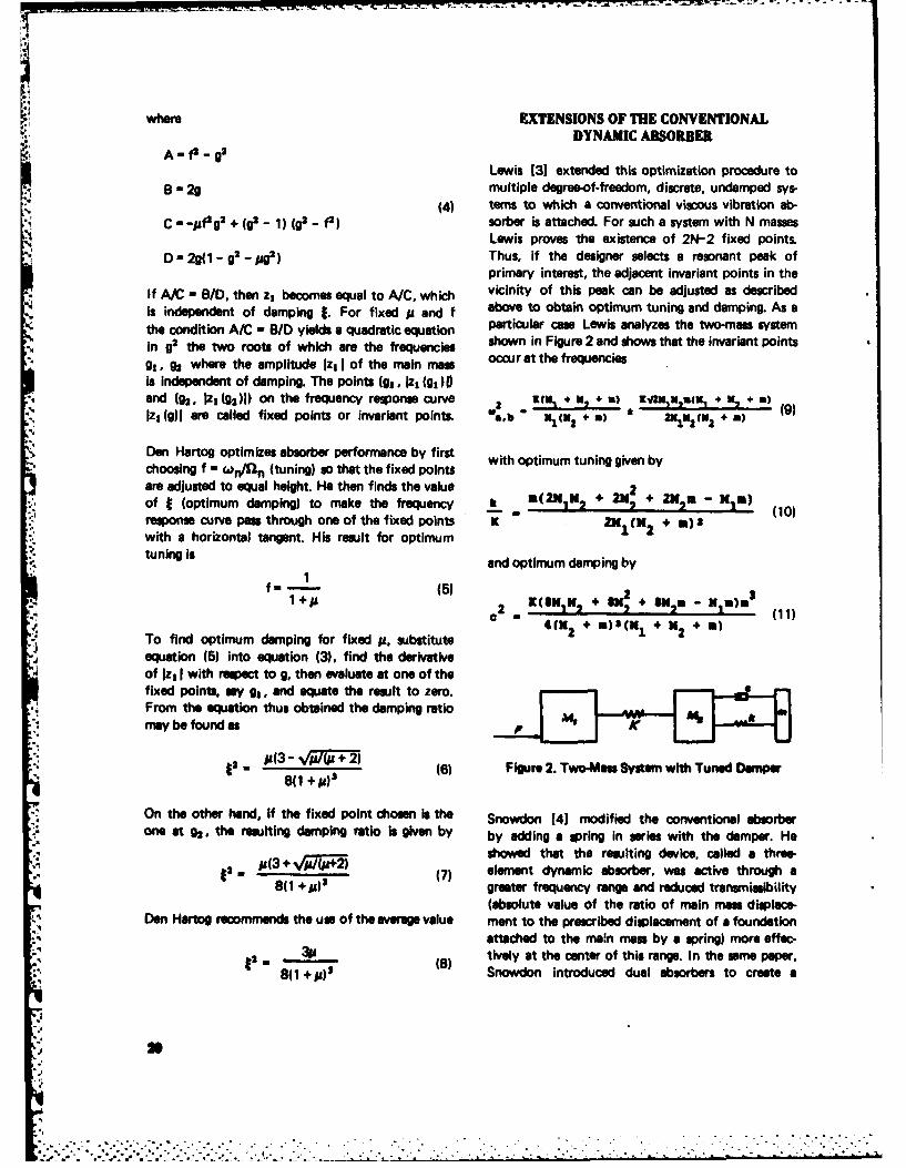
Lewis [31 extended this optimization procedure toB-2g multiple degree-of-freedom, discrete, undamped sys-
(4) terns to which a conventional viscous vibration ab-
C _"fg2 + (g -1) (g2 - f2) sorber is attached. For such a system with N massesLewis proves the existence of 2N-2 fixed points.
D-2g(1-g2-ag') Thus, if the designer selects a resonant peak ofprimary interest, the adjacent invariant points in the
If A/C - B/D, then z, becomes equal to A/C, which vicinity of this peak can be adjusted as describedis independent of damping 1. For fixed p and f above to obtain optimum tuning and damping. As athe condition A/C - B/D yields a quadratic equation particular case Lewis analyzes the two-mass systemin g2 the two roots of which are the frequencies shown in Figure 2 and shows that the invariant pointsg1 , g2 where the amplitude 1z, I of the main mass occur at the frequenciesis independent of damping. The points (g1 , Iz, (gl)I)and (1h. 1zn (g2)1) on the frequency response curve l 4 U u, ) ZqK x s ix1z, (g)I are called fixed points or invariant points. ,b 2 +m) 6 Z 5(-, (m) 9)
Den Hartog optimizes absorber performance by firstchoosing f - OCn/n (tuning) go that the fixed pointsare adjusted to equal height. He then finds the value 2of I (optimum damping) to make the frequency k m(2NIK, + 2, s, -10)response curve pas through one of the fixed points K K + a) (with a horizontal tangent. His result for optimumtuning is
and optimum damping by1
f = (5) 2 +lK)*22 (11)
To find optimum damping for fixed g, substitute C 4 .2 + (m I + 2 +
equation (5) into equation (3). find the derivativeof Iz, I with respect to g, then evaluate at one of thefixed points, say g , and equate the result to zero. -From the equation thus obtained the damping ratiomay be found as
+) (6) Fgure2. Two-Ma Systm wthTunedDonww* 811 +/51
On the other hand, if the fixed point chosen is the Snowdon 141 modified the conventional absorberone at 92, the resulting damping ratio is given by by adding a spring in series with the damper. He
* (3 showed that the resulting device, called a three-"2 . (3+ (7) element dynamic absorber, was active through a
8(1 +0)5 greater frequency range and reduced transmisibility(absolute value of the ratio of main man displace-
Den Hartog recommends the use of the average value ment to the prescribed displacement of a foundation., attached to the main mea by a spring) more effec-
•20 39 () tively at the center of this range. In the same paper.'" 8(1 +5) '' Snowdon introduced dual absorbers to create a
%2,
. . . . ... . . . .
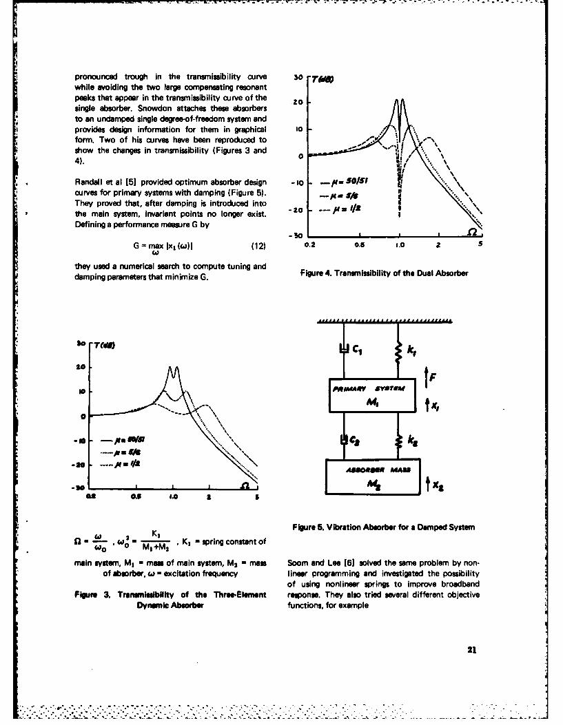
pronounced trough in the transmissibility curve 60 TA)while avoiding the two large compensating resonantpeaks that appear in the transmissibility curve of the 0osingle absorber. Snowdon attaches these absorbersto an undamped single degree-of-freedom system andprovides design information for them in graphical toform. Two of his curves have been reproduced toshow the changes in transmissibility (Figures 3 and o4).
Randall et al [5] provided optimum absorber design - 1O /. SO/$ fcurves for primary systems with damping (Figure 5). - /8They proved that, after damping is introduced intothe main system, invariant points no longer exist.Defining a performance measure G by
--30G = max Ix, (to)l (12) 0.2 0.5 1.0 2 $
'4W
they used a numerical search to compute tuning anddamping parameters that minimize G. Figure 4. Transmissibility of the Dual Absorber
30 [ CA, jkC
AWN -- , '" ..,
-JO~ t
I &L
W I K I-pigcnttof Figure 5. Vibration Absorber for a Damped Systemno Mn+M2
main system, MI - man of main system, M2 - mass Soom and Lee (6) solved the same problem by non-of absorber, wi - excitation frequency linear programming and investigated the possibility
of using nonlinear springs to improve broadbandFigure 3. TransmIssibility of the Three-Element response. They also tried several different objective
Dynimic Absorber functions, for example
21
:.~~.-..... . . ".,-' , . **.. - -. - . :-" . - .

G, Ix, (w) - 1 1)2 for c such that Ix, (w)I> 1 where z, is as defined in equation (1); the frequencyinterval of interest is [a,b]. They minimize G subject
G2 r x(wlx, (W) I ) to the constraints! (13)
Gs = Jx, () 12 max I - I < max (16)
G 4 = 0Ix , (W ) 12
Nonlinearities have also been treated by Roberson 'MIN<f fMAX (17)
[71 and Arnold [8]. Roberson considered the systemshown in Figure 6 in which the spring between the /MIN < t< MAX (18)
masses M, and M2 is nonlinear. Its load-deflection
curve is the sum of a linear and a cubic term. Because The notation is as in equation (1). They showed
the absorber is undamped in this case, its effective- that, for certain finite frequency intervals, designs
ness is limited to a small frequency range. Roberson's superior to Den Hartog's infinite frequency range
synthesis criterion is the maximization of this sup- optimum can be found.
pression band.
SYSTEMS WITH CONTUUOUS MEMBERS
K' Plunkett [11] proved the existence of invariantpoints for undamped continuous systems to which
,C Ja single discrete damper has been connected. He
." exploited this property to determine optimum
-.W damping for these systems. His approach is a general-ization of the methods of Den Hartog [1, 2] and
Lewis [31. He considers the vibration velocity at oneFigure 6. Vibration Absorber with Nonlinear Spring point of a linear system resulting from a sinusoidal
force at another point.
Arnold 81 studied the same system as Roberson but Let the force applied at a point 1 be F, and v, be
set c = 0. He provides frequency response curves of the velocity at the same point. Suppose a damperhset c syste prvide and sonse cupling with damping constant c is applied across points
the system for hardening and softening coupling with relative velocity v2 . Let the unknown vibrationsprings as well as for a softening spring designed velocity at the point of interest be v 3 . Plunkett shows
according to Roberson's optimum system-parameter that
specifications. In both cases (7, 81 the restoring force
in the nonlinear spring is taken as a function of spring
extension. - =jbl (19)F, 1+jb 3c
R(x) = c(x ± 2x 3 ) (14)
and notes that equation (19) has the same form asThe plus sign indicates a hardening spring charac- Den Hartog's equation (3). Thus when b/b s = 1,
teristic and the minus sign indicates a softening one. the ratio v3 /F1 is independent of c and has theinvariant points property described above in con-
Kwak et al [91 and Haug and Arora [10] used a junction with the conventional dynamic vibration
steepest descent algorithm to solve the classical absorber. The value of c that gives a zero slope of
absorber problem over a finite frequency range. Their the amplitude vs/F, I with respect to frequency
objective function is at the invariant value of Ivs/F, I is an optimum value
for c. Henney and Raney [121 applied a similar
G = <a J z1 () (15) technique to optimize damping for vibrating uniform
22
b ems and studied the sensitivity of maximum dis- h- . L .FplW nt response to deviation from optimum .
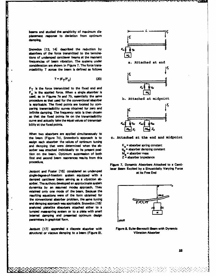
absorbers of the force transmitted to the termina-tions of undamped cantilever beams at the resonantfrequencies of beam vibration. The systems under a. Attached at endconsderaion ae shown in Figure 7. The force trens-mlosibllity T across the boom is defined as follows"r
T - IFT/Fol (20)
FT is the force tramitted to the fixed end andFo is the applied force. When a single absorber isused, as In Figures 7a and 7b, essentially the same b. Attached at midpointprocedure as that used for the conventional absorberis applicable. The fixed points are located by com- FTparing transmissbility curves obtained for zero andinfinite damping. The frequency ratio is then chosenso that the fixed points lie on the tranminlbilitycurve and actually take the equal values of transmisi- I
bility at the fixed pointsL
When two absorbers are applied simultaneously tothe beam (Figure 7c), Snowdon's approach is to c. Attached at the end and midpointassign each absorber the values of optimum tuningand damping that were determined when the ab- Ka - absorber spring constantsorber was attached individually to its present posi- ta - absorber damping constanttion on the beam. Optimum suppression of both Me - absorber massfirst and second beam resonances results from this Z - absorber impedanceprocedure.
Figure 7. Dynamic Absorbers Attached to a Canti-lover Beam Excited by a Sinusoidally Varying ForceJacquot and Foster (151 considered an undmrnpe athIs FeeEnid
singledeogree~of-fredom system equipped with a
damped cantilever boom serving as a vibration ab-sorber. The authors developed an approximate systemdynamics by en assumed modes approach. They A
retained only one mode of the beam. Becaus theresulting equations were of the form obtained forthe conventional absorber problem, the seine tuningaend damping approach was applicable. Snowdon (16)analyzed pletelike dmdem attached either to a h
lumped masepring system or to a piate with smallinternal damping and presented optimum designparams in graphical form.
Jacquot (171 appeinded a discr t absorber with Figure L Euler-Bernoulli Sern with Dynamicstructural or viscous damping to a beom (Figure 8). Vibration Absorber
28
-:": ... :- . .. . .
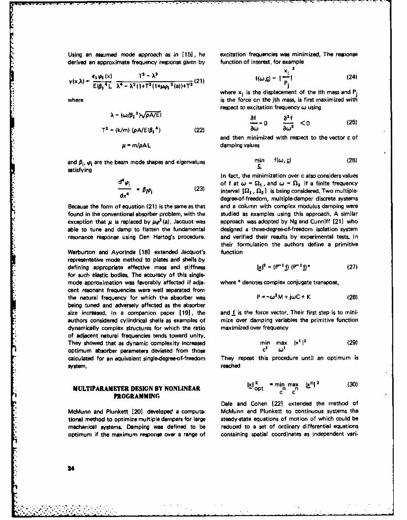
Using an assumed mode approach as in [151, he excitation frequencies was minimized. The responsederived an approximate frequency response given by function of interest, for example
xi
el1p, (x)T2-k2X2__ _~_(x)__" __-21) f(wg) = 1 - 1 (24)
y(x l) 14 L X2 A(1+T2 (l+ 2 (a))+T (21) where xi is the displacement of the ith mass and P.
where is the force on the jth mass, is first maximized withrespect to excitation frequency w using
X = (w / 1 ) Ip / EI af a2 f= 0 - <0 (25)
T2 = (k/m) (pA/EIP14 ) (22) a aC. 2
and then minimized with respect to the vector c ofp = m/pAL damping values
and Pi, si are the beam mode shapes and eigenvalues min f(w, c) (26)
satisfyingIn fact, the minimization over c also considers values
d4pi of f at c = I, and ci = 12 if a finite frequency- = i(23) interval [Ell, 12 ] is being considered. Two multiple-
dx4 degree-of-freedom, multiple-damper discrete systems
Because the form of equation (21) is the same as that and a column with complex modulus damping werefound in the conventional absorber problem, with the studied as examples using this approach. A similarexception that a is replaced by p 2 (a), Jacquot was approach was adopted by Ng and Cunniff [21] whoable to tune and damp to flatten the fundamental designed a three-degree-of-freedom isolation systemresonance response using Den Hartog's procedure, and verified their results by experimental tests. In
their formulation the authors define a primitiveWarburton and Ayorinde [18] extended Jacquot's functionrepresentative mode method to plates and shells bydefining appropriate effective mass and stiffness Ixl2= (r'I!) (P-) (27)for such elastic bodies. The accuracy of this single-mode approximation was favorably affected if adja- where * denotes complex conjugate transpose,cent resonant frequencies were well separated fromthe natural frequency for which the absorber was P = -w 2 M + jwC + K (28)being tuned and adversely affected as the absorbersize increased. In a companion paper [19], the and f is the force vector. Their first step is to mini-authors considered cylindrical shells as examples of mize over damping variables the primitive functiondynamically complex structures for which the ratio maximized over frequencyof adjacent natural frequencies tends toward unity.They showed that as dynamic complexity increased min max Ix' 12 (29)optimum absorber parameters deviated from those c' cot
calculated for an equivalent single-degree-of-freedom They repeat this procedure until an optimum issystem, reached
MULTIPARAMETER DESIGN BY NONLINEAR opt = maX jnl (30)
PROGRAMMING c cDale and Cohen [221 extended the method of
McMunn and Plunkett [201 developed a compute- McMunn and Plunkett to continuous systems thetional method to optimize multiple dampers for large steady-state equations of motion of which could bemechanical systems. Damping was defined to be reduced to a set of ordinary differential equationsoptimum if the maximum response over a range of containing spatial coordinates as independent vari-
24

-Aw r -'-YV Z'_7 _ A W" -7 7
" ables. Both dissipative and nondissipative design whereparameters were included. 2
2
Lunden [23] presented a nonlinear programming n E (34)
solution based on a se4uential unconstrained mini- If the end of the rod at x = 0 is subjected to a sinu-mization technique. The problem was to determine soidally varying force Fo , then the driving pointa continuous damping distribution that minimizes impedance Zo is given bythe maximum response of a vibrating beam over a FFospecified frequency interval. In a second paper [24] Zo= - (35) F=the author applied the same approach to vibrating (/at)x= 0 Jiw(x=o)frames. In these references, the maximum response F Snowdon [14] shows that the impedance Zo definedin the frequency interval studied is written as in equation (35) can be written as
F(11d, ns) = max f(i/d, ns, W) (31) 1- ReJO(a w~ Zo = Ap'E 1- RJ (36)
1 + ReJ-Pwhere ild denotes distributed structural damping and1 s denotes the structural damping constants for dis- ReJW describes the relative magnitude of and the
crete springs in the system. An exact displacement phase difference between incident and reflectedmethod is used with hysteretic damping introduced waves. The characteristic impedance Zch is definedby the loss factor r/d giving a complex bending as the impedance of an infinitely long rod in whichstiffness El(1 + j-/d). The 4 x 4 stiffness matrix for reflections do not occur. The value of Zch is ob-a beam element then takes the form tained from equation (36) by equating R to zero
E .F = + j _d)K x (32) Zch=A\/ (37)
where K is a 4 x 4 matrix of transcendental functions A matched condition will occur if a damper of damp-of frequency. ing constant Zch is attached to the rod at x = 0. This
attachment causes the ratio R of reflected to incidentKitis [25] utilizes structural reanalysis and modal wave to be zero so that no vibration response builduptechniques with nonlinear programming to make due to reflected waves is possible.tractable problems in which the systems under con-sideration contain a large number of degrees of This idea has been applied to shafts on supports [261.freedom. The repetitive computations of response Here the dynamic response is expressed in progressiverequired in the nonlinear programming portion of waveform-like electrical response waves in transmis-the optimal design are carried out using efficient sion line theory. Waveforms for a uniform shaft flex-reanalysis methods or condensed eigenproblem solu- ibly supported on two rotational and translationaltions; computation time in the structural analysis mass-spring-damper units at the ends and one suchphase of the design is thus reduced. unit in the interior are obtained. The terminating im-
pedance is made equal to the characteristic imped-ance of the shaft to obtain a matched condition.KAIPEDANCE MATCHING
The progressive wave solution to the wave equationfor continuous chain-like systems has been used to L -Iminimize vibratory response over a frequency range -Jby means of impedance matching. An illustration ofthe basic idea of this technique is the rod shown inFigure 9 [14]. Designate the displacement at anypoint x by and write the wave equation as E_ X A, E
+ n= 2= 0(3ax+2 (33 Figure 9. Rod under Longitudinal Vibration
25
LIMITING PERFORMANCE METHODS 2. Den Hartog, J.P,, Mechanical Vibration, McGrawHill (1947).
A limiting perform -e approach has been applied[27, 28] to the optimal design of vibratory systems 3. Lewis, F.M., "Extended Theory of the Viscousover a frequency range. In this approach, the design Vibration Damper," J. Appl. Mech., Trans.configurations are not fixed at the outset rather, ASME,22 p 377 (1955).those parts of the system to be designed are replacedby control forces. For a selected cost function and 4. Snowdon, J.C., "Dynamic Vibration Absorbers
-. design constraint the absolute optimal performance That Have Increased Effectiveness," J. Engrg.of the system can be computed by solving an optimi- Indus., Trans. ASME, p 940 (Aug 1974).zation problem in which the control forces are un-knowns. The solution is called the limiting perfor- 5. Randall, S.E., Haisted, D.M., and Taylor, D.L.,mance of the system. "Optimum Vibration Absorbers for Linear
" Damped Systems," ASME Paper 78-WA/DE-22
After the limiting performance characteristics have D d e Ar)Dbeen found, the designer can choose a prospective (1978).
configuration for the part of the system to be de-signed. He can apply parameter identification tech- 6. Soom, A. and Lee, M., "Optimal Design of
niques to find optimum design variable values so Linear and Nonlinear Vibration Absorbers for
that the designed system responds as closely as Damped Systems," ASME Paper 81-DET-83
possible to the limiting performance response. The (1981).limiting performance characteristics are found bylinear programming; parameter identification can be 7. Roberson, R.E., "Synthesis of Nonlinear Dy-accomplished by such curve fitting techniques as namic Vibration Absorbers," J. Franklin Inst.,least squares. This two-stage procedure has been 24, p 205 (1952).demonstrated for the optimal design of rotor suspen-sion systems (27]. 8. Arnold, F.R., "Steady State Behavior of Systems
Provided with Nonlinear Vibration Absorbrs,"BOOKS AND MONOGRAPHS J. Appl. Mech., Trans. ASME, , p 487 (1955).
The book by Haug and Arora [10] contains con- 9. Kwak, B.M., Arora, J.S., and Haug, E.J., "Orsiderable material applicable to frequency response mum Design of Damped Vibrati- Absortshaping; specialized aspects are not treated in detail, over a Finite Frequency Range." A4,- J., j_.Two other useful references are the monograph by p 540 (Apr 1975).Sevin and Pilkey [28] and the book by Snowdon[14]. Sevin and Pilkey present an introduction to the 10. Haug, E.J. and Arora, J.S., Applied Optimalsubject and a summary of the state of the art up to Design, John Wiley & Sons (1979).1971. Snowdon's book contains a wealth of informa-tion on vibration absorbers and reduction of beam 11. Plunkett, R., "The Calculation of Optimumvibrations. Concentrated Damping for Continuous Sys-
tems," J. Appl. Mach., Trans. ASME, 25, p 219ACKNOWLEDGMENT (1958).
This work was supported by the Office of Naval 12. Henney, A. and Raney, J.P., "The OptimizationResearch, Arlington, Virginia. of Damping of Four Configurations of a Vi-
brating Beam," J. Engrg. Indus., Trans. ASME,REFERENCES 85, p 259 (1963).
1. Ormondroyd, J. and Den Hartog, J.P., "Theory 13. Snowdon, J.C., "Vibration of Cantilever Beamsof the Dynamic Vibration Absorber," Trans. to Which Dynamic Absorbers Are Attached,"ASME, 50 (1928). J. Acoust. Soc. Amer., 39, p 378 (1966).
!26
14. Snowdon, J.C., Vibration and Shock in Damped 22. Dale, O.B. and Cohen, R., "MultiparameterMechanical Systems, John Wiley & Sons (1968). Optimization of Damped Linear Continuous
Systems," J. Engrg. Indus., Trans. ASME, p 115. Jacquot, R.G. and Foster, J.E., "Optimal Canti- (Feb 1972).
lever Dynamic Vibration Absorbers," J. Engrg.Indus., Trans. ASME, 99, p 138 (Feb 1977). 23. Lunden, R., "Optimum Distribution of Additive
Damping for Vibrating Beams," J. Sound Vib.,16. Snowdon, J.C., "Platelike Dynamic Vibration 66 (1), p 25 (1979).
Absorbers," J. Engrg. Indus., Trans. ASME, p 88(Feb 1975). 24. Lunden, R., "Optimum Distribution of Additive
Damping for Vibrating Frames," J. Sound Vib.,17. Jacquot, R.G., "Optimal Dynamic Vibration 72 (3), p 391 (1980).
Absorbers for General Beam Sytems," J. SoundVib., 60 (4), p 535 (1978). 25. Kitis, L., Optimal Passive Frequency Response
Control of Large Mechanical Systems Ph.D.18. Warburton, G.B. and Ayorinde, E.O., "Optimum Thesis, University of Virginia (May 1982).
Absorber Parameters for Simple Systems," Intl.J. Earthquake Engrg. Struc. Dynam., 8, p 197 26. Friedericy, J.A., Liu, Y.N., and Eppink, R.T.,(1980). "Solutions for the Optimization of Support
Conditions of Hypercritical Shafts on Three19. Ayorinde, E.O. and Warburton, G.B., "Minimiz- Flexible Supports," Develop. Theoret. Appl.
ing Structural Vibrations with Absorbers," Intl. Mech., 3 pp 563-593 (1966).J. Earthquake Engrg. Struc. Dynam.,8, p 219(1980). 27. Pilkey, W.D., Wang, B.P., and Vannoy, D., "Effi-
cient Optimal Design of Suspension Systems for20. McMunn, J.C. and Plunkett, R., "Multiparameter Rotating Shafts," J. Engrg. Indus., Trans. ASME,
Optimum in Linear Dynamic Systems," ASME 98 (3) (Aug 1976).Paper 69-VIBR-42 (1969).
28. Sevin, E. and Pilkey, W.D., Optimum Shock21. Ng, C. and Cunniff, P.F., "Optimization of and Vibration Isolation Monograph No. 6,
Mechanical Vibration Isolation Systems with The Shock and Vibration Information Center,Multi-degrees of Freedom," J. Sound Vib., 36 Naval Research Lab., U.S. Dept. Defense, Wash-(1), p 105 (1974). ington, D.C. (1971).
27
*r . - ... .. ,
BOOK REVIEWS
FREE VIBRATION ANALYSIS and b/a as listed above. When free edges are involved,OF RECTANGULAR PLATES Poisson's ratio is set at 0.333.
D.J. Gorman The last chapter is devoted to a series of problems
Elsevier-North Holland Pub. Co., New York, NY of rectangular plates either with added point masses1982; 324 pages; $60.00 or supports or with line supports. Again the super-
position procedure is used; results for frequenciesare given. Results for frequencies given throughout
This work is a summarization and generalization of the book are comprehensive; however, considerablya number of previously published papers by Pro- less information is supplied about the correspondingfessor Gorman dealing with the free vibrations of mode shapes.rectangular plates. It presents the most comprehen-sive set of published analytical results to date for The reviewer recommends the book to individualsrectangular plates governed by classical plate theory; interested in applying the superposition method tothat is, the plates are homogeneous, isotropic, and the analysis of eigenvalue problems for rectangularthin and undergo vibrations of amplitude less than regions and those who desire extensive, accuratethickness and free of in-plane initial stresses. No numerical results for the free vibration of rectangular
comparisons are made with the voluminous numerical plates governed by classical theory.results found elsewhere in the literature; the resultsare based on the author's own accurate calculations. A. Leissa
Department of Engineering MechanicsChapter 2 presents comprehensive eigenfrequencies Ohio State Universityfor six cases of rectangular plates having two opposite Columbus, OHsides simply supported and the others simply sup-ported, clamped, or free. These problems haveexact solutions in the sense that the eigenfrequenciesare obtained ;:om frequency determinants of finite VIBRATIONS OF SHELLS AND PLATESsize; in this case the orders are no larger than four,and the well known Voigt-Levy solution of the equa- W. Soedeltion of motion is used. For each of the six cases, 64 Marcel Dekker, Inc., New York, NYfrequencies are presented for a/b and b/a = 1, 1.25, 1981; 366 pages; $45.001.5, 2, 2.5, and 3; a and b are the plate dimensions.For plates having free edges (three cases) results aregiven for two values of Poisson's ratio (0.333 and This book aims "to give engineering graduate students0.5). and practicing engineers an introduction to the
vibration behavior of shells and plates." In theChapters 3 through 7 deal with the remaining 15 opinion of the reviewer the author has succeededcases of plates with combinations of clamped, simply very well. He points out that shell vibrations receivesupported, and free edges. The method of superim- little or no attention in typical vibrations textbooks.posing infinite series of Voigt-Levy solutions previ- The primary emphasis of the book is on shells; platesously developed by the author and others is utilized. (and even membranes, straight beams, and rings) areConvergence studies were made to establish the used mainly to provide simple examples when shellsaccuracy of the frequences to four significant figures. would be unduly complicated. Professor Soedel men-Numerical results for frequencies are typically given tions in his Preface that the book evolved from a setfor the first ten modes in each case for values of a/b of lecture notes developed over a ten-year period.
28
....................
1
The chapters are as follows: Chapters 6 and 7 contain approaches that are usefulwhen exact solutions become untractable. Simpli-
1. Historical Development of Vibration Analysis of fied shell equations include those of membrane,Continuous Structural Elements inextensional, and shallow shell theory; they are
2. Deep Shell Equations applied to the free vibrations of several shell con-3. Equations of Motion for Commonly Occurring figurations. Approximate procedures discussed in
* Geometries Chapter 7 include the interconnected direct varia-4. Non-Shell-Type Structures tional, Galerkin, and Rayleigh-Ritz methods (with5. Natural Frequencies and Modes beam functions); finite differences; finite elements;6. Simplified Shell Equations and the Southwell and Dunkerley theorems.7. Approximate Solution Techniques8. Forced Vibrations of Shells by Modal Expansion Chapters 8 through 10 deal with forced vibrations.9, The Dynamic Influence (Green's) Function The classical approach for viscously damped systems
10. Moment Loading and an expansion of the displacements and forcing11. Vibrations of Shells and Membranes under the functions in terms of the free vibration eigenfunc-
Influence of Initial Stresses tions are described. Point and line loads are also dis-12. Shell Equations with Shear Deformation and cussed. Dynamic influence functions are demon-
Rotatory Inertia strated by traveling point loads on shells.13. Combinations of Structures14. Hysteresis Damping The complicating effects of initial stress, shear defor-15. Shells Made of Composite Material mation, and rotary inertia are discussed in Chapters
11 and 12. The rotating saw blade is used as anChapter 1 presents some interesting perspectives of example. Beams, plates, and shells are also described.24 historical figures from Galileo to Love; most of The last three chapters contain introductions tothe references were written before 1850. Chapter 2 special topics of practical importance.is a derivation of the equations of Love's theory incurvilinear coordinates. In Chapter 3 these equations The book is interestingly written and easy to follow.are specialized to shells of revolution and to conical, The reviewer recommends it particularly to thecylindrical, and spherical shells. In Chapter 4 the individual who has previously studied vibrations ofequations are reduced further to straight and curved discrete systems, rods, beams, and plates and wantsbeams and plates. Some classical exact, free vibration a beginning understanding of shell vibrations.solutions for straight beams, circular rings, circularplates, simply supported rectangular plates, and A. Leissacircular cylindrical shells are presented in Chapter 5; Department of Engineering Mechanicsother sections deal with the orthogonality, super- Ohio State Universityposition, and damping distortions of modes. Columbus, OH
29
. . •................................°............ . ... -. ~ .........
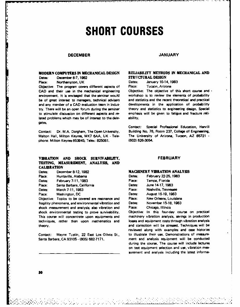
SHORT COURSES
DECEMBER JANUARY
MODERN COMPUTERS IN MECHANICAL DESIGN RELIABILITY METHODS IN MECHANICAL ANDDates: December 6-7, 1982 STRUCTURAL DESIGNPlace: Northampton, UK Dates: January 10-14, 1983Objective: The program covers different aspects of Place: Tucson, ArizonaCAD and their use in the mechanical engineering Objective: The objective of this short course andenvironment. It is envisaged that the seminar would workshop is to review the elements of probabilitybe of great interest to managers, technical advisers and statistics and the recent theoretical and practicaland any member of a CAD evaluation team in indus- developments in the application of probabilitytry. There will be an open forum during the seminar theory and statistics to engineering design. Specialto stimulate discussion on different aspects and re- emphasis will be given to fatigue and fracture reli-lated problems which may be of interest to the dle- ability.gates.
Contact: Special Professional Education, HarvillContact: Dr. M.A. Dorgham, The Open University, Building No. 76, Room 237, College of Engineering,Walton Hall, Milton Keynes, MK7 6AA, UK - Tale- The University of Arizona, Tucson, AZ 85721 -
phone: Milton Keynes 653945; Telex: 825061. (602) 626-3054.
VBRATION AND SHOCK SURVIVABILITY, FEBRUARYTESTING, MEASUREMENT, ANALYSIS, ANDCALIBRATIONDates: December 8-12, 1982 MACHINERY VIBRATION ANALYSISPlace: Huntsville, Alabama Dates: February 22-25, 1983Dates: February 7-11, 1983 Place: Tampa, FloridaPlace: Santa Barbara, California Dates: June 14-17, 1983Dates: March 7-11, 1983 Place: Nashville, TennesseePlace: Washington, DC Dates: August 16-19, 1983Objective: Topics to be covered are resonance and Place: New Orleans, Louisianafragility phenomena, and environmental vibration and Dates: November 15-18, 1983shock measurement and analysis; also vibration and Place: Chicago, Illinoisshock environmental testing to prove survivability. Objective: In this four-day course on practicalThis course will concentrate upon equipments and machinery vibration analysis, savings in productiontechniques, rather than upon mathematics and losses and equipment costs through vibration analysistheory, and correction will be stressed. Techniques will be
reviewed along with examples and case historiesContact: Wayne Tustin, 22 East Los Olivos St., to illustrate their use. Demonstrations of measure-Santa Barbara, CA 93105- (805) 682-7171. ment and analysis equipment will be conducted
during the course. The course will include lectureson test equipment selection and use, vibration mea-surement and analysis including the latest informs-
so___-_______,_.. . .. .___.___•___,_._____._. . . . . . .
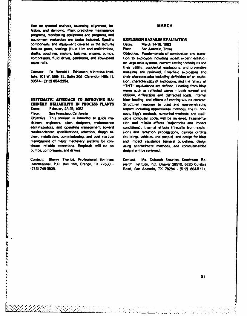
* tion on spectral analysis, balancing, alignment, iso- MARCHlation, and dumping. Plant predictive maintenanceprograms, monitoring equipment and programs, andequipment evaluation are topics included. Specific EXPLOSION HAZARDS EVALUATIONcomponents and equipment covered in the lectures Dates: March 14-18,1983include gears, bearings (fluid film and antifriction), Place: Son Antonio, Texas
, shafts, couplings, motors, turbines, engines, pumps, Objective: Fundamentals of combustion and transi-- compressors, fluid drives, gearboxes, and slow-speed tion to explosion including recent experimentation
paper rolls, on large-scale sstems, current testing techniques andtheir utility, accidental explosions, and preventive
Contact: Dr. Ronald L. Eshleman, Vibration Insti- measures re reviewed. Free-field explosions andtute, 101 W. 56th St., Suite 206, Clarendon Hills, IL their characteristics including definition of an explo-00614 - (312) 654-2254. sion, characteristics of explosions, and the fallacy of
"TNT'" equivalence awe defined. Loading from blastwaves such as reflected waves - both normal andoblique, diffraction and diffracted loads, internal
SYSTEMATIC APFROACI TO IMPROVING MA. blast loading, and effects of venting will be covered.CHINERY RELIABILIY IN PROCESS PLANTS Structural response to blast and non-penetratingDates: February 23-25, 1963 impact including approximate methods, the P-i con-Place: San Francisco, California cept, Bigg's methods, numerical methods, and appli-Objective: This seminar is intended to guide me- cable computer codes will be reviewed. Fragmenta-chinery engineers, plant designers, maintenance tion and missile effects (trajectories and impactadministrators, and operating management toward conditions), thermal effects (fireballs from explo-results-oriented specifications, selection, design re- sions and radiation propagation), damage criteriaview, installation, commissioning, and post start-up (buildings, vehicles, and people), and design for blastmanagement of major machinery systems for con- and impact resistance (general guidelines, designtinued reliable operations, Emphasis will be on using approximate methods, and computer-aidedpumps, compressors, and drivers, design) will be reviewed.
Contact: Sherry Theriot, Professional Seminars Contact: Ms. Deborah Stowitts, Southwest Re-International, P.O. Box 156, Orange, TX 77630 - search Institute, P.O. Drawer 28510. 6220 Culebra(713) 746-3506. Road, San Antonio, TX 78284 - (512) 6845111.
81
.'., . .-.. -'.,'..' . " '.." .. '- ." " ".- ?" " ' .. ', ".. . . , . . "
NE S RIFS and Futur Shook andNEWS BRE S Vllirtion actlltle and event
MECHANICAL FAILURES PREVENTION GROUP SYMPOSIUMTeebriuul Advames md l keir apect om Delsedom, Digmeb and Proposi
The 36th Mechanical Failures Prevention Group (MFPG) Symposium will be heldDecember 6-10, 1982 at the La Posada Hotel, 4949 East Lincoln Drive, Scottsdale,
"* Arizona 85253- (800) 528-7869. The meeting is sponsored by National Bureau ofStandards, Office of Naval Research, Naval Air Systems Command, with participa-tion by the IEEE Reliability Society.
The Symposium will consist of Technical Sessions addressing: Sensors and Instru-mentation, New Technologies and Techniques, Applications of Date Processing,Machinery Health Monitoring, Prognosis of Failure, and "Living Papers." The"Living Papers" will consist of visits to local industry and government facilities bythose who register in advance. Proceedings will be distributed at the time of regis-tration.
For further information contact: Mr. T.R. Shives, Executive Secretary, MFPG,Materials Building, Room A-1 13, National Bureau of Standards, Washington, DC20234.
INTERNATIONAL CONFERENCEON MODERN VE ICLE DESIGN ANALYSIS
June 21-24, 196Lesde, UK
The International Association for Vehicle Design will sponsor a symposium onModern Vehicle Design Analysis to be held June 21-24, 1983 in London, England.Contributed papers are invited in all areas of vehicle design analysis and especiallyfor applications of structural optimization, graphics as a computational and designtool, vehicle noise and vibration control techniques, nonlinear calculations includ-ing crashworthiness studies, and new structural materials for weight and costsavings.
For further information contact: Drs. Mounir M. Kamal and Joseph A. Wolf, Jr.,symposium organizers, Engineering Mechanics Department, General Motors Re-search Laboratories, Warren, MI 48090 - (313) 575-2929; or Dr. M. Dorgham,International Association for Vehicle Design, The Open University, Milton Keynes,MK7 6AA, England.
32
44. .

INFORMATION RESOURCES
SOIL MECHANICS INFORMATION AND ANALYSIS CENTER (SMIAC)
INTRODUCTION ORGANIZATION
The Soil Mechanics Information and Analysis Center The SMIAC is staffed by a director and one other(SMIAC) is located at the U.S. Army Engineer Water- geotechnical engineer. Technical assistance in devel-ways Experiment Station (WES) in Vicksburg, Missis- oping answers to specific questions is provided bysippi. It is one of four Department of Defense (DOD) the engineers and scientists of the Soil Mechanics,information analysis centers at WES and was estab- Engineering Geology and Rock Mechanics, and thelished in 1966. The Center provides users with infor- Earthquake Engineering and Geophysics Divisionsmation in soil mechanics, engineering geology, rock of the WES Geotechnical Laboratory. Questions onmechanics, engineering seismology, geophysics, earth- the response of soils to blast and shock loading arequake engineering, and soil dynamics. It primarily referred to the Geomechanics Division of the WESserves technical information needs of the Department Structures Laboratory.of the Army, Research and Development community,and the Corps of Engineers' Civil Works and Military Funding to operate the Center is provided by theactivities. Because of the concentration of both civil U.S. Army Materiel and Readiness Command (DAR-and military research related to its subject areas at COM) and the Civil Works Directorate of the Office,WES, much of the assistance rendered by the Center Chief of Engineers.is provided to WES researchers. A significant numberof requests for geotechnical information from otherDOD agencies, contractors, and the scientific com- RESOURCES AND OPERATIONmunity are also handled each year.
The principal resource of the SMIAC is people.Nearly 100 specialists in various aspects of the sub-
MISSION AND APPROACH ject matter covered by this SMIAC are available atWES as resource persons. Their ready knowledge ofthe field of research in which they work makes
The mission of the SMIAC is to collect, analyze, possible quick, accurate, and specific answers toevaluate, condense, and disseminate technical infor- many of the queries received by the Center.mation in its subject areas to a broad group of users.The current volume of material being published in The SMIAC draws support from the WES Technicalits subject area is enormous. A potential user of the Information Center whose library contains aboutCenter could undertake his own literature search 80,000 items relating to the field covered by theand review in any good technical library and would Center. These items include books, technical journals,eventually find the specific information being sought. reports, periodicals, reprints, and microfilm. In addi-Most individuals do not have time to do this; they tion to the card catalog, relevant indexes availableneed a specific answer to a specific question. The in the library include Engineering Index, AppliedSMIAC tries to provide this answer by referring the Science and Technology Index, British Technologyrequestor to a specific reference or to an expert who Index, Monthly Catalog of U.S. Government Publi-is knowledgeable about the problem. The Center also cations, and Government Reports Index. In addi-performs literature searches in specific subject areas tion, the library has the following other catalogs fromwhen asked. libraries or information centers in either card or book
................... _,..,. .
form: U.S. Geological Survey Library, Engineering necessary to produce the desired result. In the case ofSocieties Library, John Crerar Library (Chicago), more complex studies, this takes the form of a letterand the Library of Congres. A remote on-line termi- report to the user providing the technical data ornal links SMIAC through the WES library with the information requested. Requests for loan of publica-Defense Research and Development Test and Evalu- tions are referred to the WES library. Requests foration On-Line System's Technical Report and Work retention copies of WES reports are usually referredUnit Data Banks. The SMIAC also uses the Lockheed to Defense Technical Information Center (DTIC) or
* Information System DIALOG to access a number of National Technical Information Service (NTIS).data bases of geotechnical interest. Geodex, Geotech- However, on occasion, the SMIAC is able to supply anica/ Abstiyct, and Rock Mechanics Abstracts are retention copy of a recent WES report.hands-on data bases which the Center uses regularlyin its work. Cuffent awwnem program. Internal to WES, the
SMIAC provides a current awareness service to WESThe SMIAC also serves as the repository for a portion researchers. This is accomplished by scanning DTICof the personal papers of the late Dr. Arthur Casa- current publication lists and selected journals andgrande, a long-time consultant to the Corps of Engi- providing individuals with abstracts which are be-neers and an internationally recognized leader in soil lieved relevant to their current activities.mechanics.
Special studiem The Center is currently preparing anThe day-to-day operation of the Center involves re- English, French, German, and Russian languagesponses to telephone or written requests for informa- Soil Mechanics Glossary of over 8500 terms. Publi-tion. These responses take three forms: (a) oral or cation is expected in 1983. In addition, SMIAC haswritten advice from a technical expert or the WES added several thousand entries of abstracts of soilstaff, (b) specific reference to a particular technical mechanics literature from non-DOD sources intodocument plus arrangement for loan of that docu- the DTIC technical report data bank for ready access.ment by the WES library, or (c) a literature search The Center also published the "Microthesaurus ofwhich results in a bibliography and set of abstracts Soil Mechanics Terms" in 1974.furnished to the requestor.
POINTS OF CONTACT FOR SERVICESSERVICES AND PUBLICATIONS
The SMIAC address is as follows:As indicated above, SMIAC serves its user communitythrough personal technical advisory services carried Commander and Directorout in close cooperation with the staffs of the Geo- U.S. Army Engineer Waterways Experiment Stationtechnical Laboratory and the WES Technical Infor- Attention: SMIACmation Center. Most requests for assistance take less P.O. Box 631than one day for response and no charge is made for Vicksburg, Mississippi 39180these services. Requests for service involving substan-tial efforts are handled on a cost-reimbursable basis. The telephone points of contact are:
Technical inquiries or requests for publications, Dr. Paul F. HadalaQuick response is provided through the personal Acting Director, SMIACgeotechnical expertise of the staff, referral to other (601) 634-3475WES experts, or the use of the various data bases de-scribed earlier. The staff conducts literature searches, Mr. Leslie Deveyreviews documents, and performs analyses where (601) 634-3541
34
'"............

ABSTRACTS FROMTHE CURRENT LITERATURE
Copies of articles abstracted in the DIGEST are not available from the SVIC or the Vibration Institute (exceptthose generated by either organization). Inquiries should be directed to library resources. Government reports canbe obtained from the National Technical Information Service, Springfield, VA 22151, by citing the AD-, PB-, orN- number. Doctoral dissertations are available from University Microfilms (DA), 313 N. Fir St., Ann Arbor, MI;U.S. Patents from the Commissioner of Patents, Washington, DC 20231. Addresses following the authors' namesin the citation refer only to the first author. The list of periodicals scanned by this journal is printed in issues1, 6, and 12.
ABSTRACT CONTENTS
MECHANICAL SYSTEMS ... 36 Blades...............52 MECHANICAL PROPERTIES. .69Bearings ............. 55:' ~~Rotating Machines ....... 36 Gas.6 Dmig6
ottnMchnsGears ................ 56 Damping ............. 69Reciprocating Machines ... 38 Fasteners ............. 56 Fatigue .............. 71Materials Handling Linkages ............. 57 Elasticity and Plasticity .73
Equipment..............Seals ................ 57
EXPERIMENTATION ...... 73*: STRUCTURAL SYSTEMS .... 38
STRUCTURAL COMPONENTS. 57Bridges .............. 38 Measurement and Analysis .73Buildings ............. 39 Cables ............... 57 Dynamic Tests ......... 75Towers .............. 41 Beams ............... 58 Diagnostics ............ 75Foundations ........... 41 Columns ............. 60 Balancing ............. 76Underground Structures... 42 Frames and Arches ...... 60 Monitoring ............ 76Construction Equipment... 42 Panels ............... 61Power Plants ........... 42 Plates ............... 61Off-shore Structures ..... 43 Shells ............... 62 ANALYSIS AND DESIGN .... 76
Pipes and Tubes ........ 63
VEHICLE SYSTEMS ........ Ducts ............... 63 Analogs and AnalogBuilding Components..63 Computation ....... 76
Ground Vehicles ........ 44 Analytical Methods ...... 76
Ships. ............... 45 Modeling Techniques ..... 80Numerical Methods ...... 80
Aircraft .............. 45 ELECTRIC COMPONENTS ... 64 Parmer Ietification.. 80Missiles and Spacecraft .... 48 Parameter Identification. ..80
Optimization Techniques 81
Controls (Switches, Design Techniques ....... 81
BIOLOGICAL SYSTEMS.....48 Circuit Breakers) . 64 Computer Programs ...... 81
Human .............. 48
DYNAMIC ENVIRONMENT...64 GENERAL TOPICS ......... 82
MECHANICAL COMPONENTS. 49 Acoustic Excitation ...... 64 Conference Proceedings ... 82Absorbers and Isolators ... 49 Shock Excitation ........ 67 Tutorials and Reviews .... 83Tires and Wheels ........ 52 Vibration Excitation ..... 69 Bibliographies .......... 83
35
ri .'; .,...... .-.... , ,.. ,... ... . -.. '.. ,, . . . .- _,- ......... . . . . . . . . . ... . .. . ..
-% ,m •
• " . .. .O ° . , , •. - ." . . . " . " . - , . • . , - . , , . o , - . - , , . . - , . o• .
,' , ". ' :. , . . . . .. : . _ .. . . . .. .. -. ....". " . ,. . . :. ' / ; o . . . . . . . _ . . . , . ,. .. , -
ME H NIA YS E Soff to oscillte. For design of dclyold pumpdrivee,
rmnetsamd for to protect gears bearings and shafts. Seriousp oblmsa due to lack of wowe we encountere wheno engineoutput is increaed.
(loROTATING MACHINES 82-2297(Asm No.. 2365.2372,2400.2438.2458) On the Seaiby of a Rotating Flaie Shaft Sup-
Posted by Jaukud 11uuimgY. Tsuda, J. Inoue, H. Tamura, and A. Sueoka
82-2285 Ohita Univ., 700 Dannoharu, Ohita-shi, Japan, Bull.On te Sabab ofRottiug Axdy oade, Hme- JSME, 25 (203). pp 85.661 (May 1982) 7 figs.
pees Shafta 7 refitJ. WauerInst. f. Technische Mochanik, Univ. Karlsruhe, Kaiser- Key Words: Shafts, Flexible shafts. Bearings, Journal bear-strasse 12, D-7500 Karlsruhe-1, Germany, Intl. J. Inge. Oil whip phenomenaSolids Struc., 18 (6), pp 459-466 (1982) 4 figs, 10refs5 The theoretical stability charctristics of a rotating elastic
shaft are Investigated. For a symmetrical rotating shaftmodal, In which the shaft with a rotor at Its midpoint Is
Key Words: Stability, Shafts, Deems. Rotating structures, supported by journal bearings, the limit frequency at whichTimosheonko theory, Continuous paramneter 00eho ~ whirl of conical mode starts (for both e~ati and rigid
shafts) can be analytically obtained in addition to the criticalUsin a otaingTimohenobem mbleced o aialpm- conditions which we absolutely stable against that mode of
sm ioad with internal and external damping a eea oil whip. A stability chart for the trenslational mode baedcirculatory vibraion system with distributed parameters is on infinitely short bearing approximations and Gumbel'sformulated in which stability behavior is discussed in detail. boundary condition is also presented&The effect of gyroscopic stabilization end its influence onthe different damping mechanisms is studied. By means ofmodern operator methods the well-known theorems ofThomson and Tait are generalized for one-dimensional.continuous rotor systems. M2=12
Cloed Fes Steady-State Solution for Ike Umbael-anoe Realpoase of a Rigid Rotor im Squeeze Flu,Dmnaper
82-2286 D. L. Taylor and B. R. K. Ku mar* Aceleatin o Tosionl C abhft UWBOIMCornell Univ., Ithaca, NY, ASME Paper No. 82-GT-a Diesell Engine with a Tuned Vibration Damper
(Dseuhwigun~eeeleuspngvon urbiwuien Key Words: Rotors, Rigid rotors, Unbalanced mass response.- - hei~ Dieelhnotossu mnit federgakoappullte. Drsehwwi Suee imdapr
guagediisupfern)F. Mart inek This paper considers the steady-state response due to unbal-MTZ Motortoch. Z., 41, (6), pp 269-270 (June 1982) anceat a planar rigid rotor carried in a short squemz film
ref s damper with linear centering spring. The damper fluid forefigs, are determined from the short bearing, cavitated solution of
(In Grman)Reynolds' equation.
Key Words: Shafts, Crankshafts, Torbional vibration, Dieselengines, Dynamic vibration absorbers (equipment)
8&-2289Vibratory stress from a crankshaft can be controlled by a InlecofUd dyAryaai onHglestuned torsional vibration damper. Vibrations in auxiliary Ifuneo ntayArdnnc nHueedrives are also reduced. Vibratory acceleration of a crank- Rotor Ground Resonaneshaft-mounted gear will force a rigidly coupled power take- W. Johnson
36
NASA Ames Res. Ctr., Moffett Field, CA, J. Aircraft, and separating it from the casing mode. Also Included ar19 (8), pp 668-673 (Aug 1982) 12 figs, 2 tables, effects of exhaust system weight on engine vibration and
%16 refs cabin noise levels.
Key Words: Rotors, Hingete"s rotors, Helicopters, Rotors
Calculations of the model frequency and dumping for a 82-292hingeles rotor on a glaaballed support in hover are compaed 8with measured results for two configurations Idiffering in Control of Self-Excited Flow Oacllations in Vaelless
bade flap stlffnesel. Good correlation is obtained when an Diffuser of Centrifugal Compremon Systemsinflow dynamics model is used to account for the influence A.N. Abdelhamidof the unsteady aerodynamics. The effect of the unsteady Carleton Univ., Ottawa, Canada, ASME Paper No.aerodynamics is significant for this rotor system. The inflow 82-GT-188dynamics model introduces additional states corresponding
to perturbations of the wake-induced velocity at the rotordisk. The calculations confirm the experimental observation Key Words: Cor.,resors, Centrifugal compressors, Fluid-that the Inflow mode introduced by these additional states induced excitationis measurable for one configuration but not for the other.
Experiments were conducted to evaluate the effectiveness ofaxisymmatric diffuser exit throttle in delaying the occurrence
of self-excited flow oscillation In vaneless diffusers. Sharpedge rings were installed at diffuser exit in order to changethe exit flow area. Tests were carried out with the rings
82290 attached to one or both of the diffuser wells. Steady and
Nowlbear Beering Effects on Rotor Dynamic Analy- unsteady flow measurements were used to determine the• ;, flow field In the diffuser at the onset of the flow oscillations.
R. Colsher, I. Anwar, and V. ObeidThe Franklin Inst. Res. Lab., Philadelphia, PA, ASMEPaper No. 82-GT-291
82-2293Key Words: Rotors, Fluid-film bearings, Transient response Criticl Speed in Centrifugal Pumps
Nonlinear effects due to fluid film bearings become signifi- S. Gopelakrishnan, R. Fehlau, and J. Lorett
cant when vibratory amrplitudes are large. To include these Borg-Warner Corp., Commerce, CA, ASME Papereffects in rotor dynamic analysis requires conducting time- No. 82-GT-277transient response analysis, where the fluid film forces are
estimated at each time step. This paper describes an approach Key Words: Pumps, Centrifugal pumps, Critical speedswhere a unique treatment of bearing forces resuits in anefficient computational scheme for performing time transient Simplified equations are derived for the calculations of fluidanalysis, gap. The results are verified by measurements on a test pump.
Sample calculations for a typical multistage boiler feed pumpare included as illustration.
82,2291Solution to a Bistable Vibration Problem Using aPlain, Uncetrdined Squeez Film Damper Bearing 82-2294J.A. Palladino and T.W. Gray Understand Criticd Speed of Pumps to Help PreditGeneral Electric Co., Lynn, MA, ASME Paper No. S. Giop liaAaanility82-GT-281 S. Gopalakrishnan, R. Fehlau, and J. Lorett
Byron Jackson Pump Div., Borg-Warner Corp., Power,
Key Words: Rotors, Turbines, Vibration control, Critical 1_a (1), pp 37-40 (Jan 1982) 10 figs, 5 refs
speeds, Bearings, Squeeze film dampersKey Words: Pumps, Critical speeds
This pop demonstrates that the use of a plain, uncentral-lried, squeOre film dumper to support the turbine rotor solves The influence of fluid gap, either at sealig rings or throttleall vibration problems by reducing the turbine critical speed bushings, can outweigh testic stiffness and greatly affect
37
L " . . . P 1
service instability of the pump. Simplified equations gi H. Flaigaid in poearing specifications. Mannesmann-Demag Fordertechnik, Wetter, Ruhr,
VDI Z., 124 (9), pp 341-344 (1982) 10 figs, 4 refs(In German)
"W -, Key Words: Cranes (hoists), Vibration dampingCakeulatiom of Wide-Baud Compomeata in the SoundPower Spectsun of Axi&lFw Fans (Vortex Noise) A new type of suspension for a rane cabin reduces the
vibration of the cab. The suspension can be used with anyeeadecab, regardless of weight and is suitable for any reorganiza-
Sekdilluagellektrun von Axilventlatoren (Wir- tion of crane installation.m)
S. Gruhl, K. Biehn, J. Plundrich, and P. KdltzschZentralinstitut f. Arbeitsschutz Dresden, Germany,Maschinenbautechnic, J1 (6), pp 269-272 (1982)4 figs, 7 refs 82-2298(In German) About the New Method to Regulate the Eccentric
Force of Mechanical VibratorsKey Words: Fans, Sound pressure levels, Vortex noise R. Bansevicius and A. Rovetta
Kaunas Polytechnical Inst., Kaunas, Lithuania, USSR,Using acoustic models of cascades, equations for the calcu- Meccanica, 4 (16), pp 181-191 (Dec 1981) 20 figs,lation of broadband sound power of axial-flow fans (vortex ---
noise) are derived. The random time-variable blade forces, 6 refscaused by turbulent flow, are taken as the acoustic excite-tion forces. From this dat sound power levels are deduced Key Words: Vibrators (machine), Vibration controland the sound power level of fens is approximated.
7 This paper presents a new method for continuous regulationof a vibratory machine oscillation amplitude, by acting onlyon the electronic equipment, which can be placed at a
RECIPROCATING MACHINES distance from the machine. The repuletion Is obtained bythe starting transient, with variation of the angular positions
222 of two unbalanced masses. Experimental tests on the analysisof the dynamics and stability of the motion of the rotating
Revilew of Diesel Ei e Noe unbalanced masses are reported. The influence of the me-M.J.J. Slabber chanical configuration of the system is examined.Atlantis Diesel Engines (Pty) Ltd., Cape Town, SouthAfrica, Presented at Intl. Symp. on TransportationNoise, CSIR Conf. Ctr., Pretoria, Oct 21-23, 1981,23 ppPB82-206087 STRUCTURAL SYSTEMSKey Words: Diesel engines, Engine noise, Reviews
The mechanism of noise generation from diesel engines and BRIDGESthe associated components and structures is presented.Methods to establish the main sources of noise and theeffectiveness of structural redesign together with the influ-ence of encapsulation we reviewed. 82-2299
Natural Oelltiom of Suspension BridgesF. Van der Woude
MATERIALS HANDLING EQUIPMENT Univ. of Tasmania, Hobart, Australia, ASCE J. Struc.Div., 108 (ST8), pp 1815-1829 (Aug 1982) 3 figs,2 tables, 9 refs
82-2297Crane Cab Vibraton Damping (Schwiagungadi4 p Key Words: Bridges, Suspension bridges, Natural frequencies,ftng far Krankabinen) Mode shapes
38
1"' ""' - -•"e
Natural modes and frequencies of a simple span suspension 82-2302bridge with straight backstays are investigated theoretically Effects of Traffi-Induced Vibrations on Bridge-Deckand experimentally. Fourier series representations of cable Repairsdisplacements are used in conjunction with the Lagrange Transportation Res. Board, Washington, DC, Rept.method to represent the system with a small number ofdegrees-of-freedom. Bridge system matrices are derived which No. TRB/NCHRP/SYN-86, ISBN-0-309-03304-7, 50take into account cable, gravity, bending, and torsional pp (Dec 1981)stiffnesses. Natural modes and frequencies are obtained PB82-198490as the elgensolutions of small order system matrices. Anumerical example is given from which approximate fre-quency formulas are derived. Experimental results in theform of frequency response curves are presented for a labo- This synthesis will be of special interest to engineers con-ratory model. cerned with placement of concrete for construction or
repair of bridge decks. Recommendations are provided forrestoring, patching, and widening bridge decks in the pres-ence of traffic. This report conclud. that traffic can bemaintained on the bridge while concrete is placed in deckrepairs, overlays, widenings, or replacements.
82-2300Comparison Between Theory and Experiment in theFlutter and Buffeting of Long-Span SuspensionBridges 82-2303H.-S.-W. Soo Seismic Design Guidelines for Highway BridgesPh.D. Thesis, Princeton Univ., 318 pp (1982) R.L. Mayes and R.L. SharpeDA8213546 Applied Technology Council, Berkeley, CA, Rept.
No. FHWA/RD-81/081,216 pp (Oct 1981)Key Words: Bridges, Suspension bridges, Flutter PB82-181611
A theory for the buffeting of long-spanned suspension Key Words: Bridges, Seismic deignbridges is proposed and a numerical computation based onthis theory is carried out. The computed results and the This document contains guidelines for the seismic design ofexperimental measurements are in reasonable agreement in highway bridges. The guidelines are the recommendationsview of the required approximations implicit in two impor- of a tepm of nationally recognized experts which includedtent parameters; namely, the aerodynamic admittance func- consulting engineers, academicians, state highway, andtion and the bridge vibration modes, which are taken here federal agency representatives from throughout the Unitedas uncoupled in bending, torsion, and sway. States. The guidelines are comprehensive in nature and
embody several new concepts which are significant depar-tures from existing design provisions. An extensive com-mentary documenting the basis for the guidelines and anexample demonstrating their use are included.
82-2301Bridge Impact Due to Wheel and Track Irregularities BUILDINGSA. Wiriyachai, K. Chu, and V.K. GargIllinois Inst. of Tech., Chicago, IL, ASCE J. Engrg.Mech. Div., 108 (EM4), pp 648-666 (Aug 1982) 82-230415 refs, 8 tables, 27 refs The El Asnam Earthquake of 10 October 1980:
Characteristics of the Main Shock and Lemons to beKey Words: Bridges, Moving loads Drawn for Earthquake Ensgineering
J. DespeyrouxThe impact factors in bridge members due to flat wheels and
track irregularities are investigated. The track roughness SOCOTEC, Seige Social: Tour Maine-Montparnasse,spectra for class 6 track was used in the analysis, and only 33 avenue del Maine, 75755 Paris Cedex 15, France,selected members of the 175 ft pinned connections truss Engrg. Struc. 4 (3), pp 139-146 (July 1982) 14 figs,bridge were studied. 10 refs
39
Key Words: Buildings, Earthquake damage. Seismic re- behavior of RC buildings in Greece is presented, based onsponse extensive surveys after the VolvI (1978), Magnissl (1980)
and Alkyonides (11) earthquakes. These parameters applyThe main shock of the earthquake at El Asnam on 10 Octo- equally to RC buildings in other geographical areas. Distri-ber 1980 was a sudden, vertical impulse with high frequency bution of frequencies for the different types and degrees ofvibrations of short duration followed by lesser vibrations understrength and overstress problems in Greek RC buildingsCase histories of a number o* buildings are given, and the is also given.lessons that can be drawn from their failure, for future
I r aseismic design.
82-2307Evaluation of a Shaking Table Test Progrmn on Re.
82-2305 sponse Behavior of a Two Story Reinforced ConcreteDynamic Behavior of Rocking Structures Allowed to FrameUplift J.M. Blondet, R.W. Clough, and S.A. MahinI.N. Psycharis Earthquake Engrg. Res, Ctr., Univ. of California,Earthquake Engrg. Res. Lab., California Inst. of Berkeley, CA, 9ept. No. UCB/EERC-80/42, NSF/Tech., Pasadena, CA, Rept. No. EERL-81-02, NSF/ RA-800547, 244 pp (Dec 1980)
CEE-81096, 238 pp (1982) PB82-195644Ph.D. Thesis
PB82-212945 Key Words. Buildings, Reinforced concrete, Seismic re--. sponge, Dynamic tests, Shakers
Key Words: Buildings, Seismic design. Foundations, Springs spo rtests aevdThis report presents an evaluation of the different stag"l
This report studies the phenomenon of uplifting, the partial involved in an experimental study of the seismic behavior of
separation of the base of a structure from its foundation, a reinforced concrete structure, by means of an earthquake
which occurs during the ground-shaking of an earthquake. simulator (shaking table). The discussion is focused mainlyThe cages of both a rigid superstructure and a multistory on how representative the test structure and the table input
building are considered. Two foundation models which motions are with respect to the actual, real life buildings and
permit uplift are used: the Winkler foundation model, and seismic ground excitations. The ,%sign of the structure Is
the much simpler, two-spring foundation model. Simple then reviewed from the point of view of a current seismicapproximate methods for calculation of the apparent funda- code, and the experimental results are compared with analyti-
mental period of the rocking systems are developed and cal expectations as well as with the design demand levels.
simplified methods of analysis are proposed.
82-230882-2306 Seimnic Design of Steel BuildingsIdnii o oB. Kato and H. AkiyamaIdentification of Uulsernrencth ad Overetreua Param- Dept. of Architecture, Univ. of Tokyo, 7-3-1, Hongo,
etCraforRC Buildings in Greece Bunkyoku, Tokyo 113, Japan, ASCE J. Struc. Div.,4V.C. Kalevras 108 (ST8), pr) 1709-1720 (Aug 1982) 7 figs. 2
Dept. of Civil Engrg., Democritus Univ. of Thrace, tables , 11 refs
Xanthi, Greece, Engrg. Struc., 4 (3), pp 161-172
(July 1982) 6 figs, 9 t~hles, 28 refs- Key Words: Buildings, Steel, Earthquake damage, Seismic
excitationKey Words: Buildings, Reinforced concrete. Seismic re-
sponse, Seismic design An approach for the ultimate limit state design of steelbuildings against the credible severest earthquake is pre-
The need for a simple, rational and instructive mojel of sented on the basis of energy concept. The safety of a struc-geismic caecity evaluation of existing buildings is stresed ture is judged by comparing structure's energy dissipatingand the advantages of using understrength and ovvrstress capacity with earthquake input energy to the structure. A
.,effocients are illustrated. Identification and cassification general safety criterion is first developed for a simple elasto-of understrength and overstress parameters of earthquake plastic shear-type system, and then a procedure is analyzed
40
Ip
In detail to relate the strength and deformation capacity of are summarized. A computer program for studying materialsteel members to those of the dynamically equivalent elasto- models is described, and some preliminary examples areplastic System. given. A study of insitu material behavior Is presented in
which several two-dimensional simulations of cylindricalinsitu test events were performed.
TOWERS
82,2309 82-2311
The Aesdyaam Behaviour of the Framed Multiflue Estinating the Flex3bility of Offshore Pile GroupsM.F. Randolph and H.O. Poulos
Chimney Stack of Edinbrgh Royal Infimary Dept. of Engrg., Cambridge Univ., UK, Rept. No.HY. Wang and D. Dick CUED/D-SOILS/TR-116, 19 pp (Apr 1982)Dept. of Aeronautics & Fluid Mechanics, Glasgow PB82-181405Univ., UK, Struc. Engr., 60A (7), pp 211-216 (July1982) 6 figs, 1 table, 13 refs Key Words: Foundations, Stiffness coefficients, Pile struc-
tures, Offshore structuresKey Words: Chimneys. Aerodynamic stability, Wind-inducedexcitation The overriding criterion in designing piles to support off-
shore structures Is usually the required axial capacity of theSteel chimneys have been known to be subject to wind- pile. The number of piles, and frequently the diameter ofinduced oscillation. As a design procedure, an investigation each pile, may be fixed at an early stage of the design, while
was carried out on the aerodynamic oscillatory behavior of the final length of each pile is only settled after detailed sitethe proposed Edinburgh Royal Infirmary boilerhouse stack investigation and the application of a variety of designthrough wind tunnel tests on models fitted with various types procedures for estimating the profile of ultimate skin fric-
- of aerodynamic damping device. When the new stack was tion. The stiffness of the final foundation must also beerected, with the incorporation of a damping device con- estimated accurately in order that the dynamic performanceslisting of a system of longitudinal slats, instrumental observa- of the structure may be assessed. Modern methods of calcu-tion on the behavior of the complete structure in wind was lating the stiffness of a piled foundation involve first esti-also carried out in situ. mating the axial and lateral stiffness of a single, Isolated,
pile, and tl-en using appropriate interaction factors and frameanalysis techniques to arrive at a stiffness matrix for the com-plate pile group.
FOUNDATIONS(Also see Nos. 2305,2315)
82-2310 82-2312Reflection of Elastic Waves under Initial Stress at a
Fundamental Properties of Soils for Complex Dynao- Free Surface: P and SV Motionie Loadings A. Chattopadhyay, S. Bose, and M. ChakrabortyW.C. Dass, JL. Bratton, and CJ. Higgins Dept. of Physics and Math., Indian School of Mines,Applied Res. Associates, Inc., Albuquerque, NM, Dhanbed-826004, India, J. Acoust. Soc. Amer.,Rept. No. AFOSR-TR-82-0101, 177 pp (Sept 30, 72 (1), pp 255-263 (July 1982) 17 figs, 6 refs1981)
AD-A111 901 Key Words: Elastic waves, Wave reflection, Sand
Key Words: Interaction: soil-structure, Computer programs The phenomenon of reflection of elastic waves at a freesi.,fece of an initially stressed sandy medium is studied.
An improved understanding of the fundamental behavior The reflection coefficients are computed numerically for
- of soils under dynamic Ioads can lead to better modeling of both P and SV motion. The variations of reflection coeffi-many important soil and soil-structure phenomena. This cients for different values of 17, Initial stress parameter,
report preents the initial results of a research program and angle of Incidence ore represented graphically. Thedirected toward this goa. Constitutive modeling require- effects of initial stress and sandiness of the layer on surface
ments are briefly reviewed, and results of a literature survey waves Is also studied.
41
82-2313 Dept. of Civil Engrg., State Univ. of New York,Full-Scde Pile Vibration Tests Buffalo, NY 14260, Computers Struc., 1M (5), ppC.F. Tsai, R. Scott, and D. Steussy 521-531 (1982) 12 figs, 3 tables, 47 refsErtec Western, Inc., Long Beach, CA, Rept. No.NSF/CEE-81077, 127 pp (Dec 1981) Key Words: Framed structures, Underground structures,PB82-192378 Interaction: structure-fluid, Layered materials, Dynamic
stiffness, Influence coefficient method, Laplace transforma-
Key Words: Interaction: soil-structure, Pile structures, Vibra- lion
tion tests The dynamic response of framed underground structuresunder conditions of plane strain is numerically determinedA test program designed to study the potential phenomenon in this work. The soil deposit surrounding such structures is
of liquefaction in soil adjacent to pile lead and to monitor assmedkt be oilon t lyrdunding onc a rigidrese
the dynamic response characteristics of the pile-soil system from which shear waves originate, and to exhibit liear
during vibration is summarized. Field tests and analytical elastic or viscoelastic material behavior. The methodologystudies are summarized and results are presented in terms of consists of applying the Laplace transform with respect topile resonance frequencies, model shapes, damping, bending time to the governing equations of motion of the soil and themoments, forces, and displacements. structure and subsequently constructing dynamic stiffness
influence coefficients for typical soil and structure elements.A numerical inversion of the solution obtained by the finiteelement methodology employing the influence coefficientsin the transformed domain yields the response as a function
82-2314 of time. Numerical examples to illustrate the method anddemonstrate its advantages are presented.
Foundation Engineering:. Finite Element Analysis,1970 - June 1982 (Citations from the EngineeringIndex Data Base)NTIS, Springfield, VA, 169 pp (June 1982) CONSTRUCTION EQUIPMENTPB82-867805
82-2316Key Words: Bibliographies, Finite element technique, Foun. 82-23e Ndations, Interaction: soil-structure, Interaction: structure Auger Construction Providin Reduced Nosefoundation T.J. Retka and D.W. Schoen
Dept. of the Interior, Washington, DC, US PatentThis bibliography contains citations concerning the applica- No. 4 266 830, 5 pp (May 12, 1981)tion of finite element methods to analyze structural founds.tions. Structural subject matter includes pile foundations,drilled shaft foundations, footing designs, and anchors for Key Words: Augers, Noise reductiontowers and earth-retaining walls. In addition to the usualapplications to buildings, towers, and walls, the citations An auger construction is provided which reduces the surfaceinclude references to caissons, railway ballast, and pipeline noise radiated by the auger and serves to at leact partiallyfoundations. The kinds of analyses include dynamic soil. Isolate the auger from the remainder of the machine. Thestructure interactions, such as in cyclic loads, seismic loads, auger construction comprises an inner shaft and outer con-and deformations on slopes; behavior of foundations on centric shafts, the latter carrying the helical cutting bladeelastic or flexible soils and interlocked rocks; and, behavior and generally corresponding to the shaft of a conventionalunder lateral loads, auger. An elongated annulus of noise and vibration dampen-
ing material is disposed between the inner and outer shafts.A number of arrangements are disclosed for fixing the twoshafts together so as to prevent rotational slippage.
UNDERGROUND STRUCTURES
POWER PLANTS(Also see No. 2485)
82-2315Dynamic Response of Framed Underground Struc. 82-2317tures On-Line Analysis of Reactor Noise Using Tine-SeriesG.D. Manolis and D.E. Beskos Analysis
42
*.i- -7-7
V.G. McGevna OFF-SHORE STRUCTURESLawrence Livermore Natl. Lab., CA, Rept. No. (Also se No. 2311)UCRL-86156, CONF-811012-5, 16 pp (Oct 1981)(Presented at the IEEE Symposium on NuclearScience, San Francisco, CA, Oct 1981) 82.2319
* DE82001720 Dynaci Response of Offshore Platforna to ExtremeWaves Including Fluid-Structure Interaction
, Key Words: Nuclew reactors, Noise analyzers, Time domain S.A. Anagnostopoulosmethod, Acoustic response Shell Oil Co., Houston, TX, Engrg. Struc., 4 (3), pp
A method to allow use of time series analysis for on-line 179-185 (July 1982) 8 figs, 17 refsnoise analysis has been developed. On4ine analysis of noisein nuclear power reactors has been limited primarily to Key Words: Gil-shore structures, Drilling platforms, Inter-spectral analysis and related frequency domain techniques. action: structure-fluid, Wave forcesTime series analysis has many distinct advantages overspectral analysis in the automated processing of reactor Basic considerations for dynamic response analyses of off-noise, shore platforms under extreme wave loadings are discussae
and the main difficulties of the problem are pointed out.These difficulties arise from the random nature of the load-ing, the nonlinearity of the drag dominated wove forcesand the dependence of such forces on the response of thestructure. A time domain solution Is recommended, using
82-2318 kinematics of a random me state for the wave force modalConventional Earthquake Response Estimation Tech- along with a relative velocity formulation to account fornique for Mechaical Appendage Structure System fluid-structure interaction. The proposed solution is based
on approximating structural velocities in Morison's equation(Ppostn of Floor Respose Amplifcation Fa- with their values at the previous time step. This simplifica-tor) tion linearizes the equations of motion and permits analysesS. Aoki and K. Suzuki of detailed structural models by model techniques. A limitedTokyo Metropolitan Univ., 2-1-1, Fukazawa, Seta- comparison with results from a more accurate solutiongaya-ku, Tokyo, Japan, Bull. JSME, 25 (204), pp appears to justify this approximation.
969-976 (June 1982) 7 figs, 4 tables, 9 refs
Key Words: Nuclear reactor components, Nuclear powerplants, Seismic response, Earthquake response
82-2320A practical conventional technique for estimating earthquake Large Scale Senie Loading Fatigue Testing withresponse of a mechanical appendage system - pipings, tanks, Particular Reference to Offshore Structureselectrical and mechanical equipment - supported by the K.J Marshprimary supporting system Installed on nuclear power plantsand other industrial facilities, is proposed and discused. NatI. Engrg. Lab., Eas. Kilbride, Scotland, Rept. No.Basic response properties for the appendage system cen be NEL-672, 28 pp (Dec 1980) (Presented at UK-USSR
* represented by the proposed floor response amplification Select Ser. on Corrosion Fatigue, Lvov, USSR,factor in this technique. This factor depicts the ratio of the May 1980)maximum response of the appendage system to the responsespectrum for the supporting system and can be convention- N82-21622
*, ally drawn upon tripartite diagram for engineering use. Itsstatistical characteristics are investigated. This technique Key Words: Off-shore structures. Fatigue tests, Drillingcan be applied to a nonelastic case where the restoring force- platformsdeformation relation for the appendage system cen besimplified ass perfectly-elastoplastic model. A range of tests on welded steel tubular joints, as used in
offshore jacket platforms, and parallel work on simplercruciform welded joints are described. Testing in a seawaterenvironment and the effect of various random loadingstress histories appropriate to off-shore structures are cov-ered. Photographs of test procedures in operation are given.There are three different geometries of tubular joint in theprogram. Three different modes of loading are Investigated:axial loading in the brace member (with the chord free to
43

bend and bulge); in-plene bending of the brace member with 82-2323respect to the chord; and out-of-plane bending. Dyamsic Bebaniour of n Elastic Separating Wall i
Ve&iie Containes: Part 2H.F. BauerHochschule der Bundeswehr, Munich, West Germany,Intl. J. Vehicle Des., 3 (3), pp 307-332 (Aug 1982)
VEHICLE SYSTEMS 10 figs, 26 refs
Key Words: Containers, Tank cars, Fluid-filled containers,Interaction: structure-fluid, Vehicle respone
GROUND VEHICLES Even In completely filled road-tanker-containers with flexible
separating crosewaels, the dynamics of the elastic structure
and liquid Interaction may result in vehicle handing diffi-
82-2321 culties, esecially since the coupled liquid-structure fro-Cf l1 oquencles ae drastically reduced when compared to theCalculation .f Handing C aracteriics of Peeger uncoupled cromwell frequencies. In this paper the coupled
Car natural frequencies of the liquid-structure are detormined
F. Vik for a completely filled circular and rctangular .ed-tanker-
Dept. of Internal Combustion Engines and Motor container with a cross-wall being either a flexible membraneor en elastic thin plate. In addition morn modes of excitation
Vehicles of the High Technical College, Brno, Czecho- are also treated, for which pressure at the croswell and theslovakia, Strojnicky (asopis, 33 (3), pp 367-379 total dynamic force of the system could be determined.
(1982) 8 figs, 4 refs Some of the results are evaluated numerically.(In Czech)
Key Words: Automobiles, Equations of motion, Transientresponse 82-2324
Adlvancee -. Nonlinear Wheel/Ral Force rndictionThe paper is concerned with derivation of equations of A e s in The V idatrocmotions of a passenger car for the calculation of handling M.&ods and Then Validatiocharacteristics based on the Wm ah tl model. J.A. Elkins and B.M. EickhoffThe method desribed enables analysis of the influence of The Analytic Sciences Corp., Reading, MA 01867,car parameterson its handling. J. Dyn. Syst., Mees. and Control, Trans. ASME,
104 (2), pp 133-142 (June 1982) 16 figs, 12 refs
Key Words: Interaction: ril-wheel
82-2322 Improvements have been made to the nonlinear wheal/railGeneral Pro~ebm in Load M of C eld force prediction method of Elkins and Gostling. Thes
G er i od o omlprovements ae described, ilong with the experimentalVehiuci equipment used in order to provide input date for the pre-
P. Michelberger dictions, and to validate them. A further series of curving
Dept. of Mechanics, Faculty of Transportation, tests, using a laboratory coach equipped with bogles havingEngineering Technical Univ., Budapest, Hungary, ariable suspension parameters, has been carried out, andE n T a shown to give excellent agreement with the improved theory.Strojnicky Casopis, 33 (3), pp 337-347 (1982) 6 The prediction method is now used on a regular basis withinfigs, 12 refs British Rail, and its use for vehicle design is considered, to-
gather with planned extensions to cover calculation of
Key Words: Ground vehicles, Dynamic response wheel and rail war and dynamic behavior of railway vehicleson curve and switch entry.
In the statistical analysis of the dynamic load of commercialvehicles the reel Introduction of operation conditions issignificant. In the phase of design it Is Important to mekesome simplification regarding the modeling of structureend the utilization of the operation Information Independent 82425of the vehicle to be designed. This pper Introduces a possible Prediction of the Prohabllity of Rail Vehicle Derl"-approx mamte dimensioning method, ment During Grade Croesing Colliions
44
D.B. Cherchas, G.W. English, N. Ritchie, E.R. Mcll- AIRCRAFTveen, and C. Schwier (Also we Nos. 22809.2343,2345,2340,2355,2367,
" Dept. of Mech. Engrg., Univ. of Toronto, Toronto, 2378,2484)
Canada, J. Dyn. Syst., Meas. and Control, Trans.ASME, 104 (2), pp 119-132 (June 1982) 16 figs,7 tables,29 refs' 82-2327
Key Words: Railroad cars, Collision rsarch (rallrood Study of Cabo Nose Control for Two EngeGmenwi Avistion Aircrdt
" A mathematical model and digital computer simulation are R. Vaicaitis and M. Slazakdeveloped to analyze the dynamics of rallwey and road Modern Analysis, Inc., Ridgewood, NJ, Rept. No.vehicles during grade crossing collisions. The main objective NASA-CR-165833, MAI-1, 147 pp (Feb 1982)of the simulation is to relate the probability of derailmentto railway vehicle speed; however, a variety of other response N82-18995characteristics such as railway and road vehicle structure
* deformation and road vehicle dynamic response can be Key Words: Aircraft, Noise transmission, Noise prediction,examined. The criterion for derailment Is based on the Noise reductionderailment coefficient; i.e., ratio of wheel flange/railheedlateral force to vertical wheel load. A preliminary investigs- An analytical model based on model analysis was developedtion Is made of the sensitivity of the derailment probability to predict the noise transmission Into a twin-engine light
-. to various collision situations, with the emphasis on in- aircraft. The model was applied to optimize the interiorcreasin rail vehicle speed. Conclusions and recommendations noise to an A-weighted level of 85 dBA. To achieve thebased on this analysis are presented. required noise attenuation, add-on treatments in the form
of honeycomb panels, damping tapes, acoustic blankets,septum barriers and limp trim panels were added to theexisting structure.
SHIPS(Also se No. 2429)
62-328Active Control Technolo in AircraftD. McLeanDept. of Transport Tech., Loughborough Univ. of
- 82-2326 Tech., Leicester, LE11 3TU, UK, Shock Vib. Dig.,An nvestigtion of Ship Propeller Fatipe 14 (7), pp 11-22 (July 1982) 174 refsH.P.E. HellePh.D. Thesis, Technische Hogeschool, Delft, The Key Words: Reviews, Aircraft, Active control, Fatigue life,Netherlands, 211 pp (1982) Flutter, Wind-induced excitationN82-18627
This article describes developments in active control tech-nology on aircraft. The following functions ae described:
Ky Words: Marine propellers, Fatiguelife relaxed static stability, maneuver load control, fatiguereduction, ride control, flutter mode control, and gust
,.rFatigue is a rmjor failure cause In controllable pitch pro load allevietion.
pollers, and practically the only cause in fixed pitch mono-
bloc propellers. Two different types of causes ere respon-sible for fatigue failure. Incidental causes are usually due tomisuse or improper repairs. A systematic failure due toinherent weakness occurs when a number of aggravatingfatigue factors coincide, such N an unusually high dynamicblade load and an exceptionally large undetected casting 82-2329defect in a critical area plus one or two unfavorable produc- Flight Trial of te Airrft Fatige Date Analysistion factors (low materials strength, high residual stresses).The fatigue failure risk of a propeller that enters operation, System (AFDAS) MK 2 Prototype
" is determined therefore by its design stress and the quality P.J. Howardcontrol procedure to which It has been subjected. Aeronautical Res. Labs., Melbourne. Australia, Rept.
45

No. ARL/STRUC-NOTE-466. AR-002-249, 33 pp The contributions of the total noise perceived outside an(198 1) aircraft during take-off and landing by the engine and theN82-21610 ~aeroc nms of the aircraft are considered. The reductionof engine noise bv design, the location of the engine and
acoustic treatment of the nacelles is discussed. AerodynamicKey Words: Aircraft, Fatigue life, Data processing noise reduction is considered in terms of aircraft design,
operational procedures and aircraft weight. A descriptionA prototype version of the aircraft fatigue data analysis is given of the noise measuring facility at Toulouse airportsystem (AFDAS) was evaluated in flight trials by compari- used for checking operational procedures and measuringson with continuously recorded data. Over a limited period noise levels. Further reductions in noise levels are treated inof tests the range-men-pairs count of strain cycles was the conclusion.the same for both sets of data, and the gains calculated forthe AFDAS are identical to those deduced from the continu-ous record.
82-2332Aircraft Noise ReductionR.E. Russell and J.M. Strechenbach
82-2330 Natl. Inst. for Transport and Road Res., Pretoria,
Dynamics of Aircraft Antiskid Braking Systemas South Africa (Presented at Intl. Symp. on Transpor-
J.A. Tanner, S.M. Stubbs, R.C. Dreher, and E.G. tation Noise, CSIR Conf. Centre, Pretoria, Oct 21-
Smith 23, 1981), 17 pp (Oct 1981)
NASA Langley Res. Ctr., Hampton, VA, Rept. No. PB82-206095NASA-TP-1959, L-14788, 100 pp (Feb 1982)N82-18204 Key Words: Aircraft noise, Noise reduction
A brief introduction of the Boeing commercial airlinerKey Words: Aircraft, Brakes (motion arresters) family is followed by a discussion of the significant noise
reduction accomplishments for turbine-powered aircraftA computer study was performed to assess the accuracy of from the 1960's to the 1980's, with projections of furtherthree brake pressure-torque mathematical models. The benefits until the year 2000. Definition of the trades to beInvestigation utilized one main gear wheel, brake, and tire made between noise reduction and fuel economy, as wellassembly of a McDonnell Douglas DC-9 series 10 airplane, as technical problems yet unsolved, lead to a recognitionThe investigation Indicates that the performance of aircraft that the greatest advances in aircraft noise reduction areantiskid braking systems is strongly influenced by tire chrac- past, and that significant research will be required in theteristics, dynamic response of the antiskid control valve, and future to lower noise floors that are presently inhibitingpressure-torque response of the brake. The computer study further progress. Emphasis is given to precautions that mustemployed an average torque error criterion to assess the be taken in the selection of meaningful fleet noise date toaccuracy of the models. The results indicate that a variable avoid costly and irreversible errors In airport and communitynonlinear spring with hysteresis memory function models planning.the pressure-torque response of the brake more accuratelythen currently used models.
82-2333On the Torsional Modes of a Uniformly Tapered
82-2331 Solid WingAirbus Industrie ad Community Noise E.H. Mansfield
J. Chausonnet Royal Aircraft Establishment, Farnborough, UK,
Airbus Industrie, Blagnac, France (Presented at Aeronaut. Quart., 3 (2). pp 154173 (May 1982)U Intl. Symp. on Transportation Noise, CSIR Conf. 2 figs, 6 tables, 4 refs
Centre, Pretoria, Oct 21-23, 1981), 37 pp (1981)PB82-206160 Key Words: Aircraft wings, Variable cross section, Torsional
response, Mode shapes
Key Words: Aircraft noise, Takeoff, Landing, Noise reduc- An exact analysis is given, within the spirit of elementarytion, Human response theory, of the torsional modes of a uniformly tapered solid
4 46
:-....:.... -.:... . ..S...... .,.- -. • : ..

. wing whose section shape - e distinct from size - Is con- dynamiquee Appliquee (18th), Poitiers, Nov 18-20,stnt. Numerical results are presented for the first five 1981)torsional modes for various values of tip chord/root chord. PB82-206855It Is shown that the frequencies ae fairly insensitive to the PB82French5
magnitude of the taper and a corollary to this, which Isa (in French)
In, stigated, Is that an analysis bead on a partially stepped' representation of the taper yields close estimates of the fre- Key Words: Aircraft wings. Aerodynamic loads
;" quencies but can yield massive differences in the higherS mode shapes. An analysis is also mae of warping restraint This study Is based on the DFVLR-F4 wing-body combine-
and distributed Inertil effects. tion. The 1/38 model is formed by a 9.5 aspect ratio tran-sonic wing and an Airbus A 310 fuselage. The purpose ofthis paper is to urvey the work done by ONERA. After adescription of the F4 wing geometrical characteristics mainexperimental reslts obtained in the S2MA wind tunnel arediscussed. Both wing-fuselage interferences and viscouseffects, which are important on the wing due to a high rear
82-2,34 loading, are investigated. In order to do that, 3D calculationsAno-;s. of P*soure Distrrtens on a Win with ar performed and an attempt is made to find their limita-
Analm o Preusr Diarihtion ona Wig ~tions.an Ocilating Traflin Edge Up in Subsonic andTransonic Flow (Etudes des Effets lnatatlonnairesde Gouverues eu Ecoulanent Tridmnenaonnel Sub-asolue et Tranmonique)H. Consigny 82-2336Association Aeronautique et Astronautique de Self-Tuning Regulators for Multicydic Control ofFre'ice, Paris, France, Rept. No. AAAF-NT-81-25, Helicopter Vibration42 pp (Nov 1981) (Presented at Colloque d'Aero- W. Johnsondynamique Appliquee (18th), Poitiers, Nov 18-20, NASA Ames Res. Ctr., Moffett Field, CA, Rept. No.1981) NASA-TP-1996, 50 pp (Mar 1982)P882-204785 N82-20188(In French)
Key Words: Helicopter vibration, Active vibration controlKey Words: Aircraft wings, Fluld-induaced excitation A class of algorithms for the multicyclic control of heli-An experimental study was carried out to improve the copter vibration and loads is derived and discussed. Thisknowiedge of the three-dimensional unsteady effects of an class is characterized by a linear, quasi-static, frequency-oscillating pert-span trailing-edge flap. The experiments were domain model of the helicopter response to control; identi-performed on a constant chord (0.3m) and constant thick- fication of the helicopter model by least-squared-error orness 116%) supercritical wing. This study provided extensive Kalman filter methods; and a minimum variance or quad-information on the influence of various parameters on both ratic performance function controller. Previous research onsteady and unsteady chordwise pressure distributions and such controllers is reviewed. The derivations and discussionsaerodynamic coefficients (normal force, pitching moment, cover the helicopter model; the identification problem,hinge moment). including both off-line and on-line (recursive) algorithms;
the control problem, including both open-loop and closed-loop feedback; and the various regulator configurationspossible within this class. Conclusions from analysis andnumerical simulations of the regulators provide guidancein the design and selection of algorithms for further develop-ment, including wind tunnel and flight tests.
82-2335Aerodynsans on a Transport Aircraft Type Wing.Body Model (Aerodynumique d'un Ensmble Vol.irs.Fuslage du Type 'Avion de Transport') 82-2337V. Schmitt Limiting Performance of Nonlinear Systems withAssociation Aeronautique et Astronautique de Applications to Heliopter Vibraton Control Prob-France, Paris, France, Rept. No. AAAF-NT-81-22, lama28 pp (Nov 1981) (Presented at Colloque d'Aero- W.D. Pilkey
47
, . ,q o~~~. ........................ .. o.o- . .°,o°...... ......... -........ ,o

Dept. of Mech. and Aerospace Engrg., Univ. of Vir- Key Words: Spec shuttles, Rocket engines, Dynamic struc-ginia, Charlottesville, VA, Rept. No. UVA/525098- turel analysis
MAE-82/10, ARO-1601.5-E, 26 pp (1982) This structural dynamic analysis supports devlopment of theAD-A 113 239 SSME by evaluating components subjected to critical dynrm-
Ic loads, identifying significant parameters, and evaluatingKey Words: Helicopter vibration, Vibration control solution methods. Engine operating parameters at both rated
and full power levels are considered Detailed structuralThis report summarizes the accomplishments of a study dynamic analyses of operationally critical and life limitedexploring new methods for the vibration control of hell- components support the asswnent of engine design modifi-copters. Reanalysis methodology permits a variety of vibra- cations and environmental change. Engine system test resultstion control problems to be solved efficiently. Both analyti- are utilized to verify analytic model simulations. The SSMEcal and experimental studies have been conducted, main chamber injector assembly is an assembly of 600
injector elements which are called LOX posts. The overallLOX post analysis procedure is shown.
88-2338Wide-Band Noise of Helicopter Rotors (Bruit Large 82-2340Bsde dee Rotors d'Heheopteree) Methodology of Uniaxiad Transient Vibration Test
" for SatellitesA. DamongeotAssociation Aeronautique et Astronautique de B. Boissin, A. Girard, and J.F. ImbertFrance, Paris, France, Rept. No. AAAF-NT-80-58, Centre National d'Etudes Spatiales, Toulouse, France,
18 pp (Nov 1980) (Presented at Colloque d'Acous- Rept. No. CNES-81/CT/PRT/SST/SM/194, ESA-
tique Aeronautique (7th), Lyon, November 4-5, CR(P)-1474, 20 pp (June 10, 1981)
1980) N82-18640
PB82-204579( FehKey Words: Spacecraft, Vibration tests, Testing techniques,Shakers
Key Words: Helicopters, Propeller blades, Noise generation Realistic data for thrust transient, launch vehicle, and satel-lite characteristics are defined. Dynamic response analysis
The study shows it is possible to explain the generation of is performed based on a survey of current methods. For mostbroad-band noise by considering the fluctuations in wall of the low frequency dynamic flight environment of apressures Induced by the turbulent speeds of the helicopter satellite, transient testing minimizes the risk of under orblade's boundary layer. The following characteristics of the overtesting Inherent to conventional sine testing. As feasi-source region ware generally identified: reduced spectrum of bility of such tests on uniexial electrodynamic shakers waswall pressure, thickness of displacement of the boundary recently proved, the problem Is now the dependence of thelayer, length of correlation, and speed of convection, test specification on possible variations of launch vehicle
and satellite dynamic characteristics. Possible variations ofparameters are discussed and a sensitivity analysis is per.formed.
MISSILES AND SPACECRAFT
BIOLOGICAL SYSTEMS82-2339Structural Dynamic Analysis of the Space ShuttleMain EngineL.P. Scott, G.T. Jamison, W.A. Mccutcheon, and J.M. HUMANPrice (Also see No. 2331)Huntsville Res. and Engrg. Ctr., Lockheed Missilesand Space Co., Inc., Huntsville, AL, Rept. No. NASA-CR-161945, LMSC-HREC-TR-D784490, 166 pp (Dec 82-2341ii 1981) Slow Vertex Potentials Evoked by Whole-Body hn-
N82-19302 pulsive Vibrations in Recumbent Men
48...
. . . - -. . . . -- -

T. Miwa, Y. Yonekawa, and K. Kanada Key Words: Aircraft noise, Human responseDept. of Human-Environmental Engrg., Nati. Inst.of Industrial Health. 21-1, Nagao 6 chome. Tama-ku, The annoyance response of people to the noise of propellera irplane flyovers was examined. The specific items of interest
* Kawasaki 213, Japan, J. Acoust. Soc. Amer., 72 (1), were a annoyance prediction ability of current nospp 214-221 (July 1982) 6 figs, 4 tables, 28 refs metrics; the effect of tone corrections on prediction ability;
the effect of duration corrections on prediction ability; andKey Words: Vibration excitation, Human response the effect of critical band corrections on the prediction
ability of perceived noise level. Preliminary analyses of theCharacteristics of slow vertex responses evoked by whole- data obtained from two experiments are presented.body vertical and horizontal impulsive vibrations of one
. cycle of a sinusoid were investigated In recumbent men.Fundamental frequencies were veried from 8 to 100 Hz.The p-p amplitudes and latencies of V potentials were deter-mined as a function of vibration amplitude and fundamental 82-2344frequency. The response patterns are similar to those evoked Meaurement and Prediction of Annoyance Causedby optical and acoustic stimuli to human visual and auditory by Tirae-Varying Hihway Noseorgens. The thresholds of the evoked potentials were deter- S.L. Yaniv, W.F. Danner, and J.W. Bauermined by a crog-correlaton technique and the perceptional Natl. Engrg. Lab., Natl. Bureau of Standards, Wash-thresholds were measured for the same vibration. It Is con-cluded that the perceptional thresholds can be estimated ington, DC 20234, J. Acoust. Soc. Amer., Z2 (1),a approximately from the thresholds of the evoked potentls, pp 200-207 (July 1982) 5 figs, 5 tables, 12 refsfor example, by subtraction of 14.5 dB from the thresholds
* of the evoked potentials for vertical vibrations and 10 d6 Key Words: Noise measurement, Noise prediction, Trafficfrom those for horizontal vibrations from 8 to 100 Hz. noise, Human response
Twenty-eight audiologically normal adult subjects partici-pated In a study designed to assess how well six noise-rating
82-2342 indices would predict the annoyance caused by 3-minuteHuan- Body Vibration Exposure and Its Measure. recorded samples of traffic noise obtained from both nom-
111"t inally constant-speed end stop-and-go traffic. The study wasperformed in a laboratory simulating a home environment.
G. Rasmussen Annoyance judgments were obtained through the use of aTechnical Review, 1, pp 3-31 (1982) 26 figs, 1 table magnitude estimation technique involving a 10-point scale.
Subjects were also asked if they could accept each of the 24
Key Words: Vibration excitation, Human response, Measure- traffic sounds if heard on a regular basis in their homes.ment techniques Data obtained indicate that the simpler noiserating indices,
such as the average sound level and the level exceeded 10%Instrumentation requirements for evaluation of the responses of the time, predict annoyance as well as, if not batter than,of humans to vibration according to criteria specified in complicated chemes incorporating a measure of eitherISO Standard 2631 ae described, as well as some of the variability or rate-of-change of levels with time. Thus itpitfalls to be avoided during thes measurements Exposure appears that the mesurement and computational burdenslimits for vibration transmitted to the hands and arms of associated with these complicated shemes are unwarranted.operators of vibrating tools have been suggested in DraftStandard ISO/DIS 5349. A special hand adeptor developedfor the measurement of hand-arm vibration transmitted fromthe handle of such tools is described in the article, andmeasurement results obtained with it on a chip hammer are MECHANICAL COMPONENTSillustratedl.
ABSORBERS AND ISOLATORS822343 (Also m Nos. 2336,2487)Annoyance Caused by Propeller Airplane FlyoverNoise: Prelnimnary Resuitsa D.A. Mccurdy and C.A. Powell 82-2345NASA Langley Res. Ctr., Hampton, VA, Rept. No. A Study of the Perfonnance of an Olsen-Type ActiveNASA-TM-83244, 35 pp (Dec 1981) Noiae Controller and the Posasllity of the ReductionN82-18996 of Cabin Noise
49
7.
S.E. Keith and H.S.B. Scholaert marques a Propoe de Is Mise en Oeuvre de I'Aborp-Inst. for Aerospace Studies, Toronto Univ., Downs- tion Active dans lea Conduits d'Air soe Ecoulenentview, Ontario, Canada, Rept. No. UTIAS-228, 28 pp Turbulent)(Mar 1981) M. JesselPB82-205063 Association Aeronautique et Astronautique de
France, Paris, Rept. No. AAAF-NT-80-56, 16 ppKey Words: Active noise control, Active absorption, Acous (Nov 1980) (Presented at Colloque d'Acoustiquetic absorption, Aircraft Aeronautique (7th), Lyon, Nov 4-5, 1980)
PB82-204595In contrast to orthodox sound Insulating techniques, theactive noise controller is a device designed to reduce soundlevels by means of an electronic transducing system. Thedevice is a basic fedback control system composed of a Key Words: Active noise control, Acoustic absorption, Activespeaker, microphone, amplifier and control unit. The scheme absorption, DuctsCan be effective in reducing low frequency noise. The Ideaof active noise control pioneered by Olson and May produced If light superimposed on light could result in darkness, thenen electronic sound absorber which appeared to be succe- sound superimposed on sound could give silence. This studyful over smail volumes, In a unidirectional sound field. This outlines the current state of active absorbers in ducts con-work has re-examined these accomplishments and more taining still fluids, the methods of access to secondaryrecent developments to test their suitability to the aircraft generating sources of active absorption, the fundamentalindustry. The reuits suggest only limited possible use for sound equations in any medium, end general statement ofall systems studied, secondary sources.
82-2W4BrotAl-lhad Active Sound Absorption (Absorption 82-2348Aeosi ue Active Lae Bands) Measurement of the Absorption Properties of Acos.A. Roure and V. Martin tic Materials Used in the Fabrication of CowliagsAssociation Aeronautique et Astronautique de (Meare des Proprietes d'Abaorptmn de MatedauxFrance, Paris, France, Rept. No. AAAF-NT-80-57, Acoudiqueo Utlises pour Ia Realintion de Capo-21 pp (Nov 1980) (Presented at Colloque d'Acous- tages)tique Aeronautique (7th), Lyon, Nov 4-5, 1980) B. Corlay and G. DelalotPB82-204504 Rept. No. CETIM-1 1-H-285, 164 pp (July 1981)(In French) N82-19002~(in French)
Key Words: Active noise control, Acoustic absorption,
Active absorption, Ducts Key Words: Acoustic absorption, Acoustic linings
This study describes work carried out at the Mechanical end A wide selection of sound absorbing materials wes tested,Sound Laboratory of Mersille to construct a broad-and using the stationary wae tube method, and absorptionstable anti-noise system In a duct with flow. After recalling factors were determined. Results are used to compile athe theory of sound propegetion In ducts, the theoretical catalog of industrial acoustically absorbent materiels whichmethod, using a relatively simple electric current to control can be employed as interior linings on cowlings for mobilethe sources, Is set forth. The system is very sensitive to the or fixed noisy equipment. Theory that explains the ab-effects of various delays and can cause a loss in the attanue- sorptivity of the materials when used alone or in combi-tion of several dozen decibels. Encouraging results were nations is also presented. Results for low and middle fre-found In controlling sounds from 20 to 30 decibels over quency absorption are stressed.three octaves.
82-2347 82-2349Some Observations on the Use of Active Acoustic Variable Response Load Lie iting DeviceAbsoption in Turbulent Air Ducts (Quelques Re- D.D. McSmith
50Ul

NASA Langley Res. Ctr., Hampton, VA, U.S. Patent conditions and for the various hardware design parametersAppl. No. 6-309-291, 18 pp (Oct 1981) that exist for the two classes of snubbers. For the velocity
sensitive snubber, the fluid in the snubber is consideredboth as Incompressible and as compressible. A method is
Key Words: Energy absorption, Aircft eat presented for evaluating equivalent snubber parameters foruse in piping system analysis.
An energy absorbing device used as a load limiting memberin a structure to control Its response to applied loads isdescribed. It functions by utilizing a spool assembly havingflanged ends and an interior cavity of sufficiently largediameter to cause It to deform plastically at a prescribedload. In application, the spool is utilized as a pivot point 82.2352for the legs of an aircraft mt. Suppresios of Vibration Effects on Piezoelectric
Crystal ResonatorsV.J. RosatiDept. of the Army, Washington, DC, U.S. Patent
82-230 Appl. No. 6-343 644,9 pp (Jan 23, 1982)
T-Matri Fonrulation to Study the Frequency De-peandat Properties of Absorbing Materialls Key Words: Active vibration contro, OscilltorsV.K. Varadan and V.V. Varadan An active method and apparatus for mppressing or cancellingOhio State Univ. Res. Foundation, Columbus, OH, the effects of vibration on quartz crystal controlled oscilla-76 pp (Jan 15, 1982) tors generates an electrical signal which Is a replica of the
AD-A113 914 vibration acting on the crystal resonator. The signal is there-after properly phased and applied directly to the crystalelectrodes, thereby operating to substantially eliminete
Key Words: Absorbers (materials), Wave diffraction, Matrix unwanted vibration-induced sidebends in the signal outputmethods of the oscillator.
A scattering matrix theory is proeined for studying themultiple scattering of both longitudinal and trwaremelastic wves In a medium containing a randmn distributionof Indusiom or voids of arbitrary Utepe. A stattical analysiswith OCA and PrmasYovick pair correlation function is M233then employed to obtain expressions for the average ampli- Probbems of tke Optial Synieses of a Vibroo-tudes of the ohmernt fields which may be sld Ito yield latiog Syidmthe bulk or effective epoain of te inhmtoenous mod. K.V. Frolov, A.V. Sinev, and V.I. Sergeyevurn. Suasstions for Incorporating CPA in conjunction with The A.A. Blagonravov Inst. of Engrg., Academy ofOCA so that materials with den conostaration of Ineluton ,co be conaled e w aim given. Sciences of the USSR, Moscow 101830, Griboyedov
Street 4, USSR. Strojnicky Casopis, U (3), pp 257-268 (1982) 2 figs, 8 refs(in Russian)
8Z-231 Key Words: Isolators, Vibration isolators, OptimizationDeldopmem of Nomieer Anytical Models forrPpimg Sydto. Redradt Devie Assignments of optimal synthesis of vibrolsolating systemsM.A. Pickett include the formulation of functional constraints tied up
Ph.D. Thesis, Univ. of Connecticut, 235 pp (1982) with conflicting requirements of the set quality of vibro-isolation and the magnitude of relative deflections. On the
DA8213911 basis of additive quality criteria with weight coefficients anoptimelization task was formulated. The shapes re pre-
Key Words: Piping systoms, Snubbers., Shock absorbers sented of various quality functionals applied in optimalsynthesis. Investigetions are made into the methods of
Restraint devices, commonly known as snubbers, are in- solving the task of liner vibroisolation systems synthesisstalled in piping systems to limit stresses due to potentially by applying the Wlenerl4lopff equation and the method ofdemaging transients. Snubbe models are developed herein multi-paremeter multi-crIteriel optimization of nonlinearband on the inherent velocity sensitive or acceleration vibroisolating systems under random loads. The notion ofsensitive characteristics of the respective devices Using these the Perot plane of optimal solutions is introduced and themodels, system response Is predicted for various excitation plotting of Perot curves exemplif led.
51
82-2354 schung der Ennudungsfestigkeit von Fahreugi-Rigid-Body Response of Base-lsolated Structures dern)I.G. Tadjbakhsh and J.J. Ma G. Fischer and V. Grub isicDept. of Civil Engrg., Rensselaer Polytechnic Inst., Menzelweg 6, 6100 Darmstadt, Automobiltech. Z.,Troy, NY, ASCE J. Struc. Div., 108 (ST8), pp 1806- 84 (6), pp 307-316 (June 1982) 10 figs, 2 tables,1813 (Aug 1982) 5 figs, 8 refs 8refs
(In German)Key Words: Base isolation, Seismic excitation' Key Words: Wheels, Fatigue life
The problem of control of rigid body response of structuralsystems such as nuclear islands, which are mounted on a The complex stresses applied to rolling wheels makes itgrid of bearings with three dimensional damping and stiff- necessary to use special procedures and test equipment toness properties, is analyzed. A parametric study is carried out accomplish both the objectives: weight reduction and safety.to show the effects of the dimensionless parameters of the For an optimum design it is necessary to know the stressesfoundation on the transmissibilities of the structure due to resulting from different service conditions and the corre-harmonic ground motion. The characteristics of an optimal sponding allowable stresses dictated by the materia: andbase isolation are discussed and results are presented in a manufacturing processes. A method has been developedform which may be of use in preliminary designs. which makes it possible to determine these stresses in a
simple laboratory loading test, in which the wheel with tirefitted is kept rolling under simulated service loading condi-tions in a roll-test stand. The allowable stresses, whichdepend on the cumulative frequency distribution and the
82-2355 prestresses resulting from assembly and inflation of the tire,Study of Noise Reduction Characteristics of Com- are obtained from tests performed with complete wheels.
posite Fiber-Reinforced Panels, Interior Panel Con-figurations, and the Application of the Tuned Damp-er ConceptJ. Lameris, S. Stevenson, and B. Streeter 82-2357Ctr. for Res., Inc., Univ. of Kansas, Lawrence, KS, Theoretical and Experimental Studies on the Dynam-Rept. No. NASA-CR-168745, 163 pp (Mar 1982) ic Properties of Tyres. Part 4: Investigations of theN82-21999 Influences of Running Conditions by Calculation
and ExperimentKey Words: Absorbers (equipment), Dynamic vibration H. Sakaiabsorption (equipment), Noise reduction, Panels, Composite Fourth Dept. of Res., Japan Automobile Inst., Ibar-structures, Fiber composites, Aircraft noise aki, Japan, Intl. J. Vehicle Des., 3 (3), pp 333-375
The application of fiber reinforced composite materials, (Aug 1982) 62 figs, 1 table, 7 refssuch as graphite epoxy and Kevlar, for secondary or primarystructures developing in the commercial airplane industry Key Words: Tires, Dynamic propertieswas investigated. A composite panel program was initiatedto study the effects of some of the parameters that affect The results of calculations performed in previous sections ofnoise reduction of these panels. The fiber materials and the the paper are applied to the study of the influence of runningply orientation were chosen to be variables in the test pro- conditions on the six components of force and moment ingram. It was found that increasing the damping character- the case of real tires. An experiment to determine the sixistics of a structural panel will reduce the vibration ampli- components is described, and the experimental values com-tudes at resonant frequencies with attendant reductions in pared with the calculated values. A bibliography containingsound reduction. Test results for a dynamic absorber, a tuned 100 references is included.damper, are presented and evaluated.
BLADESTIRES AND WHEELS (Also see Nos. 2334, 2338)
82-2356 82-2358Test Equipment for Fatigue Evaluation of Auto- Transonic Blade Flutter: A Survey of New Develop-motive Wheels (Vermchseinrichtungen zur Unter- ments
5
52
I
M.F. Platzer Univ. of Toledo, Toledo, OH and NASA Lewis Res.Dept. of Aeronautics, Naval Postgraduate School, Ctr., Cleveland, OH, AIAA J., 20 (8), pp 1120-1127Monterey, CA 93940, Shock Vib. Dig., 14 (7), pp (Aug 1982) 12 figs, 1 table, 21 refs3-8 (July 1982) 30 refs
Key Words: Cascades, Blades, Flutter, Tuning, Coupled re-
* Key Words: Reviews, Blades, Flutter sponv., Flexural vibration, Torsional vibration, Computerprograms
This paper presents e review of current work In transonicblade flutter research. Aerodynamic analyses for the pre- This paper presents an investigation of the effects of blade
diction of attached flow flutter, choke flutter, and sull mistuning on the aeroelastic stability and response of a
flutter are described. Also reviewed are unsteady erody- cascade in incompressible flow. The aerodynamic, inertial,
namic measurement and flutter test programs that have and structural coupling between the bending and torsional
recently been completed or are In progress to investigate motions of each blade and the aerodynamic coupling be-
transonic blade flutter phenomena. tween the blades are included in the formulation. A digitalcomputer program was developed to conduct parametricstudies, Results indicate that the mistuning has a beneficialeffect on the coupled bending-torsion and uncoupled torsionflutter. The effect of mistuning on forced response, however,may be either beneficial or adverse, depending on the Engine
82-2359 order of the forcing function.
Coupled Beading.Bending.Torsion Flutter of a Mis-
tuned Cascade with. Nonuniform BladesK.R.V. Kaza and R.E. KielbNASA Lewis Res. Ctr., Cleveland, OH, Rept. No. 82-236lNASA-TM-82813, E-1 156, 20 pp (1982) An Experinental Investigation of Gapwise Periodicity
N82-21604 and Unsteady Aerodynamic Response in an Oscil-lating Cascade. Volume 2: Data Report. Part 1: Text
Key Words: Cascades, Blades, Flutter, Flexural vibration, and Mode DataTorsional vibration F.O. Carta
United Technologies Res. Ctr., East Hartford, CT,A set of aeroelastic equations describing the motion of an Rept. No. NASA-CR-165457-V-2-PT-1, 411 pp (Decarbitrarily mistuned cascade with flexible, pretwisted, non- 1981)uniform blades is developed using an extended Hamilton'sprinciple. The derivation of the equations has its basis in the N82-18180geometric nonlinear theory of elasticity in which the elonga-tions and shears are negligible compared to unity. A general Key Words: Blades, Airfoils, Cascades, Aerodynamic stabilityexpression for fore-shortening of a blade Is derived and is
explicitly used in the formulation. The blade aerodynamic Tests were conducted on a linear cascade of airfoils oscil-loading in the subsonic and supersonic flow regimes is ob- lating in pitch to measure the unsteady pressure responsetined from two dimensional, unsteady, cascade theories, on selected blade along the leading edge plane of the cas-The aerodynamic, inertial and structural coupling between cede, over the chord of the center blade, and on the sidewallthe bending (in two planes) and torsional motions of the in the plane of the leading edge. The pressure date wereblade Is included. The equations are used to Investigate the reduced to Fourier coefficient form for direct comparison,aeroeestic stability and to quantify the effect of frequency and were also processed to yield integrated loads and per-mistuning on flutter in turbofans. Cesults indicate that a ticularly, the aerodynamic damping coefficient. Data ob-moderate amount of intentional mistuning has enough tained during the test program, reproduced from the printoutpotential to alleviate flutter problems in unshroudec, high of the data reduction program are compiled.
aspect ratio turbofans.
82-2362An Experinental Investigation of Gapwiae Period-
82-2360 icity and Unsteady Aerodynamic Response in anFlutter and Response of a Mistuned Caswade in In- Oscillating Cascade. Vohune 2: Data Report. Part 2:compressihe Flow Mode 2 DataK.R.V. Kaza and R.E. Kielb F.O. Carta
53

United Technologies Res. Ctr., East Hartford, CT, choice of rotor design parameters such as rotor location withRept. No. NASA-CR-165457-V-2-PT-2, 390 pp (Dec respect to the supporting tower, tower geometry and tip1981) speed. A method was developed to calculate the impulsive
noise generated when the wind turbine blade experiences air
N82-18181 forces that are periodic functions of the rotational frequency.
This phenomenon can occur when the blades operate in theKey Words: Blades, Airfoils, Cascades, Aerodynamic stability wake of the support tower and the nonuniform velocity field
near the ground due to wind shear. Results from this methodComputer data are provided for tests conducted on a linear were compared with measured sound spectra taken at loca-cascade of airfoils oscillating in pitch to measure the un- tions of one to two rotor diameters from the DOE/NASAsteady pressure response on selected blades along the leading Mod-1 wind turbine. The calculated spectra generally agreededge plane of the cascade, over the chord of the center blade, with the measured data in both the amplitude of the pre-3nd on the sidewall in tMe -,ant of the leading edge. dominant harmonics and the roll of rate with frequency.
82-2363 82-2365The Use of Performance-Monitoring to Prevent Com- An lnviscid-Viacous Interaction Treatment to Predictprebor and Turbine Blade Failures the Blade-to-Blade Performance of Axial CompressorsR.E, Dundas with Leading Edge Normal Shock WavesFactory Matural Res. Corp., Norwood, MA, ASME W.J. CalvertPaper No. 82-GT-66 Natl. Gas Turbine Establishment, UK, ASME Paper
No. 82-GT-135Key Words: Blades, Turbine blades, Compressor blades,Fatigue life, Monitoring techniques Key Words: Compressors, Compressor blades, Shock waves
Most failures of compressor and turbine blades in gas turbines An inviscid-viscous interaction treatment has been developedand axial-flow compressors are due to high-frequency fatigue to predict the blade-to-blade flow in axial compressors(neglecting the rare instances of foreign-object ingestion), operating with supersonic inlet conditions and a normalFatigue is the result of vibration of the blade, either in shock wave at inlet to the blade passage. The treatmentresonance or in flutter. With mature machines, the user can uses both direct and inverse modes of operation for theavoid the possibility of most resonant-vibration failures by inviscid and viscous calculations, and thus it can m(,del thea program of performance monitoring. Flutter can be avoided separation of the suction surface boundary layer producedonly if there is reason (such as experience) to expect it in a by the strong interaction with the shock wave.certain operating regime. Examples of a simple performance-monitoring procedure are given.
82-2366Structural Dynanics of Shroudless, Hollow, Fan
82-2364 Blades with Composite In-LaysMethod for Predicting Impulsive Noise Generated by R.A. Aiello, M.S. Hirschbien, and C.C. Chamis
j Wind Turbine Rotors NASA Lewis Res. Ctr, Cleveland, OH, ASME PaperL.A. Viterna No. 82-GT-284NASA Lewis Res. Ctr., Cleveland, OH, Rept. No.NASA-TM-82794, E-1128, 7 pp (1982) (Presented Key Words: Blades, Fan blades, Aircraft engines, Computer
at the Intl. Conf. on Noise Control Engrg., San programs, Bird strikes• Francisco, CA, May 17-19, 1982)Ncis1o, Structural and dynamic analyses are presented for a shroud-
N82-21714 less, hollow, titanium fan blade proposed for future use in
aircraft turbine engines. The blade was modeled using theKey Words: Blades, Turbine blades, Wind turbines, Noise Lewis Research Center's Blade Structural Analysis Computerprediction Prngram (Cobstran). Cobstran is an integrated program
consisting of mesh generators, composite mechanics, Nastran,Largi wind turbines can generate both broad band and im. and pre- and post-processors. Vibration and impact analysespulsive noises. These noises can be controlled by proper are presented.
54
i-

82-2367 BEARINGSApplication of the Finite Element Method to Rotary (Also see No. 2455)
Wing AeroelasticityF.K. Straub and P.P. FriedmannUniv. of California, Los Angeles, CA, Rept. No. 82-2369
* NASA-CR-165854, 232 pp (Feb 1982) Interactive Graphic Simulation of Roiling Element- N82-20561 Bearings, Phase 1. Low Frequency Phenomenon and
RAPIDREB DevelopmentKey Words: Helicopters, Propeller blades, Blades, Aero- P.K. Guptaelasticity, Finite element technique Mechanical Technology, Inc., Latham, NY, Rept.
A finite element method for the spatial discretization of the No. MTI-81TR66, AFWAL-TR-81-4148, 139 pp
dynamic equations of equilibrium governing rotary-wing (Nov 1981)aeroelastic problems is presented. Formulation of the finite AD-A 112 009element equations is based on weighted Galerkin residuals.This Galerkin finite element method reduces algebraic Key Words: Bearings, Rolling contact bearings, Simulation,manipulative labor significantly, when compared to the Computr programsapplication of the global Galerkin method in similar prob-lems. The coupled flap-lag aeroelastic stability boundaries A selective suppression of the very high frequency contentof hingeless helicopter rotor blades in hover are calculated, of the generalized motion simulated by the original DREBThe linearized dynamic equations are reduced to the standard computer program has led to considerable increase in theeigenvalue problem from which the aeroelastic stability maximum permissible time step size and hence performanceboundaries are obtained. The convergence properties of the simulations over relatively large time domains (several shaftGalerkin finite element method are studied numerically by revolutions) have been economically possible with the up-refining the discretization process. Results indicate that four dated version RAPIDREB. Capabilities of RAPIDREB areor five elements suffice to capture the dynamics of the blade demonstrated for both light load, low speed DMA (Despunwith the same accuracy as the global Galerkin method. Mechanical Assembly) ball bearings and the heavy load,
high speed engine type bell bearings. From the simulationsobtained over a shaft revolution it is shown that the raceguided cage in the DMA bearings is generally stable whilethe bell guided cage produces relatively noisy and to someextent unstable cage motion.
82-2368A Preliminary Comparison Between the SR-3 Pro-peUller Noise in Flight and in a Wind Tunnel 82-2370J.H. Dittmar and P.L. Lasagna Elastohydrodynamic Analysis of a Cylindrical JournalNASA Lewis Res. Ctr., Cleveland, OH, Rept. No. Bearing with a Flexible Bearing ShellNASA-TM-82805, E-1 144, 14 pp (1982) (Presented S.C. Jain, R. Sinhasan, and D.V. Singhat the 103rd Meeting of the Acoustical Society of Dept. of Mech. and Industrial Engrg., Univ. of Roor-
America, Chicago, IL, Apr 27-30, 1982) kee, Roorkee 247672, India, Wear, 78 (3), pp 325-N82-21998 335 (June 1, 1982) 6 figs, 11 refs
Key Words: Propeller blades, Noise generation, Wind tunnel Key Words: Bearings, Journal bearings, Finite element tech-tests nique, Elastohydrodynamic properties
The noise generated by supersonic-tip-speed propellers is The effect of the elastic deformation of a bearing shell wasaddressed. Models of such propellers were tested for acoustics considered in the determination of the performance charac-in a wind tunnel. One of these propeller models, SR-3, was teristics of a hydrodynamic journal bearing. The finitetested In flight on the Jetstar airplane and noise data were element method with an iteration scheme was employed toobtained. Preliminary comparisons of the maximum blade solve the Reynolds equation governing flow in the clearancepassing tone variation with helical tip Mach number taken in space and the three-dimensional linear elasticity equationsflight with those taken in the tunnel showed good agreement representing the displacement vector field in the bearingwhen corrected to the same test conditions. This indicated shell. Performance characteristics were obtained in terms ofthat the wind tunnel is a viable location for measuring the load-carrying capacity, fluid flow, power loss and attitudenoise of these propeller models.
55
ango for an aspect ratio L/D 1, eccentricity e- 0.6 and for FASTENERSa wide range of deformation coefficients. The results arecompered for bearing materials having Poisson's ratio P equalto 0.3 and 0.4.
82-2373Fatigue Perfornance and Fatener Flexibility for
kSinle Shear Aimism Joint with Different SpieeGEARS nates
(Also a No. 2466) B. Palmberg
Aeronautical Res. Inst. of Sweden, Stockholm,
Sweden, Rept. No. FFA-TN-HU-2165, 80 pp (1981)N82-19599
82-2371Fatigue Resiance and Noi.. Gearion of Gea Key Words: Joints (junctions), Aircraft, Fatigue life
Materils Drome, Nylon, Cost ham. mid PhesolEl The influence of bending stiffness on secondary bending
J.H. Chen and F.M. Juarbe single shear double row joints was investigated. Countersunk
The Polymer Corp., Reading, PA, ASME Paper No. stel bolts were installed in 6D10 holes. A load spectrum% 82-DE-3 representing a fighter aircraft wing panel was used. It is
shown that fatigue life increases with increasing bendingKey Words: Gear, Fatigue (instriils), Noise genertion, stiffness, and that secondary bending is decreased by a spliceFailey Wols s, plate arrangement which has very low bending stiffness. The- Failure lysls bolt flexibility is determined from measured values of splice
High cycle fatigue and sound gonermtion characteristics of plate elongation and the gap variation between the two baseslected gear materil were eamined under oi-ubrictod plates. It is found that different splice plates yield almostseed geitiar mater itias .w eaine udes ol-lubricat the sime bolt flexibility and additional lubrication whenand initially greasd conditions. Faiiure modes of the gers
ware investigated and adventages as well as limitations of torquing the simloc nuts increases fatigue life significantly.
the gear materials re discussed.
82.237482-2372 Fatigue of 2024-T351 and 7075T7351 Al-AliloyThe Response of a Geared Compressor Set to Tor- Lup With and Without Interfereme Fit under Ma-
mal Excitation Accounting for Danpig and neuve Spectrum LoadingFlexibility in the Bearings and Damping and Back. A. Buch and A. Bercovits
inthe Gear Dept. of Aeronautical Engrg., Technion-lsrael Inst.P.E. Simmons of Tech., Haifa, Israel, Rept. No. TAE-440, 39 pp
Shell UK Exploration and Production, London, UK, (Apr 1981)ASME Paper No. 82-GT-246 N82-19568
Key Words: Gears, Compressors, Torsional response, Damp- Key Words: Joints (junctions), Aircraft, Fatigue testsIng, Backlash effects, Flexibility coefficients
Aircraft pin-lug joints with and without interference fit wereA mathematical model representing the torsional character, tested under mansuvar loading programs with randomistics of a nechine train including a gar has been developed loading sequence. The effect of design load, lug materialIncorporating a number of features which we usally ne- and interference fit on the spectrum fatigue life was investi-glected; namely, damping and flexibility In the bearings gated. The interferenc fit of 0.3% had a strong beneficialand damping, backlash and pitch error in the gear teeth. This effect on the fatigue life for all loading programs, even whenmodel has been used in conjunction with a computer simu- local tensile stress peeks exceeded the material yield stress,lation language to predict the performance of a gered com- Tem resmIts are presented and compared with predictionspressor in which there Ilea torsional resonant frequency close boed on Miner's Rule, the Relative Miner Rule, and a notchto twice the motor speed. analysis method.
36
. . . . .
Z
LINKAGES STRUCTURAL COMPONENTS
82-U75Dmaio"d Synthla of Fou. IBm biage forFunction Generaton with Velocity ad Acceleration CABLESCNra(Also e No. 2482)G. Guj, Z.Y. Dong, and M. Di Giacinto
Istituto di Meccanica Applicata alle Macchine, Univer-sity di Roma, Meccanica, 4 (16), pp 210-219 (Dec 82-23771981) 8 figs, 2 tables, 13 refs Oean CaWe Dnasnuc Using an Orhogonal Co41e
caton Solution. Key Words: Four bar mechanisms. Hyn.mic rMgponsior an
H. Migl iore and E. McReynolds
The dimensional synthesis of a four bar linkage for function Portland State Univ., Portland, OR, AIAA J., 7n (8),generation, usually performed by considering only kinematic pp 1084-1091 (Aug 1982) 10 figs, 14 refscharacteristics of the mechanism, may be Improved byaccounting also for its dynamical behavior. In the present Key Words: Cables, Collocation methodstudy the maximum values of velocity and acceleration are
controlled in order to limit the inertial forces, as required Ocean cable sstems are particularly vulnerable to failurein the dign of high-speed mechanisms. For this moth- during deployment and retrieval operations due to dynamican optimization technique, baled on penalty function meth- effects imposed by ship motion and time dependent changes
in hydrodynamic forces, cable length, area, and tension.choices for constraints and Initial design are presented and The continuous equations of motion for a cable systemdiscussed, undergoing change of length were developed, where hydro-
dynamic forces were Incorporated as added mass and veloc-ity-squared drag. The nonlinear equations were solved usingmethod of weighted residuals, orthogonal collocation. Resid-ual quantities were not treatad directly; rather, an approxi-
SEALS mation procedure for spatial derivetves wes developed result-(Also sea No. 2432) ing in broader application for the solution technique. Nu-
merical remits were compared with two sets of avalableexperimental data.
82-2376Developing New Seal Materials through DynamicTestingW.E. Berner 82-2378Air Force Wright Aeronautical Labs., Wright-Patter- I Scale D-yIM--ic of Long Flexible Cablesson AFB, OH 45433, Lubric. Engrg., 38 (6), pp Towed tlm h Air349-358 (June 1982) 11 figs, 5 tables, 2 refs L.K. Karlsen
Dept. of Aeronautical Engrg., Royal Inst. of Tech.,Key Words: Seals, Dynamic tests Stockholm, Sweden, Rept. No. KTH-AERO-TN-61,
This paper discusses the development procedures used by the 32 pp (1981)
Air Force in determining sealing materials for aircraft hy- N82-19567draulic systems. Where possible, candidate state-of-the-artmaterials were screened for their physical properties and Key Words: Cables, Towed systems, Aircrafthydraulic-fluid compatibility. Alternately, the synthesis of anew material may be required to achieve program goals. The full nonlinear equations of motion of a flexible cable inUpon achieving targeted physical properties and fluid com- air are formulated together with the appropriate initial andpatibility, materials were evaluated for their dynamic perfor- boundary conditions at the cable ends. The properties ofmence and selability. Three pieces of test apparatus, used tranwerse wevas are studied using a linearized amplitudeto determine a seal material's performance, were developed, equation. Numerical computations are carried out on theMaterials were evaluated for low- and high-temperature complete equations for the large scale motion. The longi-sealability and endurance. tudinal elastic equation is replaced by an inextensibility
57
-. Ty K 7. 7..
condition and a modified equation for the cable tensile force. nonlineritles and the effects of any discrete elements can beSome typical cases of targets towed by an aircraft are con- lumped at nodal points. The principle of virtual work Is usedsdsred. The response is computed for aircraft maneuvers to formulate the governing equations and an Incrementalsuch as acceleration-deceleretion, climb4escent, and 180 deg. solution scheme is adopted to simulate the nonlinear effects.turns with short and long cables. The development of the model Is presented in a general
setting so that further extension or Inclusion of other hydro-dynamic models Is possible. Numerical examples demon-strate the validity and capability of the mathematical formu-lation. Excellent comparison to experimental results were
obtained using a relatively coarse grid of curved cable @l-
82-379 ments.A Model to Predict the Coupled Axial Torson Prop-erties of ACSR Electrical ConductorsK.G. McConnell and W.P. ZemkeDept. of Engrg. Sci. and Mech., Iowa State Univ.,Ames, IA 50011, Exptl. Mech., 22 (7), pp 237-244 82-2381(July 1982) 10 figs, 1 table, 9 refs Dynmic Aialys 1 and Behavior of Electri Tranme
aion Line Systems Subjected to Broken WiresKey Words: Cables, Wind-induced excitation, Coupled re- F.M.A. Siddiquisponin, Axial vibration, Torsional vibration Ph.D. Thesis, Univ. of Pittsburgh, 215 pp (1981)
The modeling of ACSR (aluminum-conductor steel-rein- DA8214511
forced) electrical conductors for dynamic analysis rew iressome knowledge of the mechanical properties of the con- Key Words: Transmission lines. Wire, Computer programsductor. It was found both experimentally end theoretically,using a simple strength of materials approach, that the The purpose of the pretent investigation is to develop anaxial-torsional behavior of ACSR conductors is highly cou- analysis tool to study the behavior of transmission linepled; I.e., axial motion causes torsional motion and vice systems when one or more wires suddenly break. In prticu-versa. Although wind-induced oscillation of ACSR power lar the variation with time of the longitudinal unbelancedlines has been observed for years, the importance of axial- loads In the system are considered in order to determine thetorsional coupling has not been generally recognized, nor maximum values for the design of the support structures.studied. A simplified mathematical model correlted well The primary emphasis during the investigation has been in
with experimental measurements for this type of coupled the development of a computer program which will performmechanical behavior. It is hoped that being able to control a dynamic analysis of a general line system after any numberthe amount of coupling through cable design may lead to of wires are broken. A lumped maes mathematical model isbetter control of wind-Induced oscillations, used and the nonlinear equations of motion are solved using
four different numerical analysis procedures.
82-2380 BEAMSDynamic Analysi of Underwater CablesA. Lo and J.W. LeonardOregon State Univ., Corvallis, OR 97331, ASCE J. 82-2382Engrg. Mech. Div., 1t8 (EM4), pp 605-621 (Aug Vbration and Stabity of a Two.layered Berm with1982) 11 figs, 24 refs Imperfet Bonding
S. ChonanKey Words: Cables, Underwater structures, Fluid-induced Dept. of Mech. Engrg., Tohoku Univ., Sendai, Japan,excitation, Finite element technique J. Acoust. Soc. Amer., 72 (1), pp 208-213 (July
A general approach is presented for the finite element anaIV- 1982) 6 figs, 11 refsSis of cable systems under hydrodynamic Influences. Thedrag and inertia effects of fluid are included using a Morrison Key Words: Beems, Layered materiels, Timoshenko theory,type equation. Curved cable elements are used to improve Vibration responsethe geometric approximation of cable segments so thatlee elements are required then If straight elements are used. This paper Is a study of the vibration and stability of a two-The formulation can also handle geometric and materiel layered beam with imperfect bonding subjected to axial and
58

"*. tangential ioads. The boom consists of two identical layers section Is presented. General solution of the differentialjoined togehw by 4 bonding agent. The normal and hmr equation of the olgenvlue problem is obtained by makingbond stresses at the Interface of the layers awe taken to use of power series solutions. This solution is applied to a
depend on the respective relative vertical end horizontal uni-taored cantilever with I-type cross section, and the
displacements of the layers. Each layer Is assumed to bend nondimensional frequency equation Is Introduced, yielding
according to the Timogwenko beam theory. It is found a good coincidence of the numerical computations with
that the modes of vibration are divided Into three classes - experimental values concming the natural frequencies.the bending mode, the thicknses-sretch mode, end the
*; longitudinal mode. The flutter and divergence instability
loeds are obtained for clampe.4re beams and are shown
graphically so functions of the sheer and normal stiffnessesof the bond. Numerical results e compered with thosefrom the classical Eule beam theory. 8285
Super Siamed ed Differealtui Hansmaic O actious in a Shld BamT. Yamamoto, K. Yasuda, and N. TeiNagoya Univ., Chikusaku, Nagoya, Japan, Bull.
82-2383 JSME, 25 (204), pp 959-968 (June 1982) 12 figs,Effect of Support Coaditm a om lwma Vibrtioml 15 refssubjected to Noiwg LoS&J.J. Wu Key Words: Beams, Harmo,.lc excitation, Sum and difference
Large Caliber Weapon Systems Lab., Army Arma- frequenciesmerit Res. and Dev. Command, Watervliet, NY,Smont. Reo. andCB-TR 0 De3. C d W anie N982) Various types of nonlinear forced ccillations ae expected
to occur in a beam subjected to harmonic excitation. This
(Presented at the Conf. of Army Mathematicians paper is concerned with super summed and differential(27th), West Point, NY, June 10-12, 1981) harmonk oscillations. Theoretical analysis thows that onlyAD-A1ll 937 the summed type can occur in the bem, It also revals that
the transtion to the state in which the super summed andiffarantil harmonic oscillation occurs from the state in
Key Words: Beams, Movig loads, Vibration response, Sup- woich only the harmonic oscillation occurs, is made con-ports tinunusly y increasing the excitation frequency. The exper-
mental analysis confirms the results of the theoretical anhly-SIolutions of beam vibrations under moving loeds ar pra- ss
sesd with a variety of support conditions, The purpose
is to demonstrate how the support conditions will affecsuch bem motions. The solution method and mathematicalbackground will be reviewed including the introduction of
various support parameters. By slightly modifying on exist-ing computational scheme, the desired results have been U.2,M
obtained and presented in several tables and plots shwing n lyla and Ezrapesetl lhave atioes of 31-the effect of support stiffness on beam motions. mdl poou se
C.W. Bert, C.A. Rebello, and C.J. RebelloSchool of Aerospace, Mech. and Nuclear Engrg.,Univ. of Oklahoma, Norman, OK 73019, Rept. No.
82-2384 OU-AMNE-82-2, 80 pp (July 1982)
Natura Vlbratious of a Tapered BeanM. Kuroda, S. Hatano, and S. Sato Key Words: Sews, Composite structures, Sandwich struc-
Seikei Univ., Museshino-shi, Tokyo, Japan, Bull. tures. Vibration testsJSME, 2& (204), pp 952-958 (June 1982) 6 figs, Part I of this report treats analytical and experimental vibro-4 refs tion investigations of a sandwich beam with a core of poly-
urethane foam and fecings of unidirectional cord-rubber.
Key Words: Seems. Variable cros section, Natural vibrations, The latter materiel is bimodulr; i.e., it has drastically differ-
FIexural vibration ant behavior in compression as compared to tension. Thiswork is believed to be the first devoted to vibration of
A theoretical and experimental study of natural frequencmes bimodlear materiel In a sandwich configuration. Two differ-
of bending vibrations of a bem with non.uniform crow nts analys are presented: one is an unsymmetric sandwich
59 .- iA

version of the well-known Timoshenko beam theory, which cally. Approximate criteria for determination of dynamic
remlts in a fourth-order flexural differential equation. The buckling are discuued and applied. The investigation was
other is a refinement of the DiTarantoMead-MArkus sixth- carried out on clamped specimens, made of metals and com-order theory with the addition of rotatory inertia. Theoreti- posite materials, loaded impulsively by a striking mass. Incal and experimental results we presented for the frequencies the theoretical study Rayleigh-type beam equations are
of the first three modes of vibration of a pin-ended beam assumed for a geometrically imperfect column of a linear-without axial restraint. Part II is an analytical investigation elastic anisotropic material. A numerical solution, by a finite-of static bending of thick beams laminated of two different difference approach, yields buckling behavior which corre-unidirectional bimodular mterils. Closed-form solutions lates well with the experimental results. It is shown thatare presented for two different lodingfboundry condition initial geometrical imperfection, duration of impulse andcases. and laminates containing up to six layers ae con- effective slenderness have a major influence on the bucklingsidered. Particular attention is devoted to the effect of the loads whereas the effect of the material is secondary. Theacking sequence of the layers, major effects are presented in a form that can guide the
designer.
82-2387Asymptotic Matrix Integration Methods Applied to 82-2389Rotating Beams On the Dynamic Stability of Viscoelastic Perfect
K.E. Barry Cobuom
Ph.D. Thesis, Stanford Univ., 155 pp (1982) S. Dost and P.G. Glockner
DA8214552 Dept. of Mech. Engrg., Univ. of Calgary, 2400 Univer-
sity Dr., N.W. Calgary, Alberta, Canada T2N 1N4,
Key Words: Booms, Rotating structures, Vibration analysis Intl. J. Solids Struc., 18 (7), pp 587-596 (1982)
Asymptotic matrix integration methods are studied in the Key Words: Columns, Viscoelastic properties, Dynamicanalysis of the vibrational characteristics of a rotating beam. stabilityThe differential equations of motion are formulated in statevector and matrix notation for a uniform boom subjected to The dynamic stability of simple supported perfect columnseither compressive or tensile forces arising from steady rota- made of a linearly viscoelastic material and subjected to ention. The capabilities and advantages of three asymptotic axial compressive load, P, smaller than the classical Eulermatrix integration methods are explored in dealing with elastic buckling load, P., is examined. The solution to thethe problems posed by these equations. These methods - integro-differental equation is obtained by means of Laplacethe WKB one-term approximation, the Keller-Keller two-term transforms. In addition, an approximate solution is alsoexpansion, and an iterative integration procedure - are all derived by adopting the approximation technique. Thederived from WKB theory, results are applied to a simple three-element model visco-
elastic column.
COLUMNSFRAMES AND ARCHES
82-2388Eiperimeutal and Theoretical Studies of Columns 82-2390
under Axial Impact Studies on Evaluation of Shaking Table ResponseJ. Ari-Gur, T. Weller, and J. Singer Analysis Procedures
Dept. of Aeronautical Engrg., Technion-lsrael Inst. J.M. Blondet
of Tech., Haifa, Israel, Intl. J. Solids Struc., 18 (7), Earthquake Engrg. Res. Ctr., Univ. of California,
pp619641 (1982) Berkeley, CA, Rept. No. UCB/EERC-81/18, NSF/CEE-81047,219 pp (Nov 1981)
Key Words: Columns, Dynamic buckling PB82-197278
The dynamic response of columns loaded by an impulsive Key Words: Frames, Reinforced concrete, Seismic excitation,axial compression was studied experimentally and theoreti- Shakers
6
'60

. The evolution of the response of reinforced concrete frames uted radial load consisting of constant and time-varyingto seismic ground motions is studied using experimental portions. The degree of flexibility of the end supports,de from shaking table tests of reinforced concrete model and three coses of Ioed behavior in the process of deforms-structure. The structural response during shaking is analyzed tion, are taken into account. A common equation of dy-and correlated with the Input table motion. The response namic stability of a circilar arch with flexibly supportedIis characterized by means of the average vibration period ends, and the equations of the boundary frequencies for the
and the effective acceleration; the ground motion by Its three cas of load behavior, are obtained.peaudoacceleration response surface. The distribution of theenergy supplied to the structure by the shaking table isalso described. Numerical methods for filtering shaking
* table and seismic signals are studied. Two widely used tech- PANELSniques, namely the window method and the Ormshy filter, See No. 2355)are examined and combined into a numerical scheme withgreater flexibility in the specification of the filter param-eters and in the numerical performance.
PLATES
82-2391 82-2393Dynonic Resonse of Framneworks by Fast Fourier GeometricAy Nonlinear Tranint Anayu ofTrandorm Laminated Compoite PlatesC.C. Spyrakos and D.E. Beskos J.N. ReddyDept. Civil and Mineral Engrg., Univ. of Minnesota, Dept. of Engrg. Science and Mech., Virginia Poly-Minneapolis, MN 55455, Computers Struc., 15 (5), technic Inst. and State Univ., Blacksburg, VA, Rept.pp 495-505 (1982) 8 figs, 32 refs No. VPI-E-82.8, AFOSR-TR-81-3, 37 pp (Mar 1982)
AD-Al 13 852Key Words: Framed structures, Fast Fourier transform,Shock response, Wind-induced excitation, Seismic excitation Key Words: Plates, Composite structures, Layered materials,
Transient response, Transverse sheer deformation effects,A general nurmericel method for determining the dynamic Rotatory inertia effectsresponse of linear elastic plane frameworks to dynamicshocks, wind forces or earthquake excitations is presented. Forced motions of laminated composite plates are investi-The method consists of formulating and solving the dynomic gated using a finite element that accounts for the transverseproblem in the frequency domein by the finite element sheer strains, rotary Inertia, and large rotations fin the vonmethod end of obtaining the response by a numerical in- Karmn sense). The presnt result when specialized forversion of the transformed solution with the aid of the fast isotropic plates are found to be in good agreement with thoseFourier transform algorithm. The formulation is based on available in the literature. Numerical results of the nonlinearthe exact solution of the transformed governing equation analysis are presented showing the effects of plate thickness,of motion of a beam element end it consequently leakd to lamination scheme, boundary conditions, and loading on thethe exact solution of the problem. deflections and stresses.
82-2392 82-2394The Dynmsc Stability of Cireular Arches Taking The Effect of Non-Stationary Random Vibrationsbto Account the Fkei lily of the Supported Ends ei Plates of Complex Formand the Behaviour of t. Load A. WaberskiY. Wasserman Dept. of Math. and Physics, Inst. of TheoreticalDept. of Mech. Engrg., Ben Gurion Univ. of the Mech., Silesian Technical Univ., Ulkatowicka 7,Negev, Beer Sheva, Israel, Israel J. Tech., 12 (4), Gilwice, Poland, Appl. Acoust., 1L (3), pp 171-189pp 173-180 (1981) 2 figs, 2 tables, 10 refs (May 1982) 23 figs, 6 refs
Key Words: Arches, Dynamic stability Key Words: Plates, Random vibration
This paper investigates the problem of dynamic stability Such thin.walled structures as thin plates and shells have
of circular arches which ame loaded by a uniformly distrib- been widely used in the devices and structures Involved In
61]
aircraft and rocket engineering. Then elements are very often The dynamic behavior is investigated of a rotating thinaffected by random loadings which are characterized as non- circular disk which carries a rigid pin at its inner radius andstatlonary random fields. This occurs, in particular, at the is fully or partially clamped at its outer radius. Naturalmoment of starting and also in the transient working condi- frequencies and instability onset speeds are calculated fortions of the structure. Random non-stationary vibrations the symmetric and the anti-symmetric modes of vibration.of plates are especially affected by their complex form, aswell as by the way In which the edge is fixed, the latterbeing described by boundary conditionL In this paper onlythin elastic plates of complex form clamped along the edgeare considered. In particular, the statistical characteristics SHELLSof plate vibration are analyzed. The plates are subjected to (Also see No. 2323)non-stationary random loadings which are of a harmoniccharacter with random amplitude and phase, their frequencychanging linearly.
82-2397Eloto/Vico-Flastic Dynamic Responee of GeneralThin Slide to Bilast Loa&aS. Takezono and K. Tao
82-2395 Kumamoto Univ., Kumamoto, Japan, Bull. JSME,Anomaly Oba40ed in the Approximate Annals of 25 (203), pp 728-735 (May 1982) 12 figs, 15 refsVl6ratiug Rectanglar Fatee with Edge* ElaticaflyRetrained apisi Rotation and Trandation Key Words: Shells, Blast loads, Viscoelastoplastic propertiesR.O. Grossi and P.A.A. LauraInst. of Appl. Mech., Puerto Belgrano Naval Base, The authors study an elasto/visco-plastic dynamic response
Argentina, Appl. Acoust., 15 (3), pp 223-229 (May of thin shells to strong blast loads, where a consideration isgiven to the viscosity of the material in the plastic range. The
1982) 1 fig, 3 tables, 6 refs equations of motion and the relations between the strain
and the displacament are derived from the Sanders nonlinear
Key Words: Plates, Rectangular plats, Fundamental fre- theory for thin shells. The constitutive relation for shellquency, Raylaigh-Ritz method, Spring constants response is linear elastic, visco-plestic. In the linear elastic
range Hooke's law is used. In the plastic range the elasto/
This paper deals with the solution of the title problem in visco-plastic equations by Fyfe based on the model developedthe case of an orthotropic plate with three edges elastically by Perzyna are employed. The criterion for yielding usedrestrained against rotation while transverse displacement in this analysis is the von Mise yield theory. The funds-is prevented. It Is assumed that the fourth edge is elastically mental equations are numerically solved by a method usingrestrained against rotation and translation. The natural finite difference in both space and time. As a numericalboundary conditions ae atisfled approximately at the example an elliptical, cylindrical shell subjected to externalfourth edge. The Rayleigh-Ritz method is used to drive an impulsive loads Is analyzed.approximate fundamental frequency equation and a rathercurious anomaly is shown to exist In the frequency values fora certain range of values of the rotational and translationalspring parameters which govern the motion of the fourthedge.
82-2398Dynamic Buckling of Orthotropic Shallow SphericalSheilaM. Ganapathi and T.K. Varadan
82-2396 Dept. of Aeronautics, Indian Inst. of Tech., MadrasFlaile Vilratio-- and Instabillties of a Rotating 600 036, India, Computers Struc., 15 (5), pp 517-520Dis Carry ga Heavy in (1982) 5 figs, 2 tables, 12 refsJ.J. Blech and Y. Kovari
1 Faculty of Mech. Engrg., Tchnion-srael Inst. of Key Words: Shells, Spherical shells, Dynamic buckling,Tech., Haifa, Israel, Israel J. Tech., 19 (4), pp 127- Damping effects
134 (1981) 15 figs, 7 refs The dynamic axisymmetric behavior of clamped orthotropicshallow spherical shell subjected to instantaneously applied
Key Words: Disks (shapes), Rotating structures, Natural uniform step-pressure load of infinite duration, is investi-frequencies, Mode shope gated. The available modal equations, based on en assumed
62
1~~
two-term mode shape for the lateral displacement, for the Association Aeronautique et Astronautique defree flexural vibrations of an orthotropic shallow spherical France, Paris, Rept. No. AAAF-NT48-60, 27 ppifell is extended for the forced oscillations. The resulting (Nov 1980) (Presented at Colloque d'Acoustique-01l equations we numerically intatted using Rungs- Aeronautique (7th), Lyon, Nov 4-5, 1980)Kutto method, and hence the load-deflection curves are
* plotted. The pressure corresponding to a sudden jump In PB82-204553the maximum deflection lat the apex) Is considered as the (In French)
* dynamic buckling preure, and thes values are found forvarious values of geometric parameters and one value of Key Words: Sound leve meters, Fen noise, Ductsorthotropic parameter. The numerical remits are also deter-
* mined for the isotropic case and they aures very well with the The power of sound radiated by a fan in one or more ductsprevious available results, connected with It is a given element in calculating the per-
formance of an air distribution system. This study sets forththe difficulties of measurement in a duct in the presenceof flow and examines three possible methods, comparing
82-2399 the results of two of the methods used.
* A Seamie Response Analysis of a Cylindril LiquidiStorag Tak lncdding the Effect of Soaig (2ndReport, Amalyss Baed on Enery Method)K. FujitaTakasago Technical Inst., Technical Headquarters, 82-2401
Mitsubishi Heavy Industries, Ltd., Takasago, Hyogo Sound FUN Ner the Edge of a Liner ia UiformPref., 676, Japan, Bull. JSME, (204), pp 977-985 Flow
(June 1982) 4 figs, 4 tables, 12 refs W. Mohring and W. Eversman
Association Aeronautique et Astronautique deKey Words: Containers (tanks), Storage tanks, Shells, Cylin- France, Paris, Rept. No. AAAF-NT-80-62. 32 ppdricl shells, Sloshing, Seismic response, Energy methods (1980) (Presented at Colloque d'Acoustique Aero-
A seismic response analysis method for a cylindrical liquid nautique (7th), Lyon, Nov 4-5, 1980)storage tank subjected to a horizontl earthquake is pre- P882-203852sented, bed on an energy method, taking Into considerationthe coupling effect between sloshing and bulging. The kinetic Key Words: Ducts. Acoustic liningsenergy and the strain energy of an empty tank shell areestimted by the axisymmetric shall finite element method. An example which contains only a constant velocity meanThe kinetic energy and the potenasl energy of the liquid In flow is discussed. It is easumed that a two-dimensional ductthe tank are estimated analytically by superposition of two with constant crosestion carries a uniform mean flow andtypes of velocity potential - one obtained by assuming the contains a liner of finite length. It is found that the amounttank wall as rigid and the other considering the liquid to be of acoustic energy entering a pert of the duct which containscoupled with the tank shell, neglecting the oscillation of the lining differs from the acoustic energy leaving that pertliquid free surface. even if the lIner is ssumed to be without loses
PIPES AND TUBES(See Not 2351, 2454) BUILDING COMPONENTS
DUCTS(Also sse Not. 2346, 2347.2415) 82402
A Lka lam Tedhuilue for the Dynamic Respomaeof Nosiher Comnd
82,-2400 C.M. Krousgrill, Jr.
Duet Sound Power _-- a b Ole PesumIe of Earthquake Engrg. Res. Lab., California Inst. of
Flow (Mems de Is hdenme, AemdiW Rayma Tech., Pasadena, CA, Rept. No. EERL-80-08, NSF/
em Conduit on Prmeed' d inamt) RA-80064, 150 pp (1981)J. Roland P882-201823
63 ,, I

4
Key Words: Structural members, Dynamic response, Equiva- strong earthquake. Additional reductions in the naturallent linearization method frequencies are not as significant as those caused by the
first shock even if the aftershocks r significantly stronger
A technique for understanding the dynamic response of than the first one. The size, strength, and ductility of thestructural elements is developed. The technique is based on coupling beams are the controlling factors in the mode ofthe concept of the equivalent linearization method which failure of coupled wall systems, and, although the testrelies on obtaining an optimal linear set of equations to structures were subjected to severe inelastic behavior, somemodel the original nonlinear set. The linearization is per- characteristics, such as modal shapes, nodal points, andformed at the continuum level, because the equivalent linear amplification (filtering) along the height of the structure
stiffness and damping parameters are physically realizable were similar to those of linear elastic systemsand are defined in such a way that the method could beeasily incorporated into finite element computer codeLThree different approaches, each based on the minimizationof a distinct difference between the nonlinear system andits linear replacement, are taken. Existence and uniquenessproperties of the minimization solutions are established and Eprocedures for solving the equivalent linearization are dis-cussed. The method is applied to three specific examples:one dimensional, hysteretic shear beams; thin plates gov-erned by nonlinear equations of motion; and the semenonlinear plates but with cutouts. CONTROLS
(SWITCHES, CIRCUIT BREAKERS)(See No. 2431)
4 82-2403Varationa in Sound Tranmimion on Steel Studded,Gypsum Walls DYNAMIC ENVIRONMENTJ.W. KopecRiverbank Acoustical Labs., Geneva, I L, Sound Vib.,16 (6), pp 10-15 (June 1982) 7 figs, 2 tables, 7 refs
ACOUSTIC EXCITATIONKey Words: Walls, Sound transmission loss (Also see Nos. 2345, 2346, 2347,2417,2449,2459)
A comprehensive data analysis indicates variations in soundtransmission loss and class of thirty-seven different configure- 82-2405SilComputation of Steady-State Scattered Sound from
Submerged Infinite Cyhndea by a Structural AnalogMethodF.M. Henderson
82-2404 David W. Taylor Naval Ship Res. and Dev. Ctr.,8D-nam0c RBethesda, MD, Rept. No. DTNSRDC-82/012, 61 ppt-,, Dynamic Responae of Co)upled Wall Systenm(eb192
J.D. Aristizabal-Ochoa (Feb 1982)
Vanderbilt Univ., Nashville, TN, ASCE J. Struc. Div., AD-Al 11820
108 ST8, p 186-157 (ug 982 10fig, 2 Key Words: Interaction: structure-fluid, Acoustic scattering,tables, 6 refs Cylinders, Structural analog method
Key Words: Wells, Reinforced concrete, Seismic excitation Finite-element formulations of fluid-structure interactionproblems based on the use of structural analogies have been
Results of an experimental investigation to determine the used in a wide variety of applications The formulationsinelastic dynamic behavior of reinforced concrete coupled originate from analogies that can be derived between thewall systems under severe earthquake motions are reported, equations of dynamic elastic motion and generalized formsThese tests show that the natural frequencies of reinforced of the scalar wave equation. The analogies prescribe thatconcrete structures are reduced to as much as 50% of the the fluid can be modeled with structural finite elements toinitial uncracked values during the first few seconds of a which special material properties have been assigned. A
64
particular advantage of this approach is the requirement for Ph.D. Thesis, Stanford Univ., 144 pp (1982)only a single dlegre-of-freedom at each field grid point to DA8214595represent the scalor field variable. In this report the analogformulations are extended to staody-state plane wave scatter- Key Words: Noise barriers, Aircraft noise, Wave propagation,Ing by infinite cylinder. Details of implementation of the Low frequencies, High frequenciesformulations vie the NASTRAN computer program arepresented along with calculations of acoustic pressure scat-tored by submerged rigid cylinders, empty elastic cylinders, I eetvestesbeto upesn aoyoi osterd bmylierdsrg cyliinders ebptyeastc yinersr by shielding has actively been pursued both analytically andaineexperimentally. Although there is a reasonably good agree-cylinders which may be eccentric with respect to the outer epeen th ereisa resoly ood ar
cylinder. ment between the experimental results obtained underlaboratory conditions and analytical results, the comparisonis far from being satisfactory under flight conditions whereseveral physical factors come into play in this problem. Inorder to make a reasonable study of the problem, the whole
range of the frequency spectrum has to be studied. In the82--406 present study the frequency spectrum has convenientlyYF 102 In-Duct o or Noiae Measml ents been divided into two regimes: the low frequency and highit 10 rIneu oumtoroise Ms frequency regimes. Two separate methods have been devel-with a Turbline Nolie, Volume 3 oped for application to each regime.C.A. Wilson and J.M. OconnellStratford Div., Avco Lycoming Engine Group, Strat-ford, CT, Rept. No. NASA-CR-165562-V-3, 244 pp(Sept 1981)N82-21033 82-2409
A Summary of Recent Research on Acoustic BottomKey Words: Combustion engines, Combustion noise, Noise Interactionmeasurement P.J. Vidmar and R.A. Koch
Applied Res. Labs., Univ. of Texas at Austin, TX,*The internal noise generted by an Avco Lycoming VP-i02 RetNoAL- -21416pp(a1,19 )
engine combustor installed in a test rig was recorded. The Rept. No. ARL-TR-82-14, 136 pp (Mar 10, 1982)
narrow bend pressure level spectra is presented. AD-Al 14 034
Key Words: Underwater sound
This report summarizes research on the acoustic interaction
with the sea floor. Major topics considered are bottom82-2407 structures having near-surface layering and propagation over
Apparatus and Method for Jet Noise Suppreimon slopes. Other topics include bottom interaction in shallow
L. Maestrello water, the effects of bottom roughness, and the bottom
NASA Langley Res. Ctr., Hampton, VA, U.S. Patent interaction phase shift.
Appl. No. 6-238-791, 25 pp (June 3, 1981)
Key Words: Jet noise, Noise reduction
A method and apparatus for jet noise suppression through 82-2410
control of the static pressure of the jet and control of the A Prony Measuring System for Underwater Acout-rate of entrainment of ambient fluid into the jet downstream cal Measrementso: the exhaust nozzle is discussed. In addition, the momen- C.K. Brown and R.W. Luckeytum flux over an extended region of the jet is regulated. Naval Res. Lab., Washington, DC, Rept. No. NRL-
MR-4735, 23 pp (Jan 31, 1982)A D-A 112 008
Key Words: Underwater sound, Sound measurement, Digital82-240M techniques Measuring instruments
The Effect of Barriers on Wave Propaption Phenom-
ena: With Application for Aircraft Noise Shielding A new digital system, the Prony Measuring System, for
C.V.M. Mgana underwater acoustical measurements from 1 Hz to approxi-
65
mately 2 MHz has been developed. The heart of the system 82.2413is a stable signal and sampling source and 12-bit, 5.MHz, Scattering of Tramient Acoustic Waves ian Fluid andanalog-to-digital converter with a 4K buffer memory. A SolidsPDP-11/23 serves as a controller as well as a signal pro-cessor for averaging, and amplitude and phase estimation. G.C. Herman
Technische Hogeschool, Delft, The Netherlands,190 pp (Dec 22, 1981)N82-22000
822411 Key Words: Sound waves, Elastic waves, Wave diffraction
Mean Multipath Intensity Relation for Sound Propa-gation through a Random Ocean Front The linearized theory of the three-dimensional scattering of
J.A. Neubert transient acoustic waves in fluids and solids by obstacles of
Naval Ocean Systems Ctr., San Diego, CA 92152, J. finite interest is discussed. Special attention is devoted tothe direct time-domain analysis and its implementation,
Acoust. Soc. Amer., 72 (1), pp 222-225 (July 1982) although Fourier inversion of analytically obtained fre-
1 fig, 9 refs quency-domain results is occasionally used as a check onthe numerically obtained time-domain results.
Key Words: Underwater sound
By considering the stochastic nature of the phase fluctuationsin the ocean, the conventional ray theory intensity relaxationwas extended in an earlier paper to permit consideration of 82.2414partial coherence in multipath problems. Although this 82-2414relation worked well in the open ocean, it proves to be Instability and Acoustic Emission of Overexpandedincomplete for sound propagation through a random ocean Supersonic Jets (Instabilite et Emismon Acouatiquefront. By also considering the amplitude fluctuations, a mean de Jets Supersoniques Surdetendus (Sinulation enmultipath intensity relation is found that takes into con- Analogle Hydraulique)sideration the strong horizontal sound-speed gradients that E. Brocher and J.P. Gondranoccur in certain important ocean frontal regions. Association Aeronautique et Astronautique de
France, Paris, France, Rapt. No. AAAF-NT-80-51,18 pp (Nov 1980) (Presented at Colloque d'Acous-tique Aeronautique (7th), Lyon, Nov 4-5, 1980)
02-2412 PB82-203845T-Matrix Analysi of Acoustic Wave Scattering from (In French)Thin Eastic ShelasV.V. Varadan and V. K. Varadan Key Words: Acoustic emissionOhio State Univ. Res. Foundation, Columbus, OH,Final Rept. May 1, 1980 - Apr 30, 1982, 15pp (Oct The analogy existing between the two-dimensional flow of
1981) a free surface liquid and the two dimensional flow of acompressible gas is used to investigate the phenomenon of
AD-A 111 980 instability occurring in overexpanded supersonic jets. One
finds in the hydraulic case the characteristics of the insta-
Key Words: Sound waves, Wave scattering, Shells, Under- bility observed on gaseous jets; namely: the instability occurswater sound only over a certain range of the surrounding counter-pressure;
the emitted sound has a marked discrete frequency of very
Progress has been made in the study of acoustic wave scat- high intensity; the wavelength of the emitted sound is cou-
tering by elastic obstacles immersed in water using the T- pled to the cell length of the structured jet. A theoretical
matrix approach. It is understood that scattered field data model which takes into account the jet structure is elabo-
is required for long, thin bodies of revolution whose wall rated.
thickness is very small compared to the wavelength of theincident wave but whose overall dimensions are comparableand often larger than the wavelength of the incident wave.This project was begun to precisely address such problems,taking into account and exploiting the thinness of the shell.Shell theory equations are used rather than the full elasticity 82-2415equations in region I in order to avoid some of the complic- Action of a Helmholtz Resonator Placed in the Walltions. of a Permanent Flow Duct (Comportement d'un
66
t - . • -. . . . ~l m m ,~mh d =,emamd a~~ m=~rml~l l mll
Remonateur d'Heimholtz Place en Parol d'un Conduit L.L. Pater and J.W. SheaParcouru par un Ecoulement Permanent) Naval Surface Weapons Ctr., Dahlgren, VA, Rept. No.
' M. Cubaud NSWC-TR-81-120, 60 pp (Apr 1981)Association Aeronautique et Astronautique de AD-Al 12 290France, Paris, Rept. No. AAAF-NT-80-63, 19 pp(Nov 1980) (Presented at Colloque d'Acoustique Key Words: Gunfire effects, Noise reductionAeronautique (7th), Lyon, Nov 4-5, 1980)PB82-203381 Several techniques for reducing gun muzzle blast noise levels
were investigated experimentally to determine potential(In French) effectiveness and utility for existing major-caliber guns.
Techniques explored included muzzle brakes, conical muzzleKey Words: Helmholtz resonators, Noise reduction, Ducts devices, baffle-type silencers, water spray, and aqueous foam.
The action of a Helmholtz resonator placed in the wall of aduct with or without a permanent flow is studied. Such adevice is commonly used in industrial soundproofing. Itsfield of application is on monochromatic plane waves orwith narrow bands. The experiment involved establishing 82-2418a model representing the acoustical system constituted by Prediction of Seimnic Respone of Lon-Period Stme-the resonator and the duct in a closed circuit form. The ure
study shows that contrary to commonly accepted ideas, u n d H
a flow does not necessarily exercise an unfavorable influ- Y. Fujino and A.O.H.-s Angence in the attenuation brought about by a Helmholtz Univ. of Tokyo, Bunkyo-ku, Tokyo, Japan 113,resonator placed in the wall of a duct. ASCE J. Struc. Div., Lo8 (7), pp 1575-1588 (July
1982) 6 figs, 2 tables, 25 refs
SHOCK EXCITATION Key Words: Seismic response, Natural frequencies, Low
(Also see Nos. 2486, 2489) frequencies
This paper describes the application of an analytical method82-2416 for estimating the seismic response of long-period structures
A Manual for the Prediction of Blast and Fragment at an intermediate distance from a fault; the method isLoadings on Structures based on fault dislocation and surface wave theory. Long-
period ground motions due to Love waves and their response
W.E. Baker, J.J. Kulesz, P.S. Westine, P.A. Cox, and spectra are calculated for various fault rupture and crustalJ.S. Wilbeck models. Sloshing wave heights in a large tank during the
Southwest Res. Inst., San Antonio, TX, Rept. No. earthquake are also estimated.SWRI-02-5594, DOE/TIC-11268, 779 pp (Aug 1981)AD-A111 849
Key Words: Blast response, Blast resistant structures
82-2419The purpose of this manual is to provide architect-engineer Response of Intermediate Scale Submarine Modelsfirms guidance for the prediction of air blast, ground shockand fragment loadings on structures as a result of accidental
explosions in or near these structures. Information in this ume 1. Development of Computational Proceduresmanual is the result of an extensive literature survey and A.S. Kushner and D.E. Rantadata gathering effort, supplemented by some original analyti- Pacifica Technology, Del Mar, CA, Rept. No. PT-cal studies on various aspects of blast phenomena. Many U81-0015-Vol-1, DNA-5799F-1, 41 pp (June 12,prediction equations and graphs appear in the manual, ac- 1981)companied by numerous example problems illustrating theiruse, AD-Al 13 869
Key Words: Underwater explosions, Nuclear explosions,Doubly Asymptotic Approximation
82-2417 The physical significance of the terms in the double asymp-
Techniques for Reducing Gun Blast Noise Levels: totic approximation (DAA) are evaluated. Additionally,An Experimental Study the computational aspects of the terms are discussed. Two
67
simplified versions of the DAA are proposed. These versions Inversely related to the magnitude of the relative beck pres-
are referred to as the plane wave-added mass (PWAM) cylin- sure. At the critical pressure level, the solution is at its weak-der approximation and the PWAM plate approximation. Both interior-shock limit, recognizable as the continuous waveapproaches are evaluated via comparison to exact solutions previously discovered by Adamskii and Popov.and full DAA solutions. The PWAM plate approximation isshown to give results almost identical to the full DAA forproblems dominated by structural deformation. Both meth-ods appear to do a good job of picking up shell translationresponse. 82-2422
Resonant Scattering by Fluid-Filled CavitiesG.A. McMechanEarth Physics Branch, Dept. of Energy, Mines andResources, Pacific Geoscience, Sidney, BC, V8L 4B2,
82-2420 Canada, Bull. Seismol. Soc. Amer., 2 (4), pp 1143-Interaction of a Weak Wave with a Characterihtic 1153 (Aug 1982) 7 figs, 1 table, 9 refsShock in a Hyperelastic MediumS. Pluchino Key Words: Cavities, Fluid-filled containers, Seismic excita-Seminario Matematico, Universita di Catania, Mec- tion, Wave diffractioncanica, 4 (16), pp 192-195 (Dec 1981) 18 refs
Interaction of seismic energy with a fluid-filled cavity results
Key Words: Shock waves both in scattering by the cavity and in excitation of itsnormal modes. The normal modes contain information about
The transmission and reflection of plane one-dimensional the properties of the fluid that fills the cavity and its size.
waves across a shock wave in a nonlinear isotropic and Iso- In the frequency domain, each mode in the cavity response
thermal hyperelastic medium is investigated. The amplitudes can be decomposed into a sum of two spectra: the back-
of both the transmitted and the reflected waves and the jump ground scattering from an empty cavity and the resonant
of the shock acceleration are determined explicitly for a coupling between the fluid cavity filler and the surrounding
particular class of thermodynarnical potentials. It is shown matrix. Synthetic seismograms are computed by Fourier
that In the case of Tolotti's potential, the interaction does transformation and summing modes. The theory is applied
not affect the propagation of either kind of wave. to a water-filled crack in granite, a model for the core ofMars, and a magma chamber.
82-2421 82-2423Generalized Sharp-Blow Waves Containing a Triling Stationary and Transent Response StatisticsFinite-Amplitude Discontinuity in the Domain In- P.H. Madsen and S. Krenkterior Riso National Lab., 4000 Roskilde, Denmark, ASCET.S. Lee J. Engrg. Mech. Div., 1M (EM4), pp 622-635 (AugElect. Engrg. Dept., Univ. of Minnesota, Minneapolis, 1982) 12 figs, 3 tables, 15 refsMN 55455, Intl. J. Nonlin. Mech., 17 (2), pp 105-118(1982) 6 figs, 2 tables, 9 refs Key Words: Transient response. Multidegree of freedom sys-
tems, Spectral densities, Covariance functionKey Words: Shock wave propagation, Wave propagation
The covarlance functions for the transient response of aThe classical sharp-blow wave in one-dimensional gas dynam- linear MDOF-system due to stationary time limited excite-ics portraying disturbances following a surface Impact or tion with an arbitrary frequency content are related directlyexplosion forecasts the severest possible power-law decay to the covariance functions of the stationary response. ForIn the strength of a leading shock wave enterig a uniform rational spectral density functions closed form expressionsmedium. In a Lagrangian formulation, the present work for the covarlance functions are obtained. In case of whiteestablishes, for the same decay law, a new class of solutions noise excitation the expressions simplify considerably, and anfor which the existence of an interior trailing shock discon- approximative method for including the main effects of antinulty in response to a boundary beck-pressure presence is actual spectral density function is derived based on a whitea central thesis. It Is determined that if the back pressure lies noise analogy. The theory is applied to a multistory framebelow a certain critical level relative to the frontal pressure, structure, and ri is demonstrated that it offers an efficientthe strength of the trailing discontinuity is invariant but Is way to calculate the time-dependent second-order moments.
68
82-2424 random surfaces without lubrication are studied experimen-
Dynamics of (loth Subject to Bailidic Impact Veloe- tally and theoretically. When the surface roughness becomes* ities larger, loss of contact occurs. The results calculated by
considering the random surface roughness as an externalC.M. Leech and B.A. Adeyefa force agree with the experimental results. Assuming a rod
Univ. of Manchester, Inst. of Science and Tech., as a sound radiator of cylindrical waves, the calculated con-P.O. Box 88, Manchester M60 10D, UK, Computers version ratio from acceleration of a rod to sound pressure is
Struc., 15 (4), pp 423-432 (1982) 11 figs, 6 refs coincident with the experimental results. Additionally,-sound pressure level is proportional to the differentiation of
lateral acceleration of the rod. This conversion ratio makesKey Words: Textiles, Impact response it possible to predict the sound pressure level from the
easily measu red acceleration.The method of characteristics is employed for the numerical
simulation of the dynamics of textile structures subject toballistic impact velocities. The characteristic equations areapplied at each node and then, naturally, lead to an iterativesolution in a similar manner to that evolving from finiteelement modeling. This method is much better at predicting 82.2427the peculiar signal fronts than other competing techniques. Vorex-hduced Vibrations of Structures
S.A. HallEarthquake Engrg. Res. Lab., California Inst. of
VIBRATION EXCITATION Tech., Pasadena, CA, Rept. No. EERL-81-01, NSF/CEE-81094, 241 pp (Jan 1982)PB82-201849
822425Wind Excited Behaviour of Structures fI Key Words: Vortex-induced vibration
D.J. Johns Vortex-induced oscillations, which are often of concern when
Dept. of Transport Tech., The Univ. of Tech., Lough- a bluff structure is exposed to fluid cross-flow, are studied.borough, Leicestershire, LE11 3TU, UK, Shock Vib. A semi-empirical model is developed based on the fluidDig., 14 (7), pp 23-28 (July 1982) 2 tables, 178 refs momentum theorem. The model involves a highly simplified
abstraction of the complex flow field, as well as assumptions
Key Words: Reviews, Wind-induced excitation, Vortex shed- concerning the nature of the coupling between the fluid and
ding, Galloping, Flutter, Turbuience the oscillating structure. Three prototype problems areexamined, including harmonically forced cylinders, spring-
This article reviews recent literature on wind-excited behavior mounted cylinders, and taut elastic cables. In each case, the
of structures. Among the phenomena considered are those structure Is assumed to be of circular cross-section and
" due to vortex shedding, galloping, flutter, divergence, and situated in a uniform cross-flow. Only oscillations transverse
turbulence. Theoretical and experimental (model and full to the flow are considered. The problem of model interaction
scale) studies are included as are techniques to alleviate wind for elastic cables is stressed.
excited behavior.
82-2426 MECHANICAL PROPERTIESA Fundamental Study on Frictional Noise (5t Re-port, The Influence of Random Surface Roughnesson Frictional Noise)M. Yokoi and M. Nakai DAMPINGOsaka Industrial Unv., 3-1-1 Nakagaido Daito-city, (Also see Nos. 2286, 2291, 2487)Osaka, Japan, Bull. JSME, Z (203), pp 827-833(May 1982) 11 figs, 1 table, 13 refs
82-2428Key Words: Friction excitation, Surface roughness Appatu for Dmping Operator Induced Oscila-
Frictional noises which occur when a steel rod Is pressed in tions of a Controlled System
* the radial direction on a rotating thick steel disk with various J.W. Edwards and J.W. Smith
69

NASA Hugh L. Dryden Flight Res. Ctr., Edwards, damping; however, the accuracy of these methods is not
CA, U.S. Patent No. 4 298 833, 13 pp (Nov 3, 1981) satisfactory in a large damping system. In this paper twonew methods to calculate large damping with high accuraciesare proposed: a method utilizing a phase angle between
Key Words: Vibration dampers input and output, called phase method, and a method uti-
Ilizing the gravitational acceleration, called gravity method.-Flight control-rated apparatus for damping operator in- It is shown that the measured values obtained by the phaseduced oscillations of a controlled system responding to an method and the gravity method show a higher degree ofoperator controlled signal is described. The device utilizes alag-lead filter for frequency and amplitude estimation of the
control input, and a rectification and smoothing filter forproducing a signal proportional to the absolute value of thefrequency and amplitude estimate for use in suppression ofthe control system output signal. 82-2431
Damping Characterica of Solid Brsh CurrentCofeetion SystemsC.A. Broniarek
82-2429 Mech. Engrg. Dept., Tuskegee Inst., AL 36088, Wear,
Prediction of Ship RoU Damping. A State of the Art 78 (1,2), pp 233-242 (May 1982) 5 figs, 6 refs
Y. HimenoDept. of Naval Architecture and Marine Engrg., Univ. Key Words: Current collectors, Damping coefficients
of Michigan, Ann Arbor, Ml, Rept. No. 239, 86 pp The damping characteristics of a current collection system
(Sept 1981) were examined. The following three categories of damping
AD-Al 12 282 were selected: damping in the brush material due to rheologi-cal properties of the brush material (called internal friction);
Key Words: Damping, Ship rolling damping in the interface between the brush and the holderor between the brush and the rotor (called interface damp-
Various methods for predicting the roll damping of a ship at ing); and fluidic damping, or viscous damping, due to inter-forVardospehds r dpscediin prticlar, dample meshod action with the ambient fluid, such as air, vapor etc. Theforward speed are discussed. In particular, a simple method theoretical analysis of several types of mechanisms andand a component analysis are described. The component models is postulated. The experimental tests for measure-analysis assumes that the damping is composed of friction manta of the damping parameters are suggested. The analyti-damping, eddy damping, lift damping, wave damping, nor- cal methods of calculation of the equivalent of dampingmal-force damping of bilge, keel, hull pressure damping due calsmets o caulain the equilet of aito bilge keels, and wave damping of bilge keels. Formulas constntstyfor these components are derived from theoretical andexperimental considerations. A listing of a computer programused to compute roll damping is included.
82-2432Damping Seals for Turbomachinery
82-3 G.L. VonpragenauNASA George C. Marshall Space Flight Ctr., Hunts-
Measurement of Lare Damping ville, AL, Rept. No. NASA-TP-198, 28 pp (MarH. Sekiguchi and T. Asami 1982)Himeji Inst. of Tech., 2167, Shosha, Himeji, Hyogo, N82-20183
671-11 Japan, Bull. JSME, 25 (204), pp 986-993(June 1982) 9 figs, 1 table, 9 refs Key Words: Turbomachinery, Seals, Dampers
Key Words: Damping coefficients, Measurement techniques, A rotor seal is proposed that restricts leakage like a labyrinthPhase method, Gravity method seal, but extends the stabilizing speed range beyond twice
: Qthe first critical speed. The dynamic parameters were derived
Damping is an elementary factor to be considered In design- from bulk flow equations without requiring a dominanting vibration isoletors. Measurement of damping coefficient axial flow. The flow is considered incompressible and turbu.or damping ratio is of great importance. Usually these values lent. Damping seals are shown to be feasible for extendingare calculated by logarithmic decrement or resonance meth- the speed range of high performance turbomachinry beyondod. These are convenient methods if a system possesses light the limit imposed by conventional seals.
7
.- 70
,o

FATIGUE 82245(Also se Nos. 2320.2329. 2374) Stmture-Poperty Relationihir in Graphitic Cast
IronsP.A. Blackmore and K. Morton
82-2433 British Cast Iron Res. Assn., Alvechurch, Birming-
A ComparWon of the Fatigue Strength of Majhied ham B48 7QB, UK, Intl. J. Fatigue, 4 (3), pp 149-155
and As-Cat Surfaces of SG Iron (Apr 1982) 12 figs, 5 tables, 13 refs
M.S. Starkey and P.E. IrvingGroup Tech. Ctr., GKN Technology Ltd., Birming- Key Words: Fatigue (materials)
ham New Rd., Wolverhampton WV4 6BW, UK, Intl. Some techniques used to study fatigue of cast irons are dis-J. Fatigue, 4 (3), pp 129-136 (Apr 1982) 15 figs, cusse and used to study the structure-property relationships23 refs in graphitic cast irons. A wide range of cast Irons have been
assessad to give a better understanding of the effects of
Key Words: Fatigue (materials) metallurgical structure and graphite morphology on thefatigue behavior of these materials It is concluded that the
The fatigue strength of machined specimens of ferritic SG true fatigue strength reduction factor is one of the most
Iron has been compared with the strength of specimens significant perematers by which to consider improvements in
having an as-cast surface. Micropores, exposed by machining, fatigue properties. Increasing the amount of spheroidal
initiated failure In the machined specimens, whereas surface graphite is suggested as a method of improving the fatigue
Irregularities or dross defects initiated failure from the scat properties of CG cast irons and yielding alloys with great
surface. While the endurance of specimens in which failures potential Importance.
Initiated at surface irregularities was only marginally less thenthat of machined specimens, dross defects reduced fatiguelife by a factor of ten. It Is demonstrated that the fatigue lifeof SG irons is dominated by micro-crack growth and that theeffect of all types of SG-iron defects on fatigue enduranceis related to defect size. Specimen endurances of less than 44361 0 S cycles can be predicted using a fracture mechanics ap- M241%
proeach and integrating the Paris Law from the appropriatedefect se. qent Strts (Lebmadamerbetradktuge fur dena
Turbhiteniufer eines 60.MW-Turboatze nit h;-fi.gem Starts)A.D. Truchnij and K.-F. SchroderEnergetisches Inst. Moscow, USSR, Maschinenbau-
82-2434 technik, 31 (5), pp 227-230 (May 1982) 9 figs, 2Fatigue Behaviour ad Mean Effects in Grey Cast tables, 9 refsIron (In German)J. Fash and D.F. SocieDesign Div., Dept. of Mech. and Industrial Engrg., Key Words: Fatigue life, Steel. TurbinesUniv. of Illinois at Urbana-Champaign, Urbana, IL61801, Intl. J. Fatigue,4(3), pp 137-142 (Apr 1982) The results of fatigue tests on 21 Cr Mo V steel are used in
12 figs, 2 tables, 12 refs the prediction of fatiuge life of turborotors under differentstarting conditions.
Key Words: Fatigue (materials). Fatigue tests
Strain cycle fatigue concepts are well integrated into fatiguelife prediction methodology for wrought components. Con-cepts developed for wrought materials cannot be directlyextended to cast materials because of differences In the 82437fatigue mechanisms, but the framework of a life prediction The Fatigue Properties of Some Cast Steelsmethod for cast Iron components will be similar. Observa- K. SelbytIons and results of constantamplitude completely reversed Metallurgy and Mech. Performance, Steel Castingsfatigue tests performed in strain and load control are re- Res and Trade Assn., 5 E. Bank Rd., Sheffieldported for a pearlitic grey cast iron. Mean amplitude tests Inboth control modes have been conducted to evaluate the S2 3PT, UK, Intl. J. Fatigue, 4(3), pp 124-128 (Apreffects of mean stresses and strains. 1982) 11 figs, 10 refs
71171
1
id : 2 ii "1
Key Words: Fatigue Imaterials), Steel 82-2440Rem re Study to De'. the Cta Faihe Medma
Fatigue properties of some cast steels are presented with the aus a Notched tamposb under Compresioaim of highlighting both the need and areas for future work F.ilwmeon theme materials. Possible explanations for the lack of Bgse Ngacceptance by design engineers of cast steelsare given. Specif- B.W. Rosen, A.P. Nagarkar, R.. Pipes, and H. Walshic areas In which further research is required are indicated. Materials Sciences Corp., Spring House, PA, Rept.
' The biggest problem is predicted as being the characterization No. MSC/TFR/1201/1801, 105 pp (Mar 1981)and mathematical modeling of real defects. Discontinuities AD-A113 645
.7 worthy of investigation are listed.
Key Words: Fatigue life, Composite structures, Layeredmateriels
Analytical and experimental studies to identify the dominant
failure mechanisms for compression fatigue of notched
82-2438 composite laminates have been conducted. The effects of
Crack (ossre - I it Just a Surface Phenomenon? stacking sequence and matrix material on damage growthN.A. Fleck and R.A. Smith as well as failure mechanisms under compression fatigue
loading are reported. Two types of resin materials and four
- Engrg. Dept., Cambridge Univ., Trumpington St., kinds of laminate layups have been considered.Cambridge CB2 1PZ, UK, Intl. J. Fatigue, 4 (3),pp 157-160 (July 1982) 3 figs, 1 table, 12 refs
Key Words: Fatigue (materials), Steel, Crack propegation,Prediction techniques 8M2441
The fatigue crack closure response in the plane strain regions FR Compouite Deigns Invole Special Fatigue Cowof a steel specimen is evaluated. Compliance measurements i o=
using a new type of closure gaug, crack-mouth clip gauge Auto Engr. (SAE), 90 (5), pp 51-57 (May 1982) 11- and back face strain gauge show that the fatigue crack is figs (Based on SAE Paper No. 820698, "Fatigue
closed for a significant portion (20%) of the load cycle. A Considerations for FRP Composites," by D.A. Rieg-sectioning techniqku is used to confirm that the tatiguecrack is closed along the whole crack front, at zero load. ner and J.C. Ha, General Motors Manufacturing
Development)
Key Words: Fatigue life, Fiber composites
Preventing fatigue failure of FRP composite parts requires
design considerations which era considerably different82-2439 from those of metal materials.
" A Model for Fatigue Crack Growth i a Thrdomld* Region
J.C. RadonMech. Engrg. Dept., Imperial College of Sci. andTech., Exhibition Rd., London SW7 2BX, UK, Intl. 82-2442J. Fatigue, 4 (3), pp 161-166 (July 1982) 4 figs, Experiental Verification of a Fatigue Wear EA.18 refs tion
V.K. Jain and S. BahadurKey Words: Fatigue (materials), Steel, Crack propagation, Mech. Engrg. Dept., Univ. of Dayton, Dayton, OHPrediction techniques 45469, Wear, Z2 (2), pp 241-253 (July 1, 1982) 5
I The prediction of fatigue crack growth at very low AK figs, 4 tables, 18 refsvalues, and in particular for the threshold region, is importantin design and in many engineering applications. A simple Key Words: Fatigue life, Wearmodel for cyclic crack propagation in ductile materials is
- discused and an expression Is developed. The model is It is demonstrated that the wear equation based on the con-successfully used in the analysis of fatigue data of BS 4360- capt of repetitive loading of surface asperities in sliding can50D steel. be used to estimate the wear of polymeric materials. Wear
!74
72
1I

and surface topography data for polyvmethyl methacrylate), L.L. Lehman. polylvinyl chloride) and high density polyethylene pins Ph.D. Thesis, Stanford Univ., 200 pp (1982)
sliding against a hardened and ground AISI 4340 stel disk DA8214590are reported.
Key Words: Boundary value problems, Aeroelasticity
A computational technique is developed that is suitable for'" 82.244 performing preliminary design aeroelastic and structural
Review of Investigationa on Aeronuical Fatigue in dynamic analyses of large aspect ratio lifting surfcas. The
the F derall Republic of Gem y method proves to be quite general and can be adapted tosolving various two-point boundary value problemL The
0 . Buxbaum and H. Lowak solution method, which is applicable to both fixed andLab. fuer Betriebsfestigkeit, Fraunhofer-Gesellschaft rotting wing configurations, is based upon a formulationzur Foerderung der Angewandten Forschung e.V., of the structural equilibrium equations in terms of a hybrid
Darmstadt, Germany, Rept. No. LBF-S-159 (1981), state vector containing generalized force and displacement214 pp (1981 ) variables A mixed variational formulation is presented thatN21 6 (1981) conveniently yields a useful form for thes state vectorN82-21619 differental equations. Solutions to these equations are ob-
tained by employing an integrating matrix method.Key Words: Fatigue life, Aircraft
Results of investigations by industry and research organiza-*- tions in the field of fatigue are summarized. Most reports
concern fatigue test results from specimens and componentsunder constant amplitude, programmed and random loading. 82-2446Others concern the measurement and analysis of loading in On the Dynamic Elstic Unitservice. Investigations on cyclic stress-strain behavior, crack J.F. Bellpropagation, fracture mechanics, and residual strength we Dept. of Mech., The Johns Hopkins Univ., Baltimore,included. MD 21211, Exptl. Mech., 2& (7), pp 270-276 (July
1982) 6 figs, 14 refs
82-2444 Key Words: Metals, Elastic properties, Impact response
Fatigue Crack Propagation from Fillet Weld Toes A simple method is described for accurately measuring theK. Yamada and M.A. Hirt dynamic elastic limit in any solid which has a linear-elastic
Dept. of Civil Engrg., Nagoya Univ., Nagoya, Japan, domain at mall strain, including high-strength structuralAS&'E J. Struc. Div., 108 (7), pp 1526-1540 (July metal alloys. This method has the advantages of laboratory
- simplicity, a minimum of complex assumptions, and a close1982" 18 figs, 20 refs parallel with the manner in which the quasistatic elastic limit
generally is determined.Key Words: Welded joints, Fatigue life, Crack propagation
The fatigue crack propagation behavior of two types offillet welded specimens is investigated and the application offracture mechanics for the prediction of fatigue life is dis- EXPERIMENTATIONcussed. Small scale fillet welded stiffener and gusset speci-mans ware tested under constant amplitude stress cycles.The crack propagation behavior is estimated from dye-markings on the fatigue fracture surface.
MEASUREMENT AND ANALYSIS(Also ee No. 2430)
ELASTICITY AND PLASTICITY
82-244782-2445 User's Guide to Noise Data Acquistion and Analy-Hybrid State Vector Methods for Structural Dynas. ais Prograsna for HP9845: Nicolet Analyzersie and Aeroebstic Boundary Value Problena M.C. Mcgary
73
'.

NASA Langley Res. Ctr., Hampton, VA, Rept. No. Martin and CHABA criteria for heering damage risk to im-
NASA-TM-83256, 40 pp (Feb 1982) pulsive noise. The instrument is small, lightweight, can beN82"1943 battery powered and Is designed for field use. ComparisonNtests show that the impulse duration meter gives more accu-
rate and repeetable reailts than the oscilloscope trac photo-Key Words: Computer programc Noise analyzers graph method or the digital waveform recorder method of
impulse duration •asment. By using the instrument with aA software interface package was written for use with a suitable impulse source reverberation time, measurementsdesktop computer and two models of single channel Fast may be conducted.Fourier analyzers. This software features a portable mea-surement and analysis system with saveral options. Twotypes of interface hardware can alternately be used in con-junction with the software. Two types of storage medium,either tape cartridge or floppy disc can be used with thesoftware. Five types of data may be stored, plotted, and/or 82-2450printed. A New Method of Nou.Conts Me nmmust of
Lnew DismemntM.P. Cooke and A. de SaSchool of Physics, The Univ., Newcastle-upon-Tyne.NEI 7RU, UK, J. Phys.: E Sci. Instrum., 15 (8),
82-2448 pp 843-847 (Aug 1982) 5 figs, 5 refs
Automated Tordon Pendulum: Control and DataC'eclion/Red m Usg a Da"top Compater Key Words: Displacement measurement, Proximity probes
J.B. Enns and J. K. Gillham Magneti properties
Dept. of Chemical Engrg., Princeton Univ., NJ, The new method of non-conat measurement of linearRept. No. TR-24, 36 pp (Apr 1982) displacement descrild in this pper utilies the large changes
AD-A 113 038 in the field of a permanent magnet with distance. The outputof a magnetic field detector is fed to a micropm.easor pro-
Key Words: Measuring instruments, Computer-alded t grammd to dislay the distanc between the magnet and theniques, Data processing detector directly. The maximum measurable displacement is
limited by the size of the permanent magnet and the noiseA torsion pendulum interfaced with a desktop computer level of the detector.form an automated instrument for dynamic mechanicallcharacterization of polymeric materials. The computercontrols the initiation of the oscillation, collects the digitizeddat and calculates the shear modulus and los modulus fromthe damped oscillations, utilizing one of four methods of 82.,l1analysis. Memamim of Dinnep i the Vibratory Ted witk
sty Sp-e mM. Matsumura, S. Okumoto, and Y. SagaHiroshima Univ., Sendanachi-3, Naka-ku, Hiroshima.730, Japmn, Bull. JSME, 2§ (204), pp 898-905 (June82-2449 1982) 15 figs, 14 refs
aposlae Duration: A New lamsmeast for Its 12111-"me s Key Words: Cavitation, Vibration probesR. CookAdvanced Measurement Technology Section, Natl. The vibratory cavitation device with a vibram probeAcoustic Labs., 5 Hickson Rd., Millers Point, Sydney, oscilieting in close proximity to a specimen surface wasAustralia, Appl. Acoust., 15 (3). pp 205-222 (May improved. By recirculatlon of the testing liquid through1982) 18 figs, 1 table, 4 refs a bore in the horn and the M between the stationary speci-men and the vibrating probe, the tmpemture distribution
on the stationery specimen came within :1O.5°C, and theK,'y Words: Measuring Instruments, Noise measurement errors in the experimental relts were table to be kept below
±3%. It was confirmed that the stationary specimen Is dam-An instrument Is described which, when used with a peak aged by cavitation with a more ductile mode then the vi-hold reading sound level meter, will measure the durations breting specimen. This is attributed to absence of stressof acoustic impulses in accordance with the Atharley end of longitudinal vibrations.
74

82-2452 PSE&G Research Corp., Maplewood, NJ, Oil Gas J.,Application of a Conmputened Vibroecoustic Data §0(13),pp 129-132 (Mar 29, 1982) 7 figsBask for Random Vibration Crltera DevelopmentR.C. Ferebee Key Words: Acoustic emission, Nondestructive tests, TestingNASA George C. Marshall Flight Ctr., Huntsville, techniques, Pipelines, BridgesAL, Rept. No. NASA-TP-1998, 32 pp (Mar 1982) A- Aow history is prsne cle-, 4no the ups of acoustici. I N82-20238 Nmission technique for nondestruct.ve testing of a gs pipe-
line mounted through bridge cantilevers under a bridgeKey Words: Date processing, Experimental test data, Vibra. which was demaged by ice jams.tion measurement, Acoustic meesurement. Computer-sidedtechniques
A computerized date bank system was developed for utiliza-tion of large amounts of vibration and acoustic data to DIAGNOSTICSformulate component random vibration design and testcriteria. This system consists of a computer, graphics tablets,and a dry silver hard copier. The vibration and acoustic dataere stored in the form of power spectral density end onethird octave bend plots over the frequency range from 20 82-2455to 2000 Hz. Standard extrapolation procedures were pro- Studl e on the Vibration and Sound of Defectivegrammed for prediction of component random vibration Rog Bearimp (Firvt Report: Viliration of BAtest criteria for now launch vehicle and payload configure- easimip wih One Defect)tions. A user's manual is included to guide potential users T. Igarashi and H. Hamadathrough the programs.
Technological Univ. of Nagaoka, Kamitomioka-cho,Japan, Bull. JSME, 25 (204), pp 994-1001 (June1982) 10 figs, 7 tables, 9 refs
24, Key Words: Bearings, Ball bearings, Diagnostic techniques
Dit Processing of S*nal Unug StatfiC" ad An investigetion wee underrken to establish a procedureFourer Technique for ldenliratiou of System for diagnosing roiling bearings for defects from their vibra-R. Ramaswami tion and sound. The vibration and sound of a roiling bearingSanta Maria, Brazil, Microtecnic, No. 2, pp 49-52 with one dent on the race surface of the inner or outer ring
or on the bell surfse were studied. When the Inner ring was(1982) 12 figs, 8 refs caused to rotate at a constant speed under a given thrust load
applied to the outer ring, the outer ring radial vibrationKey Words: Signal processing techniques, Digital techniques, velocity was determined by a moving coil type converter.Statistical analysis, Fast Fourier transform Using the date obtained, vibration weveforms were ob-
served, peek vibration pulses measured, and reel time fre-The emergence of modern Instruments coupled with fast quencies of the vibration analyzed by fast Fourier transformFourier transform system, minicomputer and other features, analyzer. The fundamental characteristics of ball bearingshas revolutionized the signal processing. The article presents having one defect were clarified, and a method by which todigital processing of signals using statistical and Fourier locate the defect and determine its size was established.techniques. The techniques such as autocorrelation, auto-power spectrum, crospower spectrum, transfer functionanc coherence function are discussed.
82-2456DYNAMIC TESTS On a Progno lu of Gear Surface Failure Usig Sound
of GerK Umezawa, K. Handa, H. Kawarada, and H. KameiRes. Lab. of Precision Machinery and Electronics,
82-2454 Tokyo Inst. of Tech., Nagatsuta, Midori-ku, Yoko-Acomaic EmiiuonTedaAmssreGaspipelinentelity hama, Japan, Bull. JSME, 25 (203), pp 834-841P.W. LaRocca (May 1982) 17 figs, 10 refs
75
S. -
Key Words: Diagnostic techniques, Gears, Gear teeth presented to generate a polar plot of proximity probe mea-surements for determination of the 90dog phase shift posi-
The faults on a gear surface are usually noticed by a change tion of the modal eccentricity.in characteristics of ger sound; however, it is difficult todiscriminate the symptoms on the surface of gear teeth usingthe sound of gears in operation. By observing the frequencyfluctuation of gear sound, a measuring system was developed.Pitting tests were performed and the sounds of gears wereMONITORING
measured at several numbers of load cycles. Scoring testswere also performed. Results of this new analyzing methodrevealed that much information con be obtained about 82-2459running conditions of gears, and a new field may be forth- Moitoring Combustio Chamber Pusiatios withcoming in detecting gear surface failure. A P Probes
C.W. RodmanColumbus Labs., Battelle, Columbus, OH, InTech,
BALANCING pp 51-53 (Apr 1982) 1 fig, 6 refs
Key Words: Combustion noise, Combustion excitation,Monitoring tachniques
82-2457The Identif'cation and Elimination of Non-indepen. Industrial combustion systems often show a tendency to
n generate sustained pulsations of enough Intensity to causedent Balance Planes a I uim ll5e a1 d- structural damage. The pulsations con usually be preventedancing by changes in system configuration or operating mode, butM.S. Darlow measurement date are needed If the modifications ae to beRensselaer Polytechnic Inst., Troy, NY, ASME Paper implemented systeatically. Conventional pressure instru-No. 82-GT-269 mentation is unsuitable becauso of problems with high pres-
sure ratios, excessive temperatures, and long probe lengths,Gas-purged probes with anechoic terminations can be used in
Key Words: Influence coefficient method, Balancing tech. then applications. The instruments minimize acoustic signalniques distortion while protecting the sensing lesmnts from the
combustion products.This paper discusses the origin and symptoms of the non-independent balance plane problem and thus alerts thebalancing engineer to its existence and provides a systematicmethod for identifying and eliminating this problem whichis consistent with the general influence coefficient belancingprocedure. ANALYSIS AND DESIGN
ANALOGS AND ANALOG COMPUTATION82-2458 (See No. 24831Modal Balancing of a Multi-Mm Flexible RotorWithout Trial Weights
4 A.B. Palazzolo and E.J. GunterUniv. of Virginia, Charlottesville, VA, ASME Paper ANALYTICAL METHODSNo. 82-GT-267
Key Words: Rotors, Flexible rotors, Modal balancing tech- 82-2460nique A Procedure for Improving Discrete Substructure
Representatio in Dynamic SynthesiA procedure is presented to determine the unbalance distri- A.L. Hale and L. Meirovitchbution in a multi-mass flexible rotor system without re-quiring that trial weights be placed upon the shaft to first Virginia Polytechnic Inst. and State Univ., Blacks-determine the influence coefficient matrix of the various burg, VA, AIAA J., 20 (8), PP 1128-1136 (Augbalance planes. A modified Nyquist plotting procedure is 1982) 2 figs, 1 table, 21 refs
76
Key Words: Substructuring methods, Dynamic synthesis, Key Words: Liner systems, Modal analysis, Laplace transfor-Natural frequencies, Mode shapes mation
In a discrete substructure synthesis method, the motion of For the solution of linear dynamical systems described by theeach substructure is represented by a given number of shape system of linear differential equations there are essentially
* vectors cllled admissible vectors. To force the individual applied two methods such as model and Laplace transforma-s substructures to act together so as to form a whole structure, tion. The first method is preferred while Laplace transforms-
- approximate geometric compatibility conditions are imposed tion is applied mainly in connection with the determinationby means of an approach based on weighted residuals. A of transient curve and frequency response in the theory ofstructure defined by the approximate compatibility condi- control and electric circuits. The purpose of this article istions is referred to as an Intermediate structure. This paper to present a connection between these methods which coulddevelops a general Iterative procedure for improving the be a stimulation for the more detailed qualitative analysis ofadmissible vectors representing each discrete substructure dynamical systemsIn the synthesis. The procedure permits the computationof an improved eigensolution for the intermediate structure,without Increasing the number of degrees of freedom used torepresent each substructure.
82,2463The Tranient Heaving Motion of Floating CylindersR.W. YeungDept. of Ocean Engrg., Massachusetts Inst. of Tech.,
82-2461 Cambridge, MA, J. Engrg. Math., 16 (2), pp 97-119
Applicationa of the Metlod of Camples Functions to (May 1982) 11 figs, 18 refsDynai Stres ConcentrationsD. Liu, B. Gai, and G. Tao Key Words: Cylinders, Floating structures, Transient re-
Inst. of Engrg. Mech., Academia Sinica, Harbin, sponeTimadomainrnathodChina, Wave Motion, 4 (3), pp 293-304 (July 1982) The transient heave response of a freely floating cylinder
10 figs, 8 refs with given initial conditions is obtained by a simultaneoustime-domain solution of the fluid-motion end rigid-body
Key Words: Complex function method. Dynamic stres con- dynamics problems. Volterra's method is used to derive the
centration integral equation associated with the fluid motion. It isshown that the unit initial-velocity response is simply the
The complex function method used in the solution of static time-derivative of the unit initial-displacement response
stress concentration around an irregularly shaped cavity in multiplied by one half of the Infinite-fluid virtual mass of
an infinite elastic plane is generalized to the cas of dynamic the cylinder. Numerical evaluation of integrals related to
loading. This paper presents the solutions of two dimensional the unsteady weterweve Green function is facilitated by
elastic wave equations in terms of complex wave functions, expressing them in terms of the complex error function.
and general expressions for boundary conditions for steady Results for the transient motion of semi-circular, triangular,
state incident waves, Dynamic stresses around a cavity of and rectangular cylinders are presented.
arbitrary shape are then expresed in series of complexdomain functions; the coefficient of the series can be deter-mined by truncating a set of infinite algebraic equations.Results of dynamic stress concentration factors for circular
and elliptical cavities are given. 82-2464
Finite-Eeaet Techique for Solving ProblenmFormulated by Hsniltom's PrincipleS. Sorek and J.J. BlechFaculty of Mech. Engrg., Technion-lsrael Inst• of
82-2462 Tech., Haifa, Israel, Computers Struc., 15 (5), pp
Modal and Laplace Trandoanation of Linear Non- 533-541 (1982) 6 figs, 14 refsSef.Adoit Probkma of DynmancaF. Pochyinand H. Netuka Key Words: Finite element technique, Hamiltonian prin-
Res. Inst. SIGMA, Olomouc, Czechoslovakia, Stroj- dpi, Time dependent excitation
nicky Casopis, 33 (3). pp 269-280 (1982) 7 refs The finite element technique is applied to functionals which(In Czech) govern dynamical problems where time is an independent
77

variable. This paper demonstrates improved accuracy in 82-2467mass-spring-damper systems and exemplifies rendevous Complex Experimental and Theoretical Method forproblems of a travelling particle in a medium. The motion Solution of Dynmica State of Strewis governed by Hamilton's principle. The time interval isfixed. J. Benes and H. SebkovL
Inst. of Thermomechanics, Czechoslovak Academyof Sciences, Prague, Czechoslovakia, Strojni kyCasop;s, 33 (3), pp 291-307 (1982) 14 figs, 6 refs(In C:ech)
Key Words: Stress waves, Wave propagation, Finite difference82-2465 method, Dynamic photoelesticity
Rema Arising Through the Matrix Formulationof Ranldom Vibration Analysis An efficient method for the solution of non-stationary state
of stress of two-dimensional configurations using the experi-
J.D. Robson mentally-theoretic approach consisting of dynamical photo-Univ. of Glasgow, UK, Intl. J. Vehicle Des., 3 (3), elasticity combined with finite-difference-method calcula-
pp 297-306 (Aug 1982) 7 refs tions is described. The proposed method is illustrated by thesolution of the tranwersal impact on a thin strip.
Key Words: Vibration analysis, Random vibration, Matrixmethods
This paper presents a number of examples in which results ofconsiderable practical importance have arisen as an immedi- 82-2468ate consequence of the apparently trivial circumstance of thematrix formulation of random vibration analysis. These Reflection and Transmisson by a Random Mediunexamples are all concerned with the description of multi- U. Bahrvariate random vibration, but the results derived are various Wissenschaftsbereich Theoretische Physik der Tech-in their nature concerning the formulation of response role- nischen Universiftt Dresden, German Democratictionships, restrictions on spectral densities, relationships Republic, J. Mech. Phys. Solids, 30 (3), pp 155-175between the various spectral densities -- direct and cross -of multivariate responses, and limits to the repeated condi- (1982) 6 figs, 8 refs
tioning of recorded signals.Key Words: Wave propagation, Wave reflection, Wave trans-mission, Random parameters
From ultrasonic inspections of heterogeneous materials the
ultrasonic velocity in a test specimen and the ultrasonicreflection and taonmission coefficients can be found over acertain range of frequencies. This paper presents a theoretical
82.2466 analysis of the frequency dependence of the reflection andIntegral Equation Methods for Eigenvalue Estimation transmission coefficients caused by random fluctuations ofin Sydemna with Discontinuous Cofficent s the material parameters.
J.P SpencePh.D. Thesis, Michigan State Univ., 107 pp (1981)DA8212460
Key Words: Eigenvlue problems 82-2469Mean Field Attenuation and Amplitude Attenuation
The advantages of taking an integral equation approach to Due to Wave Scatteringproblems in eigenvalue estimation in discontinuous systems R.-S. Wu
11 are investigated. The inherent smoothing properties of Dept. of Earth and Planetary Sciences, Massachusettsintegrals suggest that methods based on integral equationsshould be quite effective in handling systems with discontinu- Inst. of Tech., Cambridge, MA 02139, Wave Motion,ous material properties. It is found that the integral equation 4 (3), pp 305-316 (July 1982) 2 figs, 1 table, 37 refsformulation of the Galerkin method leads to upper boundsfor the eigenvalues which are superior to those cJtained from Key Words: Seismic waves, Wave diffraction, Amplitudethe traditional differential equation formulation, attenuation
8
78

-i
The Inadequacy of two widely used approaches for formu- 82-2472lating the amplitude attenuation of seismic waves - the One.Dbnsiond Pals Propagation in Compositeformulation of mean-field attenuation and that of scattering Materis Modelled s Interpenetrating Solid Con-coefficient under the single scattering approximation - is tiumtdiscussed. Using a one-dimensional layered dab it is shownthat the attenuation of the mean field Is merely a statistical M.F. McCarthy
" effect caused by phase interference among different realiza- Nati. Univ. of Ireland, Univ. College, Galway, Ireland,tions of the random wave ensemble, and does not represnt Wave Motion, 4 (3), pp 221-242 (July 1982) 24 refsthe amplitude attenuation.
Key Words: Wave propagation, Composites
Modulated simple wave theory is used to study the propega-tion of one dimensional, finite amplitude, high frequency
pulses In composites which are modeled as interpenetrating
solid continue with two identifiable constituents. The aqua-82-2470 tions which govern the propagation of high frequency pulses
Invariao Imbedding Method for Wave Probles are derived and their properties are studied in detail. Particu-lar attention is paid to small amplitude high frequency pulses
G.I. Babkin and V.I. Klyatskin and rewIts for pulses propagating into composites of a rather
The Pacific Oceenological Inst., Academy of Sciences general nature are presented.of the USSR, Vladivostok, USSR, Wave Motion,4(3), pp 195-207 (July 1982) 24 refs
Key Words: Wave equation, Boundary value problems
82-2473A new method which reduces various boundary value prob- Scattern of SH Waves by Embedded Cavitieslame for a wave equation to Initial value problems Is decal- S.K. Datta and A.H. Shahoped. The scalar Helmholtz equation for the one- and three-dimensional cases is considered. The method Is xtended to Dept. of Moch. Engrg., Univ. of Colorado, Boulder,the caw of nonlinear medie. Its applications to the wm CA 80309, Wave Motion, 4 (3), pp 265-283 (Julyequation for different dimensions and various media are 1982) 15 figs, 1 table, 22 refsdascied.
Key Words: Wave diffraction, Cavity-containing media,Matched asymptotic expansion technique, Finite elementtechnique
Scattering of plane SH waves by sub-eurface circular cavitiesand thin slits in a semi-infinite elastic medium is analyzed.
82-2471 Two methods of solution we used to obtain the displace-Two-Dimenalload Bil a( Stakes Waves meints on the freeurface. One is a method of matched
asymptotic expansion that is very effective when the wave-D.U. Martin length is long compared to the dimensions of the cavityTRW Defense and Space Systems Group, Redondo (or the cr ack. The other is a combined finite element andBeach, CA 90278, Wave Motion, 4 (3), pp 209-219 analytical technique, which is useful in the long to intermedi-(July 1982) 5 figs, 5 refs at wavelength range. The results obtained by these two
techniques are shown to agree quite well for long wave-lengths.
Key Words: Water waves. Wave propagation. Bifurcationtheory
Bifurcation techniques we used to obtain a new clasn ofsmall a litude water waves of permanent form. This kalcu-lotion illustrates an approeh which con be applied to non- 82-2474liner waves of various types to gnerat now steady solutIons Propp'alion in a Randomly Pertulrbed 4ultunodefrom old. Stokes waves ae used as a starting point. end the Matched Waveguidecritical value of steepness at which bifurcation can occur is W.E. Kohlercomputed for various choices of modulation wavelengthand anguair orientation. It Is found that, for two-dimensional Dept. of Math., Virginia Polytechnic Inst. and State
surfacas, bifurcation can occur at small valuesofwonestowp Univ., Blacksburg, VA 24061, Wave Motion, 4 (3),nes pp 243-263 (July 1982) 11 figs, 1 table, 14 refs
79
Key Words: Wave propagation, Wave diffraction, Boundary three types of propagation supported by a leaky duct -
value problems, Waveguide analysis trapped modes, leaky modes and interface waves - aredeveloped along with several approximation techniques. The
A stochastic two-point boundary value problem, modeling concepts are illustrated by means of a practical problempropagation in a randomly perturbed two-mode waveguide, in shallow water acoustic transmission.is studied in the diffusion limit. A lowpass spectral approxi-mation Is introduced, from which the forward scatteringapproximation emerges as the leading order description. Firstorder corrections are explicitly computed. The results arecompared with two-mode radiative transfer theory and com- NUMERICAL METHODSputer simulations.
82-2477Application of Point Leat Squares Method with
82-2475 B-Splines in Solid Mechanics Problems
On Rayleigh Scattering by a Grating T. Mizusawa and T. Kajita
J.W. Miles Dept. of Construction Engrg., Daido Inst. of Tech.,
Inst. of Geophysics and Planetary Physics, Univ. of Hakusuicho-40, Minami-ku, Nagoya, Japan, Intl. J.
California, La Jolla, CA 92093, Wave Motion, 4 (3), Numer. Methods Engrg., 18 (6), pp 897-907 (June
pp 285-292 (July 1982) 2 figs, 6 refs 1982) 1 fig, 6 tables, 24 refs
Key Words: Wave diffraction, Cylinders Key Words: Least squares method, Beams, Plates
The acoustic diffraction of a plane wave by a periodic row A discrete approach using the B-spline functions and the
of identical cylinders of arbitrary cross section and charac- concept of the point least square is presented. The general
teristic dimension a is calculated for ka 4 kd <i r, where k procedure, in which trial functions satisfy neither governing
is the wave number and d is the wavelength of the array. The differential equations nor boundary conditions, is used inreflection and transmission coefficients depend only on d, solving solid mechanics problems. No numerical integrationk, the angle of inciden c, end the ares end virtual mys of the is required in the formulation and the resulting matrix hascrot section. The general results ore applied to a grating of the advantage of always being symmetrical. To demonstrateinclined flat plates, the accuracy and versatility of the present method, vibration
of beams, skew plate problems, thick plates and a non-self-adjoint problem are analyzed. A good accuracy is obtainedwith increase in the number of fitting points and of knotsof B-spline functions.
MODELING TECHNIQUES
82-2476 PARAMETER IDENTIFICATIONMathematical Foundations for Norual Mode Model-ing in WaveguidesT.B. Gabrielson 82-2478Sensors and Avionics Techhology Directorate, Naval Identification of Multivariable High PerformanceAir Dev. Ctr., Warminster, PA, Rept. No. NADC- Turbofan Engie Dynmica from Closed Loop Data81284-30,81 pp (1982) W. MerrillAD-A1I1 941 NASA Lewis Res. Ctr., Cleveland, OH, Rept. No.
NASA-TM-82785, E- 1120, 16 pp (1982) (PresentedKey Words: Mathematical models, Weveguid analysis, Nor. at the 6th IFAC Symp. on Identification and Systemmel modes, Sound was Parameter Estimation, Washington, DC, June 7-11,
1982)The mathematical foundation for wave theory modeling of
acoustic propagation in leaky waveguides Is presented. The N82-20339development of the normal mode solution for the field ina fluid layer overlying a fluid half-spece is summarized in Key Words: Turbofan engines, Aircraft engines, Parameterorder to provide the besis for advanced modeling work. The identification technique
so

The multivariable instrumental variable/approximate maxi- NJ 08540, Computers Struc., 15 (5), pp 507-515mum likelihood (IV/AML) method or recursive time-series (1982) 6 figs, 4 tables, 18 refsanalysis is used to identify the multivariable (four inputs-three outputs) dynamics of the Pratt and Whitney F100 Key Words: Optimization, Design techniques, Minimumengine. A detailed nonlinear engine simulation is used todetermine linear engine model structures and parameters weight designat an operating point using open loop data. The IV/AML
*" method is used in a direct identification mode to identifymodels from actual closed loop engine test data. Models about the minimal weight design of a structure under staticalidentified from simulated and test data are compared to and dynamical constraints is presented. The design variablesidetrmie from imolastruct and areomperzeton may cover sizes of the elements and/or coordinates of thedetermine a final modal structure and parameterization nodes. The uppar and lower bounds of each variable arethat can predict engine response for a wide class of inputs. no d the tressdconsrraiuns ofull-sre creThe ability of the IV/AML algorithm to identify useful traaeas ae noacutThe bilty f te IVAMLalgritm toidetif usful specified, and the stress constraints based on full-stress cri-
dynamic models from engine test data is assessed.
COMPUTER PROGRAMS822479 (Also see Nos. 2366, 2369, 2447,2488)The Evaluation of the Frequency Transfer Func-
tion from Experimental Data
J. Kozanek 822481Inst. of Thermomechanics, Czechoslovak Academy
of Sciences, Prague, Czechoslovakia, Strojnicky Recent hnprovesenta of the Non-Linear Tranient
SCasopis, 33 (3), pp 281-289 (1982) 2 figs, 1 table, Dynamic Structural Computer Programs EURDYN
6 refs J. Donea, S. Giuliani, and J.P. Halleux
(In Czech) Joint Res. Ctr., Commission of the European Com-munities, Ispra, Italy, 38 pp (1980)
Key Words: Parameter identification technique, Frequency EUR-6694transfer function
Key Words: Computer programs, Finite element technique,This paper deals with the forced harmonic response of a Transient responsenonconservative vibration system measured for a numberof suitable frequencies. The least square method, useful for This report describes a new version of the finite element com-identification methods, is urqd to obtain the frequency puter programs EURDYN for elasto-plastic transient dynamictransfer function from the measured data in the complex analysis of 2- and 3-D structJres. A convected coordinateplane, description (coordinates rotate but do not deform with the
elements) accounts for large displacements and rotations.A lumped explicit scheme is used for marching in time.User's manual updates are included and a sample problemis treated.
OPTIMIZATION TECHNIQUES(See No. 24801
D G T82-2482DESIGN TECHNIQUES Description of Computer Program CAB3DYN f)r the
Time Domain Analymsa of the Three-DinensiosaLong-Time Deployment Behavior of General Ocean
82-2480 Cable Systems6 - Structural Optinization on Geometria Configura. H.T. Wang and R.S. Cheng• ion and Element Sizing with Statical and Dynamical Ship Performance Dept., David W. Taylor Naval
Constraints Ship Res. and Dev. Ctr., Bethesda, MD, Rept. No.
J.H. Lin, W.Y. Che, and Y.S. Yu DTNSRDC/SPD-0633-03, 58 pp (Dec 1981)Dept. of Civil Engrg., Princeton Univ., Princeton, AD-Al 11 989
81
6
Key Words: Computer programs, Cables, Towed systems, of a wing undergoing torsional stall flutter. The code is anTime domain method empirical prediction method designed to yield unsteady
values of normal force and moment given the airfoil's staticThe report describes in detail Program CAB3DYN, which coefficient characteristics and the unsteady aerodynamicanalyzes in the time domain the three-dimensional long- values, alpha, A and B.time deployment behavior of free-floating and towing oceancable systems. The report describes the coordinate systemsused, the modeling of the time-varying current profile, andthe formulations for the surface buoy or prescribed surfacemotion, intermediate bodies, and the connecting cable.
82-2485SONATINA-l: A Computer Program for SeimmicResponse Analysis of Column in HTGR CoreT. Ikushima
82-2483 Japan Atomic Energy Res. Inst., Tokyo, Japan, Rept.Response of a Structure Solicited by Displacements No. JAERI-M-9165, 72 pp (Nov 1980)Imposed on a Part of Its Edge Response (d'Une DE81700375
Structure Excitee Par des Deplacements Impose ourUne Partie de sa Frontiere) Key Words: Computer programs, Nuclear reactors, SeismicC. Seon response
Centre Technique des Industries Mecaniques, Senlis, A computer program SONATINA-1 for predicting theFrance, Rept. No. CETIM-11-L-182, 60 pp (June behavior of a prismatic high-temperature gee-cooled reactor1981) (HTGR) core under seismic excitation his been developed.N82-18644 The computer program can be used to predict the behavior(In French) of the HTGR core under seismic excitation.
Key Words: Computer programs, Modal analysis, Beams,Undamped structures
A computation method is presented which allows for the GENERALintroduction of nonstationary displacements in the calcula- TOPICStion of modal response. The method is adapted to the exist-ing structural analysis computer programs PASD and BAS-MOD. Calculation simulations for an undamped beam wererun. Results are satisfactory and a user menus! for theprogram is given. CONFERENCE PROCEEDINGS
(Also see Nos. 2328, 2358,2425)
82-248682-2484 World Conference on Earthquake Engineering, Pro-Application of an Airfoil Stall Flutter Computer ceedings, SeventhPrediction Prog-mn to a Three-Dimensional Wing: Turkish National Committee on Earthquake Engi-Prediction Versus Experiment neering et al., Istanbul, Sept 1980, 9 volsA.J. MuffolettoDept. of Aerospace Engrg., Pennsylvania State Univ., Key Words: Proceedings, EarthquakesUniversity Park, PA, Rept. No. NASA-CR-168586,136 pp (Mar 1982) Following are the conference proceedings volume titles andthe topics covered in each volume. Volume 1: GeosclenceN82-19169 Aspects, Part I - Seismic Wave Propagation, Seismic Source
Studies, Seismic Micro- and Macro-Regionalization, SeismicKey Words: Computer programs, Aircraft wings, Flutter Risk Analysis; Volume 2: Geoscience Aspects, Part II -
Strong Motion Instrumentation and Data Collection, Influ-An aerodynamic computer code, capable of predicting ence of Local Conditions on Ground Motion, Simulated andunsteady and C sub m values for an airfoil undergoing dy- Artificially Generated Ground Motions, Spectral Analysisnamic stall, is used to predict the amplitudes and frequencies and Interpretation of Ground Motion; Volume 3: Geotech-
nical Aspects -Dynamic Properties and Behaviour of Soils
82

and Rocks, Dynamic Properties and Behavior of Soil and BIBLIOGRAPHIESRock Structures, Geotechnical Experimental Investigations, (Also see No. 2314)Dynamic Properties and Behaviour of Foundations, Pilesand Retaining Walls; Volume 4: Structural Aspects, Part I -Earthquake Resistant Design of Buildings, EarthquakeResistant Design of Rural Housing, Repair and Strengtheningof Structures; Volume 5: Structural Aspects, Part II - Math- 82-2488ods of Dynamic Analysis; Volume 6: Structural Aspects,Part III - System Identification, Interaction Problems, Experi- Vibrational Analysis of Structures: Computer Appli-mental Facilities and Investigation of Structures and Midels, cations. 1972 - May, 1982 (Citations from the Inter-Non-Deterministic Properties and Behaviour of Structures; national Aerospace Abstracts Data Base)Volume 7: Structural Aspects, Part IV - Experimental Facil- NTIS Rept. for 1972 - May 1982, 269 pp (May 1982)ities and Investigation of Structures and Models, Determin- PB82-867185istic Dynamic Properties and Behaviour of Structures, Vibra-tion Measurement of Full Scale Structures, Dynamic Be-haviour of Structural Materials and Components; Volume 8: Key Words: Vibration analysis, Computer programs, Bibliog-Civil Engineering Aspects - Nuclear Power Plants, Dams and raphiesOther Hydraulic Structures, Buried Structures, LifelineStructures (Pipelines, Bridges), Miscellaneous Civil Engineer- This bibliography contains citations concerning structuraling Facilities, Base Isolation; Volume 9: Socio-Economic engineering analyses of various shapes and bodies. TopicsAspects, Studies of Specific Earthquakes, Progress Reports. discuss various problems confronting engineers in the fields
of design, elasticity, and structural limitations, along withthe use of computer technology to provide solutions andoptimization. Mathematical models and available computerprograms are included in the cited reports.
TUTORIALS AND REVIEWS
82-2487Materials for Noise and Vibration ControlW.E. Purcell 82-2489S/V, Sound Vib., 16 (7), pp 6-31 (July 7982) 16 figs, Abstract Journal in Earthquake Engineering1 table Volume 10, Dec 1981
Key Words: Reviews, Noise reduction, Vibration control, Key Words: Earthquakes, BibliographiesAcoustic absorption, Noise barriers, Vibration damping,Vibration isolation, Material damping, Absorbers (materials), This journal is a comprehensive annual collection of abstractsIsolators and citations of current literature pertinent to the field of
earthquake hazard mitigation. The present volume containsA comprehensive mini-handbook for the selection and appli- more than 1,800 abstracts and citations of technical papers,cation of commonly available noise and vibration control research reports, books, codes, and conference proceedings.materials. Basic information is provided on the characteristics The abstracts are obtained from 96 techi.ical journals, andof sound absorptive, sound barrier, vibration damping, and from the publications of academic, professional, and govern-vibration isolation materials, mental organizations in 24 countries.
83

AUTHOR INDEX
Abdelhamid, A.N ....... 2292 Cheng, R.S ............. 2482 Gai, B ................. 2461Adleyefa, F.A ............ 2424 Cherchas, D.B ........... 2325 Ganapathi, M ............ 2398Aiello, R.A ............. 2366 Chonan,S .............. 2382 Garg, V. K.............. 2301Akiyama, H ............. 2308 Chu, K ................ 2301 Gillham, J.K ............ 2448Anagnostopoulos, S.A ...... 2319 Clough, R.W ............ 2307 Girard, A .............. 2340Ang, A.O.H.-s ........... 2418 Colsher, R .............. 2290 Giuliani, S .............. 2481Anwar, I ............... 2290 Consigny, H.............2334 Glockner, P.G ........... 2389Aoki, S................ 2318 Cook, R............... 2449 Gondran, J.P ............ 2414Ari-Gur, J .............. 2388 Cooke, M.P............. 2450 Gopalakrishnan, S....2293,2294Aristizabal-Ochoa, J.D ... 2404 Corlay, B .............. 2348 Gray, T.W .............. 2291Asami, T ............... 2430 Cox, P.A ............... 2416 Grossi, R.0O............. 2395Babkin, G.1 ............. 2470 Cubaud, M............. 2415 Grubis"4V ............. 2356Bahadur, S ....... 2442 Damongeot, A ........... 2338 Gruhl, S ............... 2295Bahr, ......... 2468 Danner, W.F ............ 2344 Guj, G ................ 2375Baker, W. E............. 2416 Darlow, M.S ............ 2457 Gunter, E.J ............. 2458Banseviius, R ........... 2298 Dass, W.C .............. 2310 Gupta, P.K ............. 2369Barry, K.E .............. 2387 Datta, S.K ........ .2473 Hale, A. L.............. 2460Bauer, H.F ............. 2323 Dela lot, G ......... 2348 Hall, S.A ............... 2427
*Bauer, J.W.............. 2344 dle Sa, A ......... 2450 Halleux, J.P ............. 2481Bell, J.F ............... 2446 Despeyroux, J ........... 2304 Hamada, H ............. 2455Benesw J ............... 2467 Dick, D0................2309 Handa, K .............. 2456Bercovits, A ............. 2374 Di Giacinto, M ........... 2375 Hatano, S .............. 2384Berner, WE............. 2376 Dittmar, J.H ............ 2368 Helle, H.P.E ............. 2326Bert, C.W .............. 2386 Donea, J ............... 2481 Henderson, F.M .......... 2405Beskos, D.E ......... 2315,2391 Dong, Z.Y .............. 2375 Herman, G.C ............ 2413Biehn, K ............... 2295 Dost, S ................ 2389 Higgins, C.J ............. 2310Blackmore, P.A ....... 2435 Dreher, R.C ............. 2330 Himeno, Y ............. 2429Blech, J.J .... .2396, 2464 Dundas, R.E ............ 2363 Hirschbien, M.S .......... 2366Blondlet, J.M ..... 2307,2390 Edwards, J.W ............ 2428 Hirt, M.A .............. 2444Boissin, B .............. 2340 Eickhoff, B.M ....... 2324 Howard, P.J............. 2329Bose, S................ 2312 Elkins, J.A ....... .2324 1Igarash i, T.............. 2455Bratton, J. L............. 2310 English, G.W ........ 2325 Ikushima, T ............. 2485Brocher, E.............. 2414 Enns, J.B .............. 2448 1Imbert, J. F............. 2340Broniarek, C.A ........... 2431 Eversman, W ............ 2401 Inoue, J............... 2287Brown, C. K............. 2410 Fash,J ................ 2434 Irving, P.E .............. 2433Buch, A ............... 2374 Fehlau, R .......... 2293, 2294 Jain, S.C ............... 2370Buxbaum, 0 ............ 2443 Ferebee, R.C ........ 2452 Jain, V.K .............. 2442Calvert, W.J ... .. .. . 2365 Fischer, G ... . .. . . . 2356 Jamison, G.T ............ 2339
*C,~rta, F.0..... 2361,2362 Flaig, H ............... 2297 Jessel, M ............... 2347Chakraborty, M. . . 2312 Fleck, N.A ............. 2438 Johns, D.J .............. 2425Cham is, C.C ............. 2366 Friedmann, P.0O.......... 2367 Johnson, W ......... 2289, 2336Chattopadhyay, A........ 2312 Frolov, K.V ............. 2353 Juarbe, F.M ............. 2371Chausonnet, J ........... 2331 Fujino, Y .............. 2418 Kajita, T ............... 2477Che, W.Y .............. 2480 Fujita, K ............... 2399 Kalevras, V.C ............ 2306
*Chen, J.H .............. 2371 Gabrielson, T .B6.......... 2476 Kamei, H ..... ... 2456
84

* Kanada, K .............. 2341 McGevna, V.G ........... 2317 Rodman, C.W ........... 2459* Karlsen, L.K............ 2378 McLean, D............. 2328 Roland, J.............. 2400[ Kato, B ................ 2308 Mcllveen, E.R ........... 2325 Rosati, V.J ............. 2352
Kawarada, H ............ 2456 McMechan, G.A .......... 2422 Rosen, B ............. 2440* Kaza, K.R.V ........ 2359, 2360 McReynolds, E ........... 2377 Roure, A ............... 2346
Keith, S.E .............. 2345 McSmith, D.D ........... 2349 Rovetta, A ............. 2298Kielb, R.E ......... 2359,2360 Meirovitch, L ............ 2460 Russell, R.E............ 2332Klyatskin, V. ........... 2470 Merrill,W .............. 2478 Saga, Y ................ 2451Koch, R.A .............. 2409 Mgana, C.V.M ........... 2408 Sakai, H ............... 23J7Kohler, W.E ............. 2474 Michelberger, P .......... 2322 Sato, S ................ 2384
. KBltzsch, P ............. 2295 Migliore, H ............. 2377 Schmitt, V ............. 2335Kopec, J.W ............. 2403 Miles, J.W.............. 2475 Schoen, D.W............ 2316Kovari, Y .............. 2396 Miwa, T ............... 2341 Scholaert, H.S.B .......... 2345Kozanek, J ............. 2479 Mizusawa, T ............ 2477 Schroder, K.-F ........... 2436Krenk, S ....... ... 2423 Mohring, W ............. 2401 Schwier, C .............. 2325Krousgrill, C.M., Jr ........ 2402 Morton, K .............. 2435 Scott, L.P .............. 2339Kulesz, J.J .............. 2416 Muffoletto, A.J .......... 2484 Scott, R ............... 2313
- Kumar, B.R.K ........... 2288 Nagarkar, A.P ........... 2440 Sebkova, H ............. 2467Kuroda, M .............. 2384 Nakai, M ............... 2426 Sekiguchi, H ............ 2430
* Kushner, A.S ............ 2419 Netuka, H .............. 2462 Selby, K ............... 2437Lameris, J .............. 2355 Neubert, J.A ............ 2411 Seon, C ................ 2483LaRocca, P.W........... 2454 Obeid, V ............... 2290 Sergeyev, V.I ............ 2353Lasagna, P.L ............ 2368 OConnell, J.M ........... 2406 Shah, A.H .............. 2473Laura, P.A.A ............ 2395 Okumoto, S ............. 2451 Sharpe, R.L ............. 2303Lee, T.S............... 2421 Palazzolo, A.B........... 2458 Shea, J.............. 2417
* Leech, C.M ............. 2424 Palladino, J.A ........... 2291 Siddiqui, F.M.A .......... 2381Lehman, L.L............ 2445 Palmberg, B............ 2373 Simmons, P.E........... 2372Leonard, J.W............ 2380 Pater, L.L .............. 2417 Sinev, A.V............. 2353
* Lin,J.H ............... 2480 Pickett, M.A ............ 2351 Singer, J ............... 2388* Liu, D ................ 2461 Pilkey, W.D ............. 2337 Singh, D.V ............. 2370
Lo, A ................. 2380 Pipes, R.B .............. 2440 Sinhasan, R ............. 2370Lorett, J ........... 2293, 2294 Platzer, M.F ............. 2358 Slabber, M.J.J ........... 2296Lowak, H .............. 2443 Pluchino, S ............. 2420 Slazak, M .............. 2327Luckey, R.W ............ 2410 Plundr, h,J ............. 2295 Smith, E.G ............. 2330Ma, J.J ................ 2354 Pochyly", F ............. 2462 Smith, J.W ............. 2428Madsen, P.H ............ 2423 Poulos, H.G ............. 2311 Smith, R.A ............. 2438Maestrello, L ............ 2407 Powell, C.A ............. 2343 Socie, D.F.............. 2434Mahin, S.A ............. 2307 Price, J.M .............. 2339 Soo, H.S.-W ............. 2300Manolis, G.D ............ 2315 Psycharis, IN ............ 2305 Sorek, S ............... 2464Mansfield, E.H ........... 2333 Purcell, W .E ............. 2487 Spence, J.P ............. 2466Marsh, K.J ............. 2320 Radon, J.C ............. 2439 Spyrakos, C.C ........... 2391Martin, D.U ............. 2471 Ramaswami, R ........... 2453 Starkey, M.S ............ 2433Martin, V .............. 2346 Randolph, M. F ........... 2311 Steussy, D .............. 2313Martinek, F ............. 2286 Ranta, D.E .......... .2419 Stevenson, S ............ 2355Matsumura, M ........... 2451 Rasmusser G ........... 2342 Straub, F.K ............. 2367Mayes, R.L ............. 2303 Rebello, C.A . .......... 2386 Strechenbach, J.M ........ 2332McCarthy, M.F ........... 2472 Rebello, C.J ............. 2386 Streeter, B .............. 2355McConnell, K.G .......... 2379 Reddy, J.N ............. 2393 Stubbs, S.M ............. 2330Mccurdy, D.A ........... 2343 Retka, T.J .............. 2316 Sueoka, A .............. 2287Mccutcheon, W.A ......... 2339 Ritchie, N .............. 2325 Suzuki, K .............. 2318Mcgary, M.C ............ 2447 Robson, J.D ............ 2465 Tadjbakhsh, I.G .......... 2354
85
Takezono, S ............ 2397 Varadan, V.K ........ 2350, 2412 Wilson, C.A ............. 2406Tamura, H .............. 2287 Varadan, V.V ........ 2350, 2412 Wiriyachai, A ............ 2301Tanner, J.A ............. 2330 Vidmar, P.J ............. 2409 Wong, H.Y ............. 2309Tao, G ................ 2461 Viterna, L.A ............ 2364 Wu, J.J ................ 2383Tao, K................ 2397 Vlk, F................ 2321 Wu, R.-S............... 2469Taylor, D.L ............. 2288 Vonpragenau, G.L ........ 2432 Yamada, K ............. 2444Tei, N ................. 2385 Waberski, A ............. 2394 Yamamoto, T ........... 2385Truchnij, A.D ........... 2436 Walsh, R ............... 2440 Yaniv, S.L .............. 2344Tsai, C.F ............... 2313 Wang, H.T .............. 2462 Yasuda, K .............. 2385Tsuda, Y ............... 2287 Wasserman, Y ........... 2392 Yeung, R.W ............. 2463Umezawa, K ............ 2456 Wauer, J ............... 2285 Yokoi, M .............. 2426Vaicaitis, R ............. 2327 Weller, T ............... 2388 Yonekawa, Y ............ 2341Van der Woude, F ......... 2299 Westine, P.S ............. 2416 Yu, Y.S ............... 2480Varadan, T.K ............ 2398 Wilbeck, J.S ............. 2416 Zemke, W.P ............. 2379
86
,°

, CALENDAR
DECEMBER 1982 Center, Silver Spring, MD (MUCIAC- KamenTempo, P.O. Drawer 00, Santa Barbarr, CA
14-16 11th Turbomachlnery Symposium [Texas A&M 93102. (805 963-6455/6497University] Houston, TX (Peter E. Jenkins, Turbo-machinery Lab&, Dept. of Mech. Engrg., TexasA&M Univ., College Station, TX 77843 - (713) JUNE 1983845-7417)
6-10 Passenger Car Meeting (SAE] Dearborn. MI
FEBRUARY 1983 (SAE Hq..)
20-22 Applied Mechanics, Bioengineering & Fluids Engi-28 - SA E Congress & Exposition (SA E) Detroit, M Ine r g Co f e ce[ S E H us nT A Mneering Conference [ASME] Houston, TX (ASMEMar 4 (SAE Hq) Hqs.)
MARCH 1983 JULY 1963
21-23 NOISE-CON 83 (Institute of Noise Control Engi- 11-13 13th Intersociety Conference on Environmentalnearing] Cambridge, MA (NOISE-CON 83, Ma- Systems [SAE Sn Francisco, CA WA HqsJchusetts Inst of Tech., Inst. Information Services,77 Masachusetts Ave., Cambridge, MA 02139 -(617) 253-1703) AUGUST 1983
28-31 Design Engineering Conference and Show (ASME] 8-11 Computer Engineering Conference and ExhibitChicago, IL (ASME Hgq.) (ASME] Chicago, IL (ASME Hq)
8-11 West Coast International Meeting (SAE] Van-APRIL 1983 couver, B.C. (SA HqaJ
18-20 Materials Conference [ASME] Albany, NY (ASWEHq&) SEPTEMBER 1983
18-21 Institute of Environmental Sciences' 29th Annual 11-13 Petroleum Workshop and Conference [ASME]
Technical Meeting (IES] Los Angeles, CA (IES, Tulsa, OK (ASME Hq)I
940 E. Northwest Highway, Mount Prospect, IL 11-14 Design Engineering Technical Conference [ASMEJ8006- (312) 255.1561) Dearborn, MI (ASWE Hqaj)
21-22 14th Annual Modeling and Simulation Conference 12-15 International Off-Highway Meeting & Exposition[Univ. of Pittsburgh] Pittsburgh, PA (William G. [SAE) Milwaukee, Wl (84 EHqs.)Vogt, Modeling and Simulation Conf., 348 Bene-dum Engineering Hall, Univ. of Pittsburgh, Pitts- 14-16 International Symposium on Structural Crashwor-burgh, PA 15261) thiness (University of Liverpool) Liverpool, UK
(Prof. Norman Jones, Dept. of Mech. Engrg., TheUniv. of Liverpool, P.O. Box 147, Liverpool L69
MAY 1983 3SX, England)
9-13 Acoustical Society of America, Spring Meeting 25-29 Power Generation Conference (ASME] Indlanapo-(ASA] Cincinnati, OH (ASA Hq) lis, IN (AWME Hs.)
9-13 Symposium on Interaction of Non-Nuclear Muni- I.tions with Structures [U.S. Air Force] Colorado OCTOBER 1983Srings, CO (Dr. C.A. Ron, P.O. Box 1918, EglinAFB, Florida 32542- (904) 882-614) 17.19 Stapp Car Crash Conference (SAE] San Diego, CA
(SAE Hqs.)17-19 Fifth Metal Matrix Composites Technology Confer-
ence (Office of the Undersecretary of Defense for 17-20 Lubrication Conference [ASME] Hartford, CTResearch and Engineering] Naval Surface Weapons (AWME iqs.)
87
CALENDAR ACRONYM DEFINITIONS AND ADDRESSES OF SOCIETY HEADQUARTERS
AFIPS: American Federation of Information IEEE: Institute of Electrical and ElectronicsProcessing Societies Engineers210 Summit Ave.. Montvale. NJ 07645 345 E. 47th St.
New York, NY 10017
AGMA: American Gear Manufacturers Association1330 Mass Ave., N.W. IES: Institute of Environmental SciencesWashington, D.C. 940 E. Northwest Highway
Mt. Prospect. I L 60056AHS: American Helicopter Society
1325 18 St. N.W. IFToMM: International Federation for Theory ofWashington, D.C. 20036 Machines and Mechanisms
U.S. Council for TMM
AIAA: American Institute of Aeronautics and c/o Univ. Mm.. Dept. MEAstronautics, 1290 Sixth Ave. Amherst. MA 01002New York, NY 10019
INCE: Institute of Noise Control EngineeringAIChE: American Institute of Chemical Engineers P.O. Box 3206, Arlington Branch
345 E. 47th St. Poughkeepsie, NY 12603New Yoik, NY 10017
ISA: Instrument Society of America
AREA: American Railway Engineering Association 400 Stenwix St.59 E. Van Buren St. Pittsburgh, PA 15222Chicago, I L 60605
ONR: Office of Naval Research
ARPA: Advanced Research Projects Agency Code 40084, Dept. NavyArlington, VA 22217
ASA: Acoustical Society of America335 E. 45th St. SAE: Society of Automotive EngineersNew York, NY 10017 400 Commonwealth Drive
Warrendale, PA 15096ASCE: American Society of Civil Engineers
345 E. 45th St. SEE: Society of Environmental EngineersNew York, NY 10017 6 Conduit St.
London WIR 9TG, UKASME: American Society of Mechanical Engineers
345 E. 45th St. SESA: Society for Experimental Stress AnalysisNew York, NY 10017 21 Bridge Sq.
Westport, CT 06880ASNT: American Society for Nondestructive Testing
914 Chicago Ave. SNAME: Society of Naval Architects and MarineEvanston, I L 60202 Engineers
74 Trinity Pl.
ASOC: American Society for Quality Control New York, NY 10006161 W. Wisconsin Ave.Milwaukee,WI 53203 SPE: Society of Petroleum Engineers
6200 N. Central ExpresswayASTM: American Society for Testing and Materials Dallas, TX 75206
1916 Race St.Philadelphia, PA 19103 SVIC: Shock and Vibration Information Center
Naval Research Lab., Code 5804
CCCAM: Chairman, c/o Dept. ME, Univ, Toronto, Washington, D.C, 20375Toronto 5, Ontario, Canada
URSI-USNC: International Union of Radio Science -
ICF. International Congress on Fracture U.S. National CommitteeTohoku Univ. do MIT Lincoln Lab.Sendal, Japan Lexington. MA 02173
*U.S. GV90OEDT PR."INO O"ICE1 1982-O-381-334/563
88
~j PUBLICATION POLICY
Unsolicited articles are accepted for publication Ini 0 abbreviated title of Journal in which articlethe Shock and Vibration Digest. Feature articles ws published Isme Periodicals Scanned list
In January, June, and December Iasues)should be tutorials and/or reviews of areas of interest * ~ nme rise n ae oto shock anid vibration engineers. Literature review f ous ubror boo*,ar Mfo
articles should provide a subjective critique/summary 0 vow of publication in panthesesof papers, patlents, proceedings, and reports of apertinent topic its the shock and vibration field. A A sample reference list is given below.literature review should stress important recenttechnology. Only pertinent literature should be I1. Platter M.F.. "Transonlc Slade Flutter - A
cite. Ilustatios ae enourged.Detiled~e-Sumv," Shock Vib. Dig.,?1 (7). pp 97-106cite. Ilustatins ae iecouraged ealdmd
r ntldeiain esultscoulgd; rather, impleul 17formula representing reut hudbe used. When 2. Bloplnfoff. R.L.. Astiey, H4.. and Half-complexs formulas cannot be avoided, a functional men, R.L.. Aeroslasticity Addision.Wealevform should be used so that readers will understand 16.the Infaraction between parameters and vart bles. 3. Jame, W.P.. (Ed., "Manual an Aaroestici-
ty," Part 11, Aerodynamic Aseact AdvisorManuscripts must be typed (double-saced) and Group Aeronaut. Res. De". (1962).figures attached. It is strongly recommended that line
fgrsbe rendered in ink or hea~vy pencil an neatly 4. Lin, C.C., Raina-r E.. and Tslan, H.. "Onlabee.Poorpsms b nce dgos Two-Dolmnsonal Nonsteady Motion of a
labeed. hotoraph mut beuneceene glosy nler Bedy In a Compressible Fluid.- J.black and white prints. The format for references Math. Ph. .27 (3), pp 220-231 (1946).
* shown in DIGEST articles is to be followed.5. Landshl, M.. Unistd Trnsnic FI
* ~~Manuscripts must begin with a brief abstract, or 'Pes19)summary. Only material referred to in the text should 6. Mils , "The ComVpribleW Flow Ptbe Included In the list of References at the end of the an OscllatIng Airfoil in a Wrind Tunnel,"article. Referencesi should be cited in text by consecu- J. Aeronaut. Scl., JU (7). pp 671473tive numbers in brackets as In the starple, below. f1low.. - -v
%irtaltf eh-ft WA s- t l. 7. Lane. F.. "Supersonic Flow Put an Oa110 ariclalyferma desIs ;lu. u- lstf Coed wit Suesoi
tea .elabliluyaesmawa, as ~Edge Locus:' J. MAwes. EL 411as as anpp 6546(1971.
Articles for the DIGEST will be reviewe forte-Critical wnd certain I- P esexcaitationsrs Zu.ia otn ndeie o tl adfra.Bfrfirst applied to the. probe i of asessedag yryslcnet n dtdfo tl n fra.Bfr
reliability almost a decade aee 121. Sie then, an article is submitted, the topic areamoud bethawlatoes hathesba aeload ad tme leard wth he eitos oftheDIGST. lte1twthe eri~netha ho ben dveloed nd he leaed iththeeditrs f te DGES. LterwfY
Practlcal applicetios that hamsi been eupslord '~review topics are assigned on a first cone basis. .N
137 1"~ 9,so. Topics should be narrow and well-deined. Articca
The formet and style for the list of Referencesi at should be 1500 to 2500 words in length. For ad&.-the end of the article are a follows: tional information on topics and editorial policies.
please contact:
*0 each citatien nu nber a It wppar In sext Milda Z. Tamulionis(not in alphabetical order) Research Editor
0 last name of authorladitoor foli srd byirtinIstttKinitials or first nameio nsitt4titles of articles within quotations, titles of 101 W. 55th Street, Suite 206[
books underlined Clarendon Hills. Illinois 60614
7 .

NAVA' A 66 MTRTM FTH NV
SHOCK ANN ONRTION CENT3ERWamhn0.n. D.C. 20375
OFFICAL BUSNESSPENALTY FPOR PRIVATE LOSE, $300. *4
DEFENSE DOCUMENTATION CENTER
-. - .CAMERON STATIONALXADRA VA 22314
04
THE SHOCK AND. VIBRATIOM DIGEST ...
- cut 14 W.- I I No- e 18.,.
EDITORJW ~1. TAL IRTO REDUC - 'STION- OVER- 'A FREQUENCY1 -
r~disos notto spolW.VD. -PA ' L -Kitis.' &Wd B.FWan if
ARTICLES AND REVIEWS 28 Book eviews
.:V..Vt.AM&e. *APPROXMATE -'I,-IZ
>~-.*- ~. FORMATION OF STRUICTURES 3 mha
*.W.E. Baker' ABSTRACTS FROM THlE CURRENT
LITERATURE
12 Literstore Review 33 MAbdit Comimta36 Alulracts 82.2285 to 82-248984 Auler Index
13 SWALL FRACTURE OF SOLIDSD. Krajcinovic CALENDAR
or -~---~-~-~-~-- ~. -..-- .~-.-..