v2 standard 3-leg standing desk frame
TRANSCRIPT
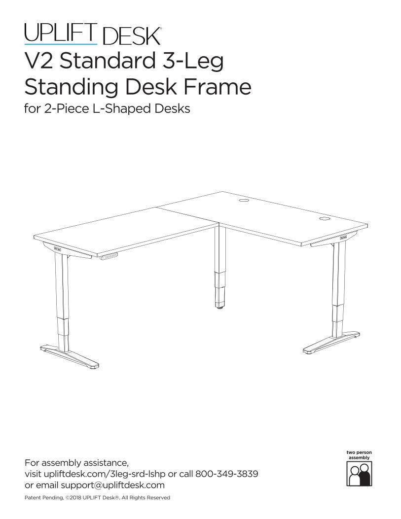
For assembly assistance,visit upliftdesk.com/3leg-srd-lshp or call 800-349-3839 or email [email protected]
two person assembly
Patent Pending, ©2018 UPLIFT Desk®. All Rights Reserved
V2 Standard 3-LegStanding Desk Framefor 2-Piece L-Shaped Desks
®

© UPLIFT Desk • 800-349-3839 • 512-614-3152 • [email protected] • upliftdesk.com2
Thank you for choosing UPLIFT Desk.
© UPLIFT Desk • 800-349-3839 • 512-614-3152 • [email protected] • upliftdesk.com 3
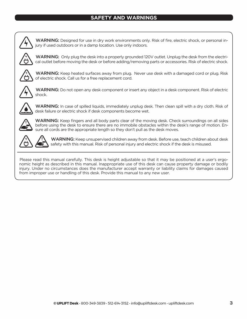
SAFETY AND WARNINGS
WARNING: Designed for use in dry work environments only. Risk of fire, electric shock, or personal in-jury if used outdoors or in a damp location. Use only indoors.
WARNING: Only plug the desk into a properly grounded 120V outlet. Unplug the desk from the electri-cal outlet before moving the desk or before adding/removing parts or accessories. Risk of electric shock.
WARNING: Do not open any desk component or insert any object in a desk component. Risk of electric shock.
WARNING: In case of spilled liquids, immediately unplug desk. Then clean spill with a dry cloth. Risk of desk failure or electric shock if desk components become wet.
WARNING: Keep heated surfaces away from plug. Never use desk with a damaged cord or plug. Risk of electric shock. Call us for a free replacement cord.
WARNING: Keep fingers and all body parts clear of the moving desk. Check surroundings on all sides before using the desk to ensure there are no immobile obstacles within the desk’s range of motion. En-sure all cords are the appropriate length so they don’t pull as the desk moves.
WARNING: Keep unsupervised children away from desk. Before use, teach children about desk safety with this manual. Risk of personal injury and electric shock if the desk is misused.
Please read this manual carefully. This desk is height adjustable so that it may be positioned at a user’s ergo-nomic height as described in this manual. Inappropriate use of this desk can cause property damage or bodily injury. Under no circumstances does the manufacturer accept warranty or liability claims for damages caused from improper use or handling of this desk. Provide this manual to any new user.
© UPLIFT Desk • 800-349-3839 • 512-614-3152 • [email protected] • upliftdesk.com4
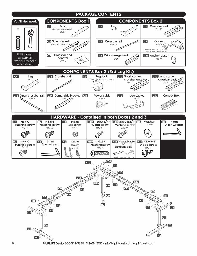
PACKAGE CONTENTS
Peg foot (includes leveling pad, qty 1)
Short cornercrossbar end (qty 1)
Long cornercrossbar end (qty 1)
Corner side bracket (qty 1)
COMPONENTS Box 3 (3rd Leg Kit)
HARDWARE - Contained in both Boxes 2 and 3M6x10
Machine screw(qty 14)
Cable mount (qty 15)
M8x8Set screw
(qty 16)
#10x3/4’’Wood screw
(qty 25)
#10-24x3/4’’Machine screw
(qty 13)
4mm Allen wrench
M8x10Machine screw
(qty 4)
M6x14 Machine screw
(qty 12)
M6x35Machine screw
(qty 4)
Support bracketor
Dogbone bolt
#10x5/8’’Wood screw
(qty 4)
5mm Allen wrench
H8
H6
H9
H5H3
H3
H3
H3
H3
H2H1
H1
H1
H1
H1
H1
H7
H4 a H4 b
H11 H14H10
H10
H10
Control BoxPower cable(qty 1)
Leg cables(qty 3)
C17C15 C16
C3
C4
C5
C9
H4a
H7
C6
H1
H2
H3
H5H4b
H6
C7
C3
C4
C5
C9
H4a
H7
C6
H1
H2
H3
H5H4b
H6
C7
COMPONENTS Box 1 COMPONENTS Box 2Leg(qty 2)
Leg(qty 1)
Crossbar end (qty 2)
Anchor plate (qty 2)
Wire management tray
Crossbar rail (qty 2)
Side bracket (right and left. qty 2)
Keypad (qty 1)
Crossbar end adapter
(qty 2)
Foot(includes leveling pads,
qty 2)
C10
C10
C4
C11
C12
C12
C13
C13
C14
C14
C6
C6
C7
C9
C9
C3
C6
C6
C6
C8
C2
C5
C5
C5
C1 C4
C4
C4
C4
C3 C4 C5
C9
H4a
H7
C6
H1 H2 H3 H5
H4b
H6
C7
C3 C4 C5
C9
H4a
H7
C6
H1 H2 H3 H5
H4b
H6
C7C3
C4
C5
C9
H4a
H7
C6
H1H2
H3H5
H4b
H6
C7
C3 C4 C5
C9
H4a
H7
C6
H1 H2 H3 H5
H4b
H6
C7
C3 C4 C5
C9
H4a
H7
C6
H1 H2 H3 H5
H4b
H6
C7
C3
C4
C5
C9
H4a
H7
C6
H1H2
H3 H5
H4b
H6
C7
C3 C4 C5
C9
H4a
H7
C6
H1 H2 H3 H5
H4b
H6
C7
C3 C4 C5
C9
H4a
H7
C6
H1 H2 H3 H5
H4b
H6
C7
or
C3
C4
C5
C9
H4a
H7
C6
H1
H2
H3
H5
H4b
H6
C7
(either in main components boxor in the desk’s accessory box)
(quantity varies per desktop)
Open crossbar rail (qty 1)
Washer (qty 13)
C1
C1
C2
C2
H2H2
H2
Crossbar rail (qty 1)
You’ll also need:
Phillips-headscrewdriver
(Wrench for Solid Wood desks)
C3
C4
C5
C9
H4a
H7
C6
H1H2
H3H5
H4b
H6
C7
© UPLIFT Desk • 800-349-3839 • 512-614-3152 • [email protected] • upliftdesk.com 5
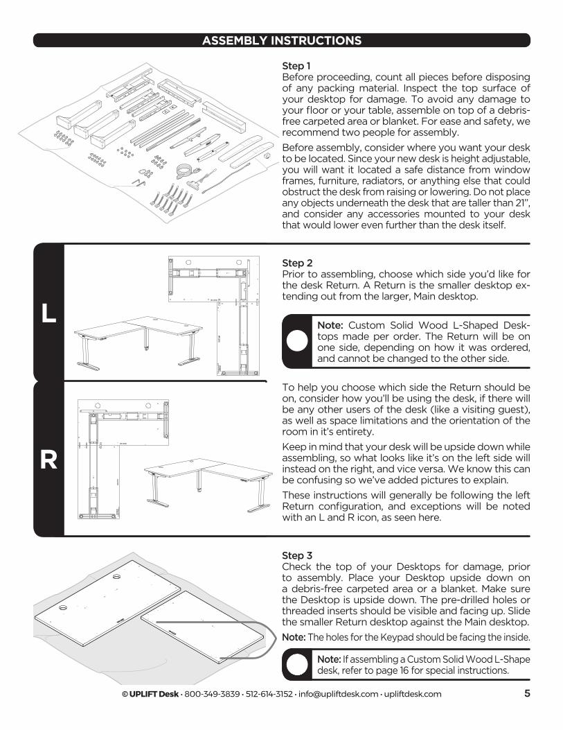
Step 2Prior to assembling, choose which side you’d like for the desk Return. A Return is the smaller desktop ex-tending out from the larger, Main desktop.
To help you choose which side the Return should be on, consider how you’ll be using the desk, if there will be any other users of the desk (like a visiting guest), as well as space limitations and the orientation of the room in it’s entirety.
Keep in mind that your desk will be upside down while assembling, so what looks like it’s on the left side will instead on the right, and vice versa. We know this can be confusing so we’ve added pictures to explain.
These instructions will generally be following the left Return configuration, and exceptions will be noted with an L and R icon, as seen here.
ASSEMBLY INSTRUCTIONS
L
R
Note: Custom Solid Wood L-Shaped Desk-tops made per order. The Return will be on one side, depending on how it was ordered, and cannot be changed to the other side.
Step 3Check the top of your Desktops for damage, prior to assembly. Place your Desktop upside down on a debris-free carpeted area or a blanket. Make sure the Desktop is upside down. The pre-drilled holes or threaded inserts should be visible and facing up. Slide the smaller Return desktop against the Main desktop.
Note: The holes for the Keypad should be facing the inside.
Note: If assembling a Custom Solid Wood L-Shape desk, refer to page 16 for special instructions.
Step 1Before proceeding, count all pieces before disposing of any packing material. Inspect the top surface of your desktop for damage. To avoid any damage to your floor or your table, assemble on top of a debris-free carpeted area or blanket. For ease and safety, we recommend two people for assembly.
Before assembly, consider where you want your desk to be located. Since your new desk is height adjustable, you will want it located a safe distance from window frames, furniture, radiators, or anything else that could obstruct the desk from raising or lowering. Do not place any objects underneath the desk that are taller than 21”, and consider any accessories mounted to your desk that would lower even further than the desk itself.
© UPLIFT Desk • 800-349-3839 • 512-614-3152 • [email protected] • upliftdesk.com6
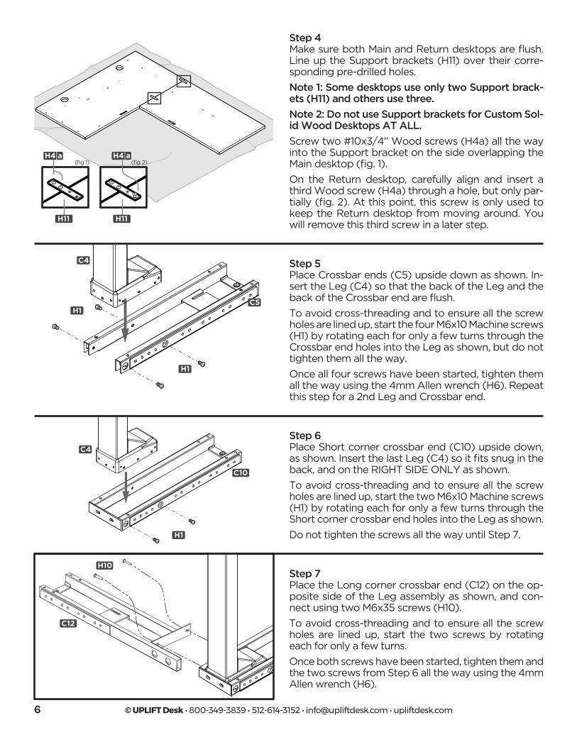
Step 4Make sure both Main and Return desktops are flush. Line up the Support brackets (H11) over their corre-sponding pre-drilled holes.
Note 1: Some desktops use only two Support brack-ets (H11) and others use three.
Note 2: Do not use Support brackets for Custom Sol-id Wood Desktops AT ALL.
Screw two #10x3/4’’ Wood screws (H4a) all the way into the Support bracket on the side overlapping the Main desktop (fig. 1).
On the Return desktop, carefully align and insert a third Wood screw (H4a) through a hole, but only par-tially (fig. 2). At this point, this screw is only used to keep the Return desktop from moving around. You will remove this third screw in a later step.
(fig 1) (fig 2)H4 a
H11 H11
Step 6Place Short corner crossbar end (C10) upside down, as shown. Insert the last Leg (C4) so it fits snug in the back, and on the RIGHT SIDE ONLY as shown.
To avoid cross-threading and to ensure all the screw holes are lined up, start the two M6x10 Machine screws (H1) by rotating each for only a few turns through the Short corner crossbar end holes into the Leg as shown.
Do not tighten the screws all the way until Step 7.
C5
C4
C4
H1
H1
H1
C10
Step 5Place Crossbar ends (C5) upside down as shown. In-sert the Leg (C4) so that the back of the Leg and the back of the Crossbar end are flush.
To avoid cross-threading and to ensure all the screw holes are lined up, start the four M6x10 Machine screws (H1) by rotating each for only a few turns through the Crossbar end holes into the Leg as shown, but do not tighten them all the way.
Once all four screws have been started, tighten them all the way using the 4mm Allen wrench (H6). Repeat this step for a 2nd Leg and Crossbar end.
C12
H10 Step 7Place the Long corner crossbar end (C12) on the op-posite side of the Leg assembly as shown, and con-nect using two M6x35 screws (H10).
To avoid cross-threading and to ensure all the screw holes are lined up, start the two screws by rotating each for only a few turns.
Once both screws have been started, tighten them and the two screws from Step 6 all the way using the 4mm Allen wrench (H6).
H4 a
© UPLIFT Desk • 800-349-3839 • 512-614-3152 • [email protected] • upliftdesk.com 7
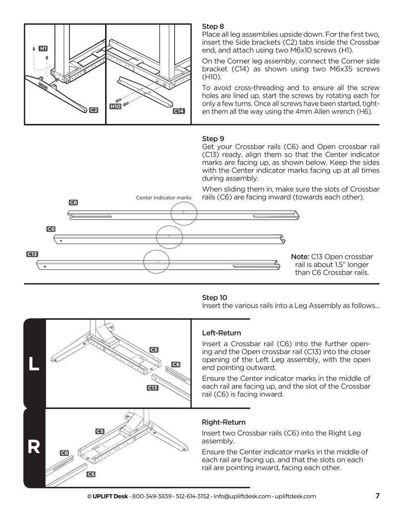
Step 8Place all leg assemblies upside down. For the first two, insert the Side brackets (C2) tabs inside the Crossbar end, and attach using two M6x10 screws (H1).
On the Corner leg assembly, connect the Corner side bracket (C14) as shown using two M6x35 screws (H10).
To avoid cross-threading and to ensure all the screw holes are lined up, start the screws by rotating each for only a few turns. Once all screws have been started, tight-en them all the way using the 4mm Allen wrench (H6).
H1
C2 C14H10
Step 9Get your Crossbar rails (C6) and Open crossbar rail (C13) ready, align them so that the Center indicator marks are facing up, as shown below. Keep the sides with the Center indicator marks facing up at all times during assembly.
When sliding them in, make sure the slots of Crossbar rails (C6) are facing inward (towards each other).
Note: C13 Open crossbar rail is about 1.5’’ longer than C6 Crossbar rails.
Center indicator marksC6
C6
C13
Step 10Insert the various rails into a Leg Assembly as follows...
L
R
Right-Return
Insert two Crossbar rails (C6) into the Right Leg assembly.
Ensure the Center indicator marks in the middle of each rail are facing up, and that the slots on each rail are pointing inward, facing each other.
C5
C5
C6
C6
C6
C13
Left-Return
Insert a Crossbar rail (C6) into the further open-ing and the Open crossbar rail (C13) into the closer opening of the Left Leg assembly, with the open end pointing outward.
Ensure the Center indicator marks in the middle of each rail are facing up, and the slot of the Crossbar rail (C6) is facing inward.
© UPLIFT Desk • 800-349-3839 • 512-614-3152 • [email protected] • upliftdesk.com8
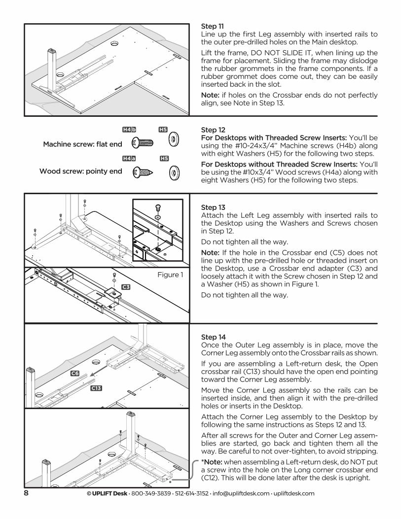
Step 11Line up the first Leg assembly with inserted rails to the outer pre-drilled holes on the Main desktop.
Lift the frame, DO NOT SLIDE IT, when lining up the frame for placement. Sliding the frame may dislodge the rubber grommets in the frame components. If a rubber grommet does come out, they can be easily inserted back in the slot.
Note: if holes on the Crossbar ends do not perfectly align, see Note in Step 13.
Step 12For Desktops with Threaded Screw Inserts: You’ll be using the #10-24x3/4” Machine screws (H4b) along with eight Washers (H5) for the following two steps.
For Desktops without Threaded Screw Inserts: You’ll be using the #10x3/4” Wood screws (H4a) along with eight Washers (H5) for the following two steps.
Machine screw: flat end
Wood screw: pointy end
H4 b
H4 a
C3
C4
C5
C9
H4a
H7
C6
H1
H2
H3
H5H4b
H6
C7
C3
C4
C5
C9
H4a
H7
C6
H1
H2
H3
H5H4b
H6
C7
C3
C4
C5
C9
H4a
H7
C6
H1
H2
H3
H5H4b
H6
C7
C3
C4
C5
C9
H4a
H7
C6
H1
H2
H3
H5H4b
H6
C7
H5
H5
Step 13Attach the Left Leg assembly with inserted rails to the Desktop using the Washers and Screws chosen in Step 12.
Do not tighten all the way.
Note: If the hole in the Crossbar end (C5) does not line up with the pre-drilled hole or threaded insert on the Desktop, use a Crossbar end adapter (C3) and loosely attach it with the Screw chosen in Step 12 and a Washer (H5) as shown in Figure 1.
Do not tighten all the way.
Figure 1
C3
*
Step 14Once the Outer Leg assembly is in place, move the Corner Leg assembly onto the Crossbar rails as shown.
If you are assembling a Left-return desk, the Open crossbar rail (C13) should have the open end pointing toward the Corner Leg assembly.
Move the Corner Leg assembly so the rails can be inserted inside, and then align it with the pre-drilled holes or inserts in the Desktop.
Attach the Corner Leg assembly to the Desktop by following the same instructions as Steps 12 and 13.
After all screws for the Outer and Corner Leg assem-blies are started, go back and tighten them all the way. Be careful to not over-tighten, to avoid stripping.
*Note: when assembling a Left-return desk, do NOT put a screw into the hole on the Long corner crossbar end (C12). This will be done later after the desk is upright.
C13
C6
© UPLIFT Desk • 800-349-3839 • 512-614-3152 • [email protected] • upliftdesk.com 9
L
RC5
C6
C13
C5
C6
C6
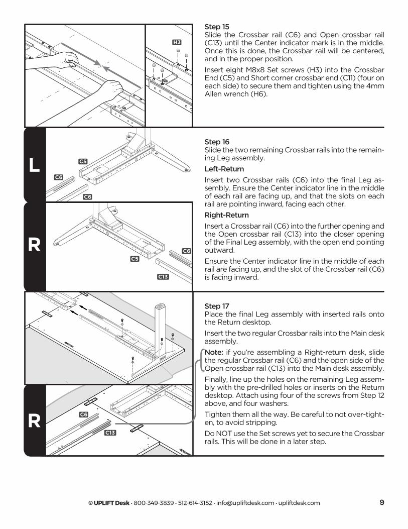
Step 15Slide the Crossbar rail (C6) and Open crossbar rail (C13) until the Center indicator mark is in the middle. Once this is done, the Crossbar rail will be centered, and in the proper position.
Insert eight M8x8 Set screws (H3) into the Crossbar End (C5) and Short corner crossbar end (C11) (four on each side) to secure them and tighten using the 4mm Allen wrench (H6).
H3
Step 16Slide the two remaining Crossbar rails into the remain-ing Leg assembly.
Left-Return
Insert two Crossbar rails (C6) into the final Leg as-sembly. Ensure the Center indicator line in the middle of each rail are facing up, and that the slots on each rail are pointing inward, facing each other.
Right-Return
Insert a Crossbar rail (C6) into the further opening and the Open crossbar rail (C13) into the closer opening of the Final Leg assembly, with the open end pointing outward.
Ensure the Center indicator line in the middle of each rail are facing up, and the slot of the Crossbar rail (C6) is facing inward.
R
Step 17Place the final Leg assembly with inserted rails onto the Return desktop.
Insert the two regular Crossbar rails into the Main desk assembly.
Note: if you’re assembling a Right-return desk, slide the regular Crossbar rail (C6) and the open side of the Open crossbar rail (C13) into the Main desk assembly.
Finally, line up the holes on the remaining Leg assem-bly with the pre-drilled holes or inserts on the Return desktop. Attach using four of the screws from Step 12 above, and four washers.
Tighten them all the way. Be careful to not over-tight-en, to avoid stripping.
Do NOT use the Set screws yet to secure the Crossbar rails. This will be done in a later step.
C13
C6
© UPLIFT Desk • 800-349-3839 • 512-614-3152 • [email protected] • upliftdesk.com10
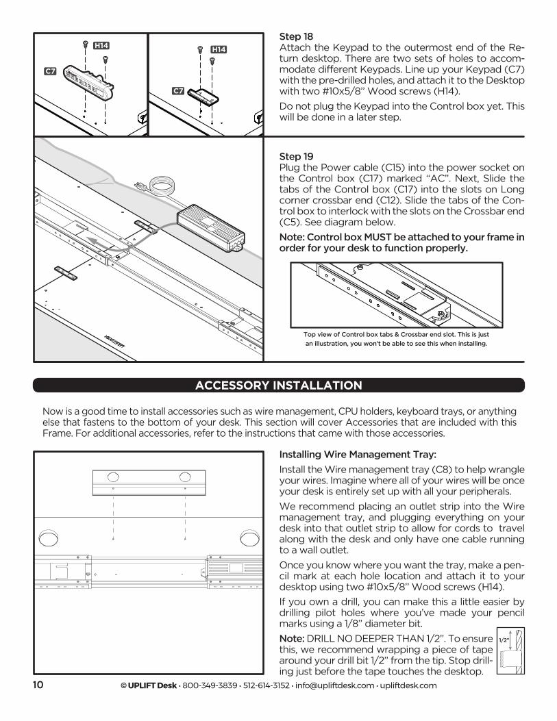
Step 18Attach the Keypad to the outermost end of the Re-turn desktop. There are two sets of holes to accom-modate different Keypads. Line up your Keypad (C7) with the pre-drilled holes, and attach it to the Desktop with two #10x5/8’’ Wood screws (H14).
Do not plug the Keypad into the Control box yet. This will be done in a later step.
C7
C7
H14 H14
Step 19Plug the Power cable (C15) into the power socket on the Control box (C17) marked “AC”. Next, Slide the tabs of the Control box (C17) into the slots on Long corner crossbar end (C12). Slide the tabs of the Con-trol box to interlock with the slots on the Crossbar end (C5). See diagram below.
Note: Control box MUST be attached to your frame in order for your desk to function properly.
Top view of Control box tabs & Crossbar end slot. This is just
an illustration, you won’t be able to see this when installing.
Now is a good time to install accessories such as wire management, CPU holders, keyboard trays, or anything else that fastens to the bottom of your desk. This section will cover Accessories that are included with this Frame. For additional accessories, refer to the instructions that came with those accessories.
ACCESSORY INSTALLATION
Installing Wire Management Tray:
Install the Wire management tray (C8) to help wrangle your wires. Imagine where all of your wires will be once your desk is entirely set up with all your peripherals.
We recommend placing an outlet strip into the Wire management tray, and plugging everything on your desk into that outlet strip to allow for cords to travel along with the desk and only have one cable running to a wall outlet.
Once you know where you want the tray, make a pen-cil mark at each hole location and attach it to your desktop using two #10x5/8’’ Wood screws (H14).
If you own a drill, you can make this a little easier by drilling pilot holes where you’ve made your pencil marks using a 1/8” diameter bit.
Note: DRILL NO DEEPER THAN 1/2”. To ensure this, we recommend wrapping a piece of tape around your drill bit 1/2” from the tip. Stop drill-ing just before the tape touches the desktop.
1/2’’
© UPLIFT Desk • 800-349-3839 • 512-614-3152 • [email protected] • upliftdesk.com 11
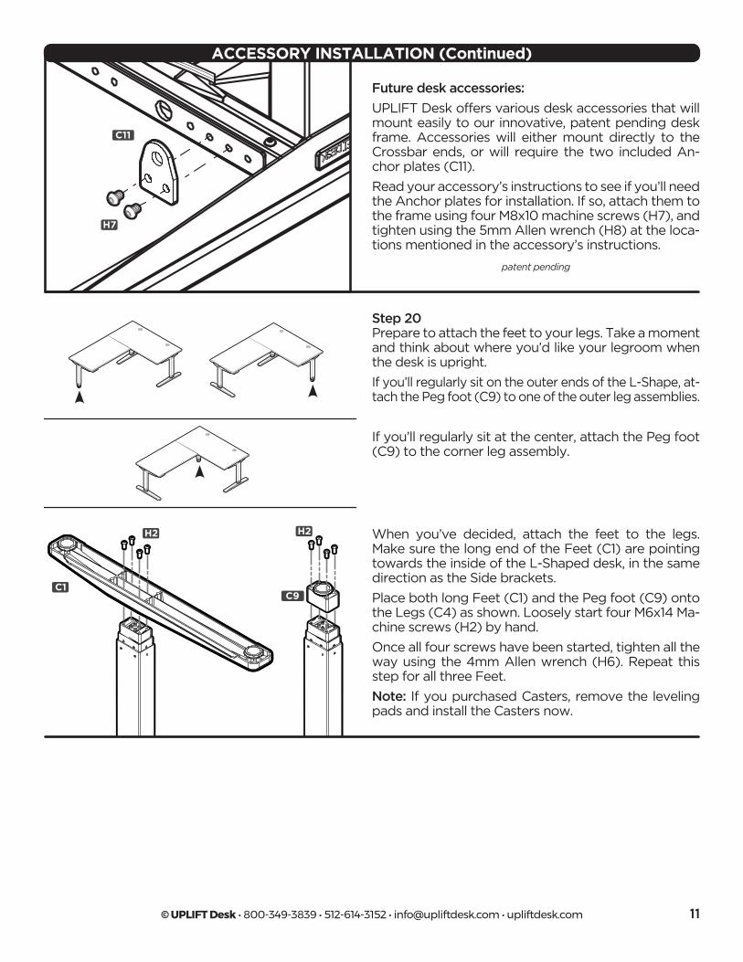
Future desk accessories:
UPLIFT Desk offers various desk accessories that will mount easily to our innovative, patent pending desk frame. Accessories will either mount directly to the Crossbar ends, or will require the two included An-chor plates (C11).
Read your accessory’s instructions to see if you’ll need the Anchor plates for installation. If so, attach them to the frame using four M8x10 machine screws (H7), and tighten using the 5mm Allen wrench (H8) at the loca-tions mentioned in the accessory’s instructions.
C11
H7
patent pending
ACCESSORY INSTALLATION (Continued)
C1
H2 H2
C9
Step 20Prepare to attach the feet to your legs. Take a moment and think about where you’d like your legroom when the desk is upright.
If you’ll regularly sit on the outer ends of the L-Shape, at-tach the Peg foot (C9) to one of the outer leg assemblies.
If you’ll regularly sit at the center, attach the Peg foot (C9) to the corner leg assembly.
When you’ve decided, attach the feet to the legs. Make sure the long end of the Feet (C1) are pointing towards the inside of the L-Shaped desk, in the same direction as the Side brackets.
Place both long Feet (C1) and the Peg foot (C9) onto the Legs (C4) as shown. Loosely start four M6x14 Ma-chine screws (H2) by hand.
Once all four screws have been started, tighten all the way using the 4mm Allen wrench (H6). Repeat this step for all three Feet.
Note: If you purchased Casters, remove the leveling pads and install the Casters now.
© UPLIFT Desk • 800-349-3839 • 512-614-3152 • [email protected] • upliftdesk.com12
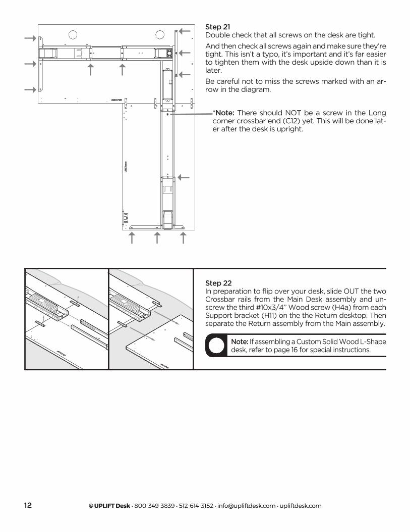
Step 21Double check that all screws on the desk are tight.
And then check all screws again and make sure they’re tight. This isn’t a typo, it’s important and it’s far easier to tighten them with the desk upside down than it is later.
Be careful not to miss the screws marked with an ar-row in the diagram.
*Note: There should NOT be a screw in the Long corner crossbar end (C12) yet. This will be done lat-er after the desk is upright.
Step 22In preparation to flip over your desk, slide OUT the two Crossbar rails from the Main Desk assembly and un-screw the third #10x3/4’’ Wood screw (H4a) from each Support bracket (H11) on the the Return desktop. Then separate the Return assembly from the Main assembly.
Note: If assembling a Custom Solid Wood L-Shape desk, refer to page 16 for special instructions.
*
© UPLIFT Desk • 800-349-3839 • 512-614-3152 • [email protected] • upliftdesk.com 13
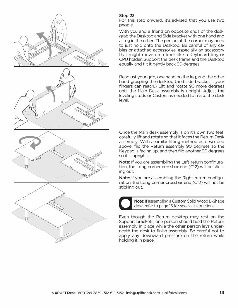
Step 23For this step onward, it’s advised that you use two people.
With you and a friend on opposite ends of the desk, grab the Desktop and Side bracket with one hand and a Leg in the other. The person at the corner may need to just hold onto the Desktop. Be careful of any ca-bles or attached accessories, especially an accessory that might move on a track like a Keyboard tray or CPU holder. Support the desk frame and the Desktop equally and tilt it gently back 90 degrees.
Readjust your grip, one hand on the leg, and the other hand grasping the desktop (and side bracket if your fingers can reach.) Lift and rotate 90 more degrees until the Main Desk assembly is upright. Adjust the leveling studs or Casters as needed to make the desk level.
Once the Main desk assembly is on it’s own two feet, carefully lift and rotate so that it faces the Return Desk assembly. With a similar lifting method as described above, flip the Return assembly 90 degrees so the Keypad is facing up, and then flip another 90 degrees so it is upright.
Note: If you are assembling the Left-return configura-tion, the Long corner crossbar end (C12) will be stick-ing out.
Note: If you are assembling the Right-return configu-ration, the Long corner crossbar end (C12) will not be sticking out.
Even though the Return desktop may rest on the Support brackets, one person should hold the Return assembly in place while the other person lays under-neath the desk to finish assembly. Be careful not to apply any downward pressure on the return while holding it in place.
Note: If assembling a Custom Solid Wood L-Shape desk, refer to page 16 for special instructions.
© UPLIFT Desk • 800-349-3839 • 512-614-3152 • [email protected] • upliftdesk.com14
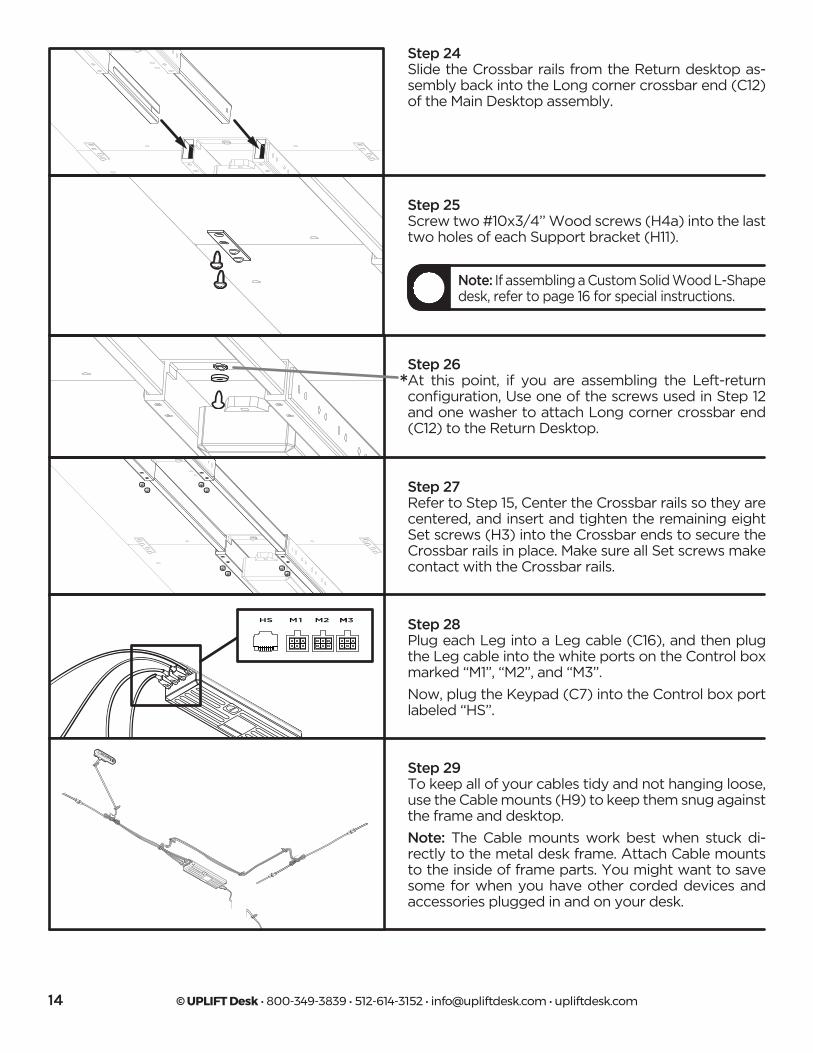
Step 27Refer to Step 15, Center the Crossbar rails so they are centered, and insert and tighten the remaining eight Set screws (H3) into the Crossbar ends to secure the Crossbar rails in place. Make sure all Set screws make contact with the Crossbar rails.
Step 28Plug each Leg into a Leg cable (C16), and then plug the Leg cable into the white ports on the Control box marked “M1”, “M2”, and “M3”.
Now, plug the Keypad (C7) into the Control box port labeled “HS”.
Step 24Slide the Crossbar rails from the Return desktop as-sembly back into the Long corner crossbar end (C12) of the Main Desktop assembly.
Step 25Screw two #10x3/4’’ Wood screws (H4a) into the last two holes of each Support bracket (H11).
Step 26At this point, if you are assembling the Left-return configuration, Use one of the screws used in Step 12 and one washer to attach Long corner crossbar end (C12) to the Return Desktop.
Note: If assembling a Custom Solid Wood L-Shape desk, refer to page 16 for special instructions.
Step 29To keep all of your cables tidy and not hanging loose, use the Cable mounts (H9) to keep them snug against the frame and desktop.
Note: The Cable mounts work best when stuck di-rectly to the metal desk frame. Attach Cable mounts to the inside of frame parts. You might want to save some for when you have other corded devices and accessories plugged in and on your desk.
*
© UPLIFT Desk • 800-349-3839 • 512-614-3152 • [email protected] • upliftdesk.com 15
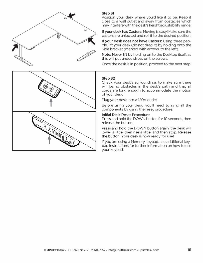
Step 31Position your desk where you’d like it to be. Keep it close to a wall outlet and away from obstacles which may interfere with the desk’s height adjustability range.
If your desk has Casters: Moving is easy! Make sure the casters are unlocked and roll it to the desired position.
If your desk does not have Casters: Using three peo-ple, lift your desk (do not drag it) by holding onto the Side bracket (marked with arrows, to the left).
Note: Never lift by holding on to the Desktop itself, as this will put undue stress on the screws.
Once the desk is in position, proceed to the next step.
Step 32 Check your desk’s surroundings to make sure there will be no obstacles in the desk’s path and that all cords are long enough to accommodate the motion of your desk.
Plug your desk into a 120V outlet.
Before using your desk, you’ll need to sync all the components by using the reset procedure.
Initial Desk Reset ProcedurePress and hold the DOWN button for 10 seconds, then release the button.
Press and hold the DOWN button again, the desk will lower a little, then rise a little, and then stop. Release the button. Your desk is now ready for use!
If you are using a Memory keypad, see additional key-pad instructions for further information on how to use your keypad.
© UPLIFT Desk • 800-349-3839 • 512-614-3152 • [email protected] • upliftdesk.com16
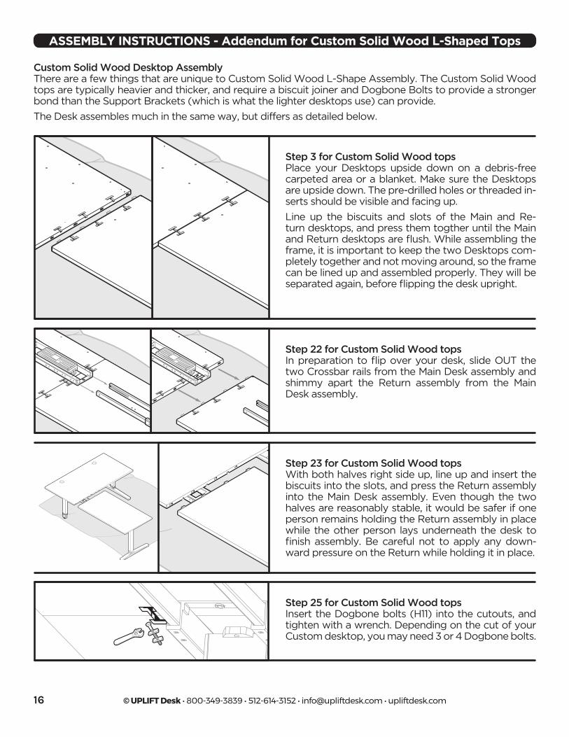
Step 3 for Custom Solid Wood topsPlace your Desktops upside down on a debris-free carpeted area or a blanket. Make sure the Desktops are upside down. The pre-drilled holes or threaded in-serts should be visible and facing up.
Line up the biscuits and slots of the Main and Re-turn desktops, and press them togther until the Main and Return desktops are flush. While assembling the frame, it is important to keep the two Desktops com-pletely together and not moving around, so the frame can be lined up and assembled properly. They will be separated again, before flipping the desk upright.
Custom Solid Wood Desktop AssemblyThere are a few things that are unique to Custom Solid Wood L-Shape Assembly. The Custom Solid Wood tops are typically heavier and thicker, and require a biscuit joiner and Dogbone Bolts to provide a stronger bond than the Support Brackets (which is what the lighter desktops use) can provide.
The Desk assembles much in the same way, but differs as detailed below.
Step 22 for Custom Solid Wood topsIn preparation to flip over your desk, slide OUT the two Crossbar rails from the Main Desk assembly and shimmy apart the Return assembly from the Main Desk assembly.
Step 23 for Custom Solid Wood topsWith both halves right side up, line up and insert the biscuits into the slots, and press the Return assembly into the Main Desk assembly. Even though the two halves are reasonably stable, it would be safer if one person remains holding the Return assembly in place while the other person lays underneath the desk to finish assembly. Be careful not to apply any down-ward pressure on the Return while holding it in place.
Step 25 for Custom Solid Wood topsInsert the Dogbone bolts (H11) into the cutouts, and tighten with a wrench. Depending on the cut of your Custom desktop, you may need 3 or 4 Dogbone bolts.
ASSEMBLY INSTRUCTIONS - Addendum for Custom Solid Wood L-Shaped Tops
© UPLIFT Desk • 800-349-3839 • 512-614-3152 • [email protected] • upliftdesk.com 17
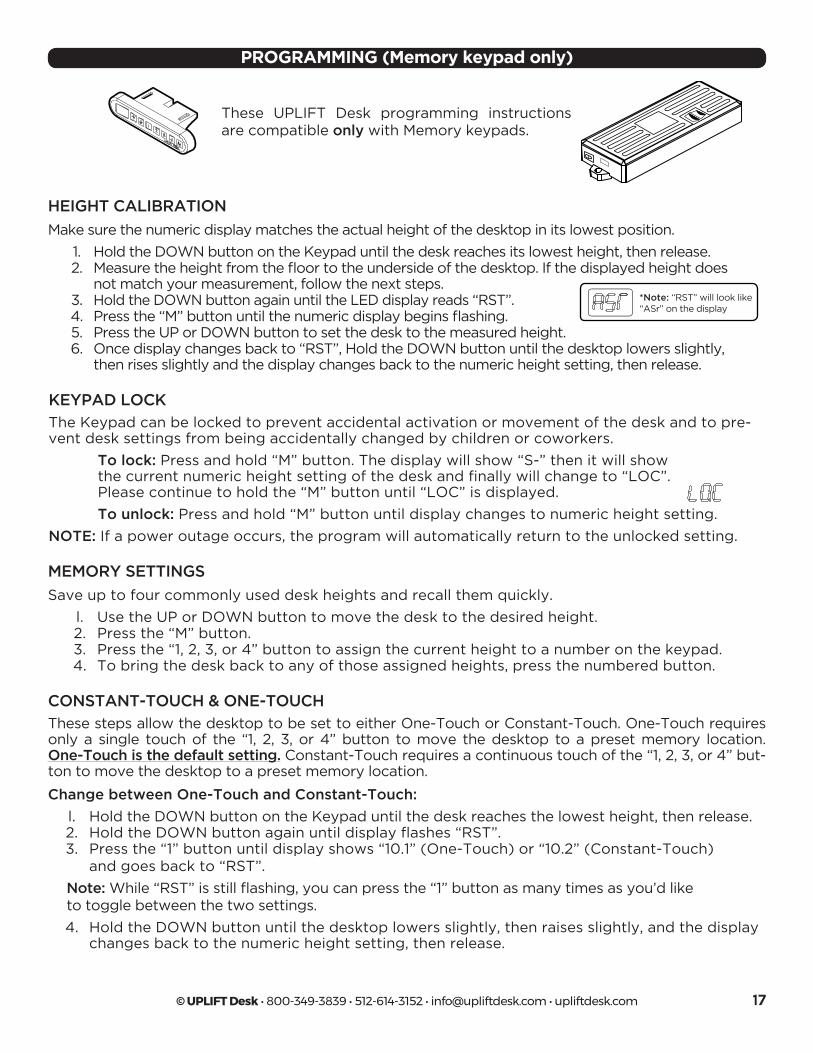
These UPLIFT Desk programming instructions are compatible only with Memory keypads.
HEIGHT CALIBRATION
Make sure the numeric display matches the actual height of the desktop in its lowest position.
1. Hold the DOWN button on the Keypad until the desk reaches its lowest height, then release. 2. Measure the height from the floor to the underside of the desktop. If the displayed height does not match your measurement, follow the next steps. 3. Hold the DOWN button again until the LED display reads “RST”. 4. Press the “M” button until the numeric display begins flashing. 5. Press the UP or DOWN button to set the desk to the measured height. 6. Once display changes back to “RST”, Hold the DOWN button until the desktop lowers slightly, then rises slightly and the display changes back to the numeric height setting, then release.
*Note: “RST” will look like“ASr” on the display
PROGRAMMING (Memory keypad only)
C3 C4 C5
C9
H4a
H7
C6
H1 H2 H3 H5
H4b
H6
C7
MEMORY SETTINGS
Save up to four commonly used desk heights and recall them quickly.
l. Use the UP or DOWN button to move the desk to the desired height. 2. Press the “M” button. 3. Press the “1, 2, 3, or 4” button to assign the current height to a number on the keypad. 4. To bring the desk back to any of those assigned heights, press the numbered button.
CONSTANT-TOUCH & ONE-TOUCH
These steps allow the desktop to be set to either One-Touch or Constant-Touch. One-Touch requires only a single touch of the “1, 2, 3, or 4” button to move the desktop to a preset memory location. One-Touch is the default setting. Constant-Touch requires a continuous touch of the “1, 2, 3, or 4” but-ton to move the desktop to a preset memory location.
Change between One-Touch and Constant-Touch:
l. Hold the DOWN button on the Keypad until the desk reaches the lowest height, then release. 2. Hold the DOWN button again until display flashes “RST”. 3. Press the “1” button until display shows “10.1” (One-Touch) or “10.2” (Constant-Touch) and goes back to “RST”.
Note: While “RST” is still flashing, you can press the “1” button as many times as you’d like to toggle between the two settings.
4. Hold the DOWN button until the desktop lowers slightly, then raises slightly, and the display changes back to the numeric height setting, then release.
KEYPAD LOCK
The Keypad can be locked to prevent accidental activation or movement of the desk and to pre-vent desk settings from being accidentally changed by children or coworkers.
To lock: Press and hold “M” button. The display will show “S-” then it will show the current numeric height setting of the desk and finally will change to “LOC”. Please continue to hold the “M” button until “LOC” is displayed.
To unlock: Press and hold “M” button until display changes to numeric height setting.
NOTE: If a power outage occurs, the program will automatically return to the unlocked setting.
© UPLIFT Desk • 800-349-3839 • 512-614-3152 • [email protected] • upliftdesk.com18
PROGRAMMING (continued)
DISPLAY UNITS
Change the numeric display to show heights in either inches or centimeters.
l. Hold the DOWN button on the Keypad until the desk reaches the lowest height, then release. 2. Hold the DOWN button again until display flashes “RST”. 3. Press the “2” button until display shows “10.3” (centimeters) or “10.4” (inches) and goes back to “RST”.
Note: While “RST” is still flashing, you can press the “2” button as many times as you’d like to toggle between the two settings.
4. Hold the DOWN button until the desktop lowers slightly, then raises slightly, and the display changes back to the numeric height setting, then release.
MINIMUM & MAXIMUM HEIGHT SETTINGS
The desk frame ships with default minimum and maximum height limits. These steps allow the upper and lower limits to be changed to your preference.
Note: If memory settings were previously set outside of the new minimum and maximum height settings, they will default to the new minimum and maximum settings. To set new minimum and maximum height settings outside of the current settings, you will need to first remove the current minimum and maximum settings.
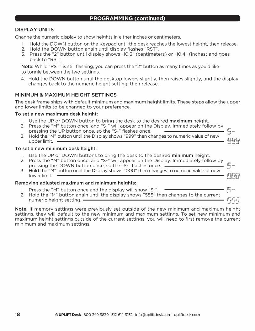
To set a new maximum desk height:
l. Use the UP or DOWN button to bring the desk to the desired maximum height. 2. Press the “M” button once, and “S-” will appear on the Display. Immediately follow by pressing the UP button once, so the “S-” flashes once. 3. Hold the “M” button until the Display shows “999” then changes to numeric value of new upper limit.
To set a new minimum desk height:
l. Use the UP or DOWN buttons to bring the desk to the desired minimum height. 2. Press the “M” button once, and “S-” will appear on the Display. Immediately follow by pressing the DOWN button once, so the “S-” flashes once. 3. Hold the “M” button until the Display shows “000” then changes to numeric value of new lower limit.
Removing adjusted maximum and minimum heights:
l. Press the “M” button once and the display will show “S-”. 2. Hold the “M” button again until the display shows “555” then changes to the current numeric height setting.
© UPLIFT Desk • 800-349-3839 • 512-614-3152 • [email protected] • upliftdesk.com 19
If your desk does not respond when you try to raise it or lower it, or if the Keypad displays error messages (“EO1” through “EO12”), check to make sure all the cables are secure (Legs to cables, cables to Control box). If the problem persists, perform the reset procedure below.
If the error message persists after performing the Reset procedure, or if there is a height difference between the legs which exceeds 1.5’’, contact UPLIFT Desk at the email address or phone numbers listed at the bot-tom of each page of these instructions.
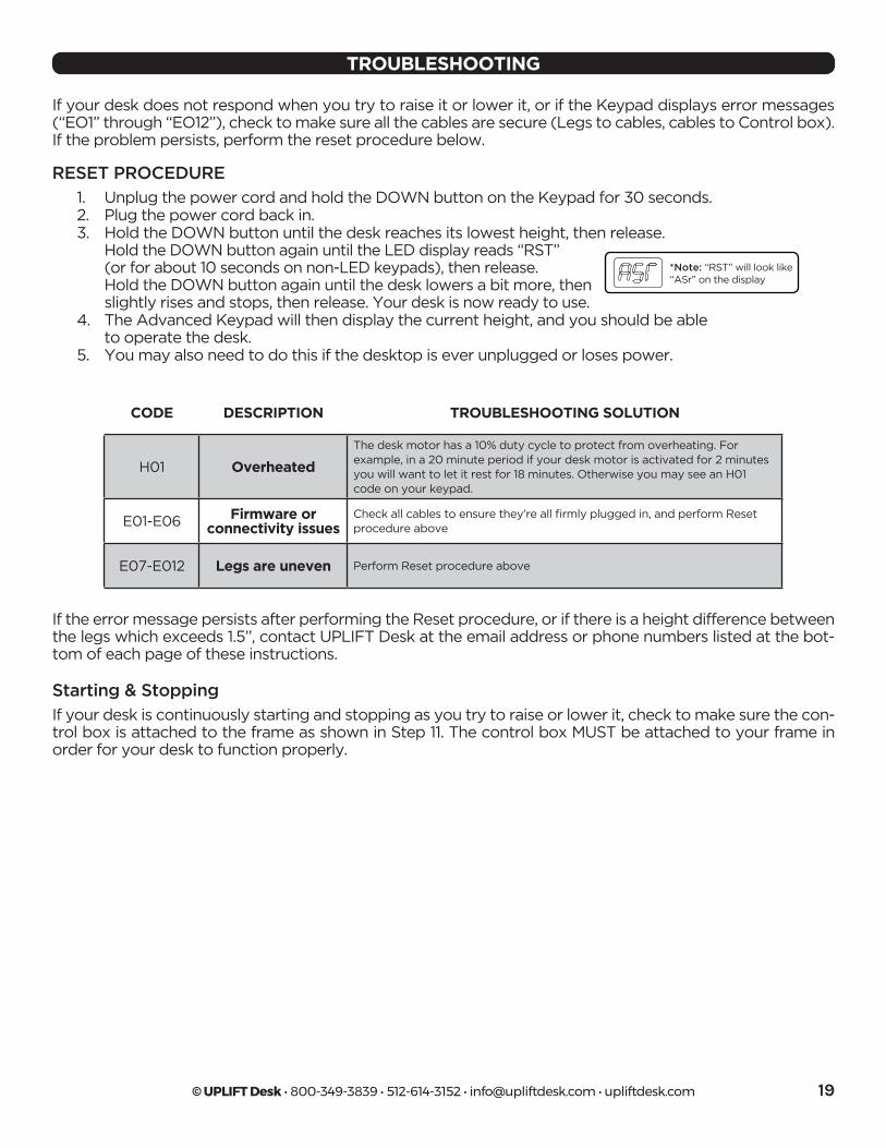
*Note: “RST” will look like“ASr” on the display
RESET PROCEDURE
1. Unplug the power cord and hold the DOWN button on the Keypad for 30 seconds. 2. Plug the power cord back in. 3. Hold the DOWN button until the desk reaches its lowest height, then release.
Hold the DOWN button again until the LED display reads “RST” (or for about 10 seconds on non-LED keypads), then release. Hold the DOWN button again until the desk lowers a bit more, then slightly rises and stops, then release. Your desk is now ready to use.
4. The Advanced Keypad will then display the current height, and you should be able to operate the desk.
5. You may also need to do this if the desktop is ever unplugged or loses power.
TROUBLESHOOTING
CODE DESCRIPTION TROUBLESHOOTING SOLUTION
H01 Overheated
The desk motor has a 10% duty cycle to protect from overheating. For example, in a 20 minute period if your desk motor is activated for 2 minutes you will want to let it rest for 18 minutes. Otherwise you may see an H01 code on your keypad.
E01-E06 Firmware or connectivity issues
Check all cables to ensure they’re all firmly plugged in, and perform Reset procedure above
E07-E012 Legs are uneven Perform Reset procedure above
Starting & Stopping
If your desk is continuously starting and stopping as you try to raise or lower it, check to make sure the con-trol box is attached to the frame as shown in Step 11. The control box MUST be attached to your frame in order for your desk to function properly.

Work Better. Live Healthier
Copyright Notice: This guide is a component of the UPLIFT Desk™. This guide is a part of the scope of delivery, even if the item is resold. This guide is also available on the UPLIFT Desk website: upliftdesk.com. Excerpts or copies may not be forwarded to third parties or used in any other published form without the prior written consent of UPLIFT Desk. These instructions are subject to United States copyright law.
©
SAVE THESE INSTRUCTIONSStudy this manual carefully. If this desk is sold, please provide this manual to the buyer, installers, or support personnel operating the product.
®
90.014.01.0648v.C - AI-FRMA-3-SRD-LSHP-2.1
4933053185232 - THS0654933053185232