v1sr v3s v3sr v3srb v4s v4sr v4srb - cdviberica.com ventosas de superficie...ventosas...
TRANSCRIPT
The installer’s choicecdvigroup.com
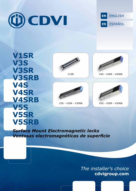
V1SRV3SV3SRV3SRBV4SV4SRV4SRBV5SV5SRV5SRBSurface Mount Electromagnetic locksVentosas electromagnéticas de superficie
V3S - V3SR - V3SRB
V1SR V4S - V4SR - V4SRB
V5SRBV5S - V5SR - V5SRB
ENGLISHEN
ESPAÑOLES
1] PRODUCT PRESENTATION
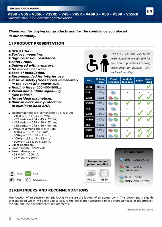
The V3S, V4S and V5S series
with signalling are suitable for
the new regulations covering
assistance to persons with
reduced mobility.
Thank you for buying our products and for the confidence you placedin our company.
NFS 61-937. Surface mounting. High corrosion resistance. Safety rope. Delivered with armature. No mechanical wear. Ease of installation. Recommended for interior use. Positive safety (frees access immediately
in the event of a power cut). Holding force: 300/400/500kg. Visual and audible signalling
(see table)*. No residual magnetism. Built-in electronic protection
to eliminate back EMF.
Electromagnetic lock dimensions (L x W x D): - V1SR = 167 x 34 x 21mm. - V3S series = 254 x 45 x 27mm, - V4S series = 254 x 50 x 27mm, - V5S series = 272 x 66 x 40mm. Armature dimensions (l x w x d):
- 180kg = 130 x 32 x 9mm, - 300kg = 185 x 38 x 11mm, - 400kg= 185 x 45 x 12mm, - 500kg = 185 x 60 x 12mm. Silent operation. Power supply: 12/24V dc. Power absorption:
- 12 V DC = 500mA, - 24 V DC = 250mA.
Refs Holding force
Visualfeedback
Audiblefeedback Relay Moni-
tored
V1SR 180 kg - - -
V3S 300kg - - -
V3SR 300kg -
V3SRB 300kg
V4S 400kg - - -
V4SR 400kg -
V4SRB 400kg
V5S 500kg - - -
V5SR 500kg -
V5SRB 500kg
EC certification
WEEE
IP42
2 cdvigroup.com
COlOUR CODES
BlUE ACTIVE VOLTAGE
RED LOCKED
GREEN OPEN
BlUE LOCKED
GREEN OPEN + BUZZER
RoHS
ARD212 BS60
Recommended power supplies
* Depending on the version.
2] REMINDERS AND RECOMMENDATIONS
The function of an electromagnetic lock is to ensure the locking of an access point. This document is a guide of installation which will allow you to secure the installation according to the characteristics of the product, the site and the environmental requirements.
ENV1SR - V3S - V3SR - V3SRB - V4S - V4SR - V4SRB - V5S - V5SR - V5SRBSurface mount Electromagnetic locks
INSTAllATION MANUAl
3cdvigroup.com
POwER SUPPlyAn electromagnetic lock always operates in DC current, a very low safety voltage. The Diax® electromagnetic lock is recommended for use with power supplies manufactured by CDVI, however, other power supplies may be used on condition that they are of equivalent quality and characteristics rectified, filtered, regulated and protected by fuse in primary and secondary sectors.
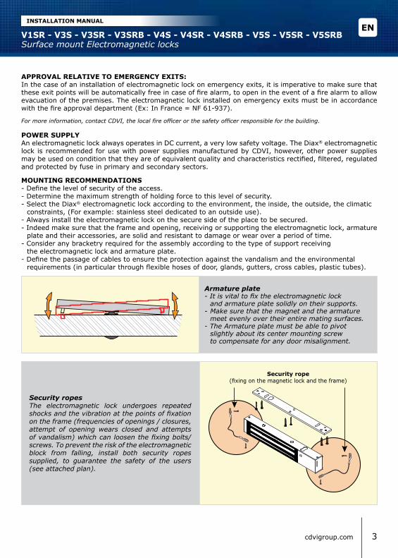
MOUNTING RECOMMENDATIONS- Define the level of security of the access.- Determine the maximum strength of holding force to this level of security.- Select the Diax® electromagnetic lock according to the environment, the inside, the outside, the climatic constraints, (For example: stainless steel dedicated to an outside use).- Always install the electromagnetic lock on the secure side of the place to be secured.- Indeed make sure that the frame and opening, receiving or supporting the electromagnetic lock, armature plate and their accessories, are solid and resistant to damage or wear over a period of time. - Consider any bracketry required for the assembly according to the type of support receiving the electromagnetic lock and armature plate.- Define the passage of cables to ensure the protection against the vandalism and the environmental requirements (in particular through flexible hoses of door, glands, gutters, cross cables, plastic tubes).
Security ropesThe electromagnetic lock undergoes repeated shocks and the vibration at the points of fixation on the frame (frequencies of openings / closures, attempt of opening wears closed and attempts of vandalism) which can loosen the fixing bolts/screws. To prevent the risk of the electromagnetic block from falling, install both security ropes supplied, to guarantee the safety of the users (see attached plan).
Security rope(fixing on the magnetic lock and the frame)
APPROVAl RElATIVE TO EMERGENCy ExITS:In the case of an installation of electromagnetic lock on emergency exits, it is imperative to make sure that these exit points will be automatically free in case of fire alarm, to open in the event of a fire alarm to allow evacuation of the premises. The electromagnetic lock installed on emergency exits must be in accordance with the fire approval department (Ex: In France = NF 61-937).
For more information, contact CDVI, the local fire officer or the safety officer responsible for the building.
Armature plate- It is vital to fix the electromagnetic lock and armature plate solidly on their supports.- Make sure that the magnet and the armature meet evenly over their entire mating surfaces.- The Armature plate must be able to pivot slightly about its center mounting screw to compensate for any door misalignment.
ENV1SR - V3S - V3SR - V3SRB - V4S - V4SR - V4SRB - V5S - V5SR - V5SRBSurface mount Electromagnetic locks
INSTAllATION MANUAl

3] PACKAGE CONTENTS
Surfacemount
magneticlock
Armatureplate
Fixingplate
Roll pin5x16
Steelwasher
4x25woodscrew
Key3mm
Key5mm
1 1 1 2 2 7 1 1
M8x35screw
M8x25screw
3x8 self-tapping
screw
Guidepiece
Capnut
Safetyrope
Rubberwasher
Installationmanual
1 1 1 1 1 2 1 1
Surface mount
magnetic lock
Armatureplate
Fixingplate
Roll pin5x16
Steelwasher
3x25woodscrew
Key3mm
Guidepiece
Capnut
Installationmanual
M5x20screw
1 1 1 2 2 5 1 1 1 1 1
ElECTROMAGNETIC lOCK V1SR
ElECTROMAGNETIC lOCK V3S - V3SR - V3SRB - V4S - V4SR - V4SRB - V5S - V5SR - V5SRB
MAINTENANCEThe Electro magnet and armature plate have a specific treatment which strengthens the protection against wear and corrosion. These products do not require high maintenance. Nevertheless to ensure optimum performance, it is recommended to clean regularly the surfaces in contact of the electro magnet and armature plate with a cloth and non abrasive products. If traces of corrosion appear, it is recommended to clean and oil the contact surfaces. Check and tighten regularly all the fixings of the Electro magnet and ensure that while the armature is able to pivot on its mounting, the fixing bolt is not liable to loosen (we recommend thread-lock for all fixing bolts).
ENV1SR - V3S - V3SR - V3SRB - V4S - V4SR - V4SRB - V5S - V5SR - V5SRBSurface mount Electromagnetic locks
INSTAllATION MANUAl
4 cdvigroup.com

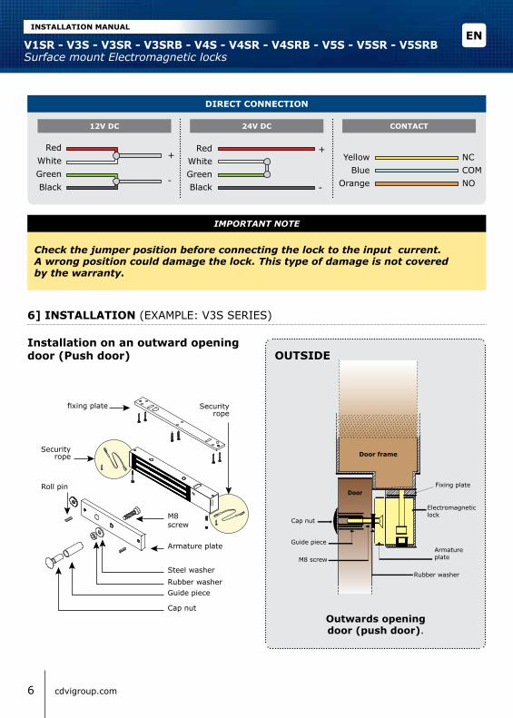
5] ElECTRICAl CONNECTIONS
The NO/NC signal only switches when the door is closed with the power to it on.
TERMINAlBlOCK CORRESPONDENCE V3S
V4S - V5SV3SR - V3SRB - V4SR
V4SRB - V5SR - V5SRB
+ 12 or 24V dc
- - 0 V
N.C NC (Normally closed) -
COM COM -
N.O NO (Normally open) -
wITH BUIlT-IN PCB BOARD
12V dcFactorySetup
12V dc 12V dc24V dc 24V dc 24V dc
Voltage selection jumpers Voltage selection jumpers Voltage selection jumpers
4] OPTIONAl ACCESSORIES
References l3l4l5 Z3Z4Z5 UBKU UBKP AMA3AMA5 DPM300DPM500 lZ1
Description L-shaped bracketfor lock
Z-shaped bracketfor lock
Armature basefor glass door
Universal basefor glass door Armature base Door position
monitoring
L & Z-shaped bracket
for 180kg lock
V3S - V4S - V5S V3SR - V4SR - V5SR V3SRB - V4SRB - V5SRB
-+
Surfacemount
magneticlock
Armatureplate
Fixingplate
Roll pin5x16
Steelwasher
4x25woodscrew
Key3mm
Key5mm
1 1 1 2 2 7 1 1
M8x35screw
M8x25screw
3x8 self-tapping
screw
Guidepiece
Capnut
Safetyrope
Rubberwasher
Installationmanual
1 1 1 1 1 2 1 1
ENV1SR - V3S - V3SR - V3SRB - V4S - V4SR - V4SRB - V5S - V5SR - V5SRBSurface mount Electromagnetic locks
INSTAllATION MANUAl
5cdvigroup.com
Securityrope
6] INSTAllATION (EXAMPLE: V3S SERIES)
DIRECT CONNECTION
12V DC 24V DC CONTACT
Red RedYellow NC
Blue COMOrange NO
++
White White
--
Green GreenBlack Black
fixing plate Securityrope
Securityrope
Armature plate
M8 screw
Cap nut
Guide pieceRubber washer
Roll pin
Steel washerRubber washer
Fixing plate
Door frame
Outwards openingdoor (push door).
Electromagneticlock
Armature plate
Cap nut
Guide piece
M8 screw
Outside
Door
Installation on an outward opening door (Push door)
Check the jumper position before connecting the lock to the input current.A wrong position could damage the lock. This type of damage is not coveredby the warranty.
IMPORTANT NOTE
ENV1SR - V3S - V3SR - V3SRB - V4S - V4SR - V4SRB - V5S - V5SR - V5SRBSurface mount Electromagnetic locks
INSTAllATION MANUAl
6 cdvigroup.com
Electromagnetic lockArmature plate
Adjustable
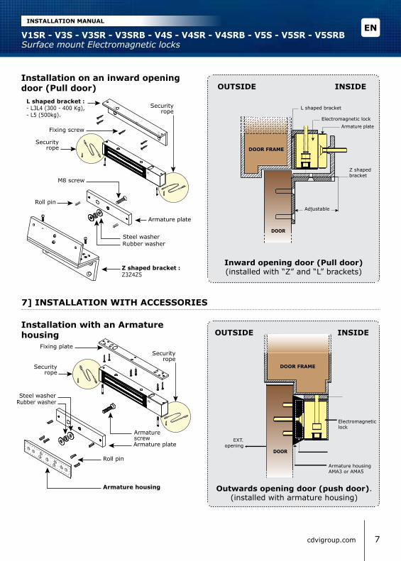
Inward opening door (Pull door) (installed with “Z” and “L” brackets)Z shaped bracket :
Z3Z4Z5
l shaped bracket :- L3L4 (300 - 400 Kg),- L5 (500kg).
L shaped bracket
Z shaped bracket
Installation on an inward openingdoor (Pull door)
Fixing screw
Rubber washer
Roll pin
Steel washer
Armature plate
M8 screw
DOOR FRAME
Outside inside
DOOR
7] INSTAllATION wITH ACCESSORIES
Fixing plate
Securityrope
Securityrope
Securityrope
Securityrope
Armature housing
Armature plate
Rubber washer
Roll pin
Steel washer
Armature screw
Outwards opening door (push door).(installed with armature housing)
Outside insideInstallation with an Armaturehousing
Armature housing AMA3 or AMA5
DOOR FRAME
Electromagnetic lock
DOOR
EXT. opening
ENV1SR - V3S - V3SR - V3SRB - V4S - V4SR - V4SRB - V5S - V5SR - V5SRBSurface mount Electromagnetic locks
INSTAllATION MANUAl
7cdvigroup.com

Fixing plateSecurity
ropeSecurity
rope
Armature housing for glass door UBKU
Rubber washer
Roll pin
Steel washer
Armaturescrew
Outward opening door (Push door) (installed with UBKU brackets)
Installation with base for glass doorOutside inside
DOOR FRAME
Electromagnetic lock
Universal base for glassdoor UBKUDOOR
Fixing plate
Armature plate
DOOR
GlASSFRAME
Adjustable
UBKP
Inward opening door (Pull door) (installed with “UBKP”, “L3L4L5”
and Z3Z4Z5 brackets)
Installation with basefor glass door
Universalhousing forglass doorUBKP
Rubber washer
Steel washer
Armatureplate
Armaturescrew
Securityrope
Securityrope
Roll pin
Outside inside
Z shaped bracketZ3Z4Z5
l shaped bracket :- L3L4 (300 - 400 Kg),- L5 (500kg).
ENV1SR - V3S - V3SR - V3SRB - V4S - V4SR - V4SRB - V5S - V5SR - V5SRBSurface mount Electromagnetic locks
INSTAllATION MANUAl
8 cdvigroup.com
8] FAUlT FINDING
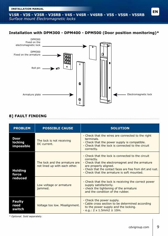
Installation with DPM300 - DPM400 - DPM500 (Door position monitoring)*
Roll pin
Armature plate Electromagnetic lock
DPM300Fixed on the armature
DPM300Fixed on the
electromagnetic lock
PROBlEM POSSIBlE CAUSE SOlUTION
Door locking impossible
The lock is not receiving DC current.
- Check that the wires are connected to the right terminals.- Check that the power supply is compatible.- Check that the lock is connected to the circuit correctly.
Holding force reduced
The lock and the armature are not lined up with each other.
- Check that the lock is connected to the circuit correctly.- Check that the electromagnet and the armature are properly aligned. - Check that the contact faces are free from dirt and rust.- Check that the armature is soft mounted.
Low voltage or armature jammed.
- Check that the lock is receiving the correct power supply satisfactorily.- check the tightening of the armature and the condition of the rubber.
Faulty reed switch
Voltage too low. Misalignment.
- Check the power supply.- Cable cross section to be determined according to the power supply and the locking.- e.g.: 2 x 1.5mm2 ≥ 10m.
* Optional. Sold separately.
ENV1SR - V3S - V3SR - V3SRB - V4S - V4SR - V4SRB - V5S - V5SR - V5SRBSurface mount Electromagnetic locks
INSTAllATION MANUAl
9cdvigroup.com

9] NOTES
ENV1SR - V3S - V3SR - V3SRB - V4S - V4SR - V4SRB - V5S - V5SR - V5SRBSurface mount Electromagnetic locks
INSTAllATION MANUAl
10 cdvigroup.com

1] PRESENTACIÓN DE PRODUCTO
La gama de ventosas con señalización
visual y sonora, en sus versiones de
300, 400 y 500 kg, cumple con la
normativa vigente para personas de
movilidad reducida.
Muchas gracias por su confianza en CDVI con la adquisición de este producto.
Montaje en superficie*. 1 relé*. Monitorización*. Señalización luminosa y sonora*. Fuerza de retención: 180, 300, 400
o 500 kg*. Conforme a norma NFS 61-937. Incluye cables de seguridad*. Alta resistencia a la corrosión. Incluye contraplaca. Sin elementos mecánicos. Instalación muy sencilla. Recomendado para instalar en interior. Funcionamiento invertido: La puerta
queda desbloqueada en cuanto se corta la corriente. Sin magnetismo residual. Varistor integrado: Protección electrónica
para eliminar EMF. Dimensiones de ventosas (Alto x Ancho x Prof.):
- V1SR = 167 x 34 x 21 mm. - Gama V3S = 254 x 45 x 27 mm. - Gama V4S = 254 x 50 x 27 mm. - Gama V5S = 272 x 66 x 40 mm. Dimensiones de contraplacas (A x A x P):
- 180 kg = 130 x 32 x 9 mm. - 300 kg = 185 x 38 x 11 mm. - 400 kg = 185 x 45 x 12 mm. - 500 kg = 185 x 60 x 12 mm. Funcionamiento silencioso. Alimentación: 12/24 Vdc. Consumo:
- 12 Vdc = 500 mA. - 24 Vdc = 250 mA.
Ref. Fuerza de retención lED Zum-
bador Relé Monit.
V1SR 180 kg - - -
V3S 300 kg - - -
V3SR 300 kg -
V3SRB 300 kg
V4S 400 kg - - -
V4SR 400 kg -
V4SRB 400 kg
V5S 500 kg - - -
V5SR 500 kg -
V5SRB 500 kg
Certificado CE
DEEE
IP42
CÓDIGO DE COlORES
AZUl VENTOSA ALIMENTADA
ROJO BLOQUEADA VERDE DESBLOQUEADA
AZUl BLOQUEADA VERDE DESB. + ZUMBADOR
RoHS ARD212 BS60
Fuentes de alimentación
recomendadas
* Según versión.
ESV1SR - V3S - V3SR - V3SRB - V4S - V4SR - V4SRB - V5S - V5SR - V5SRBVentosas electromagnéticas de superficie
MANUAl DE INSTAlACIÓN
11cdvigroup.com

2] NOTAS y RECOMENDACIONES
AlIMENTACIÓNUna ventosa se alimenta siempre con corriente continua, y a muy baja tensión para una mayor seguridad. Se recomienda utilizar fuentes de alimentación CDVI para las ventosas Diax®; sin embargo, se pueden usar fuentes de otras marcas, con la condición de que presenten unas características equivalentes, y además estén filtradas, reguladas, rectificadas. Deberán contar también con protección mediante fusible en los cir-cuitos primario y secundario.
CONSEJOS DE INSTAlACIÓN- Defina el nivel de seguridad del acceso.- Adapte la fuerza de retención máxima de acuerdo a ese nivel de seguridad.- Seleccione la ventosa Diax® en función del entorno, si irá en exterior o en interior, condiciones climáticas, etc. (Por ejemplo, use una ventosa de acero inoxidable para instalar en exterior).- Instale siempre la ventosa en el interior del acceso a asegurar.- Asegúrese de que la instalación permita que el marco de la puerta y la hoja, así como la propia ventosa, contraplaca y sus accesorios, puedan resistir el paso del tiempo y el uso continuado. - Adapte los accesorios de montaje en función de las características del lugar de instalación de la ventosa y la contraplaca (tipo de tornillería, accesorios, etc.).- Defina correctamente el paso del cableado para evitar actos vandálicos y condiciones adversas del entorno (sírvase de usar pasacables, prensaestopas, tubos flexibles, etc.).
Los cables de seguridadLa ventosa está sometida a lo largo de su vida útil a sucesivos golpes, a tensiones en los puntos de fijación y a intentos de apertura y vandalismo. Todo ello puede hacer que la ventosa acabe por despren-derse del marco.A fin de evitar que esto ocurra instale los dos cables de seguridad según se indica en el esquema adjunto.
La contraplaca- Es primordial fijar correctamente la ventosa y la contraplaca a sus soportes.- Asegúrese de que las superficies magnetizadas de la ventosa y la contraplaca están en contacto.- La contraplaca debe poder pivotar un poco, a fin de poder corregir posibles desalineaciones a la hora de instalar.
Cable de seguridad(se fija a la ventosa y al marco)
Cable de seguridad(se fija a la ventosa y al marco)
La función de una ventosa electromagnética es la de asegurar y mantener bloqueado un acceso. Este docu-mento es un manual de instalación y puesta en marcha que permitirá asegurar el acceso en función de las características del producto, del lugar de instalación y de las condiciones del entorno.
NORMATIVA DE INCENDIO EN PUERTAS DE EMERGENCIAEn el caso de instalar la ventosa en una puerta de emergencia, es obligatorio asegurarse de que el ac-ceso quedará libre en el caso de declararse una alarma de incendio para permitir una adecuada eva-cuación. Las ventosas instaladas deben estar siempre conforme a la normativa local anti-incendio (Por ejemplo, en Francia la norma NF S 61-937).Para más información, contacte con CDVI, los responsables anti-incendio locales o los reponsables de seguridad del lugar de instalación.
ESV1SR - V3S - V3SR - V3SRB - V4S - V4SR - V4SRB - V5S - V5SR - V5SRBVentosas electromagnéticas de superficie
MANUAl DE INSTAlACIÓN
12 cdvigroup.com
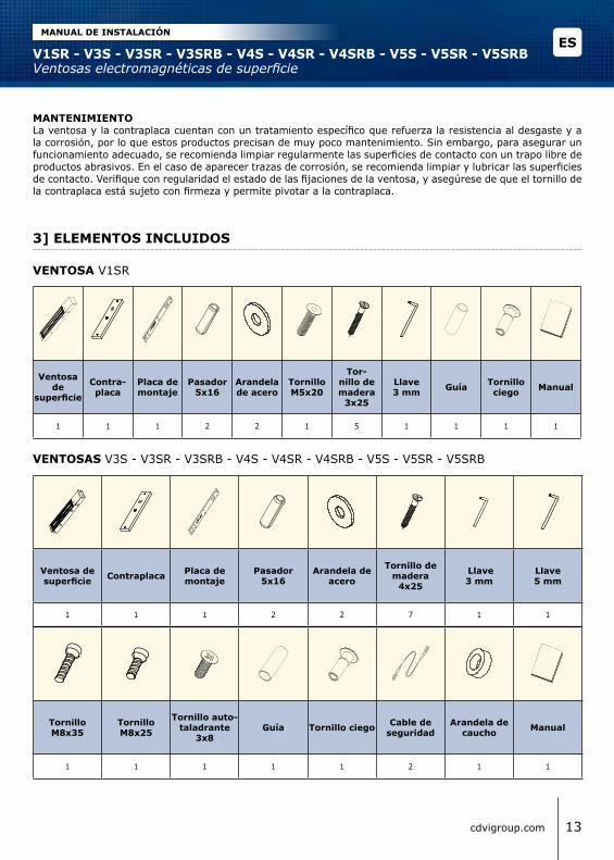
3] ElEMENTOS INClUIDOS
Ventosa de superficie Contraplaca Placa de
montajePasador
5x16Arandela de
acero
Tornillo de madera
4x25
llave3 mm
llave5 mm
1 1 1 2 2 7 1 1
Tornillo M8x35
TornilloM8x25
Tornillo auto-taladrante
3x8Guía Tornillo ciego Cable de
seguridadArandela de
caucho Manual
1 1 1 1 1 2 1 1
Ventosa de
superficie
Contra-placa
Placa de montaje
Pasador5x16
Arandela de acero
TornilloM5x20
Tor-nillo de madera
3x25
llave3 mm Guía Tornillo
ciego Manual
1 1 1 2 2 1 5 1 1 1 1
VENTOSA V1SR
VENTOSAS V3S - V3SR - V3SRB - V4S - V4SR - V4SRB - V5S - V5SR - V5SRB
MANTENIMIENTOLa ventosa y la contraplaca cuentan con un tratamiento específico que refuerza la resistencia al desgaste y a la corrosión, por lo que estos productos precisan de muy poco mantenimiento. Sin embargo, para asegurar un funcionamiento adecuado, se recomienda limpiar regularmente las superficies de contacto con un trapo libre de productos abrasivos. En el caso de aparecer trazas de corrosión, se recomienda limpiar y lubricar las superficies de contacto. Verifique con regularidad el estado de las fijaciones de la ventosa, y asegúrese de que el tornillo de la contraplaca está sujeto con firmeza y permite pivotar a la contraplaca.
ESV1SR - V3S - V3SR - V3SRB - V4S - V4SR - V4SRB - V5S - V5SR - V5SRBVentosas electromagnéticas de superficie
MANUAl DE INSTAlACIÓN
13cdvigroup.com

Cable de seguridad
5] ESQUEMA DE CABlEADO
La señal NO/NC no conmuta salvo que la puerta esté bloqueada y con tensión.
BORNE CORRESPONDENCIA V3SV4S - V5S
V3SR - V3SRB - V4SRV4SRB - V5SR - V5SRB
+ 12 o 24 Vdc
- - 0 V
N.C NC (Normalmente cerrado) -
COM COM (Común) -
N.O NO (Normalmente abierto) -
ElECTRÓNICA DE CONTROl INTEGRADA
12 Vdcpor
defecto
12 Vdc 12 Vdc 12 Vdc24 Vdc 24 Vdc 24 Vdc
Jumpers de selección de voltaje Jumpers de selección de voltaje Jumpers de selección de voltaje
4] ACCESORIOS OPCIONAlES
Referencias l3l4 (300KG)l5 (500KG) Z3Z4Z5 UBKU UBKP AMA3 (300KG)
AMA5 (500KG)DPM300DPM500 lZ1
DescripciónSoporte en “L”para ventosa
(300,400 y 500 kg)
Soporte en “Z”para ventosa
(300,400 y 500 kg)
Soporte decontraplaca parapuerta de vidrio
(300,400 y 500 kg)
Soporte universal para puerta de
vidrio(300,400 y 500 kg)
Soporte de contraplaca para
puertas cortafuego
(300 y 500 kg)
Contactode posiciónde puerta
(300 y 500 kg)
Kit de soportes en “L” y “Z”
para V1SR(180 kg)
V3S - V4S - V5S V3SR - V4SR - V5SR V3SRB - V4SRB - V5SRB
-+
ESV1SR - V3S - V3SR - V3SRB - V4S - V4SR - V4SRB - V5S - V5SR - V5SRBVentosas electromagnéticas de superficie
MANUAl DE INSTAlACIÓN
14 cdvigroup.com
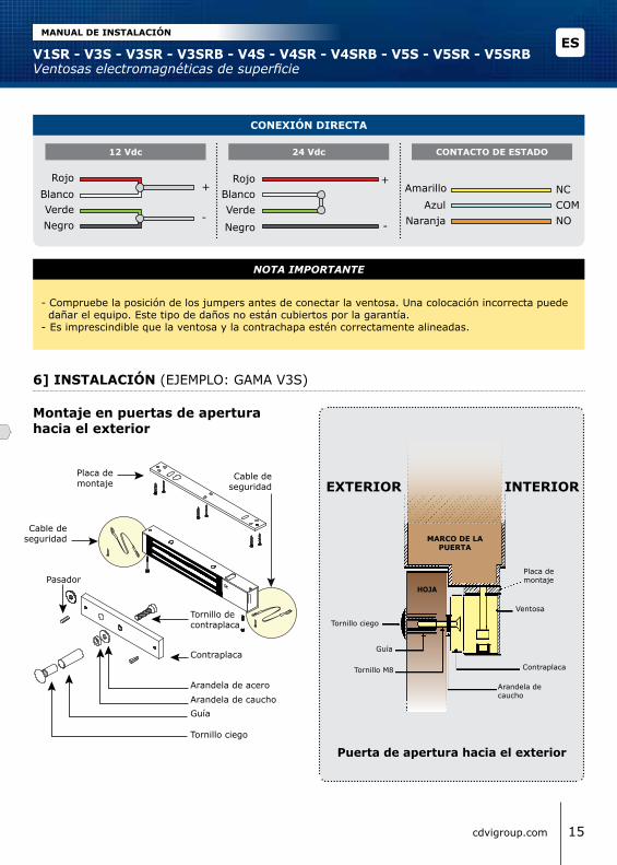
- Compruebe la posición de los jumpers antes de conectar la ventosa. Una colocación incorrecta puede dañar el equipo. Este tipo de daños no están cubiertos por la garantía.- Es imprescindible que la ventosa y la contrachapa estén correctamente alineadas.
NOTA IMPORTANTE
6] INSTAlACIÓN (EJEMPLO: GAMA V3S)
CONExIÓN DIRECTA
12 Vdc 24 Vdc CONTACTO DE ESTADO
Rojo RojoAmarillo NC
Azul COMNaranja NO
+Blanco Blanco
--
Verde VerdeNegro
Placa de montaje
Cable de seguridad
Cable de seguridad
Contraplaca
Tornillo decontraplaca
Tornillo ciego
GuíaArandela de caucho
Pasador
Arandela de acero Arandela de caucho
Placa de montaje
MARCO DE lA PUERTA
Puerta de apertura hacia el exterior
Ventosa
Contraplaca
Tornillo ciego
Guía
Tornillo M8
exterior interior
HOJA
Montaje en puertas de apertura hacia el exterior
ESV1SR - V3S - V3SR - V3SRB - V4S - V4SR - V4SRB - V5S - V5SR - V5SRBVentosas electromagnéticas de superficie
MANUAl DE INSTAlACIÓN
15cdvigroup.com
Negro
+

Cable de seguridad
Cable de seguridad
VentosaContraplaca
Regulable
Puerta de apertura hacia el interior(instalación con perfiles en “L” y en “Z”).Perfil en “Z”
Z3Z4Z5
Perfil en “L”
Perfil en “Z”
Montaje en puertas de apertura hacia el interior
MARCO DE lA PUERTA
EXTERIOR INTERIOR
HOJA
7] INSTAlACIÓN CON ACCESORIOS (EJEMPLO: GAMA V3S)
Placa de montaje
Soporte de contraplacaAMA3 - AMA5
Contraplaca
Arandela de caucho
Pasadores
Arandela de acero
Tornillo decontraplaca
Puerta de apertura hacia el exterior
EXTERIOR INTERIOR
Instalación en puertas cortafuego (usando soportes AMA)
Soporte de contraplaca AMA3 o AMA5
Placa de montaje
MARCO DE lA PUERTA
Ventosa
ContraplacaHOJA
Sentido de pertura
ESV1SR - V3S - V3SR - V3SRB - V4S - V4SR - V4SRB - V5S - V5SR - V5SRBVentosas electromagnéticas de superficie
MANUAl DE INSTAlACIÓN
16 cdvigroup.com
Cable de seguridad
Cable de seguridad
Perfil en “L”- L3L4 (300 - 400 Kg)- L5 (500 kg).
Tornillo de fijación
Arandela de caucho
Pasador
Arandela de acero
Contraplaca
Tornillo M8
Placa de montaje
Contraplaca
Soporte de contraplaca para puerta de vidrio UBKU
Arandela de caucho
Pasador
Arandela de acero
Tornillo de contraplaca
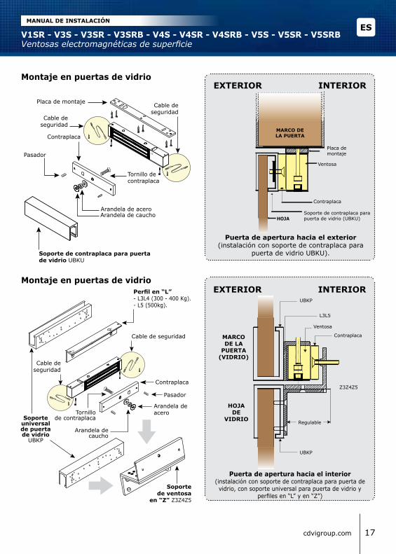
Puerta de apertura hacia el exterior (instalación con soporte de contraplaca para
puerta de vidrio UBKU).
Montaje en puertas de vidrioExtErior interior
MARCO DE lA PUERTA
Ventosa
Contraplaca
Soporte de contraplaca para puerta de vidrio (UBKU)HOJA
Placa de montaje
Ventosa
Z3Z4Z5
L3L5
Contraplaca
HOJA DE
VIDRIO
MARCO DE lA
PUERTA (VIDRIO)
Regulable
Puerta de apertura hacia el interior(instalación con soporte de contraplaca para puerta de vidrio, con soporte universal para puerta de vidrio y
perfiles en “L” y en “Z”)
Montaje en puertas de vidrio
Soporte universal de puerta de vidrio
UBKP
UBKP
Arandela de caucho
Arandela de acero
Contraplaca
Tornillo de contraplaca
Pasador
exterior interior
Soporte de ventosa
en “Z” Z3Z4Z5
Perfil en “L”- L3L4 (300 - 400 Kg).- L5 (500kg).
Cable de seguridad
Cable de seguridad
Cable de seguridad
Cable de seguridad
ESV1SR - V3S - V3SR - V3SRB - V4S - V4SR - V4SRB - V5S - V5SR - V5SRBVentosas electromagnéticas de superficie
MANUAl DE INSTAlACIÓN
17cdvigroup.com
UBKP
8] SOlUCIÓN DE PROBlEMAS
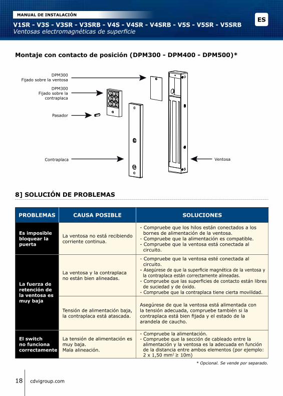
Montaje con contacto de posición (DPM300 - DPM400 - DPM500)*
Pasador
Contraplaca Ventosa
DPM300Fijado sobre la
contraplaca
DPM300Fijado sobre la ventosa
PROBlEMAS CAUSA POSIBlE SOlUCIONES
Es imposible bloquear la puerta
La ventosa no está recibiendo corriente continua.
- Compruebe que los hilos están conectados a los bornes de alimentación de la ventosa.- Compruebe que la alimentación es compatible.- Compruebe que la ventosa está conectada al circuito.
la fuerza de retención de la ventosa es muy baja
La ventosa y la contraplaca no están bien alineadas.
- Compruebe que la ventosa esté conectada al circuito.- Asegúrese de que la superficie magnética de la ventosa y la contraplaca están correctamente alineadas. - Compruebe que las superficies de contacto están libres de suciedad y de óxido.- Compruebe que la contraplaca tiene cierta movilidad.
Tensión de alimentación baja, la contraplaca está atascada.
Asegúrese de que la ventosa está alimentada con la tensión adecuada, compruebe también si la contraplaca está bien fijada y el estado de la arandela de caucho.
El switch no funciona correctamente
La tensión de alimentación es muy baja.Mala alineación.
- Compruebe la alimentación.- Compruebe que la sección de cableado entre la alimentación y la ventosa es la adecuada en función de la distancia entre ambos elementos (por ejemplo: 2 x 1,50 mm2 ≥ 10m)
* Opcional. Se vende por separado.
ESV1SR - V3S - V3SR - V3SRB - V4S - V4SR - V4SRB - V5S - V5SR - V5SRBVentosas electromagnéticas de superficie
MANUAl DE INSTAlACIÓN
18 cdvigroup.com

9] NOTAS
ESV1SR - V3S - V3SR - V3SRB - V4S - V4SR - V4SRB - V5S - V5SR - V5SRBVentosas electromagnéticas de superficie
MANUAl DE INSTAlACIÓN
19cdvigroup.com
The installer’s choice cdvigroup.com
Referencia :G0301ES0341V01 Extranet : EXE-CDVI_IM VENTOSAS DE SUPERFICIE CMYK A5 EN-ES 01
All
the
info
rmat
ion
cont
aine
d w
ithin
thi
s do
cum
ent
(pic
ture
s, d
raw
ing,
fea
ture
s, s
peci
ficat
ions
and
dim
ensi
ons)
coul
d be
per
cept
ibly
diff
eren
t an
d ca
n be
cha
nged
with
out
prio
r no
tice.
Toda
la in
form
ació
n m
ostr
ada
en e
ste
docu
men
to (
dibu
jos,
dia
gram
as,
espe
cific
acio
nes,
car
acte
ríst
icas
y d
imen
sion
es)
son
a tít
ulo
info
rmat
ivo
y pu
eden
dife
rir
del p
rodu
cto
final
, de
l mis
mo
mod
o qu
e so
n su
scep
tible
s de
suf
rir
mod
ifica
cion
es
sin
notifi
caci
ón p
revi
a.
*G0301ES0341V01*
CDVI GroupFRANCE (Headquarter/Siège social)
Phone: +33 (0)1 48 91 01 02Fax: +33 (0)1 48 91 21 21
CDVIFRANCE + EXPORTPhone: +33 (0)1 48 91 01 02Fax: +33 (0)1 48 91 21 21
CDVI AMERICAS[CANADA - USA]
Phone: +1 (450) 682 7945Fax: +1 (450) 682 9590 CDVI BENELUX[BELGIUM - NETHERLAND - LUXEMBOURG]
Phone: +32 (0) 56 73 93 00Fax: +32 (0) 56 73 93 05
CDVITAIWANPhone: +886 (0)42471 2188Fax: +886 (0)42471 2131
CDVISUISSEPhone: +41 (0)21 882 18 41Fax: +41 (0)21 882 18 42
CDVICHINA Phone: +86 (0)10 62414516Fax: +86 (0)10 62414519
CDVI IBÉRICA[SPAIN - PORTUGAL]
Phone: +34 (0)935 390 966Fax: +34 (0)935 390 970
CDVIITALIAPhone: +39 0331 97 38 08 Fax: +39 0331 97 39 70
CDVIMAROCPhone: +212 (0)5 22 48 09 40Fax: +212 (0)5 22 48 34 69
CDVI SWEDEN [SWEDEN - DENMARK - NORWAY - FINLAND]
Phone: +46 (0)31 760 19 30Fax: +46 (0)31 748 09 30 CDVI UK [UNITED KINGDOM - IRELAND]
Phone: +44 (0)1628 531300 Fax: +44 (0)1628 531003