v-twin - made in barnoldswick, england · installation steps personal settings break in period and...
TRANSCRIPT
www.hopetech.com
HYDRAULIC DISC BRAKE SYSTEMMODEL YEAR 2012
INTRODUCTIONWARNING PLEASE READ FIRST
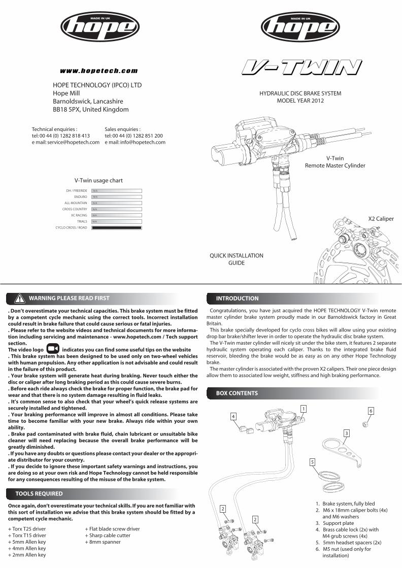
1. Brake system, fully bled2. M6 x 18mm caliper bolts (4x) and M6 washers3. Support plate4. Brass cable lock (2x) with M4 grub screws (4x)5. 5mm headset spacers (2x)6. M5 nut (used only for installation)
1
3
6
QUICK INSTALLATIONGUIDE
BOX CONTENTS
2
4
2
Technical enquiries : Sales enquiries :tel: 00 44 (0) 1282 818 413 tel: 00 44 (0) 1282 851 200e mail: [email protected] e mail: [email protected]
TOOLS REQUIRED
+ Torx T25 driver+ Torx T15 driver+ 5mm Allen key+ 4mm Allen key+ 2mm Allen key
+ Flat blade screw driver+ Sharp cable cutter+ 8mm spanner
Once again, don’t overestimate your technical skills. If you are not familiar with this sort of installation we advise that this brake system should be fitted by a competent cycle mechanic.
Congratulations, you have just acquired the HOPE TECHNOLOGY V-Twin remote master cylinder brake system proudly made in our Barnoldswick factory in Great Britain.
This brake specially developed for cyclo cross bikes will allow using your existing drop bar brake/shifter lever in order to operate the hydraulic disc brake system.
The V-Twin master cylinder will nicely sit under the bike stem, it features 2 separate hydraulic system operating each caliper. Thanks to the integrated brake fluid reservoir, bleeding the brake would be as easy as on any other Hope Technology brake.
The master cylinder is associated with the proven X2 calipers. Their one piece design allow them to associated low weight, stiffness and high braking performance.
HOPE TECHNOLOGY (IPCO) LTDHope MillBarnoldswick, LancashireBB18 5PX, United Kingdom
. Don’t overestimate your technical capacities. This brake system must be fitted by a competent cycle mechanic using the correct tools. Incorrect installation could result in brake failure that could cause serious or fatal injuries.. Please refer to the website videos and technical documents for more informa-tion including servicing and maintenance - www.hopetech.com / Tech support section.The video logo indicates you can find some useful tips on the website. This brake system has been designed to be used only on two-wheel vehicles with human propulsion. Any other application is not advisable and could result in the failure of this product.. Your brake system will generate heat during braking. Never touch either the disc or caliper after long braking period as this could cause severe burns.. Before each ride always check the brake for proper function, the brake pad for wear and that there is no system damage resulting in fluid leaks.. It’s common sense to also check that your wheel’s quick release systems are securely installed and tightened.. Your braking performance will improve in almost all conditions. Please take time to become familiar with your new brake. Always ride within your own ability.. Brake pad contaminated with brake fluid, chain lubricant or unsuitable bike cleaner will need replacing because the overall brake performance will be greatly diminished.. If you have any doubts or questions please contact your dealer or the appropri-ate distributor for your country.. If you decide to ignore these important safety warnings and instructions, you are doing so at your own risk and Hope Technology cannot be held responsible for any consequences resulting of the misuse of the brake system.
X2 Caliper
V-TwinRemote Master Cylinder
V-Twin usage chart
DH / FREERIDE
ALL MOUNTAIN
XC RACING
CROSS COUNTRY
ENDURO
TRIALS
CYCLO CROSS / ROAD
N/A
N/A
N/A
N/A
N/A
N/A
V-TWIN
5
INSTALLATION STEPS
PERSONAL SETTINGS
BREAK IN PERIOD AND MAINTENANCE
2. ATTACHING THE DISC TO THE HUB
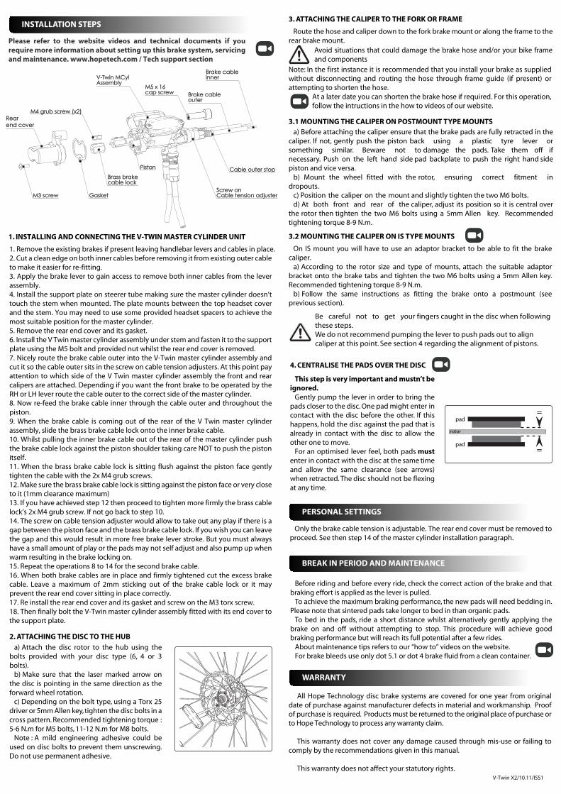
1. INSTALLING AND CONNECTING THE V-TWIN MASTER CYLINDER UNIT
3. ATTACHING THE CALIPER TO THE FORK OR FRAME
4. CENTRALISE THE PADS OVER THE DISC
V-Twin X2/10.11/ISS1
3.2 MOUNTING THE CALIPER ON IS TYPE MOUNTS
=
=
pad
pad
rotor
WARRANTY
All Hope Technology disc brake systems are covered for one year from original date of purchase against manufacturer defects in material and workmanship. Proof of purchase is required. Products must be returned to the original place of purchase or to Hope Technology to process any warranty claim.
This warranty does not cover any damage caused through mis-use or failing to comply by the recommendations given in this manual.
This warranty does not affect your statutory rights.
3.1 MOUNTING THE CALIPER ON POSTMOUNT TYPE MOUNTSa) Before attaching the caliper ensure that the brake pads are fully retracted in the
caliper. If not, gently push the piston back using a plastic tyre lever or something similar. Beware not to damage the pads. Take them off if necessary. Push on the left hand side pad backplate to push the right hand side piston and vice versa.
b) Mount the wheel fitted with the rotor, ensuring correct fitment in dropouts.
c) Position the caliper on the mount and slightly tighten the two M6 bolts.d) At both front and rear of the caliper, adjust its position so it is central over
the rotor then tighten the two M6 bolts using a 5mm Allen key. Recommended tightening torque 8-9 N.m.
Be careful not to get your fingers caught in the disc when following these steps.We do not recommend pumping the lever to push pads out to align caliper at this point. See section 4 regarding the alignment of pistons.
a) Attach the disc rotor to the hub using the bolts provided with your disc type (6, 4 or 3 bolts).
b) Make sure that the laser marked arrow on the disc is pointing in the same direction as the forward wheel rotation.
c) Depending on the bolt type, using a Torx 25 driver or 5mm Allen key, tighten the disc bolts in a cross pattern. Recommended tightening torque : 5-6 N.m for M5 bolts, 11-12 N.m for M8 bolts.
Note : A mild engineering adhesive could be used on disc bolts to prevent them unscrewing. Do not use permanent adhesive.
1. Remove the existing brakes if present leaving handlebar levers and cables in place. 2. Cut a clean edge on both inner cables before removing it from existing outer cable to make it easier for re-fitting.3. Apply the brake lever to gain access to remove both inner cables from the lever assembly.4. Install the support plate on steerer tube making sure the master cylinder doesn’t touch the stem when mounted. The plate mounts between the top headset cover and the stem. You may need to use some provided headset spacers to achieve the most suitable position for the master cylinder.5. Remove the rear end cover and its gasket.6. Install the V Twin master cylinder assembly under stem and fasten it to the support plate using the M5 bolt and provided nut whilst the rear end cover is removed.7. Nicely route the brake cable outer into the V-Twin master cylinder assembly and cut it so the cable outer sits in the screw on cable tension adjusters. At this point pay attention to which side of the V Twin master cylinder assembly the front and rear calipers are attached. Depending if you want the front brake to be operated by the RH or LH lever route the cable outer to the correct side of the master cylinder.8. Now re-feed the brake cable inner through the cable outer and throughout the piston.9. When the brake cable is coming out of the rear of the V Twin master cylinder assembly, slide the brass brake cable lock onto the inner brake cable.10. Whilst pulling the inner brake cable out of the rear of the master cylinder push the brake cable lock against the piston shoulder taking care NOT to push the piston itself.11. When the brass brake cable lock is sitting flush against the piston face gently tighten the cable with the 2x M4 grub screws.12. Make sure the brass brake cable lock is sitting against the piston face or very close to it (1mm clearance maximum)13. If you have achieved step 12 then proceed to tighten more firmly the brass cable lock’s 2x M4 grub screw. If not go back to step 10.14. The screw on cable tension adjuster would allow to take out any play if there is a gap between the piston face and the brass brake cable lock. If you wish you can leave the gap and this would result in more free brake lever stroke. But you must always have a small amount of play or the pads may not self adjust and also pump up when warm resulting in the brake locking on.15. Repeat the operations 8 to 14 for the second brake cable.16. When both brake cables are in place and firmly tightened cut the excess brake cable. Leave a maximum of 2mm sticking out of the brake cable lock or it may prevent the rear end cover sitting in place correctly.17. Re install the rear end cover and its gasket and screw on the M3 torx screw.18. Then finally bolt the V-Twin master cylinder assembly fitted with its end cover to the support plate.
On IS mount you will have to use an adaptor bracket to be able to fit the brake caliper.
a) According to the rotor size and type of mounts, attach the suitable adaptor bracket onto the brake tabs and tighten the two M6 bolts using a 5mm Allen key. Recommended tightening torque 8-9 N.m.
b) Follow the same instructions as fitting the brake onto a postmount (see previous section).
This step is very important and mustn’t be ignored.
Gently pump the lever in order to bring the pads closer to the disc. One pad might enter in contact with the disc before the other. If this happens, hold the disc against the pad that is already in contact with the disc to allow the other one to move.
For an optimised lever feel, both pads must enter in contact with the disc at the same time and allow the same clearance (see arrows) when retracted. The disc should not be flexing at any time.
Only the brake cable tension is adjustable. The rear end cover must be removed to proceed. See then step 14 of the master cylinder installation paragraph.
Please refer to the website videos and technical documents if you require more information about setting up this brake system, servicing and maintenance. www.hopetech.com / Tech support section
Before riding and before every ride, check the correct action of the brake and that braking effort is applied as the lever is pulled.
To achieve the maximum braking performance, the new pads will need bedding in. Please note that sintered pads take longer to bed in than organic pads.
To bed in the pads, ride a short distance whilst alternatively gently applying the brake on and off without attempting to stop. This procedure will achieve good braking performance but will reach its full potential after a few rides.
About maintenance tips refers to our “how to” videos on the website.For brake bleeds use only dot 5.1 or dot 4 brake fluid from a clean container.
Avoid situations that could damage the brake hose and/or your bike frame and components
Note: In the first instance it is recommended that you install your brake as supplied without disconnecting and routing the hose through frame guide (if present) or attempting to shorten the hose.
At a later date you can shorten the brake hose if required. For this operation, follow the intructions in the how to videos of our website.
Route the hose and caliper down to the fork brake mount or along the frame to the rear brake mount.
M3 screwM3 screw GasketGasket
Brass brakeBrass brakecable lockcable lock
M4 grub screw (x2)M4 grub screw (x2)
V-Twin MCylV-Twin MCylAssemblyAssembly
Rear Rear end coverend cover
PistonPiston
Brake cableBrake cableinnerinner
Brake cableBrake cableouterouter
Cable outer stopCable outer stop
Screw onScrew onCable tension adjusterCable tension adjuster
M5 x 16M5 x 16cap screwcap screw