utra repeater radio transmission and reception (release 5)
DESCRIPTION
3rd Generation Partnership Project;Technical Specification Group Radio Access Network;UTRA repeater radio transmission and reception(Release 5)TRANSCRIPT
3GPP TS 25.106 V5.12.0 (2006-12)Technical Specification
3rd Generation Partnership Project;Technical Specification Group Radio Access Network;
UTRA repeater radio transmission and reception(Release 5)
The present document has been developed within the 3rd Generation Partnership Project (3GPP TM) and may be further elaborated for the purposes of 3GPP. The present document has not been subject to any approval process by the 3GPP Organisational Partners and shall not be implemented. This Specification is provided for future development work within 3GPP only. The Organisational Partners accept no liability for any use of this Specification.Specifications and reports for implementation of the 3GPP TM system should be obtained via the 3GPP Organisational Partners' Publications Offices.
3GPP TS 25.106 V5.12.0 (2006-12)2Release 5T
Keywords UMTS, radio, repeater
3GPP
Postal address
3GPP support office address 650 Route des Lucioles - Sophia Antipolis
Valbonne - FRANCE Tel.: +33 4 92 94 42 00 Fax: +33 4 93 65 47 16
Internet http://www.3gpp.org
Copyright Notification
No part may be reproduced except as authorized by written permission. The copyright and the foregoing restriction extend to reproduction in all media.
© 2006, 3GPP Organizational Partners (ARIB, ATIS, CCSA, ETSI, TTA, TTC).
All rights reserved.
3GPP
3GPP TS 25.106 V5.12.0 (2006-12)3Release 5T
Contents Foreword ............................................................................................................................................................5 1 Scope ........................................................................................................................................................6 2 References ................................................................................................................................................6 3 Definitions, symbols and abbreviations ...................................................................................................6 3.1 Definitions ......................................................................................................................................................... 6 3.2 (void) ................................................................................................................................................................. 7 3.3 Abbreviations..................................................................................................................................................... 7 4 General .....................................................................................................................................................7 4.1 Relationship between Minimum Requirements and Test Requirements ........................................................... 7 4.2 Regional requirements ....................................................................................................................................... 7 5 Frequency bands and channel arrangement..............................................................................................9 5.1 Frequency bands ................................................................................................................................................ 9 5.2 TX - RX frequency separation........................................................................................................................... 9 5.3 Channel arrangement ....................................................................................................................................... 10 5.3.1 Channel spacing ......................................................................................................................................... 10 5.3.2 Channel raster............................................................................................................................................. 10 5.3.3 Channel number ......................................................................................................................................... 10 6 Output power..........................................................................................................................................11 6.1 Maximum output power................................................................................................................................... 11 6.1.1 Minimum Requirements............................................................................................................................. 11 7 Frequency stability .................................................................................................................................12 7.1 Minimum requirement ..................................................................................................................................... 12 8 Out of band gain.....................................................................................................................................12 8.1 Minimum requirement ..................................................................................................................................... 12 9 Unwanted emission ................................................................................................................................13 9.1 Out of band emission ....................................................................................................................................... 13 9.1.1 Spectrum emission mask............................................................................................................................ 13 9.2 Spurious emissions .......................................................................................................................................... 15 9.2.1 General Requirements ................................................................................................................................ 15 9.2.1.1 Minimum Requirement (Category A) .................................................................................................. 15 9.2.1.2 Minimum Requirement (Category B)................................................................................................... 16 9.2.2 Protection of BS receiver in the operating band......................................................................................... 18 9.2.2.1 General ................................................................................................................................................. 18 9.2.2.2 Minimum Requirement......................................................................................................................... 18 9.2.3 Co-existence with GSM 900 ...................................................................................................................... 19 9.2.3.1 Operation in the same geographic area................................................................................................. 19 9.2.3.1.1 Minimum Requirement ................................................................................................................... 19 9.2.3.2 Co-located Repeaters and GSM 900 base stations ............................................................................... 19 9.2.3.2.1 Minimum Requirement ................................................................................................................... 19 9.2.4 Co-existence with DCS 1800 ..................................................................................................................... 19 9.2.4.1 Operation in the same geographic area................................................................................................. 19 9.2.4.1.1 Minimum Requirement ................................................................................................................... 19 9.2.4.2 Co-located Repeaters and DCS 1800 base stations .............................................................................. 20 9.2.4.2.1 Minimum Requirement ................................................................................................................... 20 9.2.5 Co-existence with PHS .............................................................................................................................. 20 9.2.5.1 Minimum Requirement......................................................................................................................... 20 9.2.6 Co-existence with UTRA-TDD ................................................................................................................. 20 9.2.6.1 Operation in the same geographic area................................................................................................. 20 9.2.6.1.1 Minimum Requirement ................................................................................................................... 21 9.2.6.2 Co-located Repeaters and UTRA-TDD base stations........................................................................... 21 9.2.6.2.1 Minimum Requirement ................................................................................................................... 21
3GPP
3GPP TS 25.106 V5.12.0 (2006-12)4Release 5T
9.2.7 Co-existence with services in adjacent frequency bands............................................................................ 22 9.2.7.1 Minimum requirement.......................................................................................................................... 22 9.2.8 Co-existence with UTRA FDD in frequency band I .................................................................................. 22 9.2.8.1 Operation in the same geographic area................................................................................................. 22 9.2.8.1.1 Minimum Requirement ................................................................................................................... 23 9.2.8.2 Co-located Repeater and UTRA FDD BS operating in frequency band I ............................................ 23 9.2.8.2.1 Minimum Requirement ................................................................................................................... 23 9.2.9 Co-existence with UTRA FDD in frequency band III ............................................................................... 23 9.2.9.1 Operation in the same geographic area................................................................................................. 23 9.2.9.1.1 Minimum Requirement ................................................................................................................... 24 9.2.9.2 Co-located Repeater and UTRA FDD BS operating in frequency band III.......................................... 24 9.2.9.2.1 Minimum Requirement ................................................................................................................... 24 9.2.10 Co-existence with PCS1900....................................................................................................................... 24 9.2.10.1 Operation in the same geographic area................................................................................................. 24 9.2.10.1.1 Minimum Requirement ................................................................................................................... 24 9.2.10.2 Co-located Repeater and PCS1900 BS................................................................................................. 25 9.2.10.2.1 Minimum Requirement ................................................................................................................... 25 9.2.11 Co-existence with GSM850 ....................................................................................................................... 25 9.2.11.1 Operation in the same geographic area................................................................................................. 25 9.2.11.1.1 Minimum Requirement ................................................................................................................... 25 9.2.11.2 Co-located Repeater and GSM850 BS ................................................................................................. 25 9.2.11.2.1 Minimum Requirement ................................................................................................................... 25 10 Modulation accuracy ..............................................................................................................................26 10.1 Error Vector Magnitude................................................................................................................................... 26 10.1.1 Minimum requirement ............................................................................................................................... 26 10.2 Peak code domain error ................................................................................................................................... 26 10.2.1 Minimum requirement ............................................................................................................................... 26 11 Input Intermodulation.............................................................................................................................26 11.1 General Requirement ....................................................................................................................................... 26 11.1.1 Minimum requirement ............................................................................................................................... 26 11.2 Co-location with BS in other systems.............................................................................................................. 27 11.2.1 Minimum requirements .............................................................................................................................. 27 11.2.2 Minimum Requirement - Co-location with UTRA-TDD........................................................................... 28 11.3 Co-existence with other systems...................................................................................................................... 28 11.3.1 Minimum requirements .............................................................................................................................. 29 12 Output intermodulation.................................................................................................................................... 29 12.1 Minimum requirement ............................................................................................................................... 30 13 Adjacent Channel Rejection Ratio (ACRR)...........................................................................................30 13.1 Definitions and applicability............................................................................................................................ 30 13.2 Minimum Requirements .................................................................................................................................. 30
Annex A (informative): Change History ..............................................................................................31
3GPP
3GPP TS 25.106 V5.12.0 (2006-12)5Release 5T
Foreword This Technical Specification has been produced by the 3rd Generation Partnership Project (3GPP).
The contents of the present document are subject to continuing work within the TSG and may change following formal TSG approval. Should the TSG modify the contents of the present document, it will be re-released by the TSG with an identifying change of release date and an increase in version number as follows:
Version x.y.z
where:
x the first digit:
1 presented to TSG for information;
2 presented to TSG for approval;
3 or greater indicates TSG approved document under change control.
y the second digit is incremented for all changes of substance, i.e. technical enhancements, corrections, updates, etc.
z the third digit is incremented when editorial only changes have been incorporated in the document..
3GPP

3GPP TS 25.106 V5.12.0 (2006-12)6Release 5T
1 Scope The present document establishes the minimum radio frequency performance of UTRA repeaters.
2 References The following documents contain provisions which, through reference in this text, constitute provisions of the present document.
• References are either specific (identified by date of publication, edition number, version number, etc.) or non-specific.
• For a specific reference, subsequent revisions do not apply.
• For a non-specific reference, the latest version applies. In the case of a reference to a 3GPP document (including a GSM document), a non-specific reference implicitly refers to the latest version of that document in the same Release as the present document.
[1] ITU-R Recommendation SM.329: "Unwanted emissions in the spurious domain ".
[2] 3GPP TS 25.143: "UTRA Repeater Conformance Testing".
[3] 3GPP TS 25.113: "Base Station and Repeater Electromagnetic Compatibility".
[4] ETSI ETR 273-1-2: "Electromagnetic compatibility and Radio spectrum Matters (ERM); Improvement of radiated methods of measurement (using test sites) and evaluation of the corresponding measurement uncertainties; Part 1: Uncertainties in the measurement of mobile radio equipment characteristics; Sub-part 2: Examples and annexes".
[5] 3GPP TR 25.942 "RF System Scenarios".
3 Definitions, symbols and abbreviations
3.1 Definitions For the purposes of the present document, the following terms and definitions apply:
Donor coupling loss: is the coupling loss between the repeater and the donor base station.
Down-link: Signal path where base station transmits and mobile receives.
Pass band: The repeater can have one or several pass bands. The pass band is the frequency range that the repeater operates in with operational configuration. This frequency range can correspond to one or several consecutive nominal 5 MHz channels. If they are not consecutive each subset of channels shall be considered as an individual pass band.
Repeater: A device that receives, amplifies and transmits the radiated or conducted RF carrier both in the down-link direction (from the base station to the mobile area) and in the up-link direction (from the mobile to the base station)
Up-link: Signal path where mobile transmits and base station receives.
3GPP
3GPP TS 25.106 V5.12.0 (2006-12)7Release 5T
3.2 (void)
3.3 Abbreviations For the purposes of the present document, the following abbreviations apply:
EVM Error Vector Magnitude FDD Frequency Division Duplex FFS For Further Study IMT2000 International Mobile Telecommunication-2000 ITU International Telecommunication Union RF Radio Frequency UARFCN UTRA Absolute Radio Frequency Channel Number UMTS Universal Mobile Telecommunication System UTRA Universal Terrestrial Radio Access WCDMA Wide band Code Division Multiple Access
4 General This specification applies only to UTRA-FDD repeaters.
Unless otherwise stated, all requirements in this specification apply to both the up-link and down-link directions.
4.1 Relationship between Minimum Requirements and Test Requirements
The Minimum Requirements given in this specification make no allowance for measurement uncertainty. The repeater test specification 25.143 section 5 [2] defines Test Tolerances. These Test Tolerances are individually calculated for each test. The Test Tolerances are used to relax the Minimum Requirements in this specification to create Test Requirements.
The measurement results returned by the Test System are compared - without any modification - against the Test Requirements as defined by the shared risk principle.
The Shared Risk principle is defined in ETR 273 Part 1 sub-part 2 section 6.5 [4].
4.2 Regional requirements Some requirements in TS 25.106 may only apply in certain regions. Table 4.1 lists all requirements that may be applied differently in different regions.
3GPP
3GPP TS 25.106 V5.12.0 (2006-12)8Release 5T
Table 4.1: List of regional requirements.
Clause number
Requirement Comments
5.1 Frequency bands Some bands may be applied regionally. 5.2 Up-link to down-link frequency
separation The requirement is applied according to which frequency bands in Clause 5.1 that are supported by the Repeater.
5.3 Channel arrangement The requirement is applied according to what frequency bands in clause 5.1 that are supported by the Repeater.
6.1 Maximum output power In certain regions, the minimum requirement for normal conditions may apply also for some conditions outside the ranges of conditions defined as normal.
9.1.1 Spectrum emission mask The mask specified may be mandatory in certain regions. In other regions this mask may not be applied.
9.2.1.1 Spurious emissions (Category A) These requirements shall be met in cases where Category A limits for spurious emissions, as defined in ITU-R Recommendation SM.329 [1], are applied.
9.2.1.2 Spurious emissions (Category B) These requirements shall be met in cases where Category B limits for spurious emissions, as defined in ITU-R Recommendation SM.329 [1], are applied.
9.2.2 Protection of the BS receiver in the operating band
This requirement may be applied for the protection of UTRA FDD BS receivers in geographic areas in which both UTRA FDD BS and UTRA FDD Repeaters are deployed.
9.2.3.1 Spurious emissions: Co-existence with GSM900 -Operation in the same geographic area
This requirement may be applied for the protection of GSM900 MS and GSM 900 BTS in geographic areas in which both GSM900 and UTRA FDD Repeaters are deployed.
9.2.3.2 Spurious emissions: Co-existence with GSM900 - Co-location
This requirement may be applied for the protection of GSM900 BTS receivers when GSM900 BTS and UTRA FDD Repeaters are co-located.
9.2.4.1 Spurious emissions: Co-existence with DCS1800 -Operation in the same geographic area
This requirement may be applied for the protection of DCS1800 MS and DCS 1800 BTS in geographic areas in which both DCS1800 and UTRA FDD Repeaters are deployed.
9.2.4.2 Spurious emissions: Co-existence with DCS1800 - Co-location
This requirement may be applied for the protection of DCS1800 BTS receivers when DCS1800 BTS and UTRA FDD Repeaters are co-located.
9.2.5 Spurious emissions: Co-existence with PHS
This requirement may be applied for the protection of PHS in geographic areas in which both PHS and UTRA FDD Repeaters are deployed.
9.2.6.1 Spurious emissions: Co-existence with UTRA TDD-Operation in the same geographic area
This requirement may be applied for the protection of UTRA UE in geographic areas in which both UTRA TDD BS and UTRA FDD Repeaters are deployed.
9.2.6.2 Spurious emissions: Co-existence with UTRA TDD - Co-location
This requirement may be applied for the protection of UTRA TDD BS receivers when UTRA TDD BS and UTRA FDD Repeaters are co-located.
9.2.7 Co-.existence with services in adjacent frequency bands
This requirement may be applied for the protection in bands adjacent to the downlink band as defined in clause 5.1 in geographic areas in which both an adjacent band service and UTRA FDD Repeater are deployed.
9.2.8.1 Co-existence with UTRA FDD in frequency band I -Operation in the same geographic area
This requirement may be applied for the protection of UTRA FDD UE in frequency band I in geographic areas in which both UTRA FDD UE in frequency band I and UTRA FDD Repeater in frequency band III are deployed.
9.2.8.2 Co-existence with UTRA FDD in frequency band I - Co-located base stations
This requirement may be applied for the protection of UTRA FDD BTS receivers in frequency band I when UTRA FDD BS in frequency band I and UTRA FDD Repeater in frequency band III are co-located.
3GPP
3GPP TS 25.106 V5.12.0 (2006-12)9Release 5T
9.2.9.1 Co-existence with UTRA FDD in frequency band III -Operation in the same geographic area
This requirement may be applied for the protection of UTRA FDD UE in frequency band III in geographic areas in which both UTRA FDD UE in frequency band III and UTRA FDD Repeater in frequency band I are deployed.
9.2.9.2 Co-existence with UTRA FDD in frequency band III - Co-located base stations
This requirement may be applied for the protection of UTRA FDD BTS receivers in frequency band III when UTRA FDD BS in frequency band III and UTRA FDD Repeater in frequency band I are co-located.
9.2.10.1 Co-existence with PCS1900 -Operation in the same geographic area
This requirement may be applied for the protection of PCS 1900 BTS receivers in geographic areas in which both PCS 1900 and UTRA FDD Repeater are deployed.
9.2.10.2 Co-existence with PCS1900 - Co-located base stations
This requirement may be applied for the protection of PCS 1900 BTS receivers when PCS 1900 BTS and UTRA FDD Repeater are co-located.
9.2.11.1 Co-existence with GSM850 -Operation in the same geographic area
This requirement may be applied for the protection of GSM 850 MS and GSM 850 BTS receivers in geographic areas in which both GSM 850 and UTRA FDD Repeater are deployed.
9.2.11.2 Co-existence with GSM850 - Co-located base stations
This requirement may be applied for the protection of GSM 850 BTS receivers when GSM 850 BTS and UTRA FDD Repeater are co-located.
11.2 Input Intermodulation: Co-location with other systems
The requirement may be applied when GSM900, DCS1800, PCS1900, GSM850 and/or UTRA FDD BS operating in another frequency band and UTRA-FDD Repeaters are co-located.
11.3 Input Intermodulation: Co-existence with other systems
These requirements may apply in geographic areas in which both UTRA FDD Repeater and GSM900, DCS1800, PCS1900, GSM850 and/or UTRA FDD operating in another frequency band are deployed.
5 Frequency bands and channel arrangement
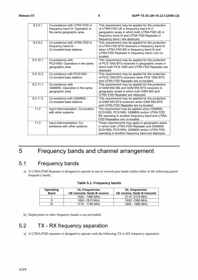
5.1 Frequency bands a) A UTRA/FDD Repeater is designed to operate in one or several pass bands within either of the following paired
frequency bands;
Table 5.1: Frequency bands
Operating Band
UL Frequencies UE transmit, Node B receive
DL frequencies UE receive, Node B transmit
I 1920 - 1980 MHz 2110 -2170 MHz II 1850 -1910 MHz 1930 -1990 MHz III 1710 - 1785 MHz 1805 - 1880 MHz
b) Deployment in other frequency bands is not precluded.
5.2 TX - RX frequency separation a) A UTRA/FDD repeaters is designed to operate with the following TX to RX frequency separation
3GPP
3GPP TS 25.106 V5.12.0 (2006-12)10Release 5T
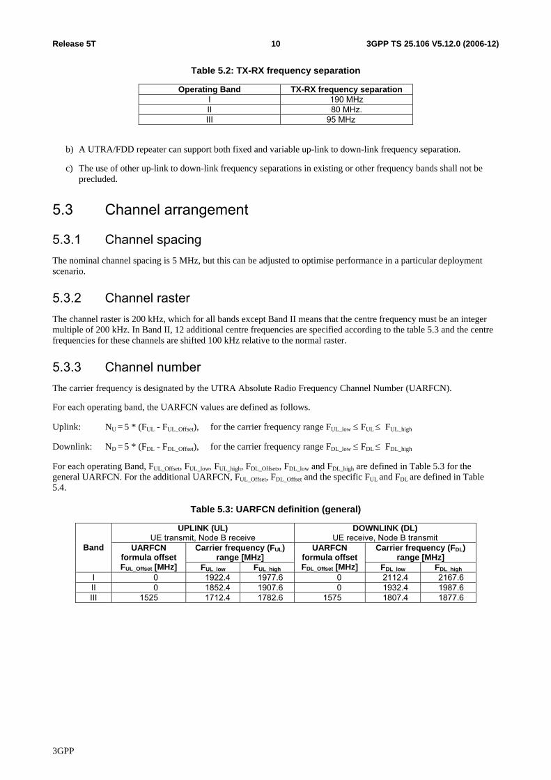
Table 5.2: TX-RX frequency separation
Operating Band TX-RX frequency separation I 190 MHz II 80 MHz. III 95 MHz
b) A UTRA/FDD repeater can support both fixed and variable up-link to down-link frequency separation.
c) The use of other up-link to down-link frequency separations in existing or other frequency bands shall not be precluded.
5.3 Channel arrangement
5.3.1 Channel spacing The nominal channel spacing is 5 MHz, but this can be adjusted to optimise performance in a particular deployment scenario.
5.3.2 Channel raster The channel raster is 200 kHz, which for all bands except Band II means that the centre frequency must be an integer multiple of 200 kHz. In Band II, 12 additional centre frequencies are specified according to the table 5.3 and the centre frequencies for these channels are shifted 100 kHz relative to the normal raster.
5.3.3 Channel number The carrier frequency is designated by the UTRA Absolute Radio Frequency Channel Number (UARFCN).
For each operating band, the UARFCN values are defined as follows.
Uplink: NU = 5 * (FUL - FUL_Offset), for the carrier frequency range FUL_low ≤ FUL ≤ FUL_high
Downlink: ND = 5 * (FDL - FDL_Offset), for the carrier frequency range FDL_low ≤ FDL ≤ FDL_high
For each operating Band, FUL_Offset, FUL_low, FUL_high, FDL_Offset,, FDL_low and FDL_high are defined in Table 5.3 for the general UARFCN. For the additional UARFCN, FUL_Offset, FDL_Offset and the specific FUL and FDL are defined in Table 5.4.
Table 5.3: UARFCN definition (general)
UPLINK (UL) UE transmit, Node B receive
DOWNLINK (DL) UE receive, Node B transmit
Carrier frequency (FUL) range [MHz]
Carrier frequency (FDL) range [MHz]
Band UARFCN formula offset FUL_Offset [MHz] FUL_low FUL_high
UARFCN formula offsetFDL_Offset [MHz] FDL_low FDL_high
I 0 1922.4 1977.6 0 2112.4 2167.6 II 0 1852.4 1907.6 0 1932.4 1987.6 III 1525 1712.4 1782.6 1575 1807.4 1877.6
3GPP
3GPP TS 25.106 V5.12.0 (2006-12)11Release 5T
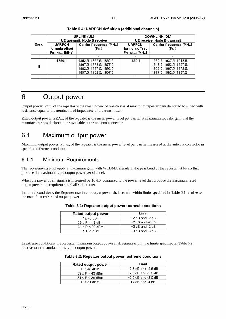
Table 5.4: UARFCN definition (additional channels)
UPLINK (UL) UE transmit, Node B receive
DOWNLINK (DL) UE receive, Node B transmit
Band UARFCN formula offset FUL_Offset [MHz]
Carrier frequency [MHz](FUL)
UARFCN formula offsetFDL_Offset [MHz]
Carrier frequency [MHz](FDL)
I - - - -
II
1850.1 1852.5, 1857.5, 1862.5, 1867.5, 1872.5, 1877.5, 1882.5, 1887.5, 1892.5, 1897.5, 1902.5, 1907.5
1850.1 1932.5, 1937.5, 1942.5, 1947.5, 1952.5, 1957.5, 1962.5, 1967.5, 1972.5, 1977.5, 1982.5, 1987.5
III - - - -
6 Output power Output power, Pout, of the repeater is the mean power of one carrier at maximum repeater gain delivered to a load with resistance equal to the nominal load impedance of the transmitter.
Rated output power, PRAT, of the repeater is the mean power level per carrier at maximum repeater gain that the manufacturer has declared to be available at the antenna connector.
6.1 Maximum output power Maximum output power, Pmax, of the repeater is the mean power level per carrier measured at the antenna connector in specified reference condition.
6.1.1 Minimum Requirements The requirements shall apply at maximum gain, with WCDMA signals in the pass band of the repeater, at levels that produce the maximum rated output power per channel.
When the power of all signals is increased by 10 dB, compared to the power level that produce the maximum rated output power, the requirements shall still be met.
In normal conditions, the Repeater maximum output power shall remain within limits specified in Table 6.1 relative to the manufacturer's rated output power.
Table 6.1: Repeater output power; normal conditions
Rated output power Limit P ≥ 43 dBm +2 dB and -2 dB
39 ≤ P < 43 dBm +2 dB and -2 dB 31 ≤ P < 39 dBm +2 dB and -2 dB
P < 31 dBm +3 dB and -3 dB
In extreme conditions, the Repeater maximum output power shall remain within the limits specified in Table 6.2 relative to the manufacturer's rated output power.
Table 6.2: Repeater output power; extreme conditions
Rated output power Limit P ≥ 43 dBm +2,5 dB and -2,5 dB
39 ≤ P < 43 dBm +2,5 dB and -2,5 dB 31 ≤ P < 39 dBm +2,5 dB and -2,5 dB
P < 31 dBm +4 dB and -4 dB
3GPP
3GPP TS 25.106 V5.12.0 (2006-12)12Release 5T
In certain regions, the minimum requirement for normal conditions may apply also for some conditions outside the ranges of conditions defined as normal.
7 Frequency stability Frequency stability is the ability to maintain the same frequency on the output signal with respect to the input signal.
7.1 Minimum requirement The frequency deviation of the output signal with respect to the input signal shall be no more than ±0,01 ppm.
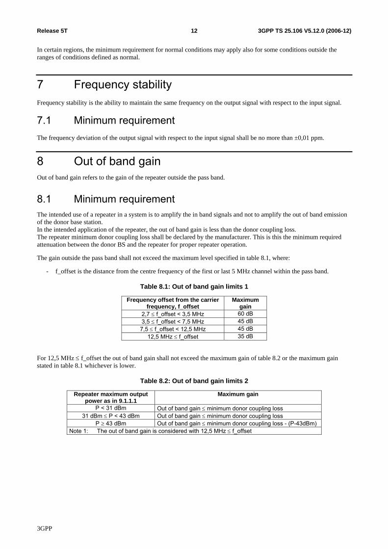
8 Out of band gain Out of band gain refers to the gain of the repeater outside the pass band.
8.1 Minimum requirement The intended use of a repeater in a system is to amplify the in band signals and not to amplify the out of band emission of the donor base station. In the intended application of the repeater, the out of band gain is less than the donor coupling loss. The repeater minimum donor coupling loss shall be declared by the manufacturer. This is this the minimum required attenuation between the donor BS and the repeater for proper repeater operation.
The gain outside the pass band shall not exceed the maximum level specified in table 8.1, where:
- f_offset is the distance from the centre frequency of the first or last 5 MHz channel within the pass band.
Table 8.1: Out of band gain limits 1
Frequency offset from the carrier frequency, f_offset
Maximum gain
2,7 ≤ f_offset < 3,5 MHz 60 dB 3,5 ≤ f_offset < 7,5 MHz 45 dB 7,5 ≤ f_offset < 12,5 MHz 45 dB
12,5 MHz ≤ f_offset 35 dB
For 12,5 MHz ≤ f_offset the out of band gain shall not exceed the maximum gain of table 8.2 or the maximum gain stated in table 8.1 whichever is lower.
Table 8.2: Out of band gain limits 2
Repeater maximum output power as in 9.1.1.1
Maximum gain
P < 31 dBm Out of band gain ≤ minimum donor coupling loss 31 dBm ≤ P < 43 dBm Out of band gain ≤ minimum donor coupling loss
P ≥ 43 dBm Out of band gain ≤ minimum donor coupling loss - (P-43dBm) Note 1: The out of band gain is considered with 12,5 MHz ≤ f_offset
3GPP
3GPP TS 25.106 V5.12.0 (2006-12)13Release 5T
9 Unwanted emission
9.1 Out of band emission Out of band emissions are unwanted emissions immediately outside the pass band resulting from the modulation process and non-linearity in the transmitter but excluding spurious emissions. This out of band emission requirement is specified in terms of a spectrum emission mask.
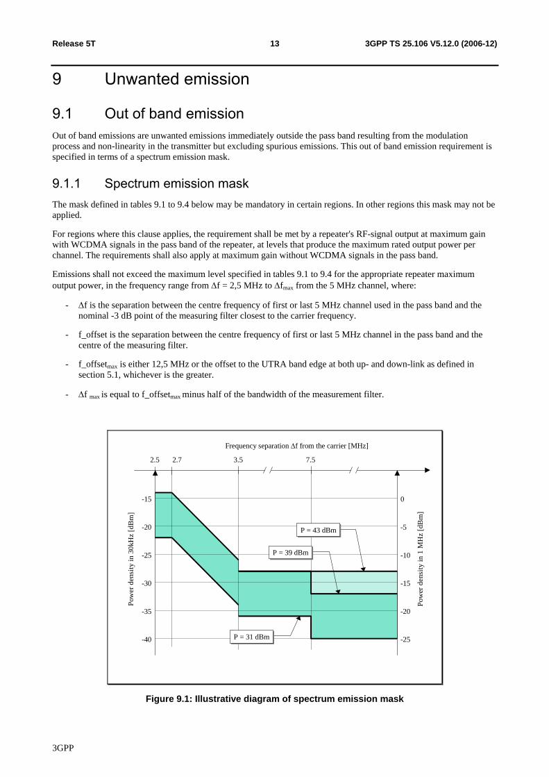
9.1.1 Spectrum emission mask The mask defined in tables 9.1 to 9.4 below may be mandatory in certain regions. In other regions this mask may not be applied.
For regions where this clause applies, the requirement shall be met by a repeater's RF-signal output at maximum gain with WCDMA signals in the pass band of the repeater, at levels that produce the maximum rated output power per channel. The requirements shall also apply at maximum gain without WCDMA signals in the pass band.
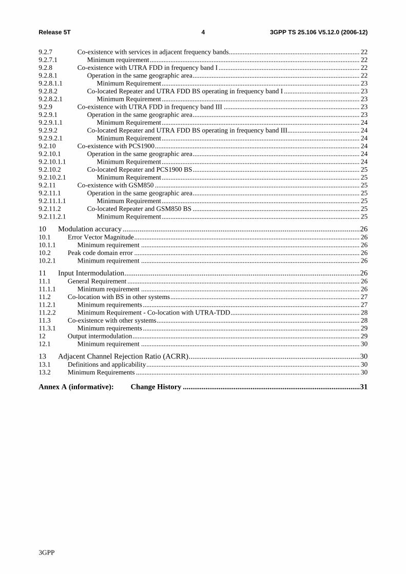
Emissions shall not exceed the maximum level specified in tables 9.1 to 9.4 for the appropriate repeater maximum output power, in the frequency range from Δf = 2,5 MHz to Δfmax from the 5 MHz channel, where:
- Δf is the separation between the centre frequency of first or last 5 MHz channel used in the pass band and the nominal -3 dB point of the measuring filter closest to the carrier frequency.
- f_offset is the separation between the centre frequency of first or last 5 MHz channel in the pass band and the centre of the measuring filter.
- f_offsetmax is either 12,5 MHz or the offset to the UTRA band edge at both up- and down-link as defined in section 5.1, whichever is the greater.
- Δf max is equal to f_offsetmax minus half of the bandwidth of the measurement filter.
2.5 2.7 3.5
-15 0
Frequency separation Δf from the carrier [MHz]
Pow
er d
ensi
ty in
30k
Hz
[dB
m]
-20
-25
-30
-35
-40
Pow
er d
ensi
ty in
1 M
Hz
[dB
m]
-5
-10
-15
-20
-25
7.5
P = 39 dBmP = 39 dBm
P = 43 dBmP = 43 dBm
P = 31 dBmP = 31 dBm
AM
Figure 9.1: Illustrative diagram of spectrum emission mask
3GPP
3GPP TS 25.106 V5.12.0 (2006-12)14Release 5T
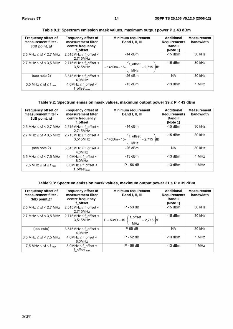
Table 9.1: Spectrum emission mask values, maximum output power P ≥ 43 dBm
Frequency offset of measurement filter -
3dB point, Δf
Frequency offset of measurement filter centre frequency,
f_offset
Minimum requirement Band I, II, III
Additional Requirements
Band II (Note 1)
Measurement bandwidth
2,5 MHz ≤ Δf < 2,7 MHz 2,515MHz ≤ f_offset < 2,715MHz
-14 dBm -15 dBm 30 kHz
2,7 MHz ≤ Δf < 3,5 MHz 2,715MHz ≤ f_offset < 3,515MHz dB2,715
MHz
f_offset1514dBm ⎟
⎠⎞
⎜⎝⎛
−⋅−−-15 dBm 30 kHz
(see note 2) 3,515MHz ≤ f_offset < 4,0MHz
-26 dBm NA 30 kHz
3,5 MHz ≤ Δf ≤ f max 4,0MHz ≤ f_offset < f_offsetmax
-13 dBm -13 dBm 1 MHz
Table 9.2: Spectrum emission mask values, maximum output power 39 ≤ P < 43 dBm
Frequency offset of measurement filter -
3dB point, Δf
Frequency offset of measurement filter centre frequency,
f_offset
Minimum requirement Band I, II, III
Additional Requirements
Band II (Note 1)
Measurement bandwidth
2,5 MHz ≤ Δf < 2,7 MHz 2,515MHz ≤ f_offset < 2,715MHz
-14 dBm -15 dBm 30 kHz
2,7 MHz ≤ Δf < 3,5 MHz 2,715MHz ≤ f_offset < 3,515MHz dB2,715
MHz
f_offset1514dBm ⎟
⎠⎞
⎜⎝⎛
−⋅−−-15 dBm 30 kHz
(see note 2) 3,515MHz ≤ f_offset < 4,0MHz
-26 dBm NA 30 kHz
3,5 MHz ≤ Δf < 7,5 MHz 4,0MHz ≤ f_offset < 8,0MHz
-13 dBm -13 dBm 1 MHz
7,5 MHz ≤ Δf ≤ f max 8,0MHz ≤ f_offset < f_offsetmax
P - 56 dB -13 dBm 1 MHz
Table 9.3: Spectrum emission mask values, maximum output power 31 ≤ P < 39 dBm
Frequency offset of measurement filter -
3dB point,Δf
Frequency offset of measurement filter centre frequency,
f_offset
Minimum requirement Band I, II, III
Additional Requirements
Band II (Note 1)
Measurement bandwidth
2,5 MHz ≤ Δf < 2,7 MHz 2,515MHz ≤ f_offset < 2,715MHz
P - 53 dB -15 dBm 30 kHz
2,7 MHz ≤ Δf < 3,5 MHz 2,715MHz ≤ f_offset < 3,515MHz dB2,715
MHz
f_offset1553dBP ⎟
⎠⎞
⎜⎝⎛
−⋅−−-15 dBm 30 kHz
(see note) 3,515MHz ≤ f_offset < 4,0MHz
P-65 dB NA 30 kHz
3,5 MHz ≤ Δf < 7,5 MHz 4,0MHz ≤ f_offset < 8,0MHz
P - 52 dB -13 dBm 1 MHz
7,5 MHz ≤ Δf ≤ f max 8,0MHz ≤ f_offset < f_offsetAmax
P - 56 dB -13 dBm 1 MHz
3GPP
3GPP TS 25.106 V5.12.0 (2006-12)15Release 5T
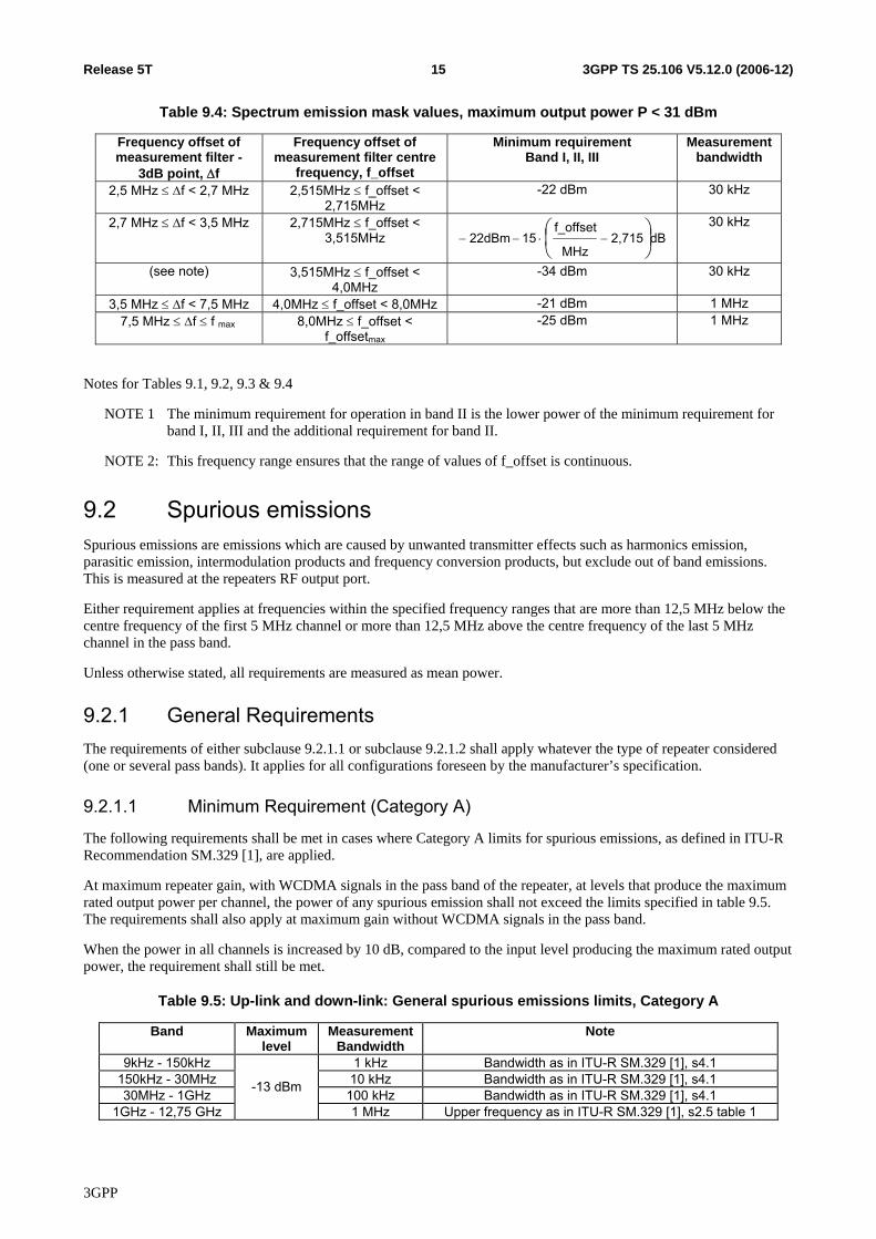
Table 9.4: Spectrum emission mask values, maximum output power P < 31 dBm
Frequency offset of measurement filter -
3dB point, Δf
Frequency offset of measurement filter centre
frequency, f_offset
Minimum requirement Band I, II, III
Measurement bandwidth
2,5 MHz ≤ Δf < 2,7 MHz 2,515MHz ≤ f_offset < 2,715MHz
-22 dBm 30 kHz
2,7 MHz ≤ Δf < 3,5 MHz 2,715MHz ≤ f_offset < 3,515MHz dB2,715
MHz
f_offset1522dBm ⎟
⎠⎞
⎜⎝⎛
−⋅−− 30 kHz
(see note) 3,515MHz ≤ f_offset < 4,0MHz
-34 dBm 30 kHz
3,5 MHz ≤ Δf < 7,5 MHz 4,0MHz ≤ f_offset < 8,0MHz -21 dBm 1 MHz 7,5 MHz ≤ Δf ≤ f max 8,0MHz ≤ f_offset <
f_offsetmax -25 dBm 1 MHz
Notes for Tables 9.1, 9.2, 9.3 & 9.4
NOTE 1 The minimum requirement for operation in band II is the lower power of the minimum requirement for band I, II, III and the additional requirement for band II.
NOTE 2: This frequency range ensures that the range of values of f_offset is continuous.
9.2 Spurious emissions Spurious emissions are emissions which are caused by unwanted transmitter effects such as harmonics emission, parasitic emission, intermodulation products and frequency conversion products, but exclude out of band emissions. This is measured at the repeaters RF output port.
Either requirement applies at frequencies within the specified frequency ranges that are more than 12,5 MHz below the centre frequency of the first 5 MHz channel or more than 12,5 MHz above the centre frequency of the last 5 MHz channel in the pass band.
Unless otherwise stated, all requirements are measured as mean power.
9.2.1 General Requirements The requirements of either subclause 9.2.1.1 or subclause 9.2.1.2 shall apply whatever the type of repeater considered (one or several pass bands). It applies for all configurations foreseen by the manufacturer’s specification.
9.2.1.1 Minimum Requirement (Category A)
The following requirements shall be met in cases where Category A limits for spurious emissions, as defined in ITU-R Recommendation SM.329 [1], are applied.
At maximum repeater gain, with WCDMA signals in the pass band of the repeater, at levels that produce the maximum rated output power per channel, the power of any spurious emission shall not exceed the limits specified in table 9.5. The requirements shall also apply at maximum gain without WCDMA signals in the pass band.
When the power in all channels is increased by 10 dB, compared to the input level producing the maximum rated output power, the requirement shall still be met.
Table 9.5: Up-link and down-link: General spurious emissions limits, Category A
Band Maximum level
Measurement Bandwidth
Note
9kHz - 150kHz 1 kHz Bandwidth as in ITU-R SM.329 [1], s4.1 150kHz - 30MHz 10 kHz Bandwidth as in ITU-R SM.329 [1], s4.1 30MHz - 1GHz 100 kHz Bandwidth as in ITU-R SM.329 [1], s4.1
1GHz - 12,75 GHz
-13 dBm
1 MHz Upper frequency as in ITU-R SM.329 [1], s2.5 table 1
3GPP
3GPP TS 25.106 V5.12.0 (2006-12)16Release 5T
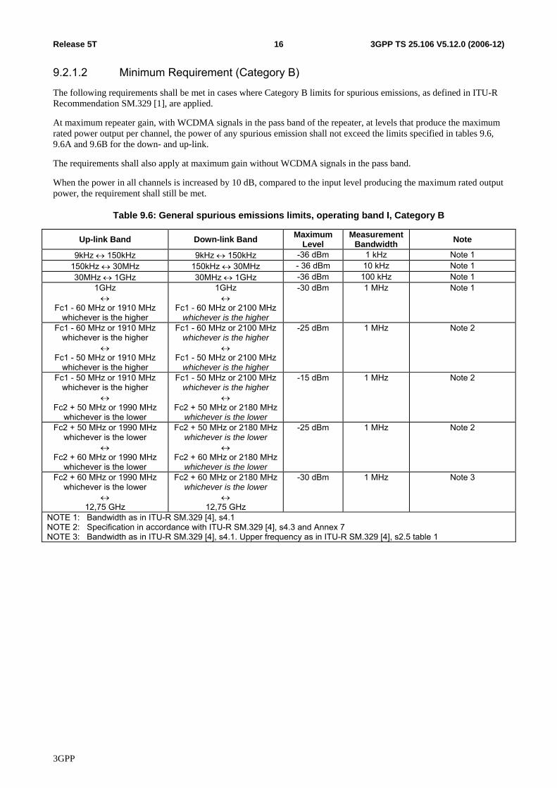
9.2.1.2 Minimum Requirement (Category B)
The following requirements shall be met in cases where Category B limits for spurious emissions, as defined in ITU-R Recommendation SM.329 [1], are applied.
At maximum repeater gain, with WCDMA signals in the pass band of the repeater, at levels that produce the maximum rated power output per channel, the power of any spurious emission shall not exceed the limits specified in tables 9.6, 9.6A and 9.6B for the down- and up-link.
The requirements shall also apply at maximum gain without WCDMA signals in the pass band.
When the power in all channels is increased by 10 dB, compared to the input level producing the maximum rated output power, the requirement shall still be met.
Table 9.6: General spurious emissions limits, operating band I, Category B
Up-link Band Down-link Band Maximum Level
Measurement Bandwidth Note
9kHz ↔ 150kHz 9kHz ↔ 150kHz -36 dBm 1 kHz Note 1 150kHz ↔ 30MHz 150kHz ↔ 30MHz - 36 dBm 10 kHz Note 1 30MHz ↔ 1GHz 30MHz ↔ 1GHz -36 dBm 100 kHz Note 1
1GHz ↔
Fc1 - 60 MHz or 1910 MHz whichever is the higher
1GHz ↔
Fc1 - 60 MHz or 2100 MHzwhichever is the higher
-30 dBm 1 MHz Note 1
Fc1 - 60 MHz or 1910 MHz whichever is the higher
↔ Fc1 - 50 MHz or 1910 MHz
whichever is the higher
Fc1 - 60 MHz or 2100 MHzwhichever is the higher
↔ Fc1 - 50 MHz or 2100 MHz
whichever is the higher
-25 dBm 1 MHz Note 2
Fc1 - 50 MHz or 1910 MHz whichever is the higher
↔ Fc2 + 50 MHz or 1990 MHz
whichever is the lower
Fc1 - 50 MHz or 2100 MHzwhichever is the higher
↔ Fc2 + 50 MHz or 2180 MHz
whichever is the lower
-15 dBm 1 MHz Note 2
Fc2 + 50 MHz or 1990 MHz whichever is the lower
↔ Fc2 + 60 MHz or 1990 MHz
whichever is the lower
Fc2 + 50 MHz or 2180 MHzwhichever is the lower
↔ Fc2 + 60 MHz or 2180 MHz
whichever is the lower
-25 dBm 1 MHz Note 2
Fc2 + 60 MHz or 1990 MHz whichever is the lower
↔ 12,75 GHz
Fc2 + 60 MHz or 2180 MHzwhichever is the lower
↔ 12,75 GHz
-30 dBm 1 MHz Note 3
NOTE 1: Bandwidth as in ITU-R SM.329 [4], s4.1 NOTE 2: Specification in accordance with ITU-R SM.329 [4], s4.3 and Annex 7 NOTE 3: Bandwidth as in ITU-R SM.329 [4], s4.1. Upper frequency as in ITU-R SM.329 [4], s2.5 table 1
3GPP
3GPP TS 25.106 V5.12.0 (2006-12)17Release 5T
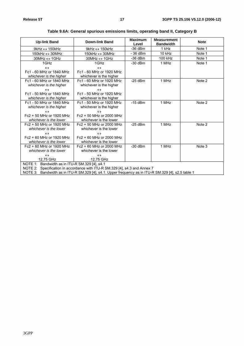
Table 9.6A: General spurious emissions limits, operating band II, Category B
Up-link Band Down-link Band Maximum Level
Measurement Bandwidth Note
9kHz ↔ 150kHz 9kHz ↔ 150kHz -36 dBm 1 kHz Note 1 150kHz ↔ 30MHz 150kHz ↔ 30MHz - 36 dBm 10 kHz Note 1 30MHz ↔ 1GHz 30MHz ↔ 1GHz -36 dBm 100 kHz Note 1
1GHz ↔
Fc1 - 60 MHz or 1840 MHz whichever is the higher
1GHz ↔
Fc1 - 60 MHz or 1920 MHzwhichever is the higher
-30 dBm 1 MHz Note 1
Fc1 - 60 MHz or 1840 MHz whichever is the higher
↔ Fc1 - 50 MHz or 1840 MHz
whichever is the higher
Fc1 - 60 MHz or 1920 MHzwhichever is the higher
↔ Fc1 - 50 MHz or 1920 MHz
whichever is the higher
-25 dBm 1 MHz Note 2
Fc1 - 50 MHz or 1840 MHz whichever is the higher
↔ Fc2 + 50 MHz or 1920 MHz
whichever is the lower
Fc1 - 50 MHz or 1920 MHzwhichever is the higher
↔ Fc2 + 50 MHz or 2000 MHz
whichever is the lower
-15 dBm 1 MHz Note 2
Fc2 + 50 MHz or 1920 MHz whichever is the lower
↔ Fc2 + 60 MHz or 1920 MHz
whichever is the lower
Fc2 + 50 MHz or 2000 MHzwhichever is the lower
↔ Fc2 + 60 MHz or 2000 MHz
whichever is the lower
-25 dBm 1 MHz Note 2
Fc2 + 60 MHz or 1920 MHz whichever is the lower
↔ 12,75 GHz
Fc2 + 60 MHz or 2000 MHzwhichever is the lower
↔ 12,75 GHz
-30 dBm 1 MHz Note 3
NOTE 1: Bandwidth as in ITU-R SM.329 [4], s4.1 NOTE 2: Specification in accordance with ITU-R SM.329 [4], s4.3 and Annex 7 NOTE 3: Bandwidth as in ITU-R SM.329 [4], s4.1. Upper frequency as in ITU-R SM.329 [4], s2.5 table 1
3GPP
3GPP TS 25.106 V5.12.0 (2006-12)18Release 5T
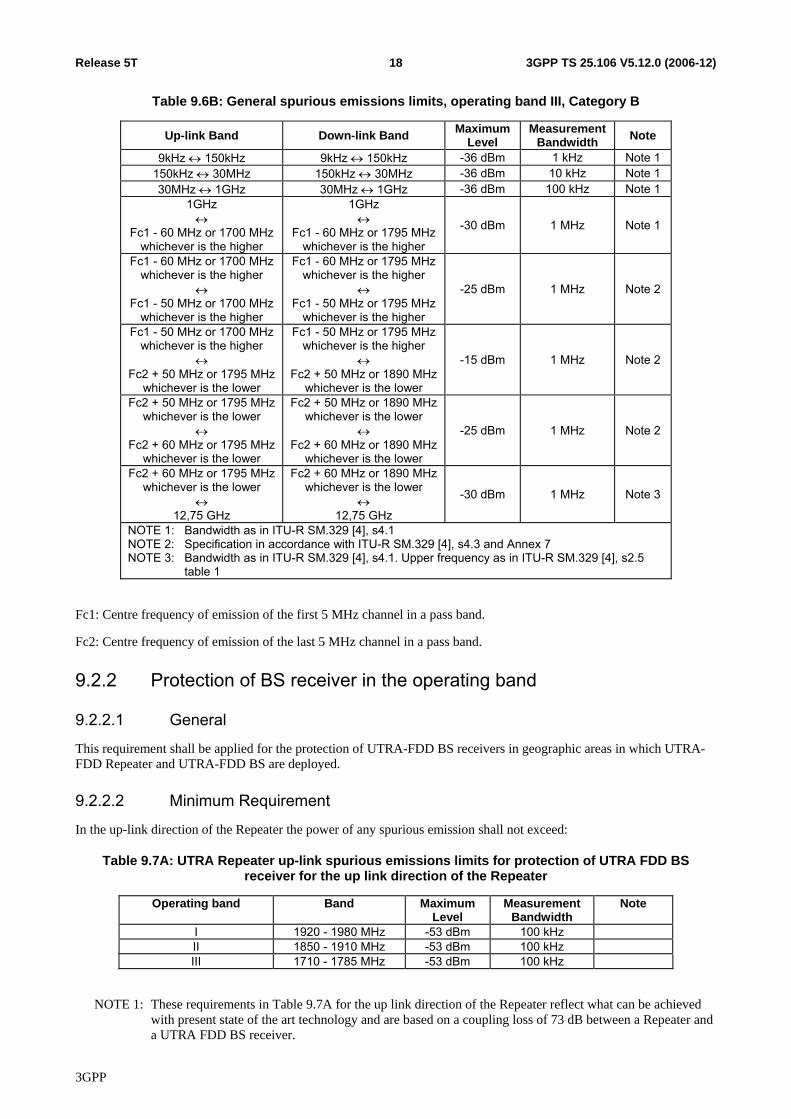
Table 9.6B: General spurious emissions limits, operating band III, Category B
Up-link Band Down-link Band Maximum Level
Measurement Bandwidth Note
9kHz ↔ 150kHz 9kHz ↔ 150kHz -36 dBm 1 kHz Note 1150kHz ↔ 30MHz 150kHz ↔ 30MHz -36 dBm 10 kHz Note 130MHz ↔ 1GHz 30MHz ↔ 1GHz -36 dBm 100 kHz Note 1
1GHz ↔
Fc1 - 60 MHz or 1700 MHz whichever is the higher
1GHz ↔
Fc1 - 60 MHz or 1795 MHzwhichever is the higher
-30 dBm 1 MHz Note 1
Fc1 - 60 MHz or 1700 MHz whichever is the higher
↔ Fc1 - 50 MHz or 1700 MHz
whichever is the higher
Fc1 - 60 MHz or 1795 MHzwhichever is the higher
↔ Fc1 - 50 MHz or 1795 MHz
whichever is the higher
-25 dBm 1 MHz Note 2
Fc1 - 50 MHz or 1700 MHz whichever is the higher
↔ Fc2 + 50 MHz or 1795 MHz
whichever is the lower
Fc1 - 50 MHz or 1795 MHzwhichever is the higher
↔ Fc2 + 50 MHz or 1890 MHz
whichever is the lower
-15 dBm 1 MHz Note 2
Fc2 + 50 MHz or 1795 MHz whichever is the lower
↔ Fc2 + 60 MHz or 1795 MHz
whichever is the lower
Fc2 + 50 MHz or 1890 MHzwhichever is the lower
↔ Fc2 + 60 MHz or 1890 MHz
whichever is the lower
-25 dBm 1 MHz Note 2
Fc2 + 60 MHz or 1795 MHz whichever is the lower
↔ 12,75 GHz
Fc2 + 60 MHz or 1890 MHzwhichever is the lower
↔ 12,75 GHz
-30 dBm 1 MHz Note 3
NOTE 1: Bandwidth as in ITU-R SM.329 [4], s4.1 NOTE 2: Specification in accordance with ITU-R SM.329 [4], s4.3 and Annex 7 NOTE 3: Bandwidth as in ITU-R SM.329 [4], s4.1. Upper frequency as in ITU-R SM.329 [4], s2.5
table 1
Fc1: Centre frequency of emission of the first 5 MHz channel in a pass band.
Fc2: Centre frequency of emission of the last 5 MHz channel in a pass band.
9.2.2 Protection of BS receiver in the operating band
9.2.2.1 General
This requirement shall be applied for the protection of UTRA-FDD BS receivers in geographic areas in which UTRA-FDD Repeater and UTRA-FDD BS are deployed.
9.2.2.2 Minimum Requirement
In the up-link direction of the Repeater the power of any spurious emission shall not exceed:
Table 9.7A: UTRA Repeater up-link spurious emissions limits for protection of UTRA FDD BS receiver for the up link direction of the Repeater
Operating band Band Maximum Level
Measurement Bandwidth
Note
I 1920 - 1980 MHz -53 dBm 100 kHz II 1850 - 1910 MHz -53 dBm 100 kHz III 1710 - 1785 MHz -53 dBm 100 kHz
NOTE 1: These requirements in Table 9.7A for the up link direction of the Repeater reflect what can be achieved with present state of the art technology and are based on a coupling loss of 73 dB between a Repeater and a UTRA FDD BS receiver.
3GPP
3GPP TS 25.106 V5.12.0 (2006-12)19Release 5T
NOTE 2: The requirements shall be reconsidered when the state of the art technology progresses.
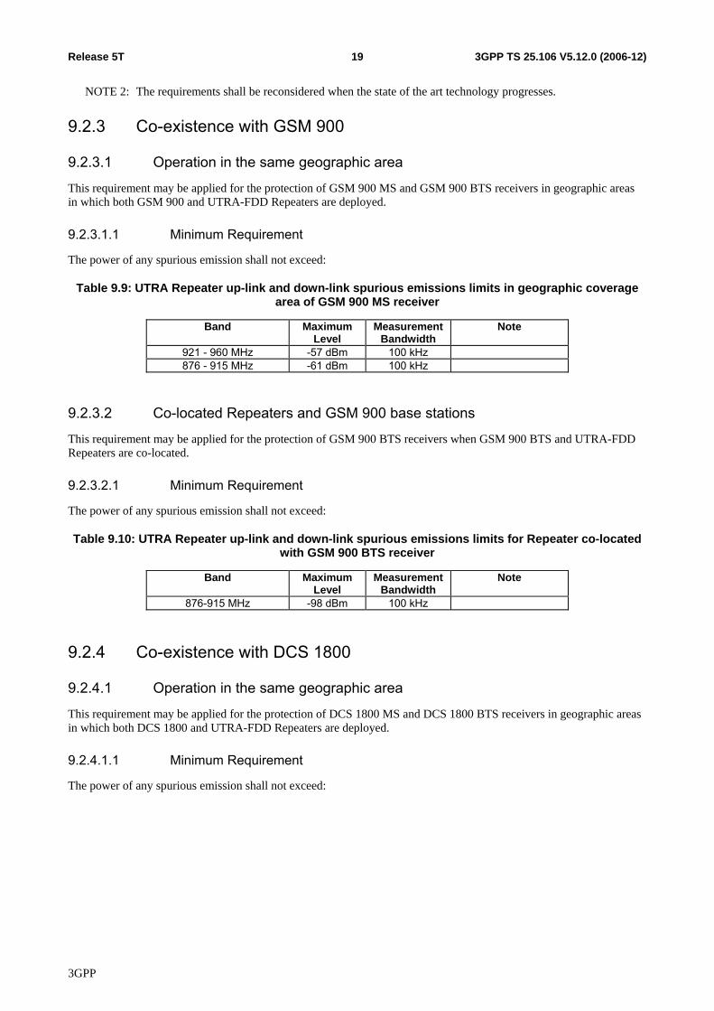
9.2.3 Co-existence with GSM 900
9.2.3.1 Operation in the same geographic area
This requirement may be applied for the protection of GSM 900 MS and GSM 900 BTS receivers in geographic areas in which both GSM 900 and UTRA-FDD Repeaters are deployed.
9.2.3.1.1 Minimum Requirement
The power of any spurious emission shall not exceed:
Table 9.9: UTRA Repeater up-link and down-link spurious emissions limits in geographic coverage area of GSM 900 MS receiver
Band Maximum Level
Measurement Bandwidth
Note
921 - 960 MHz -57 dBm 100 kHz 876 - 915 MHz -61 dBm 100 kHz
9.2.3.2 Co-located Repeaters and GSM 900 base stations
This requirement may be applied for the protection of GSM 900 BTS receivers when GSM 900 BTS and UTRA-FDD Repeaters are co-located.
9.2.3.2.1 Minimum Requirement
The power of any spurious emission shall not exceed:
Table 9.10: UTRA Repeater up-link and down-link spurious emissions limits for Repeater co-located with GSM 900 BTS receiver
Band Maximum Level
Measurement Bandwidth
Note
876-915 MHz -98 dBm 100 kHz
9.2.4 Co-existence with DCS 1800
9.2.4.1 Operation in the same geographic area
This requirement may be applied for the protection of DCS 1800 MS and DCS 1800 BTS receivers in geographic areas in which both DCS 1800 and UTRA-FDD Repeaters are deployed.
9.2.4.1.1 Minimum Requirement
The power of any spurious emission shall not exceed:
3GPP
3GPP TS 25.106 V5.12.0 (2006-12)20Release 5T
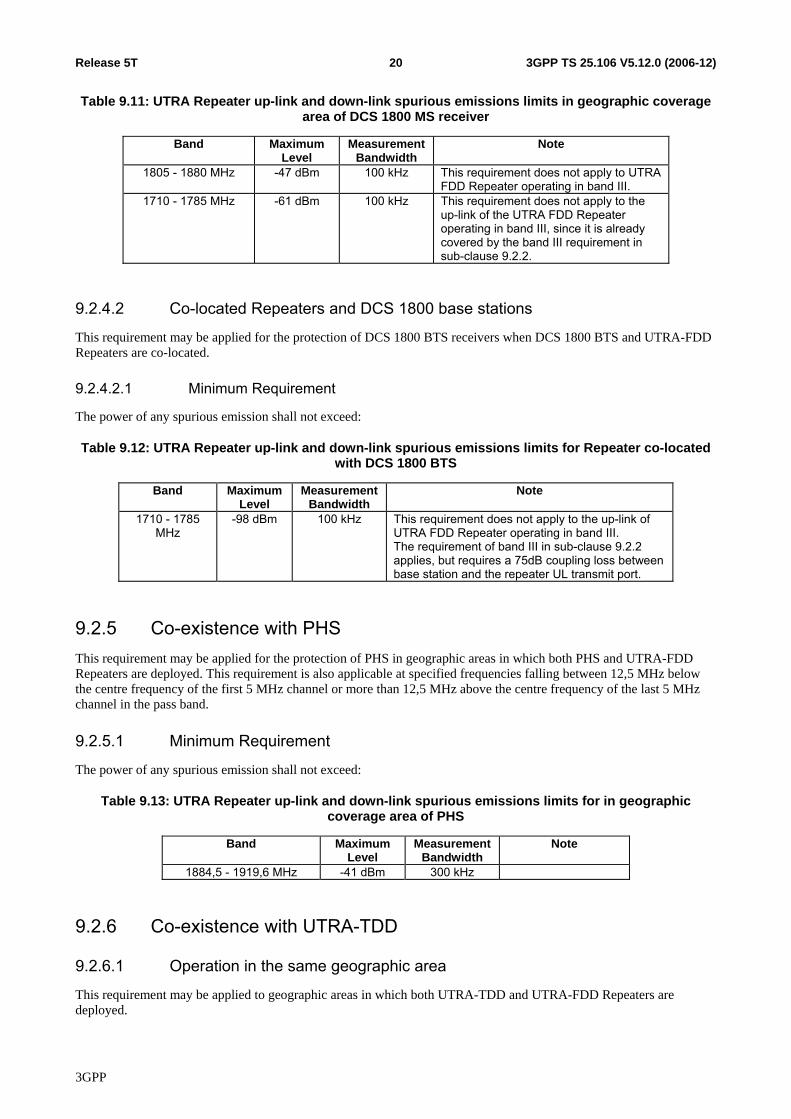
Table 9.11: UTRA Repeater up-link and down-link spurious emissions limits in geographic coverage area of DCS 1800 MS receiver
Band Maximum Level
Measurement Bandwidth
Note
1805 - 1880 MHz -47 dBm 100 kHz This requirement does not apply to UTRA FDD Repeater operating in band III.
1710 - 1785 MHz -61 dBm 100 kHz This requirement does not apply to the up-link of the UTRA FDD Repeater operating in band III, since it is already covered by the band III requirement in sub-clause 9.2.2.
9.2.4.2 Co-located Repeaters and DCS 1800 base stations
This requirement may be applied for the protection of DCS 1800 BTS receivers when DCS 1800 BTS and UTRA-FDD Repeaters are co-located.
9.2.4.2.1 Minimum Requirement
The power of any spurious emission shall not exceed:
Table 9.12: UTRA Repeater up-link and down-link spurious emissions limits for Repeater co-located with DCS 1800 BTS
Band Maximum Level
Measurement Bandwidth
Note
1710 - 1785 MHz
-98 dBm 100 kHz This requirement does not apply to the up-link of UTRA FDD Repeater operating in band III. The requirement of band III in sub-clause 9.2.2 applies, but requires a 75dB coupling loss between base station and the repeater UL transmit port.
9.2.5 Co-existence with PHS This requirement may be applied for the protection of PHS in geographic areas in which both PHS and UTRA-FDD Repeaters are deployed. This requirement is also applicable at specified frequencies falling between 12,5 MHz below the centre frequency of the first 5 MHz channel or more than 12,5 MHz above the centre frequency of the last 5 MHz channel in the pass band.
9.2.5.1 Minimum Requirement
The power of any spurious emission shall not exceed:
Table 9.13: UTRA Repeater up-link and down-link spurious emissions limits for in geographic coverage area of PHS
Band Maximum Level
Measurement Bandwidth
Note
1884,5 - 1919,6 MHz -41 dBm 300 kHz
9.2.6 Co-existence with UTRA-TDD
9.2.6.1 Operation in the same geographic area
This requirement may be applied to geographic areas in which both UTRA-TDD and UTRA-FDD Repeaters are deployed.
3GPP
3GPP TS 25.106 V5.12.0 (2006-12)21Release 5T
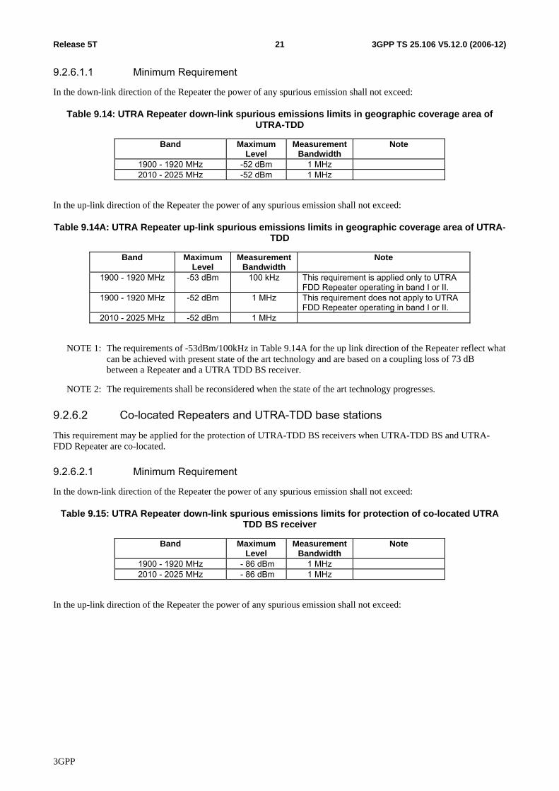
9.2.6.1.1 Minimum Requirement
In the down-link direction of the Repeater the power of any spurious emission shall not exceed:
Table 9.14: UTRA Repeater down-link spurious emissions limits in geographic coverage area of UTRA-TDD
Band Maximum Level
Measurement Bandwidth
Note
1900 - 1920 MHz -52 dBm 1 MHz 2010 - 2025 MHz -52 dBm 1 MHz
In the up-link direction of the Repeater the power of any spurious emission shall not exceed:
Table 9.14A: UTRA Repeater up-link spurious emissions limits in geographic coverage area of UTRA-TDD
Band Maximum Level
Measurement Bandwidth
Note
1900 - 1920 MHz -53 dBm 100 kHz This requirement is applied only to UTRA FDD Repeater operating in band I or II.
1900 - 1920 MHz -52 dBm 1 MHz This requirement does not apply to UTRA FDD Repeater operating in band I or II.
2010 - 2025 MHz -52 dBm 1 MHz
NOTE 1: The requirements of -53dBm/100kHz in Table 9.14A for the up link direction of the Repeater reflect what can be achieved with present state of the art technology and are based on a coupling loss of 73 dB between a Repeater and a UTRA TDD BS receiver.
NOTE 2: The requirements shall be reconsidered when the state of the art technology progresses.
9.2.6.2 Co-located Repeaters and UTRA-TDD base stations
This requirement may be applied for the protection of UTRA-TDD BS receivers when UTRA-TDD BS and UTRA-FDD Repeater are co-located.
9.2.6.2.1 Minimum Requirement
In the down-link direction of the Repeater the power of any spurious emission shall not exceed:
Table 9.15: UTRA Repeater down-link spurious emissions limits for protection of co-located UTRA TDD BS receiver
Band Maximum Level
Measurement Bandwidth
Note
1900 - 1920 MHz - 86 dBm 1 MHz 2010 - 2025 MHz - 86 dBm 1 MHz
In the up-link direction of the Repeater the power of any spurious emission shall not exceed:
3GPP

3GPP TS 25.106 V5.12.0 (2006-12)22Release 5T
Table 9.15A: UTRA Repeater up-link spurious emissions limits for protection of co-located UTRA TDD BS receiver
Band Maximum Level
Measurement Bandwidth
Note
1900 - 1920 MHz -53 dBm 100 kHz This requirement is applied only to UTRA FDD Repeater operating in band I or II.
1900 - 1920 MHz -86 dBm 1 MHz This requirement does not apply to UTRA FDD Repeater operating in band I or II.
2010 - 2025 MHz -83 dBm 100 kHz This requirement is applied only to UTRA FDD Repeater operating in band I.
2010 - 2025 MHz -86 dBm 1 MHz This requirement does not apply to UTRA FDD Repeater operating in band I
NOTE 1: The requirements of -53dBm/100kHz in Table 9.15A for the up link direction of the Repeater reflect what can be achieved with present state of the art technology and are based on a coupling loss of 73 dB between a Repeater and a UTRA TDD BS receiver.
NOTE 2: The requirements of -83dBm/100kHz in Table 9.15A for the up link direction of the Repeater reflect what can be achieved with present state of the art technology and are based on a coupling loss of 43 dB between a Repeater and a UTRA TDD BS receiver.
NOTE 3: The requirements shall be reconsidered when the state of the art technology progresses.
9.2.7 Co-existence with services in adjacent frequency bands This requirement may be applied for the protection in bands adjacent to bands I or II, as defined in clause 5.1 in geographic areas in which both an adjacent band service and UTRA are deployed.
The requirement applies only to the down-link direction of the repeater.
9.2.7.1 Minimum requirement
The power of any spurious emission shall not exceed:
Table 9.16: UTRA Repeater down-link spurious emissions limits for protection of adjacent band services
Operating Band
Band Maximum Level Measurement Bandwidth
Note
2100-2105 MHz -30 + 3.4 (f - 2100 MHz) dBm 1 MHz I 2175-2180 MHz -30 + 3.4 (2180 MHz - f) dBm 1 MHz 1920-1925 MHz -30 + 3.4 (f - 1920 MHz) dBm 1 MHz II 1995-2000 MHz -30 + 3.4 (2000 MHz - f) dBm 1 MHz 1795-1800 MHz -30 + 3.4 (f - 1795 MHz) dBm 1 MHz III 1885-1890 MHz -30 + 3.4 (1890 MHz - f) dBm 1 MHz
9.2.8 Co-existence with UTRA FDD in frequency band I
9.2.8.1 Operation in the same geographic area
This requirement may be applied for the protection of UTRA FDD UE and BS operating in frequency band I in geographic areas in which both UTRA FDD in frequency band I and UTRA-FDD Repeater in other bands are deployed.
3GPP

3GPP TS 25.106 V5.12.0 (2006-12)23Release 5T
9.2.8.1.1 Minimum Requirement
The power of any spurious emission shall not exceed:
Table 9.17: UTRA Repeater up-link and down-link spurious emissions limits in geographic coverage area of UTRA FDD UE receiver and BS receiver operating in frequency band I
Band Maximum Level Measurement Bandwidth
Note
2110 - 2170 MHz -52 dBm 1 MHz This requirement does not apply to UTRA FDD Repeater operating in band I.
1920 - 1980 MHz -49 dBm 1 MHz This requirement does not apply to the up-link of the UTRA FDD Repeater operating in band I, since it is already covered by the band I requirement in sub-clause 9.2.2.
9.2.8.2 Co-located Repeater and UTRA FDD BS operating in frequency band I
This requirement may be applied for the protection of UTRA FDD BS receivers operating in frequency band I when UTRA FDD BS operating in frequency band I and UTRA-FDD Repeater operating in other frequency bandsare co-located.
9.2.8.2.1 Minimum Requirement
The power of any spurious emission shall not exceed:
Table 9.18: UTRA Repeater up-link and down-link spurious emissions limits for Repeater co-located with UTRA BS operating in frequency band I
Band Maximum Level
Measurement Bandwidth
Note
1920 - 1980 MHz -96 dBm 100 kHz This requirement does not apply to the up-link of UTRA FDD Repeater operating in band I. The requirement of band I in sub-clause 9.2.2 applies, but requires a 73dB coupling loss between base station and the repeater UL transmit port.
9.2.9 Co-existence with UTRA FDD in frequency band III
9.2.9.1 Operation in the same geographic area
This requirement may be applied for the protection of UTRA FDD UE and BS operating in frequency band III in geographic areas in which both UTRA FDD in frequency band III and UTRA-FDD Repeater in other frequency bands are deployed.
3GPP
3GPP TS 25.106 V5.12.0 (2006-12)24Release 5T
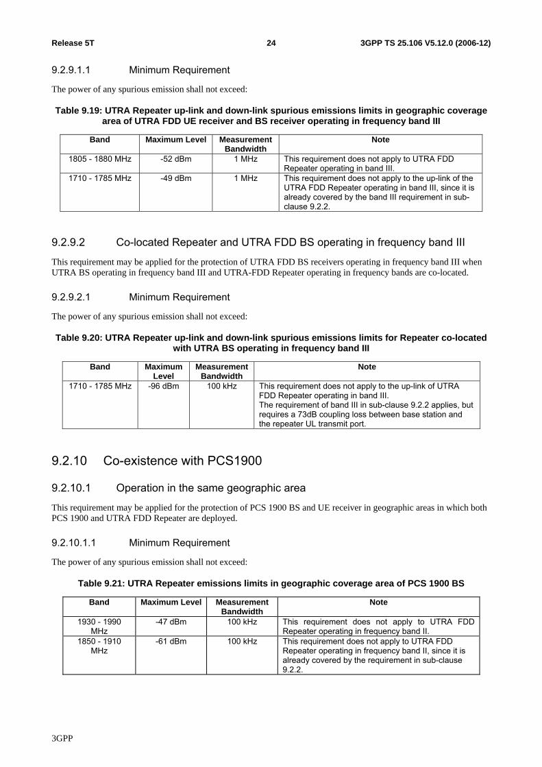
9.2.9.1.1 Minimum Requirement
The power of any spurious emission shall not exceed:
Table 9.19: UTRA Repeater up-link and down-link spurious emissions limits in geographic coverage area of UTRA FDD UE receiver and BS receiver operating in frequency band III
Band Maximum Level Measurement Bandwidth
Note
1805 - 1880 MHz -52 dBm 1 MHz This requirement does not apply to UTRA FDD Repeater operating in band III.
1710 - 1785 MHz -49 dBm 1 MHz This requirement does not apply to the up-link of the UTRA FDD Repeater operating in band III, since it is already covered by the band III requirement in sub-clause 9.2.2.
9.2.9.2 Co-located Repeater and UTRA FDD BS operating in frequency band III
This requirement may be applied for the protection of UTRA FDD BS receivers operating in frequency band III when UTRA BS operating in frequency band III and UTRA-FDD Repeater operating in frequency bands are co-located.
9.2.9.2.1 Minimum Requirement
The power of any spurious emission shall not exceed:
Table 9.20: UTRA Repeater up-link and down-link spurious emissions limits for Repeater co-located with UTRA BS operating in frequency band III
Band Maximum Level
Measurement Bandwidth
Note
1710 - 1785 MHz -96 dBm 100 kHz This requirement does not apply to the up-link of UTRA FDD Repeater operating in band III. The requirement of band III in sub-clause 9.2.2 applies, but requires a 73dB coupling loss between base station and the repeater UL transmit port.
9.2.10 Co-existence with PCS1900
9.2.10.1 Operation in the same geographic area
This requirement may be applied for the protection of PCS 1900 BS and UE receiver in geographic areas in which both PCS 1900 and UTRA FDD Repeater are deployed.
9.2.10.1.1 Minimum Requirement
The power of any spurious emission shall not exceed:
Table 9.21: UTRA Repeater emissions limits in geographic coverage area of PCS 1900 BS
Band Maximum Level Measurement Bandwidth
Note
1930 - 1990 MHz
-47 dBm 100 kHz This requirement does not apply to UTRA FDD Repeater operating in frequency band II.
1850 - 1910 MHz
-61 dBm 100 kHz This requirement does not apply to UTRA FDD Repeater operating in frequency band II, since it is already covered by the requirement in sub-clause 9.2.2.
3GPP
3GPP TS 25.106 V5.12.0 (2006-12)25Release 5T
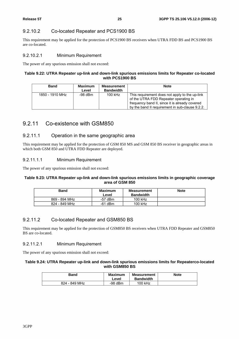
9.2.10.2 Co-located Repeater and PCS1900 BS
This requirement may be applied for the protection of PCS1900 BS receivers when UTRA FDD BS and PCS1900 BS are co-located.
9.2.10.2.1 Minimum Requirement
The power of any spurious emission shall not exceed:
Table 9.22: UTRA Repeater up-link and down-link spurious emissions limits for Repeater co-located with PCS1900 BS
Band Maximum Level
Measurement Bandwidth
Note
1850 - 1910 MHz -98 dBm 100 kHz This requirement does not apply to the up-link of the UTRA FDD Repeater operating in frequency band II, since it is already covered by the band II requirement in sub-clause 9.2.2.
9.2.11 Co-existence with GSM850
9.2.11.1 Operation in the same geographic area
This requirement may be applied for the protection of GSM 850 MS and GSM 850 BS receiver in geographic areas in which both GSM 850 and UTRA FDD Repeater are deployed.
9.2.11.1.1 Minimum Requirement
The power of any spurious emission shall not exceed:
Table 9.23: UTRA Repeater up-link and down-link spurious emissions limits in geographic coverage area of GSM 850
Band Maximum Level
Measurement Bandwidth
Note
869 - 894 MHz -57 dBm 100 kHz 824 - 849 MHz -61 dBm 100 kHz
9.2.11.2 Co-located Repeater and GSM850 BS
This requirement may be applied for the protection of GSM850 BS receivers when UTRA FDD Repeater and GSM850 BS are co-located.
9.2.11.2.1 Minimum Requirement
The power of any spurious emission shall not exceed:
Table 9.24: UTRA Repeater up-link and down-link spurious emissions limits for Repeaterco-located with GSM850 BS
Band Maximum Level
Measurement Bandwidth
Note
824 - 849 MHz -98 dBm 100 kHz
3GPP
3GPP TS 25.106 V5.12.0 (2006-12)26Release 5T
10 Modulation accuracy
10.1 Error Vector Magnitude The modulation accuracy is defined by the Error Vector Magnitude (EVM), which is a measure of the difference between the theoretical waveform and a modified version of the measured waveform. This difference is called the error vector. The measured waveform is modified by first passing it through a matched root raised cosine filter with bandwidth 3.84 MHz and roll-off α=0.22. The waveform is then further modified by selecting the frequency, absolute phase, absolute amplitude and chip clock timing so as to minimise the error vector. The EVM result is defined as root of the ratio of the mean error vector power to the mean reference signal power expressed as a %.
The measurement interval is one power control group (timeslot). The repeater shall operate with an ideal WCDMA signal in the pass band of the repeater at a level, which produce the maximum rated output power per channel, as specified by the manufacturer.
10.1.1 Minimum requirement The Error Vector Magnitude shall not be worse than 12,5 %.
10.2 Peak code domain error The peak code domain error is computed by projecting the power of the error vector (as defined in subclause 10.1) onto the code domain at a specified spreading factor. The code domain error for every code in the domain is defined as the ratio of the mean power of the projection onto that code, to the mean power of the composite reference waveform. This ratio is expressed in dB. The peak code domain error is defined as the maximum value for the code domain error for all codes. The measurement interval is one power control group (timeslot).
10.2.1 Minimum requirement The peak code domain error shall not exceed -35 dB at spreading factor 256.
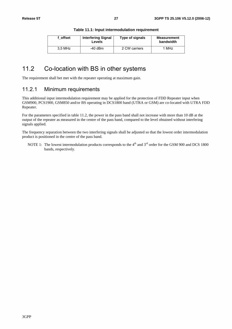
11 Input Intermodulation The input intermodulation is a measure of the capability of the repeater to inhibit the generation of interference in the pass band, in the presence of interfering signals on frequencies other than the pass band.
11.1 General Requirement The following requirement applies for interfering signals in the frequency bands defined in sub-clause 5.1, depending on the repeaters pass band. The requirement shall bet met with the repeater operating at maximum gain.
11.1.1 Minimum requirement For the parameters specified in table 11.1, the power in the pass band, shall not increase with more than 10 dB at the output of the repeater as measured in the centre of the pass band, compared to the level obtained without interfering signals applied.
The frequency separation between the two interfering signals shall be adjusted so that the 3rd order intermodulation product is positioned in the centre of the pass band.
Table 11.1 specifies the parameters for two interfering signals, where:
− f_offset is the separation between the centre frequency of first or last 5 MHz channel in the pass band and one the interfering signals.
3GPP
3GPP TS 25.106 V5.12.0 (2006-12)27Release 5T
Table 11.1: Input intermodulation requirement
f_offset Interfering Signal Levels
Type of signals Measurement bandwidth
3,5 MHz -40 dBm 2 CW carriers 1 MHz
11.2 Co-location with BS in other systems The requirement shall bet met with the repeater operating at maximum gain.
11.2.1 Minimum requirements This additional input intermodulation requirement may be applied for the protection of FDD Repeater input when GSM900, PCS1900, GSM850 and/or BS operating in DCS1800 band (UTRA or GSM) are co-located with UTRA FDD Repeater.
For the parameters specified in table 11.2, the power in the pass band shall not increase with more than 10 dB at the output of the repeater as measured in the centre of the pass band, compared to the level obtained without interfering signals applied.
The frequency separation between the two interfering signals shall be adjusted so that the lowest order intermodulation product is positioned in the centre of the pass band.
NOTE 1: The lowest intermodulation products corresponds to the 4th and 3rd order for the GSM 900 and DCS 1800 bands, respectively.
3GPP

3GPP TS 25.106 V5.12.0 (2006-12)28Release 5T
Table 11.2: Input intermodulation requirements for interfering signals in other systems
Co-located other
systems
Frequency of interfering
signals
Interfering Signal Levels
Type of signals
Measurement bandwidth
Note
GSM900 921 - 960 MHz +16 dBm 2 CW carriers
1 MHz This requirement does not apply to UTRA FDD Repeater operating in band VIII, since it is already covered by the requirement in sub-clause 11.1, but requires a 86dB coupling loss between base station and the repeater DL receive port.
DCS1800 1805 - 1880 MHz +16 dBm 2 CW carriers
1 MHz This requirement does not apply to UTRA FDD Repeater operating in band III, since it is already covered by the requirement in sub-clause 11.1, but requires a 86dB coupling loss between base station and the repeater DL receive port.
PCS1900 1930 - 1990 MHz +16 dBm 2 CW carriers
1 MHz This requirement does not apply to UTRA FDD Repeater operating in band II, since it is already covered by the requirement in sub-clause 11.1, but requires a 86dB coupling loss between base station and the repeater DL receive port.
GSM850 869 - 894 MHz +16 dBm 2 CW carriers
1 MHz This requirement does not apply to UTRA FDD Repeater operating in band V, since it is already covered by the requirement in sub-clause 11.1, but requires a 86dB coupling loss between base station and the repeater DL receive port.
UTRA-FDD Band I
2110 - 2170 MHz +16 dBm 2 CW carriers
1 MHz This requirement does not apply to UTRA FDD Repeater operating in band I, since it is already covered by the requirement in sub-clause 11.1, but requires a 86dB coupling loss between base station and the repeater DL receive port.
UTRA-FDD Band II
1930 - 1990 MHz +16 dBm 2 CW carriers
1 MHz This requirement does not apply to UTRA FDD Repeater operating in band II, since it is already covered by the requirement in sub-clause 11.1, but requires a 86dB coupling loss between base station and the repeater DL receive port.
UTRA-FDD Band III
1805 - 1880 MHz +16 dBm 2 CW carriers
1 MHz This requirement does not apply to UTRA FDD Repeater operating in band III, since it is already covered by the requirement in sub-clause 11.1, but requires a 86dB coupling loss between base station and the repeater DL receive port.
11.2.2 Minimum Requirement - Co-location with UTRA-TDD The current state-of-the-art technology does not allow a single generic solution for co-location with UTRA-TDD on adjacent frequencies for 30dB BS-Repeater minimum coupling loss.
However, there are certain site-engineering solutions that can be used. These techniques are addressed in TR 25.942 [5].
11.3 Co-existence with other systems The following requirement may be applied when GSM 900, DCS 1800, PCS1900, GSM850 and/or UTRA FDD BS operating in another frequency band and UTRA-FDD Repeaters co-exist. The requirement shall bet met with the repeater operating at maximum gain.
3GPP

3GPP TS 25.106 V5.12.0 (2006-12)29Release 5T
11.3.1 Minimum requirements For the parameters specified in table 11.3, the power in the pass band shall not increase with more than 10 dB at the output of the repeater as measured in the centre of the pass band, compared to the level obtained without interfering signals applied.
The frequency separation between the two interfering signals shall be adjusted so that the lowest order intermodulation product is positioned in the centre of the pass band.
NOTE 1: The lowest intermodulation products corresponds to the 4th and 3rd order for the GSM 900 and DCS 1800 bands, respectively.
Table 11.3: Input intermodulation requirements for interfering signals in other systems
Co-existence with other systems
Frequency of interfering
signals
Interfering Signal Levels
Type of signals
Measurement bandwidth
Note
GSM900 876 - 915 MHz -15 dBm 2 CW carriers
1 MHz This requirement does not apply to UTRA FDD Repeater operating in band VIII, since it is already covered by the requirement in sub-clause 11.1
DCS1800 1710 - 1785 MHz -15 dBm 2 CW carriers
1 MHz This requirement does not apply to UTRA FDD Repeater operating in band III, since it is already covered by the requirement in sub-clause 11.1
PCS1900 1850 - 1910 MHz -15 dBm 2 CW carriers
1 MHz This requirement does not apply to UTRA FDD Repeater operating in band II, since it is already covered by the requirement in sub-clause 11.1
GSM850 824 - 849 MHz -15 dBm 2 CW carriers
1 MHz This requirement does not apply to UTRA FDD Repeater operating in band V, since it is already covered by the requirement in sub-clause 11.1
UTRA-FDD Band I
1920 - 1980 MHz -15 dBm 2 CW carriers
1 MHz This requirement does not apply to UTRA FDD Repeater operating in band I, since it is already covered by the requirement in sub-clause 11.1.
UTRA-FDD Band II
1850 - 1910 MHz -15 dBm 2 CW carriers
1 MHz This requirement does not apply to UTRA FDD Repeater operating in band II, since it is already covered by the requirement in sub-clause 11.1.
UTRA-FDD Band III
1710 - 1785 MHz -15 dBm 2 CW carriers
1 MHz This requirement does not apply to UTRA FDD Repeater operating in band III, since it is already covered by the requirement in sub-clause 11.1.
12 Output intermodulation The output intermodulation requirement is a measure of the ability of the repeater to inhibit the generation of intermodulation products signals created by the presence of an interfering signal reaching the repeater via the output port.
The output intermodulation level is the power of the intermodulation products when a WCDMA modulated interference signal is injected into the output port at a level of 30 dB lower than that of the wanted signal. The frequency of the interference signal shall be ±5 MHz, ±10 MHz and ±15 MHz offset from the wanted signal, but within the frequency band allocated for UTRA FDD downlink as specified in subclause 4.1.
The requirement is applicable for downlink signals.
3GPP
3GPP TS 25.106 V5.12.0 (2006-12)30Release 5T
12.1 Minimum requirement The output intermodulation level shall not exceed the out of band emission or the spurious emission requirements of section 9.1 and 9.2.
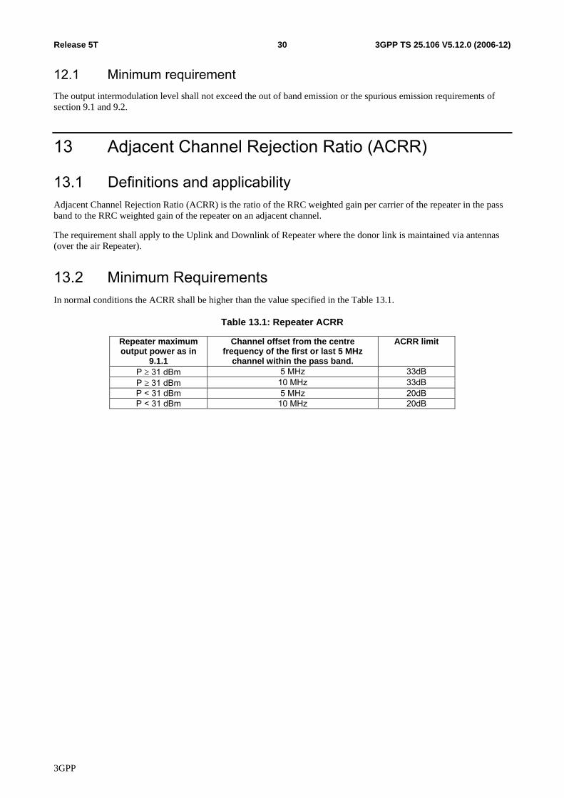
13 Adjacent Channel Rejection Ratio (ACRR)
13.1 Definitions and applicability Adjacent Channel Rejection Ratio (ACRR) is the ratio of the RRC weighted gain per carrier of the repeater in the pass band to the RRC weighted gain of the repeater on an adjacent channel.
The requirement shall apply to the Uplink and Downlink of Repeater where the donor link is maintained via antennas (over the air Repeater).
13.2 Minimum Requirements In normal conditions the ACRR shall be higher than the value specified in the Table 13.1.
Table 13.1: Repeater ACRR
Repeater maximum output power as in
9.1.1
Channel offset from the centre frequency of the first or last 5 MHz
channel within the pass band.
ACRR limit
P ≥ 31 dBm 5 MHz 33dB P ≥ 31 dBm 10 MHz 33dB P < 31 dBm 5 MHz 20dB P < 31 dBm 10 MHz 20dB
3GPP
3GPP TS 25.106 V5.12.0 (2006-12)31Release 5T
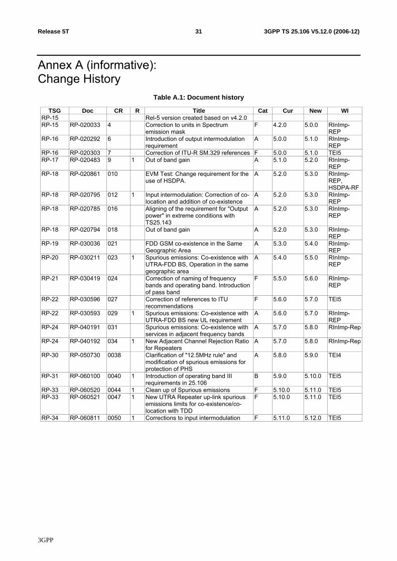
Annex A (informative): Change History
Table A.1: Document history
TSG Doc CR R Title Cat Cur New WI RP-15 Rel-5 version created based on v4.2.0 RP-15 RP-020033 4 Correction to units in Spectrum
emission mask F 4.2.0 5.0.0 RInImp-
REP RP-16 RP-020292 6 Introduction of output intermodulation
requirement A 5.0.0 5.1.0 RInImp-
REP RP-16 RP-020303 7 Correction of ITU-R SM.329 references F 5.0.0 5.1.0 TEI5 RP-17 RP-020483 9 1 Out of band gain A 5.1.0 5.2.0 RInImp-
REP RP-18 RP-020861 010 EVM Test: Change requirement for the
use of HSDPA. A 5.2.0 5.3.0 RInImp-
REP, HSDPA-RF
RP-18 RP-020795 012 1 Input intermodulation: Correction of co-location and addition of co-existence
A 5.2.0 5.3.0 RInImp-REP
RP-18 RP-020785 016 Aligning of the requirement for "Output power" in extreme conditions with TS25.143
A 5.2.0 5.3.0 RInImp-REP
RP-18 RP-020794 018 Out of band gain A 5.2.0 5.3.0 RInImp-REP
RP-19 RP-030036 021 FDD GSM co-existence in the Same Geographic Area
A 5.3.0 5.4.0 RInImp-REP
RP-20 RP-030211 023 1 Spurious emissions: Co-existence with UTRA-FDD BS, Operation in the same geographic area
A 5.4.0 5.5.0 RInImp-REP
RP-21 RP-030419 024 Correction of naming of frequency bands and operating band. Introduction of pass band
F 5.5.0 5.6.0 RInImp-REP
RP-22 RP-030596 027 Correction of references to ITU recommendations
F 5.6.0 5.7.0 TEI5
RP-22 RP-030593 029 1 Spurious emissions: Co-existence with UTRA-FDD BS new UL requirement
A 5.6.0 5.7.0 RInImp-REP
RP-24 RP-040191 031 Spurious emissions: Co-existence with services in adjacent frequency bands
A 5.7.0 5.8.0 RInImp-Rep
RP-24 RP-040192 034 1 New Adjacent Channel Rejection Ratio for Repeaters
A 5.7.0 5.8.0 RInImp-Rep
RP-30 RP-050730 0038 Clarification of "12.5MHz rule" and modification of spurious emissions for protection of PHS
A 5.8.0 5.9.0 TEI4
RP-31 RP-060100 0040 1 Introduction of operating band III requirements in 25.106
B 5.9.0 5.10.0 TEI5
RP-33 RP-060520 0044 1 Clean up of Spurious emissions F 5.10.0 5.11.0 TEI5 RP-33 RP-060521 0047 1 New UTRA Repeater up-link spurious
emissions limits for co-existence/co-location with TDD
F 5.10.0 5.11.0 TEI5
RP-34 RP-060811 0050 1 Corrections to input intermodulation F 5.11.0 5.12.0 TEI5
3GPP