utra fdd; physical layer procedures
TRANSCRIPT
3GPP RAN S1.14 V2.0.0 (1999-04)
UTRA FDD;Physical layer procedures
TSGRP#3 (99)237
3GPP TSG RAN WG1
3GPP RAN S1.14 V2.0.0 (1999-04)2
Reference<Workitem>
Keywords<keyword[, keyword]>
3GPP
Postal address
Office address
Internethttp://www.3gpp.org
Copyright Notification
Reproduction is only permitted for the purpose of standardization work undertaken within 3GPP.The copyright and the foregoing restrictions extend to reproduction in all media.
© 3GPP 1999.All rights reserved.
3GPP TSG RAN WG1
3GPP RAN S1.14 V2.0.0 (1999-04)3
Contents
Contents ............................................................................................................................................................. 3
Intellectual Property Rights ............................................................................................................................... 5
Foreword............................................................................................................................................................ 5
1 Scope ....................................................................................................................................................... 5
2 References ............................................................................................................................................... 5
3 Definitions, symbols and abbreviations .................................................................................................. 5
3.1 Definitions ............................................................................................................................................... 53.2 Symbols.............................................................................................................................................................. 53.3 Abbreviations..................................................................................................................................................... 6
4 Synchronisation procedures..................................................................................................................... 6
4.1 Cell search ............................................................................................................................................... 64.2 Primary CCPCH synchronisation....................................................................................................................... 74.3 Secondary CCPCH synchronisation................................................................................................................... 74.4 PRACH synchronisation .................................................................................................................................... 74.5 DPCCH/DPDCH synchronisation...................................................................................................................... 74.5.1 General ......................................................................................................................................................... 74.5.2 No existing uplink dedicated channel........................................................................................................... 74.5.3 With existing uplink dedicated channel........................................................................................................ 9
5 Power control......................................................................................................................................... 105.1 Uplink power control ....................................................................................................................................... 105.1.1 PRACH ...................................................................................................................................................... 105.1.2 DPCCH/DPDCH........................................................................................................................................ 105.1.2.1 General ................................................................................................................................................. 105.1.2.2 Ordinary transmit power control........................................................................................................... 105.1.2.2.1 General............................................................................................................................................ 105.1.2.2.2 Combining of TPC commands known to be the same..................................................................... 115.1.2.2.3 Combining of TPC commands not known to be the same............................................................... 115.1.2.2.3.1 General scheme ......................................................................................................................... 125.1.2.2.3.2 Example of the scheme.............................................................................................................. 125.2 Downlink power control .................................................................................................................................. 125.2.1 Primary CCPCH......................................................................................................................................... 125.2.2 Secondary CCPCH..................................................................................................................................... 125.2.3 DPCCH/DPDCH........................................................................................................................................ 125.2.3.1 General ................................................................................................................................................. 125.2.3.2 Ordinary transmit power control........................................................................................................... 125.2.3.3 Slow transmit power control ................................................................................................................. 145.2.3.4 Site selection diversity transmit power control ..................................................................................... 155.2.3.4.1 General............................................................................................................................................ 155.2.3.4.2 Initiation of SSDT........................................................................................................................... 155.2.3.4.3 Settings of temporary cell identification ......................................................................................... 155.2.3.4.3.1 Definition of temporary cell identification ................................................................................ 155.2.3.4.3.2 Assignment of ID to each cell.................................................................................................... 165.2.3.4.3.3 Notification of ID assignment change ....................................................................................... 165.2.3.4.4 TPC procedure in UE...................................................................................................................... 165.2.3.4.5 Selection of primary cell ................................................................................................................. 165.2.3.4.6 Delivery of primary cell ID ............................................................................................................. 165.2.3.4.7 TPC procedure in the network ........................................................................................................ 175.2.3.4.7.1 Management of multiple transmission power levels .................................................................. 175.2.3.4.7.2 Power setting of the downlink Dedicated Physical Channel...................................................... 175.2.3.4.8 Termination of SSDT...................................................................................................................... 18
3GPP TSG RAN WG1
3GPP RAN S1.14 V2.0.0 (1999-04)4
5.2.4 Power Control with DSCH....................................................................................................................................... 18
6 Random access procedure ..................................................................................................................... 18
7 Transmission stop and resumption control............................................................................................ 197.1 General............................................................................................................................................................. 197.2 Transmission stop control ................................................................................................................................ 207.2.1 Network control procedure......................................................................................................................... 207.2.2 UE control procedure ................................................................................................................................. 207.2.3 Illustration of network and UE procedures................................................................................................. 207.3 Transmission resumption control ..................................................................................................................... 217.3.1 Network control procedure......................................................................................................................... 217.3.2 UE control procedure ................................................................................................................................. 217.3.3 Illustration of network and UE procedures................................................................................................. 22
8 Feedback mode transmit diversity ......................................................................................................... 238.1 DPCH transmission scheme ............................................................................................................................. 238.2 Uplink signaling channel.................................................................................................................................. 238.3 Determination of feedback information ........................................................................................................... 258.4 Antenna verification......................................................................................................................................... 25
9 Reverse link synchronous transmission................................................................................................. 259.1 General............................................................................................................................................................. 259.2 Initial synchronisation...................................................................................................................................... 269.3 Tracking process .............................................................................................................................................. 269.4 Reference time ................................................................................................................................................. 26
Annex A (informative): Other procedures .................................................................................................. 27A.1 Paging procedure ............................................................................................................................................. 27A.1.1 Network operation...................................................................................................................................... 27A.1.2 UE operation .............................................................................................................................................. 27A.2 Forward link power control.............................................................................................................................. 28A.2.1 Forward link power control under hand-over mode ................................................................................... 28A.2.2 Forward link power control of dedicated physical channel ........................................................................ 29A.2.3 Forward link power control of dedicated physical channel in hand-over mode ......................................... 29
Annex X: Description to be study in WG2 .................................................................................................. 30X.1 Outer loop power control ................................................................................................................................. 30X.2 Access Control for Multi-rate and/or Multi-code Packet Data Transmission .................................................. 30
History ............................................................................................................................................................. 32
3GPP TSG RAN WG1
3GPP RAN S1.14 V2.0.0 (1999-04)5
Intellectual Property Rights< Editor’s note: To be filled in. >
ForewordThis specification has been produced within the Third Generation Partnership Project (3GPP), and has been elaboratedby the TSG RAN WG1 working group, as a part of the work in defining and describing Layer 1 of the Universal MobileTerrestrial Radio Access (UTRA).
This specification describes the physical layer procedures in UTRA/FDD.
1 ScopeThis document specifies and establishes the characteristics of the physicals layer procedures in the FDD mode of UTRA.
2 ReferencesThe following documents contain provisions which, through reference in this text, constitute provisions of the presentdocument.
• References are either specific (identified by date of publication, edition number, version number, etc.) ornon-specific.
• For a specific reference, subsequent revisions do not apply.
• For a non-specific reference, subsequent revisions do apply.
• A non-specific reference to an ETS shall also be taken to refer to later versions published as an EN with the samenumber.
[1] Reference 1
3 Definitions, symbols and abbreviations
3.1 Definitions For the purposes of the present document, the following definitions apply:
<defined term>: <definition>.
3.2 Symbols For the purposes of the present document, the following symbols apply:
<symbol> <Explanation>
3GPP TSG RAN WG1
3GPP RAN S1.14 V2.0.0 (1999-04)6
3.3 Abbreviations For the purposes of the present document, the following abbreviations apply:
BCH Broadcast Channel CCPCH Common Control Physical Channel DCH Dedicated Channel DPCCH Dedicated Physical Control Channel DPCH Dedicated Physical Channel DPDCH Dedicated Physical Data Channel FACH Forward Access Channel MUI Mobile User Identifier PCH Paging Channel PI Paging Indication PRACH Physical Random Access Channel RACH Random Access Channel SCH Synchronisation Channel SIR Signal-to-Interference Ratio SSDT Site Selection Diversity TPC TPC Transmit Power Control UE User Equipment
4 Synchronisation procedures
4.1 Cell search’“”During the cell search, the UE searches for a cell and determines the downlink scrambling code and framesynchronisation of that cell. The cell search is typically carried out in three steps:
Step 1: Slot synchronisation
During the first step of the cell search procedure the UE uses the SCH’s primary synchronisation code to acquire slotsynchronisation to a cell. This is typically done with a single matched filter (or any similar device) matched to theprimary synchronisation code which is common to all cells. The slot timing of the cell can be obtained by detectingpeaks in the matched filter output.
Step 2: Frame synchronisation and code-group identification
During the second step of the cell search procedure, the UE uses the SCH’s secondary synchronisation code to findframe synchronisation and identify the code group of the cell found in the first step. This is done by correlating thereceived signal with all possible secondary synchronisation code sequences, and identifying the maximum correlationvalue. Since the cyclic shifts of the sequences are unique the code group as well as the frame synchronisation isdetermined.
Step 3: Scrambling-code identification
During the third and last step of the cell search procedure, the UE determines the exact primary scrambling code used bythe found cell. The primary scrambling code is typically identified through symbol-by-symbol correlation over thePrimary CCPCH with all codes within the code group identified in the second step. After the primary scrambling codehas been identified, the Primary CCPCH can be detected, super-frame synchronisation can be acquired and the system-and cell specific BCH information can be read.
If the UE has received a priority list with information about which scrambling codes to search for, steps 2 and 3 abovecan be simplified.
3GPP TSG RAN WG1
3GPP RAN S1.14 V2.0.0 (1999-04)7
4.2 Primary CCPCH synchronisation< Editor’s note: The contents of this subclause comes from Volume 3 section 3.2.6.2.1. >
Synchronisation of the Primary CCPCHs is obtained during the cell search, see subclause 4.1 above. Framesynchronisation is obtained in step 2 of the cell search, and super-frame synchronisation is obtained by reading the SFNinformation on the BCH.
4.3 Secondary CCPCH synchronisation< Editor’s note: The contents of this subclause comes from Volume 3 section 3.2.6.2.2. >
Synchronisation of the Secondary CCPCHs can be obtained from the Primary CCPCH synchronisation and the timingoffset information TCPCH <ARIB terminology, to be confirmed> broadcast on the BCH. The frame timing and super-frame timing of the Secondary CCPCH is shifted by TCPCH from the timing of the Primary CCPCH.
4.4 PRACH synchronisation< Editor’s note: This needs to be co-ordinated with the random access description. Contents of this subclause comesfrom Volume 3 section 3.2.5.1 and XX.03 subclause 5.2.2.1.1. >
Transmission of random access bursts on the PRACH is done aligned with access slot times. The timing of the accessslots is derived from the received Primary CCPCH timing < Editor’s note: In ARIB it is offset from the SecondaryCCPCH. > The transmit timing of access slot n starts n×10/N ms after the frame boundary of the received PrimaryCCPCH, where n = 0, 1, …, N-1, and N is the number of access slots per 10 ms.
4.5 DPCCH/DPDCH synchronisation< Editor’s note: The contents of this subclause comes from Volume 3 section 3.2.6.2.3.2 and 3.2.6.6.1, but thepresentation of the material has been re-structured. >
4.5.1 General
The synchronisation of the dedicated physical channels can be divided into two cases:
- when a downlink dedicated physical channel and uplink dedicated physical channel shall be set up at the sametime;
- or when a downlink dedicated physical channel shall be set up and there already exist an uplink dedicatedphysical channel.
The two cases are described in subclauses 5.5.1 and 5.5.2 respectively.
4.5.2 No existing uplink dedicated channel
The assumption for this case is that a DPCCH/DPDCH pair shall be set up in both uplink and downlink, and that thereexist no uplink DPCCH/DPDCH already. This corresponds to the case when a dedicated physical channel is initially setup on a frequency.
< Editor’s note: The actual procedure below is for the time being copied directly from Volume 3 section3.2.6.2.3.2. Theterminology should be updated in accordance with the rest of the specification. The figure should also be updated. Thiswill be done in the next version of this document. The criteria for synchronisation cinfirmation should be consideredinformative, and should be moved to an informative annex.>
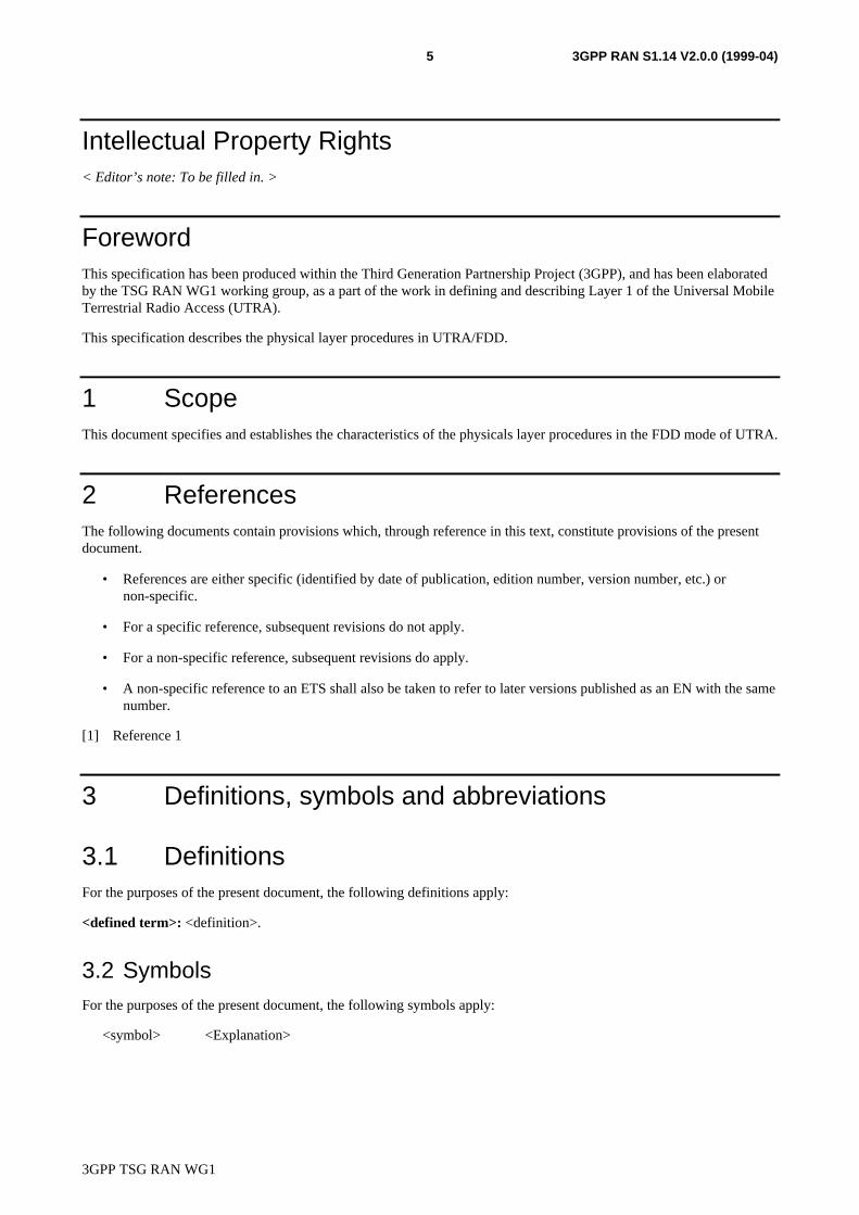
The outline of synchronization establishment procedures of the dedicated physical channel is described below. Thedetailed synchronization establishment process flow is shown in Figure 1.
3GPP TSG RAN WG1
3GPP RAN S1.14 V2.0.0 (1999-04)8
a) The network starts the transmission of downlink channels. The TPC commands transmitted by the networkfollows a predetermined pattern,< Editor’s note: What pattern? >. The DPDCH is transmitted only when thereis data to be transmitted to the UE.
b) The UE establishes downlink chip synchronization and frame synchronization based on the Primary CCPCHsynchronization timing and the frame offset group, slot offset group notified from the network. The framesynchronization shall be confirmed using the Frame Synchronization Word.
c) The UE starts the transmission of uplink channels at the frame timing delayed by the slot offset from thedownlink channel. The DPDCH is transmitted only when there is data to be transmitted to the network. Thetransmission power of uplink channels follows the TPC commands transmitted by the network. TPC commandstransmitted by the UE are based on downlink SIR measurements.
d) The network establishes uplink channel chip synchronization and frame synchronization based on the frameoffset group and slot offset group. Frame synchronization is confirmed if the output of the correlator using theframe synchronization word exceeds the predetermined threshold. The success of the frame synchronizationconfirmation is determined when the successive SR frame synchronization is confirmed. Otherwise, the framesynchronization confirmation failure is determined. Then this synchronisation status information is reported tothe upper layer.The transmission power of the downlink channels follow the TPC commands transmitted by theUE.
Start down link synchronization establishmentprocess.
UE Network
Start the transmission of down link channels.• TPC bits transmitted by network are
predetermined pattern.• Transmission of DATA field on DPDCH
depends on whether there is data to betransmitted to UE.
Establish chip synchronization and confirmframe synchronization.
Start the transmission of down link channels.• Transmission power of up link channel follow
the TPC bits transmitted by network.• TPC bits transmitted by UE are based on
down link Eb/Io measurement results.• Transmission of DATA field on DPDCH
depends on whether there is data to betransmitted to BTS. Establish chip synchronization and confirm
frame synchronization.
Start up link synchronization establishmentprocess.
Inform synchronization confirmation to upperlayer
Transmission power of down link channelfollow the TPC bits transmitted by UE.up link.
Figure 1: Synchronization Establishment Flow of Dedicated Channels
3GPP TSG RAN WG1
3GPP RAN S1.14 V2.0.0 (1999-04)9
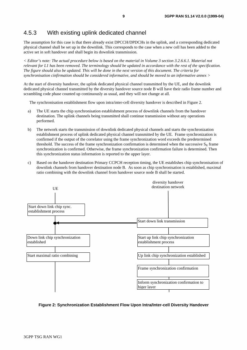
4.5.3 With existing uplink dedicated channel
The assumption for this case is that there already exist DPCCH/DPDCHs in the uplink, and a corresponding dedicatedphysical channel shall be set up in the downlink. This corresponds to the case when a new cell has been added to theactive set in soft handover and shall begin its downlink transmission.
< Editor’s note: The actual procedure below is based on the material in Volume 3 section 3.2.6.6.1. Material notrelevant for L1 has been removed. The terminology should be updated in accordance with the rest of the specification.The figure should also be updated. This will be done in the next version of this document. The criteria forsynchronisation cinfirmation should be considered informative, and should be moved to an informative annex >
At the start of diversity handover, the uplink dedicated physical channel transmitted by the UE, and the downlinkdedicated physical channel transmitted by the diversity handover source node B will have their radio frame number andscrambling code phase counted up continuously as usual, and they will not change at all.
The synchronisation establishment flow upon intra/inter-cell diversity handover is described in Figure 2.
a) The UE starts the chip synchronisation establishment process of downlink channels from the handoverdestination. The uplink channels being transmitted shall continue transmission without any operationsperformed.
b) The network starts the transmission of downlink dedicated physical channels and starts the synchronizationestablishment process of uplink dedicated physical channel transmitted by the UE. Frame synchronization isconfirmed if the output of the correlator using the frame synchronization word exceeds the predeterminedthreshold. The success of the frame synchronization confirmation is determined when the successive SR framesynchronization is confirmed. Otherwise, the frame synchronization confirmation failure is determined. Thenthis synchronization status information is reported to the upper layer.
c) Based on the handover destination Primary CCPCH reception timing, the UE establishes chip synchronisation ofdownlink channels from handover destination node B. As soon as chip synchronisation is established, maximalratio combining with the downlink channel from handover source node B shall be started.
UE
diversity handoverdestination network
Start down link chip sync.establishment process
Start down link transmission
Down link chip synchronizationestablished
Start maximal ratio combining
Start up link chip synchronizationestablishment process
Up link chip synchronization established
Frame synchronization confirmation
Inform synchronization confirmation tohiger layer
Figure 2: Synchronization Establishment Flow Upon Intra/Inter-cell Diversity Handover
3GPP TSG RAN WG1
3GPP RAN S1.14 V2.0.0 (1999-04)10
5 Power control
5.1 Uplink power control
5.1.1 PRACH
< Editor’s note: This clause describes open loop power control scheme for PRACH. To be confirmed appropriate Sdocuments for open loop power control, and moved this description to the appropriate S document.>
• The transmitter power of UE shall be calculated by following equation:PRACH = LPerch + IBTS + Constant valuewhere,PRACH: transmitter power level in dBm,LPearch: measured path loss in dB,IBTS: interference signal power level at BTS in dBm, which is broadcasted on BCH,Constant value: This value shall be designated via Layer 3 message (operator matter).
5.1.2 DPCCH/DPDCH
5.1.2.1 General
’The uplink transmit power control procedure controls simultaneously the power of a DPCCH and its correspondingDPDCHs. The power control loop adjusts the power of the DPCCH and DPDCHs with the same amount. The relativetransmit power offset between DPCCH and DPDCHs is determined by the network and signalled to the UE using higherlayer signalling.
5.1.2.2 Ordinary transmit power control
5.1.2.2.1 General
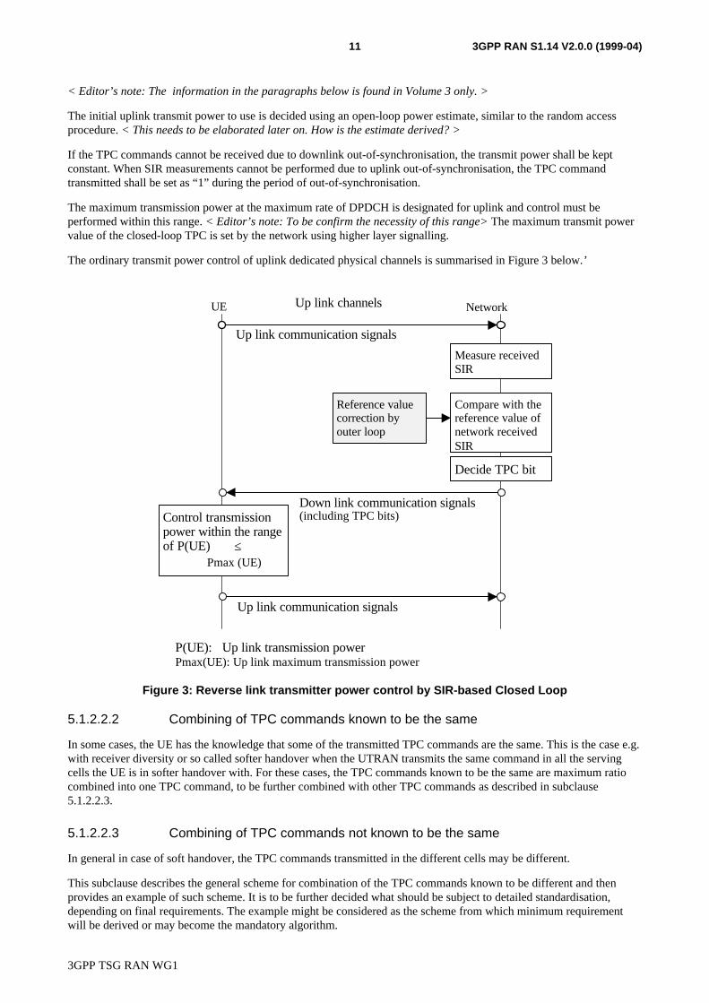
The uplink closed-loop power control adjusts the UE transmit power in order to keep the received uplink signal-to-interference ratio (SIR) at a given SIR target, SIRtarget. An higher layer outer loop adjusts SIRtarget independently for eachcell in the active set.
The serving cells (cells in the active set) should estimate the received uplink DPCCH power after RAKE combining ofthe connection to be power controlled. Simultaneously, the serving cells should estimate the total uplink receivedinterference in the current frequency band and generate a SIR estimate SIRest. The serving cells then generates TPCcommands and transmits the commands once per 0.625 ms slot according to the following rule: if SIRest > SIRtarget thenthe TPC command to transmit is “0”, while if SIRest < SIRtarget then the TPC command to transmit is “1”.
If multiple TPC commands are received, then upon reception of these TPC commands, the UE combines the receivedcommands into a single TPC command, TPC_cmd. The combination process depends on whether the transmitted TPCcommands are known to be the same or not. The combination process for each of these two cases is described insubclauses 5.1.2.2.2 and 5.1.2.2.3 respectively.
After calculation of the combined TPC command TPC_cmd, the UE then adjusts the transmit power of the uplinkdedicated physical channels with a step of ∆TPC dB according to the TPC command. If TPC_cmd equals 1 then thetransmit power of the uplink DPCCH and uplink DPDCHs shall be increased by ∆TPC dB. If TPC_cmd equals 0 then thetransmit power of the uplink DPCCH and uplink DPDCHs shall be decreased by ∆TPC dB.
< Editor’s note: In Volume 3, it is stated that the time for changing transmit power shall be immediately before the pilotblock. This is linked to slot structure (ad hoc 7), and could be described in S1.11. >
The step size ∆TPC is a parameter that may differ between different cells, in the region 0,25 – 1,5 dB. <Editor’s note: InVolume 3 ∆TPC is fixed to 1 dB, this is discussed by the power control ad hoc. > In the event different step sizes are usedin the different serving cells, then the transmit power change should take into account the TPC command obtained bycombining individual commands and the different step sizes, and should be one of the allowed step sizes (FFS).
3GPP TSG RAN WG1
3GPP RAN S1.14 V2.0.0 (1999-04)11
< Editor’s note: The information in the paragraphs below is found in Volume 3 only. >
The initial uplink transmit power to use is decided using an open-loop power estimate, similar to the random accessprocedure. < This needs to be elaborated later on. How is the estimate derived? >
If the TPC commands cannot be received due to downlink out-of-synchronisation, the transmit power shall be keptconstant. When SIR measurements cannot be performed due to uplink out-of-synchronisation, the TPC commandtransmitted shall be set as “1” during the period of out-of-synchronisation.
The maximum transmission power at the maximum rate of DPDCH is designated for uplink and control must beperformed within this range. < Editor’s note: To be confirm the necessity of this range> The maximum transmit powervalue of the closed-loop TPC is set by the network using higher layer signalling.
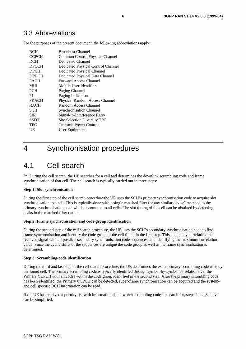
The ordinary transmit power control of uplink dedicated physical channels is summarised in Figure 3 below.’
Measure receivedSIR
Compare with thereference value ofnetwork receivedSIR
Decide TPC bit
Control transmissionpower within the rangeof P(UE) ≤
Pmax (UE)
Reference valuecorrection byouter loop
Up link channelsUE Network
Up link communication signals
Down link communication signals(including TPC bits)
Up link communication signals
P(UE): Up link transmission powerPmax(UE): Up link maximum transmission power
Figure 3: Reverse link transmitter power control by SIR-based Closed Loop
5.1.2.2.2 Combining of TPC commands known to be the same
In some cases, the UE has the knowledge that some of the transmitted TPC commands are the same. This is the case e.g.with receiver diversity or so called softer handover when the UTRAN transmits the same command in all the servingcells the UE is in softer handover with. For these cases, the TPC commands known to be the same are maximum ratiocombined into one TPC command, to be further combined with other TPC commands as described in subclause5.1.2.2.3.
5.1.2.2.3 Combining of TPC commands not known to be the same
In general in case of soft handover, the TPC commands transmitted in the different cells may be different.
This subclause describes the general scheme for combination of the TPC commands known to be different and thenprovides an example of such scheme. It is to be further decided what should be subject to detailed standardisation,depending on final requirements. The example might be considered as the scheme from which minimum requirementwill be derived or may become the mandatory algorithm.
3GPP TSG RAN WG1
3GPP RAN S1.14 V2.0.0 (1999-04)12
5.1.2.2.3.1 General scheme
First, the UE shall estimate the signal-to-interference ratio PC_SIRi on each of the power control command TPCi, wherei = 1, 2, …, N and N is the number of TPC commands known to be different, that may be the results of a first phase ofcombination according to subclause 5.1.2.2.3.
Then the UE assigns to each of the TPCi command a reliability figure Wi, where Wi is a function β of PC_SIRi,
Wi = β(PC_SIRi). Finally, the UE derives a combined TPC command, TPC_cmd, as a function γ of all the N powercontrol commands TPCi and reliability estimates Wi:
TPC_cmd = γ (W1, W2, … WN, TPC1, TPC2, …, TPCN), where TPC_cmd can take the values 0 or 1.
5.1.2.2.3.2 Example of the scheme
A particular example of the scheme is obtained when using the following definition of the functions β and γ:
For ββ: the reliability figure Wi is set to 0 if PC_SIRi < PC_thr, otherwise Wi is set to 1. This means that the powercontrol command is assumed unreliable if the signal-to-interference ratio of the TPC commands is lower than aminimum value PC_thr.
For γγ: if there is at least one TPCi command, for which Wi = 1 and TPCi = 0, then TPC_cmd is set to 0, otherwiseTPC_cmd is set to 1. Such a function γ means that the power is decreased if at least one cell for which the reliabilitycriterion is satisfied asks for a power decrease.
5.2 Downlink power control
5.2.1 Primary CCPCH
’’The Primary CCPCH transmit power can vary on a slow basis, i.e. the power is constant over many frames. Thetransmit power is determined by the network and signalled on the BCH.
5.2.2 Secondary CCPCH
’The Secondary CCPCH transmit power is set by the network, and may vary.
5.2.3 DPCCH/DPDCH
5.2.3.1 General
The downlink transmit power control procedure controls simultaneously the power of a DPCCH and its correspondingDPDCHs. The power control loop adjusts the power of the DPCCH and DPDCHs with the same amount, i.e. the relativepower difference between the DPCCH and DPDCHs is not changed.
The relative transmit power offset between DPCCH fields and DPDCHs is determined by the network and signalled tothe UE using higher layer signalling. The TFCI, TPC and pilot fields of the DPCCH are offset relative to the DPDCHspower by PO1, PO2 and PO3 dB respectively. < Editor’s note: The range and need for signaling with power offsets isFFS.>5.2.3.2 Ordinary transmit power control
The downlink closed-loop power control adjusts the network transmit power in order to keep the received downlink SIRat a given SIR target, SIRtarget. An higher layer outer loop adjusts SIRtarget independently for each connection.
The UE should estimate the received downlink DPCCH/DPDCH power after RAKE combining, including diversitycombining, of the connection to be power controlled. Simultaneously, the UE should estimate the received interference.’“” The obtained SIR estimate SIRest is then used by the UE to generate TPC commands according to the following rule:if SIRest > SIRtarget then the TPC command to transmit is “0”, requesting a transmit power decrease, while if SIRest <SIRtarget then the TPC command to transmit is “1”, requesting a transmit power increase.
3GPP TSG RAN WG1
3GPP RAN S1.14 V2.0.0 (1999-04)13
< Editor’s note: How the SIR estimate should be derived is to be specified, in particular how it should be done for thecase with power offsets on the DPCCH. >
The TPC command generated is transmitted in the first available TPC field in the uplink DPCCH.
< Editor’s note: In Volume 3, the behaviour of the network is only given as examples. This leaves full freedom for thenetwork to decide how to respond to the TPC commands received. However, in XX.07 more information about thenetworks behaviour is given: “Upon the reception of a TPC command, the network should adjust the transmit power inthe given direction with a step of ∆TPC dB. The step size ∆TPC is a parameter that may differ between different cells, inthe range 0,25 – 1,5 dB.”. It is the view of the editor that the implementation of the network behaviour is not subject tostandardisation. To be confirmed. >
’When SIR measurements cannot be performed due to downlink out-of-synchronisation, the TPC command transmittedshall be set as “1” during the period of out-of-synchronisation.
< Editor’s note: In Volume 3 it is also described how the power should be controlled during link set-up. This shouldprobably be described in the synchronisation clause, so that the information is not repeated in several places. >
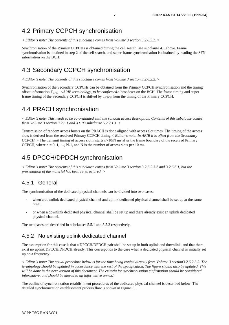
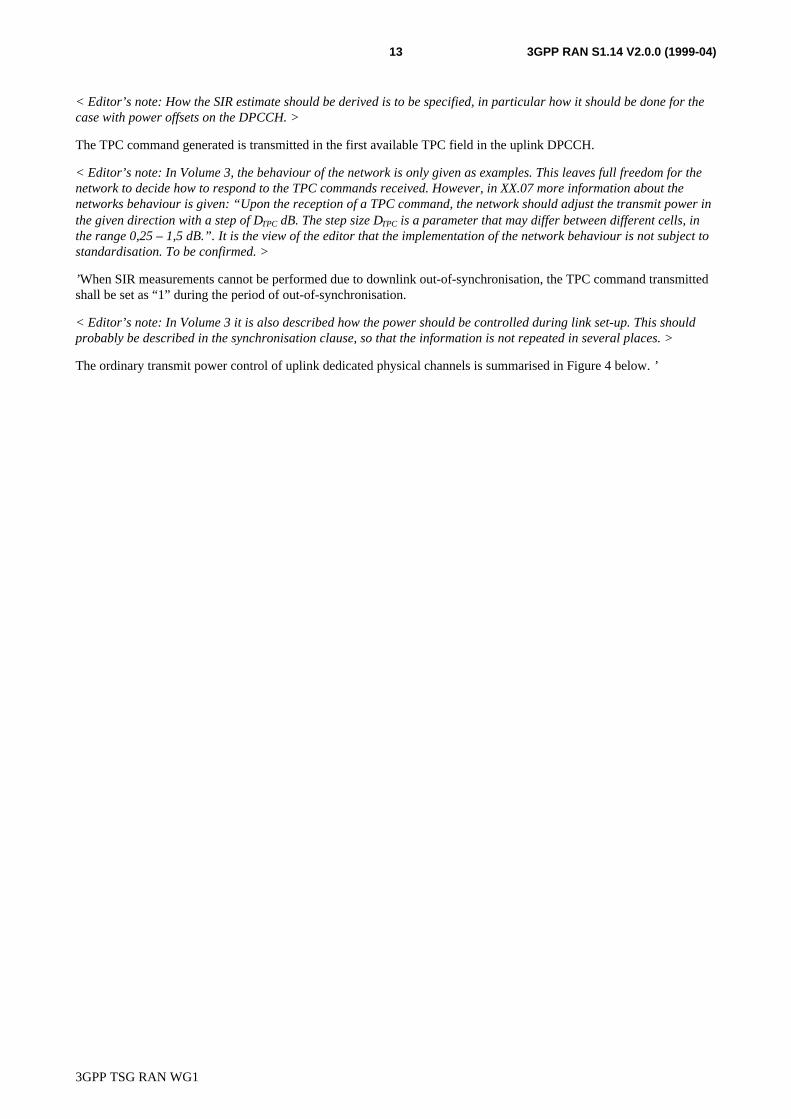
The ordinary transmit power control of uplink dedicated physical channels is summarised in Figure 4 below. ’
3GPP TSG RAN WG1
3GPP RAN S1.14 V2.0.0 (1999-04)14
Step 2:
Step 3:
Measure receivedSIR
Compare with thereference value ofUE received SIR
Decide TPC bit
Control transmission powerwithin the range ofPmin(netwok) ≤ P(network)≤ Pmax (network)
Reference valuecorrection byouter loop
Forward link channels
BTS MS
Down link communication signals
Up link communication signals(including TPC bits)
Down link communication signals
P(network): Down link transmission powerPmax(network): Downlink maximum transmission powerPmin(network): Downlink minimum transmission power
Step 1:Determine the initialtransmission power
Establish down linksynchronization
Start transmission
Start transmission
Establish up linksynchronization
Figure 4: Forward link transmitter power control
5.2.3.3 Slow transmit power control
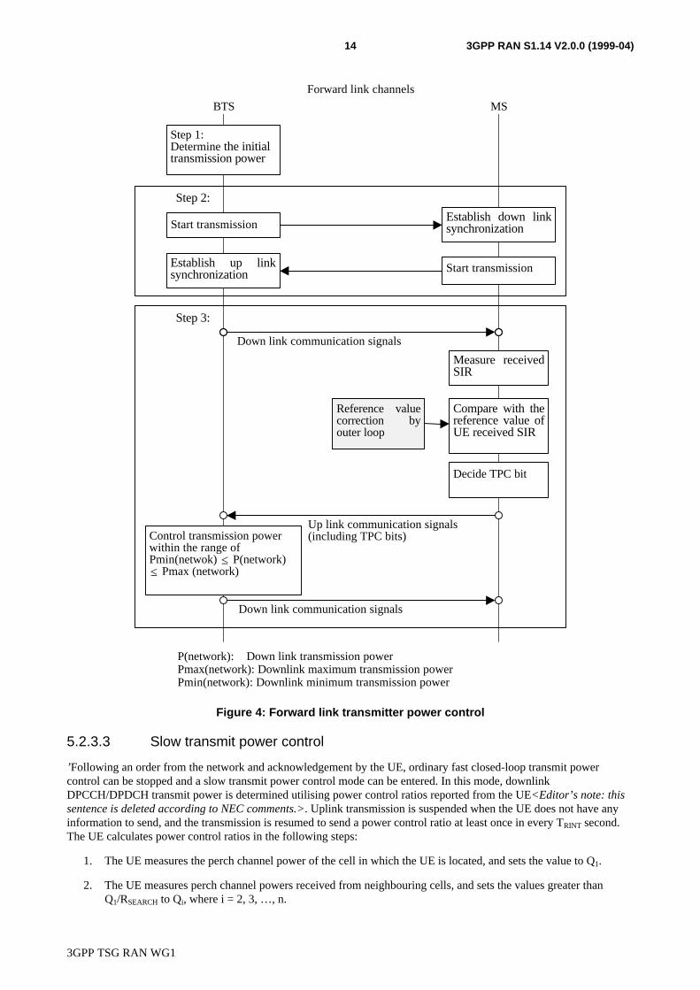
’Following an order from the network and acknowledgement by the UE, ordinary fast closed-loop transmit powercontrol can be stopped and a slow transmit power control mode can be entered. In this mode, downlinkDPCCH/DPDCH transmit power is determined utilising power control ratios reported from the UE<Editor’s note: thissentence is deleted according to NEC comments.>. Uplink transmission is suspended when the UE does not have anyinformation to send, and the transmission is resumed to send a power control ratio at least once in every TRINT second.The UE calculates power control ratios in the following steps:
1. The UE measures the perch channel power of the cell in which the UE is located, and sets the value to Q1.
2. The UE measures perch channel powers received from neighbouring cells, and sets the values greater thanQ1/RSEARCH to Qi, where i = 2, 3, …, n.
3GPP TSG RAN WG1
3GPP RAN S1.14 V2.0.0 (1999-04)15
3. The UE sets the power control ratio to (Q1 + Q2 + … + Qn)/Q1.
All TPC bits in the uplink DPCCH are used to send power control ratios. One power control ratio is sent per frame, i.e.32 TPC bits are used to carry the power control ratio. The bi-orthogonal (32,6) code described in subclause 6.3.1 is usedfor the encoding. Code word (-1)n C5,m corresponds to (0,5m + 0,25n) dB where m = 0, 1, 2, …, 31 and n = 0, 1.
Following an order from the network, the slow transmit power control is stopped and ordinary fast closed-loop transmitpower control is started. The parameters TRINT and RSEARCH are set using higher layer signalling.
5.2.3.4 Site selection diversity transmit power control
< Editor’s note: In general, the text describing SSDT should be checked to identify L1 and L23 issues separately. Somecontents should perhaps be moved to WG2 documentation. The text could also be made more specification-like. For thetime being the text is kept with some cosmetic and language related changes. >
5.2.3.4.1 General
Site selection diversity transmit power control (SSDT) is an optional macro diversity method in soft handover mode.
Operation is summarised as follows. The UE selects one of the cells from its active set to be ‘primary’, all other cells areclassed as ‘non primary’. The main objective is to transmit on the downlink from the best cell, thus reducing theinterference caused by multiple transmissions in a soft handover mode. A second objective is to achieve fast siteselection without network intervention, thus maintaining the advantage of the soft handover. In order to select a primarycell, each cell is assigned a temporary identification and UE periodically informs a primary cell identification to theconnecting cells. The non-primary cells selected by UE switch off the transmission power. The primary cell identitycode is delivered via vacant uplink TPC bits prepared by the puncture method described in subclause 5.2.3.4.6.
5.2.3.4.2 Initiation of SSDT
The SSDT is initiated by the network, based on the soft handover active cell set. The cell and UE are subsequentlyinformed by the network that the SSDT option has been activated during the current soft handover period. Otherwise,TPC is operated in the ordinary mode, i.e. each cell controls its power in accordance with an uplink TPC command bythe way described in 5.2.3.2. The temporary cell identification assignment (i.e. ID code assignment) is based on theorder of active set which is communicated to all the active cells and the UE.
A cell receiving the active list is capable of recognising its entry position in the list from which it can determine its ownID code. Similarly, UE upon receiving the active list can determine the ID code of each of the active cells according tothe order of the cell entries in the list. Therefore the network and UE has the same association between the ID codes andcells. After the activation of the SSDT and the subsequent UE acknowledgements, the UE starts to send the “primary”cell ID code, described in the following subclauses. Following a successful activation of SSDT and reception of the UEacknowledgement, the active cells start detecting the “primary” cell ID information.
5.2.3.4.3 Settings of temporary cell identification
Each cell is given a temporary identification during SSDT and the identification is utilised as site selection signal. In thefollowing, the temporary identification is referred to as “ID”.
5.2.3.4.3.1 Definition of temporary cell identification
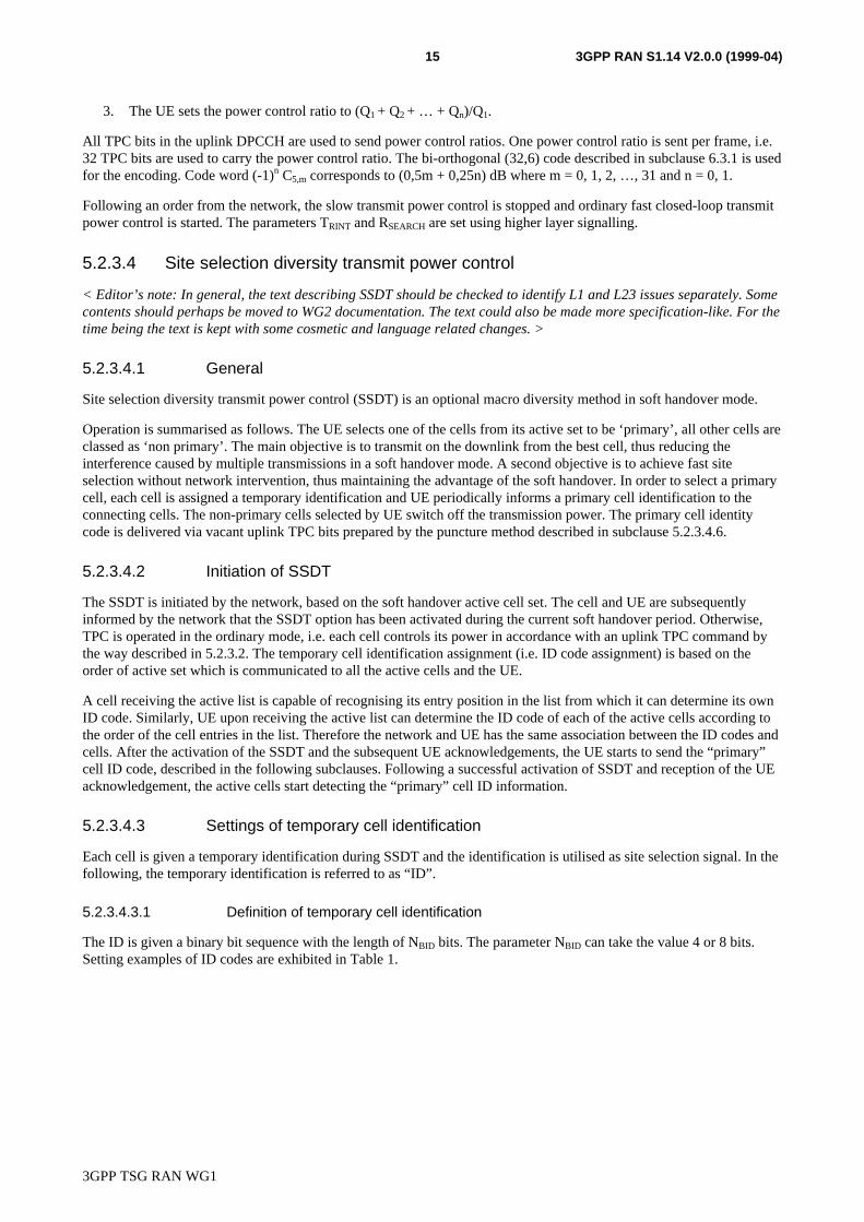
The ID is given a binary bit sequence with the length of NBID bits. The parameter NBID can take the value 4 or 8 bits.Setting examples of ID codes are exhibited in Table 1.
3GPP TSG RAN WG1
3GPP RAN S1.14 V2.0.0 (1999-04)16
Table 1: Setting examples of ID codes
ID codeID label NBID =8 NBID =4
a 00000000 0000b 11111111 1111c 00001111 0011d 11110000 1100e 00111100 0110f 11000011 1001
5.2.3.4.3.2 Assignment of ID to each cell
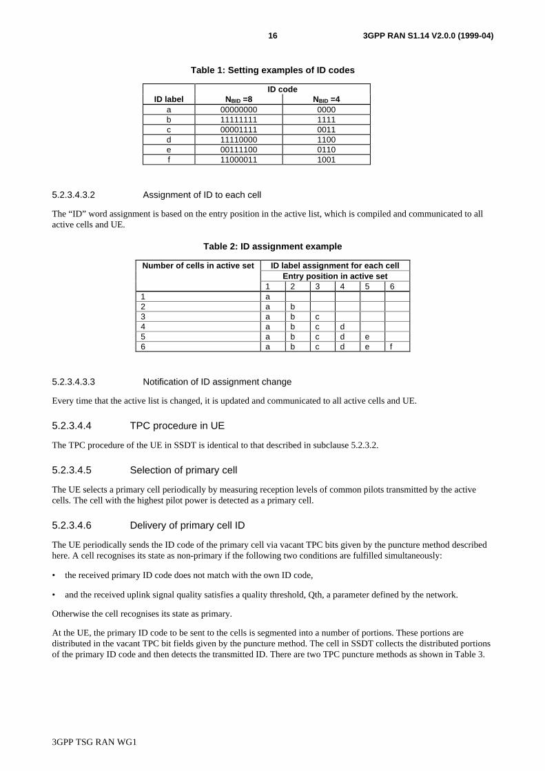
The “ID” word assignment is based on the entry position in the active list, which is compiled and communicated to allactive cells and UE.
Table 2: ID assignment example
Number of cells in active set ID label assignment for each cellEntry position in active set
1 2 3 4 5 61 a2 a b3 a b c4 a b c d5 a b c d e6 a b c d e f
5.2.3.4.3.3 Notification of ID assignment change
Every time that the active list is changed, it is updated and communicated to all active cells and UE.
5.2.3.4.4 TPC procedure in UE
The TPC procedure of the UE in SSDT is identical to that described in subclause 5.2.3.2.
5.2.3.4.5 Selection of primary cell
The UE selects a primary cell periodically by measuring reception levels of common pilots transmitted by the activecells. The cell with the highest pilot power is detected as a primary cell.
5.2.3.4.6 Delivery of primary cell ID
The UE periodically sends the ID code of the primary cell via vacant TPC bits given by the puncture method describedhere. A cell recognises its state as non-primary if the following two conditions are fulfilled simultaneously:
• the received primary ID code does not match with the own ID code,
• and the received uplink signal quality satisfies a quality threshold, Qth, a parameter defined by the network.
Otherwise the cell recognises its state as primary.
At the UE, the primary ID code to be sent to the cells is segmented into a number of portions. These portions aredistributed in the vacant TPC bit fields given by the puncture method. The cell in SSDT collects the distributed portionsof the primary ID code and then detects the transmitted ID. There are two TPC puncture methods as shown in Table 3.
3GPP TSG RAN WG1
3GPP RAN S1.14 V2.0.0 (1999-04)17
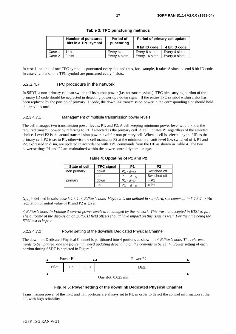
Table 3: TPC puncturing methods
Number of puncturedbits in a TPC symbol
Period ofpuncturing
Period of primary cell update
8 bit ID code 4 bit ID codeCase 1 1 bit Every slot Every 8 slots Every 4 slotsCase 2 2 bits Every 4 slots Every 16 slots Every 8 slots
In case 1, one bit of one TPC symbol is punctured every slot and thus, for example, it takes 8 slots to send 8 bit ID code.In case 2, 2 bits of one TPC symbol are punctured every 4 slots.
5.2.3.4.7 TPC procedure in the network
In SSDT, a non-primary cell can switch off its output power (i.e. no transmissions). TPC bits carrying portion of theprimary ID code should be neglected in detecting power up / down signal. If the entire TPC symbol within a slot hasbeen replaced by the portion of primary ID code, the downlink transmission power in the corresponding slot should holdthe previous one.
5.2.3.4.7.1 Management of multiple transmission power levels
The cell manages two transmission power levels, P1, and P2. A cell keeping minimum power level would know therequired transmit power by referring to P1 if selected as the primary cell. A cell updates P1 regardless of the selectedchoice. Level P2 is the actual transmission power level for non-primary cell. When a cell is selected by the UE as theprimary cell, P2 is set to P1, otherwise the cell maintains P2 at the minimum transmit level (i.e. switched off). P1 andP2, expressed in dBm, are updated in accordance with TPC commands from the UE as shown in Table 4. The twopower settings P1 and P2 are maintained within the power control dynamic range.
Table 4: Updating of P1 and P2
State of cell TPC signal P1 P2non primary down P1 - ∆TPC Switched off
up P1 + ∆TPC Switched offprimary down P1 - ∆TPC = P1
up P1 + ∆TPC = P1
∆TPC is defined in subclause 5.2.3.2. < Editor’s note: Maybe it is not defined in standard, see comment in 5.2.3.2. > Noregulation of initial value of P1and P2 is given.
< Editor’s note: In Volume 3 several power levels are managed by the network. This was not accepted in ETSI so far.The outcome of the discussion on DPCCH field offsets should have impact on this issue as well. For the time being theETSI text is kept.>
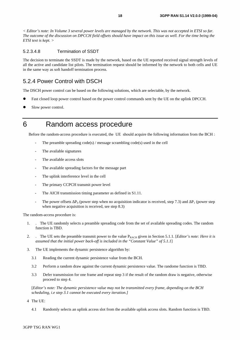
5.2.3.4.7.2 Power setting of the downlink Dedicated Physical Channel
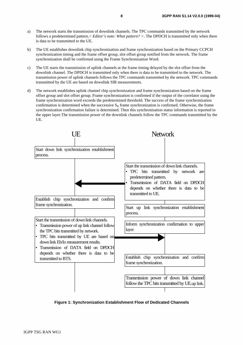
The downlink Dedicated Physical Channel is partitioned into 4 portions as shown in < Editor’s note: The referenceneeds to be updated, and the figure may need updating depending on the contents in S1.11. >. Power setting of eachportion during SSDT is depicted in Figure 5.
TPC
One slot, 0.625 ms
Pilot Data
Power P1 Power P2
TFCI
Figure 5: Power setting of the downlink Dedicated Physical Channel
Transmission power of the TPC and TFI portions are always set to P1, in order to detect the control information at theUE with high reliability.
3GPP TSG RAN WG1
3GPP RAN S1.14 V2.0.0 (1999-04)18
< Editor’s note: In Volume 3 several power levels are managed by the network. This was not accepted in ETSI so far.The outcome of the discussion on DPCCH field offsets should have impact on this issue as well. For the time being theETSI text is kept. >
5.2.3.4.8 Termination of SSDT
The decision to terminate the SSDT is made by the network, based on the UE reported received signal strength levels ofall the active and candidate list pilots. The termination request should be informed by the network to both cells and UEin the same way as soft handoff termination process.
5.2.4 Power Control with DSCH
The DSCH power control can be based on the following solutions, which are selectable, by the network.
l Fast closed loop power control based on the power control commands sent by the UE on the uplink DPCCH.
l Slow power control.
6 Random access procedureBefore the random-access procedure is executed, the UE should acquire the following information from the BCH :
- The preamble spreading code(s) / message scrambling code(s) used in the cell
- The available signatures
- The available access slots
- The available spreading factors for the message part
- The uplink interference level in the cell
- The primary CCPCH transmit power level
- The AICH transmission timing parameter as defined in S1.11.
- The power offsets ∆P0 (power step when no acquisition indicator is received, step 7.3) and ∆P1 (power stepwhen negative acquisition is received, see step 8.3)
The random-access procedure is:
1. . The UE randomly selects a preamble spreading code from the set of available spreading codes. The randomfunction is TBD.
2. . The UE sets the preamble transmit power to the value PRACH given in Section 5.1.1. [Editor’s note: Here it isassumed that the initial power back-off is included in the “Constant Value” of 5.1.1]
3. The UE implements the dynamic persistence algorithm by:
3.1 Reading the current dynamic persistence value from the BCH.
3.2 Perform a random draw against the current dynamic persistence value. The randome function is TBD.
3.3 Defer transmission for one frame and repeat step 3 if the result of the random draw is negative, otherwiseproceed to step 4.
[Editor’s note: The dynamic persistence value may not be transmitted every frame, depending on the BCHscheduling, i.e step 3.1 cannot be executed every iteration.]
4 The UE:
4.1 Randomly selects an uplink access slot from the available uplink access slots. Random function is TBD.
3GPP TSG RAN WG1
3GPP RAN S1.14 V2.0.0 (1999-04)19
4.2 Randomly selects a signature from the available signatures. Random function is TBD.
5 5. The UE sets the Preamble Retransmission Counter to Preamble_Retrans_Max (value TBD).
6 The UE transmits its preamble using the selected uplink access slot, signature, and preamble transmission power..
7 If the UE does not detect an acquisition indicator with the selected signature in the downlink access slotcorresponding to the selected uplink access slot, the UE:
7.1 Selects a new uplink access slot, , This new access slot must be one of the available access slots. There mustbe also a distance of three or four access slots from the uplink access slot in which the last preamble wastransmitted depending on the AICH transmission timing parameter. The selection scheme of this new accessslot is TBD.
7.2 Randomly selects a new signature from the available signatures. Random function is TBD.
7.3 Increases the preamble transmission power with the specified offset ∆P0.
7.4 Decrease the Preamble Retransmission Counter by one.
7.5 If the Preamble Retransmission Counter > 0, the UE repeats from step 6 otherwise an error indication ispassed to the higher layers and the random-access procedure is exited.
8. If the UE detects a negative acquisition indicator with the selected signature in the downlink access slotcorresponding to the selected uplink access slot, the UE:
8.1 Selects a new uplink access slot as in 7.1
8.2 Randomly selects a new signature from the available signatures. Random function is TBD.
8.3 Modifies the preamble transmission power with the specified offset ∆P1.
[Editor’s note: Note clear if the Preamble Retransmission Counter should be decremented and tested in this case]
8.4 Reats from step 6
9. The UE transmits its random access message three or four uplink access slots after the uplink access slot of thelast transmitted preamble depending on the AICH transmission timing parameter…
10. A indication of successful random-accces transmission is passed to the higher layers.
Dynamic persistence is provided for managing interference and minimising delay by controlling access to the RACHchannel. The system will publish a dynamic persistence value on the BCH, the value of which is dependent on theestimated backlog of users in the system. �
7 Transmission stop and resumption control< Editor’s note: This control schem is under discusion in ad hoc 14.>
7.1 General’On dedicated physical channels, when no higher layer data exist to transmit, the DPDCH is empty and is nottransmitted. In order to save channel capacity, under some conditions the transmission of the DPCCH can also bestopped. Similarly, conditions are also defined for how the transmission of DPCCH/DPDCH is resumed.
< Editor’s note: From Volume 3 figure 3.2.6-16 it seems that the transmission stop scheme is only applicable when theother link do not transmit a DPDCH, while this is not explained in the text. Clarification is needed on this point. >
3GPP TSG RAN WG1
3GPP RAN S1.14 V2.0.0 (1999-04)20
7.2 Transmission stop control
7.2.1 Network control procedure
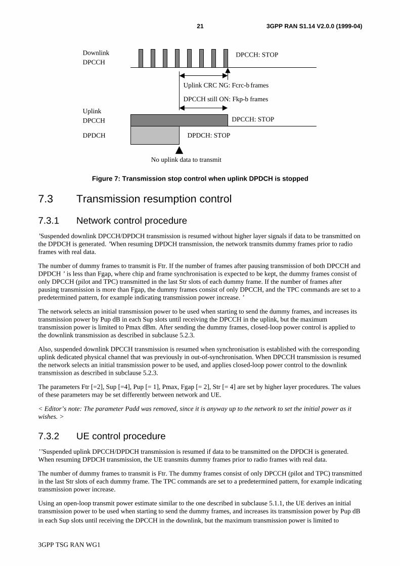
’The necessity of downlink DPCCH/DPDCH transmission is judged in each radio frame. When the DPDCH is stopped,i.e. there is no data to transmit on the DPDCH, the network continues to transmit the DPCCH until both
Figure 1999 Fkp-f radio frames have passed after the DPDCH transmission was stopped,
- and Fcrc-b radio frames are detected consecutively with no correct CRC in uplink,
when the DPCCH transmission is stopped as well.
The parameters Fkp-f [= 2] and Fcrc-b [= 2] are set by higher layer procedures.
7.2.2 UE control procedure
’The necessity of uplink DPCCH/DPDCH transmission is judged in each radio frame. When the DPDCH is stopped, i.e.there is no data to transmit on the DPDCH, the UE continues to transmit the DPCCH until both
Figure 1999 Fkp-b radio frames have passed after the DPDCH transmission was stopped,
- and the downlink is detected to be out-of-synchronisation,
when the DPCCH transmission is stopped as well.
The parameter Fkp-b [= 2] is set by higher layer procedures.
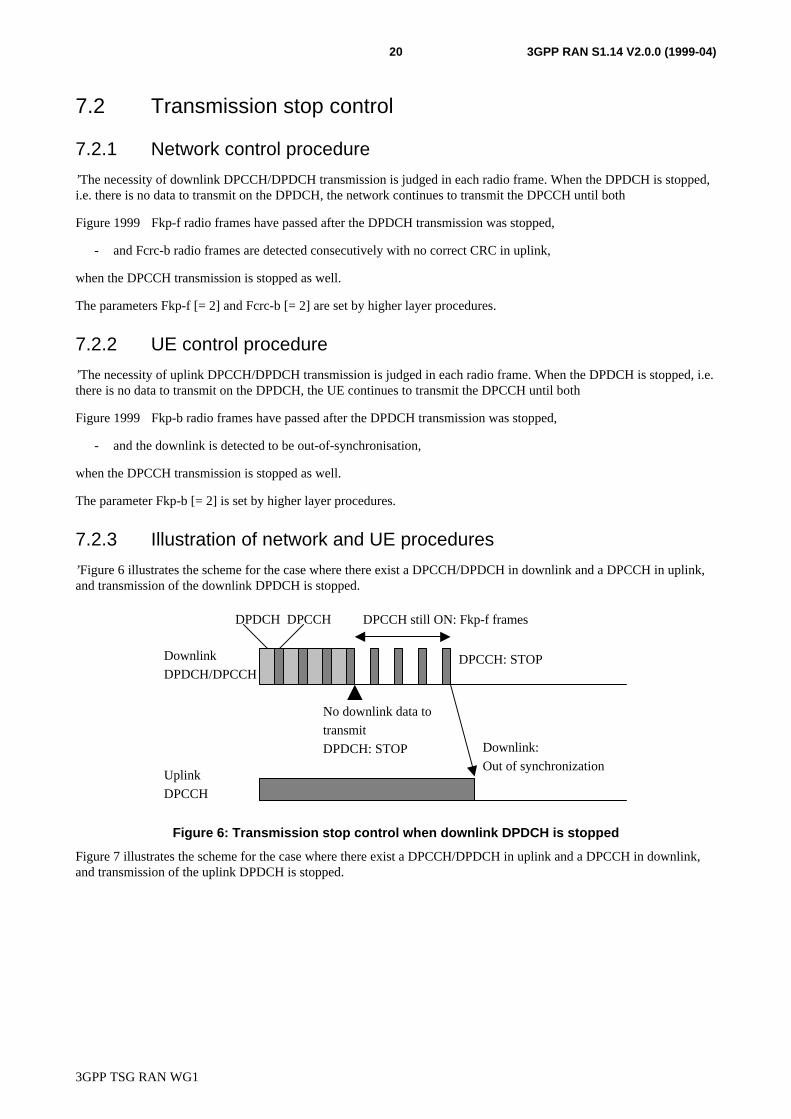
7.2.3 Illustration of network and UE procedures
’Figure 6 illustrates the scheme for the case where there exist a DPCCH/DPDCH in downlink and a DPCCH in uplink,and transmission of the downlink DPDCH is stopped.
Downlink
DPDCH/DPCCH
Uplink
DPCCH
No downlink data to
transmit
DPDCH: STOP
DPCCH still ON: Fkp-f frames
Downlink:
Out of synchronization
DPDCH DPCCH
DPCCH: STOP
Figure 6: Transmission stop control when downlink DPDCH is stopped
Figure 7 illustrates the scheme for the case where there exist a DPCCH/DPDCH in uplink and a DPCCH in downlink,and transmission of the uplink DPDCH is stopped.
3GPP TSG RAN WG1
3GPP RAN S1.14 V2.0.0 (1999-04)21
Downlink
DPCCH
Uplink
DPCCH
DPDCH
No uplink data to transmit
DPCCH still ON: Fkp-b frames
Uplink CRC NG: Fcrc-b frames
DPCCH: STOP
DPCCH: STOP
DPDCH: STOP
Figure 7: Transmission stop control when uplink DPDCH is stopped
7.3 Transmission resumption control
7.3.1 Network control procedure
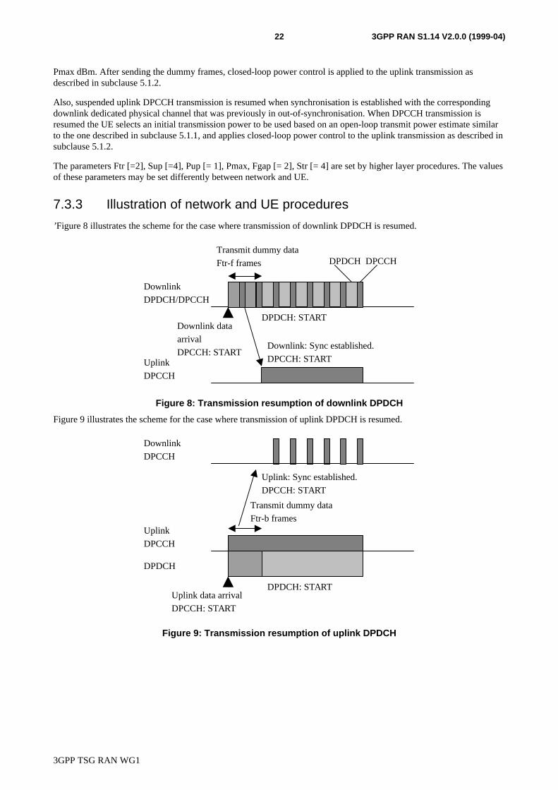
’Suspended downlink DPCCH/DPDCH transmission is resumed without higher layer signals if data to be transmitted onthe DPDCH is generated. ’When resuming DPDCH transmission, the network transmits dummy frames prior to radioframes with real data.
The number of dummy frames to transmit is Ftr. If the number of frames after pausing transmission of both DPCCH andDPDCH ’ is less than Fgap, where chip and frame synchronisation is expected to be kept, the dummy frames consist ofonly DPCCH (pilot and TPC) transmitted in the last Str slots of each dummy frame. If the number of frames afterpausing transmission is more than Fgap, the dummy frames consist of only DPCCH, and the TPC commands are set to apredetermined pattern, for example indicating transmission power increase. ’
The network selects an initial transmission power to be used when starting to send the dummy frames, and increases itstransmission power by Pup dB in each Sup slots until receiving the DPCCH in the uplink, but the maximumtransmission power is limited to Pmax dBm. After sending the dummy frames, closed-loop power control is applied tothe downlink transmission as described in subclause 5.2.3.
Also, suspended downlink DPCCH transmission is resumed when synchronisation is established with the correspondinguplink dedicated physical channel that was previously in out-of-synchronisation. When DPCCH transmission is resumedthe network selects an initial transmission power to be used, and applies closed-loop power control to the downlinktransmission as described in subclause 5.2.3.
The parameters Ftr [=2], Sup [=4], Pup [= 1], Pmax, Fgap [= 2], Str [= 4] are set by higher layer procedures. The valuesof these parameters may be set differently between network and UE.
< Editor’s note: The parameter Padd was removed, since it is anyway up to the network to set the initial power as itwishes. >
7.3.2 UE control procedure
’’Suspended uplink DPCCH/DPDCH transmission is resumed if data to be transmitted on the DPDCH is generated.When resuming DPDCH transmission, the UE transmits dummy frames prior to radio frames with real data.
The number of dummy frames to transmit is Ftr. The dummy frames consist of only DPCCH (pilot and TPC) transmittedin the last Str slots of each dummy frame. The TPC commands are set to a predetermined pattern, for example indicatingtransmission power increase.
Using an open-loop transmit power estimate similar to the one described in subclause 5.1.1, the UE derives an initialtransmission power to be used when starting to send the dummy frames, and increases its transmission power by Pup dBin each Sup slots until receiving the DPCCH in the downlink, but the maximum transmission power is limited to
3GPP TSG RAN WG1
3GPP RAN S1.14 V2.0.0 (1999-04)22
Pmax dBm. After sending the dummy frames, closed-loop power control is applied to the uplink transmission asdescribed in subclause 5.1.2.
Also, suspended uplink DPCCH transmission is resumed when synchronisation is established with the correspondingdownlink dedicated physical channel that was previously in out-of-synchronisation. When DPCCH transmission isresumed the UE selects an initial transmission power to be used based on an open-loop transmit power estimate similarto the one described in subclause 5.1.1, and applies closed-loop power control to the uplink transmission as described insubclause 5.1.2.
The parameters Ftr [=2], Sup [=4], Pup [= 1], Pmax, Fgap [= 2], Str [= 4] are set by higher layer procedures. The valuesof these parameters may be set differently between network and UE.
7.3.3 Illustration of network and UE procedures
’Figure 8 illustrates the scheme for the case where transmission of downlink DPDCH is resumed.
Downlink data
arrival
DPCCH: START
Transmit dummy data
Ftr-f frames
Downlink
DPDCH/DPCCH
Uplink
DPCCH
Downlink: Sync established.
DPCCH: START
DPDCH DPCCH
DPDCH: START
Figure 8: Transmission resumption of downlink DPDCH
Figure 9 illustrates the scheme for the case where transmission of uplink DPDCH is resumed.
Downlink
DPCCH
Uplink data arrival
DPCCH: START
Transmit dummy data
Ftr-b framesUplink
DPCCH
DPDCH
Uplink: Sync established.
DPCCH: START
DPDCH: START
Figure 9: Transmission resumption of uplink DPDCH
3GPP TSG RAN WG1
3GPP RAN S1.14 V2.0.0 (1999-04)23
8 Feedback mode transmit diversity
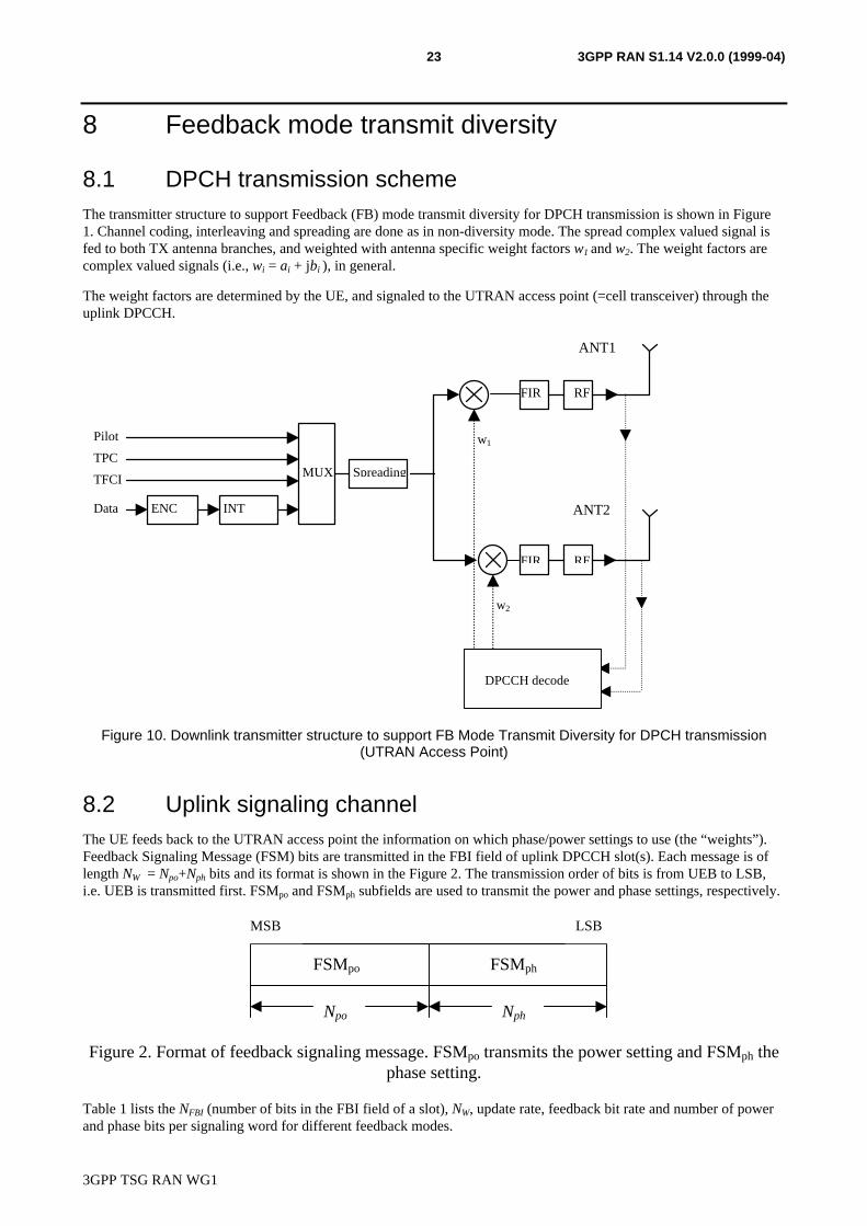
8.1 DPCH transmission schemeThe transmitter structure to support Feedback (FB) mode transmit diversity for DPCH transmission is shown in Figure1. Channel coding, interleaving and spreading are done as in non-diversity mode. The spread complex valued signal isfed to both TX antenna branches, and weighted with antenna specific weight factors w1 and w2. The weight factors arecomplex valued signals (i.e., wi = ai + jbi ), in general.
The weight factors are determined by the UE, and signaled to the UTRAN access point (=cell transceiver) through theuplink DPCCH.
MUX
INTENCData
TFCI
TPC
Pilot
Spreading
w1
w2
FIR RF
FIR RF
DPCCH decode
ANT1
ANT2
Figure 10. Downlink transmitter structure to support FB Mode Transmit Diversity for DPCH transmission(UTRAN Access Point)
8.2 Uplink signaling channelThe UE feeds back to the UTRAN access point the information on which phase/power settings to use (the “weights”).Feedback Signaling Message (FSM) bits are transmitted in the FBI field of uplink DPCCH slot(s). Each message is oflength NW = Npo+Nph bits and its format is shown in the Figure 2. The transmission order of bits is from UEB to LSB,i.e. UEB is transmitted first. FSMpo and FSMph subfields are used to transmit the power and phase settings, respectively.
FSMpo
MSB LSB
FSMph
Npo Nph
Figure 2. Format of feedback signaling message. FSMpo transmits the power setting and FSMph thephase setting.
Table 1 lists the NFBI (number of bits in the FBI field of a slot), NW, update rate, feedback bit rate and number of powerand phase bits per signaling word for different feedback modes.

3GPP TSG RAN WG1
3GPP RAN S1.14 V2.0.0 (1999-04)24
Table 1. NFBI, NW, update rate, feedback bit rate and number of power and phase bits persignalling word for different feedback modes
FB mode NFBI NW Update rate Feedback bit rate Npo Nph
1 1 1 1600 Hz 1600 bps 1 02 1 2 800 Hz 1600 bps 0 23 1 4 400 Hz 1600 bps 1 3
Tables 2 to 5 below give the binary signaling words, together with their interpretation at the transmit array (in terms ofrelative powers and phases to be applied between the antennas).
Table 2. Feedback mode 1 signalling message. No FSMph is transmitted.
FSMpo Power_ant1 Power_ant20 0 11 1 0
Table 3. Feedback mode 2 signalling message. No FSMpo is transmitted.
FSMph Phase_difference between antennas (degrees)00 18001 -9011 010 90
Table 4. FSMpo subfield of feedback mode 3 signalling message.
FSMpo Power_ant1 Power_ant20 0.2 0.81 0.8 0.2
Table 5. FSMph subfield of feedback mode 3 signalling message.
FSMph Phase difference between antennas (degrees)000 180001 -135011 -90010 -45110 0111 45101 90100 135
When Npo=0, equal power is applied to each antenna.
Antennas 1 and 2 are uniquely defined by their respective Primary CCPCH pilot codes.
The amplitude and phase applied per antenna is called a “weight”, and the set of weights is grouped into a “weightvector”. Specifically, the weight vector in the case of 2 antennas is given by
w =power _ ant1
power _ ant2.exp( jπ.phase _ diff / 180)
(1)
3GPP TSG RAN WG1
3GPP RAN S1.14 V2.0.0 (1999-04)25
8.3 Determination of feedback informationThe UE uses the pilots transmitted on the Primary CCPCH to separately estimate the channels seen from each antenna.
Once every NSlot=NW/NFBI slot times, the UE computes the phase and power adjustments that should be applied at theUTRAN access point to maximize the UE received power, from within the set of adjustments allowed by the chosenfeedback mode defined with Tables 1 to 5.
In a generic sense, this is the weight vector w that maximizes
P=wHHHHw (2)
where
H=[h1 h2 …]
and where the column vector hi represents the estimated channel impulse response for the i’th transmission antenna, oflength equal to the length of the channel impulse response.
8.4 Antenna verificationIn FB mode 1, if channel estimates are taken from the Primary CCPCH, the performance will also suffer if the UE cannot detect errors since the channel estimates will be taken for the incorrect antenna. To mitigate this problem, antennaverification can be done, which can make use of antenna specific pilot patterns of the dedicated physical channel. Theantenna verification can be implemented with several different algorithms. As an example if we have different pilotpatterns on the downlink DPCCH we can apply coherent antenna verification in which we select antenna with pilot
pattern 1s if the following relation holds,
2)(
)(lnˆ||||||||}Re{
1
2222
2121 s
swwywyw
P
PHH σ>+−− (2)
where )( 1sP and )(1)( 12 ss PP −= are the a priori probabilities for pilot patterns (=transmit antenna) 1s and 2s ,
respectively, 2σ̂ is an estimate of noise power, [ ] [ ][ ]TiLiiii Nsasa 1ˆ,,0ˆ ,1, −= Lw , [ ]y il is correlator output for
path l, and la ,1ˆ and $ ,a l2 denote the channel estimates for antennas. In normal operation the a priori probability for
selected pilot pattern is assumed to be 96% (assuming there are 4% of errors in the feedback channel for power controland antenna selection).
9 Reverse link synchronous transmission< Editor’s note: This clause is only to be found in ARIB Volume 3. Some more discussion on this technique is probablyneeded, and for now the original text is kept. The physical layer procedures of RSTS needs to be identified and furtherrefined and described in this clause. >
9.1 GeneralReverse Link Synchronous Transmission (RSTS) can reduce reverse link intra-cell interference by means of making anode B receive orthogonalized signals from UEs in the cell. To orthogonalize receiving signals from UEs,
- the same scrambling code is allocated to all dedicated physical channels in the cell,
- different orthogonal spreading codes are allocated to all dedicated physical channels across all UEs in the cell, and
- the signal arrival time of each UE is adjusted.
3GPP TSG RAN WG1
3GPP RAN S1.14 V2.0.0 (1999-04)26
The modulation scheme according to RSTS is described in <update 3.2.4.2.1.2.2>. The timing control procedures aredescribed later in this section. RSTS is an alternative technology applicable for low mobility terminals. A system mainlyaccommodating low mobility terminals may adopt the RSTS.
The transmission time control is carried out by two steps. The first step is initial synchronization and the second istracking.
1) Initial synchronization: Adjust transmission time through the initial timing control message over FACH
2) Tracking Process (Closed Loop Timing control): Adjust the transmission time through the Time Alignment Bit(TAB) over DTCH.
9.2 Initial synchronisation• When the node B received signal from UE over RACH, node B measures the difference in time between the
received timing and the reference time.
• The message for initial synchronization is delivered to UE via FACH.
• UE adjust its transmission time according to the message (the maximum amount of adjustments corresponds tothe round trip delay of a cell).
• When the difference in time of initial measurement in the first step is not big, it is possible to skip these initialsynchronization processes.
9.3 Tracking process• Node B periodically compares the difference between the reference time and received signal timing from UE.
• When the received timing is earlier than the reference time, Time Alignment Bit (TAB) = “0”. When this is laterthan the reference time, TAB = “1”.
• Since the timing control is carried out at much lower rate than TPC, TAB replaces the TPC bit every timingcontrol period 20 msec. (In the exemplary embodiment, the timing control period equals to the frame length ormultiples of it. In case of the example of timing control every frame, the first TPC bit of each frame is replacedby TAB )
• At the UE, soft decision on the TAB shall be performed, and when it is judged as “0”, the transmission time shallbe delayed by 1/4 (or 1/8) chip, whereas if it is judged as “1”, the transmission time shall be advanced by 1/4 (or1/8) chip.
9.4 Reference timeThe reference time is set up at the starting point of forward-link frame plus the median value between minimum andmaximum round trip delay within a cell. < Editor’s note: How can one take the median of two values? >
Annex A (informative):Other procedures
A.1 Paging procedure< Editor’s note: If it is decided to keep this clause, the network operation should be moved to S1.11, and the annexcould be renamed paging detection and possibly also moved to S1.11. >
3GPP TSG RAN WG1
3GPP RAN S1.14 V2.0.0 (1999-04)27
A.1.1 Network operation
Every UE belongs to one group. When there exists a paging message for the UE, the paging message is transmitted onthe PCH in the MUI-parts belonging to the UE’s group. The paging message includes the mobile station identificationnumber of the UE for which the paging message was intended. When a MUI is transmitted, the corresponding PI1 andPI2 fields are also transmitted.
The exact behaviour of the network is described as:
For the PCH of the group which does not have a paging message:
• The network shall transmit the two PI parts (PI1 and PI2) in the PCH as “all 0”.
• The MUI part shall not be transmitted.
For the PCH of the group which have a paging message:
• The network shall transmit the two PI parts (PI1 and PI2) in the PCH as “all 1”.
• The MUI part shall be transmitted within the same PCH.
A.1.2 UE operation
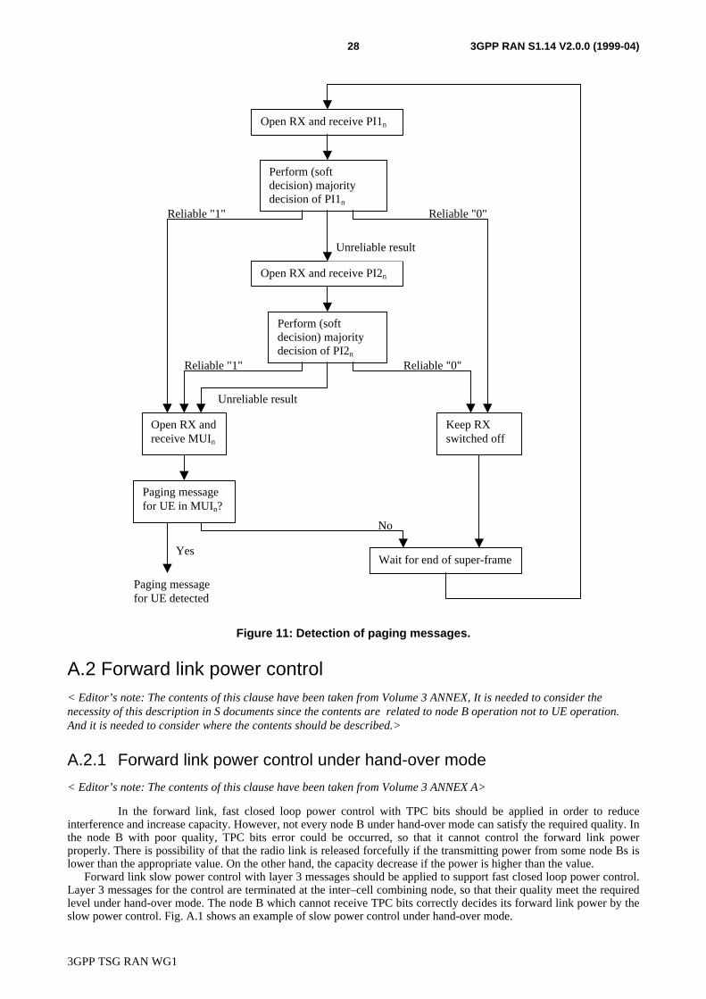
The idea behind the detection of paging messages is to open the receiver to detect one of or both the paging indicators(PI1 and PI2), and if they indicate a paging message for the group the UE belongs to, the actual paging information part(MUI) is received. When the MUI part is received, the existence of a paging message for the UE is determined from theinformation included in the MUI part.
The UE operation for detection of paging information in group n is shown in Figure 11. PI1n, PI2n, and MUIn are thePCH components belong to group n.
3GPP TSG RAN WG1
3GPP RAN S1.14 V2.0.0 (1999-04)28
No
Reliable "0"Reliable "1"
Unreliable result
Open RX and receive PI1n
Perform (softdecision) majoritydecision of PI1n
Open RX and receive PI2n
Perform (softdecision) majoritydecision of PI2n
Reliable "1" Reliable "0"
Unreliable result
Keep RXswitched off
Open RX andreceive MUIn
Wait for end of super-frame
Paging messagefor UE in MUIn?
Yes
Paging messagefor UE detected
Figure 11: Detection of paging messages.
A.2 Forward link power control< Editor’s note: The contents of this clause have been taken from Volume 3 ANNEX, It is needed to consider thenecessity of this description in S documents since the contents are related to node B operation not to UE operation.And it is needed to consider where the contents should be described.>
A.2.1 Forward link power control under hand-over mode
< Editor’s note: The contents of this clause have been taken from Volume 3 ANNEX A>
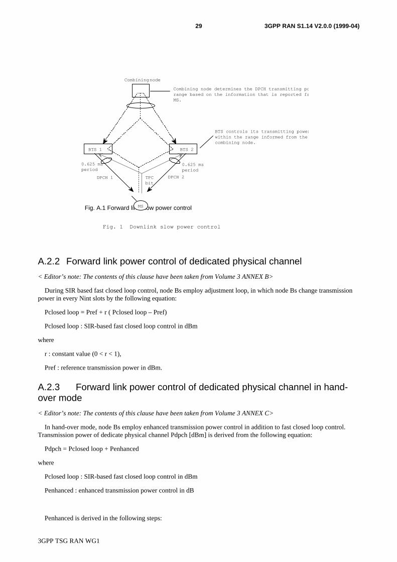
In the forward link, fast closed loop power control with TPC bits should be applied in order to reduceinterference and increase capacity. However, not every node B under hand-over mode can satisfy the required quality. Inthe node B with poor quality, TPC bits error could be occurred, so that it cannot control the forward link powerproperly. There is possibility of that the radio link is released forcefully if the transmitting power from some node Bs islower than the appropriate value. On the other hand, the capacity decrease if the power is higher than the value.
Forward link slow power control with layer 3 messages should be applied to support fast closed loop power control.Layer 3 messages for the control are terminated at the inter–cell combining node, so that their quality meet the requiredlevel under hand-over mode. The node B which cannot receive TPC bits correctly decides its forward link power by theslow power control. Fig. A.1 shows an example of slow power control under hand-over mode.
3GPP TSG RAN WG1
3GPP RAN S1.14 V2.0.0 (1999-04)29
A.2.2 Forward link power control of dedicated physical channel
< Editor’s note: The contents of this clause have been taken from Volume 3 ANNEX B>
During SIR based fast closed loop control, node Bs employ adjustment loop, in which node Bs change transmissionpower in every Nint slots by the following equation:
Pclosed loop = Pref + r ( Pclosed loop – Pref)
Pclosed loop : SIR-based fast closed loop control in dBm
where
r : constant value (0 < r < 1),
Pref : reference transmission power in dBm.
A.2.3 Forward link power control of dedicated physical channel in hand-over mode
< Editor’s note: The contents of this clause have been taken from Volume 3 ANNEX C>
In hand-over mode, node Bs employ enhanced transmission power control in addition to fast closed loop control.Transmission power of dedicate physical channel Pdpch [dBm] is derived from the following equation:
Pdpch = Pclosed loop + Penhanced
where
Pclosed loop : SIR-based fast closed loop control in dBm
Penhanced : enhanced transmission power control in dB
Penhanced is derived in the following steps:
Fig. A.1 Forward link slow power control
Fig. 1 Downlink slow power control
BTS 1
MS
BTS controls its transmitting power within the range informed from the combining node.
BTS 2
TPC bit
DPCH 2
Combining node
0.625 ms period
0.625 ms period
Combining node determines the DPCH transmitting power range based on the information that is reported from MS.
DPCH 1
3GPP TSG RAN WG1
3GPP RAN S1.14 V2.0.0 (1999-04)30
(a) node Bs set 0 [dB] to Penhanced.
(b) node Bs measure average SIR of Nave slots.
(c) If the average SIR is larger than Tsir + Texc (Tsir : target SIR in dB, Texc : allowable SIR range in dB),node Bs add Psup [dB] to Penhanced . If Penhanced is greater than Penhancedmax (Penhancedmax :maximum value of Penhanced in dB), node Bs set Penhancedmax to Penhanced.
(d) If the average SIR is equal to or small than Tsir + Texc, node Bs subtract Psdn [dB] from Penhanced. IfPenhanced is less than 0 [dB], node Bs set 0 [dB] to Penhanced.
Annex X:Description to be study in WG2
X.1 Outer loop power control< Editor’s note: The contents of this clause have been taken from Volume 3 section 3.2.6.7.1.2.2 and XX.07 subclause4.1.2. Details of outer loop should leave out, since it is a higher layer matter.>
In order to satisfy the required reception quality (average FER, or average BER), the UE should have an outer loopfunction that updates the reference SIR of fast closed loop transmitter power control depending on quality information.At the UE, outer loop control is performed based on the quality after maximum ratio combining upon DHO. In soft handover, the quality threshold for the cells in the active set should be adjusted by the outer loop power control (to beimplemented in the network nod ewhere soft handover combining is performed).
In outer loop, UE shall update the reference SIR when UE receives a frame that includes an error detection code (CRC).If CRC result is not OK, the reference SIR shall be raised by SIRINC dB. If CRC result is OK, the reference SIR shall bereduced by SIRDEC dB. SIRINC is 0.5 dB (tentative), and SIRDEC is derived from the following equation :
SIRDEC = SIRINC� FERTARGET /(1- FERTARGET ) ,
where FERTARGET is the target frame error rate. Initial reference SIR (SIRINIT) is dependent on services, and themaximum/minimum value of reference SIR is limited to SIRMAX/SIRMIN dB. SIRINIT ,SIRMAX, and SIRMIN are designatedvia Layer 3 message. The updates of the reference SIR may be conducted together for NILD frames when channelinterleaving depth is NILD frames.
X.2 Access Control for Multi-rate and/or Multi-code Packet DataTransmission
<Editor’s Note: The contents of this clause have been taken from section 3.2.6.10.3 in Volume 3.>
When communicating on RACH/FACH or DCH, the base station assigns more radio resources to lower-rate usersif the radio resources become free. The base station also controls the data rate according to the transmission powerand the channel conditions such as SIR of the forward-link. (SIR information is obtained by averaging TPCinformation from the mobile station. SIR information can be also used for adaptive control such as transmissiondiversity.)
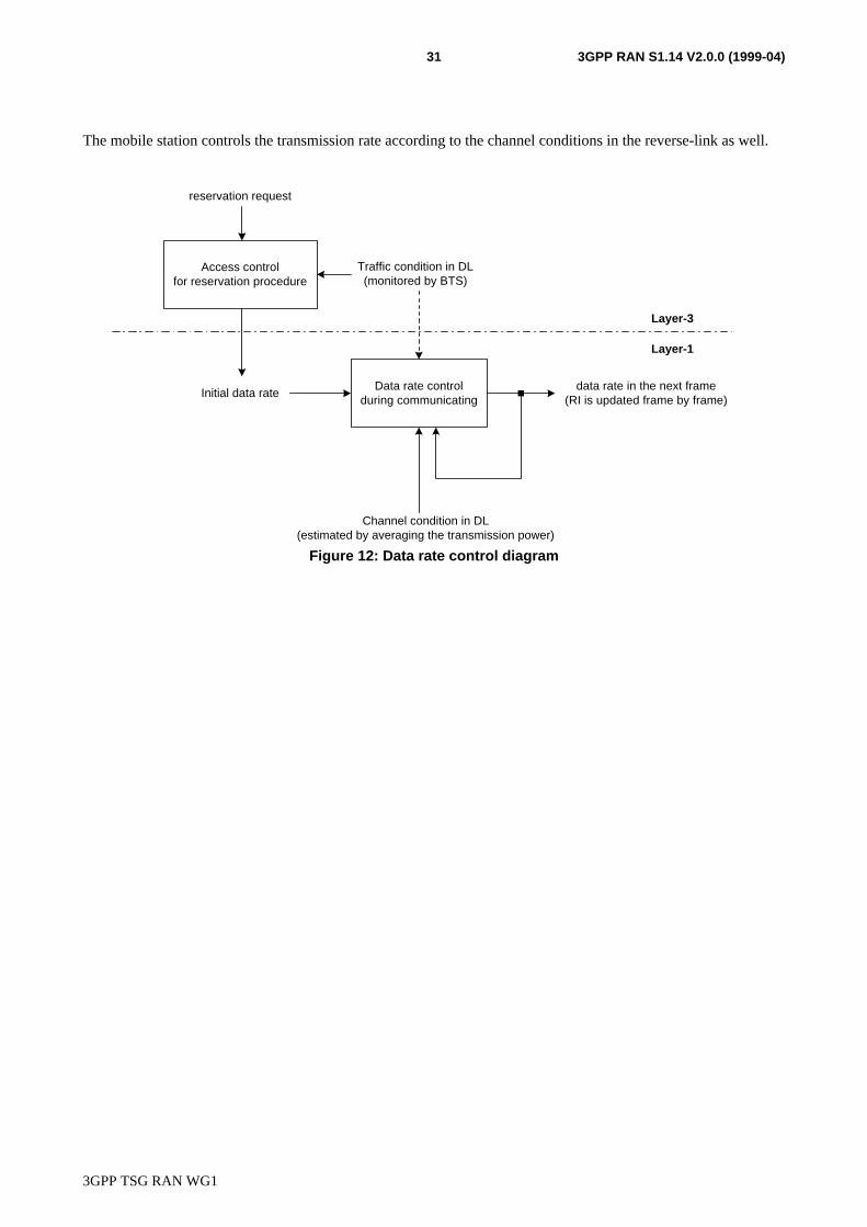
Figure 12 shows the data rate control diagram. The base station monitors the forward-link traffic condition, anddetermines the initial data rate for reservation requests by Layer-3 protocol. During communicating, the basestation estimates forward-link channel condition for each packet user by averaging the transmission power, andcontrols the data rate and transmission power in order to avoid excess interference in other mobile stations. If thetransmission power for target-SIR becomes higher than a threshold value, the base station lowers the transmissionrate and power in order to reduce the interference to other mobile stations. On the other hand, if the transmissionpower for higher rate becomes lower than a threshold value, the base station increases the transmission rate andpower in order to reduce channel occupancy. The threshold value is determined according to system environment,e.g., traffic condition. TFCI is updated frame by frame.
3GPP TSG RAN WG1
3GPP RAN S1.14 V2.0.0 (1999-04)31
The mobile station controls the transmission rate according to the channel conditions in the reverse-link as well.
Figure 12: Data rate control diagram
Data rate controlduring communicating
Channel condition in DL(estimated by averaging the transmission power)
data rate in the next frame(RI is updated frame by frame)
Traffic condition in DL(monitored by BTS)
Initial data rate
Access controlfor reservation procedure
reservation request
Layer-3
Layer-1

3GPP TSG RAN WG1
3GPP RAN S1.14 V2.0.0 (1999-04)32
History
Document history
V0.0.1 1999-02-12 Document created based on ETSI XX.07 V1.3.1 and ARIB Volume 3 ver. 1.0.
V0.1.0 1999-02-26 Version approved by WG1#2. The changes agreed at the meeting to incorporatee.g. ad hoc conclusions not yet included.
V1.0.0 1999-03-04 Version approved by TSG RAN. The changes agreed at the WG1#2 meeting toincorporate e.g. ad hoc conclusions not yet included.
V1.0.1 1999-03-17 Include adhoc conclusions in WG1#2
V1.0.2 1999-03-24 Include adhoc conclusions in WG1#3
V1.1.0 1999-03-25 Version approved by WG1#3.
V2.0.0 1999-04-20 Version approved by WG1#4
Editors for 3GPP TSG RAN S1.14 are:
Takehiro NakamuraNTT DoCoMo R&D HeadquartersTel: +81 468 40 31 90Mobile: +81 30 20 05 542Fax: +81 468 40 38 40E-mail: [email protected]
This document is written in Microsoft Word 97.