usrp-2900/2901 getting started guide - national · pdf filegetting started guide...
TRANSCRIPT
GETTING STARTED GUIDE
USRP-2900/2901Universal Software Radio Peripheral
This document explains how to install, configure, and test the following USRP devices:• USRP-2900 Software Defined Radio (USRP-2900)• USRP-2901 Software Defined Radio (USRP-2901)
ContentsElectromagnetic Compatibility Guidelines...............................................................................1Verifying the System Requirements..........................................................................................2Unpacking the Kit..................................................................................................................... 2
Verifying the Kit Contents................................................................................................ 3Preparing the Environment....................................................................................................... 4Installing the Software.............................................................................................................. 4Installing USRP-2900/2901 Devices........................................................................................ 5Configuring USRP-2900/2901 Devices....................................................................................5
Confirming USB Connection............................................................................................5Changing the Device ID....................................................................................................6
Programming the USRP-2900/2901......................................................................................... 8NI-USRP Instrument Driver............................................................................................. 8NI-USRP Examples.......................................................................................................... 8Verifying the Device Connection (Optional).................................................................... 8
Troubleshooting........................................................................................................................ 9Why Doesn't the USRP Device Appear in MAX?............................................................9Why Doesn't the USRP Device Appear in the NI-USRP Configuration Utility?.............9
Front Panels and Connectors.....................................................................................................9Direct Connections to the USRP-2900/2901.................................................................... 9USRP-2900 Connectors and LEDs................................................................................. 10USRP-2901 Connectors and LEDs................................................................................. 12
Worldwide Support and Services............................................................................................ 14
Electromagnetic Compatibility GuidelinesThis product was tested and complies with the regulatory requirements and limits forelectromagnetic compatibility (EMC) stated in the product specifications. These requirementsand limits provide reasonable protection against harmful interference when the product isoperated in the intended operational electromagnetic environment.
This product is intended for use in industrial locations. However, harmful interference mayoccur in some installations, when the product is connected to a peripheral device or test object,or if the product is used in residential or commercial areas. To minimize interference withradio and television reception and prevent unacceptable performance degradation, install anduse this product in strict accordance with the instructions in the product documentation.
Furthermore, any changes or modifications to the product not expressly approved by NationalInstruments could void your authority to operate it under your local regulatory rules.
Caution To ensure the specified EMC performance, operate this product only withshielded cables and accessories.
Caution To ensure the specified EMC performance, the length of all I/O cablesexcept those connected to the Ethernet and GPS antenna ports must be no longerthan 3 m (10 ft).
Caution This product is not approved or licensed for transmission over the airusing an antenna. As a result, operating this product with an antenna may violatelocal laws. Ensure that you are in compliance with all local laws before operatingthis product with an antenna.
Verifying the System RequirementsTo use the NI-USRP instrument driver, your system must meet certain requirements.
Refer to the product readme, which is available on the driver software media or online at ni.com/manuals, for more information about minimum system requirements, recommendedsystem, and supported application development environments (ADEs).
Unpacking the KitCaution To prevent electrostatic discharge (ESD) from damaging the device,ground yourself using a grounding strap or by holding a grounded object, such asyour computer chassis.
1. Touch the antistatic package to a metal part of the computer chassis.2. Remove the device from the package and inspect the device for loose components or any
other sign of damage.
Caution Never touch the exposed pins of connectors.
Note Do not install a device if it appears damaged in any way.
3. Unpack any other items and documentation from the kit.
Store the device in the antistatic package when the device is not in use.
2 | ni.com | USRP-2900/2901 Getting Started Guide
Verifying the Kit Contents
654
31 2
TX OUTPUT MAX +20 dBm, RX INPUT MAX -15 dBm, ALL RF PORTS 50 Ω
RF 0
TX1 RX1 RX2TX1 RX1
RX2
RF 1
NI USRP-290170 MHz–6 GHz
Designed by Ettus Research
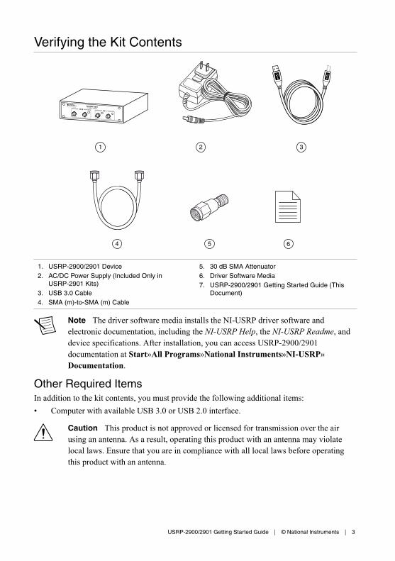
1. USRP-2900/2901 Device2. AC/DC Power Supply (Included Only in
USRP-2901 Kits)3. USB 3.0 Cable4. SMA (m)-to-SMA (m) Cable
5. 30 dB SMA Attenuator6. Driver Software Media7. USRP-2900/2901 Getting Started Guide (This
Document)
Note The driver software media installs the NI-USRP driver software andelectronic documentation, including the NI-USRP Help, the NI-USRP Readme, anddevice specifications. After installation, you can access USRP-2900/2901documentation at Start»All Programs»National Instruments»NI-USRP»Documentation.
Other Required ItemsIn addition to the kit contents, you must provide the following additional items:• Computer with available USB 3.0 or USB 2.0 interface.
Caution This product is not approved or licensed for transmission over the airusing an antenna. As a result, operating this product with an antenna may violatelocal laws. Ensure that you are in compliance with all local laws before operatingthis product with an antenna.
USRP-2900/2901 Getting Started Guide | © National Instruments | 3
Optional Items• Additional SMA (m)-to-SMA (m) cables to connect both channels with external devices
or to use the REF IN and PPS IN signals• 6 V, 3 A external DC power connector
Preparing the EnvironmentEnsure that the environment you are using the USRP-2900/2901 in meets the followingspecifications.
Ambient temperature range 0 °C to 55 °C
Operating temperature 23 °C ± 5 °C
Operating humidity 10% to 90% relative humidity, noncondensing
Pollution Degree 2
Maximum altitude 2,000 m
Indoor use only.
Caution Do not operate the USRP-2900/2901 in a manner not specified in thisdocument. Product misuse can result in a hazard. You can compromise the safetyprotection built into the product if the product is damaged in any way. If the productis damaged, return it to NI for repair.
Installing the SoftwareYou must be an Administrator to install NI software on your computer.1. Install an ADE, such as LabVIEW or LabVIEW Communications System Design
Software.2. Visit ni.com/info and enter the Info Code usrpdriver to access the driver download
page for the latest NI-USRP software.3. Download the NI-USRP driver software.4. Follow the instructions in the installation prompts.
Note Windows users may see access and security messages duringinstallation. Accept the prompts to complete the installation.
5. When the installer completes, select Restart in the dialog box that prompts you to restart,shut down, or restart later.
4 | ni.com | USRP-2900/2901 Getting Started Guide
Installing USRP-2900/2901 DevicesInstall LabVIEW Communications System Design Software and NI-USRP before you installthe hardware.
Note The USRP-2900/2901 device connects to a host computer using a standardUSB connector and USB cable.
1. Power on the computer.2. Attach the antenna or cable to the front panel terminals of the USRP-2900/2901 device as
needed for your application.3. Use the USB cable to connect the USRP device to the computer.
Note You can connect the USRP device to either a USB 3.0 or a USB 2.0port. If you use a USB 2.0 port, the maximum achievable sample rate may bereduced to 8 MS/s or less.
Note NI recommends that you connect the device to an external power supplywhen you use USB 2.0.
4. (Optional) Connect the AC/DC power supply to the PWR connector on the back panel ofthe USRP device, and plug the power supply into a wall outlet.
Note NI recommends that you connect the device to an external power supplyif you plan to use both channels of the USRP device. However, if you plan touse only one channel, bus power may be acceptable.
You can connect and synchronize multiple USRP-2900/2901 devices using an externalReference Clock distribution system such as the CDA-2990 Clock Distribution Device.However, USB performance varies when multiple devices stream through the same controller.Consider using a USRP RIO device if you need to build a high-channel count system.
Configuring USRP-2900/2901 Devices
Confirming USB Connection1. Select Start»All Programs»National Instruments»NI-USRP»NI-USRP
Configuration Utility to open the NI-USRP Configuration Utility.2. Select the Devices tab of the utility.
Your device should appear in the list on the left side of the tab, similar to the followingfigure.
USRP-2900/2901 Getting Started Guide | © National Instruments | 5
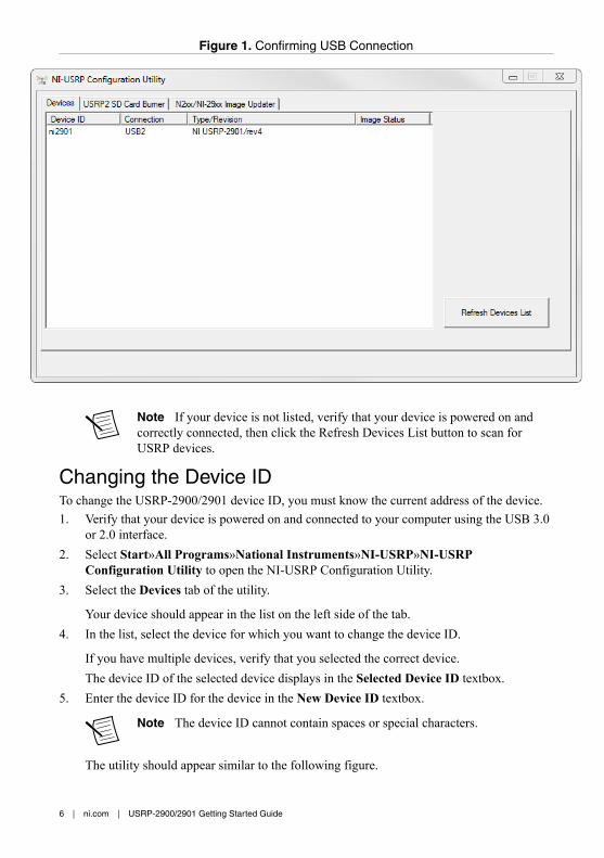
Figure 1. Confirming USB Connection
Note If your device is not listed, verify that your device is powered on andcorrectly connected, then click the Refresh Devices List button to scan forUSRP devices.
Changing the Device IDTo change the USRP-2900/2901 device ID, you must know the current address of the device.1. Verify that your device is powered on and connected to your computer using the USB 3.0
or 2.0 interface.2. Select Start»All Programs»National Instruments»NI-USRP»NI-USRP
Configuration Utility to open the NI-USRP Configuration Utility.3. Select the Devices tab of the utility.
Your device should appear in the list on the left side of the tab.4. In the list, select the device for which you want to change the device ID.
If you have multiple devices, verify that you selected the correct device.The device ID of the selected device displays in the Selected Device ID textbox.
5. Enter the device ID for the device in the New Device ID textbox.
Note The device ID cannot contain spaces or special characters.
The utility should appear similar to the following figure.
6 | ni.com | USRP-2900/2901 Getting Started Guide

Figure 2. Changing the Device ID
6. Click the Change Device ID button or press <Enter> to change the device ID.7. The utility prompts you to confirm your selection. Click OK if your selection is correct;
otherwise, click Cancel.8. The utility displays a confirmation to indicate the process is complete. Click OK.9. Power cycle the device to apply the changes.
Note After you change the device ID, you must power cycle the device andclick Find Devices in the utility to update the list of devices.
Configuring Multiple Devices with USBYou can connect multiple devices in the following ways:• Multiple USB 2.0 or 3.0 interfaces—One device for each interface• Single USB 2.0 or 3.0 interface—Multiple devices connected to a USB 2.0 or 3.0 hub
Tip Sharing a single USB 2.0 or 3.0 controller interface on your host computeramong multiple devices may reduce overall signal throughput. For maximum signalthroughput, NI recommends that you connect no more than one device per USBinterface.
To configure multiple devices connected to either separate USB 2.0 or 3.0 interfaces or to aUSB hub, assign a different device ID to each USRP device. Because each USRP-2900/2901device has the same default device ID, you must change the device ID for each USRP devicebefore you connect an additional device to the host computer.
USRP-2900/2901 Getting Started Guide | © National Instruments | 7
Programming the USRP-2900/2901
NI-USRP Instrument DriverNI-USRP features a set of VIs and properties that exercise the functionality of theUSRP-2900/2901, including configuration, control, and other device-specific functions. Referto the NI-USRP Help for information about using the instrument driver in your applications.
NI-USRP ExamplesThe instrument driver examples are instructional tools that demonstrate some of thefunctionality of the USRP-2900/2901. You can use these examples separately or integratethem into your systems. NI-USRP includes examples for getting started and other SDRfunctionality. You can access the NI-USRP examples from the following locations:• In LabVIEW Communications System Design Software at Learning»Examples»
Hardware Input and Output.• From the Start menu at Start»All Programs»National Instruments»NI-USRP»
Examples.• In LabVIEW from Functions»Instrument I/O»Instrument Drivers»NI‑USRP»
Examples palette.
You can access additional examples from the code sharing community at ni.com/usrp.
Note The NI Example Finder does not include NI-USRP examples.
Verifying the Device Connection (Optional)
Using LabVIEW Communications System Design SoftwareRun a VI to confirm that the device transmits and receives signals and is connected correctlyto the host computer.1. Navigate to Learning»Examples»Hardware Input and Output to create an example.2. Select the Single-Device Streaming project template for your device.3. Run Tx and Rx Streaming (Host).gvi.
If the device is transmitting and receiving signals, the front panel graphs displaywaveform data.
4. Click STOP to conclude the test.
Using LabVIEWPerform a loopback test to confirm that the device transmits and receives signals and isconnected correctly to the host computer.1. Attach the included 30 dB attenuator to one end of the SMA (m)-to-SMA (m) cable.2. Connect the 30 dB attenuator to the RX 2 TX 2 connector on the front panel of the USRP
device, and connect the other end of the SMA (m)-to-SMA (m) cable to the RX 1 TX 1port.
8 | ni.com | USRP-2900/2901 Getting Started Guide
3. On the host computer, open the niUSRP EX Tx Continuous Async example VI and run it.
If the device is transmitting signals, the IQ graph displays I and Q waveforms.4. Open the niUSRP EX Rx Continuous Async example VI and run it.
If the device is receiving signals, the IQ graph displays I and Q waveforms.
TroubleshootingIf an issue persists after you complete a troubleshooting procedure, contact NI technicalsupport or visit ni.com/support.
Why Doesn't the USRP Device Appear in MAX?MAX does not support USRP-2900/2901 devices. Use the NI-USRP Configuration Utilityinstead. Open the NI-USRP Configuration Utility from the Start menu at Start»AllPrograms»National Instruments»NI-USRP»NI-USRP Configuration Utility.
Why Doesn't the USRP Device Appear in the NI-USRPConfiguration Utility?1. Verify that the latest NI-USRP drivers are installed by running NI Update Service,
available from the Start menu at Start»All Programs»National Instruments»NIUpdate Service.
2. Check the LED status to ensure the device is powered correctly. If the LED is blue, thedevice is powered correctly using USB. If the LED is orange, the device is poweredcorrectly using external power.
3. Connect the device to a different USB port of the host computer, if one is available.4. Ensure that the latest drivers are installed for your USB controller.
Front Panels and Connectors
Direct Connections to the USRP-2900/2901The USRP-2900/2901 is an RF instrument that is sensitive to ESD and transients. Ensure youtake the following precautions when making direct connections to the USRP-2900/2901 toavoid damaging the device.
Caution Apply external signals only while the USRP-2900/2901 is powered on.Applying external signals while the device is powered off may cause damage.
• Ensure you are properly grounded when manipulating cables or antennas connected to theUSRP-2900/2901 TX1 RX 1 or RX2 connector.
• If you are using nonisolated devices, such as a nonisolated RF antenna, ensure the devicesare maintained in a static-free environment.
• If you are using an active device, such as a preamplifier or switch routed to theUSRP-2900/2901 TX1 RX 1 or RX2 connector, ensure that the device cannot generatesignal transients greater than the RF and DC specifications of the USRP-2900/2901 TX1RX 1 or RX2 connector.
USRP-2900/2901 Getting Started Guide | © National Instruments | 9
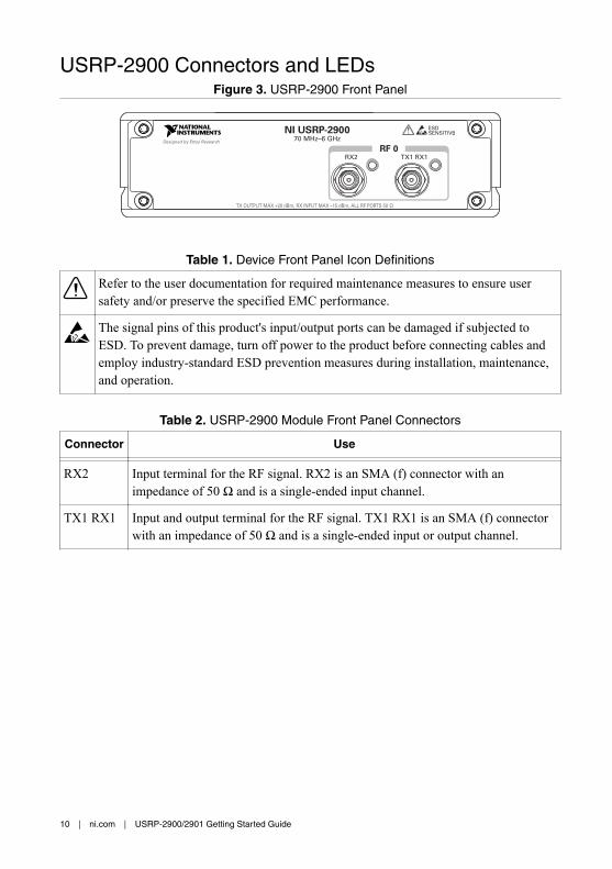
USRP-2900 Connectors and LEDsFigure 3. USRP-2900 Front Panel
NI USRP-290070 MHz–6 GHz
ESDSENSITIVE
TX OUTPUT MAX +20 dBm, RX INPUT MAX –15 dBm, ALL RF PORTS 50 Ω
RF 0TX1 RX1RX2
Designed by Ettus Research
Table 1. Device Front Panel Icon Definitions
Refer to the user documentation for required maintenance measures to ensure usersafety and/or preserve the specified EMC performance.
The signal pins of this product's input/output ports can be damaged if subjected toESD. To prevent damage, turn off power to the product before connecting cables andemploy industry-standard ESD prevention measures during installation, maintenance,and operation.
Table 2. USRP-2900 Module Front Panel Connectors
Connector Use
RX2 Input terminal for the RF signal. RX2 is an SMA (f) connector with animpedance of 50 Ω and is a single-ended input channel.
TX1 RX1 Input and output terminal for the RF signal. TX1 RX1 is an SMA (f) connectorwith an impedance of 50 Ω and is a single-ended input or output channel.
10 | ni.com | USRP-2900/2901 Getting Started Guide
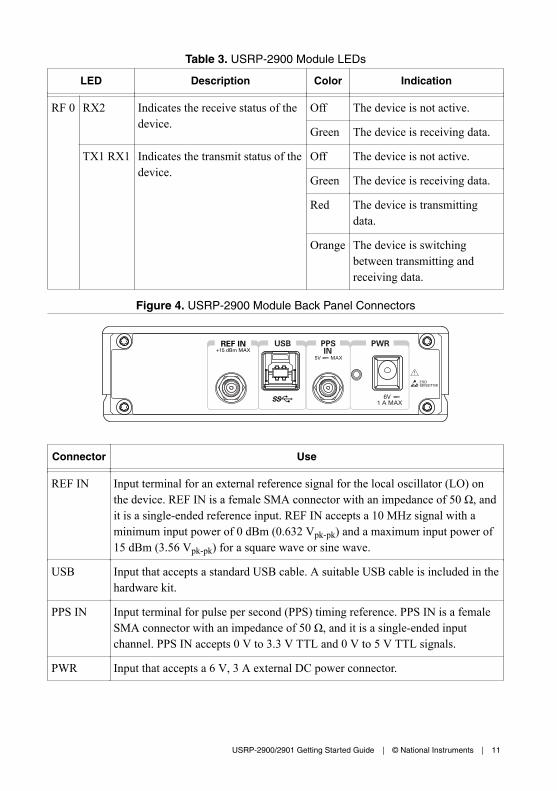
Table 3. USRP-2900 Module LEDs
LED Description Color Indication
RF 0 RX2 Indicates the receive status of thedevice.
Off The device is not active.
Green The device is receiving data.
TX1 RX1 Indicates the transmit status of thedevice.
Off The device is not active.
Green The device is receiving data.
Red The device is transmittingdata.
Orange The device is switchingbetween transmitting andreceiving data.
Figure 4. USRP-2900 Module Back Panel Connectors
+15 dBm MAXPPS
5V MAX
USB PWRIN
6V 1 A MAX
REF IN
Connector Use
REF IN Input terminal for an external reference signal for the local oscillator (LO) onthe device. REF IN is a female SMA connector with an impedance of 50 Ω, andit is a single-ended reference input. REF IN accepts a 10 MHz signal with aminimum input power of 0 dBm (0.632 Vpk-pk) and a maximum input power of15 dBm (3.56 Vpk-pk) for a square wave or sine wave.
USB Input that accepts a standard USB cable. A suitable USB cable is included in thehardware kit.
PPS IN Input terminal for pulse per second (PPS) timing reference. PPS IN is a femaleSMA connector with an impedance of 50 Ω, and it is a single-ended inputchannel. PPS IN accepts 0 V to 3.3 V TTL and 0 V to 5 V TTL signals.
PWR Input that accepts a 6 V, 3 A external DC power connector.
USRP-2900/2901 Getting Started Guide | © National Instruments | 11
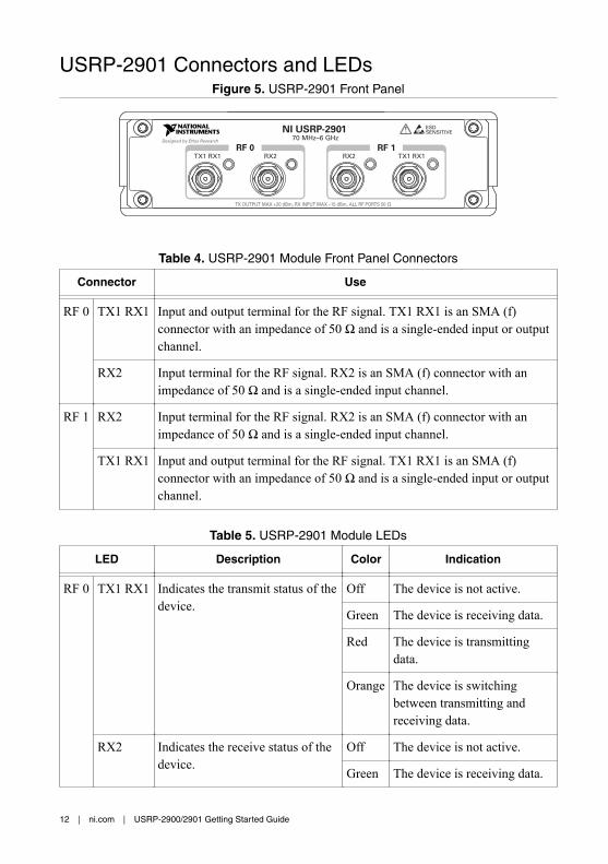
USRP-2901 Connectors and LEDsFigure 5. USRP-2901 Front Panel
NI USRP-290170 MHz–6 GHz
ESDSENSITIVE
RF 0TX1 RX1 RX2
RF 1TX1 RX1RX2
Designed by Ettus Research
TX OUTPUT MAX +20 dBm, RX INPUT MAX –15 dBm, ALL RF PORTS 50 Ω
Table 4. USRP-2901 Module Front Panel Connectors
Connector Use
RF 0 TX1 RX1 Input and output terminal for the RF signal. TX1 RX1 is an SMA (f)connector with an impedance of 50 Ω and is a single-ended input or outputchannel.
RX2 Input terminal for the RF signal. RX2 is an SMA (f) connector with animpedance of 50 Ω and is a single-ended input channel.
RF 1 RX2 Input terminal for the RF signal. RX2 is an SMA (f) connector with animpedance of 50 Ω and is a single-ended input channel.
TX1 RX1 Input and output terminal for the RF signal. TX1 RX1 is an SMA (f)connector with an impedance of 50 Ω and is a single-ended input or outputchannel.
Table 5. USRP-2901 Module LEDs
LED Description Color Indication
RF 0 TX1 RX1 Indicates the transmit status of thedevice.
Off The device is not active.
Green The device is receiving data.
Red The device is transmittingdata.
Orange The device is switchingbetween transmitting andreceiving data.
RX2 Indicates the receive status of thedevice.
Off The device is not active.
Green The device is receiving data.
12 | ni.com | USRP-2900/2901 Getting Started Guide
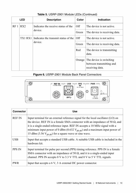
Table 5. USRP-2901 Module LEDs (Continued)
LED Description Color Indication
RF 1 RX2 Indicates the receive status of thedevice.
Off The device is not active.
Green The device is receiving data.
TX1 RX1 Indicates the transmit status of thedevice.
Off The device is not active.
Green The device is receiving data.
Red The device is transmittingdata.
Orange The device is switchingbetween transmitting andreceiving data.
Figure 6. USRP-2901 Module Back Panel Connectors
+15 dBm MAXPPS
5V MAX
USB PWRIN
6V 1 A MAX
REF IN
Connector Use
REF IN Input terminal for an external reference signal for the local oscillator (LO) onthe device. REF IN is a female SMA connector with an impedance of 50 Ω, andit is a single-ended reference input. REF IN accepts a 10 MHz signal with aminimum input power of 0 dBm (0.632 Vpk-pk) and a maximum input power of15 dBm (3.56 Vpk-pk) for a square wave or sine wave.
USB Input that accepts a standard USB cable. A suitable USB cable is included in thehardware kit.
PPS IN Input terminal for pulse per second (PPS) timing reference. PPS IN is a femaleSMA connector with an impedance of 50 Ω, and it is a single-ended inputchannel. PPS IN accepts 0 V to 3.3 V TTL and 0 V to 5 V TTL signals.
PWR Input that accepts a 6 V, 3 A external DC power connector.
USRP-2900/2901 Getting Started Guide | © National Instruments | 13
Worldwide Support and ServicesThe NI website is your complete resource for technical support. At ni.com/support, you haveaccess to everything from troubleshooting and application development self-help resources toemail and phone assistance from NI Application Engineers.
Visit ni.com/services for NI Factory Installation Services, repairs, extended warranty, andother services.
Visit ni.com/register to register your NI product. Product registration facilitates technicalsupport and ensures that you receive important information updates from NI.
A Declaration of Conformity (DoC) is our claim of compliance with the Council of theEuropean Communities using the manufacturer’s declaration of conformity. This systemaffords the user protection for electromagnetic compatibility (EMC) and product safety. Youcan obtain the DoC for your product by visiting ni.com/certification. If your product supportscalibration, you can obtain the calibration certificate for your product at ni.com/calibration.
NI corporate headquarters is located at 11500 North Mopac Expressway, Austin, Texas,78759-3504. NI also has offices located around the world. For telephone support in the UnitedStates, create your service request at ni.com/support or dial 1 866 ASK MYNI (275 6964). Fortelephone support outside the United States, visit the Worldwide Offices section of ni.com/niglobal to access the branch office websites, which provide up-to-date contact information,support phone numbers, email addresses, and current events.
Refer to the NI Trademarks and Logo Guidelines at ni.com/trademarks for information on NI trademarks. Other product andcompany names mentioned herein are trademarks or trade names of their respective companies. For patents covering NIproducts/technology, refer to the appropriate location: Help»Patents in your software, the patents.txt file on your media, or theNational Instruments Patent Notice at ni.com/patents. You can find information about end-user license agreements (EULAs)and third-party legal notices in the readme file for your NI product. Refer to the Export Compliance Information at ni.com/legal/export-compliance for the NI global trade compliance policy and how to obtain relevant HTS codes, ECCNs, and otherimport/export data. NI MAKES NO EXPRESS OR IMPLIED WARRANTIES AS TO THE ACCURACY OF THE INFORMATIONCONTAINED HEREIN AND SHALL NOT BE LIABLE FOR ANY ERRORS. U.S. Government Customers: The data contained inthis manual was developed at private expense and is subject to the applicable limited rights and restricted data rights as set forthin FAR 52.227-14, DFAR 252.227-7014, and DFAR 252.227-7015.
© 2015—2016 National Instruments. All rights reserved.
376357B-01 Dec16