using blender to create patterns - malanoski.com · using blender to create patterns by greg...
TRANSCRIPT

Using Blender To Create Patterns By Greg Malanoski
Introduction
Welcome to this short tutorial on using Blender to create height map patterns for your
CarveWright/CompuCarve system. If you know nothing about Blender it will be easy to dismiss it and feel that
it’s too difficult to use. However, if you take the time to learn some basics, you will find that it is fairly easy to
use and will increase your own personal capabilities. Blender was designed to create animated movies. It was
not designed to be a cad-type modeling program. Please keep that in mind as you are learning. Nevertheless, it
has been made available for FREE and requires no investment from you other than your time to learn it.
Recommended Prerequisites
Before we dig into the modeling aspect of this tutorial, you will need to download and install the latest version
of Blender (currently v2.45). It is also highly recommended that you review Neil Hirsig’s “Blender Learning
Units 1-5” (link below).
Let’s Get Started
Once you have Blender installed and have somewhat familiarized yourself with the user interface and basic
controls, it’s time to begin our new model. If you haven’t made any changes to your default scene, you should
have the default camera, light, and a mesh plane. Let’s delete these objects by selecting them with the right
mouse button (RMB), then press “x”. You will need to confirm your action by clicking “Erase selected
object(s)”. You should now have an empty scene (Note: My scene will probably differ from yours because I
have changed my default settings. Neal Hirsig’s tutorials cover this if you watch them.)

For the sake of simplicity, we are not going to create a complicated pattern. The intent of this tutorial is to teach
you how to get your models from Blender into a usable format for carving, not specifically pattern design. So,
we will use the “monkey” object supplied with Blender as our model. To add a new monkey object, press
“space” to get the menu, then maneuver to Add|Mesh|Monkey.

Once you add the monkey object, you should now be in “Edit Mode”. You can press “Tab” to return to “Object
Mode”. We can rotate our model, if desired. If we want to add a slight rotation, maybe to achieve an angled
profile, we can press the “r” key to enter rotation mode. To lock the rotation around the z-axis, press the “z”
key. Next, we type the degrees of rotation we want. I am going to chose 30 by typing “30”. I am then going to
commit that action by pressing “Enter”. You can certainly rotate any amount and along any axis you choose.
Please familiarize yourself by exploring! (Note: It is also possible to rotate in a freehand type mode)
If we were doing a complex model of our own, we would certainly spend a great deal of time manipulating the
object’s vertices to suit our needs. Fortunately, by using the supplied monkey, our model is now complete.
The next thing we want to do is to smooth our object. We can do this by pressing “F9” to display the “Editing”
panels. You will find the “Set Smooth” option on the “Link and Materials” sub panel. Click “Set Smooth” to
make the surfaces of our object smooth.

Next, we need to apply a material/texture to our object so that when we render we will have the depth info we
are looking for. So, we want to press “F5” to get the “Shading” panels. This is where we will define and apply
the material/texture to our object. Press the “Add New” button located on the “Links and Pipeline” sub panel.
On the “Material” tab, depress the “Shadeless” button. This will ensure that any lighting from the scene will
not affect our object during the render process.
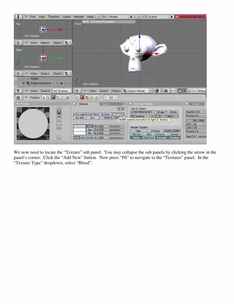
We now need to locate the “Texture” sub panel. You may collapse the sub panels by clicking the arrow in the
panel’s corner. Click the “Add New” button. Now press “F6” to navigate to the “Textures” panel. In the
“Texture Type” dropdown, select “Blend”.

We will be using a gradient blend to create the depth data for our object. We need to adjust the settings of our
gradient to black and white. Select the “Colors” tab. Increase the alpha channels value from .000 to 1.000 by
sliding the bar to the right (you can also click the text of this control and key it manually).
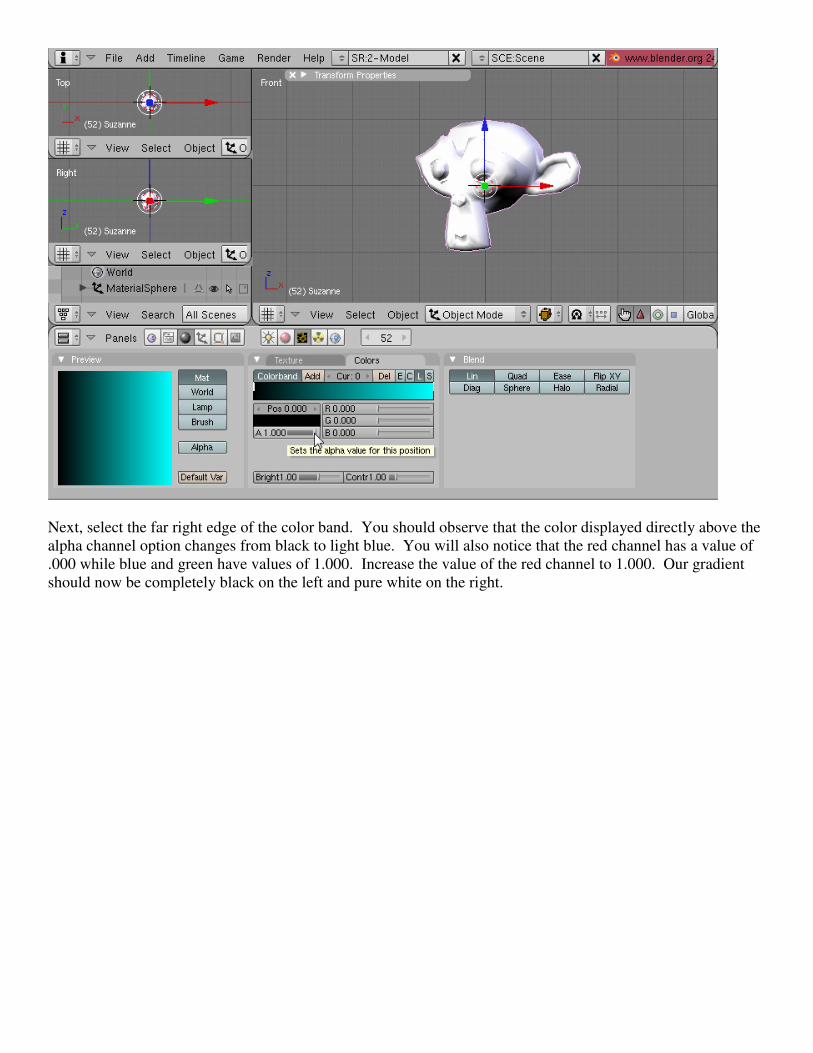
Next, select the far right edge of the color band. You should observe that the color displayed directly above the
alpha channel option changes from black to light blue. You will also notice that the red channel has a value of
.000 while blue and green have values of 1.000. Increase the value of the red channel to 1.000. Our gradient
should now be completely black on the left and pure white on the right.

Press “F5” to return to the materials panel and select the “Map Input” tab. If you look at the axis indicator
(lower left corner of the scene) and think about the perspective of our object, our depth here is along the y-axis.
Therefore, we need to map our texture to the z-axis because it is perpendicular to our depth axis. Select “z” in
the 3 axis options on the “Map Input” tab. (Note: I have not had consistent results with the axis settings nor
have I been able to find a definitive explanation as to how they are supposed to work)

We are nearly complete. All that remains is a camera and our output settings. Then we can render our model.
If you have followed all of my directions, your monkey will be outlined with a pinkish line (indicating it is
selected). Before we add our camera, we need to deselect this by pressing the “a” button. Once deselected,
press the space bar and select “Add|Camera”. You should see a new camera object in the center of your screen.
I have rotated to a side view to better display this.

Press the “n” key to display the “Transform Properties” window on your screen (I have had mine collapsed
throughout this tutorial). To move the camera back to a point where it can see our monkey object, change the
“LocY” coordinate value to something like “-5.000”. Hide the “Transform Properties” window by pressing the
“n” key again.
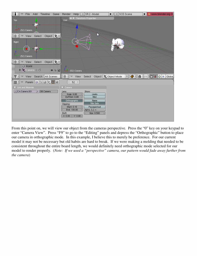
From this point on, we will view our object from the cameras perspective. Press the “0” key on your keypad to
enter “Camera View”. Press “F9” to go to the “Editing” panels and depress the “Orthographic” button to place
our camera in orthographic mode. In this example, I believe this to merely be preference. For our current
model it may not be necessary but old habits are hard to break. If we were making a molding that needed to be
consistent throughout the entire board length, we would definitely need orthographic mode selected for our
model to render properly. (Note: If we used a “perspective” camera, our pattern would fade away further from
the camera)

Before we adjust the “Scale” value, lets talk about the finished size of our pattern. If we wanted to make our
default pattern 6”x 6” at 128dpi (I believe 128dpi used to be the standard Designer dpi for importing patterns)
our final image would need to be 768 pixels wide by 768 pixels high.
Press the “F10” key to edit the “Scene” options. On the “Render” sub panel you can set the output size (25%,
50%, 75% or 100%). If your pc is slow, I would suggest a lower quality setting during design and full 100%
when you are ready to finalize. Let’s choose “100%” since our model is complete.
On the “Format” sub panel, change the X and Y values to 768 pixels (as calculated above). You will notice that
the camera view outline will change to show what will be captured. Next, select “PNG” from the file format
dropdown.

Now we can return to the “Editing” options by pressing “F9” and adjust the scale of our camera. A lower scale
setting will give a “zoom in” effect, and a “zoom out” effect will be achieved by increasing the scale value. A
value of “3.50” should suit our needs.

If we wanted to center our model, we could move either the camera, or the object. I’ll leave it as-is for now.
To render our work, we need to press “F12” and a new window will pop up with a preview of our image.

If we are satisfied, we then press “F3” to save and will be prompted for the filename in the file system browser.
Remember the location of your saved file so that we may import it into the Designer.
When we open the Designer, and open our new image, we will notice that the pattern must be inverted. Go
ahead and invert the pattern.

You can now perform and final manipulations and save to your pattern library.
You have now created a model, rendered an image, and imported a new pattern into your library!
Congratulations!
Realistically, the quality of this pattern leaves a lot to be desired and we would probably never use it. In this
example, the #1 contributor to the “blocky” feel is the lack of vertices. This could have been corrected by
subdividing the vertices in edit mode. You can also use subsurface modifiers
Conclusion
If you have made it this far you should now be able to recognize that Blender could potentially prove to be
invaluable for designing patterns for use on your CarveWright/CompuCarve system. I’m sure that this seemed
like a long and tedious process, but I assure you that once you are comfortable, this it will literally take you only
a couple of minutes from start to finish (excluding model design time, of course).
I hope that you will continue to research and learn Blender and use that knowledge to help others. The more
tools you have (and are fluent with) to design new patterns, the more you will benefit - not to mention all of the
free patterns you will be able supply everyone else (hint hint). ☺

Helpful Links
There is a wealth of information available on the internet for free. I encourage you to search the web. Below is
a very short list of what I have found and believe is helpful.
http://www.blender.org The Official Blender Homepage
http://www.gryllus.net/Blender/3D.html Neil Hirsig’s 3D Design Course (Tufts University) *** VERY
GOOD ***
http://www.blenderunderground.com Some good video tutorials
http://www.blendernation.com
Additional Observations
1. I have noticed that when you apply a material/texture to an object, the perspective of that
material/texture will move with the object. Therefore, it is recommended that you apply your
material/texture as a final step prior to rendering. If you do not, and you manipulate the object or
camera view, the rendering will not reflect your intended results.
2. All objects to be rendered for your pattern should be joined together as one mesh object. If they are not,
all objects will supply independent depth information and may not render as desired. To join multiple
objects, select each by holding the “shift” key and clicking with the RMB.
3. The default scene background (dark blue) will be displayed in the final rendering. It is impossible for
me to say what this value should be for your pattern. If you’d like to change it to better suit your
pattern, you may do so by changing the values in the “Shading” options for the “World” object.