acceleration of blender cycles path-tracing engine using
TRANSCRIPT

HAL Id: hal-01444507https://hal.inria.fr/hal-01444507
Submitted on 24 Jan 2017
HAL is a multi-disciplinary open accessarchive for the deposit and dissemination of sci-entific research documents, whether they are pub-lished or not. The documents may come fromteaching and research institutions in France orabroad, or from public or private research centers.
L’archive ouverte pluridisciplinaire HAL, estdestinée au dépôt et à la diffusion de documentsscientifiques de niveau recherche, publiés ou non,émanant des établissements d’enseignement et derecherche français ou étrangers, des laboratoirespublics ou privés.
Distributed under a Creative Commons Attribution| 4.0 International License
Acceleration of Blender Cycles Path-Tracing EngineUsing Intel Many Integrated Core Architecture
Milan Jaroš, Lubomír Říha, Petr Strakoš, Tomáš Karásek, Alena Vašatová,Marta Jarošová, Tomáš Kozubek
To cite this version:Milan Jaroš, Lubomír Říha, Petr Strakoš, Tomáš Karásek, Alena Vašatová, et al.. Acceleration ofBlender Cycles Path-Tracing Engine Using Intel Many Integrated Core Architecture. 14th ComputerInformation Systems and Industrial Management (CISIM), Sep 2015, Warsaw, Poland. pp.86-97,10.1007/978-3-319-24369-6_7. hal-01444507

Acceleration of Blender Cycles Path-TracingEngine using Intel Many Integrated Core
Architecture
Milan Jaros1,2, Lubomır Rıha1, Petr Strakos1, Tomas Karasek1,Alena Vasatova1,2, Marta Jarosova1,2, and Tomas Kozubek1,2
1IT4Innovations and 2Department of Applied Mathematics,VSB-Technical University of Ostrava, Czech Republic
email: [email protected]
Abstract. This paper describes the acceleration of the most computa-tionally intensive kernels of the Blender rendering engine, Blender Cy-cles, using Intel Many Integrated Core architecture (MIC). The pro-posed parallelization, which uses OpenMP technology, also improves theperformance of the rendering engine when running on multi-core CPUsand multi-socket servers. Although the GPU acceleration is already im-plemented in Cycles, its functionality is limited. Our proposed imple-mentation for MIC architecture contains all features of the engine withimproved performance. The paper presents performance evaluation forthree architectures: multi-socket server, server with MIC (Intel XeonPhi 5100p) accelerator and server with GPU accelerator (NVIDIA TeslaK20m).
Keywords: Intel Xeon Phi · Blender Cycles · Quasi-Monte Carlo · Path Tracing· Rendering
1 Introduction
The progress in the High-Performance Computing (HPC) plays an importantrole in the science and engineering. Computationally intensive simulations havebecome an essential part of research and development of new technologies. Manyresearch groups in the area of computer graphics deal with problems related toan extremely time-consuming process of image synthesis of virtual scenes, alsocalled rendering (Shrek Forever 3D – 50 mil. CPU rendering hours, [CGW]).
Beside the use of HPC clusters for speeding up the computationally intensivetasks hardware accelerators are being extensively used as well. They can furtherincrease computing power and efficiency of HPC clusters. In general, two typesof hardware accelerators could be used, GPU accelerators and MIC coprocessors.
The new Intel MIC coprocessor is composed of up to 61 low power cores interms of both energy and performance when compared to multi-core CPUs. Itcan be used as a standalone Linux box or as an accelerator to the main CPU.The peak performance of the top-of-the line Xeon Phi is over 1.1 TFLOP (1012
floating point operations per second) in double precision and over 2.2 TFLOPSin single precision. MIC architecture can be programmed using both sharedmemory models such as OpenMP or OpenCL (provides compatibility with codesdeveloped for GPU) and distributed memory models such as MPI.
The implementation presented in this paper has been developed and testedon Anselm Bullx cluster at the IT4Innovations National Supercomputing Centrein Ostrava, Czech Republic. Anselm cluster is equipped with both Intel XeonPhi 5110P and Tesla K20m accelerators [AHW]. For production runs, once thealgorithm is fully optimized, new IT4Innovations Salomon system will be used.Salomon will be equipped with 432 nodes, each with two coprocessors Intel XeonPhi 7120P [SHW].
1.1 Rendering Equation and Monte Carlo Path-Tracing method
In 1986 Kajiya first introduced the rendering equation in computer graphics[KAJ]. One of the last versions of this equation is represented as
Lo(x, ωo) = Le(x, ωo) +
∫Ω
Li(x, ωi)fr(x, ωi, ωo)(ωi · n)dωi, (1)
where ωo is direction of outgoing ray, ωi is direction of incoming ray, Lo
is spectral radiance emitted by the source from point x in direction ωo, Le isemitted spectral radiance from point x in direction ωo, Ω is the unit hemispherein direction of normal vector n with center in x, over which we integrate, Li isspectral radiance coming inside to x in direction ωi, fr(x, ωi, ωo) is distributionfunction of the image (BRDF) in point x from direction ωi to direction ωo, ωi ·nis angle between ωi and surface normal.
Rendering equation is fundamental algorithm for all algorithms of image syn-thesis based on ray tracing principle such as Path-Tracing. Solving the renderingequation is computationally extensive in general. The most common solutionmethods are based on numerical estimation of the integral (1). One of the mostcommonly used methods for numerical solution of equation (1) is Monte Carlo(MC) method. More information about this method can be found in the disser-tation thesis of Lafortune [LAF]. MC is also employed in different areas besidethe computer graphics, e.q. in statistics [GRE].
1.2 Quasi-Monte Carlo and Sobol’s sequence
One of the MC drawbacks is slow convergency, which is O(
1√N
), where N is
number of simulations. Due to this reason techniques that speed up the conver-gency and effectivity of the whole computation have been developed.
Deterministic form of Monte Carlo method is called quasi-Monte Carlo (QCM)
and its convergency speed is O(
(logN)s
N
), where s is dimension of the integral.
In order for O(
(logN)s
N
)to be smaller than O
(1√N
), s needs to be small and N
needs to be large [LEM]. In QMC method pseudo-random numbers are replaced
by quasi-random numbers that are generated by deterministic algorithms. Typ-ical property of such numbers is that they fill in the unit square more uniformly.This property is called low-discrepancy (LD). More details about it can be foundin [MOR], [NIE].
Let elements x1, . . . , xN are sequence of s-dimensional space [0, 1]s, then ap-proximation is expressed as∫
[0,1]sf(u) du ≈ 1
N
N∑i=1
f(xi). (2)
Well known types of LD sequences are Halton’s, Faure’s, Sobol’s, Wozniak’s,Hammersly’s or Niederreiter’s sequence. Blender uses Sobol’s sequences [JO3],[JO8], since they fit their needs - runs well on the CPU and accelerators, supportshigh path depth and can perform adaptive sampling.
Due to its property Sobol’s sequences can be used for progressive sampling.Unlike the Halton’s sequence which can be used for progressive sampling as well,Sobol’s sequences are not correlated in higher dimensions, and so do not needto be scrambled. The algorithm for generating Sobol’s sequences is explained in[BRA].
Any number from any dimension can be queried without per path pre-computation. Each dimension has its own sequence and when rendering thei-th pass, Blender gets element i from the sequence. A sequence is defined by a32× 32 binary matrix, and getting the i-th element in the sequence correspondsto multiplying the matrix by i. With binary operations this ends up being quitequick.
These matrices are not as simple to compute, but the data to generate themup to dimension 21201 is available online. Blender currently uses 4 dimensionsinitially to sample the subpixel location and lens and 8 numbers per bounce, sothat limits us to a maximum path depth of 2649 [BLS].
2 Implementation and Parallelization for MICAccelerator
The implementation presented in this paper is based on source code of theBlender version 2.73 that has been obtained from [BLE]. The code of Blenderis compiled using GNU compiler version gcc/4.9.0 and the library running onMIC coprocessor was compiled using intel/14.0.1 compiler. In order to enablenewly developed OpenMP and MIC accelerated rendering engines new OMPcomputing device has been added to GUI setting of Blender.
2.1 Parallelization for Multi-core CPU’s with Shared Memory
The core of the Cycles engine computation method implements quasi-MonteCarlo method with Sobol’s sequence. Rendered scene is represented as a C++global variable. If GPU or MIC acceleration is used this global variable has to be

transferred to the accelerator before rendering (solving the rendering equation(1)) is started. The synthesized image of size xr × yr is decomposed into tiles ofsize xt × yt (see Fig. 1). The way rendering algorithm itself is executed insidea tile differs for each computing device. We compare the performance of thefollowing computing devices: CPU (POSIX threads for CPU only, this is theoriginal computing device used by Blender Cycles), OpenMP (for CPU andMIC – newly developed computing device by our group), OpenCL (for CPU,MIC and GPU) and CUDA (for GPU only).
Original Implementation. The original computing device from BlenderCycles uses POSIX threads for parallelization. Parallelization is done in thefollowing way: the synthesized image of resolution xr × yr is decomposed intotiles of size xt × yt. Each tile is then computed by one POSIX thread/one CPUcore. The situation is shown in the Fig. 1.
Fig. 1. The decomposition of synthesized image with resolution xr × yr to tiles withsize xt×yt by original implementation. The one tile is computed by one POSIX threadon one CPU core for xt × yt pixels. This is an example of CPU16 - see Section 3.
2.2 OpenMP Parallelization of Intra Tile Rendering for CPU andMIC architecture
The newly proposed OpenMP parallelization is implemented in the OMP com-puting device. A hierarchical approach is used where each POSIX thread forkedby the Cycles renderer is further parallelized using OpenMP threads. In order toprovide enough work for each core of MIC coprocessor we need to decompose thelarger tile xt × yt to smaller sub-tile xo × yo to fully utilize the CPU hardware(this is an example of OMP15MIC or OMP8CPU2MIC - see Section 3). TheOpenMP parallelizes the loop of calculation across sub-tiles of the tile in a way
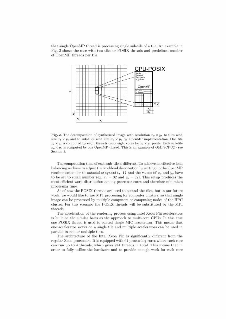
that single OpenMP thread is processing single sub-tile of a tile. An example inFig. 2 shows the case with two tiles or POSIX threads and predefined numberof OpenMP threads per tile.
xxt
r
yy t
r
1x tile8x cores8x threadsx*y pixelst t
OpenMP
CPU-POSIX
1x core1x thread
xo
y o
xc
y c
Fig. 2. The decomposition of synthesized image with resolution xr × yr to tiles withsize xt × yt and to sub-tiles with size xo × yo by OpenMP implementation. One tilext × yt is computed by eight threads using eight cores for xt × yt pixels. Each sub-tilexo × yo is computed by one OpenMP thread. This is an example of OMP8CPU2 - seeSection 3.
The computation time of each sub-tile is different. To achieve an effective loadbalancing we have to adjust the workload distribution by setting up the OpenMPruntime scheduler to schedule(dynamic, 1) and the values of xo and yo haveto be set to small number (ex. xo = 32 and yo = 32). This setup produces themost efficient work distribution among processor cores and therefore minimizesprocessing time.
As of now the POSIX threads are used to control the tiles, but in our futurework, we would like to use MPI processing for computer clusters, so that singleimage can be processed by multiple computers or computing nodes of the HPCcluster. For this scenario the POSIX threads will be substituted by the MPIthreads.
The acceleration of the rendering process using Intel Xeon Phi acceleratorsis built on the similar basis as the approach to multi-core CPUs. In this caseone POSIX thread is used to control single MIC accelerator. This means thatone accelerator works on a single tile and multiple accelerators can be used inparallel to render multiple tiles.
The architecture of the Intel Xeon Phi is significantly different from theregular Xeon processors. It is equipped with 61 processing cores where each corecan run up to 4 threads, which gives 244 threads in total. This means that inorder to fully utilize the hardware and to provide enough work for each core

to enable load balancing, each tile has to be significantly larger than in case ofCPU processing (see Fig. 3). In addition, the computation of each pixel takesdifferent time. To enable load balancing using OpenMP runtime engine we haveto set the scheduler to schedule(dynamic, 1).
xxt
r
yy t
r
MIC1x tile
1x thread1x pixel
1x core
x*y pixelst t
OpenMP
Fig. 3. The decomposition of synthesized image with resolution xr × yr to tiles withsize xt × yt by MIC implementation. The entire tile is computed by the coprocessor.Every pixel of the synthesized image is computed on one thread of the coprocessor.
Using the coprocessor with separate memory also requires the data transferbetween CPU memory and the memory of the coprocessor. Blender uses complexC++ structure that represents entire scene (KernelGlobals) and therefore in or-der to transfer data it has to be retyped to binary array (mic alloc kg()). Whencomputation ends, allocated memory of the coprocessor is cleaned (mic free kg()).
//Structure that represents entire scenestruct KernelGlobals
texture_image_uchar4 texture_byte_images[MAX_BYTE_IMAGES];texture_image_float4 texture_float_images[MAX_FLOAT_IMAGES];
#define KERNEL_TEX(type, ttype, name) ttype name;#define KERNEL_IMAGE_TEX(type, ttype, name)#include "kernel_textures.h"
KernelData __data;
//Declaration of variable for data transfer to MIC__declspec(target(mic : 0)) char *kg_bin = NULL;
//Transfer of data to MICvoid mic_alloc_kg(KernelGlobals *kgPtr, size_t kgSize)

kg_bin = (char *) kgPtr;
#pragma offload target(mic:0) \in(kg_bin:length(kgSize) alloc_if(1) free_if(0))
KernelGlobals* kg_mic = (KernelGlobals *)kg_bin;//...
//Main rendering processvoid mic_path_trace(int tile_h, int tile_w, int start_sample, int end_sample)
int size = tile_h*tile_w;
#pragma offload target(mic:0) \nocopy(kg_bin:length(0) alloc_if(0) free_if(0))for (int sample = start_sample; sample < end_sample; sample++)#pragma omp parallel for schedule(dynamic, 1)for (int i = 0; i < size; i++)int y = i / tile_w;int x = i - y * tile_w;kernel_path_trace(x,y);
//Allocated memory of the coprocessor is cleanedvoid mic_free_kg(...)
#pragma offload target(mic:0) \nocopy(kg_bin:length(0) alloc_if(0) free_if(1))
2.3 Parallelization by OpenCL and CUDA
The OpenCL computing device can be used for multi-core CPU’s as well as forMIC or GPU accelerators. Scene decomposition is similar to OpenMP processingfor MIC. Only one POSIX thread with a large tile for optimal performance isused due to previously discussed reasons. The parallelization is based on taskparallelism where for computing of one pixel a separate task is created (see Fig.4). The original code had to be modified in order to run on Intel Xeon Phi devices.Unfortunately rendering with textures did not work on MIC coprocessor. Dueto this shading and advance shading had to be disabled. There is no intentionto fix this malfunction, because the OpenCL is not a targeted platform for us(the OpenCL is limited like CUDA and it is hard to use for development andoptimization).

xxt
r
yy t
r
MIC, GPU, CPU1x tile
1x thread1x pixel
1x core
x*y pixelst t
OpenCL
. . .
...
Fig. 4. The decomposition of synthesized image with resolution xr × yr to tiles withsize xt×yt by OpenCL implementation. The entire tile is computed by the device. Forcomputing of one pixel is created one task.
As OpenCL and CUDA programing model are very similar, so is the decom-position. There is again one POSIX thread for main computation per accelerator.On GPU a rendering kernel uses single CUDA thread to render single pixel of atile. The GPU needs thousands threads for better performance. This is reason,why we need the large tile (see Section 3).
The GPU acceleration is a part of the original render engine. When com-pared to the our proposed approach it has limited functionality: the maximumamount of individual textures is limited, Open shading language (OSL) is notsupported, Smoke/Fire rendering is not supported, GPU has smaller memorythen MIC, GPU does not support cooperative rendering with CPU. We needthe all feature from CPU - that’s reason, why the combining of the CPU andGPU is useless for us.
3 Benchmark
In this paper two scenes are used for all benchmarks; one scene with and onewithout textures. The first scene with Tatra T87 has 1.2 millions triangles anduses HDRI lighting (see Fig. 5). The other scene with bones was generated fromCT images and has 7.7 millions triangles (see Fig. 5). It does not use textures.This scene is used to evaluate the performance of the OpenCL implementationfor Xeon Phi as it does not support textures.
The benchmark was run on single computing node of the Anselm supercom-puter equipped with two Intel Sandy Bridge E5-2470 CPU’s (used by CPUn,OMPn engines - n is number of cores used) and one Intel Xeon Phi 5110P(MIC) or one NVIDIA Tesla K20m coprocessor (GPU).

Fig. 5. (left) Benchmark 1: Model of Tatra T87. (right) Benchmark 2: Model of bonesgenerated from CT images.
In the next test we exploited the CPU-MIC hybrid system (OMP15MIC).The two tiles with large size are computed at the same time (2×POSIX threadswere created, one for CPU and one for MIC). First tile is computed by CPUusing 15× OpenMP threads and the other tile is computed by MIC coprocessor(1× core is used to manage MIC), see the results in the Table 1 and 4.
Another test we performed was a combination of OMP8 and CPU2. Thatmeans the computation of two tiles was parallelized (2×POSIX threads werecreated) and each tile was computed by 8×OpenMP threads, see the results inthe Table 1 and 4.
We also combined the CPU2 (2×tiles, each has one POSIX thread), OMP8(the each POSIX thread has 8×OpenMP threads) and MIC, see the results inthe Table 1 and 4. This combination is designed for the systems with multipleMIC accelerators (this will be the architecture of the Salomon – see Section 5).
For all tests, when OMP is used (OMP16, OMP8CPU2, OMP15MIC,OMP8CPU2MIC), the size of sub-tile 32×32px (see Section 2.2).
The division of the image into tiles has to be made carefully. You can see thebig time when CPU16 is used and the size of tile is 1024×1024. In this examplethe 12×cores are idle (see the Table 1 and 4).
3.1 Benchmark 1: Tatra T87
For this scene resolution 2048× 2048px was used. First we compared the calcu-lation for different size of tiles for the same resolution (see Table 1). In next twotests the resolution and count of samples were changed (see Table 2 and 3).
3.2 Benchmark 2: Bones
The original implementation of OpenCL does not work on Intel Xeon Phi. Theproblem is with shading and advance shading which has to be disabled. For thisreason, we created a new scene, just for OpenCL testing. The Table 4 comparesruntimes (in minutes) for different numbers of tiles. The Table 5 shows the resultusing OpenCL.

32×32 64×64 128×128 256×256 512×512 1024×1024
CPU16 03:08 03:10 03:12 03:19 06:54 (8cores) 13:10 (4cores)OMP16 44:42 12:41 04:08 03:31 03:12 03:09OMP8CPU2 22:01 06:39 03:34 03:17 03:12 03:25GPU 34:58 12:11 05:42 03:43 03:09 03:06MIC 25:40 11:30 07:38 06:38 06:22 06:17OMP15MIC 14:08 05:52 03:21 02:30 02:18 02:30OMP8CPU2MIC 10:41 04:07 02:40 02:22 02:21 03:01
Table 1. Benchmark 1: In the table we can see the time in minutes for different sizeof tiles. The test was executed for: Samples: 256, and Resolution: 2048× 2048px.
256 512 1024 2048
CPU16 00:47 03:03 03:16 06:48 (8cores)OMP16 00:05 00:14 00:50 03:11GPU 00:07 00:15 00:53 03:09MIC 00:09 00:27 01:39 06:23OMP15MIC 00:09 00:27 00:40 02:20
Table 2. Benchmark 1: In the table we can see the time in minutes for differentresolutions. The test was executed for: Samples: 256, Tiles:512× 512px.
32 64 128 256 512 1024
CPU16 00:55 01:46 03:30 06:50 13:35 (8cores) 27:18 (4cores)OMP16 00:28 00:51 01:38 03:12 06:19 12:40GPU 00:39 01:14 02:22 04:40 09:16 18:31MIC 00:59 01:44 03:17 06:22 12:34 24:59OMP15MIC 00:23 00:40 01:12 02:18 04:31 09:05
Table 3. Benchmark 1: In the table we can see the time in minutes for count of samples.The test was executed for: Tiles: 512× 512px, Resolution: 2048× 2048px.
32×32 64×64 128×128 256×256 512×512 1024×1024
CPU16 03:28 03:30 03:36 03:53 05:50 (8cores) 17:20 (4cores)OMP16 49:08 13:37 04:20 03:49 03:39 03:36OMP8CPU2 24:35 07:07 03:52 03:42 03:37 03:36GPU 30:42 09:17 04:45 03:28 03:15 03:17MIC 57:56 20:43 10:37 07:50 07:06 06:54OMP15MIC 25:54 08:17 04:02 02:54 02:39 02:32OMP8CPU2MIC 17:10 05:27 03:12 02:43 02:39 02:36
Table 4. Benchmark 2: In the table we can see the time in minutes for differentnumbers of tiles. The test was executed for: Samples: 256, Resolution: 2048× 2048px.

32×32 64×64 128×128 256×256 512×512 1024×1024 2048×2048
CPUCL 06:44 05:46 05:18 05:06 05:01 05:02 05:07GPUCL 35:58 11:08 04:46 04:03 03:47 03:49 03:50MICCL 01:04:34 21:23 14:37 10:34 09:41 09:10 08:47
Table 5. Benchmark 2: In the table we can see the time in minutes for differentnumbers of tiles using OpenCL. The test was executed for: Samples: 256, Resolution:2048× 2048px.
4 Conclusion
Both benchmarks show that the best performance could be obtained in casewhen combination of CPU and MIC coprocessor (OMP15MIC) is used. We cansee from the results that the MIC coprocessor behaves like a 6-cores CPU unit.On the other hand, the MIC accelerator adds only 1.37 speedup over CPU im-plementation, which is less than expected. We would expect at least the sameperformance boost as in case of GPU accelerators. The reason why Intel MICdoes not provide the expected performance boost is due to insufficient vector-ization in the code for calculation the rendering equation (512 bit registers (ableto hold 16 floats) are wasted now).
We also show that the combination of full CPU utilization and MIC (OMP15MIC)has the advantage over GPU parallelization. Advantages are as follows:
– GPU parallelization does not use all CPU cores– GPU does not offer all features of our MIC implementation, which has iden-
tical feature set as the original CPU implementation– The combination of 2 POSIX threads, each thread running on one socket,
and 2× MIC is designed for the systems with multiple MIC accelerators (thiswill be the architecture of the Salomon – see Section 5)
5 Future Work
In the future work we will focus on vectorization of the code to improve its per-formance on Intel Xeon Phi devices. We will also modify the existing implemen-tation of the Path-Tracing method using MPI technology. Our new benchmarkswill target the new supercomputer Salomon which will be equipped with twoIntel Xeon Phi for better performance.
Acknowledgment
This paper has been elaborated in the framework of the project New creativeteams in priorities of scientific research, reg. no. CZ.1.07/2.3.00/30.0055, sup-ported by Operational Programme Education for Competitiveness and cofi-nanced by the European Social Fund and the state budget of the Czech Republic.The work was also supported by the European Regional Development Fund in
the IT4Innovations Centre of Excellence project (CZ.1.05/1.1.00/02.0070), theProject of major infrastructures for research, development and innovation ofMinistry of Education, Youth and Sports with reg. num. LM2011033 and by theVSB-TU Ostrava under the grant SGS SP2015/189.
References
[CGW] Intel: Animation Evolution: A Biopic Through the Eyes of Shrek, ComputerGraphic World, December 2010
[KAJ] Kajiya, J.: The rendering equation, Computer Graphics, vol. 20, pp. 143–150,August 1986
[LAF] Lafortune, E.: MathematicalModels and Monte Carlo Algorithms for PhysicallyBased Rendering, Cornell University, PhD. Dissertation, February 1996
[GRE] Gregor, L.: Overenı ocenenı opcı metodou quasi-Monte-Carlo, 5. mezinarodnıkonference Financnı rızenı podniku a financnıch institucı, VSB-TU Ostrava,2005
[NIE] Niederreiter, H.: Random number Generation and quasi-Monte Carlo Methods.SIAM, Philadelphia, ISBN 0-89871-295-5, 1992
[MOR] Morokoff, W.J.: Generating quasi-Random Paths for Stochastic Processes,Working Paper, Mathematics Dept. of UCLA, 1997
[JO3] Joe, S. and Kuo, F. Y.: Remark on Algorithm 659: Implementing Sobol’s quasi-random sequence generator, ACM Trans. Math. Softw. 29, 49-57, 2003
[JO8] Joe, S. and Kuo, F. Y.: Constructing Sobol sequences with better two-dimensional projections, SIAM J. Sci. Comput. 30, 2635-2654, 2008
[BRA] Bratley, P. and Fox, B. L.: Algorithm 659: Implementing Sobol’s quasi-randomsequence generator, ACM Trans. Math. Software, 14, pp. 88–100, 1988
[LEM] Lemieux, Ch.: Monte Carlo and Quasi-Monte Carlo Sampling, Springer, ISBN978-1441926760, 2009
[AHW] https://docs.it4i.cz/anselm-cluster-documentation/hardware-overview[SHW] https://docs.it4i.cz/salomon/hardware-overview[BLE] http://www.blender.org/[BLS] http://wiki.blender.org/index.php/Dev:2.6/Source/Render/Cycles/Sobol