users reference manual - textfiles.com · adm-42 data display terminal lear siegler,inc. users...
TRANSCRIPT

ADM-42 data
display terminal
LEAR SIEGLER,INC.
USERS REFERENCE MANUAL
DP-110 ©1979 lEAR SiEGLER, iNC. FEBRUARY 1980
LEAR SIEGLER, INC. DATA PRODUCTS DIVISION
TABLE OF CONTENTS
SECTION
1 GENERAL DESCRIPTION •••••••••••••••••••••••••
1.1 INTRODUCT ION •••••••••••••••••••••••••••
1.2 PURPOSE AND USE ••••••••••••••••••••••••
1.3 OPERATIONAL DESCRIPTION •••••••••••••••• 1.3. 1 Regulated Power Supply .. ' ..... . 1.3.2 Keyboard ..................... . 1.3.3 Control Section (CPU) ••••••••• 1.3.4 Video Logic and Control ...... . 1.3.5 External Interfacee ••......•.. 1.3.6 System Configuration Switches.
1.4 PHYSICAL DESCRIPTION •••••••••••••••••••
1.5 SPECIFICATIONS ••••••••••••••••••••••••• 1.5.1 Transmission Modes ........... . 1. 5 . 2 Character Format ............. . 1.5.3 Word Structure ............... . 1.5.4 Configuration Control ........ .
1.6 ADM- 4 2 OPTIONS •••••••••••••••••••••••••
1.7 RELATED DOCUMENT •••••••••••••••••••••••
2 IN S T A LLA T ION • • • • • • • • • • • • • • • • • • • • • • • • • • • • • • • •
2.1 INTRODUCTION •••.•••••••••.•••••••••••••
2.2 SAFETY REQUIREMENTS ••••••••••••••••••••
2.3 SITE REQUIREMENTS ••••••••••••••••••••••
2.4 UNPACKING AND INITIAL INSPECTION •••••••
2.5 INITIAL PREPARATION •••••••••••••••••••• 2.5.1 Line Voltage Selection ....... . 2.5.2 Configuration Control Switch
PAGE
1-1
1-1
1-1
1-2 1-2 1-4 1-4 1-4 1-4 1-5
1-5
1-6 1-6
1-10 1-10 1-10
1-14
1-17
2-1
2-1
2-1
2-1
2-2
2-2 2-2
Settings...................... 2-2
i
LEAR SIEGLER, INC. DATA PRODUCTS DIVISION
TABLE OF CONTENTS (continued)
SECTION PAGE
3
2.6
2.7
INTERFACE INFORMATION STANDARD PCBA ..... 2.6.1 MODEM Port Interface .... e ••••••
2.6.2 EXTENSION Port Interface ...... .
INTERFACE INFORMATION, OPTION PCBA ..... . 2.7.1 PARALLEL PRINTER Port Inter-
2-3 2-3 2-3
2-3
face. . . . . . . . . . . . . . . . . . . . . . . . . . . 2-3 2.7.2
2.7.3
ASYNCHRONOUS PRINTER Port Interf ace .•............ c ...... . SYNCHRONOUS Port Interface ..•..
2-3 2-3
2.8 INSTALLING THE ADM-42 ................... 2-10
2.9 TURN-ON AND TURN-OFF PROCEDURES ......... 2-10
OPERATING INSTRUCTIONS •••••••••••••••••••••••
3.1
3.2
3.3
3.4
3.5
INTRODUCTION ........................... .
KEYBOARD 3.2.1 3.2.2 3.2.3 3.2.4
FUNCTIONS ..................... . Terminal Control Keys •......... Alphanumeric Keys .......•...... Special Character Keys ........ . Operational Control Keys ...... .
CURSOR CONTROL OPERATIONS .............. .
DATA EDITING CONTROL OPERATIONS ........ . 3.4. 1 Editing Examples .............. .
DATA TRANSMISSION CONTROL OPERATIONS .... 3.5.1 3.5.2 3.5.3
3.5.4 3.5.5
3.5.6 3.5.7
Transmission (Baud) Rates ..... . Block Mode Transmission ..•..... Example of Block Mode Trans-mission ....................... . Conversation Mode Transmission. Example of Conversation Mode Transmission .................. . Serial Print Mode Transmission. Parallel Print Mode Trans-
3-1
3-1
3-1 3-3 3-8 3-8 3-8
3-9
3-10 3-13
3-16 3-16 3-16
3-17 3-18
3-19 3-20
m~ss~on. . . . .. . . . . . . . . . . . . . . . . . . 3-22 3.5.8
3.5.9 3.5.10
Buffered Print Mode Trans-missionc ...................... . ADM-l Mode Transmission ....... . Polling Mode Transmission ..... .
ii
3-22 3-22 3-22
LEAR SIEGLER, INC. DATA PRODUCTS DIVISION
SECTION
3.6
3.7
3.8
3.9
3.10
TABLE OF CONTENTS (continued)
PROGR,AM MODE ....•.•••........•. 0 ......... .
PAGE
3-22
3-23 3-23 3-24
SPECIAL ADM-42 CHARACTERISTICS •..••••.•. 3.7.1 Protected Fields/Characters ..•• 3.7.2 Status Line Characteristics ••..
PROGRAMMING CONSIDERATIONS ...•........•. 3-25 3-25 3-38
3.8.1 CTRL Key Operations ........... . 3.8.2 ESC Key Operations .....•.•..... 3.8.3 Function Key (FUNKEY) Opera-
3.8.4 3.8.5
3.8.6 3"SQ7 3.8.8
3.8.9
3.8.10
STANDARD 3.9.1 3.9.2
3.9.3
3.9.4
3.9.5
SPECIAL 3.10.1 3.10.2 3.10.3
3.10.4
tions .............................. 3-38 Personality Control Operations. 3-42 Terminal/Mode Control Operations ..................... 3-46 Cursor Control Operations ....•. 3-47 Format Control Operations •.•..• 3-48 Data Editing Control Operations ....................• 3-49 Data .Transmission Control Operations ..................... 3-51 Video Attribute Control ........ 3-53
(ADM-2) POLLING ..............•. 3-55 Setting ADM-42 Address ......... 3-55 Standard (ADM-2) Polling Operations ..................... 3-55 Removing Terminal from Standard Polling Status................. 3-57 Initiating Standard Polling Sequence. . . . . . . . . . . . . . • . . . . . . .. 3- 58 Standard (ADM-2 Compatible) Res po n s e s . . . . . . . . . . . . . . . . . . . . . . 3 - 5 8
POLLING OPERATIONS .............. 3-70 GROUP POLL Operations .......... 3-70 GROUP SELECT Operations ........ 3-71 MULTI-POINT CONTENTION Operations ..................... 3-71 Addressable Printer Port Operations ..................... 3-71
iii
LEAR SIEGLER, INC. DATA PRODUCTS DIVISION
TABLE OF CONTENTS (continued)
APPENDIX A
Operator's Quick Reference Guide TO Baud Rate Change ... Operator's Quick Reference Guide To Personality Change. Operator's Quick Reference Guide To Video Attribute Con tro 1 Sequence. e •••••••••••••••••••••••••••••••••••••
Operator's Quick Reference Guide TO CTRL Key Sequence .. Operator's Quick Reference Guide To Graphic Character Set Code s ..... e _ ••••• II •••••• " ••••••••• " • III •••••••••••• til •
Operator's Quick Reference Guide To Escape Sequence .... Operator's Quick Reference Guide To Absolute Cursor Positioning Sequence .................................. . Operator's Quick Reference Guide To FUNKEY Programming. Operator's Quick Reference Guide To Buffered Print Mode .......••...•......................................
FIGURE
1-1 1-2 1-3
1-4 1-5
1-6
2-1 2-2 2-3
2-4
2-5
2-6 2-7
LIST OF FIGURES
ADM-42 Data Display Terminal ...................• ADM-42 Data Flow Block Diagram ...............••. ADM-42 Character Format (By Ascending ASCII Codes) With HEX Code ..............•............. Word Format Codes With DIP Switch Configuration. Standard PCBA Component and Interface Connector Locations .......•...........•......... Option PCBA Component and Interface Connector Locations ............................ .
Typical ADM- 42 Interfaces ...................... . ADM-42 Standard PCBA Interface Logic ........... . Option PCBA CPU Bus Extension Interface Connector/Pin List ..............•....•.......... Option PCBA Parallel Printer Port Interface Log i c ..•....•........................•.......•.. Option PCBA Asynchronous Serial Printer Port Interface Logic ................................ . Option PCBA Synchronous Port Interface Logic ... . Location of ADM-42 Controls and Interface
PAGE
A-I A-2
A-4 A-5
A-6 A-7
A-8 A-9
A-lO
PAGE
viii 1-3
1-11 1-12
1-15
1-17
2-4 2-5
2-6
2-7
2-8 2-9
Connectors. . . . . . . . . . . . . . . . . . . . . . . . . . . . . . . . . . . . . . 2 -12
3-1 ADM-42 Data Display Terminal Standard Keyboard.. 3-2 3-2 ADM-42 Standard Graphic Character Set, Showing
Comparable CTRL Codes ........................... 3-26 3-3 ADM-42 Escape Sequence Characters, With HEX
Coding.......................................... 3-40
iv

LEAR SIEGLER, INC. DATA PRODUCTS DIVISION
LIST OF FIGURES (continued)
FIGURE PAGE
3-4 Chart of Absolute Cursor Positioning Codes..... 3-50 3-5 POLL Function Dialogue, Flow Diagram........... 3-59 3-6 SELECT Function Dialogue, Flow Diagram......... 3-62 3-7 SEQUENTIAL SELECT Function Dialogue, Flow
Diagram. !! • e e e e .. G 0 C a ... a _ • • • • • • • • • • • • • • • • • • • • • • • • 3-64 3-8 FAST SELECT Function Dialogue, Flow Diagram.... 3-66 3-9 B~OADCAST SELECT Function Dialogue, Flow
D~agram. • . •• • •• • •• . • • •. • • • . • ••• • • • • •• • • • .• • • • •• 3-67 3-10 SEND Function Dialogue, Flow Diagram........... 3-69
TABLE
1-1
2-1
3-1 3-2 3-3 3-4
LIST OF TABLES
ADM-42 Specifications ......................... .
ADM-42 Controls and Interface Connectors ...... .
Keyboard Operations ........................... . Editing Example ............................... . Special Control Operations .................... . Dynamic Baud Rate Codes ....................... .
v/vi
PAGE
1-7
2-13
3-4 3-14 3-27 3-54

LEAR SIEGLER, INC. DATA PRODUCTS DIVISION
PREFACE
This Operator's Manual describes the function and operation of the ADM-42 Data Display Terminal. The instructions and information are presented to aid operational personnel in the installation, operation, and care of the ADM=42. All operator controls are described in detail, and remote programming considerations are presented in sufficient detail to enable an experienced operator to use the equipment efficiently when confronted with non-standard applications.
The major topics described in the manual include:
Section 1 General Description
Section 2 Installation
Section 3 Operation
vii
LEAR SIEGLER, INC. DATA PRODUCTS DIVISION
- ..... ------- .. -- _________ Il00 ______ _
"" ...., ~ --..... ...., - - - - - -- ~ ~ ~ ~ ...., - '""'" --- -" "-~""_W:_"""""""' ____ "';II.o Qo"'~"~_
.-".. ......... ,.,. .,. """ J H {:C .... ..,. ... ~
-..;:;.- ,. "W • V' .. 'N! ow ., .. 1 ~ ..
-';'9" ~ ~ "".." """'" ""~ _ --
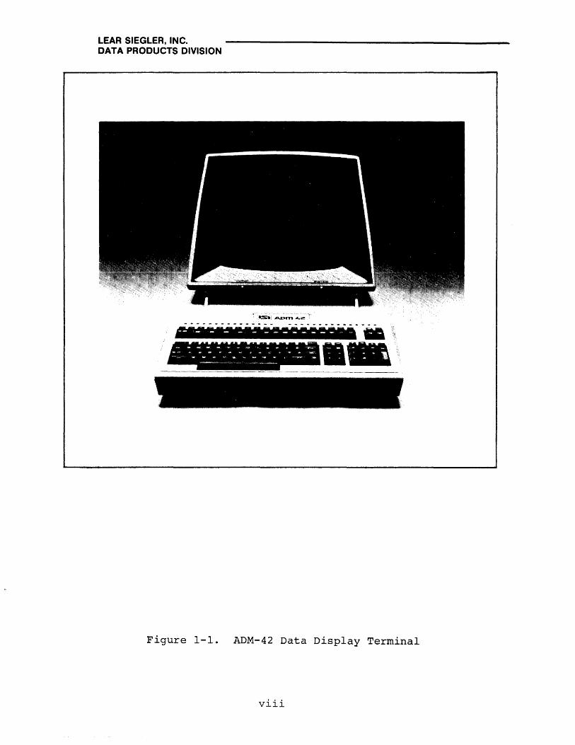
Figure 1-1. ADM-42 Data Display Terminal
viii
LEAR SIEGLER, INC. DATA PRODUCTS DIVISION
SECTION 1
GENERAL DESCRIPTION
1.1 INTRODUCTION
This section contains a description of the primary functions of the Lear Siegler ADM-42 Data Display Terminal (see figure 1-1), along with physical dimensions, specifications and ranges, and operating features.
1.2 PURPOSE AND USE
There are numerous applications of the ADM-42, all involving the transfer of data. Data transfer, in some applications, may be almost exclusively unidirectional; either from the ADM-42 to the computer, or from the computer to the ADM-42. A more frequent application of the ADM-42, however, is one in which an operator communicates with a computer, and the computer responds in accordance with its stored program.
The .. ADM-42 has the following general capabilities:
• Full 128 ASCII character set with 80 x 25 character display
• User controlled status display on Line 25
• Full ADM-2 compatibility
• 15 transmission rates
• Conversational and Block Mode transmission
• Data key roll-over protection
• 39-Key special functions keyboard
• lS-Key numeric keyboard
• Separate cursor control keys
• Up to eight full pages of memory
1-1
LEAR SIEGLER, INC. DATA PRODUCTS DIVISION
• Program Mode
• Special control character sequences
• Full editing, formatting, and protected fields capabilities
• Variable 10-or II-bit word structures
• Dynamic behavior fpersonality) modification
• Selectable refresh rate
• Reversed, blinking, and blanked fields, with underlining
• Standard RS-232-C interface, RS-232-C extension, and 20-ma current loop; optional line printer, polling, and synchronous interfaces
1. 3 OPERATIONAL DESCRIPTION
The ADM-42 is a microprogram-controlled device which provides a means of communicating with a remote computer, and which allows the user full control of the content and format of data entered by means of the keyboard. Figure 1-2 illustrates the flow of data through the functional areas of the ADM-42.
The Standard ADM-42 consists of a power supply, keyboard, control section (CPU), video logic and control, CRT display, configuration control switches, and external interface logic. The interface logic permits the following interfaces: an RS-232-C or 20-ma current loop interface through the MODEM port; daisychained devices through the EXTENSION (and MODEM) port; an optional polling interface through the MODEM port; a parallel or serial printer interface through the AUXILIARY port; and a data set or teletype interface through the SYNCHRONOUS port.
1.3.1 Regulated Power Supply
The ADM-42 power supply is a 65-wat~ regulated and unregulated power supply mounted on a printed circuit borad which is adjacent to the main printed circuit board assembly. Three regulated dc voltages are furnished for use by the CPU: +5 volts, and ±12 volts. Unregulated +5-volt dc power is also supplied and for keyboard circuits. The power supply can accept line voltage inputs of 115 Vac or 230 Vac (with 230 volt transformer and connections.)
1-2

LEAR SIEGLER, INC. DATA PRODUCTS DIVISION
KEYBOARD
DAI-A AND CONTROL ..
POWER SUPPLY
CONTROL SECTION
(CPU)
....
25 LINES CRT DISPLAY 80 CHARACTERS
SCREEN PER LINE
DATA AND CONTROL
DATA
SYSTEM DATA CONFIGURATION I-----------t ... AND CONTROL
SWITCHES
VIDEO LOGIC AND CONTROL
DATA AND CONTROL .1 EXTERNAL
INTERFACE
, , OPTION PCBA
SERIAL OR PARALLEL
ASYNC PORT
SERIAL OR PARALLEL PRINTER
SYNCHRONOUS PORT
DATA SET OR
TELETYPE
1_" . .:;..
DATA • AND CONTROL
MODEM (RS-232-C)
PORT
r- - -----20MA CURRENT
LOOP
COMPUTER OR
MODEM
... DATA "
~AND CONTROL EXTENSION (RS-232-C)
PORT
, r - --;.... ----, f f I DAISYCHAIN f I DEVICES I J I L ____ -1
Data Flow Block T'\.: ____ _ u..L.al::;jl..aUl
1-3

LEAR SIEGLER, INC. DATA PRODUCTS DIVISION
1.3.2 Keyboard
Data to be processed by the terminal is either from the keyboard or is sent from the remote computer. Keyboard entry is made using one of the 118 keys on the keyboard. Each keystroke is encoded into a parallel number which the CPU uses to determine the eventual ASCII'or operational character to be developed and used. Accompanying the character is a keystroke which alerts the program that a character is to be input from the keyboard.
1.3.3 Control Section (CPU)
The Control Section (CPU~ contains the microprocessor and various integrated circuits which control all the operations of the ADM-42. These operations include: timing and control, data handling and storage, interpreting and responding to control commands from the keyboard and the computer, video control, I/O interfacing, and status control.
Data entered from the keyboard is placed on the Data Bus and sent to the CPU section, which contains the microprocessor and various other integrated circuits and switches. The CPU, executing a stored read only memory (ROM) program, decodes the input data and reformats it into data and control instructions for the video logic and control section.
1.3.4 Video Logic and Control
The Video Logic and Control section contains the display logic needed to drive the CRT, 4k of random access memory (RAM), and character generation circuits, as well as the video logic and IS-inch monitor. The monitor screen can display 25 lines (including one status line) of data containing as many as 80 characters per line. Data from the CPU is written into the video RAMi control instructions from the CPU cause the contents of the RAM to be periodically displayed on the CRT screen.
1.3.5 External Interface
Data and control information from a remote computer is routed through the MODEM port to the external interface section, and then to the CPU. The CPU causes data to be displayed on the CRT in the same manner as the keyboard data. The interface contains the logic circuitry appropriate for interfacing with RS-232-C point-to-point signals, 20-ma current loop signals, modem logic, and daisychained devices. An option PCBA provides circuits for an RS-232-C serial or parallel printer interface and for a data set or teletype (TTY) interface. The external interface also contains the baud rate clock and baud rate switches which permit the ADM-42 to receive or transmit data at selected baud rates from 50 to 9600 baud.
1-4

LEAR SIEGLER, INC. DATA PRODUCTS DIVISION
The ADM-42 transmits data by retrieving data from the video RAM and placing it on the Data Bus for routing to the cpu. The cpu reformats the data and routes data and control information to the external interface section over the Data Bus. External interface logic is used to prepare the data and control information for transmission to the appropriate device connected.
1.3.6 System Configuration Switches
Several banks of system configuration switches are provided to control various attributes and characteristics of the ADM-42. The switches are mounted on the standard and option PCBAs. The characteristics thus controlled include: mode of transmission/ reception, parity, word structure, refresh rate, cursor/display attributes, and polling addresses and modes.
1. 4 PHYSICAL DESCRIPTION
The ADM-42 Data Display Terminal is a complete operational unit. The terminal consists of three major assemblies: electronics unit, keyboard unit, and monitor unit. The electronics unit contains all the basic logic circuitry, baud rate switches, power supply, fan, cabling, and interface connectors. The standard and option PCBA's are contained in this unit. At the rear of the unit are located the interface connectors, RESET switch, ON/OFF switch, fuse, and power cord.
The keyboard contains 118 alpha numeric and special character keys which are generally arranged like a standard typewriter. The keyboard and the accompanying solid state logic circuits are used to generate the 128 ASCII characters in the standard ADM-42 character set. Included in this character set are 32 control characters which can be produced by special key operations. A roll-over feature is incorporated in the keyboard to protect against mis-keying. (If a second key is pressed before the key first pressed is released, the second code will not be transmitted until the first key has been released.) The keyboard may be physically moved several feet away from the main terminal without interrupting operations.
The PCBA(s) containing the microprocessor, memory, and logic is (are) the source of all control and coordinating activities in the ADM-42. These circuits transfer keyboard information into the display memory, display the contents of the memory on the CRT, recognize control commands typed at the keyboard, and execute the commands. The circuits also supervise communications to and from the remote computer and recognize control commands received through the terminal interfaces.
1-5
. LEAR SIEGLER, INC. DATA PRODUCTS DIVISION
The monitor is a fully transistorized unit featuring printed circuit board construction. The display screen is a IS-inch diagonal cathode ray tube (CRT) similar to that of a black-andwhite television receiver. The display is a high resolution matrix of 80 x 25 characters consisting of large letters, numbers, and other symbols. Information on display is refreshed at 50 Hz or 60 Hz, depending on the line frequency. (an internally located DIP switch must be appropriately set at installation.) Brightness and contrast are individually adjustable by means of controls on the monitor. The monitor may be physically moved several feet from the main terminal without interrupting operations.
The power supply, providing three regulated and one unregulated dc voltages for use by the main PCBA circuits, is contained on its own printed circuit board and mounted near the main PCBA. The four outputs have a total power rating of 63 watts. The ac input voltage may be either 115 volts or 230 volts at 50 or 60 Hz. DC output voltages are as follows:
• +5 volts at 1 ampere maximum load, unregulated
• +5 volts at 9.0 amperes maximum load, with +5% regulation and overload protection
• +12 volts at 0.75 ampere nominal load, with +5% regulation
• -12 volts and 0.4 ampere nominal load, with +5% regulation
1.5 SPECIFICATIONS
Table 1-1 lists the leading specifications for the ADM-42. In addition, several operational features, such as various transmission modes, character format, word structure, and configuration control are discussed in the paragraphs that follow.
1.5.1 Transmission Modes
Various transmission modes are utilized by the ADM-42; these include the Block and Conversation Modes. The Block Mode permits the operator to edit and perform off-line operations, and then come on-line for the actual transmission of the data. Processing time is limited to the actual transmission time only. In the Conversation Mode, either full-duplex or half-duplex operation is possible. Block and Conversation Modes are selected through the escape (ESC) sequences, or by using the CONV MODE key.
1-6

LEAR SIEGLER, INC. DATA PRODUCTS DIVISION
Table 1-1. ADM-42 Specifications
SPECIFICATION DESCRIPTION
Input Power:
Standard
Optional
Power Dissipation
Operating Temperature
Relative Humidity
Altitude
Physical Dimensions
Weight
CRT Screen Size
Display Format
Character Set
Refresh Rate
Cursor:
Format
115 volts +10%, 50/60 Hz; Single Phase; 3-wire
230 volts +10%, 50/60 Hz; Single Phase; 3-wire
65 watts, nominal (rated: 0.75A at 120 volts)
o 0 Between 41 F (5 C) and 1220 F (50o F)
From 5% to 95% non-condensing
Up to 10,000 feet (3048M)
18.0 in. (45.72 cm) High X 18.9 in. (48.0 cm) Wide X 25.38 in. (64.51 cm) Deep
50 pounds (22.67 Kg)
15 inches (30.5 cm) diagonally
80 characters per line x 25 lines; 8 pages, maximum
128 ASCII characters (with 32 control characters); upper/lower case fonts; 9 x 11 dot matrix pattern
50/60 Hertz (depending upon line frequency)
Reverse video rectangle (10 x 12 dot matrix)
1-7
LEAR SIEGLER, INC. DATA PRODUCTS DIVISION
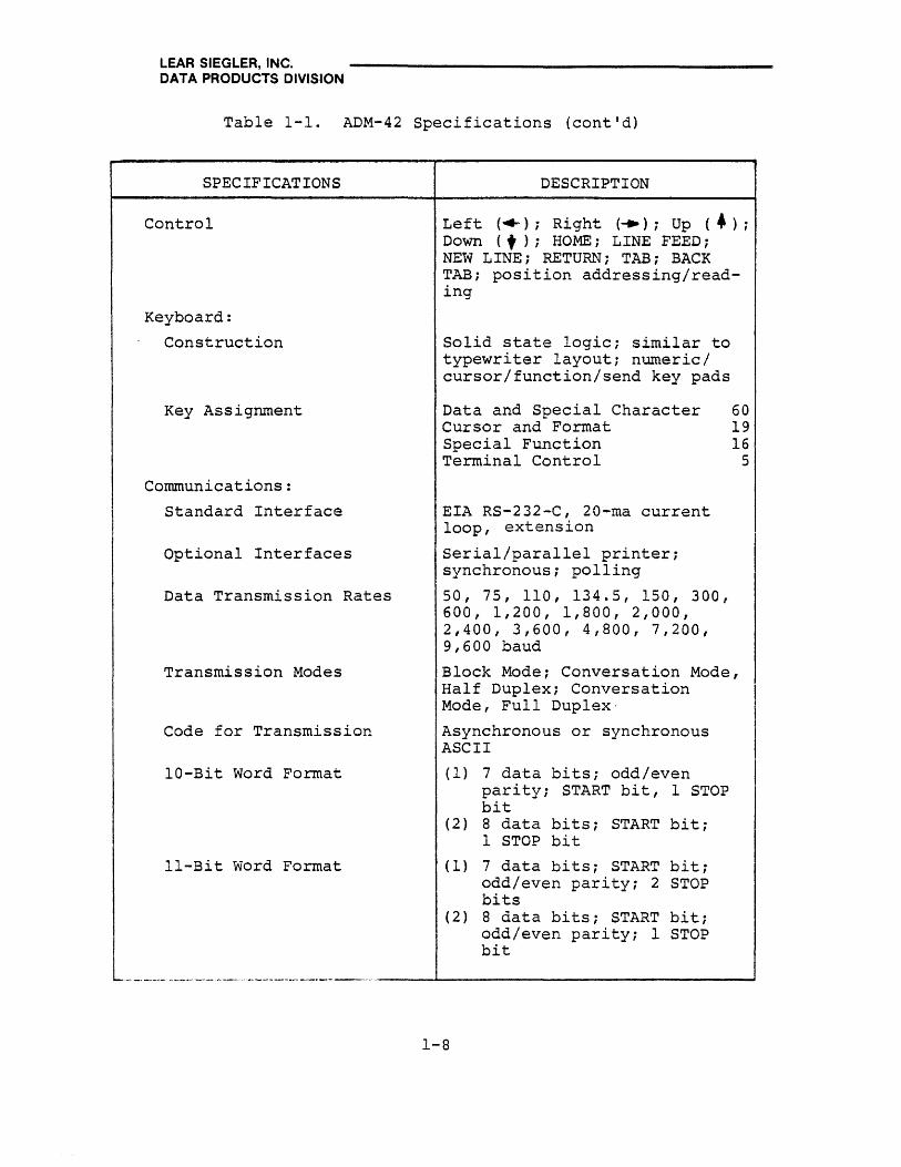
Table 1-1. ADM-42 Specifications (cont'd)
SPECIFICATIONS DESCRIPTION
Control Left ( ..... ); Right (-+); Up (.); Down (t); HOME; LINE FEED; NEW LINE; RETURN; TAB; BACK TAB; position addressing/reading
Keyboard:
Construction
Key Assignment
Communications:
Standard Interface
Optional Interfaces
Data Transmission Rates
Transmission Modes
Code for Transmission
10-Bit Word Format
II-Bit Word Format
Solid state logic; similar to typewriter layout; numeric/ cursor/function/send key pads
Data and Special Character Cursor and Format Special Function Terminal Control
EIA RS-232-C, 20-ma current loop, extension
Serial/parallel printer; synchronous; polling
50, 75, 110, 134.5, 150, 300, 600, 1,200, 1,800, 2,000, 2,400, 3,600, 4,800, 7,200, 9,600 baud
60 19 16
5
Block Mode; Conversation Mode, Half Duplex; Conversation Mode, Full Duplex-
Asynchronous or synchronous ASCII
(1) 7 data bits; odd/even parity; START bit, 1 STOP bit
(2) 8 data bits; START bit; 1 STOP bit
(1) 7 data bits; START bit; odd/even parity; 2 STOP bits
(2 ) 8 data bits; START bit; odd/even parity; 1 STOP bit
...... __ .----- ........... _-_ ..... _ ........ _--_ ..... _--_. __ . __ ._ ..... _--'-----------------~
1-8
LEAR SIEGLER, INC. DATA PRODUCTS DIVISION
Block Mode
In the Block Mode, infor.mation is transmitted and received as complete messages or blocks of data (compared with character-bycharacter operation in the Conversation Mode). The characters are stored and displayed, but are not automatically transmitted. The operator or the computer enters the complete message, up to two full pages in length. After the message has been completed, the operator can edit the information. The operator may send the message line by line (SEND LINE) or by the page (SEND PAGE), as well as the complete message (SEND MSG). If desired, the operator may select only part of the information for transmission. This is done by inserting control characters in the copy during the editing phase. These control characters signal the start of message and the end of message. Then when the SEND MESSAGE COMMAND is issued, only the copy between the control characters is transmitted.
The Block Mode, besides providing the edit capability, also permits faster transmission of large blocks of data than can be obtained in the Conversation Mode. It also permits more efficient utilization of the remote computer and data transmission lines. The ADM-42 can operate off-line when the information is being typed and edited, and come on-line only during t'he actual transmission. Then too, the baud rate can be increased, which results in a reduction of computer time (to receive the ~nIormation) , as compared to having the operator send the same message in the Conversation Mode.
Conversation Mode, Half-Duplex
In this mode, the ADM-42 can send and receive information to and from the remote computer, but in only one direction at a time. Characters are displayed, and simultaneously transmitted, one character-at-a-time as they are typed at the keyboard. Received characters are displayed as they are received.
Conversation Mode, Full-Duplex
The ADM-42 can transmit and receive information in both directions simultaneously in full-duplex operation. Characters are transmitted as they are typed, but are displayed only on reception. In order for transmitted characters to be displayed in full-duplex operation, they must be echoed from the remote computer back to the ADM-42.
1-9

, LEAR SIEGLER, INC. DATA PRODUCTS DIVISION
1.5.2 Character Format
The standard ADM-42 character set contains 128 ASCII characters, 32 of which are control characters that require special key operations to produce from the keyboard. (See figure 1-3) The entire character set can be displayed on the CRT screen if transmission from computer or keyboard is preceded a command placing the terminal in Program Mode.
1.5.3 Word Structure
The ADM-42 can transmit and receive data characters in anyone of the asynchronous character formats shown in figure 1-4. These word format codes are selected by means of DIP switches located internal to the ADM-42.
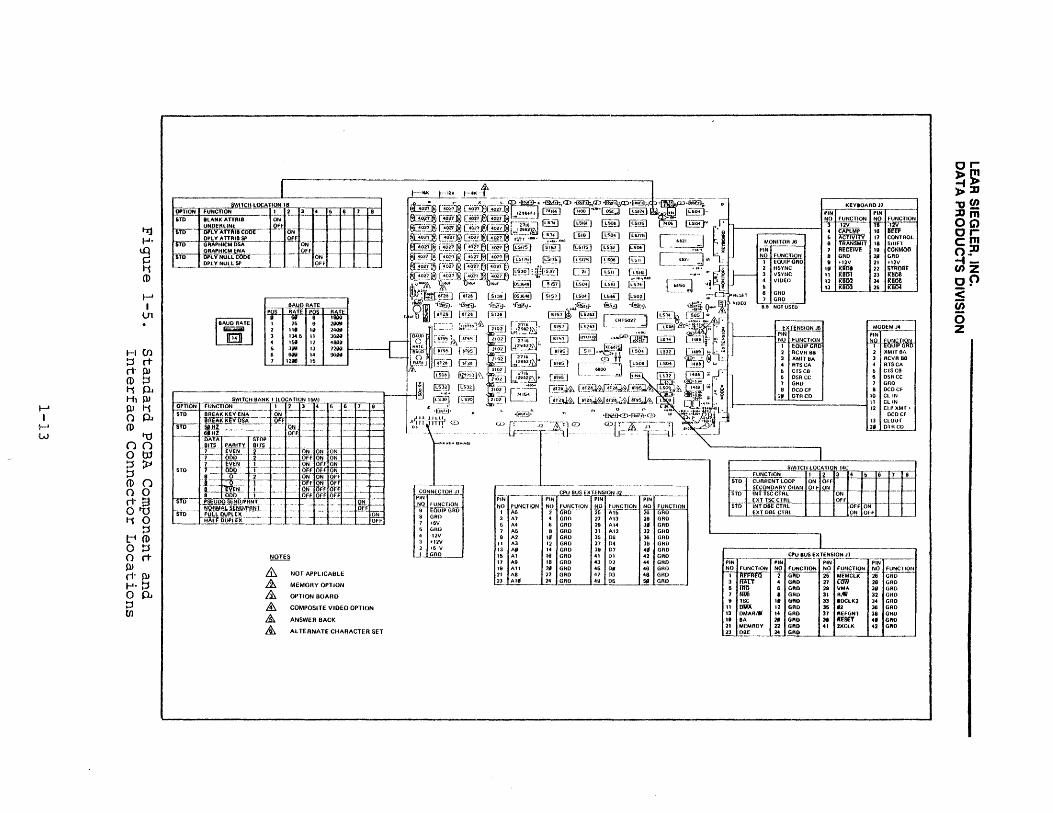
1.5.4 Configuration Control
Three sets (banks) of DIP switches are provided on the standard PCBA which can be used to establish or change certain operational characteristics of the ADM-42. Figure 1-5 shows the location of these switches, whose functions are described below.
Switch Location IB
There are four active switches at location lB:
• SW 1 determines the characteristics of the video field designated by a video attribute control code: ON causes the field to be blank or underline, depending upon which control code was selected; OFF causes the field to be underlined.
• SW 2 determines how the selected video attribute control codes will be displayed on the CRT: ON causes the codes to be displayed as codes; OFF causes 'the codes to be displayed as spaces.
• SW 3 controls the Graphic Mode attribute (future).
• SW 4 determines whether ADM-42 null codes will be displayed as null codes (ON) or space codes (OFF).
Switch Location 15M
There are seven active switches at location lSB:
• SW 1 controls the operation of the keyboard BREAK key: OFF disables the key; ON enables the key.
• SW 2 controls the monitor refresh rate: OFF for 60 Hz line frequency; ON for 50 Hz frequency.
1-10

I-' I
I-' I-'
tl1 ~
~ rn o CD !:l C-L 1-'. !:l lQ
~ (f) () H H
() o C-L CD en
00 NUL
01 SOH
02 STX
03 ETX
04 EaT
05 ENQ
06 ACK
07 BEL
08 8S
09 HT
0A IF
08 VT
0G FF
00 CA
0E SO
0F Sf
r-----r-----+-----r-----r-----r-----~--~~.--~~----~--~~----r__----.--.--+-----+-----+---~ 19 1A 18 1C 10 1E 1F 10
OLE
20
30
40
50
60
79
11 OCl
21
31
41
51
61
71
12 OC2
22
32
42
52
62
72
13 OC3
23
33
43
53
63
73
14 OC4
24
34
44
54
64
74
15 NAK
25
35
45
55
65
75
16 SYN
26
36
46
56
66
76
17 ET8
27
37
47
57
67
77
18 CAN
28
38
48
58
68
78
EM SUB ESC FS GS AS US
29 2A'-+--2-8--+--2-C--+--2-0--+--2-E--i--2~F~~
39 3A 38 3C 3D 3E 3F
49 4A 48 4C 40 4E 4F
59 5A 58 5C 50 5E 5F
69 6A 68 6G 60 6E 6F
79 7A 78 7C 7D 7E 7F
CTRL FUNCTIONS
ESC ~FUNCTIONS
or»om -tl> l>::O "Of/) :Dm OG) orem o~ -tf/)Z
of> <: (i)
5 Z

LEAR SIEGLER, INC. DATA PRODUCTS DIVISION
DIP SWITCH WORD STRUCTURE
WORD FORMAT CONFIGURATIONS
BIT BIT BIT BIT BIT BIT BIT BIT BIT BIT BIT
SW5 SW4 SW3 ~ 1 2 3 4 5 6 7 8 9 1~
r
I Eleven-Bit Word
ON I St even with Even Parity ON ON a ACTIVE BITS = 1 OR fI stop stop and 2 STOP Bits
rt parity
i r I I I I
I St I I I I I ,
Eleven- Bit Word odd with Odd Parity ON I ON OFF a ACTIVE BITS = 1 OR ~ stop stop and 2 STOP Bits
rt parity
i I I I I t I
I I I I I I I
V( Ten-Bit Word St even with Even Parity ON I OFF ON a ACTIVE BITS = 1 OR .0 stop and 1 STOP Bit
rt parity
I I I I I I I I I I I I -, I
[X Ten-Bit Word I OFF
St odd with Odd Parity ON OFF a ACTIVE BITS = 1 OR 0 stop and 2 STOP Bits
r t parity I I I I I I I I I , I
Eleven- Bit Word St always with No Parity OFF ON ON a ACTIVE BITS = 1 OR ~ 0 stop stop and 2 STOP Bits I r t
I I I I I I I
! I I I I rx Ten-Bit Word St always
with ~o Parity OFFI ON OFF a ACTIVE BIT S = 1 OR 0 0 stop and 1 STOP Bit
rt
I I I I I , I
OFFloFF
I I I I T 1 E it'veo- Bit Word St always I.I:ith Even Parity ON ACTIVE BITS = 1 OR ~ 0
even stop :.l
parity :md 1 STOP Bit I r t
I 1 L I I I I I I I I I r always EIE'ven-Bit Word St 0 odd with Odd Parity OFF OFF OFF a ACTIVE BITS = 1 OR ~
parity stop and I STOP BIT
ft
I I I I I I I
Figure 1-4. Word Format Codes With DIP Switch Configurations
1-12
I-' I
I-' W
.-. I
Ul
HUl ::s rt ri- PJ CD ::s t-;$.).J H1PJ PJ t-; O$.).J CD
'U no o tJj !:1 ~ ::s CD 0 o 0 rI· a 0'"0 t-; 0
::s t-t CD o ::s o rt PJ rI· PJ ..... ::s op. ::s til
~~~TIO~N~F~U~NC~T~ION~WUIT~CHIJL~OC~A~Tl~I~~I~~-Y.~..-~-r.~r.-Tft~ 8TO IILANK ATIRI8 ON
fO ~Wt.aCbDC ~fffoN I--I---I--+-II--+-.-l
TO
STO
sro
~:~~I~~~R~'h~ 1-- QfF ON+-- -.~-+---j..--I GRAPHICM ENA , OFr OPiVNOLLooor---- - -- oii OPl Y NULL SP___ -l_J.:O::..F:..Jf __ -'--_-'-_l..~
M 8 I 2 3 4 6 6 1
OAUO RATE RATf POS AAT~ : a ~:: 9 III liII 24l1li 134,6 11 36"" I Sill 12 -6l1li 3111! 13 12W 6W I- 00""
12l1li 16
NOT APPLICABLE
MEMORY OPTION
OPTION BOARD
COMPOSITE VIDEO OPTION
ANSWER BACK
AL TERNATE CIlARACTER SET
r-------
PiN --_.-._--_ .. -
NO fUNCTION 'T AS'----
3 A7 6 A4 1 A5 9 A2
II A3 13 All 15 Al 17 A9 19 All 21 A8 23 AliI
---~---
PIN flli!!!!§t>!~ffi"~ NO fUNCTION -2- GRO---
4 GAO 6 GAO a GRO
III GAO 12 GAO 14 GAD 16 GRO 18 GilD 2fII GRD 22 GAO 24 GAO
NO 26 21 29 31 35 J7 39 41 43 45 47 49
fUNCTION Al5'--
All AI4 AI2 06 04 07 01 I n O. 03 ~6
PIN
till,~ 26 GRO 28 GAD 311 GRO 32 GRD J6 GRO 30 GAO 411 GAD 42 GAO 44 GHO 46 GHo 48 GAO 5jl~
--KEY'OARD J1
PI~ PI~
~] ~O fUNCTION NO FUNCI-ION "3 -12V 16" -IW-
4 CAPlMP 16 am 6 Ac'fiVi'TY 11 CONTROL
MONITOA J6 6 'fliAiiSMIT 18 Sinfl PIN 1 A£l:1ffi7E 19 CCiNMIlO NO FUNCTION 8 GRD 28 GRD
1 EQUIPGRD \I t12V 21 il2V q ]- 2 HSYNC III IOO1t 22 STlfOIIt 3 VSY/lC 11 Ram 23 RliDil 4 VIDEO 12 KIm} 24 KII06 6 13 Kiffij 26 Kiifj4
C): ;".ESET 6 GRO
@} VID[O '-fa ~~~USEO &
P ~-----
}-- EXTENSION J6 MODEMJ4 PIN
~ "' . ~"~ *1~hWb ~ E I 2 RCVR 8a 2 XMITOA 3 XMlr UA 3 RCVR 00 .. '
4 RTseA 4 RISCA
til 6 crsco 6 C'ISCB 6 OSR CC 6 OSA CC 7 GAD 1 GAD 8 DCOCF a DeoCF
2" OTRCD 10 CI.IN II CliN
~L' 1--' 12 CU'XMr ... DeDCf ., ~ 13 CLOUT
2f11 01A CD
PIN 'IN ~~~XT:~S~~_ -,-----
PIN NO FUNCTION NO fUNCTION NO fUNCTION NO fUNCTION
I I~ 2 Gfto- '26 MEMCi:K '26" G~ 3 4 GRO 27 [OW 28 GAO 5 11m 6 GilD 28 YMA 3fII GAD 1 fm1 • GRO 31 R,'JI 32 GHo 9 TSC II GilD 33 IOCLK2 34 GRO
11 OW; 12 GAO 3S .a 38 GRO 13 OMAAiW 14 GRD 31 IIEfGNT 38 GRO It BA 21 GilD 31 ArsrT 41 GilD 21 MEMAOY 22 GilD 41 2XClK 42 GilD II oaf 24 GAO

LEAR SIEGLER, INC. DATA PRODUCTS DIVISION
• SW 3, 4, 5 control the MODEM interface word structure, in accordan6e with the settings shown in figure 1-4.
• SW 7 ON enables Pseudo Print control; OFF enables Normal Print control.
• SW S ON establishes CONV MODE Full Duplex operation; OFF establishes Half Duplex operation. Either setting may be dynamically changed by an escape sequence.
Switch Location l4C
There are five active switches at location l4C:
• SW land SW 2 control the current/loop/secondary channel interface, as follows:
SW 1 ON and SW 2 OFF = Current loop enabled
SW 1 OFF and SW 2 ON = Secondary Channel enabled
SW 1 and SW 2 OFF = Current loop and Secondary channel disabled
• SW 3 ON enables internal TSC (Tri state bus control) i SW 3 OFF enables external TSC.
• SW 4 and SW 5 control the operation of the data bus extension (DBE) logic, as follows:
SW 4 ON and SW 5 OFF = External DBE control
SW 4 OFF and SW 5 ON = Internal DBE control
SW 4 and SW 5 OFF = Not defined
1. 6 ADM-42 OPTIONS
The ADM-42 can be provided with a large number of independently controlled and executed optional features, each requiring additions and/or alterations to the standard PCBA. (See figure 1-6). The following options are available.
Option No.1
Not applicable
Option No. 2 - Data RAM Extension
This option provides the capability of extending the basic RAM in the CPU an additional SK, 12K, or 16K by the installation of the appropriate number of 4K RAM chips.
1-14

I-J:j 1-'-to ~ 11 CD
f--A I
0'\
1--10 !Jro ri- n-CD 1-'-t1 a
I-' l-tl !J I AI ,~ o '1j U1 (DO
to n ~ a !JO !J a CD S oro rta o !J t1 CD
!J t-in-a o AI AI !J n-P.t 1-''' a !J Ul
SWiTCH Uttt!!I.l.!llli .J!!llilL. 1J,l£1iliQ!i POLLING· hi ADOA 5 5L POl.lING 21)\1 AQOA 6 6l GROUP POll· hi ADDA 1 8l GROUP POll 2nd ADDU 8 9l GAOuP Sf LfCT 9 111
:~N~[~~~--~-';-Ii - 6N ~- - _~c 5-_-f!'--+"--__ .t~B'_--._j
Bln------ .-- -:1.-- Of ON
BIT 4
8ITG-- --
POll 161 ENA POll lSI OSA POllCOMBtJr·
ENA (6,
G~.rnENA GAP 11&8) OSA GAPseTENA-~i~~_ -I
-- OfF - (IN' --
i'jFf -- ---- -~ ON ------:- ~F·
ON OFF .-
-- F· • N
Off
PARALLH PATA PORT
ASYNC PATA PORT
SYNCHRONOUS pOln
POl.lING AOOR~SS
SOfTWARE AAM;
lK.7K.3K
PROGRAM PROM
BUS EXUNSION
I=[~~ ~~ EXTENSION 12
PIN PIN
.!'Q. fU~:!!~",! NO fUNCTION
A6 2- (iAO"-A7 . GRO A4 6 GAO A5 D (jAO A2 Ie GRD
II AJ 12 GAD 13 ,.. 14 GRO lfi Al 16 GAD 17 AD 18 GAO lu All 2~ GRO 21 AD 22 GRII 23 All 24 GRO 26 AI5 26 GRO 21 AI3 28 GRO 29 AI. J, GAO 31 AI2 32 GRO 36 06 36 GAD 37 04 38 GAD 39 07 411 GRD 41 01 42 GRO 43 02 44 GUO 45 011 46 GAO 47 03 48 GRO
~ OS 51 GAO
~:PU OUS EX TI: NSION J3
PIN PIN NO fUNCTION NO FUNCTION l1itFfitil- 2 Gno 3 HALT 4 GRO 6 iliO 6 GAO 7 Nl.lI 8 GRO 9 rs<: I' GAO
II OlofA 12 GAD 13 OMARiW 14 GRD 19 SA 211 GAD 21 MEMHOY 22 GRO 26 M£MClK 26 GAD 27 ["OW 28 GAO 29 VMA 3g GRO 31 RIW 32 GRD 33 OOCLK2 34 GAO 36 12 36 GRO 37 RHGNl 36 GRO 39 iiieSEf .- GRO ., 1~_ 42 GAO
r--~'-- --~ _ BUS ~~!~~~~ON .:'!~_
~~ fUNCflON NO ~~~el~~ 05------ -~.
b 03 6 GRD 7 01 8 GAO 9 02 14 GAD
II 01 12 GRD 13 07 14 GRO 16 06 16 GAO II AI2 16 GAO 19 AI6 211 GAD 21 A8 22 GAO 23 A9 24 GAO 26 AB 26 GAD 27 A2 26 GAD 29 A4 3' GRD 31 A6 32 GRO J3 MEMAOY 34 GnD 35 RHGNT 36 GRO 37 BOClK2 38 GRO 39 VMA 4, GRO 41 MEMCII( 42 GRO 47 DMARI'ii 48 GRO 49 TSC 61 GRO
ponT Jb PfN NO FUNCTION T EQUlp·GRO
2 jifoAT;;; 3 PT OAf A 5 CTS AUK
6.8 PRTS 1 GRU
19 peTS
211 !'~~._
or l>~ ~:D -o(/) :D-O~ or em o}J ..... -cnz on <: iii o z

LEAR SIEGLER, INC. DATA PRODUCTS DIVISION
Option No. 3 - Option Board Installation
This option basically is the installation of an option PCBA in addition to the standard PCBA in the ADM-42. Once installed, along with the appropriate hardware required to interconnect the various logical bus extensions, several other sub-options are available, as follows:
• Parallel Printer Port option provides the appropriate logic and hardware for connecting a parallel printer. Included in this option is the ability to program the port so that the printer connected to the port may be controlled directly from the host computer without otherwise affecting ADM-42 operation.
• Asynchronous Serial Printer Port option provides the same capabilities as the parallel port option, except that a serial printer may be connected.
• Synchronous Port option provides the appropriate logic and hardware for the connection of a data set (such as a Bell System Data Set) or teletypewriter to the ADM-42.
• Polling Address option provides the appropriate logic and hardware to accommodate the following polling modes: Select, Group Poll, Sequential Select, Group Select, Fast Select, Broadcast Select, and Multi-Point Contention.
• Programmable Function Keys option provides the ability to store either 32 or 64 characters under any function key FI through Fl6, shifted or unshifted.
Option No. 4 - Composite Video
The composite video option converts the CRT's video and sync signals into a composite video output which is then routed to the rear-panel COMPOSITE VIDEO output connector. Data can then be transmitted to a compatible composite video monitor located up to 1000 feet away, through a single coaxial cable. The ADM-42 can function in its normal capacity at the same time it is serving as a control terminal for a remote monitor.
Option No. 5 - Answer Back Option (Future)
The automatic answer back option provides terminal identification and allows the ADM-42 to respond to an ENQ input from the computer with the answer back message. The answer back message will be displayed as it is being transmitted, if the terminal is in Conversation Mode, Half Duplex.
1-16

LEAR SIEGLER, INC. DATA PRODUCTS DIVISION
Option No. 6- Optional Character Generator Set
This option, when combined with optional keyboard arrangements makes it possible to display and print data in many different fonts and languages. Languages which are currently available include German, United Kingdom, and Scandanavian.
Option No. 10 - 230V 50 Hz Power Input
Standard input power for the ADM-42 is 115 volts ac at 60 Hz. 230 Vac power at 50 Hz is readily accommodated by changing the power supply trans.former, the monitor supply transformer, and the main logic board connections. Internal DIP switches establish the video refresh rate at 50 or 60 Hz, depending upon line frequency.
1. 7 RELATED DOCUMENT
ADM-42 Maintenance Manual DP 309
1-17/18

LEAR SIEGLER, INC. DATA PRODUCTS DIVISION
SECTION 2
INSTALLATION
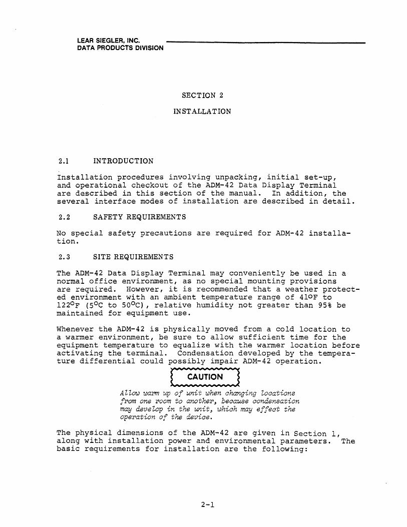
2.1 INTRODUCTION
Installation procedures involving unpacking, initial set-up, and operational checkout of the ADM-42 Data Display Terminal are described in this section of the manual. In addition, the several interface modes of installation are described in detail.
2.2 SAFETY REQUIREMENTS
No special safety precautions are required for ADM-42 installation.
2.3 SITE REQUIREMENTS
The ADM-42 Data Display Terminal may conveniently be used in a normal office environment, as no special mounting provisions are required. However, it is recommended that a weather protected environment with an ambient temperature range of 4loF to l220 F (SoC to SOoC), relative humidity not greater than 95% be maintained for equipment use.
Whenever the ADM-42 is physically moved from a cold location to a warmer environment, be sure to allow sufficient time for the equipment temperature to equalize with the warmer location before activating the terminal. Condensation developed by the temperature differential could possibly impair ADM-42 operation.
~ Allow warm up of unit when changing Zocations from one room to another~ because condensation may develop in the unit~ which may effect the operation of the device.
The physical dimensions of the ADM-42 are given in Section 1, along with installation power and environmental parameters. The basic requirements for installation are the following:
2-1
LEAR SIEGLER, INC. DATA PRODUCTS DIVISION
• Table or desk for mounting
• Standard three-pronged lIS-volt (230-volt) power outlet
• Data signal interface connection to the computer, modem, serial printer, or other auxiliary device. If connection to a remote computer is desired, a modem or data set is required.
2.4 UNPACKING AND INITIAL INSPECTION
Each ADM-42 unit is packed using standard practices for the shipping of electronic equipment. Every precaution is taken to ensure that each unit is complete and ready for installation at the customer site. However, it is recommended that each unit be inspected upon receipt for transit damage. Inspect for exterior evidence of damage. Contact the carrier and LSI immediately if damage is evident, specifying the nature and extend of the damage (if known).
If there is no apparent shipping damage, open the shipping carton and remove the items, checking them against the shipping list to verify the contents of the carton. Contact LSI immediately in the event of a packing shortage. Check to verify that the serial nw~ber of the unit corresponds to that shown on the invoice. Visually inspect the exterior of the enclosure for evidence of physical damage which may have occurred in shipment.
Check the hardware to determine if any assemblies or screws have been loosened during shipment. Tighten as required. Inspect for dust or foreign material which may impair electrical contact when cable connections are made. Vacuum to remove any loose dirt. Remove the bubble packing from the interior of the terminal.
2.5 INITIAL PREPARATION
2.S.1 Line Voltage Selection
The ADM-42 is shipped connected for either lIS-volt or 230-volt operation, as specified in the purchase order. Any change in line voltage requires circuit changes in the ADM-42 which can be accomplished only by authorized LSI maintenance personnel.
2.S.2 Configuration Control Switch Settings
A number of internal DIP switch banks are provided for encoding selected system configuration characteristics. The locations of these switch banks and their functions are shown in the component and interface connections illustrations for the standard and option PCBA's in Section 1.
2-2

LEAR SIEGLER, INC. ,DATA PRODUCTS DIVISION
2.6 INTERFACE INFORMATION, STANDARD PCBA
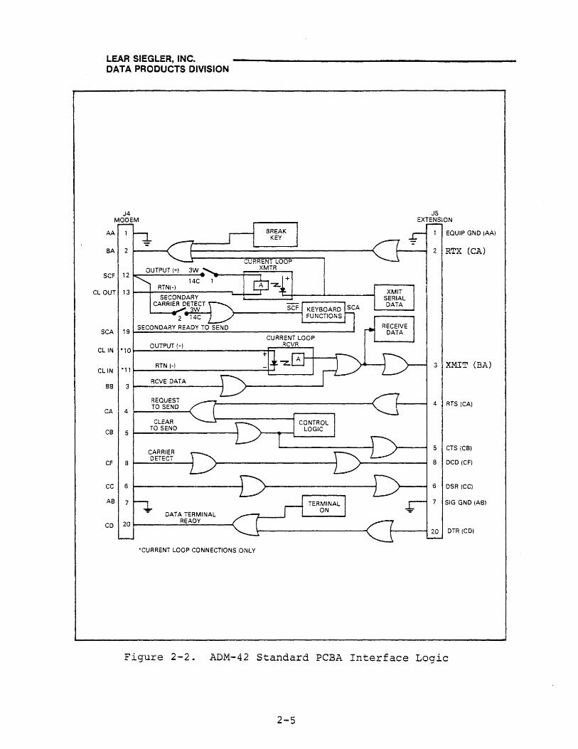
The ADM-42 using the standard PCBA may be cabled directly to a local computer or other auxiliary device; or it may be connected via telephone data lines to a remote computer located anywhere in the world. Remote computer connections require the use of a modem or data set. Figure 2-1 shows several typical ADM-42 interfaces, while figure 2-2 shows the ADM-42 interface logic associated with the interfaces.
2.6.1 MODEM Port Interface
The MODEM port interface is used to connect the terminal directly to a computer, modem or data set, or to a computer or device in a current-loop application.
2.6.2 EXTENSION Port Interface
The EXTENSION port interface enhances the standard RS-232-C capabilities of the ADM-42 to permit daisychaining of several terminals or other auxiliary devices.
2.7 INTERFACE INFORMATION, OPTION PCBA
The ADM-42, using the option PCBA in addition to the standard PCBA, may be cabled directly to an asynchronous serial or parallel printer; or to a synchronous device. Whenever these devices are used, bus extension connections must be made between the option PCBA and the standard PCBA, as well as to the remote computer. (See figure 2-3 for bus extension connections. )
2.7.1 PARALLEL PRINTER Port Interface
The PARALLEL PRINTER interface is used to connect the ADM-42 directly to parallel printer. Figure 2-4 shows the option PCBA logic associated with this interface.
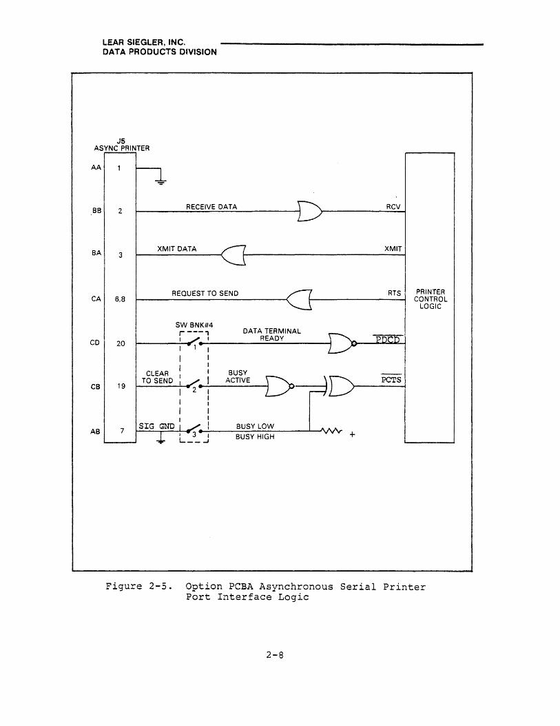
2.7.2 ASYNCHRONOUS PRINTER Port Interface
The ASYNCHRONOUS PRINTER interface is used to connect the ADM-42 directly to an asynchronous serial printer. Figure 2-5 shows the option PCBA logic associated with this interface.
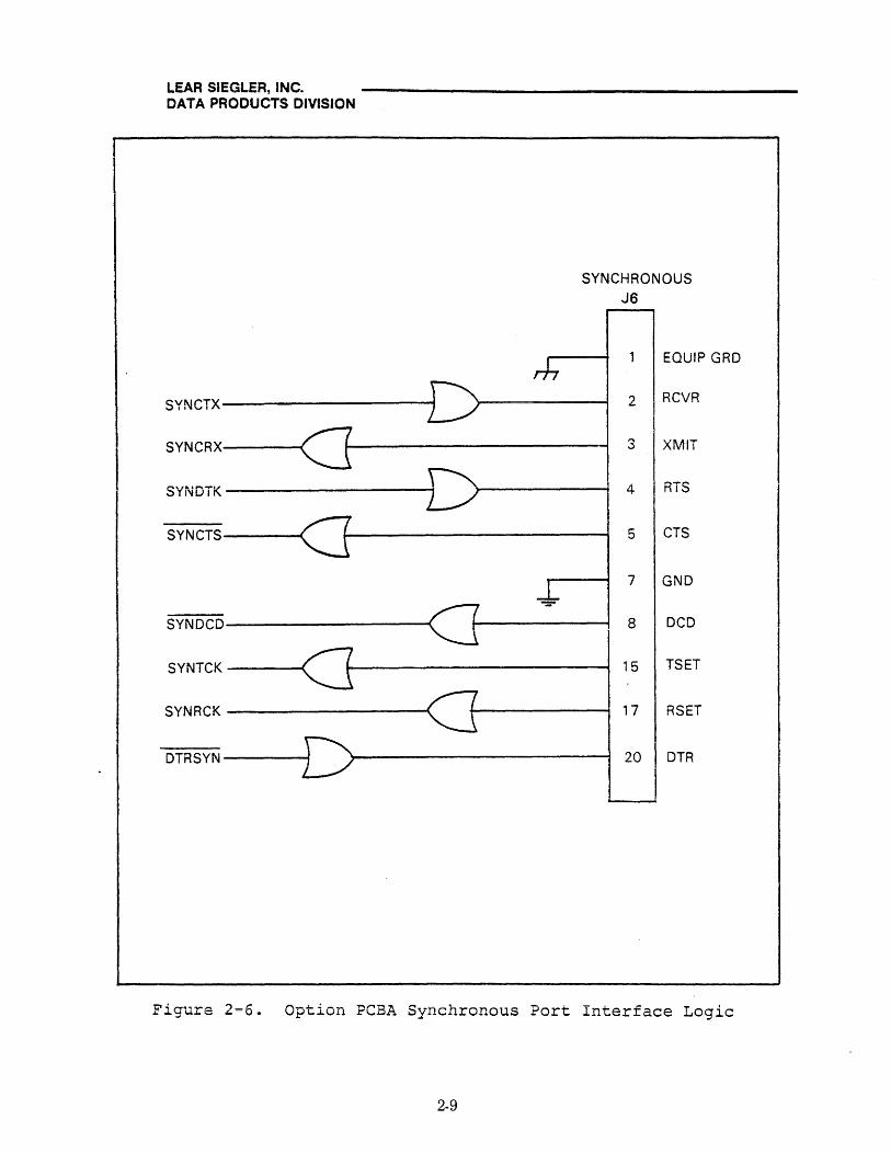
2.7.3 SYNCHRONOUS Port Interface
The SYNCHRONOUS interface is used to connect the ADM-42 directly to a synchronous device such as a Bell System Data Set. Figure 2-6 shows the option PCBA logic associated with this interface.
2-3

LEAR SIEGLER, INC. DATA PRODUCTS DIVISION
, ,--- ADM-4.2~ RS·232C MODEM
INTERFACE
,---CURRENT lOOP OPTION ~
XMTR
RCVR
r-- r--+ +
FULL 20 MA RCVR DUPl SOURCE
- - ~ DUPl I
FUU) HAlf FULL), HAlf I
DUPl T DUPl DUPt T DUPt I I
+ t W-~ • 20 MA XMTR SOURCE - -- '--
\ COMPUTER OR MODEM RS·232C PRINTER/SYNCHRONOUS
INTERFACE
f ~ -
~ TX } PRINTER
RX 1'-1 ~ SYNCHRONOUS "'--
RS·232C EXTENSION II a Ii is !i - DEVICE INTERFACE et
r-
MOOE~I-___ ...JP
I...- TX
}l DAISY CHAI" DEVICES
RX EXTENSION
ETC, "--
___ -----------8US EXTENSION-------------'\
STANDARD PCBA
BUFFERS
CABLE
, OPTION PCBA
BUFFERS
+-1-------1
Figure 2-1. Typical ADM-42 Interfaces
2-4
REMOTE CPU
I
LEAR SIEGLER, INC. DATA PRODUCTS DIVISION
J4 MODEM
J5 EXTENSION
AAW BA 2 ~ rl B~~K m_ 1 EQUIP GND (AA)
<==J~~~===---~======~--------~<==I ~ 2 IRTX (CA)
OUTPUT (+) 3W SCF 12~~~--~---4
14C RTN(-)
CLOUT 13r--t~S~EC~O~N~D~A~RY~----~-t~-==: __ ~=t----~--------1
CARRIER ~Er.3Tw~EpCT "" ....... --------11 Isc
SCA 19
CLIN *10
CLIN +'1
aa 3
CA 4
CB 5
CF 8
CC 6
AB
CD
~}- SCF KEYBOARD ~A 2 14C L/ I FUNCTIONS I
SECONDARY READY TO SEND
OUTPUT (+)
RTN H
RCVE DATA
REQUEST TO SEND
CLEAR TO SEND
CARRIER DETECT
DATA TERMINAL READY
'CURRENT LOOP CONNECTIONS ONLY
3 XMIT (BA)
4 RTS (CA)
5 CTS (CB)
8 DCD (CF)
6 DSR (CCl
7 SIG GND (AB)
Figure 2-2. ADM-42 Standard PCBA Interface Logic
2-5

LEAR SIEGLER, INC. DATA PRODUCTS DIVISION
R=100 OHMS
r- OPTION PCBA ~
J7 J3
£STOPCBA
J3 r-- - CABLE -
05
1 , .. " 2_
R I I I I
3 T 49 I
49
4 -----.oj r-- SO I SO -R I I
5 47 I
47
6-- ~ 48 I 48 -R I I 7 ' ... 45 45
81---- ~ 48 1 I 48 ~ R I I 9 43 43
101--- ~ 44 I I 44 ~
11 Rc ..
41 I I 41
121--- f-- 42 I I 42 ~
R I I 13 39
I 39
14~ ~ 40 I 40 ~ R I I
15 35 35
16'_ I I I ~ 38 38 ~
R I I 17 31 31
111_. ~ 32 I I 32 --R I I 19 25 2S
20- .--- 26 I I 26 ---
21 ~ .. 21 I I 21
22- .--- 22 I I 22 --
23 R ..
17 I I 17
24_ ~ 18 I I 18 --~ .. I I I 13 25. 13
28_~ ~ 14 I I 14 ~
27 R ..
9 I I 9
28~ ~ 10 I I 10 I--R I I 29 5
I I 5
301--- ~ .. t- 6 I I
6~
31 I 1 1
32~ t-~ I I
~~ R ... ~ J2 J2::: ~ 33 21 ,
341---~ .. ~ 22
I 22~
35 .... 37 37 I
361---R .... ~ 38 38 1---4
:H 33 I 33 I
R ~ 34 I'
34 1---4
39 29 29
03
DO
02
01
07
06
A12
A15
A8
A9
AO
A2
A4
A6
MEMADY
REFGNT
BDCLK2
40~ ~ 30 I 30 f---4 R .. I i
41 ... 25 25 42 ____
~ 26 f 26 1---4
43 ! I 44 - I
VMA
MEMCLK
45 I 46 -----.oj I I
R I I 47 13 I I
13
48 - ~ 14 14 ~
49 R •
9 I I 9 ,. ... I I 50 !----4 ~ 10 10 ~
L-.-I I I....-"-- ~ _/
-"- .J.. .L..
DMAA/W
TSC
CABLE
r-0PTION PCBA ~
J8 J2 ~ R -
1
2~ R r--
04 3
... .Ic 37 4_ ~ 38
5
6 ""'"-- A 7 29
A14 81---- R ~ 30
9 c.&. 27 A13
10~ ....-- 28 R
11 ......... 23 Al0
12~ R
....-- 24
13 19 A11
141---- R ~ 20
15 15 Al
161----R ~
16
17 11 ... A3 18 ____
R ~ 12
19 7
201--- ~ R 8 AS
21 ..... 3
221--- ~ 4 A7
23 '--241--- ,........,..J3
R 25 .. I
41
261---- t- 42 R 27 39
281--- H40 .~ I I
35 29
2XCLK
30~ H36 R
02
31 y , 31
I 321--- R ~
32 R/W
33 27
34~ ~ 28
35
38~ R 37 ... 19
BA 381--- .--- 20
39
I--- i 40 ... R,. .. l
41 11 I
42 ~ ~ 12 R
43 7
44 ~ -- 8 I R
45 ....... 5
46 ~ R ~ 6
47 ...... 3 . 48 ---- R
~ 4
49 1
50 1-----4 ~ 2
I..-- 1..--1...
.~ .....
STOPCBA~
).J3 CABLE -r'\ I I
I I 37 I I 38 ~ I I I I I I 29 I I
30 f---i I I 27 I I 28 ~ I I 23 I I 24 ~ I I 19 I I 20 ~ I I 15 I I 16 ~ I I 11 I I 12 ~ I I
7 I I
~ 8 I I
3 I I \. ... I 4 1---4
J2 ;::: (-, 41
I I 42 ~ f I
I 39
I 40 ~ I I 35 I I 38 ~ I I 31 I I 32 ......... I I 27 I I 28 ~
I I I I I I 19 I I 20 1---4 I I I I I I 11 f I 12 ~ I I I I
7
8 ~ I I I I
5
I I 6 ~
3 I I 4 ~ I I 1 I I
2~ I I I..--\_)
-1,00 CABLE
Figure 2-3. Option PCBA CPU Bus Extension Interface Connector/Pin List
2-6

· LEAR SIEGLER, INC. DATA PRODUCTS DIVISION
PARALLEL PRINTER
J4
CB2 DATA STROBE
PBO 2 DATA i
PB1 3 DATA 2
PB2 4 DATA 3
PB3 5 DATA 4
PB4 6 DATA 5
PB5 7 DATA 6
, PB6 0 '"'".,.." .., 0 u ..... , ..... I
+5 9 DATA 8 PRINTER CBl LOGIC 10 ACK
PA6 11 BUSY
PA4 12 PAPER OUT
PA7 13 ON LINE
17 EQUIP GRD
16
}GRD 19
thru 30
PAO 31 RESET
PA5 32 NO FAULT
Figure 2=4. Opt~on PCBA Parallel Printer Port Interface Logic
2-7
LEAR SIEGLER, INC. DATA PRODUCTS DIVISION
J5 ASYNC PRINTER
AA
BB 2 RECEIVE DATA
XMIT DATA BA 3
REQUEST TO SEND CA 6.8
SW BNK#4 r---' DATA TERMINAL
CD I READY 20
I
I
CLEAR I
BUSY TO SEND ACTIVE D CB 19 2-
AS 7 SIG BUSY LOW
BUSY HIGH
RCV
XMIT
RTS PRINTER CONTROL
LOGIC
PCTS
+
Figure 2-5. Option PCBA Asynchronous Serial Printer Port Interface Logic
2-8
LEAR SIEGLER, INC. DATA PRODUCTS DIVISION
SYNCTX
SYNCRX (] SYNDTK
SYNCTS
-SYNDCD
SYNTCK
SYNRCK
DTRSYN
SYNCHRONOUS J6
EQUIP GRD
2 RCVR
3 XMIT
4 I RTS
5 CTS
7 GND
8 DCD
15 TSET
17 RSET
20 DTR
Figure 2=6. Option PCBA Synchronous Port Interface Logic
2-9

LEAR SIEGLER, INC. DATA PRODUCTS DIVISION
2.8 INSTALLING THE ADM-42
To install the ADM-42, proceed as follows:
~ Be sure the bubbZe packing has been removed fram the interior of the eZectronics unit. Damage to the equipment may resuZt if not removed.
1. Connect the data interface cable to the terminal using the appropriate interface information.
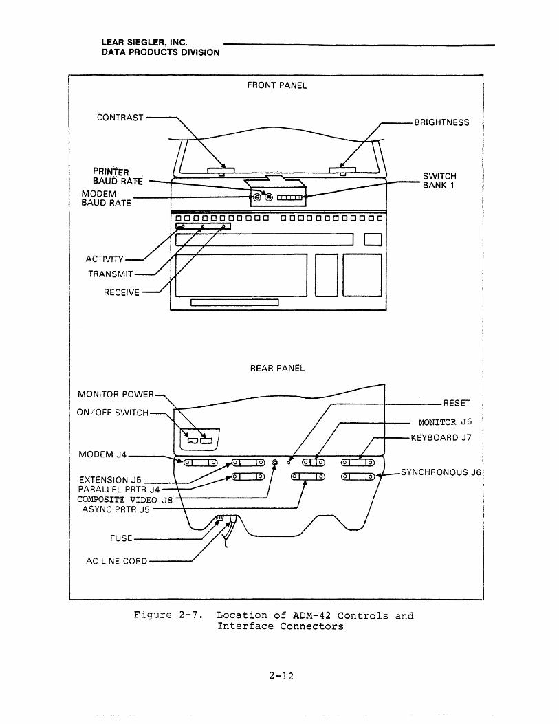
2. Check the ON/OFF switch to ensure it is in the OFF position. Refer to figure 2-7 and table 2-1 for rear panel control information.
3. Plug the terminal into a grounded AC outlet of the proper voltage.
4. Set the appropriate BAUD RATE switch (refer to table 2-1) to the desired baud rate.
5. Set the configuration control switches (see Section 1 illustrations) to the positions required to control the desired terminal characteristics.
6. Proceed to turn on the terminal.
2.9 TURN-ON AND TURN-OFF PROCEDURES
Turn-on of the ADM-42 is accomplished by complying with the following steps:
1. Set the ON/OFF switch to the ON position.
2. Note that in approximately 20 seconds after power turn-on, the cursor appears at the HOME position, and the rest of the screen is clear.
3. If the cursor does not appear after the warm-up period, momentarily press the HOME key. If this fails to produce the cursor, it is possible that the BRIGHTNESS and/or the CONTRAST controls are rnisadjusted. If this condition exists, slide the CONTRAST control until the background is barely visible. The cursor should be present.
2-10

LEAR SIEGLER, INC. DATA PRODUCTS DIVISION
4. If cursor still does not appear, press the CONV MODE key and verify that the key lights up. If so, troubleshoot the CRT monitor; if not, troubleshoot the terminal electronics.
Note
If data is not entered into video from the keyboard or remote device within approximately l5 minutes after terminal turn-on3 video will shut down~ Restore video by entering any character into video.
Turn-off of the ADM-42 is accomplished as follows:
If the terminal contains information that must be retained, be sure to transmit this information immediately to the remote computer. This is necessary as the display memory is cleared when the AC power switch is set to ON. As an alternate measure, print the information prior to turning off the terminal.
Turn-off the ADM-42 by setting the AC power switch to OFF.
2-11
LEAR SIEGLER, INC. DATA PRODUCTS DIVISION
FRONT PANEL
CONTRAST --........
PRINTER BAUORA1E --~ ________ ~~ ____ ~
MODEM BAUD RATE
,.---BRIGHTNESS
SWITCH ~---BANK 1
00000000000 000000000000
ACTIVITY
MONITOR POWER
ON/OFF SWITCH
EXTENSION J5 __ ~~ PARALLEL PRTR J4 --\--~
REAR PANEL
COMPOSITE VIDEO J8 -+-------~ ASYNCPRTRJ5----~--------------
FUSE ---------'
AC LINE CORD----
o
DO
__ ------~--------RESET
MONITOR J6
,--i---KEYBOARD J7
~-,~~-SYNCHRONOUSJ6
Figure 2-7. Location of ADM-42 Controls and Interface Connectors
2-12

LEAR SIEGLER, INC. DATA PRODUCTS DIVISION
Table 2-1. ADM-42 Controls and Interface Connectors
NAME OPERATIONAL DESCRIPTION
CONTRAST Control
BRIGHTNESS Control
SWITCH BANK 1 (Location 15M)
RECEIVE Indicator
TRANSMIT Indicator
ACTIVITY Indicator
PRINTER BAUD RATE and MODEM BAUD RATE Switches
FRONT PANEL
Slide potentiometer controls the character brightness relative to the background. Contrast is usually adjusted after brightness is established.
Slide potentiometer controls the overall brightness of the CRT display. Brightness is usually adjusted so that the display raster (background) is barely visible or just below the point of visibility.
Bank of eight two-position switches controls ADM-42 characteristics as follows:
SW 1 BREAK Key Enable/Disable
SW 2 Refresh Rate = 50/60 Hz
SW 3,4,5 Word Format
SW 6 Not Used
SW 7 Send Print Pseudo/Nonnal
SW 8 Full/Half Duplex
Lights when terminal is receiving data.
Lights when terminal is transmitting data.
Lights when keyboard is active.
16-position rotary switches control MODEM Port and PRINTER Port baud rates, as follows:
POSe RATE POSe RATE
0 50 8 1,800 1 75 9 2,000 2 110 10 2,400 3 134.5 11 3,600 4 150 12 4,800 5 300 13 7,200 6 600 14 9;600 7 1,200 15 N/A
2-13
LEAR SIEGLER, INC. DATA PRODUCTS DIVISION
Table 2-1. ADM-42 Controls and Interface Connectors (cont'd)
NAME
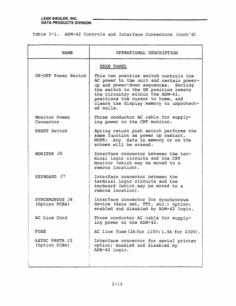
ON-OFF Power Switch
Monitor Power Connector
RESET Switch
MONITOR J6
KEYBOARD J7
SYNCHRONOUS J6 (Option PCBA)
AC Line Cord
FUSE
ASYNC PRNTR JS (Option PCBA)
OPERATIONAL DESCRIPTION
REAR PANEL
This two position switch controls the AC power to the unit and certain powerup and power-down sequences. Setting the switch to the ON position resets the circuitry within the ADM-42, positions the cursor to home, and clears the display memory to unprotected nulls.
Three conductor AC cable for supplying power to the CRT monitor.
Spring return push switch performs the same function as power up restart. NOTE: Any data in memory or on the screen will be erasede
Interface connector between the terminal logic circuits and the CRT monitor (which may be moved to a remote location).
Interface connector between the terminal logic circuits and the keyboard (which may be moved to a remote location).
Interface connector for synchronous device (data set, TTY, etc.) option; enabled and disabled by ADM-42 logic.
Three conductor AC cable for supplying power to the ADM-42.
AC line fuse (3A for llSVi 1. SA for 230V).
Interface connector for serial printer option; enabled and disabled by ADM-42 logic.
2-14
LEAR SIEGLER, INC. DATA PRODUCTS DIVISION
Table 2-1. ADM-42 Controls and Interface Connectors (cont'd)
NAME
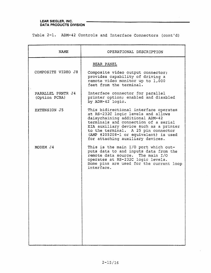
COMPOSITE VIDEO J8
PARALLEL PRNTR J4 (Option PCBA)
EXTENSION J5
MODEM J4
OPERATIONAL DESCRIPTION
REAR PANEL
Composite video output connector; provides capability of driving a remote video monitor up to 1,000 feet from the terminal.
Interface connector for parallel printer option; enabled and disabled by ADM-42 logic.
This bidirectional interface operates at RS-232C logic levels and allows daisychaining additional ADM-42 terminals and connection of a serial EIA auxiliary device such as a printer to the terminal. A 25 pin connector (AMP #205208-1 or equivalent) is used for attaching auxiliary devices.
This is the main I/O port which outputs data to and inputs data from the remote data source. The main I/O operates at RS-232C logic levels. Some pins are used for the current loop interface.
2-15/16


LEAR SIEGLER, INC. DATA PRODUCTS DIVISION
SECTION 3
OPERATING INSTRUCTIONS
3.1 INTRODUCTION
The purpose of this section is to describe how to use the ADM-42 Data Display Terminal. The terminal is used to enter, display, and send information to a remote computer or modem, printer, terminal or other auxiliary device, and to receive and display information from the computer or modem.
3.2 KEYBOARD FUNCTIONS
The operator uses a keyboard that resembles the keyboard of a conventional typewriter to enter data. Information typed by the operator may be displayed on a cathode ray tube (CRT) immediately, as during full-duplex operation. Allor part of the display can be changed by the operator (text editing), or from the remote computer. This allows updating of information and quick, clean corrections of typing errors.
Figure 3-1 shows the keyboard layout of a standard ADM-42 Data Display Terminal. Many of the keys control several operations, depending on how they are used in combination with other keys on the terminal. Table 3-1, in conjunction with the paragraphs which follow, list and describe in detail operator keyboard operations. Those special operations beyond those associated with conventional typewriter key operations are described in detail under Programming Considerations in this section.
Except for a number of special operation keys, the keyboard is equipped with key roll-over protection (i.e., each key which is pressed must be released before the next key code can be produced) .
The keyboard contains the following functional keys:
• Terminal control keys
• Lower and upper case alpha characters
3-1

t-xj ...... -lQ ~ I-( CD
W I
/-'
P t1 !3:: I
.c::.. (\.)
t1 III rt III
t1 ...... -[/}
'Ll w P I III
(\.) "<!
t-3 CD I-( ;3 ...... -~ III /-'
Ul rt III ~ P. III Ii P.
~ CD
"<! tJ' 0 III I-( P.
--------_.---------------------------------------------------------------------------------------------------------------,
1 r F2 Fl
o CONY 22 r3 MODE
40
60
CTRL
80
o
100
r F3
4 r F4
24 PAGE PROG EDIT MODE
r 1
r F5 F6 F1 F8
r
5 26 r CLEAR CLEAR SPACE NULL
SPACE BAR
r F9
10 11 12
FlO FIt f12
28 29 30 PROT WRITE CHAR CHAR MODE PROT INSERT DELETE
13
f13
31 LINE
INSERT
14 15
F14 F15
32 -- 33 LINE
DELETE LINE
ERASE
112 NEW LINE
16 11 18 19 20 21
f16 BREAK SOM ESC SEND PRINT MSG
34 35 36 31 38 39 PAGE RESET EOM RUB
ERASE cMD SEND SEND LINE PAGE
54 55 56 51 58 59 PAGE PAGE FWD BACK 7 8 9 -
14 15 TAB
HOME SET CLEAR
16 11 18 19
4 5 6 TAB
94 95 96 97 98 99 - - 1 2 3 R E T
113 114 115 116 117 U
t • 0 R , N
or J>m -Il> ):loll .,,(1) lln; OQ cr em o}' -1-(l)Z cP <: iii (5 Z

LEAR SIEGLER, INC. DATA PRODUCTS DIVISION
• Numeric characters on main and auxiliary keyboards
• Numeric characters with SHIFT (main keyboard only)
• Special characters
• Special characters with SHIFT
• Operational control keys
• Operational control keys with SHIFT
• Function keys FI through Fl6
• Function keys FI through Fl6 with SHIFT
3.2.1 Terminal Control Keys
The SHIFT key is similar to the shift key of a conventional typewriter (refer to table 3-1, item 7). The key is used to produce shifted ASCII codes associated with upper case alpha characters (A to Z) and with the upper symbols of keys capable of producing two different symbols. No character is produced when the SHIFT key is operated. When used in conjunction with special operation keys (ESC, CLEAR SPACE, etc.) the SHIFT key causes shifted ASCII codes to be produced, thus giving rise to alternate functions.
The RESET keys reset a keyboard LOCK condition. In a polling environment, the operation returns the terminal to nonpolling operation. When RESET is pressed while CTRL is depressed, a firmware RESET is performed which clears all dynamic modes and protected fields.
Note
The RESET switch at the rear of the ter.mir~l causes a hardware RESET~ as well as a firmware reset.
The CAP LOCK key allows the operator to type a series of shifted alpha characters (but not shifted numeric or special characters) continuously, without using the SHIFT key. Pressing the CAP LOCK key sets the CAP function and lights a lamp in the key. Pressing CAP LOCK a second time releases the function and extinguishes the lamp. No character is produced when CAP LOCK is pressed.
The space bar produces an ASCII space code to be produced and stored in memory for transmission. A space character (blank) also appears on the CRT display.
3-3

LEAR SIEGLER, INC. DATA PRODUCTS DIVISION
Table 3-1. Keyboard Operations
CONTROL
1. Alphabet Keys
2. Alphabet, with SHIFT
3. Numeric (Main and Numeric Keyboards)
4. Numeric (Main Keyboard) with SHIFT
5. Special Character (Main and Numeric Keyboards)
6. Special Character (Main Keyboard) With SHIFT
7. Terminal Control:
CAP LOCK
SHIFT
RESET
CTRL/SHIFT/RESET
SPACE BAR
8. Cursor Control:
TAB SHIFT/BACKTAB
HOME
TAB SET/CLEAR
PAR. REF.
3.2.2
3.2.2
3.2.2
3.2.2
3.2.3
3.2.3
3.2.2
3.3
3-4
FUNCTION
Lower case a to z
Upper case A to Z
Numerals 0 to 9
Special Characters
Special Characters
Special Characters
Locks/unlocks keyboard CAP status
Lower/upper case alpha characters; special characters and operations
Clear frame or parity errors on status Line 25.
Firmware Reset
ASCII space code in memory; space character on CRT screen
Slew cursor to next tab forward/backward (Protect Mode or Typewriter Tab Mode)
Cursor to HOME position
Set (shifted) tabs
LEAR SIEGLER, INC. DATA PRODUCTS DIVISION
Table 3-1. Keyboard Operations (cont'd)
CONTROL PAR. REF.
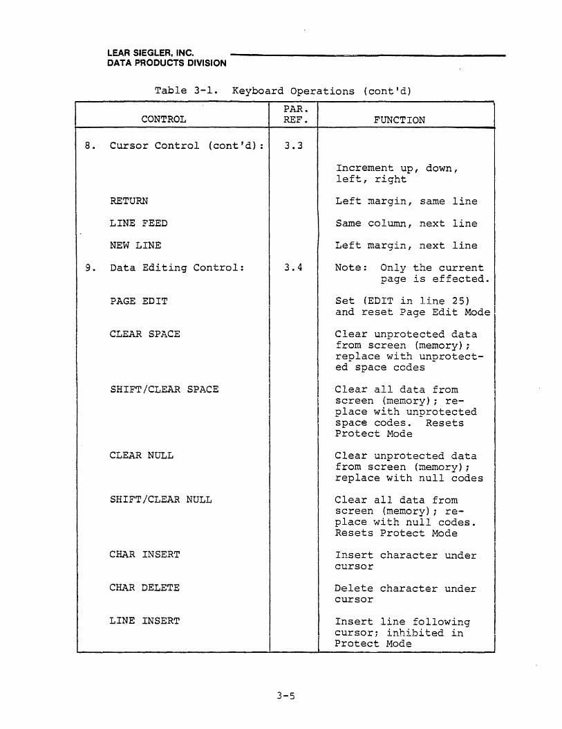
8. Cursor Control (cont'd): 3.3
RETURN
LINE FEED
NEW LINE
9. Data Editing Control: 3.4
PAGE EDIT
CLEAR SPACE
SHIFT/CLEAR SPACE
CLEAR NULL
SHIFT/CLEAR NULL
CHAR INSERT
CHAR DELETE
LINE INSERT
3-5
FUNCTION
Increment up, down, left, right
Left margin, same line
Same column, next line
Left margin, next line
Note: Only the current page is effected.
Set (EDIT in line 25) and reset Page Edit Mode
Clear unprotected data from screen (memory); replace with unprotected space codes
Clear all data from screen (memory); replace with unprotected space codes. Resets Protect Mode
Clear unprotected data from screen (memory); replace with null codes
Clear all data from screen (memory); replace with null codes. Resets Protect Mode
Insert character under cursor
Delete character under cursor
Insert line following cursor, inhibited in Protect Mode

LEAR SIEGLER, INC. DATA PRODUCTS DIVISION
Table 3-1. Keyboard Operations (cont'd)
CONTROL PAR. REF.
9. Data Editing Control 3.4 (cant I d) :
LINE DELETE
LINE ERASE
SHIFT/LINE ERASE
PAGE ERASE
SHIFT/PAGE ERASE
PAGE FWD
PAGE BACK
SHIFT/PAGE BACK
10. Data Transmission Control:
CONV MODE
PROG MODE
PROT MODE
3.5
3-6
FUNCTION
Delete line containing cursor; inhibited in Protect Mode
Erase line from cursor to end of line; replace with spaces
Erase line from cursor to end of line; replace with nulls
Erase unprotected characters on page, starting with cursor; replace with spaces
Erase unprotected characters on page, starting with cursor; replace with nulls
Shift display (memory) one page forward
Shift display (memory) one page backwards
Sets AUTO PAGE Mode
Set (lit) Conversation Mode and reset (unlit) to Block Mode
Set (PROG in Line 25) and reset Program Mode
Set (PROT in Line 25) and reset Protect Mode

LEAR SIEGLER, INC. DATA PRODUCTS DIVISION
Table 3-1. Keyboard Operations (cont'd)
CONTROL
10. Data Transmission Control (cont'd):
WRITE PROT
BREAK
SaM
EOM
SEND MSG
SHIFT/SEND MSG
SHIFT/PRINT
SEND LINE
SHIFT SEND LINE
SEND PAGE
SHIFT/SEND PAGE
PAR. REF.
3.5
3-7
FUNCTION
Set (WPRT in Line 25) and reset Write Protect Mode
Send BREAK code to computer
Cause start of message (STX) code to be formatted on screen
Cause end of message (ETXj code to be formatted on scre.en
Cause all unprotected data bracketed by SOM-EOM codes to be transmitted
Cause all data brack6t= ed by SOM-EOM codes to be transmitted
Send display data to printer in Print Form Format (PRNT in Line 25)
Send displayed data to printer in Free Format (PRNT in Line 25)
Send foreground data from beginning of line to cursor
Send all data from beginning of line to cursor
Send foreground data on page thru cursor position
Send all data on page thru cursor position

LEAR SIEGLER, INC. DATA PRODUCTS DIVISION
3.2.2 Alphanumeric Keys
The alphanumeric keys (refer to table 3-1, items I, 2, and 3) are used to write any of the standard ASCII characters shown in ascending ASCII sequence in figure 1-3. Pressing any alpha (A to Z) or numberic (0 to 9) key produces the ASCII 7-bit binary code associated with the unshifted character. When used in conjunction with the SHIFT key, the ASCII code is shifted to that associated with the upper case character on an alpha (A to Z) key and the upper symbol on a double-operation key. Such keys include main keyboard numeric keys (which are double-operation keys) but not auxiliary keyboard keys (0 to 9 and special characters TAB-,.). The auxiliary (numeric) key pad is mainly for convenience when performing a large number of numeric entries. The arrangement of these keys facilitates making the numeric entries, as opposed to using the main keyboard keys.
Only alpha key-operations are shifted by means of the CAP LOCK key. Numeric key operations (on main and auxiliary keyboards) , as well as all special character key operations are not functionally affected by the CAP LOCK key. Typically, the ASCII code produced by an alpha numberic key closure represents simply the character typed. Thus, a typed y, Y, or 7 represents a y, Y, or 7. When used in conjunction with a CTRL or ESC key, however, the resulting ASCII code has an entirely different significance, depending upon which special operation has been selected. These special operations are described under Programming Considerations.
3.2.3 Special Character Keys
Functionally similar to the alphanumeric keys, the special character keys (shifted and unshifted) when used in the fashion of a conventional typewriter, produce ASCII codes which express the symbol on the key (refer to table 3-1, items 5 and 6). Also as for alphanumeric key operations, a CTRL, ESC, or special function code preceding the special character causes the resulting ASCII code to have special programming significance, as described under Programming Considerations.
3.2.4 Operational Control Keys
In addition to the terminal control keys described in paragraph 3.2.1, the keyboard contains a number of operational control keys which are used unshifted or shifted to provide specific machine operations. These keys consist of those keys not previously categorized as alphan~eric and special character keys (items 1 thru 6, table 3-1) with the exception of the ESC, CTRL, and Fl thru F16 keys. For the purpose of this discussion, the operational control keys have been grouped according to specific operations, each of which is discussed in detail in the paragraphs, which follow.
3-8

LEAR SIEGLER, INC. DATA PRODUCTS DIVISION
3.3 CURSOR CONTROL OPERATIONS
The cursor is a bright rectangular marker on the ADM-42 screen that indicates the entry point for the next character to be displayed. As characters are entered, the cursor moves from left to right across the display. When the cursor is positioned over a character already displayed, that character appears as a reverse image in the cursor. Cursor positioning may be controlled from the keyboard or from the remote computer. Operational control of the cursor is accomplished by using appropriately labeled operational control keys (unshifted or shifted) on the keyboard.
The following operational control keys control cursor position. In each instance, if the selected position is protected, the cursor moves along that line and to following lines, if necessary, to the first unprotected position.
• HOME
• t
• +
· .. · .....
• NEW LINE
• SHIFT/TAB SET
Moves the cursor to the first character position on the current page (top line, most left-hand position), or to the first unprotected position.
"Down Line" moves cursor to the same column or next unprotected position of the next lower line. Scrolling will take place unless AUTO PAGE or Protect Mode is set.
"Up Line" moves cursor to the same column or next unprotected position of the next higher line. When the top line is reached, cursor wraps around to the bottom line of the same page.
"Back Space" moves cursor one position to the left, or to the last unprotected position in the next preceding line.
"Fore Space" moves cursor one position to the right, or to the first unprotected position in the next following line.
Causes cursor to move to the first unprotected position in the next lower line. Scrolling will take place unless AUTO PAGE or Protect Mode is set.
Writes vertical column of protected spaces at cursor position, starting with line containing cursor. Protect Mode is automatically set.
3-9
LEAR SIEGLER, INC. DATA PRODUCTS DIVISION
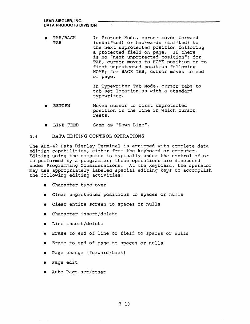
• TAB/BACK TAB
• RETURN
• LINE FEED
In Protect Mode, cursor moves forward (unshifted) or backwards (shifted) to the next unprotected position following a protected field on pagee If there is no "next unprotected position": for TAB, cursor moves to HOME position or to first unprotected position following HOME; for BACK TAB, cursor moves to end of page.
In Typewriter Tab Mode, cursor tabs to tab set location as with a standard typewriter.
Moves cursor to first unprotected position in the line in which cursor rests.
Same as "Down Line".
3.4 DATA EDITING CONTROL OPERATIONS
The ADM-42 Data Display Ter.minal is equipped with complete data editing capabilities, either from the keyboard or computer. Editing using the computer is typically under the control of or is pe"rformed by a progranuner; these operations are discussed under Programming Considerations. At the keyboard, the operator may use appropriately labeled special editing keys to accomplish the following editing activities:
• Character type-over
• Clear unprotected positions to spaces or nulls
• Clear entire screen to spaces or nulls
• Character insert/delete
• Line insert/delete
• Erase to end of line or field to spaces or nulls
• Erase to end of page to spaces or nulls
• Page change ( forward/back)
• Page edit
• Auto Page set/reset
3-10

LEAR SIEGLER, INC. DATA PRODUCTS DIVISION
The following keys are used for data editing at the keyboard:
• PAGE EDIT, when pressed once establishes Page Edit Mode; "EDIT" is displayed in status line 25. When pressed again, it terminates Page Edit Mode; modifies movement of data for CHAR INSERT and CHAR DELETE operations when doing text editing.
• CLEAR SPACE (unshifted) clears all unprotected data from the screen and from memory, to space codes. When used with SHIFT, the key resets Protect Mode and clears all data from the screen and from memory, to space codes. These codes remain in memory until overwritten by other codes.
• CLEAR NULL (unshifted) clears all unprotected data from the screen and from memory, to null codes. When used with SHIFT, the key resets Protect Mode and clears all data from the screen and from memory, to null codes. These codes remain in memory until overwritten by other codes.
• CHAR INSERT may operate in combination with PAGE EDIT. When not operating in Page Edit Mode, the key moves character under cursor and all following characters one position to the right. If no protected field is encountered on the line, the operation terminates at the end of the line, and the last character on the line is lost (if the line is full). A space character is written under the cursor.
When operating in Page Edit Mode, CHAR INSERT writes a space under the cursor and moves all following characters one position to the right and onto the following line when the line containing the cursor is full. Shifting stops when a protected field is encountered.
• CHAR DELETE operates in combination with PAGE EDIT. When not operating in Page Edit Mode, the key deletes character under the cursor. All characters that follow in the field or line move one position to the left and fill the space left by the deletion. A space or personality code is written in the last position of the field or line.
When operating in Page Edit Mode, CHAR DELETE deletes character under the cursor. All unprotected characters between the cursor and the first protected field on the page shift one space to the left. A space or personality code is written in the last position of the field or line.
3-11

LEAR SIEGLER, INC. DATA PRODUCTS DIVISION
• LINE INSERT. Depressing the LINE INSERT key causes the entire line where the cursor is located and all lower lines, to shift downwards one line. This creates an empty line of unprotected spaces or personality code on which additional characters may be entered. If the entire page is filled when creating this new line, the bottom line is lost. The cursor moves to the first unprotected position of the new blank line. If in write Protect Mode, LINE INSERT resets that mode. If in Protect Mode, operation is not performed.
• LINE DELETE. Depressing the LINE DELETE key causes the entire line on which the cursor is located to be erased. Simultaneously, all lower lines shift upwards one line. The cursor moves to the first character position of the first line (that moves upwards). The bottom line is filled with unprotected spaces or personality codes. If in Protect Mode, operation is not performed.
• LINE ERASE erases all characters, beginning with the cursor position, through the end of the line field that contains the cursor. Erased characters are replaced with space (unshifted) or null codes (shifted). If operating in the Write Protect Mode, space or null codes are written protected.
• PAGE ERASE erases all unprotected characters, starting at the cursor position and progressing through to the end of the data on display. Erased characters are replaced with space codes (unshifted) or null codes (shifted). If operating in the Write Protect Mode, pressing the PAGE ERASE key resets the Write Protect Mode.
• PAGE FWD shifts the display and the memory one page forward. When page 8 is reached, the shift is to page 1.
• PAGE BACK shifts the display and the memory one page backwards. When used with SHIFT, PAGE BACK sets AUTO PAGE Mode.
3-12

LEAR SIEGLER, INC. DATA PRODUCTS DIVISION
3.4.1 Editing Examples
In some installations, depending on the manner in which the ADM-42 is used, editing is an important consideration. Operators wishing to gain full use of the instrument's editing capabilities must become familiar with the operation of the keys listed above.
The following examples provide practice in the use of the editing keys:
Note
It should not be construed from these examples that the method presented is the only method of making the required editorial chAnges. Other steps can be taken that produce the same end result.
Table 3-2 is an example of formatted (protected and unprotected) data entry errors (unedited response) that are easily corrected, before sending the data to the remote computer. (The lines are numbered for illustrative purposes only, to refer to them in explaining how corrections are made.)
The operator reviews the data on display and corrects errors as follows:
Line 1. Press the HOME key. Cursor moves to the liD" position. Type R, and note that R replaces the D.
Note
If cursor does not move to the ,~" position when the HOME key is pressed~ the terminal is probably not operating in the Protect Mode. To plaoe the terminal in the Proteot Mode~ press PROT MODE key.
Line 2. Press the LINE FEED key. Press the ~ key as necessary to place the cursor over the 8. Press the CHAR INSERT key, and note that everything on this line to the right of the cursor moves one space to the right. Type 8 to correct the error.
Line 4. Press the TAB key twice to move the cursor over the $ symbol. Press the CHAR DELETE key, and note that $ is erased and all characters on this line shift left one space to correct the error.
3-13

LEAR SIEGLER, INC. DATA PRODUCTS DIVISION
Table 3-2. Editing Example
QUERY CORRECT RESPONSE UNEDITED RESPONSE
1. Description: Reclining Chair Declining Chair
2. Stock No.: RCB01887-04L RCB0187-04L
3. Quantity: 1 1
4. Price: 369.95 $369.95
5. Sales Tax: 22.20 22.19
6. Total Amount: 392.15 392.14
7. Clerk No. : 23 23
Line 5. Press the NEW LINE key, and note that cursor moves over the first "2" on line 5. Press the ... key to move the cursor over the "1". Type 20 to correct this entry.
Line 6. Press the • key, and note that cursor moves straight down to line 6. Press the ..... key as necessary to move the cursor over the 4. Type 5 to correct the error.
In the following example, the first paragraph shows a partial page as it should have been prepared. The lines are numbered for purposes of illustration only, to simplify referencing to specific lines in subsequent paragraphs that show how the copy was actually prepared (second paragraph), and how the copy was corrected.
Corrected Copy
1. Some of the basic decisions in the $4.8 billion sales, which 2. can be blocked by Congress, were taken months ago and were no 3. surprise to observers of u.S. Middle East policy. But 4. timing of the announcement, capping a week of mutual u.s. 5. Israel recriminations and a high visibility Egyptian diplo-6. matic offensive, almost seemed calculated to heat the atmos-
3-14
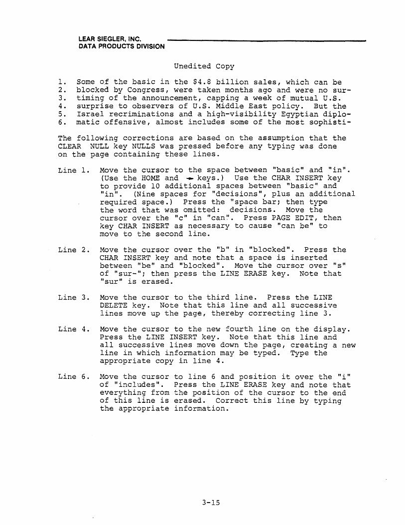
LEAR SIEGLER, INC. DATA PRODUCTS DIVISION
Unedited Copy
10 Some of the basic in the $4.8 billion sales, which can be 2. blocked by Congress, were taken months ago and were no sur-3. timing of the announcement, capping a week of mutual U.s. 4. surprise to observers of U.S. Middle East policy. But the 5. Israel recriminations and a high-visibility Egyptian diplo-6. matic offensive, almost includes some of the most sophisti-
The following corrections are based on the assumption that the CLEAR NULL key NULLS was pressed before any typing was done on the page containing these lines.
Line 1. Move the cursor to the space between "basic" and "in". (Use the HOME and ~ keys.) Use the CHAR INSERT key to provide 10 additional spaces between "basic" and "in". (Nine spaces for "decisions", plus an additional required space.) Press the "space bar; then type the word that was omitted: decisions. Move the cursor over the "e" in "can~'.. Press PAGE EDIT! then key CHAR INSERT as necessary to cause "can be" to move to the second line.
Line 2. Move the cursor over the "b" in "blocked". Press the CHAR INSERT key and note that a space is inserted between "be" and "blocked ll
• Move the cursor over "s" of "sur-"; then press the LINE ERASE key. Note that "sur" is erased.
Line 3. Move the cursor to the third line. Press the LINE DELETE key. Note that this line and all successive lines move up the page, thereby correcting line 3.
Line 4. Move the cursor to the new fourth line on the display.
Line 6.
Press the LINE INSERT key. Note that this line and all successive lines move down the page, creating a new line in which information may be typed. Type the appropriate copy in line 4.
Move the cursor of "includes". everything from of this line is the appropriate
to line 6 and position it over the "i" Press the LINE ERASE key and note that the position of the cursor to the end erased. Correct this line by typing information.
3-15

LEAR SIEGLER, INC. DATA PRODUCTS DIVISION
Note
An aZternate way of making corrections that involve making erasures~ suah as in line 6~ is simply to write over the unwanted material. Replaaing old material with new material is an automatia erasure.
3.5 DATA TRANSMISSION CONTROL OPERATIONS
Data which has been displayed on the CRT screen (and automatically stored in memory) may be transmitted to a remote computer. Modes of transmission include the Block Mode, Conversation Mode, Print Mode, Polling Mode, and ADM-l Mode. Conversation Mode may be selected by pressing CONV MODE and observing the key light up. Block Mode may be selected by pressing CONV MODE a second time and observing the light go out. Polling Mode operations require a series of actions which are described under Polling, paragraph 3.9.
3.5.1 Transmission (Baud) Rates
The ADM-42 operate"s with a variet.y of computers, and sometimes communicates wit~ the computer over telephone data lines. These conditions require different transmission (baud) rates from one installation to the next. Using the BAUD RATE switches located above the keyboard (see figure 1-5), it is possible to select a data transmission rate of 50, 75, 110, 134.5, 150, 300, 600, 1200, 1800, 2000, 2400, 3600, 4800, 7200, or 9600 depending upon the installation requirements. The baud rates set by these switches may be dynamically changed by an escape sequence, as described under Programming Considerations.
3.5.2 Block Mode Transmission
In the Block Mode, information is transmitted and received as complete messages or blocks of data (compared with character-bycharacter transmission in Conversation Mode). The operator enters the complete message. The characters are displayed and stored, but are not automatically transmitted. After the message has been completed, the operator can edit the information, then use a SEND MSG, SEND PAGE, or SEND LINE special operation key which causes all or part of the message to be transmitted. Refer to Programming Considerations for programmer-type information concerning the character codes associated with these operations.
Note
Personality changes will change and/or add to such Block Mode control codes as PS~ US~ and CR.
3-16

LEAR SIEGLER, INC. DATA PRODUCTS DIVISION
The following special-operation keys are used for Block Mode transmission:
• SEND LINE (unshifted) causes transmission of unprotected information starting at the beginning of the line in which the cursor is located and continuing through the original cursor position. Cursor stops at first cursor position, on next line, unless Protect Mode is set;
. then cursor returns to original position'" Protected data is bracketed by FS (personality) codes. If ADM-l Mode is set, FS codes are not transmitted. Pressing SEND LINE while pressing the SHIFT key causes all characters in the line containing the cursor (up to cursor position) to be transmitted, followed by a return code. Protected data is bracketed by "ESC)" and "ESC(". Scrolling will occur if SEND LINE is executed for bottom line.
• SEND PAGE (unshifted) causes transmission of unprotected characters in the displayed page, starting with the first unprotected character and continuing to the position the cursor was in when SEND PAGE was keyed, followed by a ~eturn code. Each protected field skipped is indicated by an FS (personality) code, and each line ter.minates in a US (personality) code. If ADM-l Mode is set, FS and US codes are not transmitted. Pressing SEND PAGE while pressing SHIFT causes all characters on the page (through cursor position) to be transmitted. The shifted SEND PAGE causes protected data to be bracketed by "ESC)" and "ESC(".
• SEND MSG (unshifted) causes transmission of unprotected characters on the displayed page which are bracketed by SOM-EOM codes. The cursor backspaces until an SOM (STX) code is found, then all unprotected characters are transmitted until an EOM (ETX) code is encountered; then a return code is transmitted. If no STX is encountered, transmission starts at HOME position; if no ETX is encountered, transmission ends at the end of page. Pressing SEND MSG while holding the SHIFT key causes all characters in the message to be transmitted. Each protected field is indicated by an FS code, unless ADM-l is set.
3.5.3 Example of Block Mode Transmission
In this Block Mode example, the ADM-42 is located at the cashier's stand in a furniture store. For each sale, the cashier fills out a form on the CRT screen. This action notifies the central computer of a change in inventory level and provides accurate inventory control~
3-17

LEAR SIEGLER, INC. DATA PRODUCTS DIVISION
1. The operator presses the appropriate Fl through F16 key. A three-character code (SOH/Char/CR) is produced which notifies the computer of a retail sale. (Code does not appear on the screen.)
2. The computer recognizes the code and responds with the following form in protected characters:
DESCRIPTION: STOCK NO.: QUANTITY: PRICE: SALES TAX: TOTAL AMOUNT: CLERK NO.:
3. The display is in the Protect Mode with the cursor in the space following DESCRIPTION. The cashier fills out the form. After each entry, she presses the TAB key, which positions the cursor to the, first unprotected space following the next protected field--in this case, the space after the next item on the form.
DESCRIPTION: STOCK NO.: QUANTITY: PRICE: SALES TAX: TOTAL AMOUNT: CLERK NO.:
SOFA BRN (TAB) 01552 (TAB) 1 (TAB) 249.95 (TAB) 12.50 (TAB) 262.45 (TAB) 25
4. After completing the last entry on the form, the cashier operates the SEND PAGE key, which transmits the unprotected data (the cashier's entries only) to the central computer, in the following format: FS SOFA BRN US FS 01552 US FS 249.95 US .... etc.
5. The computer then responds with an acknowledgement of message received, and clears the display.
3.5.4 Conversation Mode Transmission
In the Conversation Mode, information is transmitted character by character, as it is typed. The mode is typically used for interactive communication with the computer, where dialog with the computer is desired. Data will be transmitted either HALF DUPLEX or FULL DUPLEX, depending upon the setting of SW 8 of Switch Bank No. 1 (location 15M) within the terminal (see figure 1-5). During Conversation Mode transmission, execution of a command sequence either from the keyboard or the computer will cause the appropriate action at the terminal.
3-18

LEAR SIEGLER, INC. DATA PRODUCTS DIVISION
In the HALF DUPLEX mode of operation, information can be sent to or received from the computer, but in only one direction at a time. Characters are transmitted and displayed one character at a time, as they are typed. Received characters are displayed as they are received. In the FULL DUPLEX mode of operation, information can be transmitted and received simultaneously. Characters are transmitted one character at a time as they are typed, but are displayed on the CRT only when they have been echoed back from the computer. Received characters are displayed as they are received. Some keyboard operations are not tr~nsmittedi._ fo_r example: EOM, SaM, CTRL, SHIFT, CHAR INSERT,- PAGE EDIT, LIN-E--INSERT, PAGE ERASE I PRINT I SEND LINE, BACK TAB I e-tc.
3.5.5 Example of Conversation Mode Transmission
In this Conversation mode example, the remote computer is running a conversational program instructing the operator in the use of the BASIC programming language. The computer asks a multiplechoice question which requires an operator response.
Computer: Before we can have the computer work with data, we must have the data read in with a
Operator:
Computer:
Computer:
Operator:
Computer:
statement.
(1. Read 2. Print 3. Data 4. None of these)
1
Correct
All data that is read in using a read statement must appear in some statement.
- (1 .. - Input 2. Print 3. Data 4. None of these)
1·
Incorrect. The correct answer is 3. The input statement is similar to the read statement, but calls for the input to be made from the ADM-42 rather than from the data statements. Read and data go together .
........... And so on.
3-19

LEAR SIEGLER, INC. DATA PRODUCTS DIVISION
3.5.6 Serial Print Mode Transmission
Serial Print Mode transmission requires an asynchronous Serial Printer Interface installation as described in Section 2 of this manual. The interface can be used with RS-23-C compatible serial printers, including buffered printers, as well as character-by-character printerss With this interface, the information input from the computer is buffered to make it available for editing and additions from the terminal prior to printing. In addition, the printer can be operated at anyone of the transmission baud rates listed in paragraph 3.5.1. The Print Mode can be initiated from the keyboard using the PRINT key, or SHIFT/PRINT keys. The Print Mode can also be entered by means of escape sequence initiated from the keyboard or the remote computer. Using the PRINT key or the SHIFT/PRINT keys, data can be sent to the printer in one of two modes: page format and free form. An additional buffered Print Mode is available via an "ESC "sequence. Also, printing protected fields as spaces is available via an ESC @" sequence.
In either the page format or free form mode, data is transmitted continuously as long as the printer and the terminal are ready. These conditions are monitored to provide printer/terminal control in the following manner (see figure 2-5):
1. The serial printer interface is enabled by setting SW 8 of Switch Bank 4 (location 3L on option PCBA) to ON and SW 2 at switch location 4A to ON, thus enabling the CLEAR TO SEND line.
2. When the terminal is ready to transmit data, REQUEST TO SEND (RTS) is sent to the printer.
3. If the printer is ready, it signals not BUSY over the CLEAR TO SEND (CTS) line, which alerts the terminal. Depending upon which printer is selected, CTS (NOT BUSY) may be active when high or low. SW 2 and SW 3 at switch location 4A are provided to accommodate each style printer. SW 2 must be ON to allow external printer control. Then, if SW 3 is ON, BUSY (NOT READY) is active low; if OFF, BUSY (NOT READY) is active high.
3-20

LEAR SIEGLER, INC. DATA PRODUCTS DIVISION
Print Format Mode allows data to be printed exactly as displayed on the-CRT screen. Transmission is initiated by pressing the PRINT key at the desired print operation stopping position~ (Print Format Mode can also be entered via a keyboard-initiated or computer-initiated "ESC pIt sequence.) The following takes place:
1. "PRNT" is displayed in status line 25 and "EMil is written at the cursor position as a STOP code.
2. The cursor is moved to the HOME position.
3. The code sequence CR LF NULL is sent to the printer, followed by the data displayed on the screen.
4. NULL characters are sent as spaces and trailing nulls and spaces on a line are not sent. When the last character on each line is sent, the terminal sends the CR LF NULL sequence before moving to the next line.
5. Upon reaching the STOP code, the operation is terminated, a final CR LF NULL is sent, and the STOP code fEr-i) is overwritten with a space.
Note
A STOP code within the text will cause the printing to stop at that point.
6. Breaks in the transmission may occur to allow for mechanical printer operations or other delays, by means of the printer READY logic described above. If the printer goes BUSY upon receipt of a control character (CR, LF, etc.) that character should be followed by one or two RPB out characters to ensure that no data will be lost .. "
Free Form Format Mode transmits a ·continuous stream of data without inserting control characters and without internal ADM-42 delays. This mode allows greater flexibility in formatting the printed copy, especially with printers having other than aO-character lines. Transmission is initiated by executing the following sequence:
1. write a STOP CODE (EM) at the desired position using the cursor.
2. Enter all control codes in text using local or remote escape, CTRL or FUNCTION operations, but only while the terminal is in Progra~ Mode. Such control codes include: CR, LF, FF, VT, BEL, ESC, BS, FS, GS, RS, and us.
3-21

LEAR SIEGLER, INC. DATA PRODUCTS DIVISION
3. Move cursor to HOME position.
4. Execute SHIFT /PRINT or "ESC p". "PRNT" is displayed in Line 25 and transmission starts and continues without delay or line feed breaks until STOP CODE (EM) is reached. STOP CODE is not overwritten.
5. Breaks in the transmission may occur to allow for mechanical printer functions or other delays, by means of the printer BUSY logic described above. If the printer goes BUSY upon receipt of a control character (CR, LF, etc.) that character should be followed by one or two RUB out characters to ensure that no data will be lost.
3.5.7 Parallel Print Mode Transmission {future}
3.5.8 Buffered Print Mode Transmission (refer to Programming Considerations)
3.5.9 ADM-l Mode Transmission (refer to Programming Considerations)
3.5.10 Polling Mode Transmission (refer to Polling)
3.6 PROGRAM MODE
Program Mode is a mode of operating the terminal typically used for establishing non-standard text formats for transmission. In Program Mode, characters are written in memory (and displayed) in a continuous stream, without internal delays. Control characters (CR, LF, FS, etc.) are written as they are keyed, and the appropriate symbols are displayed. For exampel, CR, LF, and FS would be displayed: CR LF FS. Program Mode may be initiated from the keyboard by pressing the PROG MODE key and observing that "PROG n is ,"displayed in status line 25. Press ing PROG MODE again terminates Program Mode. Program Mode may also be initiated from the keyboard or the remote computer by an ESC U sequence and terminated by an ESC X or ESC u sequence.
3-22
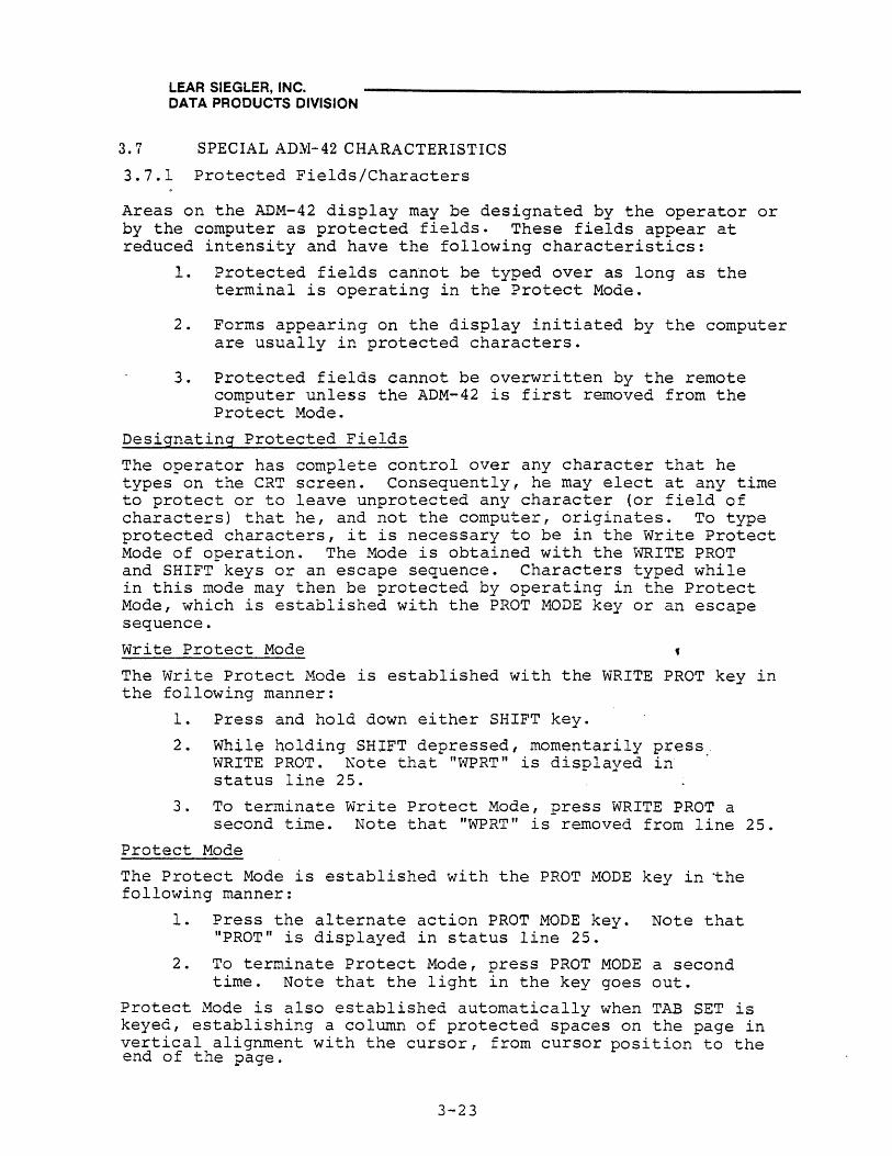
LEAR SIEGLER, INC. DATA PRODUCTS DIVISION
3.7 SPECIAL ADM-42 CHARACTERISTICS
3.7.1 Protected Fields/Characters
Areas on the ADM-42 display may be designated by the operator or by the computer as protected fields. These fields appear at reduced intensity and have the following characteristics:
1. Protected fields cannot be typed over as long as the terminal is operating in the Protect Mode.
2. Forms appearing on the display initiated by the computer are usually in protected characters.
3. Protected fields cannot be overwritten by the remote computer unless the ADM-42 is first removed from the Protect Mode.
Designating Protected Fields
The operator has complete control over any character that he types on the CRT screen. Consequently, he may elect at any time to protect or to leave unprotected any character (or field of characters) that he, and not the computer, originates. To type protected characters, it is necessary to be in the Write Protect Mode of operation. The Mode is obtained with the WRITE PROT and SHIFT keys or an escape sequence. Characters typed while in this mode may then be protected by operating in the Protect Mode, which is established with the PROT MODE key or an escape sequence.
Write Protect Mode
The Write Protect Mode is established with the WRITE PROT key in the following manner:
1. Press and hold down either SHIFT key.
2. While holding SHIFT depressed, momentarily press. WRITE PROT. Note that "WPRT" is displayed in status line 25.
3. To terminate Write Protect Mode, press WRITE PROT a second time. Note that "WPRT" is removed from line 25.
Protect Mode
The Protect Mode is established with the PROT MODE key in the following manner:
1. Press the alternate action PROT MODE key. Note that "PROT" is displayed in status line 25.
2. To terminate Protect Mode, press PROT MODE a second time. Note that the light in the key goes out.
Protect Mode is also established automatically when TAB SET is keyed, establishing a column of protected spaces on the page in vertical alignment with the cursor, from cursor position to the end of the page.
3-23
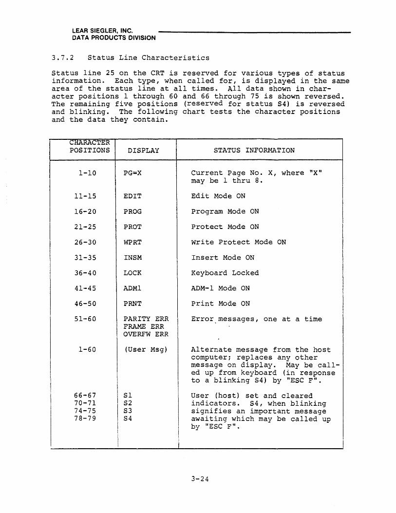
LEAR SIEGLER, INC. DATA PRODUCTS DIVISION
3.7. 2 Status Line Characteristics
Status line 25 on the CRT is reserved for various types of status informatione Each type, when called for, is displayed in the same area of the status line at all times. All data shown in character positions 1 through 60 and 66 through 75 is shown reversed. The remaining five positions (reserved for status S4) is reversed and blinking. The following chart tests the character positions and the data they contain.
CHARACTER POSITIONS
1-10
11-15
16-20
21-25
26-30
31-35
36-40
41-45
46-50
51-60
1-60
66-67 70-71 74-75 78-79
DISPLAY
PG=X
EDIT
PROG
PROT
WPRT
INSM
LOCK
ADMl
PRNT
PARITY ERR FRAME ERR OVERFW ERR
(User Msg)
Sl S2 S3 S4
STATUS INFORMATION
Current Page No. X, where "X" may be 1 thru 8.
Edit Mode ON
Program Mode ON
Protect Mode ON
write Protect Mode ON
Insert Mode ON
Keyboard Locked
ADM-l Mode ON
Print Mode ON
Error messages, one at a time
Alternate message from the host computer; replaces any other message on display. May be called up from keyboard (in response to a blinking S4) by "ESC F".
User (host) set and cleared indicators. S4, when blinking signifies an important message awaiting which may be called up by "ESC F".
3-24
LEAR SIEGLER, INC. DATA PRODUCTS DIVISION
3.8 PROGRAMMING CONSIDERATIONS
The ADM-42 contains electronic circuitry which allows the remote computer full control over the data terminal. All control operations which are possible from the keyboard can also be executed from the computer. At the keyboard these control operations are initiated and/or terminated by using the CT.RL, ESC, and Fl throu.gh F16 function keys in combination with one or more alpha numeric or special operation keys. The coding thus produced duplicates the coding required or produced by the computer; the discussion that follows, however, focuses on the methods of producing the codes using keyboard procedures. The types of special control operation available, toaether with the coding required, are listed in table 3-3, and di~cussed as required in paragraphs 3.8.1 through 3.8.10.
3.8.1 CTRL Key Operations
The CTRL key is always used in combination with an alpha or special character key. Pressing the CTRL key modifies the ASCII code of the selected standard character to a special control operation code. Figure 3-2 shows a portion of the standard ADM-42 graphic set, along with the hex coding ~olumns 4 and 5) which identifies and locates the standard characters. Columns of a and 1 of the chart show 32 CTRL codes and the modified characters (symbols) produced by using the CTRL key; these symbols occupy the same relative positions in the columns as the standard keyboard characters they mOdify. Pressing the CTRL key will cause the CTRL code to be applied only to the terminal; no code would be transmitted to the computer. In Program Mode (refer to paragraph 3.6) the CTRL character to be transmitted to the computer will be written on the CRT screen as the character is keyed.
3-25

HEX
a
1
2
3
4
5
6
7
8
9
A
B
C
0
E
F
LEAR SIEGLER, INC. OAT A PRODUCTS DIVISION
FUNCTION GRAPHIC CHARACTER SET
a 1 2 3 4 5 6
BITS BITS 4321 765 000 001 010 all 100 101 110
... 0000 NUL DLE a @ P
0001 SOH OC1 1 1 A Q a
0010 STX DC2 " 2 B R b
0011 ETX OC3 # 3 C S c
0100 EOT OC4 $ 4 0 T D
0101 ENQ NAK % 5 E U e
0110 ACK SYN & 6 F V f
0111 BEEP ETB , 7 G W g
l ..... ) 1000 BS CAN ( 8 H X h
(SKIP) 1001 HT EM ) 9 I y i
1010 LF ( , ) SUB * : J Z j
1011 VT ( .) ESC + ; K [ k
\ 1100 FF ( .... ) FS < L 1 ,
1101 CR GS - = M J In (HUM.t:.;J
> 1110 SO RS . N 1\ n
1111 SI (NEW \ ? 0 LINE) US - 0
Figure 3-2. ADM-42 Standard Graphic Character Set, Showing Comparable CTRL Codes
3-26
7
III
P
q
r
s
t
u
v
w
x
y
z
! .1 ,
J /v
DEL
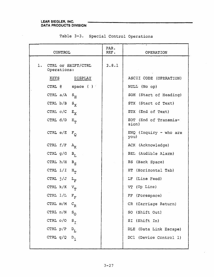
LEAR SIEGLER, INC. DATA PRODUCTS DIVISION
Table 3-3. Special Control Operations
PAR. CONTROL REF. OPERATION
-
1. CTRL or SHIFT/CTRL 3.8.1 Operations:
KEYS DISPLAY ASCII CODE (OPERATION)
CTRL @ space ( ) NULL (No op)
CTRL a/A SH SOH (Start of Heading)
CTRL biB Sx STX (Start of Text)
CTRL c/C EX ETX (End of Text) I
CTRL diD ET EOT (End of Transmis-sion)
CTRL e/E FQ ENQ (Inquiry - who are you)
CTRL f/F ~ ACK (Acknowledge)
CTRL giG BL BEL (Audible Alarm)
CTRL hlH BS BS (Back Space)
CTRL ill HT HT (Horizontal Tab)
CTRL j/J LF LF (Line Feed)
CTRL k/K VT VT (Up Line)
CTRL l/L FF FF (Forespace)
CTRL m/M CR CR (Carriage Return)
CTRL n/N So SO (Shift Out)
CTRL 0/0 SI SI (Shift In)
CTRL piP DL DLE (Data Link Escape)
CTRL q/Q Dl DCI (Device Control 1)
3-27

LEAR SIEGLER, INC. DATA PRODUCTS DIVISION
Table 3-3. Special Control Operations (cont'd)
PAR. CONTROL REF. OPERATION
1. CTRL or SHIFT/CTRL 3.8.1 Operations (cont I d) :
KEYS DISPLAY ASCII CODE (OPERATION) --CTRL r/R D2 DC2 (Device Control 2)
CTRL siS D3 DC3 (Device Control 3)
CTRL tiT D4 DC4 (Turns Printer buffer off-line; Printer continues printing until buffer is empty.)
CTRL u/U N NAK (Not Acknowledged) K
CTRL v/V Sy SYN (Synchronous Idle)
CTRL w/W EB ETB (End of Transmission Block)
CTRL x/X CN I I CAN (Cancel)
I CTRL y/Y EM EM (End of Medium) I
! I CTRL z/Z S SUB (Substitute) B
CTRL [" EC ESC (Escape Sequence)
CTRL "- FS FS (File Separator)
CTRL J Gs GS (Group Separator)
CTRL A Rs RS (Cursor HOME)
CTRL - US (New Line)
3-28

LEAR SIEGLER, INC. DATA PRODUCTS DIVISION
Table 3-3. Special Control Operations (cont'd)
CONTROL
2. ESC Key Operations:
KEYS OPERATION
ESC [ ]
ESC l~ULT ESC M (*)
3. Function PI thru Fl6 Key Operations:
KEYS OPERATION
FI thru FUNKEY Fl6 (unshifted)
SHIFT/FI FUNKEY thru Fl6
ESC ! [] PRGM FNCTN
ESC [] EVOKE FNCTN
PAR. REF.
3.8.2
3.8.3
3-29
OPERATION
DESCRIPTION
Escape Sequence defined by [characters representing ASCII codes desired] .
Perform multiple escape sequences one at a time without keying "ESC" each time (* = successive Escape Sequence characters). Operation is terminated by any control characters.
For special-character operations (primarily for transmission) .
DESCRIPTION
Transmits "SOH/Character (@ thru O)/CR".
Transmits "SOH/Character (' thru o)/CR".
Program and/or display FUNKEY [characters for FI thru F16] .
Evoke message stored under [FI thru Fl6 character]
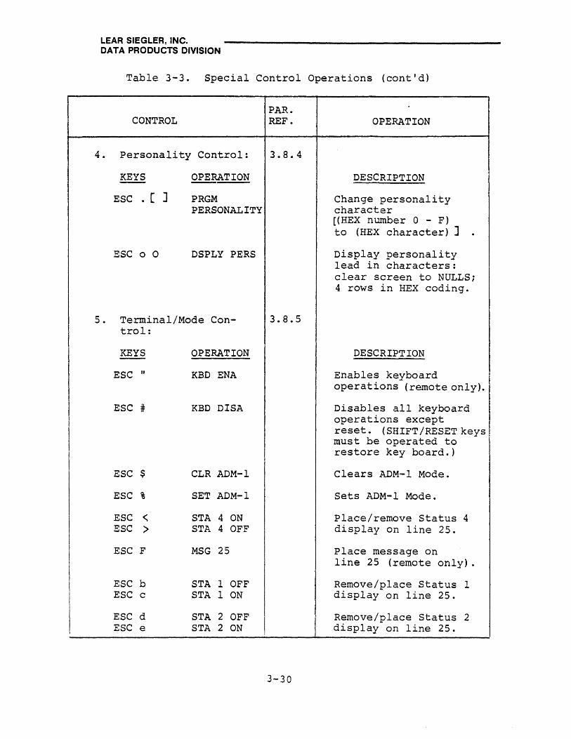
LEAR SIEGLER, INC. DATA PRODUCTS DIVISION
Table 3-3. Special Control Operations (cont'd)
PAR. CONTROL REF .. OPERATION
4. Personality Control: 3.8e4·
KEYS OPERATION DESCRIPTION
ESC . [ ] PRGM Change personality PERSONALITY character
[(HEX number 0 - F) to (HEX character) ] .
ESC 0 0 DSPLY PERS Display personality lead in characters: clear screen to NULLS; 4 rows in HEX coding.
5 . Terminal/Mode Con- 3.8.5 trol:
KEYS OPERATION DESCRIPTION
ESC n KBD ENA Enables keyboard operations (remote only).
ESC # KBD DISA Disables all keyboard operations except reset. (SHIFT /RESET keys must be operated to restore key board.)
ESC $ CLR ADM-l Clears ADM-l Mode.
ESC % SET ADM-l Sets ADM-l Mode.
ESC < STA 4 ON Place/remove Status 4 ESC > STA 4 OFF display on line 25.
ESC F MSG 25 Place message on line 25 (remote only).
ESC b STA 1 OFF Remove/place Status 1 ESC c STA 1 ON display on line 25.
ESC d STA 2 OFF Remove/place Status 2 ESC e STA 2 ON display on line 25.
3-30
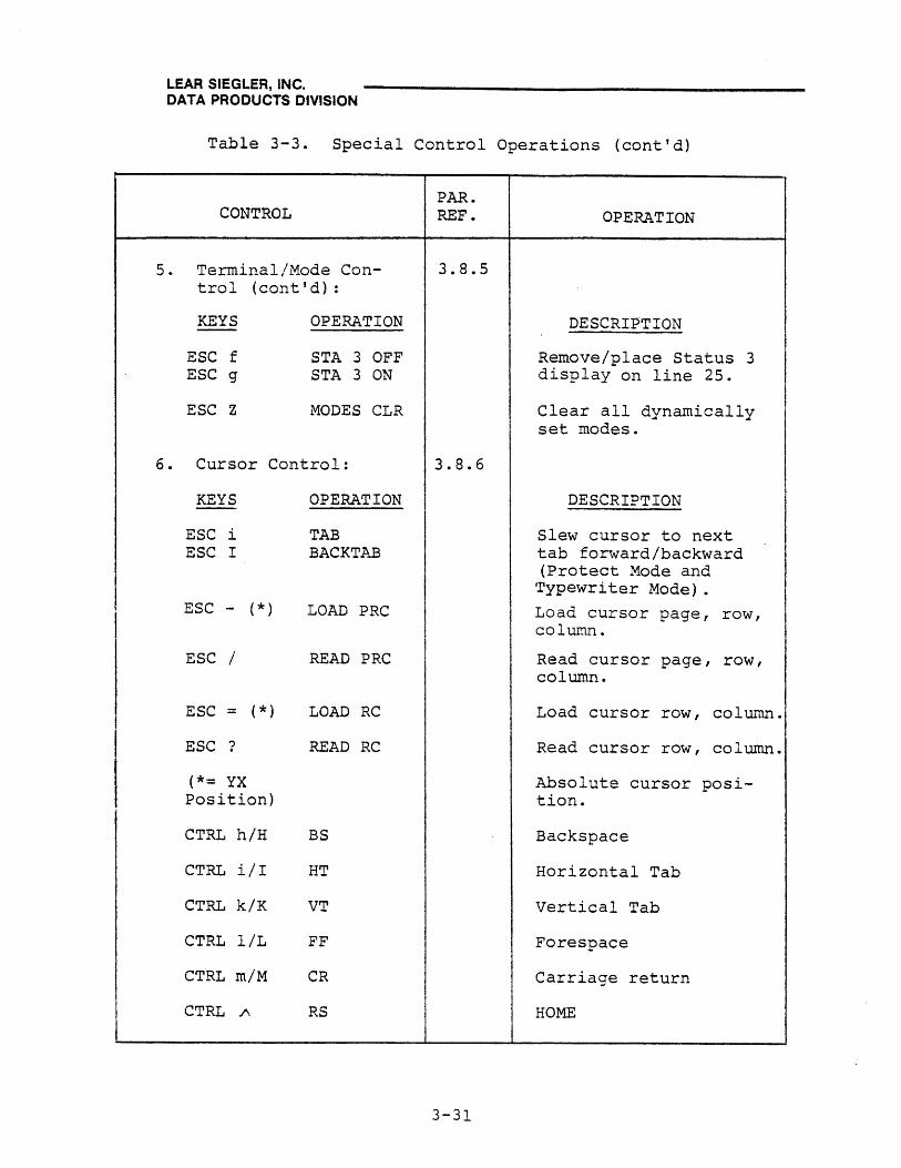
LEAR SIEGLER, INC. DATA PRODUCTS DIVISION
Table 3-3. Special Control Operations (cont'd)
5.
CONTROL
Terminal/Mode Control (cont'd):
KEYS
ESC f ESC g
ESC Z
OPERATION
STA 3 OFF STA 3 ON
~10DES CLR
6. Cursor Control:
KEYS
ESC i ESC I
ESC - (*)
ESC /
ESC = ( *)
ESC ?
(*= YX Position)
CTRL h/H
CTRL i/I
CTRL k/K
CTRL l/L
CTRL m/M
CTRL /\
OPERATION
TAB BACKTAB
LOAD PRC
READ PRC
LOAD RC
READ RC
BS
HT
VT
FF
CR
RS
PAR. REF.
3.8.5
3.8.6
3-31
OPERATION
DESCRIPTION
Remove/place Status 3 display on line 25.
Clear all dynamically set modes.
DESCRIPTION
Slew cursor to next tab forward/backward (Protect Mode and
Typewriter Mode) .
Load cursor page, row, column.
Read cursor page, row, column.
Load cursor row, column.
Read cursor row, column.
Absolute cursor position.
Backspace
Horizontal Tab
Vertical Tab
Forespace
Carriage return
HOME

LEAR SIEGLER, INC. DATA PRODUCTS DIVISION
Table 3-3. Special Control Operations (cont'd)
CONTROL
7. For.mat Control:
KEYS
ESC &
ESC I
ESC (
ESC )
ESC I
ESC U
ESC V
OPERATION
SET PROTM
CLR PROTM
CLR WPROT
SET WPROT
BAC K TAB
SET PGM MODE
SET PROT COL SP
ESC X CLR PGM MODE
ESC i TAB
ESC u CLR PGM MODE
ESC v SET ATUO PG
ESC w CLR AUTO PG
ESC 3 P SET TAB MD
ESC 3 [J SET MODULUS TAB
ESC 3 Sp RESET TAB MODE
In Typewriter Tab Mode~
ESC 2 CLR TAB
PAR REF.
3.8.7
3-32
OPERATION
DESCRIPTION
Set Protect Mode.
Clear Protect Mode.
Clear Write Protect Mode.
Set Write Protect Mode.
Slew cursor backward to next tab.
Set Program Mode.
Set column of protected spaces for tabs. Sets Protect Mode.
Clear Program Mode.
Slew cursor forward to next tab.
Clear Program Mode.
Set AUTO PAGE function.
Clear AUTO PAGE function.
Set typewriter Tab Mode, except when Protect Mode is set.
Set Tab at Modulo D.-791 • (See figure 3-4).
Resets all Typewriter Mode settings.
Clear column of tabs under cursor for entire page.

LEAR SIEGLER, INC. DATA PRODUCTS DIVISION
Table 3-3. Special Control Operations (cont'd)
CONTROL
7. Format Control (cont'd) :
KEYS OPERATION
ESC 1 SET TAB
ESC 0 CLR TABS
CTRL @ NULL
CTRL alA SOH
CTRL biB STX (SOM) or ESC 8
CTRL c/C ETX (EOM) or ESC 9
CTRL diD EOT
CTRL w/W ETB
CTRL y/Y EM
CTRL \ FS
CTRL ] GS
CTRL 1\ RS
CTRL - US
PAR. REF.
3.8.7
3-33
OPERATION
DESCRIPTION
Set column of tabs under cursor for entire page.
Clear all typewriter tabs except SET MODULUS tabs.
No Ope
Start of heading.
Start of text (message) .
End of text (message) .
End of transmission.
End of transmission block.
End of message.
Field Separator.
Group Separator.
Cursor HOME.
New Line.
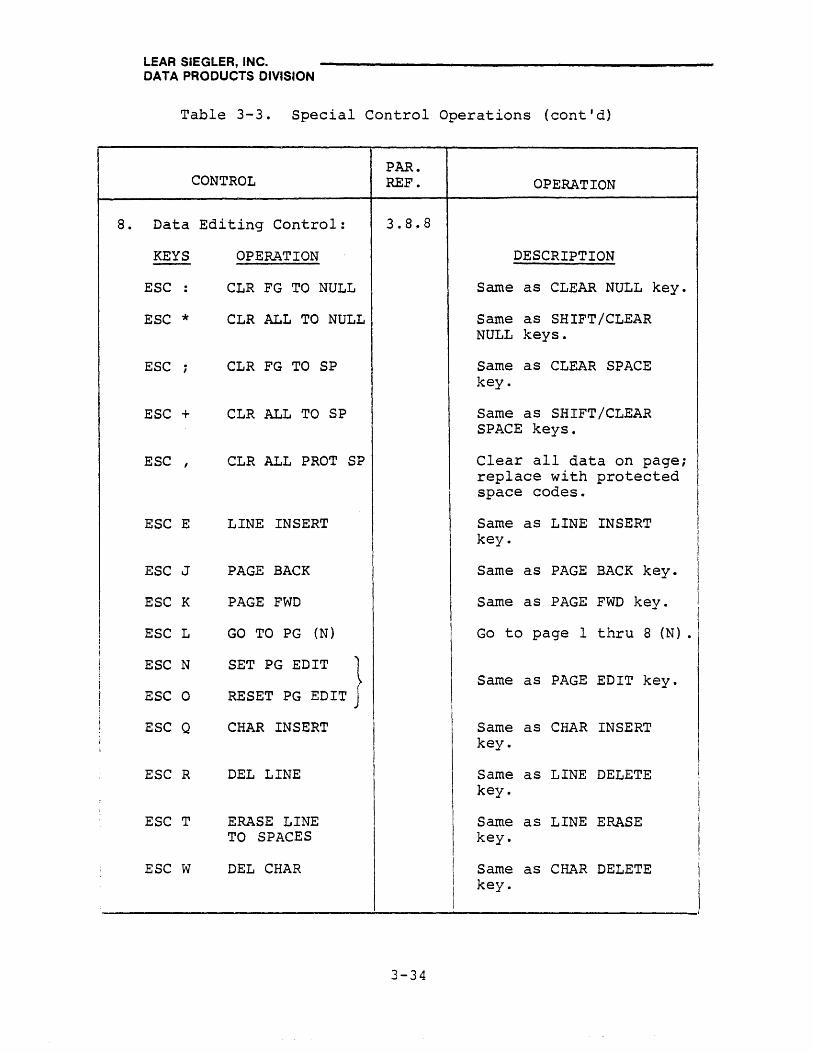
f
LEAR SIEGLER, INC. DATA PRODUCTS DIVISION
Table 3-3. Special Control Operations (cont'd)
CONTROL
8. Data Editing Control:
KEYS
ESC :
ESC *
ESC ;
ESC +
ESC ,
ESC E
ESC J
ESC K
ESC L
ESC N
ESC 0
ESC Q
ESC R
ESC T
ESC W
OPERATION
CLR FG TO NULL
CLR ALL TO NULL
CLR FG TO SP
CLR ALL TO SP
CLR ALL PROT SP
LINE INSERT
PAGE BACK
PAGE FWD
GO TO PG (N)
SET PG EDIT }
RESET PG EDIT
CHAR INSERT
DEL LINE
ERASE LINE TO SPACES
DEL CHAR
PAR. REF.
3.8.8
OPERATION
DESCRIPTION
Same as CLEAR NULL key.
Same as SHIFT/CLEAR NULL keys.
Same as CLEAR SPACE key.
Same as SHIFT/CLEAR SPACE keys.
Clear all data on page; replace with protected space codes.
Same as LINE INSERT key.
Same as PAGE BACK key.
Same as PAGE FWD key. I
Go to page 1 thru 8 (N) .1
Same as PAGE EDIT key.
Same as CHAR INSERT key.
Same as LINE DELETE key.
Same as LINE ERASE key.
Same as CHAR DELETE key.
------------------------------~--------------------------------~
3-34

LEAR SIEGLER, INC. DATA PRODUCTS DIVISION
Table 3-3. Special Control Operations (cont'd)
CONTROL
8. Data Editing Control (cont'd) :
KEYS
ESC Y
ESC m (Y) (X)
ESC q
ESC r
ESC t
ESC Y
OPERATION
ERASE PG TO SPACES
WRITE MULT CHAR
SET INS MODE
CLR INS MODE
LINE ERASE NULL
ERASE PG TO NULL
9. Data Transmission Control:
KEYS OPERATION
ESC 4 SEND LINE FG
ESC 5 SEND PAGE FG
ESC 6 SEND LINE ALL
ESC 7 SEND PAGE ALL
ESC 8 WRITE SOM (STX)
ESC 9 WRITE EOM (ETX)
ESC B SET BLOCK
PAR. REF.
3.8.8
3.8.9
3-35
OPERATION
DESCRIPTION
Same as pApE ERASE key.
Write ASCII character (X) a modulo number of times (Y). (See figure 3-4).
Set Insert Mode.
Clear Insert Mode.
Same as SHIFT/LINE ERASE keys.
Same as SHIFT/PAGE ERASE keys.
DESCRIPTION
Same as SEND LINE key.
Same as SEND PAGE key.
Same as SHIFT/SEND LINE keys.
Same as SHIFT/SEND PAGE keys.
Write STX character on screen.
Write ETX character on screen.
Set Block Mode.

LEAR SIEGLER, INC. DATA PRODUCTS DIVISION
Table 3-3. Special Control Operations (cont'd)
CONTROL
9. Data Transmission Control (cont I d) :
KEYS
ESC C
ESC DH
ESC DF
ESC P
ESC S
ESC a 0 ESC a 1
ESC P
ESC s
ESC @
ESC [ (Mult. )
ESC / [1 (HEX 31) thru 8 (HEX 38)]
ESC ?
OPERATION
SET CONY
H DUPL
F DUPL
PRNT PG ALL
SEND MSG FG
AUX CTRL OFF AUX CTRL ON
PRNT UNF
SEND MSG ALL
PRNT PROT AS SPACES
PRNT CTRL
READ PRC
READ RC
PAR. REF.
3.8.9
3-36
OPERATION
DESCRIPTION
Set Conversation Mode.
Set dynamic half duplex mode.
Set dynamic full duplex mode.
Print all data on page.
Same as SEND MSG key.
Disables/enables RCVE data via ASYNC PRINTER port interface.
Same as SHIFT/PRINT key.
Same as SHIFT/SEND MSG keys.
Print protected data as spaces, similar to ESC P.
Buffered Print Mode: establish printing characteristics using multiple characters.
Read cursor row (Y) and column (X) on [selected page (1 thru 8)].
Read cursor row (Y) and column (X) on current page.
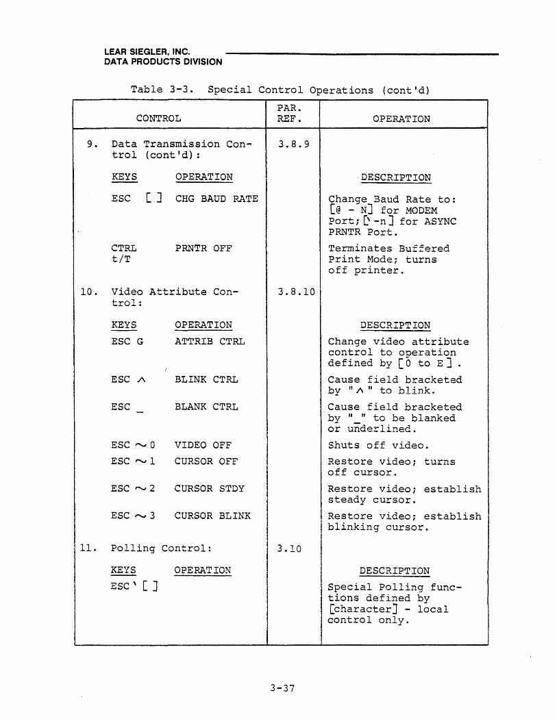
LEAR SIEGLER, INC. DATA PRODUCTS DIVISION
Table 3-3. Special Control Operations (cont'd)
CONTROL
9. Data Transmission Control (cant I d) :
KEYS OPER.~TION
ESC [J CHG BAUD RATE
CTRL tiT
PRNTR OFF
10. Video Attribute Con-I trol:
KEYS
ESC G
ESC /\
ESC
ESC "-wI 0
ESC "-wI 1
ESC"""'" 2
ESC,......., 3
OPERATION
ATTRIB CTRL
BLINK CTRL
BLANK CTRL
VIDEO OFF
CURSOR OFF
CURSOR STDY
CURSOR BLINK
11. Polling Control:
KEYS OPERATION
ESC' [ ]
PAR. REF.
3.8.9
3.8.10
3.10
3-37
OPERATION
. DESCRIPTION
Change Baud Rate to: [@ - NJ for MODEM Port i [\ -nJ for ASYNC PRNTR Port.
Terminates Buffered Print Mode; turns off printer ..
DESCRIPTION
Change video attribute control to operation defined by [0 to E ] •
Cause field bracketed by "A" to blinke
Cause field bracketed by " " to be blanked or underlined.
Shuts off video.
Restore video; turns off cursor.
Restore video; establish steady cursor.
Restore video; establish blinking cursor.
DESCRIPTION
Special Polling functions defined by [character] - local control only.

LEAR SIEGLER, INC. DATA PRODUCTS DIVISION
3.8.2 ESC Key Operations
The ESC key is another key that is always used in combination with one or more alphanumeric or special character keys to produce "escape sequence" operations. Figure 3-3 shows the various escape sequences available in the ADM-42 and the ASCII characters which are required to initiate the sequence. Escape sequences are typically initiated by the computer. When initiated from the keyboard, the escape character and the desired ASCII character can be transmitted to the computer. In Program Mode the escape sequence characters are also displayed on the CRT screen.
Multiple escape sequences can be programmed without preceding each ASCII character with the ESC key, thus facilitating operations which require more than one escape sequence. This operation i~ activated by ESC M and terminated by pressing any control key (CR, LF, HOME, CTRL, etc.).
3.8.3 Function Key (FUNKEY) Operations
Standard FUNKEY Operations
Functions keys Fl thru F16 are used to transmit specific codes. These codes may be employed by the programmer in any way that will simplify or expedite work. Typically, the codes used are not committed for any special purpose until assigned by the programmer. Another 16 characters are available by pressing and holding SHIFT while operating a function key. When pressed, each key Fl thru Fl6 causes a three-character code to be produced: "SOH/ASCII Character/CR". The special-function ASCII characters available are as follows:
FUNKEY FI F2 F3 F4 FS F6 F7 F8 F9 FlO FII F12 F13 Fl4 FIS Fl6
UNSHIFT @ A B C D E F G H I J K L M N 0
SHIFTED \ a b c d e f g h i j k 1 m n 0
To transmit a FUNKEY code using an FI through F16 key, simply press the appropriate key. The SOH code will be transmitted to the host.
To transmit a FUNKEY code using an escape sequence, execute "ESC\[@ thru 0]" for unshifted function, or "ESC \ [\ thru 0 J" for shifted function. The SOH code will be transmitted to the host.
Note
In the above operations~ the 3Z-or 63-oharaoter storage option is not instaZZed.
3-38

LEAR SIEGLER, INC. DATA PRODUCTS DIVISION
Optional FUNKEY Operations
When the optional 31- or 63-character option is installed, it is possible to store a message under anyone or combination of Fl thru F16 function keys. Thus, whenever the (first) key is called for either by a key operation or escape sequence, the stored message will be transmitted either to the host computer or to an auxiliary device. The d~stination of the message is established atthe time it is written by preceding the message with an liH", "K", or "A", as follows:
• An "H" signifies that the message is to be transmitted only to the host computer when evoked. Message is not displayed on the ADM-42 screen.
• A "K" signifies that the message is for display on the ADM-42 screen. Message is transmitted to the host computer only if CONV MODE is set.
• An "A" signifies that the message is to be transmitted only to the auxiliary printer when evoked. Message ~s not displayed on the ADM-42 screen.
Storing FUNKEY Message Using CTRL Key
Proceed as follows:
1. Execute "ESC *" (CLEAR ALL NULL) to clear the screen to null codes.
2. Terminate CONV MODE, if set.
3. Enter "H", "K", or "A" as desired.
4. Enter the message just as it is to be stored. Cursor should be at the end of the message.
5. Execute "CTRL / [Fl thru F16]" (unshifted or shifted) to store the message under the selected FUNKEY.
3-39

LEAR SIEGLER, INC. DATA PRODUCTS DIVISION
ESCAPE SEQUENCE
HEX 2 3 4 5 6 7
0 ~ CLEAR TABS I-tJ PRINT PROT
AS SPACES* ~ PRINT
ALL PAGE~ POLLING
I ADDRESS* W PRINT
(UNF)
1 W-J PROG i-LJ SET TAB ~ ~CHAR ~AUX --9...1 INSERT FNCTN* INSERT CONTROL * MODE ON
2 ~ ENABLE ~ CLEAR TAB ~ SET BLOCK ~LINE ~ STATUS W:.J INSERT
KEYBD DELETE 1 OFF MODE OFF
3 WL1 DISABLE KEYBD
WJ SET TAB MODE *
f-£..J SET CONV ~SEND ~ STATUS I-.LJ SEND MSG FG 1 ON MSG ALL
4 ~ CLEAR ~ SEND ~ DUPLEX ~LINE ~ STATUS ~LINE
ADMl M LINE FG CONTROL * ERASE SP 2 OFF ERASE Nfll.
5 WSET ~SEND ~ LINE ~ PROGM ~ STATUS ~ PROGM
ADMI M PAGE FJi INSERT MODE ~F.'T' 2 0111 MOnF. rr.R
b W-J SET ~ SEND ~ MESSAGE ~ SET PROT ~ STATUS ~ AUTO PAGE PROTECT LINE ALL TO ROW 25* COL OF SP 3 OFF ON
7 ~ RESET W SEND i--GJ ATTRIBUTE ~CHAR I-2-J STATUS ~ AUTO PAGE
PROTECT PAGE ALL CONTROL * DELETE 3 ON OFF
8 W-J CLEAR
WPROT ~ WRITE
SOM (STX) ~ ~ PROGM MODE CLR
~ ~
9 I-2-J SET WPROT
~ WRITE (ETX) EOM
~ BACKTAB ~ ERASE PAGE SP
~ SKIP (TAB)
~PAGE ERASE NUL
~ CLR ALL W CLR FG A TO NUL NUL
~PAGE BACK
~MODES CLEAR
~ W-J B ~ CLR ALL W CLR FG ~ PAGE ~ PRINT W W-J
TO SPACE SPACE FWD CONTROL * ~ CLR ALL ~ STATUS f-.!:J GO TO PAGE ~ ENVOKE ~ ~ CHANGE
C TO PROT SP 4 ON N (1-8)* FUNCTION * BAUD RATE*
D ~ LOAD PG ~ LOAD ~ MULT WJ ~ WRITE ~ & CURS CURSOR ESC* MULT CHAR*
E W PROGRAM ~ STATUS WU SET PAGE ~ BLINK ~ ~_VIDEO &
PERSONALITY* 4 OFF EDIT ~UR.SOR N .' Kl
F ~ SEND PG
& CURS WJ SEND
CURSOR ~ RESET
PAGE EDIT ~BLANK ~ DISPLAY ~
CONTROL IT,ITY
*Requires additional characters to complete sequence
Figure 3-3. ADM-42 Escape Sequence Characters, With HEX Coding
3-40

LEAR SIEGLER, INC. DATA PRODUCTS DIVISION
Erasing FUNKEY Messaqe Using CTRL Key
Proceed as follows:
1. Execute "ESC *" (CLEAR ALL TO NULL) .
2. Enter "X".
3. Execute "CTRL / [Fl thru F16] II to erase the message stored under the selected FUNKEY.
Storing FUNKEY Message Using Escape Sequences
Proceed as follows:
1. Execute "ESC *" (CLEAR ALL TO NULL) .
2. Terminate CONV MODE, if set.
3. Enter "H", "K", or "A": as de'sired ..
4. Enter the message just as it is to be stored. Cursor should be at the end of the message (after the last character) .
5. Execute "ESC ! [@ thru 0 ] " to store the message under the selected unshifted FUNKEY, or "ESC ! [, thru oJ" to store the message under the selected shifted FUNKEY.
Erasina Specific Stored FUNKEY Message Using Escape Sequences
Proceed as follows:
1. Execute "ESC * II (CLEAR ALL TO NULL) .
2. Execute "ESC ! [@ thru 0] " to erase the message stored under the selected unshifted FUNKEY, or "ESC ! [, thru o]"to erase the message stored under the selected shifted FUNKEY.
Erasing All Stored FUNKEY Messages Using Escape Sequences
To erase all messages stored under the Fl thru FI6 function keys, execute: "ESC ! X".
3-41
LEAR SIEGLER, INC. DATA PRODUCTS DIVISION
Displaying All Stored FUNKEY Messages Using Escape Sequences
Messages stored under function keys Fl thru F16 may be displayed on the ADM-42 screen without transmitting 5 The display will list all FUNKEY FI thru F16 messages, one message per line (63 characters, maximum). If the FUNKEY does not contain a message, "X" will be displayed, instead. To display messages stored under FUNKEY, proceed as follows:
1. Terminate CONV MODE, if set.
2. Execute: "ESC! 1" for unshifted (@ thru 0) FUNKEY display, or "ESC! 2" for shifted ('thru 0) FUNKEY display.
Evoking Stored FUNKEY Message Using Escape Seguences
A message stored under a specific FUNKEY may be "evoked" (called up) for transmission by means of an escape sequence. The evoke message, is transmitted and/or displayed in accordance with the "H", "K", or .. IA" instructions which precede the stored message. Toevo.~e a stored message, proceed as follows:
1. Set CONV MODE (ESC C), if not set.
2 . Execute: "ESC ,(@ thru 0] II for an unshifted FUNKEY message or "ESC\[ thru 0] " for a shifted message.
3.8.4 Personality Control Operations
The personality attributes which were assigned (or unspecified) to the ADM-42 terminal at the time of purchase can be temporarily modified at any time by the operator from either the keyboard or the host computer. The temporary or "dynamic" modification, which is terminated when power is removed from the terminal, is provided to allow the operator to alter certain character codes which may (for example) cause computer program interrupts if used as established. A personality change can be effected from the keyboard by entering "ESC." followed by the HEX number of the code to bel changed, then one or more HEX character codes which identify the new ASCII dynamic character(s). The HEX character in the ADM-42 standard graphic set (figure 3-2). The keyboard operations which effect the dynamic personality change are not written on the CRT screen or transmitted to the host computer.
The personality attributes applicable to the terminal may be displayed by executing an "ESC 00" sequence. The terminal will clear screen to nulls, then display four rows of personality characters, 16 HEX bytes to a row. "(ESC 09" displays the date of the firmware.) The information contained in each row is as follows:
3-42
LEAR SIEGLER, INC. DATA PRODUCTS DIVISION
• The first row displays all installed in the terminal.
the personality defaults This row is non variable.
• The second row displays all the personality defaults which may be dynamically changed.
• The third and fourth rows are not defined.
The personality defaults subject to dynamic change are initiated by an "ESC.[]" sequence. Within the brackets are two character codes: HEX number (0 to F) which expresses the personality default to be changed; followed by the HEX code of the ASCII replacement character, as follows:
Escape Lead-In and Transmit Characters
The sequence "ESC. [0 (HEX)]" adds a new escape lead-in character to the standard escape character. (The standard character is a bona fide computer character and cannot be changed.) Thus, the terminal will execute an escape sequence in response to the new character, as well as to the standard ESC character. During transmission, the new character will be transmitted in place of the standard character whenever ESC is called for.
Note
The dynamic personality change associated with the escape lead-in character is different from the other dynamic personality changes 3 in th~t the standard lead-in character cannot be changed3 only added to. In all other dynamic personality changes3 the standard character is temporarily replaced by the new character.
End Block Characters
"ESC. [1 (HEX)]" changes the standard End Block character to the selected (HEX Code) character. A second End Block character may be added using an "ESC. [2 (HEX)]" character. The second End Block character may be a new line or line feed character if desired. Both End Block characters would be imbedded in the text whenever the first End Block character was called for.
New Line Characters
"ESC. [3 (HEX)]" changes the standard New Line character and "ESC. [4 (HEX)]" adds a second New Line character, in the same manner as for End Block characters, above.
3-43

LEAR SIEGLER, INC. DATA PRODUCTS DIVISION
other Personality Characters
• "ESC. [5 (HEX)]" establishes a new character for the standard Field Separator character.
• "ESC. [6 (HEX)]" establishes a new character for the standard FUNCTION lead-in character.
• "ESC. [7 (HEX)]" establishes a character which would be written on the screen when a parity error is sensed (not provided on standard ADM-42). The parity error character should be one the customer does not normally use.
• "ESC. [8 (HEX)]" establishes a new character for the character previously assigned to the Clear Screen command (usually a space code). The new character may be NULL, period, underline, etc. Only LINE DELETE, LINE INSERT, and CHARACTER DELETE operations are affected.
• "ESC. [9 (HEX)]" establishes the delay, in milliseconds, between the Request to Send (RTS) signal and the actual beginning of transmission (CTS) in a Block Mode transmission.
The HEX number is a two-character expression where in the number, multiplied by 2 is the value of the delay, in milliseconds. Thus: the HEX number 05 represents a delay of 10 milliseconds .
• "ESC. [B (HEX)]" establishes certain conditions which are applicable when the Polling Option is in effect. The HEX code identifies a firmware bit which is set = 1 in order to establish the desired condition. Multiple conditions may be establisehed by using the appropriate HEX codes; however, all bits must be set at the same time.
HEX CODE
BOI
B02
B04
BIT SET=l CONDITION
o Headers are required in ADM-42 response; otherwise headers are not required (ADM-2 compatible response) .
1 Any keyboard key may be used to switch from LOCAL to POLLING mode; otherwise, CONV MODE key must be used.
2 Remote FAST SELECT command is conditional; otherwise, is unconditional.
3-44

LEAR SIEGLER, INC. DATA PRODUCTS DIVISION
HEX CODE
BOa
BIO
B20
B40
BIT SET=l
3
4
5
6
CONDITION Terminal automatically returns to LOCAL mode after POLLING message is completed; otherwise, terminal returns to IDLE Mode.
Inhibits transmission of last character (under cursor) in Block Mode; otherwise, last character is sent.
Reserves last page for print buffer.
Enables polling conununications buffer. Lncoming data is held in buffer unt~l message is completed. If there are no errors, message is then placed on screen. Otherwise, incoming data goes directly to screen.
• "ESC. [C (HEX)] n establishes the nu."r~er 01: POLLING transmissions which will be counted before recycling (reoeat transmissions do not increment the transmission number). Transmission numbers are sent only if headers are sent. The two character HEX number (00 -09) establishes the following operations:
COO
COl thru C09
Inhibits the transmission number so that it does not appear in the ADM-42 response to a polling inquiry_
Establishes the maximum number of transmissions to be counted before recycling .. (If the HEX number is 01, the transmission number will alternate between 0 and 1 for each transmission.)
• "ESC. [D (HEX)]" Reserved
• "ESC. [E (HEX)]" establishes which terminal characteristics cannot be altered from the keyboard. The keyboard is locked out for the specified operation. The HEX code identifies a firmware bit which is set=l in order to establish the desired condition. Multiple conditions may be established by using the appropriate HEX codes; however, all bits must be set at the same time.
HEX CODE
EOI
E04
E40
BIT SET=l
o 3
7
CONDITION
Prevents FUNKEY programming from keyboard.
Prevents keyboard programming of the function which inhibits Audio Video Turnoff.
Prevents keyboard progranuning of personality changes.
3-45

LEAR SIEGLER, INC. DATA PRODUCTS DIVISION
Status Control
The availability of four separate messages can be indicated by the displaying of status code 51, S2, S3, or 54, in Status Line 25. A blinking S4 indicates an important message is waiting. An escape sequence is required to call up the waiting message, as follows:
STATUS Sl S2 53 54
ON ESC c ESC e ESC g ESC <
OFF ESC b ESC d ESC f ESC )
In addition to the above status message, an override message may be placed on Status Line 25 by means of a CPU initiated "ESC Fit conunand. All status information displayed on line 25 will be overriden in favor of this message from the host. Any control character will terminate the writing of this message and/or display it in Status Line 25. PAGE FWD (ESC K) or MODES CLEAR (ESC Z) or anything affecting Status Line 25 will clear any status message.
"ESC Zit will clear all modes and operations which have been dynamically set into the terminal.
3.8.6 Cursor Control Operations
Control of the cursor can be initiated at the keyboard using a CTRL or ESC key sequence. The ESC sequence consists of pressing the ESC key followed by one or more alpha or special character keys. The CTRL operation consists of pressing an alpha character key while holding the CTRL key. When initiated, the operation causes the cursor to respond in the same manner as with the labeled operational control keys discussed in paragraph 3.3. (Also, the control code is transmitted during Conversation Mode transmission.) The coding is equivalent to that which the computer transmits to the terminal to control the cursor. Refer to table 3-3 for the list of cursor control codes and to figures 3-2 and 3-3 for the ASCII and HEX codings.
The cursor may be commanded to an absolute CRT screen position which can be defined in terms of its vertical (Y) and horizontal (X) coordinates. In the ADM-42, these coordinates are expressed by two ASCII (HEX) characters in conjunction with an escape sequence, with the vertical (Y) coordinates expressed first. Similarly, the absolute screen position of the cursor may be read by means of another escape sequence. When initiated, the sequence causes the appropriate cursor operation to be executed; the control code is transmitted in Conversation Mode.
3-47
LEAR SIEGLER, INC. DATA PRODUCTS DIVISION
Figure 3-4 shows the absolute X or Y position (1-80 horizontal; 1-24 vertical) and the ASCII (HEX) code assigned to each position. The following escape sequences are used to execute absolute cursor position operations~
• "ESC= (HEX) (HEX)" commands the cursor to the desired row (Y) and column (X) position on the current page.
• "ESC- (1 (HEX 31) thru 8 (HEX 38)] (HEX) (HEX)" commands the cursor to the desired row (Y) and column (X) position on the selected page (1 thru 8).
• "ESC?" reads the cursor row (Y) and column (X) position on the current page.
• "ESC/(l(HEX 31) thru 8(HEX 38}]" reads the cursor row (Y) and column position the selected page (1 thru 8) .
Note The absolute values indioated by (yX)~ above are the vertioal/horizontal soreen coordinates of the cursor position. In machine language~ these coordinates are expressed by an ASCII (HEX) code whioh has been assigned to one of the 80 positions on a line (y ooordinate) or one of the 24 lines (X coordinate). See figure 3-4.
3.8.7 Format Control Operations
The operator can exercise control of the text format on the CRT screen from either the keyboard or the computer. At the keyboard, the operator uses the ESC or CTRL key in combination with alphanumeric or special character keys to establish the selected control sequences. These sequences are listed in table 3-3 and the appropriate ASCII and hex codings are shown in figure 3-2 and 3-3. Using the ESC key executes the selected operation, and causes the escape character and the ASCII character to be transmitted in Conversation Mode.
Several format control operations are available which provide great versatility in setting and using the terminal tabs, as follows:
Protect Mode Tabs
"ESC V" causes a vertical column of protected spaces to be set at the cursor position. The column extends from line containing cursor to line 24. Protect Mode is automatically set. Tabs may be cleared by terminating Protect Mode.
Typewriter Tab Mode Tabs
"ESC 3p" establishes Typewriter Tab Mode, during which tabs may be set and cleared in much the same way as an ordinary typewriter. Typewriter Tab Mode is not operative while Protect Mode is set; however, setting Protect Mode does not clear any typewriter tabs which have been set. Thus, while in Typewriter Tab Mode:
• "ESC 0" Clears all typewriter tabs.
• "ESC 1" Sets a vertical column of tabs at the cursor postion for the entire page.
• "ESC 2" Clears the vertical column of tabs at the cursor positon.
• "ESC 3 Space" Clears Typewriter Tab Mode.
3-48

LEAR SIEGLER, INC. DATA PRODUCTS DIVISION
Modulus Tabs
3.8.8
• "ESC 3 [HEX] II sets vertical columns of tabs on the current page at the position intervals specified by absolute (modulo) value represented by the [HEX] character. (See figure 3-4.) The double HEX byte defines an ASCII character which in turn expresses the number of positions in each tab interval. Thus, HEX 2F (ASCII /) calls for 15 positions between tabs.
• "ESC 3 Space II clears all Modulus Tabs.
Data Editing Control Operations
Data editing using escape sequences accomplishes essentially the same operations as those initiated by means of labeled special editing keys, as described in paragraph 3.4. Table 3-3 lists the previously described operations, as well as several which are available only via escape sequences. The escape-sequence operations take precedence over standard and dynamic personality attributes, unless otherwise specified. CLEAR and ERASE commands, apply only to the page currently being displayed, even if AUTO PAGE is set. The following escape sequences match the indicated special key operations:
• ESC E matches LINE INSERT •.
• ESC J matches PAGE BACK.
• ESC K matches PAGE FWD.
• ESC N matches PAGE EDIT (ON) .
• ESC 0 matches PAGE EDIT (OFF) .
• ESC Q matches CHAR INSERT.
• ESC R matches LINE DELETE
• ESC T matches LINE ERASE.
• ESC W matches CHAR DELETE.
• ESC Y matches PAGE ERASE.
• ESC Y matches SHIFT/PAGE erase.
• ESC t matches SHIFT/LINE erase.
• ESC matches CLEAR SPACE.
• ESC matches CLEAR NULL.
• ESC + matches SHIFT/CLEAR SPACE.
• ESC * matches SHIFT/CLEAR NULL.
3-49
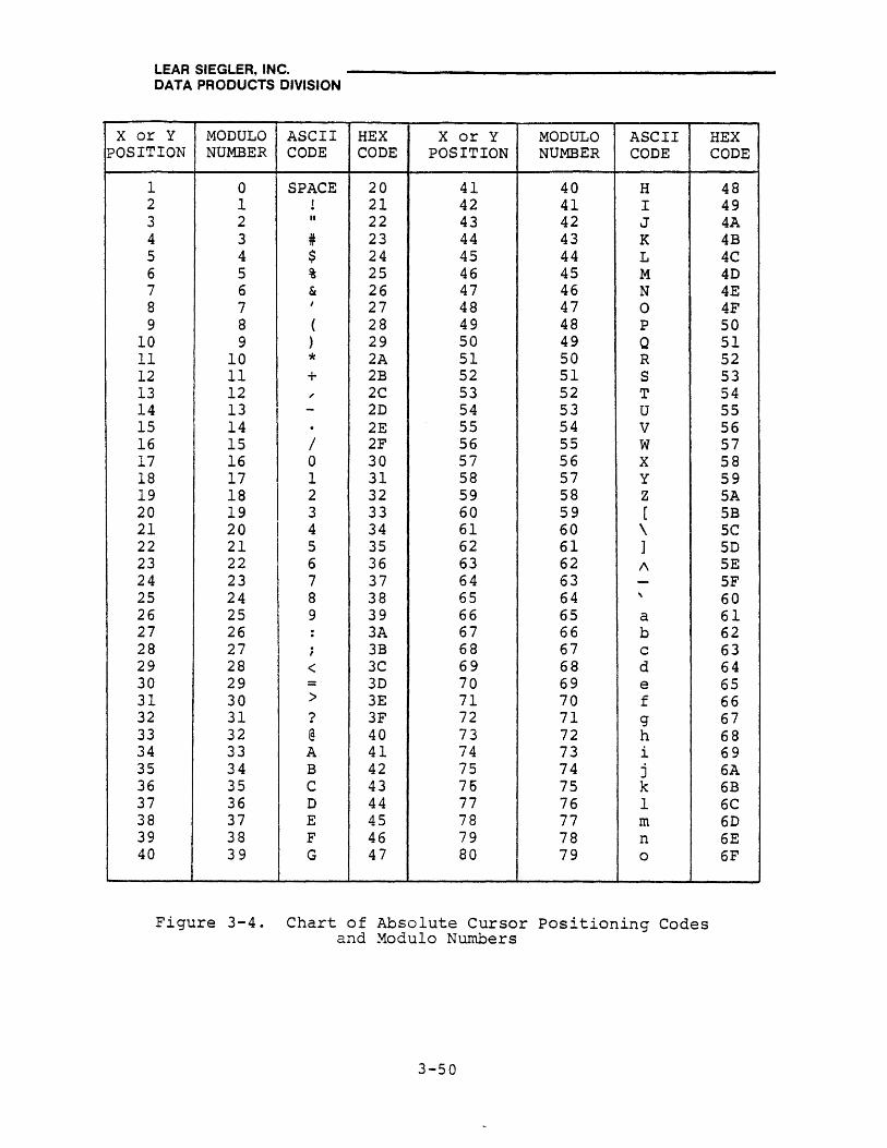
LEAR SIEGLER, INC. DATA PRODUCTS DIVISION
X or Y MODULO ASCII HEX X or Y MODULO ASCII POSITION NUMBER CODE CODE POSITION NUMBER CODE
1 0 SPACE 20 41 40 H 2 1 ! 21 42 41 I 3 2 " 22 43 42 J 4 3 # 23 44 43 K 5 4 $ 24 45 44 L 6 5 % 25 46 45 M 7 6 & 26 47 46 N 8 7 I 27 48 47 0 9 8 ( 28 49 48 P
10 9 ) 29 50 49 Q 11 10 * 2A 51 50 R 12 11 + 2B 52 51 S 13 12 " 2C 53 52 T 14 13 - 2D 54 53 U 15 14 . 2E 55 54 V 16 15 / 2F 56 55 W 17 16 0 30 57 56 X 18 17 1 31 58 57 Y 19 18
I 2 32 59 58 Z
20 19 3 33 60 59 [ 21 20 I 4 34 61 60 \ 22 21 5 35 62 61 ] 23 22 6 36 63 62 /\ 24 23 7 37 64 63 -25 24 8 38 65 64 , 26 25 9 39 66 65 a 27 26 : 3A 67 66 b 28 27 ; 3B 68 67 c 29 28 < 3C 69 68 d 30 29 = 3D 70 69 e 31 30 > 3E 71 70 f 32 31 ? 3F 72 71 g 33 32 @ 40 73 72 h 34 33 A 41 74 73 i 35 34 B 42 75 74 j 36 35 C 43 76 75 k 37 36 D 44 77 76 1 38 37 E 45 78 77 rn 39 38 F 46 79 78 n 40 39 G 47 80 79 0
Figure 3-4. Chart of Absolute Cursor Positioning Codes and Modulo Numbers
3-50
HEX CODE
48 49 4A 4B 4C 4D 4E 4F 50 51 52 53 54 55 56 57 58 59 SA 5B 5C 5D 5E SF 60 61 62 63 64 65 66 67 68 69 6A 6B 6C 6D 6E 6F
. LEAR SIEGLER, INC. J DATA PRODUCTS DIVISION
rnJ.l-l;::::' -Fu-..l..'..l..'u ..... ·w··.J....:-.l..l.Ci ,4::1t::l ~r1;~L..;.I. ..... .l.a u,.....DAJ.-~~L..;u,.....-.l..I.<::::: _ ... - 1- ............ X ..... ,..·,~ ...... ...:3 ,... ...... 1 ... 1'S ....... "" .. '- ... ;;.J -- ... ........... ... J ~-.............. ... 1.,;0..1..1 J.JC C 1:= ..... I.i.L..CI"..I. V.l.L.J..:t I.i. . .L..I..I.':::I
escape sequences:
• ESC L commands GO TO PG [N] page number 1 through 8.
where [N] is a single
• ESC m [(Y) (X) J writes a character a specific number of times, where (X) is the ASCII code for the desired character, and (Y) is a modulo character in accordance with figure 3-4.
• ESC q places INSM in Status Line 25 and sets INSERT MODEj ESC r clears INSERT MODE. INSERT MODE is a special case of CHAR INSERT here the character(s) may be inserted wherever desired without using the CHAR INSERT key.
• ESC, commands CLEAR ALL TO PROTECTED SPACES. Screen is cleared and replaced with protected spaces. If Protect Mode is now set, the last space on the screen is unprotected.
3.8.9 Data Transmission Control Operations
Data transmission using escape sequences is associated most directly with Block Mode transmission, and accomplishes· essentially the same operations as those described in paragraphs 3.5 through 3QS.6. Table 3-3 lists all the data transmission operations available, some of which can be executed only via an excape sequence. The following escape sequences match the indicated special key operations:
• ESC 4 matches SEND LINE (unshifted) .
• ESC 5 matches SEND PAGE (unshifted) .
• ESC 6 matches SHIFT/SEND LINE.
• ESC 7 matches SHIFT/SEND PAGE.
• ESC B matches CONV MODE (OFF) .
• ESC C matches CONV MODE (ON) .
• ESC S matches SEND MSG.
• ESC P matches SHIFT/PRINT.
• ESC s matches SHIFT/SEND MSG.
3-51

LEAR SIEGLER, INC. DATA PRODUCTS DIVISION
The following data transmission operations can be executed only through escape sequences:
• ESC DH sets Conversation Mode Half Duplex and ESC DF sets Conversation Mode Full Duplex operation.
• ESC a 0 commands AUX CTRL OFF, and ESC a I commands AUX CTRL ON. These commands disable and enable RCVE data communication through the ASYNC PRINTER interface port.
• ESC @ causes all unprotected data on a page to be sent to the printer, with protected data sent as spaces. Trailing spaces or nulls are not transmitted, and attribute control codes are transmitted as spaces.
• ESC / causes the page number (1 thru 8), then the YX coordinates of the cursor position on the current page to be read out to the computer.
• ESC? causes the YX coordinates of the cursor position on the displayed page to be read out to the computer.
• ESC [ (*) establishes the Buffered Print Control Mode in which different printing characteristics are expressed by the (*) characters selected, as follows:
(OP) Calls for unbuffered serial printing; the same as using the PRINT key with the serial interface enabled.
(IP) Calls for unbuffered parallel printing; the same as using the PRINT key with the parallel interface enabled.
(2P) Causes current page data to be sent to the printer buffer (last page of display memory), then from the buffer to the serial printer at printer speed. Data will be lost if the buffer overflows.
Note
Status Line 25 in the print buffer can be affected by data entered during Buffered Print Mode.
3-52
LEAR SIEGLER, INC. DATA PRODUCTS DIVISION
(3P) Causes data to be written into and read out of the printer buffer as described for (2P), except that the printer is a parallel printer.
(op) Calls for unbuffered serial printing of unformatted data; the same as SHIFT/PRINT key with the serial interface enabled.
(lp) Calls for unbuffered parallel printing of unformatted data; the same as SHIFT/PRINT key with the parallel interface enabled.
(2p) Causes unformatted data to be written into and out of the printer buffer as described for (2P).
(3p) Causes unformatted data to be written into and out of the printer buffer as described for (2P); . except that the printer is a parallel printer.
• CTRL T/t terminates Buffered Print Control Modej however, printing from the buffer continues until buffer is empty.
• ESC: [*] Changes dynamically the MODEM and/or ASYNC PRNTR baud rates established by the configuration control switches. Terminated by "ESC Z", the baud rate values. are determined by the character selected for [*] , in accordance with table 3-4.
3.8.10 Video Attribute Control
The visual (video) attributes of the ADM-42 are generally established by the equipment design and the installation settings of SW 1 thru SW 4 of the configuration control switch bank (eight two-position switches) at switch location lB on the standard PCBA. These attributes are as follows:
• SW 1 ON enables the blanking of specified fields; SW 1 OFF enables the underlining of specified fields.
• SW 2 ON enables the displaying of ADM-42 attribute (when called for by an escape sequences) as codes;
SW 2 OFF enables displaying the attributes as spaces.
• SW 3 ON disables the Graphic Mode attribute; SW 3 OFF enables the Graphic Mode attribute (future).
• SW 4 determines whether ADM-42 nulls will be displayed as null codes (ON) or space codes (OFF).
3-53

LEAR SIEGLER, INC. DATA PRODUCTS DIVISION
Table 3-4. Dynamic Baud Rate Codes
SW BAUD ASCII CHARACTER
POSITION RATE MODEM PORT ASYNC PRNTR PORT
0 50 @ --I 75 A a 2 110 B b 3 134.5 C c 4 150 D d 5 300 E e 6 600 F f 7 1,200 G g 8 1,800 H h 9 2,000 I i
10 2,400 J j 11 3,600 K k 12 4,800 L 1 13 7,200 M m 14 9,600 N n
Certain video attributes can be temporarily (dynamically) modified using escape sequences. The selected modification will be only to the end of the line containing the changed attribute. If power is turned off, the video attributes revert to their standard configuration. Dynamically establishing or changing these attributes is accomplished by executing "ESC Gil, followed by a character ° thru 7. The attribute change is executed and the escape sequence is written for transmission to the computer. The following video attributes can be established or altered by the escape sequences indicated below. "ESC GO terminates the attribute escape sequence being changed.
• ESC GO
• ESC Gl
• ESC G2
• ESC G3
• ESC G4
• ESC G5
• ESC G6
• ESC G7
Reset to standard video. Used in conjunction with other video escape sequences to establish the limits of the video field being changed.
Designated area is underlined or blanked (depending upon sw 1 position) in the display.
Designated area blinks in the display.
Designated area is underlined or blinks (depending upon sw 1 position) in the display.
Designated area is reversed.
Designated area is reversed and underlined or blanked (depending upon SW 1 position).
Designated area is reversed and blinking.
Designated area is reversed and underlined or blanked (depending upon SW 1 position).
3-54
LEAR SIEGLER, INC. DATA PRODUCTS DIVISION
3.9 STANDARD (ADM-2) POLLING
When the Polling Option is installed in the ADM-42, the terminal may then act as an ADM-2 compatible polling terminal in a multi point communications network. Group Poll, Group Select, and Multi-Point Contention polling activities are also available. When active in a Polling environment, the ADM-42 is prevented from initiatina transmission of traffic (data) except under the control of the network control center. All message transmission is between the network control center and the selected terminal or terminals; these messages, as well as control of the entire communications network, are controlled entirely by a polling/addressing dialogue initiated by the control center. Within the dialogue, the control center periodically asks or "polls" each device to see if any messages are waiting; if so, the device is co~~anded to transmit its message in a prescribed format. The control center may also send messages to a specified terminal or terminals at any time.
3.9.1 Setting ADM-42 Address
The ADM-42 Polling Address is a two-character code (AlA2) which is part of the Polling Header. Both address characters must be ASCII characters; however, both characters may be identical. The terminal will recognize and respond to only the specified address. The address is preset by means of two banks of DIP switches (locations 5L and 6L) on the Option PCBA (see figure 1-6). Each switch in the bank represents one bit in the 7-bit address: SW 1 OFF sets bit 1 (LSB) = 1; SW 2 OFF sets bit 2 = 1; etc. SW 8 (location 5L only) ON enables Polling activities. SW 8 ON at location 6L enables the Polling Communications Buffer. The present switch settings establish the Polling Address for the ADM-42. This address may be displayed by keying "ESC' A" from the keyboard. Operating any key will terminate the display. 3.9.2 Standard {ADM-2) Polling Operations
Setting Up Terminal
The information to be transmitted when the terminal is polled must be entered on the ADM-42 display prior to being polled. Proceed as follows:
1. Press CONV MODE to lighted state, to enable data entry from the keyboard.
Note
This requirement may be dynamically altered by means of an escape sequence as described in paragraph 3.8.4.
3-55

LEAR SIEGLER, INC. DATA PRODUCTS DIVISION
2. Enter the data just as it is to be transmitted. All editing and embedding of control characters must be done at this time.
Note
Function keys Fl thru Ple aan be used to transmit the SOH aode or a preset message when the te~inal is polled. Refer to paragraph 3.8.3 and enter the desired message or ASCII aharaater under FUNKEY Fl thru Pl6 at this point.
3. Select and execute the appropriate SEND activity to enable the ADM-42 response to a POLL inquiry, as follows:
• SEND LINE, to cause th~ ADM-42 to send all unprotected characters from the beginning of the line through the cursor position. To send protected as well as unprotected characters, press SHIFT/SEND LINE. This operation is the same as the forced SEND, v (unshifted) or send, x (shifted) from the computer.
Note
Exeauting an esaape sequenae as desaribed in paragraph 3.8.4 Will inhibit transmission of the aharaater position under the aursor.
• SEND PAGE, to cause the ADM-42 to send all unprotected characters from the beginning of the page through the cursor position. To send protected, as well as unprotected characters, press SHIFT/SEND PAGE. This operation is the same as the forced SEND, w (unshifted) or SEND, y (shifted) from the computer.
Note Exeauting an esaape sequenae as desaribed in paragraph 3.8.4 will inhibit transmission of the aharaater position under the aursor.
• SEND MSG, to cause the ADM-42 to send all unprotected characters in the display bracketed by SOM (STX) and EOM (ETX) codes. If no STX is encountered, transmission will start at the HOME position; if no ETX is encountered, transmission will stop at the end of the page. To send protected, as well as unprotected characters, press SHIFT/SEND MSG. This operation is the same as the forced SEND, z (unshifted) or SEND, i (shifted) from the computer.
The terminal is now ready to transmit. It waits to be polled. (The CONV MODE light is out).
3-56

LEAR SIEGLER, INC. DATA PRODUCTS DIVISION
ADM-l Mode Operation
When the ADM-42 is in the ADM-l Mode (ESC %) the transmission of text is modified as follows:
1. The FS characters indicating the presence of protected fields are not sent.
2. The US characters indicating the end of line are not sent.
3. When the SEND key is operated, the CONV MODE light will go out and the operator will no longer have control. To regain control prior to being polled, press SHIFT/RESET to return the ADM-42 to the IDLE state.
Monitor Mode Operation
The ADM-42 may be set up for Monitor Mode operation by executing an "ESC" Mil sequence from the keyboard. This operation causes all data (including line control data) on the RCVE line to be displayed, whether addressed to this ter.minal or not. This mode is usually employed as a troubleshooting activity. Monitor Mode is reset by executing SHIFT/RESET from the keyboard or by an unconditional from the remote computer.
3.9.3 Removing Terminal from Standard Polling Status
Enablinq Keyboard
To enable the ADM-42 keyboard for data entry, press the CONV MODE key to its lighted state, or enter "ESC e" from the keyboard. If either of these operations does not return the terminal to ke¥board operation, press SHIFT/RESET. The lighted CONV MODE key indicates when control has been returned to the keyboard. Th~ computer can override local keyboard operation by executing FAST SELECT, or BROADCAST SELECT, if the ADM-42 has been designated as a Broadcast Select Ter.minal.
Resetting Standard Polling Mode
To set Standard Mode, execute IIESC' R" from the key-board. The ADM-42 will no longer respond as a polling terminal. To re-establish Polling Mode, execute "ESC'S" from the keyboard. Polling Mode may also be disabled by setting DIP switch 8 at locations SL and 6L on the Option PCBA to OFF.
3-57
LEAR SIEGLER, INC. DATA PRODUCTS DIVISION
3. 9.4 Initiating Standard Polling Sequence
All polling operations are initiated by the network control center through a standard control sequence. This sequence consists of the following:
1. EaT Character (EOT)
2. Two Address Characters (AlA2l. In order for the terminal to respond, these characters must match the two address characters established by the DIP switches.
3. A Function Code. This code is an ASCII character, used to identify the transmit operation to be performed by the terminal. It may be one of the following:
p POLL v SEND LINE FOREGROUND
q SELECT w SEND PAGE FOREGROUND
r SEQUENTIAL SELECT x SEND LINE ALL
s FAST SELECT Y SEND PAGE ALL
t BROADCAST SELECT z SEND MSG FOREGROUND
! SEND MSG ALL
4. ENQ Character (ENQ). This character is present only when a POLL (p), SELECT (q), or SEND (v, w, x, y, z, () operation is called for.
3.9.5 Standard (ADM-2 Compatible) Responses
POLL Responses (See figure 3-5.)
The POLL sequence is initiated by the control center to let the ADM-42 know that the computer is available to receive messages. When the ADM-42 is addressed by the sequence "EOT AIA2 P ENQ" the terminal responds as follows:
1. If there is no message waiting to be sent (traffic), the terminal sends an EOT character to the control center and then returns to the IDLE state.
3-58

LEAR SIEGLER, INC. DATA PRODUCTS DIVISION
CONTROL CENTER
I EOT AIAZ P ENQ
l •
*If header is needed
TERMINAL
(NO M~SAGE WAITING)
i
~t,;l (MESSAGE WAIT,ING)
__ ----~------_:rT * SOH A1~? (,) I
STX TEXT ETX I LRC
I
I
(DISCONNECT) J
! EOT
------~!-------i I (DISCONNECT) !(NO. OF TRIES PROGRAMMED AT CENTER)
I I
(DISCONNECT)
(RETURNS TO WAIT TO BE POLLED STATUS)
Figure 3-5. POLL Function Dialogue, Flow Diagram
3-59
. LEAR SIEGLER, INC. DATA PRODUCTS DIVISION
2. If there is traffic, the terminal sends the message to the control center in accordance with how the message is prepared, the instructions in the Function Code, and the personality of the terminal.
a. If the Polling message is to be taken from the display screen or a programmed FUNKEY, the terminal response is as follows:
• *SOH Character (SOH).
• *Two Address Characters (AIA2). These characters are the preset terminal address.
• *Transmission Number (#). This number may be inhibited (by means of an IIESe.COO" sequence) and thus not appear. If enabled, the maximum number of transmissions counted (re-transmissions are not counted) may be between 1 and 9, depending upon the personality selection (refer to paragraph 3.8.4).
• STX Character (STX). This character identifies the beginning of the message to be transmitted.
• Text. This is the message which is written on the screen or stored under a FUNKEY. The message is sent in one of two formats, depending on whether or not Protect Mode is set at the terminal, as follows:
a. Protect Mode Off. All foreground (unprotected) characters except NUL are sent. A US character is inserted in the string as the cursor moves from the end of one line to the beginning of the next.
b. Protect Mode On. All foreground characters are senti each protected field is designated by an FS character.
If the Function Code is a SEND code (v,w,x,y, z, or l) instead of "p" the terminal complies with the instruction as described under SEND Responses, below.
• ETX Character (ETX). This character designals the end of the polled message.
*If header is needed.
3-60

LEAR SIEGLER, INC. DATA PRODUCTS DIVISION
• LRC Character (LRC). This character represents the modulo 2 sum of the text transmitted, plus the ETX character. It is used by the control center to determine whether or not the text was received correctly.
b. If the polling message is to be taken from an unprogrammed FUNKEY (Flthrough F16) and headers are not required, the terminal responds: "SOH (character) ETX LRC". Note that "SOH" replaces the normal STX character and the (character) is the assigned FUNKEY character.
c. If the polling message is to be taken from an unprogrammed FUNKEY (FI through F16) and headers are required, the terminal responds: "SOH AlA2(#) STX DLE (character) ETX LRC". Note that DLE (or some character other than SOH, STX, EOT, ETX, or LRC) replaces the nor.mal SOH FUNKEY character.
3. After the ADM-42 has sent the LRC character, it positions the cursor at the original location and waits for the control center to acknowledge receipt of the message. The acknowledgement will consist of one of the following:
• ACK. The message was received correctly. The terminal will respond by transmitting "EOT" and disconnecting.
• NAK. The message was received with errors. The ter.minal will respond by retransmitting the message (transmission nurnbe~ is not incremented) and again waiting for control tenter acknowledgement. The control center wi~l determine how many transmissions will be called for.
• EOT. Retransmission is required. The terminal responds by positioning the cursor at the original location and awaiting polling.
SELECT Responses (See figure 3-6).
The SELECT sequence is used when the control center wishes to send a message to a single addressed terminal. When the ADM-42 is addressed by the sequence "EaT AIA2 q ENQ", the terminal responds as follows:
3-61

LEAR SIEGLER, INC. DATA PRODUCTS DIVISION
EOT
r
CONTROL CENTER
EOT AIA2 q ENQ
TERMINAL
~-~·--------~------~I---------\
(OR)
·S08 ~ A.z (#)
STX TEXT ETX
LRC
(BUSY) (NOT BUSY)
I I (_--:..----1K ACK
(DISCONNECT)
IF "EOT" IN MESSAGE. TERMINAL DISCONNECTS
~-~~------~------'I---------\ (ERROR IN (NO ERROR) MESSIGE) I
(NO. OF TRIES PROGRAMMED AT ICENTER) NAK ACK
~-----{---~~:~~~:--/----1 (DISCONNECT)
(DISCONNECT)
Figure 3-6. SELECT Function Dialogue, Flow Diagram
3-62
LEAR SIEGLER, INC. DATA PRODUCTS DIVISION
1. If the terminal is BUSY, it sends character NAK, beeps to alert the operator that a message is waiting, then disconnects. BUSY is defined as any of the following states:
• The terminal is waiting to be polled.
• The operator is entering data.
• The terminal is sending data to the printer.
2. If the terminal is not BUSY, it sends character ACK to the control center, and waits for the center to send "SOH AlA2 (# ) STX TEXT ETX LRC". If there is an EOT in the message; terminal will disconnect to IDLE state.
3. After the selected header is received, the following events occur:
• If there are no errors, the ADM-42 sends character ACK to the control center, then disconnects to the IDLE or personality state.
• If there are errors, the ADM-42 sends character NAK to the control center and awaits retransmission of the message.
• The control center may then retransmit the message, starting with the selected header. If the control center decides not to retransmit, it sends character EOT instead of the selected header; the ADM-42 disconnects to the IDLE state.
SEQUENTIAL SELECT Responses (See figure 3-7.)
The SEQUENTIAL SELECT operation is used to sequentially address a number of terminals with a single extended control message. The header sequence is "EOT AlA2 r BlB2 r .... Nl N2 sU. Note that the FAST SELECT (s) Function Code is sent to the last terminal addressed. This code is always followed by "SOH NlN2 (#) STX Text ETX LRC II
• The following events take place:
3-63

LEAR SIEGLER, INC. DATA PRODUCTS DIVISION
CONTROL CENTER ADDRESSED
TERMINALS ADDRESSED TERMINAL N I I A THROUGH N I
EOT I ( )Ir----..... ~----) A~ , r
L IA I I I' 1 I
~llRz I (BUSY) (NOT BUSY) I 1 (B USY OR NOT) ,B! 1 I J.~------~--+I~.J . I : (DISCONNECT) I ~ (WAIT FOR STX)
1'-1 SOH NIN2 (It)
STX TEXT ETX
LRC
l
I I IN
(WAIT FOR STX) I
(RECEIVE)
, I I
I I I I I
1 ! ( I 1 (DISCONNECT) I (ERROR IN (NO ERROR)
MESSAGE) I I I
(NO. OF TRIES I NAK ACK PROGRAMMED) J _I '--------:.---=-: ~--------------.;-;-: =---1
[ I : • I I (D ISCONNECT)
I I
Figure 3-7. SEQUENTIAL SELECT Function Dialogue, Flow Diagram
3-64
LEAR SIEGLER, INC. DATA PRODUCTS DIVISION
1. All terminals except the last ter.minal (NIN2) test their BUSY status. If BUSY, each terminal will disconnect without responding~
2~ Last terminal (NlN2) connects unconditionally and waits for an STX character. Any other terminal which is not BUSY connects and waits for an STX character.
3.· Following receipt of " ... ETX LRC" all addressed terminals except last terminal (NlN2) disconnect without responding. Terminal NIN2 sends either character ACK or NAK to the control center, then disconnects to IDLE or personality state. The control center decides whether or not to retransmit if NAK is returned.
FAST SELECT Responses (See figure 3-8)
The FAST SELECT function is used when the control center requires fast, unconditional (see note) selection of a specific terminal. Upon receiving the h~ader sequence (EOT NIN2 s), the terminal will unconditionally connect and wait for the message block. The terminal will not respond until after it has received the LRC character. The complete message block code is "SOH NlN2 (#) STX Text ETX LRC". After receiving LRC, the terminal sends either ACK or NAK to the control center, then disconnects to IDLE (or personality) state. The control center decides whether or not to retransmit if NAK is returned.
Note
Acceptance of FAST SELECT may be made conditional by executing an escape sequence as described in paragraph 3.8.4.
BROADCAST SELECT Responses (See figure 3-9.)
The BROADCAST SELECT function is used when the control center requires fast, unconditonal selection of a number of terminals. All terminals on the line receive the same message under the header sequence. When each terminal receives the sequence "EOT NlN2 til followed by "SOH NlN2 (#) STX Text ETX LRC" it will connect unconditionally~ whether BUSY or not. Following receipt of the sequence, all terminals except the addressed terminal disconnect to the IDLE (or personality) state without responding. The addressed terminal will send either ACK or NAK to the control center, then disconnect to the IDLE (or personality) state. The control center decides whether or not to retransmit if NAK is returned.
3-65
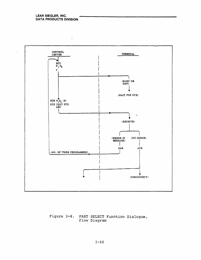
LEAR SIEGLER, INC. DATA PRODUCTS DIVISION
CONTROL CENTER TERMINAL
I r;!T I Nl~ I s
I I 1
(BUSY OR
I NOT)
L I I (WAIT FOR STX) ,
SOH N IN2 (10 I STX TEXT ETX LBC I l I II
I t I (RECEIVE)
I ~ I I (ERROR IN (NO ERROR)
MESSAGE)
I I I I jAK
ACK
(NO. OF TRIES PROGRAMMED) I I I
[ , (DISCONNECT)
Figure 3-8. FAST SELECT Function Dialogue, Flow Diagram
3-66

LEAR SIEGLER, INC. DATA PRODUCTS DIVISION
CONTROL CENTER ADDRESSED ADDRESSED
TERMINALS TERMINAL ~ I A THROUGH N-l I N
EOT I .. ',' =,
NIN2 I I t IA
I I I ( I I (B USY OR NOT) I (BUSY OR NOT) IB ~ I I I • • I :
(WAIT FOR STX)I (WAIT FOR STX)
1 ~ IN J I
SOH NIN2 (#) I STX TEXT ETX I
LRC I
L I • r I t
(RECEIVE) (RECEIVE)
1 I(ERR~R IN (NO ERROR) (DISCONNECT) I MESSAGE)
I I (NO. OF TRIES NAK ACK
: PROGRAMMED) )
1 I
.1
i • (DISCONNECT)
Figure 3-9. BROADCAST SELECT Function Dialogue, 'to" ,......'(.7 1"'\;.".,..... .... .".,.... .... .... \J.... ...., .... o.':::j ~ Q,U~
3-67

LEAR SIEGLER, INC. DATA PRODUCTS DIVISION
SEND Response (See figure 3-10.)
One of six characters specifies the informqtion that the addressed terminal is to send. The function character (v, w, x, y, z, or i) is transmitted in place of the "q" in the standard header. The six possible SEND functions are as follows:
1. Send Line Foreground (v). The terminal will send all foreground unprotected data in the line in which the cursor rests from beginning of line to the cursor position. NUL characters are not transmitted. The terminal marks each protected area in the line by sending an FS character.
2. Send Page Foreground (w). The terminal will send all foreground data in the page, starting at the HOME location and ending at cursor position. NUL characters are not transmitted. The terminal marks each protected area in the page by sending an FS character. Each end of line is indicated by US character.
3. Send Line All (x). The terminal will send all data, protected and unprotected, in the line in which the cursor rests and stops at cursor. All characters are transmitted, with the sequence [ESC )] preceding the first character of a protected field, and the sequence [ESC Q following the last character of a protected field.
4. Send Page All (y). The terminal will send all data, protected and unprotected, in the page, beginning at the HOME location and stops at cursor. All characters are transmitted, with the sequence [Esc )] preceding the first character of a protected field, . and the sequence[ESC (J following the last character of a protected field. ,
5. Send Message Foreground (z). The terminal will send all foreground data following an STX code and ending with an ETX code. NUL characters are not transmitted. The terminal marks each protected area within the STX/ETX brackets by sending an FS character. If no STX is on the screen, transmission starts at HOME. If no ETX is on the screen, transmission stops at last position on the screen.
3-68

LEAR SIEGLER, INC. DATA PRODUCTS DIVISION
CONTROL CENTER TERMINAL
I EOT A~ z, or (v,w,x.y, {) ENQ
I \.. •
Y I *SOH AIA2 (#)
STX TEXT ETX
LRC
4 j
r EOT NAK ACK
I I 1 '- • '\
EOT
( i (DISCONNECT)
(NO. OF TRIES PROGRAMMED)
*If header is needed (AWAITS POLLING)
Figure 3-10. SEND Function Dialogue, Flow Diagram
3-69

LEAR SIEGLER, INC. DATA PRODUCTS DIVISION
6. Send Message All ({). The terminal will send all data, protected and unprotected, between the STX/ETX codes. All characters are transmitted, with the sequence [ESC )] preceding the first character of a protected field, and the sequence [ESC (] after the last character of a protected field. If no STX is on the screen, transmission starts at HOME. If no ETX is on the screen, transmission stops at the last position on the screen.
The STX and ETX characters are entered on the screen by use of the SOM and EOM keys with and without shift, respectively.
In standard (ADM-2 compatible) operation, control codes maybe written by preceding the control code by ESC; i.e. (ESC Return) will cause the CR character to be written to the screen rather than being interpreted as a Return Operation.
3.10 SPECIAL POLLING OPERATIONS
In addition to acting as an ADM-2 compatible terminal, the ADM-42 , with the Polling Option installed, may perform in several special polling environments. These environments consist of GROUP POLL, GROUP SELECT, MULTI-POINT CONTENTION, and PRINTER SELECT operation. The paragraphs which follow describe these operations in terms of their differences from standard (ADM-2 compatible) polling operations.
3.10.1 GROUP POLL Operations
GROUP POLL is essentially the same as standard ADM-2 compatible POLL operations, except that the terminal address is the same for each terminal in the group. All terminals are daisychained via their EXTENSION/MODEM ports. Each terminal responds as would an individual terminal under standard POLL. The GROUP POLL address for each terminal on the line is set up using the two banks of DIP switches at locations 8L and 9L on the Option PCBA in the same manner as for standard POLL (using switch locations 5L and 6L). Keying "ESC'A" from the keyboard will display all Polling addresses.
3-70
LEAR SIEGLER, INC. DATA PRODUCTS DIVISION
3.10.2 GROUP SELECT Operations
GROUP SELECT is essentially the same as standard ADM-2 compatible BROADCAST SELECT operations, except that the GROUP SELECT address (Ga ) is inserted in the header in place of the "t". The complete address thus becomes: "EOT NIN2 Ga SOH NlN2 (#) STX TEXT ETX LRC". (Ga is an upper case alpha character, a to z.) Also:
1. The GROUP SELECT address requires only one bank of DIP switches, at location IlL on the Option PCBA, to be established.
2. Several groups may be selected by means of different terminal addresses. Every terminal in a group must be on the same line, but the line does not have physical limitations.
3. All terminals on line will connect unconditionally, with the addressed terminal responding as specified for BROADCAST SELECT.
3.10.3 MULTI~POINT CONTENTION Operations
MULTI-POINT CONTENTION is a polling mode which is selectable only by the control center, using the following control characters: "EOT NULL NULL BEL". In this mode, the control center CPU notifies all terminals (on the line that the CPU will not poll until it has a message to be sent or until a polling terminal signifies that it has a message for the CPU. 3.10.4 Addressable Printer Port Operations
The Addressable Printer Port operations are used to enable the ADM-42 to receive CPU output messages at the selected transmission rate, store the message, and retransmit the message in the prescribed format to a printer. The operation is as follows:
1. With the ADM-42 set up for standard polling, the control center calls for SELECT, as follows: "EOT AIA3 q ENQ". Note that the second terminal address (A2) is incremented to A3; this causes the ADM-42 to enable the print buffer (highest page) for operation. ~ buffer-not-empty condition will cause a terminal BUSY response.
3-71

LEAR SIEGLER, INC. DATA PRODUCTS DIVISION
2. The terminal responds to SELECT in the same manner as described in paragraph 3.9.5. Also a NAK may be sent upon completion of a message not only because of an incorrect LRC, or terminal BUSY; a printer buffer overflow will also cause the entire mes sage to fiNAl< II •
3. Once the terminal responds to the message with an "ACK" the ADM-42 disconnects, returns to the polling IDLE state, and begins outputting to the printer. Printing proceeds at the baud rate determined by the PRINTER BAUD RATE switch on the front panel, and continues until the buffer is empty. The terminal operates in Serial Buffered Print Mode (refer to paragraph 3.9.9) unless an "ESC [ (*)] II sequence has established a different print mode (as determined by the *).
4. Once printing from the buffer begins, no further messages from the control center may be received by the print buffer until the buffer is empty. (The terminal responds BUSY only to a print message.)
3-72
3.8.5
LEAR SIEGLER, INC. DATA PRODUCTS DIVISION
• ESC. [F (HEX)} " establishes which visual attributes will be applied to the message which will be placed on Status Line 25 in response to an "ESC F" command (refer to paragraph 3.8.5). The two-character HEX character establishes the same video attributes described in paragraph 3.8.10, in accordance with the following:
FOO Corresponds to ESC GO.
FOl Corresponds to ESC Gl.
F02 Corresponds to ESC G2.
F03 Corresponds to ESC G3.
F04 Corresponds to ESC G4.
F05 Corresponds to ESC G5.
F06 Corresponds to ESC G6.
F07 Corresponds to ESC G7.
Terminal/Mode Control Operations
Remote Keyboard Control
The ADM-42 keyboard can be disabled locally or disabled by a remote computer using the ASCII code associated with the following keystrokes:
ESC # Disables all keyboard operations.
ESC" Enables keyboard and restores keyboard control.
Disabling the keyboard (ESC #) protects the keyboard against inadvertent operation. "LOCK" is displayed in Status Line 25. Keyboard operation can be restored manually by pressing SHIFT/RESET momentarily.
ADM-l Mode Control
Upon occasion it may be required that the ADM-42 operate were an ADM-I for certain transmissions. The ADM-I Mode entered by executing "ESC %" and terminated by executing When in effect, "ADM-I" is displayed in Status Line 25. following changes are affected in ADM-42 transmission.
• The FS code is not transmitted between fields.
as if it is "ESC $". The
• The NEW LINE (US) code is not transmitted at the end of each line.
• The cursor goes to the first unprotected field on the screen when PROT MODE is set.
3-46
LEAR SIEGLER, INC. DATA PRODUCTS DIVISION
APPENDIX A OPERATOR'S QUICK REFERENCE GUIDES

LEAR SIEGLER, INC. DATA PRODUCTS DIVISION
OPERATOR'S QUICK REFERENCE GUIDE TO BAUD RATE CHANGE
Keys Used: ESC: [ASCII Character]
MODEM PORT . ASYNC PRNTR PORT
SWITCH BAUD (KEYBOARD (REMOTE) POSITION RATE ASCII HEX CODE ASCII HEX CODE
0 50 @ 40 -- --I 75 A 41 a 61 2 110 B 42 b 62
3 134.5 C 43 c 63 4 150 D 44 d 64
I 5 300 E 45 e 65
6 600 F 46 f 66 7 1200 G 47 g 67 8 1800 H 48 h 68
9 2000 I 49 i 69 10 2400 J 4A j 6A 11 3600 K 4B k 6B
12 4800 L 4C 1 6C 13 7200 M 40 m 6D 14 9600 N 4E n 6E
A-I
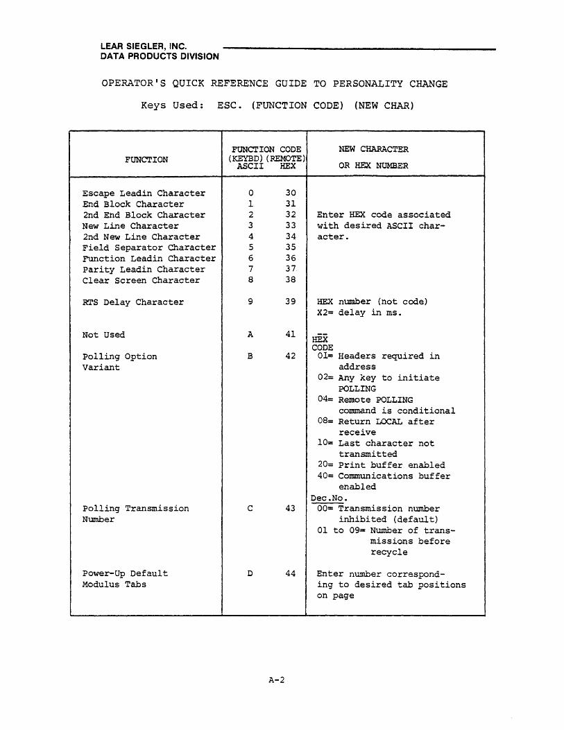
LEAR SIEGLER, INC. DATA PRODUCTS DIVISION
OPERATOR'S QUICK REFERENCE GUIDE TO PERSONALITY CHANGE
Keys Used: ESC. (FUNCTION CODE) (NEW CHAR)
FUNCTION
Escape Leadin Character End Block Character 2nd Ehd Block Character New Line Character 2nd New Line Character Field Separator Character Function Leadin Character Parity Leadin Character Clear Screen Character
RTS Delay Character
Not Used
polling Option Variant
Polling Transmission Number
Power-Up Default Modulus Tabs
FUNCTION CODE (KEYED) (REMOTE)
ASCII HEX
a 30 1 31 2 32 3 33 4 34 5 35 6 36 7 37 8 38
9 39
A 41
B 42
C 43
D 44
A-2
NEW CHARACTER
OR HEX NUMBER
Enter HEX code associated with desired ASCII character.
HEX number (not code) X2= delay in ms.
HEX CODE
01= Headers required in address
02= Any key to initiate POLLING
04= Remote POLLING command is conditional
08= Return LOCAL after receive
10= Last character not transmitted
20= Print buffer enabled 40= Communications buffer
enabled Dec.No.
00= Transmission number inhibited (default)
01 to 09= Number of transmissions before recycle
Enter number correspond-ing to desired tab positions on page
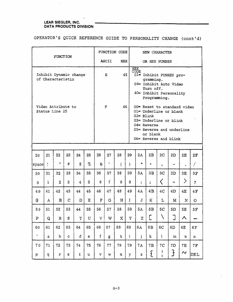
LEAR SIEGLER, INC. DATA PRODUCTS DIVISION
OPERATOR'S QUICK REFERENCE GUIDE TO PERSONALITY CHANGE (cont'd)
FUNCTION CODE NEW CHARACTER FUNCTION
ASCII HEX OR HEX NUMBER
HEX CODE
Inhibit Dynamic change E 45 01= Inhibit FUNKEY pro-of Characteristic gramming.
04= Inhibit Auto Video Turn off.
40= Inhibit Personality Programming.
Video Attribute to F 46 00= Reset to standard video Status Line 25 01= Underline or blank
02= Blink 03= Underline or blink
I . 04= Reverse 05= Reverse and underline
or blank 06= Reverse and blink
.
20 21 22 23 24 25 26 27 28 29 2A 2B 2C 2D 2E 2F
'space ! " :#= $ % & I ( \ * + - / I j
30 31 32 33 34 35 36 37 38 39 3A 3B 3C 3D 3E 3F
0 1 2 3 4 5 6 7 8 9 : ; < = > ?
40 41 42 43 44 45 46 47 48 49 4A 4B 4C 4D 4E 4F
@ A B C ·D E F G H I J K L M N 0
50 51 52 53 44 55 56 57 58 59 5A 5B 5C 5D 5E 5F
p Q R S T U V W X y Z [ \ ] /\ -60 61 62 63 64 65 66 67 68 69 6A 6B 6C 6D 6E 6F
, a b c d e f g h i j k 1 m n 0
70 71 72 73 74 75 76 77 78 79 7A 7B 7C 7D 7E 7F
t I } N P q r s t u v w x y z , DEL
A-3

LEAR SIEGLER, INC. DATA PRODUCTS DIVISION
OPERATOR'S QUICK REFERENCE GUIDE TO
VIDEO ATTRIBUTE CONTROL SEQUENCE
FUNCTION
RESET TO STANDARD VIDEO
UNDERLINING OR BLANKING OF DESIGNATED AREA
BLINKING OF DESIGNATED AREA
UNDERLINING OR BLINKING OF DESIGNATED AREA
REVERSING OF DESIGNATED AREA
REVERSING AND UNDERLINING OR BLfu~KING OF DESIGNATED AREA
REVERSING AND BLINKING OF DESIGNATED AREA
REVERSING AND UNDERLINING OR BLINKING OF DESIGNATED AREA
BLINKING OF DATA IN FIELD BRACKETED BY DELIMITER
BLANKING OF DATA IN FIELD BRACKETED BY DELIMITER
VIDEO OFF
RESTORE VIDEO; CURSOR OFF
RESTORE VIDEO; CURSOR STEADY
RESTORE VIDEO; CURSOR BLINK
ESCAPE CODE
ESC GO
ESC Gl
ESC G2
ESC G3
ESC G4
ESC GS
ESC G6
ESC G7
ESC 1\
ESC -
ESC I1J 0
ESC f'u 1
ESC ru 2
ESC ru 3
.-.. ----------~--------
A-4

LEAR SIEGLER, INC. DATA PRODUCTS DIVISION
OPERATOR'S QUICK REFERENCE GUIDE TO CTRL KEY SEQUENCE
Keys Used: CTRL/(ASCII Character)
FUNCTION GRAPHIC CHARACTER SET
HEX 0 1 2 3 4 5 6 7
LSBs MSBs 4321 765
000 001 100 101
0 0000 NUL DLE @ P
1 0001 SOH DCI A Q
2 0010 STX DC2 B R
3 0011 ETX DC3 C S
4 0100 EOT DC4 D T
5 0101 ENQ NAK E U
6 0110 ACK SYN F V
7 0111 BEEP ETB G W
8 1000 ( ..... )
BS CAN H X (SKIP)
9 1001 HT EM I Y
A 1010 LF ( , ) SUB J Z
B 1011 VT ( . ) ESC K [
C 1100 FF ( .... ) FS L \
D 1101 CR GS M J
E 1110 SO (HOME) N 1\ RS
F 1111 SI (NEW 0 -T, TNR) DR
A-S

LEAR SIEGLER, INC. DATA PRODUCTS DIVISION
OPERATOR'S QUICK REFERENCE GUIDE
TO GRAPHIC CHARACTER SET CODES
FUNCTION GRAPHIC CHARACTER SET
HEX a 1 2 3 4 5 6 7
LSBs MSBs 4321 765 000 001 010 all 100 101 110 III
a 0000 NUL DLE a @ P P
1 0001 SOH DC1 ! 1 A Q a q
2 0010 STX DC2 " 2 B R b r
3 0011 ETX DC3 # 3 C S c s
4 0100 EOT DC4 $ 4 D T d t
5 0101 ENQ NAK % 5 E U e u
6 0110 ACK SYN & 6 F V f v
7 0111 BEEP ETB , 7 G W g w
( ... )
8 1000 BS CAN ( 8 H X h x (SKIP)
9 1001 HT EM ) 9 I Y i v
A 1010 LF ( t ) SUB * : J Z j z
B 1011 VT ( . ) ESC + ; K [ k f
< j
C 1100 FF ( .. ) FS , L \ 1 •
D 1101 CR GS - = M ] m ~ (HOME)
E 1110 SO RS . > N A n "V
F 1111 SI (NEW LINE) US / ? 0 - 0 DEL
A-6

LEAR SIEGLER, INC. DATA PRODUCTS DIVISION
OPERATOR'S QUICK REFERENCE GUIDE TO ESCAPE SEQUENCE
Keys Used: ESC/SHIFT!{ASCII Character) or ESC/(ASCII Character)
ESCAPE SEQUENCE
HEX 2 3 4 5 6 7
.-9J CLEAR TABS ~ PRINT PROT W PRINT PAGE .-:.J POLLING ~ PRINT 0 AS SPACES* ALL I ADDRESS* (UNF)
1 L.U PROG uJ SET TAB ~ ~CHAR l..LJ AUX ~ INSERT
FNCTN* INSERT CONTROL * MODE ON
!! I ENABLE i-Ll CLEAR TAB .~ SET BLOCK WLJ LIr~E ~ STA·~·US ~INSERT . I
2 i----i KEYBD DELETE 1 OFF MODE OFF
3 WJ DISABLE KEYBD
I-Ll SET TAB MODE*
~ SET CONV ~SEND ~ STATUS ~SEND MSG FG 1 ON MSG ALL
4 W-J CLEAR ~ SEND ~ DUPLEX ~LINE ~ STATUS ~LINE
ADMl M LINE FG CONTROL * ERASE SP 2 OFF ERASE NUT,
5 WSET ~SEND W LINE WLJ PROGM ~ STATUS ~ PROGM
ADMl M PAGE FJi INSERT ..MOD.E. SET 2 ON ~DE ("T.~
b -!J SET .-U SEND ~ MESSAGE I-YJ SET PROT ~ STATUS ~ AUTO PAGE
PROTECT LINE ALL TO ROW 25* COL OF SP 3 OFF ON
7 ~ RESET LzJ SEND ~ ATTRIBUTE ~CHAR ~ STATUS ~ AUTO PAGE
PROTECT PAGE ALL CONTROL * DELETE 3 ON OFF
8 ~ CLEAR
WPROT WJ WRITE
SOM (STX) W WLJ PROGM
MODE CLR ~ ~
~SET 9 I WRITE 12J BACKTAB ~ ERASE W:-J SKIP ~PAGE 9 WPROT !-.;:.J (ETX) EOM PAGE SP (TAB) ERASE NUL
~ CLR ALL ~ CLR FG -Ll PAGE .-U MODES ..u f-..U A TO NUL NUL BACK CLEAR
B ~ CLR ALL ~ CLR FG -K.J PAGE -1J PRINT ~ ~
• TO SPACE SPACE FWD CONTROL * ~ CLR-ALL ~ STATUS ~ GO TO PAGE ~ ENVOKE W:-J W-J CHANGE
C TO PROT SP 4 ON N (1-8)* FUNCTION* BAUD RATE*
D ~'LOAD PG L.;:J LOAD !JLJ MOLT WJ ~ WRITE WJ & CURS CURSOR ESC* MULT CHAR*
E W PROGRAM ~ STATUS W!J SET PAGE ~ BLINK ~ ~.VIDEO &
PERSONALITY* 4 OFF EDIT CONT'ROT I CURSOR IN·X
F ~ SEND PG ~ SEND ~ RESET l=J BLANK ~ DISPLAY ~ & CURS CURSOR PAGE EDIT CONTROL OE'RSONALITY
*Requires additional characters to complete sequence
A-7

LEAR SIEGLER, INC. DATA PRODUCTS DIVISION
X or Y ~OSITION
1 2 3 4 5 6 7 8 9
10 11 12 13 14 15 16 17 18 19 20 21 22 23 24 25 26 27 28 29 30 31 32 33 34 35 36 37 38 39 40
OPERATOR'S QUICK REFERENCE GUIDE TO ABSOLUTE CURSOR POSITIONING SEQUENCE
AND MODULO NUMBERS
MODULO ASCII HEX X or Y MODULO NUMBER CODE CODE POSITION NUMBER
0 SPACE 20 41 40 1 ! 21 42 41 2 " 22 43 42 3 # 23 44 43 4 $ 24 45 44 5 % 25 46 45 6 & 26 47 46 7 I 27 48 47 8 ( 28 49 48 9 ) 29 50 49
10 * 2A 51 50 11 + 2B 52 51 12 , 2C 53 52 13 - 20 54 53 14 . 2E 55 54 15 / 2F 56 55 16 0 30 57 56 17 1 31 58 57 18
I 2 32 59 58
19 3 33 60 59 20 4 34 61 60 21 5 35 62 61 22 6 36 63 62 23 7 37 64 63 24 8 38 65 64 25 9 39 66 65 26 : 3A 67 66 27 ; 3B 68 67 28 < 3C 69 68 29 = 3D 70 69 30 > 3E 71 70 31 ? 3F 72 71 32 @ 40 73 72 33 A 41 74 73 34 B 42 75 74 35 C 43 76 75 36 0 44 77 76 37 E 45 78 77 38 F· 46 79 78 39 G 47 80 79
A-8
ASCII HEX CODE CODE
H 48 I 49 J 4A K 4B L 4C M 40 N 4E a 4F P 50 Q 51 R 52 S 53 T 54 U 55 V 56 W 57 X 58 y 59 Z SA [ 5B \ 5C ] 50 t\ 5E - SF ,
60 a 61 b 62 c 63 d 64 e 65 f 66 g 67 h 68 i 69 j 6A k 6B 1- 6C m 60 n 6E 0 6F
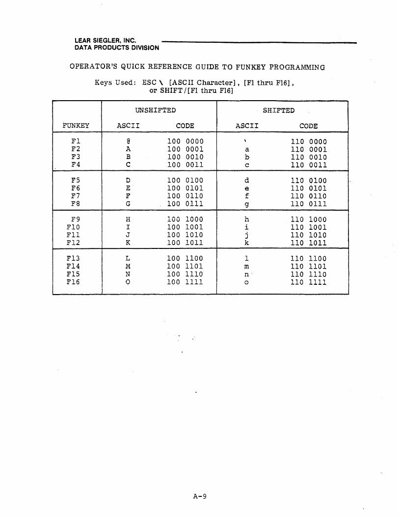
.
LEAR SIEGLER, INC. DATA PRODUCTS DIVISION
OPERATOR'S QUICK REFERENCE GUIDE TO FUNKEY PROGRAMMING
FUNKEY
Fl F2 F3 F4
FS F6 F7 F8
F9 FlO Fll F12
F13 F14 FlS F1
Keys Used: ESC \ [ASCII Character], [FI thru FI6] 9
or SHIFT / [FI thru FI6]
UNSHIFTED SHIFTED
ASCII CODE ASCII CODE
@ 100 0000 \ 110 0000 A 100 0001 a 110 0001 B 100 0010 b 110 0010 C 100 0011 c 110 0011
D 100 0100 ~ 110 0100 u.
E 100 0101 e 110 0101 F 100 0110 f 110 0110 G 100 0111 g 110 0111
H 100 1000 1 h 110 1000 I 100 1001 i 110 1001 J 100 1010 j 110 1010 K 100 1011 k 110 1011
L 100 1100 1 110 1100 M 100 1101 m 110 1101 N 100 1110 n' 110 1110 o , , , .... 00 ........ 11 o , , , 110 1.J...J...J..
A-9
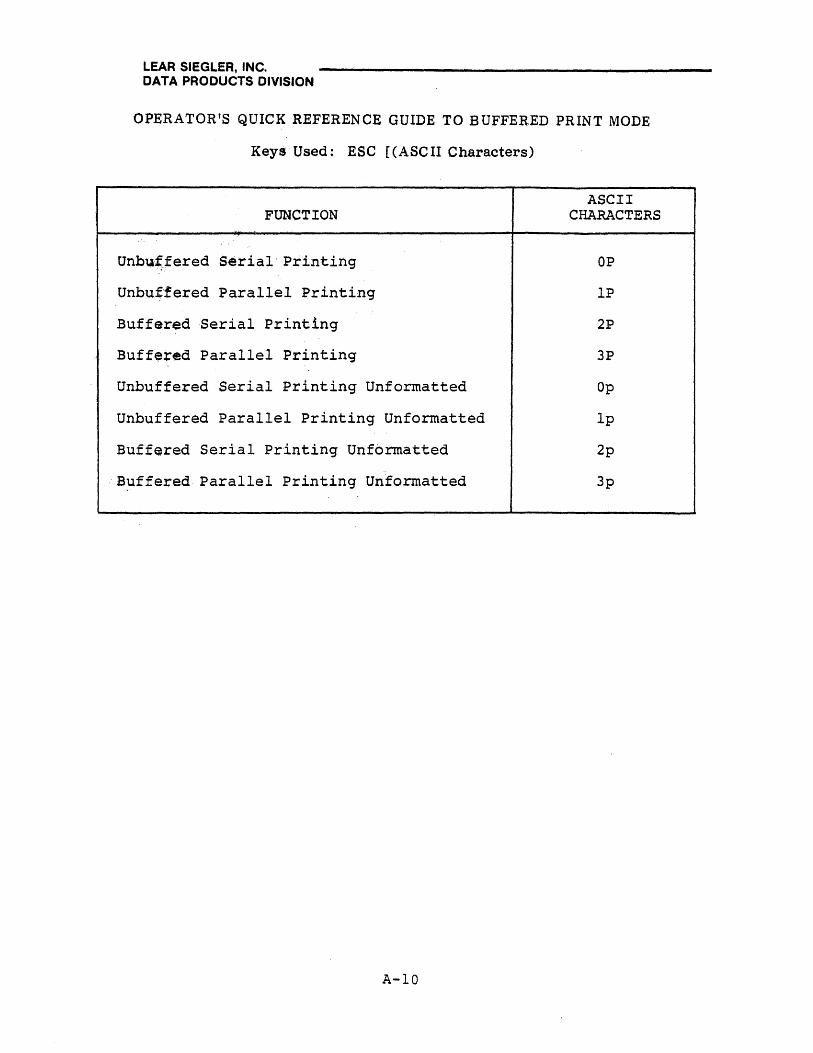
LEAR SIEGLER, INC. DATA PRODUCTS DIVISION
OPERATOR'S QUICK REFERENCE GUIDE TO BUFFERED PRINT MODE
Keys Used: ESC [(ASe II Characters)
FUNCTION
Unbuf.fered Serial· Printing
Unbuffered Parallel Printing
Buffered Serial Printing
Buffered Parallel Printing
Unbuffered Serial Printing Unformatted
Unbuffered Parallel Printing Unformatted
Buffered Serial Printing Unformatted
·Buffered Parallel Printing Unformatted
A-IO
ASCII CHARACTERS
OP
IP
2P
3P
Op
lp
2p
3p