user’s manual yvp management software valvenavi · foundation fieldbus overview ... 6-1 6.2...
TRANSCRIPT

User’sManual
Yokogawa Electric Corporation
IM 21B04C50-01E
YVP Management SoftwareValveNavi
IM 21B04C50-01E5th Edition
Toc-1<Int> <Ind> <Rev>
IM 21B04C50-01E
CONTENTS
IM 21B04C50-01E 5th Edition
YVP Management softwareValveNavi
Media No. IM 21B04C50-01E 5th Edition : Sep. 2009 (YK)All Rights Reserved Copyright © 2001, Yokogawa Electric Corporation
1. INTRODUCTION ...................................................................................... 1-11.1 About This Manual .......................................................................................... 1-1
1.2 Software License Agreement ......................................................................... 1-2
1.3 About This Software ....................................................................................... 1-3
1.4 Important Safety Warnings ............................................................................. 1-3
1.5 Trademarks, Copyrights, and Patents ............................................................ 1-4
2. INTRODUCTION TO ValveNavi ................................................................ 2-12.1 What is ValveNavi? .......................................................................................... 2-1
2.2 ValveNavi Specifications ................................................................................ 2-1
2.3 Combination of ValveNavi & YVP ................................................................... 2-1
2.4 What is FOUNDATION® Fieldbus? ................................................................. 2-2
2.4.1 Guide to a successful Foundation fieldbus installation ....................... 2-3
3. INSTALLATION OF HARDWARE AND SOFTWARE ............................... 3-13.1 What you need to get started with ValveNavi ................................................ 3-1
3.2 Reference Model Process ............................................................................... 3-2
3.2.1 Wiring requirements ......................................................................... 3-3
3.3 Installing NI-FBUS........................................................................................... 3-4
3.3.1 Configure the NI-FBUS interface card safely for different tasks ......... 3-4
3.3.2 Installing the Device Descripfions (DD) with NI-FBUS InterfaceConfiguration Utility ........................................................................... 3-6
3.3.3 Location of DD files and .DCT file ..................................................... 3-7
4. ValveNavi ADMINISTRATION ................................................................. 4-14.1 Hardware and Software Requirements .......................................................... 4-1
4.2 Installing ValveNavi ......................................................................................... 4-1
4.3 Trial Period ...................................................................................................... 4-2
4.4 Licensed User Process ................................................................................... 4-3
4.5 Logging on with Registration ......................................................................... 4-4
4.6 Setting Up User Accounts .............................................................................. 4-5
4.6.1 System Administration, Passwords, and Privilege Levels ................. 4-5
4.6.2 Start the Administration Program ...................................................... 4-5
4.6.3 Privilege Levels ................................................................................. 4-6
4.7 Finish ValveNavi .............................................................................................. 4-8

<Int> <Ind> <Rev>
IM 21B04C50-01E
Toc-2
5. FOUNDATION FIELDBUS OVERVIEW .................................................... 5-15.1 Reference Model Process Used in This User’s Manual ................................. 5-1
5.1.1 P & I D .............................................................................................. 5-2
5.1.2 Function block links........................................................................... 5-3
5.2 Device Operational States and Block Modes ................................................ 5-5
5.3 Block Modes .................................................................................................... 5-7
5.4 Examples of IVI Operational States ............................................................... 5-9
5.5 Changing Operational States ....................................................................... 5-12
6. QUICK TOUR OF ValveNavi .................................................................... 6-16.1 Introduction ..................................................................................................... 6-1
6.2 Fieldbus Device Tree ....................................................................................... 6-2
6.3 Menu Bar and Tool Bar .................................................................................... 6-3
6.3.1 Menu items ....................................................................................... 6-3
6.3.2 Toolbar icons .................................................................................... 6-3
6.4 Control Valve Faceplate .................................................................................. 6-4
6.5 Companion Device Display Frame ................................................................. 6-5
6.6 Status Frame ................................................................................................... 6-5
6.7 Accessing Services in ValveNavi ................................................................... 6-6
6.8 Setup Wizard ................................................................................................... 6-7
6.8.1 Actuator Wizard ................................................................................ 6-8
6.8.2 Tuning Wizard ................................................................................... 6-9
6.8.3 Travel Calibration Wizard ................................................................ 6-10
6.8.4 Position Control Limits - Wizard....................................................... 6-11
6.8.5 Finish - Setup Wizard ...................................................................... 6-12
6.9 Configuration Services ................................................................................. 6-13
6.10 Calibration Services ..................................................................................... 6-14
6.11 Diagnostic Services ...................................................................................... 6-15
6.12 Operation State ............................................................................................. 6-16
6.13 Device Query ................................................................................................. 6-17
6.14 PID Control Dialog ........................................................................................ 6-18
6.15 Rescan ........................................................................................................... 6-19
6.16 About ............................................................................................................. 6-19
6.17 Online Help .................................................................................................... 6-20
7. INTEGRATED VALVE INTERFACE (IVI) ................................................... 7-17.1 Device Selection ............................................................................................. 7-3
7.1.1 The Pop-Up Menu In Device Selection .............................................. 7-4
7.1.2 Setting Device as LM or Basic Device ............................................... 7-5
7.2 Control Valve Faceplate .................................................................................. 7-6
7.2.1 Selected Device ................................................................................ 7-6
7.2.2 Block Actual Mode ............................................................................ 7-7
7.2.3 Position ............................................................................................. 7-7

Toc-3<Int> <Ind> <Rev>
IM 21B04C50-01E
7.2.4 Other Status ..................................................................................... 7-7
7.2.5 Temperature, Pressure, and I/P Graphs ............................................ 7-8
7.3 Companion Device .......................................................................................... 7-8
8. SETUP WIZARD ...................................................................................... 8-18.1 Introduction to Setup Wizard .......................................................................... 8-1
8.2 Actuator Wizard ............................................................................................... 8-2
8.3 Tuning Wizard .................................................................................................. 8-3
8.4 Travel Calibration Wizard ................................................................................ 8-5
8.5 Position Control limits Wizard ........................................................................ 8-6
8.6 Finish-Setup Wizard ........................................................................................ 8-8
9. CONFIGURATION SERVICES ................................................................. 9-19.1 Configuration - General .................................................................................. 9-1
9.1.1 Device Info ........................................................................................ 9-2
9.1.2 Block Tag Info ................................................................................... 9-3
9.1.3 Others Installed ................................................................................ 9-3
9.2 Configuration - Position ................................................................................. 9-4
9.2.1 Servo Parameters ............................................................................. 9-4
9.2.2 Position Limit .................................................................................... 9-5
9.2.3 Limit Switch Threshold ...................................................................... 9-6
9.2.4 Fault Control ..................................................................................... 9-6
9.2.5 Servo Alarms (I/P Module Operating Point Fault Control) .................. 9-6
9.2.6 Advanced ......................................................................................... 9-7
9.2.7 Configuration - Advanced Position .................................................... 9-7
9.3 Configuration - Actuator ................................................................................. 9-8
9.3.1 Valve Action ...................................................................................... 9-8
9.3.2 Actuator Type .................................................................................... 9-8
9.3.3 Relay Type ........................................................................................ 9-9
9.3.4 Valve Type ........................................................................................ 9-9
9.3.5 Continuous Data Limit ....................................................................... 9-9
9.3.6 Model And Serial Number of Valve ................................................. 9-10
9.4 Configuration - AO Block.............................................................................. 9-11
9.4.1 Limits .............................................................................................. 9-11
9.4.2 Configuration - AO Block Options .................................................... 9-12
9.5 Configuration - PID Block ............................................................................. 9-13
9.5.1 PID Parameters .............................................................................. 9-13
9.5.2 Limits .............................................................................................. 9-14
9.5.3 PV Scale......................................................................................... 9-15
9.5.4 Configuration - PID Options ............................................................ 9-15
9.6 Configuration - Options ................................................................................ 9-17
9.6.1 Characterization Frame .................................................................. 9-17
9.6.2 Pressure Frame .............................................................................. 9-21
9.6.3 Others Frame ................................................................................. 9-21

<Int> <Ind> <Rev>
IM 21B04C50-01E
Toc-4
10. CALIBRATION SERVICES .................................................................... 10-110.1 Calibration - Range ....................................................................................... 10-1
10.1.1 Find Range Result .......................................................................... 10-2
10.1.2 GO ................................................................................................. 10-2
10.1.3 Auto Stop Limits .............................................................................. 10-2
10.1.4 Manual Stop Limits ......................................................................... 10-3
10.2 Calibration - Tuning ....................................................................................... 10-4
10.2.1 Auto Tune ....................................................................................... 10-5
10.2.2 Auto Tune Result ............................................................................. 10-6
10.2.3 Search Stops and Auto Tune In One Step ....................................... 10-6
10.2.4 Manual parameter adjustment ........................................................ 10-7
10.3 Travel Calibration .......................................................................................... 10-8
10.3.1 Calibration Result ......................................................................... 10-10
10.3.2 Apply Calib ................................................................................... 10-10
10.3.3 Pick Target Position for Calibration ............................................... 10-10
10.4 Calibration - Advanced Position Servo Tuning Parameters ...................... 10-11
11. PID BLOCK SERVICES ......................................................................... 11-111.1 States and Modes ......................................................................................... 11-2
11.2 Tuning Parameters ........................................................................................ 11-3
11.3 Simulation Function...................................................................................... 11-4
11.3.1 Simulation State ............................................................................. 11-4
12. TRENDING SERVICE ............................................................................ 12-112.1 Trend Selection ............................................................................................. 12-3
12.2 Scope Settings .............................................................................................. 12-4
12.3 Saving and Opening Trend Files .................................................................. 12-5
12.4 Changing Valve Position while Trending ...................................................... 12-6
12.5 Closing the Trend Service ............................................................................. 12-6
13. SAVING, DOWNLOADING, AND CLONING A CONFIGURATION ......... 13-113.1 Open File ....................................................................................................... 13-1
13.2 Save to File .................................................................................................... 13-2
13.3 Download ...................................................................................................... 13-3
13.4 Copy a Configuration to a New Positioner .................................................. 13-5
14. DIAGNOSTIC SERVICES ...................................................................... 14-114.1 General .......................................................................................................... 14-1
14.2 Self Check ..................................................................................................... 14-3
14.3 Signature ....................................................................................................... 14-5
14.3.1 Actuator Signature .......................................................................... 14-6
14.3.2 Extended Actuator Signature .......................................................... 14-9
14.3.3 High Resolution Actuator Signature .............................................. 14-11
14.3.4 Step Response Test ...................................................................... 14-11
14.3.5 Positioner Signature ..................................................................... 14-20
Toc-5<Int> <Ind> <Rev>
IM 21B04C50-01E
14.3.6 Signature Selection ...................................................................... 14-22
14.3.7 Signature Setting .......................................................................... 14-23
14.3.8 Signature Measurement ............................................................... 14-24
14.3.9 Signature Graphs ......................................................................... 14-25
14.3.10 Graph Scale Setup ....................................................................... 14-27
14.3.11 Signature Summary ...................................................................... 14-28
14.3.12 Signature Notes ............................................................................ 14-29
15. QUERY SERVICES ................................................................................ 15-1
16. REPORTING SERVICES ....................................................................... 16-116.1 Configuration Report .................................................................................... 16-1
16.2 Communication Error Log ............................................................................ 16-2
17. FAILSAFE HANDLING .......................................................................... 17-117.1 Introduction ................................................................................................... 17-1
17.2 Failsafe Active Latched ................................................................................ 17-1
17.3 Failsafe Clear Latched .................................................................................. 17-2
17.4 Failsafe Clear Non-Latch .............................................................................. 17-2
17.5 To Exit Failsafe .............................................................................................. 17-3
17.5.1 If the Deviation Error Failsafe is set ................................................. 17-3
17.5.2 If the failsafe is caused by internal diagnostics ................................ 17-8
APPENDICES ............................................................................................... App-1Appendix A Glossary and Acronyms ..................................................................... App-1
Appendix B Configuring DI Blocks to TB Channels .............................................. App-6
Appendix C Setting a Failsafe Strategy.................................................................. App-7
REVISION RECORD

Blank Page

1-1
IM 21B04C50-01E
<Toc> <Ind> <1. INTRODUCTION>
1. INTRODUCTIONThis User’s Manual gives instructions on handling of YVP Management Software“ValveNavi”(Model: YVP20S).
This software is to be used to setup the YVP110 advanced valve positioner;therefore, it is indispensable for users to read, understand and follow theinstructions on the YVP110 user’s manual (IM 21B04C01-01E) BEFORE actuallystarting the operation.
It is also highly recommended to become well-informed about Foundation FieldbusCommunication by reading the materials as follows.
Referential materials issued by Yokogawa Electric Corp.
TI 38K02A01-01E Fieldbus Book - A Tutorial
TI 38K03A01-01E Fieldbus Technical Information
For the continuous usage of the software, the registration is required. Please readthe corresponding part in this manual and complete the necessary procedures.
1.1 About This Manual• This manual should be delivered to the end user.
• The information contained in this manual is subject to change without prior notice.
• The information contained in this manual, in whole or part, shall not be transcribed orcopied without YOKOGAWA’s written permission.
• In no case does this manual guarantee the merchantability of the positioner or thesoftware or its adaptability to a specific client needs.
• Should any doubt or error be found in this manual, submit inquiries to your localdealer.
• Changes to specifications, structure, and components used may not lead to therevision of this manual unless such changes affect the function and performance ofthe products.

1-2<Toc> <Ind> <1. INTRODUCTION>
IM 21B04C50-01E
1.2 Software License AgreementFollowing is the software License Agreement which should be agreed by users before startusing the software. The agreement will be shown when you install the software.
Yokogawa Electric Corporation Software License Agreement
This is a legal agreement between you and Yokogawa Electric Corporation. By selectingAccept or by using the software, you agree to be bound by the terms of this agreement. Ifyou do not agree to the terms of this agreement, select Not Accept.
1. Grant of License: This License Agreement permits you (Licensee) to use one copy of thespecified version of the software identified above (Software) on any single computer.
2. Copyright: The Software is owned by Yokogawa Electric Corporation (Licensor) and itssuppliers and is protected by Japan copyright laws and international treaty provisions.Therefore, Licensee must treat the Software like any other copyrighted material except thatLicensee may either (a) make one copy of the Software solely for backup or archival pur-poses, or (b) transfer the Software to a single hard disk provided Licensee keeps theoriginal solely for backup or archival purposes. Licensee may not reverse engineer,decompile or disassemble the Software.
3. Limited Warranty: Licensor warrants that the Software will perform substantially inaccordance with the accompanying printed materials for a period of ninety (90) days fromthe date of receipt. If the Software contains any material errors, malfunctions, or defects,Licensor shall exert a good faith effort either to correct or replace the Software, at theelection of Licensor, which remedy shall be the exclusive remedy of Licensee for sucherrors, malfunctions or defects. If a reasonable amount of effort of Licensor or its supplierwill not correct the error, then Licensor will have no further obligation to remedy such errors,malfunctions or defects.
LICENSOR MAKES NO OTHER REPRESENTATIONS OR WARRANTIES, EXPRESS ORIMPLIED, INCLUDING THE WARRANTY OF MERCHANTABILITY AND FITNESS FOR APARTICULAR PURPOSE, WITH RESPECT TO THE SOFTWARE AND ASSOCIATEDDOCUMENTATION.
IN NO EVENT SHALL LICENSOR BE LIABLE TO LICENSEE FOR INDIRECT, SPECIALINCIDENTAL OR CONSEQUENTIAL DAMAGES (WHETHER DENOMINATED IN CON-TRACT, TORT, STRICT LIABILITY IN TORT, NEGLIGENCE OR OTHER THEORIES) ORFOR LOST PROFITS OR INCREASED EXPENSES ARISING OUT OF THIS AGREE-MENT OR THE USE OF THE SOFTWARE AND ASSOCIATED DOCUMENTATION.
IN NO EVENT SHALL THE TOTAL LIABILITY OF LICENSOR FOR DAMAGES TO LIC-ENSEE EXCEED THE SUM PAID BY LICENSEE TO LICENSOR FOR THE SOFTWAREAND ASSOCIATED DOCUMENTATION.
1-3
IM 21B04C50-01E
<Toc> <Ind> <1. INTRODUCTION>
1.3 About This SoftwareThis software is intended for use only with Yokogawa YVP positioners. The positioners areintended for use with industrial compressed air systems only. Ensure that an adequatepressure relief provision is installed if application of system supply pressure could causedownstream equipment to malfunction. Installation should be in accordance with local andnational compressed air and instrumentation codes.
Positioners certified for use in explosionproof/flameproof or intrinsically safe installationsMUST:
a) Be installed in accordance with local and national codes for hazardous areainstallations;
b) Be maintained only by qualified personnel with adequate training on hazardous areainstrumentation; and
c) Be maintained only by qualified personnel with adequate training in the use ofFoundation fieldbus.
This software is not intended for use in life support systems. This software is not intendedfor use in safety shutdown systems. Substitution of positioner parts and components maylead to unsafe operation or compromise performance.
Items sold by Yokogawa Electric Corp. are warranted to be free from defects in materialsand workmanship for a period of one year from the date of shipment, provided said itemsare used according to Yokogawa’s recommended usages.
Yokogawa reserves the right to discontinue manufacture of any product or change productmaterials, design, or specifications without notice.
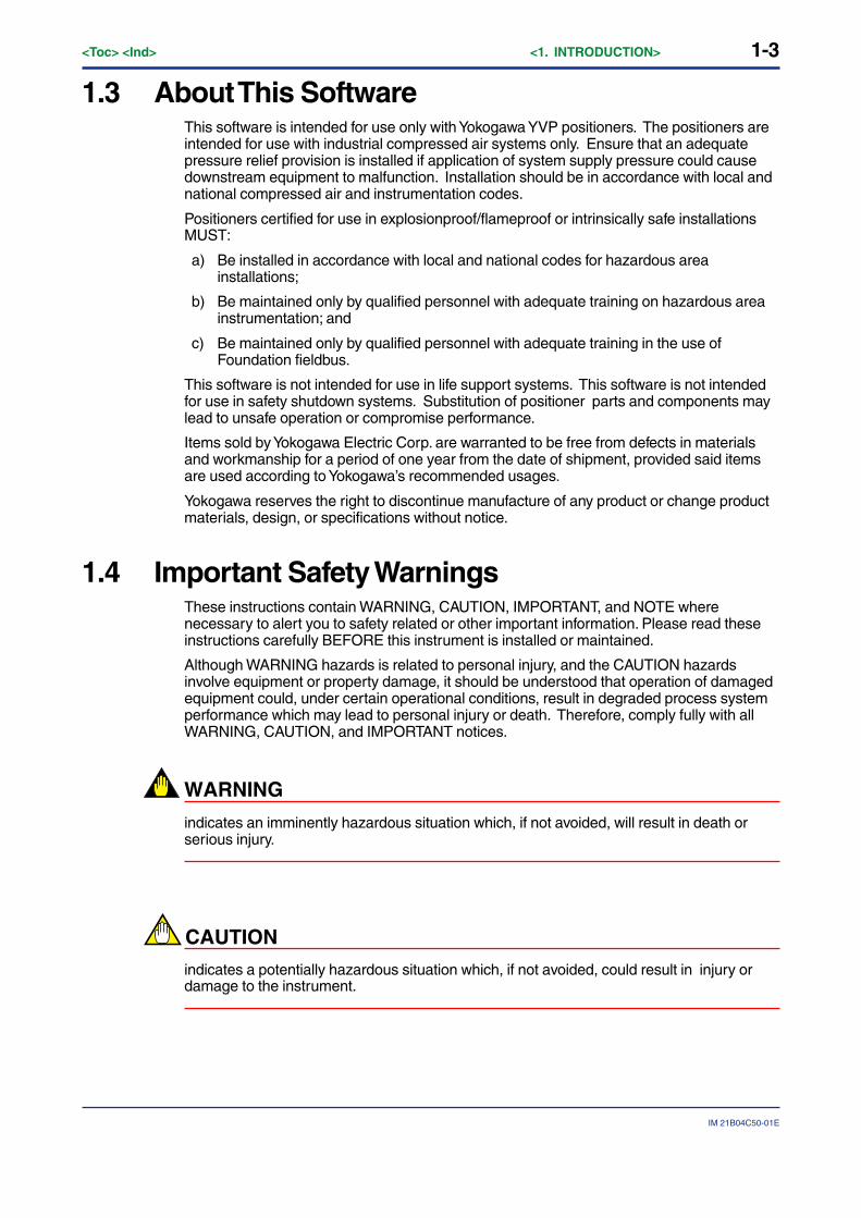
1.4 Important Safety WarningsThese instructions contain WARNING, CAUTION, IMPORTANT, and NOTE wherenecessary to alert you to safety related or other important information. Please read theseinstructions carefully BEFORE this instrument is installed or maintained.
Although WARNING hazards is related to personal injury, and the CAUTION hazardsinvolve equipment or property damage, it should be understood that operation of damagedequipment could, under certain operational conditions, result in degraded process systemperformance which may lead to personal injury or death. Therefore, comply fully with allWARNING, CAUTION, and IMPORTANT notices.
WARNING
indicates an imminently hazardous situation which, if not avoided, will result in death orserious injury.
CAUTION
indicates a potentially hazardous situation which, if not avoided, could result in injury ordamage to the instrument.
1-4<Toc> <Ind> <1. INTRODUCTION>
IM 21B04C50-01E
IMPORTANT
indicates a potentially hazardous situation which, if not avoided, may result in damage tothe instrument or a system failure.
NOTE
Indicates important facts and conditions.
1.5 Trademarks, Copyrights, and PatentsYOKOGAWA and YVP are registered trademarks of Yokogawa Electric Corporation. HARTis a registered trademark of the HART Communications Foundation. Pentium is atrademark of Intel Corporation. Internet Explorer and Windows are trademarks of MicrosoftCorporation. FOUNDATION is a trademark of the Fieldbus Foundation, Inc. NI-FBUS is atrademark of National Instruments, Inc. Netscape and Navigator are trademarks ofNetscape Communications Corporation. Masoneilan is a trademark of Dresser, Inc. Othercompany names and product names used in this manual are the registered trademarks ortrademarks of their respective owners.
2-1
IM 21B04C50-01E
<Toc> <Ind> <2. INTRODUCTION TO ValveNavi AND TO YVP>
2. INTRODUCTION TO ValveNavi
2.1 What is ValveNavi?ValveNavi is a Windows software tool that makes it easy to configure, calibrate, and operateFoundation fieldbus pneumatic control valve positioners YVP110 with internal processcontrol and limit switches. It fully supports the Foundation fieldbus specifications.
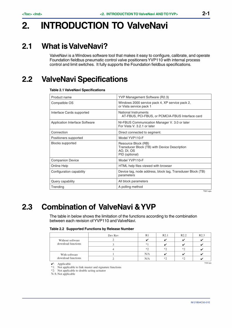
2.2 ValveNavi SpecificationsTable 2.1 ValveNavi Specifications
T001.eps
Product name YVP Management Software (R2.3)
Compatible OS Windows 2000 service pack 4, XP service pack 2, or Vista service pack 1
Interface Cards supported National InstrumentsAT-FBUS, PCI-FBUS, or PCMCIA-FBUS Interface card
Application Interface Software NI-FBUS Communication Manager V. 3.0 or laterFor Vista V. 3.2.1 or later
Connection Direct connected to segment.
Positioners supported Model YVP110-F
Blocks supported Resource Block (RB)Transducer Block (TB) with Device DescriptionAO, DI, OSPID (optional)
Companion Device Model YVP110-F
Online Help HTML help files viewed with browser
Configuration capability Device tag, node address, block tag, Transduser Block (TB) parameters
Query capability All block parameters
Trending A polling method
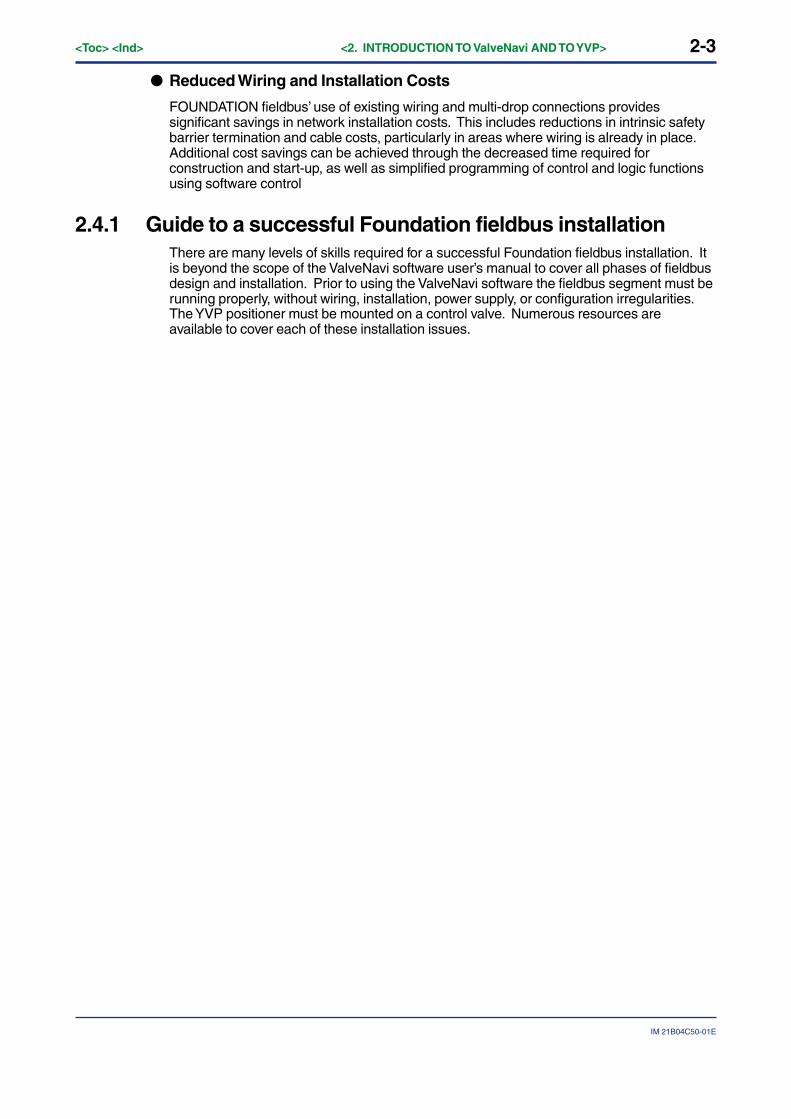
2.3 Combination of ValveNavi & YVPThe table in below shows the limitation of the functions according to the combinationbetween each revision of YVP110 and ValveNavi.
Table 2.2 Supported Functions by Release Number
T002.eps
Dev Rev
2
3
4
1
2
R1
✔
*1
*2
N/A
N/A
R2.1
✔
✔
*2
✔
*2
R2.2
✔
✔
*2
✔
*2
R2.3
✔
✔
✔
✔
✔
Without softwaredownload functions
With softwaredownload functions
✔: Applicable*1: Not applicable to link master and signature functions*2: Not applicable to double acting actuator���: Not applicable

2-2<Toc> <Ind> <2. INTRODUCTION TO ValveNavi AND TO YVP>
IM 21B04C50-01E
2.4 What is FOUNDATION® Fieldbus?The Fieldbus Foundation summarizes the technology:
FOUNDATION fieldbus is an all-digital, serial, two-way communications system that servesas a Local Area Network (LAN) for factory/plant instrumentation and control devices. Thefieldbus environment is the base level group of the digital networks in the hierarchy of plantnetworks. FOUNDATION fieldbus is used in both process and manufacturing automationapplications.
Unlike proprietary network protocols, FOUNDATION fieldbus is neither owned by anyindividual company, or regulated by a single nation or standards body. The technology iscontrolled by the Fieldbus Foundation, a not-for-profit organization consisting of more than100 of the world’s leading controls and instrumentation suppliers and end users.
While FOUNDATION fieldbus retains many of the desirable features of the 4-20 mA analogsystem, such as a standardized physical interface, bus-powered devices, and intrinsicsafety options, it offers a host of additional benefits to users.
● Device Interoperability
With interoperability, one fieldbus device can be replaced by a similar device with addedfunctionality from a different supplier on the same fieldbus network while maintainingspecified operations. This permits users to “mix and match” field devices and host systemsfrom various suppliers. Individual fieldbus devices can also transmit and receivemultivariable information, and communicate directly with each other over a commonfieldbus.
● Enhanced Process Data
With FOUNDATION fieldbus, multiple variables from each device can be brought into theplant control system for archival, trend analysis, process optimization studies, and reportgeneration. This access to accurate, high resolution data enables processes to be fine-tuned for better manufacturing throughout and reduced plant downtime. These efficienciesadd up to higher plant performance and profitability.
● Expanded View of the Process
Modern fieldbus devices, with powerful, microprocessor-based communicationscapabilities, permit process errors to be recognized faster, and with greater certainty. As aresult, plant operators are notified of abnormal conditions or the need for preventivemaintenance, and can make better production decisions. Problems that detract fromoperating efficiency are more quickly corrected, enabling yields to go up while raw materialcosts and regulatory problems decrease.
● Improved Plant Safety
Fieldbus technology will help manufacturing plants keep up with increasingly stringentsafety requirements. By providing operators with earlier notification and warning of pendingand current hazardous conditions, fieldbus allows for corrective action before an unplannedshutdown. Enhanced plant diagnostic capabilities also reduce the need for frequent accessto hazardous areas, thus minimizing the risks to field personnel.
● Easier Predictive Maintenance
Enhanced device diagnostics capabilities make it possible to monitor and record suchconditions as valve wear and transmitter fouling. Plant personnel are able to performpredictive maintenance without waiting for a scheduled shutdown, thus avoiding orreducing downtime.
2-3
IM 21B04C50-01E
<Toc> <Ind> <2. INTRODUCTION TO ValveNavi AND TO YVP>
● Reduced Wiring and Installation Costs
FOUNDATION fieldbus’ use of existing wiring and multi-drop connections providessignificant savings in network installation costs. This includes reductions in intrinsic safetybarrier termination and cable costs, particularly in areas where wiring is already in place.Additional cost savings can be achieved through the decreased time required forconstruction and start-up, as well as simplified programming of control and logic functionsusing software control
2.4.1 Guide to a successful Foundation fieldbus installationThere are many levels of skills required for a successful Foundation fieldbus installation. Itis beyond the scope of the ValveNavi software user’s manual to cover all phases of fieldbusdesign and installation. Prior to using the ValveNavi software the fieldbus segment must berunning properly, without wiring, installation, power supply, or configuration irregularities.The YVP positioner must be mounted on a control valve. Numerous resources areavailable to cover each of these installation issues.
3-1
IM 21B04C50-01E
<Toc> <Ind> <3. INSTALLATION OF HARDWARE AND SOFTWARE>
3. INSTALLATION OF HARDWARE ANDSOFTWARE
3.1 What you need to get started with ValveNaviTo begin using ValveNavi the following tools and software are needed.
• ValveNavi software on its installation CD-ROM
• A PC running Windows 2000 service pack 4 , XP service pack 2, or Vista service pack 1
• National Instruments AT-FBUS, PCI-FBUS or PCMCIA-FBUS interface card and NI-FBUS software V. 3.0 or later, for Vista V. 3.2.1 or later
• Instruction manuals for the NI-FBUS interface card and software
• The Model YVP110 positioner installed on a valve
• The Model YVP110 User’s Manual
• A Foundation fieldbus power supply and power conditioner with terminators
• Additional fieldbus devices that will be installed on the bus segment (optional)
Before we can describe installation of ValveNavi software we must first describe the pro-cess for installing the Foundation fieldbus communications hardware and software. To helpto reduce the need for terminology that used in digital communications, we will refer to anexample reference process and Foundation fieldbus segment.
3-2<Toc> <Ind> <3. INSTALLATION OF HARDWARE AND SOFTWARE>
IM 21B04C50-01E
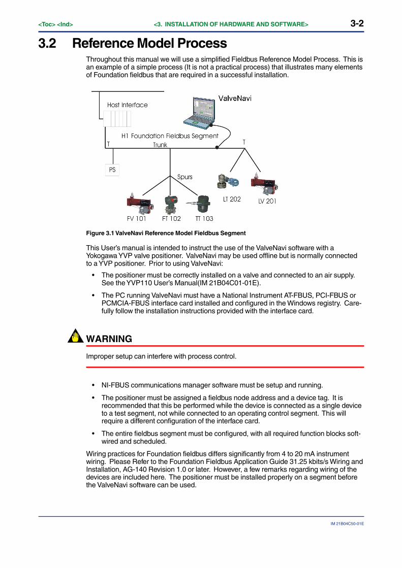
3.2 Reference Model ProcessThroughout this manual we will use a simplified Fieldbus Reference Model Process. This isan example of a simple process (It is not a practical process) that illustrates many elementsof Foundation fieldbus that are required in a successful installation.
Figure 3.1 ValveNavi Reference Model Fieldbus Segment
This User’s manual is intended to instruct the use of the ValveNavi software with aYokogawa YVP valve positioner. ValveNavi may be used offline but is normally connectedto a YVP positioner. Prior to using ValveNavi:
• The positioner must be correctly installed on a valve and connected to an air supply.See the YVP110 User’s Manual(IM 21B04C01-01E).
• The PC running ValveNavi must have a National Instrument AT-FBUS, PCI-FBUS orPCMCIA-FBUS interface card installed and configured in the Windows registry. Care-fully follow the installation instructions provided with the interface card.
WARNING
Improper setup can interfere with process control.
• NI-FBUS communications manager software must be setup and running.
• The positioner must be assigned a fieldbus node address and a device tag. It isrecommended that this be performed while the device is connected as a single deviceto a test segment, not while connected to an operating control segment. This willrequire a different configuration of the interface card.
• The entire fieldbus segment must be configured, with all required function blocks soft-wired and scheduled.
Wiring practices for Foundation fieldbus differs significantly from 4 to 20 mA instrumentwiring. Please Refer to the Foundation Fieldbus Application Guide 31.25 kbits/s Wiring andInstallation, AG-140 Revision 1.0 or later. However, a few remarks regarding wiring of thedevices are included here. The positioner must be installed properly on a segment beforethe ValveNavi software can be used.
3-3
IM 21B04C50-01E
<Toc> <Ind> <3. INSTALLATION OF HARDWARE AND SOFTWARE>
3.2.1 Wiring requirementsNote that there are cable requirements that must be met for reliable installations. The cableused must support the digital data signals without reflections, noise or attenuation. Thetype A cable should be used whenever possible and especially for long transmissiondistances or for segments with many branches (spurs).
● Power conditioner
Use a power conditioner for each segment. The conditioner must be foundation fieldbuscompliant. The power conditioner functions to isolate the digital signals from the powersource.
● Power supply
The YVP positioner complies with the foundation specification voltage requirements of 9 to32 volts. The power supply must conform to these requirements with consideration for thecurrent drawn by all devices powered by the segment. The YVP maximum currentconsumption is 17 mA.
● Terminator
Every fieldbus segment requires two (and only two) approved terminators. Terminators arepassive circuits that damp signal reflections in the circuit. For simple segments havingshort runs and few spurs, the terminator location can be at each end of the longest cable.For very short cables both terminators can even be located in the power conditioner.

3-4<Toc> <Ind> <3. INSTALLATION OF HARDWARE AND SOFTWARE>
IM 21B04C50-01E
3.3 Installing NI-FBUSValveNavi software interfaces to the fieldbus segment through an interface card that mustbe installed in the PC running ValveNavi. The card is supplied with NI-FBUS installationsoftware. ValveNavi is designed to operate only with National Instruments NI-FBUS cards,which are AT-FBUS, PCI-FBUS, or PCMCIA-FBUS.
Prior to using ValveNavi, install the NI-FBUS card and its software in accordance with theinstructions provided by National Instruments, Inc. Note that the instructions are differentfor the AT card used in a desktop and the PCMCIA card normally used with a laptop.Furthermore, the instructions are different for Windows 2000, for Windows XP, andWindows Vista.
Note that there are two NI configuration tools that serve separate purposes:
• NI-FBUS Interface Configuration Utility- This is used to install and set up interfaceboards. It provides access to IRQ and memory settings needed for Windows. Itprovides tools for importing DD’s. It is described in the Getting Started manualsupplied with the NI-FBUS interface card.
• NI-FBUS Fieldbus Configuration System- This is the tool for configuring theFoundation fieldbus network, including the devices, setting up the control strategy, andschedule. It is described in the NI-FBUS Configurator User Manual installed in theprogram online help. After opening the NI-FBUS Fieldbus Configuration System, clickHelp>>Online Help to open the manual in PDF format.
WARNING
Do not configure the interface as a Link Master when connecting to the segment with anexisting host. Disruption of control may result.
3.3.1 Configure the NI-FBUS interface card safely for differenttasksThe configuration of a portable PC for use with ValveNavi will vary depending on theimmediate task. If ValveNavi will be used to maintain or configure a valve on an existingFoundation fieldbus segment, the PC running ValveNavi must configured carefully so itdoes not interfere with control communication. Two configurations are described in thefollowing sections.
Table 3.1 Two configurations of the NI-FBUS Interface Card
T0301.EPS
To configure a positioner in the Foundation fieldbus segment with a host computer.
The NI-FBUS Interface card must be configured as a BASIC DEVICE at a Visitor address.
To configure a positioner in the segment without other host (Initial Setup, for example).
The NI-FBUS Interface card must be configured as a LINK MASTER DEVICE at a FIXED address (0�10 is recommended).
NOTE
A Visitor device will not start until connected to a running segment with an active LAS thatcan assign a node address to the visitor.

3-5
IM 21B04C50-01E
<Toc> <Ind> <3. INSTALLATION OF HARDWARE AND SOFTWARE>
● Configuring the interface card to safely connect to the Foundation fieldbussegment with a host computer
If the YVP positioner is connected on a segment that has a host computer, the interfacecard and PC must be configured as a BASIC DEVICE at a Visitor address. Open theconfiguration utility (NI-FBUS Interface Configuration Utility) and follow the instructions inthe NI manual.
Select Port and click Edit to bring up the Port dialog shown in Figure 3.2. Set theparameters exactly as shown in the figure, and click OK. (The Device Tag can be set to anyname that will be meaningful when seen by a remote interface operating on the samesegment.)
WARNING
ValveNavi is the tool for setup and maintenance. Do not connect it to the operating process.That may change the mode of YVP and cause unpredictable stop or events on the process.Use it only when the process is OFFLINE.
Figure 3.2 NI-FBUS Interface configuration utility setting the card as a Basic Device

3-6<Toc> <Ind> <3. INSTALLATION OF HARDWARE AND SOFTWARE>
IM 21B04C50-01E
● Configure the interface card for one to one Communication
The visitor configuration described previously will not work if the only devices that areconnected to the segment are YVP positioner and the NI-FBUS interface card, becausethere will be no link master to schedule messages. It is necessary, therefore, to configurethe interface card as a link master, exactly as shown in Figure 3.3. (The interface name andDevice Tag may be any convenient names. The names will not be seen by any otherinterfaces and are not important.)
Figure 3.3 Configure the interface as Link Master
3.3.2 Installing the Device Descripfions (DD) with NI-FBUSInterface Configuration UtilityThe NI-FBUS Interface Configuration Utility must be used to install the DD for the YVP, andalso to install the standard dictionary. If you do not have the DD file, you can download itfrom our web site. Visit the following web site or contact our subsidiaries.
http://www.yokogawa.com/fld
Step 1 Click [Import DD/CFF] and in the new dialog click [Browse]. Select thedesired .ffo file or .cff file and click [Open]. In the import DD dialog click [OK]
Step 2 Repeat for each device that will communicate with ValveNavi.
3-7
IM 21B04C50-01E
<Toc> <Ind> <3. INSTALLATION OF HARDWARE AND SOFTWARE>
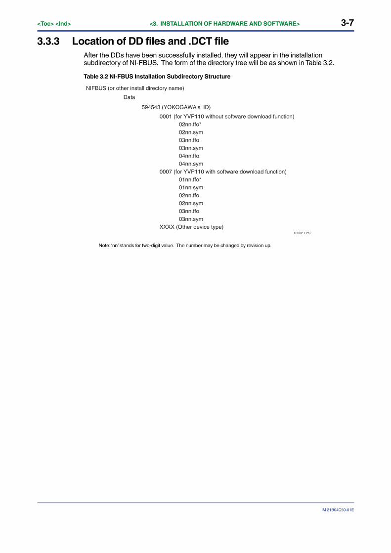
3.3.3 Location of DD files and .DCT fileAfter the DDs have been successfully installed, they will appear in the installationsubdirectory of NI-FBUS. The form of the directory tree will be as shown in Table 3.2.
Table 3.2 NI-FBUS Installation Subdirectory Structure
NIFBUS (or other install directory name)
Data
594543 (YOKOGAWA's ID)
T0302.EPS
0001 (for YVP110 without software download function) 02nn.ffo* 02nn.sym 03nn.ffo 03nn.sym 04nn.ffo 04nn.sym0007 (for YVP110 with software download function) 01nn.ffo* 01nn.sym 02nn.ffo 02nn.sym 03nn.ffo 03nn.symXXXX (Other device type)
Note: ‘nn’ stands for two-digit value. The number may be changed by revision up.
4-1
IM 21B04C50-01E
<Toc> <Ind> <4. ValveNavi ADMINISTRATION>
4. ValveNavi ADMINISTRATIONIn the previous chapter, we described the installation of the Foundation fieldbuscommunications software and hardware. In this chapter, we will describe theprocedures for installing ValveNavi software.
The ValveNavi installation procedures outlined in this chapter assume a workingknowledge of Microsoft Windows, the Yokogawa YVP positioner, and of Foundationfieldbus communications and function block technology. For further informationabout the YVP positioner, see YVP110 User’s Manual (IM 21B04C01-01E).
4.1 Hardware and Software RequirementsValveNavi runs on a standard IBM-compatible computer. To successfully install and runValveNavi, the computer system must meet minimum hardware and software requirements.The following lists the minimum hardware and software requirements:
• Windows 2000 service pack 4, XP service pack 2, or Vista service pack 1 operatingsystem
• Pentium 166 MHz microprocessor or faster
• CD-ROM drive
• National Instruments NI-FBUS interface card and server software
• 500 MB of free hard disk space to install and run ValveNavi
4.2 Installing ValveNaviValveNavi is distributed on a CD-ROM for Windows 2000, Windows XP, or Windows Vista.
1. Insert the ValveNavi installation CD-ROM into the CD-ROM drive.2. Click Start > Run, then type x:setup (x is the letter of the CD-ROM drive.)3. Follow the prompts on your screen to complete the installation process.
ValveNavi Administration and ValveNavi Help are also installed along with ValveNavi. Aftersuccessful installation of ValveNavi software, the system administrator of ValveNavi shouldchange the default logon and password and set up user accounts through the ValveNaviAdministration program. Secure the ValveNavi CD-ROM in order to provide systemsecurity. Anyone with access to the setup disk could reload the software and thereby getaccess to YVP devices. For more details, see 4.6.
NOTE
In case of ValveNavi install folder (ex: C¥Program Files¥ValveNavi) is not writable, somefunctions can not be used.
4-2<Toc> <Ind> <4. ValveNavi ADMINISTRATION>
IM 21B04C50-01E
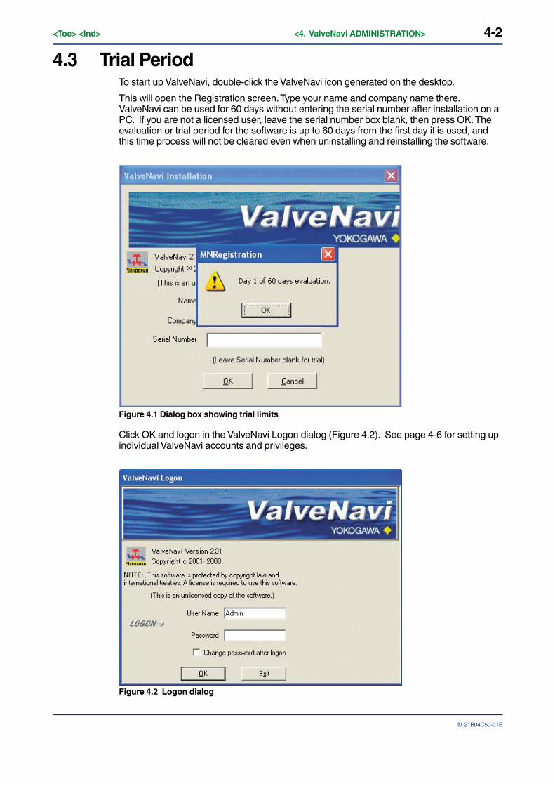
4.3 Trial PeriodTo start up ValveNavi, double-click the ValveNavi icon generated on the desktop.
This will open the Registration screen. Type your name and company name there.ValveNavi can be used for 60 days without entering the serial number after installation on aPC. If you are not a licensed user, leave the serial number box blank, then press OK. Theevaluation or trial period for the software is up to 60 days from the first day it is used, andthis time process will not be cleared even when uninstalling and reinstalling the software.
Figure 4.1 Dialog box showing trial limits
Click OK and logon in the ValveNavi Logon dialog (Figure 4.2). See page 4-6 for setting upindividual ValveNavi accounts and privileges.
Figure 4.2 Logon dialog
4-3
IM 21B04C50-01E
<Toc> <Ind> <4. ValveNavi ADMINISTRATION>
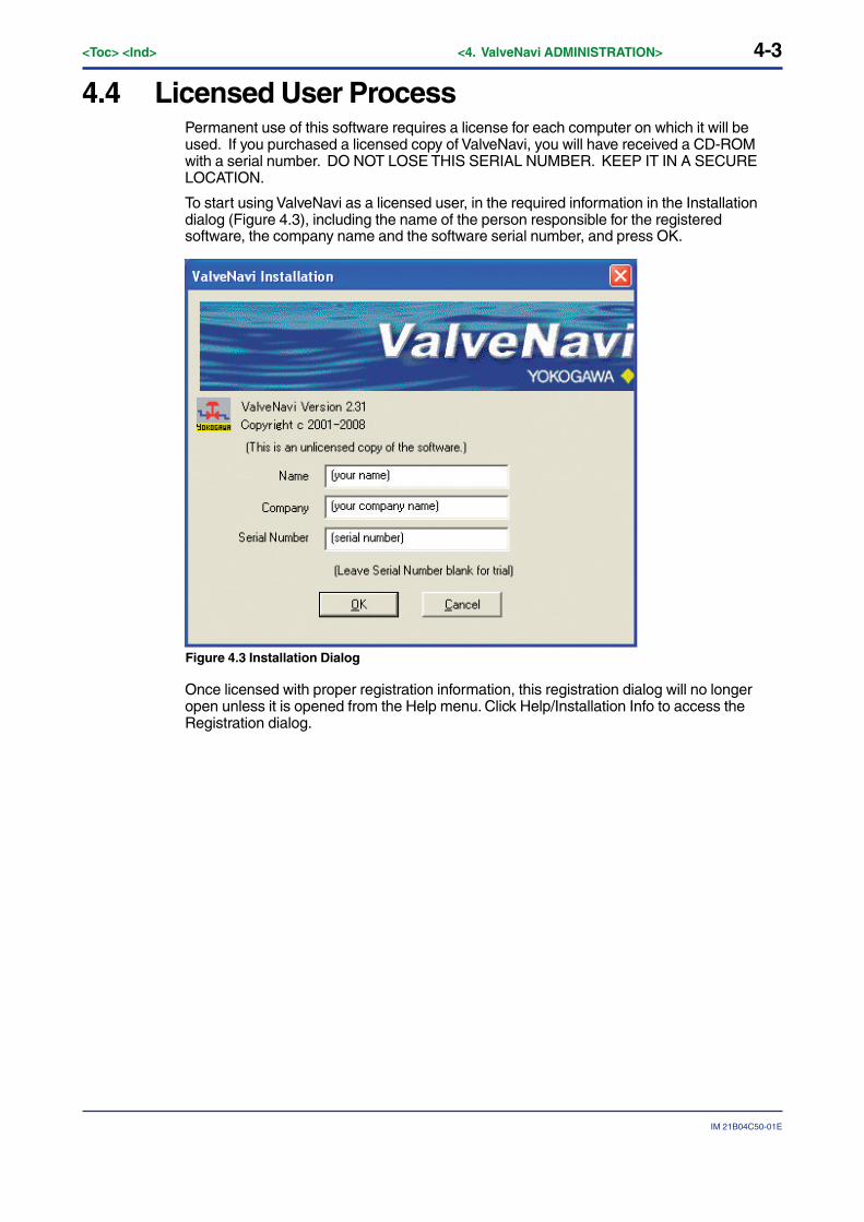
4.4 Licensed User ProcessPermanent use of this software requires a license for each computer on which it will beused. If you purchased a licensed copy of ValveNavi, you will have received a CD-ROMwith a serial number. DO NOT LOSE THIS SERIAL NUMBER. KEEP IT IN A SECURELOCATION.
To start using ValveNavi as a licensed user, in the required information in the Installationdialog (Figure 4.3), including the name of the person responsible for the registeredsoftware, the company name and the software serial number, and press OK.
Figure 4.3 Installation Dialog
Once licensed with proper registration information, this registration dialog will no longeropen unless it is opened from the Help menu. Click Help/Installation Info to access theRegistration dialog.
4-4<Toc> <Ind> <4. ValveNavi ADMINISTRATION>
IM 21B04C50-01E
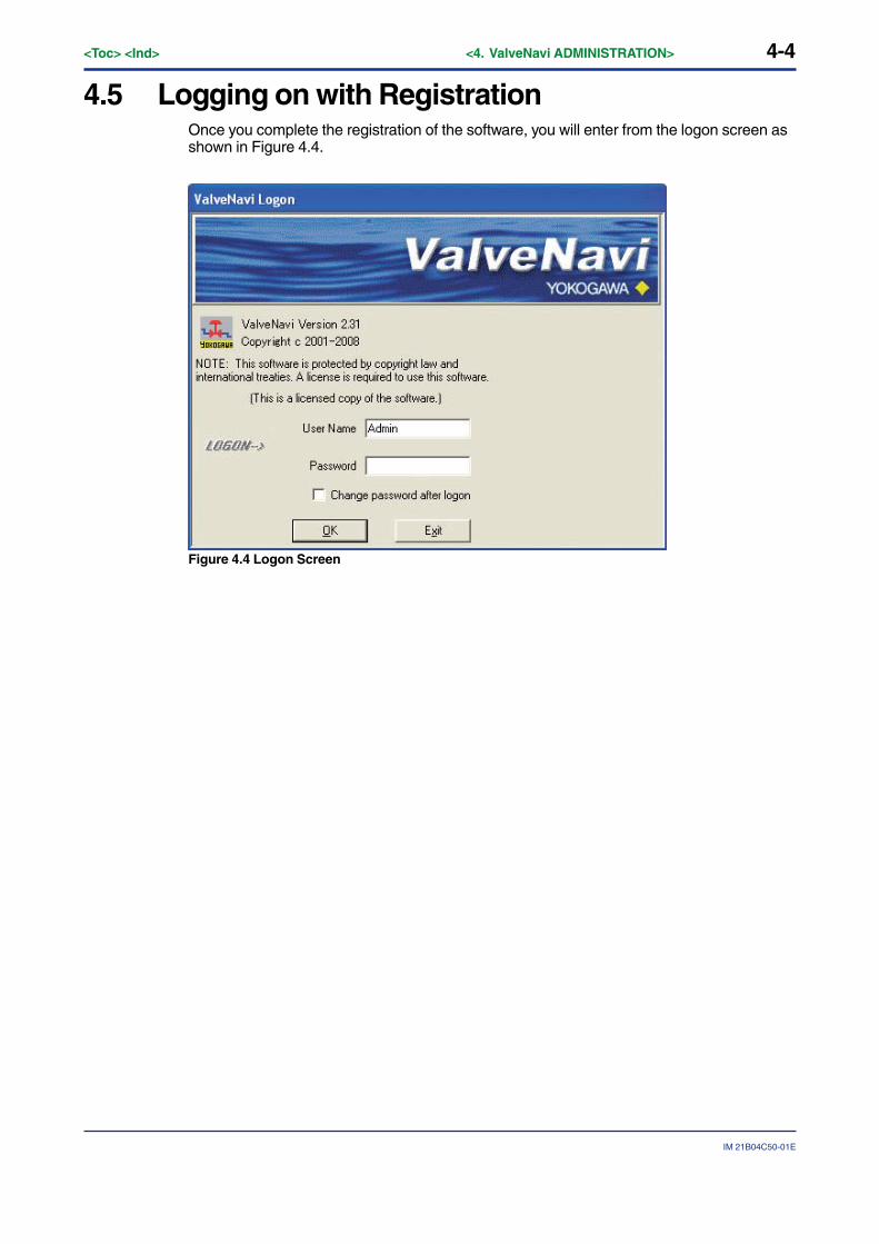
4.5 Logging on with RegistrationOnce you complete the registration of the software, you will enter from the logon screen asshown in Figure 4.4.
Figure 4.4 Logon Screen
4-5
IM 21B04C50-01E
<Toc> <Ind> <4. ValveNavi ADMINISTRATION>
4.6 Setting Up User Accounts
4.6.1 System Administration, Passwords, and Privilege LevelsIn a plant with many users with various levels of training and responsibility, it is oftendesirable to restrict certain users access to a limited range of functions. Starting theValveNavi program requires a valid account with a user name and a password for eachuser. The privilege level associated with a ValveNavi account determines which functionsof the program the user is allowed to access.
The ValveNavi Administration program allows the administrator to perform all user accountadministrative functions to run ValveNavi and to control access to the functionality of theYVP positioner.
These administrative functions include:
• Adding new user accounts
• Deleting existing user accounts
• Changing existing user accounts
• Adjusting privilege levels
4.6.2 Start the Administration ProgramAfter installation of ValveNavi, the ValveNavi administrator should change the defaultpasswords, set up the initial user accounts through the Admin program, and secure thesetup disk. Anyone with access to the setup disk could reload the software and thereby getaccess to YVP devices.
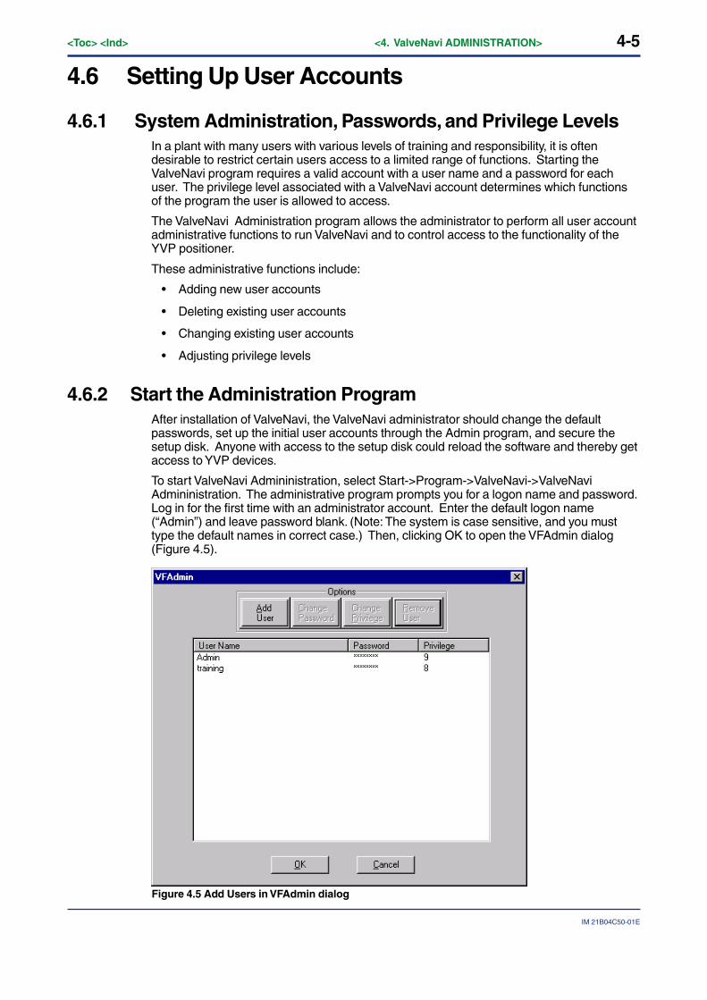
To start ValveNavi Admininistration, select Start->Program->ValveNavi->ValveNaviAdmininistration. The administrative program prompts you for a logon name and password.Log in for the first time with an administrator account. Enter the default logon name(“Admin”) and leave password blank. (Note: The system is case sensitive, and you musttype the default names in correct case.) Then, clicking OK to open the VFAdmin dialog(Figure 4.5).
Figure 4.5 Add Users in VFAdmin dialog
4-6<Toc> <Ind> <4. ValveNavi ADMINISTRATION>
IM 21B04C50-01E
The program already contains two accounts.
• The first account is the administrator account, which you are using, with the logonname “Admin” (note that this is case sensitive with a capital A) and the initial passwordis blank (no password). Immediately use the administration program to install apassword for administration to make the system secure from unauthorized use.
• The second account enables use of the YVP process controller simulator with thelogon name of “training” (lower case) and password of “training” (lower case). Theprocess control simulator will simulate, in software, a process with a dead time of onesecond and a lag of five seconds. The process controller simulator is useful fortraining users on the many functions and features of the YVP positioner and its PIDfunction block.
WARNING
Do not logon with a “training” account to use ValveNavi with a valve that is not isolated fromthe operating process. Control links will be destroyed by using the simulate function.
CAUTION
It is important that the administrator change the default logon names and passwords for theadministrator account and the training account. Continued use of the default logon accountnames and passwords makes the system less secure.
4.6.3 Privilege LevelsEach user is assigned an account. For each account, there is an associated privilege level.Privilege levels range from 0 to 9, with level 0 the lowest and 9 the highest. The followingdefines several privilege levels, which control access to specific functions of the ValveNaviprogram. Services which are not accessible to a particular level are “grayed” out.
Level 0
Allows the user to logon to ValveNavi only if the connected YVP is in Auto. The user cansend commands that will reply with configuration, calibration, and status information, butthe user cannot change any information. Level 0 users cannot go to Out Of Service orManual.
Level 1
Allows the user access Auto, Manual or Out Of Service states. The user can transfer fromone mode or state to another (i.e. the user can take the YVP out of Auto and put it inManual). The user can then set valve position. However, the user cannot change thecalibration or configuration. The level 1 user cannot access the PID dialog.
Level 2
This level is not defined.
Level 3
Allows the user to change the configuration or calibration values, but does not allow theuser to perform calibration and tuning operations that stroke the valve (Find Stops,Autotune or diagnostics).
The user may open the PID dialog and use it to change PID modes and to move the valvein manual or change process variable setpoint. The user can enter tuning parameters forthe process variable PID control.

4-7
IM 21B04C50-01E
<Toc> <Ind> <4. ValveNavi ADMINISTRATION>
Level 4
Allows the user to perform all operations except Download Configuration to YVP.
Level 5
This level is not defined.
Level 6
This level is not defined.
Level 7
This level is not defined.
Level 8
This level is intended for training and should be used cautiously. It grants all of theprivileges of level 4 plus allows access to the Simulation State of the process controller.(The simulation of the PID Block allows the user to run the process controller withoutconnecting a process variable input to the YVP and is useful for learning how to operate theprocess controller).
WARNING
The simulation state must not be used if the valve is connected in a control loop or the if thevalve is controlling process flow.
The simulation state will permanently remove important control loop configurationinformation from the YVP valve positioner. The soft-wired connection between the PIDfunctions block and its input function block must be restored after simulation is used.
Reconfigure function block links after using simulate. The Clear Device command must beused when downloading restored configuration.
Level 9
Allows access to all YVP functions. In addition, it is the only level allowed to logon to theadministration program.
The administrator has an account of privilege level 9. There must be at least one user ofprivilege level 9 in order to get access to the administration program.
4-8<Toc> <Ind> <4. ValveNavi ADMINISTRATION>
IM 21B04C50-01E
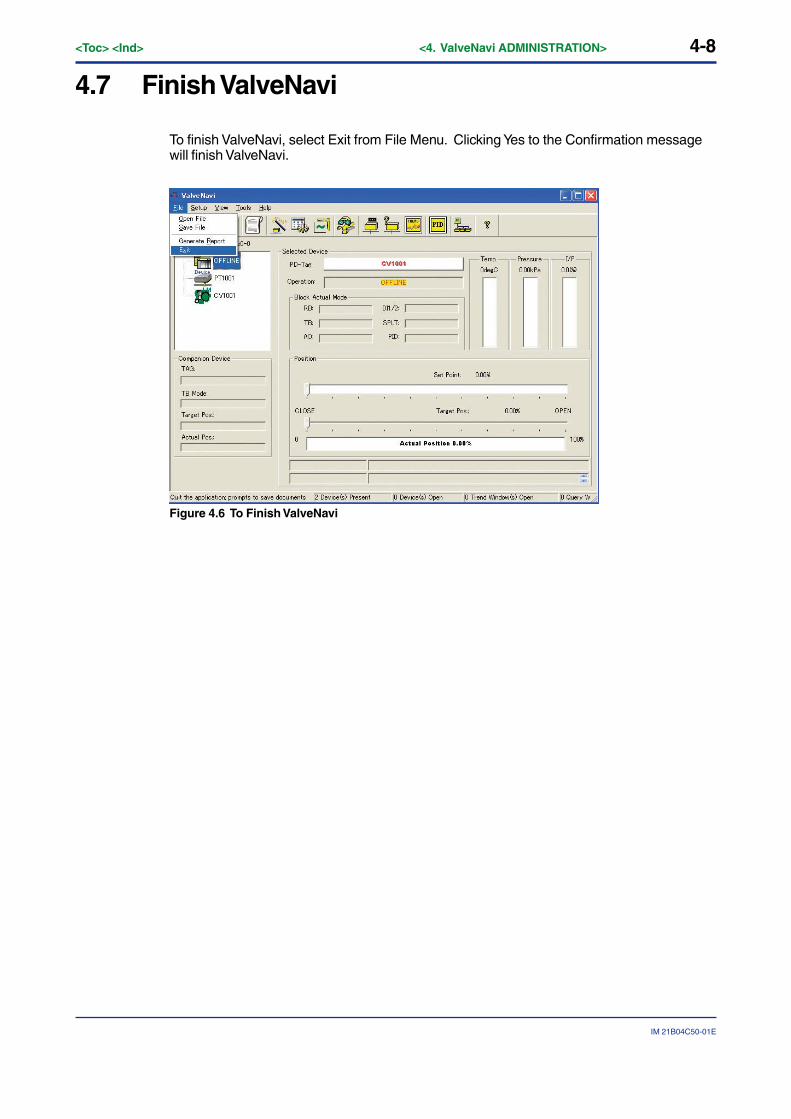
4.7 Finish ValveNavi
To finish ValveNavi, select Exit from File Menu. Clicking Yes to the Confirmation messagewill finish ValveNavi.
Figure 4.6 To Finish ValveNavi
5-1
IM 21B04C50-01E
<Toc> <Ind> <5. FOUNDATION FIELDBUS OVERVIEW>
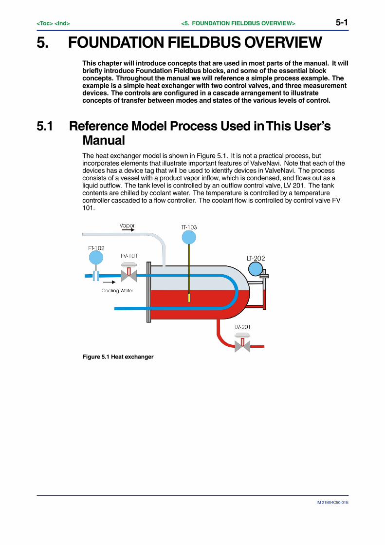
5. FOUNDATION FIELDBUS OVERVIEWThis chapter will introduce concepts that are used in most parts of the manual. It willbriefly introduce Foundation Fieldbus blocks, and some of the essential blockconcepts. Throughout the manual we will reference a simple process example. Theexample is a simple heat exchanger with two control valves, and three measurementdevices. The controls are configured in a cascade arrangement to illustrateconcepts of transfer between modes and states of the various levels of control.
5.1 Reference Model Process Used in This User’sManualThe heat exchanger model is shown in Figure 5.1. It is not a practical process, butincorporates elements that illustrate important features of ValveNavi. Note that each of thedevices has a device tag that will be used to identify devices in ValveNavi. The processconsists of a vessel with a product vapor inflow, which is condensed, and flows out as aliquid outflow. The tank level is controlled by an outflow control valve, LV 201. The tankcontents are chilled by coolant water. The temperature is controlled by a temperaturecontroller cascaded to a flow controller. The coolant flow is controlled by control valve FV101.
Figure 5.1 Heat exchanger
5-2<Toc> <Ind> <5. FOUNDATION FIELDBUS OVERVIEW>
IM 21B04C50-01E
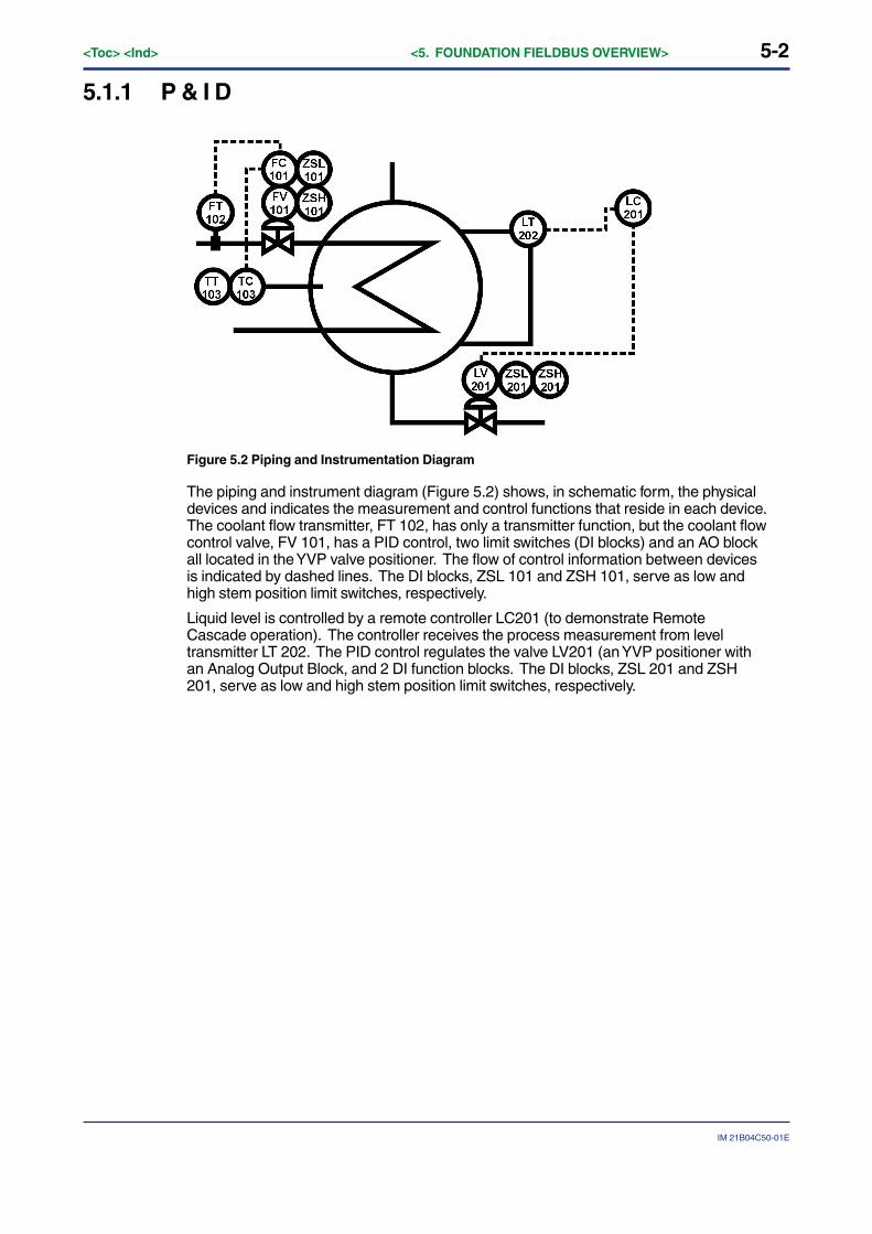
5.1.1 P & I D
Figure 5.2 Piping and Instrumentation Diagram
The piping and instrument diagram (Figure 5.2) shows, in schematic form, the physicaldevices and indicates the measurement and control functions that reside in each device.The coolant flow transmitter, FT 102, has only a transmitter function, but the coolant flowcontrol valve, FV 101, has a PID control, two limit switches (DI blocks) and an AO blockall located in the YVP valve positioner. The flow of control information between devicesis indicated by dashed lines. The DI blocks, ZSL 101 and ZSH 101, serve as low andhigh stem position limit switches, respectively.
Liquid level is controlled by a remote controller LC201 (to demonstrate RemoteCascade operation). The controller receives the process measurement from leveltransmitter LT 202. The PID control regulates the valve LV201 (an YVP positioner withan Analog Output Block, and 2 DI function blocks. The DI blocks, ZSL 201 and ZSH201, serve as low and high stem position limit switches, respectively.
5-3
IM 21B04C50-01E
<Toc> <Ind> <5. FOUNDATION FIELDBUS OVERVIEW>
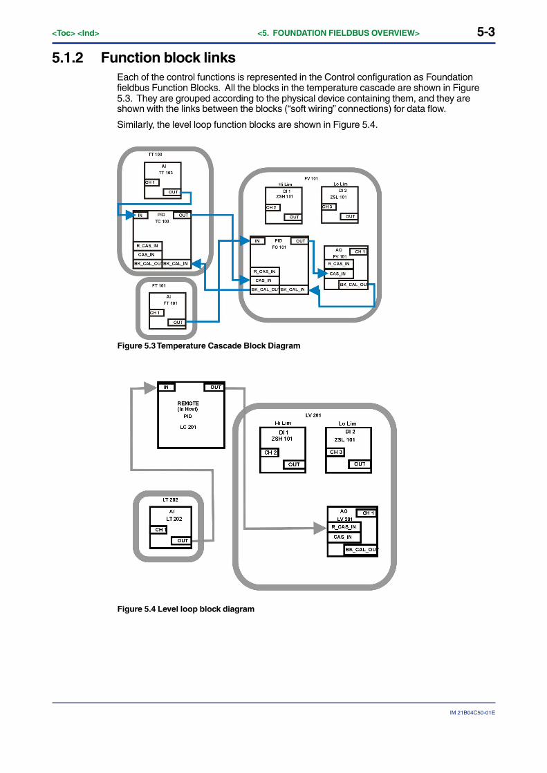
5.1.2 Function block linksEach of the control functions is represented in the Control configuration as Foundationfieldbus Function Blocks. All the blocks in the temperature cascade are shown in Figure5.3. They are grouped according to the physical device containing them, and they areshown with the links between the blocks (“soft wiring” connections) for data flow.
Similarly, the level loop function blocks are shown in Figure 5.4.
Figure 5.3 Temperature Cascade Block Diagram
Figure 5.4 Level loop block diagram
5-4<Toc> <Ind> <5. FOUNDATION FIELDBUS OVERVIEW>
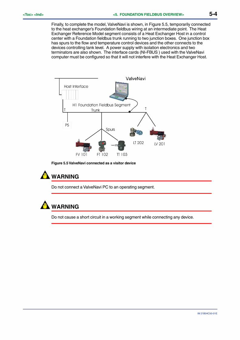
IM 21B04C50-01E
Finally, to complete the model, ValveNavi is shown, in Figure 5.5, temporarily connectedto the heat exchanger’s Foundation fieldbus wiring at an intermediate point. The HeatExchanger Reference Model segment consists of a Heat Exchanger Host in a controlcenter with a Foundation fieldbus trunk running to two junction boxes. One junction boxhas spurs to the flow and temperature control devices and the other connects to thedevices controlling tank level. A power supply with isolation electronics and twoterminators are also shown. The interface cards (NI-FBUS ) used with the ValveNavicomputer must be configured so that it will not interfere with the Heat Exchanger Host.
Figure 5.5 ValveNavi connected as a visitor device
WARNING
Do not connect a ValveNavi PC to an operating segment.
WARNING
Do not cause a short circuit in a working segment while connecting any device.

5-5
IM 21B04C50-01E
<Toc> <Ind> <5. FOUNDATION FIELDBUS OVERVIEW>
5.2 Device Operational States and Block Modes
Figure 5.6 Device Operation State in Pop-up Menu
The Operation State can be accessed several ways. From the Device Selection frame,right click the desired device to pop up a menu list and select Device Operation State. Inthe tool bar click the Device Operation State icon. Or choose Tools>Device operation Statefrom the Menu bar.
The Device operation State dialog will then appear offering choice of Out Of Service,Manual and Normal states.
Figure 5.7 Device Operation State Dialog
5-6<Toc> <Ind> <5. FOUNDATION FIELDBUS OVERVIEW>
IM 21B04C50-01E
ValveNavi manages the operational states of the positioner and its embedded PID control-ler by controlling the target modes for each of the function blocks. The actual mode of eachblock may be different from the target mode. The actual mode is controlled by the blockitself in accordance with mode rules based on the quality of the data and modes of thelinked blocks. A brief summary of modes follows, but a thorough discussion of modes isbeyond the scope of this instruction. The interested reader is referred to the FieldbusFoundation that specifies the formal rules for mode changing.
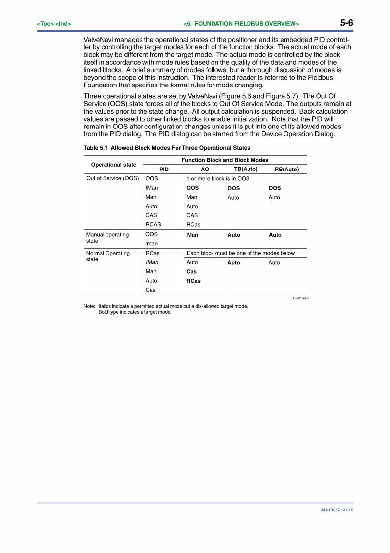
Three operational states are set by ValveNavi (Figure 5.6 and Figure 5.7). The Out OfService (OOS) state forces all of the blocks to Out Of Service Mode. The outputs remain atthe values prior to the state change. All output calculation is suspended. Back calculationvalues are passed to other linked blocks to enable initialization. Note that the PID willremain in OOS after configuration changes unless it is put into one of its allowed modesfrom the PID dialog. The PID dialog can be started from the Device Operation Dialog.
Table 5.1 Allowed Block Modes For Three Operational States
Operational stateFunction Block and Block Modes
Out of Service (OOS)
PID AO TB(Auto) RB(Auto)
OOS
IMan
Man
Auto
CAS
RCAS
1 or more block is in OOS
OOS
Man
Auto
CAS
RCas
OOS
Auto
OOS
Auto
Manual operating state
OOS
Iman
Normal Operating state
RCas
IMan
Man
Auto
Cas
Each block must be one of the modes below
Auto
Cas
RCas
Auto Auto
T0501.EPS
Man Auto Auto
Note: Italics indicate a permitted actual mode but a dis-allowed target mode.Bold type indicates a target mode.
5-7
IM 21B04C50-01E
<Toc> <Ind> <5. FOUNDATION FIELDBUS OVERVIEW>
5.3 Block ModesAll blocks (function/transducer/resource) have operating modes. There are eight modesdefined in the Foundation fieldbus specification. Not all modes are supported by everyblock. For example, the Discrete Input (DI) block supports just Auto, Man, and OOS. Theaction of the modes are described in the following paragraphs. Transfers between modesare managed by the function blocks in response to manual commands, in response tochanges in the modes of linked blocks, and in response to changes in the quality of theparameters that are transmitted. Control and status options can be set to manage modechanging behavior.
(1) Remote-Output (Rout)
The block output is being set by a Control Application running on an interface Devicethrough the remote-output-in parameter. The algorithm is bypassed and the remote blockcontrols its output directly. The algorithm must initialize so no bump is experienced whenthe mode switches to auto. A remote-output-out parameter is maintained by the block tosupport initialization of the control application when the block mode is not remote-output.The setpoint may be maintained or, optionally, be initialized to the process variable value.
(2) Remote-Cascade (RCas)
The block setpoint is being set by a Control Application running on an interface devicethrough the remote-cascade in parameter. Based on this setpoint, the normal blockalgorithm determines the primary output value. A remote-cascade out parameter ismaintained by the block to support initialization of the control application when the blockmode is not remote-cascade.
(3) Cascade (Cas)
A setpoint value supplied by another function block through the Cascade input parameter isused by the normal block algorithm in determining the primary output value. Thisconnection between function blocks is defined by a link object.
(4) Automatic (Auto)
A local setpoint value is used by the normal block algorithm in determining the primaryoutput value. The local setpoint value may be written by an operator through an interfacedevice.
(5) Manual (Man)
The block output is not being calculated, although it may be limited. It is directly set by theoperator through an interface device. The algorithm must initialize so no bump isexperienced when the mode switches. The setpoint may be maintained or, optionally, beinitialized to the process variable parameter value or to the setpoint value associated withthe previous (retained) target mode.
(6) Local Override (LO)
Applies to control and output blocks that support a track input parameter. In the localoverride mode, the block output is being set to track the value of the track input parameter.The algorithm must initialize so no bump is experienced when the mode switches from LOback to the target mode. The setpoint may be maintained or, optionally, be initialized to theprocess variable parameter value.
(7) Initialization Manual (IMan)
The block output is being set in response to the back-calculation input parameter status.When the status indicates there is no path to the final output element, then the controlblocks must initialize to provide for bumpless transfer when the condition clears. A back-calculation out parameter is supported by all output and control class function blocks. Thesetpoint may be maintained or, optionally, initialized to the process variable parametervalue.
5-8<Toc> <Ind> <5. FOUNDATION FIELDBUS OVERVIEW>
IM 21B04C50-01E
(8) Out of Service (OOS)
The block is not being evaluated. The output and setpoint are maintained at last value.
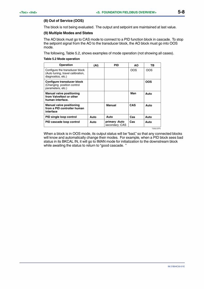
(9) Multiple Modes and States
The AO block must go to CAS mode to connect to a PID function block in cascade. To stopthe setpoint signal from the AO to the transducer block, the AO block must go into OOSmode.
The following, Table 5.2, shows examples of mode operation (not showing all cases).
Table 5.2 Mode operation
Operation
Configure the transducer block(Auto tuning, travel calibration, diagnostics, etc.)
Configure transducer block(Changing position control parameters, etc.)
Manual valve positioning from ValveNavi or other human interface.
Manual valve positioning from a PID controller human interface
PID single loop control
PID cascade loop control
(AI) AO TBPID
OOS
Man
Manual
Auto Auto
Auto
CAS
Cas
Cas
Auto
Auto
OOS
primary :Autosecondary :CAS
OOS
Auto
Auto
T0502.EPS
When a block is in OOS mode, its output status will be “bad,” so that any connected blockswill know and automatically change their modes. For example, when a PID block sees badstatus in its BKCAL IN, it will go to IMAN mode for initialization to the downstream blockwhile awaiting the status to return to “good cascade. ”
5-9
IM 21B04C50-01E
<Toc> <Ind> <5. FOUNDATION FIELDBUS OVERVIEW>
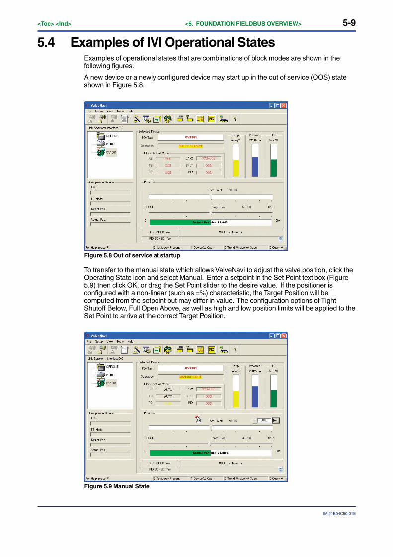
5.4 Examples of IVI Operational StatesExamples of operational states that are combinations of block modes are shown in thefollowing figures.
A new device or a newly configured device may start up in the out of service (OOS) stateshown in Figure 5.8.
Figure 5.8 Out of service at startup
To transfer to the manual state which allows ValveNavi to adjust the valve position, click theOperating State icon and select Manual. Enter a setpoint in the Set Point text box (Figure5.9) then click OK, or drag the Set Point slider to the desire value. If the positioner isconfigured with a non-linear (such as =%) characteristic, the Target Position will becomputed from the setpoint but may differ in value. The configuration options of TightShutoff Below, Full Open Above, as well as high and low position limits will be applied to theSet Point to arrive at the correct Target Position.
Figure 5.9 Manual State
5-10<Toc> <Ind> <5. FOUNDATION FIELDBUS OVERVIEW>
IM 21B04C50-01E
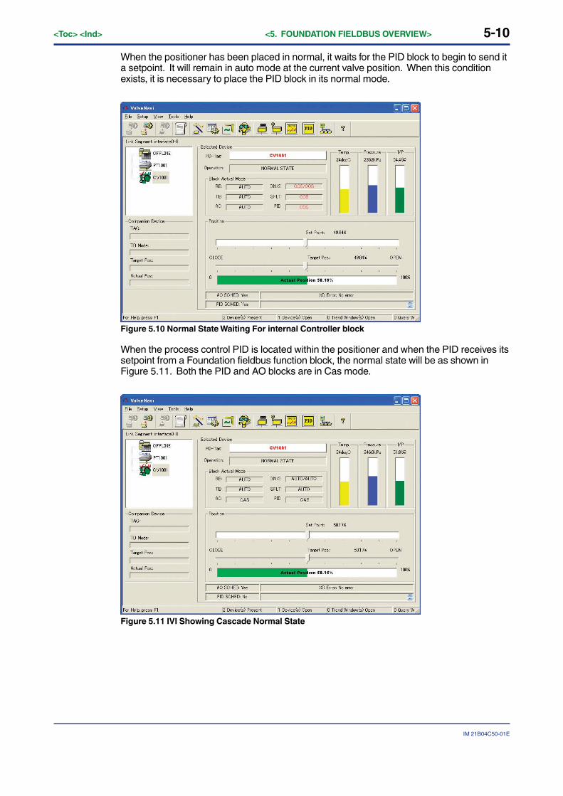
When the positioner has been placed in normal, it waits for the PID block to begin to send ita setpoint. It will remain in auto mode at the current valve position. When this conditionexists, it is necessary to place the PID block in its normal mode.
Figure 5.10 Normal State Waiting For internal Controller block
When the process control PID is located within the positioner and when the PID receives itssetpoint from a Foundation fieldbus function block, the normal state will be as shown inFigure 5.11. Both the PID and AO blocks are in Cas mode.
Figure 5.11 IVI Showing Cascade Normal State
5-11
IM 21B04C50-01E
<Toc> <Ind> <5. FOUNDATION FIELDBUS OVERVIEW>
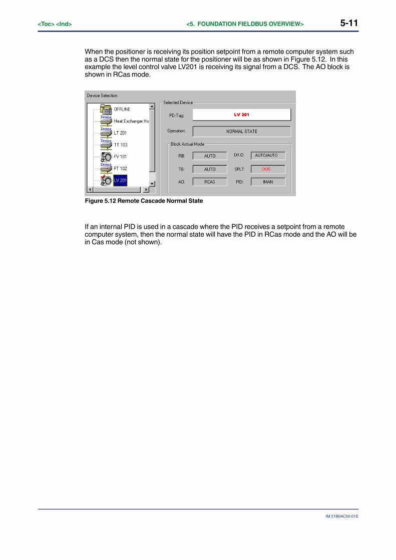
When the positioner is receiving its position setpoint from a remote computer system suchas a DCS then the normal state for the positioner will be as shown in Figure 5.12. In thisexample the level control valve LV201 is receiving its signal from a DCS. The AO block isshown in RCas mode.
Figure 5.12 Remote Cascade Normal State
If an internal PID is used in a cascade where the PID receives a setpoint from a remotecomputer system, then the normal state will have the PID in RCas mode and the AO will bein Cas mode (not shown).
5-12<Toc> <Ind> <5. FOUNDATION FIELDBUS OVERVIEW>
IM 21B04C50-01E
5.5 Changing Operational StatesThe Foundation fieldbus Application process specifies the mode handling for interoperablefunction blocks. It also specifies which mode a block must be in when each parameter iswritten. ValveNavi provides an intelligent, optimized process for managing configurationand calibration changes. For efficiency, it does not place blocks into Out Of Service modeunless the parameter requires OOS. It analyzes the requested changes and then sets thecorrect mode for each affected function block. The actual block modes are displayed in theIVI.
The Foundation fieldbus specifies a mechanism for transferring between function blockmodes. The user declares a target for the block mode, but the actual mode is set by theblock in accordance with rules. The rules allow modes based on the quality of input dataand quality of the connection to the process. YVP function blocks comply with the FF rules.ValveNavi sets target modes for individual function blocks as required by configuration,calibration, diagnostics and other services. It sets target modes for group of function blocksto achieve three operational states of the positioner: Out of Service, Manual, and Normal.
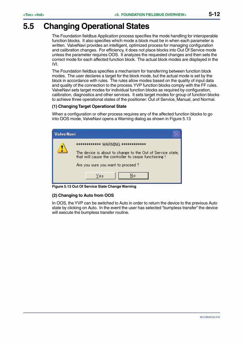
(1) Changing Target Operational State
When a configuration or other process requires any of the affected function blocks to gointo OOS mode, ValveNavi opens a Warning dialog as shown in Figure 5.13
Figure 5.13 Out Of Service State Change Warning
(2) Changing to Auto from OOS
In OOS, the YVP can be switched to Auto in order to return the device to the previous Autostate by clicking on Auto. In the event the user has selected “bumpless transfer” the devicewill execute the bumpless transfer routine.

6-1
IM 21B04C50-01E
<Toc> <Ind> <6. QUICK TOUR OF ValveNavi>
6. QUICK TOUR OF ValveNaviIn the quick tour we will briefly introduce each of the tools provided by ValveNavi.The chapters that describe the tools in details follow the quick tour.
6.1 IntroductionValveNavi uses an integrated valve interface, IVI, to display all valve and positionervariables and to provide access to services, such as configuration and calibration tools.The information and controls for services are arranged in frames within IVI. From the IVIthe user has single click access to the PID Controller interface. IVI displays and updatesreal time values for valve position, valve setpoint and actuator pressure numerically andgraphically.
Data objects are grouped in “frames” within the IVI display as described below.
Figure 6.1 Integrated Valve Interface (IVI)

6-2<Toc> <Ind> <6. QUICK TOUR OF ValveNavi>
IM 21B04C50-01E
6.2 Fieldbus Device TreeAll of the devices on the bus segment live list are shown as icons in the Device Selection box.
Figure 6.2 Device Tree
Click on the YVP device to open a communications session with the positioner. Thefieldbus segment live list is continuously scanned and devices are shown when present.Devices that have communications failure are shown with a red X. The selected device isshown with a red check-mark.
When a device is selected, a warning dialog informs that an attempt is made to connect toa new device. Then the Read configuration dialog displays progress uploading device data.
6-3
IM 21B04C50-01E
<Toc> <Ind> <6. QUICK TOUR OF ValveNavi>
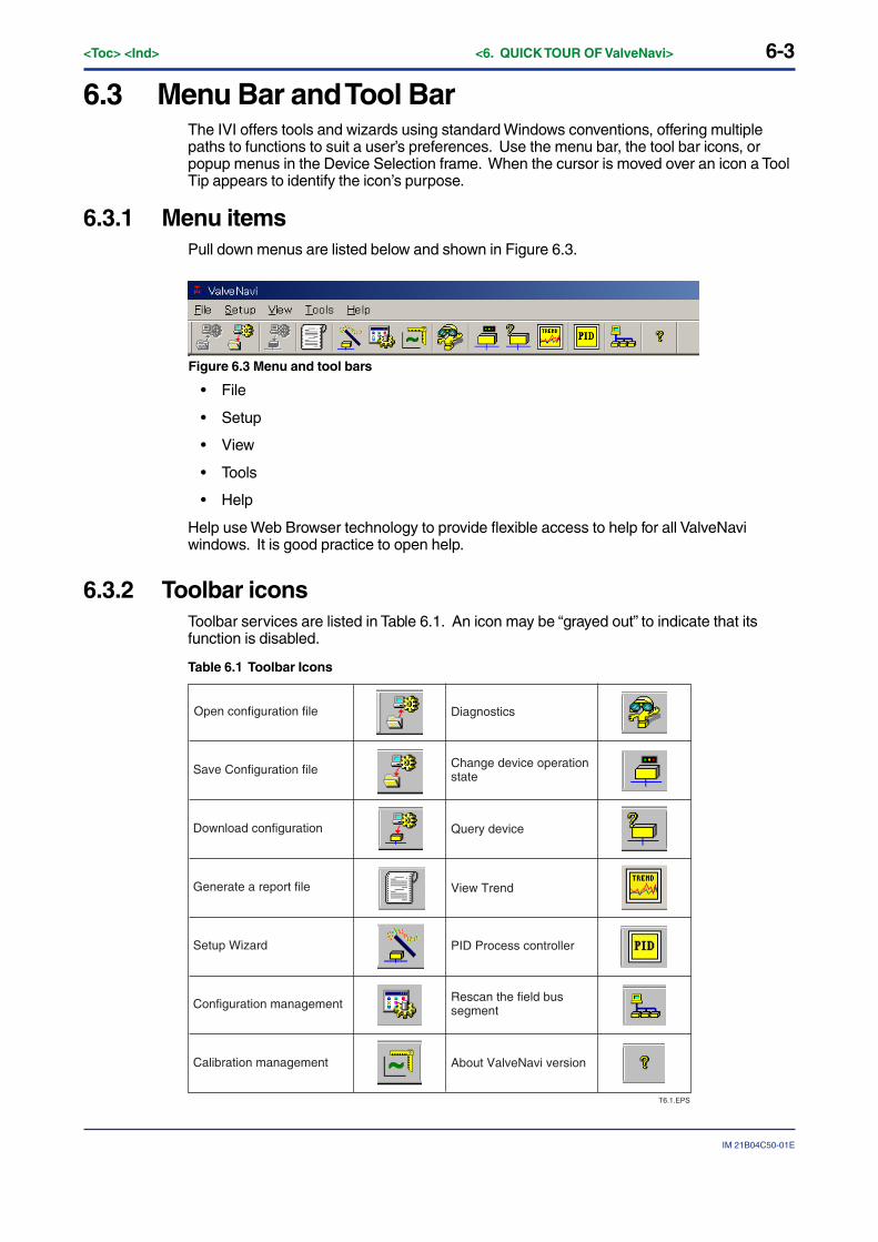
6.3 Menu Bar and Tool BarThe IVI offers tools and wizards using standard Windows conventions, offering multiplepaths to functions to suit a user’s preferences. Use the menu bar, the tool bar icons, orpopup menus in the Device Selection frame. When the cursor is moved over an icon a ToolTip appears to identify the icon’s purpose.
6.3.1 Menu itemsPull down menus are listed below and shown in Figure 6.3.
Figure 6.3 Menu and tool bars
• File
• Setup
• View
• Tools
• Help
Help use Web Browser technology to provide flexible access to help for all ValveNaviwindows. It is good practice to open help.
6.3.2 Toolbar iconsToolbar services are listed in Table 6.1. An icon may be “grayed out” to indicate that itsfunction is disabled.
Table 6.1 Toolbar Icons
Diagnostics
Change device operation state
Query device
View Trend
PID Process controller
Rescan the field bus segment
About ValveNavi version
Open configuration file
Save Configuration file
Download configuration
Generate a report file
Setup Wizard
Configuration management
Calibration management
T6.1.EPS
6-4<Toc> <Ind> <6. QUICK TOUR OF ValveNavi>
IM 21B04C50-01E
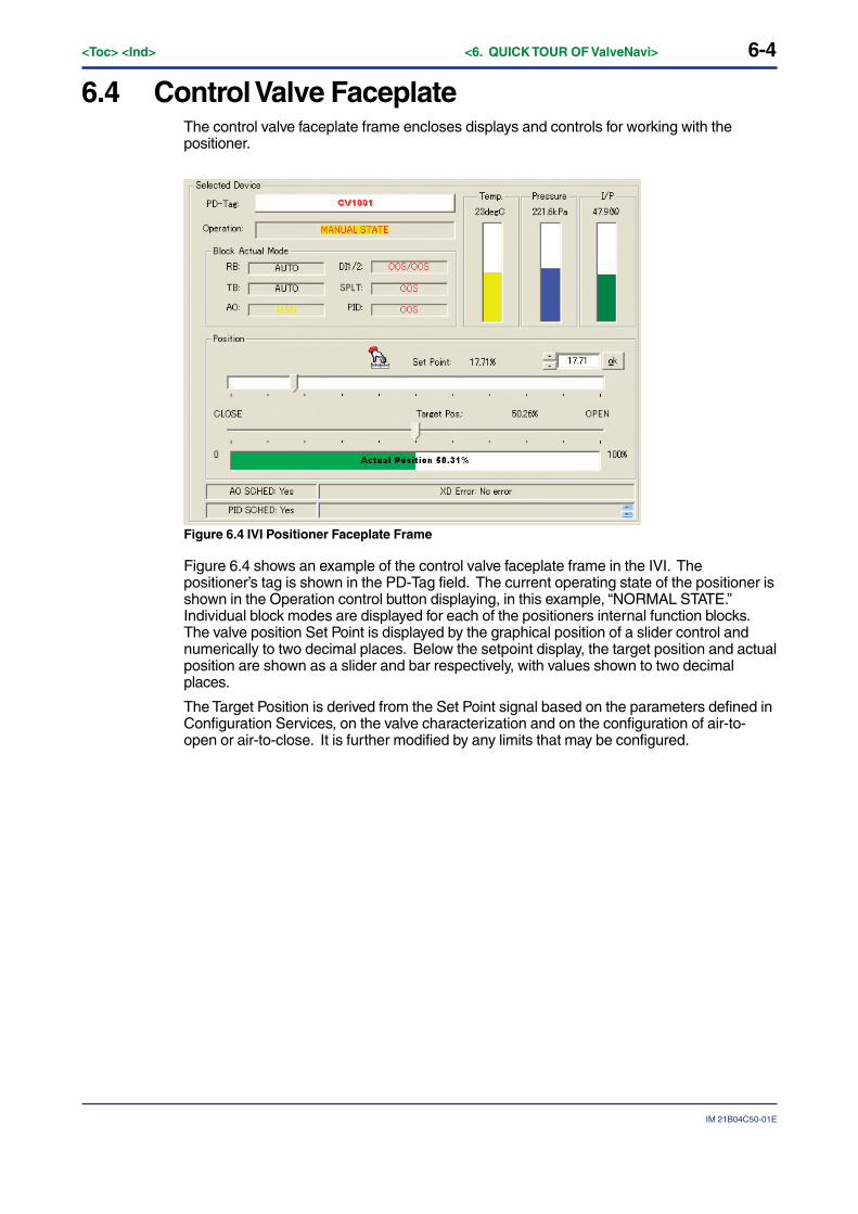
6.4 Control Valve FaceplateThe control valve faceplate frame encloses displays and controls for working with thepositioner.
Figure 6.4 IVI Positioner Faceplate Frame
Figure 6.4 shows an example of the control valve faceplate frame in the IVI. Thepositioner’s tag is shown in the PD-Tag field. The current operating state of the positioner isshown in the Operation control button displaying, in this example, “NORMAL STATE.”Individual block modes are displayed for each of the positioners internal function blocks.The valve position Set Point is displayed by the graphical position of a slider control andnumerically to two decimal places. Below the setpoint display, the target position and actualposition are shown as a slider and bar respectively, with values shown to two decimalplaces.
The Target Position is derived from the Set Point signal based on the parameters defined inConfiguration Services, on the valve characterization and on the configuration of air-to-open or air-to-close. It is further modified by any limits that may be configured.
6-5
IM 21B04C50-01E
<Toc> <Ind> <6. QUICK TOUR OF ValveNavi>
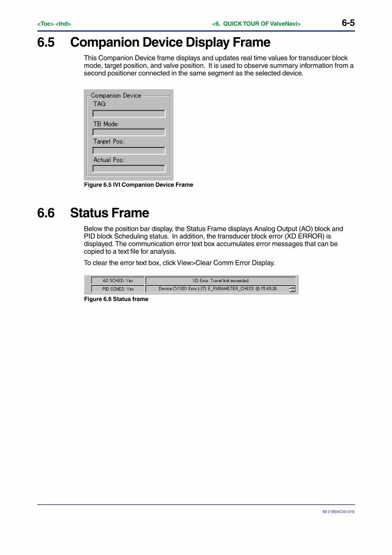
6.5 Companion Device Display FrameThis Companion Device frame displays and updates real time values for transducer blockmode, target position, and valve position. It is used to observe summary information from asecond positioner connected in the same segment as the selected device.
Figure 6.5 IVI Companion Device Frame
6.6 Status FrameBelow the position bar display, the Status Frame displays Analog Output (AO) block andPID block Scheduling status. In addition, the transducer block error (XD ERROR) isdisplayed. The communication error text box accumulates error messages that can becopied to a text file for analysis.
To clear the error text box, click View>Clear Comm Error Display.
Figure 6.6 Status frame

6-6<Toc> <Ind> <6. QUICK TOUR OF ValveNavi>
IM 21B04C50-01E
6.7 Accessing Services in ValveNaviServices in ValveNavi are accessed by three methods that are standard Windows tech-niques.
• By the Tools menu, after a device has been selected and opened, or
• By the toolbar icon, after a device has been selected and opened, or
• From the Device tree with a popup menu, by right clicking on the desired device.
6-7
IM 21B04C50-01E
<Toc> <Ind> <6. QUICK TOUR OF ValveNavi>
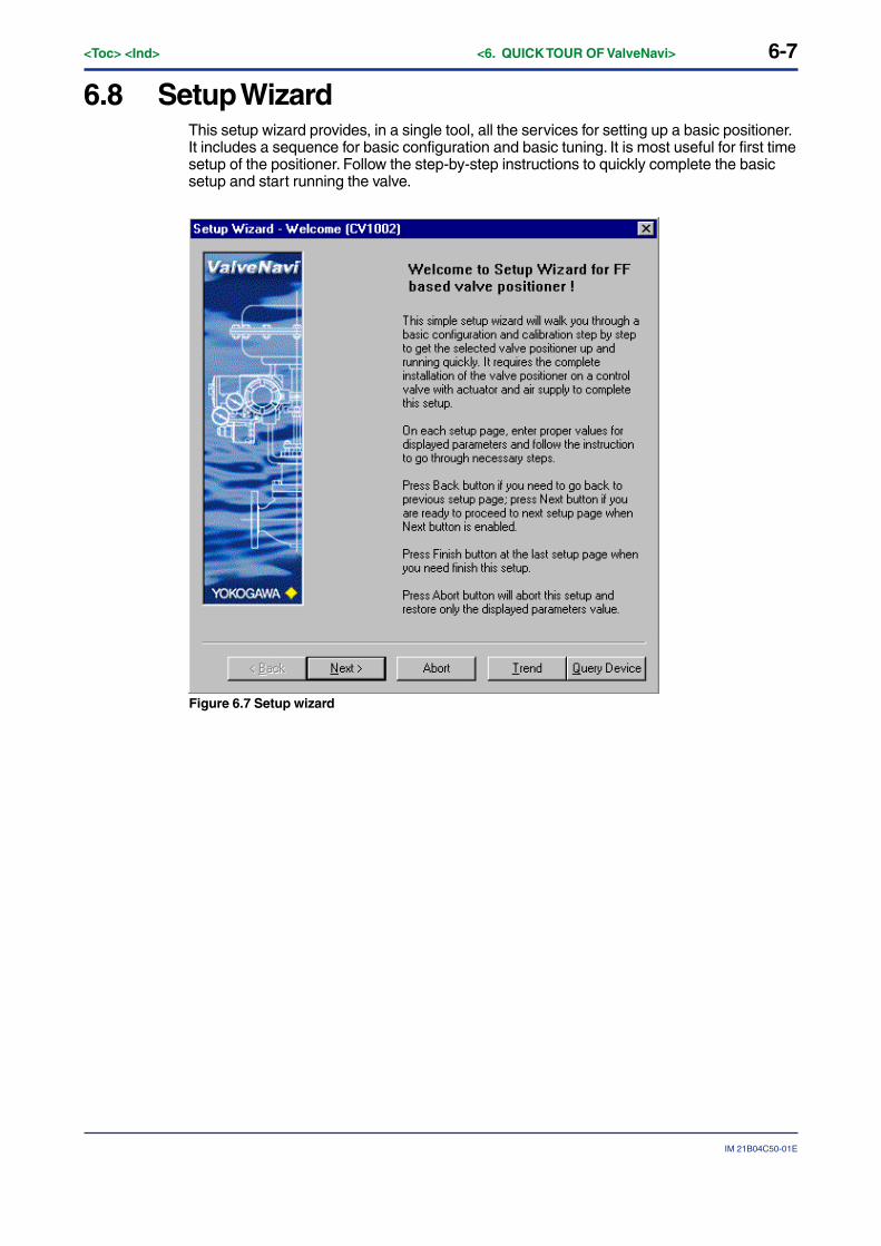
6.8 Setup WizardThis setup wizard provides, in a single tool, all the services for setting up a basic positioner.It includes a sequence for basic configuration and basic tuning. It is most useful for first timesetup of the positioner. Follow the step-by-step instructions to quickly complete the basicsetup and start running the valve.
Figure 6.7 Setup wizard

6-8<Toc> <Ind> <6. QUICK TOUR OF ValveNavi>
IM 21B04C50-01E
6.8.1 Actuator WizardThis is the setup page in the setup wizard to configure the valve actuator informationcontained in Transducer (TB) block. For a description of the parameters, refer to Actuator inthe Configuration window.
Figure 6.8 Actuator Wizard
6-9
IM 21B04C50-01E
<Toc> <Ind> <6. QUICK TOUR OF ValveNavi>
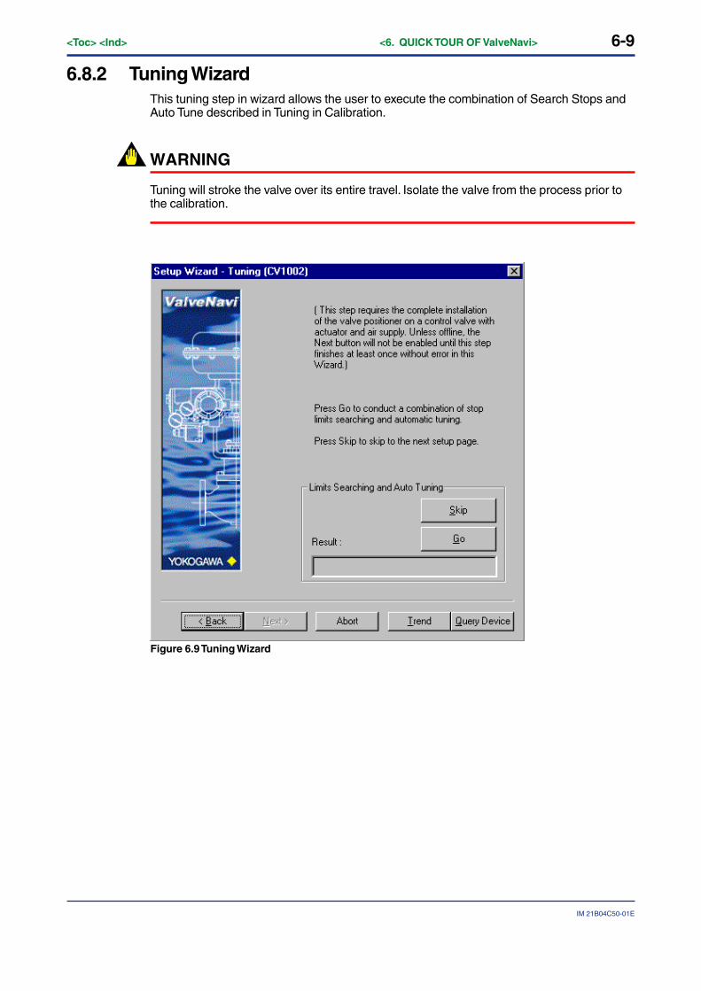
6.8.2 Tuning WizardThis tuning step in wizard allows the user to execute the combination of Search Stops andAuto Tune described in Tuning in Calibration.
WARNING
Tuning will stroke the valve over its entire travel. Isolate the valve from the process prior tothe calibration.
Figure 6.9 Tuning Wizard
6-10<Toc> <Ind> <6. QUICK TOUR OF ValveNavi>
IM 21B04C50-01E
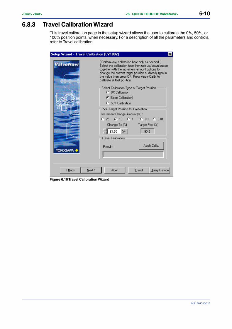
6.8.3 Travel Calibration WizardThis travel calibration page in the setup wizard allows the user to calibrate the 0%, 50%, or100% position points, when necessary. For a description of all the parameters and controls,refer to Travel calibration.
Figure 6.10 Travel Calibration Wizard
6-11
IM 21B04C50-01E
<Toc> <Ind> <6. QUICK TOUR OF ValveNavi>
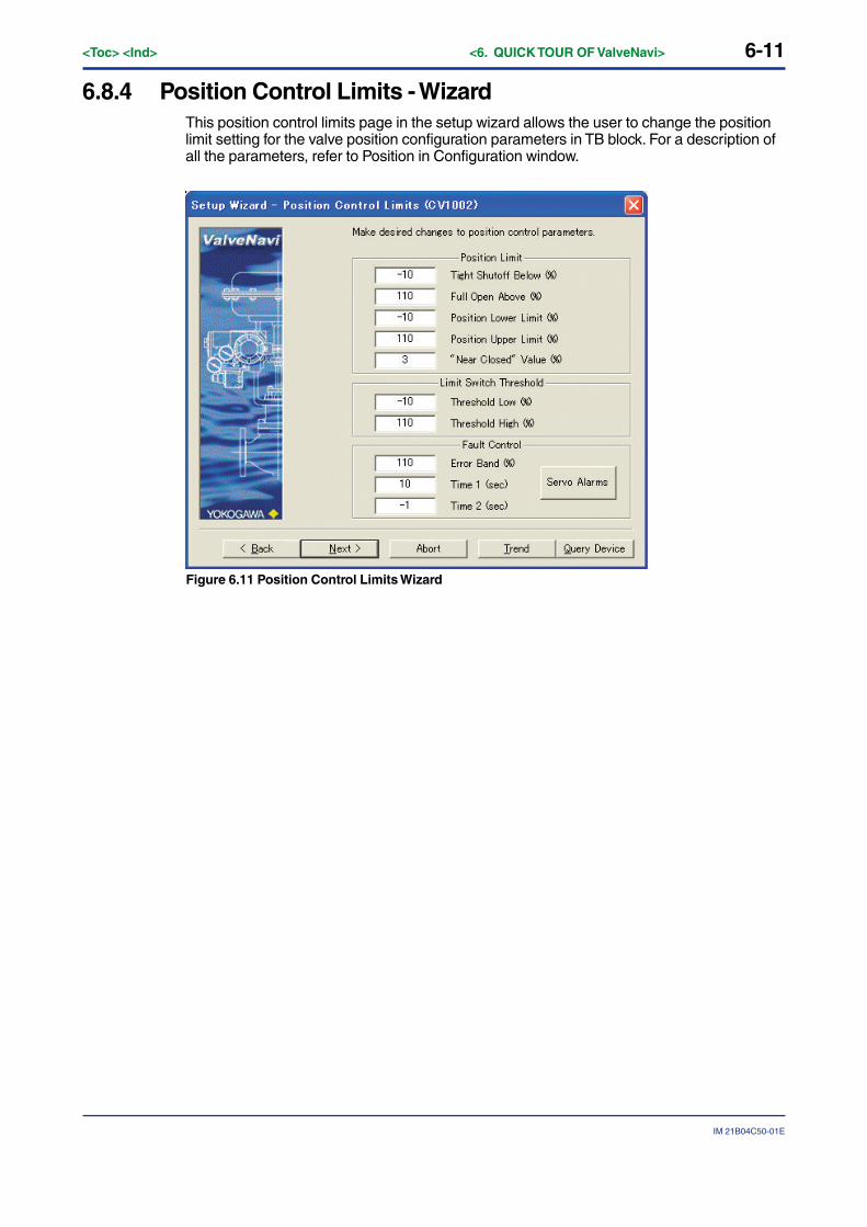
6.8.4 Position Control Limits - WizardThis position control limits page in the setup wizard allows the user to change the positionlimit setting for the valve position configuration parameters in TB block. For a description ofall the parameters, refer to Position in Configuration window.
Figure 6.11 Position Control Limits Wizard

6-12<Toc> <Ind> <6. QUICK TOUR OF ValveNavi>
IM 21B04C50-01E
6.8.5 Finish - Setup WizardThis is the final screen of the Setup Wizard that indicates that the basic setup is valid andthat provides a choice of Device Operation State before completing this setup. The Wizardis not completed until the Finish button is pressed.
Figure 6.12 Setup Wizard Finished
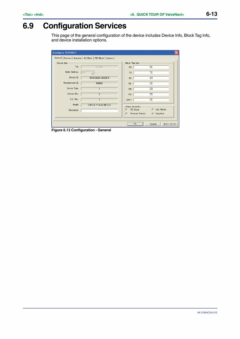
6-13
IM 21B04C50-01E
<Toc> <Ind> <6. QUICK TOUR OF ValveNavi>
6.9 Configuration ServicesThis page of the general configuration of the device includes Device Info, Block Tag Info,and device installation options.
Figure 6.13 Configuration - General
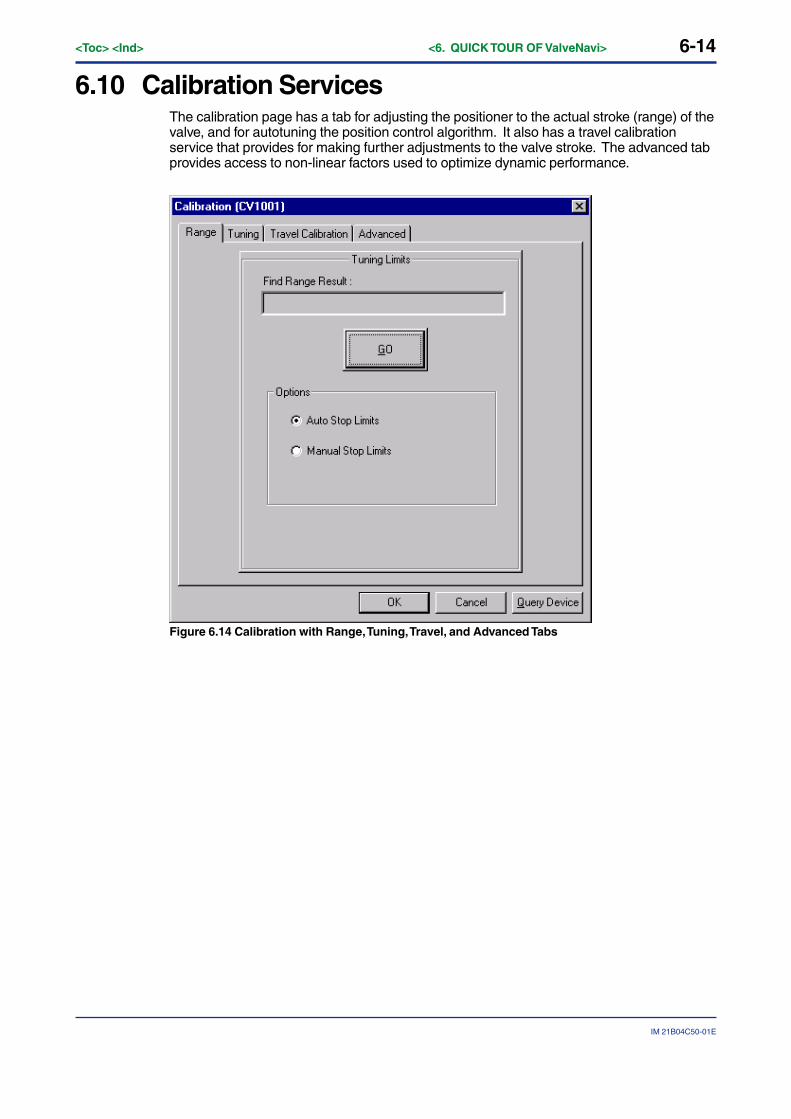
6-14<Toc> <Ind> <6. QUICK TOUR OF ValveNavi>
IM 21B04C50-01E
6.10 Calibration ServicesThe calibration page has a tab for adjusting the positioner to the actual stroke (range) of thevalve, and for autotuning the position control algorithm. It also has a travel calibrationservice that provides for making further adjustments to the valve stroke. The advanced tabprovides access to non-linear factors used to optimize dynamic performance.
Figure 6.14 Calibration with Range, Tuning, Travel, and Advanced Tabs
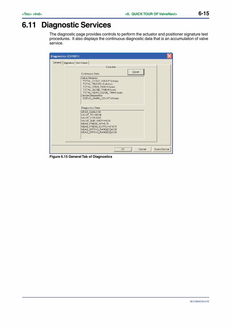
6-15
IM 21B04C50-01E
<Toc> <Ind> <6. QUICK TOUR OF ValveNavi>
6.11 Diagnostic ServicesThe diagnostic page provides controls to perform the actuator and positioner signature testprocedures. It also displays the continuous diagnostic data that is an accumulation of valveservice.
Figure 6.15 General Tab of Diagnostics
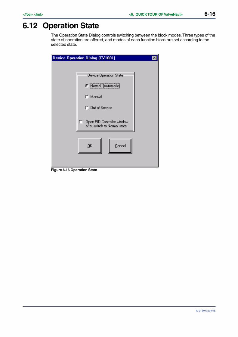
6-16<Toc> <Ind> <6. QUICK TOUR OF ValveNavi>
IM 21B04C50-01E
6.12 Operation StateThe Operation State Dialog controls switching between the block modes. Three types of thestate of operation are offered, and modes of each function block are set according to theselected state.
Figure 6.16 Operation State
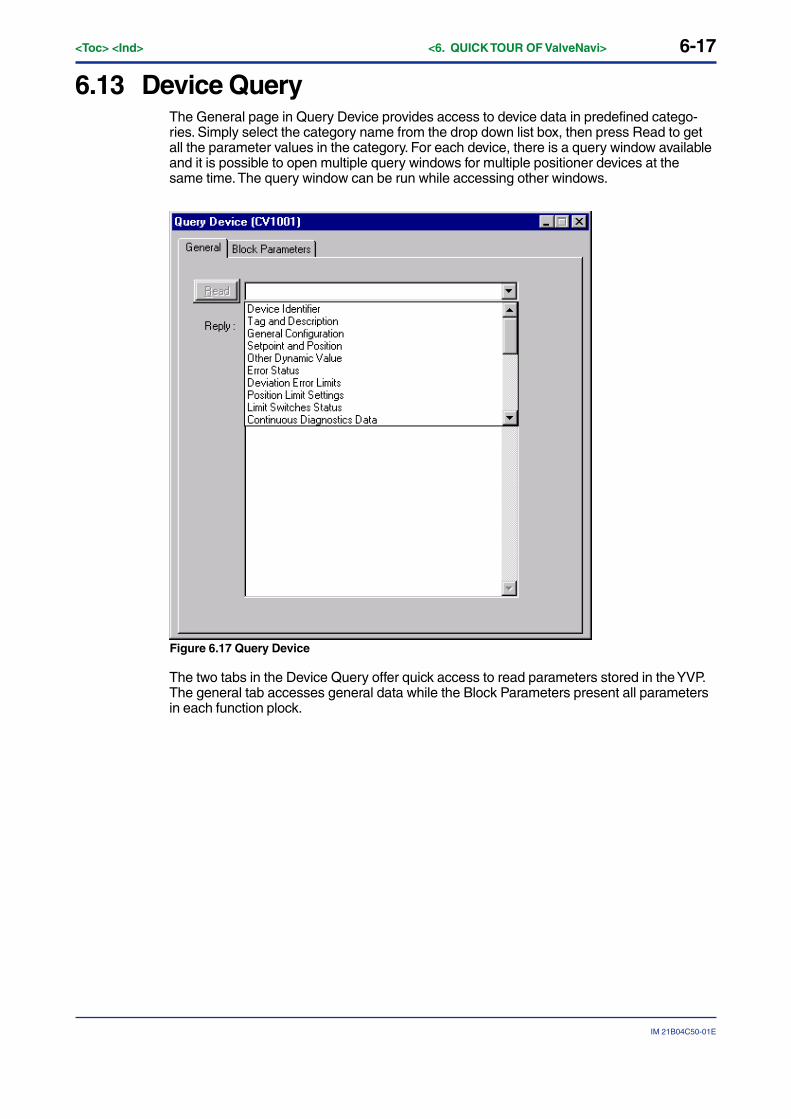
6-17
IM 21B04C50-01E
<Toc> <Ind> <6. QUICK TOUR OF ValveNavi>
6.13 Device QueryThe General page in Query Device provides access to device data in predefined catego-ries. Simply select the category name from the drop down list box, then press Read to getall the parameter values in the category. For each device, there is a query window availableand it is possible to open multiple query windows for multiple positioner devices at thesame time. The query window can be run while accessing other windows.
Figure 6.17 Query Device
The two tabs in the Device Query offer quick access to read parameters stored in the YVP.The general tab accesses general data while the Block Parameters present all parametersin each function plock.
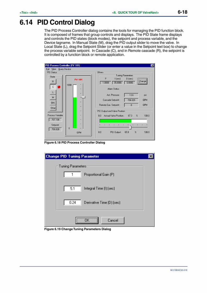
6-18<Toc> <Ind> <6. QUICK TOUR OF ValveNavi>
IM 21B04C50-01E
6.14 PID Control DialogThe PID Process Controller dialog contains the tools for managing the PID function block.It is composed of frames that group controls and displays. The PID State frame displaysand controls the PID states (block modes), the setpoint and process variable, and theDevice tagname. In Manual State (M), drag the PID output slider to move the valve. InLocal State (L), drag the Setpoint Slider (or enter a value in the Setpoint text box) to changethe process variable setpoint. In Cascade (C), and in Remote cascade (R), the setpoint iscontrolled by a function block or remote application.
Figure 6.18 PID Process Controller Dialog
Figure 6.19 Change Tuning Parameters Dialog
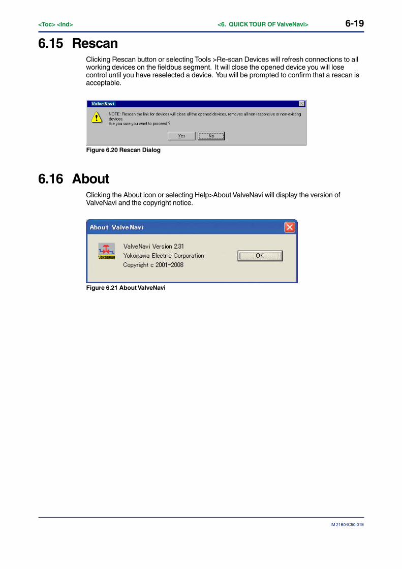
6-19
IM 21B04C50-01E
<Toc> <Ind> <6. QUICK TOUR OF ValveNavi>
6.15 RescanClicking Rescan button or selecting Tools >Re-scan Devices will refresh connections to allworking devices on the fieldbus segment. It will close the opened device you will losecontrol until you have reselected a device. You will be prompted to confirm that a rescan isacceptable.
Figure 6.20 Rescan Dialog
6.16 AboutClicking the About icon or selecting Help>About ValveNavi will display the version ofValveNavi and the copyright notice.
Figure 6.21 About ValveNavi
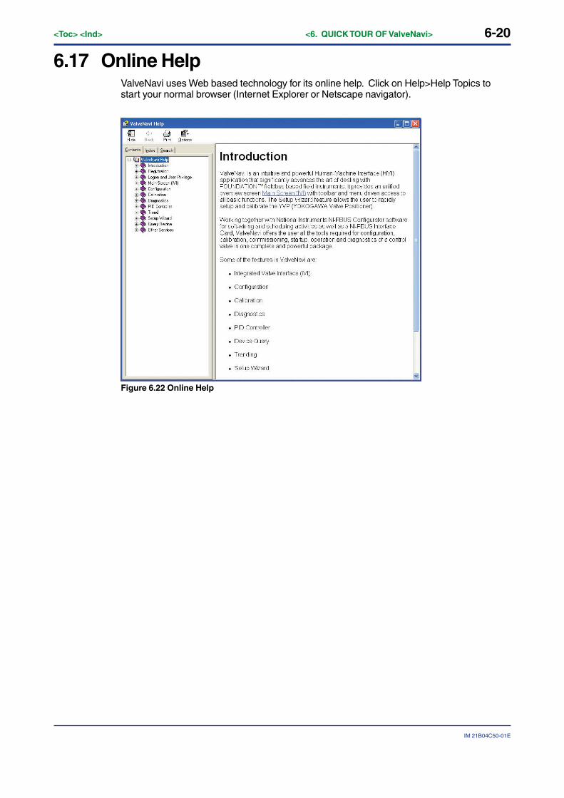
6-20<Toc> <Ind> <6. QUICK TOUR OF ValveNavi>
IM 21B04C50-01E
6.17 Online HelpValveNavi uses Web based technology for its online help. Click on Help>Help Topics tostart your normal browser (Internet Explorer or Netscape navigator).
Figure 6.22 Online Help

7-1
IM 21B04C50-01E
<Toc> <Ind> <7. INTEGRATED VALVE INTERFACE (IVI)>
7. INTEGRATED VALVE INTERFACE (IVI)The main application screen of ValveNavi is the Integrated Valve Interface (IVI) that isdisplayed after a successful logon (ValveNavi Logon). It monitors the operation stateand status of the valve. It provides access to all other services.
Figure 7.1 IVI
ValveNavi operation begins with the Integrated Valve Interface, IVI. The IVI is a windowwith a menu bar, a toolbar, a status bar, and frames containing displays and controls forfieldbus data objects. Each of the data objects relates to Foundation fieldbus parameters.The menu and tool bars provide access to services to work with files, devices and blocks.The status bar shows status of the fieldbus segment. The frames are used to group thedevice list tree, positioner data, Analog Output (AO) Block, and PID scheduling status, andblock modes, as well as device tag.
IVI displays all valve and positioner variables and provides access to services such asSetup Wizard, Configuration, Calibration, and Diagnostics tools. The information andcontrols for services are logically arranged in frames within IVI. From the IVI the user hassingle click access to the PID Controller interface. IVI displays and updates real time valuesfor valve position, valve setpoint, and actuator pressure, etc.
The IVI offers tools and wizards using standard Windows conventions, offering multiplepaths to functions to suit a user’s preferences. When the cursor is moved over an icon, aTool Tip appears to identify the icon’s purpose.

7-2<Toc> <Ind> <7. INTEGRATED VALVE INTERFACE (IVI)>
IM 21B04C50-01E
Menu items
Menu bar contains File, Setup, View, Tools, and Help menus.
Toolbar icons
Toolbar services are listed below, in the order of the icons shown on the Toolbar. While afunction is disabled its icon is “grayed out.”
Table 7.1 Toolbar Icons
Diagnostics
Change device operation state
Query device
View Trend
PID Process controller
Rescan the field bus segment
About ValveNavi version
Open configuration file
Save Configuration file
Download configuration
Generate a report file
Setup Wizard
Configuration management
Calibration management
T0701.EPS
The positioner’s tag is shown in the PD Tag field. The current operating state of thepositioner is shown the text box. Individual block modes are displaye for each of thepositioners internal function blocks. The valve position Set Point is displayed by the graphi-cal position of a slider and numerically to two decimal places. Below the setpoint display,the target position and actual position are shown as a slider and bar respectively, withvalues shown to two decimal places.
The Target Position is derived from the Set Point signal based on the parameters defined inConfiguration Services, as well as the characterization and the configuration of air-to-openor air-to-close. If linear characteristics and air-to-open are configured, without limits, theposition setpoint is equal to input signal expressed in percentage. When the configurationis nonlinear with limits, the incoming setpoint and the target position differ because theAnalog Output (AO) Block and Transducer (TB) Block re-compute the target to conform.
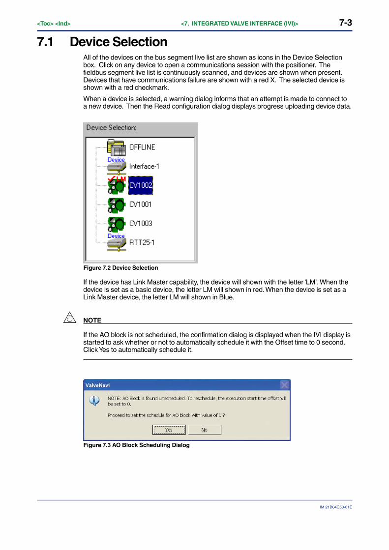
7-3
IM 21B04C50-01E
<Toc> <Ind> <7. INTEGRATED VALVE INTERFACE (IVI)>
7.1 Device SelectionAll of the devices on the bus segment live list are shown as icons in the Device Selectionbox. Click on any device to open a communications session with the positioner. Thefieldbus segment live list is continuously scanned, and devices are shown when present.Devices that have communications failure are shown with a red X. The selected device isshown with a red checkmark.
When a device is selected, a warning dialog informs that an attempt is made to connect toa new device. Then the Read configuration dialog displays progress uploading device data.
Figure 7.2 Device Selection
If the device has Link Master capability, the device will shown with the letter ‘LM’. When thedevice is set as a basic device, the letter LM will shown in red. When the device is set as aLink Master device, the letter LM will shown in Blue.
NOTE
If the AO block is not scheduled, the confirmation dialog is displayed when the IVI display isstarted to ask whether or not to automatically schedule it with the Offset time to 0 second.Click Yes to automatically schedule it.
Figure 7.3 AO Block Scheduling Dialog
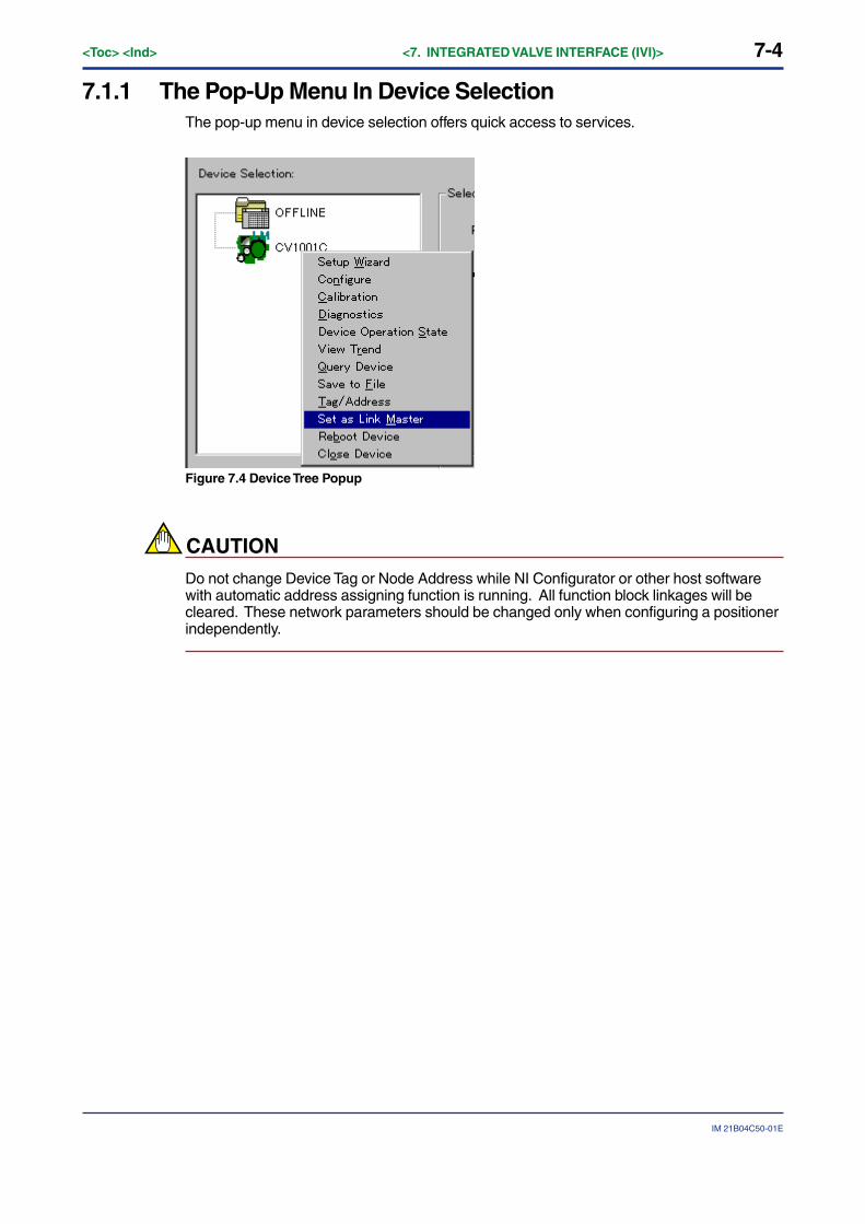
7-4<Toc> <Ind> <7. INTEGRATED VALVE INTERFACE (IVI)>
IM 21B04C50-01E
7.1.1 The Pop-Up Menu In Device SelectionThe pop-up menu in device selection offers quick access to services.
Figure 7.4 Device Tree Popup
CAUTION
Do not change Device Tag or Node Address while NI Configurator or other host softwarewith automatic address assigning function is running. All function block linkages will becleared. These network parameters should be changed only when configuring a positionerindependently.
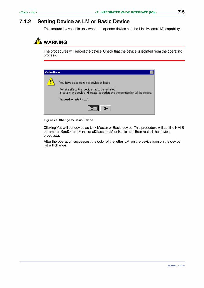
7-5
IM 21B04C50-01E
<Toc> <Ind> <7. INTEGRATED VALVE INTERFACE (IVI)>
7.1.2 Setting Device as LM or Basic DeviceThis feature is available only when the opened device has the Link Master(LM) capability.
WARNING
The procedures will reboot the device. Check that the device is isolated from the operatingprocess.
Figure 7.5 Change to Basic Device
Clicking Yes will set device as Link Master or Basic device. This procedure will set the NMIBparameter BootOperatFunctionalClass to LM or Basic first, then restart the deviceprocessor.
After the operation successes, the color of the letter ‘LM’ on the device icon on the devicelist will change.

7-6<Toc> <Ind> <7. INTEGRATED VALVE INTERFACE (IVI)>
IM 21B04C50-01E
7.2 Control Valve Faceplate
7.2.1 Selected DeviceThe Selected Device Frame provides a dedicated view for the selected device whichincludes device tag and operation state, blocks actual mode, valve position and setpoint,other status, and other parameters bar graph. It encloses displays and controls for workingwith the positioner and control valve.
Figure 7.6 Control Valve Faceplate with =% Characteristic
Figure 7.6 shows an example of the control valve faceplate frame in the IVI. Thepositioner’s tag is shown in the PD-Tag field. The current operating state of the positioner isshown in the Operation control button displaying. Individual block modes are displayed foreach of the positioners internal function blocks. The valve position Set Point is displayed bythe graphical position of a slider control and numerically to two decimal places. Below thesetpoint display, the target position and actual position are shown as a pointer and barrespectively, with values shown to two decimal places.
The Target Position is derived from the Set Point signal based on the calibration parametersdefined in Calibrate, on the valve characterization and on the configuration of air-to-open orair-to-close as defined in Configure. It is further modified by any limits that may beconfigured.
Each of the parameters displayed in the control faceplate dialog has a function block andparameter name (shown in the form of BLOCK.PARAMETER). These are listed in Table7.1.

7-7
IM 21B04C50-01E
<Toc> <Ind> <7. INTEGRATED VALVE INTERFACE (IVI)>
Table 7.1 IVI Faceplate Parameters
T0701.EPS
YVP output pressure for a Single Acting actuator or output pressure of out1 for a Double Acting actuator. Blue color.Scale = TB.SUPPLY_PRESSURE
Device Operation State may be one of the following:NORMAL (Automatic)MANUALOut Of ServiceIf no physical device is selected, it displays OFFLINE as the operation state.
This indicates the YVP’s tag.
Remarks
[PD.TAG]
[AO.OUT]
TB.FINAL_VALUE
TB.FINAL_POSITION_VALUE
TB.ELECT_TEMP
TB.OUT_PRESSURE
TB.SERVO_OUTPUT_SIGNAL
Parameter nameDisplay parameter
Operational State
Setpoint Signal
Target Position
Valve Position
Temperature
Pressure
I/P
Block modes
PD-Tag
Display type
Active control
Slider and XX.XX%
Bar and XX.XX%
Bar and XX deg
Bar and XX.XX Psi
Bar and XX.XX%
Device environmental temperature [-40, 85] Deg C or [-40, 185] Deg FColor: Yellow
Desired valve position before application of characterization and limits
A right clicking on this display can change the operation status.
Desired valve position as derived by the FF input value into the YVP.
This indicates valve stem or shaft position in percent of ranged travel.
Yellow: [0 to 20] %Green: [20 to 80] %Red: [80 to 100] %
AUTO,CAS: BlackMAN: YellowOOS: Red
Color coded Individual boxes
Block.MODE BLKBlock = RB, TB, AO, DI, or PID
7.2.2 Block Actual ModeThe following table lists the supported modes of the valve positioner for each block.
Table 7.2 Block Modes
Block Supported Modes
Resource Auto, O/S
Transducer Auto, O/S
AO RCas, Cas, Auto, Man, (LO), (IMAN), O/S
DI Auto, Man, O/S
OS Cas, Auto, (IMan), O/S
PID ROut, RCas, Cas, Auto, Man, (LO), (IMAN), O/S
7.2.3 PositionThis frame displays the valve position setpoint with the slider and a bargraph.The corresponding target position is displayed with a slider. The actual position is displayedwith a bargraph.
7.2.4 Other StatusIt displays Analog Output (AO) and PID block schedule status, transducer (XD) Errordescription, and communication error.

7-8<Toc> <Ind> <7. INTEGRATED VALVE INTERFACE (IVI)>
IM 21B04C50-01E
7.2.5 Temperature, Pressure, and I/P GraphsInternal temperature, output pressure (optional code/BP) and servo output to I/P moduleare displayed as bargraphs.
Click View > (Bar Name) to toggle the bar on or off.
7.3 Companion DeviceThe Companion Device frame provides a view of a device which is a companion to theselected device, such as a valve related to the selected valve. To select a companiondevice, there must be a focus device selected and viewed in the Selected Device frame.Pull down the View menu or right click a non-selected device to access the Select/Deselectas Companion dialog. Currently, the companion device is limited to the YVP.
Figure 7.7 Companion Device
● Tag
The physical device tag of the selected companion device.
● TB Mode
The actual mode of TB Block of the selected companion device.
● Target Position
The target valve position of the selected companion device.
● Actual Position
The actual valve position of the selected companion device.

8-1
IM 21B04C50-01E
<Toc> <Ind> <8. SETUP WIZARD>
8. SETUP WIZARDTo install and configure a YVP positioner the Setup Wizard is recommended. It combinesbasic calibration and tuning functions in a single sequence.
8.1 Introduction to Setup Wizard
Figure 8.1 Setup Wizard
This setup wizard provides, in a single tool, all the services for setting up a basic valvepositioner. It includes a sequence of wizards for basic configuration and basic tuning. It ismost useful for first-time setup of the positioner. Follow the step-by-step instructions in fivedialogs to complete the basic setup and to start running the valve.
Click Next to begin the setup with the Acuator Wizard.
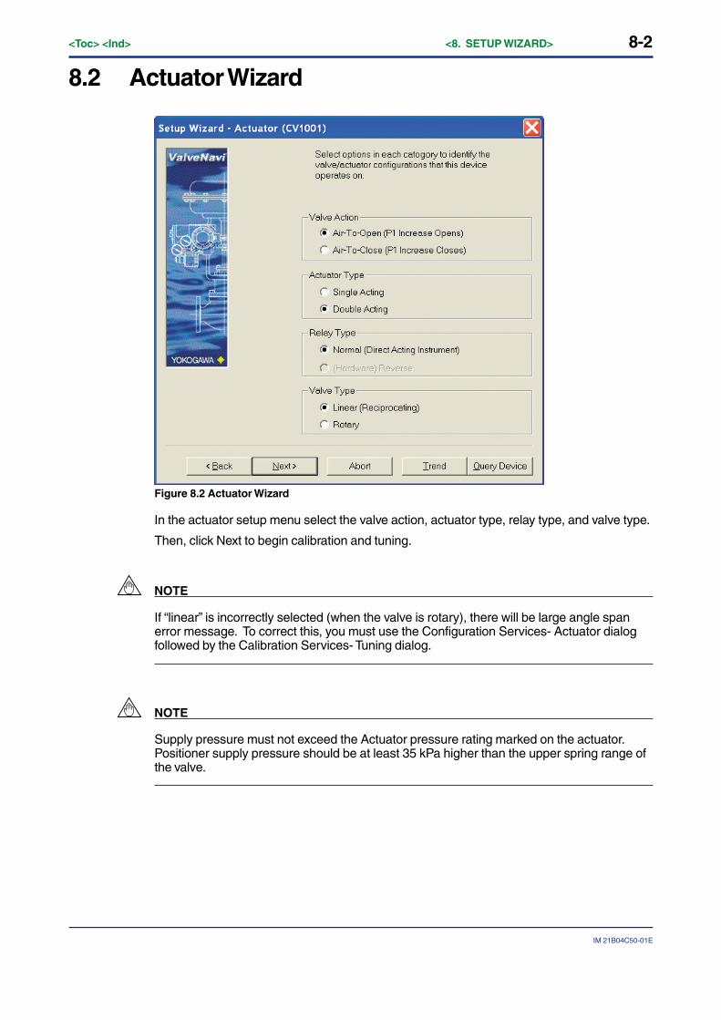
8-2<Toc> <Ind> <8. SETUP WIZARD>
IM 21B04C50-01E
8.2 Actuator Wizard
Figure 8.2 Actuator Wizard
In the actuator setup menu select the valve action, actuator type, relay type, and valve type.
Then, click Next to begin calibration and tuning.
NOTE
If “linear” is incorrectly selected (when the valve is rotary), there will be large angle spanerror message. To correct this, you must use the Configuration Services- Actuator dialogfollowed by the Calibration Services- Tuning dialog.
NOTE
Supply pressure must not exceed the Actuator pressure rating marked on the actuator.Positioner supply pressure should be at least 35 kPa higher than the upper spring range ofthe valve.
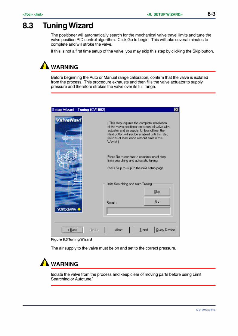
8-3
IM 21B04C50-01E
<Toc> <Ind> <8. SETUP WIZARD>
8.3 Tuning WizardThe positioner will automatically search for the mechanical valve travel limits and tune thevalve position PID control algorithm. Click Go to begin. This will take several minutes tocomplete and will stroke the valve.
If this is not a first time setup of the valve, you may skip this step by clicking the Skip button.
WARNING
Before beginning the Auto or Manual range calibration, confirm that the valve is isolatedfrom the process. This procedure exhausts and then fills the valve actuator to supplypressure and therefore strokes the valve over its full range.
Figure 8.3 Tuning Wizard
The air supply to the valve must be on and set to the correct pressure.
WARNING
Isolate the valve from the process and keep clear of moving parts before using LimitSearching or Autotune.”

8-4<Toc> <Ind> <8. SETUP WIZARD>
IM 21B04C50-01E
If Limit Searching and Auto Tuning is performed successfully, a tuning result dialog will beshown for user’s confirmation.
If Accept is clicked, the new servo parameters will apply to the system. Otherwise, theoriginal servo parameters will be restored to the device.
Double acting specific parameters are applicable only for double acting actuator type.
Figure 8.4 Tuning Result
When the mechanical limits have been found and the tuning is complete, the result isdisplayed (Figure 8.5).
Figure 8.5 Tuning Wizard Succeeded or Failed
If the self calibration and autotuning procedures are unsuccessful, there will be messagesshown as in Figure 8.6
Figure 8.6 Tuning Wizard Error/Warning Messages
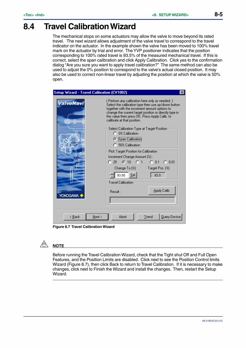
8-5
IM 21B04C50-01E
<Toc> <Ind> <8. SETUP WIZARD>
8.4 Travel Calibration WizardThe mechanical stops on some actuators may allow the valve to move beyond its ratedtravel. The next wizard allows adjustment of the valve travel to correspond to the travelindicator on the actuator. In the example shown the valve has been moved to 100% travelmark on the actuator by trial and error. The YVP positioner indicates that the positioncorresponding to 100% rated travel is 93.5% of the measured mechanical travel. If this iscorrect, select the span calibration and click Apply Calibration. Click yes to the confirmationdialog “Are you sure you want to apply travel calibration?” The same method can also beused to adjust the 0% position to correspond to the valve’s actual closed position. It mayalso be used to correct non-linear travel by adjusting the position at which the valve is 50%open.
Figure 8.7 Travel Calibration Wizard
NOTE
Before running the Travel Calibration Wizard, check that the Tight shut Off and Full OpenFeatures, and the Position Limits are disabled. Click next to see the Position Control limitsWizard (Figure 8.7), then click Back to return to Travel Calibration. If it is necessary to makechanges, click next to Finish the Wizard and install the changes. Then, restart the SetupWizard.
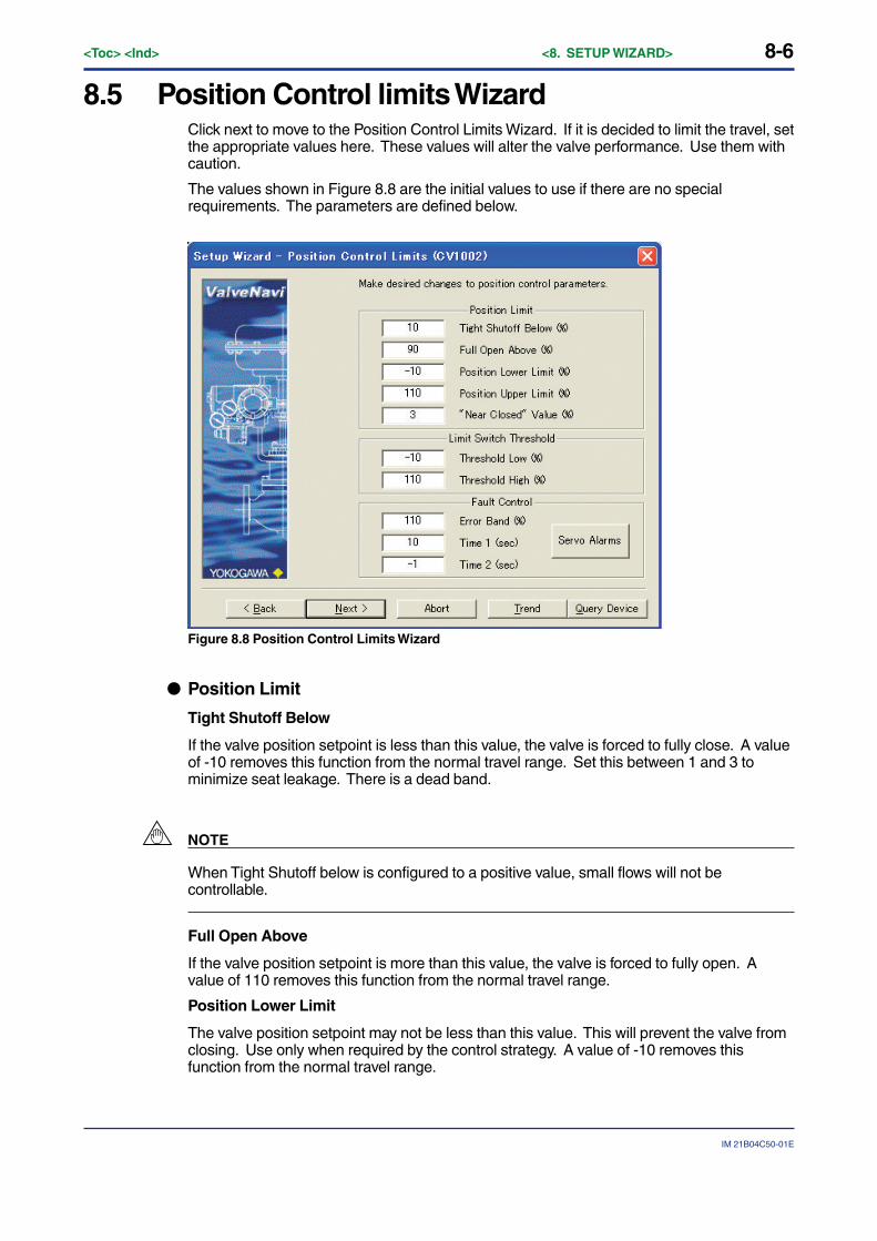
8-6<Toc> <Ind> <8. SETUP WIZARD>
IM 21B04C50-01E
8.5 Position Control limits WizardClick next to move to the Position Control Limits Wizard. If it is decided to limit the travel, setthe appropriate values here. These values will alter the valve performance. Use them withcaution.
The values shown in Figure 8.8 are the initial values to use if there are no specialrequirements. The parameters are defined below.
Figure 8.8 Position Control Limits Wizard
● Position Limit
Tight Shutoff Below
If the valve position setpoint is less than this value, the valve is forced to fully close. A valueof -10 removes this function from the normal travel range. Set this between 1 and 3 tominimize seat leakage. There is a dead band.
NOTE
When Tight Shutoff below is configured to a positive value, small flows will not becontrollable.
Full Open Above
If the valve position setpoint is more than this value, the valve is forced to fully open. Avalue of 110 removes this function from the normal travel range.
Position Lower Limit
The valve position setpoint may not be less than this value. This will prevent the valve fromclosing. Use only when required by the control strategy. A value of -10 removes thisfunction from the normal travel range.
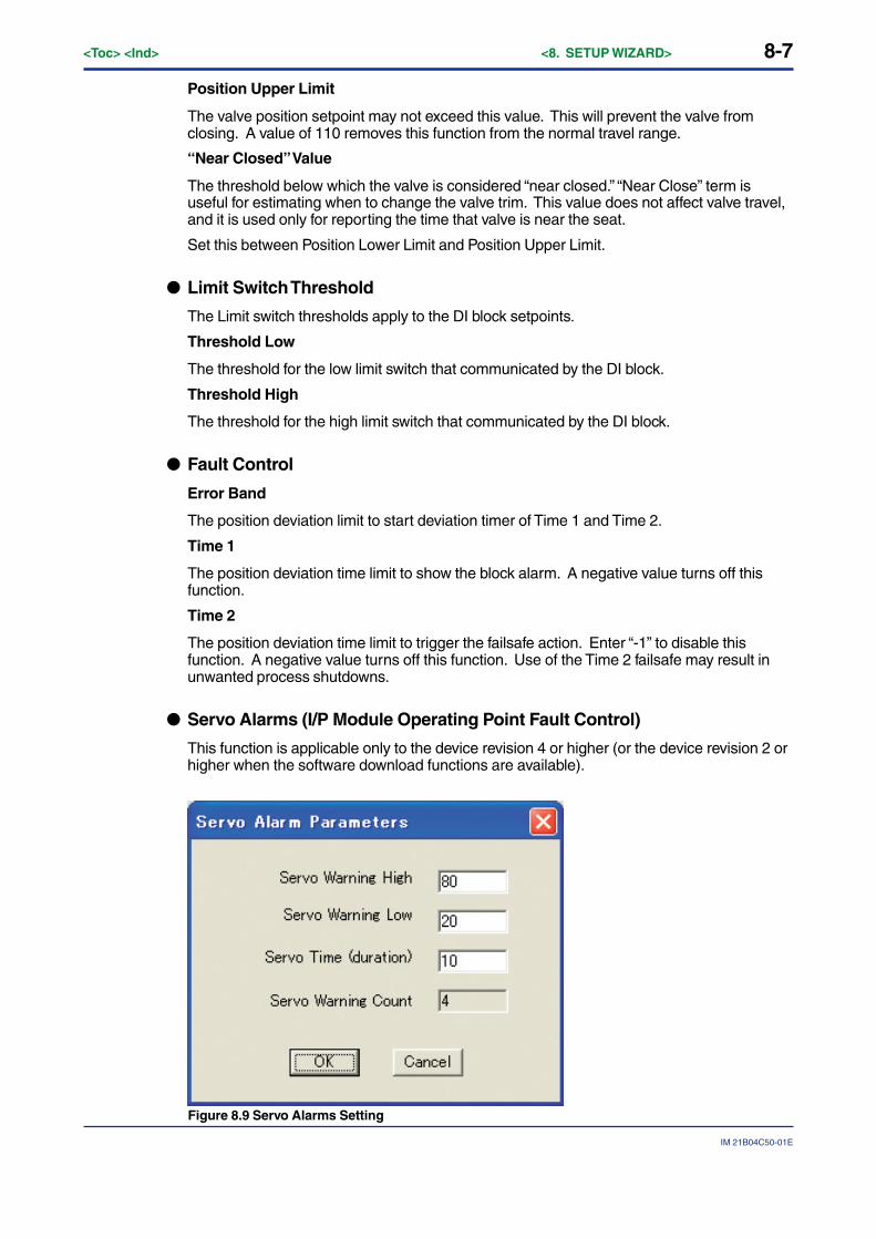
8-7
IM 21B04C50-01E
<Toc> <Ind> <8. SETUP WIZARD>
Position Upper Limit
The valve position setpoint may not exceed this value. This will prevent the valve fromclosing. A value of 110 removes this function from the normal travel range.
“Near Closed” Value
The threshold below which the valve is considered “near closed.” “Near Close” term isuseful for estimating when to change the valve trim. This value does not affect valve travel,and it is used only for reporting the time that valve is near the seat.
Set this between Position Lower Limit and Position Upper Limit.
● Limit Switch Threshold
The Limit switch thresholds apply to the DI block setpoints.
Threshold Low
The threshold for the low limit switch that communicated by the DI block.
Threshold High
The threshold for the high limit switch that communicated by the DI block.
● Fault Control
Error Band
The position deviation limit to start deviation timer of Time 1 and Time 2.
Time 1
The position deviation time limit to show the block alarm. A negative value turns off thisfunction.
Time 2
The position deviation time limit to trigger the failsafe action. Enter “-1” to disable thisfunction. A negative value turns off this function. Use of the Time 2 failsafe may result inunwanted process shutdowns.
● Servo Alarms (I/P Module Operating Point Fault Control)
This function is applicable only to the device revision 4 or higher (or the device revision 2 orhigher when the software download functions are available).
Figure 8.9 Servo Alarms Setting

8-8<Toc> <Ind> <8. SETUP WIZARD>
IM 21B04C50-01E
Servo Warning High
If the operating point of the I/P module is more than this value, the timer that measures thetime after the I/P module operating point error starts.
Servo Warning Low
If the operating point of the I/P module is less than this value, the timer that measures thetime after the I/P module operating point error starts. Input a value that is less than that forServo Warning High.
Servo Time (duration)
If the duration in which the I/P module operating point is out of the range from Servo Warn-ing Low to Servo Warning High reaches this set time, block alarm “Servo output drift warn-ing” is generated. If the duration in which the I/P module operating point is less than 10% ormore than 90% of the range reaches this set value, block alarm “Severe servo output drift”is generated. A negative value turns off these I/P module operating point warning detectionfunctions.
Servo Warning Count
Number of times of generation of block alarm “Servo output drift warning.”
To reset servo warning count to zero can be performed from General tab of Diagnostics.
8.6 Finish-Setup WizardThis is the final screen of the Setup Wizard that indicates that the basic setup is valid andthat provides a choice of Device Operation State before completing this setup. The Wizardis not completed until the Finish button is pressed.
Figure 8.10 Setup Wizard Finished
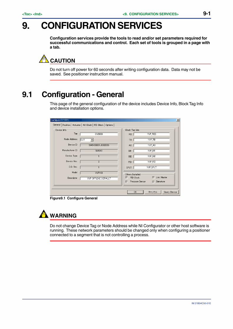
9-1
IM 21B04C50-01E
<Toc> <Ind> <9. CONFIGURATION SERVICES>
9. CONFIGURATION SERVICESConfiguration services provide the tools to read and/or set parameters required forsuccessful communications and control. Each set of tools is grouped in a page witha tab.
CAUTION
Do not turn off power for 60 seconds after writing configuration data. Data may not besaved. See positioner instruction manual.
9.1 Configuration - GeneralThis page of the general configuration of the device includes Device Info, Block Tag Infoand device installation options.
Figure9.1 Configure General
WARNING
Do not change Device Tag or Node Address while NI Configurator or other host software isrunning. These network parameters should be changed only when configuring a positionerconnected to a segment that is not controlling a process.
9-2<Toc> <Ind> <9. CONFIGURATION SERVICES>
IM 21B04C50-01E
9.1.1 Device Info
● Tag
The physical device tag (PD-Tag). The device tag is defined in Foundation fieldbus as astring of maximum 32 characters. Make sure the tag is unique in the entire control network.When a device is selected, this field is grayed out for read only. Therefore, the access to thedevice tag change is handled in Main Screen (IVI) by selecting the Setup menu or by rightclicking the device icon in Device Selection.
● Node Address
The node address is the address of the physical device on the fieldbus segment. Thedevice address is defined in Foundation Fieldbus as a value between 1 and 255. Makesure the address is unique in the segment. When a device is selected, this field is grayedout for read only. Therefore, the access to the device address change is handled in MainScreen (IVI) by selecting the Tools menu or by right clicking the device icon in DeviceSelection.
● Device ID
The device ID number consists of manufacturer id number, device number, and devicemodel related number. It is unique in all the devices among manufacturers and read only.
● Manufacturer ID
The 6 digits number of the device manufacturer ID is assigned by the Fieldbus Foundationand is read-only.
● Device Type
The type of the device is read only.
● Device Rev.
The revision of the device is read only.
● D. D. Rev.
The revision of the Device Description is read only.
● Model
The model of the device is read only.
● Descriptor
User may use this field for a description of the device or for memo.
9-3
IM 21B04C50-01E
<Toc> <Ind> <9. CONFIGURATION SERVICES>
9.1.2 Block Tag InfoEach block is assigned a default tag-name that should be renamed by the user.
● RB
The tag of the resource block.
● TB
The tag of the transducer block.
● AO
The tag of the analog output block.
● DI1
The tag of the discrete input 1 block.
● DI2
The tag of the discrete input 2 block.
● PID
The tag of the PID block.
● SPLT
The tag of the output splitter block.
9.1.3 Others Installed
● PID Block
Checked when the device PID block is activated. Read only.
● Pressure Sensor
Checked when the device pressure sensor is installed. Read only.
● Link Master
Checked when the device link master function is equipped. Read only.
● Signature
Checked when the device signature option (/BP) is installed. Read only.
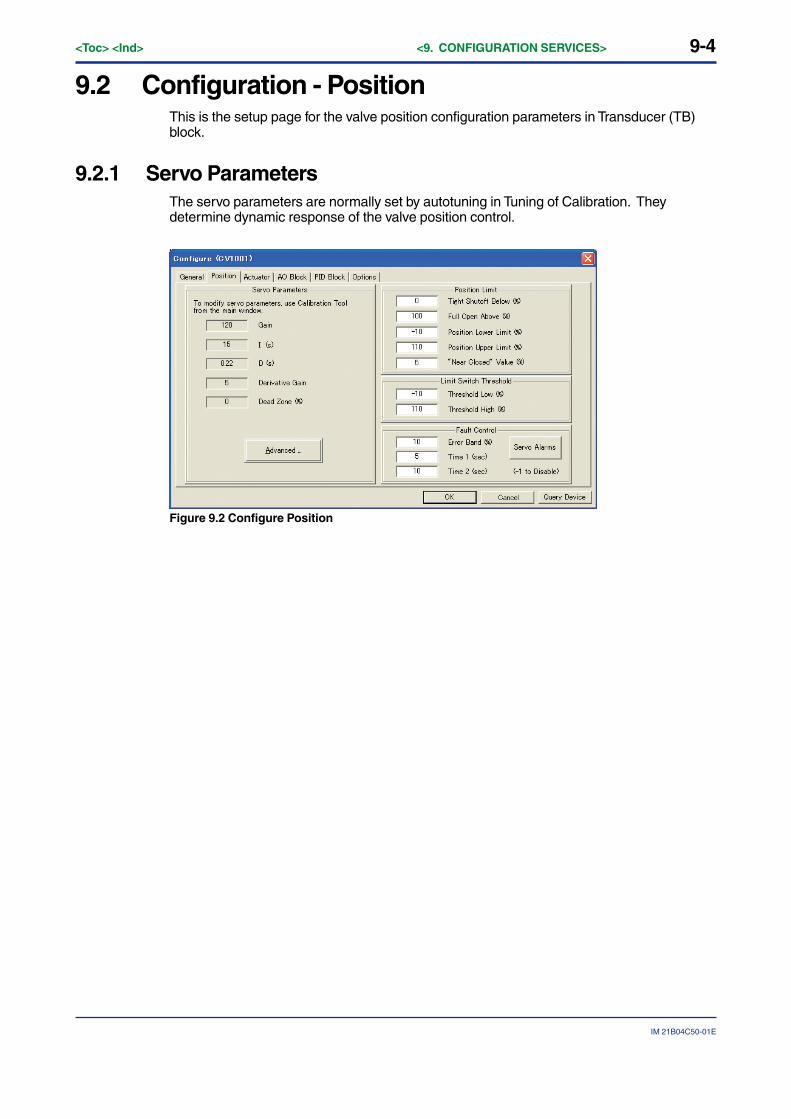
9-4<Toc> <Ind> <9. CONFIGURATION SERVICES>
IM 21B04C50-01E
9.2 Configuration - PositionThis is the setup page for the valve position configuration parameters in Transducer (TB)block.
9.2.1 Servo ParametersThe servo parameters are normally set by autotuning in Tuning of Calibration. Theydetermine dynamic response of the valve position control.
Figure 9.2 Configure Position
9-5
IM 21B04C50-01E
<Toc> <Ind> <9. CONFIGURATION SERVICES>
9.2.2 Position LimitThe Position Limits frame provides parameters that allow you to limit the valve, to force thevalve to close tightly or open fully at specified positions, to set the trip points of the limitswitches (DI Block). You can also activate a warning when a deviation lasts longer than theTime 1 or to force the valve to its failsafe position if the deviation lasts longer that time 2.
Since there is a dead zone of 1%, Tight Shut Off is disabled if the valve position setpoint is1% more than this value.
WARNING
Position Limit parameters are powerful tools to alter the valve performance to be non-linear.Use them with caution and only when the process requires special performance
● Tight Shutoff Below
If the valve target position is less than this value, the valve is forced to fully close. A value of-10 removes this function from the normal travel range, unless the calibration of valve travelhas been adjusted. Set this between 1 and 3 to minimize seat leakage. There is a deadband.
Since there is a dead zone of 1%, Full Open Above is disabled if the valve position setpointis 1% less than this value.
CAUTION
When Tight Shutoff below is configured to a positive value, small flows will not be control-lable.
● Full Open Above
If the valve target position is more than this value, the valve is forced to fully open. A valueof 110 removes this function from the normal travel range.
WARNING
Use of Full Open Above at values less than 110 may result in rapid increase in flow rate ifinput reaches this value. Use with extreme caution.
● Position Lower Limit
The valve target position may not be less than this value. This will prevent the valve fromclosing. Use only when required by the control strategy. A value of -10 removes thisfunction from the normal travel range.
● Position Upper Limit
The valve target position may not exceed this value. This will prevent the valve fromclosing. A value of 110 removes this function from the normal travel range.
● “Near Closed” Value
The threshold below which the valve is considered “near closed.” “Near Close” term isuseful for estimating when to change the valve trim. This value does not affect valve travel.It is used only for reporting the time that valve is near the seat.
9-6<Toc> <Ind> <9. CONFIGURATION SERVICES>
IM 21B04C50-01E
9.2.3 Limit Switch ThresholdThe Limit switch thresholds apply to the Discrete Input (DI) block setpoints.
● Threshold Low
The threshold for the low limit switch that communicated by the DI block.
● Threshold High
The threshold for the high limit switch that communicated by the DI block.
9.2.4 Fault Control
● Error Band
The position deviation limit to start deviation timer of Time 1 and Time 2.
Set this value to a value that is exceeded only in abnormal performance.
● Time 1
The position deviation time limit to show the block alarm. A negative value turns off thisfunction. Set this value greater than the stroking time.
● Time 2
The position deviation time limit to trigger the failsafe action. Enter “-1” to disable thisfunction. A negative value turns off this function. Use of the Time 2 failsafe may result inunwanted process shutdowns.
WARNING
Use the Time 2 failsafe only for a critical process that must be forced into its failsafe positionif the valve is unable to respond to its position setpoint after a reasonable time delay. Donot set the error band to a value that is too small. If Time 2 is used, it must be longer thanthe valve stroking time. A Time 2 value that is too small will result in nuisance failsafebehavior.
9.2.5 Servo Alarms (I/P Module Operating Point Fault Control)This function is applicable only to the device revision 4 or higher (or the device revision 2 orhigher when the software download functions are available).
● Servo Warning High
If the operating point of the I/P module is more than this value, the timer that measures thetime after the I/P module operating point error starts.
● Servo Warning Low
If the operating point of the I/P module is less than this value, the timer that measures thetime after the I/P module operating point error starts. Input a value that is the same as orless than that for Servo Warning High.

9-7
IM 21B04C50-01E
<Toc> <Ind> <9. CONFIGURATION SERVICES>
● Servo Time (duration)
If the duration in which the I/P module operating point is out of the range from Servo Warn-ing Low to Servo Warning High reaches this set time, block alarm “Servo output drift warn-ing” is generated. If the duration in which the I/P module operating point is less than 10% ormore than 90% reaches this set value, block alarm “Severe servo output drift” is generated.A negative value turns off these I/P module operating point warning detection functions.
● Servo Warning Count
Number of times of generation of block alarm “Servo output drift warning.”
To reset servo warning count to zero can be performed from General tab of Diagnostics.
9.2.6 AdvancedRefer to Advanced Position.
9.2.7 Configuration - Advanced PositionThis is the page for advanced position control parameters configuration contained inTransducer (TB) block. It is intended for technician use only. It lists here as read only. Tomodify the value of any parameter, go to Calibrate Advanced Position.
Figure 9.3 Advanced Servo Tuning Parameters
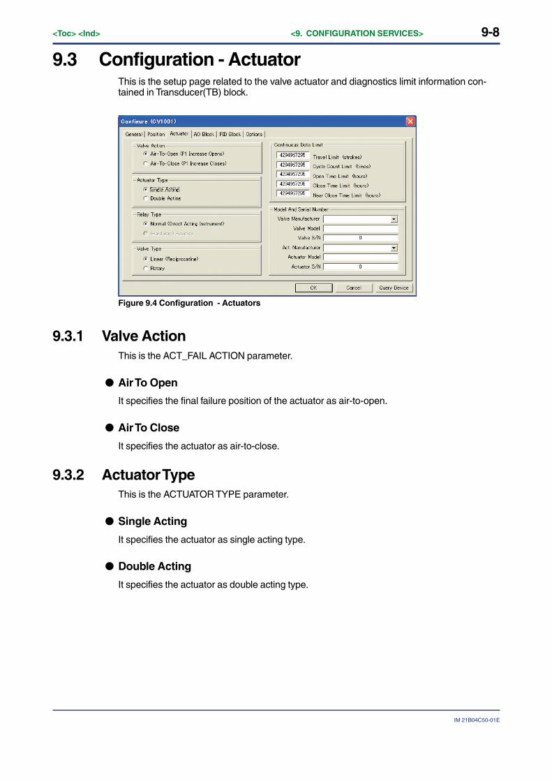
9-8<Toc> <Ind> <9. CONFIGURATION SERVICES>
IM 21B04C50-01E
9.3 Configuration - ActuatorThis is the setup page related to the valve actuator and diagnostics limit information con-tained in Transducer(TB) block.
Figure 9.4 Configuration - Actuators
9.3.1 Valve ActionThis is the ACT_FAIL ACTION parameter.
● Air To Open
It specifies the final failure position of the actuator as air-to-open.
● Air To Close
It specifies the actuator as air-to-close.
9.3.2 Actuator TypeThis is the ACTUATOR TYPE parameter.
● Single Acting
It specifies the actuator as single acting type.
● Double Acting
It specifies the actuator as double acting type.

9-9
IM 21B04C50-01E
<Toc> <Ind> <9. CONFIGURATION SERVICES>
9.3.3 Relay TypeThis is the RELAY TYPE parameter.
● Normal (Direct Acting Instrument)
It specifies the control relay as normal type.
● (Hardware) Reverse
It specifies the control relay as reverse type. This parameter is currently not available.
9.3.4 Valve TypeThis is the VALVE TYPE parameter.
● Linear (Reciprocating)
It specifies the valve as linear (reciprocating) type.
● Rotary
It specifies the valve as rotary type.
9.3.5 Continuous Data LimitThe following diagnostic parameters may be set to values useful to notify if service may beneeded. The maximum (default) value for each of the continuous data limits is 2^32(4294967295). Enter realistic values that represent useful maintenance life values.
● Travel Limit (strokes)
The total travel limit to show the block alarm.
● Cycle Count Limit (times)
The total cycle count limit to show the block alarm.
● Open Time Limit (hours)
The total valve open time limit to show the block alarm.
● Close Time Limit (hours)
The total valve close time limit to show the block alarm.
● Near Close Time Limit (hours)
The total valve near close time limit to show the block alarm.
9-10<Toc> <Ind> <9. CONFIGURATION SERVICES>
IM 21B04C50-01E
9.3.6 Model And Serial Number of ValveThe items in this section can be set and modified by users as a record of the informationrelated with the valve.
● Valve Manufacture
The valve manufacturer’s identification number as defined by the Fieldbus Foundation.
● Valve Model
The valve model number.
● Valve S/N
The valve serial number.
● Act. Manufacture
The actuator manufacturer’s identification number as defined by the Fieldbus Foundation.
● Actuator Model
The actuator model number.
● Actuator S/N
The actuator serial number.
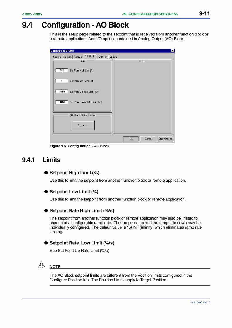
9-11
IM 21B04C50-01E
<Toc> <Ind> <9. CONFIGURATION SERVICES>
9.4 Configuration - AO BlockThis is the setup page related to the setpoint that is received from another function block ora remote application. And I/O option contained in Analog Output (AO) Block.
Figure 9.5 Configuration - AO Block
9.4.1 Limits
● Setpoint High Limit (%)
Use this to limit the setpoint from another function block or remote application.
● Setpoint Low Limit (%)
Use this to limit the setpoint from another function block or remote application.
● Setpoint Rate High Limit (%/s)
The setpoint from another function block or remote application may also be limited tochange at a configurable ramp rate. The ramp rate up and the ramp rate down may beindividually configured. The default value is 1.#INF (infinity) which eliminates ramp ratelimiting.
● Setpoint Rate Low Limit (%/s)
See Set Point Up Rate Limit (%/s)
NOTE
The AO Block setpoint limits are different from the Position limits configured in theConfigure Position tab. The Position Limits apply to Target Position.
9-12<Toc> <Ind> <9. CONFIGURATION SERVICES>
IM 21B04C50-01E
9.4.2 Configuration - AO Block OptionsThis setup page consists of both I/O Options and Status Options for the AO block. For eachparameter, it is enabled/disabled if it is checked/unchecked. IO_OPTS and STATUS_OPTSare parameters that control options about the AO block’s signal processing and modetransitions.
● SP Tracks PV if Man
Permits the setpoint to track the process variable when the target mode of the block is Man.
● SP Tracks PV if LO
Permits the setpoint to track the process variable when the actual mode of the block is LO.
● SP Tracks RCas or Cas if LO or Man (SP Track retained target)
In LO mode, SP is set to RCAS IN if target mode is Rcas. SP is set to CAS IN if targetmode is Cas.
● Increase to close
Indicates whether the output value should be inverted before it is communicated to the I/Ochannel of the TB. Inverts the SP signal before passing it to OUT.
● Fault State type
The output action to take when a fault occurs. (uncheck to freeze, check to go to a presetvalue). The initial preset value is 0. To change this parameter, use a configurator to changeFSTATE _VALUE in the AO block. Zero (0) is recommended for an air-to-open actuator and100 is recommended for an air to close actuator.
● Fault State restart
At a restart uses the same value that is preset for fault state type .
● Target to Man (if Fault State activated)
Set the target mode to Man, thus losing the original target, if Fault State is activated. Thislatches an output block into the manual mode. Sets the target mode to Man upon activationof the fault state.
● (Use) PV for BKCAL OUT
The BKCAL OUT value is normally the working SP. This option changes it to the PV. Setsthe value of PV in BKCAL OUT and RCAS OUT.
AO Status Options
● Propagate Fail Bkwd (Fault Backward)
Controls the handling of the value, data status and related alarm of BKCAL OUT andRCAS OUT.
When this option is selected, then the quality of the status of BKCAL OUT is set to Bad andits sub-status is set to sensor failure. The BKCAL OUT value is not affected. The AO blockdoes not alarm (but enables an upstream block to alarm).
When this option is not selected, then the quality of BKCAL OUT is set to Bad and its sub-status is set to non-specific. A block alarm is generated by the AO block.
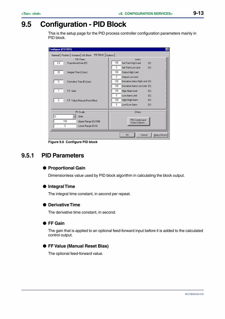
9-13
IM 21B04C50-01E
<Toc> <Ind> <9. CONFIGURATION SERVICES>
9.5 Configuration - PID BlockThis is the setup page for the PID process controller configuration parameters mainly inPID block.
Figure 9.6 Configure PID block
9.5.1 PID Parameters
● Proportional Gain
Dimensionless value used by PID block algorithm in calculating the block output.
● Integral Time
The integral time constant, in second per repeat.
● Derivative Time
The derivative time constant, in second.
● FF Gain
The gain that is applied to an optional feed-forward input before it is added to the calculatedcontrol output.
● FF Value (Manual Reset Bias)
The optional feed-forward value.
9-14<Toc> <Ind> <9. CONFIGURATION SERVICES>
IM 21B04C50-01E
9.5.2 Limits
● Set Point High Limit
The highest value that is allowed for the PID set point.
● Set Point Low Limit
The lowest value that is allowed for the PID set point.
● Output High Limit
The limit for the maximum PID output value.
● Output Low Limit
The limit for the minimum PID output value.
● Deviation Alarm High Limit
This is the parameter in PID block called DV_HI_LIM. It is the setting of the high deviationalarm limit.
● Deviation Alarm Low Limit
This is the parameter in PID block called DV_LO_LIM. It is the setting of the low deviationalarm limit.
● High Alarm Limit
This is the parameter in PID block called HI_LIM. It is the setting of the high alarm.
● Low Alarm Limit
This is the parameter in PID block called LO_LIM. It is the setting of the low alarm.
● High/High Alarm
This is the parameter in PID block called HI_HI_LIM. It is the setting of the high high alarm.
● Low/Low Alarm
This is the parameter in PID block called LO_LO_LIM. It is the setting of the low low alarm.
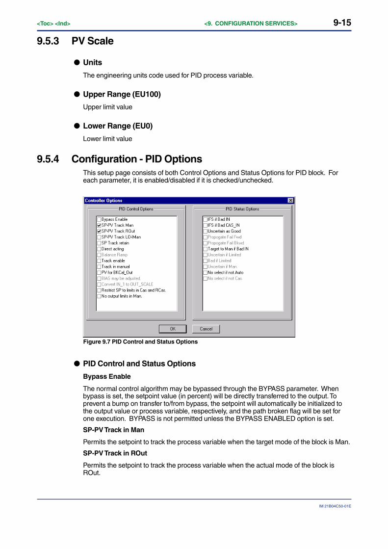
9-15
IM 21B04C50-01E
<Toc> <Ind> <9. CONFIGURATION SERVICES>
9.5.3 PV Scale
● Units
The engineering units code used for PID process variable.
● Upper Range (EU100)
Upper limit value
● Lower Range (EU0)
Lower limit value
9.5.4 Configuration - PID OptionsThis setup page consists of both Control Options and Status Options for PID block. Foreach parameter, it is enabled/disabled if it is checked/unchecked.
Figure 9.7 PID Control and Status Options
● PID Control and Status Options
Bypass Enable
The normal control algorithm may be bypassed through the BYPASS parameter. Whenbypass is set, the setpoint value (in percent) will be directly transferred to the output. Toprevent a bump on transfer to/from bypass, the setpoint will automatically be initialized tothe output value or process variable, respectively, and the path broken flag will be set forone execution. BYPASS is not permitted unless the BYPASS ENABLED option is set.
SP-PV Track in Man
Permits the setpoint to track the process variable when the target mode of the block is Man.
SP-PV Track in ROut
Permits the setpoint to track the process variable when the actual mode of the block isROut.
9-16<Toc> <Ind> <9. CONFIGURATION SERVICES>
IM 21B04C50-01E
SP-PV Track in LO or IMan
Permits the setpoint to track the process variable when the actual mode of the block is LOor IMan.
SP Track retained target
Permits the setpoint to track the RCas or Cas parameter based on the retained target modewhen the actual mode of the block is IMan, LO, Man, or ROut. When SP-PV track optionsare enabled, then SP Track retained target will have precedence in the selection of thevalue to track when the actual mode is Man, IMan, Rout, and LO.
Direct Acting
Defines the relationship between a change in PV and corresponding change in output.When Direct is selected, an increase in PV results in an increase in the output.
Track Enable
This enables the external tracking function. If true, the value in TRK_VAL will replace thevalue of OUT if TRK_IN_D becomes true and the target mode is not Man.
Track in Manual
This enables TRK_VAL to replace the value of OUT when the target mode is Man and TRK_IN_D is true. The actual mode will then be LO.
Use PV for BKCAL OUT
The BKCAL OUT and RCAS OUT values are normally the working SP. If this option isenabled, then the PV value will be used after the cascade is closed.
Restrict (Obey) SP limits if Cas or RCas
Normally the setpoint will not be restricted to the setpoint limits except when entered by ahuman interface device. However, if this option is selected, the setpoint will be restricted tothe setpoint absolute limits in the Cas and RCas modes.
No OUT limits in Manual
Do not apply OUT_HI_LIM or OUT_LO_LIM when target and actual modes are Man. Trustthe operator to do the right thing.
● PID Status Options
IFS if BAD IN
Set Initiate Fault State status in the OUT parameter if the status of the IN parameter is BAD.
IFS if BAD CAS IN
Set Initiate Fault State status in the OUT parameter if the status of the CAS _IN parameteris BAD.
Use Uncertain as Good
If the status of the IN parameter is Uncertain, treat it as Good. Otherwise, treat it as BAD.
Target to Manual if BAD IN
Set the target mode to Man if the status of the IN parameter is BAD. This latches a PIDblock into the Man state if the input ever goes bad.
No Select if not auto (Target to next permitted mode if BAD CAS IN)
Sets the target mode to next permitted mode if the target mode is CAS and the status ofCAS_IN falls to BAD.
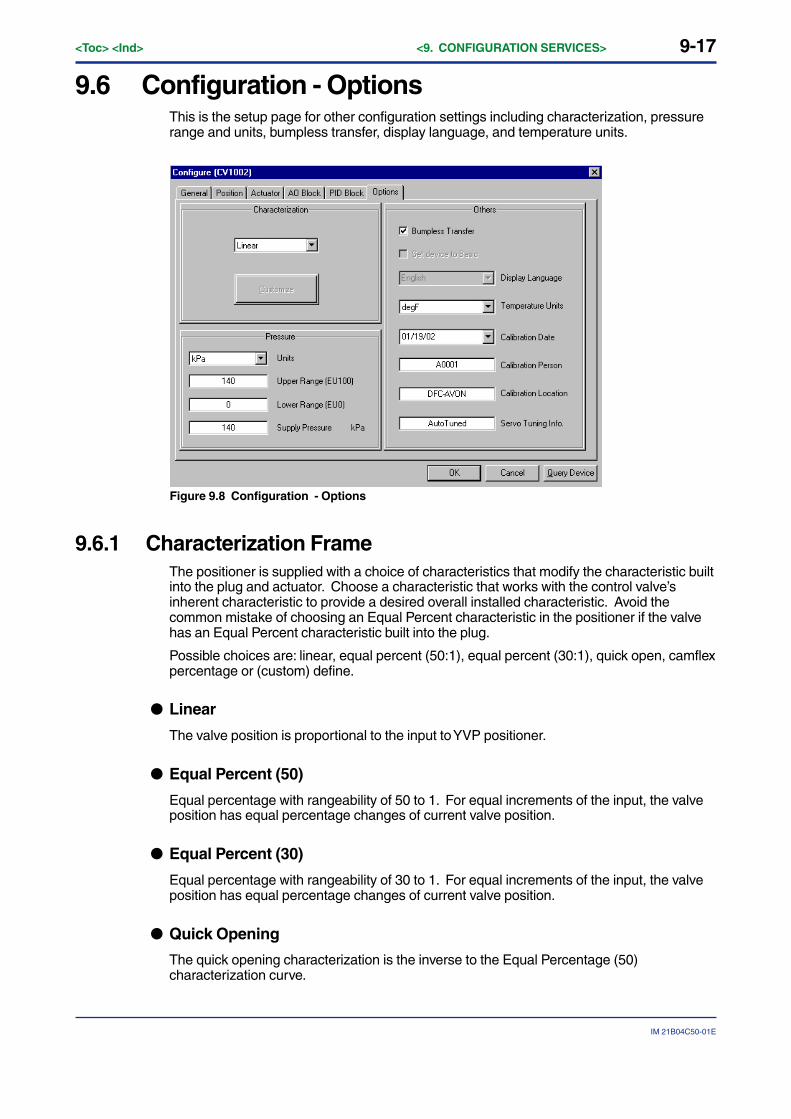
9-17
IM 21B04C50-01E
<Toc> <Ind> <9. CONFIGURATION SERVICES>
9.6 Configuration - OptionsThis is the setup page for other configuration settings including characterization, pressurerange and units, bumpless transfer, display language, and temperature units.
Figure 9.8 Configuration - Options
9.6.1 Characterization FrameThe positioner is supplied with a choice of characteristics that modify the characteristic builtinto the plug and actuator. Choose a characteristic that works with the control valve’sinherent characteristic to provide a desired overall installed characteristic. Avoid thecommon mistake of choosing an Equal Percent characteristic in the positioner if the valvehas an Equal Percent characteristic built into the plug.
Possible choices are: linear, equal percent (50:1), equal percent (30:1), quick open, camflexpercentage or (custom) define.
● Linear
The valve position is proportional to the input to YVP positioner.
● Equal Percent (50)
Equal percentage with rangeability of 50 to 1. For equal increments of the input, the valveposition has equal percentage changes of current valve position.
● Equal Percent (30)
Equal percentage with rangeability of 30 to 1. For equal increments of the input, the valveposition has equal percentage changes of current valve position.
● Quick Opening
The quick opening characterization is the inverse to the Equal Percentage (50)characterization curve.

9-18<Toc> <Ind> <9. CONFIGURATION SERVICES>
IM 21B04C50-01E
● Camflex Percentage
This function is used to equalize the flow rate characteristic with the Equal Percent charac-terization feature that is provided by mechanical positioners from Masoneilan.
● Define
A custom characterization defines the relationship between the input signal and the outputposition of the valve. Selecting this option will display an additional window where you canconfigure a characterization curve with 10 adjustable segments to fit your needs. The curvecan have up to 9 adjustable points and points in between are linearly interpolated.
Figure 9.9 Custom Characterization Dialog

9-19
IM 21B04C50-01E
<Toc> <Ind> <9. CONFIGURATION SERVICES>
● Custom Characterization Dialog
The Characterization Dialog lets the user define his own characterization. There are 9definable points for the valve position at 10% increments of position setpoint. Use themouse to drag the points on the curve or enter numerical values in the table to define thecharacterization.
To configure a custom characteristic curve, enter the values in the edit boxes at the bottomof the screen and press the Tab key. The graph is updated when the value is entered.
Alternatively, change the shape of the curve by clicking a point, holding the left mousebutton down, and dragging the cursor to a new position before releasing the mouse button.
Figure 9.10 Display mismatch for non-linear characteristic
After configuring the curve, click the OK button to accept the value and exit the Character-ization dialog, and click the OK button of Configure dialog, or click the Cancel button to exitwithout changing the values. To prevent a user from entering unreasonable points,ValveNavi will check the curve based on established rules and pop up a warning messagewhen the curve does not meet the rules. The characteristic points are saved in YVP with aresolution of five digits.
The unfinished curve in Figure 9.9 illustrates that the curve must be monotonic. (Eachpoint must be greater than the previous point.) To smoothly blend a point between itsadjacent points, right click the point. For all non-linear characteristics the set point will differfrom the target position.
Click OK to accept the custom characteristic.
NOTE
When the characteristic is linear, the displays of position setpoint and target valve positionwill all match. For all other (non-linear) characteristics the valve target position will differfrom the setpoint. See Figure 9.10
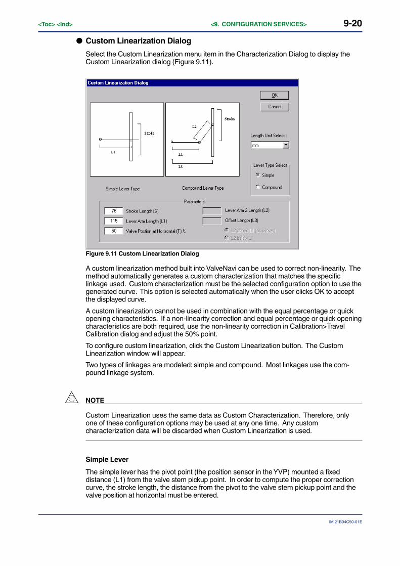
9-20<Toc> <Ind> <9. CONFIGURATION SERVICES>
IM 21B04C50-01E
● Custom Linearization Dialog
Select the Custom Linearization menu item in the Characterization Dialog to display theCustom Linearization dialog (Figure 9.11).
Figure 9.11 Custom Linearization Dialog
A custom linearization method built into ValveNavi can be used to correct non-linearity. Themethod automatically generates a custom characterization that matches the specificlinkage used. Custom characterization must be the selected configuration option to use thegenerated curve. This option is selected automatically when the user clicks OK to acceptthe displayed curve.
A custom linearization cannot be used in combination with the equal percentage or quickopening characteristics. If a non-linearity correction and equal percentage or quick openingcharacteristics are both required, use the non-linearity correction in Calibration>TravelCalibration dialog and adjust the 50% point.
To configure custom linearization, click the Custom Linearization button. The CustomLinearization window will appear.
Two types of linkages are modeled: simple and compound. Most linkages use the com-pound linkage system.
NOTE
Custom Linearization uses the same data as Custom Characterization. Therefore, onlyone of these configuration options may be used at any one time. Any customcharacterization data will be discarded when Custom Linearization is used.
Simple Lever
The simple lever has the pivot point (the position sensor in the YVP) mounted a fixeddistance (L1) from the valve stem pickup point. In order to compute the proper correctioncurve, the stroke length, the distance from the pivot to the valve stem pickup point and thevalve position at horizontal must be entered.
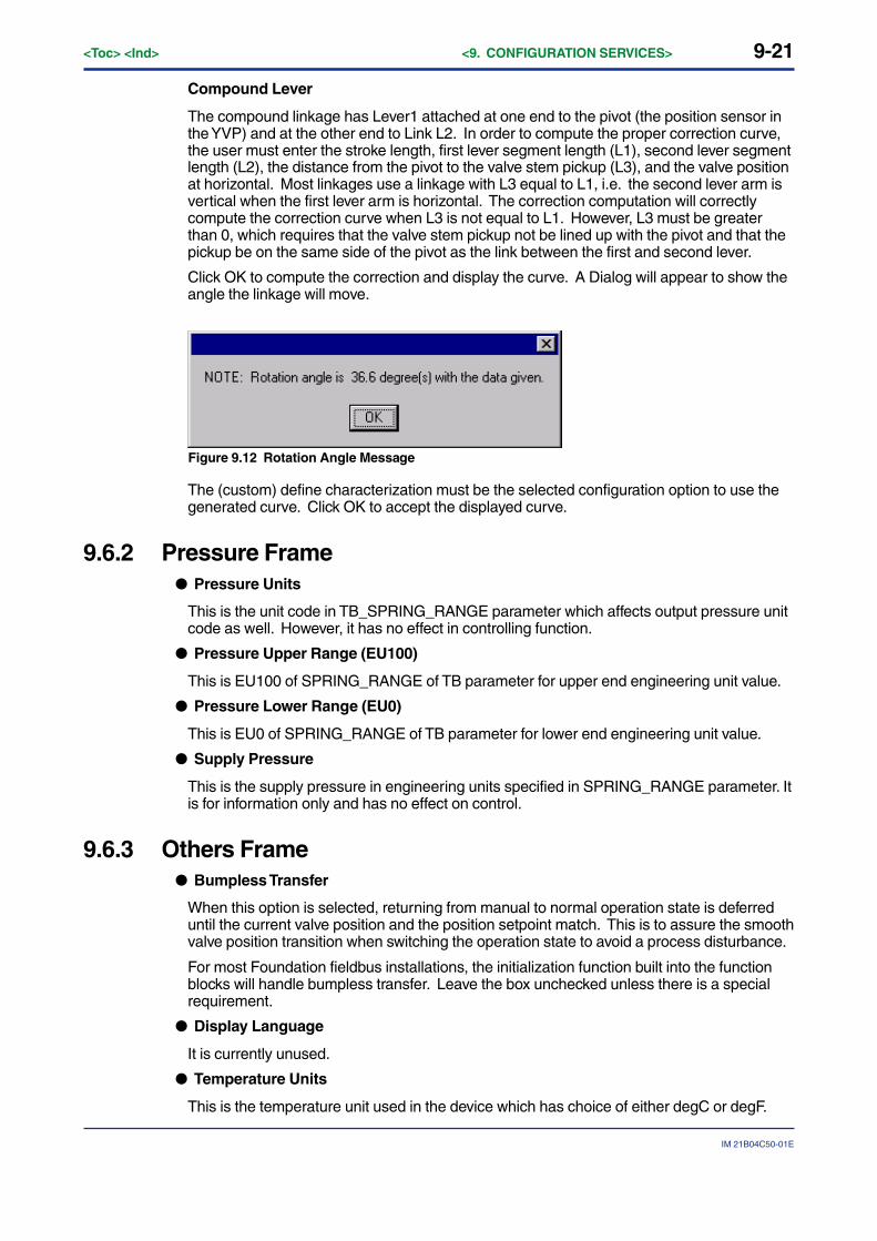
9-21
IM 21B04C50-01E
<Toc> <Ind> <9. CONFIGURATION SERVICES>
Compound Lever
The compound linkage has Lever1 attached at one end to the pivot (the position sensor inthe YVP) and at the other end to Link L2. In order to compute the proper correction curve,the user must enter the stroke length, first lever segment length (L1), second lever segmentlength (L2), the distance from the pivot to the valve stem pickup (L3), and the valve positionat horizontal. Most linkages use a linkage with L3 equal to L1, i.e. the second lever arm isvertical when the first lever arm is horizontal. The correction computation will correctlycompute the correction curve when L3 is not equal to L1. However, L3 must be greaterthan 0, which requires that the valve stem pickup not be lined up with the pivot and that thepickup be on the same side of the pivot as the link between the first and second lever.
Click OK to compute the correction and display the curve. A Dialog will appear to show theangle the linkage will move.
Figure 9.12 Rotation Angle Message
The (custom) define characterization must be the selected configuration option to use thegenerated curve. Click OK to accept the displayed curve.
9.6.2 Pressure Frame● Pressure Units
This is the unit code in TB_SPRING_RANGE parameter which affects output pressure unitcode as well. However, it has no effect in controlling function.
● Pressure Upper Range (EU100)
This is EU100 of SPRING_RANGE of TB parameter for upper end engineering unit value.
● Pressure Lower Range (EU0)
This is EU0 of SPRING_RANGE of TB parameter for lower end engineering unit value.
● Supply Pressure
This is the supply pressure in engineering units specified in SPRING_RANGE parameter. Itis for information only and has no effect on control.
9.6.3 Others Frame● Bumpless Transfer
When this option is selected, returning from manual to normal operation state is deferreduntil the current valve position and the position setpoint match. This is to assure the smoothvalve position transition when switching the operation state to avoid a process disturbance.
For most Foundation fieldbus installations, the initialization function built into the functionblocks will handle bumpless transfer. Leave the box unchecked unless there is a specialrequirement.
● Display Language
It is currently unused.
● Temperature Units
This is the temperature unit used in the device which has choice of either degC or degF.

10-1
IM 21B04C50-01E
<Toc> <Ind> <10. CALIBRATION SERVICES>
10. CALIBRATION SERVICESCalibration Services provide tools to set valve stroke, and to tune the dynamicparameters for control of position. Each set of tools is grouped in a tab.
10.1 Calibration - RangeTo calibrate the position sensor to match the actual valve travel, use the Auto Stop Limits orthe Manual Stop Limits function to search for the mechanical stop limits of the valve.
To check if the calibration is done properly, move the valve to the stops in the Main Screen(IVI) in manual operating state.
Figure 10.1 Range Calibration
WARNING
Range Calibration strokes the valve over its entire travel. Isolate the valve from the processprior to using the calibration procedure.
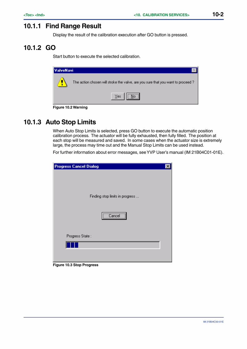
10-2<Toc> <Ind> <10. CALIBRATION SERVICES>
IM 21B04C50-01E
10.1.1 Find Range ResultDisplay the result of the calibration execution after GO button is pressed.
10.1.2 GOStart button to execute the selected calibration.
Figure 10.2 Warning
10.1.3 Auto Stop LimitsWhen Auto Stop Limits is selected, press GO button to execute the automatic positioncalibration process. The actuator will be fully exhausted, then fully filled. The position ateach stop will be measured and saved. In some cases when the actuator size is extremelylarge, the process may time out and the Manual Stop Limits can be used instead.
For further information about error messages, see YVP User’s manual (IM 21B04C01-01E).
Figure 10.3 Stop Progress
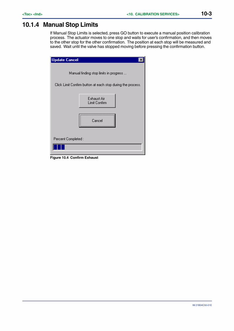
10-3
IM 21B04C50-01E
<Toc> <Ind> <10. CALIBRATION SERVICES>
10.1.4 Manual Stop LimitsIf Manual Stop Limits is selected, press GO button to execute a manual position calibrationprocess. The actuator moves to one stop and waits for user’s confirmation, and then movesto the other stop for the other confirmation. The position at each stop will be measured andsaved. Wait until the valve has stopped moving before pressing the confirmation button.
Figure 10.4 Confirm Exhaust
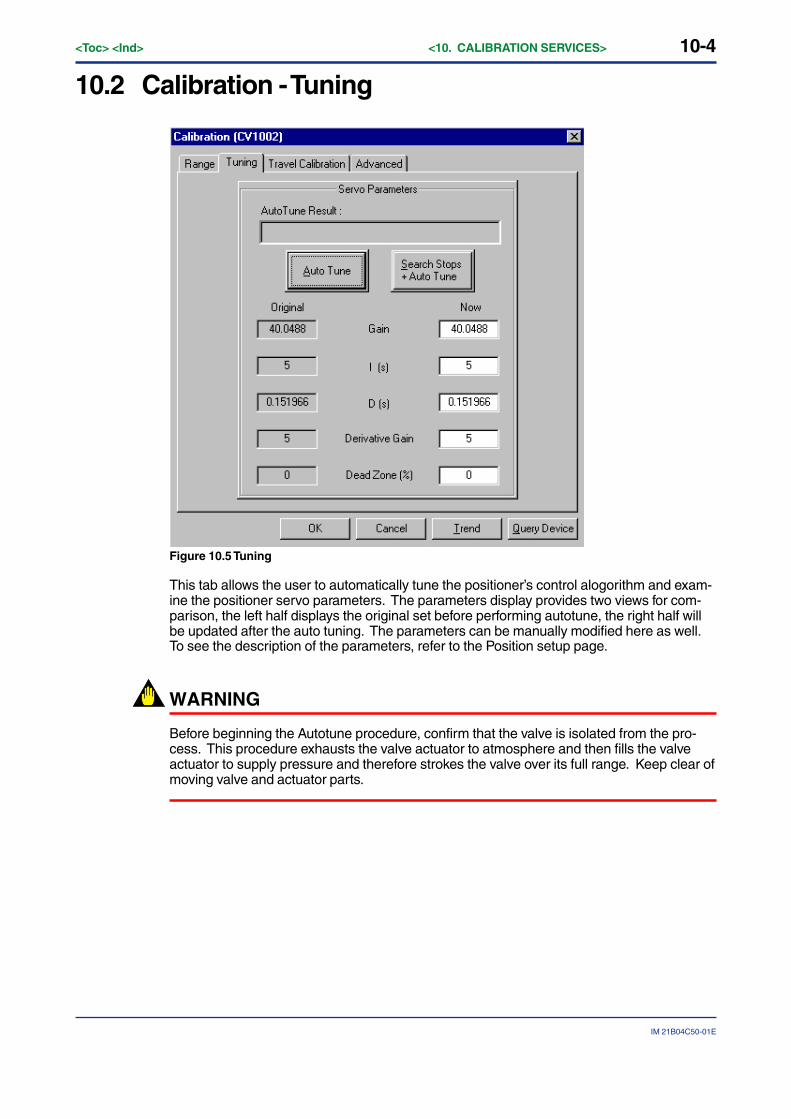
10-4<Toc> <Ind> <10. CALIBRATION SERVICES>
IM 21B04C50-01E
10.2 Calibration - Tuning
Figure 10.5 Tuning
This tab allows the user to automatically tune the positioner’s control alogorithm and exam-ine the positioner servo parameters. The parameters display provides two views for com-parison, the left half displays the original set before performing autotune, the right half willbe updated after the auto tuning. The parameters can be manually modified here as well.To see the description of the parameters, refer to the Position setup page.
WARNING
Before beginning the Autotune procedure, confirm that the valve is isolated from the pro-cess. This procedure exhausts the valve actuator to atmosphere and then fills the valveactuator to supply pressure and therefore strokes the valve over its full range. Keep clear ofmoving valve and actuator parts.

10-5
IM 21B04C50-01E
<Toc> <Ind> <10. CALIBRATION SERVICES>
10.2.1 Auto TuneClick the Auto Tune button to execute the auto tuning procedure.
After clicking Auto Tune, a dialog will appear to warn that the valve will stroke. Click yes ifthe valve is isolated from the process and if it is safe to proceed. Observe all safety precau-tions.
Figure 10.6 Autotune warning dialog
Figure 10.7 Progress Tuning
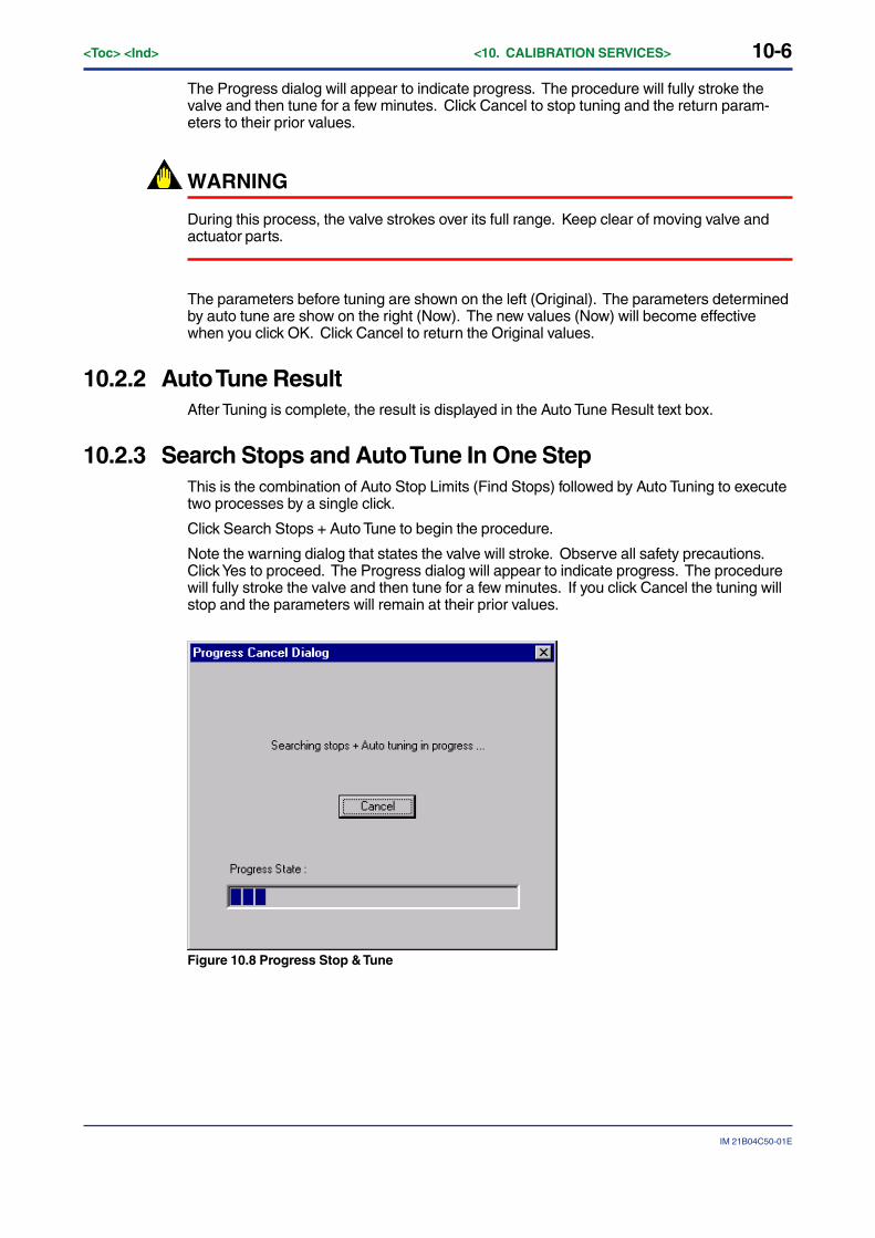
10-6<Toc> <Ind> <10. CALIBRATION SERVICES>
IM 21B04C50-01E
The Progress dialog will appear to indicate progress. The procedure will fully stroke thevalve and then tune for a few minutes. Click Cancel to stop tuning and the return param-eters to their prior values.
WARNING
During this process, the valve strokes over its full range. Keep clear of moving valve andactuator parts.
The parameters before tuning are shown on the left (Original). The parameters determinedby auto tune are show on the right (Now). The new values (Now) will become effectivewhen you click OK. Click Cancel to return the Original values.
10.2.2 Auto Tune ResultAfter Tuning is complete, the result is displayed in the Auto Tune Result text box.
10.2.3 Search Stops and Auto Tune In One StepThis is the combination of Auto Stop Limits (Find Stops) followed by Auto Tuning to executetwo processes by a single click.
Click Search Stops + Auto Tune to begin the procedure.
Note the warning dialog that states the valve will stroke. Observe all safety precautions.Click Yes to proceed. The Progress dialog will appear to indicate progress. The procedurewill fully stroke the valve and then tune for a few minutes. If you click Cancel the tuning willstop and the parameters will remain at their prior values.
Figure 10.8 Progress Stop & Tune
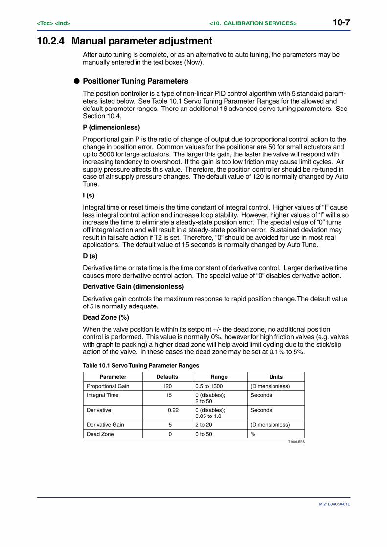
10-7
IM 21B04C50-01E
<Toc> <Ind> <10. CALIBRATION SERVICES>
10.2.4 Manual parameter adjustmentAfter auto tuning is complete, or as an alternative to auto tuning, the parameters may bemanually entered in the text boxes (Now).
● Positioner Tuning Parameters
The position controller is a type of non-linear PID control algorithm with 5 standard param-eters listed below. See Table 10.1 Servo Tuning Parameter Ranges for the allowed anddefault parameter ranges. There an additional 16 advanced servo tuning parameters. SeeSection 10.4.
P (dimensionless)
Proportional gain P is the ratio of change of output due to proportional control action to thechange in position error. Common values for the positioner are 50 for small actuators andup to 5000 for large actuators. The larger this gain, the faster the valve will respond withincreasing tendency to overshoot. If the gain is too low friction may cause limit cycles. Airsupply pressure affects this value. Therefore, the position controller should be re-tuned incase of air supply pressure changes. The default value of 120 is normally changed by AutoTune.
I (s)
Integral time or reset time is the time constant of integral control. Higher values of “I” causeless integral control action and increase loop stability. However, higher values of “I” will alsoincrease the time to eliminate a steady-state position error. The special value of “0” turnsoff integral action and will result in a steady-state position error. Sustained deviation mayresult in failsafe action if T2 is set. Therefore, “0” should be avoided for use in most realapplications. The default value of 15 seconds is normally changed by Auto Tune.
D (s)
Derivative time or rate time is the time constant of derivative control. Larger derivative timecauses more derivative control action. The special value of “0” disables derivative action.
Derivative Gain (dimensionless)
Derivative gain controls the maximum response to rapid position change. The default valueof 5 is normally adequate.
Dead Zone (%)
When the valve position is within its setpoint +/- the dead zone, no additional positioncontrol is performed. This value is normally 0%, however for high friction valves (e.g. valveswith graphite packing) a higher dead zone will help avoid limit cycling due to the stick/slipaction of the valve. In these cases the dead zone may be set at 0.1% to 5%.
Table 10.1 Servo Tuning Parameter Ranges
Parameter Defaults Range Units
Proportional Gain
Integral Time
120
15
0.5 to 1300
0 (disables);2 to 50
(Dimensionless)
Seconds
Derivative 0.22 0 (disables);0.05 to 1.0
Seconds
Derivative Gain 5 2 to 20 (Dimensionless)
Dead Zone 0 0 to 50 %T1001.EPS
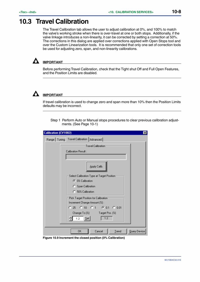
10-8<Toc> <Ind> <10. CALIBRATION SERVICES>
IM 21B04C50-01E
10.3 Travel CalibrationThe Travel Calibration tab allows the user to adjust calibration at 0%, and 100% to matchthe valve’s working stroke when there is over-travel at one or both stops. Additionally, if thevalve linkage introduces a non-linearity, it can be corrected by setting a correction at 50%.The corrections in this dialog are applied over corrections applied with Open Stops tool andover the Custom Linearization tools. It is recommended that only one set of correction toolsbe used for adjusting zero, span, and non-linearity calibrations.
IMPORTANT
Before performing Travel Calibration, check that the Tight shut Off and Full Open Features,and the Position Limits are disabled.
IMPORTANT
If travel calibration is used to change zero and span more than 10% then the Position Limitsdefaults may be incorrect.
Step 1 Perform Auto or Manual stops procedures to clear previous calibration adjust-ments. (See Page 10-1)
Figure 10.9 Increment the closed position (0% Calibration)
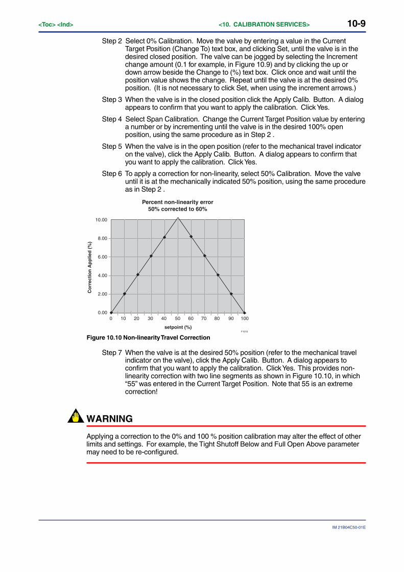
10-9
IM 21B04C50-01E
<Toc> <Ind> <10. CALIBRATION SERVICES>
Step 2 Select 0% Calibration. Move the valve by entering a value in the CurrentTarget Position (Change To) text box, and clicking Set, until the valve is in thedesired closed position. The valve can be jogged by selecting the Incrementchange amount (0.1 for example, in Figure 10.9) and by clicking the up ordown arrow beside the Change to (%) text box. Click once and wait until theposition value shows the change. Repeat until the valve is at the desired 0%position. (It is not necessary to click Set, when using the increment arrows.)
Step 3 When the valve is in the closed position click the Apply Calib. Button. A dialogappears to confirm that you want to apply the calibration. Click Yes.
Step 4 Select Span Calibration. Change the Current Target Position value by enteringa number or by incrementing until the valve is in the desired 100% openposition, using the same procedure as in Step 2 .
Step 5 When the valve is in the open position (refer to the mechanical travel indicatoron the valve), click the Apply Calib. Button. A dialog appears to confirm thatyou want to apply the calibration. Click Yes.
Step 6 To apply a correction for non-linearity, select 50% Calibration. Move the valveuntil it is at the mechanically indicated 50% position, using the same procedureas in Step 2 .
0 10 20 30 40 50 60 70 80 90 100
10.00
8.00
6.00
4.00
2.00
0.00
setpoint (%)
Co
rrec
tio
n A
pp
lied
(%
)
Percent non-linearity error50% corrected to 60%
F1010
Figure 10.10 Non-linearity Travel Correction
Step 7 When the valve is at the desired 50% position (refer to the mechanical travelindicator on the valve), click the Apply Calib. Button. A dialog appears toconfirm that you want to apply the calibration. Click Yes. This provides non-linearity correction with two line segments as shown in Figure 10.10, in which“55” was entered in the Current Target Position. Note that 55 is an extremecorrection!
WARNING
Applying a correction to the 0% and 100 % position calibration may alter the effect of otherlimits and settings. For example, the Tight Shutoff Below and Full Open Above parametermay need to be re-configured.

10-10<Toc> <Ind> <10. CALIBRATION SERVICES>
IM 21B04C50-01E
10.3.1 Calibration ResultThe result display of the travel calibration execution after Apply Calib button pressed.
10.3.2 Apply CalibStart button to execute the selected travel calibration.
10.3.3 Pick Target Position for CalibrationTo select a position for calibration, the valve needs to be moved to that position as dis-played by Current Target Position edit box (Change To). You can either type in the targetposition directly into the edit box then press Set button on the right to position the valve orclick up-down button to incrementally move the valve by the Increment Change Amountabove the edit box specified with 25, 10, 1, 0.1, or 0.01% of the total travel.
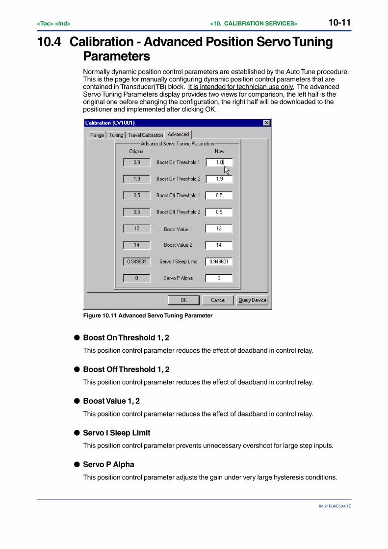
10-11
IM 21B04C50-01E
<Toc> <Ind> <10. CALIBRATION SERVICES>
10.4 Calibration - Advanced Position Servo TuningParametersNormally dynamic position control parameters are established by the Auto Tune procedure.This is the page for manually configuring dynamic position control parameters that arecontained in Transducer(TB) block. It is intended for technician use only. The advancedServo Tuning Parameters display provides two views for comparison, the left half is theoriginal one before changing the configuration, the right half will be downloaded to thepositioner and implemented after clicking OK.
Figure 10.11 Advanced Servo Tuning Parameter
● Boost On Threshold 1, 2
This position control parameter reduces the effect of deadband in control relay.
● Boost Off Threshold 1, 2
This position control parameter reduces the effect of deadband in control relay.
● Boost Value 1, 2
This position control parameter reduces the effect of deadband in control relay.
● Servo I Sleep Limit
This position control parameter prevents unnecessary overshoot for large step inputs.
● Servo P Alpha
This position control parameter adjusts the gain under very large hysteresis conditions.
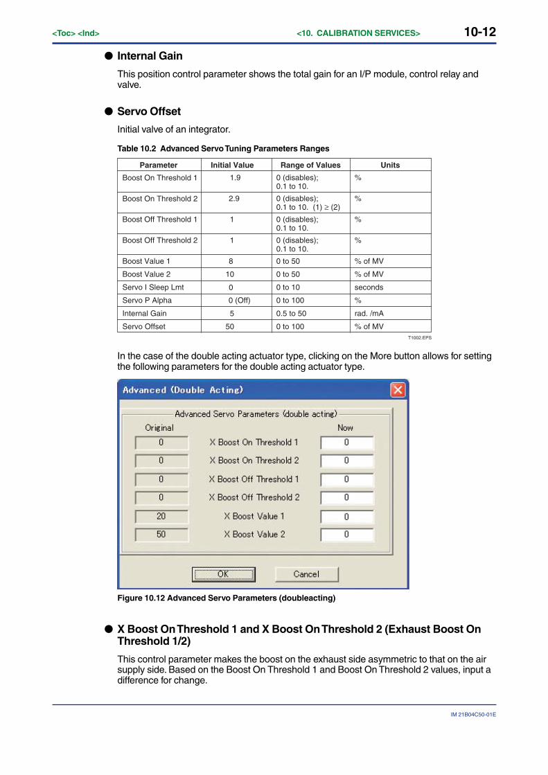
10-12<Toc> <Ind> <10. CALIBRATION SERVICES>
IM 21B04C50-01E
● Internal Gain
This position control parameter shows the total gain for an I/P module, control relay andvalve.
● Servo Offset
Initial valve of an integrator.
Table 10.2 Advanced Servo Tuning Parameters Ranges
1.9 0 (disables);0.1 to 10.
%Boost On Threshold 1
2.9 0 (disables);0.1 to 10. (1) ≥ (2)
%
Boost Off Threshold 1
Boost On Threshold 2
1 0 (disables);0.1 to 10.
%
Boost Off Threshold 2 1 0 (disables);0.1 to 10.
%
Boost Value 1 8 0 to 50 % of MV
Boost Value 2 10 0 to 50 % of MV
Servo I Sleep Lmt 0 to 10 seconds
Servo P Alpha 0 (Off)
0
0 to 100 %
Internal Gain 5 0.5 to 50 rad. /mA
Servo Offset 50 0 to 100 % of MVT1002.EPS
Parameter Initial Value Range of Values Units
In the case of the double acting actuator type, clicking on the More button allows for settingthe following parameters for the double acting actuator type.
Figure 10.12 Advanced Servo Parameters (doubleacting)
● X Boost On Threshold 1 and X Boost On Threshold 2 (Exhaust Boost OnThreshold 1/2)
This control parameter makes the boost on the exhaust side asymmetric to that on the airsupply side. Based on the Boost On Threshold 1 and Boost On Threshold 2 values, input adifference for change.
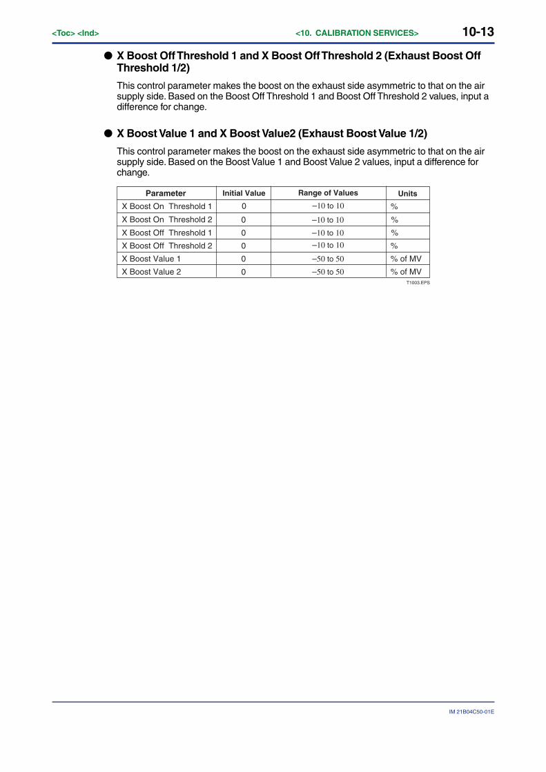
10-13
IM 21B04C50-01E
<Toc> <Ind> <10. CALIBRATION SERVICES>
● X Boost Off Threshold 1 and X Boost Off Threshold 2 (Exhaust Boost OffThreshold 1/2)
This control parameter makes the boost on the exhaust side asymmetric to that on the airsupply side. Based on the Boost Off Threshold 1 and Boost Off Threshold 2 values, input adifference for change.
● X Boost Value 1 and X Boost Value2 (Exhaust Boost Value 1/2)
This control parameter makes the boost on the exhaust side asymmetric to that on the airsupply side. Based on the Boost Value 1 and Boost Value 2 values, input a difference forchange.
0 –10 to 10 %X Boost On Threshold 1
Initial Value Range of Values UnitsParameter
X Boost On Threshold 2 0 –10 to 10 %
X Boost Off Threshold 1 0 –10 to 10 %
X Boost Off Threshold 2 0 %
X Boost Value 1 0 –50 to 50
–10 to 10
% of MV
X Boost Value 2 –50 to 50 % of MV0T1003.EPS
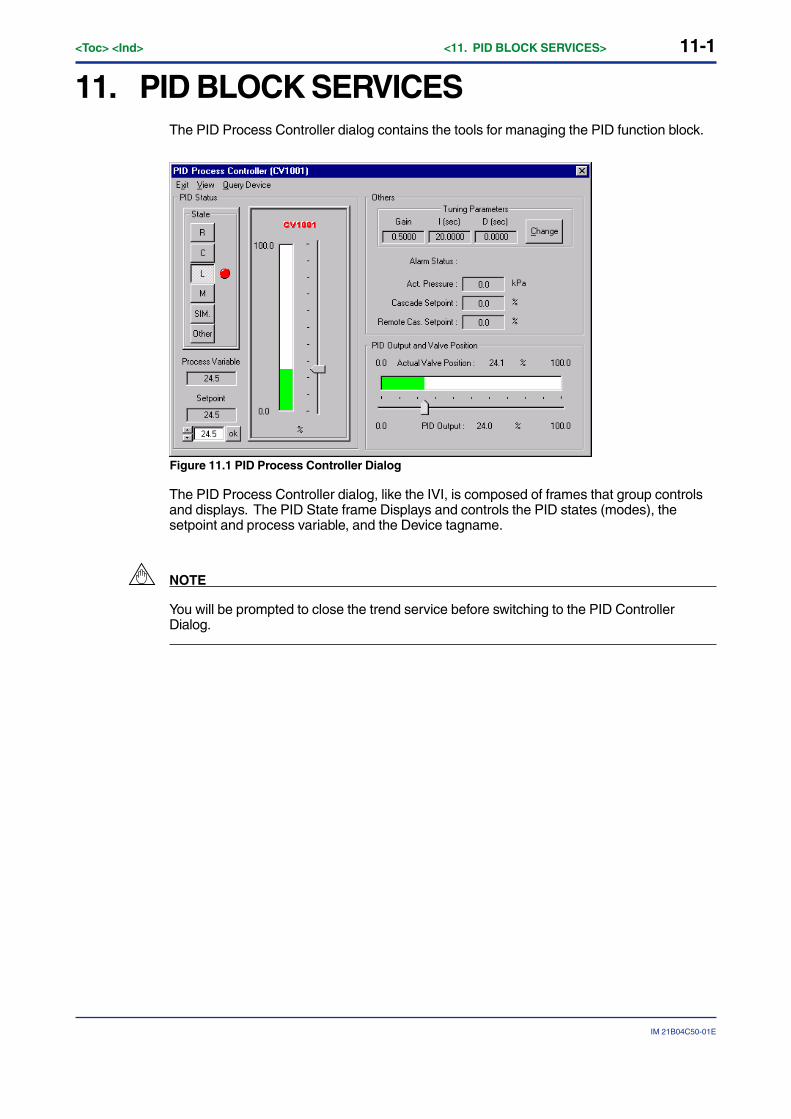
11-1
IM 21B04C50-01E
<Toc> <Ind> <11. PID BLOCK SERVICES>
11. PID BLOCK SERVICESThe PID Process Controller dialog contains the tools for managing the PID function block.
Figure 11.1 PID Process Controller Dialog
The PID Process Controller dialog, like the IVI, is composed of frames that group controlsand displays. The PID State frame Displays and controls the PID states (modes), thesetpoint and process variable, and the Device tagname.
NOTE
You will be prompted to close the trend service before switching to the PID ControllerDialog.
11-2<Toc> <Ind> <11. PID BLOCK SERVICES>
IM 21B04C50-01E
11.1 States and ModesThe permitted states of the PID block are:
• RCas selected by the R button. In this mode, the setpoint of the PID block is set by aremote application that writes to the RCAS_IN parameter regularly. This mode isallowed only if a remote application is “soft-wired” to the RCAS_IN parameter of thePID block.
• Cas selected by the C button. In this mode, the setpoint of the PID block is set by aFoundation fieldbus function block. This mode is allowed only if a Foundation fieldbusfunction block OUT is “soft-wired” to the CAS_IN parameter of the PID block, andscheduled.
• Auto selected by the L button. In this mode, the setpoint of the PID block is set by thesetpoint slider or the setpoint text box.
• Man selected by the M button. In this mode, the output of the PID is set by the outputslider or the output text box. The PID algorithm is not processed in Man.
• Simulate selected by the SIM. Button. The ValveNavi user must have the permissionlevel 8 (training level).
Note that Simulate should never be used with a device that is connected to a real process.Simulate will destroy any existing control linkages. See 11.3 before actually using thisfunction.
• Other (usually IMan or OOS) indicated by Other button. This button is an indicatoronly. It will not change the mode of the PID block.

11-3
IM 21B04C50-01E
<Toc> <Ind> <11. PID BLOCK SERVICES>
11.2 Tuning ParametersProcess tuning parameters may be adjusted from the PID Process controller dialog. ClickChange in the Tuning Parameters frame. The Proportional Gain, Integral Time andDerivative Time may be entered without changing control mode. Using the Trend service toview the effect of tuning can be performed by selecting the View>Trend menu item.
Figure 11.2 Change PID Tuning Parameters
WARNING
Changing tuning parameters to incorrect values can result in dangerous process upsets.Only trained control experts should make these changes.
● Use Trending to assist tuning
While adjusting PID process tuning parameters, it is helpful to use the trend service (SeeChapter 12) to visualize the process dynamics. After opening the trend window form thePID dialog, Click View>Trend Selection, and check the boxes for Process variable, Processsetpoint, and Target Pos.

11-4<Toc> <Ind> <11. PID BLOCK SERVICES>
IM 21B04C50-01E
11.3 Simulation FunctionThe simulation state is allowed only for the users of privelege level 8.
ValveNavi provides a special function for testing and training. The user can connect thevalve position to the input of the PID with lag of 5 seconds to allow demonstration of closedloop control.
WARNING
The simulation state must not be used if the valve is connected in a control loop or the if thevalve is controlling process flow.
The simulation state will permanently remove important control loop configurationinformation from the YVP valve positioner. The soft-wired connection between the PIDfunctions block and its input function block must be restored after simulation is used.
Reconfigure function block links after using simulate.
11.3.1 Simulation StateThis is a special state provided for training use only when the control valve is not operatinga process. In this state, the control valve position readback signal is fed back into the PIDinput with a 5 second filter time. This will form a closed loop to simulate a process loop.The PID block is in AUTO mode. (This is not the same as the Foundation fieldbusSIMULATE parameter).
To enter this state the user must be logged onto ValveNavi with permission level 8. If thereis a configured link to a process input signal (PID.IN), SIM state will permanently removethe link. For security, after using SIM state, the input signal link must be restored usingfunction block configuration tools.
To Use Simulation Function, the function block application (linkage between functionblocks) is necessary to be defined. By using Fieldbus Configureation Tool, define thelinkage between AO and PID blocks.
In PID Process Controller dialog box, clicking [SIM] button in the [Select] frame will showthe message to warn the entry to the Simulation mode. Confirm that the positioner and thevalve are isolated from the control loop and there will be no effect on the system, and thenclick Yes. The connection of the closed loop mentioned as above will be done, andSimulation mode will be started.
By changing the value of Process setpoint, you can see that the valve follows.
With using Trending function, the change in the process setpoint and the Valve targetposition /actual position can be viewed in trend graph. (See Chapter 12)
After finishing the Simulation, check and re-define the function block application again, byusing Fieldbus Configuration Tool.
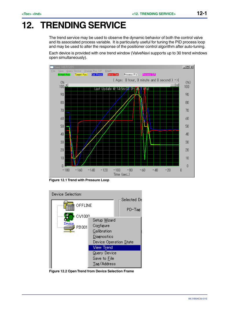
12-1
IM 21B04C50-01E
<Toc> <Ind> <12. TRENDING SERVICE>
12. TRENDING SERVICEThe trend service may be used to observe the dynamic behavior of both the control valveand its associated process variable. It is particularly useful for tuning the PID process loopand may be used to alter the response of the positioner control algorithm after auto-tuning.
Each device is provided with one trend window (ValveNavi supports up to 30 trend windowsopen simultaneously).
Figure 12.1 Trend with Pressure Loop
Figure 12.2 Open Trend from Device Selection Frame
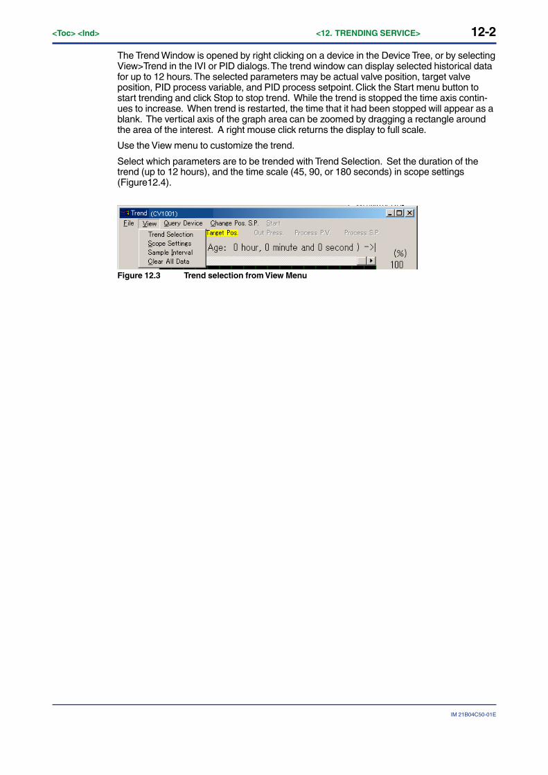
12-2<Toc> <Ind> <12. TRENDING SERVICE>
IM 21B04C50-01E
The Trend Window is opened by right clicking on a device in the Device Tree, or by selectingView>Trend in the IVI or PID dialogs. The trend window can display selected historical datafor up to 12 hours. The selected parameters may be actual valve position, target valveposition, PID process variable, and PID process setpoint. Click the Start menu button tostart trending and click Stop to stop trend. While the trend is stopped the time axis contin-ues to increase. When trend is restarted, the time that it had been stopped will appear as ablank. The vertical axis of the graph area can be zoomed by dragging a rectangle aroundthe area of the interest. A right mouse click returns the display to full scale.
Use the View menu to customize the trend.
Select which parameters are to be trended with Trend Selection. Set the duration of thetrend (up to 12 hours), and the time scale (45, 90, or 180 seconds) in scope settings(Figure12.4).
Figure 12.3 Trend selection from View Menu
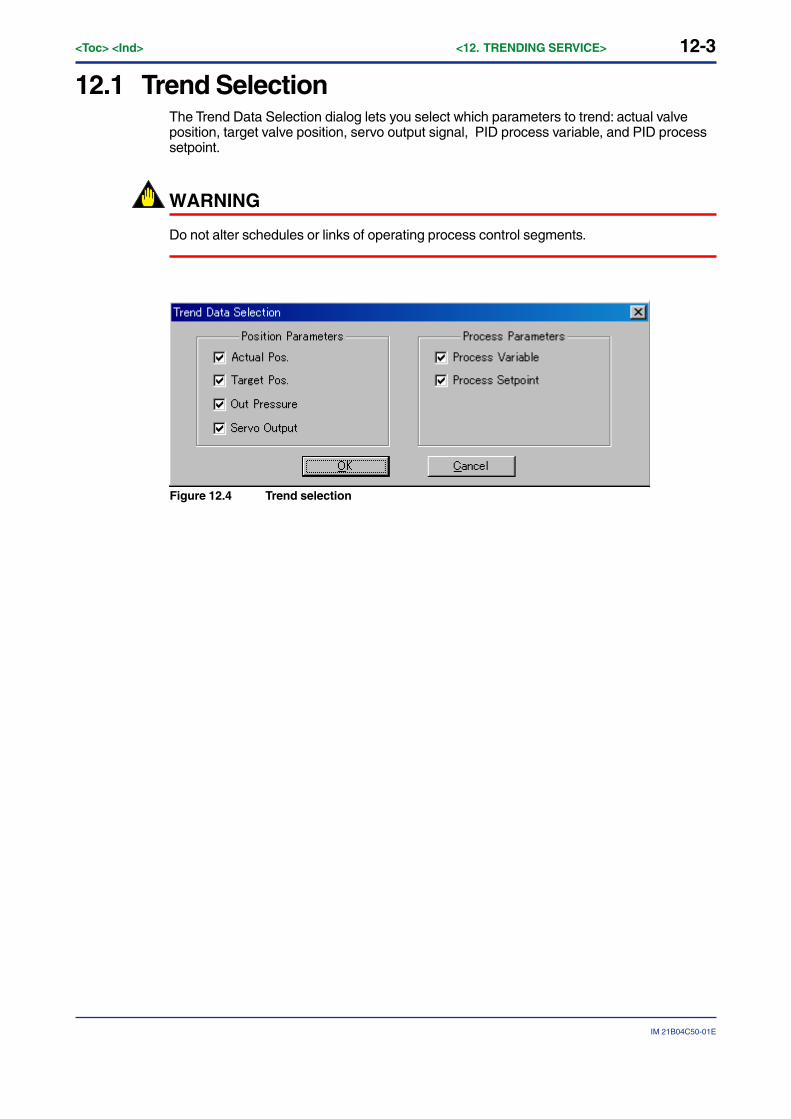
12-3
IM 21B04C50-01E
<Toc> <Ind> <12. TRENDING SERVICE>
12.1 Trend SelectionThe Trend Data Selection dialog lets you select which parameters to trend: actual valveposition, target valve position, servo output signal, PID process variable, and PID processsetpoint.
WARNING
Do not alter schedules or links of operating process control segments.
Figure 12.4 Trend selection
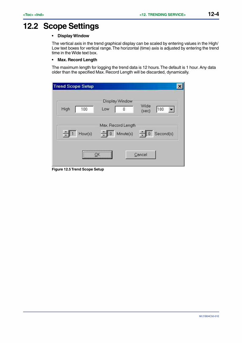
12-4<Toc> <Ind> <12. TRENDING SERVICE>
IM 21B04C50-01E
12.2 Scope Settings• Display Window
The vertical axis in the trend graphical display can be scaled by entering values in the High/Low text boxes for vertical range. The horizontal (time) axis is adjusted by entering the trendtime in the Wide text box.
• Max. Record Length
The maximum length for logging the trend data is 12 hours. The default is 1 hour. Any dataolder than the specified Max. Record Length will be discarded, dynamically.
Figure 12.5 Trend Scope Setup
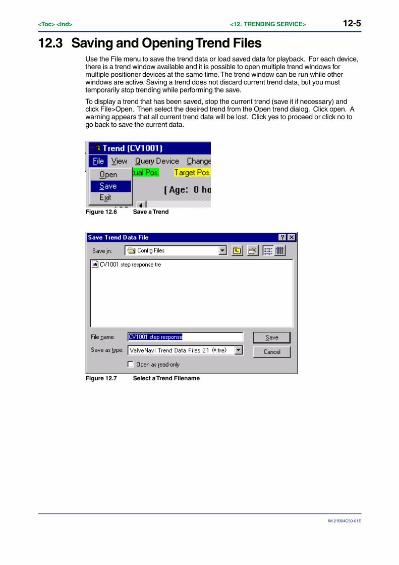
12-5
IM 21B04C50-01E
<Toc> <Ind> <12. TRENDING SERVICE>
12.3 Saving and Opening Trend FilesUse the File menu to save the trend data or load saved data for playback. For each device,there is a trend window available and it is possible to open multiple trend windows formultiple positioner devices at the same time. The trend window can be run while otherwindows are active. Saving a trend does not discard current trend data, but you musttemporarily stop trending while performing the save.
To display a trend that has been saved, stop the current trend (save it if necessary) andclick File>Open. Then select the desired trend from the Open trend dialog. Click open. Awarning appears that all current trend data will be lost. Click yes to proceed or click no togo back to save the current data.
Figure 12.6 Save a Trend
Figure 12.7 Select a Trend Filename
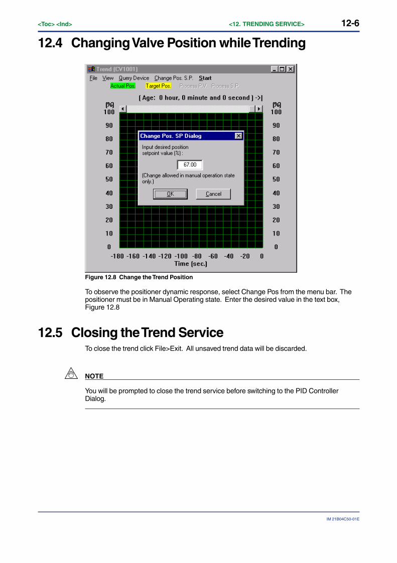
12-6<Toc> <Ind> <12. TRENDING SERVICE>
IM 21B04C50-01E
12.4 Changing Valve Position while Trending
Figure 12.8 Change the Trend Position
To observe the positioner dynamic response, select Change Pos from the menu bar. Thepositioner must be in Manual Operating state. Enter the desired value in the text box,Figure 12.8
12.5 Closing the Trend ServiceTo close the trend click File>Exit. All unsaved trend data will be discarded.
NOTE
You will be prompted to close the trend service before switching to the PID ControllerDialog.
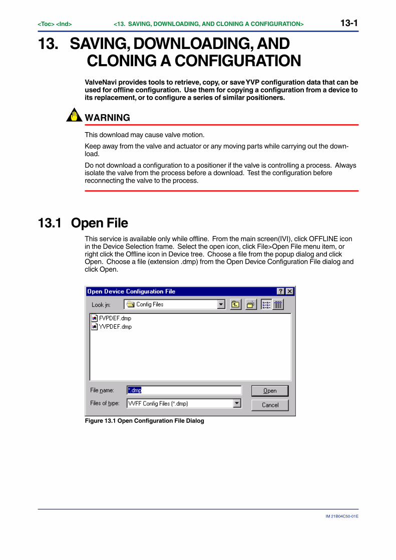
13-1
IM 21B04C50-01E
<Toc> <Ind> <13. SAVING, DOWNLOADING, AND CLONING A CONFIGURATION>
13. SAVING, DOWNLOADING, ANDCLONING A CONFIGURATIONValveNavi provides tools to retrieve, copy, or save YVP configuration data that can beused for offline configuration. Use them for copying a configuration from a device toits replacement, or to configure a series of similar positioners.
WARNING
This download may cause valve motion.
Keep away from the valve and actuator or any moving parts while carrying out the down-load.
Do not download a configuration to a positioner if the valve is controlling a process. Alwaysisolate the valve from the process before a download. Test the configuration beforereconnecting the valve to the process.
13.1 Open FileThis service is available only while offline. From the main screen(IVI), click OFFLINE iconin the Device Selection frame. Select the open icon, click File>Open File menu item, orright click the Offline icon in Device tree. Choose a file from the popup dialog and clickOpen. Choose a file (extension .dmp) from the Open Device Configuration File dialog andclick Open.
Figure 13.1 Open Configuration File Dialog
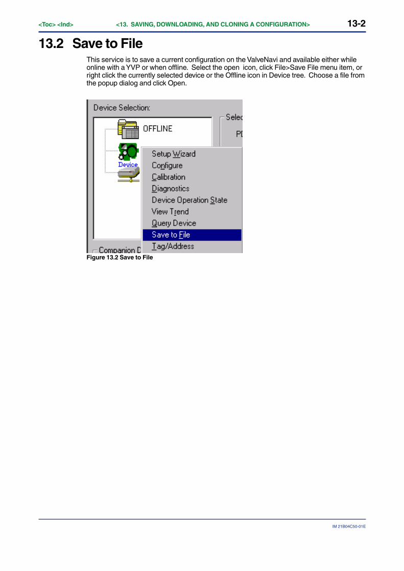
13-2<Toc> <Ind> <13. SAVING, DOWNLOADING, AND CLONING A CONFIGURATION>
IM 21B04C50-01E
13.2 Save to FileThis service is to save a current configuration on the ValveNavi and available either whileonline with a YVP or when offline. Select the open icon, click File>Save File menu item, orright click the currently selected device or the Offline icon in Device tree. Choose a file fromthe popup dialog and click Open.
Figure 13.2 Save to File
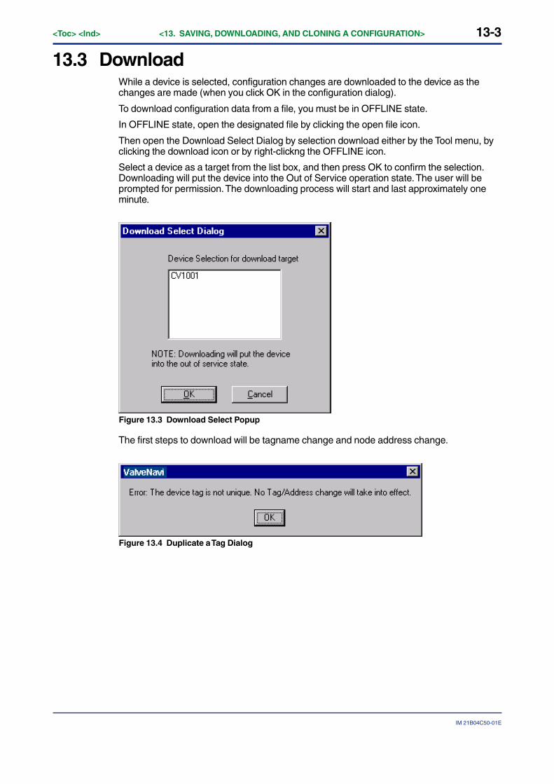
13-3
IM 21B04C50-01E
<Toc> <Ind> <13. SAVING, DOWNLOADING, AND CLONING A CONFIGURATION>
13.3 DownloadWhile a device is selected, configuration changes are downloaded to the device as thechanges are made (when you click OK in the configuration dialog).
To download configuration data from a file, you must be in OFFLINE state.
In OFFLINE state, open the designated file by clicking the open file icon.
Then open the Download Select Dialog by selection download either by the Tool menu, byclicking the download icon or by right-clickng the OFFLINE icon.
Select a device as a target from the list box, and then press OK to confirm the selection.Downloading will put the device into the Out of Service operation state. The user will beprompted for permission. The downloading process will start and last approximately oneminute.
Figure 13.3 Download Select Popup
The first steps to download will be tagname change and node address change.
Figure 13.4 Duplicate a Tag Dialog
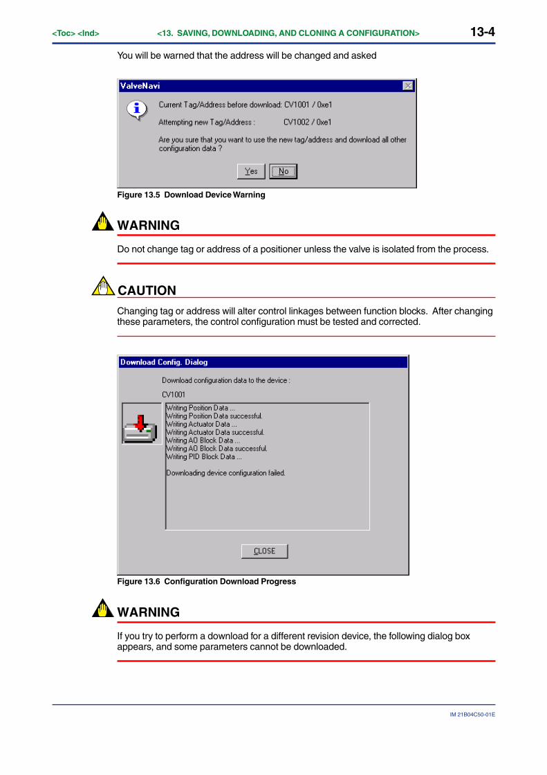
13-4<Toc> <Ind> <13. SAVING, DOWNLOADING, AND CLONING A CONFIGURATION>
IM 21B04C50-01E
You will be warned that the address will be changed and asked
Figure 13.5 Download Device Warning
WARNING
Do not change tag or address of a positioner unless the valve is isolated from the process.
CAUTION
Changing tag or address will alter control linkages between function blocks. After changingthese parameters, the control configuration must be tested and corrected.
Figure 13.6 Configuration Download Progress
WARNING
If you try to perform a download for a different revision device, the following dialog boxappears, and some parameters cannot be downloaded.

13-5
IM 21B04C50-01E
<Toc> <Ind> <13. SAVING, DOWNLOADING, AND CLONING A CONFIGURATION>
Figure 13.7 Download Warning Dialog
IMPORTANT
After the download is complete, the device must remain powered for at least 60 seconds totransfer the data to permanent memory.
13.4 Copy a Configuration to a New PositionerTo copy a configuration from a positioner to another positioner without file saving, select asource device in the device selection frame and wait until ValveNavi completes reading theconfiguration from the device. Then, select the OFFLINE icon but do not open a .dmp file.The configuration of the previously selected device remains open in ValveNavi. You maywish to disconnect the source device from the fieldbus segment to prevent accidentallyaltering its configuration. While in OFFLINE state, open Configuration Services and type inthe correct Tag and Node Address. Then, right click on Offline or use the download icon toopen the Download Selection dialog (Figure 13.3).
After configuration it is necessary to create the control function block linkages in a thirdparty fieldbus configurator.
WARNING
The download of this data will overwrite all device configuration data.
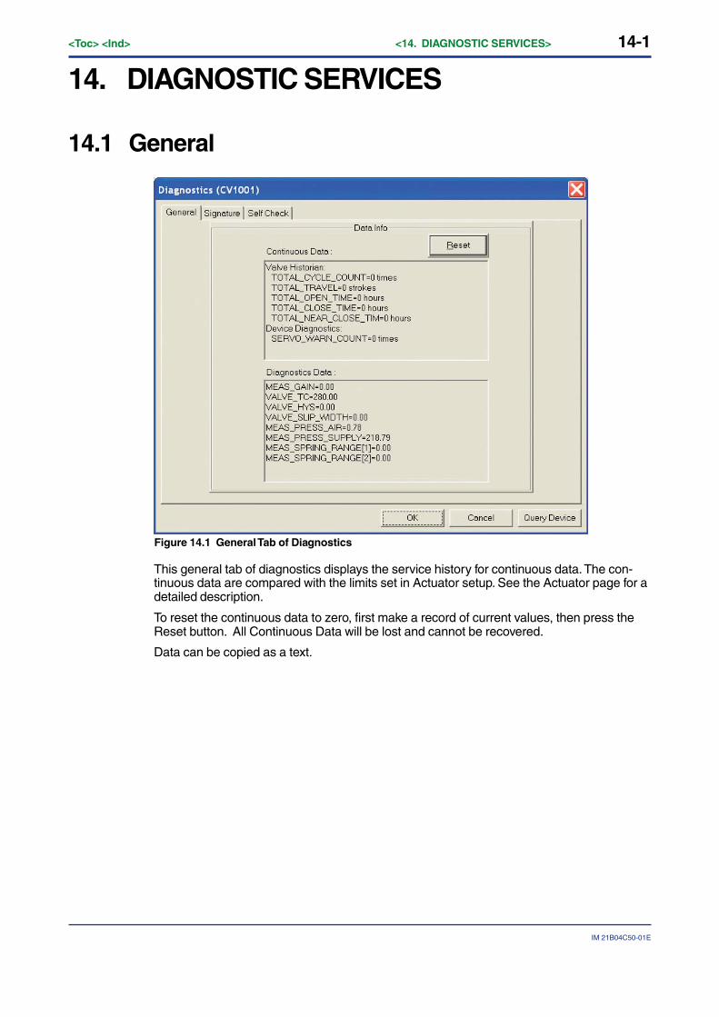
14-1
IM 21B04C50-01E
<Toc> <Ind> <14. DIAGNOSTIC SERVICES>
14. DIAGNOSTIC SERVICES
14.1 General
Figure 14.1 General Tab of Diagnostics
This general tab of diagnostics displays the service history for continuous data. The con-tinuous data are compared with the limits set in Actuator setup. See the Actuator page for adetailed description.
To reset the continuous data to zero, first make a record of current values, then press theReset button. All Continuous Data will be lost and cannot be recovered.
Data can be copied as a text.
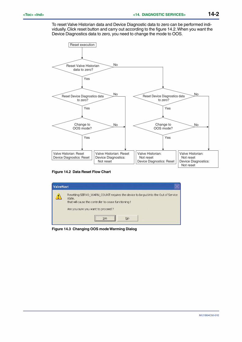
14-2<Toc> <Ind> <14. DIAGNOSTIC SERVICES>
IM 21B04C50-01E
To reset Valve Historian data and Device Diagnostic data to zero can be performed indi-vidually. Click reset button and carry out according to the figure 14.2. When you want theDevice Diagnostics data to zero, you need to change the mode to OOS.
Reset execution
Yes
No
No No
Yes
Yes
NoNo
Yes
Yes
Yes
Valve Historian: ResetDevice Diagnostics: Reset
Valve Historian: ResetDevice Diagnostics: Not reset
Valve Historian: Not resetDevice Diagnostics: Reset
Valve Historian: Not resetDevice Diagnostics: Not reset
Reset Valve Historian data to zero?
Reset Device Diagnostics data to zero?
Change to OOS mode?
Change to OOS mode?
Reset Device Diagnostics data to zero?
Figure 14.2 Data Reset Flow Chart
Figure 14.3 Changing OOS mode Warming Dialog
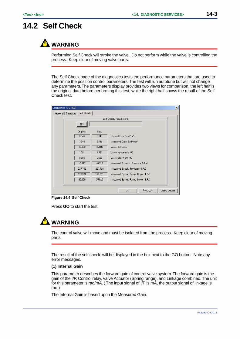
14-3
IM 21B04C50-01E
<Toc> <Ind> <14. DIAGNOSTIC SERVICES>
14.2 Self Check
WARNING
Performing Self Check will stroke the valve. Do not perform while the valve is controlling theprocess. Keep clear of moving valve parts.
The Self Check page of the diagnostics tests the performance parameters that are used todetermine the position control parameters. The test will run autotune but will not changeany parameters. The parameters display provides two views for comparison, the left half isthe original data before performing this test, while the right half shows the resulf of the SelfCheck test.
Figure 14.4 Self Check
Press GO to start the test.
WARNING
The control valve will move and must be isolated from the process. Keep clear of movingparts.
The result of the self check will be displayed in the box next to the GO button. Note anyerror messages.
(1) Internal Gain
This parameter describes the forward gain of control valve system. The forward gain is thegain of the I/P, Control relay, Valve Actuator (Spring range), and Linkage combined. The unitfor this parameter is rad/mA. ( The input signal of I/P is mA, the output signal of linkage israd.)
The Internal Gain is based upon the Measured Gain.

14-4<Toc> <Ind> <14. DIAGNOSTIC SERVICES>
IM 21B04C50-01E
(2) Measured Gain
The Measured Gain is measured by the Auto tuning function. The unit for this parameter israd/mA.
(3) Valve TC
This parameter describes the response speed of control valve system. The units for thisparameter are seconds. This parameter is measured by the Auto Tuning function. Theparameter indicates how fast the control relay can drive the air actuator.
(4) Valve Hysteresis
This parameter describes the hysteresis of the control valve. The unit for this parameter is%. This parameter is measured by the Auto Tuning function.
(5) Valve Slip Width
This parameter describes the slip width of control valve. The unit for this parameter is %.The stem of the control valve will make an abrupt movement when the pneumatic actuatorbreaks the friction of the valve packing. Slip width is the value of abrupt movement of thestem.
(6) Measured Exhaust Pressure
This parameter describes air pressure. This parameter is available only in the AP option(with pressure sensor). The units for this parameter are determined by unit index of SpringRange. The Measured Exhaust Pressure is measured by the Auto tuning function. It is thevalue of actuator pressure when the valve is at the 0% mechanical stop.
The parameter is used for diagnostics only. It is not used for tuning or control.
(7) Measured Supply Pressure
This parameter describes supply pressure. The units for this parameter are determined byunit index of Spring Range. This parameter is available only in the AP option. The MeasuredSupply Pressure is measured by the Auto tuning function. It is the value of actuator pres-sure when the valve is at the 100% mechanical stop.
The parameter is used for diagnostic only. It is not used for tuning or control.
(8) Measured Spring Range- Upper
This parameter describes upper range value of the control valve spring range. The units forthis parameter are determined by unit index of Spring Range. This parameter is availableonly in the AP option. The Measured Spring Range Upper is measured by the Auto tuningfunction.
The parameter is used for diagnostic only. It is not used for tuning or control.
(9) Measured Spring Range- Lower
This parameter is lower range value of the control valve spring range. The units for thisparameter are determined by unit index of Spring Range. This parameter is available only inthe AP option. The Measured Spring Range Lower is measured by the Auto tuning function.
This parameter is used for diagnostics only. It is not used for tuning or control.
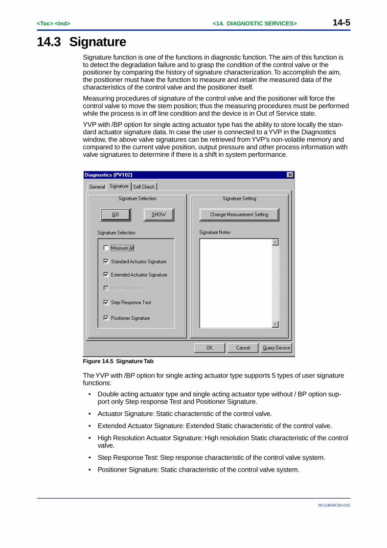
14-5
IM 21B04C50-01E
<Toc> <Ind> <14. DIAGNOSTIC SERVICES>
14.3 SignatureSignature function is one of the functions in diagnostic function. The aim of this function isto detect the degradation failure and to grasp the condition of the control valve or thepositioner by comparing the history of signature characterization. To accomplish the aim,the positioner must have the function to measure and retain the measured data of thecharacteristics of the control valve and the positioner itself.
Measuring procedures of signature of the control valve and the positioner will force thecontrol valve to move the stem position; thus the measuring procedures must be performedwhile the process is in off line condition and the device is in Out of Service state.
YVP with /BP option for single acting actuator type has the ability to store locally the stan-dard actuator signature data. In case the user is connected to a YVP in the Diagnosticswindow, the above valve signatures can be retrieved from YVP’s non-volatile memory andcompared to the current valve position, output pressure and other process information withvalve signatures to determine if there is a shift in system performance.
Figure 14.5 Signature Tab
The YVP with /BP option for single acting actuator type supports 5 types of user signaturefunctions:
• Double acting actuator type and single acting actuator type without / BP option sup-port only Step response Test and Positioner Signature.
• Actuator Signature: Static characteristic of the control valve.
• Extended Actuator Signature: Extended Static characteristic of the control valve.
• High Resolution Actuator Signature: High resolution Static characteristic of the controlvalve.
• Step Response Test: Step response characteristic of the control valve system.
• Positioner Signature: Static characteristic of the control valve system.
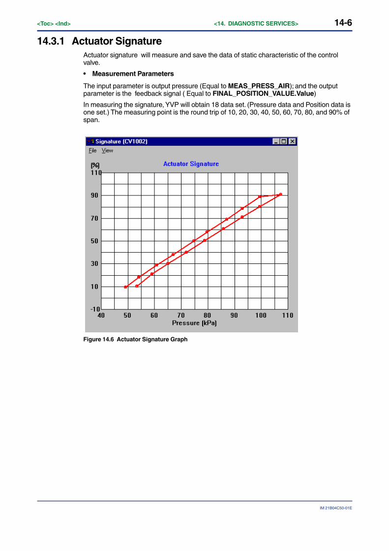
14-6<Toc> <Ind> <14. DIAGNOSTIC SERVICES>
IM 21B04C50-01E
14.3.1 Actuator SignatureActuator signature will measure and save the data of static characteristic of the controlvalve.
• Measurement Parameters
The input parameter is output pressure (Equal to MEAS_PRESS_AIR); and the outputparameter is the feedback signal ( Equal to FINAL_POSITION_VALUE.Value)
In measuring the signature, YVP will obtain 18 data set. (Pressure data and Position data isone set.) The measuring point is the round trip of 10, 20, 30, 40, 50, 60, 70, 80, and 90% ofspan.
Figure 14.6 Actuator Signature Graph
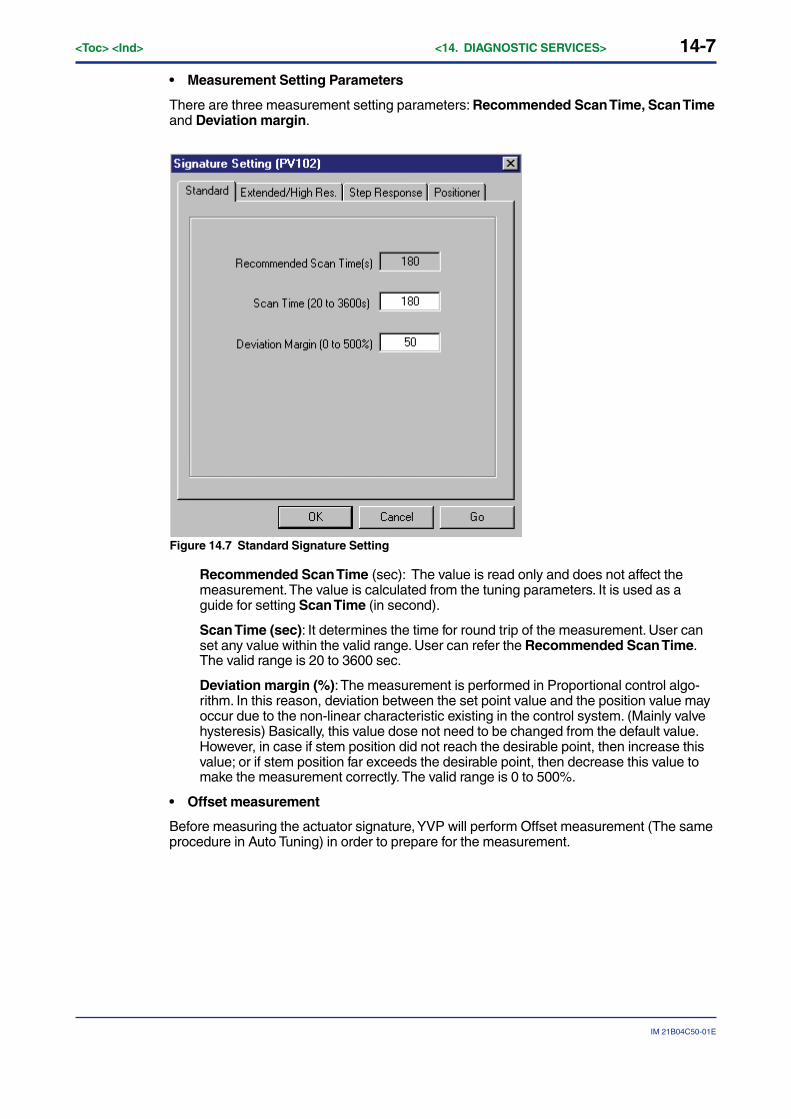
14-7
IM 21B04C50-01E
<Toc> <Ind> <14. DIAGNOSTIC SERVICES>
• Measurement Setting Parameters
There are three measurement setting parameters: Recommended Scan Time, Scan Timeand Deviation margin.
Figure 14.7 Standard Signature Setting
Recommended Scan Time (sec): The value is read only and does not affect themeasurement. The value is calculated from the tuning parameters. It is used as aguide for setting Scan Time (in second).
Scan Time (sec): It determines the time for round trip of the measurement. User canset any value within the valid range. User can refer the Recommended Scan Time.The valid range is 20 to 3600 sec.
Deviation margin (%): The measurement is performed in Proportional control algo-rithm. In this reason, deviation between the set point value and the position value mayoccur due to the non-linear characteristic existing in the control system. (Mainly valvehysteresis) Basically, this value dose not need to be changed from the default value.However, in case if stem position did not reach the desirable point, then increase thisvalue; or if stem position far exceeds the desirable point, then decrease this value tomake the measurement correctly. The valid range is 0 to 500%.
• Offset measurement
Before measuring the actuator signature, YVP will perform Offset measurement (The sameprocedure in Auto Tuning) in order to prepare for the measurement.

14-8<Toc> <Ind> <14. DIAGNOSTIC SERVICES>
IM 21B04C50-01E
• Measurement of Spring Range and Valve Friction
To view the results, click Edit on the menu bar and select the signature graph type, and thena pop-up menu will be shown. Also, you can move the cursor to the area of signature graphand make a right click for editing oreration in a pop-up menu. Select and click ResultAnalysis to see the measured spring range and valve friction. The valve friction means thehalf of valve hysteresis.
Figure 14.8 Pop-up menu for editing graph
Figure 14.9 Measurement of Spring Range and Valve Friction
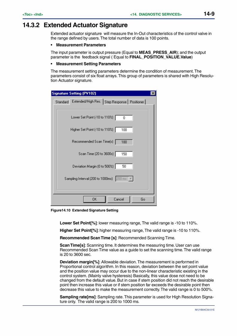
14-9
IM 21B04C50-01E
<Toc> <Ind> <14. DIAGNOSTIC SERVICES>
14.3.2 Extended Actuator SignatureExtended actuator signature will measure the In-Out characteristics of the control valve inthe range defined by users. The total number of data is 100 points.
• Measurement Parameters
The input parameter is output pressure (Equal to MEAS_PRESS_AIR); and the outputparameter is the feedback signal ( Equal to FINAL_POSITION_VALUE.Value)
• Measurement Setting Parameters
The measurement setting parameters determine the condition of measurement. Theparameters consist of six float arrays. This group of parameters is shared with High Resolu-tion Actuator signature.
Figure14.10 Extended Signature Setting
Lower Set Point[%]: lower measuring range, The valid range is -10 to 110%.
Higher Set Point[%]: higher measuring range, The valid range is -10 to 110%.
Recommended Scan Time [s]: Recommended Scanning Time.
Scan Time[s]: Scanning time. It determines the measuring time. User can useRecommended Scan Time value as a guide to set the scanning time. The valid rangeis 20 to 3600 sec.
Deviation margin[%]: Allowable deviation. The measurement is performed inProportional control algorithm. In this reason, deviation between the set point valueand the position value may occur due to the non-linear characteristic existing in thecontrol system. (Mainly valve hysteresis) Basically, this value dose not need to bechanged from the default value. But in case if stem position did not reach the desirablepoint then increase this value or if stem position far exceeds the desirable point thendecrease this value to make the measurement correctly. The valid range is 0 to 500%.
Sampling rate[ms]: Sampling rate. This parameter is used for High Resolution Signa-ture only. The valid range is 200 to 1000 ms.

14-10<Toc> <Ind> <14. DIAGNOSTIC SERVICES>
IM 21B04C50-01E
• Data to Obtain
In measuring the extended actuator signature, YVP will obtain 100 data set. (Position dataand Pressure data is one set.)
There are two data acquisition mode. Position related data acquisition and time sam-pling related data acquisition. Normally, data will be acquired according to the addressedmeasuring position point. When the valve is saturated and can not reach the measurementpoint, then data acquisition mode is switched to time sampling.
Figure14.11 Extended Signature Graph
• Offset measurement
Before measuring the extended actuator signature, YVP will perform Offset measurement(The same procedure in Auto Tuning.) in order to prepare for the measurement if selectedmeasuring mode is not Measure All.
• Measurement of Spring Range and Valve Friction
You can view the results of spring range and valve friction as in the same way at theStandard Actuator Signature.
14.3.3 High Resolution Actuator SignatureThis function is used for measuring actuator signature in high resolution. This function willmeasure the In-Out characteristic of the control valve in time sampling mode. The numberof measuring sample is dependent on the time of round-trip, and can be obtained by thefollowing Calculation: Scan Time/Sampling rate ×1000 [point].
Before measuring the signature, YVP110 will perform Offset measurement (The sameprocedure in Auto Tuning) in order to prepare for the measurement.
For details, refer to ‘14.3.2 Extended Actuator Signature’.
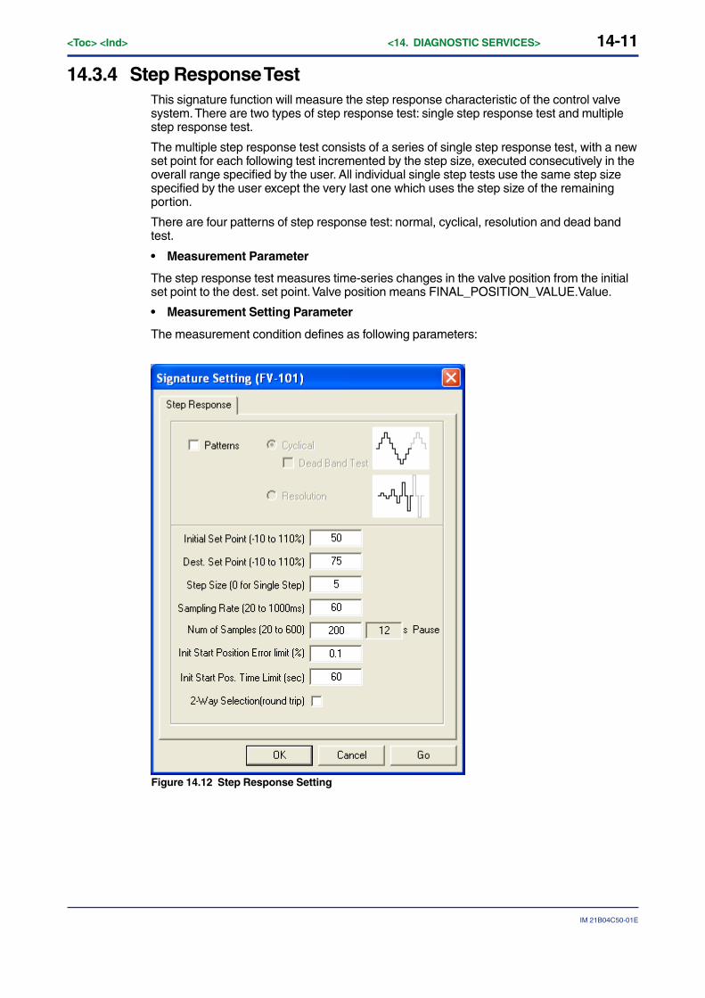
14-11
IM 21B04C50-01E
<Toc> <Ind> <14. DIAGNOSTIC SERVICES>
14.3.4 Step Response TestThis signature function will measure the step response characteristic of the control valvesystem. There are two types of step response test: single step response test and multiplestep response test.
The multiple step response test consists of a series of single step response test, with a newset point for each following test incremented by the step size, executed consecutively in theoverall range specified by the user. All individual single step tests use the same step sizespecified by the user except the very last one which uses the step size of the remainingportion.
There are four patterns of step response test: normal, cyclical, resolution and dead bandtest.
• Measurement Parameter
The step response test measures time-series changes in the valve position from the initialset point to the dest. set point. Valve position means FINAL_POSITION_VALUE.Value.
• Measurement Setting Parameter
The measurement condition defines as following parameters:
Figure 14.12 Step Response Setting

14-12<Toc> <Ind> <14. DIAGNOSTIC SERVICES>
IM 21B04C50-01E
Initial Set Point (-10 to 110%): The base position for step test from which the setpoint will change by the amount of the step size. If the step test works as cyclical,resolution and dead band test, the value fixed at 50.
Dest. Set Point (-10 to 110%): The destination position. If it is in resolution patternsstep test, the value should be over 50.
Step Size (0 for Single Step): The size of each step change. Used for multi stepresponse test only. If the step size is 0, the multi-step test becomes the single step testin the range specified by the initial set point and the dest.set point. In pattern cyclically,the step size should be the range specified by the initial set point and the dest.setpoint if the step size is 0. In pattern resolution, the step size means the first step size(in the first cycle). In pattern resolution, the default value will be 5% if the step size is 0.In dead band test, the valid range is 0.1 to 2.0%.
Sampling rate (20 to 1000ms): Sampling rate of each step. The valid range is 20 to1000ms.
Num of Samples (20 to 600): Sampling point of each step. The valid range is 20 to600.
Init Start Position Error Limit (0.1 to 3%): The maximum error allowed between theactual position (FINAL_POSITION_VALUE) and the initial set point before starting thetest. The valid range is 0.1% or more.
Init Start Position Time Limit (10 to 600sec): The maximum waiting time. If theactual position is not stabilizing within init start position error limit and within this time,step response test do not start.
2-way Selection (round trip): Selecting a round trip measurement Used for normalpattern test only. The values of the initial set point and the dest. set point determine thedirection of the valve stem movement. When the value of the initial set point is morethan that of the dest. set point, the valve steps down in one way trip, then steps up atreturn trip if 2-way selection specified.
Cycle: Number of cycles for cyclical response test.
Pause(s): Equal to Sampling rate * Number of Samples
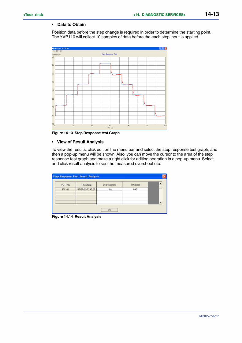
14-13
IM 21B04C50-01E
<Toc> <Ind> <14. DIAGNOSTIC SERVICES>
• Data to Obtain
Position data before the step change is required in order to determine the starting point.The YVP110 will collect 10 samples of data before the each step input is applied.
Figure 14.13 Step Response test Graph
• View of Result Analysis
To view the results, click edit on the menu bar and select the step response test graph, andthen a pop-up menu will be shown. Also, you can move the cursor to the area of the stepresponse test graph and make a right click for editing operation in a pop-up menu. Selectand click result analysis to see the measured overshoot etc.
Figure 14.14 Result Analysis
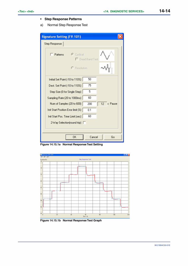
14-14<Toc> <Ind> <14. DIAGNOSTIC SERVICES>
IM 21B04C50-01E
• Step Response Patterns
a) Normal Step Response Test
Figure 14.15.1a Normal Response Test Setting
Figure 14.15.1b Normal Response Test Graph
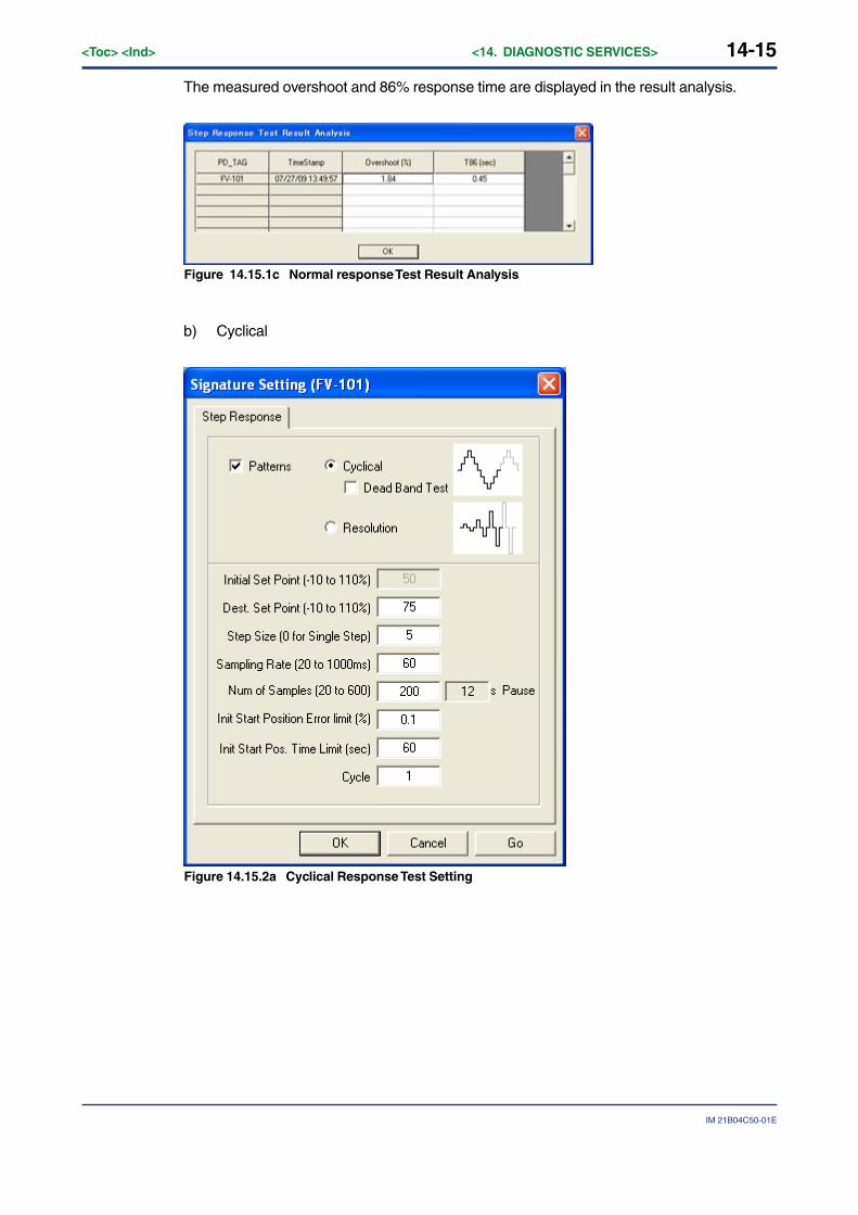
14-15
IM 21B04C50-01E
<Toc> <Ind> <14. DIAGNOSTIC SERVICES>
The measured overshoot and 86% response time are displayed in the result analysis.
Figure 14.15.1c Normal response Test Result Analysis
b) Cyclical
Figure 14.15.2a Cyclical Response Test Setting
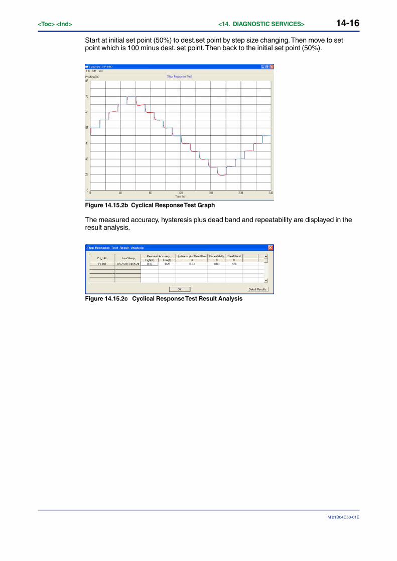
14-16<Toc> <Ind> <14. DIAGNOSTIC SERVICES>
IM 21B04C50-01E
Start at initial set point (50%) to dest.set point by step size changing. Then move to setpoint which is 100 minus dest. set point. Then back to the initial set point (50%).
Figure 14.15.2b Cyclical Response Test Graph
The measured accuracy, hysteresis plus dead band and repeatability are displayed in theresult analysis.
Figure 14.15.2c Cyclical Response Test Result Analysis

14-17
IM 21B04C50-01E
<Toc> <Ind> <14. DIAGNOSTIC SERVICES>
c) Cyclical / Dead Band Test
This test is used to determine the maximum value of marginal changes in the input levelthat does not move the control valve.
Figure14.15.3a Dead Band Test Setting
Figure 14.15.3b Dead Band Test Graph
Note: YVP110 stops integral function at the Dead Band Test. Therefore, the responding actual position has deviation from SetPoint.
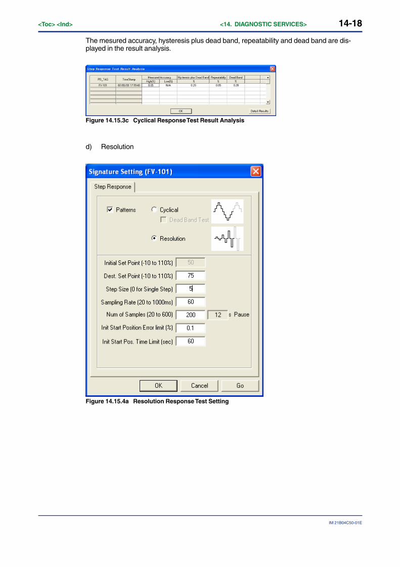
14-18<Toc> <Ind> <14. DIAGNOSTIC SERVICES>
IM 21B04C50-01E
The mesured accuracy, hysteresis plus dead band, repeatability and dead band are dis-played in the result analysis.
Figure 14.15.3c Cyclical Response Test Result Analysis
d) Resolution
Figure 14.15.4a Resolution Response Test Setting
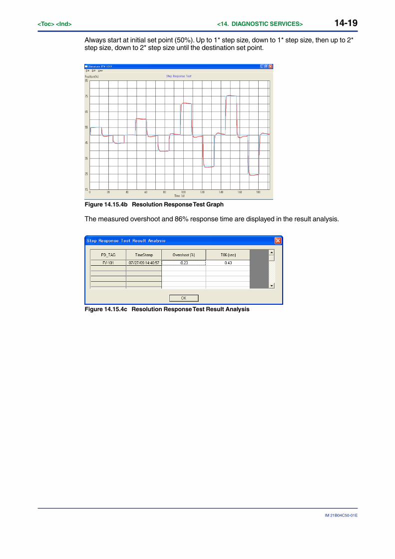
14-19
IM 21B04C50-01E
<Toc> <Ind> <14. DIAGNOSTIC SERVICES>
Always start at initial set point (50%). Up to 1* step size, down to 1* step size, then up to 2*step size, down to 2* step size until the destination set point.
Figure 14.15.4b Resolution Response Test Graph
The measured overshoot and 86% response time are displayed in the result analysis.
Figure 14.15.4c Resolution Response Test Result Analysis
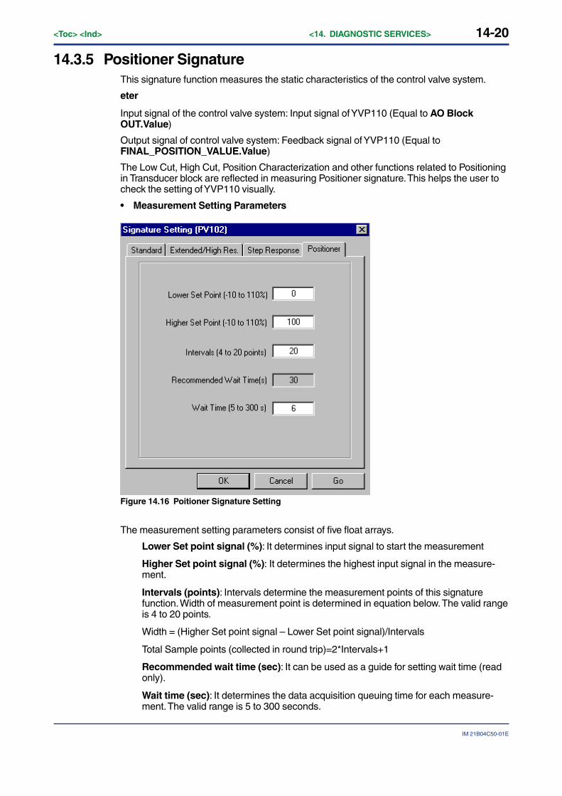
14-20<Toc> <Ind> <14. DIAGNOSTIC SERVICES>
IM 21B04C50-01E
14.3.5 Positioner SignatureThis signature function measures the static characteristics of the control valve system.
eter
Input signal of the control valve system: Input signal of YVP110 (Equal to AO BlockOUT.Value)
Output signal of control valve system: Feedback signal of YVP110 (Equal toFINAL_POSITION_VALUE.Value)
The Low Cut, High Cut, Position Characterization and other functions related to Positioningin Transducer block are reflected in measuring Positioner signature. This helps the user tocheck the setting of YVP110 visually.
• Measurement Setting Parameters
Figure 14.16 Poitioner Signature Setting
The measurement setting parameters consist of five float arrays.
Lower Set point signal (%): It determines input signal to start the measurement
Higher Set point signal (%): It determines the highest input signal in the measure-ment.
Intervals (points): Intervals determine the measurement points of this signaturefunction. Width of measurement point is determined in equation below. The valid rangeis 4 to 20 points.
Width = (Higher Set point signal – Lower Set point signal)/Intervals
Total Sample points (collected in round trip)=2*Intervals+1
Recommended wait time (sec): It can be used as a guide for setting wait time (readonly).
Wait time (sec): It determines the data acquisition queuing time for each measure-ment. The valid range is 5 to 300 seconds.
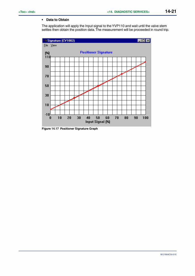
14-21
IM 21B04C50-01E
<Toc> <Ind> <14. DIAGNOSTIC SERVICES>
• Data to Obtain
The application will apply the Input signal to the YVP110 and wait until the valve stemsettles then obtain the position data. The measurement will be proceeded in round trip.
Figure 14.17 Positioner Signature Graph
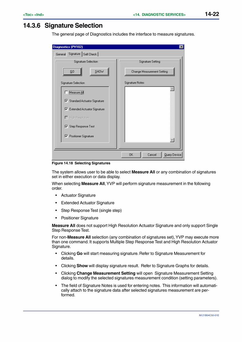
14-22<Toc> <Ind> <14. DIAGNOSTIC SERVICES>
IM 21B04C50-01E
14.3.6 Signature SelectionThe general page of Diagnostics includes the interface to measure signatures.
Figure 14.18 Selecting Signatures
The system allows user to be able to select Measure All or any combination of signaturesset in either execution or data display.
When selecting Measure All, YVP will perform signature measurement in the followingorder.
• Actuator Signature
• Extended Actuator Signature
• Step Response Test (single step)
• Positioner Signature
Measure All does not support High Resolution Actuator Signature and only support SingleStep Response Test.
For non-Measure All selection (any combination of signatures set), YVP may execute morethan one command. It supports Multiple Step Response Test and High Resolution ActuatorSignature.
• Clicking Go will start measuring signature. Refer to Signature Measurement fordetails.
• Clicking Show will display signature result. Refer to Signature Graphs for details.
• Clicking Change Measurement Setting will open Signature Measurement Settingdialog to modify the selected signatures measurement condition (setting parameters).
• The field of Signature Notes is used for entering notes. This information will automati-cally attach to the signature data after selected signatures measurement are per-formed.
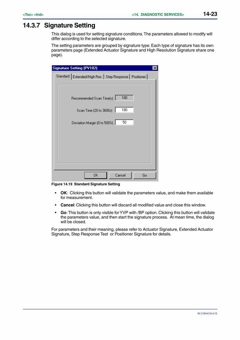
14-23
IM 21B04C50-01E
<Toc> <Ind> <14. DIAGNOSTIC SERVICES>
14.3.7 Signature SettingThis dialog is used for setting signature conditions. The parameters allowed to modify willdiffer according to the selected signature.
The setting parameters are grouped by signature type. Each type of signature has its ownparameters page (Extended Actuator Signature and High Resolution Signature share onepage).
Figure 14.19 Standard Signature Setting
• OK: Clicking this button will validate the parameters value, and make them availablefor measurement.
• Cancel: Clicking this button will discard all modified value and close this window.
• Go: This button is only visible for YVP with /BP option. Clicking this button will validatethe parameters value, and then start the signature process. At mean time, the dialogwill be closed.
For parameters and their meaning, please refer to Actuator Signature, Extended ActuatorSignature, Step Response Test or Positioner Signature for details.
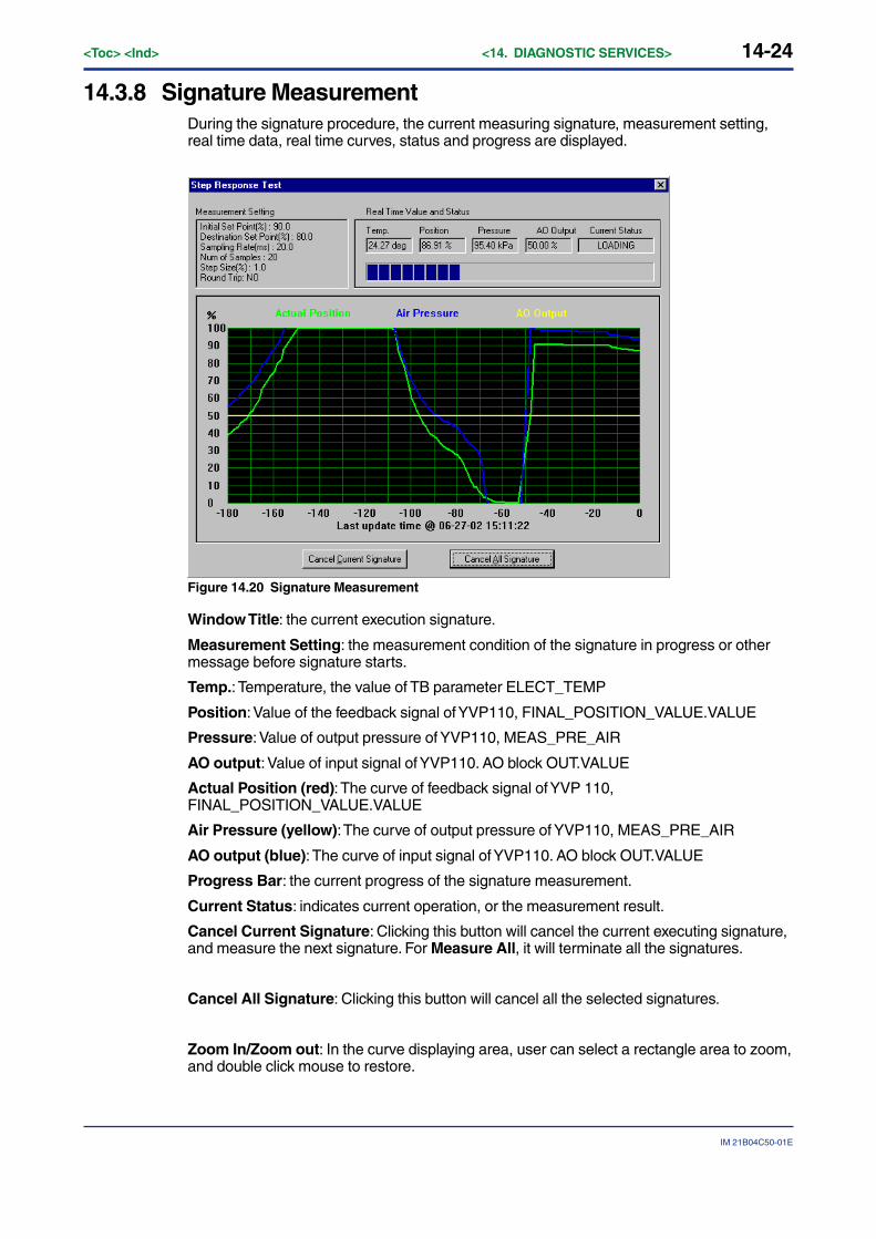
14-24<Toc> <Ind> <14. DIAGNOSTIC SERVICES>
IM 21B04C50-01E
14.3.8 Signature MeasurementDuring the signature procedure, the current measuring signature, measurement setting,real time data, real time curves, status and progress are displayed.
Figure 14.20 Signature Measurement
Window Title: the current execution signature.
Measurement Setting: the measurement condition of the signature in progress or othermessage before signature starts.
Temp.: Temperature, the value of TB parameter ELECT_TEMP
Position: Value of the feedback signal of YVP110, FINAL_POSITION_VALUE.VALUE
Pressure: Value of output pressure of YVP110, MEAS_PRE_AIR
AO output: Value of input signal of YVP110. AO block OUT.VALUE
Actual Position (red): The curve of feedback signal of YVP 110,FINAL_POSITION_VALUE.VALUE
Air Pressure (yellow): The curve of output pressure of YVP110, MEAS_PRE_AIR
AO output (blue): The curve of input signal of YVP110. AO block OUT.VALUE
Progress Bar: the current progress of the signature measurement.
Current Status: indicates current operation, or the measurement result.
Cancel Current Signature: Clicking this button will cancel the current executing signature,and measure the next signature. For Measure All, it will terminate all the signatures.
Cancel All Signature: Clicking this button will cancel all the selected signatures.
Zoom In/Zoom out: In the curve displaying area, user can select a rectangle area to zoom,and double click mouse to restore.
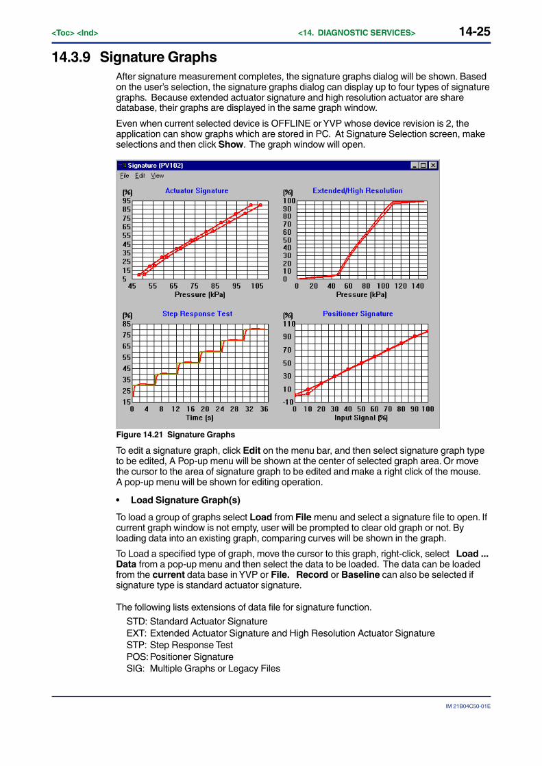
14-25
IM 21B04C50-01E
<Toc> <Ind> <14. DIAGNOSTIC SERVICES>
14.3.9 Signature GraphsAfter signature measurement completes, the signature graphs dialog will be shown. Basedon the user’s selection, the signature graphs dialog can display up to four types of signaturegraphs. Because extended actuator signature and high resolution actuator are sharedatabase, their graphs are displayed in the same graph window.
Even when current selected device is OFFLINE or YVP whose device revision is 2, theapplication can show graphs which are stored in PC. At Signature Selection screen, makeselections and then click Show. The graph window will open.
Figure 14.21 Signature Graphs
To edit a signature graph, click Edit on the menu bar, and then select signature graph typeto be edited, A Pop-up menu will be shown at the center of selected graph area. Or movethe cursor to the area of signature graph to be edited and make a right click of the mouse.A pop-up menu will be shown for editing operation.
• Load Signature Graph(s)
To load a group of graphs select Load from File menu and select a signature file to open. Ifcurrent graph window is not empty, user will be prompted to clear old graph or not. Byloading data into an existing graph, comparing curves will be shown in the graph.
To Load a specified type of graph, move the cursor to this graph, right-click, select Load ...Data from a pop-up menu and then select the data to be loaded. The data can be loadedfrom the current data base in YVP or File. Record or Baseline can also be selected ifsignature type is standard actuator signature.
The following lists extensions of data file for signature function.
STD: Standard Actuator SignatureEXT: Extended Actuator Signature and High Resolution Actuator SignatureSTP: Step Response TestPOS:Positioner SignatureSIG: Multiple Graphs or Legacy Files
14-26<Toc> <Ind> <14. DIAGNOSTIC SERVICES>
IM 21B04C50-01E
• Save Signature Graph(s)
To save a group of graphs, select Save from menu File.
To save one specified graph, move mouse cursor to that graph, right click, and select SaveGraph from Pop-up menu.
To save data of current data base in YVP to a file, select the curve from a pop-up menu,and then select Save to File. If signature type is standard actuator signature, Save toRecord or Save to Baseline can also be selected.
• Print Signature Graph(s)
To print a group of graphs, select Print All from menu File.
To print one specified graph, select Print Graph from a pop-up menu.
• Export Signature Data
Signature data can be exported to Excel or Notepad. If Excel system is not installed, datawill be exported to notepad.
To export all data in one graph window, select Export to Excel from a pop-up menu.
To export one signature measurement data in one graph window, select a curve to exportfrom a pop-up menu, then select Export to Excel.
• Hide graph/show graph
Selecting Hide this Graph from a pop-up menu or unckecking related menu item fromView menu will hide specified graph from a window. To show this graph again, checkrelated menu item from View menu.
• Show This Graph Only/Show All Selected Graphs
Selecting Show This Graph Only from a pop-up menu will enlarge the graph in full windowand hide other graphs.
Selecting Show All Selected Graphs from a pop-up menu will restore the full windowgraph to a previous size and show other selected graphs again.
• Graph Scale Setup
Double clicking X-Axis or Y-Axis area of a graph or selecting Scales Setup from a pop-upmenu will open Graph Scale Setup dialog. Refer to ‘14. 3. 10 Graph Scale Setup’ for de-tails.
• Graph Legend
Selecting Show Legend from a pop-up menu will show the legend which includes the datasource and its measurement time stamp. The legend box is movable. By Clicking one of theitems listed in the legend box will show the summary information of the measurement.
• Show Data Points
By checking/unchecking Show Data Points from a pop-up menu, graph window will showthe signature curve with/without data dots. In default mode, Actuator Signature andPositioner Signature graph show with dots, Extended Signature/High Resolution and StepResponse Test show without dots.

14-27
IM 21B04C50-01E
<Toc> <Ind> <14. DIAGNOSTIC SERVICES>
• Show Set Points
For Step Response Test only. Checking/Unchecking Show Set Points from a pop-upmenu will display or hide the set points curve in step response graph. The default modeshows set points curve.
• Grid Line
Select a grid line figure from solid, dot, and none by clicking Grid Line from a pop-up menu.
• Zoom in/Zoom out
Zoom in: In the curve area of a graph window, a selected rectangle area by mouse will bezoom in.
Zoom out: double clicking a mouse or select Zoom Out from pop-up menu will restorecurrent displaying scale setting to default.
• Signature Summary
Selecting a curve and clicking Measurement Summary from Pop-up menu will openSignature Summary, Dialog to show signature measurement information. Refer to ‘14. 3. 12Signature Summary’ for details.
• Signature Notes
Selecting a curve and clicking Signature Notes from Pop-up menu will display User’snotes. This information is editable. Refer Signature Notes for details.
• Remove Curve
Selecting a curve and clicking Remove Curve from pop-up menu will delete the curve fromthe graph.
14.3.10 Graph Scale SetupThis dialog is used for setup signature graph windows display area.
X-Axis: display range of input parameter.
Y-Axis: display range of output parameter.
Figure 14.22 Scale setting
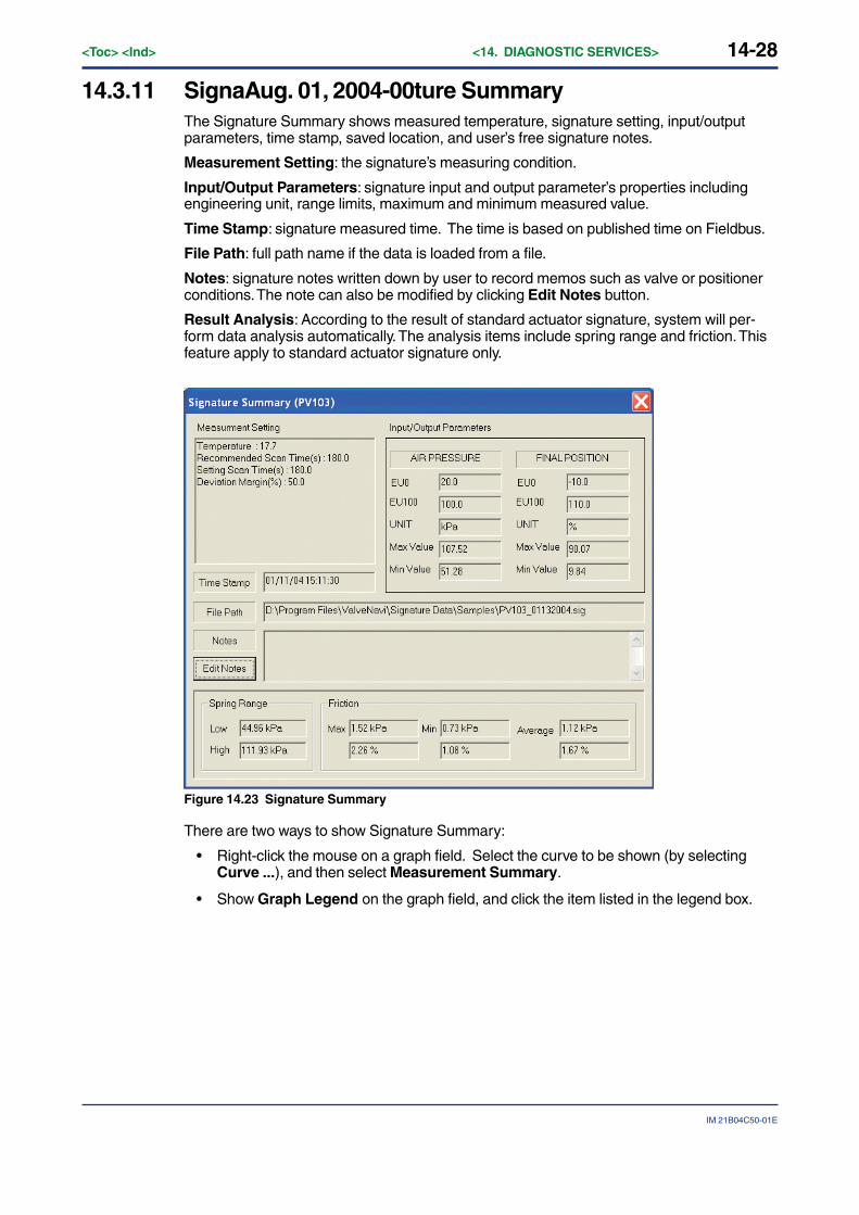
14-28<Toc> <Ind> <14. DIAGNOSTIC SERVICES>
IM 21B04C50-01E
14.3.11 SignaAug. 01, 2004-00ture SummaryThe Signature Summary shows measured temperature, signature setting, input/outputparameters, time stamp, saved location, and user’s free signature notes.
Measurement Setting: the signature’s measuring condition.
Input/Output Parameters: signature input and output parameter’s properties includingengineering unit, range limits, maximum and minimum measured value.
Time Stamp: signature measured time. The time is based on published time on Fieldbus.
File Path: full path name if the data is loaded from a file.
Notes: signature notes written down by user to record memos such as valve or positionerconditions. The note can also be modified by clicking Edit Notes button.
Result Analysis: According to the result of standard actuator signature, system will per-form data analysis automatically. The analysis items include spring range and friction. Thisfeature apply to standard actuator signature only.
Figure 14.23 Signature Summary
There are two ways to show Signature Summary:
• Right-click the mouse on a graph field. Select the curve to be shown (by selectingCurve ...), and then select Measurement Summary.
• Show Graph Legend on the graph field, and click the item listed in the legend box.
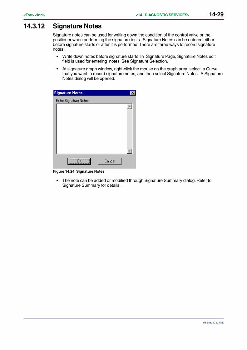
14-29
IM 21B04C50-01E
<Toc> <Ind> <14. DIAGNOSTIC SERVICES>
14.3.12 Signature NotesSignature notes can be used for writing down the condition of the control valve or thepositioner when performing the signature tests. Signature Notes can be entered eitherbefore signature starts or after it is performed. There are three ways to record signaturenotes.
• Write down notes before signature starts. In Signature Page, Signature Notes editfield is used for entering notes. See Signature Selection.
• At signature graph window, right-click the mouse on the graph area, select a Curvethat you want to record signature notes, and then select Signature Notes. A SignatureNotes dialog will be opened.
Figure 14.24 Signature Notes
• The note can be added or modified through Signature Summary dialog. Refer toSignature Summary for details.
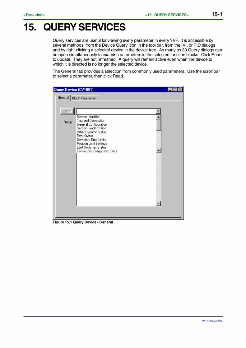
15-1
IM 21B04C50-01E
<Toc> <Ind> <15. QUERY SERVICES>
15. QUERY SERVICESQuery services are useful for viewing every parameter in every YVP. It is accessible byseveral methods: from the Device Query icon in the tool bar, from the IVI, or PID dialogsand by right-clicking a selected device in the device tree. As many as 30 Query dialogs canbe open simultaneously to examine parameters in the selected function blocks. Click Readto update. They are not refreshed. A query will remain active even when the device towhich it is directed is no longer the selected device.
The General tab provides a selection from commonly used parameters. Use the scroll barto select a parameter, then click Read.
Figure 15.1 Query Device - General
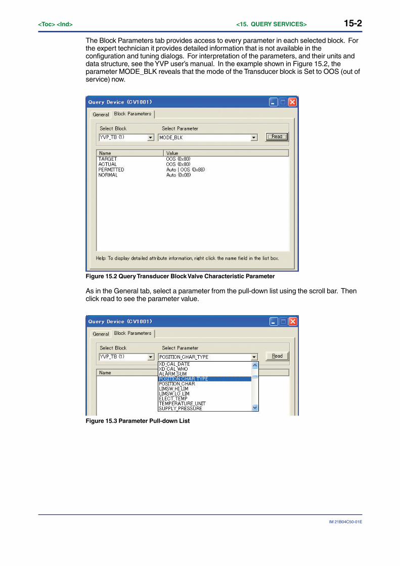
15-2<Toc> <Ind> <15. QUERY SERVICES>
IM 21B04C50-01E
The Block Parameters tab provides access to every parameter in each selected block. Forthe expert technician it provides detailed information that is not available in theconfiguration and tuning dialogs. For interpretation of the parameters, and their units anddata structure, see the YVP user’s manual. In the example shown in Figure 15.2, theparameter MODE_BLK reveals that the mode of the Transducer block is Set to OOS (out ofservice) now.
Figure 15.2 Query Transducer Block Valve Characteristic Parameter
As in the General tab, select a parameter from the pull-down list using the scroll bar. Thenclick read to see the parameter value.
Figure 15.3 Parameter Pull-down List
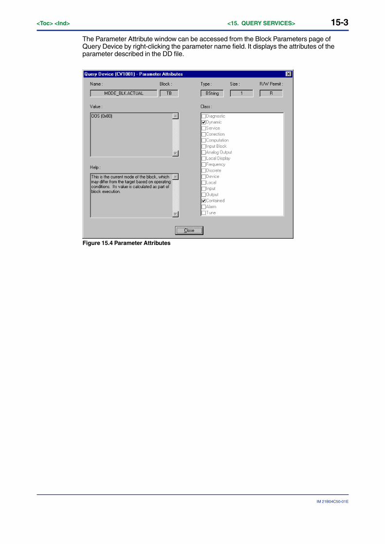
15-3
IM 21B04C50-01E
<Toc> <Ind> <15. QUERY SERVICES>
The Parameter Attribute window can be accessed from the Block Parameters page ofQuery Device by right-clicking the parameter name field. It displays the attributes of theparameter described in the DD file.
Figure 15.4 Parameter Attributes

16-1
IM 21B04C50-01E
<Toc> <Ind> <16. REPORTING SERVICES>
16. REPORTING SERVICES
16.1 Configuration ReportThis program provides a Configuration Report feature that captures a snapshot of allconfiguration data currently contained in and related to the selected device. The data areorganized into groups that are consistent with the format of the configuration user interface.The report can be either HTML format or TEXT format. The HTML-based is browserindependent. It is best viewed with the latest browser versions. Access the Generate Reportmenu item from the file menu. Then a HTML or TEXT format choice is needed.
Figure 16.1 Report Format Selection
If you select HTML format, the default browser will open the YVP configuration report as aWeb Page similar to that shown in Figure 16.2. The appearance will differ slightly betweenInternet Explorer to Netscape Navigator.
Figure 16.2 Configuration Report in Browser (IE5.0)
To save the report into a file, select File Save on the browser menu bar. To print a hard copyof the report, select File Print from the browser menu bar. Or use the browser’s print andsave toolbar icons.

16-2<Toc> <Ind> <16. REPORTING SERVICES>
IM 21B04C50-01E
● Use Report Generation to View Saved Configuration Files Services
Figure 16.2 Save Configuration Web Page Dialog
Configurations that are saved for downloading (.dmp files) to devices may be viewed withthe Report Generator in Offline State. Right click Offline and then click Open. Select theconfiguration file that has the desired data. When the Offline device loads the data, thenclick Generate Report to view and to print the data with your Web browser.
16.2 Communication Error Log
Figure 16.3 Communication Error Dialog
Occasionally, Foundation fieldbus will report communication errors. For example, if there isa loose or intermittent connection between the fieldbus segment the NI-FBUS cardinterface then communication errors may occur. ValveNavi pops up a warning dialog. Thefirst error requires acknowledgement (click OK to close) and following errors are recordedin the communication errors text box shown in Figure 16.3. The error log can be saved to atext file using the following steps.
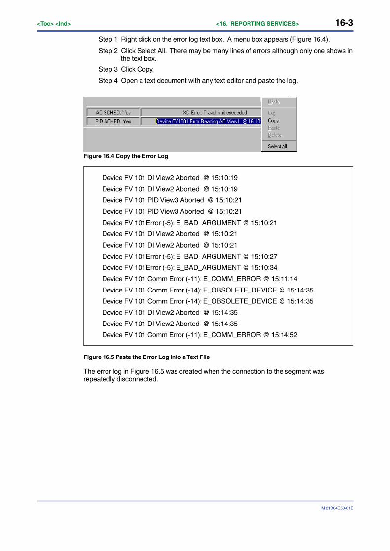
16-3
IM 21B04C50-01E
<Toc> <Ind> <16. REPORTING SERVICES>
Step 1 Right click on the error log text box. A menu box appears (Figure 16.4).
Step 2 Click Select All. There may be many lines of errors although only one shows inthe text box.
Step 3 Click Copy.
Step 4 Open a text document with any text editor and paste the log.
Figure 16.4 Copy the Error Log
Device FV 101 DI View2 Aborted @ 15:10:19
Device FV 101 DI View2 Aborted @ 15:10:19
Device FV 101 PID View3 Aborted @ 15:10:21
Device FV 101 PID View3 Aborted @ 15:10:21
Device FV 101Error (-5): E_BAD_ARGUMENT @ 15:10:21
Device FV 101 DI View2 Aborted @ 15:10:21
Device FV 101 DI View2 Aborted @ 15:10:21
Device FV 101Error (-5): E_BAD_ARGUMENT @ 15:10:27
Device FV 101Error (-5): E_BAD_ARGUMENT @ 15:10:34
Device FV 101 Comm Error (-11): E_COMM_ERROR @ 15:11:14
Device FV 101 Comm Error (-14): E_OBSOLETE_DEVICE @ 15:14:35
Device FV 101 Comm Error (-14): E_OBSOLETE_DEVICE @ 15:14:35
Device FV 101 DI View2 Aborted @ 15:14:35
Device FV 101 DI View2 Aborted @ 15:14:35
Device FV 101 Comm Error (-11): E_COMM_ERROR @ 15:14:52
Figure 16.5 Paste the Error Log into a Text File
The error log in Figure 16.5 was created when the connection to the segment wasrepeatedly disconnected.
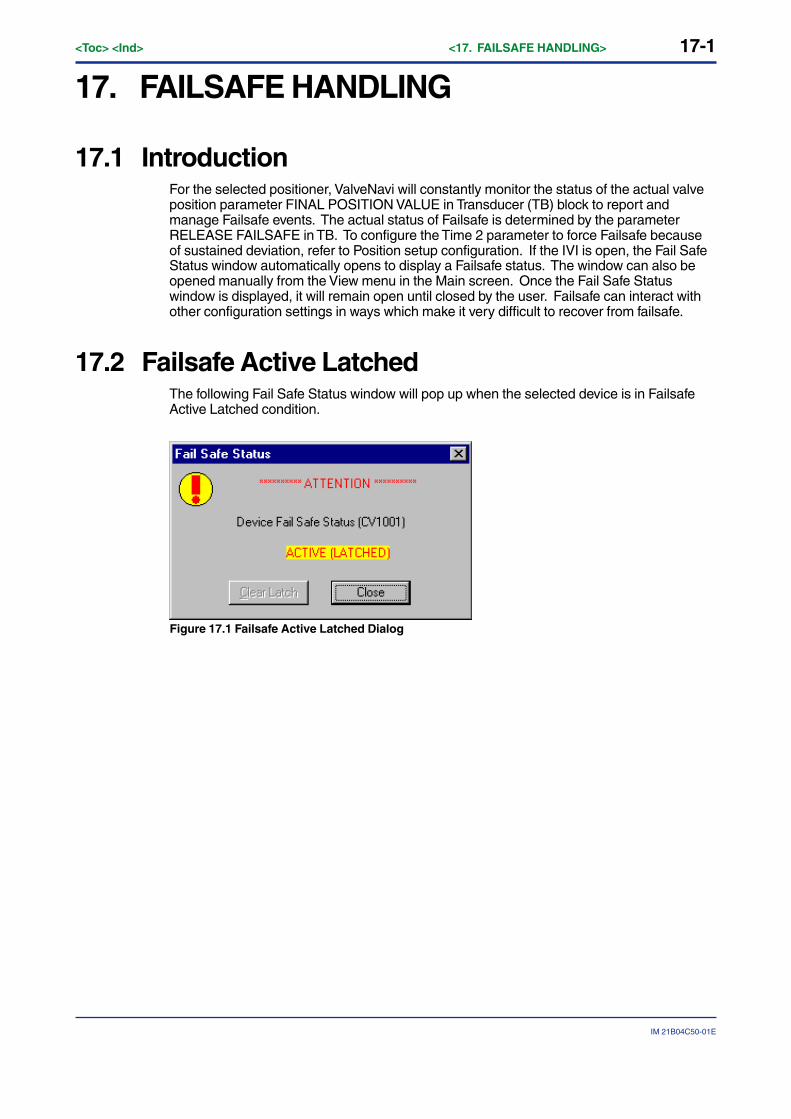
17-1
IM 21B04C50-01E
<Toc> <Ind> <17. FAILSAFE HANDLING>
17. FAILSAFE HANDLING
17.1 IntroductionFor the selected positioner, ValveNavi will constantly monitor the status of the actual valveposition parameter FINAL POSITION VALUE in Transducer (TB) block to report andmanage Failsafe events. The actual status of Failsafe is determined by the parameterRELEASE FAILSAFE in TB. To configure the Time 2 parameter to force Failsafe becauseof sustained deviation, refer to Position setup configuration. If the IVI is open, the Fail SafeStatus window automatically opens to display a Failsafe status. The window can also beopened manually from the View menu in the Main screen. Once the Fail Safe Statuswindow is displayed, it will remain open until closed by the user. Failsafe can interact withother configuration settings in ways which make it very difficult to recover from failsafe.
17.2 Failsafe Active LatchedThe following Fail Safe Status window will pop up when the selected device is in FailsafeActive Latched condition.
Figure 17.1 Failsafe Active Latched Dialog
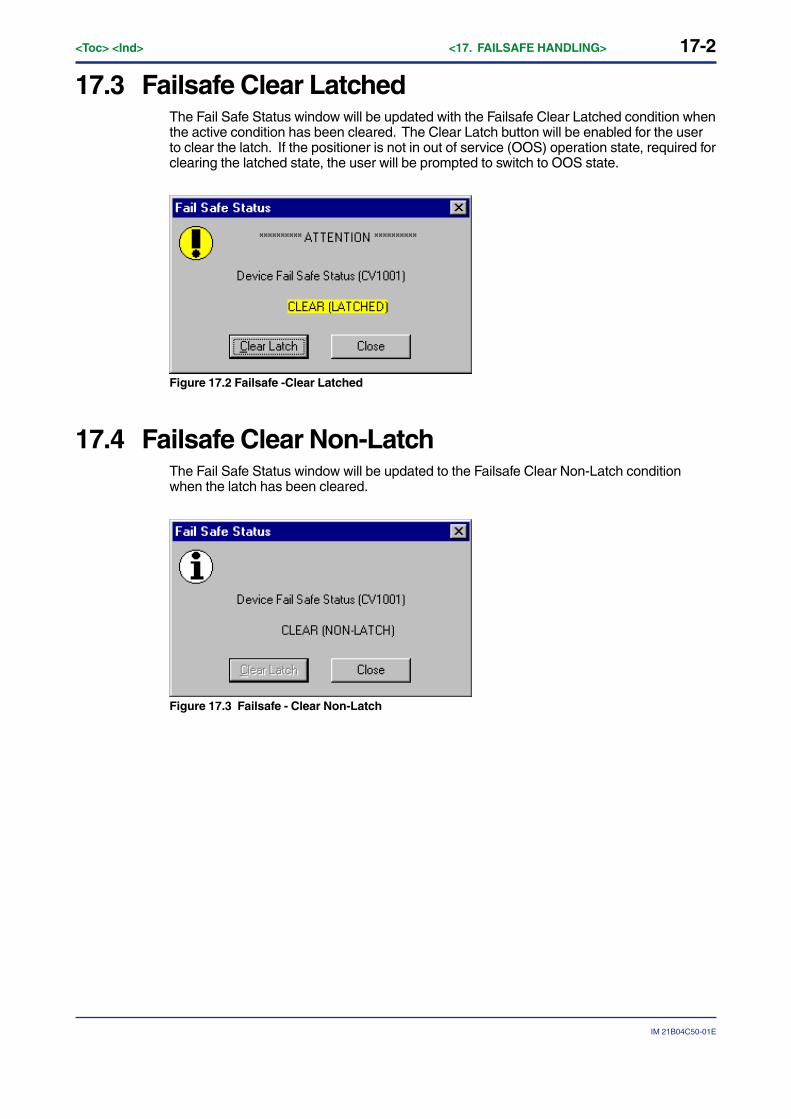
17-2<Toc> <Ind> <17. FAILSAFE HANDLING>
IM 21B04C50-01E
17.3 Failsafe Clear LatchedThe Fail Safe Status window will be updated with the Failsafe Clear Latched condition whenthe active condition has been cleared. The Clear Latch button will be enabled for the userto clear the latch. If the positioner is not in out of service (OOS) operation state, required forclearing the latched state, the user will be prompted to switch to OOS state.
Figure 17.2 Failsafe -Clear Latched
17.4 Failsafe Clear Non-LatchThe Fail Safe Status window will be updated to the Failsafe Clear Non-Latch conditionwhen the latch has been cleared.
Figure 17.3 Failsafe - Clear Non-Latch
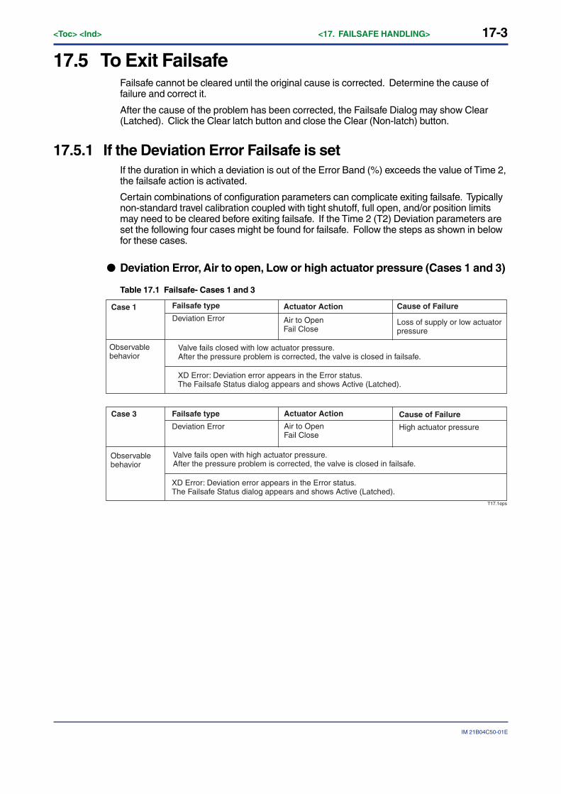
17-3
IM 21B04C50-01E
<Toc> <Ind> <17. FAILSAFE HANDLING>
17.5 To Exit FailsafeFailsafe cannot be cleared until the original cause is corrected. Determine the cause offailure and correct it.
After the cause of the problem has been corrected, the Failsafe Dialog may show Clear(Latched). Click the Clear latch button and close the Clear (Non-latch) button.
17.5.1 If the Deviation Error Failsafe is setIf the duration in which a deviation is out of the Error Band (%) exceeds the value of Time 2,the failsafe action is activated.
Certain combinations of configuration parameters can complicate exiting failsafe. Typicallynon-standard travel calibration coupled with tight shutoff, full open, and/or position limitsmay need to be cleared before exiting failsafe. If the Time 2 (T2) Deviation parameters areset the following four cases might be found for failsafe. Follow the steps as shown in belowfor these cases.
● Deviation Error, Air to open, Low or high actuator pressure (Cases 1 and 3)
Table 17.1 Failsafe- Cases 1 and 3
T17.1eps
XD Error: Deviation error appears in the Error status. The Failsafe Status dialog appears and shows Active (Latched).
Case 1
Case 3
Valve fails closed with low actuator pressure. After the pressure problem is corrected, the valve is closed in failsafe.
XD Error: Deviation error appears in the Error status. The Failsafe Status dialog appears and shows Active (Latched).
Failsafe type
Deviation Error
Actuator Action
Air to Open Fail Close
Cause of Failure
High actuator pressure
Valve fails open with high actuator pressure. After the pressure problem is corrected, the valve is closed in failsafe.
Failsafe type
Deviation Error
Actuator Action
Air to Open Fail Close
Cause of Failure
Loss of supply or low actuator pressure
Observable behavior
Observable behavior
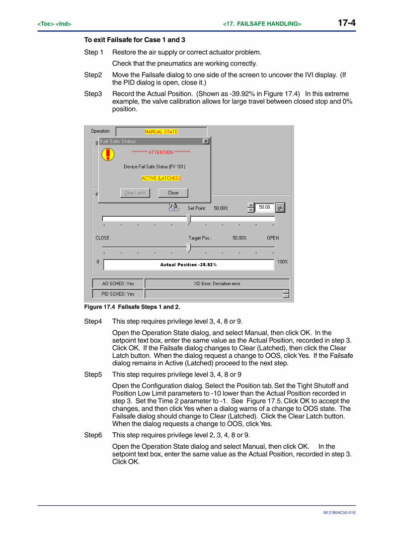
17-4<Toc> <Ind> <17. FAILSAFE HANDLING>
IM 21B04C50-01E
To exit Failsafe for Case 1 and 3
Step 1 Restore the air supply or correct actuator problem.
Check that the pneumatics are working correctly.
Step2 Move the Failsafe dialog to one side of the screen to uncover the IVI display. (Ifthe PID dialog is open, close it.)
Step3 Record the Actual Position. (Shown as -39.92% in Figure 17.4) In this extremeexample, the valve calibration allows for large travel between closed stop and 0%position.
Figure 17.4 Failsafe Steps 1 and 2.
Step4 This step requires privilege level 3, 4, 8 or 9.
Open the Operation State dialog, and select Manual, then click OK. In thesetpoint text box, enter the same value as the Actual Position, recorded in step 3.Click OK. If the Failsafe dialog changes to Clear (Latched), then click the ClearLatch button. When the dialog request a change to OOS, click Yes. If the Failsafedialog remains in Active (Latched) proceed to the next step.
Step5 This step requires privilege level 3, 4, 8 or 9
Open the Configuration dialog. Select the Position tab. Set the Tight Shutoff andPosition Low Limit parameters to -10 lower than the Actual Position recorded instep 3. Set the Time 2 parameter to -1. See Figure 17.5. Click OK to accept thechanges, and then click Yes when a dialog warns of a change to OOS state. TheFailsafe dialog should change to Clear (Latched). Click the Clear Latch button.When the dialog requests a change to OOS, click Yes.
Step6 This step requires privilege level 2, 3, 4, 8 or 9.
Open the Operation State dialog and select Manual, then click OK. In thesetpoint text box, enter the same value as the Actual Position, recorded in step 3.Click OK.
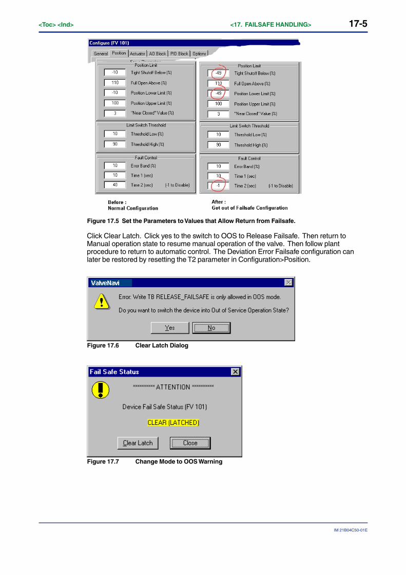
17-5
IM 21B04C50-01E
<Toc> <Ind> <17. FAILSAFE HANDLING>
Figure 17.5 Set the Parameters to Values that Allow Return from Failsafe.
Click Clear Latch. Click yes to the switch to OOS to Release Failsafe. Then return toManual operation state to resume manual operation of the valve. Then follow plantprocedure to return to automatic control. The Deviation Error Failsafe configuration canlater be restored by resetting the T2 parameter in Configuration>Position.
Figure 17.6 Clear Latch Dialog
Figure 17.7 Change Mode to OOS Warning
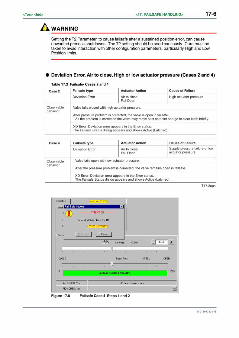
17-6<Toc> <Ind> <17. FAILSAFE HANDLING>
IM 21B04C50-01E
WARNING
Setting the T2 Parameter, to cause failsafe after a sustained position error, can causeunwanted process shutdowns. The T2 setting should be used cautiously. Care must betaken to avoid interaction with other configuration parameters, particularly High and LowPosition limits.
● Deviation Error, Air to close, High or low actuator pressure (Cases 2 and 4)
Table 17.2 Failsafe- Cases 2 and 4
T17.2eps
Case 2
Case 4
Valve fails closed with high actuator pressure.
After pressure problem is corrected, the valve is open in failsafe.- As the problem is corrected the valve may move past setpoint and go to clear latch briefly.
XD Error: Deviation error appears in the Error status. The Failsafe Status dialog appears and shows Active (Latched).
Failsafe type
Deviation Error
Actuator Action
Air to closeFail Open
Cause of Failure
Valve fails open with low actuator pressure.
After the pressure problem is corrected, the valve remains open in failsafe.
XD Error: Deviation error appears in the Error status. The Failsafe Status dialog appears and shows Active (Latched).
Failsafe type
Deviation Error
Actuator Action
Air to closeFail Open
Cause of Failure
High actuator pressure
Observable behavior
Supply pressure failure or low actuator pressure
Observable behavior
Figure 17.8 Failsafe Case 4 Steps 1 and 2
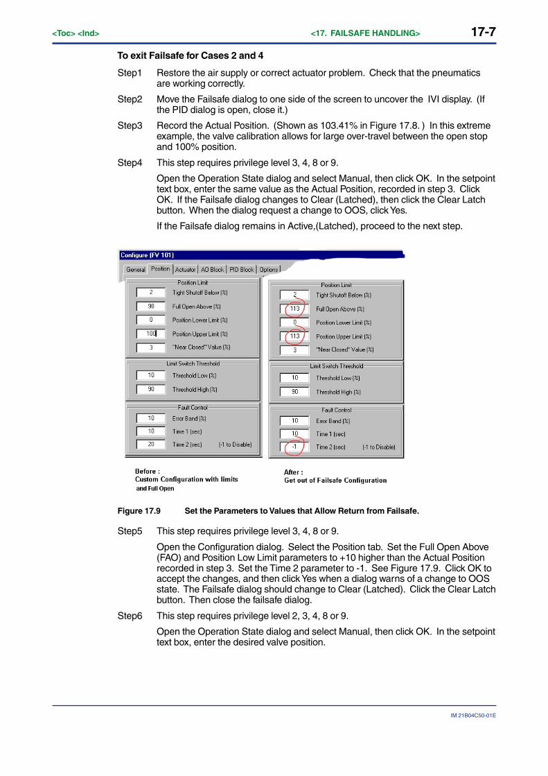
17-7
IM 21B04C50-01E
<Toc> <Ind> <17. FAILSAFE HANDLING>
To exit Failsafe for Cases 2 and 4
Step1 Restore the air supply or correct actuator problem. Check that the pneumaticsare working correctly.
Step2 Move the Failsafe dialog to one side of the screen to uncover the IVI display. (Ifthe PID dialog is open, close it.)
Step3 Record the Actual Position. (Shown as 103.41% in Figure 17.8. ) In this extremeexample, the valve calibration allows for large over-travel between the open stopand 100% position.
Step4 This step requires privilege level 3, 4, 8 or 9.
Open the Operation State dialog and select Manual, then click OK. In the setpointtext box, enter the same value as the Actual Position, recorded in step 3. ClickOK. If the Failsafe dialog changes to Clear (Latched), then click the Clear Latchbutton. When the dialog request a change to OOS, click Yes.
If the Failsafe dialog remains in Active,(Latched), proceed to the next step.
Figure 17.9 Set the Parameters to Values that Allow Return from Failsafe.
Step5 This step requires privilege level 3, 4, 8 or 9.
Open the Configuration dialog. Select the Position tab. Set the Full Open Above(FAO) and Position Low Limit parameters to +10 higher than the Actual Positionrecorded in step 3. Set the Time 2 parameter to -1. See Figure 17.9. Click OK toaccept the changes, and then click Yes when a dialog warns of a change to OOSstate. The Failsafe dialog should change to Clear (Latched). Click the Clear Latchbutton. Then close the failsafe dialog.
Step6 This step requires privilege level 2, 3, 4, 8 or 9.
Open the Operation State dialog and select Manual, then click OK. In the setpointtext box, enter the desired valve position.
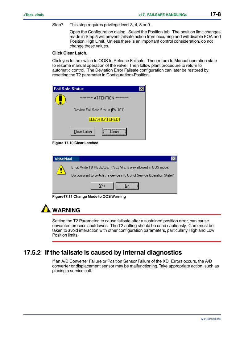
17-8<Toc> <Ind> <17. FAILSAFE HANDLING>
IM 21B04C50-01E
Step7 This step requires privilege level 3, 4, 8 or 9.
Open the Configuration dialog. Select the Position tab. The position limit changesmade in Step 5 will prevent failsafe action from occurring and will disable FOA andPosition High Limit. Unless there is an important control consideration, do notchange these values.
Click Clear Latch.
Click yes to the switch to OOS to Release Failsafe. Then return to Manual operation stateto resume manual operation of the valve. Then follow plant procedure to return toautomatic control. The Deviation Error Failsafe configuration can later be restored byresetting the T2 parameter in Configuration>Position.
Figure 17.10 Clear Latched
Figure17.11 Change Mode to OOS Warning
WARNING
Setting the T2 Parameter, to cause failsafe after a sustained position error, can causeunwanted process shutdowns. The T2 setting should be used cautiously. Care must betaken to avoid interaction with other configuration parameters, particularly High and LowPosition limits.
17.5.2 If the failsafe is caused by internal diagnosticsIf an A/D Converter Failure or Position Sensor Failure of the XD_Errors occurs, the A/Dconverter or displacement sensor may be malfunctioning. Take appropriate action, such asplacing a service call.

App-1
IM 21B04C50-01E
<Toc> <Ind> <APPENDICES>
APPENDICES
Appendix A Glossary and Acronyms
TA01-1.EPS
FAS Fieldbus Access Sublayer
FMS Fieldbus Messaging Service
MIB Management Information Base
SMIB System Management Information Base
MAN Manual mode
RCAS Remote Cascade mode
LO Local Override mode
IMan Initialization manual mode
ROUT Remote output mode
Cas Cascade mode
AUTO Automatic mode
OOS Out of Service mode
Algorithm A set of rules that control the operation of an object through software.
Closed The valve position in which the flow is minimum or zero. See tight shutoff.
AO Analog Output block
Basic Device A Basic Device is any device not having the capability to control communications on an H1 fieldbus segment.
0xf7 See hexadecimal. This is the number 247 represented in hexadecimal notation. The 0x preamble indicates hexadecimal notation.
1.#INF This is the representation of infinity as expressed in IEEE 754 floating point arithmetic. It is used in fieldbus devices to set a parameter to a value that does not interfere with operation, such as for a limit, for example.
ATC Air to close The combination of a single acting actuator and the control valve where the valve is closed when air pressure is applied to the actuator. A spring opens the valve when air pressure is removed.
Capabilities File A Capabilities File describes the communication objects in a fieldbus device. A configuration device can use Device Description (DD) Files and Capabilities Files to configure a fieldbus system without having the fieldbus devices online.
Characteristic The positioner input setpoint command may be selectively modified to provide a desired relationship between setpoint and valve position. In the valve, the relationship between stroke and Cv is also called valve inherent characteristic. It is often adjusted by design, to equal percentage, for example. The positioner characteristic is applied to modify the setpoint to travel relationship of the actuator. The characteristic of the positioner should be chosen to compliment the valve. If the valve is equal percentage, the positioner should be set to linear. If a linear valve is installed the positioner may be set to an equal percentage characteristic to improve flow control. Local display can be used to select the custom characteristic, but cannot adjust the points.
ATO Air to open The combination of a single acting actuator and the control valve where the valve is open when air pressure is applied to the actuator. A spring closes the valve when air pressure is removed.
Communications Stack A Communications Stack is device communications software which provides encoding and decoding of User Layer messages, deterministic control of message transmission, and message transfer.
Compliance voltage The voltage that must be available at the control system output in order to drive the control current through all the resistive devices in series with it.
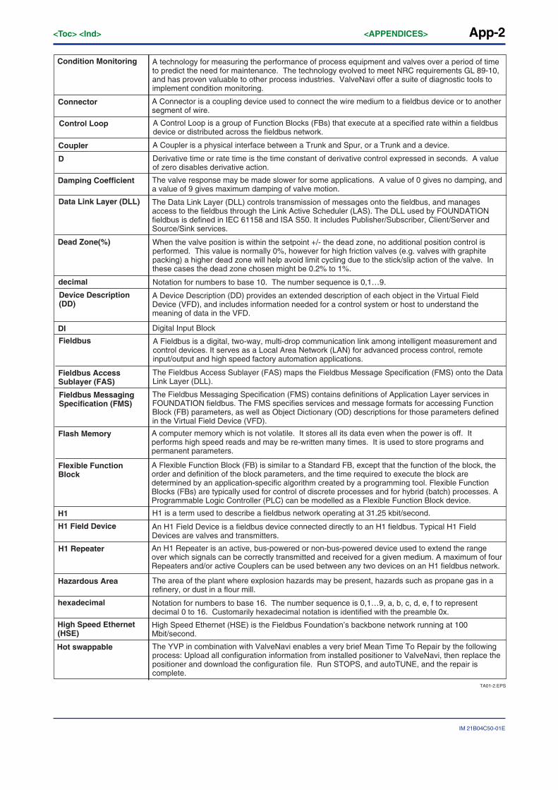
App-2<Toc> <Ind> <APPENDICES>
IM 21B04C50-01E
TA01-2.EPS
Connector A Connector is a coupling device used to connect the wire medium to a fieldbus device or to another segment of wire.
Control Loop A Control Loop is a group of Function Blocks (FBs) that execute at a specified rate within a fieldbus device or distributed across the fieldbus network.
Coupler A Coupler is a physical interface between a Trunk and Spur, or a Trunk and a device.
decimal Notation for numbers to base 10. The number sequence is 0,1…9.
D Derivative time or rate time is the time constant of derivative control expressed in seconds. A value of zero disables derivative action.
Fieldbus Access Sublayer (FAS)
The Fieldbus Access Sublayer (FAS) maps the Fieldbus Message Specification (FMS) onto the Data Link Layer (DLL).
Fieldbus Messaging Specification (FMS)
The Fieldbus Messaging Specification (FMS) contains definitions of Application Layer services in FOUNDATION fieldbus. The FMS specifies services and message formats for accessing Function Block (FB) parameters, as well as Object Dictionary (OD) descriptions for those parameters defined in the Virtual Field Device (VFD).
Hot swappable The YVP in combination with ValveNavi enables a very brief Mean Time To Repair by the following process: Upload all configuration information from installed positioner to ValveNavi, then replace the positioner and download the configuration file. Run STOPS, and autoTUNE, and the repair is complete.
Flexible Function Block
A Flexible Function Block (FB) is similar to a Standard FB, except that the function of the block, the order and definition of the block parameters, and the time required to execute the block are determined by an application-specific algorithm created by a programming tool. Flexible Function Blocks (FBs) are typically used for control of discrete processes and for hybrid (batch) processes. A Programmable Logic Controller (PLC) can be modelled as a Flexible Function Block device.
Flash Memory A computer memory which is not volatile. It stores all its data even when the power is off. It performs high speed reads and may be re-written many times. It is used to store programs and permanent parameters.
hexadecimal Notation for numbers to base 16. The number sequence is 0,1…9, a, b, c, d, e, f to represent decimal 0 to 16. Customarily hexadecimal notation is identified with the preamble 0x.
High Speed Ethernet (HSE)
High Speed Ethernet (HSE) is the Fieldbus Foundation’s backbone network running at 100 Mbit/second.
H1 Repeater An H1 Repeater is an active, bus-powered or non-bus-powered device used to extend the range over which signals can be correctly transmitted and received for a given medium. A maximum of four Repeaters and/or active Couplers can be used between any two devices on an H1 fieldbus network.
Device Description (DD)
A Device Description (DD) provides an extended description of each object in the Virtual Field Device (VFD), and includes information needed for a control system or host to understand the meaning of data in the VFD.
Damping Coefficient The valve response may be made slower for some applications. A value of 0 gives no damping, and a value of 9 gives maximum damping of valve motion.
H1 H1 is a term used to describe a fieldbus network operating at 31.25 kbit/second.
Hazardous Area The area of the plant where explosion hazards may be present, hazards such as propane gas in a refinery, or dust in a flour mill.
DI Digital Input Block
Data Link Layer (DLL) The Data Link Layer (DLL) controls transmission of messages onto the fieldbus, and manages access to the fieldbus through the Link Active Scheduler (LAS). The DLL used by FOUNDATION fieldbus is defined in IEC 61158 and ISA S50. It includes Publisher/Subscriber, Client/Server and Source/Sink services.
Dead Zone(%) When the valve position is within the setpoint +/- the dead zone, no additional position control is performed. This value is normally 0%, however for high friction valves (e.g. valves with graphite packing) a higher dead zone will help avoid limit cycling due to the stick/slip action of the valve. In these cases the dead zone chosen might be 0.2% to 1%.
Fieldbus A Fieldbus is a digital, two-way, multi-drop communication link among intelligent measurement and control devices. It serves as a Local Area Network (LAN) for advanced process control, remote input/output and high speed factory automation applications.
H1 Field Device An H1 Field Device is a fieldbus device connected directly to an H1 fieldbus. Typical H1 Field Devices are valves and transmitters.
Condition Monitoring A technology for measuring the performance of process equipment and valves over a period of time to predict the need for maintenance. The technology evolved to meet NRC requirements GL 89-10, and has proven valuable to other process industries. ValveNavi offer a suite of diagnostic tools to implement condition monitoring.
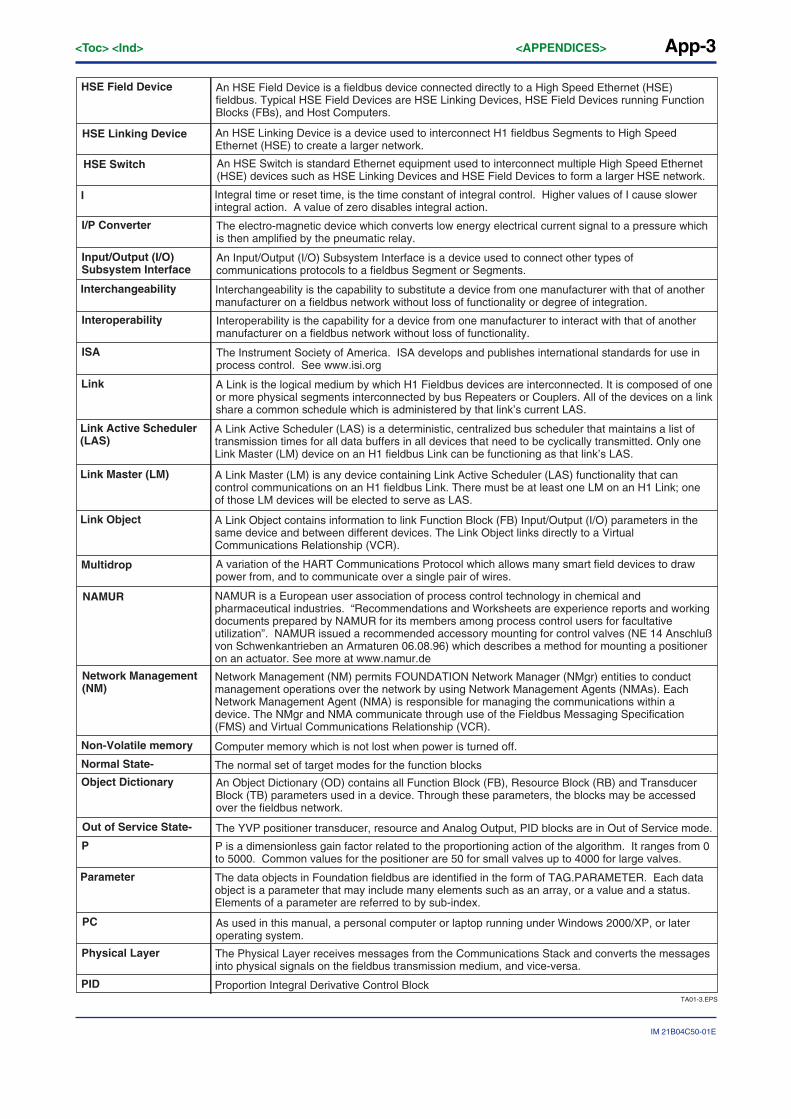
App-3
IM 21B04C50-01E
<Toc> <Ind> <APPENDICES>
TA01-3.EPS
HSE Linking Device An HSE Linking Device is a device used to interconnect H1 fieldbus Segments to High Speed Ethernet (HSE) to create a larger network.
HSE Switch An HSE Switch is standard Ethernet equipment used to interconnect multiple High Speed Ethernet (HSE) devices such as HSE Linking Devices and HSE Field Devices to form a larger HSE network.
NAMUR NAMUR is a European user association of process control technology in chemical and pharmaceutical industries. “Recommendations and Worksheets are experience reports and working documents prepared by NAMUR for its members among process control users for facultative utilization”. NAMUR issued a recommended accessory mounting for control valves (NE 14 Anschluß von Schwenkantrieben an Armaturen 06.08.96) which describes a method for mounting a positioner on an actuator. See more at www.namur.de
P P is a dimensionless gain factor related to the proportioning action of the algorithm. It ranges from 0 to 5000. Common values for the positioner are 50 for small valves up to 4000 for large valves.
Physical Layer The Physical Layer receives messages from the Communications Stack and converts the messages into physical signals on the fieldbus transmission medium, and vice-versa.
I Integral time or reset time, is the time constant of integral control. Higher values of I cause slower integral action. A value of zero disables integral action.
Network Management(NM)
Network Management (NM) permits FOUNDATION Network Manager (NMgr) entities to conduct management operations over the network by using Network Management Agents (NMAs). Each Network Management Agent (NMA) is responsible for managing the communications within a device. The NMgr and NMA communicate through use of the Fieldbus Messaging Specification (FMS) and Virtual Communications Relationship (VCR).
Non-Volatile memory Computer memory which is not lost when power is turned off.
Out of Service State- The YVP positioner transducer, resource and Analog Output, PID blocks are in Out of Service mode.
PID Proportion Integral Derivative Control Block
Normal State- The normal set of target modes for the function blocks
PC As used in this manual, a personal computer or laptop running under Windows 2000/XP, or later operating system.
HSE Field Device An HSE Field Device is a fieldbus device connected directly to a High Speed Ethernet (HSE) fieldbus. Typical HSE Field Devices are HSE Linking Devices, HSE Field Devices running Function Blocks (FBs), and Host Computers.
I/P Converter The electro-magnetic device which converts low energy electrical current signal to a pressure which is then amplified by the pneumatic relay.
Input/Output (I/O) Subsystem Interface
An Input/Output (I/O) Subsystem Interface is a device used to connect other types of communications protocols to a fieldbus Segment or Segments.
Interchangeability Interchangeability is the capability to substitute a device from one manufacturer with that of another manufacturer on a fieldbus network without loss of functionality or degree of integration.
Interoperability Interoperability is the capability for a device from one manufacturer to interact with that of another manufacturer on a fieldbus network without loss of functionality.
ISA The Instrument Society of America. ISA develops and publishes international standards for use in process control. See www.isi.org
Link A Link is the logical medium by which H1 Fieldbus devices are interconnected. It is composed of one or more physical segments interconnected by bus Repeaters or Couplers. All of the devices on a link share a common schedule which is administered by that link’s current LAS.
Object Dictionary An Object Dictionary (OD) contains all Function Block (FB), Resource Block (RB) and Transducer Block (TB) parameters used in a device. Through these parameters, the blocks may be accessed over the fieldbus network.
Parameter The data objects in Foundation fieldbus are identified in the form of TAG.PARAMETER. Each data object is a parameter that may include many elements such as an array, or a value and a status. Elements of a parameter are referred to by sub-index.
Link Active Scheduler (LAS)
A Link Active Scheduler (LAS) is a deterministic, centralized bus scheduler that maintains a list of transmission times for all data buffers in all devices that need to be cyclically transmitted. Only one Link Master (LM) device on an H1 fieldbus Link can be functioning as that link’s LAS.
Link Master (LM) A Link Master (LM) is any device containing Link Active Scheduler (LAS) functionality that can control communications on an H1 fieldbus Link. There must be at least one LM on an H1 Link; one of those LM devices will be elected to serve as LAS.
Link Object A Link Object contains information to link Function Block (FB) Input/Output (I/O) parameters in the same device and between different devices. The Link Object links directly to a Virtual Communications Relationship (VCR).
Multidrop A variation of the HART Communications Protocol which allows many smart field devices to draw power from, and to communicate over a single pair of wires.
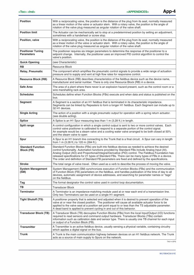
App-4<Toc> <Ind> <APPENDICES>
IM 21B04C50-01E
TA01-4.EPS
The Actuator can be mechanically set to stop at a predetermined position by setting an adjustment, sometimes with a handwheel or screw stop.
Standard Function Block (FB)
Standard Function Blocks (FBs) are built into fieldbus devices as needed to achieve the desired control functionality. Automation functions provided by Standard FBs include Analog Input (AI), Analog Output (AO) and Proportional/Integral/Derivative (PID) control. The Fieldbus Foundation has released specifications for 21 types of Standard FBs. There can be many types of FBs in a device. The order and definition of Standard FB parameters are fixed and defined by the specifications.
Trunk A Trunk is the main communication highway between devices on an H1 fieldbus network. The Trunk acts as a source of main supply to Spurs on the network.
Tag The formal designator the control valve used in control loop documentation.
Quick Opening (see Characteristic)
RB Resource Block
TB Transducer Block
Transmitter A Transmitter is an active fieldbus device, usually sensing a physical variable, containing circuitry which applies a digital signal on the bus.
Position With a reciprocating valve, the position is the distance of the plug from its seat, normally measured as a linear motion of the valve or actuator stem. With a rotary valve, the position is the angle of rotation of the valve plug measured as angular rotation of the valve shaft.
Position, valve
Position limit
The area of a plant where there never is an explosion hazard present, such as the control room or a wire marshalling rack area.
Safe Area
The action of a position with a single pneumatic output for operation with a spring return actuator. (see double acting).
Single Acting
Schedules define when Function Blocks (FBs) execute and when data and status is published on the bus.
Schedules
A Segment is a section of an H1 fieldbus that is terminated in its characteristic impedance. Segments can be linked by Repeaters to form a longer H1 fieldbus. Each Segment can include up to 32 H1 devices.
Segment
A control configuration in which a single control output is sent to two or more control valves. Each control valve positioner is calibrated to respond to a separate portion of the control signal. An example would be a steam valve and a cooling water valve arranged to be both closed at 50% and the steam valve to open
Split range
A positioner property that is selected and adjusted when it is desired to prevent operation of the valve at or near the closed position. The positioner will cause all available actuator force to be applied to the valve seat at a position set point equal to or less than the TS adjustable parameter. A dead band is applied to prevent cycling in and out of this behavior.
Tight Shutoff (TS)
A Transducer Block (TB) decouples Function Blocks (FBs) from the local Input/Output (I/O) functions required to read sensors and command output hardware. Transducer Blocks (TBs) contain information such as calibration date and sensor type. There is usually one TB channel for each input or output of a Function Block (FB).
Transducer Block (TB)
System Management (SM) synchronizes execution of Function Blocks (FBs) and the communication of Function Block (FB) parameters on the fieldbus, and handles publication of the time of day to all devices, automatic assignment of device addresses, and searching for parameter names or "tags" on the fieldbus.
System Management (SM)
A Splice is an H1 Spur measuring less than 1 m (3.28 ft.) in length. Splice
The total range of valve travel. Often used as a verb to describe the process of moving the valve.Stroke
A Spur is an H1 branch line connecting to the Trunk that is a final circuit. A Spur can vary in length from 1 m (3.28 ft.) to 120 m (394 ft.).
Spur
A Terminator is an impedance-matching module used at or near each end of a transmission line. Only two Terminators can be used on a single H1 segment.
Terminator
With a reciprocating valve, the position is the distance of the plug from its seat, normally measured as a linear motion of the valve or actuator stem. With a rotary valve, the position is the angle of rotation of the valve plug measured as angular rotation of the valve shaft.
Positioner Tuning Parameters
The positioner requires six integer parameters to determine the response of the positioner to a setpoint change. Internally, the positioner uses an improved PID control algorithm to control the valve’s position.
Relay, Pneumatic
Resource Block (RB)
The component which amplifies the pneumatic control signals to provide a wide range of actuation pressure and to supply and vent at high flow rates for responsive control.
A Resource Block (RB) describes characteristics of the fieldbus device such as the device name, manufacturer and serial number. There is only one Resource Block (RB) in a device.

App-5
IM 21B04C50-01E
<Toc> <Ind> <APPENDICES>
TA01-5.EPS
The User Layer provides scheduling of Function Blocks (FBs), as well as Device Descriptions (DDs) which allow the host system to communicate with devices without the need for custom programming.
VCR See Virtual Communication Relationship
User Application The User Application is based on “blocks,” including Resource Blocks (RBs), Function Blocks (FBs) and Transducer Blocks (TBs), which represent different types of application functions.
User Layer
The full featured Yokogawa software for diagnostics, calibration, and configuration of Foundation fieldbus positioner, YVP.
ValveNavi
A Virtual Field Device (VFD) is used to remotely view local device data described in the object dictionary. A typical device will have at least two Virtual Field Devices (VFDs).
Virtual Field Device (VFD)
Configured application layer channels that provide for the transfer of data between applications. FOUNDATION fieldbus decribes three types of VCRs: Publisher/Subscriber, Client/Server, and Source/Sink.
Virtual Communication Relationship (VCR)
A Standard common in Europe for mounting positioners and accessories on rotary valve actuators.VDE/VDI 3845
See Virtual Field DeviceVFD

App-6<Toc> <Ind> <APPENDICES>
IM 21B04C50-01E
Appendix B Configuring DI Blocks to TB ChannelsThere are two DI (discrete input) blocks in YVP. They are used to communicate the state ofinternal (software) limit switches. The DI modes are displayed in IVI and the internalvariables can be viewed with the Query service.
To activate the DI blocks, each block must be scheduled (though not necessarily linked)and each must be configured to the correct channel in the TB. In an FB configurator set theDI channel parameter. Channel 2 should be assigned to the High limit switch DI1, andchannel 3 should be assigned to the low limit switch, DI2.
App-7
IM 21B04C50-01E
<Toc> <Ind> <APPENDICES>
Appendix C Setting a Failsafe StrategyThe user must design a strategy for safe handling of fault conditions that will be safe andeffective for each control valve. Several levels of failsafe action can be configured usingYVP and ValveNavi to support the safety strategy.
As levels of safety are increased, more actions are required to restart a system that hasgone into failsafe. The most secure level will cause the positioner to close the valve andcause it to remain closed until an operator manually reopens the valve. In the least securelevel, the valve will close and will reopen as soon as the cause of the failsafe event hascleared.
On non-critical processes, the highest level of security may cause excessive nuisanceshutdowns. In these cases, it may be preferable to allow the valve to restart after failsafe.
When a critical process that has the potential to release toxic substances or to result in anaccident, it may be necessary to force full shutdown with manual restart.
WARNING
Do not set Position Lower Limit equal to or larger than the Deviation Error Band value. It willnot be possible to clear the Failsafe condition.
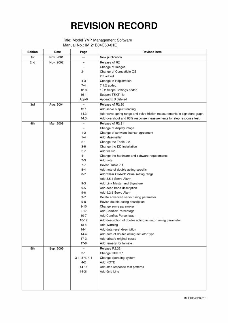
IM 21B04C50-01E
REVISION RECORDTitle: Model YVP Management SoftwareManual No.: IM 21B04C50-01E
Edition Date Page Revised Item
1st Nov. 2001 — New publication
2nd Nov. 2002 – Release of R2
– Change of Images
2-1 Change of Compatible OS
2.3 added
4-3 Change in Registration
7-4 7.1.2 added
12-3 12.2 Scope Settings added
16-1 Support TEXT file
App-6 Appendix B deleted
3rd Aug. 2004 – Release of R2.20
12.1 Add servo output trending.
14.3 Add valve spring range and valve friction measurements in signature graph.
14.3 Add overshoot and 86% response measurements for step response test.
4th Mar. 2008 – Release of R2.31
– Change of display image
1-2 Change of software license agreement
1-4 Add Masoneilan
2-1 Change the Table 2.2
3-6 Change the DD installation
3.7 Add file No.
4-1 Change the hardware and software requirements
7-3 Add note
7-7 Revise Table 7.1
8-4 Add note of double acting specific
8-7 Add “Near Closed” Value setting range
Add 8.5.4 Servo Alarm
9-3 Add Link Master and Signature
9-5 Add dead band description
9-6 Add 9.2.5 Servo Alarm
9-7 Delete advanced servo tuning parameter
9-8 Revise double acting description
9-10 Change some parameter
9-17 Add Camflex Percentage
10-7 Add Camflex Percentage
10-12 Add description of double acting actuator tuning parameter
13-4 Add Warning
14-1 Add data reset description
14-4 Add note of double acting actuator type
17-3 Add failsafe original cause
17-8 Add remedy for failsafe
5th Sep. 2009 – Release R2.32
2-1 Change table 2.1
3-1, 3-4, 4-1 Change operating system
4-2 Add NOTE
14-11 Add step response test patterns
14-21 Add Grid Line