user’s manual of board et-mini isd2548: … et-mini isd2548 is used to record sound and playback...
TRANSCRIPT
User’s Manual of Board ET-MINI ISD2548: PLAY&RECORD MESSAGE
www.etteam.com -1-
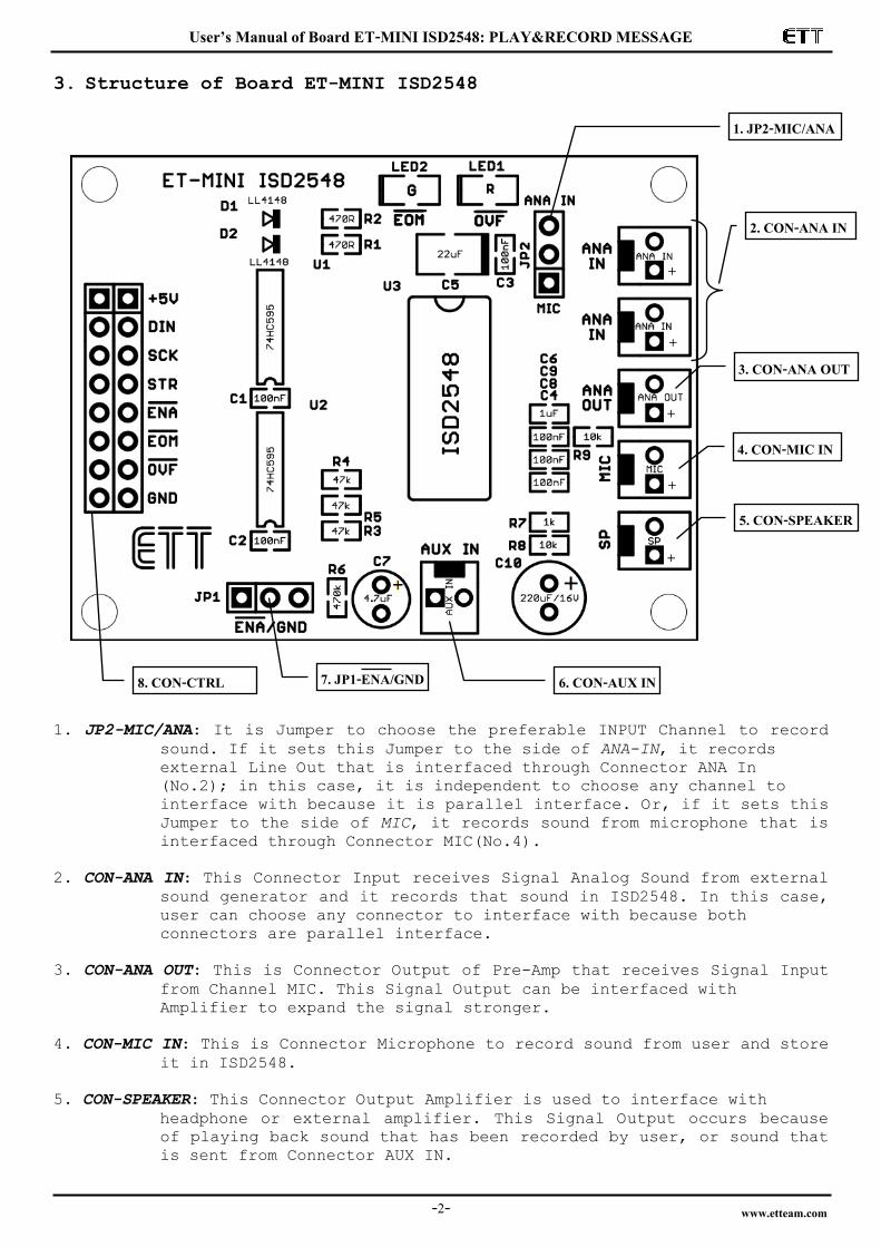
ISD2548S
2816
VCCD
VCCA
VSSD
VSSA
12131415 20 21191817
SP+SP-
ANA INANA OUT
MIC REF
MIC
AGC
12345678910
23 24 272522 26
AUX IN11
A0/M0
A1/M1
A2/M2
A3/M3
A4/M4
A5/M5
A6/M6A7A8 NC
CE PD P/REOM
OVF
XCLK
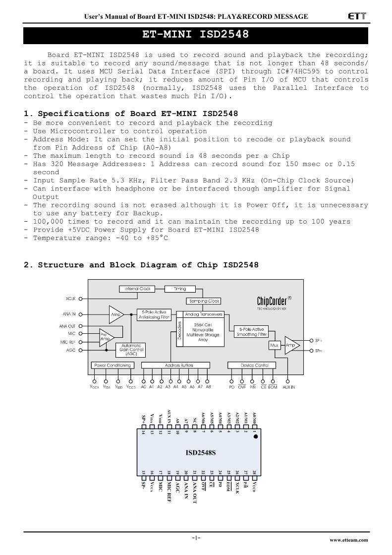
Board ET-MINI ISD2548 is used to record sound and playback the recording;
it is suitable to record any sound/message that is not longer than 48 seconds/
a board. It uses MCU Serial Data Interface (SPI) through IC#74HC595 to control
recording and playing back; it reduces amount of Pin I/O of MCU that controls
the operation of ISD2548 (normally, ISD2548 uses the Parallel Interface to
control the operation that wastes much Pin I/O).
1. Specifications of Board ET-MINI ISD2548 - Be more convenient to record and playback the recording - Use Microcontroller to control operation - Address Mode: It can set the initial position to recode or playback sound
from Pin Address of Chip (A0-A8) - The maximum length to record sound is 48 seconds per a Chip - Has 320 Message Addresses: 1 Address can record sound for 150 msec or 0.15
second
- Input Sample Rate 5.3 KHz, Filter Pass Band 2.3 KHz (On-Chip Clock Source) - Can interface with headphone or be interfaced though amplifier for Signal
Output
- The recording sound is not erased although it is Power Off, it is unnecessary to use any battery for Backup.
- 100,000 times to record and it can maintain the recording up to 100 years - Provide +5VDC Power Supply for Board ET-MINI ISD2548 - Temperature range: -40 to +85°C
2. Structure and Block Diagram of Chip ISD2548
ET-MINI ISD2548
User’s Manual of Board ET-MINI ISD2548: PLAY&RECORD MESSAGE
www.etteam.com -2-
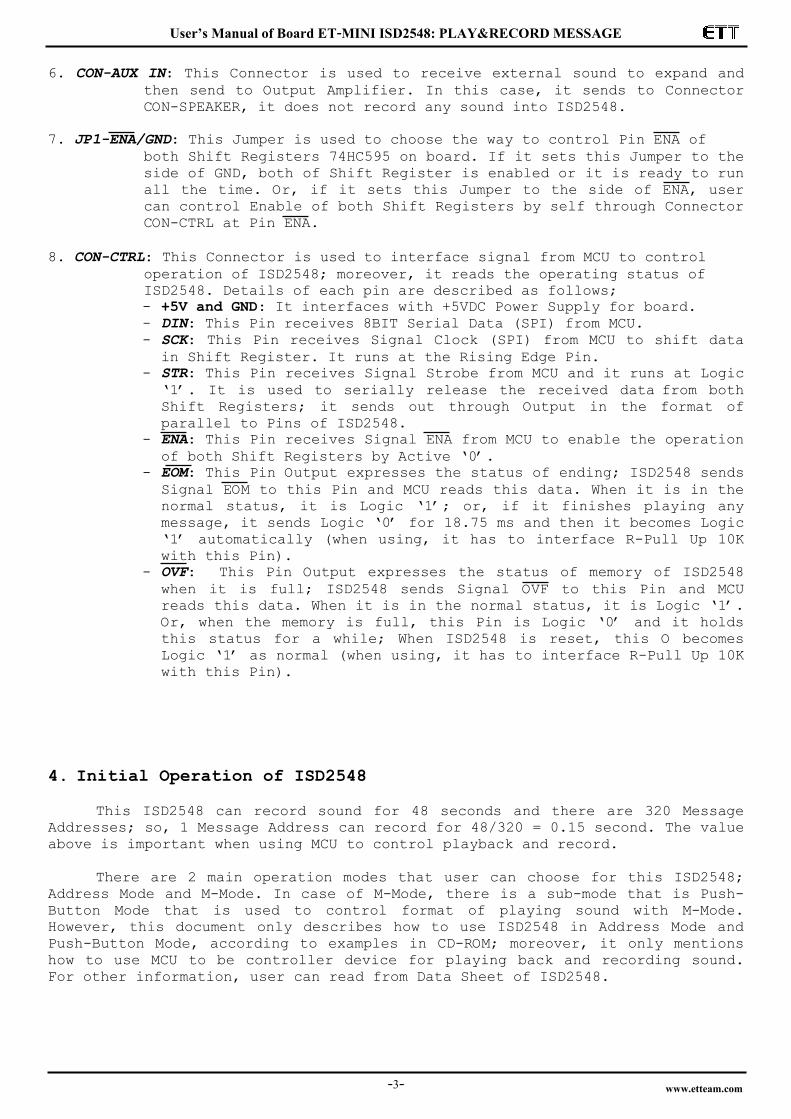
3. Structure of Board ET-MINI ISD2548
1. JP2-MIC/ANA: It is Jumper to choose the preferable INPUT Channel to record
sound. If it sets this Jumper to the side of ANA-IN, it records
external Line Out that is interfaced through Connector ANA In
(No.2); in this case, it is independent to choose any channel to
interface with because it is parallel interface. Or, if it sets this
Jumper to the side of MIC, it records sound from microphone that is
interfaced through Connector MIC(No.4).
2. CON-ANA IN: This Connector Input receives Signal Analog Sound from external
sound generator and it records that sound in ISD2548. In this case,
user can choose any connector to interface with because both
connectors are parallel interface.
3. CON-ANA OUT: This is Connector Output of Pre-Amp that receives Signal Input
from Channel MIC. This Signal Output can be interfaced with
Amplifier to expand the signal stronger.
4. CON-MIC IN: This is Connector Microphone to record sound from user and store
it in ISD2548.
5. CON-SPEAKER: This Connector Output Amplifier is used to interface with
headphone or external amplifier. This Signal Output occurs because
of playing back sound that has been recorded by user, or sound that
is sent from Connector AUX IN.
3. CON-ANA OUT
4. CON-MIC IN
2. CON-ANA IN
1. JP2-MIC/ANA
8. CON-CTRL
+
+
+
+
+
6. CON-AUX IN 7. JP1-ENA/GND
5. CON-SPEAKER
User’s Manual of Board ET-MINI ISD2548: PLAY&RECORD MESSAGE
www.etteam.com -3-
6. CON-AUX IN: This Connector is used to receive external sound to expand and
then send to Output Amplifier. In this case, it sends to Connector
CON-SPEAKER, it does not record any sound into ISD2548.
7. JP1-ENA/GND: This Jumper is used to choose the way to control Pin ENA of
both Shift Registers 74HC595 on board. If it sets this Jumper to the
side of GND, both of Shift Register is enabled or it is ready to run
all the time. Or, if it sets this Jumper to the side of ENA, user
can control Enable of both Shift Registers by self through Connector
CON-CTRL at Pin ENA.
8. CON-CTRL: This Connector is used to interface signal from MCU to control
operation of ISD2548; moreover, it reads the operating status of
ISD2548. Details of each pin are described as follows;
- +5V and GND: It interfaces with +5VDC Power Supply for board. - DIN: This Pin receives 8BIT Serial Data (SPI) from MCU. - SCK: This Pin receives Signal Clock (SPI) from MCU to shift data
in Shift Register. It runs at the Rising Edge Pin. - STR: This Pin receives Signal Strobe from MCU and it runs at Logic
„1‟. It is used to serially release the received data from both Shift Registers; it sends out through Output in the format of
parallel to Pins of ISD2548. - ENA: This Pin receives Signal ENA from MCU to enable the operation
of both Shift Registers by Active „0‟. - EOM: This Pin Output expresses the status of ending; ISD2548 sends
Signal EOM to this Pin and MCU reads this data. When it is in the
normal status, it is Logic „1‟; or, if it finishes playing any
message, it sends Logic „0‟ for 18.75 ms and then it becomes Logic
„1‟ automatically (when using, it has to interface R-Pull Up 10K
with this Pin). - OVF: This Pin Output expresses the status of memory of ISD2548
when it is full; ISD2548 sends Signal OVF to this Pin and MCU
reads this data. When it is in the normal status, it is Logic „1‟.
Or, when the memory is full, this Pin is Logic „0‟ and it holds
this status for a while; When ISD2548 is reset, this O becomes
Logic „1‟ as normal (when using, it has to interface R-Pull Up 10K
with this Pin).
4. Initial Operation of ISD2548
This ISD2548 can record sound for 48 seconds and there are 320 Message
Addresses; so, 1 Message Address can record for 48/320 = 0.15 second. The value
above is important when using MCU to control playback and record.
There are 2 main operation modes that user can choose for this ISD2548;
Address Mode and M-Mode. In case of M-Mode, there is a sub-mode that is Push-
Button Mode that is used to control format of playing sound with M-Mode.
However, this document only describes how to use ISD2548 in Address Mode and
Push-Button Mode, according to examples in CD-ROM; moreover, it only mentions
how to use MCU to be controller device for playing back and recording sound.
For other information, user can read from Data Sheet of ISD2548.
User’s Manual of Board ET-MINI ISD2548: PLAY&RECORD MESSAGE
www.etteam.com -4-
4.1) Address Mode
This operation mode uses Pin A0-A8 to setup the preferable Address to
playback and record sound. Pin A7 and A8 are used to choose operation mode; in
this case, it has to set it to be „00‟ or „01‟ or „10‟, and ISD2548 can run in
this operation mode. There are 320 Message Addresses of ISD2548; so, it can
refer to Address position in the range of 0-319 or 000000000b - 100111111b
(0x000-0x13F). In this case, the highest Address position still sets Bit A7 and
A8 to be in the range of 3 statuses; 00, 01, 10 as mentioned above. Remember,
if user requires using this operation mode, the Address position that is
referred to record and playback sound is not exceeded 0x31F only; and it always
runs in this operation mode. There are 3 Pins that are used to control
recording and playing back as follows;
1) CE: This Pin receives Signal Pulse Active Low (normally, it should be
High); it controls Start Playback or Start Record.
2) PD: This Pin receives Signal Pulse Active High (normally, it should be
Low); it resets ISD2548. If it is playing back or recording, it
stops immediately; moreover, the position of Message Address is
pointed to the current position that user has set at Pin A0-A8.
3) P/R: This Pin is used to record or playback. If it is High, it
playbacks; or, if it is Low, it records.
There are 2 Pins that are used to express the operating status of ISD2548 as
follows; 1) EOM: Every time after it finishes playing message, ISD2548 sends
Signal Pulse Low with 18.75ms Width to this Pin to notify user to
know that it finishes playing the message and the Signal Pulse EOF
becomes High automatically.
2) OVF: This Signal is Pulse Low when the memory space of ISD2548 is full, or it records sound until the memory of ISD2548 is full as
well. This Signal is Low until it resets ISD2548 at Pin PD, and then
this Signal becomes High.
4.1.1) How to Record in Address Mode
1) Set initial Address that user prefers to record sound at Pin A0-A8; in this case, it can set Address in the range of 0x000-0x13F. For example,
if user records sound at Address 0x005, it has to set Pin A0,A2 = ‘1’,
and it sets the rest of Pin Address to be ‘0’.
2) Set Pin PD to be Low; it exits from status of Reset and ISD2548 is ready to run.
3) Set Pin P/R to be Low; it chooses record mode. 4) Set Pin CE to be Low and hold it for a while; next, user can input the
preferable message to recode and it starts recording the message into the
specific Message Address in step No.1. When the Message Address records
the message until it is full, it automatically increases the new Address
if it still records (CE is still LOW). As mentioned above, 1 Address can
record for 0.15 second at the maximum. If it records message until the
memory space of ISD2548 is full, it sends Signal Overflow as Pulse Low
through Pin OVF to notify user to know that the memory is full; so, any
new incoming sound is ineffective.
5) When it stops recording, user has to set Pin CE to be High and Signal EOM is recorded into the address memory next to the message that has been
recorded previously. When user requires recording other messages into the
next address, it should return to step no.2 and repeats processes.
Moreover, user should consider that any Address that is used to record
new message must not overlap the Address of previous message; otherwise
it makes some previous message lost.
If user records several short messages into the same ISD2548, user can

User’s Manual of Board ET-MINI ISD2548: PLAY&RECORD MESSAGE
www.etteam.com -5-
set the initial Address position to record, but user does not know where the
exact Address position of the recorded message ends; so, it is difficult to set
Address for the next message. In this case, we would like to suggest user to
record each message by setting equal period and then measure time taken. When
it records message until it reaches the specific time, it stops automatically
and user can set the initial Address position for the next message, without any
overlap (please read more examples in CD-ROM from examples “Ex1_Play_Record”).
This is an example when user requires recording short message that is not
longer than 2 seconds; because 1 Address can record message for 0.15 second as
mentioned in the specification of ISD2548 above, so it needs to use Address
that equals 2/0.15 ~ 14 Address for 1 message. If it starts recording the first
message at Address 0; the second message has to record at Address 15; the third
message has to record at Address 30, and so on. When it starts recording
message at Address 0 and user adds more 14 Addresses, the message must end at
the position that is not greater than Address 13. Next, user has to add 1 more
Address for Signal EOM; so, the first message must be ended at Address 14 and
the second message must be started at Address 15. In this case, don‟t forget to
add 1 more Address in each message to record Signal EOM, otherwise Signal EOM
will be recorded and overlapped the Address position that has been recorded
previously and it cannot separate the end of each message while playing back.
In summary, this is the method to calculate amount of the used Address,
according with the preferable length for each message;
Amount of the used Address = [length of message(second)/0.15(second)]+1 (EOM Address)
When user keeps writing program until it reaches the step No.4 that is CE=Low,
it starts recording message. In this case, it should set Time Delay for 2
seconds, according to the length of message. When Time Delay 2 second is
completed, user can go to step No.6 to stop recording the message (CE=High).
4.1.2) How to Playback in Address Mode
1) Set initial Address that user requires playing back at Pin A0-A8; in this
case, it can set Address in the range of 0x000-0x13F. For example, if it
starts playing back at Address 0x005, it has to set Pin A0,A2=’1’, and it
sets the rest of Pin Address t be „0‟.
2) Set Pin PD to be Low; it exits from status of Reset and ISD2548 is ready to run.
3) Set Pin P/R to be High; it chooses Playback mode. 4) Set Pin CE. When setting this Pin CE, it has 2 effects on the Playback
mode as follows;
- Set and hold Pin CE to be Low (it normally is High); the message position
that is pointed by the specified Pin Address in the step No.2 will start
playing instantly. While plying back, Pin EOM is High. When it finishes
playing message, ISD2548 sends Signal Low to Pin EOM for 18.75ms and then
it becomes High again; user can use this pin to check the end of playing
message. When the first message ends, it starts playing the second and
third message continuously and it always sends out Signal EOM Logic Low
when it ends of playing each message. It continues playing messages until
Pin CE is set to be High, or it plays until it reaches the end of Address
of Memory ISD2548, it stops. If Pin CE is set to be High while playing
message, the message that is playing continues playing until it ends, and
it stops. When it stops playing, it sets Pin CE to be Low again; in this
case, the first message that is pointed by Pin Address in step No.1 re-
starts playing instantly.
- Set Pin CE in the format of Push, it means that it sets Pin CE from High
to Low and then set it to be High instantly, the message that is pointed
by the specified Pin Address in step No.1 starts playing instantly. While
playing message, Pin EOM is High; when it finishes, ISD2548 sends Signal

User’s Manual of Board ET-MINI ISD2548: PLAY&RECORD MESSAGE
www.etteam.com -6-
Logic Low to Pin EOM for 18.75ms and it becomes High again and it
finishes playing the message. If user requires playing the next message,
it has to check if the Signal EOM becomes High, and then user can return
and repeat steps from No.1 to play the next message.
5) If user stops while playing message; it sets Pin PD to be high and it makes ISD2548 is in status of Reset.
4.2) Operation in Push-Button Mode (sub-mode of M-Mode)
When using this operation mode, it has to set Pin A6,A7,A8 to be High;
function of Pin A0-A5 is changed to Pin M0-M5 and each pin has different
function. Normally, when it is interfaced with Pin M0-M5, it should set Full
Down; if user requires running any pin according to its function, it only sets
that pin to be High. As mentioned above, user can set the preferable pin by
Active to High; moreover, user has to set other Pin Controls together, it
depends on the operating format of each pin. We do not describe in this
section, please read more information from Data Sheet.
The operation of this Push-Button Mode is to record and playback by using
Pin Control CE, D, P/R and EOM; its function is similar to Address Mode.
Function of each pin is described below; 1) Pin CE: This Pin receives Signal Pulse Active Low (High Low); it is
used to control START or PAUSE for playback and record. It starts
playing back or recording message when this Pin receives the Signal
Pulse Low; while playing back if it sends the Signal Pulse Low to this
pin before Signal EOM or OVF happens, it temporarily stops (PAUSE)
instantly. However, if it sends this Signal Pulse Low to this pin again,
it returns to playback message and it starts at the paused position.
2) Pin PD: This Pin receives Signal Pulse Active High (Low High); it is
used to control STOP or RESET for playback and record. When the status
of STOP/RESET happens, it stops playing or recording message instantly,
and Address Pointer of Message is reset to be 0x000 again. If user
commands to play or record new message, it always starts playing or
recording at Address 0x000 again. Every time this Pin is Active, the
status of STOP/RESET always happens and Pointer Address always points to
the initial Address of 0x000 as well.
3) Pin P/R: This Pin is used to choose operation modes between Record and Playback. If this Pin is set to be High, it chooses „Playback‟ Mode; or,
if this Pin is set to be Low, it chooses „Record‟ Mode.
4) Pin EOM: This Pin is Output that shows operating status of playback and record; in this case, it can interface with LED to shows the operating
status. It shows the status of High when it is playback or record; or,
it shows the status of Low when it is not playback or record. When
managing message in this Mode, user cannot refer to any Address directly
unlike Address Mode; in this case, it uses the way to control function
of Pin M0-M5 to manage message instead. When it starts running, or it
resets, or it changes function from Record to Playback or from Playback
to Record, the initial Address that is referred internal ISD2548 of this
mode is always Address 0x000; it does not depend on Pin A0-A8. Next, we
will mention the procedure for record and playback in this mode.
User’s Manual of Board ET-MINI ISD2548: PLAY&RECORD MESSAGE
www.etteam.com -7-
4.2.1) Procedures for Recode in Push-Button Mode
1) Set Pin A6-A8 to be High to choose Push-Button Mode; and it should set Full Down for Pin A0-A5 or set these pins to be Low.
2) Set Pin PD to be Low, it exits from the status of Reset and ISD2548 is ready to run.
3) Set Pin P/R to be Low, it chooses Record mode. 4) Set Pin CE in the format of Pulse Low; it means that it sets Pin CE from
High to Low and then set it to High again, it starts recording. The
status of Pin EOM that normally is Low changes to High, it shows status
of record and it starts recoding at Address 0x000.
5) When Pin CE receives Pulse Low again, it stops recording message
instantly; the signal at Pin EOM changes from High to Low to show that it
stops recording. Address Pointer of the memory has not been cleared yet
after the end of record. Every time EOM Maker will be stored in the
Address memory after the currently recorded message; this EOM marker is
an identifier for the end of each message. Meanwhile, if Pin P/R is set
to be High for Playback and CE receives Signal Pulse Low, the Playback
should be started at Address 0x000. On the other hand, if Pin P/R is set
to be Low for Record again and Pin PD still is Low, it starts recording
into the Address position after the recent Address position of Playback. If it records message until the memory of ISD2548 is full, Signal at
Pin EOM changes from High to Low automatically; it notifies user to know
that the record ends and the memory is full, without sending any Pulse
Low to Pin CE by oneself to stop recording as usual.
6) After it stops recording if user still provides Signal Pulse Low to Pin CE, it starts recording again; it starts recording after the Address
position that records EOM Marker of the previously recorded message.
Moreover, the status of Pin EOM is changed from Low to High to show
status of Record and the next message will be recorded in the continuous
Address position respectively; in this case, it returns and repeats step
No.5 and No.6, alternately.
To record each message, after user has done step from No.1 to No.4
completely, user has to do step No.5 and step No.6 alternately. Finally,
messages will be recorded in the continuous Address positions and each message
is separated by EOM Marker to be the identifier of the end. While recording or
after recording any message completely but ISD2548 is reset by any cause; for
example, PD is set to be High and then become Low again. After Reset if user
requires recording any message again, it always returns to the Address 0x000 to
record; it does not record any message after the Address position of the
previously recorded message. It means that if ISD2548 is reset, Address Pointer
of the memory is also reset. Moreover, if it records new message, it always
overlaps the old message; or, if the new message is shorter than the old one,
the old recorded message still remains.
4.1.2 Procedures for Playback in Push-Button Mode
1) Set Pin A6-A8 to be High to choose Push-Button Mode; other Pin A0-A5 should set Full Down or Low.
2) Set Pin PD to be Low; it exits from status of Reset and ISD2548 is ready to run.
3) Set Pin P/R to be High; it chooses Playback mode. 4) Set Pin CE in the format of Pulse Low; in this case, it sets Pin CE from
High Low and then set it to be High again, it starts playing back the
message. Normally, the status of Pin EOM is Low and it becomes High to
show status of Playback. It starts playing back at Address 0x000. When it
ends of playing back any message, it stops automatically and status of
Pin EOM changes from High to Low.
User’s Manual of Board ET-MINI ISD2548: PLAY&RECORD MESSAGE
www.etteam.com -8-
5) If it sends more Pulse Low to Pin CE while playing any message, it
temporarily stops (PAUSE); Address Pointer is not reset and signal at Pin
EOM is changed from High to Low. While it is in the status of PAUSE if
user sets Pin P/R to be Low for Record and the status of Pin PD is still
the same; it starts recording when user sends Signal Pulse Low to Pin CE,
and it stops when user sends Signal Pulse Low to Pin CE again. The new
message will be recorded after the Address Pointer of the recently
recorded Message; it does not start at Address Pointer 0x000.
6) Refer to the step No.4 above; after the end of playing any message, it stops automatically. If user requires playing the next message, it has to
send Signal Pulse Low to Pin CE again, the next message after the first
message will be played instantly. In this case, every time user sends
Signal Pulse Low to Pin CE after the end of the previous message, the
next message always played until it overflows or Pin PD is set to be
High, and then Address Pointer is reset to be 0x000. When user requires
playing back, it has to return step No.1; starts playing message at the
Address 0x000 again.
Use can set trick of playback in this Pulse-Button Mode such as Skip
Message, Repeat the first message; in this case, it uses Pin M0-M5 to set
tricks as example below;
- How to use Pin M3 to repeat message at Address Pointer 0x000 (only repeat the
first message)
If user to set Repeat message, it can set value while playing back any
message or not playback; in this case, it has to set Pin PD to be Low and Pin
P/R must be still High. If user requires repeating the first message, it has to
set Pin M3 that normally is Low to be High first and provides Signal Pulse Low
to Pin CE, the first message is playback. When it finishes playing the first
message completely, it repeats the first message instantly.
If user requires exiting from repeat message, it has to set Pin M3 from
High to Low and then provide Signal Pulse Low to Pin CE; it will exit from
repeat message instantly.
To set repeat message or exit from repeat message, if user sends Signal
Pulse Low to Pin CE while is playing back, it temporarily stops playing back
(PAUSE) as well; so, it has to send the second Signal Pulse Low to Pin CE again
or the second wave instead. In this case, it continues playing the current
message until it finishes, and then it restarts playing back if set MP3 to
repeat; or, it stops instantly is it sets MP3 to exit from repeat.
- How to use Pin M0 to skip unwanted message
To skip any message, it can set value while playing back or not playback
any message; in this case, it has to set Pin PD to be Low and Pin P/R is still
to be High. When user requires skipping any unwanted message, it has to set Pin
M0 that is normally Low to High, and then provides Signal Pulse Low to Pin CE;
in this case, amount of unwanted message to skip and Signal Pulse Low that is
sent to Pin CE must be equal. Next, it has to set Pin M0 from High to Low, and
provides Signal Pulse Low to Pin CE again; the message after the skipped
message will be played back instantly.
User’s Manual of Board ET-MINI ISD2548: PLAY&RECORD MESSAGE
www.etteam.com -9-
5. How to use Board ET-MINI ISD2548
As mentioned in section 4 above, all describe how to control the
operation at Pin I/O of ISD2548 directly. In case of Board ET-MINI ISD 2548,
there is Shift Register #74HC595 that is interfaced between ISD2548 to reduce
amount of Pin I/O for controlling operation of ISD2548. This Shift Register is
used to send/receive data in the format of Serial-In/Parallel-Out that uses SPI
Interface; so, it has to use MCU to be intermediate between receiving and
sending data to control the operation of ISD2548. In this case, Data that is
sent out to control the operation must accord with the process of ISD2548 as
mentioned in the section 4 above.
5.1) How to send data as SPI
First of all, user should understand the operation of sending/receiving
data in the format of SPI first. This Shift Register number is 8-Bit or 1 Byte
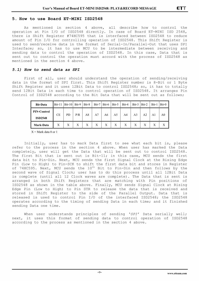
Shift Register and it uses 12Bit Data to control ISD2548; so, it has to totally
send 12Bit Data in each time to control operation of ISD2548. It arranges Pin
Control of ISD2548 according to the Bit Data that will be sent out as follows;
Bit-Data Bit-11 Bit-10 Bit-9 Bit-8 Bit-7 Bit-6 Bit-5 Bit-4 Bit-3 Bit-2 Bit-1 Bit-0
PIN-Control ISD2548
CE PD P/R A8 A7 A6 A5 A4 A3 A2 A1 A0
Mark-Data X X X X X X X X X X X X
X = Mark data 0 or 1 Initially, user has to mark Data first to see what each bit is, please
refer to the process in the section 4 above. When user has marked the Data
completely, user will get the Data that will be sent out to control ISD2548.
The first Bit that is sent out is Bit-11; in this case, MCU sends the first
data bit to Pin-Din. Next, MCU sends the first Signal Clock at the Rising Edge
Pin (Low to High) to Pin-SCK to shift the first data bit and stores in Register
of 74HC595. Next, MCU sends the 10th Bit to Pin-Din and then follows by the
second wave of Signal Clock; user has to do this process until all 12Bit Data
is complete (until all 12 Clock waves are complete). The Data that is sent is
arranged in both Shift Registers that are matching with Pin positions of
ISD2548 as shown in the table above. Finally, MCU sends Signal Clock at Rising
Edge Pin (Low to High) to Pin STR to release the data that is received and
stored in Shift Register to the side of the Parallel Output. Data that is
released is used to control Pin I/O of the interfaced ISD2548; the ISD2548
operates according to the timing of sending Data in each time; and it finished
sending Data one time.
When user understands principles of sending „SPI’ Data serially well;
next, it uses this format of sending data to control operation of ISD2548
according to the process as mentioned in the section 4 above.

User’s Manual of Board ET-MINI ISD2548: PLAY&RECORD MESSAGE
www.etteam.com -10-
5.2) How to use ET-MINI ISD2548 in Address Mode
5.2.1) Procedures for recording (RECORD): In this case, it starts
recording at Address 0x000 through the Channel MIC.
1) Interface I/O (OUTPUT-PIN) of MCU with Pin DIN, SCK, STR of Board ISD2548. 2) Interface I/O (INPUT-PIN) of MCU with Pin EOM of Board ISD2548 (it is used
for Playback Mode).
3) Interface Microphone with Connector MIC to record and then set JUMPER JP2 to the side of MIC. If user requires recording from Line Out of other
sound generators it has to interface Signal Line-Out with any Connector
ANA_IN of Board ISD2548 and then set Jumper JP2 to the side ANA_IN
instead.
4) Set Jumper JP1 to the side of GND to Enable Shift Register 74HC595; or, if user would like to control Enable by MCU by oneself, it has to set Jumper
JP1 to the side of ENA and then it interfaces PIN ENA to Pin Output of MCU
to control the operation.
5) Provide 5V Power Supply for Board ET-MINI ISD2548. 6) MCU sends the first data set 0xE00 (CE,PD,P/R = 1 and set the initial
Address A0-A8 =0) to Board ISD2548 for Initial ISD2548.
7) MCU sends the second data set 0x800 (PD,P/R = 0), it makes the ISD2548 release from the status of Reset and it runs in Recode Mode. For other
rest Bits, it still remains.
8) MCU send the third Data set 0x000 (CE,PD,P/R = 0), it sets Pin CE to be Low. After sent this Data set completely, user can record any data by
microphone instantly.
9) If it stops recording, MCU sends the forth Data set 0xE00 to set Pin
CE,PD,P/R to be „1‟, it sets ISD2548 to be in the initial status again.
10) If user requires recording new message into other Addresses, it should return step No.6 and repeat procedures. In the part of Bit-Data at the
Address A0-A8, it has to replace by the preferable Address; it starts
recording (0x000-13F) and Bit Position of CE,PD,P/R still the same as
mentioned above. For example, if user requires recording at Address 0x20;
the first Data set that will be sent out is 0xE20; the second Data set
should be 0x820; and the third Data set should be 0x020.
It is easier to record if using Push-Button Switch; it is interfaced with
MCU and checks the status of pressing switch. If the switch is pressed, MCU
sends out the Data in step No.6-8 and user can record any data while pressing
SW. When the switch is released from pressing, MCU sends out the Data in step
No.9 to stop recording.
5.2.2) Procedures for Playback: In this case, it starts Playback at
Address 0x000.
1) Interface I/O (OUTPUT-PIN) of MCU with Pin DIN,SCK,STR of Board ISD2548. 2) Interface I/O (INPUT-PIN) of MCU with Pin EOM of Board ISD2548. This Bit
EOM is not interfaced through Shift Register, so it can use MCU to read
values directly.
3) Interface headphone or amplifier at Connector SP. 4) Set Jumper JP1 to the side of GND to Enable Shift Register 74HC595; or, if
user would like to control Enable by MCU by oneself, it has to set Jumper
JP1 to the side of ENA and then interface Pin ENA to Pin Output of MCU to
control operation by oneself. 5) Provide +5V Power Supply for Board ET-MINI ISD2548. 6) MCU sends the first Data set 0xE00(CE,P/R,PD = 1 and Set Initial Address
A0-A8 = 0) for Initial Address to run in Play Mode. If the Initial Address
of play is not 0x000, it should be replaced by the Address in the new Bit
position A0-A8 instead.
User’s Manual of Board ET-MINI ISD2548: PLAY&RECORD MESSAGE
www.etteam.com -11-
7) MCU sends the second Data set 0x200 (CE,PD = 0); it sends Clock Pulse Low to Pin CE of ISD2548 and it releases from the status of Reset. Other rest
Bits, it is still the same. 8) MCU sends the third Data set 0xA00 (CE =1); it sends Clock Pulse High to
Pin CE of ISD2548. Other rest Bits, it is still the same. After sent this
data set, it starts playing back at the Address that is set in Bit A0-A8. 9) MCU read Bit EOM from ISD2548 repetitively (loop). If the value that is
read is „1‟, it means that it is still playing message; or, if the value
that is read is „0‟, it means that it finishes playing the message. When
EOM is „0‟ completely, it should check and set the status of Signal EOM to
be „1‟ before playing the next message because it sets ISD2548 to be ready
to run first. If user requires playing any message in other Address
positions, it should return and repeat the step No.7. 10) If it stops playing back message before sending Signal EOM, MCU has to
send Data 0xE00 to stop playback instantly; in this case, it looks like
Initial ISD548.
5.3 How to use ET-MINI ISD2548 in Push-Button Mode
5.3.1) Procedures of recording (RECORD)
1) Interface I/O (OUTPUT-PIN) of MCU with Pin DIN,SCK,STR of Board ISD2548. 2) Interface I/O (INPUT-PIN) of MCU with Pin EOM of Board IS2548 (This Mode
uses EOM to notify the operating status).
3) Interface microphone with Connector MIC to record and it has to set Jumper JP2 to the side of MIC. If user requires recording from Line Out of other
sound generators, it has to interface Signal Line-Out with any Connector
ANA-IN of Board ISD2548 and then set Jumper JP2 to the side of ANA_IN
instead.
4) Set Jumper JP1 to the side of GND to Enable Shift Register 74HC595; or, if user would like to control Enable by MCU by oneself, it has to set Jumper
JP1 to the side of ENA and then interface PIN ENA to Pin Output of MCU to
control the operation by oneself.
5) Provide +5V Power Supply for Board ET-MINI ISD2548. 6) MCU sends the first Data set 0xFC0 for Initial ISD2548; in this case, it
is Bit A5-A0 according to BIT Data in the table above. It is normally set
to be „0‟ first („1‟ is used to choose the format of operation); Bit A8-A6
is set to be „1‟ to set ISD2548 to run in Push-Button Mode; and Bit
CE,PD,P/R is set to be „1‟ for Initial ISD2548 to be in status of Reset.
7) MCU sends the second Data set 0xBC0 (PC = 0); it releases ISD2548 from status of Reset but other rest Bits are still the same.
8) MCU sends the third Data set 0x1C0 (CE,PD,P/R = 0); it sends Clock Pulse Low to Pin CE of ISD2548; moreover, it sets ISD2548 to run in Record mode
but Other rest Bits are still the same.
9) MCU sends the forth Data set 0x9C0 (CE = 1); it sends Clock Pulse High to Pin CE of ISD2548 but other rest Bits are still the same. After sent this
Data set, it starts recording. The normal status of Pin EOM is Low becomes
High that shows the status of recording. In this case, it starts recoding
at Address 0x000.
10) If it stops recording, MCU re-sends the Data in step No.8 and 9,
respectively (in this case, it sends another one wave of Signal Clock
Pulse to stop recording), it stops recording instantly. Signal at Pin EOM
is changed from High from Low that shows the status of stop recording
(user always checks this signal before start re-record). It does not clear
any Address Pointer of the memory after it stops recording (If it does not
reset ISD2548).
11) Referred to step No.10 above; if user would like to record more message, MCU sends Signal Clock Pulse again according to the Data in step No.8 and
9 respectively, it starts recording again. The new message is recorded
after the first message and it automatically assumes to be the second
message, it is not the first message. When user sends the Data is step

User’s Manual of Board ET-MINI ISD2548: PLAY&RECORD MESSAGE
www.etteam.com -12-
No.8 and 9 alternatively, the operation alternates between record and stop
alternatively. It continues recording messages until the memory of ISD2548
is filled to capacity. Remember, each message that is continuously
recorded is always the new message, it is not the continuous message set.
12) When user would like to start recording new message at the Address 0x000 again, it has to return step No.6 and reset the new Initial ISD2548.
Referred to sending the Data in step 8 and 9 above, it is easier to
record if using Push-Button Switch; it is interfaced with MCU and checks the
status of pressing switch. If the switch is pressed, MCU sends out the Data in
step No.8-9 and user can record any data while pressing SW. When the switch is
released from pressing, MCU sends out the Data in step No.8 and 9 to stop
recording. Moreover, it always checks if Signal EOM becomes „0‟because it shows
that ISD2548 stops recording completely.
5.3.2) Procedures for Playback
1) Interface I/O (OUTPUT-PIN) of MCU with Pin Din,SCK,STR of Board ISD2548. 2) Interface I/O (INPUT-PIN) of MCU with Pin EOM of Board ISD2548 (EOM of
this Mode is used to show the status of operation.
3) Interface headphone or amplifier at Connector SP. 4) Set Jumper JP1 to the side of GND to Enable Shift Register 74HC595; or, if
user would like to control Enable by MCU by oneself, it has to set Jumper
JP1 to the side of ENA and then interface PIN ENA with Pin Output of MCU
to control the operation.
5) Provide +5V Power supply for Board ET-MINI ISD2548. 6) MCU sends the first Data set 0xFC0 for Initial ISD2548; in this case, it
is Bit A5-A0 according to BIT Data in the table above. It is normally set
to be „0‟ first („1‟ is used to choose the format of operation); Bit A8-A6
is set to be „1‟ to set ISD2548 to run in Push-Button Mode; and Bit
CE,PD,P/R is set to be „1‟ for Initial ISD2548 to be in status of Reset.
7) MCU sends the second Data set 0xBC0 (PD = 0); ISD2548 exits from the
status of Reset but other rest Bits are still the same.
8) MCU sends the third Data set 0x3C0 (CE = 0); it sends Signal Clock Pulse Low to Pin CE of ISD2548 but other rest Bits are still the same.
9) MCU sends the forth Data set 0xBC0 (CE = 1); it sends Signal Clock Pulse High to Pin CE of ISD2548 but other rest Bits are the same. After sent
this Data set, it starts playback at Address 0x000; the status of Pin EOM
that is normally Low becomes High that shows the status of Playback. When
it finishes playing a message, it stops automatically; moreover, the
status of Pin EOM is changed from High to Low that shows the status of
finish ends. User always checks this signal before starting playback the
next message.
10) Refer to step No.9 above; when it finishes playing any message and it already checked that the status of Signal EOM becomes Low, it
automatically stops. When user would like to play the next message, MCU
sends new Data according to Step No.8 and 9 above; in this case, it sends
Signal Clock Pulse Low to High to Pin CE of ISD2548, the message after the
first message will be played instantly. Every time user sends Signal Pulse
Low to High to Pin CE after the end of playing the previous message, the
next message always plays. It plays until overflows happens; or, Pin PD
becomes High (Reset ISD2548), it resets the Address Pointer to Address
0x000. So, if user would like to start play back at Address 0x000, it has
to return step No.6.
11) While it is playing message incompletely, MCU can send Data in step No.8 and 9 that is Signal Clock Pulse Low to High to Pin CE of ISD2548, it
temporarily stops (PAUSE) and Address Pointer is not reset. Moreover, the
signal at Pin EOM changes from High to Low when it is in the status of
PAUSE. If user requires exiting from the status of PAUSE, it has to re-
User’s Manual of Board ET-MINI ISD2548: PLAY&RECORD MESSAGE
www.etteam.com -13-
send Data in step No.8 and 9; it returns to the paused position and plays.
6. Example Programs in CD-ROM
Examples that are provided in CD-Rom are written by C Language for MCU
AVR-MEGA128, PIC18F8722, and 89C51RE2. User can read more Complier and Circuit
that supports each example from COMMENT above the program. In this case,
Examples of each MCU are the same. User should prepare following devices for
testing the operation of each program;
*1. Board MCU version ET-BASE AVR ATmega128 r3 or CP-JR51RE2 V1.0 or ET-BASE
PIC8722(ICD2)
*2. Board ET-MINI ISD2548
3. LCD 16x2 + ET-CONV14LCD (for the example 1,2,3)
4. TEST INPUT (Push Button Switch for the example 1,3,4)
5. ET-MINI DS3232 (for the example 2)
*It is compatible with all examples.
Ex. ADDRESS MODE
Ex1_Play_Record: This example is used to record and playback. First of
all, it has to interface LCD, SW and Board ET-MINI ISD2548 (Set JP1 = GND, JP2
= choose connected channels between MIC and ANA IN) with Board MCU completely.
When user interfaces circuits according to the COMMENT above the program
completely, user can load program to test instantly. This example can record
each message not longer than 1.2 seconds and it can choose any preferable
channel to record and playback. Firstly, user should press SW+ or SW- to choose
any preferable channel to record; in this case, user can see number on LCD
Display that will be changed according to pressing SW (Default = Message 01);
next, it presses SW.RECORD, it starts recording instantly. While recording, the
LCD Display also shows message REC[(0)] and the number 0 in the parenthesis is
blinking. After 1.2 seconds completed, the program exits from the status of
RECORD instantly and LCD Display shows the value before start recording. Next,
user should press SW.PLAYBACK to listen to the recorded message. When user
requires recording other message, it only presses SW+, SW- to choose the new
channel if user does not to record by overlapping the old channel. The SW.PLAY
ALL is used to play back all recorded messages; in this case, it starts playing
back from the message in the first channel.
Amount of channel that is used to record depends on the length of time
that user has divided; in this case, it is totally 48 seconds for all channels,
according to the existing memory of ISD2548. The method to find out the initial
Address of each channel is shown by formula in section No.4 above; user can
record message correctly without overlapping.
Ex2_Tell_Time: This example is used to announce time every 30 minutes.
Before using this example, user has to record data into ISD2548 first by using
Program and interface circuit as described in the example 1, and then record
message into Channel Message 02-19. In this case, user can see COMMENT above
the program of the example 2 to see what message is stored in each channel;
file messages are provided in CD in the Folder “ตัวอย่างเสียง_Rec/ข้อความบอกเวลา”. When it records, it can interface signal in the Socket Headphone of PC with
Connector ANA IN of Board ET-MINI ISD2548 directly and it sets Jumper PJ2 to
the side of ANA IN as well. After it recorded message completely, it has to
interface circuit of the example 2 according the COMMENT above the program
(when interfacing circuit, it has to remove all Power Supply from circuit,
otherwise the recorded message may be lost); next, user loads the example
program 2 to test. It sets the time of this example as 11:29:55. When the
User’s Manual of Board ET-MINI ISD2548: PLAY&RECORD MESSAGE
www.etteam.com -14-
program starts running and the time of LCD Display reaches 11:30:00, it says
“Ka-na-nee-wae-la-sip-ed-na-li-ka-sam-sip-na-tee-soon-wi-na-tee”. It always
says every 30 minutes. The feature of running this program is to read time
value from RTC and then it uses the time value that is read in each time to
check the operation. If uses the time value in the part of second to check if
it is equal to 00; if yes, it checks if the value of minute is equal to 30 or
00. If the value of second and minute is under existing conditions, it starts
playing message in each channel, according to the current time value. It plays
the message in each channel continuously.
Ex3_Ticket: This example is used to announce ticket number for each
counter service that presses switch; in this case, there are 6 counter services
and it can announce 99 ticket numbers in the range of 01-99. Before testing
this example, user has to record data into ISD2548 first; it uses Program and
interfaces circuit according to the example 1; next, it records message into
Channel Message 02-24. In this case, user can see COMMENT above the program of
the example 3 to see what message is recorded in each channel; the file
messages that are provided in CD-ROM in Folder “ตัวอย่างเสียง_Rec/ข้อความบัตรคิว”. When it records message, it can interface signal in the Socket Headphone of PC with
Connector ANA IN of Board ET-NINI ISD2545 directly; moreover, it has to set
Jumper JP2 to the side of ANA IN. After recorded message completely, it has to
interface circuit of the example 3 according to COMMENT above the program (when
interfacing circuit, it has to remove all Power Supply from the circuit,
otherwise all recorded messages may be lost); next, it loads the example
program 3 to test the operation. When the program starts running, it shows the
message “COUNTER = ” and “NUMBER = ” on the LCD Display. When user presses any
switch on the screen, it also shows the Counter number according to the switch
position that is pressed and it shows the ticket number; moreover, it says
“choen-mai-lek…-tee-chong-bo-ri-kan…-kha”. Every time user presses this switch,
it always says this sentence. In the part of the Counter Number, it always says
according to any switch number from 1 to 6 that is pressed. In the part of
Ticket Number, it always runs continuously from 01-99 and it says the number
after the previous number.
Ex. PUSH BUTTON MODE
Ex4_Play_Record_skip: This example is used to record and playback. First
of all, it has to interface SW. and Board ET-MINI ISD2548 (Set JP1 = GND, JP2 =
choose the channel that is interfaced with MIC or ANA IN) with Board MCU first.
After interfaced the circuits according to COMMENT above the program
completely, user can load the program to test the operation. The feature of
running program is described as follows;
- Record: User has to press and hold SW.Record, it starts recording at
Address 0x000. When this SW. is released, it stops instantly; and it finishes
recording the first message. If user does not press SW.Reset and user does not
press and hold the SW.Record again, it starts recording new message; in this
case, the second message will be recorded after the first message instantly. If
user has not pressed SW.Reset yet and capacity of the memory is not full, the
message that is recorded in each time will be arranged in order, respectively. - Playback: User has to press SW.Play and then releases, it starts
playing back from the first message. When it finishes, it stops automatically.
When user presses SW.Play again, the next message after the first message will
be played. It continues playing back messages until user presses SW.Reset or it
is the last message in the memory, it stops automatically. Every time user
presses SW.Play, it always plays messages in order, according to pressing
SW.Play.

User’s Manual of Board ET-MINI ISD2548: PLAY&RECORD MESSAGE
www.etteam.com -15-
- Skip: When user presses and releases SW.Skip in each time, it skips
forwards one message. For example, if it starts playing the first message and
user presses SW.Skip one time and then presses SW.Play, the second message
starts playing instantly, not the first message.
- Reset: Every time user presses SW.Reset, the Address Pointer internal
ISD2548 is reset to be „0‟. So, when user presses SW.Play or SW.Record after
pressing SW.Reset, it always restarts playing the first message; and it
restarts recording at the position of the first message as well.
User’s Manual of Board ET-MINI ISD2548: PLAY&RECORD MESSAGE
www.etteam.com -16-
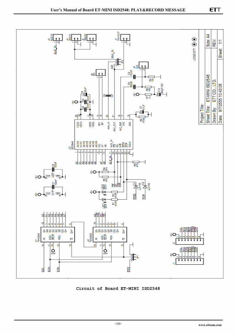
Circuit of Board ET-MINI ISD2548