user’s manual - novastar | global leading led display ... pluto control system use… ·...
TRANSCRIPT

User’s Manual Pluto Control System
Rev5.0.0 NS120100130
XI'AN N
OVASTAR TE
CH CO.,LTD.

User Manual of Pluto Control System
www.novastar.tech I
Statement
Dear users,
Welcome to use NovaPluto software. This manual is intended to help you to understand and use the product. For
accuracy and reliability, this manual may be revised or modified any time without notification. Any problems in
using this manual or any good suggestions, please contact us through ways provided in the manual. We will try
our best to solve the problems and evaluate and adopt the suggestions as soon as possible. Thank you very much!
Copyright
All the intellectual property rights of Easy Palette are owned by Xi’an NovaStar Tech Co., Ltd. (hereinafter referred
to as “NovaStar”). Easy Palette App and its related documents have registered copyrights. All rights are reserved to
NovaStar and protected by Copyright Law and Universal Copyright Convention.
Duplication of the software Easy Palette App, software dongle and relevant documents by any means without
written authority is a violation of the rights related to Easy Palette App owned by NovaStar.
Reverse engineering and system decryption of Easy Palette App are deemed as a server violation of NovaStar’s
rights.
Network attacks on Easy Palette App, regardless of business purpose or other purposes, is an intolerable violation
of NovaStar’s rights.
NovaStar shall condemn the violations of Easy Palette and reserve the right to take legal action against any
violation of Easy Palette.
Trademark
is the registered trademark of NovaStar.
XI'AN N
OVASTAR TE
CH CO.,LTD.

User Manual of Pluto Control System
www.novastar.tech II
Table of Contents
1 System Overview ................................................................................................................................................. 1
1.1 Configuration list .................................................................................................................................. 1
1.2 System structure .................................................................................................................................. 1
2 Operation Requirements ..................................................................................................................................... 2
3 Hardware Introduction and Connection .............................................................................................................. 3
4 Software Installation ............................................................................................................................................ 4
5 Network Deployment .......................................................................................................................................... 5
5.1 Hardware connection .......................................................................................................................... 5
5.2 System IP setting .................................................................................................................................. 5
6 Introduction to NovaLCT-Pluto .......................................................................................................................... 11
6.1 Main interface of NovaLCT-Pluto ....................................................................................................... 11
6.2 Menu/Toolbar .................................................................................................................................... 12
7 NovaLCT-Pluto Operations ................................................................................................................................. 14
7.1 LED display start ................................................................................................................................. 14
7.1.1 Start with system configuration file ........................................................................................... 14
7.1.2 Manual start ............................................................................................................................... 15
7.1.3 Set the cabinet information ....................................................................................................... 26
7.1.4 Adjust the performance parameters ......................................................................................... 27
7.1.5 Save settings to flash.................................................................................................................. 34
7.1.6 Save/Load configuration files ..................................................................................................... 34
7.2 Brightness adjustment, display quality, gamma and current gain ..................................................... 37
7.2.1 Manual adjustment .................................................................................................................... 38
7.2.2 Schedule adjustment ................................................................................................................. 40
7.2.3 Automatic adjustment ............................................................................................................... 41
7.3 Cabinet database ............................................................................................................................... 43
7.4 Display control ................................................................................................................................... 44
7.5 Monitor the system............................................................................................................................ 45
7.5.1 Monitor setting .......................................................................................................................... 46
7.5.2 Email notification setting ........................................................................................................... 47
7.5.3 Notification email Log ................................................................................................................ 48
7.5.4 Monitor-control ......................................................................................................................... 49
7.5.5 Monitor-control log.................................................................................................................... 51
7.6 Check the LED status .......................................................................................................................... 51
7.7 Brightness/Color calibration .............................................................................................................. 53
7.7.1 Online calibration ....................................................................................................................... 53
7.7.2 Coefficients management .......................................................................................................... 54
7.8 Function card management ............................................................................................................... 70
7.8.1 Power management ................................................................................................................... 70
7.8.2 Monitor data .............................................................................................................................. 72
7.8.3 External device management .................................................................................................... 72
7.8.4 Load program ............................................................................................................................. 73
7.9 Main board power management ....................................................................................................... 74
XI'AN N
OVASTAR TE
CH CO.,LTD.

User Manual of Pluto Control System
www.novastar.tech III
8 Introduction to PlutoManager ........................................................................................................................... 76
8.1 Software characteristics ..................................................................................................................... 76
8.2 PlutoManager interface ..................................................................................................................... 76
8.3 Menu/Toolbar .................................................................................................................................... 79
9 PlutoManager Operation Instruction................................................................................................................. 81
9.1 Client management ............................................................................................................................ 81
9.2 Create play-program .......................................................................................................................... 83
9.2.1 Play program structure .............................................................................................................. 85
9.2.2 Play program dispatch rule ........................................................................................................ 87
9.2.3 Display window setting .............................................................................................................. 89
9.2.4 Configure playlist directory ........................................................................................................ 91
9.2.5 Edit play program ....................................................................................................................... 92
9.3 Making sign list ................................................................................................................................ 101
9.3.1 Introduction to Toolbar ............................................................................................................ 102
9.3.2 Edit play list .............................................................................................................................. 103
9.3.3 Sending play list ....................................................................................................................... 108
9.4 Publish playList................................................................................................................................. 108
9.4.1 Online publish .......................................................................................................................... 108
9.4.2 Offline export ........................................................................................................................... 113
9.4.3 Publish temporary content ...................................................................................................... 114
9.4.4 Immediate notification ............................................................................................................ 116
9.5 Play management ............................................................................................................................ 118
9.5.1 Play control .............................................................................................................................. 118
9.5.2 Log management ..................................................................................................................... 120
9.5.3 Storage management ............................................................................................................... 121
9.6 Display control ................................................................................................................................. 121
9.6.1 Network configuration ............................................................................................................. 122
9.6.2 System configuration ............................................................................................................... 122
9.6.3 Server configuration ................................................................................................................ 127
9.6.4 Brightness adjustment ............................................................................................................. 128
9.6.5 Power schedule ........................................................................................................................ 133
9.7 Online upgrade ................................................................................................................................ 133
9.8 Time synchronization ....................................................................................................................... 134
9.9 Font management ............................................................................................................................ 135
9.10 Language management.................................................................................................................... 136
9.11 Display authorization ....................................................................................................................... 136
9.11.1 Authorization ........................................................................................................................... 136
9.11.2 Authorized decryption ............................................................................................................. 139
10 Hardware Program Upgrade .................................................................................................................... 141
11 Frequently Asked Questions .................................................................................................................... 142
12 Document Version Statement .................................................................................................................. 143
XI'AN N
OVASTAR TE
CH CO.,LTD.

User Manual of Pluto Control System
www.novastar.tech 1
1 System Overview
NovaPluto is a set of LED display centralized playback control program that can remotely release play programs,
monitor playback and screen body state, and remote control. This program has flexible network structure, so that
it can be easily deployed in the local area network and wide area network, supports the server-free, single-server,
and multi-server architectures, and suits different scale projects under different situations. The NovaCloud
software is required when a server is available. For details, see related materials about NovaCloud.
NovaPluto program mainly includes three parts which are the display configuration software NovaLCT-Pluto,
centralized playback control software (PlutoManager), and asynchronous controller PBOX100.
PluotManager is a play and management software for Pluto asynchronous control system, it can connect to the
asynchronous control card via LAN or internet. The main functions include client management, Play-Program
editing, Play-Program transmission, play status remote monitoring etc.
NovaLCT-Pluto software, referred to as LCT hereinafter, mainly controls the LED display’s smart setting,
performance parameter setting, brightness adjustment and calibration, to achieve the best performance of it.
1.1 Configuration list
Description Model/Version Function
A Controller PBOX100 Core control card
Configuration software
NovaLCT-Pluto
Parameters configuration, display calibration, and hardware
monitoring
PlutoManager Program publishing and play status monitoring
Accessories Accessories
1.2 System structure
Fig. 1-1 Architecture of server-free system
XI'AN N
OVASTAR TE
CH CO.,LTD.

User Manual of Pluto Control System
www.novastar.tech 2
2 Operation Requirements
In order to ensure the stability and security of the system operation, following requirements are recommended:
The computer of MC-go mainly runs management software, to achieve play program production, remote release,
remote monitoring and other functions.
Requirements for computer hardware configuration:
CPU: Dual-core, over 2.4GHz;
Hard disk drive:SCSI interface,with over 500GB capacity;
Video card:Independent video card, 3D hardware acceleration, over 1G video memory.
MC-go Computer software:
Operation system environment:windows XP SP3 and Windows7 32 bit;
Installation component:Microsoft .NET Framework; MC-go software NovaPluto.
XI'AN N
OVASTAR TE
CH CO.,LTD.
User Manual of Pluto Control System
www.novastar.tech 3
3 Hardware Introduction and Connection
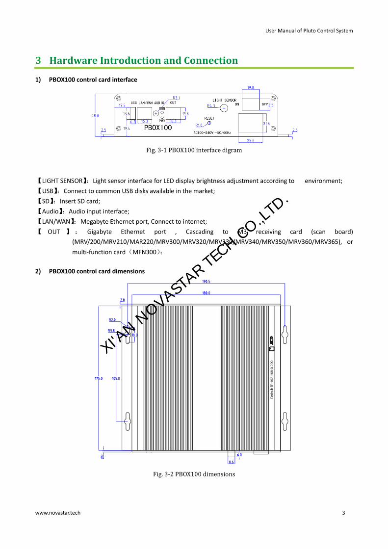
1) PBOX100 control card interface
Fig. 3-1 PBOX100 interface digram
【LIGHT SENSOR】:Light sensor interface for LED display brightness adjustment according to environment;
【USB】:Connect to common USB disks available in the market;
【SD】:Insert SD card;
【Audio】:Audio input interface;
【LAN/WAN】:Megabyte Ethernet port, Connect to internet;
【 OUT 】 : Gigabyte Ethernet port , Cascading to M3 receiving card (scan board)
(MRV/200/MRV210/MAR220/MRV300/MRV320/MRV330/MRV340/MRV350/MRV360/MRV365), or
multi-function card(MFN300);
2) PBOX100 control card dimensions
Fig. 3-2 PBOX100 dimensions
XI'AN N
OVASTAR TE
CH CO.,LTD.

User Manual of Pluto Control System
www.novastar.tech 4
4 Software Installation
Installation of NovaLCT-Pluto、PlutoManager is the same to other common software applications. Operate
according to the installation wizard.
Attention:
If notification of anti-virus software or firewall pops up, please allow it, because the installation process may
require to install serial port driver.
XI'AN N
OVASTAR TE
CH CO.,LTD.

User Manual of Pluto Control System
www.novastar.tech 5
5 Network Deployment
This section introduces several common network set-up solutions, so that users can deployment their network
according to their specific requirement and the local network environment. In order to ensure regular running of
the system, the operator is recommended to obtain some network knowledge before use.
5.1 Hardware connection
The Pluto system default IP is "192.168.0.220", before the network connection, set the network parameters of
each a synchronism card on the software NovaLCT-Pluto, it is recommended to adopt the direct network cable
connection to connect local computer and clients.
Fig. 5-1 Hardware Connection of NovaLCT-Pluto Configuration
Attention:
The local computer shall be directly connected to the 100Mpbs network port.
5.2 System IP setting
Run Nova LCT-Pluto on the local computer;
1) Click on System(S)→ Search All Display(S), LCT will search the Current Connected Pluto systems.
XI'AN N
OVASTAR TE
CH CO.,LTD.

User Manual of Pluto Control System
www.novastar.tech 6
Fig. 5-2 Search Pluto system window
Note: Click “Search Setting” to set search criteria, as shown in the following figure:
2) Click “Client”to check whether it is in the same network segment, and double click to modify the IP address; (Skip this step for the first direct-connection.)
Fig. 5-3 IP address modification
3) Click “Client”and then 【Connection System】;
XI'AN N
OVASTAR TE
CH CO.,LTD.

User Manual of Pluto Control System
www.novastar.tech 7
Fig. 5-4 System connection
Connection status is displayed on the operation interface after the connection is successful. Buttons on the LCT interface cannot be enabled until screen parameters rereading has been completed.
4) Click User (U)→Advanced login (A), to pop up the user login interface, and then enter the password
“admin”,click【Login】,to enter advanced user interface;
XI'AN N
OVASTAR TE
CH CO.,LTD.

User Manual of Pluto Control System
www.novastar.tech 8
Fig. 5-5 Advanced login
Fig. 5-6 Advanced interface
5) Click Setting (N)→Display Configuration (C)→Net Configuration (E),to enter the interface as follows:
Fig. 5-7 Network parameter settings
6) Tick 【Configure the asynchronous system information】, so that the user can modify the system name, and an easily recognizable system name will bring convenience to your later operation;
XI'AN N
OVASTAR TE
CH CO.,LTD.

User Manual of Pluto Control System
www.novastar.tech 9
Fig. 5-8 Setting system information
7) Tick the option 【Configure system network parameters to connect in the LAN】and 【Obtain an IP address
automatically】.
Fig. 5-9 Configure system network parameters to connect to LAN
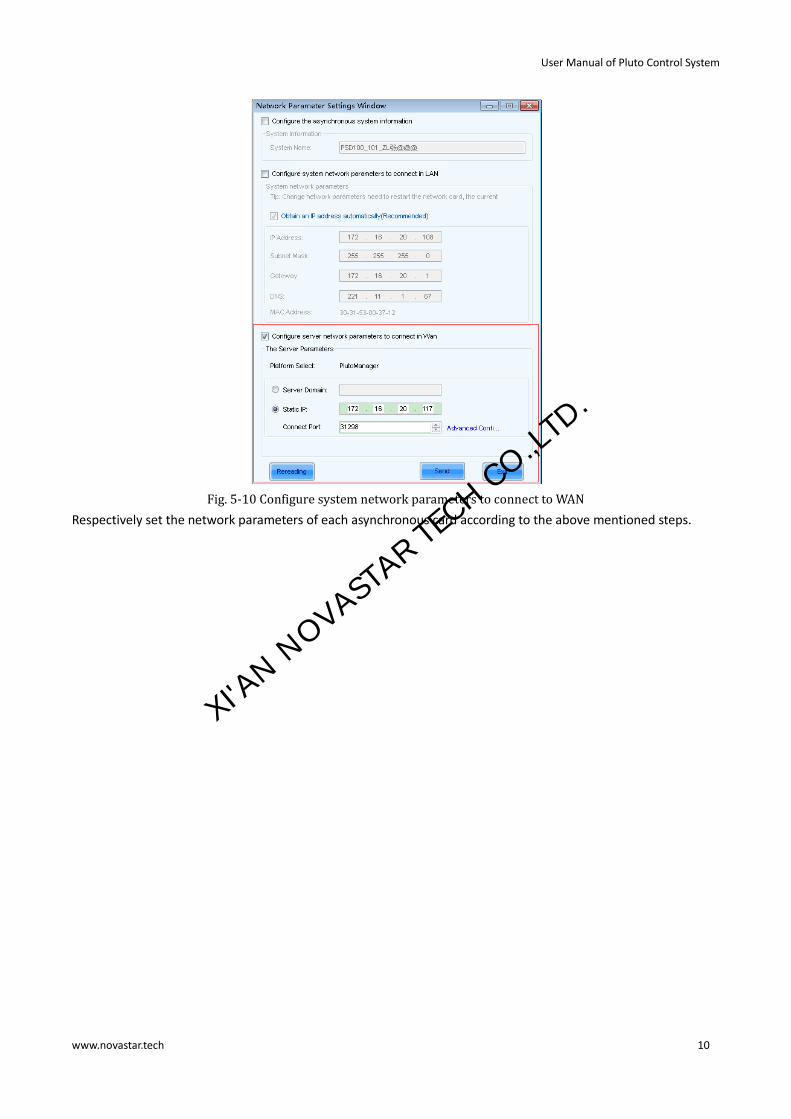
8) Tick 【Configure server network parameters to correct to Wan】, Set Server Domain, Static IP and Connect Port, and click Send.
XI'AN N
OVASTAR TE
CH CO.,LTD.
User Manual of Pluto Control System
www.novastar.tech 10
Fig. 5-10 Configure system network parameters to connect to WAN
Respectively set the network parameters of each asynchronous card according to the above mentioned steps.
XI'AN N
OVASTAR TE
CH CO.,LTD.

User Manual of Pluto Control System
www.novastar.tech 11
6 Introduction to NovaLCT-Pluto
NovaLCT ‐ Pluto software integrates functions of LED display configuration, brightness adjustment,
comprehensive working status monitoring, LED lights open/short circuit status checking and etc. NovaLCT-Pluto
also plays an important role in the pixel level LED display brightness/chromaticity calibration by working with
NovaCLB to fulfill the operation. With cabinet database and configuration files in use, it simplifies user’s operation.
6.1 Main interface of NovaLCT-Pluto
Fig. 6-1 Main interface of NovaLCT-Pluto
Title: Shows software name and version info;
Menu/Toolbar: See the next section for detailed description;
Remote System information: Shows related information of the currently connected clients;
Monitor information: Shows the overall monitoring results. Red point indicates error detected, and green
indicates no error. Click on the red point to access the alarm window which contains corresponding error info.
shown as below:
Fig. 6-2 Alarm window containing error info
XI'AN N
OVASTAR TE
CH CO.,LTD.

User Manual of Pluto Control System
www.novastar.tech 12
6.2 Menu/Toolbar
Table. 6-1 Description of Menu/Toolbar
Menu/Toolbar Function
System Search All Displays Search Pluto system through the network
Search Display by IP Search specific display by IP address
Settings
Software
Configuration
Set connection IP (current computer IP)
Set connection port (avoid port conflict with other
applications)
Display Configuration
Net
Configuration
View current IP of Pluto system, and configure
network parameters of it
Resolution
Configuration Readback、Configure current Resolution
Language
Configuration Readback、Configure current language
Display Authorized Encrypt the client, and generate the authorized file
Tools
Screen Configuration
Configure the display. (Accessible to advanced users
only)
Brightness
Adjust the brightness of LED display. Three modes
available: manually, scheduled and automatically.
Cabinet Database
Management
Manage existing cabinet database or create a new
one. (Accessible to advanced users only)
Calibration
Connect to NovaCLB software for display
calibration, including calibration coefficients
uploading and adjustment. (Accessible to advanced
users only)
Display Control
Show blank, lock an image, and continue the
playing
Monitor
Enter the monitoring page to access monitor
settings and results
Function Card
Enter the function card page to configure
Hardware Information View hardware info of currently connected control
system
Point Detect Enter point detect page to check LED open/short
XI'AN N
OVASTAR TE
CH CO.,LTD.

User Manual of Pluto Control System
www.novastar.tech 13
circuit status. (working only after LED display
configuration)
Color Restore Adjust color gamut
Main Board Power
Clocked, immediate off/on of terminal power
Plug-in Tool Test tool
Open Nova display test tools which contains all the
contents of LED display test
Calculator A shortcut to the calculator application of Windows
User Advanced User Login Password: admin
Language
Switch language
Help
User Documents User manual
About View the version of software, company name and
other info
Check for Updates Check for updates
XI'AN N
OVASTAR TE
CH CO.,LTD.

User Manual of Pluto Control System
www.novastar.tech 14
7 NovaLCT-Pluto Operations
7.1 LED display start
7.1.1 Start with system configuration file
The advantage of using system configuration file to configure LED display is that the configuration procedure is
very simple and easy, and no manual configuration operation is required.
Requirement: Configuration file of same type LED display exists.
Operating steps:
1) Click Screen Configuration button to open the window shown as below:
Fig. 7-1 Select screen configuration mode
Attention:
If the connected card is X6 series /X130/PBOX150/PSD80,there will not be Mode Select in the dialog box.
2) Click Load Configuration File, Click Browse to load the configuration file. 3) Click Next, and wait for the load finished.
Attention:
The loaded performance parameters from the configuration file can be adjusted if they are not suitable. Please
refer to 7.1.4 Adjust the performance for details about how to adjust the performance parameters.
XI'AN N
OVASTAR TE
CH CO.,LTD.

User Manual of Pluto Control System
www.novastar.tech 15
7.1.2 Manual start
7.1.2.1 Input Source Configuration (Only for X6 series/X130/PBOX150)
Click “Screen Configuration” in the main interface and select Screen Configuration to enter the “Send Card”
interface.
Choose between Manual Operation and Timing Operation to control the input source control, as shown below.
Fig. 7-2 Input source control
Manual Operation:
If the External Input Source is not checked, the asynchronous mode will be applied.
If the External Input Source is checked, the asynchronous mode will be applied as shown. The resolution of input
source can be set.
XI'AN N
OVASTAR TE
CH CO.,LTD.

User Manual of Pluto Control System
www.novastar.tech 16
Fig. 7-3 Set the resolution
The video source is an HDMI input source. Get the pictures from PC and Synchronous display.
Set the video mode of display:
Fixed Resolution: Users can choose one of the fixed values.
Customized Resolution: Users can set the value by themselves.
Attention: the interface is as follows when connecting PBOX150:
Now it supports the functions of full screen zooming and HDMI precedence:
Full screen zooming: after opening the function, the input source will be displayed in full screen zooming based on
the resolution of LED display; currently;
XI'AN N
OVASTAR TE
CH CO.,LTD.

User Manual of Pluto Control System
www.novastar.tech 17
HDMI precedence: after opening the function, it will switch to synchronous mode when HDMI reinsertion and
asynchronous card restart, i.e. precedence HDMI input source.
Timing operation:
Set the timing rule for automatically switching of input source based on time, as shown below.
Fig. 7-4 Timing operation
Click to add the concrete schemes of input source switching.
Fig. 7-5 Parameters of timing operation editing
Click OK after finishing the settings.
Attention: Timing operation is adjusted based on time, so the time of X65/X130 must be correct.
XI'AN N
OVASTAR TE
CH CO.,LTD.

User Manual of Pluto Control System
www.novastar.tech 18
7.1.2.2 Smart setting
Operating steps:
1) Select“Screen Configuration”option in the Fig.7-1, and click ”Next”, enter Scan Board window, as shown.
Fig. 7-6 Screen configuration page for manual configuration of LED display
2) Click“Smart Setting”button in“Scan Board”page and to open the Smart Setting dialog as shown below,
Fig. 7-7 Smart setting dialog
3) Select“Option 1: Smart setting”and click ”Next”to activate smart setting wizard. The Smart Setting Step 1 page will appear, as shown in Fig. 7-8,
XI'AN N
OVASTAR TE
CH CO.,LTD.

User Manual of Pluto Control System
www.novastar.tech 19
Fig. 7-8 Smart setting step 1
Data Type
the options have parallel drive, three-color 1-dot series, three-color 8-dot series, three-color 16-dot series,
four-color 1-dot series, four-color 8-dot series, and four-color 16-dot series.
Chip Type
Select the drive chip type from the list according to what is actually used for the cabinets, e.g. MBI5036, MBI5042
etc.
OE Polarity
This option can be High Effective, Low Effective or Unknown.
Module Tpe
The option can be regular module or irregular module. (Irregular module is not supported by this version)
Actual Pixel
This is the size of the real pixel array of a module. X represents the width and Y the height.
Decoding Type
The options can be Static, 74HC138 Code or Straight Decoding, choose according the type LED display module
actually used.
Scan Type
The options could be any scan rate between 1 scan and 1/16 scan or unknown.
Rows and columns of the Module in one scan board (also named receiving card)
This is the size of the module array in the cabinet which is being configured by smart setting.
Module Cascade Type
Select the corresponding option according to the module connection routing. Note that the cabinet should be
observed from the front when considering the cascading direction.
Attention:
A. If the module array size is set as the default (1 column, 1 row), the modules in the first rows of the module arrays of all cabinets will be lightened (LED lights on).
B. If the module array size is set as the real numbers, the last module of each first row of the module arrays of all cabinets will be lightened (LED lights on).
XI'AN N
OVASTAR TE
CH CO.,LTD.

User Manual of Pluto Control System
www.novastar.tech 20
4) Click“Next”in“Smart Setting Step 1”page to enter ”Smart Setting Step 2”page as shown. Select according to the module status,
Fig. 7-9 Smart setting step 2
Attention:
This step will be skipped if module OE polarity is known and set in Smart Setting Step 1.
5) Click“Next”in“Smart Setting Step 2”page to enter ”Smart Setting Step 3” page as shown,
Fig. 7-10 Smart setting step3
6) Click ”Next”in“Smart Setting Step 3”page after selection to enter ”Smart Setting Step 4”page as shown, and enter the number of LED rows that are lightened in a module.
Fig. 7-11 Smart setting step 4
7) Click“Next”in ”Smart Setting Step 4” page to enter “Smart Setting Step 5”page as shown, Enter the number of LED columns that are lightened in a module.
Fig. 7-12 Smart setting step 5
8) Click“Next”in ”Smart Setting Step 5" to enter “Smart Setting Step 9”page as shown, Click the corresponding grids according to the position of the lightened LEDs until no LED is lightened any more. A line of the lightened LEDs routing will be drawn at the same time. A message indicating the finish of the Smart Setting
XI'AN N
OVASTAR TE
CH CO.,LTD.

User Manual of Pluto Control System
www.novastar.tech 21
Step 9 will be shown when enough LEDs have been processed.
Fig. 7-13 Smart setting step 9
Attention:
Press left button and drag the mouse to accomplish quick routing drawing.
Use“Automatic”button to accomplish drawing routing lines of the same pattern.
9) Click“Next”In“Smart Setting Step 9”page to open “Save Module” dialog which is for saving the settings set
for the module through all the smart setting steps. The “Save Module dialog” is shown below. Saving the module settings to files (module configuration files or cabinet database files) will make it easier to perform module configuration for another LED displays constructed by modules which require the same settings as the one just set (Choose Option 2 or 3 in "Smart Setting dialog" in Step 2), select corresponding files and modules and smart setting is done.) Click “Finish” to finish smart setting after saving the settings. Click“Finish”directly if you don’t want to save the settings.
Fig. 7-14 Save module dialog
Attention:
The saved module settings can be used in Fig. 7-4 by choosing option 2 or 3 to simplify smart setting process.
7.1.2.3 LED Display Configuration
According to the quantity of scan board, there’re two different modes for LED display configuration: No scan
board cascaded mode or cascading scan board mode.
1) No scan board cascaded mode (one PSD100 Asynchronous card only)
Switch to “Screen Config” page in Fig. 7-1, interface of No scan board cascaded mode as shown below:
XI'AN N
OVASTAR TE
CH CO.,LTD.

User Manual of Pluto Control System
www.novastar.tech 22
Fig. 7-15 Screen configuration in no scan board cascaded mode
Read form hardware
This is used for the application to read the LED display configuration information from the hardware.
2) Cascading scan board mode (PSD100 Asynchronous card cascading MRV300/MRV320 scan board)
The mode of cascade receiving card is divided into sending card mode and multi-display configuration. The
former is asynchronous card without box carrier, equal to sending card. Multi-display configuration is usually used
for dual panels. Both panels play the same picture. Multi-display mode does not support correction.
There are three LED display types, which are simple screen, standard screen and complex screen. These options
will be shown at the top of each screen page in the Screen Configuration page. Choose a screen type before any
configuration operation. Configurations for different type of screen will be given respectively as follows.
a) Simple screen configuration
Simple screen means each scan board drives same pixel array, edit items below according to LED display status.
XI'AN N
OVASTAR TE
CH CO.,LTD.

User Manual of Pluto Control System
www.novastar.tech 23
Fig. 7-16 Simple screen configuration page
Sender Mode
If asynchronous card carries no box carrier, please tick this item;
Location
This is the upper-left corner of a rectangular area of the computer display. The rectangle area of the computer
display is called mapping area. Content inside the mapping area will be shown on the LED display. The default
location is (0,0), which is actually the upper-left corner of the computer display.
Virtual Mode
Specify the pixel mode of the LED display. The option could be real pixel or virtual 3 LEDs or virtual 4 LEDs.
Scan Board Columns/Rows
These are the quantity of columns and rows of the scan boards (receiving cards) array of the LED display.
Scan Board Width/Height
These two parameters in the Scan Board Info panel refer to the width and height of the pixel array driven by a scan
board (receiving card). They must be set the same as those set in the Scan Board page.
Open File
This is used for the application to load the LED display configuration settings from a file.
Save File
This is used to save the LED display configuration settings to a .scr file.
Send to Screen
This is used to send the LED display configuration settings to the connected PSD100 Asynchronous card.
Save to Screen
This is used to save the settings to a FLASH chip. The saved data won’t be lost even the hardware is powered off.
b) Standard screen configuration
Configure scan boards connection routing manually, and each scan board could drive different pixel array.
XI'AN N
OVASTAR TE
CH CO.,LTD.

User Manual of Pluto Control System
www.novastar.tech 24
Fig. 7-17 Standard screen configuration page
【Location】
This is the upper-left corner of a rectangular area of the computer display.
The rectangle area of the computer display is called mapping area. Content
inside the mapping area will be shown on the LED display. The default
location is (0,0), which is actually the upper-left corner of the computer
display.
【Virtual Mode】 Specify the pixel type of the LED display. The option could be real pixel or
virtual 3 LEDs or virtual 4 LEDs.
【Scan Board】
【Columns/Rows】
These are the quantity of columns and rows of the scan board (receiving
card) array of the LED display. A sketch map of the scan board array as
Fig.8-13 will be shown in this page after these two parameters are set.
【Reset All】 This button is used to reset all cabinet settings and connection settings.
【Clear Port】 This button is used to clear all settings related to the current Ethernet port.
【Width】 It is the width of the pixel array drove by the sending card.
【Height】 It is the height of the pixel array drove by the sending card.
【Apply to Port】 Click this button to set the pixel array sizes of all scan boards connected to
the current Ethernet port the same as that of the current scan board.
【Set Blank】 Select this if the current position (pixel array of the current scan board) needs
to be left unset.
【Set Relay】 The current scan board ‘size is “0”.
Standard screen configuration method:
The configuration operation is easy. First, set the index as 1 for the receiving card (scan board) directly connected
to the asynchronous card through an Ethernet port and input values for other parameters. And then set the index
XI'AN N
OVASTAR TE
CH CO.,LTD.

User Manual of Pluto Control System
www.novastar.tech 25
as 2 for the receiving card which is connected to the first (index 1) receiving card and also input values for other
parameter for the No.2 receiving card. Do the same configuration operation until all receiving cards are set. The
configuration is completed by then. The pixel array sizes of the receiving cards can be different from each other,
and can also be left unset. After configuration, click corresponding button to send the configuration information to
the receiving card or save it in the computer.
Attention:
X130 supports two output ports, so there are two ports when it is used, as shown below.
c) Complex screen configuration
Need to configure each scan board’s starting Coordinates and pixel array respectively.
Fig. 7-18 Complex screen configuration page
XI'AN N
OVASTAR TE
CH CO.,LTD.

User Manual of Pluto Control System
www.novastar.tech 26
Add
Click Add to access the page for scan boards information setting, such as Ethernet output ports, mapping areas,
pixel array sizes and so on. The setting will be shown in the list.
Edit
To edit the information that has been set for scan boards.
Delete
To delete the selected scan board from the scan boards list.
Clear
To delete all scan boards from the list.
7.1.3 Set the cabinet information
Switch to Scan Board page,
Fig. 7-19 Set the cabinet info
Cabinet information
Pixel array size and module cascade direction can be set in this panel. Note that the Regular panel is for regular
shape cabinet parameters setting and the Irregular panel is for irregular shape cabinet parameters setting.
(Irregular shape cabinet is not supported by this version) Shown in Fig. 7-20 is the Regular Cabinet Info panel
which is circled and marked as area 1 in Fig. 7-19.
Fig. 7-20 The regular cabinet info panel
XI'AN N
OVASTAR TE
CH CO.,LTD.

User Manual of Pluto Control System
www.novastar.tech 27
Width/Height
These two items specify the width and height of the cabinet pixel array. Note that the two numbers circled are the
maximum values that can be set, which is also named as Maximum Width and Maximum Height.
Maximum Width
Maximum width varies with parameters of refresh rate, gray scale levels, and shift clock frequency. Normally, the
higher the refresh rate is and the higher the gray scale levels are, the smaller the maximum width will be; while
the higher the shift clock frequency is, the larger the maximum width can be. But as the shift clock frequency is
limited by drive chips and module design, the maximum width is also limited.
Maximum Height
The Maximum Height depends on the module design.
Attention:
A. If the module cascade direction is from left to right or from right to left, then as mentioned above, the Maximum Width depends on the parameters such as refresh rate, gray scale levels and shift clock frequency, and the Maximum Height depends on the module design.
B. If the module cascade direction is from top to bottom or from bottom to top, then, factors affect the Maximum Width and Height are just switched. The Maximum Height depends on the parameters such as refresh rate, gray scale levels and shift clock frequency, and the Maximum Width depends on the module design.
7.1.4 Adjust the performance parameters
To achieve the best performance, performance parameters should be set properly. Performance parameters
setting can be through the performance setting panel which is circled and marked as area 2 in Fig. 7-19.
Fig. 7-21 Performance setting panel
Data groups exchange: adjusts the order of data groups;
More settings:
1) Symmetrical/Data Group Extension
XI'AN N
OVASTAR TE
CH CO.,LTD.
User Manual of Pluto Control System
www.novastar.tech 28
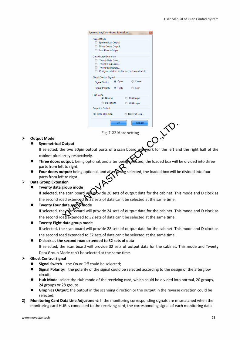
Fig. 7-22 More setting
Output Mode Symmetrical Output
If selected, the two 50pin output ports of a scan board will work for the left and the right half of the
cabinet pixel array respectively.
Three doors output: being optional, and after being selected, the loaded box will be divided into three parts from left to right.
Four doors output: being optional, and after being selected, the loaded box will be divided into four parts from left to right.
Data Group Extension Twenty data group mode
If selected, the scan board will provide 20 sets of output data for the cabinet. This mode and D clock as
the second road extended to 32 sets of data can't be selected at the same time.
Twenty Four data group mode
If selected, the scan board will provide 24 sets of output data for the cabinet. This mode and D clock as
the second road extended to 32 sets of data can't be selected at the same time.
Twenty Eight data group mode
If selected, the scan board will provide 28 sets of output data for the cabinet. This mode and D clock as
the second road extended to 32 sets of data can't be selected at the same time.
D clock as the second road extended to 32 sets of data
If selected, the scan board will provide 32 sets of output data for the cabinet. This mode and Twenty
Data Group Mode can't be selected at the same time.
Ghost Control Signal
Signal Switch:the On or Off could be selected;
Signal Polarity:the polarity of the signal could be selected according to the design of the afterglow circuit;
Hub Mode: select the Hub mode of the receiving card, which could be divided into normal, 20 groups, 24 groups or 28 groups.
Graphics Output: the output in the scanning direction or the output in the reverse direction could be selected.
2) Monitoring Card Data Line Adjustment: If the monitoring corresponding signals are mismatched when the monitoring card HUB is connected to the receiving card, the corresponding signal of each monitoring data
XI'AN N
OVASTAR TE
CH CO.,LTD.

User Manual of Pluto Control System
www.novastar.tech 29
line can be adjusted manually.
Fig. 7-23 Monitoring card data line adjustment
3) Additional Function:eliminate the afterglow of the insolated points, and shut down the indicators of the receiving card, Shorten the synchronization time, Brightness slowly brighten, and EMC Function.
Fig. 7-24 Additional Function
4) Flash Arrangement
Fig.7-25 is the physical connection schematic diagram of Flash. According to that diagram, the sequence number
of BUS is determinedly selector. Users shall consult HUB board designer for connection of the flash module to
confirm the sequence number of BUS. One BUS can be cascaded with multiple modules. The MOM Topology can
be set on the software according to the actual order of connection.
XI'AN N
OVASTAR TE
CH CO.,LTD.

User Manual of Pluto Control System
www.novastar.tech 30
Fig. 7-25 Physical connection schematic diagram of flash
As shown in Fig. 7-26, to set MOM Topology on the software, firstly set FLASH row and column numbers,and then
click anywhere on the right side of the window, select the corresponding BUS, and based on the actual route, click
the left button of the mouse or press the arrow key to set each piece of Flash information according to the order
(control size and coordinates).
Select a BUS and set Flash control size, and then click "Apply to current BUS"; the size of Flash with BUS
connection will be modified as the current value.
After Flash Control Size is set, click “Reset All”, and then all Flash Control Sizes will be reset as the size set
currently.
XI'AN N
OVASTAR TE
CH CO.,LTD.

User Manual of Pluto Control System
www.novastar.tech 31
Fig. 7-26 MOM pysical setting
Refresh Rate
This is the rate that images shown on a LED display are update. The higher the refresh rate is, the more stable the
video is for watching.
Gray Scale
Normally, 256 levels of gray scale is enough for two-color LED displays, 4096 levels enough for indoor full color LED
displays, and 16384 levels enough for outdoor full color LED displays. And apparently, the more levels the gray
scale is divided into, the more exquisite the shown images will be.
Gray Mode
There are four options for Gray Mode, Brightness First, Refresh Rate First, Gray Firsthand Performance balance.
Brightness First: Brightness First mode is for normal use and it has lower brightness loss.
Refresh Rate First: image refresh rate can be greatly increased, but the cost is 8% of brightness loss.
Gray First: Gray First mode will cost 50% brightness to get a better gray when display with low bright. Performance balance: Balance between gray scale and refreshing, and promote refresh rate of low gray level. Accelerate Rate
This parameter is used to increase the refresh rate. If N is selected, the refresh rate will be increased by N
times.
Data Clock
This is the shift clock frequency. The shift clock frequency depends on the performance of driver chips and the
circuit design of the modules. The higher the driver chip performance is and the better the module circuit is
designed, the higher the shift clock frequency can be. A higher shift clock frequency will results in a larger pixel
array, more gray levels or higher refresh rate that a receiver card can support.
XI'AN N
OVASTAR TE
CH CO.,LTD.

User Manual of Pluto Control System
www.novastar.tech 32
Data Duty
This is the duty cycle for the shift clock. The shift clock frequency can be increased by changing this parameter.
Normally, the duty cycle should be set as 50%.
Data Phase
By phase here refers to the time relation between the shift clock and the corresponding data to be shifted. This
parameter can be used to eliminate the errors due to the phase, such as image dislocation and flashing pixels.
Low Gray Compensation
For driver chips that cannot respond to narrow pulse signals, the Low Gray Compensation
parameter can be used to improve the image quality of low gray levels.
Blanking Time
This is the line blanking interval. This parameter can be used to weaken the decoy. Increase the value of this
parameter if decoy is serious.
Ghost Control
This refers to the time to end the process for weakening decoy. It is used in conjunction with Blanking Time and
Line Change Time to weaken the decoy.
Line Change Time
This parameter refers to the time to switch to the next row. It is used in conjunction with Blanking Time to weaken
the decoy of scan mode LED displays.
The steps of performance parameters adjustment are as follow.
Step 1
Adjust the parameters in the Performance Setting panel (Fig.7-21) until the Maximum Width and Height shown in
the Cabinet Info panel (Fig.7-20) are larger than the pixel array size of the cabinet. Then click the Send To HW
button on Fig.7-19.
Attention:
If the message as follow appears after clicking the Send To HW button, it means there are parameters not properly
set in the Performance Setting panel or the Cabinet Info panel. Those parameters will be in red. Reset those
parameters and click Send To HW button again.
Step 2
If all parameter settings are acceptable, the dialog as shown in Fig.7-27 will appear after clicking the Send To HW
button.
Fig. 7-27 The dialog for specifying receiver cards to send the parameter settings to
XI'AN N
OVASTAR TE
CH CO.,LTD.

User Manual of Pluto Control System
www.novastar.tech 33
All Scan Boards
When this option is selected, parameter settings will be sent to all receiver cards (scan boards) that are connected
to the current serial port through the sending boards that are connected with the current serial port.
Reset the start position of scan boards
This option is available when All Scan Boards is selected. When this option is checked, start positions of all relating
receiver cards (receiver cards that are connected to the current serial port through the sending boards that are
connected with the current serial port.) will be set as (0,0). Thus all relating receiver cards will show (on their pixel
arrays) the upper left corner image of the computer display.
Specified Scan Boards
This option is for sending parameter settings to specific receiver cards. There are two ways for sending parameter
settings to specific receiver cards,by address and by sketch map. Corresponding pages are shown in Fig.7-28 and
Fig.7-29.
Fig. 7-28 The send by address page
Shown in Fig.7-28 is the Send by Address page. The Sending#, Port and Scan Bo are used to specify the receiver
cards to which the settings will be sent. Set these three parameters according to the instructions given at the
lower half of the page.
XI'AN N
OVASTAR TE
CH CO.,LTD.

User Manual of Pluto Control System
www.novastar.tech 34
Fig. 7-29 The send by topology page
Shown in Fig.7-29 is the Send by Topology page. The sketch of the receiver cards layout is show in this page. Select
the receive cards from the sketch. To select multiple scan boards, press the left button and drag the mouse.
Step 3
Click Send button and the parameter settings will be sent all or the specified receiver cards.
7.1.5 Save settings to flash
Once data is saved in the FLASH chips of the hardware, the saved data won’t be lost even the hardware is powered
off. To save the settings to FLASH, click the in the Screen Config page (Fig. 7-19).
Attention:
Please save the settings to FLASH (click the Save to Screen button) after sending settings of the LED display
configuration, performance parameters and hot backup to hardware.
7.1.6 Save/Load configuration files
There are four types of configuration files at present, the module configuration file, the scan board configuration
file, the LED display configuration file and the system configuration file.
Module Configuration File
Saved in a module configuration file are the settings of modules. Module configuration files can be used for quick
configuration of modules requiring the same kind of settings.
Scan board Configuration File
Saved in a scan board configuration file are the settings of scan boards. Scan board configuration files can be used
for quick configuration of cabinets requiring the same kind of settings.
LED Display Configuration File
Saved in a LED display configuration file are the information of how scan boards are put together to construct a
XI'AN N
OVASTAR TE
CH CO.,LTD.

User Manual of Pluto Control System
www.novastar.tech 35
LED display. The LED display configuration files can be used for quick construction of a LED display.
System Configuration File
Saved is a system configuration file is the complete setting information of a LED display control system. It can be
used to quickly recover a LED display control system from error, or to quickly start a LED display.
1) Save a module configuration file
There are two ways to save a module configuration file.
The first is to save it at the last step of smart setting (please refer to 0
Smart setting -> 9) for details). Shown is the dialog for saving module settings to a module configuration file.
Fig. 7-30 Dialog for saving module settings to module configuration file
The other way is to click button in the Module Info panel of the Scan Board page. The module settings can
be saved to a module configuration file through the opened dialog. Shown in Fig. 7-31 is Module Info panel of the
Scan Board page that the button is on.
Fig. 7-31 Module info panel
2) Load a module configuration file
In smart setting step 2 (Please refer to 0
Smart setting -> 2), select Option 2: Load module from file in the Smart Setting dialog and follow the instructions.
3) Save a scan board configuration file
To save settings to a scan board configuration file, click at the bottom of the Scan Board page in
the Screen Config window and follow the instructions. Shown in Fig. 7-32 is the Scan Board page.
XI'AN N
OVASTAR TE
CH CO.,LTD.

User Manual of Pluto Control System
www.novastar.tech 36
Fig. 7-32 Scan Board page
4) Load a scan board configuration file
To load a scan board configuration file, click at the bottom of the Scan Board page in the Screen
Config window and follow the instructions.
5) Save a LED display configuration file
To save settings to a LED display configuration file, click at the bottom of the Screen Config page of
the Screen Config window and follow the instructions. Shown in Fig. 7-33is the Screen Config page.
Fig. 7-33 Screen config page
XI'AN N
OVASTAR TE
CH CO.,LTD.

User Manual of Pluto Control System
www.novastar.tech 37
6) Load a LED display configuration file
To load a LED display configuration file, click at the bottom of the Screen Config page in the Screen
Config window and follow the instructions.
7) Save a system configuration file
To save settings to a system configuration file, click at the bottom of the Screen Config window
and follow the instructions.
Fig. 7-34 Screen config window
8) Load a system configuration file
Please refer to 7.1.1 Start with System Configuration Files for details.
7.2 Brightness adjustment, display quality, gamma and current
gain
Click Brightness button from the toolbar or select Tools->Brightness from the main menu of the NovaLCT-Pluto
application main interface to open the Display Adjustment page for brightness, display quality, Gamma and
current gain adjustment. Shown in Fig. 7-35 is the Display Adjustment page.
XI'AN N
OVASTAR TE
CH CO.,LTD.

User Manual of Pluto Control System
www.novastar.tech 38
7.2.1 Manual adjustment
Fig. 7-35 Manual adjustment page of display adjustment
Display Quality
There are two modes for display quality, soft mode and Enhanced Mode, Use soft mode for the situation that the
environment brightness is not very high. Enhanced Mode is better when the background is very bright.
Gamma Adjustment
If Fixed Value is selected, the Gamma coefficient can be any value between 1 and 4. And the default value is 2.8.
Select Custom to manually define the Gamma table.
Brightness Adjustment
Brightness can be adjusted by the slide bar. All together there are 256 levels of brightness.
Color Temperature Adjustment
Color temperature adjustment can be done in two ways, customization and color temperature table. Choose one
as you want. Select Custom and the color temperature can be adjusted through the brightness and current gains
of Red, Green and Blue components. Click Color Temperature button to open the dialog for color temperature
table configuration. Color temperature can be adjusted by changing the items in the table.
Attention:
A. Current gain adjustment option won’t be available if the LED drive chips do not support current gain adjustment.
B. Professional equipment is necessary to find out the current gains and brightness of red, green and blue for different LED display brightness of certain color temperature, so that if the color temperature table has been
XI'AN N
OVASTAR TE
CH CO.,LTD.

User Manual of Pluto Control System
www.novastar.tech 39
set, NovaLCT-Pluto will adjust the LED display settings according to the current brightness setting and keep the color temperature unchanged.
Configure the Color Temperature Table
Fig. 7-36 Color temperature table configuration page
XI'AN N
OVASTAR TE
CH CO.,LTD.

User Manual of Pluto Control System
www.novastar.tech 40
7.2.2 Schedule adjustment
Fig. 7-37 Schedule adjustment
Fig. 7-38 Adding information about the schedule adjustment
Select Schedule in the Display Adjustment page to open schedule adjustment page. Schedule adjustment is to
generate a time table and the LED display brightness, Gamma, color temperature will be adjusted according to the
time table.
Attention:
The time of the computer on which NovaLCT-Pluto is running is the base of the schedule. If the computer time is
not correct, the adjustment operation will not be performed at the expected time.
XI'AN N
OVASTAR TE
CH CO.,LTD.

User Manual of Pluto Control System
www.novastar.tech 41
7.2.3 Automatic adjustment
Select Schedule in the “Adjustment Mode” panel to open auto adjustment page. Then click Config button.
Fig. 7-39 Auto adjustment page
Fig. 7-40 Auto Adjustment settings
The LED display control system uses light sensors to get the environment brightness.
XI'AN N
OVASTAR TE
CH CO.,LTD.

User Manual of Pluto Control System
www.novastar.tech 42
Add light sensor
Click button in Fig. 7-40 and NovaLCT-Pluto will automatically detect light sensors that are connected to
asynchronous cards and add them to the lightness sensor list, as shown in the following figure.
Fig. 7-41 Light sensor list page
The retry number when adjustment failed
If NovaLCT-Pluto fails in auto brightness adjustment, it will retry the adjustment again. The number set here is
times NovaLCT-Pluto try to adjust the brightness before it give up.
Detect Period
The time period the light sensors measure the environment brightness.
Read times of light sensors
The times that NovaLCT-Mars reads the measurement results of the light sensors.
Auto brightness timeinterval
The auto brightness time interval is the production of Detect Period and Read times of light sensors.
For example, if light sensors measure the environment brightness every 10 second (this is the Detect Period.) and
NovaLCT-Mars reads the measurement results of the light sensors for 5 times (this is the Read times of light
sensor.) before adjusting the LED display brightness, the auto brightness time interval will be 50 seconds.
Calculate Type of Lux
This is to specify how the final result is calculated from the measurement results of all light sensors.
Fix Color Temperature
If this option is selected, the LED display brightness will be adjusted according to the color temperature table and
the environment brightness.
Number of Segments
Thresholds need to be set for automatic brightness adjustment. When the environment brightness is higher than
the high side threshold, a high brightness level will be set for the screen, for example 100%. And while the
environment brightness is lower than the low side threshold, a low brightness level is set. The interval between
the high and low threshold of environment brightness is linearly divided into subsections with subsection number
equals the Number of Segments. So does the interval between the high and low LED display brightness levels. If
the environment brightness is in certain subsection, the corresponding brightness level will be set for the LED
display. The maximum number is 10.
XI'AN N
OVASTAR TE
CH CO.,LTD.
User Manual of Pluto Control System
www.novastar.tech 43
Attention:
A. The information of the multifunction card light sensor list is from the multifunction card configuration settings.
B. NovaLCT-Pluto first generates the environment brightness value from measurement results of all available light sensors according to certain calculating algorithm. And then NovaLCT-Pluto uses the generated environment brightness to adjust the LED display brightness according to the parameter settings, such as brightness thresholds, segment numbers.
7.3 Cabinet database
This is to manage the existing cabinet libraries or creating new cabinet libraries. It helps in quick configuration of
the cabinets and modules.
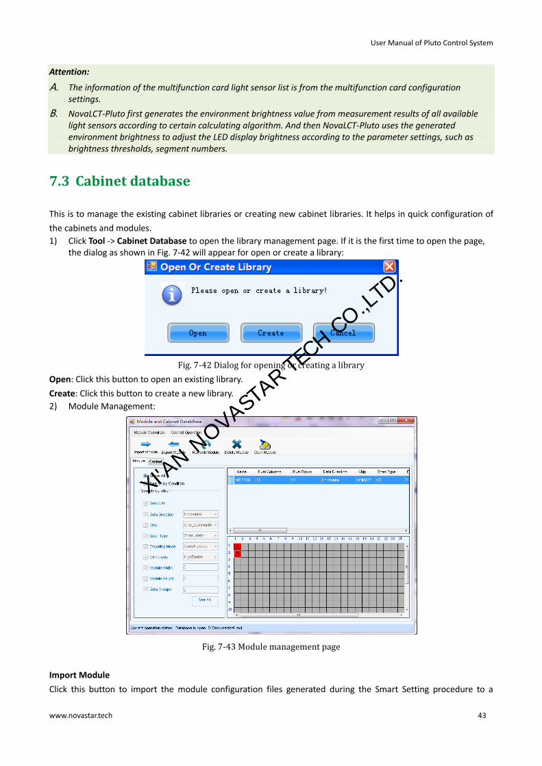
1) Click Tool -> Cabinet Database to open the library management page. If it is the first time to open the page, the dialog as shown in Fig. 7-42 will appear for open or create a library:
Fig. 7-42 Dialog for opening or creating a library
Open: Click this button to open an existing library.
Create: Click this button to create a new library.
2) Module Management:
Fig. 7-43 Module management page
Import Module
Click this button to import the module configuration files generated during the Smart Setting procedure to a
XI'AN N
OVASTAR TE
CH CO.,LTD.

User Manual of Pluto Control System
www.novastar.tech 44
cabinet library.
Export Module
Click this button to export the module configurations from a cabinet library to a module configuration file. Module
configuration files help in speeding up the Smart Setting procedure.
Show All
Select this option to request NovaLCT-Pluto to show module configurations of all cabinets in the list.
Search by Condition
Select this option to shown all module configurations that meet the requirements set in the Search Condition
panel in the list.
3) Cabinet Management:
Fig. 7-44 Cabinet management page
Import Cabinet
Click this button to import a cabinet configuration file to a cabinet library.
Export Cabinet
Click this button to export the cabinet configurations from a cabinet library to a cabinet configuration file.
Show All
Select this option to shown in the list all cabinets’ configurations in the library.
Search by Condition
Select this option to shown the configurations of the cabinets that meet the requirements set in the Search
Condition panel in the list.
7.4 Display control
Click Display Control button from the toolbar or select Tools->Display Control from the main menu of the
NovaLCT-Pluto application main interface to open the Screen Control page as shown below in Fig. 7-45:
XI'AN N
OVASTAR TE
CH CO.,LTD.

User Manual of Pluto Control System
www.novastar.tech 45
Fig. 7-45 Screen control page
Kill: Show nothing on the LED display.
Lock: Always show the current image frame of the LED display.
Run: Switch the LED display back to normal from Kill or Lock.
7.5 Monitor the system
Monitoring is one of the key features of the Mars serial LED display control systems. The monitoring subsystem
performs comprehensive monitoring on the overall LED display. The monitored parameters and status include
system components working status, cabinet door status (open/close) and temperature, humidity, smoke, fans
status and power supply. The monitoring subsystem can also report error by email when fails detected.
Shown below is the Monitor page. The status and parameters mentioned above can all be viewed here.
Fig. 7-46 Monitor page
Refresh
This button is used to update the monitored data.
Monitor Setting
This button is used to edit the contents to be monitored and set rules for alarm.
Email Setting
This button is used to set the email notification.
XI'AN N
OVASTAR TE
CH CO.,LTD.
User Manual of Pluto Control System
www.novastar.tech 46
Email Log
Click this button to check the log of the report email sent by NovaLCT-Pluto monitoring subsystem.
Monitor-Control
Configure the temperature and smoke monitoring control program.
Control log
Check control scheme acting result.
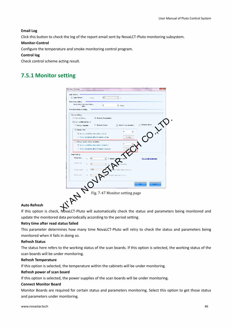
7.5.1 Monitor setting
Fig. 7-47 Monitor setting page
Auto Refresh
If this option is check, NovaLCT-Pluto will automatically check the status and parameters being monitored and
update the monitored data periodically according to the period setting.
Retry time after read status failed
This parameter determines how many time NovaLCT-Pluto will retry to check the status and parameters being
monitored when it fails in doing so.
Refresh Status
The status here refers to the working status of the scan boards. If this option is selected, the working status of the
scan boards will be under monitoring.
Refresh Temperature
If this option is selected, the temperature within the cabinets will be under monitoring.
Refresh power of scan board
If this option is selected, the power supplies of the scan boards will be under monitoring.
Connect Monitor Board
Monitor Boards are required for certain status and parameters monitoring. Select this option to get those status
and parameters under monitoring.
XI'AN N
OVASTAR TE
CH CO.,LTD.

User Manual of Pluto Control System
www.novastar.tech 47
Refresh Humidity
If this option is selected, the humidity within the cabinets will be under monitoring.
Refresh Smoke
If this option is selected, the smoke within the cabinets will be under monitoring.
Refresh cabinet status
If this option is selected, the working status of the cabinets will be under monitoring.
Refresh status of Cabinet-Door
If this option is selected, the open/close status of the cabinet doors will be under monitoring.
Refresh Fan
If this option is selected, the fans status will be under monitoring.
Every cabinet has same number of fan
If for every cabinet, the number of fans to be monitored is the same, select this option and set the fan number in
the box to the right of this option.
Ever cabinet has different number of fan
If the numbers of fans to be monitored are different from one cabinet to another, select this option and click the
Setting button to set the fan numbers for each cabinet.
Refresh power of monitor board
If this option is selected, the power supplies on the monitor board will be under monitoring.
Every cabinet has same number of power
If for every monitor board, the number of power supplies to be monitored is the same, select this option and set
the power supplies number in the box to the right of this option.
Every cabinet has different number of power
If the numbers of power supplies to be monitored are different from one monitor board to another, select this
option and click the Setting button to set the power supplies numbers for each cabinet.
7.5.2 Email notification setting
Operation steps:
1) Click Email Settings button in the Monitor Page of Fig. 7-48 to enter the email notification setting page shown as below: XI'A
N NOVAST
AR TECH CO.,LT
D.

User Manual of Pluto Control System
www.novastar.tech 48
Fig. 7-48 Email notification setting page
2) To enable email notification, email sender, recipient and email info need to be set, click Apply button after setting.
7.5.3 Notification email Log
If email notification is enabled in the email notification setting page of Fig. 7-48, user can view notification email
log by clicking Email log in the Monitor Page of Fig. 7-49 as show below:
User can search notification email log by date or delete overdue logs manually.
Fig. 7-49 History of notification emails
XI'AN N
OVASTAR TE
CH CO.,LTD.

User Manual of Pluto Control System
www.novastar.tech 49
7.5.4 Monitor-control
7.5.4.1 Configure control scheme
Fig. 7-50 Configuration of monitor-control
Enable Monitor-Control
The functions of Monitor-Control will work only when the option is checked.
Valid days of logs
Set the valid days of logs.
One control information can be added by clicking the button in Fig.7-50. As it show in Fig. 7-51 is to
add one temperature control information, as it show in Fig. 7-52 is to add one smoke control information.
Fig. 7-51 Temperature control information
XI'AN N
OVASTAR TE
CH CO.,LTD.

User Manual of Pluto Control System
www.novastar.tech 50
Fig. 7-52 Smoke control information
Fig. 7-53 Select the controlled power
7.5.4.2 Recovering of monitor-control
The latest control information will show in the bottom right corner in the main form and the monitor page. As it
show in Fig. 7-54 is the information which comes from the last control.
Fig. 7-54 Control information in the monitor page
Click this link label to view the controlled information list as it show in Fig.7-55.
XI'AN N
OVASTAR TE
CH CO.,LTD.

User Manual of Pluto Control System
www.novastar.tech 51
Fig. 7-55 View the control information list
Recover Control
If the control scheme is performed(View 7.5.4.1 Configure Control Scheme to configure the control scheme), and
the user can restart monitor-control by clicking this button after dealing with the fault.
View Log
Open the log-window and view the stored logs.
7.5.5 Monitor-control log
7.6 Check the LED status
The LED status checking function, also known as point detect, is to check the working status of each LED on a LED
display. NovaLCT-Pluto can detect and locate LEDs that are in open circuit or short circuit status.
Attention:
A. Point detect is only available for LED displays of which the LED drive chips support LED lights open/short circuit status checking.
B. Drive chips supported by Mars serial LED display control systems and good for point detect at present are MBI5036, MBI5034, MBI5040, DM13H and MBI5030.
C. Monitor boards for Pluto LED display control systems are required for point detect.
XI'AN N
OVASTAR TE
CH CO.,LTD.

User Manual of Pluto Control System
www.novastar.tech 52
Operating steps:
a) Select Tool -> Point Detect from the NovaLCT-Pluto main menu to open the Point Detect page for point detect setting. Shown in Fig. 7-56 is the Point Detect page. As shown in the figure, the LED display under point detecting has a scan boards array of 2 rows and 4 columns. (One scan board corresponds to a cabinet.) And the drive chips used are MBI5036:
Fig. 7-56 Point detect page
Point Detect Parameters
Detect Type - this is the LED lights status type can be checked.
Threshold Current - set the current threshold for point detect here by selecting an index. Current Gain - current gain can be enabled / disabled here. To modify the current gain settings, click the
Change Setting item.
Detect Screen
Click this button to perform point detect on the whole display.
Detect Selected
Click this button to perform point detect on (the pixel array of) the selected scan boards.
Pause
Click this button to pause the ongoing point detect operation.
Stop
Click this button to stop the ongoing point detect operation.
Zoom
Drag the slide bar to zoom in or out of the LED display sketch map.
Notification panel
The information of the ongoing point detect operation will be shown in this panel.
Colors of the LED display sketch map
Gray - the point detect operation result is unknown. It may be due to
hardware communication failure or scan board setting error.
Red - Error LED lights detected. The number shown is the number of the error
LED lights.
Green - No error LED lights detected. Yellow - the scan board (cabinet) does not connected with a monitor card.
Attention:
XI'AN N
OVASTAR TE
CH CO.,LTD.

User Manual of Pluto Control System
www.novastar.tech 53
A. Put the curse on the sketch map of a cabinet to show its information.
B. Module specifications have effect on the point detect result. Please set the point detect parameters according to the module type.
b) In Fig. 7-56 click on the cabinet in the sketch map to open the Point Detect Result of Modules page for details about LED status information. Shown in Fig. 7-57 is the Point Detect Result of Modules page showing the LED status of the red cabinet in Fig. 7-56:
Fig. 7-57 The Point Detect Result of Modules
Shown on the left of Fig. 7-57 is the module array of the cabinet and on the right the pixel array of the selected
module in the module array.
Red A
This is the number of the error red LEDs of the selected module. Select this item to view the locations of the error
LEDs in the pixel array sketch. The black points in the array are the error lights.
Green
This is the number of the error green LEDs of the selected module. Select this item to view the locations of the
error LEDs in the pixel array sketch.
Blue
This is the number of the error blue LEDs of the selected module. Select this item to view the locations of the
error LEDs in the pixel array sketch.
Red B
This is the number of the error virtual red LEDs of the selected module. Select this item to view the locations of
the error LEDs in the pixel array sketch.
7.7 Brightness/Color calibration
7.7.1 Online calibration
In online calibration, NovaCLB connects with NovaLCT-Pluto through network. Data and instructions for LED
display calibration are exchanged through the network. Shown in Fig. 7-58 is the online calibration page.
XI'AN N
OVASTAR TE
CH CO.,LTD.

User Manual of Pluto Control System
www.novastar.tech 54
Fig. 7-58 Online calibration page
Current Screen
The LED displays connected to the computer will be list in this panel. Select the LED display to be calibrated from
the list.
Local IP
This is the IP address that NovaLCT-Pluto listens to. It is actually an IP of the computer on which NovaLCT-Pluto is
running.
Port
This is the port that NovaLCT-Pluto listens to.
Reconnect
Click this button to terminate the current listening process and start a new listen process using the settings of
Local IP and Port.
Communication Log
Records of the communication between NovaCLB and NovaLCT-Pluto are listed is this panel.
Enable Calibration
This option is to enable or disable LED display calibration using calibration coefficients.
Save button in the Enable/Disable Calibration panel
Click this button to save the calibration switch status (enable or disable) to the hardware.
Save button in the communication log panel
Click this button to save the communication log to a text file.
7.7.2 Coefficients management
This page is to adjust the calibration coefficients for better calibration performance. Shown in Fig. 7-59 is the
Manage Coefficients page.
XI'AN N
OVASTAR TE
CH CO.,LTD.

User Manual of Pluto Control System
www.novastar.tech 55
Fig. 7-59 Manage coefficients page
Upload Coefficients
Upload a calibration coefficients database to the LED display.
Save coefficients to database
This operation is to read back the calibration coefficients form the LED display and save them to a database file.
Set coefficients for a new scan board
This option is to set the calibration coefficients for a newly placed scan board in the LED display.
Set coefficients for a new module
This option is to set the calibration coefficients for a newly placed module in the LED display.
Adjust Coefficients
This option is to adjust the calibration coefficients of the selected LED display area for better performance.
Erase Coefficients
This option is to erase the calibration coefficients of the selected LED display.
7.7.2.1 Upload Coefficients
This is to upload the calibration coefficients to the LED display thus the LED display control system can use the
coefficients to improve the image quality of the display.
Operating steps:
Browse directory to select calibration coefficients database;
XI'AN N
OVASTAR TE
CH CO.,LTD.

User Manual of Pluto Control System
www.novastar.tech 56
Fig. 7-60 Upload coefficients step1
Browse
Click this button to select the calibration coefficients database file to be uploaded.
Type
The type of the selected calibration coefficients database is shown here. There are two database types, screen
database and cabinet database. A screen database contains calibration coefficients for a whole display while a
cabinet database contains calibration coefficients for one or multiple cabinets.
Cabinet ID
The cabinet ID(s) will be shown here if the selected is a cabinet calibration coefficient database.
Columns
This is the column number of the calibration coefficient array of the selected database.
Rows
This is the row number of the calibration coefficient array of the selected database.
Click Next button to choose upload area, there are three options, Screen, Pixel, Topology or List: a) Screen
XI'AN N
OVASTAR TE
CH CO.,LTD.

User Manual of Pluto Control System
www.novastar.tech 57
Fig. 7-61 Upload coefficient step 2- upload to screen
b) Pixel
Fig. 7-62 Upload coefficients step 2- upload to specific pixel area
c) Topology or List
XI'AN N
OVASTAR TE
CH CO.,LTD.

User Manual of Pluto Control System
www.novastar.tech 58
Fig. 7-63 Upload coefficients step 2- upload by Topology or list
Screen
If this option is selected, calibration coefficients for the whole display will be uploaded.
Pixel
Select this option to upload calibration coefficients to the specified pixel area.
Topology or List
Selected this option to upload calibration coefficients to the cabinets selected in the cabinet array sketch map or
the cabinet list. (If the current LED display is a simple or a standard display, the sketch map of the cabinet array will
be shown after this option is selected. Otherwise, if the current is a complex display, the shown is the cabinet list.)
Zoom
The zoom slide bar is for zoom in or out the cabinet array sketch map.
Choose Fast upload or Stable upload, then press Upload button:
Fig. 7-64 Upload coefficient step 3
XI'AN N
OVASTAR TE
CH CO.,LTD.

User Manual of Pluto Control System
www.novastar.tech 59
Upload
Click this button to upload the selected calibration coefficients to the hardware.
Save
Save the selected calibration coefficients to hardware (FLASH). The saved data won’t be lost even the system is
powered off.
7.7.2.2 Save coefficients to database
This operation is to read back the calibration coefficients form the current LED display and save them to a
database file.
Operating steps:
1) The calibration coefficients read back can be saved to an existing database or a new database. Shown in Fig. 7-65 and Fig. 7-66 are the pages for saving coefficients to an existing database and a new database respectively.
Fig. 7-65 Saving calibration coefficients to an existing database
Open
Click this button to open an existing database to save the read back calibration coefficients. The new saved
coefficients will replace the old ones according to the position. If the coefficients array size of the opened
database is smaller than that of the current display, the save operation will be failed. If the opened is a cabinet
database, the ID list of the existing cabinets of the database will be shown.
XI'AN N
OVASTAR TE
CH CO.,LTD.

User Manual of Pluto Control System
www.novastar.tech 60
Fig. 7-66 Saving calibration coefficients to a new database
Screen -Database
Select this option if it is to save the calibration coefficients to a new screen database.
Cabinet-Database
Select this option if it is to save the calibration coefficients to a new cabinet database.
Create
Click this button to create a new screen database or a cabinet database according to the settings.
Attention:
A. Screen database
In a screen database, the saved are the calibration coefficients and the positions of they are to be uploaded to
in the LED lights array of the whole display. In the uploading procedure, the coefficients are uploaded
according to the positions set for them. Thus if the position of a cabinet is changed, the coefficients for this
cabinet will not be correctly uploaded.
B. Cabinet database In a cabinet database, the calibration coefficients are arranged in the form of cabinets. The coefficients for the same cabinets are grouped together and labeled with the cabinet ID. Thus even the place of a cabinet has been changed, the corresponding coefficients can also be correctly uploaded to the cabinet.
2) Choose upload area, there are three options, Screen, Pixel, Topology or List.
XI'AN N
OVASTAR TE
CH CO.,LTD.

User Manual of Pluto Control System
www.novastar.tech 61
Fig. 7-67 Page for specifying the display area for coefficient saving
Screen
Check this option if the calibration coefficients for the whole display are to be saved. If the database for saving the
coefficients is a cabinet database, this option will be unavailable.
Pixel
Check this option to select the pixel area for which the calibration are to be saved. If the database for saving the
coefficients is a cabinet database, this option will be unavailable.
Topology or List
Check this option to select the cabinets for which the calibration coefficients are to be saved. Note that if the
database for saving the coefficients is a cabinet database, one cabinet should be selected at one time for
coefficients saving.
Save
Click this button to save the calibration coefficients of the selected display area to the specified database. If the
database for saving the coefficients is a cabinet database, a dialog will appear for users to input the cabinet ID.
7.7.2.3 Set coefficients for a new scan board
Operating steps:
1) Specify the LED display area that the new receiving card (scan board) drives.
XI'AN N
OVASTAR TE
CH CO.,LTD.

User Manual of Pluto Control System
www.novastar.tech 62
Fig. 7-68 Page for specifying the working area of the new scan board
2) Select the calibration coefficient source. The coefficients could be from a database (the Database option) or generated according to those of the surrounding receiving cards (the Refer to Surrounding Scan Board option).
Fig. 7-69 Page for getting calibration coefficients form a database
Browse
Click this button to select the database that the calibration coefficients for the new scan board are from. If the
selected is a cabinet database, the cabinet ID should also be specified from the Cabinet ID drop list.
Cabinet ID
If the selected database is a cabinet database, the IDs of the cabinets of which the calibration coefficients are
contained in the database will be list in the drop list. If the selected database is a screen database, the list will be
unavailable.
XI'AN N
OVASTAR TE
CH CO.,LTD.

User Manual of Pluto Control System
www.novastar.tech 63
Fig. 7-70 Page for generating coefficients for the new scan board according to those of its surrounding scan boards
3) If the calibration coefficients from Step 2 are not satisfying, they can be adjusted. There are two type of adjustment, Simple and Advanced. Shown in Fig. 7-71 and Fig. 7-72 are the pages for Simple and Advanced adjustment respectively.
Fig. 7-71 Simple adjustment page
Red
Use the slide bar to adjust the red brightness of the calibration coefficients.
Green
Use the slide bar to adjust the green brightness of the calibration coefficients.
XI'AN N
OVASTAR TE
CH CO.,LTD.

User Manual of Pluto Control System
www.novastar.tech 64
Blue
Use the slide bar to adjust the blue brightness of the calibration coefficients.
Advanced
Click this item to switch to the advanced adjustment page.
Fig. 7-72 Advanced adjustment page
Color Adjustment
The brightness, hue and saturation of red, green and blue can be adjusted in the Color Adjust panel.
Color Temperature Adjustment
Use the slide bars to adjust the red, green and blue components for yellow, cyan, magenta and white in the Color
Temperature Adjust panel.
Simple
Click this item to switch to the simple adjustment page.
The color bar under each slide bar indicates the color to be shown when adjusting.
Attention:
A. If the cabinet driven by the new scan board is only different from the surrounding cabinets in brightness, simple adjustment is sufficient.
B. If the cabinet driven by the new scan board is different from the surrounding cabinets in color, adjust the brightness, saturation and hue through the advanced adjustment page for better image quality.
C. Use the test tools in Plug In Tool - > Test Tool to require the LED display to show the color that is being adjusted.
4) Save the calibration coefficients to the hardware (FLASH) so they won’t be lost when the LED display is powered off. Shown in Fig. 7-73 is the page for saving the coefficients to the hardware.
Click the Save button to save the coefficients to the hardware.
XI'AN N
OVASTAR TE
CH CO.,LTD.

User Manual of Pluto Control System
www.novastar.tech 65
Fig. 7-73 Page for saving calibration coefficients to the hardware
7.7.2.4 Set coefficients for a new module
1) Specify the cabinet where the new module locates.
Fig. 7-74 Page for specifying the cabinet where the new module locates
2) Double click the selected cabinet to open the page for specifying the new module. Select the new module position in the cabinet.
XI'AN N
OVASTAR TE
CH CO.,LTD.

User Manual of Pluto Control System
www.novastar.tech 66
Fig. 7-75 Page for specifying the new module in the cabinet
Module Size
Set the pixel array size of a module here. NovaLCT-Mars divides a cabinet into modules according to the module
pixel array size and the cabinet pixel array size.
3) Select the calibration coefficients source. Calibration coefficients generated according to those of the surrounding modules are used for the new module because the coefficients saved in the scan board or the database are not suitable for the new module, just could be used for calibration reference.
Fig. 7-76 Page for selecting the calibration coefficients source of new module
4) Adjust the calibration coefficients if the generated coefficients are not satisfying. The adjustment page is similar to that for a new scan board. Please refer to 7.7.2.3 Set coefficients for a new scan board -> step 3) for more details
5) Save the calibration coefficients to the hardware (FLASH) so they won’t be lost when the LED display is powered off. The operation is similar to that for a new scan board. Please refer to 7.7.2.3 Set coefficients for a new scan board -> step 4) for more details.
XI'AN N
OVASTAR TE
CH CO.,LTD.

User Manual of Pluto Control System
www.novastar.tech 67
7.7.2.5 Adjust coefficients
If some parts of the LED display are different from the rest in color, the color of these areas can be adjusted by
modifying the corresponding calibration coefficients.
Operating steps:
1) Select the areas to be adjusted.
Fig. 7-77 Page for selecting the area to be adjusted
2) Select the adjustment type. If Adjust Own Effect option is selected, the color adjustment of selected area is independent to the other areas of the LED display. If Effect As Other Selected Area option is selected, the color of the selected area will be adjusted according to the reference area color. The selected area color will look similar to the reference area color after the adjustment operation.
Fig. 7-78 Page for Adjust Own Effect Option
XI'AN N
OVASTAR TE
CH CO.,LTD.

User Manual of Pluto Control System
www.novastar.tech 68
Fig. 7-79 Page for Effect As Other Selected Area
Attention:
A. If Adjust Own Effect option is selected, NovaLCT-Pluto will acquire the calibration coefficients of the selected area for the hardware. Adjustment on these coefficients is independent to the other area of the LED display.
B. If Effect As Other Selected Area is selected, NovaLCT-Pluto will adjust the calibration coefficients of the selected area according to those of the reference areas and make the selected area looks similar to the reference areas in color. The nearer the reference areas are to the area being adjusted, the better the adjustment result will be.
3) Adjust the calibration coefficients. This step is similar to that for a new scan board. Please refer to 7.7.2.3 Set coefficients for a new scan board -> step 3) for more details.
4) Click the Save button to save the adjusted calibration coefficients to the hardware. The save coefficients won’t be lost even the system is powered off.
Fig. 7-80 Page for the calibration coefficients saving
The adjustment operations in Step 2) and Step 3) can also be applied to other areas that need the same
adjustment. Click Apply The Effect To Other Area item in Fig. 7-81 to open the page for setting.
XI'AN N
OVASTAR TE
CH CO.,LTD.

User Manual of Pluto Control System
www.novastar.tech 69
Fig. 7-81 Page for Apply the effect to other area
Apply: Apply adjustment operation to the selected area
Attention:
A. If the adjustment operations are to be applied to another area, the problem of this area should be similar to the area selected in Step 1). Otherwise, don’t apply the operations to this area.
B. If the adjustment result of the new area is satisfying after applying the operations, click Save button again to save the adjusted calibration coefficients to the hardware.
7.7.2.6 Erase/Reload coefficients
Shown in Fig. 7-82 is the page for erasing/reload calibration coefficients
Erase coefficients: erasing calibration coefficients of the whole display or any cabinets.
Reload coefficients: reload the calibration coefficients lastly saved in hardware.
Fig. 7-82 Page for erasing calibration coefficients
XI'AN N
OVASTAR TE
CH CO.,LTD.

User Manual of Pluto Control System
www.novastar.tech 70
Screen
Select this option to erase all calibration coefficients for the whole display.
Topology or list
Select this option to select the cabinets from the cabinet array sketch or the cabinet list of which the calibration
coefficients are to be erased.
Attention:
The calibration coefficients will be their default values after the erase operation. Make a copy of the calibration
coefficients (save to a database file) for safety.
7.8 Function card management
Management operations of the function card (also named multifunction card), such function card configuration,
program loading, external device configuration, monitored data updating and power supply management, will be
given in this section.
7.8.1 Power management
Click the Power Management button in the Function Card Management page to open the page for power
management. The Power Management page is shown in Fig. 7-83 Circled in the page is the Power Management
button
Fig. 7-83 Power management page
Function Card Time panel
Read - to read the time from the function card and show in this panel. Set - to set the function card time as that of the computer.
Set Notes
Set note for each of the power supply of the current function card.
XI'AN N
OVASTAR TE
CH CO.,LTD.

User Manual of Pluto Control System
www.novastar.tech 71
Start Delay
Set the delay time for starting power. If the delay time is successfully set, the stating of each of the power supply
control by the function card will be delay for the delay time. For example, if the delay time is set as 2 seconds,
then each power supply will delay 2 seconds when starts.
Refresh
This button is to refresh the power management information, including the power control mode (manual, auto or
software control), the power supply status (start or stop), the function card time and the delay time.
Start All
This button is to start all power supplies controlled by the function card.
Emergency Stop
Click this button to stop all power supplied controlled by the function card. For power supplies under auto control,
their schedules will be disabled when the emergency stop operation is executed. The schedules won’t be enabled
until Start All button is clicked.
Manual
This is to set the power control into manual control mode. Use the Start button or the Stop button to start or stop
the corresponding power.
Auto
This is to set the power control into auto control mode. The hardware system will start or stop the power supplies
according to the schedule automatically. The schedule can be set and send to the hardware through
NovaLCT-Pluto.
7.8.1.1 Manual power control
Select the Manual option to set the power supply control mode in to manual mode. And the power supplies of the
function card can be controlled through the corresponding Start button or Stop button.
7.8.1.2 Auto power control
The page for automatic power control is as shown in Fig. 7-84.
Fig. 7-84 Automatic power control page
XI'AN N
OVASTAR TE
CH CO.,LTD.

User Manual of Pluto Control System
www.novastar.tech 72
Select the Auto option to set the power control mode into auto control mode. The time for start or stop each
power supply can be set in this page. Click Send button to send the schedule to the hardware. And the hardware
system will automatically start or stop the power supplies according to the schedule.
Attention:
A. In Auto mode, the schedule will be disabled if the Emergency Stop button is clicked. The schedule won’t be enabled until the Start All button is clicked;
B. The time standard for automatic power control is the function card time. Check the function card time before setting the schedule for auto power control. To check the function card time, click Read button in the Function Card Time panel. To set the function card time, click Set button and the function card time will be set the same as that of the computer.
7.8.2 Monitor data
Click Monitor Data button in the Function Card Management page to open the page for system monitoring as
shown below:
Fig. 7-85 System monitoring page
Refresh
Click this button to acquire the monitored data from the current function card and the monitor board that
connected to the current function card.
7.8.3 External device management
Requirement: light sensor connected.
Click the Outer Device button in the Function Card Management page to open the page for external devices
management as shown in Fig. 7-86:
XI'AN N
OVASTAR TE
CH CO.,LTD.

User Manual of Pluto Control System
www.novastar.tech 73
Fig. 7-86 External device management page
Refresh
This is to refresh the information of the external devices.
Save
Click this button to save the external device type settings to a file. The Save button must be clicked after any
modifying of the external device type settings.
7.8.4 Load program
Click the Load Program button in the Function Card Management page to open the page for loading program to
the hardware as shown in Fig. 7-87:
Fig. 7-87 Program loading page
Refresh
Click this button to acquire the version information of the current function card.
Input admin directly to access the options for program loading as shown in Fig. 7-88.
XI'AN N
OVASTAR TE
CH CO.,LTD.

User Manual of Pluto Control System
www.novastar.tech 74
Fig. 7-88 Page with program loading options
Exit
Click this button to go back to the page shown in Fig. 7-83.
Load program for selected function card
Select this option to load program to the current function card.
Load program for all function card
Select this option to load program to all function cards.
Program Path
Select the program to be loaded here.
Change
Click this button to load the selected program to the current function card or all function cards.
Attention:
A. There isn’t any place to view the typing when inputting the password. Just type in the password directly and the page shown in Fig. 8-79 will change to the one shown in Fig. 7-81;
B. Just input in the password again if the one input before was wrong;
C. Changing the program is not recommended unless there are problems with the function cards.
7.9 Main board power management
For the power control of asynchronous control card, the figure below is the main menu of power management.
XI'AN N
OVASTAR TE
CH CO.,LTD.

User Manual of Pluto Control System
www.novastar.tech 75
Fig. 7-89 Power Management Window of the Board
1) Immediate On/Off
Clicking “read back” can read the current power state, and the “Immediate On” or
“Immediate Off” nearby can make real-time control over the asynchronous card power.
2) Clocked On/Off
Click Add button to set, for example, effective date, effective days and effective time on
the following menu, and then click “Ok”.
Fig. 7-90 Add Power Clocked Control
Return to the main menu of power management and click “Send” to send the clocked control command to the
asynchronous card.
Fig. 7-91 Send the clocked power control commend to the asynchronous card
XI'AN N
OVASTAR TE
CH CO.,LTD.

User Manual of Pluto Control System
www.novastar.tech 76
8 Introduction to PlutoManager
PlutoManager is a play and management software for Pluto asynchronous control system, it can connect to the
asynchronous control card via LAN or internet. The main functions include client management, Play-Program
editing, Play-Program transmission, play status remote monitoring etc. The software interface is simple and easy
to learn. Main features as follows:
8.1 Software characteristics
Supports a variety of media formats, such as video, images, text, weather, clock, countdown, Word, Excel, Txt, etc.;
Supports Play-Program transmission via online or offline; Supports multi-window playing; Supports hiding preview window; Supports self-adapting window display; Supports multiple clients synchronous display;
Supports multi-period display, cycle inserted display and timing inserted display; Supports remote restart client; Supports display search configuration without the IP address; Supports upgrading of word stock; Supports upgrading by service packs; Supports remote software upgrading; Features simple interfaces and easy operations; Support multiple languages; Support the secondary development, transparency, friendly interface, easy to use, and background image
modification.
8.2 PlutoManager interface
Fig. 8-1 Main interface of plutoManager with no client connection
According to tips in the page, if the client is in LAN, click configuration to select add all clients or add client with
specific IP.
XI'AN N
OVASTAR TE
CH CO.,LTD.

User Manual of Pluto Control System
www.novastar.tech 77
Fig. 8-2 Add client in LAN
After the connection is successful, enter the main interface of PlutoManager.
Fig. 8-3 PlutoManager main interface
There are “Online”, “Virtual Connection”, and “Offline” for client status.
A tip pops up after clicking “Virtual Connection”, as shown in the following figure;
XI'AN N
OVASTAR TE
CH CO.,LTD.

User Manual of Pluto Control System
www.novastar.tech 78
Fig. 8-4 Tips of the virtual connection
Note: Select and set the client in virtual connection status as required.
If you want to connect through IP addresses, all the clients connected to the LAN are displayed after searching, and select the IP address as required.
Fig. 8-5 IP Connection
Click button “Details”on the main interface as shown in fig. 8-3 to read the details.
Fig. 8-6 Details of the main interface of plutoManager
XI'AN N
OVASTAR TE
CH CO.,LTD.

User Manual of Pluto Control System
www.novastar.tech 79
Menu /Toolbar: Please refer to Table 8-1 in the next section for details;
Client list: Show clients by group, LED display size and status respectively. And also show client name, IP,
corresponding LED display width and height and status;
Search now: Search client by IP or name;
Client sorting: non-sorting, ascending or descending sort by name, ascending or descending sort by IP;
IP: View the IP of current computer.
8.3 Menu/Toolbar
Table. 8-1 Menue/Toolbar of plutoManager
Toolbar Icon Function
Operation
Create PlayList
New
Add a page
Add a window
Preview
Save
Publish PlayList
Play-Program conversion
Online publish
Offline publish
Instant notification
Emergency insertion
Play
management
View and manage current play info.
Play log management
External storage device
management
Time management
Online upgrade Version readback Online upgrade
Terminal time
synchronization
It can be set as time synchronization through
PlutoManager or the Cloud server, or auto time
synchronization through the terminal.
Font
management
Read the current font of the terminal
Update the font of the terminal
Language
management
Readback the current language of the terminal
Update the language of the terminal
Display control
Read and set the time zone and time of the
terminal;
Immediately, timing to restart the terminal
Set the terminal password;
The terminal IP settings for wired configuration, or
terminal Wifi settings and access for wireless
configuration;
Brightness adjustment of terminal display screen
XI'AN N
OVASTAR TE
CH CO.,LTD.

User Manual of Pluto Control System
www.novastar.tech 80
(manual, timing, automatic);
Configuration and access of terminal parameters
connected to the server;
Configuration
Software
configuration
IP configuration
Connecting port configuration
Play-Program
directory
configuration
Play-Program storage directory configuration
Authorization
configuration
Load terminal authorization document
Input terminal authorization password
Language
Multi-language switching
Help
Document Novapluto control system user manual.chm
About Software info
Software Update
XI'AN N
OVASTAR TE
CH CO.,LTD.

User Manual of Pluto Control System
www.novastar.tech 81
9 PlutoManager Operation Instruction
9.1 Client management
Click Client Management on the toolbar of PlutoManager main interface to enter Client management page.
Fig. 9-1 Client management page
The following management to operations can be performed in Client management page:
Table. 9-1 Client management toolbar
Icon/Name Function Operation
Search client in LAN
Click the icon;
Select Connect to All or Connect to specified IP;
Click Connect.
Create group
Click the icon;
Add a group name, and click OK;
Rename: In the client group list, right-click the group to be
renamed. In the right-click menu, click Rename and press ok after
modification.
Import client
Click the icon;
Select the path of the file, and click OK.
(Provided that prior the client has been previously exported.
There’s an existing client file.)
Export client
Click the icon;
Select save path of the file;
Select the client group to be exported or choose export all
clients;
Click OK.
XI'AN N
OVASTAR TE
CH CO.,LTD.

User Manual of Pluto Control System
www.novastar.tech 82
Delete offline client Offline clients won’t be shown after clicking this button.
Refresh
Refresh client status;
Reconnect the offline terminal.
1) ADD client in LAN
Add client operation steps:
Method one: Click Client Management→Search client in LAN→Search all clients in LAN, PlutoManger will add all
clients in LAN.
Method two: Click Client Management→Search client in LAN→Search by IP (the client IP must be known), only
client with specific IP will be added.
Method three: Click Client Management→Search client in LAN→Search a part of client in LAN, input IP scope.
After adding client by any of above three methods, the client info can be seen in both main interface and client
management page.
2) Modify the displays name
Select terminal→click right button→【Modify Displays Name】, fill the new client name, then click 【Modify】.
Fig. 9-2 Modify display names
3) Display group
Click to create a new group, and then group the clients. That is to divide clients into groups. Grouping
can be done through the following two ways:
Methods one:
Select one or more clients, use the right button to click【move to…】. And then to choose one group in the window
XI'AN N
OVASTAR TE
CH CO.,LTD.

User Manual of Pluto Control System
www.novastar.tech 83
of Select the Display Group, and then click OK.
The clients will be moved to the selected group.
Fig. 9-3 Client grouping methods one
Methods two:
Select one or multiple terminal, and drag it to the target group.
The following fig shows dragging three screens into the Defined group.
Fig. 9-4 Client grouping methods two
9.2 Create play-program
a) Click "Configuration"→"Edit Mode Configuration", check "BillBoard", and click "OK".
XI'AN N
OVASTAR TE
CH CO.,LTD.
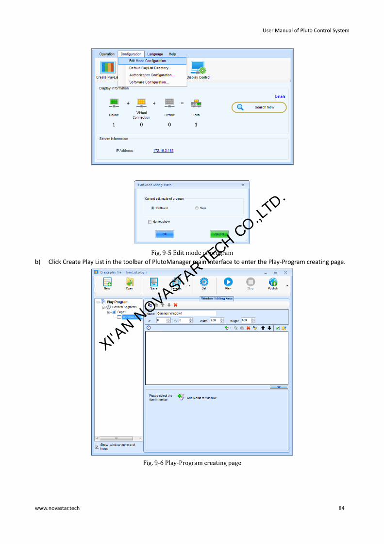
User Manual of Pluto Control System
www.novastar.tech 84
Fig. 9-5 Edit mode of program
b) Click Create Play List in the toolbar of PlutoManager main interface to enter the Play-Program creating page.
Fig. 9-6 Play-Program creating page
XI'AN N
OVASTAR TE
CH CO.,LTD.

User Manual of Pluto Control System
www.novastar.tech 85
9.2.1 Play program structure
Play program can save as the file which extension is .plpym, it is composed by several common segments,
otherwise, it can also contain one or more inserted segments. The common segment and inserted segment is
composed by one or more pages, and each page is composed by one or more windows. The window can be
divided into Common Window, Clock Window, Scroll Text Window, Countdown Timer Window, and Weather
Window. The Common Window can contain one or more different types of media. One example of play program
structure is as shown in the following figure.
Fig. 9-7 Example of play program
Common Segment
The segment has these time properties: Effective Date, Effective Days of the Week, Effective Time of the Day.
For Example: The common segment Segment1, from June 23, 2012 to June 30, 2012, every Monday,
Wednesday, Friday, played from 8:00 to 12:00, as shown in the following figure.
Fig. 9-8 Common segment 1
Timing Inserted Segment
The segment is started to play for specific times or duration at a specific time point in effective days of effective
date. It has these time properties: Effective Date, Effective Days of the Week and several Specific Time Points.
For Example: Timing inserted segment Segment2, from June 23, 2012 to June 30, 2012, every Monday, Wednesday,
and Friday, played at 8:30 for 1 times, as shown in the following figure.
XI'AN N
OVASTAR TE
CH CO.,LTD.

User Manual of Pluto Control System
www.novastar.tech 86
Fig. 9-9 Timing inserted segment2
Cycle Inserted Segment
The segment is played for specific times or duration at regular intervals in effective time of effective
days of effective date. It has these time properties: Effective Date, Effective Days of the Week, Effective Time of
the Day and Play Intervals.
For Example: Cycle inserted segment Segment3, from June 23, 2012 to June 30, 2012, every Monday,
Wednesday, Friday, from 8:00 to 12:00, played one time every 30 minutes, as shown in following figure.
Fig. 9-10 Cycle inserted segment inserted segment 3
Page
A page is an area on the computer display screen that is mapped to a LED display for showing visible media
sources (such as videos, pictures and text) on the LED display.
Global page
Global page is a special common page that it always stays on the front of all other common pages. In the case that
common pages of different window layout are needed while a window at a fix position is also required (such like
that for clock, weather info or scrolling text), putting the fix position window in a global page is the best way for
the window layout design. But if only one common page is needed, a global page may not be necessary as the fix
position window can be set directly to the position required.
XI'AN N
OVASTAR TE
CH CO.,LTD.

User Manual of Pluto Control System
www.novastar.tech 87
Common Page
A common page can have multiple windows and the layout of the windows can be customized. A segment can
have multiple pages. And of course, the window layouts of these common pages can be different from each other.
The common pages will be shown in the order they are listed in the segment. Normally, one common page is
enough for a segment.
Window
A window, also named a play window, is an area of a page in which visible media sources will be show. Note that
any window must be affiliated to a page.
Common Window
A common window could have its own media sources list and thus different types of media sources can be played
in it in the list order.
Scroll Text Window
A window that is only for showing scrolling text.
Clock Window
A window that is only for analog or digital clocks.
Countdown Timer Window
A window that is only for showing information from a time meter.
Weather Window
A window that is only for showing weather information.
9.2.2 Play program dispatch rule
If there are conflicts between the playing times of segments, follow the below rules:
1) The back one has the higher priority for the same type segments. 2) If the timing inserted segment has the same playing time point as the cycle inserted segment, play the
timing inserted segment.
You can view the dispatching result between different dates in the Play Program Editing Area.
For example:
Common Segment
Suppose time properties of segment A and segment B are set as follow:
A B
From June 24, 2012 to June 30, 2012 From June 24, 2012 to June 30, 2012
Every day in a week Every day in a week
From 8:00:00 to 15:00:00 in each day From 8:00:00 to 12:00:00 in each day
If B is at the back of A in the play program, then B has the priority to be played on time confliction (on March 23, 2015).
Fig. 9-11 B has higher priority than A
Otherwise, if A is at the back of B in the play program, then A has the priority to be played on time confliction (on March 23, 2015).
XI'AN N
OVASTAR TE
CH CO.,LTD.

User Manual of Pluto Control System
www.novastar.tech 88
Fig. 9-12 A has higher priority than B
Timing Inserted Segment
Suppose time properties of timing inserted segment C and timing inserted segment D are set as follow:
C D
From June 24, 2012 to June 30, 2012 From June 24, 2012 to June 30, 2012
Every day in a week Every day in a week
At 8:00, 15:00 At 9:00, 15:00
If D is at the back of C in the play program, then D has the priority to be played at the same time point (on March 23, 2015).
Fig. 9-13 D has higher priority than C
Otherwise, if C is at the back of D in the play program, then C has the priority to be played at the same time point (on March 23, 2015).
Fig. 9-14 C has higher priority than D
Cycle Inserted Segment
Suppose time properties of cycle inserted segment E and cycle inserted segment F are set as follow:
E F
From June 24, 2012 to June 25, 2012 From June 25, 2012 to June 26, 2012
Every day in a week Every day in a week
Play Interval: 30 minutes Play Interval: 30 minutes
If F is at the back of E in the play program, then F has the priority to be played on time confliction:
XI'AN N
OVASTAR TE
CH CO.,LTD.

User Manual of Pluto Control System
www.novastar.tech 89
Fig. 9-15 F has higher priority than E
Otherwise, if E is at the back of F in the play program, then E has the priority to be played on time confliction:
Fig. 9-16 E has higher priority than F
Note: If there is no confliction between two cycle inserted segments, but they has the same playing time point, still
follow the same dispatch rule(the back one has higher priority).
For Example, suppose time properties of G and H are set as follow:
G H
From June 24, 2012 to June 25, 2012 From June 24, 2012 to June 25, 2012
Every day in a week Every day in a week
Play Interval: 20 minutes Play Interval: 10 minutes
If H is at the back of G, H will be played at 00, 20, 40 minutes of every hour. Otherwise, play G.
If one time point of timing inserted segment is the same as one playing time of cycle inserted segment, play timing
inserted segment.
For example, suppose time properties of cycle inserted segment I and timing inserted segment L are set as follow,
it would play L when arrived at 10:30.
I L
From June 24, 2012 to June 25, 2012 From June 24, 2012 to June 25, 2012
Every day in a week Every day in a week
Play Interval: 30 minutes At 10:30
9.2.3 Display window setting
Click New button in the window of create play file to set the play window information.
XI'AN N
OVASTAR TE
CH CO.,LTD.

User Manual of Pluto Control System
www.novastar.tech 90
Fig. 9-17 Play window information
Play window resolution
Auto: Width and Height can adapt to the display automatically.
Customized size: Must be set according to the actual size of the display.
Select Display: Select display from the display list, to read the size of the client display directly.
Select Display operation steps:
a) Click Select Display in Fig. 9-17.to enter the terminal list.
XI'AN N
OVASTAR TE
CH CO.,LTD.

User Manual of Pluto Control System
www.novastar.tech 91
Fig. 9-18 Read display size of specific client
b) Select specific display, and click OK. The software will read the size of the client display directly.
9.2.4 Configure playlist directory
After clicking save in playlist creating page, the playlist will be automatically saved to default directory (factory
default: My Documents\NovaPluto\ PM-PlayList). The user can configure the directory of playlist. Re-configuration
of playlist directory might cause unsuccessful playlist publishing, therefore, users are recommended to read the
contents of this section carefully.
Operating steps of configure playlist directory:
1) Click Configuration button in the main interface of PlutoManager. The following window will pop up:
Fig. 9-19 Configure playlist directory
2) Click , warning window will pop up:
Fig. 9-20 Playlist directory changing warning
“Previously saved playlist cannot be used again after changing directory”means after the directory is changed,
clicking Open button will lead to the new directory to search for playlist. The playlists previously saved in the
default directory will no longer be opened, therefore cannot be used. So users are recommended to configure
directory before saving playlist.
3) Click Yes to choose a new directory. And then click OK. New directory will be configured successfully.
XI'AN N
OVASTAR TE
CH CO.,LTD.

User Manual of Pluto Control System
www.novastar.tech 92
9.2.5 Edit play program
9.2.5.1 Edit Segment
a) Create
Click the button on the toolbar of Play Program Editing Area, or right-click on the Play Program Node, or right-click
on the screen, a menu pops up shown as Fig. 9-21 for adding new segment.
Fig. 9-21 Add segment
b) Editing properties of segment
You can edit the properties at the Segment Editing Area after adding the common segment or inserted segment.
Shown as below.
Fig. 9-22 Properties page of common segment
XI'AN N
OVASTAR TE
CH CO.,LTD.

User Manual of Pluto Control System
www.novastar.tech 93
Fig. 9-23 Properties page of timing inserted segment
You can add one or more playing time point for the timing inserted segment.
For inserted segment, if Pause current play when playing inserted segment is selected, the current common
segment play (If has) would be paused and hide if begin to play inserted segment, otherwise, the inserted
segment and the current common segment would be played together.
Fig. 9-24 Properties page of cycle inserted segment
Use the toolbar on the right or right-click menu, you can copy, paste, move or delete the selected segment. The
toolbar and menu is shown as below.
XI'AN N
OVASTAR TE
CH CO.,LTD.

User Manual of Pluto Control System
www.novastar.tech 94
Fig. 9-25 Menu of segment
9.2.5.2 Page editing
1) Create a new page
Click the button on the toolbar at Segment Editing Area to add a Common Page or Global Page.
Fig. 9-26 Add page
2) Properties setting
The properties of the added page can be set through the property panel. Shown in Fig. 9-27 is the property panel.
Fig. 9-27 Properties of page
There are three options for Play Type, Cycle, Specific Times and Specific Duration. If Play Type is set to be Cycle,
this page will be shown repeatedly; if Specific Duration, NovaStudio2012 will shift to the next page after showing
this page for the time specified by Play Duration; if Specific Times, NovaStudio2012 will shift to the next page after
all the play windows finish playing their media sources repeatedly for N times (N is specified by Play Times).
Area of the page that is not covered by windows will show the background picture or color, as shown in Fig. 9-28.
Fig. 9-28 Background with background picture
The play type is only Cycle for global page. The global page will be always playing during the segment playing.
XI'AN N
OVASTAR TE
CH CO.,LTD.

User Manual of Pluto Control System
www.novastar.tech 95
Use the toolbar on the right or right-click menu, you can copy, paste, move or delete the selected page. The
toolbar and menu is shown.
Fig. 9-29 Menu of page
9.2.5.3 Window editing
1) Create a new window
After adding a page, you should add windows to the page. For example, click the button shown in Fig. 9-30 to add
a common window to the page.
Fig. 9-30 Add window to page
The newly added window will be shown on the computer display after the add operation, as shown in Fig. 9-31.
XI'AN N
OVASTAR TE
CH CO.,LTD.

User Manual of Pluto Control System
www.novastar.tech 96
Fig. 9-31 Added window
2) Window position and size setting
The position and size of a newly added window may need to be reset as the default values are unlikely to meet the
requirements. These values can be reset directly by using the tool provided in NovaStudio2012, as shown in Fig.
9-31. A more intuitive way to reset these values is to use the mouse. Click on the window to put focus on it and
then set its position and size by drawing, pulling and squeezing, as shown in Fig. 9-32. The arrow keys and their
combination with Shift keys can also be used for the position and size setting of a window.
Fig. 9-32 Tools for window position and size setting
Fig. 9-33 A focused common window
To show all the windows of a page, just select the page from the page list. This could be very helpful for windows
layout adjustment.
Fig. 9-34 Showing all window of page
3) Delete a window
To delete a specified window, click the circled Delete button, as shown in Fig. 9-35.
XI'AN N
OVASTAR TE
CH CO.,LTD.

User Manual of Pluto Control System
www.novastar.tech 97
Fig. 9-35 Delete window
4) Move a window
For overlapped windows in the same page, the one at front will cover those under it.
Suppose a common window and a clock window is added to a page at the same position of (0, 0, 200, 200) . The
common window will cover the clock window when this page is on shown if the common window is in front of the
clock window in the window list. To avoid the clock window being covered by the common window, move it to the
front of the common window or move the common window to the back of it. The circled arrow buttons in Fig.
9-36 are used to move a window forward or backward.
Fig. 9-36 Move window
5) Duplicate a window
To duplicate a window, select the source window, click the Copy button and then click the Paste. Circled in Fig as
below are the Copy button and the Paste button.
Fig. 9-37 The Copy button and the paste button
The right-click menus on the window node and on the window zone in the screen are also supported to edit the
window, as shown below.
Fig. 9-38 Right-click menu of window
XI'AN N
OVASTAR TE
CH CO.,LTD.

User Manual of Pluto Control System
www.novastar.tech 98
9.2.5.4 Media editing
Media editing will be illustrated with a common window as an example.
1) Add a media
Media sources of a media type that is supported by the Software can be added to a common window for showing.
Click the button “Add Media” to access the drop-down menu of media types. Select the corresponding item to add
a media source of that type to the common window.
Fig. 9-39 Add media
2) Media properties setting
Properties of a media source can be set is related to the type of the media source. Refer to <Media Types
Supported by Pluto Manager> for information about the settable properties of a certain type of media.
Settable properties of the selected media item in the media source list will be shown on the property panel, as
shown in Fig. 9-40. Modify the property settings of a media item through the property panel if required.
Fig. 9-40 Properties page of media
XI'AN N
OVASTAR TE
CH CO.,LTD.

User Manual of Pluto Control System
www.novastar.tech 99
3) Set play times of media
Select the media in the list, then double click the Play Times Grid to change the play times: You can manually enter
a new number or select the existing number in the drop-down, as shown.
(1)
(2)
Fig. 9-41 Change play times of media
The media scheduling is related with the play type of current page, described as follows.
If there is three media A, B and C of one common window, the corresponding play time is 1, 2 and Any Times, the play order is as follows:
The play type of page is Cycle: A B C B C C C C……
The play type of page is Specific Times as 2:A B C B | A B C B
The play type of page is Specific Duration:A B C B C C C C…… If there is three media A, B and C of one common window, the corresponding play time is 1, 2 and 3, the play
order is as follows:
The play type of page is Cycle: A B C B C C | A B C B C C | A B C B C C |……|……
The play type of page is Specific Times as 2:A B C B C C | A B C B C C
The play type of page is Specific Duration:A B C B C C | A B C B C C |……|……
4) Preview a media
Click a media item in the media list to preview it in the current window (in this case, the current window is a
common window). New property settings will take effect immediately even they are set during the previewing.
The first media source in the media list of a window will be automatically previewed when the window is selected.
5) Move a media item
Use the buttons to move a media item in the media list forward or backward and thus change the play
order of the media sources. Mouse can also be used to move media items. The red line in Fig. 9-42 indicates the
new position of the mouse item dragged by the mouse.
Fig. 9-42 Move a media item by mouse
6) The copy and paste of media
XI'AN N
OVASTAR TE
CH CO.,LTD.

User Manual of Pluto Control System
www.novastar.tech 100
Click button to copy the selected media, and click button to insert the copied media after the
selected media.
7) Apply the media properties to others
Select a media, and then click button ,choose the media to apply to in the pop up dialog.
Fig. 9-43 Apply properties to media
Otherwise, the media operation also provides the corresponding right-click menu, as shown.
Fig. 9-44 Right-click menu of selected media
XI'AN N
OVASTAR TE
CH CO.,LTD.

User Manual of Pluto Control System
www.novastar.tech 101
Fig. 9-45 Right-click menu of blank zone
9.3 Making sign list
Edit mode needs to be configured first. The operating steps are: click "Configuration" →"Edit Mode
Configuration"→"Sign"→ "OK".
XI'AN N
OVASTAR TE
CH CO.,LTD.

User Manual of Pluto Control System
www.novastar.tech 102
Fig. 9-46 Edit mode configuration
Begin to make Sign list according to the following steps.
Fig. 9-47 Sign play list edit page
9.3.1 Introduction to Toolbar
Set play window. Click to set play window.
XI'AN N
OVASTAR TE
CH CO.,LTD.

User Manual of Pluto Control System
www.novastar.tech 103
Fig. 9-48 Set play window information
Method one: check "Auto", click "Select Display" to select the client, and direct read the size of the load display
screen of the client and take it as the size of the play window.
Method two: check "Manual (Custom size)", and fill in the size of the play window.
9.3.2 Edit play list
The edit homepage of Play List is divided into multiple windows, and each window is named according to its
function, as shown in the following figure.
Fig. 9-49 Page function distribution
1) Page adding or deleting, sorting window
Click to add the page, select Page Layout at the drop-down box at the right of the screen, and amend the
proportion by clicking the buttons Up, Down, Left and Right based on requirements.
XI'AN N
OVASTAR TE
CH CO.,LTD.

User Manual of Pluto Control System
www.novastar.tech 104
Fig. 9-50 Page adding or deleting sorting layout window
2) Page adding media window
Select one window of the page, and then click button on the toolbar to add media to the window.
Click to simulate the real display screen to view the distribution situation of pixels.
XI'AN N
OVASTAR TE
CH CO.,LTD.

User Manual of Pluto Control System
www.novastar.tech 105
Fig. 9-51 Page adding media window
Fig. 9-52 Screen after 3 times of amplification
3) Play and media attribute edit window
When adding the media, simultaneously set attribute of the media and the play effect at the window.
4) Select sign
Click , the window for select sign will showing or hiding, Check "Select sign", and then select the display
to play the page.
5) Scheduled
a) Click Schedule to check "Scheduled date" to set play date of list, and click to increase or decrease the time.
Fig. 9-53 Set scheduled date
XI'AN N
OVASTAR TE
CH CO.,LTD.

User Manual of Pluto Control System
www.novastar.tech 106
b) Click "TIME" to set the play time of List, available options are All day, point-in-point or Time slot.
When "Point-in-point" play is selected, click to select the point-in-time, double click to cancel; the
default is to play for one hour from the selected point in time; for example, three points-in-time are
selected in the following figure - 12 AM, 3 AM and 8 AM; then the play scheduled dates are:
Play from 12 AM to 1 AM; Play from 3 AM to 4 AM; Play from 8 AM to 9 AM.
Fig. 9-54 Set point-in-time
When "Time slot" play is selected, click to increase or decrease the time segments.
Fig. 9-55 Set time slot
c) Click "WEEKDAY" to set the day in the week to play List.
Fig. 9-56 Set weekday
d) Play times
XI'AN N
OVASTAR TE
CH CO.,LTD.

User Manual of Pluto Control System
www.novastar.tech 107
e) Select “Client”
Click “Select the client” to select terminals on the page.
Note: Each page can be played on different clients.
If “Select the client” is not enabled, this page may be displayed on several clients.
Fig. 9-57 Select clients
f) View Scheduled date
Click to view the Scheduled date.
Fig. 9-58 View Scheduled date by day
Fig. 9-59 View Scheduled date by period
XI'AN N
OVASTAR TE
CH CO.,LTD.

User Manual of Pluto Control System
www.novastar.tech 108
Fig. 9-60 View Scheduled date by time segment
9.3.3 Sending play list
Click on the toolbar, with the software prompting saving list first, then sending. User operates by following
the software prompts.
9.4 Publish playList
9.4.1 Online publish
Online publish means publishing Play-Program directly to the client (who’s online) storage space through network.
Operation Steps:
1) Go back to the main interface of PlutoManager. Click Publish PlayList button to enter the PlayList Publish page.
XI'AN N
OVASTAR TE
CH CO.,LTD.

User Manual of Pluto Control System
www.novastar.tech 109
Fig. 9-61 Play-Program publishing page
Refresh: press to view all finished Play-Programs;
Clear: delete all Play-Programs and files;
Delete: once deleted, all files related to Play-Program will be gone no matter converted or not;
Send: send Play-Program;
Export: export Play-Program to USB disk.
2) Select the Play-Programs you want to convert, press“Ctrl”at same time to select multiple, right click, and select Convert. The following window will pop out. click "Advanced" You can set the parameters in detail, if no advanced settings, the video will be converted with the default parameters.
XI'AN N
OVASTAR TE
CH CO.,LTD.

User Manual of Pluto Control System
www.novastar.tech 110
Fig. 9-62 Edit parameter of convert video
3) After the conversion is completed, it will be shown as below.
XI'AN N
OVASTAR TE
CH CO.,LTD.

User Manual of Pluto Control System
www.novastar.tech 111
Fig. 9-63 Play-Program conversion result
4) Press to publish successfully converted Play-Program, and will enter the window as shown below.
XI'AN N
OVASTAR TE
CH CO.,LTD.

User Manual of Pluto Control System
www.novastar.tech 112
Fig. 9-64 Parameters of online send
Select by client: Directly check the client (who’s online) which Play-Program will be sent to;
Select by group: Publish Play-Program by group;
Attention:
If the size of terminal screen is different from playback program, and the users still send this playback to the screen,
the system will adopt the self adapting window playback, but this will lead to the terminal screen become
deformed.
5) Click "Next" to enter the following page;
Fig. 9-65 Play- Program online publish page
XI'AN N
OVASTAR TE
CH CO.,LTD.

User Manual of Pluto Control System
www.novastar.tech 113
Note: Synchronize the terminal time as required, and the current time of the computer is sent to the terminal while
the program is sending during terminal time synchronization.
6) You are advised to tick Pause client playing while sending media and choose where to save Play-Program in client. Click "Advanced"to publish, after successfully publishing, below window will be shown.
Fig. 9-66 Play-Program publishing successfully
Attention:
In case of single group and single client, click to skip to the page as shown in fig.9-65, and then click “Next”.
9.4.2 Offline export
Offline export means to export current Play-Programs to USB disk first, and then connect to client and play.
Operation steps:
1) Press excert button in Fig. 9-63 to enter offline export settings page.
Fig. 9-67 Offline export settings
XI'AN N
OVASTAR TE
CH CO.,LTD.

User Manual of Pluto Control System
www.novastar.tech 114
Play after copying Play-Program to other storage device: under this mode, after connecting USB disk to client,
Play-Programs and programs will be copied to selected storage device before playing.
Play without copying: under this mode, after connecting USB disk to client, Play-Programs and programs will be
played directly without copying to other storage device.
2) After setting, press Export to export current Play-Program to USB disk.
Fig. 9-68 Export succeed
9.4.3 Publish temporary content
Emergency insert play means to insert some media or Play-Programs which need to be played urgently on the
client display during normal playing. Instant play and delay play are optional by the degree of urgency. Delay time
can be set freely.
Return to Play-Program publish main interface, as shown in figure 9-63. Click the Publish Temporary Content enter
the emergency insert play page;
Fig. 9-69 Publish temporary content page
Content type: File, Playlist;
Window size: Size of the current client display;
Play duration: Total play time of inserted media file or Play-Program.
Start time
Immediate: Inserted media file or Play-Program will be played immediately once successfully published;
XI'AN N
OVASTAR TE
CH CO.,LTD.

User Manual of Pluto Control System
www.novastar.tech 115
Delay: The playing will be delayed for a period of time after successful publishing, the delay time can be set.
Attention:
A. Window size must be the real size of the current client display, so when media files are added, and you don’t know the size of the display, it can be read directly by choosing client.
B. For insert play, it shall also be considered that whether the window size of Play-Program is same to the size of the display. If they are different, need to edit first.
Operating steps of insert file:
1) Click button to select the media files (images, video, audio, documents) need to be inserted, as shown below.
They are editing interfaces of insert pictures, video and audio etc.
Fig. 9-70 Insert pictures
Fig. 9-71 Insert video
Fig. 9-72 Insert text file
XI'AN N
OVASTAR TE
CH CO.,LTD.

User Manual of Pluto Control System
www.novastar.tech 116
2) After inserting media files, click OK to return to the emergency insert play page as shown in Fig. 9-69. Click Choose Display to read the display size of client who need the insert play. Select insert start time and duration;
3) After setting of insert play options, click Publish button at the bottom of the page. Edit parameter of convert video window will pop up, as shown in Fig. 9-62. Choose the video effect to be converted to, and click OK. After conversion is completed, the following window will pop up:
Fig. 9-73 Insert play files converted to Play-Program
4) Click OK to enter the online publish page as shown below. Select the client who need the insert play (who’s also online). Click Next,
5) Check Play-Program and client list to be published. Make sure they are correct, then click Publish. When publish result shows Succeed, it means insert play files have been successfully published to the client.
Operating steps of insert playList
Select PlayList in Fig. 9-69 Emergency insert play page, and click to insert PlayList. The following steps are
same to those of insert files.
9.4.4 Immediate notification
Immediate notification mainly releases some text information. Once successfully published, current information
will be played on the client display immediately, prior to all other tasks.
Return to Play-Program publish main interface. Click Immediate Notification. The page is as shown below: XI'AN N
OVASTAR TE
CH CO.,LTD.

User Manual of Pluto Control System
www.novastar.tech 117
Fig. 9-74 Immediate notification page
Position: Position of immediate notification textbox on the display;
Width: Textbox width ≤ window width;
Height: Textbox height ≤ window height; Left edge: If the upper left corner of the window is (0, 0), the left edge value is the distance between left
edge of textbox and left edge of the window, i.e. x coordinate. Left edge ≤ window width - textbox width; Top edge: Upper edge value is the distance between the upper edge textbox and the upper edge of the
window, i.e. y coordinate. Upper edge ≤ window height - textbox height;
Play mode:
Loop times: Set loop times of immediate notification Play duration: Play duration of immediate notification
Text type:
Scrolling text: Editable text, transparent, background, text effects, text color, font, loop, scrolling speed, play duration, etc.
Single line text: Editable text, transparent, background, text effect, font, entrance/exit effect, retention time, etc.
Static text: Editable text, transparent, background, paragraph, font, play duration, etc. Complex text: Text editor, transparent, background, entrance/exit effect, retention time, etc.
Operating steps of immediate notification:
1) Edit textbox size, coordinates, content, and text format in immediate notification page; 2) Click Publish after editing. Choose Video Conversion Quality window will pop up. Select the quality you want
to convert; 3) After conversion is completed, the page will be as shown below:
XI'AN N
OVASTAR TE
CH CO.,LTD.

User Manual of Pluto Control System
www.novastar.tech 118
Fig. 9-75 Instant notification convert to Play-Program
4) Click OK to enter the online publish page. The following steps are same to online publish.
9.5 Play management
Play management includes play control, log management and storage management, to help users know the
current play status and external storage condition of client timely,.
9.5.1 Play control
9.5.1.1 Control play
Enter the play control page directly by clicking Play management in the main interface, as shown below. On the
left is client list. Select a client to control play status of it.
Fig. 9-76 Play control page
XI'AN N
OVASTAR TE
CH CO.,LTD.

User Manual of Pluto Control System
www.novastar.tech 119
Play control:
Play: Enable the client display start to play Pause: Pause the current playing Stop: Stop the current playing Stop Temporary Content: Cancel the inert play task Stop Emergency Message: Cancel the immediate notification
Current play information: User can refresh to get the current playing status of current client;
Just select a terminal and click Read button, the current play information of the selected terminal will be shown.
Fig. 9-77 Current play information
Screen shot: Click to get the real-time play image of the current client;
Just select a terminal and click Read button, the current play image of the selected terminal will be shown,click
for a larger view.
Fig. 9-78 Screen shot
9.5.1.2 Synchronized play
Terminals, of which synchronized play functions, are subject to play programs, and require time setting for the
unified time. Refer to 9.8 Terminal time synchronization for time setting procedures.
Select terminal in the terminal list, and enter secret code“admin” or “888”through the keyboard to enter the
following page. Select “Enable synchronized play” and then “Apply” to enable the synchronized play.
XI'AN N
OVASTAR TE
CH CO.,LTD.

User Manual of Pluto Control System
www.novastar.tech 120
Fig. 9-79 Synchronized play
9.5.2 Log management
User can set valid days of log storage and view log of specific period of time in log management page.
Fig. 9-80 Log management page
Set number of storage days: The user can set freely, but it shall not be more than 31 days. After the setting, click
Apply to take effect. Click Read to view the current setting;
Log operation: User can set the start and end date, check Getting existing log again, and then Read to obtain log
list of corresponding period of time.
XI'AN N
OVASTAR TE
CH CO.,LTD.

User Manual of Pluto Control System
www.novastar.tech 121
9.5.3 Storage management
Media Play-Programs are all stored in the hardware or removable storage devices of client. In order to avoid
failure of sending or loss of media due to lack of space, user shall maintain storage device space regularly.
Space utilization of media storage devices of each client can be viewed in storage management page. All media,
expired media and all lists can be deleted. Please manage the remaining space of storage devices timely.
Fig. 9-81 Storage management page
Read: read total storage space and available space of client storage devices;
Delete all media: Delete all the media files of the current media storage device;
Delete Outdate media:
Media files not used by the current play program are considered as expired media. Click on this button will delete
all expired media files.
9.6 Display control
The display control includes System Configuration, Network Configuration, Server Configuration,Brightness
Adjustment and Power Schedule.
XI'AN N
OVASTAR TE
CH CO.,LTD.

User Manual of Pluto Control System
www.novastar.tech 122
In addition: The order of the sub-options can be adjusted; for example, click "Network Configuration" and press
left click to drag around.
9.6.1 Network configuration
When modifying network parameters of the current terminal, set the terminal IP under "Network
Configuration"→"Wired Configuration" as following methods:
Fig. 9-82 Wired configuration
Click “Read” to read the current IP.
Remote Change of Terminal IP
Method 1: Tick “Obtain an IP address automatically (Recommended)” and the click “Apply”.
Method 2: Change the parameter manually, and then click “Apply”.
When IP is successfully set, the terminal will automatically disconnect, and then reconnect.
9.6.2 System configuration
9.6.2.1 Time management
The time error may occur on terminal after a long time work, or the time shall be adjusted after the asynchronous
card is replaced.
Under system control interface, users can read the current client time and time zone, check out the time of
selected zone, apply the time zone to the terminal
For example: select a time zone” Central America”, To show the time of this time zone. click【Read】button, to read
client time and client time zone , and the window is as follow:
XI'AN N
OVASTAR TE
CH CO.,LTD.

User Manual of Pluto Control System
www.novastar.tech 123
Fig. 9-83 Time management page
Click 【Apply to display】, The message of “Set client system succeed” indicates client time correctly set. Click
【Read】 button and you will see the terminal time is the same as that of the time zone.
Fig. 9-84 Adjust time
XI'AN N
OVASTAR TE
CH CO.,LTD.

User Manual of Pluto Control System
www.novastar.tech 124
9.6.2.2 Reboot the display
Fig. 9-85 Display reboot
Reboot immediately: select the display, and click “Reboot Immediately” button to reboot the current display.
Schedule to reboot
Click “Read” to view whether the current terminal is set as clocked restart.
If yes, the reboot time can be altered; if no, please tick “Enable scheduling to reboot” to set the reboot time;
finally click “Apply” to send the reboot command to the asynchronous card.
9.6.2.3 Display password configuration
Input "admin" at the interface of "System Configuration" to display the terminal password setting interface, as
shown in the following figure. As no password has been set for the terminal, input a password is displayed in the
interface; if the password has been set previously, the password can
be cancelled or changed.
XI'AN N
OVASTAR TE
CH CO.,LTD.

User Manual of Pluto Control System
www.novastar.tech 125
Fig. 9-86 Enter password
Fig. 9-87 Cancel or modify password
After entering the password, you can come to the next page to configure the default client background.
XI'AN N
OVASTAR TE
CH CO.,LTD.
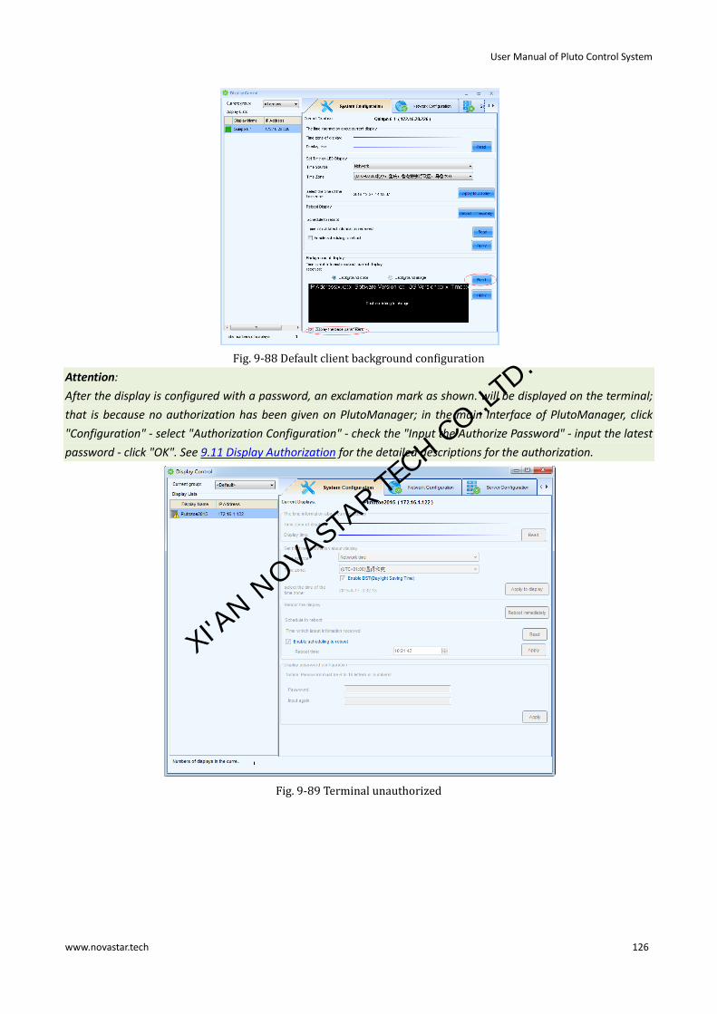
User Manual of Pluto Control System
www.novastar.tech 126
Fig. 9-88 Default client background configuration
Attention:
After the display is configured with a password, an exclamation mark as shown. will be displayed on the terminal;
that is because no authorization has been given on PlutoManager; in the main interface of PlutoManager, click
"Configuration" - select "Authorization Configuration" - check the "Input the Authorize Password" - input the latest
password - click "OK". See 9.11 Display Authorization for the detailed descriptions for the authorization.
Fig. 9-89 Terminal unauthorized
XI'AN N
OVASTAR TE
CH CO.,LTD.

User Manual of Pluto Control System
www.novastar.tech 127
9.6.3 Server configuration
Fig. 9-90 Server Configuration
Read: read the current server configuration of the display.
Set the interface as shown in figure 9-90 as required. Connection status can be the current status to make
communication check and problems locating easy.
The connection parameters of PlutoManager
Static IP address: the local IP of the control computer.
Server parameters configuration:The domain name of the Server which PlutoManager connected with.
Connection port: adopt the default settings to ensure that the port can't be taken up by other software (in the
main interface of PlutoManager, click "Configuration" - "Software Configuration" and then set the connection
port).
The connection parameters of NovaCloud configuration
Server address:Select the server address from the three choices.
Customer ID: Defaults to Cloud. It cannot be modified.
User name: Fill in the user name.
MAC address: It is one of the requirements when the display sign up to NovaCloud.
The Parameters of Cloud Monitoring configuration:
User name: Fill in the user name registered in NovaiCare, the terminal will be registered under the user name
after filling.
Set: After the server parameter is set, click "Set" to apply that to the terminal.
XI'AN N
OVASTAR TE
CH CO.,LTD.

User Manual of Pluto Control System
www.novastar.tech 128
9.6.4 Brightness adjustment
9.6.4.1 Manual brightness
Pull the bar can adjust the display brightness, which will be automatically applied to the terminal display screen.
Click "Save" to save the brightness setting to the hardware, where the brightness will not be lost when the power
is cut off.
Fig. 9-91 Manual adjustment
9.6.4.2 Scheduled brightness
The Schedule brightness adjustment shall not be set on NovaPluto-LCT and PlutoManager simultaneously; if both
software have been set with the schedule adjustment, then the system will perform the final setting.
XI'AN N
OVASTAR TE
CH CO.,LTD.

User Manual of Pluto Control System
www.novastar.tech 129
Fig. 9-92 Scheduled adjustment
XI'AN N
OVASTAR TE
CH CO.,LTD.

User Manual of Pluto Control System
www.novastar.tech 130
9.6.4.3 Automatic brightness
Fig. 9-93 Auto brightness
Fig. 9-94 Auto adjustment
Click can enter advanced setting page. After entering the advanced setting page, users can fill
in the brightness values based on different environment brightness.
XI'AN N
OVASTAR TE
CH CO.,LTD.

User Manual of Pluto Control System
www.novastar.tech 131
Fig. 9-95 Advanced setting page of auto brightness adjustment
9.6.4.4 Smart brightness
By using smart brightness, the adjusting methods of scheduled brightness and automatic brightness can be
combined together for flexible application.
Fig. 9-96 Smart brightness
Click , add the adjustment scheme and click “OK” after editing.
XI'AN N
OVASTAR TE
CH CO.,LTD.

User Manual of Pluto Control System
www.novastar.tech 132
Fig. 9-97 Brightness editing plan
Two brightness programs are required to regularly adjust the brightness to 100% at 8 AM and automatically adjust
the brightness at 8 PM. Setting results are as shown in the following figure:
XI'AN N
OVASTAR TE
CH CO.,LTD.

User Manual of Pluto Control System
www.novastar.tech 133
9.6.5 Power schedule
9.7 Online upgrade
Operating steps of online upgrade of pluto client software:
1) Press Operation in PlutoManager main interface, select Display Upgrade, to enter below page. You can refresh to check the version of the selected display, or click “Refresh All” to refresh all the displays.
XI'AN N
OVASTAR TE
CH CO.,LTD.

User Manual of Pluto Control System
www.novastar.tech 134
Fig. 9-98 Online upgrade of pluto client software
2) Click to select path of upgrade package. 3) Upgrading of one display or all displays is optional.
9.8 Time synchronization
Keep the time of display consistent with that of the control computer, server, or display network through the time
synchronization.
1) Click operation on the main interface→Time Synchronization, to open the Display Time Synchronization window.
Fig. 9-99 Time synchronization
A unified set of time: Check the option to conduct the unified setting of all displays.
Time synchronization mode:
From PlutoManager: keep the time of display consistent with that of the PlutoManager computer (i.e.
XI'AN N
OVASTAR TE
CH CO.,LTD.

User Manual of Pluto Control System
www.novastar.tech 135
control computer) From MC-go Server: keep the time of terminal consistent with that of Cloud server, if the Cloud platform is
used. From network: time acquisition of display is from the network.
Read Selected / Read All: readback the current mode of the selected or all displays.
Apply to Selected/ Apply to all: Apply the time of the selected or all display to current settings.
2) Select the time synchronization mode for the display and apply to display.
3) Click button for time setting. Click OK when finish.
Fig. 9-100 TimeSyn setting
TimeSyn interval: For setting the time period according to which terminals’ time will be checked and reset.
Time source: Optional network time or computer time.
TimeSyn zone: For time zone setting.
9.9 Font management
Read and update current font of the display.
Fig. 9-101 Font management
XI'AN N
OVASTAR TE
CH CO.,LTD.

User Manual of Pluto Control System
www.novastar.tech 136
9.10 Language management
Update the terminal’s language.
Tick “Uniform Setting of Terminal Language” to select language type, and then click “Update All” to update the
language of all terminals.
Fig. 9-102 Language management
9.11 Display authorization
Encrypt the specified client, and the encrypted client cannot be connected at will by any other people so as to
protect the play security of client display.
9.11.1 Authorization
Authorization of the display can be conducted in two ways.
Way I: NovaLCT-Pluto terminal authorization
1) Password authorization
In the NovaLCT-Pluto main interface, click on【Setting】→【Client Authorized】,and enter password in the Play
Authorized Setting Window,and then click on【OK】.
XI'AN N
OVASTAR TE
CH CO.,LTD.

User Manual of Pluto Control System
www.novastar.tech 137
Fig. 9-103 Play authorized setting
2) Modify authorized
In the Play Authorized Modify Window, tick【Modify Authorized】,enter the newest password,and click on 【OK】.
And then, save the authorized file, and it is better to cover the previous authorized file of this client.
XI'AN N
OVASTAR TE
CH CO.,LTD.

User Manual of Pluto Control System
www.novastar.tech 138
Fig. 9-104 Modify authorized
3) Generating authorization documents
Once the password is set, click on 【Save to File】,to save the authorized file to the specified directory(it is
recommended to set a name allowing rapid identification as per clients for the authorized file).
Fig. 9-105 Saving authorized File
4) Cancel authorized
In the NovaLCT-Pluto main interface, click on【Setting】→【Client Authorized】,and at this moment, it is required
to enter password again,and then tick【Cancel Authorized】,and click on【OK】to cancel authorized.
Fig. 9-106 Cancel authorized
Way II: Pluto Manager terminal authorization
XI'AN N
OVASTAR TE
CH CO.,LTD.

User Manual of Pluto Control System
www.novastar.tech 139
See 9.6.2.3 Client password configuration for the specific operations.
9.11.2 Authorized decryption
1) NovaLCT
It shall be input the correct password when connecting the authorized terminal.
2) PlutoManager authorization configuration
If the terminal is set with a password or the password has been changed, then, the user has to input the latest
password or import the corresponding authorization document into PlutoManager; otherwise the connection
error may occur.
For example:previously, authorization has been set for LYZ,and in PlutoManager client list, you may see that this
client displays abnormal connection.
Fig. 9-107 Display status of client without authorization configuration
Solutions:
In the software main interface, click on【Configuration】→【Authorize file】,as shown below:
Fig. 9-108 Configure authorization information
Way I: Select "Import authorize file" option , then click on to import authorized file of LYZ, and click on
"OK".
WayⅡ: Select "Input authorize password" option, and click on "OK".
XI'AN N
OVASTAR TE
CH CO.,LTD.

User Manual of Pluto Control System
www.novastar.tech 140
After importing the authorized file, the display status of this client is normal, as shown below:
Fig. 9-109 Client display after authorization configuration
XI'AN N
OVASTAR TE
CH CO.,LTD.

User Manual of Pluto Control System
www.novastar.tech 141
10 Hardware Program Upgrade
Operation steps for updating hardware program in LCT:
Login as an advanced user, and input admin in the main interface of NovaLCT Pluto to open hardware program
loading page.
Attention:
A. There isn’t any place to view the typing when inputting the password. Just type in the password directly.
B. Just input the password again if you typed the wrong password.
C. Hardware program updating is not recommended if no problem occurs.
Fig. 10-1 Hardware program loading page
Program Path: Select the program to be loaded to the hardware.
Scan Board FPGA: Select this option to upgrade the FPGA program of a scan board.
Change: Click this button to load the selected program to the selected hardware.
Refresh All
If this option is selected, the version info of scan boards connected to the current serial port will be refreshed
when click the Refresh button.
Refresh One
If this option is selected, only the version info of the selected scan board will be refreshed when click the Refresh
button.
Refresh: Click this button to show the current version info of the hardware. This can be used to check whether the
hardware program has been upgraded.
XI'AN N
OVASTAR TE
CH CO.,LTD.

User Manual of Pluto Control System
www.novastar.tech 142
11 Frequently Asked Questions
1) Software shows “No Hardware”
Please check whether all the clients that currently connected are electrified.
2) Software shows “No Screen”
If the LED display has been configured already, then try to read the configurations from the display by click Read
from HW button in the Screen Configuration page, as shown in Fig.11-1. If the display has not been configured yet,
please configure it first.
Fig. 11-1 Read LED display info from hardware
3) Only part of the modules of each cabinet work normally in Smart Setting
Please check whether the size of the module array is correctly set.
Fig. 11-2 Smart setting step 1
4) Check whether the number of columns of lines in the figure are consistent with that of actual columns of lines of cabinets.
XI'AN N
OVASTAR TE
CH CO.,LTD.
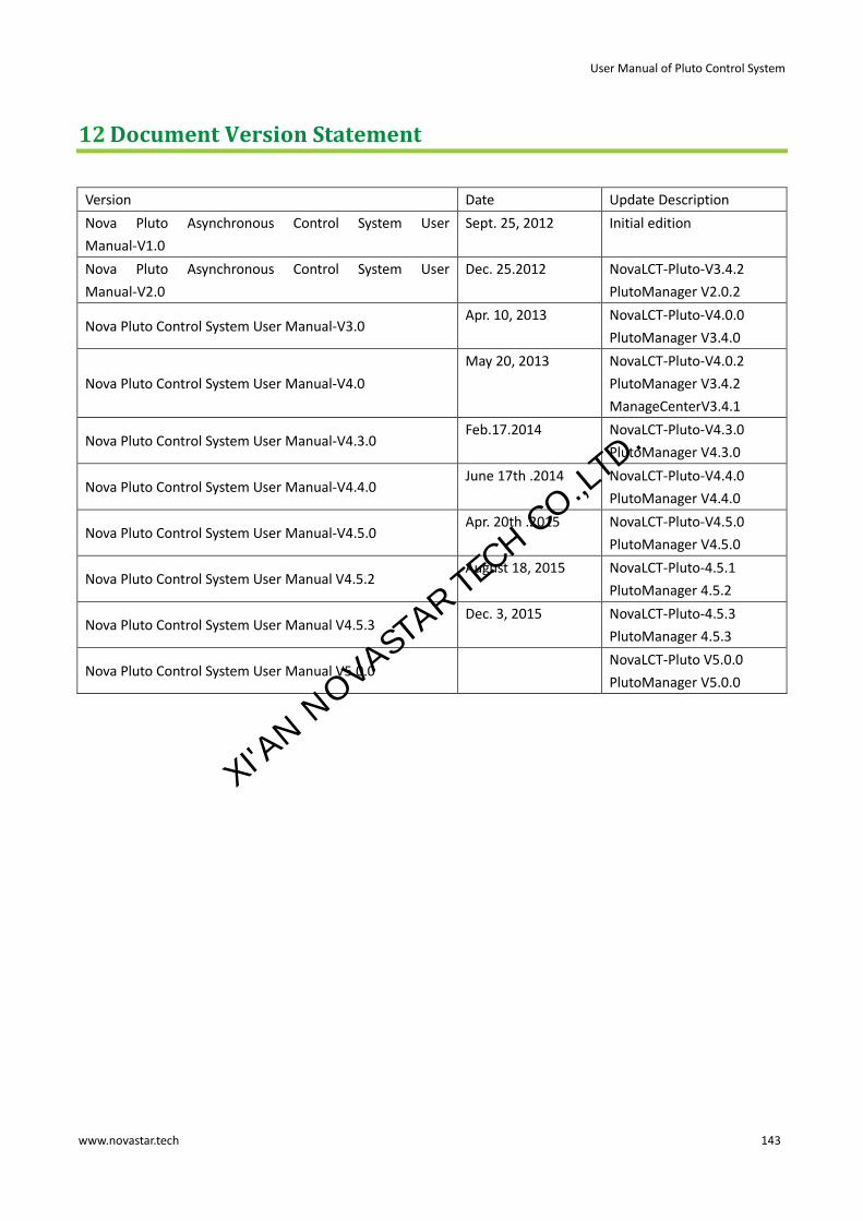
User Manual of Pluto Control System
www.novastar.tech 143
12 Document Version Statement
Version Date Update Description
Nova Pluto Asynchronous Control System User
Manual-V1.0
Sept. 25, 2012 Initial edition
Nova Pluto Asynchronous Control System User
Manual-V2.0
Dec. 25.2012 NovaLCT-Pluto-V3.4.2
PlutoManager V2.0.2
Nova Pluto Control System User Manual-V3.0 Apr. 10, 2013 NovaLCT-Pluto-V4.0.0
PlutoManager V3.4.0
Nova Pluto Control System User Manual-V4.0
May 20, 2013 NovaLCT-Pluto-V4.0.2
PlutoManager V3.4.2
ManageCenterV3.4.1
Nova Pluto Control System User Manual-V4.3.0 Feb.17.2014 NovaLCT-Pluto-V4.3.0
PlutoManager V4.3.0
Nova Pluto Control System User Manual-V4.4.0 June 17th .2014 NovaLCT-Pluto-V4.4.0
PlutoManager V4.4.0
Nova Pluto Control System User Manual-V4.5.0 Apr. 20th .2015 NovaLCT-Pluto-V4.5.0
PlutoManager V4.5.0
Nova Pluto Control System User Manual V4.5.2 August 18, 2015 NovaLCT-Pluto-4.5.1
PlutoManager 4.5.2
Nova Pluto Control System User Manual V4.5.3 Dec. 3, 2015 NovaLCT-Pluto-4.5.3
PlutoManager 4.5.3
Nova Pluto Control System User Manual V5.0.0 NovaLCT-Pluto V5.0.0
PlutoManager V5.0.0
XI'AN N
OVASTAR TE
CH CO.,LTD.