user’s manual cuplok - scaffolding solutions · pdf filemethod of safe erection of...
TRANSCRIPT

For further information on this product or any other products and services, please contact yourlocal branch:
tel: 08705 288 388 email: [email protected] www.sgb.co.uk
SGB GroupHarsco House, Regent Park, 299 Kingston Road, Leatherhead, Surrey KT22 7SG Tel: 01372 381300
1006/CDP/5K
CUPLOK USER’S MANUAL
SGB C
UPLO
K U
SER’S MA
NU
AL
SGB Cuplok cover 12/6/06 12:00 PM Page 1

CONTENTS
3
Page
Introduction 5
The CUPLOK locking procedure 6
CUPLOK safety information 7
General site safety 9
Core components 11Scaffold system components 12Ancillary components 17
Omega components for batten platforms 21
Typical tubular CUPLOK access layouts 25
Typical Omega access layouts 28
Safe Working LoadsTubular components 31Omega components 32
Bracing and Tying in 34
Maximum heights 35
Circular access 43
Loading platforms 47
Staircase towers 51
Towers 81
Support structures 83
2
445.33 CUPLOK USER'S MANUAL_12 12/6/06 11:34 AM Page 2

5
INTRODUCTION
SGB CUPLOK is the world’s most widelyused system scaffold. It is a fullygalvanised multi-purpose steel scaffoldsystem suitable for providing generalaccess and supporting vertical loads.CUPLOK’s key feature is its uniquecircular node point which allows up to 4 horizontals to be connected to avertical in a single fastening action -making it probably the fastest and safestsystem available.
The comprehensive range of CUPLOK components
allows it to be used with traditional scaffold boards
or battens. It can be used to create a huge range of
access and support structures, staircase towers,
circular scaffolds, loading towers and mobile
towers.
Hot-dipped galvanizing is the finest practical
coating that can be applied to a scaffold system,
providing a long working life and better handling.
SGB CUPLOK is manufactured to strict quality
standards, maintained and audited worldwide by
SGB’s Quality Control Department.
This manual has been designed to enable CUPLOK
users to become proficient in planning and erecting
conventional CUPLOK scaffolds. It provides
comprehensive details of components and guidance
on the design and erection of access and support
structures.
For further details on safe erection and dismantling
procedures, please refer to the relevant SGB User
Guide. Should you require further advice regarding
the design of more complex applications, please
contact your local SGB Branch on:
Tel: 08705 288 388
Important
As with all scaffolding, CUPLOK should only be
erected by trained personnel. SGB conducts a
range of courses covering all aspects of assembly
and inspection for aluminium towers, scaffold
systems and powered access. SGB provides
trainees with recognised qualifications and
certificates in association with the relevant
professional bodies.
Related literature
• CUPLOK Scaffold Systems brochure
• CUPLOK Staircase Tower brochure
• CUPLOK Scaffold System User Guide
• Scaffold Decking User Guide
• Scaffold Tube, Fittings, Steel and Aluminium
Beam User Guide
• SGB Guide to Formwork and Shoring
These brochures can be obtained from:
your local SGB Branch (Tel: 08705 288 388)
via www.sgb.co.uk or by e-mailing [email protected]
Associated SGB products
SGB supplies a comprehensive range of access and
support systems as well as general site safety
products, groundworks and powered access
equipment including:
• Traditional tube and fittings
• Aluminium and GRP mobile access towers
• Aluminium, steel and GRP ladders and steps
• Low level mobile platforms and access systems
• Heavy duty storing systems for wall and soffit
support
• Edge protection systems including EXTRAGUARD
and ROOFGUARD
• Scissor lifts, mobile booms and mast-climbing
platforms
• Site safety products
4
445.33 CUPLOK USER'S MANUAL_12 12/6/06 11:34 AM Page 4
76
THE CUPLOK LOCKING PROCEDURE
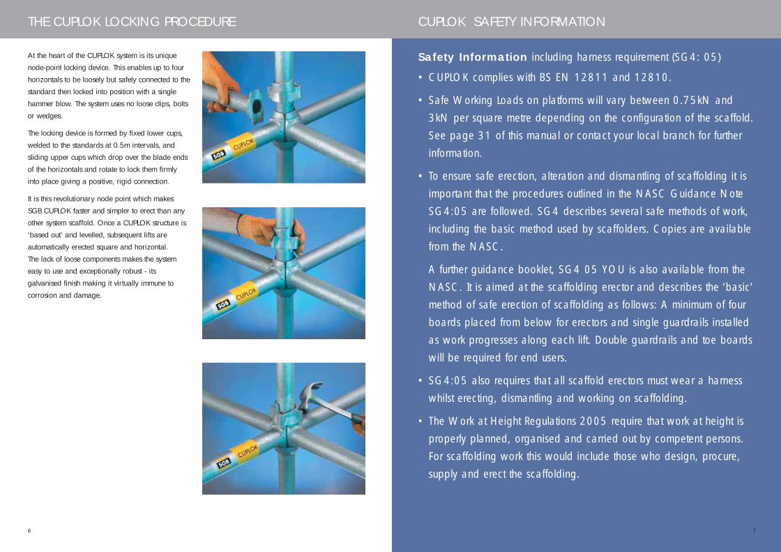
At the heart of the CUPLOK system is its unique
node-point locking device. This enables up to four
horizontals to be loosely but safely connected to the
standard then locked into position with a single
hammer blow. The system uses no loose clips, bolts
or wedges.
The locking device is formed by fixed lower cups,
welded to the standards at 0.5m intervals, and
sliding upper cups which drop over the blade ends
of the horizontals and rotate to lock them firmly
into place giving a positive, rigid connection.
It is this revolutionary node point which makes
SGB CUPLOK faster and simpler to erect than any
other system scaffold. Once a CUPLOK structure is
‘based out’ and levelled, subsequent lifts are
automatically erected square and horizontal.
The lack of loose components makes the system
easy to use and exceptionally robust - its
galvanised finish making it virtually immune to
corrosion and damage.
CUPLOK SAFETY INFORMATION
Safety Information including harness requirement (SG4: 05)
• CUPLOK complies with BS EN 12811 and 12810.
• Safe Working Loads on platforms will vary between 0.75kN and 3kN per square metre depending on the configuration of the scaffold. See page 31 of this manual or contact your local branch for further information.
• To ensure safe erection, alteration and dismantling of scaffolding it is important that the procedures outlined in the NASC Guidance Note SG4:05 are followed. SG4 describes several safe methods of work, including the basic method used by scaffolders. Copies are available from the NASC.
A further guidance booklet, SG4 05 YOU is also available from the NASC. It is aimed at the scaffolding erector and describes the ‘basic’method of safe erection of scaffolding as follows: A minimum of four boards placed from below for erectors and single guardrails installed as work progresses along each lift. Double guardrails and toe boardswill be required for end users.
• SG4:05 also requires that all scaffold erectors must wear a harness whilst erecting, dismantling and working on scaffolding.
• The Work at Height Regulations 2005 require that work at height is properly planned, organised and carried out by competent persons. For scaffolding work this would include those who design, procure, supply and erect the scaffolding.
445.33 CUPLOK USER'S MANUAL_12 12/6/06 11:34 AM Page 6

98
CUPLOK SAFETY INFORMATION GENERAL SITE SAFETY
• All working platforms from where a person could
fall must be fitted with a double guardrail and
toeboards.
• Do not overload the platform with bricks or other
material. If materials are to be placed on the
platform, load all heavy items as close to
standards as possible and use brick-guard panels
to prevent any possibility of materials falling.
If you need to stack large quantities of materials
at platform level, use a CUPLOK Loading Tower.
See page 47.
• All scaffolds require adequate bracing and tying
in. No ties should ever be removed without
adequate supervision. If necessary alternative ties
or bracing should be added first to ensure the
continued safety of the scaffold.
SGB CUPLOK has been designed from the outset
to provide safety to scaffolders and users during
erection, use and dismantling. No loose fittings
are required, lower cups prevent the accidental
dislodging of the ledgers, and guardrails are
automatically positioned at the appropriate
heights for the working platforms. However, the
safety of the scaffold depends both on the
people who erect it and that the scaffolding
structure is not interfered with during use.
Equipment checks following fall incidents
Should any SGB CUPLOK equipment be damaged
in any way as the result of a fall from a scaffold
involving a harness, those components must be
taken out of service and inspected by a competent
person.
For your own safety and that of all thoseworking on the scaffold it is importantthat the following rules are obeyed:
• If the scaffold is on rough or uneven ground,
ensure that it is erected on adequate timber sole
plates - properly bedded and levelled.
• Make sure that the work platform contains no trip
hazards or projections.
• If ladders are used for access, ensure that they
stand on a firm base, and are securely fixed at or
near the top. Also ensure that there is a safe
handhold for getting on and off the working
platform. On many occasions, staircases provide
safe and convenient access for men and
materials. See page 51.
445.33 CUPLOK USER'S MANUAL_12 12/6/06 11:34 AM Page 8
11
CORE COMPONENTS
One of the key strengths of the CUPLOKsystem is the simplicity of the componentrange. Basic horizontals and verticalsform the core of all structures. However,with the addition of a small number ofspecial components, complex scaffoldscan be constructed which safely address awkward access requirements.
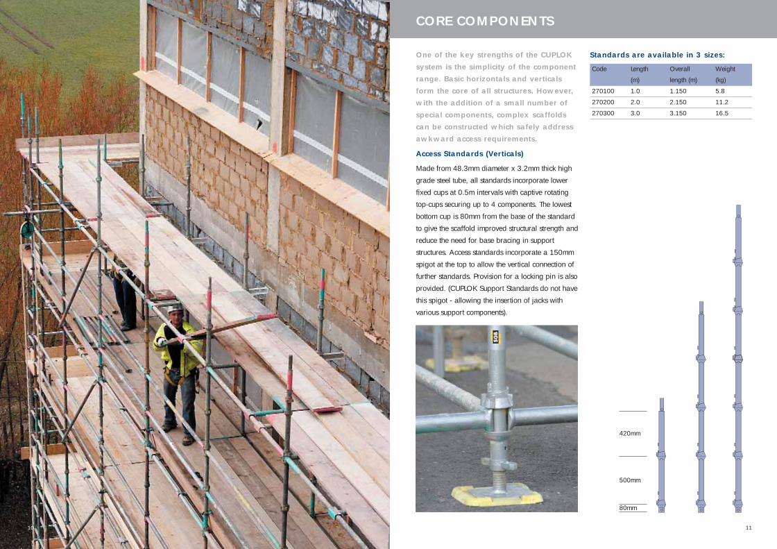
Access Standards (Verticals)
Made from 48.3mm diameter x 3.2mm thick high
grade steel tube, all standards incorporate lower
fixed cups at 0.5m intervals with captive rotating
top-cups securing up to 4 components. The lowest
bottom cup is 80mm from the base of the standard
to give the scaffold improved structural strength and
reduce the need for base bracing in support
structures. Access standards incorporate a 150mm
spigot at the top to allow the vertical connection of
further standards. Provision for a locking pin is also
provided. (CUPLOK Support Standards do not have
this spigot - allowing the insertion of jacks with
various support components).
Standards are available in 3 sizes:
Code Length Overall Weight
(m) length (m) (kg)
270100 1.0 1.150 5.8
270200 2.0 2.150 11.2
270300 3.0 3.150 16.5
420mm
500mm
80mm
10
445.33 CUPLOK USER'S MANUAL_12 12/6/06 11:34 AM Page 10
1312
CUPLOK SCAFFOLD SYSTEM COMPONENTS
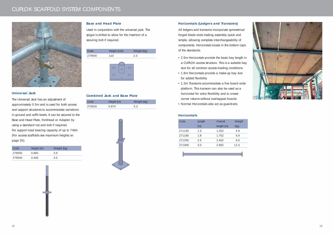
Universal Jack
The Universal Jack has an adjustment of
approximately 0.5m and is used for both access
and support structures to accommodate variations
in ground and soffit levels. It can be secured to the
Base and Head Plate, Forkhead or Adaptor by
using a standard nut and bolt if required.
For support load bearing capacity of up to 74kN
(For access scaffolds see maximum heights on
page 35).
Base and Head Plate
Used in conjunction with the universal jack. The
spigot is drilled to allow for the insertion of a
securing bolt if required.
Code Height (m) Weight (kg)
279550 0.860 3.9
279540 0.400 3.0
Combined Jack and Base Plate
Code Height (m) Weight (kg)
279555 0.870 5.3
Code Height (mm) Weight (kg)
279500 110 2.3
Horizontals (Ledgers and Transoms)
All ledgers and transoms incorporate symmetrical
forged blade ends making assembly quick and
simple, allowing complete interchangeability of
components. Horizontals locate in the bottom cups
of the standards.
• 2.5m Horizontals provide the basic bay length in
a CUPLOK access structure. This is a suitable bay
size for all common access loading conditions.
• 1.8m Horizontals provide a make-up bay size
for added flexibility
• 1.3m Transoms accommodate a five board wide
platform. This transom can also be used as a
horizontal for extra flexibility and to create
corner returns without overlapped boards
• Normal Horizontals also act as guardrails.
Horizontals
Code Length Overall Weight
(m) length (m) (kg)
271130 1.3 1.252 4.9
271180 1.8 1.752 6.9
271250 2.5 2.452 9.5
271300 3.0 2.952 11.5
445.33 CUPLOK USER'S MANUAL_12 12/6/06 11:34 AM Page 12
1514
CUPLOK SCAFFOLD SYSTEM COMPONENTS
Inside Board Transom: 1 and 2 Board
Drop into place over the ledgers and are secured
with a locking device to prevent movement. Act as
conventional transoms but extend beyond the inside
ledger to provide intermediate support to one or
two inside boards.
Description Code Overall Weight
length (m) (kg)
1-Board 273101 1.62 9.0
2-Board 273200 1.895 11.5
Locking device
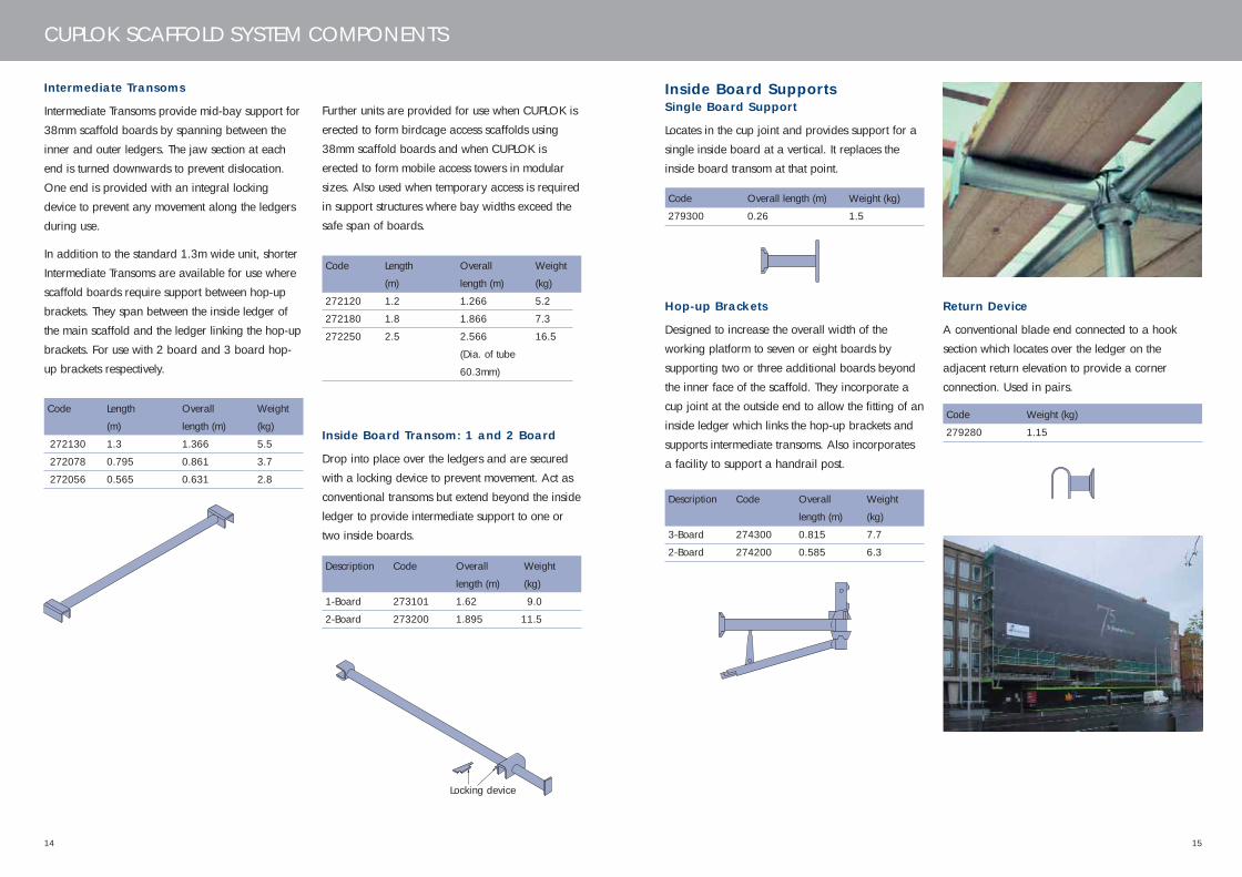
Intermediate Transoms
Intermediate Transoms provide mid-bay support for
38mm scaffold boards by spanning between the
inner and outer ledgers. The jaw section at each
end is turned downwards to prevent dislocation.
One end is provided with an integral locking
device to prevent any movement along the ledgers
during use.
In addition to the standard 1.3m wide unit, shorter
Intermediate Transoms are available for use where
scaffold boards require support between hop-up
brackets. They span between the inside ledger of
the main scaffold and the ledger linking the hop-up
brackets. For use with 2 board and 3 board hop-
up brackets respectively.
Code Length Overall Weight
(m) length (m) (kg)
272130 1.3 1.366 5.5
272078 0.795 0.861 3.7
272056 0.565 0.631 2.8
Code Length Overall Weight
(m) length (m) (kg)
272120 1.2 1.266 5.2
272180 1.8 1.866 7.3
272250 2.5 2.566 16.5
(Dia. of tube
60.3mm)
Further units are provided for use when CUPLOK is
erected to form birdcage access scaffolds using
38mm scaffold boards and when CUPLOK is
erected to form mobile access towers in modular
sizes. Also used when temporary access is required
in support structures where bay widths exceed the
safe span of boards.
Code Overall length (m) Weight (kg)
279300 0.26 1.5
Code Weight (kg)
279280 1.15
Inside Board SupportsSingle Board Support
Locates in the cup joint and provides support for a
single inside board at a vertical. It replaces the
inside board transom at that point.
Return Device
A conventional blade end connected to a hook
section which locates over the ledger on the
adjacent return elevation to provide a corner
connection. Used in pairs.
Hop-up Brackets
Designed to increase the overall width of the
working platform to seven or eight boards by
supporting two or three additional boards beyond
the inner face of the scaffold. They incorporate a
cup joint at the outside end to allow the fitting of an
inside ledger which links the hop-up brackets and
supports intermediate transoms. Also incorporates
a facility to support a handrail post.
Description Code Overall Weight
length (m) (kg)
3-Board 274300 0.815 7.7
2-Board 274200 0.585 6.3
445.33 CUPLOK USER'S MANUAL_12 12/6/06 11:34 AM Page 14

1716
CUPLOK SCAFFOLD SYSTEM COMPONENTS
CUPLOK SCAFFOLD SYSTEM COMPONENTS
Scaffold Boards
• A variety of lengths are available
• British Standard: Support frequency every 1.5m
• MSG: Support frequency every 1.2m
Please contact your local branch for details.
Handrail Post
For use with Hop-up Brackets, staircase towers
and on support scaffolds if required. Incorporates
cup joints to allow the location of ledgers to form
guard rails.
Code Overall length (m) Weight (kg)
279244 1.150 4.8
Code Length (m) Weight (kg)
274541 1.3 9.85
274852 1.6 12.12
274543 1.8 13.64
274544 2.5 18.59
274545 3.0 22.31
Hook-end Batten (not available in the UK)
A durable steel deck unit with punched profile.
Steel tubes underneath add extra strength.
Castor Wheels
For use when CUPLOK is erected as a mobile
tower. The shank of the wheel fits into the base of
the CUPLOK standard and is secured with a
hexagonal head bolt.
Safe Working Loads:
Steel castor wheel 730kg
Rubber tyred castor wheel 270kg
Description Code Weight Diameter
(kg) (mm)
Steel 279100 7.0 200
Rubber 279080 6.7 200
Spigot Pin
Designed to resist minor tensile forces at the joint of
two standards - though not designed to form a full
tension joint. Must be used where hop-up brackets
are incorporated in the scaffold and on loading
towers.
Code Weight (kg) Diameter (mm)
279340 0.09 8.0
ANCILLARY COMPONENTS
Access Ledger Brace
Provides ledger-bracing on CUPLOK access
scaffolds. When ties cannot be placed in the
correct position or have been removed, or on
scaffolds which extend above the building.
Incorporates fixed wedge half couplers which
locate on the standards.
Description Code Weight Overall
(kg) length (m)
1.5 x 1.3m 277531 9.3 1.750
2.0 x 1.3m 277551 10.7 2.100
Wedge halfcoupler (fixed)
Swivel Face Brace
Provides face bracing on a CUPLOK access
scaffold. Each brace has swivelling blade ends to
allow for easy location within the node joint. As
only one blade end can be located in each joint,
parallel bracing is employed rather than the ‘dog-
leg’ or ‘zig-zag’ method.
Description Code Weight Overall
(kg) length (m)
1.8 x 1.5m 276150 8.7 2.396
1.8 x 2.0m 276180 9.8 2.744
2.5 x 1.5m 276153 10.7 2.969
2.5 x 2.0m 276203 11.5 3.255
3.0 x 2.0m 276207 13.0 3.660
L
X
Y
Swivel blade
Brace Adaptor With Half Coupler (not available in the UK)
A half coupler with a CUPLOK blade end which
allows the use of tubular scaffolding as a bracing
component.
Code Weight (kg)
279163 1.0
445.33 CUPLOK USER'S MANUAL_12 12/6/06 11:34 AM Page 16
18
ANCILLARY COMPONENTS
19
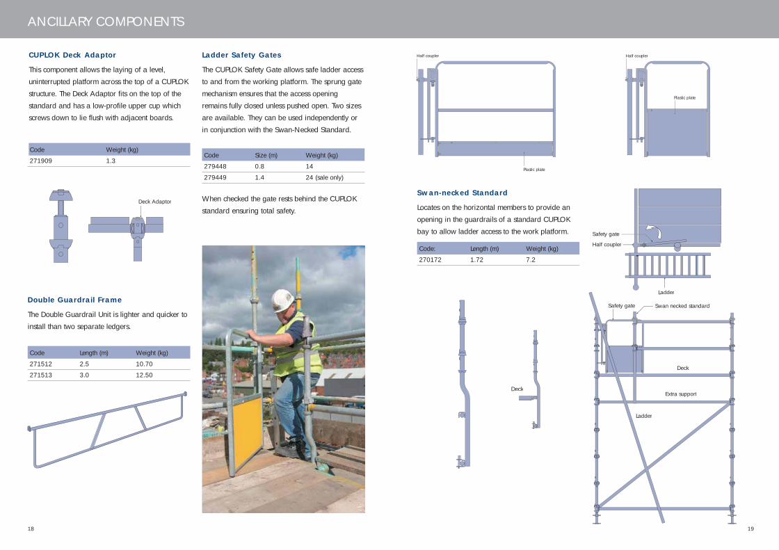
Double Guardrail Frame
The Double Guardrail Unit is lighter and quicker to
install than two separate ledgers.
Code Length (m) Weight (kg)
271512 2.5 10.70
271513 3.0 12.50
Deck Adaptor
Code Weight (kg)
271909 1.3
CUPLOK Deck Adaptor
This component allows the laying of a level,
uninterrupted platform across the top of a CUPLOK
structure. The Deck Adaptor fits on the top of the
standard and has a low-profile upper cup which
screws down to lie flush with adjacent boards.
Code Size (m) Weight (kg)
279448 0.8 14
279449 1.4 24 (sale only)
Ladder Safety Gates
The CUPLOK Safety Gate allows safe ladder access
to and from the working platform. The sprung gate
mechanism ensures that the access opening
remains fully closed unless pushed open. Two sizes
are available. They can be used independently or
in conjunction with the Swan-Necked Standard.
Plastic plate
Half coupler
Plastic plate
Half coupler
When checked the gate rests behind the CUPLOK
standard ensuring total safety.
Deck
Swan-necked Standard
Locates on the horizontal members to provide an
opening in the guardrails of a standard CUPLOK
bay to allow ladder access to the work platform.
Code: Length (m) Weight (kg)
270172 1.72 7.2
Ladder
Half coupler
Safety gate
Deck
Extra support
Swan necked standard
Ladder
Safety gate
445.33 CUPLOK USER'S MANUAL_12 12/6/06 11:34 AM Page 18
21
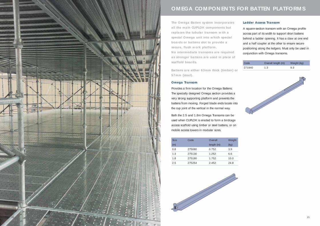
The Omega Batten system incorporatesall the main CUPLOK components butreplaces the tubular transom with aspecial Omega unit into which specialboards or battens slot to provide asecure, flush work platform. No intermediate transoms are requiredas stronger battens are used in place ofscaffold boards.
Battens are either 63mm thick (timber) or57mm (steel).
Omega Transom
Provides a firm location for the Omega Battens.
The specially designed Omega section provides a
very strong supporting platform and prevents the
battens from moving. Forged blade ends locate into
the cup joint of the vertical in the normal way.
Both the 2.5 and 1.8m Omega Transoms can be
used when CUPLOK is erected to form a birdcage
access scaffold using timber or steel battens, or on
mobile access towers in modular sizes.
Size Code Overall Weight
(m) length (m) (kg)
0.8 275080 0.752 3.9
1.3 275130 1.252 6.6
1.8 275180 1.752 10.0
2.5 275254 2.452 24.8
Ladder Access Transom
A square-section transom with an Omega profile
across part of its width to support short battens
behind a ladder opening. It has a claw at one end
and a half coupler at the other to ensure secure
positioning along the ledgers. Must only be used in
conjunction with Omega transoms.
Code Overall length (m) Weight (kg)
271940 1.3 9.3
OMEGA COMPONENTS FOR BATTEN PLATFORMS
20
445.33 CUPLOK USER'S MANUAL_12 12/6/06 11:34 AM Page 20

2322
OMEGA COMPONENTS FOR BATTEN PLATFORMS
Return Transom
A transom with a steel hook profile which locates
over the ledger of the adjacent return scaffold,
linking the two sections together. The other side of
the transom incorporates a conventional Omega
section to receive timber or steel battens.
Code Length (m) Weight (kg)
275550 1.3 8.6
Description Code Length (m) Weight (kg)
2-Board 279120 6.6
3-Board 275533 9.3
Omega Single Board Support
Locates at the cup joint and provides support for a
single inside batten.
Code Overall length (m) Weight (kg)
275510 0.267 2.3
Omega Hop-up Bracket
Designed to increase the overall width of the
working platform to seven or eight Battens by
supporting two or three additional battens beyond
the inner face of the scaffold. It incorporates a cup
joint at the far end to allow the fitting of an inside
ledger which links the hop-up brackets to prevent
movement. It also incorporates an opening to
support a handrail post.
Description Code Overall Weight
length (m) (kg)
3-Board 275530 0.815 7.6
2-Board 275520 0.585 6.6
Timber Battens
63mm thick and of 225mm nominal width. Weights
shown are approximate at 20% moisture content.
Description Code Weight Overall
(kg) length (m)
1.3m 274613 9.5 1.250
1.8m 274617 13.0 1.750
2.5m 274625 18.0 2.450
Steel Battens
CUPLOK Galvanised Steel Battens are 57mm thick
and 238mm wide. They incorporate a non-skid
perforated surface for slip resistance in poor
weather.
Description Code Weight Overall
(kg) length (m)
1.3m 274512 8.4 1.250
1.8m 274517 13.0 1.750
2.5m 274525 17.5 2.450
Toeboard Clips
Timber
For use with timber battens only. Locates around the
standards and sits on the 'top-hat' section of the
Omega transom
Code Weight (kg) Size (mm)
279200 1.0 150 x 120 x 171
Steel
For use with steel battens only. Locates around the
standards and locks the toeboard rigidly into
position
Code Weight (kg)
279180 1.0
Code Weight (kg)
275585 1.5
End Toeboard Clip
Locates on the Omega Transom. For use with
timber or steel battens.
Omega Two and Three Board Corner Units
Provides an external corner support 2 or 3 battens
wide. For use between hop-up brackets. Infill with
timber, cut to fit.
445.33 CUPLOK USER'S MANUAL_12 12/6/06 11:34 AM Page 22
2524
TYPICAL TUBULAR CUPLOK ACCESS LAYOUTS
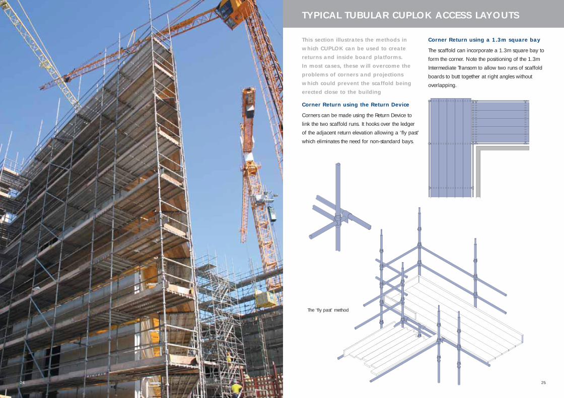
This section illustrates the methods inwhich CUPLOK can be used to createreturns and inside board platforms. In most cases, these will overcome theproblems of corners and projectionswhich could prevent the scaffold beingerected close to the building
Corner Return using the Return Device
Corners can be made using the Return Device to
link the two scaffold runs. It hooks over the ledger
of the adjacent return elevation allowing a ‘fly past’
which eliminates the need for non-standard bays.
The ‘fly past’ method
Corner Return using a 1.3m square bay
The scaffold can incorporate a 1.3m square bay to
form the corner. Note the positioning of the 1.3m
Intermediate Transom to allow two runs of scaffold
boards to butt together at right angles without
overlapping.
445.33 CUPLOK USER'S MANUAL_12 12/6/06 11:34 AM Page 24

2726
TYPICAL TUBULAR CUPLOK ACCESS LAYOUTS
Inside Platforms: One Board
External Corners
Single Inside Board Platforms on CUPLOK Tubular
Scaffolds are constructed using the Single Board
Support in conjunction with the Inside Board
Transom. Either the 1.3m square bay or the
standard method using the Return Device can be
used. Note the positioning of the inside board
transom to allow boards to butt together without
overlapping.
1.3m square bay
Using Return Devices
Internal Corners
The addition of an extra single board support at
the corner standard ensures maximum safety when
the 2 inside scaffold boards butt together at 90°.
An Inside Board Transom must also be used
adjacent to the corner standard, as shown.
Inside Platforms: Two and Three Board
Two and three board Inside Platforms are
constructed using the appropriate sized Hop-up
Brackets. These are linked together with Ledgers to
allow the location of the 2 or 3 Board Intermediate
Transom which supports the scaffold boards at the
required centres. On internal corners, end
guardrails above the Hop-up Brackets can be
formed using small butts of tube and Double
Couplers.
Internal Corners
External Corners
1300 1300
1300
Note
Where required, the small gap between the main
and inside platforms can be covered using suitable
plywood strips fixed into position.
445.33 CUPLOK USER'S MANUAL_12 12/6/06 11:34 AM Page 26

28
TYPICAL OMEGA ACCESS LAYOUTS
29
Corner returns
Corner returns using the Omega Batten System can
be formed either by using the Omega Return
Transom - which locates over the ledger of the
adjacent return elevation, or by using a 1.3m
square bay in the corner which is constructed using
1.3m Omega Transoms on three sides.
Inside Platforms: 1 Board
External CornersInside board platforms are constructed using the
Omega Single Board Support. When constructing
the scaffold with the 1.3m square corner bay, note
the extra Omega Transom used to accept the inside
batten from the return elevation, and the use of the
return transom to eliminate the gap when using
timber or steel battens. A loose batten is required to
cover the remaining gap in the inside board run.
Internal Corners
Note the use of the Omega Transoms on all 4 sides
of the corner bay.
Inside Platforms: 2 and 3 Board
External Corners
Both elevations of scaffolding incorporate a 1.3m
square bay at the end which share two common
standards. Note the use of the extra Omega
Transom in one elevation to receive the inside
battens from the return elevation. Two loose battens
are required to cover the remaining gap in the
inside board run.
Using harnesses with the SGB CUPLOKOmega Batten System
The Omega system varies from traditional boarded
structures by allowing the decking to span directly
from one transom to the next without needing
intermediate support. Omega scaffold structures
therefore do not always employ tubular ledgers at
platform level. Tubular guardrails are installed in
the usual manner.
In this application we would recommend the
installation of both ledgers at platform level in
order to provide the attachment point for a lanyard
as described above. If this procedure is followed,
then the guidance above can be applied - unless
attachment to the transom is not practicable due to
its shape.
Internal Corners
The 1.3m square corner bay is constructed with
Omega Transoms on all 4 sides. The Omega
Corner Piece (2 or 3 board) is used with cut down
timber battens.
445.33 CUPLOK USER'S MANUAL_12 12/6/06 11:34 AM Page 28

31
SAFE WORKING LOADS FOR TUBULAR COMPONENTS
Safe Working Loads for CUPLOK TubularComponents
Component UDL Load Central Point Third points
(m) (kN) Load (kN) (2 off) (kN)
1.3 Transom 8.0 4.5 7.5
1.8 ledger 6.37 3.2 4.76
2.5 ledger 6.37 3.2 4.76
Hop-up Brackets (2 and 3 Board)
Intermediate Transoms
Length L Safe Uniformly
(mm) Distributed Load (kN)
565 8.5
795 7.1
1200 5.1
1300 4.4
1800 3.6
2500 5.0
L
1 Board Inside Board Transom and1 Board Support
Safe Working Loads uniformly distributed 0.9kN.
These components permit a deck loading of
3.0kN/m2 when bays are 2.5m long.
4.38kN 0.9kN
3.2kN1 Board Inside Transom
0.9kN
1 Board Support
Bracket Suitable for deck loading of
2 Board 1.5kN/m2
3 Board 0.75kN/m2
This section gives information on safeworking loads, tying arrangements and maximum heights for scaffolds. These values have been thoroughlytested and researched and shouldalways be followed. If you are in anydoubt about the design of a CUPLOKstructure, contact your SGB Branch.
30
445.33 CUPLOK USER'S MANUAL_12 12/6/06 11:34 AM Page 30

3332
SAFE WORKING LOADS FOR OMEGA COMPONENTS SCAFFOLD OPENINGS
Safe Working Loads for CUPLOK OmegaComponents
1.3m Omega Transom
SWL uniformly distributed = 10.38kN
Equivalent to a deck loading of 3.0kN/m2 on a
2.5m bay.
1.8m Omega Transom
SWL uniformly distributed = 7.5kN
2.5m Omega Transom(heavy duty type)
SWL uniformly distributed = 11.75kN (1.5kN/m2)
2.5m Omega Transom(light duty type) - obsolete component
SWL uniformly distributed = 5.40kN (0.75kN/m2)
.
Omega Hop-Up Brackets (2 and 3 Board)
Bracket Suitable
for Deck
Loading of
2 Board 1.5kN/m2
3 Board 0.75kN/m2
Omega One Board Support
W = 2.0kN - suitable for deck loading of
3.0kN/m2 on a 2.5m bay.
Vehicle openings
To create a two-bay wide opening in a CUPLOK
structure for vehicle or other access the following
procedure may be adopted.
• Build the scaffold in the normal manner
• Plan-brace the structure above the desired
opening level and place face bracing on the
inner and outer face as shown below
• Remove the structure below the spanning level
The remainder of the structure can then be erected
as shown using standard diagonal bracing.
Inner brace
Outer brace
For larger openings, Bridging Ledgers or SGB
COVERSPAN 400 beams should be used to
provide a spanning member from which to build
the upper section of the scaffold.
445.33 CUPLOK USER'S MANUAL_12 12/6/06 11:34 AM Page 32

3534
BRACING AND TYING IN MAXIMUM HEIGHTS - CUPLOK ACCESS
Bracing and Tying In
All scaffolds require diagonal face bracing to
prevent the structure distorting or swaying.
Face Bracing is required in all CUPLOK access
structures in one bay per 20m run (i.e. every eighth
bay) for the full height of the scaffold.
For a scaffold more than 10m (4 bays) long, a
minimum of two bays should be face-braced.
Bracing the end bays should be avoided if possible.
Ledger and Plan Bracing
CUPLOK Access structures do not generally require
ledger or plan bracing. Exceptions occur where:
• Ties cannot be placed in the correct position
• Where ties have to be removed
• If scaffold structures extend above the building
The maximum height to which a CUPLOK Access
Scaffold may be erected is dependent upon a
number of factors, the most important of which are:
1. The vertical distance between tied points on
a standard.
2. Whether or not foot ties are used - see bracing
rules below.
3. The lift height.
4. Wind loading.
5. Whether or not cantilever platforms are used.
6. Number of boarded lifts*.
*Note - where lifts are not boarded it has been
assumed the the boards, toe-boards and the
Hop-up brackets (where applicable) have been
removed but the intermediate transoms have been
left in place. In order to comply with safety
regulations one continuous ledger must be left
to form a single guard-rail along the front of the
scaffold and across the ends.
The parameters detailed in this manual are based
on calculations and the result of extensive testing.
These calculations do not apply to sheeted or netted
CUPLOK structures, for which the rules relating to
bracing, tying-in and load carrying capacity differ.
Bracing and Tying rules
1. To use the data in the following load tables the
following rules apply:
Foot Ties
• For 2m lift heights plan bracing is required at a
frequency of one bay in eight. Plan bracing should
be placed in the face-braced bays. See figure F on
page 41. However, for platform heights up to 14m,
fully boarded, plan bracing can be omitted.
• For 1.5m lift heights no plan bracing is required.
No Foot Ties
• For 2m lift heights plan bracing is required as
well as ledger bracing on all standards in the first
lift. See figure G on page 41.
• For 1.5m lift heights no additional bracing is
required.
2. Face bracing must be used at a frequency of one
bay in every eight. A minimum of two bays must
be braced for scaffolds greater than four bays in
length.
3. For both 1.5m and 2.0m lift scaffolds, one
working lift up to 2 lifts above the last tied level is
permitted, but these 2 lifts must be ledger braced.
4. For 2m lift heights, whatever tie pattern is used
i.e. 8m, 6m or 4m, the standards at both ends of
the tied level must be tied to the supporting
structure (refer to the pattern diagrams on pages
40 to 41).
5. Ties must be attached to both insideand outside standards (or ledgers) usingClass B Right Angled Couplers. Where itis not possible to do this ‘V-Ties’ must beused at a frequency of one in five baysfor every level of ties. See Figure F on page 41.
For further information, please contact your local
SGB Branch.
445.33 CUPLOK USER'S MANUAL_12 12/6/06 11:34 AM Page 34

3736
MAXIMUM HEIGHTS - CUPLOK ACCESS
Platform loadings - working lifts
For scaffolds with more than 1 boarded lift, the
following loading has been considered for both
2m lift and 1.5 lift structures:
1 working platform @ 3kN/m2 and
1 working platform @ 1.5kN/m2.
For 1.5m Lift (bricklayer’s) scaffolds only, data is
given for 1 working platform at 3kN/m2.
Where hop-up brackets are used the loading for
both the main platform and the hop-up bracket is
as follows:
1 Board 3kN/m2
2 Board 1.5kN/m2
3 Board 0.75kN/m2
The use of Hop-Up Brackets
The following rules must be applied when either
standard board or Omega batten Hop-up Brackets
are present:
1. If used as a separate working platform between
lifts, then a 3 board Hop-Up Bracket must be
used.
2. Only one loaded Hop-Up Bracket is permitted
between levels at any time.
3. Spigot pins must be used at all joints in the
standards down to the last tied level below the
Hop-Up Bracket.
Wind loading
For 2m Lift (access scaffolds) three maximum wind
pressures have been considered:
Case I - 685N/m2
Case II - 475N/m2
Case III - 355N/m2
For 1.5m Lift (bricklayer’s scaffolds) lift heights are
given for the maximum wind of 685N/m2 and no
wind loading.
For less onerous cases it may be possible to omit
ledger bracing and/or increase the permissible
height of the scaffold. For specific cases, please
contact your local SGB Branch.
2m Lifts - 4m Tie Pattern (with plan bracing)
Number of Number Live load Hop-up Maximum number of lifts
Boarded Lifts* of lifts applied Brackets Foot Tie No Foot tie
loaded (kN/m2)
Case I - Case II - Case III - Case I - Case II - Case III -
685N 475N 355N 685N 475N 355N
2 1.5 3.00 None 43 43 43 36 36 36
Fully Boarded 1.5 3.00 None 18 18 18 15 15 15
2 1.5 3.00 1 Board 36 36 36 34 34 34
Fully Boarded 1.5 3.00 1 Board 15 15 15 14 14 14
2 1.5 1.50 2 Board 41 41 41 41 41 41
Fully Boarded 1.5 1.50 2 Board 18 18 18 18 18 18
2 1.5 0.75 3 Board 43 43 45 48 48 48
Fully Boarded 1.5 0.75 3 Board 18 18 19 20 20 20
2m Lifts - 6m Tie Pattern (with plan bracing)
Number of Number Live load Hop-up Maximum number of lifts
Boarded Lifts* of lifts applied Brackets Foot Tie No Foot tie
loaded (kN/m2)
Case I - Case II - Case III - Case I - Case II - Case III -
685N 475N 355N 685N 475N 355N
2 1.5 3.00 None 25 25 25 25 25 25
Fully Boarded 1.5 3.00 None 11 11 11 11 11 11
2 1.5 3.00 1 Board 23 23 23 21 21 21
Fully Boarded 1.5 3.00 1 Board 10 10 10 9 9 9
2 1.5 1.50 2 Board 26 26 26 24 26 26
Fully Boarded 1.5 1.50 2 Board 11 13 13 10 11 11
2 1.5 0.75 3 Board 28 28 28 26 30 30
Fully Boarded 1.5 0.75 3 Board 12 14 14 11 13 13
*Unboarded lifts with single guardrail
Maximum heights
445.33 CUPLOK USER'S MANUAL_12 12/6/06 11:34 AM Page 36
38
MAXIMUM HEIGHTS - CUPLOK ACCESS
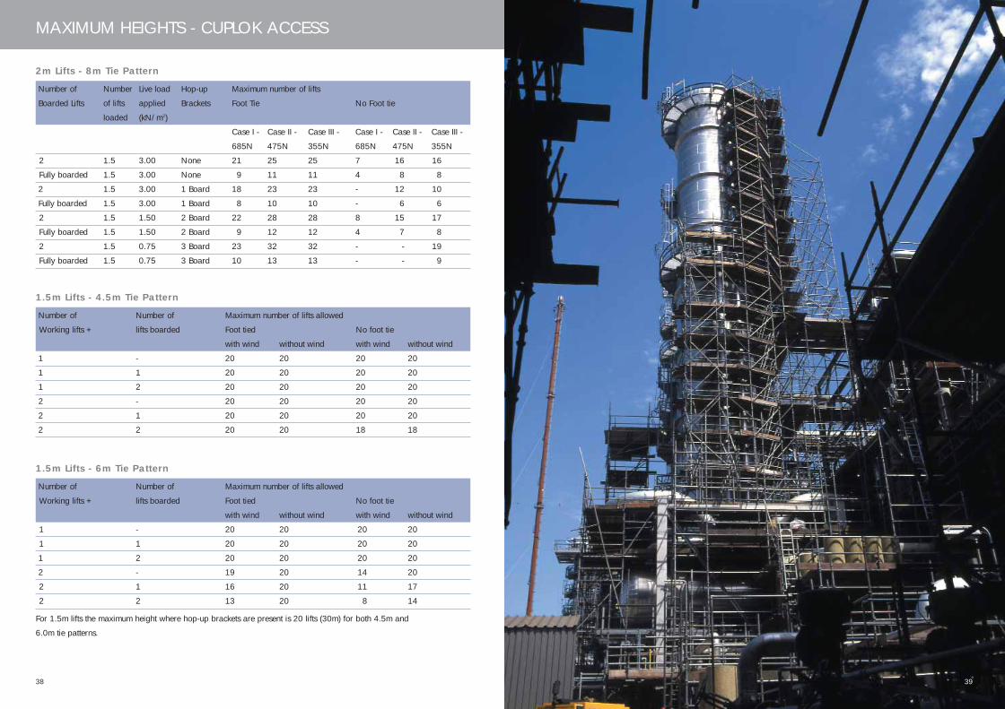
1.5m Lifts - 4.5m Tie Pattern
Number of Number of Maximum number of lifts allowed
Working lifts + lifts boarded Foot tied No foot tie
with wind without wind with wind without wind
1 - 20 20 20 20
1 1 20 20 20 20
1 2 20 20 20 20
2 - 20 20 20 20
2 1 20 20 20 20
2 2 20 20 18 18
1.5m Lifts - 6m Tie Pattern
Number of Number of Maximum number of lifts allowed
Working lifts + lifts boarded Foot tied No foot tie
with wind without wind with wind without wind
1 - 20 20 20 20
1 1 20 20 20 20
1 2 20 20 20 20
2 - 19 20 14 20
2 1 16 20 11 17
2 2 13 20 8 14
For 1.5m lifts the maximum height where hop-up brackets are present is 20 lifts (30m) for both 4.5m and
6.0m tie patterns.
2m Lifts - 8m Tie Pattern
Number of Number Live load Hop-up Maximum number of lifts
Boarded Lifts of lifts applied Brackets Foot Tie No Foot tie
loaded (kN/m2)
Case I - Case II - Case III - Case I - Case II - Case III -
685N 475N 355N 685N 475N 355N
2 1.5 3.00 None 21 25 25 7 16 16
Fully boarded 1.5 3.00 None 9 11 11 4 8 8
2 1.5 3.00 1 Board 18 23 23 - 12 10
Fully boarded 1.5 3.00 1 Board 8 10 10 - 6 6
2 1.5 1.50 2 Board 22 28 28 8 15 17
Fully boarded 1.5 1.50 2 Board 9 12 12 4 7 8
2 1.5 0.75 3 Board 23 32 32 - - 19
Fully boarded 1.5 0.75 3 Board 10 13 13 - - 9
39
445.33 CUPLOK USER'S MANUAL_12 12/6/06 11:34 AM Page 38

4140
SAFE WORKING LOADS
E. 1.5m Lifts - 6m Tie Pattern
Horizontal spacing - every standard
Vertical spacing - maximum 6.0m
See note for tie pattern A but
Horizontal 7.5m Vertical 9.0m
Typical Tie Patterns
A. 2m Lifts - 8m Tie Pattern
Horizontal spacing - every standard
Vertical spacing - maximum 8.0m
If ties cannot be positioned in the correct place or
have to be moved, then bracing has to be used
between adjacent ties. If this is done using plan
bracing, the maximum horizontal distance between
ties is 7.5m. If done using Ledger bracing the
maximum vertical distance between ties is 12m.
B. 2m Lifts - 6m Tie Pattern
Horizontal spacing - every standard
Vertical spacing - maximum 6.0m
See note for tie pattern A but
Horizontal 7.5m Vertical 10.0m
C. 2.0m Lifts - 4m Tie Pattern
Horizontal spacing - every standard
Vertical spacing - maximum 4.0m
8.0m
4.5m
See note for tie pattern A but
Horizontal 7.5m Vertical 8.0m
See note for tie pattern A but
Horizontal 7.5m Vertical 9.0m
4.0m
4.0m
2.5m
1.5m 4.5m
4.5m
1.0m
1.5m6.0m
6.0m
1.0m
2m2m
2.5m
6.0m
6.0m
4.5m
D. 1.5m Lifts - 4.5m Tie Pattern
Horizontal spacing - every standard
Vertical spacing - maximum 4.5m
Bracing arrangements
F. Structures with foot ties - 2.0m lifts with plan and ledger bracing
G. Structures without foot ties - 2.0m lifts with plan and ledger bracing
Plan bracing should be assumed. To remove plan
bracing, please refer to your local branch for safety
information.
Planbrace
Plan brace
Footties
Facebrace
Planbrace
Ledgerbracing
Facebrace
2m2m
0.5m
445.33 CUPLOK USER'S MANUAL_12 12/6/06 11:34 AM Page 40

43
CIRCULAR ACCESS
CUPLOK’s ability to allow ledgers to lockinto the standards from any angle meansthat the system is ideally suited tocurved and circular structures. Withsimple variations to the normalarrangement of ledgers and transoms,both internal and external curves can becreated.
Make-up of a curved scaffold
Curved structures are made up by using a
combination of rectangular and trapezium shaped
bays - depending on the radius of curve required.
Trapezium-shaped bays incorporate inside and
outside ledgers of different length. Intermediate
transoms cannot be used in trapezium sections,
therefore these bays should always be constructed
using short ledgers to remove the need for
additional board support. If larger trapezium bays
are inevitable, thicker boards should be used.
A curved CUPLOK structure can be constructed in
two ways:
Trapezium bayRectangular bay
All trapezium bays
B Using only trapezium shaped bays
Layout of ledgers and transoms
As no two ledgers or transoms can be fitted into the
same cup at less than 90° to each other, on curved
structures the inside ledgers, outside ledgers and
transoms cannot all be situated at the same level.
On external scaffolds it is quite simple to locate the
outside run of ledgers above the deck level to form
the handrails (see diagram). On internal scaffolds,
the most convenient method is to move the inner
ledgers down by 0.5m in alternate bays (see
diagram on page 44).
A Using a combination of rectangularand trapezium shaped bays
42
445.33 CUPLOK USER'S MANUAL_12 12/6/06 11:34 AM Page 42
4544
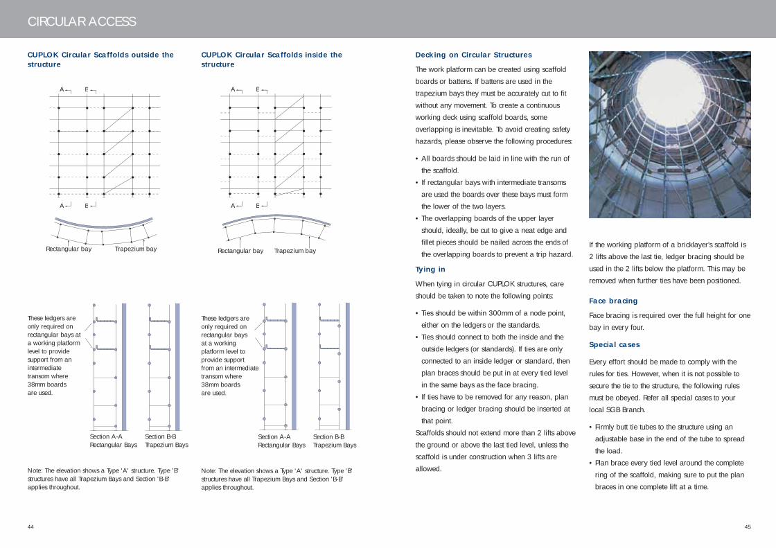
CIRCULAR ACCESS
CUPLOK Circular Scaffolds outside thestructure
These ledgers areonly required onrectangular bays ata working platformlevel to provide support from anintermediatetransom where38mm boards are used.
Section A-ARectangular Bays
Section B-BTrapezium Bays
Note: The elevation shows a Type 'A' structure. Type 'B'structures have all Trapezium Bays and Section 'B-B'applies throughout.
CUPLOK Circular Scaffolds inside thestructure
These ledgers areonly required onrectangular bays at a workingplatform level toprovide supportfrom an intermediatetransom where38mm boards are used.
Section A-ARectangular Bays
Section B-BTrapezium Bays
Note: The elevation shows a Type 'A' structure. Type 'B'structures have all Trapezium Bays and Section 'B-B'applies throughout.
Trapezium bayRectangular bay
A B
A B
Trapezium bayRectangular bay
A B
A B
Decking on Circular Structures
The work platform can be created using scaffold
boards or battens. If battens are used in the
trapezium bays they must be accurately cut to fit
without any movement. To create a continuous
working deck using scaffold boards, some
overlapping is inevitable. To avoid creating safety
hazards, please observe the following procedures:
• All boards should be laid in line with the run of
the scaffold.
• If rectangular bays with intermediate transoms
are used the boards over these bays must form
the lower of the two layers.
• The overlapping boards of the upper layer
should, ideally, be cut to give a neat edge and
fillet pieces should be nailed across the ends of
the overlapping boards to prevent a trip hazard.
Tying in
When tying in circular CUPLOK structures, care
should be taken to note the following points:
• Ties should be within 300mm of a node point,
either on the ledgers or the standards.
• Ties should connect to both the inside and the
outside ledgers (or standards). If ties are only
connected to an inside ledger or standard, then
plan braces should be put in at every tied level
in the same bays as the face bracing.
• If ties have to be removed for any reason, plan
bracing or ledger bracing should be inserted at
that point.
Scaffolds should not extend more than 2 lifts above
the ground or above the last tied level, unless the
scaffold is under construction when 3 lifts are
allowed.
If the working platform of a bricklayer’s scaffold is
2 lifts above the last tie, ledger bracing should be
used in the 2 lifts below the platform. This may be
removed when further ties have been positioned.
Face bracing
Face bracing is required over the full height for one
bay in every four.
Special cases
Every effort should be made to comply with the
rules for ties. However, when it is not possible to
secure the tie to the structure, the following rules
must be obeyed. Refer all special cases to your
local SGB Branch.
• Firmly butt tie tubes to the structure using an
adjustable base in the end of the tube to spread
the load.
• Plan brace every tied level around the complete
ring of the scaffold, making sure to put the plan
braces in one complete lift at a time.
445.33 CUPLOK USER'S MANUAL_12 12/6/06 11:34 AM Page 44
47
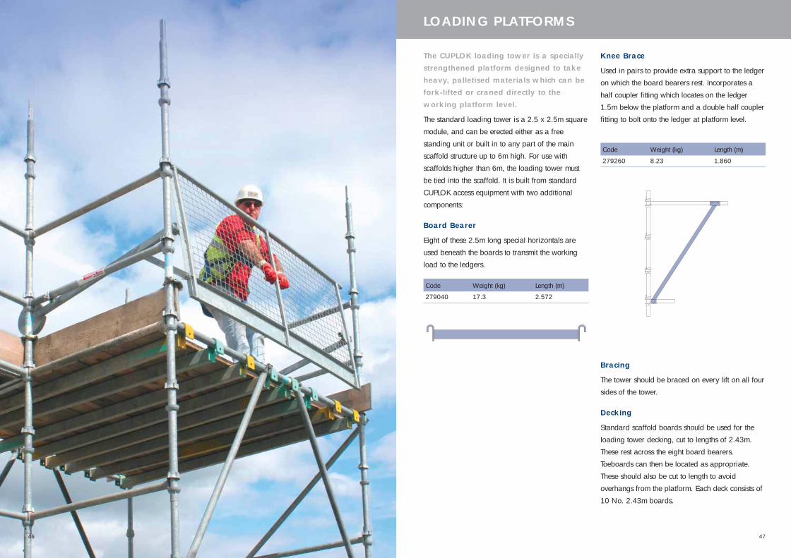
LOADING PLATFORMS
The CUPLOK loading tower is a speciallystrengthened platform designed to takeheavy, palletised materials which can befork-lifted or craned directly to theworking platform level.
The standard loading tower is a 2.5 x 2.5m square
module, and can be erected either as a free
standing unit or built in to any part of the main
scaffold structure up to 6m high. For use with
scaffolds higher than 6m, the loading tower must
be tied into the scaffold. It is built from standard
CUPLOK access equipment with two additional
components:
Board Bearer
Eight of these 2.5m long special horizontals are
used beneath the boards to transmit the working
load to the ledgers.
Code Weight (kg) Length (m)
279040 17.3 2.572
Code Weight (kg) Length (m)
279260 8.23 1.860
Knee Brace
Used in pairs to provide extra support to the ledger
on which the board bearers rest. Incorporates a
half coupler fitting which locates on the ledger
1.5m below the platform and a double half coupler
fitting to bolt onto the ledger at platform level.
Bracing
The tower should be braced on every lift on all four
sides of the tower.
Decking
Standard scaffold boards should be used for the
loading tower decking, cut to lengths of 2.43m.
These rest across the eight board bearers.
Toeboards can then be located as appropriate.
These should also be cut to length to avoid
overhangs from the platform. Each deck consists of
10 No. 2.43m boards.
46
445.33 CUPLOK USER'S MANUAL_12 12/6/06 11:34 AM Page 46
4948
LOADING TOWERS
Lift Make-up
The working platform height dictates the design of the tower structure. Lift increments of 1.0, 1.5 or 2m can
be employed. The top lift must be 1.5m to accommodate the Knee Brace.
The table below shows the lift make-up for a range of platform heights.
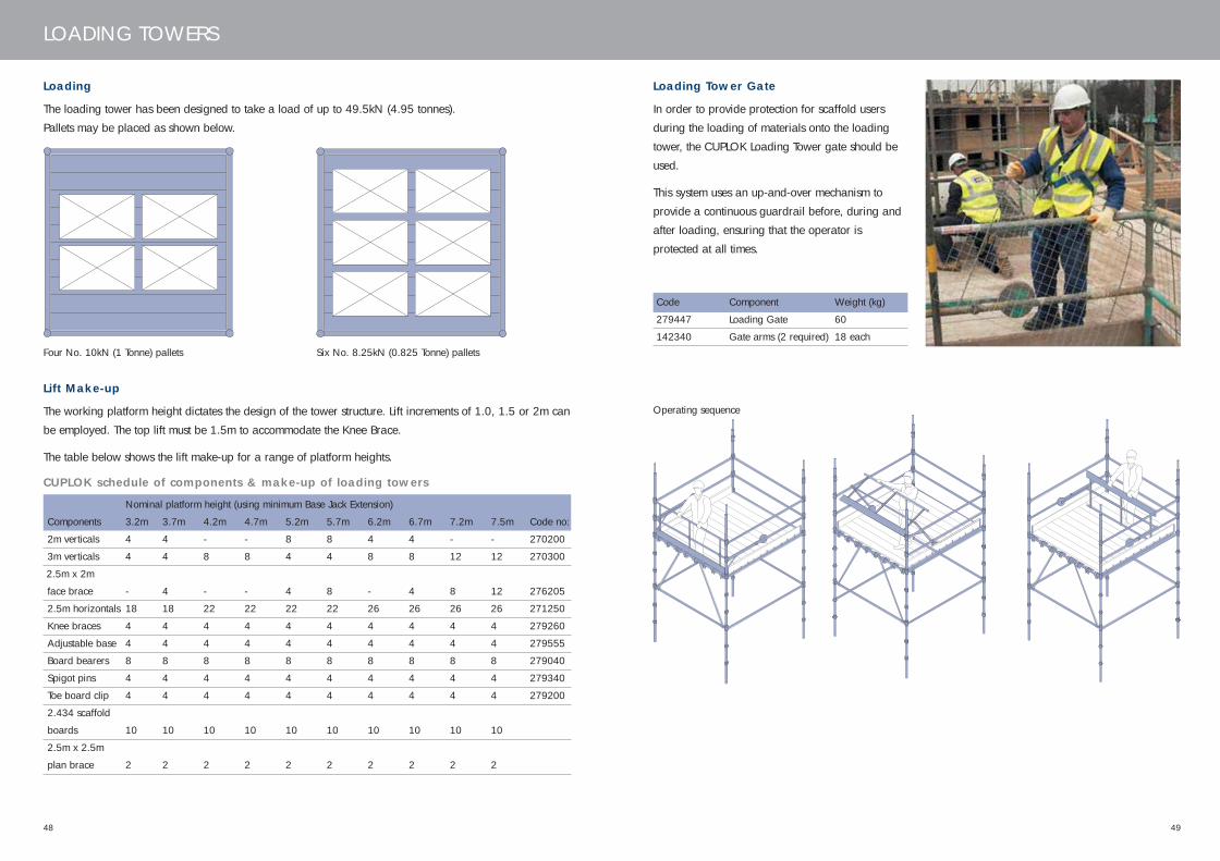
Loading Tower Gate
In order to provide protection for scaffold users
during the loading of materials onto the loading
tower, the CUPLOK Loading Tower gate should be
used.
This system uses an up-and-over mechanism to
provide a continuous guardrail before, during and
after loading, ensuring that the operator is
protected at all times.
Code Component Weight (kg)
279447 Loading Gate 60
142340 Gate arms (2 required) 18 each
Loading
The loading tower has been designed to take a load of up to 49.5kN (4.95 tonnes).
Pallets may be placed as shown below.
Six No. 8.25kN (0.825 Tonne) palletsFour No. 10kN (1 Tonne) pallets
Operating sequence
CUPLOK schedule of components & make-up of loading towers
Nominal platform height (using minimum Base Jack Extension)
Components 3.2m 3.7m 4.2m 4.7m 5.2m 5.7m 6.2m 6.7m 7.2m 7.5m Code no:
2m verticals 4 4 - - 8 8 4 4 - - 270200
3m verticals 4 4 8 8 4 4 8 8 12 12 270300
2.5m x 2m
face brace - 4 - - 4 8 - 4 8 12 276205
2.5m horizontals 18 18 22 22 22 22 26 26 26 26 271250
Knee braces 4 4 4 4 4 4 4 4 4 4 279260
Adjustable base 4 4 4 4 4 4 4 4 4 4 279555
Board bearers 8 8 8 8 8 8 8 8 8 8 279040
Spigot pins 4 4 4 4 4 4 4 4 4 4 279340
Toe board clip 4 4 4 4 4 4 4 4 4 4 279200
2.434 scaffold
boards 10 10 10 10 10 10 10 10 10 10
2.5m x 2.5m
plan brace 2 2 2 2 2 2 2 2 2 2
445.33 CUPLOK USER'S MANUAL_12 12/6/06 11:34 AM Page 48
51
STAIRCASE TOWERS
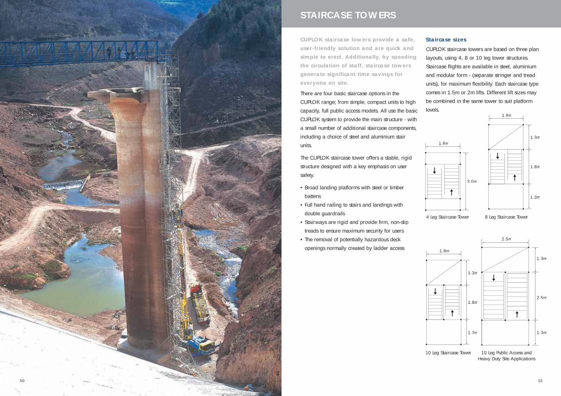
CUPLOK staircase towers provide a safe,user-friendly solution and are quick andsimple to erect. Additionally, by speedingthe circulation of staff, staircase towersgenerate significant time savings foreveryone on site.
There are four basic staircase options in the
CUPLOK range; from simple, compact units to high
capacity, full public access models. All use the basic
CUPLOK system to provide the main structure - with
a small number of additional staircase components,
including a choice of steel and aluminium stair
units.
The CUPLOK staircase tower offers a stable, rigid
structure designed with a key emphasis on user
safety.
• Broad landing platforms with steel or timber
battens
• Full hand railing to stairs and landings with
double guardrails
• Stairways are rigid and provide firm, non-slip
treads to ensure maximum security for users
• The removal of potentially hazardous deck
openings normally created by ladder access
3.0m
1.8m
1.8m
1.3m
1.3m
1.8m
2.5m
1.3m
1.3m
2.5m
1.8m
1.3m
1.3m
1.8m
Staircase sizes
CUPLOK staircase towers are based on three plan
layouts, using 4, 8 or 10 leg tower structures.
Staircase flights are available in steel, aluminium
and modular form - (separate stringer and tread
units), for maximum flexibility. Each staircase type
comes in 1.5m or 2m lifts. Different lift sizes may
be combined in the same tower to suit platform
levels.
4 Leg Staircase Tower 8 Leg Staircase Tower
10 Leg Staircase Tower 10 Leg Public Access and Heavy Duty Site Applications
50
445.33 CUPLOK USER'S MANUAL_12 12/6/06 11:34 AM Page 50

5352
STAIRCASE TOWERS
4-Leg Staircase Tower
Plan area: 1.8m x 3m
The 4 leg stair tower is the most compact staircase
option. It employs the fewest components and can
therefore be erected faster and in more confined
4 Leg Staircase Tower shown using 1.5m staircase units
spaces, giving a convenient and economical access
solution. It can be built in lift heights of 1.5 or 2m
using either aluminium or steel stair units.
445.33 CUPLOK USER'S MANUAL_12 12/6/06 11:34 AM Page 52
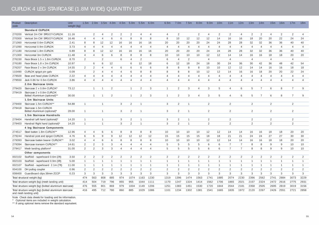
54
CUPLOK 4 LEG STAIRCASE (1.8M WIDE) QUANTITY LIST
Product Description Unit 1.5m 2.0m 3.5m 4.0m 4.5m 5.0m 5.5m 6.0m 6.5m 7.0m 7.5m 8.0m 9.0m 10m 11m 12m 13m 14m 15m 16m 17m 18mcode weight (kg)
Standard CUPLOK270200 Vertical 2m CW SPIGOT-CUPLOK 11.16 2 4 2 2 2 4 4 4 2 2 4 2 2 4 2 2 4 2 2 4270300 Vertical 3m CW SPIGOT-CUPLOK 16.46 4 4 4 6 6 8 8 8 8 10 12 12 12 14 16 16 18 20 20 22 24 24271060 Horizontal 0.6m CUPLOK 2.41 8 8 12 12 16 16 16 16 20 20 20 20 24 24 28 28 32 32 36 36 40 40271090 Horizontal 0.9m CUPLOK 3.73 4 4 4 4 4 4 4 4 4 4 4 4 4 4 4 4 4 4 4 4 4 4271180 Horizontal 1.8m CUPLOK 6.89 8 8 12 12 16 16 16 16 20 20 20 20 24 24 28 28 32 32 36 36 40 40271300 Horizontal 3m CUPLOK 11.48 4 4 6 6 8 8 8 8 10 10 10 10 12 12 14 14 16 16 18 18 20 20276150 Face Brace 1.5 x 1.8m CUPLOK 8.70 2 2 6 4 2 6 4 2 4 4 4 4 4276180 Face Brace 1.8 x 2m CUPLOK 10.97 6 6 12 6 12 18 6 12 18 24 18 30 24 36 30 42 36 48 42 54276207 Face Brace 2 x 3m CUPLOK 14.55 2 2 4 4 6 6 6 6 8 8 8 8 10 10 12 12 14 14 16 16 18 18110490 CUPLOK spigot pin galv 0.09 2 4 4 4 6 8 8 8 8 8 10 12 12 14 16 16 18 20 20 22 24279500 Base and head plate CUPLOK 2.22 4 4 4 4 4 4 4 4 4 4 4 4 4 4 4 4 4 4 4 4 4 4279550 Jack 0.86 for 0.5m CUPLOK 3.86 4 4 4 4 4 4 4 4 4 4 4 4 4 4 4 4 4 4 4 4 4 4
2.0m Staircase Units279420 Staircase 2 x 0.8m CUPLOK* 73.12 1 1 2 1 2 3 1 2 3 4 3 5 4 6 5 7 6 8 7 9279419 Staircase 2 x 0.8m CUPLOK
Bolted Aluminium (optional)** 30.00 1 1 2 1 2 3 1 2 3 4 3 5 4 6 5 7 6 8 7 91.5m Staircase Units
279400 Staircase 1.5m CUPLOK** 54.88 1 1 3 2 1 3 2 1 2 2 2 2 2279418 Staircase 1.5m CUPLOK
Bolted Aluminium (optional)* 28.00 1 1 3 2 1 3 2 1 2 2 2 2 21.5m Staircase Handrails
279404 Handrail Left hand (optional)* 14.20 1 1 3 2 1 3 2 1 2 2 2 2 2279403 Handrail Right hand (optional)* 14.20 1 1 3 2 1 3 2 1 2 2 2 2 2
4 leg Staircase Components274517 Steel batten 1.8m CUPLOK** 12.96 4 4 6 6 8 8 8 8 10 10 10 10 12 12 14 14 16 16 18 18 20 20279244 Handrail post and spigot CUPLOK 4.76 6 6 9 9 12 12 12 12 15 15 15 15 18 18 21 21 24 24 27 27 30 30279393 Staircase batten bearer CUPLOK** 3.02 4 4 6 6 8 8 8 8 10 10 10 10 12 12 14 14 16 16 18 18 20 20279394 Staircase transom CUPLOK** 14.61 2 2 3 3 4 4 4 4 5 5 5 5 6 6 7 7 8 8 9 9 10 10279417 Mesh landing platform* 31.00 2 2 3 3 4 4 4 4 5 5 5 5 6 6 7 7 8 8 9 9 10 10
Other components002102 Scaffold - superboard 0.6m (2ft) 3.50 2 2 2 2 2 2 2 2 2 2 2 2 2 2 2 2 2 2 2 2 2 2002103 Scaffold - superboard 0.9m (3ft) 5.00 1 1 1 1 1 1 1 1 1 1 1 1 1 1 1 1 1 1 1 1 1 1002107 Scaffold - superboard 2.1m (7ft) 11.00 1 1 1 1 1 1 1 1 1 1 1 1 1 1 1 1 1 1 1 1 1 1004100 DH putlog coupler 0.96 2 2 2 2 2 2 2 2 2 2 2 2 2 2 2 2 2 2 2 2 2 2008400 Guardboard clips 38mm ZCCP 0.23 3 3 3 3 3 3 3 3 3 3 3 3 3 3 3 3 3 3 3 3 3 3Total structural weight (kg) 474 563 808 885 974 1074 1163 1230 1319 1396 1474 1563 1741 1885 2074 2230 2396 2562 2741 2884 3073 3229Total structure weight (kg) (mesh landing unit) 414 504 719 796 855 955 1044 1111 1170 1247 1324 1414 1562 1706 1865 2021 2157 2324 2472 2616 2775 2931Total structure weight (kg) (bolted aluminium staircase) 476 555 801 869 979 1004 1149 1206 1251 1383 1451 1530 1720 1844 2044 2181 2358 2505 2695 2819 3019 3156Total structure weight (kg) (bolted aluminium staircase 416 495 712 780 860 885 1029 1086 1101 1234 1302 1381 1541 1665 1835 1972 2120 2267 2426 2551 2721 2858and mesh landing unit)Note Check data sheets for loading and tie information. * Optional items are included in weight calculation. ** If using optional items remove the standard equivalent.
55
445.33 CUPLOK USER'S MANUAL_12 12/6/06 11:34 AM Page 54

5756
STAIRCASE TOWERS
8 Leg Staircase Tower
Plan area: 1.8m x 4.4m
This larger configuration can be built to a height of
38m, subject to ties and loadings. Landing
platforms are 1.3m wide and the staircase is 0.8m
wide. It can be built in lift heights of 1.5 or 2m and
using either aluminium or steel stair units.
The plan module is 4.4m long overall,
incorporating a centre bay of 1.8m and two 1.3m
8 Leg Staircase Tower shown using 2.0m staircase units
landing modules at either end. Omega transoms
are used in conjunction with timber or steel battens
to form the landing platforms. The width of the
tower is 1.8m. Exit from the tower at upper levels is
made from the top landing platform by removing
the appropriate guardrail.
445.33 CUPLOK USER'S MANUAL_12 12/6/06 11:34 AM Page 56
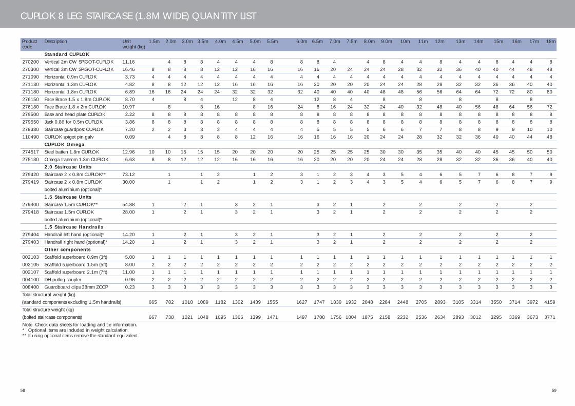
58
CUPLOK 8 LEG STAIRCASE (1.8M WIDE) QUANTITY LIST
Product Description Unit 1.5m 2.0m 3.0m 3.5m 4.0m 4.5m 5.0m 5.5m 6.0m 6.5m 7.0m 7.5m 8.0m 9.0m 10m 11m 12m 13m 14m 15m 16m 17m 18mcode weight (kg)
Standard CUPLOK270200 Vertical 2m CW SPIGOT-CUPLOK 11.16 4 8 8 4 4 4 8 8 8 4 4 8 4 4 8 4 4 8 4 4 8270300 Vertical 3m CW SPIGOT-CUPLOK 16.46 8 8 8 8 12 12 16 16 16 16 20 24 24 24 28 32 32 36 40 40 44 48 48271090 Horizontal 0.9m CUPLOK 3.73 4 4 4 4 4 4 4 4 4 4 4 4 4 4 4 4 4 4 4 4 4 4 4271130 Horizontal 1.3m CUPLOK 4.82 8 8 12 12 12 16 16 16 16 20 20 20 20 24 24 28 28 32 32 36 36 40 40271180 Horizontal 1.8m CUPLOK 6.89 16 16 24 24 24 32 32 32 32 40 40 40 40 48 48 56 56 64 64 72 72 80 80276150 Face Brace 1.5 x 1.8m CUPLOK 8.70 4 8 4 12 8 4 12 8 4 8 8 8 8 8276180 Face Brace 1.8 x 2m CUPLOK 10.97 8 8 16 8 16 24 8 16 24 32 24 40 32 48 40 56 48 64 56 72279500 Base and head plate CUPLOK 2.22 8 8 8 8 8 8 8 8 8 8 8 8 8 8 8 8 8 8 8 8 8 8 8279550 Jack 0.86 for 0.5m CUPLOK 3.86 8 8 8 8 8 8 8 8 8 8 8 8 8 8 8 8 8 8 8 8 8 8 8279380 Staircase guardpost CUPLOK 7.20 2 2 3 3 3 4 4 4 4 5 5 5 5 6 6 7 7 8 8 9 9 10 10110490 CUPLOK spigot pin galv 0.09 4 8 8 8 8 12 16 16 16 16 16 20 24 24 28 32 32 36 40 40 44 48
CUPLOK Omega274517 Steel batten 1.8m CUPLOK 12.96 10 10 15 15 15 20 20 20 20 25 25 25 25 30 30 35 35 40 40 45 45 50 50275130 Omega transom 1.3m CUPLOK 6.63 8 8 12 12 12 16 16 16 16 20 20 20 20 24 24 28 28 32 32 36 36 40 40
2.0 Staircase Units279420 Staircase 2 x 0.8m CUPLOK** 73.12 1 1 2 1 2 3 1 2 3 4 3 5 4 6 5 7 6 8 7 9279419 Staircase 2 x 0.8m CUPLOK 30.00 1 1 2 1 2 3 1 2 3 4 3 5 4 6 5 7 6 8 7 9
bolted aluminium (optional)*1.5 Staircase Units
279400 Staircase 1.5m CUPLOK** 54.88 1 2 1 3 2 1 3 2 1 2 2 2 2 2279418 Staircase 1.5m CUPLOK 28.00 1 2 1 3 2 1 3 2 1 2 2 2 2 2
bolted aluminium (optional)*1.5 Staircase Handrails
279404 Handrail left hand (optional)* 14.20 1 2 1 3 2 1 3 2 1 2 2 2 2 2279403 Handrail right hand (optional)* 14.20 1 2 1 3 2 1 3 2 1 2 2 2 2 2
Other components002103 Scaffold superboard 0.9m (3ft) 5.00 1 1 1 1 1 1 1 1 1 1 1 1 1 1 1 1 1 1 1 1 1 1 1002105 Scaffold superboard 1.5m (5ft) 8.00 2 2 2 2 2 2 2 2 2 2 2 2 2 2 2 2 2 2 2 2 2 2 2002107 Scaffold superboard 2.1m (7ft) 11.00 1 1 1 1 1 1 1 1 1 1 1 1 1 1 1 1 1 1 1 1 1 1 1004100 DH putlog coupler 0.96 2 2 2 2 2 2 2 2 2 2 2 2 2 2 2 2 2 2 2 2 2 2 2008400 Guardboard clips 38mm ZCCP 0.23 3 3 3 3 3 3 3 3 3 3 3 3 3 3 3 3 3 3 3 3 3 3 3Total structural weight (kg)(standard components excluding 1.5m handrails) 665 782 1018 1089 1182 1302 1439 1555 1627 1747 1839 1932 2048 2284 2448 2705 2893 3105 3314 3550 3714 3972 4159Total structure weight (kg) (bolted staircase components) 667 738 1021 1048 1095 1306 1399 1471 1497 1708 1756 1804 1875 2158 2232 2536 2634 2893 3012 3295 3369 3673 3771Note Check data sheets for loading and tie information. * Optional items are included in weight calculation. ** If using optional items remove the standard equivalent.
59
445.33 CUPLOK USER'S MANUAL_12 12/6/06 11:34 AM Page 58

6160
STAIRCASE TOWERS
10 Leg Staircase Tower
Plan area: 1.8m x 4.4m
Suitable for heights up to 53m and heavier loading
requirements, this staircase is similar in layout to
the 8 legged tower, but incorporates two additional
central standards at the inside ends of the staircase
flights. Landing platforms are 1.3m wide, the
staircase is 0.8m wide. It can be built in lift heights
of 1.5 or 2m and using either aluminium or steel
stair units.
10 Leg Staircase Tower shown using 2.0m staircase units
445.33 CUPLOK USER'S MANUAL_12 12/6/06 11:34 AM Page 60

62
CUPLOK 10 LEG STAIRCASE (1.8M WIDE) QUANTITY LIST
Product Description Unit 1.5m 2.0m 3.0m 3.5m 4.0m 4.5m 5.0m 5.5m 6.0m 6.5m 7.0m 7.5m 8.0m 9.0m 10m 11m 12m 13m 14m 15m 16m 17m 18mcode weight (kg)
Standard CUPLOK270200 Vertical 2m CW SPIGOT-CUPLOK 11.16 5 10 10 5 5 5 10 10 10 5 30 5 10 5 5 10 5 5 10 5 5 10270300 Vertical 3m CW SPIGOT-CUPLOK 16.46 10 10 10 10 15 15 20 20 20 20 25 24 30 30 35 40 40 45 50 50 55 60 60271090 Horizontal 0.9m CUPLOK 3.73 12 12 16 16 16 20 20 20 20 24 24 20 24 28 28 32 32 36 36 40 40 44 44271130 Horizontal 1.3m CUPLOK 4.82 8 8 12 12 12 16 16 16 16 20 20 35 20 24 24 28 28 32 32 36 36 40 40271180 Horizontal 1.8m CUPLOK 6.89 14 14 21 21 21 28 28 28 28 35 35 10 35 42 42 49 49 56 56 63 63 70 70279500 Base and head plate CUPLOK 2.22 10 10 10 10 10 10 10 10 10 10 10 10 10 10 10 10 10 10 10 10 10 10 10279550 Jack 0.86 for 0.5m CUPLOK 3.86 10 10 10 10 10 10 10 10 10 10 10 4 10 10 10 10 10 10 10 10 10 10 10276150 Face brace 1.5 x 1.8m CUPLOK 8.70 4 8 4 12 8 4 12 8 24 8 8 8 8 8276180 Face brace 1.8 x 2m CUPLOK 10.97 8 8 16 8 16 24 8 16 20 32 24 40 32 48 40 56 48 64 56 72110490 CUPLOK spigot pin galv 0.09 5 10 10 10 10 15 20 20 20 20 25 30 30 35 40 40 45 50 50 55 60
CUPLOK Omega274517 Steel batten 1.8m CUPLOK 12.96 10 10 15 15 15 20 20 20 20 25 25 25 25 30 30 35 35 40 40 45 45 50 50275130 Omega transom 1.3m CUPLOK 6.63 8 8 12 12 12 16 16 16 16 20 20 20 20 24 24 28 28 32 32 36 36 40 40
2.0 Staircase Units279420 Staircase 2 x 0.8m CUPLOK steel** 73.12 1 1 2 1 2 3 1 2 3 4 3 5 4 6 5 7 6 8 7 9279419 Staircase 2 x 0.8m CUPLOK 30.00 1 1 2 1 2 3 1 2 3 4 3 5 4 6 5 7 6 8 7 9
bolted aluminium (optional)*279400 Staircase 1.5m CUPLOK** steel 54.88 1 2 1 3 2 1 3 2 1 2 2 2 2 2279418 Staircase 1.5m CUPLOK 28.00 1 2 1 3 2 1 3 2 1 2 2 2 2 2
bolted aluminium (optional)*1.5 Staircase Handrails
279404 Handrail left hand (optional)* 14.20 1 2 1 3 2 1 3 2 1 2 2 2 2 2279403 Handrail right hand (optional)* 14.20 1 2 1 3 2 1 3 2 1 2 2 2 2 2
Other components002103 Scaffold superboard 0.9m (3ft) 5.00 1 1 1 1 1 1 1 1 1 1 1 1 1 1 1 1 1 1 1 1 1 1 1002105 Scaffold superboard 1.5m (5ft) 8.00 2 2 2 2 2 2 2 2 2 2 2 2 2 2 2 2 2 2 2 2 2 2 2002107 Scaffold superboard 2.1m (7ft) 11.00 1 1 1 1 1 1 1 1 1 1 1 1 1 1 1 1 1 1 1 1 1 1 1004100 DH putlog coupler 0.96 2 2 2 2 2 2 2 2 2 2 2 2 2 2 2 2 2 2 2 2 2 2 2008400 Guardboard clips 38mm ZCCP 0.23 3 3 3 3 3 3 3 3 3 3 3 3 3 3 3 3 3 3 3 3 3 3 3Total structural weight (kg)(standard components excluding 1.5m handrails) 712 840 1088 1159 1257 1378 1532 1659 1731 1852 1949 2047 2174 2423 2592 2867 3065 3284 3509 3758 3927 4202 4400Total structure weight (kg)(bolted staircase components) 714 796 1091 1118 1171 1383 1492 1575 1601 1813 1866 1919 2002 2297 2376 2697 2807 3072 3207 3502 3582 3903 4012Note Check data sheets for loading and tie information. * Optional items (shaded) are included in weight calculation. ** If using optional items remove the standard equivalent.
63
445.33 CUPLOK USER'S MANUAL_12 12/6/06 11:34 AM Page 62

64
CUPLOK 10 LEG STAIRCASE (2.5M WIDE) QUANTITY LIST
Product Description Unit 1.5m 2.0m 3.0m 3.5m 4.0m 4.5m 5.0m 5.5m 6.0m 6.5m 7.0m 7.5m 8.0m 9.0m 10m 11m 12m 13m 14m 15m 16m 17m 18mcode weight (kg)
Standard CUPLOK270200 Vertical 2m CW SPIGOT-CUPLOK 11.16 5 10 10 5 5 5 10 10 10 5 5 10 5 5 10 5 5 10 5 5 10270300 Vertical 3m CW SPIGOT-CUPLOK 16.46 10 10 10 10 15 15 20 20 20 20 25 30 30 30 35 40 40 45 50 50 55 60 60271127 Horizontal 1.25m CUPLOK 4.76 12 12 16 16 16 20 20 20 20 24 24 24 24 28 28 32 32 36 36 40 40 44 44271130 Horizontal 1.3m CUPLOK 4.86 8 8 12 12 12 16 16 16 16 20 20 20 20 24 24 28 28 32 32 36 36 40 40271250 Horizontal 2.5m CUPLOK 9.48 14 14 21 21 21 28 28 28 28 35 35 35 35 42 42 49 49 56 56 63 63 70 70279500 Base and head plate CUPLOK 2.22 10 10 10 10 10 10 10 10 10 10 10 10 10 10 10 10 10 10 10 10 10 10 10279550 Jack 0.86 for 0.5m CUPLOK 3.86 10 10 10 10 10 10 10 10 10 10 10 10 10 10 10 10 10 10 10 10 10 10 10276153 Face brace 1.5 x 2.5m CUPLOK 10.70 4 8 4 12 8 4 12 8 4 8 8 8 8 8276203 Face brace 2 x 2.5m CUPLOK 12.90 8 8 16 8 16 24 8 16 24 32 24 40 32 48 40 56 48 64 56 72110490 CUPLOK spigot pin galv 0.09 5 10 10 10 10 15 20 20 20 20 20 25 30 30 35 40 40 45 50 50 55 60
CUPLOK Omega274525 Steel batten 2.5m CUPLOK 17.46 10 10 15 15 15 20 20 20 20 25 25 25 25 30 30 35 35 40 40 45 45 50 50275130 Omega transom 1.3m CUPLOK 6.63 8 8 12 12 12 16 16 16 16 20 20 20 20 24 24 28 28 32 32 36 36 40 40
2.0 Staircase Units279370 Staircase 2.0m Pubaac Alum** 75.29 1 1 2 1 2 3 1 2 3 4 3 5 4 6 5 7 6 8 7 9279398 Steel staircase
2.0m x 2.5m x 1.06m 125.08 1 1 2 1 2 3 1 2 3 4 3 5 4 6 5 7 6 8 7 9279791 Mod stair left hand stile assembly
2.0m x 2.5m (optional)* 31.87 1 1 2 1 2 3 1 2 3 4 3 5 4 6 5 7 6 8 7 9279790 Mod stair right hand stile assembly
2.0m x 2.5m (optional)* 31.87 1 1 2 1 2 3 1 2 3 4 3 5 4 6 5 7 6 8 7 9279795 Mod treads steel 1.04m (optional)* 6.00 10 10 20 10 20 30 10 20 30 40 30 50 40 60 50 70 60 80 70 90
1.5 Staircase Units279369 Staircase unit 1.5m Pubacc Alum** 67.13 1 2 1 3 2 1 3 2 1 2 2 2 2 2279797 Mod stair left hand stile
assembly 1.5m x 2.5m (optional)* 29.30 1 2 1 3 2 1 3 2 1 2 2 2 2 2279796 Mod stair right hand stile
assembly 1.5m x 2.5m (optional)* 29.30 1 2 1 3 2 1 3 2 1 2 2 2 2 2279795 Mod treads steel 1.04m (optional)* 6.00 10 20 10 30 20 10 30 20 10 20 20 20 20 20
1.5 Staircase Handrails278807 Handrail - left hand (optional)* 17.40 1 2 1 3 2 1 3 2 1 2 2 2 2 2279806 Handrail - right hand (optional)* 17.40 1 2 1 3 2 1 3 2 1 2 2 2 2 2
Other components002105 Scaffold superboard 1.5m (5ft) 8.00 3 3 3 3 3 3 3 3 3 3 3 3 3 3 3 3 3 3 3 3 3 3 3002110 Scaffold superboard 3.1m (10ft) 11.00 1 1 1 1 1 1 1 1 1 1 1 1 1 1 1 1 1 1 1 1 1 1 1004100 DH putlog coupler 0.96 2 2 2 2 2 2 2 2 2 2 2 2 2 2 2 2 2 2 2 2 2 2 2008400 Guardboard clips 38mm ZCCP 0.23 3 3 3 3 3 3 3 3 3 3 3 3 3 3 3 3 3 3 3 3 3 3 3Total Structure Weight (kg) (Standard Components) 829 954 1270 1339 1434 1625 1777 1902 1970 2162 2257 2352 2477 2793 2956 3299 3493 3779 3999 4315 4479 4822 5015Total Structure Weight (kg) (Modular Staircase Components) 916 1003 1443 1474 1531 1884 1998 2085 2115 2469 2526 2583 2670 3111 3199 3666 3783 4194 4338 4779 4867 5333 5451Total Structure Weight (kg) (Steel 2.0m x 2.5m x 1.06m Staircase) 829 1004 1270 1389 1534 1625 1827 2001 2120 2211 2356 2501 2676 2942 3205 3498 3791 4028 4348 4614 4877 5170 5463Note Check data sheets for loading and tie information. * Optional items are included in weight calculation. ** If using optional items remove the standard equivalent.
65
445.33 CUPLOK USER'S MANUAL_12 12/6/06 11:34 AM Page 64

6766
STAIRCASE TOWERS
CUPLOK Public Access Staircase
The CUPLOK Public Access Staircase is designed to
meet the more demanding standards required for
use by the public. Based on the 10 leg staircase
tower plan, it uses 1m wide aluminium staircase
units for high capacity and ease of assembly, and
can be built in lifts of 1.5 or 2m. Loading can be
up to 5kN per m2.
Public Access Staircase
The CUPLOK Public Access Staircase is designed to
comply with the following standards:
• BS 5395 Part 1 2000, Stairs, ladders and
Walkways
• Building Regulations, Documents A and K
• BS 6180, Code of Practice for Barriers in and
About Buildings
• BS 6399-1, Loadings on Buildings
• BS EN 12811-1: 2003: Part 1 Scaffolds,
Performance requirements and general design
445.33 CUPLOK USER'S MANUAL_12 12/6/06 11:34 AM Page 66
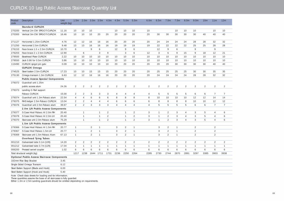
68
CUPLOK 10 Leg Public Access Staircase Quantity List
Product Description Unit 1.5m 2.0m 3.0m 3.5m 4.0m 4.5m 5.0m 5.5m 6.0m 6.5m 7.0m 7.5m 8.0m 9.0m 10m 11m 12mcode weight (kg)
Standard CUPLOK270200 Vertical 2m CW SPIGOT-CUPLOK 11.16 10 10 10 10 10 10 10 10 10 10 10 10270300 Vertical 3m CW SPIGOT-CUPLOK 16.46 10 10 10 20 20 20 20 20 20 30 30 30 30 30 40 40 40
271127 Horizontal 1.25m CUPLOK 4.76 12 12 16 16 16 20 20 20 20 24 24 24 24 28 28 32 32271250 Horizontal 2.5m CUPLOK 9.48 13 13 16 16 16 19 19 19 19 22 22 22 22 25 25 28 28276153 Face brace 1.5 x 2.5m CUPLOK 10.70 6 9 6 12 9 6 12 9 6 9 9276203 Face brace 2 x 2.5m CUPLOK 12.90 6 3 9 3 6 12 3 6 9 15 9 18 12 21279500 Basehead Plate CUPLOK 2.22 10 10 10 10 10 10 10 10 10 10 10 10 10 10 10 10 10279550 Jack 0.86 for 0.5m CUPLOK 3.86 10 10 10 10 10 10 10 10 10 10 10 10 10 10 10 10 10110490 CUPLOK spigot pin galv 0.09 10 10 10 10 10 20 20 20 20 20 20 30 30 30 30 40 40
CUPLOK Omega274525 Steel batten 2.5m CUPLOK 17.23 10 10 15 15 15 20 20 20 20 25 25 25 25 30 30 35 35275130 Omega transom 1.3m CUPLOK 6.63 12 12 16 16 16 20 20 20 20 24 24 24 24 28 28 32 32
Public Access Special Components279372 Guardrail unit 1.25m
public access alum 24.26 2 2 2 2 2 2 2 2 2 2 2 2 2 2 2 2 2279373 Landing G Rail support
Pubacc CUPLOK 15.00 2 2 3 3 3 4 4 4 4 5 5 5 5 6 6 7 7279374 Guardrail unit 1.3m Pubacc alum 22.54 4 4 6 6 6 8 8 8 8 10 10 10 10 12 12 14 14279375 RHS ledger 2.5m Pubacc CUPLOK 13.04 2 2 4 4 4 6 6 6 6 8 8 8 8 10 10 12 12279376 Guardrail unit 2.5m Pubacc alum 39.67 2 2 3 3 3 4 4 4 4 5 5 5 5 6 6 7 7
2.0m Lift Public Access Components279377 S Case Hrail Pubacc Al 2.0m RH 20.40 1 1 2 1 2 3 1 2 3 4 3 5 4 6279378 S Case Hrail Pubacc Al 2.0m LH 20.40 1 1 2 1 2 3 1 2 3 4 3 5 4 6279370 Staircase unit 2.0m Pubacc alum 75.29 1 1 2 1 2 3 1 2 3 4 3 5 4 6
1.5m Lift Public Access Components279366 S Case Hrail Pubacc Al 1.5m RH 20.77 1 2 1 3 2 1 3 2 1 2 2279367 S Case Hrail Pubacc 1.5m LH 20.77 1 2 1 3 2 1 3 2 1 2 2279369 Staircase unit 1.5m Pubacc Alum 67.13 1 2 1 3 2 1 3 2 1 2 2
Overhead Tying Tubes001210 Galvanised tube 3.1m (10ft) 14.20 2 2 2 2 2 2 2 2 2 2 2 2 2 2 2 2 2001212 Galvanised tube 3.7m (12ft) 17.04 1 1 1 1 1 1 1 1 1 1 1 1 1 1 1 1 1006200 Pressed swivel coupler 1.02 6 6 6 6 6 6 6 6 6 6 6 6 6 6 6 6 6Total structural weight (kg) 1217 1238 1644 1711 1731 2236 2250 2264 2285 2730 2744 2870 2891 3297 3385 3903 3938Optional Public Access Staircase Components182mm Rise Step Bracket 3.45Single Sided Omega Transom 6.12Steel Batten Support (Blade and Hook) 6.00Steel Batten Support (Hook and Hook) 5.40Note Check data sheets for loading and tie information. These quantities assume the base of all staircases is fully guarded. Either 1.3m or 2.5m Landing guardrails should be omitted depending on requirements.
69
445.33 CUPLOK USER'S MANUAL_12 12/6/06 11:34 AM Page 68
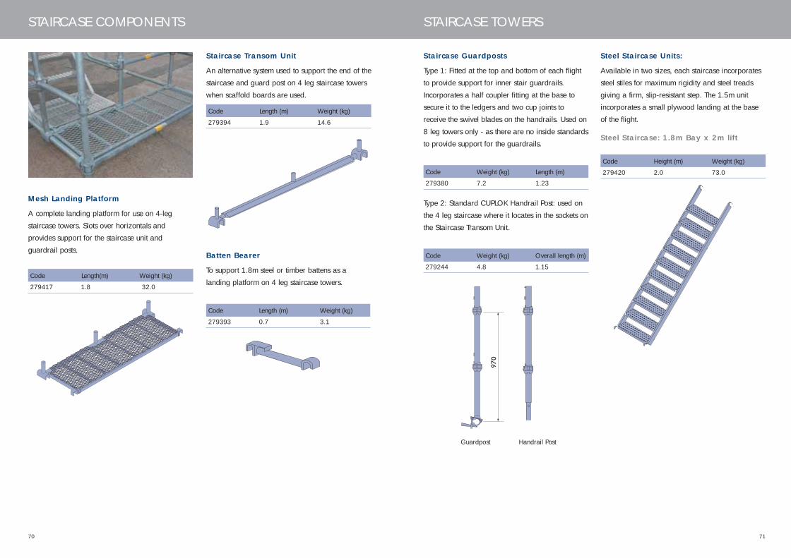
Mesh Landing Platform
A complete landing platform for use on 4-leg
staircase towers. Slots over horizontals and
provides support for the staircase unit and
guardrail posts.
7170
STAIRCASE COMPONENTS
Code Length (m) Weight (kg)
279394 1.9 14.6
Staircase Transom Unit
An alternative system used to support the end of the
staircase and guard post on 4 leg staircase towers
when scaffold boards are used.
Batten Bearer
To support 1.8m steel or timber battens as a
landing platform on 4 leg staircase towers.
Code Length (m) Weight (kg)
279393 0.7 3.1
Staircase Guardposts
Type 1: Fitted at the top and bottom of each flight
to provide support for inner stair guardrails.
Incorporates a half coupler fitting at the base to
secure it to the ledgers and two cup joints to
receive the swivel blades on the handrails. Used on
8 leg towers only - as there are no inside standards
to provide support for the guardrails.
Code Weight (kg) Length (m)
279380 7.2 1.23
970
Type 2: Standard CUPLOK Handrail Post: used on
the 4 leg staircase where it locates in the sockets on
the Staircase Transom Unit.
Code Weight (kg) Overall length (m)
279244 4.8 1.15
Steel Staircase Units:
Available in two sizes, each staircase incorporates
steel stiles for maximum rigidity and steel treads
giving a firm, slip-resistant step. The 1.5m unit
incorporates a small plywood landing at the base
of the flight.
Steel Staircase: 1.8m Bay x 2m lift
Guardpost Handrail Post
Code Height (m) Weight (kg)
279420 2.0 73.0
STAIRCASE TOWERS
Code Length(m) Weight (kg)
279417 1.8 32.0
970
445.33 CUPLOK USER'S MANUAL_12 12/6/06 11:34 AM Page 70
7372
STAIRCASE TOWERS
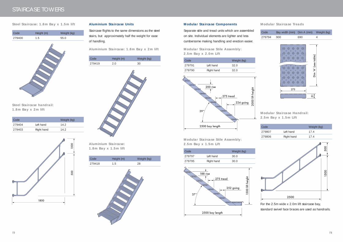
Steel Staircase: 1.8m Bay x 1.5m lift
Steel Staircase handrail: 1.8m Bay x 2m lift
Aluminium Staircase Units
Staircase flights to the same dimensions as the steel
stairs, but approximately half the weight for ease
of handling.
Aluminium Staircase: 1.8m Bay x 2m lift
For the 2.5m wide x 2.0m lift staircase bay,
standard swivel face braces are used as handrails.
Aluminium Staircase: 1.8m Bay x 1.5m lift
Code Height (m) Weight (kg)
279400 1.5 55.0
Code Weight (kg)
279404 Left hand 14.2
279403 Right hand 14.2
Code Height (m) Weight (kg)
279419 2.0 30
Code Height (m) Weight (kg)
279418 1.5 28
1800
500
1500
Modular Staircase Components
Separate stile and tread units which are assembled
on site. Individual elements are lighter and less
cumbersome making handling and erection easier.
Modular Staircase Stile Assembly: 2.5m Bay x 2.0m Lift
Modular Staircase Stile Assembly: 2.5m Bay x 1.5m Lift
Modular Staircase Treads
Modular Staircase Handrail: 2.5m Bay x 1.5m Lift
Code Weight (kg)
279791 Left hand 32.0
279790 Right hand 32.0
Code Weight (kg)
279797 Left hand 30.0
279795 Right hand 30.0
Code Bay width (mm) Dim A (mm) Weight (kg)
279794 900 690 4
Code Weight (kg)
279807 Left hand 17.4
279806 Right hand 17.4
224 going
2000
lift
heig
ht
2500 bay length
275 tread
200 rise
39°
252 going
1500
lift
heig
ht
2500 bay length
275 tread
188 rise
37°
Dim
ʻAʼ (
see
tabl
e)51
275
2500
500
1500
445.33 CUPLOK USER'S MANUAL_12 12/6/06 11:34 AM Page 72

7574
STAIRCASE TOWERS
CUPLOK Public Access StaircaseComponents
Public Access Aluminium Staircase: 2.5m Bay x 2m lift
Aluminium Staircase: 2.5m Bay x 1.5m lift
Handrail: 2.5m bay x 2.0m Lift
Handrail: 2.5m bay x 1.5m Lift
Code Weight (kg)
279370 75.3
Code Weight (kg)
279369 67.0
Code Weight (kg)
279367 Left hand 20.77
279366 Right hand 20.77
Code Weight (kg)
279378 Left hand 20.4
279377 Right hand 20.4
944
500
500
2000
944 50
0
500
1500
Plate for resisting handrail againstRHS ledger (Code No 279375)
Intermediate handrail connector
Cuplock forged blades
2.5m Landing Guardrail
1.3m Landing Guardrail
1.25m Landing Guardrail
RHS Ledger with Handrail Fixing Pont
2 Bolt holes to attach verticalstiffening member (Code No 279373)
Code Weight (kg)
279376 39.67
Code Weight (kg)
279372 24.26
Code Weight (kg)
279374 22.54
Code Weight (kg)
279375 13.04
445.33 CUPLOK USER'S MANUAL_12 12/6/06 11:34 AM Page 74

7776
STAIRCASE TOWERS
2.5m Landing Guardrail ReinforcingMember (Mk 1) to Landing GuardrailSupport (Mk 1)
2.5m Landing Guardrail ReinforcingMember (Mk 2) to Landing GuardrailSupport (Mk 2)
Step Bracket – 182mm rise
Used at the base of the tower to support a single
platform tread where the height of the base of the
platform exceeds a comfortable step height.
Attach to land guardrail using Gr 8.8M12 x 50 set screw, full nut & washer
Code Weight (kg)
279373 15.0
Rotating blade fixed with M12 bolt,Nylock nut & washer in 3 Posn
Rotating guardrail connector bracket.Attach to land guardrail using Gr 8.8M12 x 50 set screw, full nut & washer (if required)
Code Weight (kg)
279373 19.0
Code Weight (kg)
279801 3.45
Permissible heights, loading and tying of Staircase Towers
SGB recommends two tying and bracing options as shown in the diagrams below.
Ties must always be rigid and carry loads in two horizontally perpendicular directions. The maximum
distance of a tie to the nearest node point must not exceed 300mm and the staircase tower must not extend
more than 4m above the last tied level when in use. For full information on non-standard types of tower
construction, tie patterns or loading cases, please contact your local SGB branch.
The permissible heights of staircase towers under various loading conditions are shown below.
4 leg* 8 leg 10 leg 10 leg Public Access
Weight per lift Bottom lift 242kg 448kg per 2m lift 472kg per 2m lift 315kg per lift
Middle lift 188kg 270kg per 1.5m base lift 293kg per 1.5m base lift (average)
Top lift 225kg (with no guard rails) (with no guard rails)
Max height 40m loaded to 33m loaded to 45m loaded to 12m loaded to
and load duty 200kg per lift 75kg/m2 per lift (ties 8m) 75kg/m2 per lift (ties 8m) 5kN/m2 vertically
23m loaded to 150kg/m2 32m loaded to 150kg/m2 and 3kN/m2
per lift (ties 8m) per lift (ties 8m) horizontally
38m loaded to 200kg/m2 53m loaded to 200kg/m2 Plan braced at top
per lift (ties 8m) per lift (ties 8m) (ties 6m)
Stair width 535mm 750mm 750mm 1000mm
Tie spacing 8m vertically 4 or 8m vertically 4 or 8m vertically 6m vertically
*For details see SGB Data Sheets
445.33 CUPLOK USER'S MANUAL_12 12/6/06 11:34 AM Page 76
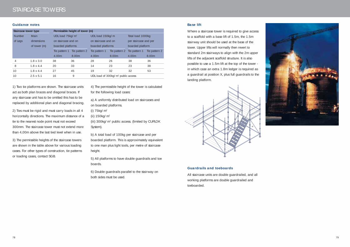
7978
STAIRCASE TOWERS
Guidance notes
Staircase tower type Permissible height of tower (m)
Number Main UDL load 75kg/m2 UDL load 150kg/m Total load 1000kg
of Legs dimensions on staircase and on on staircase and on per staircase and per
of tower (m) boarded platforms boarded platforms boarded platform
Tie pattern 1 Tie pattern 2 Tie pattern 1 Tie pattern 2 Tie pattern 1 Tie pattern 2
4.00m 8.00m 4.00m 8.00m 4.00m 8.00m
4 1.8 x 3.0 38 36 28 26 38 36
8 1.8 x 4.4 20 33 14 23 23 38
10 1.8 x 4.4 27 45 19 32 32 53
10 2.5 x 5.1 16 9 UDL load of 300kg/m2 public access
1) Two tie platforms are shown. The staircase units
act as both plan braces and diagonal braces. If
any staircase unit has to be omitted this has to be
replaced by additional plan and diagonal bracing.
2) Ties must be rigid and must carry loads in all 4
horizontally directions. The maximum distance of a
tie to the nearest node point must not exceed
300mm. The staircase tower must not extend more
than 4,00m above the last tied level when in use.
3) The permissible heights of the staircase towers
are shown in the table above for various loading
cases. For other types of construction, tie patterns
or loading cases, contact SGB.
4) The permissible height of the tower is calculated
for the following load cases:
a) A uniformly distributed load on staircases and
on boarded platforms.
(i) 75kg/m2
(ii) 150kg/m2
(iii) 300kg/m2 public access. (limited by CUPLOK
System).
b) A total load of 100kg per staircase and per
boarded platform. This is approximately equivalent
to one man plus light tools, per metre of staircase
height.
5) All platforms to have double guardrails and toe
boards.
6) Double guardrails parallel to the stairway on
both sides must be used.
X
X
Base lift
Where a staircase tower is required to give access
to a scaffold with a base lift of 1.5m, the 1.5m
stairway unit should be used at the base of the
tower. Upper lifts will normally then revert to
standard 2m stairways to align with the 2m upper
lifts of the adjacent scaffold structure. It is also
possible to use a 1.5m lift at the top of the tower -
in which case an extra 1.8m ledger is required as
a guardrail at position X, plus full guardrails to the
landing platform.
Guardrails and toeboards
All staircase units are double guardrailed, and all
working platforms are double guardrailed and
toeboarded.
445.33 CUPLOK USER'S MANUAL_12 12/6/06 11:34 AM Page 78
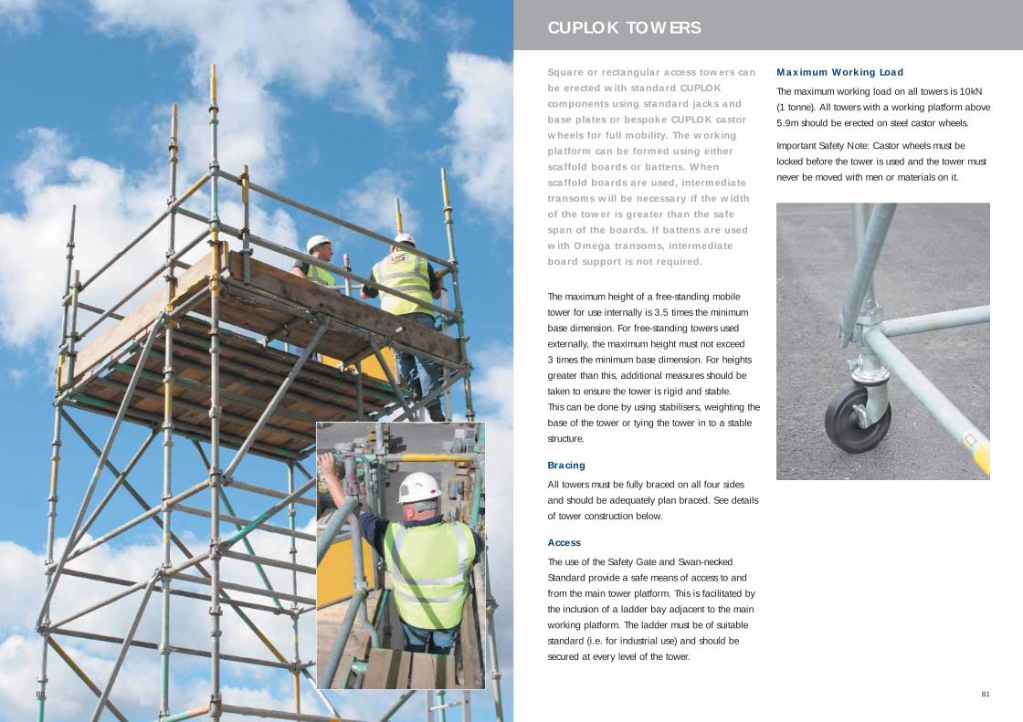
81
Square or rectangular access towers canbe erected with standard CUPLOKcomponents using standard jacks andbase plates or bespoke CUPLOK castorwheels for full mobility. The workingplatform can be formed using eitherscaffold boards or battens. Whenscaffold boards are used, intermediatetransoms will be necessary if the widthof the tower is greater than the safespan of the boards. If battens are usedwith Omega transoms, intermediateboard support is not required.
The maximum height of a free-standing mobile
tower for use internally is 3.5 times the minimum
base dimension. For free-standing towers used
externally, the maximum height must not exceed
3 times the minimum base dimension. For heights
greater than this, additional measures should be
taken to ensure the tower is rigid and stable.
This can be done by using stabilisers, weighting the
base of the tower or tying the tower in to a stable
structure.
Bracing
All towers must be fully braced on all four sides
and should be adequately plan braced. See details
of tower construction below.
Access
The use of the Safety Gate and Swan-necked
Standard provide a safe means of access to and
from the main tower platform. This is facilitated by
the inclusion of a ladder bay adjacent to the main
working platform. The ladder must be of suitable
standard (i.e. for industrial use) and should be
secured at every level of the tower.
CUPLOK TOWERS
Maximum Working Load
The maximum working load on all towers is 10kN
(1 tonne). All towers with a working platform above
5.9m should be erected on steel castor wheels.
Important Safety Note: Castor wheels must be
locked before the tower is used and the tower must
never be moved with men or materials on it.
80
445.33 CUPLOK USER'S MANUAL_12 12/6/06 11:34 AM Page 80

83
CUPLOK FOR SUPPORT STRUCTURES
CUPLOK is widely used for falseworksupport structures. Its high leg load andwide range of components gives thesystem the capacity to tackle virtuallyany soffit support application with acost-effective solution. For formworksupport, a wide number of gridvariations can be created to suitediffering load requirements and deckingsystems.
Benefits
The key advantages of CUPLOK over traditional
scaffolding for support structures are:
• High leg load: 74kN
• Unique node point - 4 connections in one action
• Quick erection and systemized bracing
• 20% lighter than traditional scaffolding
Associated Components:DU-AL Aluminium Beam
Complementing CUPLOK in the creation of
falsework support structures is SGB’s DU-AL
aluminium beam system. Its high strength and low
weight make it easy to handle and quick to erect.
The DU-AL system includes 3 beam profiles. In each
case they are supported in forkheads mounted on
the CUPLOK verticals and fastened in place with a
quick-fixing clamp.
EXTRAGUARD Edge Protection
Mesh barrier panels which clamp on to the DU-AL
beam end to provide edge protection to the
formwork deck. Galvanized and powder coated in
high visibility yellow, the panels also incorporate an
integral toeboard.
CUPLOK Support ComponentsVerticals (Standards)
Support Standards differ from Access Standards by
having no spigot at the head. This allows for the
insertion of jacks which provide adjustable support
beneath the soffit. Support Standards are available
in five sizes and are used in conjunction with 1m,
2m and 3m access standards to cover all soffit
heights.
Code Length (m) Weight (kg)
270233 2.3 11.6
270183 1.8 9.1
270133 1.3 6.6
270083 0.8 4.1
270043 0.4 2.4
500mm
220mm
500mm
80mm
82
445.33 CUPLOK USER'S MANUAL_12 12/6/06 11:34 AM Page 82

8584
CUPLOK FOR SUPPORT STRUCTURES
Horizontals (Ledgers)
Eight different sizes of Ledger, all with symmetrical
blade ends, allow a huge range of grid layouts to
be constructed.
Code Size Weight Overall Colour
(m) (kg) length (mm) Code
271060 0.6 2.65 552 None
271090 0.9 3.73 852 None
271100 1.0 4.10 952 Russet
271120 1.2 4.81 1152 White
271130 1.3 5.17 1252 Yellow
271160 1.6 6.24 1552 Black
271180 1.8 6.96 1752 Green
271250 2.5 9.50 2452 None
Forkheads
Fixed Forkhead
Designed to hold aluminium, steel or traditional
timber beams, Forkheads are used in conjunction
with the Universal Jack to give height adjustment.
Nail holes are provided to allow timber beams to
be fixed in place.
The larger 200 x 186mm forkhead supports SGB
MkII Steel Soldiers when used as horizontal shores.
Code Size (mm) Weight (kg)
279650 200 x 86 3.9
279653 150 x 162 3.7
279657 200 x 186 5.2
Bracing Forkhead
Fixed forkheads, which incorporate locating lugs to
accept jack braces, give the structure extra strength
and rigidity.
Description Code Size Weight
(mm) (kg)
75mm 279676 200 x 86 4.2
150mm 279681 150 x 162 4.0
Rocking Forkhead
Forkheads for supporting slabs with slopes in one
or two directions. Secondary sloping is achieved by
rotating the small handles on the socket at the
bottom of the forkhead. Incorporates a facility for
jack bracing.
See page 97 for maximum permitted slopes for
formwork.
Code Height (mm) Weight (kg)
279686 186 6.9
Cantilever Frame
This bracket is designed for supporting cantilever
edge slabs and incorporates 3 Jack locations at
centres of 1.2, 1.25 and 1.3m. All jack locations
can be utilised for traditional primary timbers.
Frames are located in the cup joints. They are of
standard tubular dimension and can be laced
together if used for perimeter access on support
scaffolds
Description Code Overall Weight
length (m) (kg)
For 1.5m Lifts 279615 2.01 20.5
For 1.0m Lifts 279610 1.63 18.5
Guardpost Bracket
Allows the location of a length of standard tube to
form a handrail round the edge of the formwork
deck.
Code Size (mm) Weight (kg)
279700 233 x 65 1.7
Bracing Coupler
Locates on the Base and Head Plates, forkheads
and Adaptors to allow the use of Jack Braces.
Tightened with a butterfly nut.
Code Weight (kg)
279740 0.8
445.33 CUPLOK USER'S MANUAL_12 12/6/06 11:34 AM Page 84
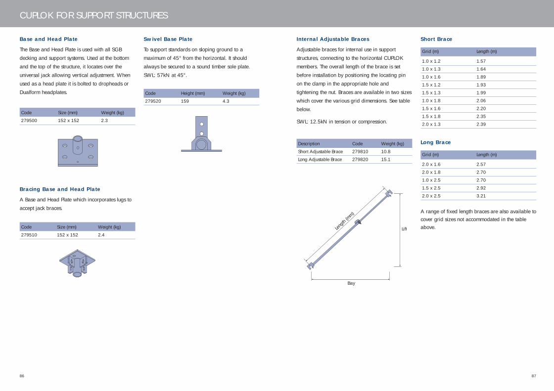
8786
CUPLOK FOR SUPPORT STRUCTURES
Base and Head Plate
The Base and Head Plate is used with all SGB
decking and support systems. Used at the bottom
and the top of the structure, it locates over the
universal jack allowing vertical adjustment. When
used as a head plate it is bolted to dropheads or
Dualform headplates.
Code Size (mm) Weight (kg)
279500 152 x 152 2.3
Bracing Base and Head Plate
A Base and Head Plate which incorporates lugs to
accept jack braces.
Code Size (mm) Weight (kg)
279510 152 x 152 2.4
Swivel Base Plate
To support standards on sloping ground to a
maximum of 45° from the horizontal. It should
always be secured to a sound timber sole plate.
SWL: 57kN at 45°.
Code Height (mm) Weight (kg)
279520 159 4.3
Internal Adjustable Braces
Adjustable braces for internal use in support
structures, connecting to the horizontal CUPLOK
members. The overall length of the brace is set
before installation by positioning the locating pin
on the clamp in the appropriate hole and
tightening the nut. Braces are available in two sizes
which cover the various grid dimensions. See table
below.
SWL: 12.5kN in tension or compression.
Description Code Weight (kg)
Short Adjustable Brace 279810 10.8
Long Adjustable Brace 279820 15.1
Short Brace
Grid (m) Length (m)
1.0 x 1.2 1.57
1.0 x 1.3 1.64
1.0 x 1.6 1.89
1.5 x 1.2 1.93
1.5 x 1.3 1.99
1.0 x 1.8 2.06
1.5 x 1.6 2.20
1.5 x 1.8 2.35
2.0 x 1.3 2.39
Long Brace
Grid (m) Length (m)
2.0 x 1.6 2.57
2.0 x 1.8 2.70
1.0 x 2.5 2.70
1.5 x 2.5 2.92
2.0 x 2.5 3.21
A range of fixed length braces are also available tocover grid sizes not accommodated in the tableabove.Len
gth (m
m)
Lift
Bay
445.33 CUPLOK USER'S MANUAL_12 12/6/06 11:34 AM Page 86
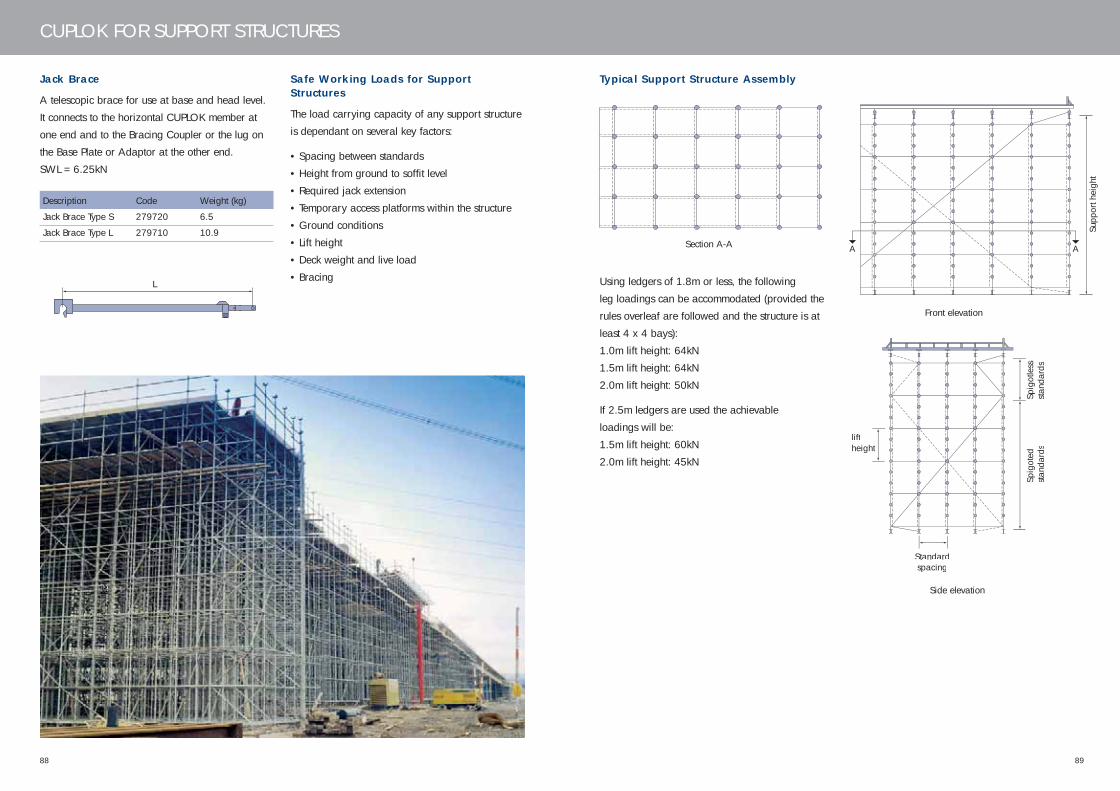
8988
CUPLOK FOR SUPPORT STRUCTURES
Jack Brace
A telescopic brace for use at base and head level.
It connects to the horizontal CUPLOK member at
one end and to the Bracing Coupler or the lug on
the Base Plate or Adaptor at the other end.
SWL = 6.25kN
Description Code Weight (kg)
Jack Brace Type S 279720 6.5
Jack Brace Type L 279710 10.9
Safe Working Loads for SupportStructures
The load carrying capacity of any support structure
is dependant on several key factors:
• Spacing between standards
• Height from ground to soffit level
• Required jack extension
• Temporary access platforms within the structure
• Ground conditions
• Lift height
• Deck weight and live load
• Bracing
Section A-A
Front elevation
Side elevation
Typical Support Structure Assembly
Using ledgers of 1.8m or less, the following
leg loadings can be accommodated (provided the
rules overleaf are followed and the structure is at
least 4 x 4 bays):
1.0m lift height: 64kN
1.5m lift height: 64kN
2.0m lift height: 50kN
If 2.5m ledgers are used the achievable
loadings will be:
1.5m lift height: 60kN
2.0m lift height: 45kN
Supp
ort h
eigh
t
AA
Spig
oted
stand
ards
Standardspacing
liftheight
Spig
otle
sssta
ndar
ds
L
445.33 CUPLOK USER'S MANUAL_12 12/6/06 11:35 AM Page 88
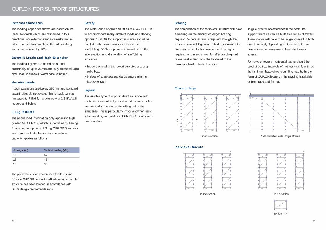
9190
CUPLOK FOR SUPPORT STRUCTURES
External Standards
The loading capacities shown are based on the
inner standards which are restrained in four
directions. For external standards restrained in
either three or two directions the safe working
loads are reduced by 20%.
Eccentric Loads and Jack Extension
The loading figures are based on a load
eccentricity of up to 25mm and fully extended Base
and Head Jacks as a ‘worst case’ situation.
Heavier Loads
If Jack extensions are below 350mm and standard
eccentricities do not exceed 5mm, loads can be
increased to 74kN for structures with 1.5 lifts/1.8
ledgers and below.
3 Lug CUPLOK
The above load information only applies to high
grade SGB CUPLOK, which is identified by having
4 lugs on the top cups. If 3 lug CUPLOK Standards
are introduced into the structure, a reduced
capacity applies as follows:
Lift height (m) Vertical loading (kN)
1.0 57
1.5 45
2.0 33
The permissible loads given for Standards and
Jacks in CUPLOK support scaffolds assume that the
structure has been braced in accordance with
SGB’s design recommendations.
Safety
The wide range of grid and lift sizes allow CUPLOK
to accommodate many different loads and decking
options. CUPLOK for support structures should be
erected in the same manner as for access
scaffolding. SGB can provide information on the
safe erection and dismantling of scaffolding
structures.
• Ledgers placed in the lowest cup give a strong,
solid base
• 5 sizes of spigotless standards ensure minimum
jack extension
Layout
The simplest type of support structure is one with
continuous lines of ledgers in both directions as this
automatically gives accurate setting out of the
standards. This is particularly important when using
a formwork system such as SGB’s DU-AL aluminium
beam system.
Bracing
The composition of the falsework structure will have
a bearing on the amount of ledger bracing
required. Where access is required through the
structure, rows of legs can be built as shown in the
diagram below. In this case ledger bracing is
required across each row. An effective diagonal
brace must extend from the forkhead to the
baseplate level in both directions.
Rows of legs
Individual towers
Section A-A
Front elevation Side elevation with Ledger Braces
Front elevation Side elevation
To give greater access beneath the deck, the
support structure can be built as a series of towers.
These towers will have to be ledger-braced in both
directions and, depending on their height, plan
braces may be necessary to keep the towers
square.
For rows of towers, horizontal lacing should be
used at vertical intervals of not less than four times
the minimum base dimension. This may be in the
form of CUPLOK ledgers if the spacing is suitable
or from tube and fittings.
AA
445.33 CUPLOK USER'S MANUAL_12 12/6/06 11:35 AM Page 90

9392
CUPLOK FOR SUPPORT STRUCTURES
Diagonal braces should be fixed to the ledgers as
shown, as close to the node point as possible.
The maximum gap between the side of the brace
and the node point should be 50mm. The bracing
should be installed immediately after the erection of
each lift to ensure that all bays are properly
squared up.
The quantity of bracing should be calculated, but a
minimum amount must always be used. This
requires one complete brace from the top to the
bottom lacing level, on each row of standards, one
in seven bays in each direction.
Front elevation Side elevation
Detail X of Forkhead Bracing Detail Y of Base Jack Bracing
Jack Bracing with Bracing Adaptor
The Drophead Bracing Adaptor is normally used on
top of the Jack and allows lacing with CUPLOK
ledgers.
Y
X
CuplokLacing
Standard
Jack braceBracing base& head plate
CuplokLacing
Supportstandard
Jack brace
Bracingforkhead
445.33 CUPLOK USER'S MANUAL_12 12/6/06 11:35 AM Page 92

9594
CUPLOK FOR SUPPORT STRUCTURES
Height make-up
The height of the support structure is determined by
the total standard length plus the length taken up
by the jacks, base plates and adaptors. Note that
the standards must always finish with a spigotless
standard at the top so that a jack can be inserted.
The overall height of the various combinations of
standards is shown in the table below.
Care should be taken to make a suitable allowance
in the extension of the top jack for general
adjustment and for striking the formwork.
Total Number of Standards
Standard Support Access
length (m) 1.30 1.80 2.30 1.00 2.00 3.00
1.3 1
1.8 1
2.3 1
2.8 1 1
3.3 1 1
3.8 1 1
4.3 1 1
4.7 1 1
5.3 1 1
5.8 1 2
6.3 1 2
6.8 1 1 1
7.3 2 1 1
7.8 1 2
8.3 1 2
8.8 1 2 1
9.3 1 2 1
9.8 1 1 2
10.3 1 1 2
Top and base adjustment
These diagrams show the overall dimensions of
various component combinations at the top and
base of the structure. Any arrangement at the top
can be combined with any arrangement at the
base. To ascertain the overall length of standards
required, deduct the top and base adjustments from
the overall soffit height.
Top
Bottom
Base plate
Base length
Totalstandardlength
Top length
Jack
Jack
Jack
Supportstandard
Accessstandard
Ledger
Ledger
116-
658
140-
660
6
100
100 34
6
All dimensions are in mm
445.33 CUPLOK USER'S MANUAL_12 12/6/06 11:35 AM Page 94

9796
CUPLOK FOR SUPPORT STRUCTURES
Use of Cantilever Frames
The Cantilever Frame incorporates 3 sockets at 1.2,
1.25 and 1.3m centres to provide support for
cantilever slabs. If the Cantilever Frame is used,
ledgers and bracing must be placed as shown in
the diagram below. The Guardrail Post Bracket can
be connected to the adaptors as shown and will
accept a standard scaffold tube as a guardrail
post.
Bracing and use of Cantilever Frames
Temporary Working Platforms
When a working platform is required just below
soffit level and the bay length exceeds 1.5m then
Intermediate Transoms of 1.2, 1.3, 1.8 or 2.5m can
be used to ensure scaffold boards are supported at
their maximum centres. This will accommodate a
safe working deck without overlapping boards.
Where the Cantilever Frames are used, one or two
additional braces may have to be used, as shown
in the diagram, to cater for the horizontal forces
created at the top and bottom of the cantilever
bracket.
Use of the Rocking Forkhead
The maximum permissible slope of the formwork
can be checked using the graph opposite. After the
grid layout of the scaffold has been established, the
slopes in two directions at right angles along the
grid lines can be ascertained. Note that the
primary bearers must run in the direction of
maximum slope.
Slope along primary beam axis ∝
Intersection of slope angles must lie withinthis envelope
max
. slo
pe a
long
sec
onda
ry b
eam
axi
s ß
1° 2° 3° 4° 5° 6° 7° 8° 9° 10°
7°
6°
5°
4°
3°
2°
1°
Jack brace
Jack
Cuplokstandard
Bracingcoupler
Swivel base plateSw
Timber sole plate
4 No 5/8" dia long steelcoach screws pre base plate
Jack Brace must be fitted inthe direction shown
Use of the Swivel Base Plate
GuardrailpostDrophead
Guardrailpost bracket
Top adjustment
Standards
Cuplok braces
Base adjustments
Cuplok lacing
Cantilever frame
445.33 CUPLOK USER'S MANUAL_12 12/6/06 11:35 AM Page 96
98
SGB reserves the right to alter or amend without notice the design and/or specification of any of the equipment formingpart of the SGB CUPLOK System in the interests of improvement.
99
445.33 CUPLOK USER'S MANUAL_12 12/6/06 11:35 AM Page 98

For further information on this product or any other products and services, please contact yourlocal branch:
tel: 08705 288 388 email: [email protected] www.sgb.co.uk
SGB GroupHarsco House, Regent Park, 299 Kingston Road, Leatherhead, Surrey KT22 7SG Tel: 01372 381300
1006/CDP/5K
CUPLOK USER’S MANUAL
SGB C
UPLO
K U
SER’S MA
NU
AL
SGB Cuplok cover 12/6/06 12:00 PM Page 1