user’s guide - omega engineering · pdf fileuser’s guide ® ® shop on line...
TRANSCRIPT

User’s Guide
®
®
Shop on line at
omega.com
e-mail: [email protected]
For Latest Product Manuals
omegamanual.info
zSeries Wireless Sensor System
zED, zED-P, zED-LCD, zED-LCD-AA, zED-CCELL,zED-DCELL, zED-H, zCDR

It is the policy of OMEGA to comply with all worldwide safety and EMC/EMI regulations that apply. OMEGA is constantly pursuing certification of its products to the European New Approach Directives. OMEGA will add the CE markto every appropriate device upon certification.
The information contained in this document is believed to be correct, but OMEGA Engineering, Inc. accepts no liability for anyerrors it contains, and reserves the right to alter specifications without notice.
WARNING: These products are not designed for use in, and should not be used for, patient-connected applications.
This device is marked with the international caution symbol. It is important to read the Setup Guide before installing or
commissioning this device as the guide contains important information relating to safety and EMC.

i
TABLe oF coNTeNTS
Part 1: Introduction1.1 Safety and EMC Considerations .................................................................2
1.2 Before You Begin..........................................................................................21.3 Description....................................................................................................2
Part 2: Hardware2.1a Parts of the End Device - zED-P/-LCD/-AA ................................................52.1b Parts of the End Device - zED/-CCELL/-DCELL .........................................62.1c Parts of the End Device - zED-LCD-AA-H/zED-CCELL-H..........................72.1d Parts of the End Device - zED .....................................................................82.2a Dimensions and Mounting - End Device - zED-P/-LCD/-AA/-DCELL/-H 92.2b Dimensions and Mounting - End Device - zED .......................................102.3 External Sensors/Probes for the End Device ........................................102.4a Disassembly - End Device - zED-x-P/-LCD...............................................112.4b Disassembly - End Device - zED-x-LCD-AA.............................................122.4c Disassembly - End Device - zED-x-CCELL ..............................................132.4d Disassembly - End Device - zED-x-DCELL ..............................................142.4e Disassembly - End Device - zED-x-LCD-AA-H and zED-x-CCELL-H .....152.4f Disassembly - End Device - zED ...............................................................162.5 Parts of the Coordinator ............................................................................172.6 Dimensions and Mounting - Coordinator.................................................182.7 DIP Switches ...............................................................................................19
2.7.1 DIP Switch Setup: Device ID (DID) .............................................192.7.2 DIP Switch Setup: Network ID (NID) ...........................................212.7.3 DIP Switch Setup: Ethernet - Coordinator .................................22
2.8 Network Communication Interfaces ........................................................232.8.1 10Base-T RJ-45 Pinout .................................................................232.8.2 10Base-T Crossover Wiring .........................................................23
2.9 Thermocouple Wiring ...............................................................................23
Part 3: Network Configuration
3.1 Ethernet (MAC) Address ...........................................................................243.2 Network Protocols .....................................................................................243.3 DHCP .......................................................................................................243.4 DNS .......................................................................................................253.5 IP Address ..................................................................................................25
3.5.1 Default IP Address ........................................................................253.5.2 Changing TCP/IP Properties on Your Computer........................26
Part 4: Operations4.0 Testing the Connection..............................................................................274.1 iConnect Software ......................................................................................284.2 Setting a new IP Address over the Network ...........................................304.3 Coordinator’s Configurations and Operations .......................................31
4.3.1 Power Up Device ..........................................................................324.3.2 Get Readings from the End Device ............................................334.3.3 Java Runtime Environment Setup .............................................354.3.3.1 Java Runtime Environment 1.4 Setup Instructions ...................354.3.3.2 Java Runtime Environment 1.5 (5.0) Setup Instructions ..........364.3.3.3 Browser Proxy Selection .............................................................37

ii
TABLe oF coNTeNTS(continued)
4.3.4 Java Policy ..................................................................................384.3.5 Chart ..............................................................................................404.3.6 Diagnostic .....................................................................................424.3.7 Configuration ................................................................................434.3.8 Sensor Setup.................................................................................444.3.9 Access Control ............................................................................48
4.4 Telnet Setup ...............................................................................................494.5 HTTPget Program ......................................................................................49
4.5.1 HTTPget using Port 2000 ............................................................504.5.2 HTTPget and ARP to Setup Device IP Address .........................50
4.6 ARP Protocol ..............................................................................................524.7 iLog Software..............................................................................................534.8 Mail Notifier Software.................................................................................55
4.8.1 Installation .....................................................................................554.8.2 Program Options Setup and Configuration ..............................564.8.3 Device Setting Setup and Configuration ....................................574.8.4 Sending Text Messages to a Cell Phone ........................................58
Part 5: Environment / Operating Conditions ......................................................................595.1 General Deployment Guidelines .............................................................. 595.2 With Line-of-Sight ......................................................................................615.3 Without Line-of-Sight ................................................................................625.4 Casing and Closure Around the Antenna ................................................625.5 Fine Adjustment in Performance ..............................................................63
Part 6: Specifications .......................................................................................................... 64
Part 7: Factory Preset Values ..............................................................................................69
Appendix A Glossary ......................................................................................................70Appendix B IP Address ..................................................................................................71Appendix C IP Netmask ..................................................................................................72Appendix D ASCII Chart ................................................................................................73
ASCII Chart Control Codes .......................................................................74Appendix E iLog Error Messages ..................................................................................75Appendix F ASCII / Telnet Commands Table................................................................76Appendix G Frequently Asked Questions (FAQ) ..........................................................78Appendix H Warnings and Regulatory Information .....................................................80Appendix I Sensor Information ....................................................................................81

iii
LIST oF FIGUReS:
Figure 1.1 zSeries Wireless System on the Ethernet Network...................................4Figure 2.1a Parts of the End Device - zED-P/-LCD/-AA ................................................5Figure 2.1b Parts of the End Device - zED-CCELL/-DCELL .........................................6Figure 2.1c Parts of the End Device - zED-AA-H/zED-LCD-AA-H ...............................7Figure 2.1d Parts of the End Device - zED ....................................................................8Figure 2.2a Mounting the End Device - zED-P/-LCD/-AA/-DCELL/-H ..........................9Figure 2.2b Mounting the End Device - zED ................................................................10Figure 2.3 External Sensors/Probes ...........................................................................10Figure 2.4a Disassembly of the End Device - zED-x-P/LCD .......................................11Figure 2.4b Disassembly of the End Device - zED-x-LCD-AA ....................................12Figure 2.4c Disassembly of the End Device - zED-x-CCELL ......................................13Figure 2.4c Disassembly of the End Device - zED-x-DCELL ......................................14Figure 2.4e Disassembly of the End Device - zED-x-LCD-AA-H ...............................15Figure 2.4f Disassembly of the End Device - zED ......................................................16Figure 2.5 Parts of the Coordinator ...........................................................................17Figure 2.6 Mounting the Coordinator .......................................................................18Figure 2.7 Device ID (DID) - 8 Position DIP Switch Setup ........................................19Figure 2.8 Network ID (NID) - 8 Position DIP Switch Setup .....................................21Figure 2.9 Ethernet - 4 Position DIP Switch Setup ...................................................22Figure 2.10 RJ45 Pinout ................................................................................................23Figure 2.11 10Base-T Crossover Cable Wiring ...........................................................23Figure 2.12 Thermocouple Wiring & TC Wire Color Chart .........................................23Figure 3.1 4 Position DIP Switch on Bottom Side of Coordinator ..........................24Figure 3.2 Network Connections ...............................................................................26Figure 3.3 Network Connections ...............................................................................26Figure 4.1 Pinging the Coordinator from MS-DOS Prompt .....................................27Figure 4.2 Assigning an IP Address using iConnect ...............................................28Figure 4.3 Accessing the zSeries System for Configuration ..................................29Figure 4.4 Access Control .........................................................................................30Figure 4.5 Home Page Menu .....................................................................................31Figure 4.6 Login and Administrator Password .........................................................31Figure 4.7 Select Readings by Group .......................................................................33Figure 4.8 Readings .....................................................................................................33Figure 4.9 Comma Separated Value Format ...........................................................34Figure 4.10 Java 1.4.2.x Screen Shot ...........................................................................35Figure 4.11 Java 1.5.x.x Screen Shot ...........................................................................36Figure 4.12 Java Policy ..................................................................................................38Figure 4.13 Java Policy ..................................................................................................39Figure 4.14 Select Chart by Group ...............................................................................40Figure 4.15 Chart - End Device #1 LAB 50 ................................................................40Figure 4.16 Diagnostic ...................................................................................................42Figure 4.17 Configuration ............................................................................................43Figure 4.18 Sensor Setup by Group .............................................................................44Figure 4.19 Sensor Setup ..............................................................................................45Figure 4.20a Sensor Parameters ....................................................................................46Figure 4.20b Sensor Parameters for Thermocouple Option .......................................47Figure 4.21 Access Control ..........................................................................................48Figure 4.22 HTTPget Example of Polling End Device #1, 2, 3, 4 ................................50
iv
LIST oF FIGUReS:(continued)
Figure 4.23 ARP Commands and Responses .............................................................52Figure 4.24 iLog Software Logging Data for End Device #1, 3, 4 ..............................53Figure 4.25 Mail Notifier Main Window .........................................................................55Figure 4.26 Mail Notifier Profile Setup..........................................................................56Figure 4.27 Mail Notifier Device Setting ......................................................................58Figure 5.1 Operation in Buildings ..............................................................................60Figure 5.2 Fresnel Zone ..............................................................................................61Figure 5.3 Materials in Buildings ...............................................................................62Figure 5.4 Channels ....................................................................................................63Figure I.1 RH Accuracy Chart ..................................................................................81Figure I.2 Temperature Accuracy Chart ...................................................................81Figure I.3 Normal Range ............................................................................................81
Table 4.1 iLog Excel Applications .............................................................................54Table 4.2 Mail Notfier Commands .............................................................................57Table 6.1 Thermocouple Chart ..................................................................................65Table 6.2 Estimated Battery Lifetime Chart..............................................................67

NoTeS, WARNINGS and cAUTIoNS
Information that is especially important to note is identified by the following labels:
• NOTE • WARNING or CAUTION• IMPORTANT• TIP
NOTE: Provides you with information that is important to successfullysetup and use the zSeries Wireless System.
CAUTION or WARNING: Tells you about the risk of electrical shock.
CAUTION, WARNING or IMPORTANT: Tells you of circumstances orpractices that can affect the instrument’s functionality and must referto accompanying documents.
TIP: Provides you helpful hints.
FeATUReS
Web Server Email Alarms Temperature Humidity Barometric Pressure Dual Thermocouple Input No Special Software
Required
1

2
PART 1
INTRodUcTIoN
1.1 Safety and EMC Considerations
Refer to the Environment/Operating Conditions Section.
Warning: the following parts of the unit are ESD sensitive:
• Plastic connector of the antenna• LCD display• Metal connectors for signal and power• Metal body of the sensor probe
EMC Considerations
• Whenever EMC is an issue, always use shielded cables.• Never run signal and power wires in the same conduit.• Use twisted-pair wires for signal connections.• Install Ferrite Bead(s) on signal wires close to the instrument if EMC problems persist.Failure to follow all instructions and warnings may result in injury!
1.2 Before You Begin
Inspecting Your Shipment: Remove the packing slip and verify that you have receivedeverything listed. Inspect the container and equipment for signs of damage as soon asyou receive the shipment. Note any evidence of rough handling in transit. Immediatelyreport any damage to the shipping agent. The carrier will not honor damage claimsunless all shipping material is saved for inspection. After examining and removing thecontents, save the packing material and carton in the event reshipment is necessary.
Customer Service: If you need assistance, please contact the Customer ServiceDepartment nearest you.
Manuals, Software: The latest Operation Manual as well as free configuration software(iConnect), data-logging software (iLog) and Mail Notifier are available at the websitelisted on the cover page of this manual or on the CD-ROM enclosed with your shipment.
1.3 Description
The zSeries wireless sensor system provides Web-based monitoring of Temperature,Humidity, and Barometric Pressure in critical HVAC and Refrigeration applications.
The compact wireless "End Devices" mount discretely on the wall in clean rooms,laboratories, museums, computer server rooms, warehouses, and any remote facility.
Compact End Devices (zED) are powered by two AA 1.5V alkaline batteries.
High performance, high power End Devices in NEMA4 enclosures come with two choices.The AC version (zED-P/-LCD) is powered by a 5 Vdc universal AC power adapter thatoperates on any voltage worldwide (110 to 240 Vac). Should AC power fail, the unit canoperate on a 3.6V ultra-long-life lithium back-up battery (included).
A number of completely wireless wireless End Devices are powered by two AA (zED-LCD-AA), two C-cell (zED-CCELL), or two D-cell (zED-DCELL) alkaline batteries.These End Devices can operate for weeks, months, or years before changing thebatteries. Battery life depends on the type of sensor and other user settings such as thefrequency of transmission. The zED-DCELL version is not recommended for shock,vibration or in moving equipment.

3
1.3 Description (continued)
The End Devices transmit up to 300 feet/91m (zED) or 3280 feet/1000m (zED-P/-LCD/-AA/-CCELL/-DCELL), without obstructions or interference, to a "Coordinator" connecteddirectly to an Ethernet network and the Internet. The wireless system complies with IEEE802.15.4 operating at 2.4 GHz and the user can switch to different communicationchannels to avoid interference with other wireless technologies (e.g. Wi-Fi).
To achieve robust and reliable wireless communication, End Devices retransmit dataadaptively to the environment so that power consumption is optimized in harsh conditions.The Coordinator also provides error detection mechanism for inactive communication anddiagnostic information including signal strength and data transmission success rate tohelp trouble shooting potential wireless system installation issues.
The zSeries system allows you to monitor and record Temperature, Relative Humidity,and Barometric Pressure over an Ethernet network or the Internet without any specialsoftware-just your Web Browser.
We offer a selection of End Devices for a variety of applications. End Devices can takethermocouple types J, K, T, E, R, S, B, C, N and L (DIN J) measuring temperatures up to2320ºC from two different locations. Also, End Devices are available with built-insensors, with external sensor probes, and with both built-in and external sensors. Theexternal sensors are designed for harsh environments such as outdoor weather, in HVACducts, freezers and refrigerators.
For example, you can select one End Device that has one internal and one external sensorto monitor temperature and humidity both inside and outside a climate-controlled facility.
Each zSeries Coordinator can directly support up to thirty-two (32) End Devices and amaximum of 8 Coordinators can be setup in the vicinity. The Coordinators include ACadapters to operate on any voltage worldwide from 100 to 240 Vac and 50 to 60Hz. TheCoordinator connects directly to an Ethernet Network or the Internet. Unlike an RS232 orUSB device, it does not require a host computer.
The zSeries Coordinator is an independent node on the network sending and receivingdata in standard TCP/IP packets. It is easily configured from a Web Browser and can bepassword protected. From within an Ethernet LAN or over the Internet, the user simplytypes the IP address (such as 192.168.1.200) or an easy to remember name (such as"ServRoom" or "Chicago5") and the Coordinator serves a Web Page with the currentreadings.
The device can trigger an alarm if variables go above or below a set point that youdetermine. Your alarm can be sent by email to a single user or to a group distribution list,including text messages to Internet enabled cell phones and PDA’s. The "Mail Notifier"software is free and easy to use program for this application.
The zSeries wireless sensor system is easy to install, simple to operate, and featuresaward-winning iServer technology with an Embedded Web Server that requires nospecial software.
The zSeries system serves Active Web Pages to display real time readings and charts oftemperature, humidity, and barometric pressure. You can also log data in standard dataformats for use in a spreadsheet or data acquisition program such as Excel or VisualBasic. iLog is a free and easy to use program for logging data to Excel.
The virtual chart viewed on the web page is a Java™ Applet that records a chart over theLAN or Internet in real time. With the zSeries system there is no need to invest time andmoney learning a proprietary software program to log or chart the data.
1.3 Description (continued)
Chart scales are fully adjustable on the fly. For example, the chart can display oneminute, one hour, one day, one week, one month or one year. Temperature and humiditycan be charted across the full span (-40 to 125°C, and 0 to 100% RH) or within anynarrow range such as (20 to 30°C).
The OPC Server software makes it easy to integrate the zSeries wireless sensor systemwith many popular Data Acquisition and Automation programs offered by Omega,Wonderware, iConics, Intellution, Rockwell Automation, and National Instruments,among others.
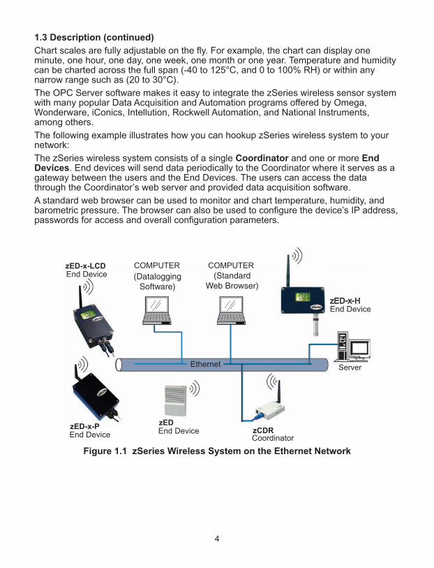
The following example illustrates how you can hookup zSeries wireless system to yournetwork:
The zSeries wireless system consists of a single Coordinator and one or more EndDevices. End devices will send data periodically to the Coordinator where it serves as agateway between the users and the End Devices. The users can access the datathrough the Coordinator’s web server and provided data acquisition software.
A standard web browser can be used to monitor and chart temperature, humidity, andbarometric pressure. The browser can also be used to configure the device’s IP address,passwords for access and overall configuration parameters.
Figure 1.1 zSeries Wireless System on the Ethernet Network
zED
zED-x-LCD
zED-x-P zCDR
Server
4

PART 2 HARdWARe
2.1a Parts of the End Device (zED-P/-LCD/-AA)
1 8 position DIP switch (under cover), sets the NID and DID of the End Device (see Section 2.7 for details)
2 Power Switch
3 Label for Unit Address, Group No. and Network ID Address (NID)
4 Wall mounting holes
5 Label with model and serial numbers
6 Radio module firmware revision location on label
7 Case’s tray, where the PCB, sensor and batteries are mounted
8 Case’s cover
9 Transmit LED (blue)
10 4 Screws attaching Cover
11 External probe/sensor, through cable gland (for zED-TC-x) or quick disconnect connector . Refer to Figure 2.2a for connector configurations.
12 Power Input, through quick disconnect connector (for zED-P & zED-LCD)
13 Antenna Mount
14 Thermocouple (if ordered) removable terminal block connector (under cover)
15 LCD Display (for zED-LCD & zED-LCD-AA)
16 Two AA alkaline batteries (for zED-LCD-AA) or one lithium back-up battery (for zED-P & zED-LCD) (located under cover)
Figure 2.1a Parts of the End Device (zED-P/-LCD/-AA)
POWER
INPUT
5 VDC
SENSOR
INPUT
MODEL #
SERIAL #
#.#
5
6
8 7
2
9
10
15
11
12
Unit Addr Group Net. Addr
FRONT REAR
1
3
4
1314
+ -
+ -
16
Warning:the following parts areESD sensitive.
5

2.1b Parts of the End Device (zED-CCELL/zED-DCELL)
1 8 position DIP switch (under cover), sets the NID and DID of the End Device (see Section 2.7 for details)
2 Power Switch (under cover)
3 Label for Unit Address, Group No. and Network ID Address (NID)
4 Wall mounting holes
5 Label with model and serial numbers
6 Radio module firmware revision location on label
7 Case’s tray, where the PCB, sensor and batteries are mounted
8 Case’s cover
9 Transmit LED (blue)
10 Four (4) Screws attaching Cover
11 Two (2) C-cell or D-cell batteries (under cover)
12 External probe/sensor, through cable gland (for zED-TC-x) or quick disconnect connector . Refer to Figure 2.2a for connector configurations.
13 Antenna Mount
14 Thermocouple (if ordered) removable terminal block connector (under cover)
Figure 2.1b Parts of the End Device (zED-CCELL/zED-DCELL)
SENSORINPUT
MODEL #SERIAL #
#.#
5
6
8 7
2
9
10
11
14
Unit Addr Group Net. Addr
FRONT REAR
1
3
4
13
12
6
Warning:the following parts areESD sensitive.
7
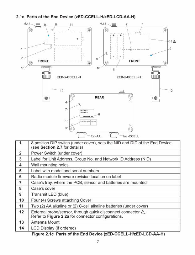
2.1c Parts of the End Device (zED-CCELL-H/zED-LCD-AA-H)
1 8 position DIP switch (under cover), sets the NID and DID of the End Device (see Section 2.7 for details)
2 Power Switch (under cover)
3 Label for Unit Address, Group No. and Network ID Address (NID)
4 Wall mounting holes
5 Label with model and serial numbers
6 Radio module firmware revision location on label
7 Case’s tray, where the PCB, sensor and batteries are mounted
8 Case’s cover
9 Transmit LED (blue)
10 Four (4) Screws attaching Cover
11 Two (2) AA alkaline or (2) C-cell alkaline batteries (under cover)
12 External probe/sensor, through quick disconnect connector . Refer to Figure 2.2a for connector configurations.
13 Antenna Mount
14 LCD Display (if ordered)
Figure 2.1c Parts of the End Device (zED-CCELL-H/zED-LCD-AA-H)
MODEL #
SERIAL #
#.#
2
9
10
3
6
5 Unit Addr Group Net. Addr
FRONT
REAR
1
13
12
+
-
11
4
7
8
for -AA for -CCELL
zED-x-CCELL-H zED-x-CCELL-H
2
9
10
14
FRONT
113
12
++
- -
11
8
8
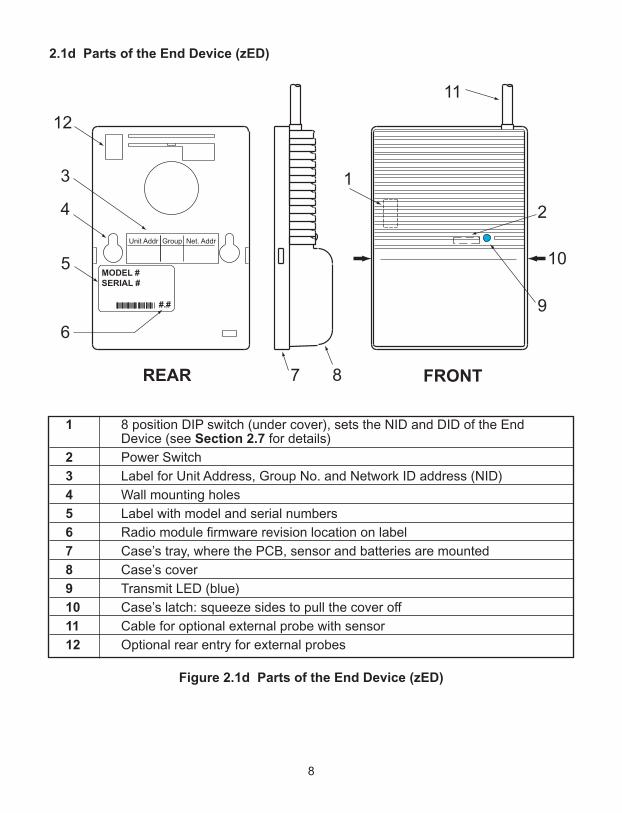
2.1d Parts of the End Device (zED)
1 8 position DIP switch (under cover), sets the NID and DID of the End Device (see Section 2.7 for details)
2 Power Switch
3 Label for Unit Address, Group No. and Network ID address (NID)
4 Wall mounting holes
5 Label with model and serial numbers
6 Radio module firmware revision location on label
7 Case’s tray, where the PCB, sensor and batteries are mounted
8 Case’s cover
9 Transmit LED (blue)
10 Case’s latch: squeeze sides to pull the cover off
11 Cable for optional external probe with sensor
12 Optional rear entry for external probes
Figure 2.1d Parts of the End Device (zED)
FRONTREAR
11
9
2
10
7 8
MODEL #
SERIAL #
#.#
1
4
3
5
6
12
Unit Addr Group Net. Addr
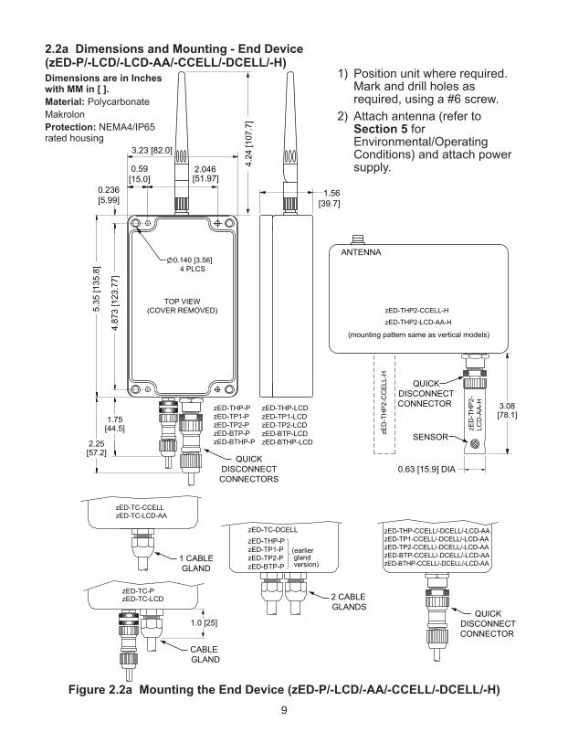
2.2a Dimensions and Mounting - End Device (zED-P/-LCD/-LCD-AA/-CCELL/-DCELL/-H)
Figure 2.2a Mounting the End Device (zED-P/-LCD/-AA/-CCELL/-DCELL/-H)
3.23 [82.0]
2.046[51.97]
1.56[39.7]
0.59[15.0]
0.236[5.99]
5.35
[135
.8]
4.87
3 [1
23.7
7]
0.140 [3.56]4 PLCS
TOP VIEW(COVER REMOVED)
DIMENSIONS ARE ININCHES WITH MM IN [ ].
4.24
[107
.7]
gland
1.0 [25]
2.25[57.2]
1.75[44.5]
QUICKDISCONNECTCONNECTORS
CABLEGLAND
(earlier
version)1 CABLEGLAND
zED-THP-CCELL/-DCELL/-LCD-AAzED-TP1-CCELL/-DCELL/-LCD-AAzED-TP2-CCELL/-DCELL/-LCD-AAzED-BTP-CCELL/-DCELL/-LCD-AAzED-BTHP-CCELL/-DCELL/-LCD-AA
zED-TC-CCELLzED-TC-LCD-AA
2 CABLEGLANDS
QUICKDISCONNECTCONNECTOR
zED-THP2-CCELL-H
zED-THP2-LCD-AA-H
(mounting pattern same as vertical models)
QUICK
SENSOR
DISCONNECTCONNECTOR
ANTENNA
3.08[78.1]
0.63 [15.9] DIA
zED
-TH
P2-
CC
ELL
-H
zED
-TH
P2-
LCD
-AA
-H
9
Dimensions are in Incheswith MM in [ ].
Material: Polycarbonate
Makrolon
Protection: NEMA4/IP65rated housing
1) Position unit where required.Mark and drill holes asrequired, using a #6 screw.
2) Attach antenna (refer toSection 5 forEnvironmental/OperatingConditions) and attach powersupply.

2.2b Dimensions and Mounting - End Device (zED)
Position unit where required. Mark and drill holes as required, using a #6 screw.
Figure 2.2b Mounting the End Device (zED)
2.3 External Sensors/Probes for the End Device
FROM TOP TO BOTTOM:
1) External Industrial Probe ,Temperature / Humidity -THPor
Barometric Pressure /Temperature -BTP, -BTHP
2) External Temperature StickProbe -TP1
3) External Temperature LugMount Probe -TP2
Figure 2.3 External Sensor/Probes
0.94
[23.8]2.54 [64.5]
SIDE AND FRONT VIEWS INSIDE CASE, MOUNTING
2.54 [64.5] REF
0.32 [8.1]
3.6
1 [
91
.8]
3.6
1 [
91
.8]
RE
F
1.8
1 [
45
.9]
Optional
External
Sensor
0.140
[3.56]
2 PLCS
1.90 [48.3]
1010
Material: PBT (Valox)
11
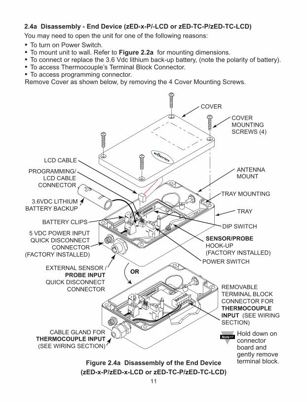
2.4a Disassembly - End Device (zED-x-P/-LCD or zED-TC-P/zED-TC-LCD)
You may need to open the unit for one of the following reasons:
• To turn on Power Switch.• To mount unit to wall. Refer to Figure 2.2a for mounting dimensions.• To connect or replace the 3.6 Vdc lithium back-up battery, (note the polarity of battery).• To access Thermocouple’s Terminal Block Connector.• To access programming connector.Remove Cover as shown below, by removing the 4 Cover Mounting Screws.
Figure 2.4a Disassembly of the End Device
(zED-x-P/zED-x-LCD or zED-TC-P/zED-TC-LCD)
POWER SWITCH
BATTERY CLIPS
TRAY
COVER MOUNTINGSCREWS (4)
ANTENNA
COVER
PROGRAMMING/LCD CABLE
CONNECTOR
8
DIP SWITCH
5 VDC POWER INPUTQUICK DISCONNECT
CONNECTOR(FACTORY INSTALLED)
TRAY MOUNTING
MOUNT
SENSOR/PROBE HOOK-UP(FACTORY INSTALLED)
EXTERNAL SENSOR /PROBE INPUT
QUICK DISCONNECTCONNECTOR
3.6VDC LITHIUMBATTERY BACKUP
LCD CABLE
1
11
8
1
REMOVABLETERMINAL BLOCK CONNECTOR FORTHERMOCOUPLE INPUT (SEE WIRINGSECTION)
CABLE GLAND FOR THERMOCOUPLE INPUT(SEE WIRING SECTION)
6
11
OR
Hold down onconnectorboard andgently removeterminal block.

2.4b Disassembly - End Device (zED-x-LCD-AA or zED-TC-LCD-AA)
You may need to open the unit for one of the following reasons:
• To turn on Power Switch.• To mount unit to wall. Refer to Figure 2.2a for mounting dimensions.• To connect or replace the AA alkaline batteries, (note the polarity of battery).• To access Thermocouple’s Terminal Block Connector.• To access programming connector.Remove Cover as shown below, by removing the 4 Cover Mounting Screws.
Figure 2.4b Disassembly of the End Device
(zED-x-LCD-AA or zED-TC-LCD-AA)
8
1
REMOVABLETERMINAL BLOCK CONNECTOR FORTHERMOCOUPLE INPUT (SEE WIRINGSECTION)CABLE GLAND FOR
THERMOCOUPLE INPUT(SEE WIRING SECTION)
1
6
1
TRAY
COVER MOUNTINGSCREWS (4)
ANTENNA
COVER
8
1
DIP SWITCH AA ALKALINE
BATTERIES
TRAY MOUNTING
MOUNT
1
1
EXTERNAL SENSOR /PROBE INPUT
QUICK DISCONNECTCONNECTOR
OR
BATTERY CLIPS
PROGRAMMING/LCD CABLE
CONNECTOR
LCD CABLE
POWER SWITCH
SENSOR/PROBE HOOK-UP(FACTORY INSTALLED)
12
Hold down onconnectorboard andgently removeterminal block.

2.4c Disassembly - End Device (zED-x-CCELL or zED-TC-CCELL)
You may need to open the unit for one of the following reasons:
• To turn on Power Switch.
• To mount unit to wall. Refer to Figure 2.2a for mounting dimensions.
• To connect or replace the two C-cell alkaline batteries, (note the polarity of batteries).
• To access Thermocouple’s Terminal Block Connector.
• To access programming connector.
Remove Cover as shown below, by removing the 4 Cover Mounting Screws.
Figure 2.4c Disassembly of the End Device (zED-x-CCELL or zED-TC-CCELL)
POWER SWITCH
BATTERY CLIPS
TRAY
COVER MOUNTINGSCREWS (4)
ANTENNA
COVER
PROGRAMMINGCONNECTOR
DIP SWITCH
TRAY MOUNTING
MOUNT
CABLE GLAND FORTHERMOCOUPLE INPUT(SEE WIRING SECTION)
REMOVABLETERMINAL BLOCKCONNECTOR FORTHERMOCOUPLE INPUT(SEE WIRING SECTION)
C-CELLBATTERIES
16
OR
QUICK DISCONNECTCONNECTOR FOR
EXTERNAL SENSOR /PROBE (WIRING IS
FACTORY-INSTALLED)
(FOR -TC MODEL)
13
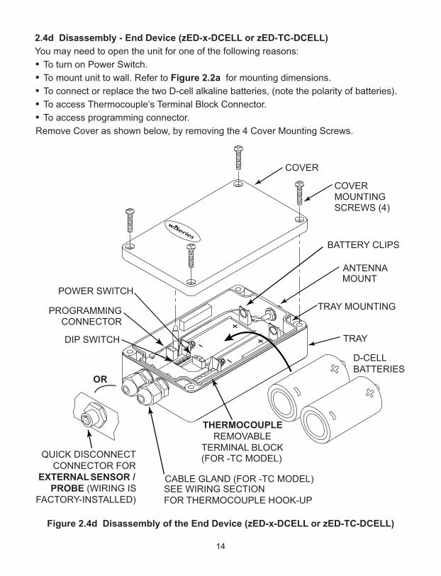
2.4d Disassembly - End Device (zED-x-DCELL or zED-TC-DCELL)
You may need to open the unit for one of the following reasons:
• To turn on Power Switch.
• To mount unit to wall. Refer to Figure 2.2a for mounting dimensions.
• To connect or replace the two D-cell alkaline batteries, (note the polarity of batteries).
• To access Thermocouple’s Terminal Block Connector.
• To access programming connector.
Remove Cover as shown below, by removing the 4 Cover Mounting Screws.
Figure 2.4d Disassembly of the End Device (zED-x-DCELL or zED-TC-DCELL)
POWER SWITCH
BATTERY CLIPS
TRAY
COVER MOUNTINGSCREWS (4)
ANTENNA
COVER
PROGRAMMINGCONNECTOR
DIP SWITCH
TRAY MOUNTING
MOUNT
CABLE GLAND (FOR -TC MODEL)SEE WIRING SECTION FOR THERMOCOUPLE HOOK-UP
QUICK DISCONNECTCONNECTOR FOR
EXTERNAL SENSOR /PROBE (WIRING IS
FACTORY-INSTALLED)
THERMOCOUPLEREMOVABLE
TERMINAL BLOCK
D-CELLBATTERIES
OR
(FOR -TC MODEL)
14
15
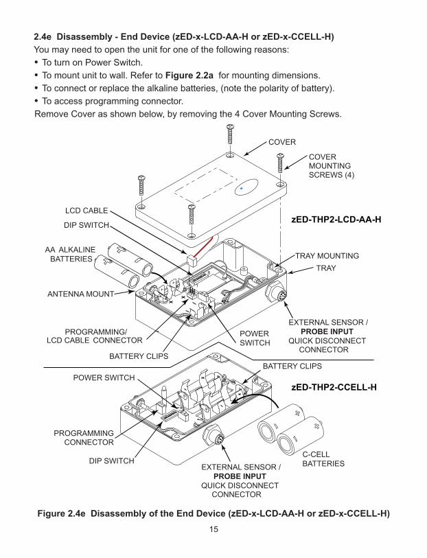
2.4e Disassembly - End Device (zED-x-LCD-AA-H or zED-x-CCELL-H)
You may need to open the unit for one of the following reasons:
• To turn on Power Switch.
• To mount unit to wall. Refer to Figure 2.2a for mounting dimensions.
• To connect or replace the alkaline batteries, (note the polarity of battery).
• To access programming connector.
Remove Cover as shown below, by removing the 4 Cover Mounting Screws.
Figure 2.4e Disassembly of the End Device (zED-x-LCD-AA-H or zED-x-CCELL-H)
TRAY
COVER MOUNTINGSCREWS (4)
COVER
8
1
DIP SWITCH
AA ALKALINEBATTERIES
TRAY MOUNTING
ANTENNA MOUNT
1
1
EXTERNAL SENSOR /PROBE INPUT
QUICK DISCONNECTCONNECTOR
BATTERY CLIPS
PROGRAMMING/LCD CABLE CONNECTOR
LCD CABLE
POWERSWITCH
POWER SWITCHBATTERY CLIPS
PROGRAMMINGCONNECTOR
DIP SWITCH C-CELLBATTERIES EXTERNAL SENSOR /
PROBE INPUTQUICK DISCONNECT
CONNECTOR
zED-THP2-LCD-AA-H
zED-THP2-CCELL-H

2.4f Disassembly - End Device (zED)
You may need to open the unit for one of the following reasons:
• To turn on Power Switch.
• To mount unit to wall. Refer to Figure 2.2b for mounting dimensions.
• To connect or replace the two 1.5 Vdc AA alkaline batteries, (note the polarity ofbatteries).
• To access programming connector.
Remove Cover as shown below, by pressing sides of cover to release latches.
Figure 2.4f Disassembly of the End Device (zED)
COVER
LATCH
SENSORBOARD
EXTERNAL SENSOR/PROBE
TRAY
POWER SWITCHBATTERY CLIPS
LATCH
DIP SWITCH
MOUNTING SCREW
PROGRAMMINGCONNECTOR
8
1
AA ALKALINEBATTERIES
16

2.5 Parts of the Coordinator
Figure 2.5 Parts of the Coordinator
1 Wall mounting bracket clip holes (3 places)
2 Label with model and serial numbers
3 Coordinator’s firmware revision on label
4 8 position DIP switch, from which the last 3 positions are used to assign the NID,network ID number (see Section 2.7 for details)
5 Ethernet: RJ45 interface for 10BASE-T connection.
6 Case’s tray, where the PCB is mounted
7 4 position DIP switch, sets the DHCP and Factory Defaults
8 Coordinator’s radio module firmware revision on label
9 Label with default IP address, remove and then write your IP address, in the space provided
10 Label with MAC address (in hex code)
11 Wall mounting bracket
12 Case’s cover mounting screw (2 places)
13 Label for Network ID address (NID)
14 Power supply: Plus (+) power supply wire connection inside the plug; Minus (-) power supply wire connection outside the plug
15 Reset button: Used for power reseting the Ethernet board
16 Case’s cover
17

2.5 Parts of the Coordinator (continued)
17 Diagnostics LED: (Yellow and Green) Diagnostics: at boot-up they light up for2 seconds, then turn off; DHCP: if DHCP is enabled, they blink and stay solid periodically Network Link LED: (Green) Solid: Indicates good network link.Activity LED: (Red) Blinking: Indicates network activities (receiving or sending packets).
18 Receive LED (blue) while blinking, the Coordinator looks for the clearest channel to communicate. Once it finds that channel, the light will change to solid.
19 Antenna connector
20 Power LED: (Green) Solid: Indicates Power-ON
2.6 Dimensions and Mounting - Coordinator
Position unit where required. Mark and drill the two screw holes. Once the bracket ismounted to the wall: align back of unit over the three bracket clips, when engaged, slidedownward, the unit will snap in place.
Version A: Metal Enclosure Version B: New Plastic EnclosureFigure 2.6 Mounting the Coordinator
Attach antenna (refer to Section 5 for Environmental/Operating Conditions) and attachpower supply.
If unit is to be mounted on a flat surface, you may take the bottom rubber feet offthe unit.
66.0 [2.60]
REF33.0 [1.30]
93.1
[3.67]
REF
38.1
[1.50]
27.3
[1.07]
Bracket Clips (3)
Drill 2 HOLES
3.6 [ 0.14]
Use #6 Screws (Provided)
to Mount the Bracket
EthernetEthernet
90.3
[3.56]
REF
32.4
[1.27]
11.7 [0.46] 38.1[1.50]
61.6 [2.42] REF
Bracket Clips (3)
Bracket Snap
Drill 2 HOLES
3.17 [ 0.125]
Use #4 Screws (Provided)
to Mount the Bracket
18
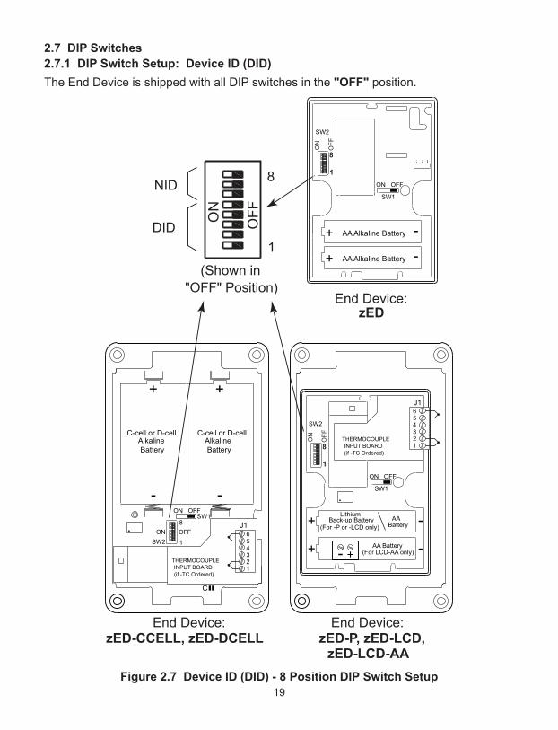
2.7 DIP Switches
2.7.1 DIP Switch Setup: Device ID (DID)
The End Device is shipped with all DIP switches in the "OFF" position.
Figure 2.7 Device ID (DID) - 8 Position DIP Switch Setup
ON
OFF
1
8
OFFON
1
8
End Device: End Device:
End Device: zED
(Shown in "OFF" Position)
DID
NID
654321
THERMOCOUPLEINPUT BOARD(if -TC Ordered)
C
654321
J1
+
-ON OFF
SW1
1
8
SW2ON OFF
THERMOCOUPLEINPUT BOARD(if -TC Ordered)
SW2
ON OFF
SW1
ON
OFF
1
8
SW2
ON OFF
SW1
J1
AA Alkaline Battery+ -
AA Alkaline Battery+ -
Alkaline Battery
Alkaline Battery
+
-
zED-CCELL, zED-DCELL zED-P, zED-LCD,zED-LCD-AA
C-cell or D-cell C-cell or D-cell
Lithium
(For -P or -LCD only)AA
Battery+ -
+ -(For LCD-AA only) AA Battery
+-
Back-up Battery
19
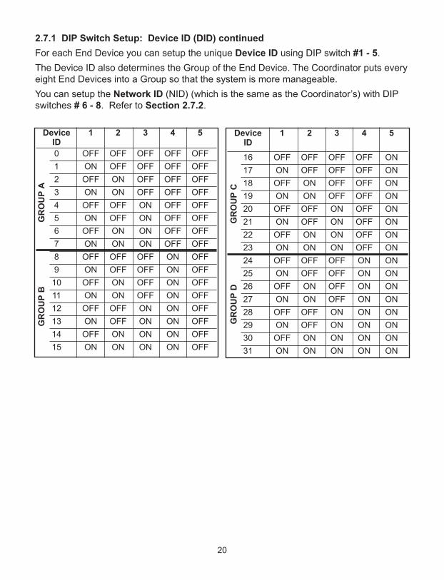
2.7.1 DIP Switch Setup: Device ID (DID) continued
For each End Device you can setup the unique Device ID using DIP switch #1 - 5.
The Device ID also determines the Group of the End Device. The Coordinator puts everyeight End Devices into a Group so that the system is more manageable.
You can setup the Network ID (NID) (which is the same as the Coordinator’s) with DIPswitches # 6 - 8. Refer to Section 2.7.2.
20
Device 1 2 3 4 5ID
16 OFF OFF OFF OFF ON
17 ON OFF OFF OFF ON
18 OFF ON OFF OFF ON
19 ON ON OFF OFF ON
20 OFF OFF ON OFF ON
21 ON OFF ON OFF ON
22 OFF ON ON OFF ON
23 ON ON ON OFF ON
24 OFF OFF OFF ON ON
25 ON OFF OFF ON ON
26 OFF ON OFF ON ON
27 ON ON OFF ON ON
28 OFF OFF ON ON ON
29 ON OFF ON ON ON
30 OFF ON ON ON ON
31 ON ON ON ON ON
Device 1 2 3 4 5ID
0 OFF OFF OFF OFF OFF
1 ON OFF OFF OFF OFF
2 OFF ON OFF OFF OFF
3 ON ON OFF OFF OFF
4 OFF OFF ON OFF OFF
5 ON OFF ON OFF OFF
6 OFF ON ON OFF OFF
7 ON ON ON OFF OFF
8 OFF OFF OFF ON OFF
9 ON OFF OFF ON OFF
10 OFF ON OFF ON OFF
11 ON ON OFF ON OFF
12 OFF OFF ON ON OFF
13 ON OFF ON ON OFF
14 OFF ON ON ON OFF
15 ON ON ON ON OFF
GR
OU
P A
GR
OU
P D
GR
OU
P C
GR
OU
P B
21
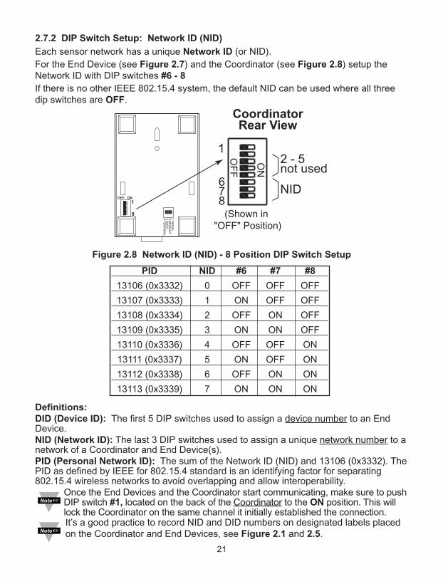
2.7.2 DIP Switch Setup: Network ID (NID)
Each sensor network has a unique Network ID (or NID).
For the End Device (see Figure 2.7) and the Coordinator (see Figure 2.8) setup theNetwork ID with DIP switches #6 - 8
If there is no other IEEE 802.15.4 system, the default NID can be used where all threedip switches are OFF.
Figure 2.8 Network ID (NID) - 8 Position DIP Switch Setup
Definitions:DID (Device ID): The first 5 DIP switches used to assign a device number to an EndDevice.NID (Network ID): The last 3 DIP switches used to assign a unique network number to anetwork of a Coordinator and End Device(s). PID (Personal Network ID): The sum of the Network ID (NID) and 13106 (0x3332). ThePID as defined by IEEE for 802.15.4 standard is an identifying factor for separating802.15.4 wireless networks to avoid overlapping and allow interoperability.
Once the End Devices and the Coordinator start communicating, make sure to pushDIP switch #1, located on the back of the Coordinator to the ON position. This willlock the Coordinator on the same channel it initially established the connection. It’s a good practice to record NID and DID numbers on designated labels placedon the Coordinator and End Devices, see Figure 2.1 and 2.5.
OFF ON
1
8
1 S
ER
IAL
2 D
EF
AU
LT
3 D
HC
P
4 T
ER
MIN
AL
ON
OF
F
1
8
OFF
ON
1
8
End Device:
zED with cover removed
zED-x-P with cover removed
and bottom tray not shown
Coordinator
Rear View
(Shown in
"OFF" Position)
DID
NID
OF
F
ON
678
1
(Shown in
"OFF" Position)
2 - 5 not used
NID
PID NID #6 #7 #8
13106 (0x3332) 0 OFF OFF OFF
13107 (0x3333) 1 ON OFF OFF
13108 (0x3334) 2 OFF ON OFF
13109 (0x3335) 3 ON ON OFF
13110 (0x3336) 4 OFF OFF ON
13111 (0x3337) 5 ON OFF ON
13112 (0x3338) 6 OFF ON ON
13113 (0x3339) 7 ON ON ON
CoordinatorRear View
22
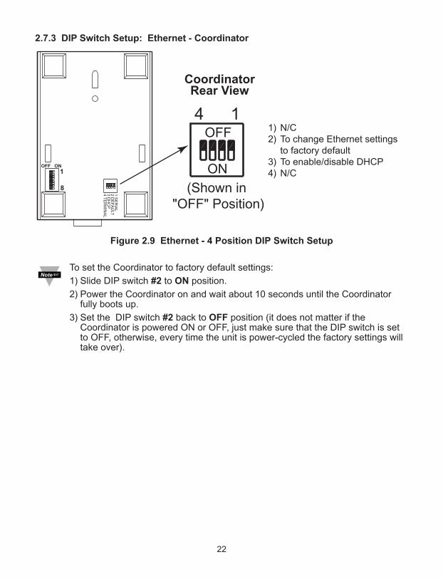
2.7.3 DIP Switch Setup: Ethernet - Coordinator
Figure 2.9 Ethernet - 4 Position DIP Switch Setup
To set the Coordinator to factory default settings:
1) Slide DIP switch #2 to ON position.
2) Power the Coordinator on and wait about 10 seconds until the Coordinatorfully boots up.
3) Set the DIP switch #2 back to OFF position (it does not matter if theCoordinator is powered ON or OFF, just make sure that the DIP switch is setto OFF, otherwise, every time the unit is power-cycled the factory settings willtake over).
OFF ON
1
8
1 S
ER
IAL
2 D
EF
AU
LT
3 D
HC
P4
TE
RM
INA
L
Coordinator
Rear View
OFF
ON
14
(Shown in
"OFF" Position)
1) N/C2) To change Ethernet settings
to factory default 3) To enable/disable DHCP4) N/C
CoordinatorRear View
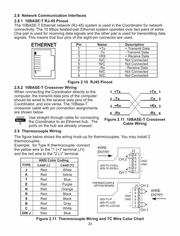
2.8 Network Communication Interfaces
2.8.1 10BASE-T RJ-45 PinoutThe 10BASE-T Ethernet network (RJ-45) system is used in the Coordinator for networkconnectivity. The 10 Mbps twisted-pair Ethernet system operates over two pairs of wires.One pair is used for receiving data signals and the other pair is used for transmitting datasignals. This means that four pins of the eight-pin connector are used.
Figure 2.10 RJ45 Pinout
2.8.2 10BASE-T Crossover WiringWhen connecting the Coordinator directly to thecomputer, the transmit data pins of the computershould be wired to the receive data pins of theCoordinator, and vice versa. The 10Base-Tcrossover cable with pin connection assignmentsare shown below.
Use straight through cable for connectingthe Coordinator to an Ethernet hub. Theports on the hub are already crossed.
2.9 Thermocouple Wiring
The figure below shows the wiring hook-up for thermocouples. You may install 2thermocouples.Example: for Type K thermocouple, connectthe yellow wire to the "1 (+)" terminal (J1)and the red wire to the "2 (-)" terminal.
Figure 2.11 Thermocouple Wiring and TC Wire Color Chart
23
654321
zED-TC-PzED-TC-LCDzED-TC-LCD-AA
654321
J1
zED-TC-CCELLzED-TC-DCELL
THERMOCOUPLEOPTION BOARD J1
-+GNDGND-+
-+
GNDGND
-+
CH 1
CH 2
CH 1
CH 2WIREENTRY
WIREENTRY
ANSI Color Coding
TYPE Lead (-) Lead (+)
J Red White
K Red Yellow
T Red Blue
E Red Purple
N Red Orange
R Red Black
S Red Black
B Red Gray
C Red White
DIN J Red Blue
Pin Name Description1 +Tx + Transmit Data2 -Tx - Transmit Data3 +RX + Receive Data4 N/C Not Connected5 N/C Not Connected6 -Rx - Receive Data7 N/C Not Connected8 N/C Not Connected
Figure 2.11 10BASE-T CrossoverCable Wiring
PART 3
NeTWoRk coNFIGURATIoN
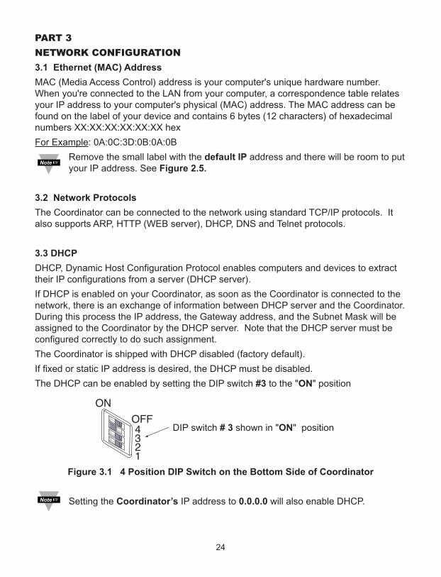
3.1 Ethernet (MAC) Address
MAC (Media Access Control) address is your computer's unique hardware number.When you're connected to the LAN from your computer, a correspondence table relatesyour IP address to your computer's physical (MAC) address. The MAC address can befound on the label of your device and contains 6 bytes (12 characters) of hexadecimalnumbers XX:XX:XX:XX:XX:XX hex
For Example: 0A:0C:3D:0B:0A:0B
Remove the small label with the default IP address and there will be room to putyour IP address. See Figure 2.5.
3.2 Network Protocols
The Coordinator can be connected to the network using standard TCP/IP protocols. Italso supports ARP, HTTP (WEB server), DHCP, DNS and Telnet protocols.
3.3 DHCP
DHCP, Dynamic Host Configuration Protocol enables computers and devices to extracttheir IP configurations from a server (DHCP server).
If DHCP is enabled on your Coordinator, as soon as the Coordinator is connected to thenetwork, there is an exchange of information between DHCP server and the Coordinator.During this process the IP address, the Gateway address, and the Subnet Mask will beassigned to the Coordinator by the DHCP server. Note that the DHCP server must beconfigured correctly to do such assignment.
The Coordinator is shipped with DHCP disabled (factory default).
If fixed or static IP address is desired, the DHCP must be disabled.
The DHCP can be enabled by setting the DIP switch #3 to the "ON" position
DIP switch # 3 shown in "ON" position
Figure 3.1 4 Position DIP Switch on the Bottom Side of Coordinator
Setting the Coordinator’s IP address to 0.0.0.0 will also enable DHCP.
OFF
ON
4 3 2 1
OFF
ON
4 3 2 1
24
25
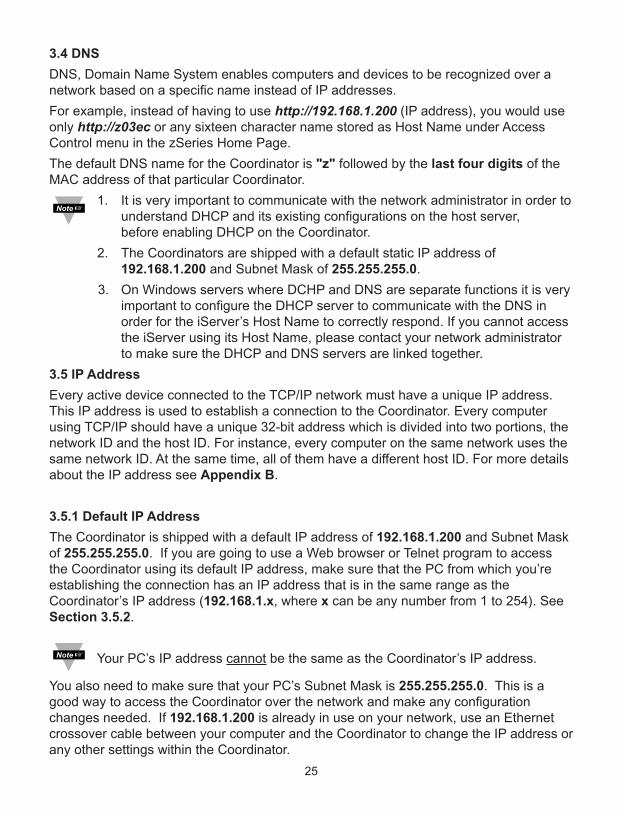
3.4 DNS
DNS, Domain Name System enables computers and devices to be recognized over anetwork based on a specific name instead of IP addresses.
For example, instead of having to use http://192.168.1.200 (IP address), you would useonly http://z03ec or any sixteen character name stored as Host Name under AccessControl menu in the zSeries Home Page.
The default DNS name for the Coordinator is "z" followed by the last four digits of theMAC address of that particular Coordinator.
1. It is very important to communicate with the network administrator in order tounderstand DHCP and its existing configurations on the host server, before enabling DHCP on the Coordinator.
2. The Coordinators are shipped with a default static IP address of192.168.1.200 and Subnet Mask of 255.255.255.0.
3. On Windows servers where DCHP and DNS are separate functions it is veryimportant to configure the DHCP server to communicate with the DNS inorder for the iServer’s Host Name to correctly respond. If you cannot accessthe iServer using its Host Name, please contact your network administratorto make sure the DHCP and DNS servers are linked together.
3.5 IP Address
Every active device connected to the TCP/IP network must have a unique IP address.This IP address is used to establish a connection to the Coordinator. Every computerusing TCP/IP should have a unique 32-bit address which is divided into two portions, thenetwork ID and the host ID. For instance, every computer on the same network uses thesame network ID. At the same time, all of them have a different host ID. For more detailsabout the IP address see Appendix B.
3.5.1 Default IP Address
The Coordinator is shipped with a default IP address of 192.168.1.200 and Subnet Maskof 255.255.255.0. If you are going to use a Web browser or Telnet program to accessthe Coordinator using its default IP address, make sure that the PC from which you’reestablishing the connection has an IP address that is in the same range as theCoordinator’s IP address (192.168.1.x, where x can be any number from 1 to 254). SeeSection 3.5.2.
Your PC’s IP address cannot be the same as the Coordinator’s IP address.
You also need to make sure that your PC’s Subnet Mask is 255.255.255.0. This is agood way to access the Coordinator over the network and make any configurationchanges needed. If 192.168.1.200 is already in use on your network, use an Ethernetcrossover cable between your computer and the Coordinator to change the IP address orany other settings within the Coordinator.
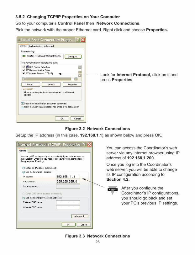
3.5.2 Changing TCP/IP Properties on Your Computer
Go to your computer’s Control Panel then Network Connections.
Pick the network with the proper Ethernet card. Right click and choose Properties.
Figure 3.2 Network Connections
Setup the IP address (in this case, 192.168.1.1) as shown below and press OK.
Figure 3.3 Network Connections
26
Look for Internet Protocol, click on it andpress Properties
You can access the Coordinator’s webserver via any internet browser using IPaddress of 192.168.1.200.
Once you log into the Coordinator’sweb server, you will be able to changeits IP configuration according toSection 4.2.
After you configure theCoordinator’s IP configurations,you should go back and setyour PC’s previous IP settings.

PART 4
oPeRATIoNS
This Coordinator can be used and configured in several ways, depending on user’spreference and network setup. It can be configured using a Web browser, like InternetExplorer. It can also be configured using the iConnect Configuration Software.
If DHCP and DNS servers are configured to exchange information, the connection will bevery simple. All you need to do is to enable DHCP on the Coordinator (see Section 3.3)and use a straight through network cable to connect the Coordinator to an Ethernet hubor switch and power it up. Now, you can use the Coordinator’s default Host (Domain)Name, which is zxxxx (where xxxx are the last four characters of its MAC address) toaccess the Coordinator’s Web Server.
If DHCP is not the preferred method, you can configure your PC’s network connection(see Section 3.5.2 for more details) with an IP address of 192.168.1.x that is in the samerange as the Coordinator’s default IP address (192.168.1.200) and connect to theCoordinator using a cross-over network cable between your PC’s network port and theCoordinator.
After you’re done with configuring the Coordinator, you can set your PC’s networkconnection back to its original settings.
On your computer, from the MS-DOS Prompt window type "ping 192.168.1.200” andpress Enter. If DHCP and DNS servers are used type "ping zxxxx", where xxxx are thelast four digits of the Coordinator’s MAC address, located on the back of the device. Youshould get a reply as shown in Figure 4.1.
4.0 Testing the Connection
Figure 4.1 Pinging the Coordinator from MS-DOS Prompt
This proves that the connection is proper and you can get into configuration or run modeusing the Telnet or Web browser.
27
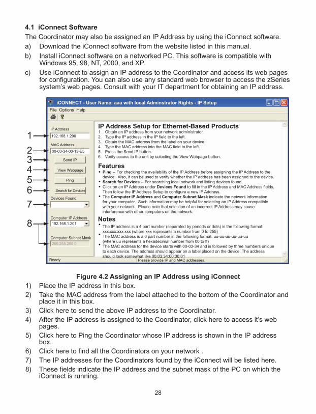
4.1 iConnect Software
The Coordinator may also be assigned an IP Address by using the iConnect software.
a) Download the iConnect software from the website listed in this manual.
b) Install iConnect software on a networked PC. This software is compatible withWindows 95, 98, NT, 2000, and XP.
c) Use iConnect to assign an IP address to the Coordinator and access its web pagesfor configuration. You can also use any standard web browser to access the zSeriessystem’s web pages. Consult with your IT department for obtaining an IP address.
Figure 4.2 Assigning an IP Address using iConnect
1) Place the IP address in this box.
2) Take the MAC address from the label attached to the bottom of the Coordinator andplace it in this box.
3) Click here to send the above IP address to the Coordinator.
4) After the IP address is assigned to the Coordinator, click here to access it’s webpages.
5) Click here to Ping the Coordinator whose IP address is shown in the IP addressbox.
6) Click here to find all the Coordinators on your network .
7) The IP addresses for the Coordinators found by the iConnect will be listed here.
8) These fields indicate the IP address and the subnet mask of the PC on which theiConnect is running.
28
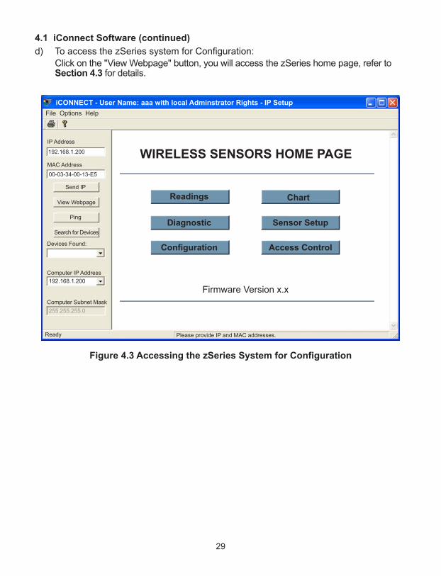
4.1 iConnect Software (continued)
d) To access the zSeries system for Configuration:
Click on the "View Webpage" button, you will access the zSeries home page, refer toSection 4.3 for details.
Figure 4.3 Accessing the zSeries System for Configuration
29
30
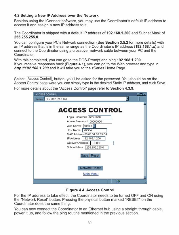
4.2 Setting a New IP Address over the Network
Besides using the iConnect software, you may use the Coordinator’s default IP address toaccess it and assign a new IP address to it.
The Coordinator is shipped with a default IP address of 192.168.1.200 and Subnet Mask of255.255.255.0.
You can configure your PC’s Network connection (See Section 3.5.2 for more details) withan IP address that is in the same range as the Coordinator’s IP address (192.168.1.x) andconnect to the Coordinator using a crossover network cable between your PC and theCoordinator.
With this completed, you can go to the DOS-Prompt and ping 192.168.1.200. If you receive responses back (Figure 4.1), you can go to the Web browser and type inhttp://192.168.1.200 and it will take you to the zSeries Home Page.
Select , button, you’ll be asked for the password. You should be on theAccess Control page were you can simply type in the desired Static IP address, and click Save.
For more details about the "Access Control" page refer to Section 4.3.9.
Figure 4.4 Access Control
For the IP address to take effect, the Coordinator needs to be turned OFF and ON usingthe "Network Reset" button. Pressing the physical button marked "RESET" on theCoordinator does the same thing.
You can now connect the Coordinator to an Ethernet hub using a straight through cable,power it up, and follow the ping routine mentioned in the previous section.
Access Control
ACCESS CONTROL
ACCESS CONTROL
http://192.168.1.200Address
Main Menu
Login Password 12345678
Admin Password 00000000
IP Address 192.168.1.200
Gateway Address 0.0.0.0
Subnet Mask 255.255.255.0
MAC Address 00:03:34:00:85:C4
Web Server enable
Host Name z85C4
Save Reset
Network Reset
31
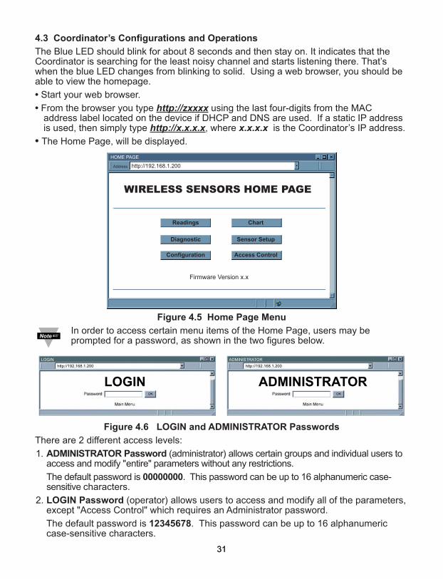
4.3 Coordinator’s Configurations and Operations
The Blue LED should blink for about 8 seconds and then stay on. It indicates that theCoordinator is searching for the least noisy channel and starts listening there. That’swhen the blue LED changes from blinking to solid. Using a web browser, you should beable to view the homepage.
• Start your web browser.
• From the browser you type http://zxxxx using the last four-digits from the MACaddress label located on the device if DHCP and DNS are used. If a static IP address is used, then simply type http://x.x.x.x, where x.x.x.x is the Coordinator’s IP address.
• The Home Page, will be displayed.
Figure 4.5 Home Page Menu
In order to access certain menu items of the Home Page, users may beprompted for a password, as shown in the two figures below.
Figure 4.6 LOGIN and ADMINISTRATOR Passwords
There are 2 different access levels:
1. ADMINISTRATOR Password (administrator) allows certain groups and individual users to access and modify "entire" parameters without any restrictions.
The default password is 00000000. This password can be up to 16 alphanumeric case-sensitive characters.
2. LOGIN Password (operator) allows users to access and modify all of the parameters,except "Access Control" which requires an Administrator password.
The default password is 12345678. This password can be up to 16 alphanumeric case-sensitive characters.
WIRELESS SENSORS HOME PAGE
Firmware Version x.x
HOME PAGE
http://192.168.1.200Address
Readings
Diagnostic
Configuration
Chart
Sensor Setup
Access Control
ADMINISTRATOR
ADMINISTRATOR
LOGIN
LOGIN
http://192.168.1.200 http://192.168.1.200
31

4.3.1 Power Up Device
To verify that an End Device is working before deploying remotely, install batteries andpower it on right next to the Coordinator. When the End Device is powered on, it willsearch for the Coordinator in all 16 channels reserved for IEEE 802.15.4 (channel 11through 26) by sending request packets. While it’s searching, the blue LED on the EndDevice blinks every second. Once the Coordinator responds to the End Device request,the LED will blink only when the End Device sends data to the Coordinator (default isevery 10 seconds). If the Coordinator is not powered on or it’s out of reach, the EndDevice will keep searching until the batteries discharge (e.g. roughly 36 hours for zED).
Once the Coordinator responds back to the End Device it will include its network numberin the response packet called Beacon. At this time the End Device would know what thecorrect Coordinator is (there could be more than one Coordinator responding to the EndDevice’s request packet). The channel on which the Coordinator responds back isautomatically picked to be the clearest among all 16 channels and therefore the EndDevice starts sending data to the Coordinator on that particular channel.
Once the End Devices and the Coordinator start communicating, make sure topush DIP switch #1 located on the back of the Coordinator to ON position. Thiswill lock the Coordinator on the same channel it initially established theconnection.
After the End Device transmits data to the Coordinator, it expects an acknowledgmentpacket back from the Coordinator. If the End Device does not receive anacknowledgment packet back within 50ms, it will go to sleep mode for 2 seconds andthen will transmit the data. This cycle will be repeated for 10 times and if it still does notreceive the acknowledgment packet back, the End Device takes a longer sleep time of 3minutes. After 3 minutes, the End Device retransmits the data every 2 seconds for 4times and each time it waits for 50ms for an acknowledgment. If it still does not receive aresponse back from the Coordinator it will take another 3 minutes of sleep. This lastsequence will continue until the batteries are drained. Through the whole retransmissioncycle explained above the blue LED on the End Device will blink anytime retransmissiontakes place.
The data being retransmitted will automatically gets updated as new readingstake place.
If the communication channel is manually selected in the Coordinator, the EndDevices must be power-cycled in order to establish connection over the newchannel. If it’s not possible to power-cycle the End Devices locally, a remoteoption is available through the Coordinator’s Web server or Telnet console.
When there are two End Devices with the same Device ID, both will betransmitting data every second with their LEDs blinking once a second. TheCoordinator will receive data from both End Devices and will display their dataalternately. On the "Readings", "Chart", and "Diagnostic" pages of theCoordinator’s Web server, the phrase "ID" error code will be placed indicatingthe conflict. Once the problem is resolved, click on the "Reset Sensor" buttonlocated on the Sensors Parameters page to remove the "ID" error code.
In case of power failure/outage during normal operation, the zED-P/-LCD willautomatically switch its power supply from AC adapter to back-up battery.However, power switching may fail if the End Device is on and consumes lots ofenergy. Therefore, "LOST" will be detected, the LED stops blinking periodicallyand the unit must be power cycled manually.
32

33
4.3.2 Get Readings from the End Device
Once you see the End Device’s LED blinking periodically, it means it is sending datawhich will appear on the "Readings" page. To view the data in a chart format, you canuse the "Chart" page.
Click on from the Home Page, the following page will appear. Select the properGroup to view the readings.
Figure 4.7 Select Readings by Groups
In a few seconds the following page will appear, showing updates of the Temperature,Barometric Pressure and Humidity values (depending on your available sensors).
Figure 4.8 Readings
While accessing the "Readings" page, If a blank screen appears without any "javaapplication running" or image of a "Java logo", please verify you have the latestJava Runtime Environment installed and configured according to the Section4.3.3.1. If you do not have Java Runtime Environment, you may download it fromour website or contact the Customer Service Department nearest you.
Readings
READINGS: BY GROUPS
READINGS
http://192.168.1.200Address
Main Menu
Wireless Sensors ID: 0 - 7
Wireless Sensors ID: 8 - 15
Wireless Sensors ID: 16 - 23
Wireless Sensors ID: 24 - 31
Sensor Setup
Group A
Group B
Group C
Group D
After enteringa RefreshTime, makesure to pressEnter on yourkeyboard.
34
4.3.2 Get Readings from the End Device (continued)The "Readings" fields are defined as follows: Title: Coordinator’s name, assigned in "Configuration" page.Name: End Device’s name, assigned in "Sensor Parameters" page.ID: Sensor ID.Sequence: Sequence number [0-255, Lost, ID ].The Sequence number is incremented for each newly received data. Therefore, itindicates if the sensor is transmitting data successfully. This area also will display error messages:
Lost Coordinator has not received data from the sensor.ID More than one sensor is configured with the same Device ID.
Reading Values: The order from left to right is Temperature, Barometric Pressure thenHumidity.
First Reading Temperature reading with temperature unit from the primary sensor.Second Reading Pressure reading or Humidity reading, depending on the primarysensor or the secondary sensor reading.Third Reading Humidity reading, if the End Device is a -BTH version or the secondarysensor reading.Fourth Reading: The secondary sensor reading.
Reading "Open" indicates that no sensing device is detected.
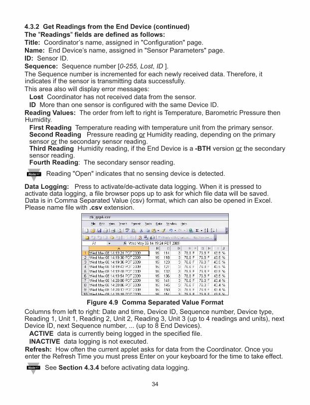
Data Logging: Press to activate/de-activate data logging. When it is pressed toactivate data logging, a file browser pops up to ask for which file data will be saved.Data is in Comma Separated Value (csv) format, which can also be opened in Excel.Please name file with .csv extension.
Figure 4.9 Comma Separated Value Format
Columns from left to right: Date and time, Device ID, Sequence number, Device type,Reading 1, Unit 1, Reading 2, Unit 2, Reading 3, Unit 3 (up to 4 readings and units), nextDevice ID, next Sequence number, ... (up to 8 End Devices).
ACTIVE data is currently being logged in the specified file.INACTIVE data logging is not executed.
Refresh: How often the current applet asks for data from the Coordinator. Once youenter the Refresh Time you must press Enter on your keyboard for the time to take effect.
See Section 4.3.4 before activating data logging.
35
4.3.3 Java Runtime Environment Setup
If your computer does not have Java installed, please download from java.sun.com. Youcan change the Java setting by clicking its icon in Control Panel. To load the applet, youhave to enable the web browser and disable cache.
4.3.3.1 Java Runtime Environment 1.4 Setup instructions
1. Go to your computer's Control Panel. Open the Java Plug-in
2. Select the "Cache" Tab
Un-check the "Enable Caching" box
3. Select the "Proxy" Tab. Follow these Browser Proxy Selection instructionsbelow. (Generally, un-check the box if accessing Coordinator on your localnetwork and check the box for access from your internal network to the internet.)
4. Refresh or restart the webpage.
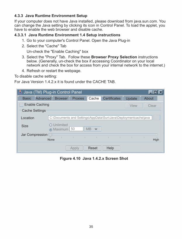
To disable cache setting:
For Java Version 1.4.2.x it is found under the CACHE TAB.
Figure 4.10 Java 1.4.2.x Screen Shot
Java (TM) Plug-in Control Panel
AdvancedBasic ProxiesBrowser CertificatesCache AboutUpdate
Enable Caching
Cache Settings
View Clear
Location
Size
Jar Compression
MBUnlimited
C:\Documents and Settings\AppData\Sun\Java\Deploymentcache\java
None High
Apply Reset Help
Maximum 50
36
4.3.3.2 Java Runtime Environment 1.5 (5.0) Setup instructions
1. Go to your computer's Control Panel. Open the Java Plug-in
2. Click on "Settings" & "View Applets" in the "General" tab.
3. Select the "Settings" button on the General Tab
Un-check the "Enable Caching" box. Then close dialog box to show the GeneralTab again
4. Select the "Network Settings" button on the General Tab.
Proceed to the Browser tab. Follow the Browser Proxy Selection instructionsbelow.You should either select the "Use Browser Settings" option or the "DirectConnection" option depending on the network connections between yourcomputer and the Coordinator. (Generally, select "Direct Connection" if accessingCoordinator on your local network and select "Use Browser Settings" option foraccess from your internal network to the internet.)
5. Refresh or restart the webpage.
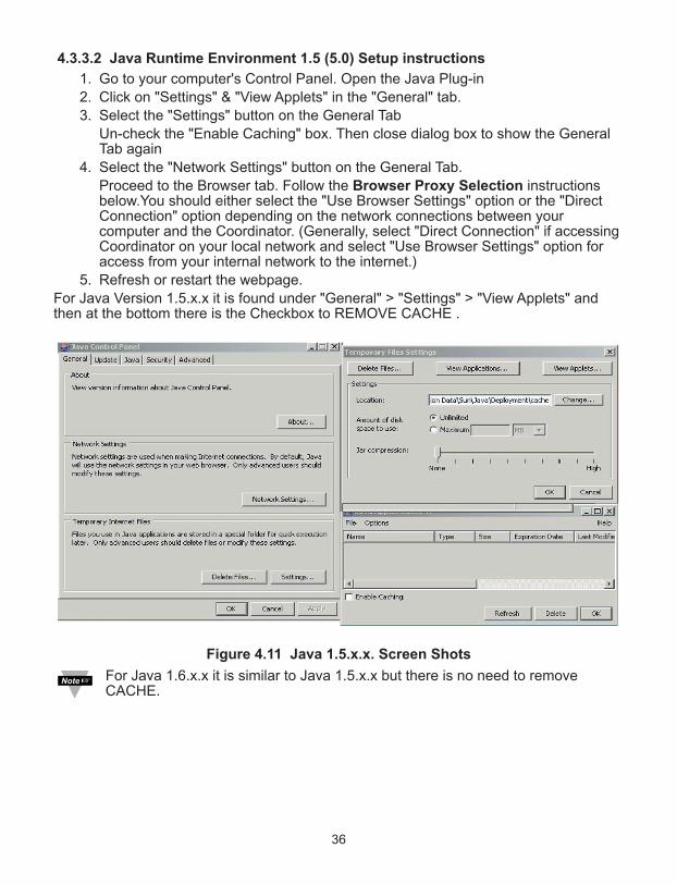
For Java Version 1.5.x.x it is found under "General" > "Settings" > "View Applets" andthen at the bottom there is the Checkbox to REMOVE CACHE .
Figure 4.11 Java 1.5.x.x. Screen Shots
For Java 1.6.x.x it is similar to Java 1.5.x.x but there is no need to removeCACHE.

4.3.3.3 Browser Proxy Selection
Accessing Coordinators within your internal network
• Usually when the computer and Coordinators are on an internal network, you will notuse Proxy server access.
• You should un-check the "Use Browser Settings" option on the "Proxy" tab.
Accessing Coordinators units using the internet
• Often the web browser will use Proxy server access to the internet. In such cases,the default Java runtime settings on the "Proxy" tab should suffice. The defaultsetting is the "Use Browser Settings" option.
• If the default proxy setting doesn't work, then you may have a situation where theproxy settings of the web browser are incorrect.
Diagnostics:
If the web page of the zSeries system appears, then the HTTP Proxy is working fine.
If the data isn't updated on the zSeries system upon selecting the "Readings" web page,there may be a problem with access through a winsock proxy server. In such cases yournetwork administrator will need to provide the winsock proxy server and port #s. (TheTCP ports the Coordinator uses for Java applets are 1000 and 1001).
These values should be entered into the Socks line on the "Proxy" tab (of the JavaPlugin control panel) or into the "connections" tab on the View,Internet Options dialogand make sure that the Proxy tab shows that the "Use Browser Settings" option is notselected (i.e. when you specify proxy connections in the Java Plugin control panel).
Accessing Coordinators units over Peer-to-Peer network
A simple peer-to-peer network is setup by disconnecting from the main network (as userswill often do when trying to do initial setup of the zSeries system) and then connectingthe Coordinator to another computer using an ethernet hub, an ethernet switch, or aCross-over cable connection.
Often when using a peer-to-peer network, the Java plugin and the web browser (such asInternet Explorer) have internet connections configured to connect through proxyservers. In such case, you will need to simply assign the final IP address on this peer topeer network and then view the Wireless System’s charts after connecting theCoordinator into the regular network. Otherwise you can disable the Java plug-in's "UseBrowser Settings" temporarily and then reconfigure the Java plug-in settings for regularnetwork access after testing the Wireless System’s chart access on your peer-to-peernetwork.
The "Use Browser Settings" should not be selected. And the HTTP and Socks proxyentries should be blank. Also, setup the internet browser so that proxy servers are disabled.
Java and the Java Coffee Cup Logo are trademarks or registered trademarks of Sun Microsystems, Inc. in the U.S. and other countries."
37
38
4.3.4 Java Policy
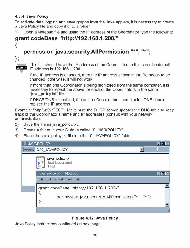
To activate data logging and save graphs from the Java applets, it is necessary to createa Java Policy file and copy it onto a folder.
1) Open a Notepad file and using the IP address of the Coordinator type the following:
grant codeBase "http://192.168.1.200/"
permission java.security.AllPermission "*", "*";;
This file should have the IP address of the Coordinator; in this case the defaultIP address is 192.168.1.200.
If the IP address is changed, then the IP address shown in the file needs to bechanged; otherwise, it will not work.
If more than one Coordinator is being monitored from the same computer, it isnecessary to repeat the above for each of the Coordinators in the same"java_policy.txt" file.
If DHCP/DNS is enabled, the unique Coordinator’s name using DNS shouldreplace the IP address.
Example: "http:\\zSvrTEST". Make sure the DHCP server updates the DNS table to keeptrack of the Coordinator’s name and IP addresses (consult with your networkadministrator).
2) Save the file as java_policy.txt.
3) Create a folder in your C: drive called "0_JAVAPOLICY".
4) Place the java_policy.txt file into the "0_JAVAPOLICY" folder.
Figure 4.12 Java Policy
Java Policy instructions continued on next page.

39
4.3.4 Java Policy (continued)
5) Change Java Applet’s Runtime Parameters found on the following path:
a. Control Panel --> Java --> Java Control Panel --> Java Tab --> View
b. Inside the box under the Java Runtime Parameters type the following:
-Djava.security.policy=C:\0_JAVAPOLICY\java_policy.txt
If you have multiple Java Runtime Versions listed, add this line to the version
that you are using; if you update your Java, you will need to add this line again.
c. Click OK on the Java Runtime Settings window.
d. Click Apply on the Java Control Panel window and then OK.
6) Close all opened Web browser.
Figure 4.13 Java Policy
The "Data Logging" and "Save Current Graph" buttons in the "Readings","Charts", and "Diagnostic" pages will not be active if the instructions explained inthe above Section 4.3.4 are not followed.
Java Runtime Settings
Control Panel
Java Control Panel
Control PanelAddress
CommentsName
Java Java(TM) Control Panel
General Update Security AdvancedJava
Java Applet Runtime Settings
Runtime settings are used when an applet is executed in the browser.
Java Applet Runtime Settings
Product Name Version Location Java Runtime Parameters
JRE 1.5.0_06 C:\Program Files\java\jre1.5.0_06 -Djava.security.policy=C:\0_JAVAPOLICY\java_policy.txt
OK Cancel
OK Cancel Apply
View...
Add text here
40
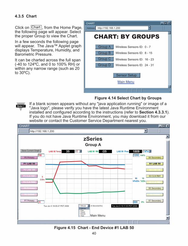
4.3.5 Chart
Click on , from the Home Page,the following page will appear. Selectthe proper Group to view the Chart.
In a few seconds the following pagewill appear. The Java™ Applet graphdisplays Temperature, Humidity, andBarometric Pressure.
It can be charted across the full span(-40 to 124ºC, and 0 to 100% RH) orwithin any narrow range (such as 20to 30ºC).
Figure 4.14 Select Chart by Groups
If a blank screen appears without any "java application running" or image of a"Java logo", please verify you have the latest Java Runtime Environmentinstalled and configured according to the instructions (refer to Section 4.3.3.1).If you do not have Java Runtime Environment, you may download it from ourwebsite or contact the Customer Service Department nearest you.
Figure 4.15 Chart - End Device #1 LAB 50
CHART: BY GROUPS
CHART
http://192.168.1.200Address
Main Menu
Wireless Sensors ID: 0 - 7
Wireless Sensors ID: 8 - 15
Wireless Sensors ID: 16 - 23
Wireless Sensors ID: 24 - 31
Sensor Setup
Group A
Group B
Group C
Group D
Chart
zSeriesGroup A
Main Menu
CHART
(5 Seconds/Div)1 Minute
1 Minute1 Day1 Week1 Month1 Year
0
5
C/Div
50 1200
300
100%
0%
10
%/Div
90
hPa/Div
LAB 50 RH LAB 50 PresC hPa
Tue Jun 5 18:11:55 PDT 2009Tue Jun 5 18:05:27 PDT 2009
http://192.168.1.200
LAB 50 Temp 35 1009/25
P0 Primary
P1 LAB 50
P2 LAB 100
P3 CLN RM1
P4 CLN RM2
P5 Primary
P6 OVEN5
P7 Primary
S0 Secondary
S1 LAB 50
S2 LAB 100
S3 CLN RM1
S4 CLN RM2
S5 Secondary
S6 OVEN5
S7 Secondary
Save Current Graph

41
4.3.5 Chart (continued)
Title: Coordinator’s name, assigned in "Configuration" page.
Save Current Graph: Save the current graph in PNG (Portable Network Graphics)format. The filename has extension .png.
Max/Min Temperature: Maximum and minimum temperature of the current graph.
If a sensor is selected (trend line and sensor name turns bold), its most currenttemperature reading is shown here.
Temperature Unit Drop-down List: Temperature unit to be used, either ºC or ºF.
Max/Min Humidity: Maximum and minimum humidity of the current graph.
If a sensor is selected (trend line and sensor name turns bold), it’s most current humidityreading is shown here.
Max/Min Pressure: Maximum and minimum pressure of the current graph.
If a sensor is selected (trend line and sensor name turns bold), it’s most current pressurereading is shown here.
Reading "Open" indicates that no sensing device is detected.
Pressure Unit Drop-down List: Pressure unit to be used.
P# button (Primary): P# shows the sensor name and controls the primary sensorreadings.
When clicked once,it turns bold, highlights primary sensor trend line and displays currentsensor readings.
when clicked twice, it turns white and the trend line will disappear.
When clicked again, it comes back to normal operation.
Chart Area: Display the trend lines of the sensors.
Range of temperature can be controlled by the upper and lower boxes on the left andrange of pressure can be controlled by the upper and lower boxes on the right.
S# button (Secondary): S# shows the sensor name, displays error messages [Lost/ID]and controls the secondary (external) sensor readings.
When clicked once,it turns bold, highlights secondary sensor trend line and displayscurrent sensor readings.
When clicked twice, it turns white and the trend line will disappear.
When clicked again, it comes back to normal operation.
Applet Start Date and Time: Activates when the "Chart" page opens up.
X-axis Drop-down List: Time scale for the chart.
The chart area can be shown based on 1 min, 1 hour, 1 day, 1 week, 1 month, or 1 yeartime intervals.
Last Update Date and Time: The last date and time when data arrived.

42
4.3.6 Diagnostic
Click on , the following page will appear.
Figure 4.16 Diagnostic
Date and Time: Most recent time when data is received.
Save Current Graph: Save the current graph in PNG format. The filename hasextension .png.
Parameters Logging: Click to activate/deactivate parameters logging. When it isactivated, a file browser screen will allow you to name and save the logging file. The fileis in Comma Separated Value (.csv) format.
ACTIVE – parameters are currently being logged in the specified file.
INACTIVE – parameters logging is not activated.
Coordinator (yellow box): Coordinator is always at the top of the wireless networkhierarchy (star topology).
Sensor: Name of the sensor.
Success Rate: (0-100%), a low success rate indicates a longer data delay, shorterbattery lifetime and high network traffic. Any error messages (LOST, ID, OPEN) will beshown here as well.
Radio Signal Strength: (0-100%), the higher the better.
The blue line and blue triangle (roof) connecting to the Coordinator indicates theradio signal strength. Darker blue means a stronger radio signal.
Dark Blue: between 100% and 79%; Medium Blue; 78% to 11%; Light Blue: 10% to 0%
Update Rate: The time interval the Coordinator received data from the End Device.
Battery Voltage: The total voltage of the batteries in the End Device. Once thevoltage gets to 2.7V, it’s recommended to change the batteries.
The box (house) color indicates battery voltage. Green: >2.7V; Red: <2.7V
Diagnostic
CLN RM1Success 100%Strength 77%Update 10sBattery 3.0V
Lab 100Success 100%Strength 68%Update 10sBattery 2.69V
Lab 50Success 100%Strength 70%Update 10sBattery 2.68V
CLN RM2Success 100%Strength 100%Update 10sPower Adaptor
NODE-5Success 100%Strength 94%Update 10sBattery 3.14V
Fri Jun 05 17:55:14 PDT 2009

4.3.7 Configuration
Click on from the Home Page, the following page will appear.
Figure 4.17 Configuration
Name: Coordinator name [maximum of 16 alphanumeric characters]
Temperature: Unit of temperature readings, [ ºC or ºF ].
Pressure: Unit of pressure readings [ mbar, inHg or mmHg ].
TCP Connections: Number of TCP connections available for data query. If "0" isselected no TCP connection can be made to the indicated port number [ 0 through 5 ].
Port: Port number for TCP connections. [invalid ports: <500, >65536, 1000, 1001 ].
Save: Saves any changes for above settings.
Configuration
CONFIGURATION
CONFIGURATION
http://192.168.1.200Address
Main Menu
Name zSeries
Radio Reset
Temperature C Pressure mbar
TCP Connections 1 Port 02000
Save
Save
Channel 25
PID 13111
Radio Version x.x
Transmission Power 20dBmPlease refer to your local regulations for the allowed
maximum transmission power
43
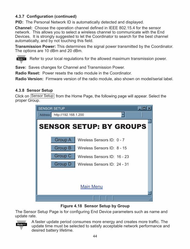
4.3.7 Configuration (continued)
PID: The Personal Network ID is automatically detected and displayed.
Channel: Choose the operation channel defined in IEEE 802.15.4 for the sensornetwork. This allows you to select a wireless channel to communicate with the EndDevices. It is strongly suggested to let the Coordinator to search for the best channelautomatically, and by not touching this field.
Transmission Power: This determines the signal power transmitted by the Coordinator.The options are 10 dBm and 20 dBm.
Refer to your local regulations for the allowed maximum transmission power.
Save: Saves changes for Channel and Transmission Power.
Radio Reset: Power resets the radio module in the Coordinator.
Radio Version: Firmware version of the radio module, also shown on model/serial label.
4.3.8 Sensor Setup
Click on from the Home Page, the following page will appear. Select theproper Group.
Figure 4.18 Sensor Setup by Group
The Sensor Setup Page is for configuring End Device parameters such as name andupdate rate.
A faster update period consumes more energy and creates more traffic. Theupdate time must be selected to satisfy acceptable network performance anddesired battery lifetime.
Sensor Setup
SENSOR SETUP: BY GROUPS
SENSOR SETUP
http://192.168.1.200Address
Main Menu
Wireless Sensors ID: 0 - 7
Wireless Sensors ID: 8 - 15
Wireless Sensors ID: 16 - 23
Wireless Sensors ID: 24 - 31
Sensor Setup
Group A
Group B
Group C
Group D
44
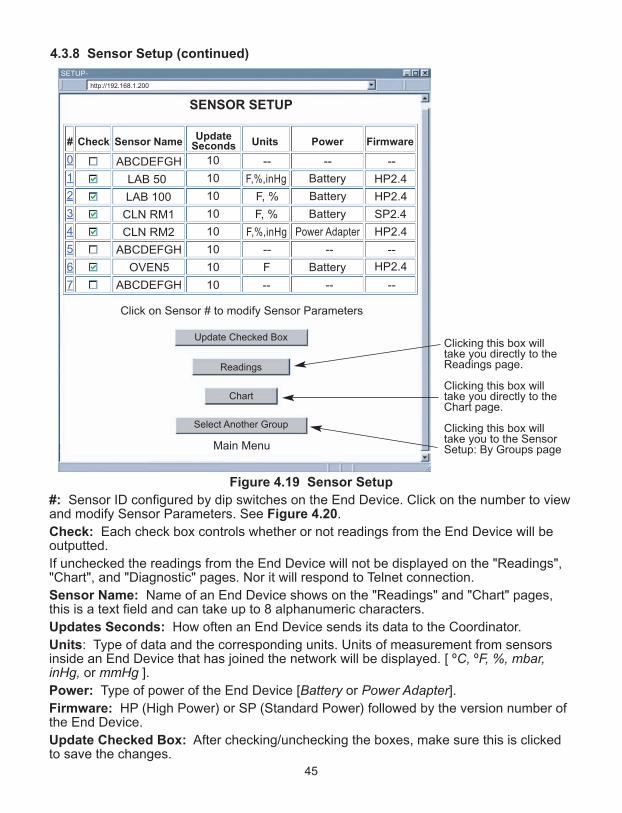
4.3.8 Sensor Setup (continued)
Figure 4.19 Sensor Setup
#: Sensor ID configured by dip switches on the End Device. Click on the number to viewand modify Sensor Parameters. See Figure 4.20.
Check: Each check box controls whether or not readings from the End Device will beoutputted.
If unchecked the readings from the End Device will not be displayed on the "Readings","Chart", and "Diagnostic" pages. Nor it will respond to Telnet connection.
Sensor Name: Name of an End Device shows on the "Readings" and "Chart" pages,this is a text field and can take up to 8 alphanumeric characters.
Updates Seconds: How often an End Device sends its data to the Coordinator.
Units: Type of data and the corresponding units. Units of measurement from sensorsinside an End Device that has joined the network will be displayed. [ ºC, ºF, %, mbar,inHg, or mmHg ].
Power: Type of power of the End Device [Battery or Power Adapter].
Firmware: HP (High Power) or SP (Standard Power) followed by the version number ofthe End Device.
Update Checked Box: After checking/unchecking the boxes, make sure this is clickedto save the changes.
SENSOR SETUP
Main Menu
Click on Sensor # to modify Sensor Parameters
SETUP-
http://192.168.1.200
Update Checked Box
Readings
Chart
Select Another Group
0
1
2
3
4
5
6
7
#
ABCDEFGH
LAB 50
LAB 100
CLN RM1
CLN RM2
ABCDEFGH
OVEN5
ABCDEFGH
Sensor Name
10
10
10
10
10
10
10
10
UpdateSeconds
------
HP2.4
HP2.4
SP2.4
HP2.4
HP2.4
--
--
Firmware
F,%,inHg
F, %
F, %
F,%,inHg
--
F
--
Units
Battery
Battery
Battery
Power Adapter
--
Battery
--
PowerCheck
45
Clicking this box willtake you directly to theReadings page.
Clicking this box willtake you directly to theChart page.
Clicking this box willtake you to the SensorSetup: By Groups page

46
4.3.8 Sensor Setup (continued)
Figure 4.20a Sensor Parameters
Sensor Name: Name of this End Device.
Update (seconds): How often this sensor is sending its data to the Coordinator.
For thermocouple input End Device, Continuous should be selected for continuous modeoperation (20 samples/second) see Figure 4.20b. Periodic (1 sample/update).
A faster update period consumes more energy and creates more traffic. Theupdate time must be selected to satisfy acceptable network performance anddesired battery lifetime.
Cold Junction Compensation: This option is only available for thermocouple.
Click on the link to follow instructions to perform cold junction compensation for theselected thermocouple channel. Cold junction compensation will allow you to adjust(calibrate) the thermocouple in reference to 0°C environment. See Figure 4.20b.
Proper TC must be selected before doing cold junction compensation.
TC Type: Select the proper thermocouple type for the channel or you select "disabled"to disable the channel.
SENSOR PARAMETERS
Sensor #1, Group A
SENSOR PARAMETERS
http://192.168.1.200Address
Main Menu
Sensor Name LAB 50
Select Another Group
Identify: INACTIVE
Reset Sensor
Cancel
Update 10
Update Reset Value
(seconds)
Offset1 (xxxx.x) 0
Offset2 (xxxx.x) 0 (% or mbar)
Offset3 (xxxx.x) 0
Offset4 (xxxx.x) 0 (% or mbar)
(C)
(C)
Update rate is closelyrelated to the lifetime ofthe battery.
Since the End Device is in lowpower consumption (sleep mode)when idle, a longer update rate willcause less energy usage andprolong the life of the battery.
On the other hand, a faster updaterate shortens the battery life andresults in a busy network, which willincrease the chance of signalinterference.
As a general rule of thumb,minimum update rate should beproportional to the number ofsensors in the network.

47
4.3.8 Sensor Setup (continued)
Offset: If it is determined that the readings are slightly off, the user can manually assignnumerical values to adjust the readings for temperature (in ºC) , humidity (inpercentage), and barometric pressure (in mbar). The offset value can either be a positiveor a negative number with one decimal point.
Update: Saves changes
Reset Value: Ignores changes and puts previous values back in the fields.
Cancel: Ignores all the changes and goes back to the "Sensor Setup" page.
Reset Sensor: Reset the End Device readings and status. If the End Device is not onthe network, the data will be cleared after about 3 minutes. Otherwise, the End Devicewill reset itself and re-join the network after a minute.
Identify: INACTIVE: End device is in running mode and sending data to the Coordinatorperiodically. ACTIVE: End device is in identify mode and it keeps its blue LED on solidso that operator can identify the corresponding sensor easily.
Once you click on the “Identity” button (“Active” Status) to locate your EndDevice you need to make sure to click on the button again to make it “Inactive”;otherwise the blue LED will stay solid until the battery is discharged.
Select Another Group: Go back to the group selection page to setup sensors.
Figure 4.20b Sensor Parameters for Thermocouple Option
SENSOR PARAMETERS
Sensor #6, Group A
SENSOR PARAMETERS
http://192.168.1.200Address
Main Menu
Sensor Name OVEN5
Select Another Group
Identify: INACTIVE
Reset Sensor
Cancel
Update Periodic 10
Update Reset Value
(seconds)
Offset1 (xxxx.x) 0
Offset3 (xxxx.x) 0
TC type K type
TC type K type
Cold Junction Compensation for Ch1
Cold Junction Compensation for Ch2
(C)
(C)
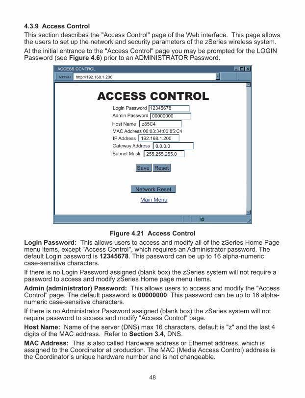
48
4.3.9 Access Control
This section describes the "Access Control" page of the Web interface. This page allowsthe users to set up the network and security parameters of the zSeries wireless system.
At the initial entrance to the "Access Control" page you may be prompted for the LOGINPassword (see Figure 4.6) prior to an ADMINISTRATOR Password.
Figure 4.21 Access Control
Login Password: This allows users to access and modify all of the zSeries Home Pagemenu items, except "Access Control", which requires an Administrator password. Thedefault Login password is 12345678. This password can be up to 16 alpha-numericcase-sensitive characters.
If there is no Login Password assigned (blank box) the zSeries system will not require apassword to access and modify zSeries Home page menu items.
Admin (administrator) Password: This allows users to access and modify the "AccessControl" page. The default password is 00000000. This password can be up to 16 alpha-numeric case-sensitive characters.
If there is no Administrator Password assigned (blank box) the zSeries system will notrequire password to access and modify "Access Control" page.
Host Name: Name of the server (DNS) max 16 characters, default is "z" and the last 4digits of the MAC address. Refer to Section 3.4, DNS.
MAC Address: This is also called Hardware address or Ethernet address, which isassigned to the Coordinator at production. The MAC (Media Access Control) address isthe Coordinator’s unique hardware number and is not changeable.
ACCESS CONTROL
ACCESS CONTROL
http://192.168.1.200Address
Main Menu
Login Password 12345678
Admin Password 00000000
IP Address 192.168.1.200
Gateway Address 0.0.0.0
Subnet Mask 255.255.255.0
MAC Address 00:03:34:00:85:C4
Host Name z85C4
Save Reset
Network Reset
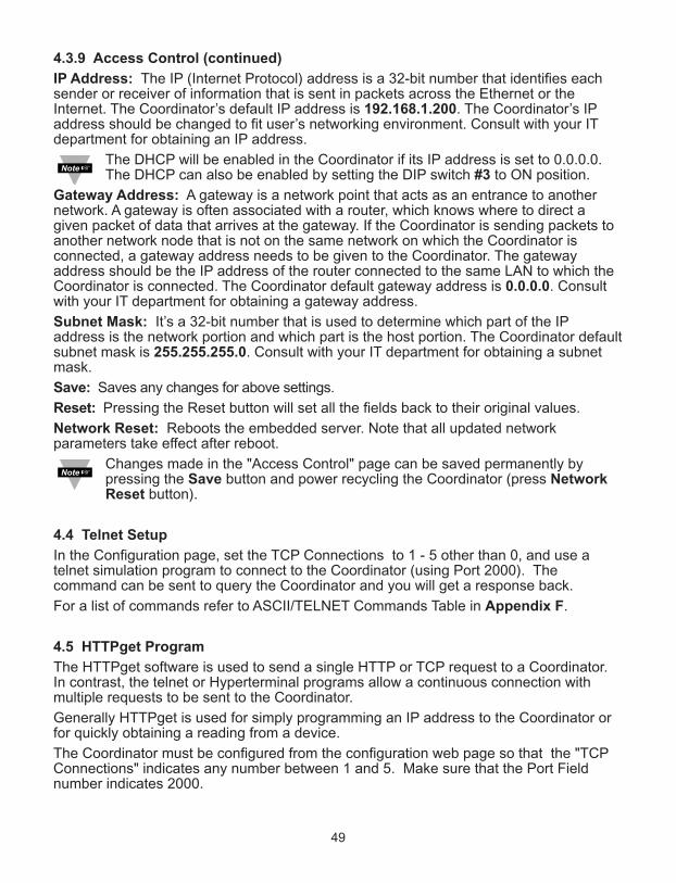
4.3.9 Access Control (continued)
IP Address: The IP (Internet Protocol) address is a 32-bit number that identifies eachsender or receiver of information that is sent in packets across the Ethernet or theInternet. The Coordinator’s default IP address is 192.168.1.200. The Coordinator’s IPaddress should be changed to fit user’s networking environment. Consult with your ITdepartment for obtaining an IP address.
The DHCP will be enabled in the Coordinator if its IP address is set to 0.0.0.0.The DHCP can also be enabled by setting the DIP switch #3 to ON position.
Gateway Address: A gateway is a network point that acts as an entrance to anothernetwork. A gateway is often associated with a router, which knows where to direct agiven packet of data that arrives at the gateway. If the Coordinator is sending packets toanother network node that is not on the same network on which the Coordinator isconnected, a gateway address needs to be given to the Coordinator. The gatewayaddress should be the IP address of the router connected to the same LAN to which theCoordinator is connected. The Coordinator default gateway address is 0.0.0.0. Consultwith your IT department for obtaining a gateway address.
Subnet Mask: It’s a 32-bit number that is used to determine which part of the IPaddress is the network portion and which part is the host portion. The Coordinator defaultsubnet mask is 255.255.255.0. Consult with your IT department for obtaining a subnetmask.
Save: Saves any changes for above settings.
Reset: Pressing the Reset button will set all the fields back to their original values.
Network Reset: Reboots the embedded server. Note that all updated networkparameters take effect after reboot.
Changes made in the "Access Control" page can be saved permanently bypressing the Save button and power recycling the Coordinator (press NetworkReset button).
4.4 Telnet Setup
In the Configuration page, set the TCP Connections to 1 - 5 other than 0, and use atelnet simulation program to connect to the Coordinator (using Port 2000). Thecommand can be sent to query the Coordinator and you will get a response back.
For a list of commands refer to ASCII/TELNET Commands Table in Appendix F.
4.5 HTTPget Program
The HTTPget software is used to send a single HTTP or TCP request to a Coordinator.In contrast, the telnet or Hyperterminal programs allow a continuous connection withmultiple requests to be sent to the Coordinator.
Generally HTTPget is used for simply programming an IP address to the Coordinator orfor quickly obtaining a reading from a device.
The Coordinator must be configured from the configuration web page so that the "TCPConnections" indicates any number between 1 and 5. Make sure that the Port Fieldnumber indicates 2000.
49

50
4.5 HTTPget Program (continued)
Whenever Terminal Server service (using Port 2000 by default) is required, the # ofconnections must be set to a value from 1 to 5. The Terminal Server mode is therecommended mode for the most reliable connection when operating with NEWPORTsoftware or with other programs supporting TCP/IP communications. The Port 2000access can be used with NEWPORT software and may be needed with some zSerieswireless system products when you need to view readings from the web page whilesimultaneously collecting data through TCP/IP communications.
4.5.1 HTTPget using Port 2000
You can setup and read the information from the zSeries wireless system by using theHTTPget program. The following program can be used to read data from the embeddedserver firmware by using TCP port 2000. The command string is sent to this TCP port,then the response can be read back from the same socket.
The HTTPget.exe file is used to setup and read information from the zSeries system.This file will be automatically installed when you install the MailNotifier software availableon our website and CD.
Notes on using HTTPget :
The HTTPget.exe program is installed to the windows directory (usually c:\winnt orc:\windows) when installing the Mail Notifier software.
1. Open up a command window (or have a DOS window)
a) Click on start menu
b) Click on "Run"
c) In the dialog box that appears, type "cmd" or "command" and click on "OK" button.
d) A command window should now appear.
2. If you now type "httpget" and press the "enter", the program options should be displayed.
3. Next run HTTPget with the options displayed below
httpget -r -S ERDGALL 192.168.1.200:2000 -C1 -q
where:-r –S are parameters needed for the the command stringERDGALL is the Telnet command (refer to Appendix F)192.168.1.200 is an IP address 2000 is a socket port number-C1 closes the TCP connection after 1 second-q displays no error messages once the connection is closed
Figure 4.22 HTTPget Example of Polling End Device #1, 2, 3, 4
C:\ C:\WINDOWS\system32\cmd.exe
ID # of End Device
Sequence #
End Device Type
Sensor Value & Unit

51
4.5.2 HTTPget and ARP to Setup Device IP Address
Use the iConnect software, which may be downloaded from our website, to dothese IP changes whenever possible.
Use ARP first to assign the mac address to a static IP address in computer arp table bythis command:
arp –s 192.168.1.200 00-03-34-00-06-b6
Then use the following command to assign new IP to the device:
Httpget –r –S "00000000" 192.168.1.200:1
where:
"0000000" is admin. password. If the password is wrong, the unit will ignore the new IP.If the new IP is taken, you will get the message "New IP is Assigned" after the HTTPgetcommand. The device will reset automatically.
"192.168.1.200" is an example of an IP address. It is replaced with IP address suitablefor your network.
"00-03-34-00-06-b6" is replaced with your Coordinator MAC address.
4.6 ARP Protocol
ARP is the Internet layer protocol responsible for matching or obtaining the MAC(hardware) address that corresponds to a particular IP address. The ARP commandallows the user to view the current contents of the ARP cache of the local computer(residing on the same network). Microsoft includes the ARP.EXE utility for viewing andmodifying the ARP cache with its Windows products. The following ARP commands canbe used to view cache entries:
• arp –a fi Use this command to view all ARP cache entries.
• arp –a plus IP address fi Use this command to view ARP cache entries associated with one particular interface on a network with multiple adapters.
• arp –g fi Same as arp –a.
• arp –N fi Use this command to display ARP entries for specific network interface.
• arp – s plus IP address plus Physical address fi Use this command to manually add a permanent static entry to the ARP cache.
• arp –d plus IP address fi Use this command to manually delete a static entry.
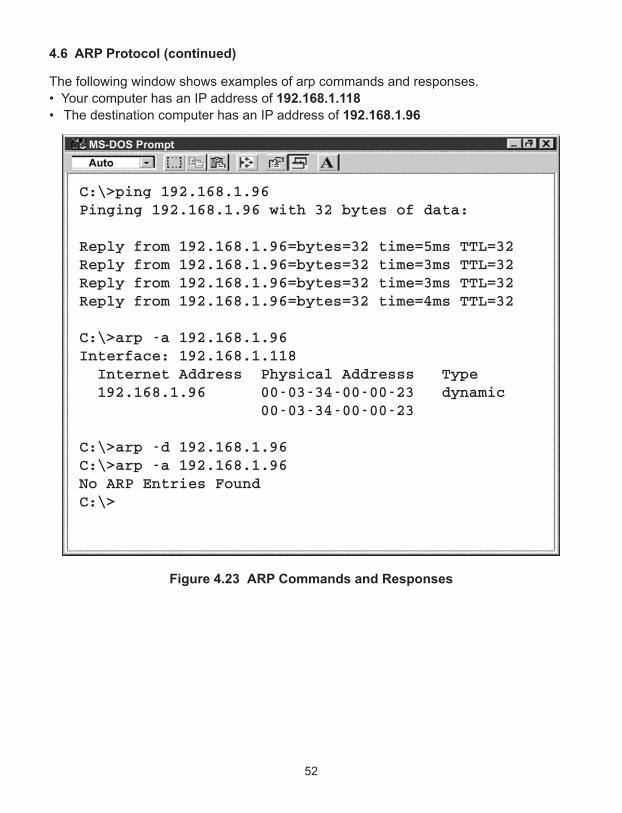
4.6 ARP Protocol (continued)
The following window shows examples of arp commands and responses.
• Your computer has an IP address of 192.168.1.118
• The destination computer has an IP address of 192.168.1.96
Figure 4.23 ARP Commands and Responses
C:\>ping 192.168.1.96 Pinging 192.168.1.96 with 32 bytes of data: Reply from 192.168.1.96=bytes=32 time=5ms TTL=32 Reply from 192.168.1.96=bytes=32 time=3ms TTL=32 Reply from 192.168.1.96=bytes=32 time=3ms TTL=32 Reply from 192.168.1.96=bytes=32 time=4ms TTL=32 C:\>arp -a 192.168.1.96 Interface: 192.168.1.118 Internet Address Physical Addresss Type 192.168.1.96 00-03-34-00-00-23 dynamic 00-03-34-00-00-23 C:\>arp -d 192.168.1.96 C:\>arp -a 192.168.1.96 No ARP Entries Found C:\>
52
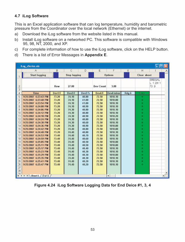
53
4.7 iLog Software
This is an Excel application software that can log temperature, humidity and barometricpressure from the Coordinator over the local network (Ethernet) or the internet.
a) Download the iLog software from the website listed in this manual.
b) Install iLog software on a networked PC. This software is compatible with Windows95, 98, NT, 2000, and XP.
c) For complete information of how to use the iLog software, click on the HELP button.
d) There is a list of Error Messages in Appendix E.
Figure 4.24 iLog Software Logging Data for End Deice #1, 3, 4

54
4.7 iLog Software (continued)
Table 4.1 iLog Excel Applications
The iLog application actually consists of several Excel files, though most supporteddevices can be accessed by the main iLog program. The main program is listed as"iLog", plus a version number, under the Start Menu program links (those links availableby clicking the Start button on the Windows taskbar).
In the following table, the iLog File column shows how many sensors are logged by themain iLog file. If more than 3 sensors are available, then the Alternate column showshow many sensors the device can support. Devices with more than 3 sensors will havetheir own Excel file. For these files, click on the model device found in the Start Menu.
Networked Product iLOG File AlternateiTHX-W, iTHX-2 3 columniTHX-M, iTHX-SD 3 columniTHX-W Dual Probe 1st probe / 3 column 6 columniSE-TC, iSD-TC 3 column 5 columniSE-TH, iSD-TH 3 column 5 columniBTHX-W, iBTHX-D 3 column 4 columniBTX-M, iBTX-SD 2 columniPTX-W 2 columniTCX 3 columniTH Controller 3 columniVI 3 column 4 columniSeries 1 columniDRX/iDRN 1 columnINF-B 1 column
Wireless Devices
The "Auto" column shows number of columns per remote device that are possiblydisplayed.
The Full column shows number of columns allocated per device for the "Full"spreadsheet, which will be able to display all data for all active devices.
Networked Product Auto FullzSeries Receiver and Remotes 1 to 4 column / device 4 column / 32 devicewiSeries with zED Remotes 1 to 2 column / device 2 column / 32 deviceUWTC REC-3 and Remotes 1 or 2 column / device 2 column / 32 devicewiSeries with UWTC Remotes 1 to 2 column / device 2 column / 32 device
The active wireless devices, when shown in the Excel application, will be shown withthe device number and the units returned.

4.8 Mail Notifier Software
For complete information of how to use the Mail Notifier software, click on the Help menuof the main window.
The Mail Notifier software generates email notifications for alarm conditions. Users canbe notified automatically of alarm conditions monitored via internet connectionsthroughout the world. By use of the email forwarding of alarm conditions, alarmconditions can be monitored on a network isolated from the internet and forwarded toconnections on the Internet.
The Mail Notifier utility operates under Windows 98, NT 4.0, 2000, and XP in conjunctionwith existing email that supports the MAPI messaging interface. If MS Outlook has beenloaded, the MAPI support should be available.
4.8.1 InstallationThe Mail Notifier must be loaded on a computer running Microsoft Windows (versionsspecified earlier) using an email program that provides MAPI access. Network accessmust be available between this computer and the zSeries wireless system. Networkaccess must also be available from this computer to the appropriate email server andfrom the email server to the recipient’s email server.
Figure 4.25 Mail Notifier Main Window
iServer Mail Notifier
Status IndicatorsData Email Error
File Monitor Mail View Help
Alerts List
Connected to Email Complete
Dev1 alarm: 74.6Dev2 alarm: 89Dev1 alarm: 74.7Dev1 alarm: 74.7Dev2 alarm: 89Dev1 alarm: 74.7Dev1 alarm: 74.6
55
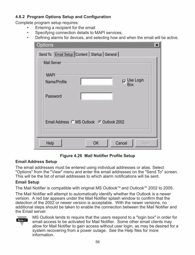
4.8.2 Program Options Setup and Configuration
Complete program setup requires: • Entering a recipient for the email• Specifying connection details to MAPI services.• Defining alarms for devices, and selecting how and when the email will be active.
Figure 4.26 Mail Notifier Profile Setup
Email Address Setup
The email addresses must be entered using individual addresses or alias. Select"Options" from the "View" menu and enter the email addresses on the "Send To" screen.This will be the list of email addresses to which alarm notifications will be sent.
Email Setup
The Mail Notifier is compatible with original MS OutlookTM and OutlookTM 2002 to 2005.
The Mail Notifier will attempt to automatically identify whether the Outlook is a newerversion. A red bar appears under the Mail Notifier splash window to confirm that thedetection of the 2002 or newer version is acceptable. With the newer versions, noadditional steps should be taken to enable the connection between the Mail Notifier andthe Email server.
MS Outlook tends to require that the users respond to a "login box" in order foremail access to be activated for Mail Notifier. Some other email clients mayallow for Mail Notifier to gain access without user login, as may be desired for asystem recovering from a power outage. See the Help files for moreinformation.
Name/Profile
Password
Email Address MS Outlook Outlook 2002
MAPI
Mail Server
Use LoginBox
Email Setup Content Startup GeneralSend To
Help OK Cancel
Options
56
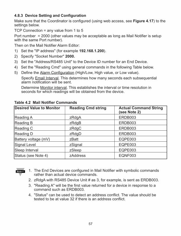
57
4.8.3 Device Setting and Configuration
Make sure that the Coordinator is configured (using web access, see Figure 4.17) to thesettings below.
TCP Connection = any value from 1 to 5
Port number = 2000 (other values may be acceptable as long as Mail Notifier is setupwith the same Port number).
Then on the Mail Notifier Alarm Editor:
1) Set the "IP address" (for example 192.168.1.200).
2) Specify "Socket Number" 2000.
3) Set the "Address/RS485 Unit" to the Device ID number for an End Device.
4) Set the "Reading Cmd" using general commands in the following Table below.
5) Define the Alarm Configuration (High/Low, High value, or Low value).
Specify Email Interval. This determines how many seconds each subsequential alarm notification will be sent.
Determine Monitor interval. This establishes the interval or time resolution in seconds for which readings will be obtained from the device.
Table 4.2 Mail Notifier Commands
Desired Value to Monitor Reading Cmd string Actual Command String (see Note 2)
Reading A zRdgA ERDB003
Reading B zRdgB ERDB003
Reading C zRdgC ERDB003
Reading D zRdgD ERDB003
Battery voltage (mV) zBatt EQPE003
Signal Level zSignal EQPE003
Sleep Interval zSleep EQPE003
Status (see Note 4) zAddress EQNF003
1. The End Devices are configured in Mail Notifier with symbolic commandsrather than actual device commands.
2. zRdgA with RS485 Device Unit # as 3, for example, is sent as ERDB003.
3. "Reading A" will be the first value returned for a device in response to acommand such as ERDB003.
4. "Status" can be used to detect an address conflict. The value should betested to be at value 32 if there is an address conflict.
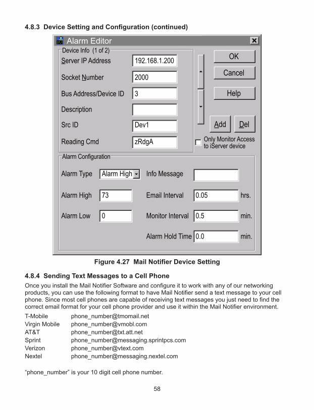
58
4.8.3 Device Setting and Configuration (continued)
Figure 4.27 Mail Notifier Device Setting
4.8.4 Sending Text Messages to a Cell Phone
Once you install the Mail Notifier Software and configure it to work with any of our networkingproducts, you can use the following format to have Mail Notifier send a text message to your cellphone. Since most cell phones are capable of receiving text messages you just need to find thecorrect email format for your cell phone provider and use it within the Mail Notifier environment.
T-Mobile [email protected]
Virgin Mobile [email protected]
AT&T [email protected]
Sprint [email protected]
Verizon [email protected]
Nextel [email protected]
“phone_number” is your 10 digit cell phone number.
Alarm Editor
OK
Cancel
Help
Add Del
Bus Address/Device ID
Socket Number
Description
Src ID
Reading Cmd
Server IP Address
3
2000
Dev1
zRdgA
192.168.1.200Device Info (1 of 2)
Alarm Type
Alarm High
Alarm Low
Alarm High
73
0
Info Message
Email Interval
Monitor Interval
0.05
Alarm Hold Time 0.0
0.5
hrs.
min.
min.
Alarm Configuration
Only Monitor Accessto iServer device
PART 5
eNVIRoNmeNT / oPeRATING coNdITIoNS
End Device/Coordinator are designed to be fixed mounted and operated in a clean anddry environment. Care should be taken to prevent the components of your wirelesssystem from being exposed to moisture, toxic chemicals, extreme cold or hottemperature that are outside the specification listed in this manual.
The following is a list of basic good practice you should apply when operating thisWireless System.
1. Do not operate the wireless device in flammable or explosive environments.
2. Do not use the wireless device in medical, nuclear or any other criticalapplication where failure can cause damage or harm.
3. Always operate the wireless device within the recommended environmental limitsspecified in this manual.
4. Do not operate your wireless device with a battery or AC adapter other thanwhat’s supplied or specified in this manual or on the battery compartment label.
5. Keep each wireless device at least 8 inches (20 cm) from other radiotransmitters, antennas, and people.
6. The FCC approval for this device specifies the specific antenna supplied with thisdevice.
5.1 General Deployment Guidelines
1. Position Coordinator in a central location. When multiple End Devices are inoperation, position your Coordinator in a central space if possible in equaldistance to each End Device.
2. Test your system before permanent mounting. Try to move the devices todifferent location around and mounting angles to determine what installationachieves the best signal strength before permanently mounting the End Device.
3. Move your system components higher off the floor and away from exterior walls.The closer the End Device/Coordinator are, the greater the interference and loseof signal strength will be.
4. Maintain a line-of-sight between antennas and keep Fresnel zone free ofobstruction. See Figure 5.2.
5. Maintain a constant ambient temperature environment. Exposing your systemcomponents to extreme cold or hot temperatures, or sudden changes in ambientconditions will have an effect on the performance of your system.
6. As a general rule in buildings, head height or above is preferred. On the otherhand, End Device stays close to the floor may have their range reduced by 50%to 90%.
59

5.1 General Deployment Guidelines (continued)
7. Where possible, try to ensure an uninterrupted line-of-sight between nodes.Avoid obscuring objects (e.g. metal pillars, posts, sign) near the antenna. A closeobject obscures a wider range of solid angle.
8. It is important to understand that the environment may change over time due tonew equipment or machinery being installed, building construction, etc. If newobstacles exist between your End Device and Coordinator, antenna angle mayneed to be re-adjusted and/or the unit has to be relocated.
9. An IEEE 802.15.4 wireless network will not work under water. Wet condition (e.g.in heavy rainfall) may exhibit some degradation. In most cases, water droplets onor close to the antenna are more serious than the rain itself. Humidity can affectradio performance as well.
10. Reduced performance scenario:
a. A large building may have few obstructions between nodes but large amountof metallic paneling that cause reflections.
b. A small domestic installation may have numerous brick walls between nodesin individual rooms.
c. An office building may have metalized dry-wall partitions together withmezzanine ceilings.
Figure 5.1 Operation in Buildings
Data is sent through radio signal at 2.4 GHz. Radio signals are electromagneticwaves, hence the signal becomes weaker the further it travels.
While radio waves can penetrate some solid materials like a wall, they candiminish more than when a direct line-of-sight between the transmitting andreceiving antenna exist.
Therefore, it is generally a good idea to place Coordinator at the center whileEnd Devices are located about the same distance away from it. If possible,keeping clearance around the line of site will improve performance as well.
Coordinator
CONTROL ROOM
MANUFACTURING
AREA
MANUFACTURING
AREA
End Device
OFFICE OFFICE
STORAGE ROOMEnd Device
End Device
End Device
60
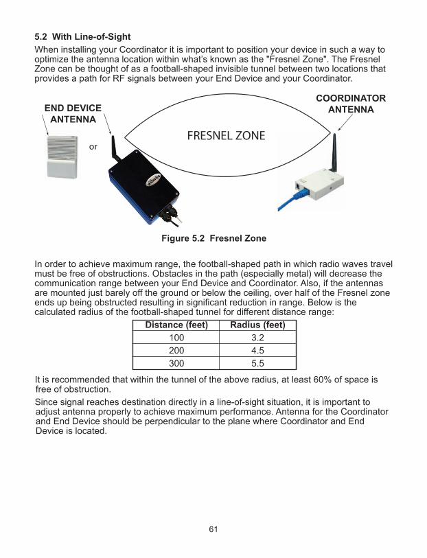
61
5.2 With Line-of-Sight
When installing your Coordinator it is important to position your device in such a way tooptimize the antenna location within what’s known as the "Fresnel Zone". The FresnelZone can be thought of as a football-shaped invisible tunnel between two locations thatprovides a path for RF signals between your End Device and your Coordinator.
Figure 5.2 Fresnel Zone
In order to achieve maximum range, the football-shaped path in which radio waves travelmust be free of obstructions. Obstacles in the path (especially metal) will decrease thecommunication range between your End Device and Coordinator. Also, if the antennasare mounted just barely off the ground or below the ceiling, over half of the Fresnel zoneends up being obstructed resulting in significant reduction in range. Below is thecalculated radius of the football-shaped tunnel for different distance range:
Distance (feet) Radius (feet)
100 3.2
200 4.5
300 5.5
It is recommended that within the tunnel of the above radius, at least 60% of space isfree of obstruction.
Since signal reaches destination directly in a line-of-sight situation, it is important toadjust antenna properly to achieve maximum performance. Antenna for the Coordinatorand End Device should be perpendicular to the plane where Coordinator and EndDevice is located.
or
COORDINATORANTENNAEND DEVICE
ANTENNA

62
5.3 Without Line-of-Sight
When line-of-sight is not possible, signal penetrates and is reflected by different objectsto reach the destination. Therefore, it is important to learn about how these materialswould affect signal propagation. Depending on the thickness, moisture content and angleof incidence, a wall may allow between 1% and 25% of the radio power to pass through.Metal panel or metalized glass window will not allow much radio power to pass through.Signal will be reflected if the panel is a mirror. Some radio power may propagate throughsmall holes in the panel or around metal edges through the process of diffraction.
Material Type Possible Signal Reduction
Wood, Plaster, Sheetrock, FiberglassUncoated Glass w/out Metal 0 to 10%
Brick, Pressboard 5 to 35%
Reinforced Concrete 10 to 90%
Metal Walls, Metal Doors, Elevators, Metal Piping,Metal Stair Cases, Metal Mesh, Metal Screening 90 to 100%
Figure 5.3 Materials in Buildings
In a non-line-of-sight situation at 2.45 GHz, it is possible to move the receive antennaonly 1 to 1 1/2" (3 to 4 cm) and see signal strength varies from 6 dB to -20 dB due tomultiple signal reflection path. Therefore, there should be about 20 dB path loss marginto take signal fading into account.
5.4 Casing and Closure Around the Antenna
1. Metallic structure should be kept at least 0.8" (2 cm), although 2.4" (6 cm) isrecommended away from the antenna.
2. Any casing that encloses the antenna should be plastic. In addition, it is also wiseto avoid plastic case with dark fillers or colorants.

5.5 Fine Adjustment in Performance
1. To avoid interference from WiFi / IEEE 802.11, one could consult the figure below tochoose the best channel through the Configuration webpage. In all, channels 15, 20,25 and 26 are not overlapping with any WiFi / IEEE 802.11 bands in the United Stateswhile channels 15, 16, 21 and 22 can be used in Europe.
Figure 5.4 Channels
2. It is possible that IEEE 802.15.4 devices experience interference from Wi-Fi / IEEE802.11 and Bluetooth devices and certain microwave ovens. Therefore, it is worthlocating nodes as far as possible to minimize effect. Note that international radioregulations which govern radio equipment ensure that cell phones use their allocatedband only. It is highly unlikely that cell phones will interfere with IEEE 802.15.4equipment.
3. In some cases, a short RF cable may be used to connect an antenna to your device.Please note that RF extension cables will always add some loss to the transmittingsignal strength. The longer the cable the more signal will be lost over that cable.Therefore, the length of the cable should be kept as short as possible. Also, note thatuse of any other antenna other then what’s shipped with your device will void FCCand CE regulatory complicance.
4. To achieve satisfactory IEEE 802.15.4 performance in the presence of WLANinterference, a channel center-frequency offset of 7 MHz is recommended.
5. For co-channel operation, a physical separation from the WLAN Access Point (AP) of26.2’ (8 m) is recommended to achieve a Packet Error Rate (PER) of 1%. For aparticularly saturated WLAN link, 29.5’ to 32.8’ (9 to 10 m) may be necessary.
6. To achieve satisfactory IEEE 802.15.4 performance in the presence of Bluetoothinterference, a separation distance of 6.5 ‘ (2 m) is recommended.
US WLAN(IEEE 802.11B)non-overlapping
European WLAN(IEEE 802.11B)non-overlapping
IEEE 802.15.42400 MHz PHY
Channel
1 116
1 137Channel
Channel
2400 MHz 2483.5 MHz2412 2437 2462
2400 MHz 2483.5 MHz
2400 MHz 2483.5 MHz
2412 2442 2472
22 MHz
2 MHz
26252423222120191817161514131211
2405 2410 2415 2420 2425 2430 2435 2440 2445 2450 2455 2460 2465 2470 2475 2480
63

64
PART 6 SPecIFIcATIoNS
SeNSoR SPecS (zed, zedP, zedLcd, zedLcdAA, zedcceLL, zeddceLL, zedH)
ReLATIVe HUmIdITYAccuracy/Range: ±2% for 10 to 90%; zED-BTH, zED-TH, zED-THP; ±3% for 5 to 10% and 90 to 95%; zED-BTHP (-P/-LCD/-AA/-CCELL/-DCELL); ±4% for 0 to 5% and 95 to 100%
zED-THP (-P/-LCD/-AA/-CCELL/-DCELL);
zED-THP2 (-H)
Hysteresis: ±1% RH
Non-linearity: ±3%
Repeatability: ±0.1%
Resolution: 0.1%
TemPeRATUReAccuracy/Range*:
(Internal Sensor) ±0.5ºC for 10º to 55ºC (±0.9ºF for 50º to 131ºF)zED-T ±1ºC for -18º to 10ºC (±1.8ºF for -0.4º to 50ºF)
(External Sensor) ±0.5ºC for 10º to 85ºC (±0.9ºF for 50º to 185ºF)zED-TP1, -TP2; ±1ºC for -40º to 10ºC and 85º to 125ºC zED-TP1/TP2 (-P/-LCD/-AA/-CCELL/-DCELL) (±1.8ºF for -40º to 50ºF and 185 to 257ºF)
Accuracy/Range*:
(Internal Sensor) ±0.5ºC for 0º to 45ºC (±0.9ºF for 32º to 113ºF)zED-BTH, zED-TH ±1ºC for -18º to 0ºC and 45º to 55ºC Refer to chart in Appendix I (±1.8ºF for -0.4º to 32ºF and 113º to 131ºF)
(External Sensor) ±0.5°C for 5 to 45°C (±1°F for 41 to 113°F); zED-THP (-P/-LCD/-AA/-CCELL/-DCELL); Up to ±1.5°C for -40 to 5°C and 45 to 124°CZED-THP2 (-H) (Up to ±2.7°F for -40 to 41°F and 113 to 255°F)
zED-BTHP (-P/-LCD/-AA/-CCELL/-DCELL) ±0.5°C for 5 to 45°C (±1°F for 41 to 113°F)Refer to chart in Appendix I Up to ±1.5°C for -40 to 5°C and 45 to 85°C
(Up to ±2.7°F for -40 to 41°F and 113 to 185°F)
Accuracy/Range*:
(Internal Sensor) ±0.8ºC @ 20ºC (±1.5ºF @ 68ºF)zED-BT ±2ºC for -18º to 55ºC (±3.6ºF for -0.4º to 131ºF)
(External Sensor) ±0.8ºC @ 20ºC (±1.5ºF @ 68ºF)zED-BTP; ±2ºC for -40º to 85ºC (±3.6ºF for -40º to 185ºF) zED-BTP (-P/-LCD/-AA/-CCELL/-DCELL)
*Note: extended temperature ranges are for External Probes only.
Repeatability: ±0.1ºC for -BTH, -BTHP, -TH, -THP, -THP2
Resolution: 0.1ºC
BARomeTRIc PReSSUReAccuracy/Range: ±2 mbar for 10 to 1100 mbar (1 to 110 KPa)
zED-BTH, zED-BT, -BTP;
zED-BTP/BTHP (-P/-LCD/-AA/-CCELL/-DCELL)
Resolution: 0.1 mbar

eXTeRNAL PRoBe SPecIFIcATIoNS (zed, zedP, zedLcd, zedLcdAA, zedcceLL, zeddceLL, zedTHP2xH)
Industrial Probe: SS 316 housing, 137 mm x Ø16 mm (5" x Ø 0.63") for zED-xx-BTP; zED-xx-THP;zED-BTP/BTHP/THP (-P/-LCD/-AA/-CCELL/-DCELL)
Short Quick Disconnect Probe: SS 316 housing, 78 mm x Ø16 mm (3.1" x Ø 0.63") for zED-THP2-xx-H
Stick Probe: ABS tubing, 152.4 mm x Ø6.35 mm (6" x Ø 0.25") for zED-xx-TP1; zED-TP1 (-P/-LCD/-AA/-CCELL/-DCELL)
Lug Mounted Probe: Copper tubing, 53.4 mm x Ø 7.92mm (2.1" x Ø 0.312"); mounting hole Ø 4.72mm (Ø 0.186") for zED-xx-TP2; zED-TP2 (-P/-LCD/-AA/-CCELL/-DCELL)
Cable Dimensions and 3 m (10’) long x Ø 5.72 mm (0.225")Operating Temperature: -40º to 125ºC (-40º to 257ºF) for
zED-xx-THP; zED-xx-TP1; zED-xx-TP2
3 m(10’) long x Ø4.45 mm (0.175") -55º to 105ºC (-67º to 221ºF) for zED-xx-BTP;zED-BTP/BTHP (-P/-LCD/-AA/-CCELL/-DCELL)
3 m (10’) long x Ø2.62 mm (0.103")-80º to 200ºC (-112º to 392ºF) for zED-THP/TP1/TP2 (-P/-LCD/-AA/-CCELL/-DCELL)
THeRmocoUPLe INPUT Temperature Range & Accuracy: Refer to Thermocouple ChartTemperature Stability: 0.08°C/°C Temperature Coefficient: ±25 ppm/°CThermocouple Cold End Tracking: 0.1°C/°CThermocouple Lead Resistance: 100 ohm max.Thermocouple Type (ITS 90): J, K, T, E, R, S, B, C, N, LWarm-Up to Rated Accuracy: 30 minutes
65
TABLE 6.1 THERMOCOUPLE CHARTInput Type Range Accuracy
Iron - Constantan -210 to 760°C / -346 to 1400°F 0.4°C / 0.7°F
-270 to -160°C / -160 to 1372°C 1.0°C / 0.4°CCHROMEGA®- ALOMEGA®
-454 to -256°F / -256 to 2502°F 1.8°F / 0.7°F
-270 to -190°C / -190 to 400°C 1.0°C / 0.4°CCopper - Constantan -454 to -310°F / -310 to 752°F 1.8°F / 0.7°F
-270 to -220°C / -220 to 1000°C 1.0°C / 0.4°CCHROMEGA® - Constantan -454 to -364°F / -364 to 1832°F 1.8°F / 0.7°F
-50 to 40°C / 40 to 1768°C 1.0°C / 0.5°CPt / 13%Rh-Pt -58 to 104°F / 104 to 3214°F 1.8°F / 0.9°F
-50 to 100°C / 100 to 1768°C 1.0°C / 0.5°CPt / 10%Rh-Pt -58 to 212°F / 212 to 3214°F 1.8°F / 0.9°F
100 to 640°C / 640 to 1820°C 1.0°C / 0.5°C30%Rh-Pt / 6%Rh-Pt 212 to 1184°F / 1184 to 3308°F 1.8°F / 0.9°F
5%Re-W / 26%Re-W 0 to 2320°C / 32 to 4208°F 0.4°C / 0.7°F
-250 to -100°C / -100 to 1300°C 1.0°C / 0.4°CNicrosil - Nisil -418 to -148°F / -148 to 2372°F 1.8°F / 0.7°F
J DIN -200 to 900°C / -328 to 1652°F 0.4°C / 0.7°FL

66
INTeRFAce SPecIFIcATIoNS (zcdR)
Ethernet: Standards Compliance IEEE 802.3 10Base-T (RJ45)
Supported Protocols: TCP/IP, ARP, ICMP, DHCP, DNS, HTTP, and Telnet
LED Indicators: Network Activity, Network Link, Diagnostics, Receive and Power
Management: Device configuration and monitoring through embedded WEB server
Embedded WEB Server: Serves WEB pages (Java™ Applets) containing real-time data and live updated charts within definable time intervals
WIReLeSS commUNIcATIoN
Standard: IEEE 802.15.4, DSSS
Frequency: 2.4 GHz (2400 to 2483.5 MHz), 16 channels
Network Topology: Star Topology
Radio Power Output: 100 mW (20 dBm); 10 mW (10 dBm)
Limitations on Equivalent Isotropic Radiated Power (EIRP) levels in the EuropeanCommunity and other countries applies. An improper combination of power level canresult in an EIRP above the allowed amount per regulations. See Appendix H.
Data Rate: Bit rate 250 Kp/s; Symbol rate 62.5 Symbol/s; Chip rate 2000 kchip/s
Modulation: Orthogonal Quaternary Phase Shift Keying (O-QPSK)
Receiver Sensitivity: -100 dBm
Range:
zED Up to 91 m (300 ft) without obstructions or interference
zED-P/-LCD/-H Up to 1000 m (3280 ft) without obstructions or interference-AA/-CCELL/-DCELL
The above ranges assume a line-of-Sight (LOS) between the Meter/Receiver andEnd Device without obstructions or interference at which the diagnostic signalstrength web interface registers approximately 25%.
Antenna Frequency: 2400 to 2500 Mhz
Impedance: 50 ohm
Connector: Reverse Polarity SMA Plug
PoWeR (zcdR)Power Input: 9 to 12 Vdc
Consumption: 2.5 W max.
Safety Qualified ac Power Adapter (included)
Nominal Output: 9 Vdc @ 0.5 A
Input: 100 to 240 Vac, 50/60 Hz
PoWeR (zed)
Alkaline Battery: Two AA 1.5 Vdc, supplied
Lifetime: Estimated 2 years with frequency of 1 reading per 2 minutes

PoWeR (zedP, zedLcd)
Power Input: 5 Vdc
Consumption: 0.8 W max
Safety Qualified ac Power Adapter (included)
Nominal Output: 5 Vdc @ 0.6 A
Input: 100 to 240 Vac, 50/60 Hz
Back-up Lithium Battery: One 3.6 Vdc, supplied; re-order # UWTC-BATT
Lifetime: Estimated 2 years with frequency of 1 reading per 2 minutesEstimated 7 months with frequency of 1 reading per 2 minutes for zED-TC-P, zED-TC-LCD
PoWeR (zedLcdAA, zedLcdAAH, zedAAH)
Alkaline Battery: Two AA 1.5 Vdc, supplied
Lifetime: Estimate of 2.5 years with frequency of 1 reading per 2 minutes
Estimated 8 months with frequency of 1 reading per 2 minutes for zED-TC-LCD-AA
PoWeR (zedcceLL)
Alkaline Battery: Two C-cell 1.5 Vdc, suppliedLifetime: Estimate of 7 years with frequency of 1 reading per 2 minutes
Estimated 2.3 years with frequency of 1 reading per 2 minutes for zED-TC-CCELL
Table 6.2
Alkaline Battery Estimated Lifetime Frequency zED-TC/VI-LCD-AA zED-TC/VI-CCELL zED-TC/VI-DCELL continuous sraey 5.4 skeew 2 syad 5
10 sec sraey 5.3 sraey 4.1 shtnom 530 sec sraey 8.4 sraey 2 shtnom 2.760 sec sraey 6.5 sraey 2.2 shtnom 9.7120 sec 8 months 2.3 years 5.6 years 300 sec sraey 8.5 sraey 4.2 shtnom 6.8
Frequency zED-TP/THP/BTP/BTHP-LCD-AA &
zED-TP/THP/BTP/BTHP-CCELL
zED-TP/THP/BTP/BTHP-DCELL
10 sec sraey 4 sraey 7.1 shtnom 3.530 sec xam sraey 7 sraey 3.4 sraey 1.160 sec 1.7 years 7 years max 7 years max 120 sec 2.5 years 7 years max 7 years max 300 sec 3.3 years 7 years max 7 years max
zED-THP2-LCD-AA-H/-AA-H
67

68
eNVIRoNmeNT
Operating Temperatures:
zED, zED-CCELL, -CCELL-H, -DCELL: -18º to 55ºC (-0.4º to 131ºF) 90% RH, non-condensing
zED-P: -20º to 70ºC (-4º to 158ºF) 90% RH, non-condensing
zED-LCD: -10º to 60ºC (14º to 140ºF) 90% RH, non-condensing
zED-LCD-AA, zED-LCD-AA-H: -10º to 55ºC (14º to 131ºF) 90% RH, non-condensing
zCDR: 0º to 70ºC (32º to 158ºF) 90% RH, non-condensing
AC Power Adapter: 0º to 40ºC (32º to 104ºF)
Storage Temperatures:
zED, zED-P/-CCELL/DCELL, zCDR: -40º to 125ºC (-40º to 257ºF), with exception of batteries
zED-LCD, Antenna, AC Adapter: -20º to 70ºC (-4º to 158ºF)
SAFeTY & ReGULAToRY comPLIANce
Safety: EN60950-1:2006 (IEC 60950-1:2005)Safety Requirement under article 3.1.a of the R&TTE
EMC: EN 301 489-1, V1.6.1:2005-09Electromagnetic compatibility article 3.1.b of the R&TTE
EN 301 489-17, V1.2.1:2002-08Electromagnetic compatibility article 3.1.b of the R&TTE
EN 55022:2006 + A1:2007, Class B, (CISPR 22 +A1:2005)
Radio: EN 300 328 V1.7.1:2006-10Spectrum article 3(2) of the R&TTE
FCC: Part 15C, Class DTS Intentional radiator tested for 15.205, 15.209,15.247(d), 15.215(c), 15.247(a)(2), 15.247(b), 15.247(e) (SeeAppendix H).
CE: The product herewith complies with the essential requirements andother relevant provisions of the R&TTE Directive 1999/5/EC, theEMC Directive 2004/108/EC, and the Low Voltage Directive2006/95/EC, and carries the CE-marking accordingly.The following CE Mark is affixed to this equipment.
See Appendix H. The CE declaration is available at the websitelisted on the cover page of this manual.
PAckAGING See Section 2.0
GeNeRAL
Software: The software packages available for the zSeries wireless system are iConnect
(configuration software for the Ethernet interface), iLog (Excel-based software for automaticdata logging), and Mail Notifier (email alarm notification software).
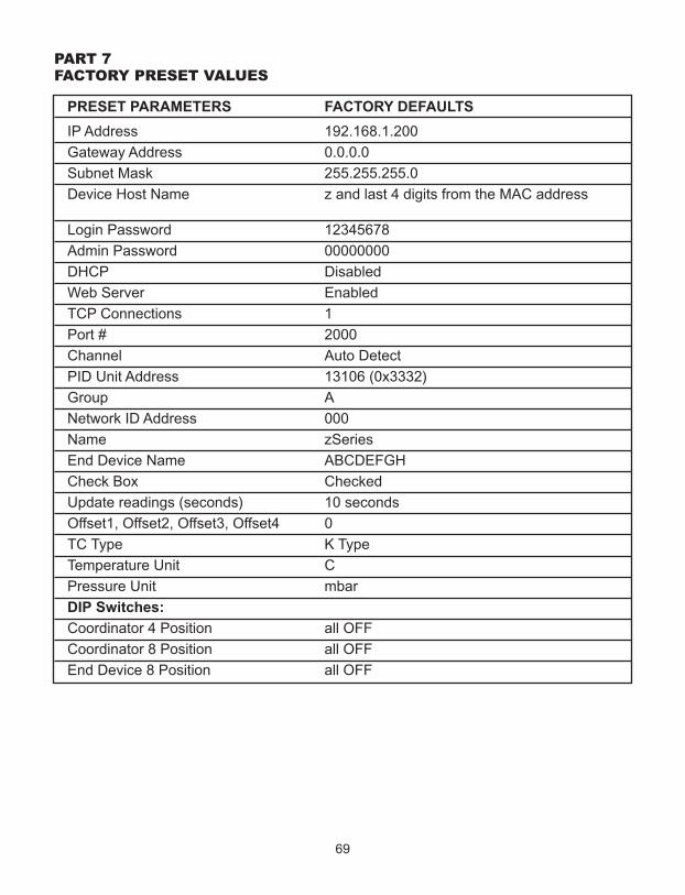
69
PART 7FAcToRY PReSeT VALUeS
PRESET PARAMETERS FACTORY DEFAULTS
IP Address 192.168.1.200
Gateway Address 0.0.0.0
Subnet Mask 255.255.255.0
Device Host Name z and last 4 digits from the MAC address
Login Password 12345678
Admin Password 00000000
DHCP Disabled
Web Server Enabled
TCP Connections 1
Port # 2000
Channel Auto Detect
PID Unit Address 13106 (0x3332)
Group A
Network ID Address 000
Name zSeries
End Device Name ABCDEFGH
Check Box Checked
Update readings (seconds) 10 seconds
Offset1, Offset2, Offset3, Offset4 0
TC Type K Type
Temperature Unit C
Pressure Unit mbar
DIP Switches:
Coordinator 4 Position all OFF
Coordinator 8 Position all OFF
End Device 8 Position all OFF
APPeNdIX A GLoSSARY
User of this manual should be familiar with following definitions:
ARP (Address Resolution Protocol) is a protocol for mapping an Internet Protocol address (IP address) to a physical machine address that is recognized in the localnetwork. For example, the IP address in use today is an address that is 32-bits long. In an Ethernet local area network, however, addresses for attached devices are 48-bitslong. (The physical machine address is also known as a Media Access Control or MAC address.) A table, usually called the ARP cache, is used to maintain a correlationbetween each MAC address and its corresponding IP address. ARP provides theprotocol rules for making this correlation and providing address conversion in bothdirections.
Ethernet is a network protocol defined by the IEEE 802.3 standard. Ethernet-based networks use MAC Address rather then IP Address to exchange data betweencomputers. By using ARP and adding TCP/IP support, Ethernet devices may beconnected as part of the Internet. An Ethernet LAN typically uses coaxial cable or specialgrades of twisted pair wires. The most commonly installed Ethernet systems are called10BASE-T and provide transmission speeds up to 10 Mbps. Devices are connected tothe cable and compete for access using a Carrier Sense Multiple Access with CollisionDetection (CSMA/CD) protocol.
IP (Internet Protocol) is the method or protocol by which data is sent from one computerto another on the Internet.
IP address (Internet Protocol address) is a 32-bit number that identifies each senderor receiver of information that is sent in packets across the Internet.
IP Netmask is a 32-bit pattern of bits used to determine which part of the IP address isthe network portion and which part is the host portion.
MAC (Media Access Control) Address is your computer's unique hardware number.When you're connected to the Internet from your computer, a correspondence tablerelates your IP address to your computer's physical (MAC) address on the LAN.
Ping is a utility that tests the network connectivity. It is used to determine if the host iscapable of exchanging information with another host.
Port number/Socket number is a way to identify a specific process to which an Internetor other network message is to be forwarded when it arrives at a server. It is apredefined address that serves as a route from the application to the Transport layer orfrom the Transport layer to the application of the TCP/IP system.
Sockets are a method for communication between a client program and a serverprogram in a network and defined as "the endpoint in a connection". Informationtransferred across the Internet primarily occurs between sockets.
TCP/IP (Transmission Control Protocol/Internet Protocol) is the basic communicationlanguage or protocol of the Internet. When you are set up with direct access to theInternet, your computer is provided with a copy of the TCP/IP program just as everyother computer that you may send messages to or get information from also has a copyof TCP/IP. TCP/IP often is used as a general term to indicate generic access to theInternet.
70
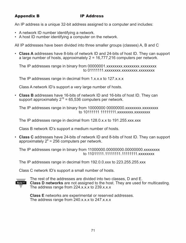
Appendix B IP Address
An IP address is a unique 32-bit address assigned to a computer and includes:
• A network ID number identifying a network.• A host ID number identifying a computer on the network.
All IP addresses have been divided into three smaller groups (classes) A, B and C
• Class A addresses have 8-bits of network ID and 24-bits of host ID. They can support a large number of hosts, approximately 2 = 16,777,216 computers per network.
The IP addresses range in binary from 00000001.xxxxxxxx.xxxxxxxx.xxxxxxxxto 01111111.xxxxxxxx.xxxxxxxx.xxxxxxxx
The IP addresses range in decimal from 1.x.x.x to 127.x.x.x
Class A network ID’s support a very large number of hosts.
• Class B addresses have 16-bits of network ID and 16-bits of host ID. They can support approximately 216 = 65,536 computers per network.
The IP addresses range in binary from 10000000 00000000.xxxxxxxx.xxxxxxxxto 10111111 11111111.xxxxxxxx.xxxxxxxx
The IP addresses range in decimal from 128.0.x.x to 191.255.xxx.xxx
Class B network ID’s support a medium number of hosts.
• Class C addresses have 24-bits of network ID and 8-bits of host ID. They can support approximately 28 = 256 computers per network.
The IP addresses range in binary from 11000000.00000000.00000000.xxxxxxxx to 11011111.11111111.11111111.xxxxxxxx
The IP addresses range in decimal from 192.0.0.xxx to 223.255.255.xxx
Class C network ID’s support a small number of hosts.
The rest of the addresses are divided into two classes, D and E.Class D networks are not assigned to the host. They are used for multicasting. The address range from 224.x.x.x to 239.x.x.x
Class E networks are experimental or reserved addresses.The address range from 240.x.x.x to 247.x.x.x
71

Appendix c IP Netmask
IP Netmask or Subnet Mask is a 32-bit pattern of ones and zeros used to determinenetwork portion of an IP address from the host portion of the IP address. Subnet mask isa network ID that is created by borrowing bits from host portion of IP address and usingthem as part of a network ID. The table below shows a default subnet mask for addressClasses A, B, and C. Each bit that is set to "1" in the subnet mask corresponds to the bitin the IP address that is to be used as the network ID. Each bit that is set to "0" in thesubnet mask corresponds to a bit in the IP address that is to be used as the host ID.
Address Class Mask Binary Value Mask Decimal Valueor Dotted Notation
Class A 255.0.0.0Class B 255.255.0.0Class C 255.255.255.0
If your network requires more network ID’s, you can extend the default subnet mask toinclude additional bits from the host ID. This allows for additional network ID’s within thenetwork. The table below shows some examples of subnet masks and bits moved fromthe hosts ID to create a new subnet.
Mask Dotted Notation Mask Binary Mask Bits
Class A255.0.0.0 (Default) 0255.192.0.0 2255.224.0.0 3255.240.0.0 4255.248.0.0 5255.252.0.0 6255.254.0.0 7255.255.0.0 8255.255.128.0 9255.255.192.0.0 10……………......... .255.255.255.252 22
Class B255.255.0.0 (Default) 0255.255.192.0 2……………......... .255.255.255.252 14
Class C255.255.255.0 (Default) 0255.255.255.192 2…………………. .255.255.255.254 6
To determine the number of valid hosts ID’s remaining after subnetting, use the followingequation: 2n – 2, where n is the number of octet digits left after the subnet mask.
72
111111111111111111111111
000000001111111111111111
000000000000000011111111
000000000000000000000000
11111111111111111111111111111111111111111111111111111111111111111111111111111111. . . . . . . .11111111
00000000110000001110000011110000111110001111110011111110111111111111111111111111. . . . . . . .11111111
00000000000000000000000000000000000000000000000000000000000000001000000011000000. . . . . . . .11111111
00000000000000000000000000000000000000000000000000000000000000000000000000000000. . . . . . . .11111100
1111111111111111. . . . . . . .11111111
1111111111111111. . . . . . . .11111111
0000000011000000. . . . . . . .11111111
0000000000000000. . . . . . . .11111100
1111111111111111. . . . . . . .11111111
1111111111111111. . . . . . . .11111111
1111111111111111. . . . . . . .11111111
0000000011000000. . . . . . . .11111100

Appendix d AScII chart
ASCII Dec Hex Binary ASCII Dec Hex BinaryChar No Parity Char No parityNUL 00 00 00000000 @ 64 40 01000000SOH 01 01 00000001 A 65 41 01000000STX 02 02 00000010 B 66 42 01000010ETX 03 03 00000011 C 67 43 01000011EOT 04 04 00000100 D 68 44 01000100ENQ 05 05 00000101 E 69 45 01000101ACK 06 06 00000110 F 70 46 01000110BEL 07 07 00000111 G 71 47 01000111BS 08 08 00001000 H 72 48 01001000HT 09 09 00001001 I 73 49 01001001LF 10 0A 00001010 J 74 4A 01001010VT 11 0B 00001011 K 75 4B 01001011FF 12 0C 00001100 L 76 4C 01001100CR 13 0D 00001101 M 77 4D 01001101SO 14 0E 00001110 N 78 4E 01001110SI 15 0F 00001111 O 79 4F 01001111
DLE 16 10 00010000 P 80 50 01010000DC1 17 11 00010001 Q 81 51 01010001DC2 18 12 00010010 R 82 52 01010010DC3 19 13 00010011 S 83 53 01010011DC4 20 14 00010100 T 84 54 01010100NAK 21 15 00010101 U 85 55 01010101SYN 22 16 00010110 V 86 56 01010110ETB 23 17 00010111 W 87 57 01010111CAN 24 18 00011000 X 88 58 01011000EM 25 19 00011001 Y 89 59 01011001
SUB 26 1A 00011010 Z 90 5A 01011010ESC 27 1B 00011011 [ 91 5B 01011011FS 28 1C 00011100 \ 92 5C 01011100GS 29 1D 00011101 ] 93 5D 01011101RS 30 1E 00011110 ^ 94 5E 01011110US 31 1F 00011111 _ 95 5F 01011111SP 32 20 00100000 ` 96 60 01100000! 33 21 00100001 a 97 61 01100001" 34 22 00100010 b 98 62 01100010# 35 23 00100011 c 99 63 01100011$ 36 24 00100100 d 100 64 01100100% 37 25 00100101 e 101 65 01100101& 38 26 00100110 f 102 66 01100110‘ 39 27 00100111 g 103 67 01100111( 40 28 00101000 h 104 68 01101000) 41 29 00101001 I 105 69 01101001* 42 2A 00101010 j 106 6A 01101010+ 43 2B 00101011 k 107 6B 01101011, 44 2C 00101100 l 108 6C 01101100- 45 2D 00101101 m 109 6D 01101101. 46 2E 00101110 n 110 6E 01101110
73

Appendix d AScII chart continuation
/ 47 2F 00101111 o 111 6F 011011110 48 30 00110000 p 112 70 011100001 49 31 00110001 q 113 71 011100012 50 32 00110010 r 114 72 011100103 51 33 00110011 s 115 73 011100114 52 34 00110100 t 116 74 011101005 53 35 00110101 u 117 75 011101016 54 36 00110110 v 118 76 011101107 55 37 00110111 w 119 77 011101118 56 38 00111000 x 120 78 011110009 57 39 00111001 y 121 79 01111001: 58 3A 00111010 z 122 7A 01111010; 59 3B 00111011 123 7B 01111011< 60 3C 00111100 | 124 7C 01111100= 61 3D 00111101 125 7D 01111101> 62 3E 00111110 ~ 126 7E 01111110? 63 3F 00111111 DEL 127 7F 01111111
AScII control codes
ASCII Dec Hex Ctrl Key Definition ASCII Dec Hex Ctrl Key DefinitionChar Equiv. Char Equiv.NUL 00 00 Crtl @ Null Character DC1 17 11 Crtl Q Data Control 1
- XONSOH 01 01 Crtl A Start of DC2 18 12 Crtl R Data Control 2
HeaderSTX 02 02 Crtl B Start of Text DC3 19 13 Crtl S Data Control 3
- XOFFETX 03 03 Crtl C End of Text DC4 20 14 Crtl T Data Control 4EOT 04 04 Crtl D End of NAK 21 15 Crtl U Negative
Transmission AcknowledgeENQ 05 05 Crtl E Inquiry SYN 22 16 Crtl V Synchronous
IdleACK 06 06 Crtl F Acknowledge ETB 23 17 Crtl W End of Trans
BlockBEL 07 07 Crtl G Bell CAN 24 18 Crtl X CancelBS 08 08 Crtl H Back Space EM 25 19 Crtl Y End of MediumHT 09 09 Crtl I Horizontal SUB 26 1A Crtl Z Substitute
TabulationLF 10 0A Crtl J Line Feed ESC 27 1B Crtl [ EscapeVT 11 0B Crtl K Vertical FS 28 1C Crtl \ File Separator
TabulationFF 12 0C Crtl L Form Feed GS 29 1D Crtl ] Group
SeparatorCR 13 0D Crtl M Carriage RS 30 1E Crtl | Record
Return SeparatorSO 14 0E Crtl N Shift Out US 31 1F Crtl _ Unit SeparatorSI 15 0F Crtl O Shift In SP 32 20 Space
DLE 16 10 Crtl P Data LinkEscape
74

Appendix e iLog error messages
Error # Description Note
-8003 User stopped logging readings.
-10005 Failed to find the Coordinator. Ethernet cable is disconnected, Coordinator is powered off, connections across the firewall require longer "connection to sockettime out" setting.
-10006 Windows socket was closed.
-10007 Windows socket error. Wrong IP or wrong Port number was used.
-10008 The Coordinator failed to respond to a request. Wrong IP or wrong Port number was used.
-10011 Response came empty. No data was sent.
-10012 Device responded with Possibly the iLog is configured for"Serial Time Out" string. wrong product model.
-10014 Terminal Server Mode when the Port is 1000. Try Port 2000 in iLog configuration.
-15100 Error on obtaining the temperature reading. Possibly the iLog is configured for wrong product model.
-15105 Error on obtaining the humidity reading. Possibly the iLog is configured for wrong product model.
-15110 Error on obtaining the dew point reading. Possibly the iLog is configured for wrong product model.
75

Appendix F AScII / TeLNeT commANdS TABLe
Command Device / Group ID Description (see notes below if *) ExampleERCR Device ID: 000 – 031 Get continuous readings from an Get reading for sensor 7,
End Device (only TC & VI) ERCR007
ERDB Device ID: 000 – 031 Get sensor readings of an End Device Get reading for sensor 15,ERDB015
ERDR Device ID: 000 – 031 Get individual reading or parameter Get the first temp. readingReading/parameter: as *4 for sensor 1, ERDR001c
ERDG Group ID: 00A 00D, ALL Get sensor readings of a group / Get readings for all *5 groups of sensors group B, ERDG00B
EQNF Device ID: 000 – 031 Get name, *3 status and firmware Get name for sensor 15,version of an End Device EQNF015
EQNG Group ID00A 00D, ALL Get name, *3 status and firmware Get name for all sensors,version of a group/all groups of sensors EQNGALL
EQPE Device ID: 000 – 031 Get sleep period, battery voltage, signal Get sleep period for strength, success, network address and sensor 15, EQPE015parent address of an End Device
EQPG Group ID: 00A 00D Get sleep period, battery voltage, signal Get sleep period of strength, success, network address and group B, EQPG00Bparent address of a group / all groupsof sensors
ESPD Device ID: 000031, ALL Set the sleep period for an End Device / Set sensor 15’s sleep all sensors *1 period to 30 seconds,
ESPD015 30
ESNM Device ID: 000 – 031 Set the name of an End Device *2 Set the name of sensor 15,ESNM015 z15
ERST Device ID: 000 – 031, ALL Reset an End Device / all sensors Reset all sensors, ERSTALL
ESTR Device ID: 000 – 031, ALL Request End Device(s) to go into Put all sensors intoidentify mode identify mode, ESTRALL
ESTP Device ID: 000 – 031, ALL Request End Device(s) to resume Resume all sensor to normal operation normal operation, ESTPALL
CRST Reset wireless network Reset network, CRST
CSTS Get personal network ID and channel Get wireless network information information, CSTS
FACTORY Sets the Coordinators Ethernet FACTORY xxxxxxxxAdminPassword configurations to Factory Defaults xxxxxxxx is the Admin
Password
*1 Argument: 1 – 32767 (1 seconds to about 9 hours)
*2 Argument: xxxxxxxx (8 characters)
*3 and *4 See the following page
*5 Refer to Section 4.5.1 HTTPget using Port 2000
76
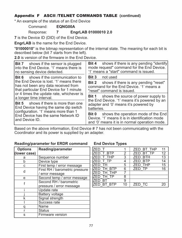
Appendix F AScII /TeLNeT commANdS TABLe (continued)
* An example of the status of an End Device
Command: EQNG00A
Response: 7 EngrLAB 01000010 2.0
7 is the Device ID (DID) of the End Device.
EngrLAB is the name for the End Device.
"01000010" is the bitmap representation of the internal state. The meaning for each bit isdescribed below (bit 7 starts from the left).
2.0 is version of the firmware in the End Device.
Based on the above information, End Device # 7 has not been communicating with theCoordinator and its power is supplied by an adapter.
Reading/parameter for ERDR command End Device Types
Options Reading/parameter(lower case)
a Sequence numberb Device typec First temp / error message
dFirst RH / barometric pressure / error message
e Second temp / error message
fSecond RH / barometric pressure / error message
i Update ratej Battery voltagek Signal strengthl Success rateq Namer Statuss Firmware version
77
Bit 7 shows if the sensor is pluggedinto the End Device. ‘1’ means there isno sensing device detected.
Bit 6 shows if the communication tothe End Device is lost. ‘1’ means therehas not been any data received fromthat particular End Device for 1 minuteor 4 times the update rate, whichever isa longer time interval.
Bit 5 shows if there is more than oneEnd Device having the same dip switchconfiguration. ‘1’ means more than 1End Device has the same Network IDand Device ID.
Bit 4 shows if there is any pending "identifymode request" command for the End Device.‘1’ means a "start" command is issued.
Bit 3 not used
Bit 2 shows if there is any pending "reset"command for the End Device. ‘1’ means a"reset" command is issued.
Bit 1 shows the source of power supply tothe End Device. ‘1’ means it’s powered by anadapter and ‘0’ means it’s powered bybatteries.
Bit 0 shows the operation mode of the EndDevice. ‘1’ means it is in identification modeand ‘0’ means it is in normal operation mode.
ZED_T 1 ZED_BT_THP 11ZED_T_BTP 2 ZED_BT_TP 12ZED_T_THP 3 ZED_BTH 13ZED_T_TP 4 ZED_BTP 14ZED_TH 5 ZED_THP 15ZED_TH_BTP 6 ZED_TP 16ZED_TH_THP 7ZED_TH_TP 8ZED_BT 9ZED_BT_BTP 10 ZED_TC 20
78
Appendix G Frequently Asked Questions (FAQ)
Q: Java applet is not loaded?
A: Check Java Setting (icon in Control Panel). Make sure cache is disabled and yourweb browser is enabled for Java.
Q: I do not see any readings even if the applet is loaded, what could be wrong?
A: 1) Make sure the Coordinator and the End Device have the same Network ID (NID).
2) Check if the battery is still good. You should be able to see the blue LED when youpower the End Device on.
3) If the End Device keeps blinking every second after it is powered on, that means itcannot find the Coordinator. Try to adjust the antenna and relocate the End Deviceaccording to Section 5.1.
Q: What are the error messages that appear on the "Reading", "Chart", and "Diagnostic"pages?
Open
A: It means that the End Device cannot detect any of its sensors.
Check the connections for the internal sensor and the external probe if any.
ID
A: It means that there are more than one End Device sharing the same Device ID (DIPswitches #1-5).
Remember, each sensor should have a unique Device ID in the same wireless network.Turning the device into Identify Mode may help searching for the physical location ofsuch End Devices. Once the problem is resolved, click on the "Reset Sensor" buttonlocated on the Sensors Parameters page to remove the "ID" error code.
Lost
A: It means that the End Device found the Coordinator when it was powered on, but itcannot communicate with it currently.
Make sure the Coordinator and the End Device have the same Network ID (NID). Also,make sure the Coordinator is powered on, the IEEE802.15.4 communication channel isunchanged, DIP switch #1 (of the 8-DIP switch row) on the Coordinator was ON duringthe last Coordinator’s power reset, and there is no obstructive objects blocking thecommunications path (see Section 5 for more details). If the obstructive object is onlytemporary, you will get the sensor readings once the path is open.
Q: Nothing happens when I click on the Data Logging button, what could be wrong?
A: The Java policy file is not setup properly. Make sure you get a Java policy file andcopy it to a folder in the host computer. Then input the java runtime argument in JavaSetup (Control Panel) with the appropriate path to the policy file. Close all web browserand re-open the applet again. See Java Setup Section.
Appendix G Frequently Asked Questions (FAQ) (continued)
Q: The Chart trend line for all the variables are broken, what could be wrong?
A: It indicates that a TCP connection to the Coordinator was timed-out and no data wasobtained. Make sure the Coordinator is still on in the network and powered up. If thereare too many broken lines, it may indicate that the network load is too heavy.
Q: The trend line for one of my sensors inside one End Device is broken, what could bewrong?
A: It indicates that TCP connection to the Coordinator is good but the Coordinator didnot have any readings from the corresponding End Device. Make sure End Device is stillblinking according to the update rate. It could be caused by a reset/power cycling of theCoordinator as well.
Q: Nothing happens when I click on the Save Current Graph button, what could bewrong?
A: The Java policy file is not setup properly. Make sure you get a Java policy file andcopy it to a folder in the host computer. Then input the java runtime argument in JavaSetup (Control Panel) with the appropriate path to the policy file. Close all web browserand re-open the applet again. See Java Setup Section.
Q: Nothing is shown inside the Diagnostic page/applet, what could be wrong?
A: The first thing you want to try is to click your mouse right inside the box. Thenminimize and restore the web browser. Try to move the scrollbar as well. If nothing worksafter about a minute, check the TCP connection to the Coordinator.
Q: The End Device repeatedly makes 4 blinks every 2 seconds and then goes off for 3minutes, what does this mean?
A: It is equivalent to getting a "Lost" message in the Java applets. It means that the EndDevice found the Coordinator when it was powered on, but it cannot communicate with itcurrently. Make sure the Coordinator and the End Device have the same Network ID(NID). Also, make sure the Coordinator is powered on, the IEEE802.15.4 communicationchannel is unchanged, the first DIP switch (of the 8-DIP switch row) on the Coordinatorwas on during the last Coordinator’s power reset, and there is no obstructive objectsblocking the communications path (see Section 5 for more details). If the obstructiveobject is only temporary, you will get the sensor readings once the path is open.
Q: While the End Device is up and running I notice a sequence of blinking patterns thatseem to repeat themselves, what could be wrong?
A: It means that the End Device needs several retransmissions before getting anacknowledgement packet back from the Coordinator. This indicates a reducedperformance since more retransmissions required. Retransmissions consume power andcause shorter battery lifetime. Adjust the antenna and relocate the End Device for bettercommunications. See Section 5 for more details.
79

80
Appendix H Warnings and Regulatory Information
In order to comply with FCC radio frequencies (RF) exposure limits, dipole antennasshould be located at a minimum 7.9" (200mm) or more from the body of all persons.
This device complies with part 15 rules. Operation is subject to the following two conditions:1) this device may not cause harmful interference, and
2) this device must accept any interference received, including interference that may causeundesired operation.
This equipment has been tested and found to comply with the limits of a Class B digitaldevice, pursuant to Part 15 of the FCC Rules. These limits are designed to providereasonable protection against harmful interference when the equipment is operated in aresidential environment. This equipment generates, uses, and radiates radio frequencyenergy, and if not installed and used in accordance with the instructions, may cause harmfulinterference. However, there is no guarantee that interference will not occur. If this equipmentdoes cause interference to radio or television reception, which can be determined by turningthe equipment off and on, the user is encouraged to correct the interference by one of thefollowing measures:
• Reorient or relocate the receiving antenna.• Increase separation between the equipment and receiver.• Connect the equipment to an outlet on a circuit different from which the receiver is
connected.• Consult dealer or an experienced radio/TV technician.
The following alert sign indicates that there are restrictions on usage of theequipment in regards to power limitations on Equivalent Isotropic Radiated Power(EIRP) levels in the European Community.
The following are user restrictions:
• Wideband Data Transmission Systems on the band 2400 – 2483.5 MHz in Europe islimited to a Maximum of 10 mW (10dBm) for Direct Sequence Spread Spectrum (DSSS).See Annex 3 of ERC/REC 70-03, decision ERC/DEC/ (01)07.
• Combinations of power levels and antennas resulting in a radiated power level above 10 mW - EIRP for Direct Sequence Spectrum (DSSS) devices are considered as notcompliant, and are not allowed for use within the European Community and othercountries that have adopted the European R&TTE directive 1995/5/EC or the CEPTrecommendation ERC/REC 70-03 or both.
• The users in Europe are instructed to change the default 20 dBm level to 10 dBm via theWeb Interface of the Coordinator. The End Devices will follow the power level set on theCoordinator upon power-up; failure to change the default U.S.A. power level setting willviolate the regulations requirements for Europe
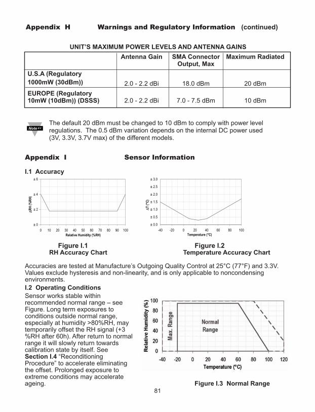
Appendix H Warnings and Regulatory Information (continued)
UNIT’S MAXIMUM POWER LEVELS AND ANTENNA GAINS
Antenna Gain SMA Connector Maximum RadiatedOutput, Max
U.S.A (Regulatory
1000mW (30dBm)) 2.0 - 2.2 dBi 18.0 dBm 20 dBm
EUROPE (Regulatory 10mW (10dBm)) (DSSS) 2.0 - 2.2 dBi 7.0 - 7.5 dBm 10 dBm
The default 20 dBm must be changed to 10 dBm to comply with power levelregulations. The 0.5 dBm variation depends on the internal DC power used (3V, 3.3V, 3.7V max) of the different models.
Appendix I Sensor Information
I.1 Accuracy
Figure I.1 Figure I.2RH Accuracy Chart Temperature Accuracy Chart
Accuracies are tested at Manufacture’s Outgoing Quality Control at 25°C (77°F) and 3.3V.Values exclude hysteresis and non-linearity, and is only applicable to noncondensingenvironments.
I.2 Operating Conditions
Sensor works stable withinrecommended normal range – seeFigure. Long term exposures toconditions outside normal range,especially at humidity >80%RH, maytemporarily offset the RH signal (+3%RH after 60h). After return to normalrange it will slowly return towardscalibration state by itself. SeeSection I.4 “ReconditioningProcedure” to accelerate eliminatingthe offset. Prolonged exposure toextreme conditions may accelerateageing. Figure I.3 Normal Range
81

Appendix I Sensor Information (continued)I.3 Storage Conditions and Handling Instructions
It is of great importance to understand that a humidity sensor is not a normal electroniccomponent and needs to be handled with care.
Chemical vapors at high concentration in combination with long exposure times may offsetthe sensor reading. For these reasons it is recommended to store the sensors in originalpackaging including the sealed ESD bag at following conditions: Temperature shall be in therange of 10°C – 50°C (0 – 80°C for limited time) and humidity at 20 – 60%RH (sensors thatare not stored in ESD bags). For sensors that have been removed from the originalpackaging we recommend to store them in ESD bags made of PE-HD8.
In manufacturing and transport the sensors shall be prevented of high concentration ofchemical solvents and long exposure times. Out-gassing of glues, adhesive tapes andstickers or out-gassing packaging material such as bubble foils, foams, etc. shall be avoided.Manufacturing area shall be well ventilated.
I.4 Reconditioning Procedure
As stated above extreme conditions or exposure to solvent vapors may offset the sensor. Thefollowing reconditioning procedure may bring the sensor back to calibration state:
Baking: 100 – 105°C at < 5%RH for 10h
Re-Hydration: 20 – 30°C at ~ 75%RH for 12h.
(75%RH can conveniently be generated with saturated NaCl solution. 100 – 105°Ccorrespond to 212 – 221°F, 20 – 30°C correspond to 68 – 86°F)
I.5 Temperature Effects
Relative humidity reading strongly depends on temperature. Therefore, it is essential to keephumidity sensors at the same temperature as the air of which the relative humidity is to bemeasured. In case of testing or qualification the reference sensor and test sensor must showequal temperature to allow for comparing humidity readings.
The packaging of sensor is designed for minimal heat transfer from the pins to the sensor.Still, if the sensor shares a PCB with electronic components that produce heat it should bemounted in a way that prevents heat transfer or keeps it as low as possible. Furthermore,there are self-heating effects in case the measurement frequency is too high.
I.6 Light
The sensor is not light sensitive. Prolonged direct exposure to sunshine or strong UVradiation may age the housing.
I.7 Materials Used for Sealing / Mounting
Many materials absorb humidity and will act as a buffer increasing response times andhysteresis. Materials in the vicinity of the sensor must therefore be carefully chosen.Recommended materials are: Any metals, LCP, POM (Delrin), PTFE (Teflon), PE, PEEK, PP,PB, PPS, PSU, PVDF, PVF. For sealing and gluing (use sparingly): Use high filled epoxy forelectronic packaging (e.g. glob top, underfill), and Silicone.
Out-gassing of these materials may also contaminate the sensor (see Section I.3). Thereforetry to add the sensor as a last manufacturing step to the assembly, store the assembly wellventilated after manufacturing or bake at 50°C for 24h to outgas contaminants beforepacking.
82

NoTeS
______________________________________________________________________________
______________________________________________________________________________
______________________________________________________________________________
______________________________________________________________________________
______________________________________________________________________________
______________________________________________________________________________
______________________________________________________________________________
______________________________________________________________________________
______________________________________________________________________________
______________________________________________________________________________
______________________________________________________________________________
______________________________________________________________________________
______________________________________________________________________________
______________________________________________________________________________
______________________________________________________________________________
______________________________________________________________________________
______________________________________________________________________________
______________________________________________________________________________
______________________________________________________________________________
______________________________________________________________________________
______________________________________________________________________________
______________________________________________________________________________
______________________________________________________________________________
______________________________________________________________________________
______________________________________________________________________________
______________________________________________________________________________
83

NoTeS
______________________________________________________________________________
______________________________________________________________________________
______________________________________________________________________________
______________________________________________________________________________
______________________________________________________________________________
______________________________________________________________________________
______________________________________________________________________________
______________________________________________________________________________
______________________________________________________________________________
______________________________________________________________________________
______________________________________________________________________________
______________________________________________________________________________
______________________________________________________________________________
______________________________________________________________________________
______________________________________________________________________________
______________________________________________________________________________
______________________________________________________________________________
______________________________________________________________________________
______________________________________________________________________________
______________________________________________________________________________
______________________________________________________________________________
______________________________________________________________________________
______________________________________________________________________________
______________________________________________________________________________
______________________________________________________________________________
______________________________________________________________________________
84

85
NoTeS
______________________________________________________________________________
______________________________________________________________________________
______________________________________________________________________________
______________________________________________________________________________
______________________________________________________________________________
______________________________________________________________________________
______________________________________________________________________________
______________________________________________________________________________
______________________________________________________________________________
______________________________________________________________________________
______________________________________________________________________________
______________________________________________________________________________
______________________________________________________________________________
______________________________________________________________________________
______________________________________________________________________________
______________________________________________________________________________
______________________________________________________________________________
______________________________________________________________________________
______________________________________________________________________________
______________________________________________________________________________
______________________________________________________________________________
______________________________________________________________________________
______________________________________________________________________________
______________________________________________________________________________
______________________________________________________________________________
______________________________________________________________________________

WARRANTY/dIScLAImeROMEGA ENGINEERING, INC. warrants this unit to be free of defects in materials and workmanship for a period of one (1) year
from the date of purchase. In addition to OMEGA’s standard warranty period, OMEGA Engineering will extend the warranty
period for one (1) additional year if the warranty card enclosed with each instrument is returned to OMEGA.
If the unit malfunctions, it must be returned to the factory for evaluation. OMEGA’s Customer Service Department will issue an
Authorized Return (AR) number immediately upon phone or written request. Upon examination by OMEGA, if the unit is found
to be defective, it will be repaired or replaced at no charge. OMEGA’s WARRANTY does not apply to defects resulting from any
action of the purchaser, including but not limited to mishandling, improper interfacing, operation outside of design limits,
improper repair, or unauthorized modification. This WARRANTY is VOID if the unit shows evidence of having been tampered
with or shows evidence of having been damaged as a result of excessive corrosion; or current, heat, moisture or vibration;
improper specification; misapplication; misuse or other operating conditions outside of OMEGA’s control. Components which
wear are not warranted, including but not limited to contact points, fuses, and triacs.
OMEGA is pleased to offer suggestions on the use of its various products. However, OMEGA neither assumes
responsibility for any omissions or errors nor assumes liability for any damages that result from the use of its
products in accordance with information provided by OMEGA, either verbal or written. OMEGA warrants only that the
parts manufactured by it will be as specified and free of defects. OMEGA MAKES NO OTHER WARRANTIES OR
REPRESENTATIONS OF ANY KIND WHATSOEVER, EXPRESS OR IMPLIED, EXCEPT THAT OF TITLE, AND ALL
IMPLIED WARRANTIES INCLUDING ANY WARRANTY OF MERCHANTABILITY AND FITNESS FOR A PARTICULAR
PURPOSE ARE HEREBY DISCLAIMED. LIMITATION OF LIABILITY: The remedies of purchaser set forth herein are
exclusive, and the total liability of OMEGA with respect to this order, whether based on contract, warranty, negligence,
indemnification, strict liability or otherwise, shall not exceed the purchase price of the component upon which liability
is based. In no event shall OMEGA be liable for consequential, incidental or special damages.
CONDITIONS: Equipment sold by OMEGA is not intended to be used, nor shall it be used: (1) as a “Basic Component”
under 10 CFR 21 (NRC), used in or with any nuclear installation or activity; or (2) in medical applications or used on
humans. Should any Product(s) be used in or with any nuclear installation or activity, medical application, used on
humans, or misused in any way, OMEGA assumes no responsibility as set forth in our basic WARRANTY/DISCLAIMER
language, and, additionally, purchaser will indemnify OMEGA and hold OMEGA harmless from any liability or damage
whatsoever arising out of the use of the Product(s) in such a manner.
ReTURN ReQUeSTS/INQUIRIeSDirect all warranty and repair requests/inquiries to the OMEGA Customer Service Department. BEFORE RETURNING
ANY PRODUCT(S) TO OMEGA, PURCHASER MUST OBTAIN AN AUTHORIZED RETURN (AR) NUMBER FROM
OMEGA’S CUSTOMER SERVICE DEPARTMENT (IN ORDER TO AVOID PROCESSING DELAYS). The assigned AR
number should then be marked on the outside of the return package and on any correspondence.
The purchaser is responsible for shipping charges, freight, insurance and proper packaging to prevent breakage in
transit.
FOR WARRANTY RETURNS, please have the following
information available BEFORE contacting OMEGA:
1. Purchase Order number under which the product was
PURCHASED,
2. Model and serial number of the product under warranty,
and
3. Repair instructions and/or specific problems relative to
the product.
FOR NON-WARRANTY REPAIRS, consult OMEGA for current
repair charges. Have the following information available
BEFORE contacting OMEGA:
1. Purchase Order number to cover the COST of the repair,
2. Model and serial number of product, and
3. Repair instructions and/or specific problems relative to the
product.
OMEGA’s policy is to make running changes, not model changes, whenever an improvement is possible. This affords our
customers the latest in technology and engineering.
© Copyright 2011 OMEGA ENGINEERING, INC. All rights reserved. This document may not be copied, photocopied,
reproduced, translated, or reduced to any electronic medium or machine-readable form, in whole or in part, without the prior
written consent of OMEGA ENGINEERING, INC.
TRADEMARK NOTICE: ®, omega.com®, , and ® are Trademarks of OMEGA ENGINEERING, INC.
PATENT NOTICE: This product is covered by one or more of the following patents: U.S. Pat. No. Des. 336,895; 5,274,577/
CANADA 2052599; 2052600 / ITALY 1249456; 1250938 / FRANCE BREVET No. 91 12756 / SPAIN 2039150; 2048066 / UK
PATENT No. GB2 249 837; GB2 248 954 / GERMANY DE 41 34398 C2. Other US and International Patents pending or
applied for.

M4585/0811
Where do I Find everything I Need for Process measurement and control?
omeGA…of course!Shop on line at omega.com
TemPeRATUReR Thermocouple, RTD & Thermistor Probes, Connectors, Panels & AssembliesR Wire: Thermocouple, RTD & ThermistorR Calibrators & Ice Point ReferencesR Recorders, Controllers & Process MonitorsR Infrared Pyrometers
PReSSURe, STRAIN ANd FoRceR Transducers & Strain GaugesR Load Cells & Pressure GaugesR Displacement TransducersR Instrumentation & Accessories
FLoW/LeVeLR Rotameters, Gas Mass Flowmeters & Flow ComputersR Air Velocity IndicatorsR Turbine/Paddlewheel SystemsR Totalizers & Batch Controllers
pH/coNdUcTIVITYR pH Electrodes, Testers & AccessoriesR Benchtop/Laboratory MetersR Controllers, Calibrators, Simulators & PumpsR Industrial pH & Conductivity Equipment
dATA AcQUISITIoNR Data Acquisition & Engineering SoftwareR Communications-Based Acquisition SystemsR Plug-in Cards for Apple, IBM & CompatiblesR Datalogging SystemsR Recorders, Printers & Plotters
HeATeRSR Heating CableR Cartridge & Strip HeatersR Immersion & Band HeatersR Flexible HeatersR Laboratory Heaters
eNVIRoNmeNTALmoNIToRING ANd coNTRoLR Metering & Control InstrumentationR RefractometersR Pumps & TubingR Air, Soil & Water MonitorsR Industrial Water & Wastewater TreatmentR pH, Conductivity & Dissolved Oxygen Instruments