usermanualradwin2000-110707083610-phpapp01
TRANSCRIPT
RADWIN 2000
Broadband Wireless Transmission System
USER MANUAL
RELEASES 2.5.00
UM 2000-2500/09.10

RADWIN 2000 User Manual Release 2.5.00 i
RADWIN 2000
User Manual
Notice
This manual contains information that is proprietary to RADWIN Ltd. (RADWIN hereafter). No part of this publication may be reproduced in any form whatsoever without prior written approval by RADWIN.
Right, title and interest, all information, copyrights, patents, know-how, trade secrets and other intellectual property or other proprietary rights relating to this manual and to the RADWIN products and any software components contained therein are proprietary products of RADWIN protected under international copyright law and shall be and remain solely with RADWIN.
The RADWIN name is a registered trademark of RADWIN Ltd. No right, license, or interest to such trademark is granted hereunder, and you agree that no such right, license, or interest shall be asserted by you with respect to such trademark.
You shall not copy, reverse compile or reverse assemble all or any portion of the User Manual or any other RADWIN documentation or products. You are prohibited from, and shall not, directly or indirectly, develop, market, distribute, license, or sell any product that supports substantially similar functionality based or derived in any way from RADWIN products.Your undertaking in this paragraph shall survive the termination of this Agreement.
This Agreement is effective upon your opening of a RADWIN product package and shall continue until terminated. RADWIN may terminate this Agreement upon the breach by you of any term thereof. Upon such termination by RADWIN, you agree to return to RADWIN any RADWIN products and documentation and all copies and portions thereof.
For further information contact RADWIN at one of the addresses under Worldwide Contacts below or contact your local distributor.
Disclaimer
The parameters quoted in this document must be specifically confirmed in writing before they become applicable to any particular order or contract. RADWIN reserves the right to make alterations or amendments to the detail specification at its discretion. The publication of information in this document does not imply freedom from patent or other rights of RADWIN, or others.
Trademarks
WinLink 1000 and RADWIN 2000 are trademarks of RADWIN Ltd.
Windows 2000, XP Pro, Vista, Windows 7 and Internet Explorer are trademarks of Microsoft Inc.
Mozilla and Firefox are trademarks of the Mozilla Foundation.
Other product names are trademarks of their respective manufacturers.

RADWIN 2000 User Manual Release 2.5.00 ii
RADWIN Worldwide OfficesCorporate and EMEA Regional Headquarters
Corporate and EMEA Headquarters27 Habarzel StreetTel Aviv, 69710IsraelTel: +972.3.766.2900Fax: +972.3.766.2902Email: [email protected]
North America Regional Headquarters900 Corporate DriveMahwah, NJ, 07430USATel: +1-877-RADWIN US (+1-877 723-9468)Tel: +1-201-252-4224Fax: +1-201-621-8911Email: [email protected] Support - North America:Hours: 9 am - 6 pm EST (Mon - Fri)Email: [email protected]
APAC Regional Headquarters53A, Grange Road #15-02Spring Grove ,249566SingaporeTel: +65.6638.7864Email: [email protected]
RADWIN Regional OfficesRADWIN BrazilAv. Chucri Zaidan, 920 – 9ºSão Paulo, 04583-904BrazilTel: +55.11.3048-4110Email: [email protected]
RADWIN MexicoQuinto #20 Col El CentinelaMexico, DF, O4450MexicoTel: +52 (55) 5689 8970Email: [email protected]
RADWIN PeruAv. Antares 213Lima, 33PeruTel: +511.6285105Fax: +511-990304095Email: [email protected]
RADWIN IndiaE-13,B-1 Extn., Mohan Co-operative Industrial EstateNew Delhi, 110 044IndiaTel: +91-11-40539178Email: [email protected]
RADWIN Philippines5 Bur Bank St.Laguna, Belair, Santa RosaLaguna Philippines Tel: +63 928 7668230Email: [email protected]
RADWIN South AfricaP.O. Box 3554, Rivonia Johannesburg ,2128South AfricaTel: +27 (0)82 551 5600Email: [email protected]
RADWIN Italy and SpainPiazza Arenella 7/HNapoli ,80128Italy Tel:+390815564116Fax: +39335433620Email: [email protected]
RADWIN Central AmericaCalle La Cañada # 108-EJardines de la HaciendaCiudad Merliot El SalvadorTel: +503 2278-5628Email: [email protected]
RADWIN South East AsiaAll Season Mansion87/38 Wireless Road LumpineeBangkok ,10330ThailandTel: +66811707503Email: [email protected]

RADWIN 2000 User Manual Release 2.5.00 iii
Regulatory ComplianceGeneral NoteThis system has achieved Type Approval in various countries around the world. This means that the system has been tested against various local technical regulations and found to comply. The frequency bands in which the system operates may be “unlicensed” and in these bands, the system can be used provided it does not cause interference.
FCC - ComplianceThis equipment has been tested and found to comply with the limits for a Class B digital device, pursuant to Part 15 of the FCC Rules. These limits are designed to provide reasonable protection against harmful interference in a residential installation. This equipment generates, uses and can radiate radio frequency energy and, if not installed and used in accordance with the instructions, may cause harmful interference to radio communications. However, there is no guarantee that interference will not occur in a particular installation. If this equipment does cause harmful interference to radio or television reception, which can be determined by turning the equipment off and on, the user is encouraged to try to correct the interference by one or more of the following measures:
• Reorient or relocate the receiving antenna.
• Increase the separation between the equipment and receiver.• Connect the equipment into an outlet on a circuit different from that to which the
receiver is connected.
Consult the dealer or an experienced radio/TV technician for help.
Changes or modifications to this equipment not expressly approved by the party responsible for compliance could void the user's authority to operate the equipment.
Warning
It is the responsibility of the installer to ensure that when using the outdoor antenna kits in the United States (or where FCC rules apply), only those antennas certified with the product are used. The use of any antenna other than those certified with the product is expressly forbidden by FCC rules 47 CFR part 15.204.
Warning
It is the responsibility of the installer to ensure that when configuring the radio in the United States (or where FCC rules apply), the Tx power is set according to the values for which the product is certified. The use of Tx power values other than those, for which the product is certified, is expressly forbidden by FCC rules 47 CFR part 15.204.
Caution
Outdoor units and antennas should be installed ONLY by experienced installation professionals who are familiar with local building and safety codes and, wherever applicable, are licensed by the appropriate government regulatory authorities. Failure to do so may void the product warranty and may expose the end user or the service provider to legal and financial liabilities. Resellers or distributors of this equipment are not liable for injury, damage or violation of regulations associated with the installation of outdoor units or antennas. The installer should configure the output power level of antennas according to country regulations and antenna type.

RADWIN 2000 User Manual Release 2.5.00 iv
Indoor Units comply with part 15 of the FCC rules. Operation is subject to the following two conditions:
(1) These devices may not cause harmful interference.
(2) These devices must accept any interference received, including interference that may cause undesired operation.
Canadian Emission Requirements for Indoor UnitsThis Class B digital apparatus complies with Canadian ICES-003.
Cet appareil numẻrique de la classe B est conforme ả la norme NMB-003 du Canada.
China MIIOperation of the equipment is only allowed under China MII 5.8GHz band regulation configuration with EIRP limited to 33 dBm (2 Watt).
India WPCOperation of the equipment is only allowed under India WPC GSR-38 for 5.8GHz band regulation configuration.
UnregulatedIn countries where the radio is not regulated the equipment can be operated in any regulation configuration, best results will be obtained using Universal regulation configuration.
Safety PracticesApplicable requirements of National Electrical Code (NEC), NFPA 70; and the National Electrical Safety Code, ANSI/IEEE C2, must be considered during installation.
NOTES:
1. A Primary Protector is not required to protect the exposed wiring as long as the exposed wiring length is limited to less than or equal to 140 feet, and instructions are provided to avoid exposure of wiring to accidental contact with lightning and power conductors in accordance with NEC Sections 725-54 (c) and 800-30.
In all other cases, an appropriate Listed Primary Protector must be provided. Refer to Articles 800 and 810 of the NEC for details.
2. For protection of ODU against direct lightning strikes, appropriate requirements of NFPA 780 should be considered in addition to NEC.
3. For Canada, appropriate requirements of the CEC 22.1 including Section 60 and additional requirements of CAN/CSA-B72 must be considered as applicable.
Warning
Where Outdoor units are configurable by software to Tx power values other than those for which the product is certified, it is the responsibility of the Professional Installer to restrict the Tx power to the certified limits.
Warning
This product was tested with special accessories - indoor unit (IDU or PoE), FTP CAT-5e shielded cable with sealing gasket, 12 AWG grounding cable - which must be used with the unit to insure compliance.

RADWIN 2000 User Manual Release 2.5.00 v
BriefTable of ContentsPart 1: Basic Installation
Chapter 1 IntroductionChapter 2 Installing the LinkChapter 3 Site PreparationChapter 4 Hardware InstallationChapter 5 Getting Started with the RADWIN ManagerChapter 6 The RADWIN Manager: Main WindowChapter 7 Configuring the LinkChapter 8 Site ConfigurationChapter 9 Monitoring and Diagnostics
Part 2: Site SynchronizationChapter 10 Hub Site SynchronizationChapter 11 Using the RADWIN GSU
Part 3: Advanced InstallationChapter 12 Monitored Hot Standby Installation ProcedureChapter 13 The RADWIN Ethernet RingChapter 14 VLAN Functionality with RADWIN 2000Chapter 15 Software UpgradeChapter 16 FCC/IC DFS Installation Procedure
Part 4: Field Installation TopicsChapter 17 Pole and Wall InstallationChapter 18 Lightning Protection and Grounding GuidelinesChapter 19 Preloading an ODU with an IP AddressChapter 20 Changing the Factory Default BandChapter 21 Link Budget Calculator
Part 5: Product Dependent FeaturesChapter 22 Spectrum ViewChapter 23 Quality of Service
Part 6: Product ReferenceAppendix A Technical SpecificationsAppendix B Wiring SpecificationsAppendix C Small Form-factor Pluggable TransceiverAppendix D MIB ReferenceAppendix E External Alarms SpecificationAppendix F RF ExposureAppendix G Regional Notice: French Canadian
Index
RADWIN 2000 User Manual Release 2.5.00 vi
FullTable of Contents
Note ............................................................................................................................... iRADWIN Worldwide Offices ............................................................................................. iiRegulatory Compliance....................................................................................................iii
Part 1: Basic InstallationChapter 1 Introduction
Welcome to RADWIN 2000! ......................................................................... 1-1RADWIN 2000 highlights: ............................................................................ 1-1What’s new in Release 2.5.00 ...................................................................... 1-2Key Applications.......................................................................................... 1-2
Cellular Backhaul ..................................................................................... 1-2 Broadband Access ................................................................................... 1-3 Key Features of RADWIN 2000 ................................................................. 1-3
Components of a RADWIN 2000 Link............................................................ 1-7The Outdoor Unit (ODU) ............................................................................ 1-7The Indoor Unit (IDU) ............................................................................... 1-8
New style IDU-E for both WinLink 1000 and RADWIN 2000 .............................. 1-8IDU-C ........................................................................................................... 1-9
Power Over Ethernet (PoE) Devices ............................................................. 1-9Basic PoE Device ........................................................................................... 1-9
GSU .................................................................................................... 1-10Antennas .............................................................................................. 1-11RADWIN Manager .................................................................................. 1-11 RADWIN Network Management System (RNMS) .......................................... 1-12Accessories ........................................................................................... 1-13Documentation supplied with RADWIN 2000 ................................................ 1-13
How to Use this Manual............................................................................. 1-13 A Little Terminology ................................................................................. 1-14Conventions Used in this Manual ................................................................ 1-15
Notifications .......................................................................................... 1-15Typographical conventions ....................................................................... 1-15
General....................................................................................................... 1-15Software ..................................................................................................... 1-16
Windows Terminology ............................................................................. 1-16Viewing and Printing ............................................................................... 1-17
Chapter 2 Installing the LinkOverview.................................................................................................... 2-1Installation ................................................................................................. 2-3Step 1, Start the Wizard ............................................................................. 2-3Step 2, System Parameters ......................................................................... 2-3
Changing the Link Password ....................................................................... 2-5Step 3, Channel Settings ............................................................................ 2-7Step 4, Tx Power and Antenna Settings ....................................................... 2-9
About Single and Dual Antennas ................................................................. 2-9Dual Antennas at Both Sites ........................................................................ 2-10Single Antennas at Both Sites ...................................................................... 2-11Single at One Site, Dual Antennas at the Other ............................................. 2-11
Considerations for Changing Antenna Parameters ......................................... 2-12Step 5, Hub Site Synchronization Settings .................................................. 2-16Step 6, Services ....................................................................................... 2-16
Limitations on the use of Asymmetric Allocation ........................................... 2-19Asymmetric Allocation and Collocation ........................................................ 2-19Asymmetric Allocation and TDM ................................................................ 2-20

RADWIN 2000 User Manual Release 2.5.00 vii
TDM Services selection ............................................................................ 2-20Modulation Rate Selection ........................................................................ 2-23Setting Monitored Hot Standby Mode ......................................................... 2-23Ethernet Ring ........................................................................................ 2-24Ethernet QoS ......................................................................................... 2-24Setting the TDM Jitter Buffer .................................................................... 2-24
Step 7, TDM Clock Configuration ............................................................... 2-27Step 8, Installation Summary and Exit ....................................................... 2-29
Chapter 3 Site PreparationPlanning the Link Site ..................................................................................3-1
Overview ................................................................................................3-1The Site Survey...........................................................................................3-1
Introduction ............................................................................................3-1Recommended Equipment ..........................................................................3-1
Stage 1: Preliminary Survey .........................................................................3-2Stage 2: Physical Survey..............................................................................3-3
Additional Outdoor Site Requirements ...........................................................3-4Additional Indoor Site Requirements .............................................................3-4
Stage 3: RF Survey......................................................................................3-4RF Planning for Dense Installations and Collocated Sites ................................3-4
Chapter 4 Hardware InstallationSafety Practices...........................................................................................4-1
Preventing overexposure to RF energy ..........................................................4-1Grounding ...............................................................................................4-1Protection against Lightning .......................................................................4-2General ..................................................................................................4-2
Package Contents........................................................................................4-3ODU Package Contents ..............................................................................4-3IDU-E package containing: .........................................................................4-4IDU-C Package Contents ............................................................................4-4External Antenna Package Contents .............................................................4-5
Additional Tools and Materials Required ........................................................4-5Tools and Materials ...................................................................................4-5Cables and connectors ...............................................................................4-5
Hardware Installation Sequence ...................................................................4-6Outdoor installation .....................................................................................4-7
Preparing the ODU before Deployment .........................................................4-7Mounting the ODU ....................................................................................4-7Mounting external antennas .......................................................................4-7Mounting the Lightning Protection Devices ....................................................4-8Outdoor Connections .................................................................................4-8
Indoor Installation.......................................................................................4-8Installing IDU-E ......................................................................................4-8
IDU-E Installation ..........................................................................................4-8Mounting the IDU-C ..................................................................................4-9Connecting power to the IDU .................................................................... 4-12Connecting the ODU to the IDU ................................................................. 4-12Installing a Link using PoE Devices ............................................................. 4-12Connecting User Equipment ...................................................................... 4-13
Connecting and Aligning ODUs / Antennas .................................................. 4-13Chapter 5 Getting Started with the RADWIN Manager
Installing the RADWIN Manager Application ..................................................5-1Minimum System Requirements ...................................................................5-1Installing the Software ..............................................................................5-1
Getting Started with the RADWIN Manager ...................................................5-2The RADWIN Manager log-on Concept..........................................................5-4
RADWIN 2000 User Manual Release 2.5.00 viii
Log-on Errors and Cautions..........................................................................5-6Unsupported Device ..................................................................................5-6Incorrect IP Address .................................................................................5-7Incorrect Password ...................................................................................5-7Invalid Read/Write Community String ...........................................................5-7Logging in to the Over-the-Air Site ...............................................................5-7
Continuing without an IP Address.................................................................5-8Changing the Log-On Password ...................................................................5-8
First steps...................................................................................................5-9Default RADWIN 2000 Settings ................................................................. 5-11
Using RADWIN Manager Spectrum View ..................................................... 5-11Chapter 6 The RADWIN Manager: Main Window
One Manager for all RADWIN Radio Products ................................................6-1The Main Window of the RADWIN Manager...................................................6-1The RADWIN Manager Toolbar.....................................................................6-2Main Menu Functionality ..............................................................................6-3Elements of the RADWIN Manager Main Window...........................................6-4
Chapter 7 Configuring the LinkOverview ....................................................................................................7-1Configuration ..............................................................................................7-3Step 1, Start the Wizard ..............................................................................7-3Step 2, System Parameters .........................................................................7-3Step 3, Channel Settings .............................................................................7-4Step 4, Tx Power and Antenna Settings .......................................................7-8
Changing Number of Antennas and Tx Power .................................................7-8TX Power, Antenna Gain and Cable Loss .........................................................7-8Switching Between Single and Dual Antennas .................................................7-9
Switching Between MIMO and Diversity Modes ............................................. 7-10Step 5, Hub Site Synchronization Settings .................................................. 7-10Step 6, Services ....................................................................................... 7-10Step 7, TDM Clock Configuration ............................................................... 7-11Step 8, Configuration Summary and Exit .................................................... 7-12
Chapter 8 Site ConfigurationConfiguring the Site.....................................................................................8-1
Editing the Configuration Parameters by Site ..................................................8-1Functions on the left of the dialog box:............................................................8-2Functions at the top of the dialog box: ............................................................8-2
Viewing System Details................................................................................8-3Viewing Air Interface Details ........................................................................8-3Changing the Transmit Power ......................................................................8-4Hub Site Sync .............................................................................................8-4Site Management: IP Address, VLAN and Protocol .........................................8-5
Configuring the ODU Address ......................................................................8-5Configuring VLAN Settings ..........................................................................8-6Lost or forgotten VLAN ID ..........................................................................8-8Enable / Disable Telnet Access ....................................................................8-8
Displaying the Inventory ..............................................................................8-8Security Features ........................................................................................8-9
Changing the Link Password ..................................................................... 8-10RADWIN Manager Community Strings ........................................................ 8-10
Editing Community Strings............................................................................8-10Forgotten Community string .........................................................................8-11
Link Lock Security Feature ........................................................................ 8-11Setting the Date and Time ......................................................................... 8-13Ethernet Properties.................................................................................... 8-15

RADWIN 2000 User Manual Release 2.5.00 ix
Configuring the Bridge ............................................................................. 8-15ODU Mode...................................................................................................8-16IDU Aging time ............................................................................................8-16
Configuring Ethernet Ports Mode ............................................................... 8-17VLAN Tagging for Ethernet Service: Configuration ......................................... 8-18Setting the Maximum Information Rate (MIR) .............................................. 8-19
What is the MIR...........................................................................................8-19What is it for ...............................................................................................8-19
TDM MHS Status ....................................................................................... 8-21Setting External Alarm Inputs..................................................................... 8-21Resetting .................................................................................................. 8-22IDU Detection ........................................................................................... 8-23Backup/Restore of ODU Software Files........................................................ 8-24
Backup ODU Software to a File .................................................................. 8-24Restoring ODU Software or Configuration .................................................... 8-24
Muting the alignment tone buzzer............................................................... 8-25Configuration with Telnet........................................................................... 8-25
Chapter 9 Monitoring and DiagnosticsRetrieving Link Information (Get Diagnostics)................................................9-1Link Compatibility ........................................................................................9-3TDM Loopbacks...........................................................................................9-3
Local Line Loopback ..................................................................................9-6Remote Reverse Loopback .........................................................................9-6Remote Line Loopback ..............................................................................9-6Local Internal Loopback .............................................................................9-7
Reinstalling and Realigning a Link.................................................................9-7The Link Budget Calculator ..........................................................................9-8Throughput Checking ..................................................................................9-8Performance Monitoring...............................................................................9-8
The Monitor Log .......................................................................................9-9Saving the Monitor Log...................................................................................9-9Viewing Performance Reports .......................................................................9-10Performance Monitoring Report Toolbar.........................................................9-13Setting Air Interface Thresholds ....................................................................9-13
Events, Alarms and Traps .......................................................................... 9-14The Events Log ...................................................................................... 9-14RADWIN Manager Traps .......................................................................... 9-16Setting the Events Preferences .................................................................. 9-17Saving the Events Log ............................................................................. 9-17Active Alarms ........................................................................................ 9-18Viewing Recent Events ............................................................................ 9-18
Reverting Alert Messages ........................................................................... 9-19Other Advanced Preferences ...................................................................... 9-20
Enable and Disable Checking for Software Updates ....................................... 9-20Setting the RADWIN Manager Language ..................................................... 9-20Setting SNMP Parameters ......................................................................... 9-20
Remote Power Fail Indication ..................................................................... 9-20Troubleshooting ........................................................................................ 9-20Replacing an ODU ..................................................................................... 9-21Restoring Factory Setup............................................................................. 9-22Online Help............................................................................................... 9-22Customer Support ..................................................................................... 9-22
Part 2: Site SynchronizationChapter 10 Hub Site Synchronization
What is Hub Site Synchronization?.............................................................. 10-1Hardware Installation ................................................................................ 10-3

RADWIN 2000 User Manual Release 2.5.00 x
Connecting an HSS Unit ........................................................................... 10-3Using a Single HSS Unit ........................................................................... 10-4Using More than One HSS Unit .................................................................. 10-5
Condition 1: Cabling Sequence......................................................................10-5Condition 2: Total HSS Cable Length .............................................................10-6
HSS Error Notification ................................................................................ 10-7ODU/HSS Unit Connection Pinout ............................................................... 10-7Radio Frame Pattern (RFP)......................................................................... 10-7
Without HSS .......................................................................................... 10-7RFP and HSS ......................................................................................... 10-8RFP: General Radio Frame Pattern ............................................................. 10-9RFP: RADWIN 2000 Considerations ............................................................ 10-9RFP: WinLink 1000 Considerations ........................................................... 10-12
HSS Status LED on the IDU-C and New Style IDU-E................................... 10-13Link Configuration and HSS...................................................................... 10-13Site Configuration and HSS ...................................................................... 10-15
Chapter 11 Using the RADWIN GSUWhat is it for............................................................................................. 11-1GSU Functionality ...................................................................................... 11-1Typical GSU Scenarios ............................................................................... 11-1
Independent Distributed Sites ................................................................... 11-1Multiple Distributed Sites with Communication .............................................. 11-2Cascaded Sites using Shifted Phase Transmission ......................................... 11-3
GSU Redundancy ...................................................................................... 11-3GSU Kit Contents....................................................................................... 11-4GSU Installation ........................................................................................ 11-4
Overview .............................................................................................. 11-4Preparing the GSU for Use ........................................................................ 11-5Mounting the GSU .................................................................................. 11-5Configuring the GSU ............................................................................... 11-5
Getting Started ............................................................................................11-5Using Site Configuration for the GSU .............................................................11-7
GSU Preferences .................................................................................. 11-12GSU Monitoring and Diagnostics ............................................................... 11-12GSU Telnet Support................................................................................. 11-12Software Update for GSUs........................................................................ 11-13
Part 3: Advanced InstallationChapter 12 Monitored Hot Standby Installation Procedure
What is a RADWIN Monitored Hot Standby.................................................. 12-1What RADWIN MHS provides ..................................................................... 12-2
Equipment Protection .............................................................................. 12-2Air-Interface Protection ............................................................................ 12-2
Purpose of this Chapter ............................................................................. 12-3Who Should Read this ............................................................................... 12-3RADWIN MHS Kit Contents......................................................................... 12-3Installing a RADWIN MHS .......................................................................... 12-3Maintaining a RADWIN MHS Link................................................................ 12-9
IDU Replacement ................................................................................... 12-9ODU Replacement ................................................................................ 12-10
Switching Logic ....................................................................................... 12-11Switching from Primary Link to Secondary Link ........................................... 12-11Switching back from the Secondary to the Primary Link ................................ 12-12System Operation description ................................................................. 12-14
Chapter 13 The RADWIN Ethernet RingScope....................................................................................................... 13-1

RADWIN 2000 User Manual Release 2.5.00 xi
What is an Ethernet Ring ........................................................................... 13-1Some terminology: ................................................................................. 13-1
RADWIN Ethernet Ring .............................................................................. 13-2Ethernet Ring Topologies Supported by RADWIN......................................... 13-4Protection Switching .................................................................................. 13-5Hardware Considerations ........................................................................... 13-5Special Case: 1 + 1 Ethernet Redundancy................................................... 13-6Using RADWIN Manager to Set up a Ring.................................................... 13-7
Chapter 14 VLAN Functionality with RADWIN 2000VLAN Tagging - Overview .......................................................................... 14-1
VLAN Terminology .................................................................................. 14-1VLAN Background Information on the WEB .................................................. 14-1VLAN Tagging ........................................................................................ 14-1QinQ (Double Tagging) for Service Providers ............................................... 14-2VLAN Untagging ..................................................................................... 14-2Port Functionality ................................................................................... 14-2
Ingress Direction..........................................................................................14-4Egress Direction...........................................................................................14-4
VLAN Availability ....................................................................................... 14-6VLAN Configuration Using the RADWIN Manager ......................................... 14-6
Management Traffic and Ethernet Service Separation .................................... 14-7VLAN Tagging for Ethernet Service: Configuration ......................................... 14-7
Chapter 15 Software UpgradeWhat is the Software Upgrade Utility?......................................................... 15-1Upgrading an Installed Link........................................................................ 15-1Software Update for GSUs.......................................................................... 15-5
Chapter 16 FCC/IC DFS Installation ProcedureFCC/IC 5.4/5.3 GHz Links: Background ....................................................... 16-1FCC/IC 5.4/5.3 GHz Link Activation............................................................. 16-1FCC/IC 5.4/5.3 GHz Link Configuration........................................................ 16-4
Part 4: Field Installation TopicsChapter 17 Pole and Wall Installation
ODU Mounting Kit Contents........................................................................ 17-1Mounting an ODU on a Pole ....................................................................... 17-2Mounting an ODU on a Wall ....................................................................... 17-3Mounting an External Antenna ................................................................... 17-3Mounting a Connectorized ODU Horizontally................................................ 17-4
Chapter 18 Lightning Protection and Grounding GuidelinesGrounding for Antenna Cable ..................................................................... 18-1Grounding for Indoor/Outdoor Units ........................................................... 18-2
ODU Grounding ...................................................................................... 18-2IDU Grounding ....................................................................................... 18-2
External Lightning Surge Suppressors and Grounding................................... 18-3Internal ESD Protection circuits .................................................................. 18-7
Chapter 19 Preloading an ODU with an IP AddressWhy this is Needed? .................................................................................. 19-1Required Equipment .................................................................................. 19-1The procedure .......................................................................................... 19-2Tip: How to Recover a Forgotten ODU IP Address ....................................... 19-6
Chapter 20 Changing the Factory Default BandWhy this is Needed.................................................................................... 20-1Required Equipment .................................................................................. 20-1The procedure .......................................................................................... 20-1Changing Band for DFS.............................................................................. 20-5

RADWIN 2000 User Manual Release 2.5.00 xii
Special Products or Features: Entering a License Key ................................... 20-5Chapter 21 Link Budget Calculator
Overview .................................................................................................. 21-1User Input ............................................................................................ 21-1Link Budget Calculator Internal Data .......................................................... 21-1
Calculations .............................................................................................. 21-2EIRP .................................................................................................... 21-2Expected RSS and Fade Margin ................................................................. 21-2Min and Max Range ................................................................................ 21-2Service ................................................................................................. 21-2Availability ............................................................................................ 21-2Antenna Height ...................................................................................... 21-3
About the Fresnel Zone.............................................................................. 21-3 Running the Link Budget Calculator ........................................................... 21-5
Part 5: Product Dependent FeaturesChapter 22 Spectrum View
What is Spectrum View? ............................................................................ 22-1Running Spectrum View in Installation Mode ............................................... 22-1Understanding the Spectrum View Display .................................................. 22-4
Information Displayed ............................................................................. 22-4Changing the Display .............................................................................. 22-5Restricting the Panels to be Displayed ........................................................ 22-8Saving a Spectrum Analysis ...................................................................... 22-8Management Integration ........................................................................ 22-10
Chapter 23 Quality of ServiceAvailability ................................................................................................ 23-1QoS - Overview......................................................................................... 23-1Setting up QoS.......................................................................................... 23-2Disabling QoS ........................................................................................... 23-4
Part 6: Product ReferenceAppendix A Technical Specifications
Scope of these Specifications .......................................................................A-1ODU...........................................................................................................A-1IDU ............................................................................................................A-3PoE Device - Indoor, AC...............................................................................A-5PoE Device - Outdoor, DC ............................................................................A-6 GSU .........................................................................................................A-7Antenna Characteristics ...............................................................................A-8
Appendix B Wiring SpecificationsODU-IDU Cable ...........................................................................................B-1ODU/HSS Unit Connection Pinout .................................................................B-1 User Port Connectors..................................................................................B-2
LAN Port .................................................................................................B-2Trunk Ports - E1/T1 RJ45 Connector ............................................................B-2Hot Standby Port RJ-11 .............................................................................B-2IDU (all models) Alarm Connector ................................................................B-3
DC Power Terminals ....................................................................................B-4IDU-C & E ...............................................................................................B-4DC PoE ...................................................................................................B-4
Appendix C Small Form-factor Pluggable TransceiverIDU-C SFP Support ......................................................................................C-1
Appendix D MIB ReferenceIntroduction............................................................................................... D-1
About the MIB ........................................................................................ D-1

RADWIN 2000 User Manual Release 2.5.00 xiii
Terminology ........................................................................................... D-1Interface API ............................................................................................. D-1
Control Method ....................................................................................... D-1Community String .................................................................................... D-2
Private MIB Structure ................................................................................. D-2MIB Parameters ......................................................................................... D-3
Supported Variables from the RFC 1213 MIB ................................................. D-4MIB Parameters ...................................................................................... D-6
MIB Traps.................................................................................................D-23General ................................................................................................D-23Trap Parameters ....................................................................................D-24
RADWIN Manager Traps ............................................................................D-28Appendix E External Alarms Specification
External Alarms Specification........................................................................E-1IDU-C and new style IDU-E Alarms ..............................................................E-1
Appendix F RF ExposureAppendix G Regional Notice: French Canadian
Procédures de sécurité ............................................................................... G-1Généralités ............................................................................................. G-1Mise à la terre ........................................................................................ G-1Protection contre la foudre ........................................................................ G-2Précautions de sécurité pendant le montage de ODU ...................................... G-2Connecter la terre à IDU-C ........................................................................ G-3
Installation sur pylône et mur...................................................................... G-3Contenu du kit de montage ODU ................................................................ G-3Montage sur un pylône ............................................................................. G-4Montage sur un mur ................................................................................ G-5Montage d'une antenne externe ................................................................. G-6Contenu du kit de montage d'une antenne externe ........................................ G-6
Index

RADWIN 2000 User Manual Release 2.5.00 xiv
List of FiguresFIGURE 1-1 TYPICAL CELLULAR BACKHAUL APPLICATION...............................................1-3FIGURE 1-2 TYPICAL BROADBAND ACCESS APPLICATION ...............................................1-3FIGURE 1-3 TYPICAL WIFI BACKHAUL APPLICATION ....................................................1-3FIGURE 1-4 ODU FORM FACTORS ..........................................................................1-7FIGURE 1-5 NEW STYLE IDU-E - FRONT VIEW (NOTE NEW HSS LED ON THE LEFT) ..........1-8FIGURE 1-6 NEW STYLE IDU-E: REAR PANEL ............................................................1-8FIGURE 1-7 IDU-C, ETHERNET ONLY, FRONT PANEL ...................................................1-9FIGURE 1-8 IDU-C, 16 E1/T1 PORTS, FRONT PANEL..................................................1-9FIGURE 1-9 BASIC POE DEVICE - SHOWING THE RADIO ETHERNET PORT ..........................1-9FIGURE 1-10 RUGGEDIZED DC-POE DEVICE: INPUT IS -20 TO -60 VDC (SINGLE INPUT).. 1-10FIGURE 1-11 GENERAL GSU CONFIGURATION.......................................................... 1-10FIGURE 1-12 ODU WITH INTEGRATED FLAT PANEL ANTENNA ...................................... 1-11FIGURE 1-13 EXTERNAL ANTENNAS FOR USE WITH RADWIN 2000 ............................. 1-11FIGURE 1-14 RADWIN MANAGER WINDOW............................................................ 1-12FIGURE 1-15 MENU NAVIGATION IN THE RADWIN MANAGER ..................................... 1-16FIGURE 1-16 SITE CONFIGURATION WINDOW WITH OPEN MANAGEMENT PANEL ............... 1-17FIGURE 2-1 LINK INSTALLATION WIZARD .................................................................2-3FIGURE 2-2 INSTALLATION WIZARD, SYSTEM DIALOG BOX ............................................2-4FIGURE 2-3 INSTALLATION WIZARD, SYSTEM DIALOG BOX FILLED OUT ............................2-5FIGURE 2-4 CHANGE LINK PASSWORD DIALOG BOX .....................................................2-6FIGURE 2-5 LOST OR FORGOTTEN LINK PASSWORD RECOVERY.......................................2-6FIGURE 2-6 CHANNEL SETTINGS - AUTOMATIC CHANNEL SELECTION...............................2-7FIGURE 2-7 CHANNEL SETTINGS - SHOWING AVAILABLE INSTALLATION RATES ...................2-8FIGURE 2-8 CHANNEL SETTINGS - SHOWING AVAILABLE CHANNEL BANDWIDTHS ................2-8FIGURE 2-9 TRANSMISSION POWER AND ANTENNA PARAMETERS ....................................2-9FIGURE 2-10 ANTENNA CONFIGURATION DIALOG ...................................................... 2-13FIGURE 2-11 ANTENNA TYPE CHANGE WARNING ....................................................... 2-13FIGURE 2-12 ANTENNA PARAMETERS CHANGE WARNING ............................................. 2-14FIGURE 2-13 TX POWER LIMITS .......................................................................... 2-14FIGURE 2-14 ANTENNAS CONFIGURED FOR TWO DUAL AND TX POWER 5 DBM ................ 2-15FIGURE 2-15 HSS SETTINGS............................................................................... 2-16FIGURE 2-16 SERVICES AND RATES - RADWIN 2000 C ONLY.................................... 2-17FIGURE 2-17 SERVICES AND RATES FOR RADWIN 2000 COLLOCATED AS A CLIENT ......... 2-17FIGURE 2-18 SERVICES AND RATES FOR MODELS RADWIN 2000 L AND RADWIN 2000 PDH2-18FIGURE 2-19 SERVICES AND RATES - RADWIN 2000 C MASTER, RADWIN 2000 CLIENTS2-20FIGURE 2-20 TDM TYPE SELECTION ..................................................................... 2-21FIGURE 2-21 TDM SERVICE PORT SELECTION.......................................................... 2-21FIGURE 2-22 TDM SERVICE PORT SELECTION - SEVEN SERVICES SELECTED..................... 2-22FIGURE 2-23 SERVICES AND RATES - SERVICES CHOSEN ............................................ 2-22FIGURE 2-24 SERVICES AND RATES DIALOG: AVAILABLE RATES.................................... 2-23FIGURE 2-25 CHOOSING HOT STANDBY MODE ........................................................ 2-24FIGURE 2-26 TDM JITTER BUFFER CONFIGURATION ................................................. 2-25FIGURE 2-27 TDM JITTER BUFFER CONFIGURATION - TBFR EVALUATION BAR ................ 2-26FIGURE 2-28 SERVICES AND TDM DELAY SET - LINK READY FOR EVALUATION ................. 2-26FIGURE 2-29 TDM PARAMETERS CONFIGURATION (1)............................................... 2-27FIGURE 2-30 TDM PARAMETERS CONFIGURATION (2)............................................... 2-28FIGURE 2-31 TDM PARAMETERS.......................................................................... 2-28FIGURE 2-32 INSTALLATION WIZARD EXIT SUMMARY ................................................ 2-29FIGURE 2-33 MAIN WINDOW OF THE MANAGER AFTER INSTALLATION WITH LOADED TRUNKS2-30FIGURE 2-34 MAIN WINDOW OF THE MANAGER AFTER INSTALLATION WITH ASYMMETRIC CAPACITY AL-
LOCATION - NO HSS ............................................................................................. 2-31FIGURE 2-35 MAIN WINDOW OF THE MANAGER AFTER INSTALLATION WITH ASYMMETRIC CAPACITY AL-

RADWIN 2000 User Manual Release 2.5.00 xv
LOCATION - HSS ENABLED ...................................................................................... 2-32FIGURE 4-1 ODU MOUNTING KIT...........................................................................4-3FIGURE 4-2 CONNECTORIZED ODU - FRONT AND REAR VIEWS ......................................4-3FIGURE 4-3 INTEGRATED ODU - FRONT AND REAR VIEWS............................................4-4FIGURE 4-4 IDU-E- FRONT VIEW ...........................................................................4-4FIGURE 4-5 IDU-C PACKAGE CONTENTS - THE IDU-C, ETHERNET ONLY..........................4-4FIGURE 4-6 IDU-C PACKAGE CONTENTS - THE IDU-C, 16 E1/T1 PORTS ........................4-5FIGURE 4-7 IDU-C PACKAGE CONTENTS - THE MOUNTING KIT AND DC POWER PLUGS.........4-5FIGURE 4-8 TYPICAL INSTALLATION (WITH EXTERNAL ANTENNA) LEFT: RADWIN 2000 RIGHT: WIN-
LINK 1000 ............................................................................................................4-6FIGURE 4-9 NEW STYLE IDU-E: REAR PANEL ............................................................4-9FIGURE 4-10 IDU-C FRONT PANEL .........................................................................4-9FIGURE 4-11 IDU-C - A PERSPECTIVE VIEW .............................................................4-9FIGURE 4-12 IDU-C FRONT PANEL LEDS .............................................................. 4-10FIGURE 4-13 IDU-E FRONT PANEL LEDS .............................................................. 4-10FIGURE 4-14 IDU-C POWER CONNECTORS ............................................................. 4-12FIGURE 4-15 BEEP SEQUENCE FOR ANTENNA ALIGNMENT............................................ 4-14FIGURE 5-1 LAN PORTS ON THE FRONT PANEL OF THE IDU-C.......................................5-3FIGURE 5-2 PINGING AN UNINSTALLED AND UNCONFIGURED LINK ...................................5-3FIGURE 5-3 FIRST TIME LOG-ON WINDOW ................................................................5-4FIGURE 5-4 EXTENDED LOG-ON WINDOW .................................................................5-4FIGURE 5-5 LOG ON WINDOW EXPOSING THE USER TYPES. ...........................................5-5FIGURE 5-6 UNSUPPORTED DEVICE MESSAGE .............................................................5-7FIGURE 5-7 UNREACHABLE DEVICE MESSAGE .............................................................5-7FIGURE 5-8 INVALID COMMUNITY STRING MESSAGE ....................................................5-7FIGURE 5-9 LOGGING ON TO AN OVER-THE-AIR SITE ...................................................5-8FIGURE 5-10 OPENING RADWIN MANAGER WINDOW PRIOR TO INSTALLATION - IDU-C ....5-9FIGURE 5-11 SPECTRUM VIEW - OPENING DISPLAY ON INSTALLED LINK......................... 5-12FIGURE 6-1 MAIN WINDOW, WIRELESS LINK IS ACTIVE ..............................................6-2FIGURE 7-1 LINK CONFIGURATION WIZARD ..............................................................7-3FIGURE 7-2 CONFIGURATION WIZARD, SYSTEM DIALOG BOX .........................................7-4FIGURE 7-3 CHANNEL SETTINGS DIALOG BOX - AUTOMATIC CHANNEL SELECTION...............7-5FIGURE 7-4 SEARCHING FOR THE BEST OPERATING CHANNEL .........................................7-6FIGURE 7-5 CHANNEL SETTINGS WITHOUT AUTOMATIC CHANNEL SELECTION .....................7-6FIGURE 7-6 CHANNEL FREQUENCY OPTIONS...............................................................7-7FIGURE 7-7 CHOOSING AN “OTHER” OPERATING CHANNEL FREQUENCY............................7-7FIGURE 7-8 TRANSMISSION POWER AND ANTENNA PARAMETERS ....................................7-8FIGURE 7-9 ANTENNA CONFIGURATION DIALOG WITH OPENED TYPE SELECTION.................7-9FIGURE 7-10 HSS SETTINGS............................................................................... 7-10FIGURE 7-11 SERVICES AND RATES DIALOG ............................................................ 7-11FIGURE 7-12 TDM PARAMETERS CONFIGURATION .................................................... 7-12FIGURE 7-13 CONFIGURATION WIZARD EXIT SUMMARY ............................................. 7-12FIGURE 7-14 MAIN WINDOW OF THE MANAGER AFTER CONFIGURATION.......................... 7-13FIGURE 8-1 CONFIGURATION DIALOG BOX................................................................8-2FIGURE 8-2 AIR INTERFACE DETAILS .......................................................................8-3FIGURE 8-3 CHANGING THE TRANSMIT POWER ..........................................................8-4FIGURE 8-4 HSS STATUS .....................................................................................8-5FIGURE 8-5 MANAGEMENT ADDRESSES - SITE CONFIGURATION DIALOG BOX .....................8-6FIGURE 8-6 CONFIGURING MANAGEMENT TRAFFIC VLAN SETTINGS.................................8-7FIGURE 8-7 ENABLE/DISABLE TELNET ACCESS ...........................................................8-8FIGURE 8-8 INVENTORY WINDOW ...........................................................................8-9FIGURE 8-9 AVAILABLE SECURITY FEATURES ..............................................................8-9FIGURE 8-10 CHANGING THE COMMUNITY STRING.................................................... 8-11FIGURE 8-11 ALTERNATIVE COMMUNITY DIALOG BOX................................................ 8-11

RADWIN 2000 User Manual Release 2.5.00 xvi
FIGURE 8-12 DATE AND TIME CONFIGURATION ....................................................... 8-14FIGURE 8-13 CHANGE DATE AND TIME .................................................................. 8-15FIGURE 8-14 DATE AND TIME CONFIGURED FROM AN NTP SERVER .............................. 8-15FIGURE 8-15 BRIDGE, VLAN AND MIR CONFIGURATION............................................ 8-16FIGURE 8-16 VLAN TAG SETTINGS ....................................................................... 8-18FIGURE 8-17 BRIDGE CONFIGURATION - SITE CONFIGURATION DIALOG BOX ................... 8-20FIGURE 8-18 ETHERNET MIR - THROUGHPUT SELECTION ........................................... 8-20FIGURE 8-19 TDM MHS STATUS ......................................................................... 8-21FIGURE 8-20 EXTERNAL ALARMS CONFIGURATION .................................................... 8-22FIGURE 8-21 SITE CONFIGURATION - RESET TO FACTORY DEFAULTS ............................. 8-23FIGURE 8-22 ALIGNMENT TONE BUZZER STATES ....................................................... 8-25FIGURE 8-23 TELNET SESSION LOG ON .................................................................. 8-26FIGURE 8-24 TELNET MANAGEMENT WINDOW.......................................................... 8-28FIGURE 9-1 GET DIAGNOSTICS DIALOG BOX .............................................................9-2FIGURE 9-2 LOOPBACK CONFIGURATION BOX .............................................................9-4FIGURE 9-3 LOOPBACK CONFIGURATION BOX WITH ONE SITE A PORT SELECTED.................9-4FIGURE 9-4 LOOPBACK OPTIONS.............................................................................9-4FIGURE 9-5 LOOPBACK DEFINED.............................................................................9-5FIGURE 9-6 SITE A PORT 2 SET TO LOOPBACK...........................................................9-5FIGURE 9-7 LOCAL LINE LOOPBACK.........................................................................9-6FIGURE 9-8 REMOTE REVERSE LOOPBACK.................................................................9-6FIGURE 9-9 REMOTE LINE LOOPBACK ......................................................................9-7FIGURE 9-10 LOCAL REVERSE LOOPBACK .................................................................9-7FIGURE 9-11 PREFERENCES DIALOG BOX ..................................................................9-9FIGURE 9-12 BASIC PERFORMANCE MONITORING REPORT .......................................... 9-10FIGURE 9-13 A TYPICAL PERFORMANCE MONITORING REPORT BASED ON 15 MINUTE INTERVALS9-11FIGURE 9-14 PERFORMANCE MONITORING REPORT SHOWING THE EFFECT OF A RESET ...... 9-11FIGURE 9-15 THRESHOLD CONFIGURATION DIALOG BOX ............................................. 9-13FIGURE 9-16 EVENTS LOG DISPLAY ...................................................................... 9-15FIGURE 9-17 PREFERENCES DIALOG BOX - EVENT TAB ............................................... 9-17FIGURE 9-18 ACTIVE ALARMS SUMMARY ................................................................ 9-18FIGURE 9-19 RECENT EVENTS - UP TO LAST 256 EVENTS AT SITE A ............................ 9-19FIGURE 9-20 ADVANCED PREFERENCES .................................................................. 9-19FIGURE 10-1 INTERFERENCE CAUSED BY COLLOCATED UNITS ....................................... 10-2FIGURE 10-2 COLLOCATED UNITS USING HUB SITE SYNCHRONIZATION (1) .................... 10-2FIGURE 10-3 COLLOCATED UNITS USING HUB SITE SYNCHRONIZATION (2) .................... 10-2FIGURE 10-4 HSS INTERCONNECTION UNIT............................................................ 10-3FIGURE 10-5 HSS WIRING SCHEMATIC.................................................................. 10-4FIGURE 10-6 HSS SYNC SIGNAL PATH WITH ODU 1 AS HSS MASTER........................... 10-5FIGURE 10-7 CASCADING TWO HSS UNITS ............................................................. 10-5FIGURE 10-8 CASCADING THREE HSS UNITS ........................................................... 10-6FIGURE 10-9 ODU BEEP FOR HSS ERROR.............................................................. 10-7FIGURE 10-10 RADIO FRAME PATTERN.................................................................. 10-8FIGURE 10-11 SERVICES AND RATES - RADWIN 2000 C MASTER, RADWIN 2000 CLIENTS10-10FIGURE 10-12 SERVICES AND RATES - RADWIN 2000 C MASTER, RADWIN 2000 CLIENTS - EXTREME
ASYMMETRIC ALLOCATION...................................................................................... 10-11FIGURE 10-13 HSS SETTINGS: LEFT - WINLINK 1000 CLIENT, RIGHT - RADWIN 2000 MASTER10-
13FIGURE 10-14 HUB SITE CONFIGURATION DIALOG - LEFT WINLINK 1000, RIGHT RADWIN 200010-
15FIGURE 10-15 SITE CONFIGURATION: HSS - LEFT - WINLINK 1000 CLIENT, RIGHT - RADWIN 2000
MASTER ............................................................................................................ 10-15FIGURE 10-16 HSS NOT SUPPORTED.................................................................. 10-16FIGURE 11-1 GSU SCENARIO - INDEPENDENT DISTRIBUTED SITES................................ 11-2
RADWIN 2000 User Manual Release 2.5.00 xvii
FIGURE 11-2 GSU SCENARIO - COMMUNICATING DISTRIBUTED SITES ........................... 11-2FIGURE 11-3 PHASE SHIFTED TRANSMISSION - PHASE SHIFT IS 1/2 THE RFD ................. 11-3FIGURE 11-4 MAKE THE GSUS THE FIRST TWO COLLOCATED UNITS .............................. 11-4FIGURE 11-5 GENERAL GSU CONFIGURATION.......................................................... 11-5FIGURE 11-6 GSU MAIN WIDOW AT STARTUP ......................................................... 11-6FIGURE 11-7 SITE CONFIGURATION: SYSTEM .......................................................... 11-7FIGURE 11-8 SITE CONFIGURATION: GPS SYNC UNIT............................................... 11-8FIGURE 11-9 SITE CONFIGURATION: MANAGEMENT .................................................. 11-9FIGURE 11-10 SITE CONFIGURATION: INVENTORY.................................................. 11-10FIGURE 11-11 SITE CONFIGURATION: SECURITY.................................................... 11-10FIGURE 11-12 SETTING THE DATE AND TIME FOR TRAP REPORTING ............................ 11-11FIGURE 11-13 SITE CONFIGURATION: OPERATIONS ................................................ 11-11FIGURE 11-14 SITE CONFIGURATION: OPERATIONS ................................................ 11-12FIGURE 12-1 RADWIN MONITORED HOT STANDBY ................................................. 12-1FIGURE 12-2 RADWIN Y-CONNECTION PATCH PANEL .............................................. 12-3FIGURE 12-3 HOW TO CONNECT THE IDUS TO THE PATCH PANEL................................ 12-4FIGURE 12-4 SERVICES CONFIGURATION PANEL: HOT STANDBY MODE SELECTION............ 12-5FIGURE 12-5 THE PRIMARY LINK UNDER NORMAL OPERATION ...................................... 12-6FIGURE 12-6 THE SECONDARY LINK UNDER NORMAL OPERATION .................................. 12-7FIGURE 12-7 PRIMARY LINK A FEW SECONDS BEFORE REGULAR NO-LINK DISPLAY............. 12-8FIGURE 12-8 SECONDARY LINK OPERATING AS THE HOT STANDBY LINK......................... 12-9FIGURE 12-9 PRIMARY LINK AFTER THE SWITCH OVER TO SECONDARY LINK (AFTER A FEW SECONDS THE
DISPLAY MOVES TO NO-LINK DISPLAY, WITH TDM PORTS GRAYED OUT.) .......................... 12-11FIGURE 12-10 SECONDARY LINK OPERATING AFTER THE SWITCH OVER TO SECONDARY. (AFTER A FEW
MOMENTS THE TDM ICONS BECOME GREEN.) ............................................................. 12-12FIGURE 12-11 PRIMARY LINK OPERATING AFTER THE SWITCH BACK FROM SECONDARY..... 12-13FIGURE 12-12 SECONDARY LINK OPERATING AFTER THE SWITCH BACK TO PRIMARY........ 12-14FIGURE 13-1 RING PROTECTION MECHANISM .......................................................... 13-2FIGURE 13-2 NODE WITH IDU AND POE DEVICE ..................................................... 13-6FIGURE 13-3 1+1 ETHERNET.............................................................................. 13-6FIGURE 13-4 USING IDU-C OR IDU-E WITH POES FOR THE RPL................................ 13-7FIGURE 13-5 SERVICES WINDOW WITH RING SELECTED ............................................. 13-7FIGURE 13-6 RING OPTIONS............................................................................... 13-8FIGURE 13-7 CONFIGURING RING LAN VIDS.......................................................... 13-8FIGURE 13-8 CONFIGURING RPL VIDS.................................................................. 13-9FIGURE 14-1 TWO NETWORK USING THE SAME LINK WITH TAGGING.............................. 14-1FIGURE 14-2 SEPARATING CLIENT DATA STREAMS USING DOUBLE TAGGING ..................... 14-2FIGURE 14-3 VLAN TAG SETTINGS ....................................................................... 14-8FIGURE 14-4 VLAN: INGRESS MODES ................................................................... 14-8FIGURE 14-5 VLAN: INGRESS MODE - SETTING VLAN ID AND PRIORITY ...................... 14-9FIGURE 14-6 VLAN: EGRESS MODES .................................................................... 14-9FIGURE 14-7 UNTAGGING SELECTED VIDS.............................................................. 14-9FIGURE 14-8 PROVIDER PARAMETERS .................................................................. 14-10FIGURE 15-1 SOFTWARE UPGRADE UTILITY - MAIN WINDOW...................................... 15-2FIGURE 15-2 ADD SITE OPTIONS.......................................................................... 15-2FIGURE 15-3 ADDING A SINGLE SITE FOR UPGRADE .................................................. 15-2FIGURE 15-4 SINGLE SITE ADDED FOR UPGRADE ...................................................... 15-3FIGURE 15-5 SOFTWARE UPGRADE SITE OPTIONS..................................................... 15-4FIGURE 15-6 SOFTWARE UPGRADE IN PROGRESS - NOTE THE STOP BUTTON ................... 15-4FIGURE 15-7 SOFTWARE UPGRADE COMPLETED SUCCESSFULLY ..................................... 15-5FIGURE 16-1 ACTIVATING AN ODU - INACTIVE LINK................................................. 16-2FIGURE 16-2 AIR INTERFACE DIALOG BOX .............................................................. 16-2FIGURE 16-3 THE LOCAL ODU AFTER ACTIVATION - PROBING..................................... 16-3FIGURE 16-4 BOTH SITES ACTIVATED AND AWAITING CONFIGURATION........................... 16-4

RADWIN 2000 User Manual Release 2.5.00 xviii
FIGURE 16-5 CHANNEL SELECT DIALOG BOX - ACS PERMANENTLY ENABLED .................... 16-5FIGURE 16-6 FCC/IC 5.4/5.3 GHZ OPERATIONAL ................................................... 16-6FIGURE 17-4 MOUNTING ON A POLE ..................................................................... 17-2FIGURE 17-5 MOUNTING ON A WALL .................................................................... 17-3FIGURE 17-6 MOUNTED ODUS WITH CORRECT “WATER NOSE”.................................... 17-4FIGURE 17-7 INCORRECTLY MOUNTED ODU (NO “WATER NOSE”) ................................ 17-4FIGURE 18-1 GROUNDING ANTENNA CABLES............................................................ 18-2FIGURE 18-2 GROUNDING A TYPICAL POLE INSTALLATION........................................... 18-3FIGURE 18-3 GROUNDING A TYPICAL WALL INSTALLATION .......................................... 18-4FIGURE 18-4 ODU SURGE SUPPRESSOR AND GROUNDING .......................................... 18-4FIGURE 18-5 TRANSTECTOR’S SURGE SUPPRESSOR ................................................... 18-5FIGURE 18-6 SURGE SUPPRESSOR AND GROUNDING AT BUILDING ENTRY POINT ............... 18-7FIGURE 19-1 LOG ON WINDOW FOR LOCAL CONNECTION........................................... 19-2FIGURE 19-2 OPENING RADWIN MANAGER WINDOW PRIOR TO INSTALLATION ............... 19-3FIGURE 19-3 CONFIGURATION DIALOG BOX............................................................ 19-3FIGURE 19-4 MANAGEMENT ADDRESSES - SITE CONFIGURATION DIALOG BOX ................. 19-4FIGURE 19-5 ODU WITH IP ADDRESSING CONFIGURED ............................................. 19-4FIGURE 19-6 CONFIRMATION OF IP ADDRESS CHANGE .............................................. 19-4FIGURE 19-7 MAIN WINDOW AFTER IP ADDRESS CHANGE.......................................... 19-5FIGURE 19-8 EXISTING IP ADDRESS DISPLAYED AFTER LOG-ON WITH LOCAL CONNECTION . 19-6FIGURE 20-1 BECOMING INSTALLER ...................................................................... 20-2FIGURE 20-2 OPENING RADWIN MANAGER WINDOW PRIOR TO BAND CHANGE (DEFAULT CIRCLED)20-
3FIGURE 20-3 CHANGE BAND DIALOG ..................................................................... 20-3FIGURE 20-4 A DIFFERENT BAND SELECTED............................................................. 20-4FIGURE 20-5 CHANGE BAND CONFIRMATION ........................................................... 20-4FIGURE 20-6 MAIN WINDOW AFTER BAND CHANGE - NEW BAND CIRCLED....................... 20-5FIGURE 20-7 USING THE OPERATIONS WINDOW TO ENTER A LICENSE KEY...................... 20-6FIGURE 21-1 FRESNEL ZONE ............................................................................... 21-4FIGURE 21-2 ACCESSING THE LINK BUDGET CALCULATOR .......................................... 21-5FIGURE 21-3 LINK BUDGET WINDOW .................................................................... 21-6FIGURE 21-4 BAND SELECTOR ............................................................................. 21-7FIGURE 21-5 RADWIN 2000 SERIES SELECTOR ...................................................... 21-7FIGURE 21-6 RADWIN 2000 CHANNEL BANDWIDTH SELECTOR .................................. 21-8FIGURE 21-7 RFP SELECTOR .............................................................................. 21-8FIGURE 21-8 RFP SELECTION GUIDE .................................................................... 21-9FIGURE 21-9 RATE SELECTOR............................................................................ 21-10FIGURE 21-10 CALCULATION OF DISTANCE FROM SITE COORDINATES ......................... 21-11FIGURE 21-11 CLIMACTIC C FACTORS ................................................................. 21-12FIGURE 21-12 CLIMACTIC C FACTOR DESCRIPTION................................................. 21-13FIGURE 21-13 WORLD MAP SHOWING C FACTOR CONTOURS..................................... 21-13FIGURE 21-14 LBC - RESULTS SECTION .............................................................. 21-14FIGURE 22-1 STARTING THE ANALYSIS................................................................... 22-2FIGURE 22-2 SITE A (MANAGING SITE) DONE.......................................................... 22-2FIGURE 22-3 SITE B (OVER- THE-AIR SITE) DONE, SHOWING CURRENT CHANNEL ............. 22-3FIGURE 22-4 RADWIN 2000 SPECTRUM VIEW - ANNOTATED DISPLAY ......................... 22-4FIGURE 22-5 MOUSE POINTER ACTIVE FOR ZOOMING ................................................ 22-5FIGURE 22-6 SELECTING AN AREA OF INTEREST TO ZOOM WITH THE RIGHT MOUSE BUTTON DOWN22-
6FIGURE 22-7 REQUESTED SECTION ZOOMED............................................................ 22-6FIGURE 22-8 SPECTRUM VIEW SYSTEM MENU.......................................................... 22-7FIGURE 22-9 EFFECT OF SETTING SHOW MAX ......................................................... 22-7FIGURE 22-10 EFFECT OF SETTING SHOW AVERAGE.................................................. 22-7FIGURE 22-11 FURTHER VIEWING OPTIONS............................................................. 22-8

RADWIN 2000 User Manual Release 2.5.00 xix
FIGURE 22-12 ANTENNA A SELECTED .................................................................... 22-8FIGURE 22-13 SPECTRUM VIEW CSV FILE IMPORTED INTO MS EXCEL......................... 22-10FIGURE 23-1 SERVICES WINDOW WITH QOS SELECTED.............................................. 23-2FIGURE 23-2 ETHERNET QOS CONFIGURATION - MODE SELECTION .............................. 23-3FIGURE 23-3 TOP: VLAN ALLOCATION. BOTTOM: DIFFSERV ALLOCATION....................... 23-3FIGURE 23-4 MIR CHOICE - PER QUEUE................................................................. 23-4FIGURE B-1 EXAMPLE FOR CONNECTING THE ALARM CONNECTOR ....................................B-4FIGURE D-1 TOP LEVEL SECTIONS OF THE PRIVATE MIB............................................. D-3FIGURE D-2 PRODUCT MIB: LEFT WINLINK 1000, RIGHT RADWIN 2000 .................... D-3FIGURE G-4 MONTAGE SUR UN PYLÔNE................................................................... G-4FIGURE G-5 MONTAGE SUR UN MUR....................................................................... G-5

RADWIN 2000 User Manual Release 2.5.00 xx
List of TablesTABLE 1-1 USER MANUAL - GENERAL LAYOUT ......................................................... 1-13TABLE 1-2 USER MANUAL LAYOUT ........................................................................ 1-13TABLE 2-1 LINK INSTALLATION WIZARD...................................................................2-2TABLE 2-2 MIMO - DIVERSITY SETTINGS............................................................... 2-11TABLE 2-3 RADWIN 2000 AIR RATES.................................................................. 2-11TABLE 2-4 ASYMMETRIC ALLOCATION WITH COLLOCATED LINKS - SCENARIOS ................. 2-19TABLE 4-1 COMPONENTS OF AN IDU-C FRONT PANEL................................................ 4-10TABLE 4-2 IDU-C FRONT PANEL LEDS ................................................................. 4-11TABLE 4-3 IDU-C AND NEW STYLE IDU-E FRONT PANEL LEDS FOR HSS ..................... 4-11TABLE 5-1 PC REQUIREMENTS FOR THE RADWIN MANAGER APPLICATION ......................5-1TABLE 5-2 USER TYPES, DEFAULT PASSWORDS AND FUNCTION .......................................5-5TABLE 5-3 RADWIN MANAGER: OFFLINE FUNCTIONALITY ...........................................5-8TABLE 5-4 DEFAULT SETTINGS ............................................................................ 5-11TABLE 6-1 RADWIN MANAGER TOOLBAR ...............................................................6-2TABLE 6-2 RADWIN MANAGER MAIN MENU FUNCTIONALITY .........................................6-3TABLE 6-3 STATUS BAR INDICATORS .......................................................................6-7TABLE 7-1 LINK CONFIGURATION WIZARD................................................................7-2TABLE 8-1 ODU MODE CONFIGURATION FOR COMMON SCENARIOS................................ 8-17TABLE 8-2 TELNET COMMANDS SUMMARY............................................................... 8-26TABLE 9-1 GET DIAGNOSTICS DATA AND DESCRIPTION ...............................................9-2TABLE 9-2 LINK COMPATIBILITY TRAP MESSAGES.......................................................9-3TABLE 9-3 EXPLANATION OF PERFORMANCE DATA ..................................................... 9-12TABLE 9-4 ACTION OF THE TOOLBAR BUTTONS ........................................................ 9-13TABLE 9-5 RADWIN MANAGER TRAP MESSAGES ..................................................... 9-16TABLE 9-6 ACTIVE ALARMS COMMAND BUTTONS....................................................... 9-18TABLE 9-7 LED FAULT INDICATORS....................................................................... 9-20TABLE 9-8 SYSTEM TROUBLESHOOTING.................................................................. 9-21TABLE 10-1 ODU/HSS UNIT CONNECTION PINOUT.................................................. 10-7TABLE 10-2 RADIO FRAME PATTERN TABLE - RADWIN 2000 .................................... 10-8TABLE 10-3 RADIO FRAME PATTERN TABLE - WINLINK 1000 ..................................... 10-8TABLE 10-4 ASYMMETRIC ALLOCATION WITH COLLOCATED LINKS - SCENARIOS ............. 10-12TABLE 10-5 IDU-C AND NEW STYLE IDU-E FRONT PANEL LEDS FOR HSS ................. 10-13TABLE 10-6 EXTERNAL PULSE STATUS ................................................................. 10-14TABLE 13-1 TOPOLOGIES SUPPORTED BY RADWIN ETHERNET RING ............................ 13-4TABLE 14-1 PORT SETTINGS - INGRESS DIRECTION................................................... 14-4TABLE 14-2 PORT SETTINGS - EGRESS DIRECTION.................................................... 14-4TABLE 17-1 BILL OF MATERIALS: ODU MOUNTING KIT.............................................. 17-1TABLE 23-1 DEFAULT PRIORITIES AN D ALLOCATION BY VLAN ID AND DIFFSERV............. 23-1TABLE A-2 SUPPORTED FREQUENCIES, REGULATIONS AND CHANNEL BANDWIDTHS .............A-2TABLE A-3 MECHANICAL.......................................................................................A-2TABLE B-1 ODU-IDU RJ-45 CONNECTOR PINOUT.....................................................B-1TABLE B-2 ODU/HSS UNIT CONNECTION PINOUT .....................................................B-1TABLE B-3 FAST ETHERNET CONNECTOR PINOUT .......................................................B-2TABLE B-4 TRUNK PORTS - E1/T1 RJ45PINOUT .......................................................B-2TABLE B-5 HOT STANDBY RJ-11 PORT PINOUT.........................................................B-2TABLE B-6 IDU ALARM CONNECTOR (DRY-CONTACT) .................................................B-3TABLE B-7 TERMINAL BLOCK 3-PIN -48VDC.............................................................B-4TABLE B-8 TERMINAL BLOCK 2-PIN -48VDC.............................................................B-4TABLE C-1 SFP TYPE AND INTERFACE DESCRIPTION....................................................C-1TABLE D-1 SUPPORTED RFC 1213 VARIABLES ......................................................... D-4TABLE D-2 PRIVATE MIB PARAMETERS ................................................................... D-6TABLE D-3 MIB TRAPS......................................................................................D-24

RADWIN 2000 User Manual Release 2.5.00 xxi
TABLE E-1 IDU-C/E - OUTPUT ALARMS DESCRIPTION ................................................E-1TABLE E-2 IDU-C - INPUT ALARMS DESCRIPTION ......................................................E-2TABLE F-1 SAFETY DISTANCES FOR RADWIN 2000 FCC AND IC PRODUCTS ...................F-1TABLE F-2 SAFETY DISTANCES FOR RADWIN 2000 ETSI PRODUCTS ............................ F-1

RADWIN 2000
Broadband Wireless Transmission System
USER MANUAL
RELEASE 2.5.00
Part 1: Basic Installation
UM 2000-2500/09.10
RADWIN 2000 User Manual Release 2.5.00 1-1
Chapter 1
IntroductionWelcome to RADWIN 2000!
RADWIN 2000 is a portfolio of carrier-class wireless broadband radios in the sub-6 GHz range. These radios offer unmatched performance and robust-ness.
The RADWIN 2000 portfolio consists of three product series:
• RADWIN 2000 C-Series supporting 100 Mbps symmetric (full duplex and asymmetric) throughput and up to 16 E1s/T1s
• RADWIN 2000 L- Series supporting 50 Mbps symmetric (full duplex) throughput and up to 16 E1s/T1s
• RADWIN 2000 PDH-Series supporting 16 E1s/T1s and 10 Mbps Ethernet (Note that this model may only be used with an IDU-C or E. It cannot be used with a PoE device.)
RADWIN 2000 highlights:• High capacity (up to 100Mbps full duplex net throughput)• Native TDM transport up to 16 E1/T1 ports• Multi-band products for maximum flexibility
• Advanced air-interface based on MIMO, antenna Diversity and OFDM technologies
• Superior range performance
• Simple installation and management• High Tx power of 25dBm• Support for 10MHz, 20MHz and 40MHz channel bandwidths
• Monitored Hot Standby (1+1) for TDM services• Ring Topology (including 1+1) for Ethernet service• QoS support
• Separate management and Ethernet traffic VLAN support• GSU support for distributed hub sites• Hub Site Synchronization

What’s new in Release 2.5.00 Chapter 1
RADWIN 2000 User Manual Release 2.5.00 1-2
The RADWIN 2000 radio series supports the 4.8 - 6 GHz and 2.4 GHz spec-trum bands, and complies with international standards and regulations (FCC, IC Canada, ETSI and WPC India). DFS is supported where required by regulation.
What’s new in Release 2.5.00The main changes in release 2.5.00 from release 2.4.5 are:
» New 6 GHz radios in C-Series
» DC PoE devices: A ruggedized version for outdoor use
» GSU support for distributed hub sites
» New Ethernet features
• VLAN functionality
• QoS (C-Series only)• Ring protection and Ethernet 1+1
» Additional RFD (RFP B) for collocated WinLink 1000 and RADWIN 2000 units. See Chapter 10.
» IDU-E for Ethernet only or Ethernet plus two TDM ports. VLAN sup-ported (Layer 2 capabilities).
» Scheduled Software Upgrade
» Telnet access may be enabled or disabled
» Contextual online help for the RADWIN Manager
» Licensed products under sub-6 GHz:
• 2.3-2.4 GHz• 4.8-4.9 GHz
» License Key for multiple band activation and regulation change
» Public License Key site available
Key Applications
Cellular BackhaulRADWIN 2000 products enable cellular carriers to expand their networks in both urban and rural areas quickly and cost-effectively.
RADWIN 2000 and specifically RADWIN 2000 PDH systems are ideally suited for a broad range of cellular backhaul deployment scenarios; they empower carriers to expand their presence into remote and low ARPU areas, provide enhanced overlay coverage in urban spots, and can serve as a temporary or backup backhaul solution.

Broadband Access Chapter 1
RADWIN 2000 User Manual Release 2.5.00 1-3
Figure 1-1: Typical Cellular Backhaul application
Broadband AccessWith RADWIN 2000 solutions, service providers can expand their service footprint rapidly and affordably, and provide high-capacity services that match the ever-growing demand for high-quality, high-speed broadband.
RADWIN 2000 is the ideal solution for last mile access, for large corpora-tions requiring high capacity either or both IP or TDM traffic.
Figure 1-2: Typical Broadband Access application
Figure 1-3: Typical WiFi Backhaul Application
Key Features of RADWIN 2000Some of the outstanding features of the RADWIN 2000 radio series are as follows:
» E1/T1 + Ethernet in one Solution

Key Features of RADWIN 2000 Chapter 1
RADWIN 2000 User Manual Release 2.5.00 1-4
RADWIN 2000 systems deliver carrier-class native E1/T1 + Ethernet in a single platform, making them ideal for a range of backhaul and access applications. Up to 16 E1/T1 services are supported.
» High Capacity
The RADWIN 2000 system provides a high-capacity link of 100 Mbps net throughput full duplex
» Superior Spectral Efficiency
Built on advanced MIMO and OFDM technologies, the RADWIN 2000 system provides a high-capacity link at channel bandwidth of 20MHz. This channel bandwidth supports high robustness of the air interface under interference and harsh conditions.
» Multi-band Products
Every RADWIN 2000 Multi-band radio supports multiple frequency bands. For example the RW-2050-0250 connectorized radio supports the bands: 5.9 GHz, 5.8 GHz, 5.4 GHz, 5.3 GHz, 4.9 GHz, and 2.4 GHz. The RADWIN 2000 Multi-band products support the regulations of FCC, IC Canada, ETSI and WPC India. DFS is supported where required by regulation.
» Advanced Air Interface
The RADWIN 2000 system provides an advanced air-interface based on MIMO, antenna diversity and OFDM technologies, resulting in an exceptionally robust air interface. Using the following technologies, the RADWIN 2000 air interface is designed to ensure nonstop, high quality transmission, even under interference and harsh conditions:• Automatic Adaptive Rate (AAR) is a mechanism that dynami-
cally adapts the air interface rate by changing both the signal modulation and coding.
• Automatic Channel Selection (ACS) chooses the best channel by monitoring the available radio channels and dynamically select-ing a channel which is best suited for transmission at any given time.
• Automatic Repeat Request (ARQ) is a mechanism for error con-trol during data transmission. When the receiver detects an error in the received information, it automatically requests the transmitter to resend the information. This process is repeated until the transmission is error free or the error continues beyond a predetermined number of maximum transmissions. RADWIN 2000's ARQ mechanism is optimized for time-critical traffic.
• Forward Error Correction (FEC) with very low overhead and algorithms specifically designed for the varying conditions of license-exempt frequency bands, ensuring fast, robust and error-free communications.
» High transmission (Tx) power
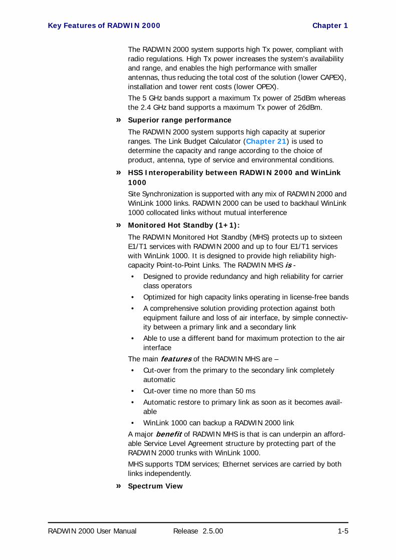
Key Features of RADWIN 2000 Chapter 1
RADWIN 2000 User Manual Release 2.5.00 1-5
The RADWIN 2000 system supports high Tx power, compliant with radio regulations. High Tx power increases the system's availability and range, and enables the high performance with smaller antennas, thus reducing the total cost of the solution (lower CAPEX), installation and tower rent costs (lower OPEX). The 5 GHz bands support a maximum Tx power of 25dBm whereas the 2.4 GHz band supports a maximum Tx power of 26dBm.
» Superior range performance
The RADWIN 2000 system supports high capacity at superior ranges. The Link Budget Calculator (Chapter 21) is used to determine the capacity and range according to the choice of product, antenna, type of service and environmental conditions.
» HSS Interoperability between RADWIN 2000 and WinLink 1000Site Synchronization is supported with any mix of RADWIN 2000 and WinLink 1000 links. RADWIN 2000 can be used to backhaul WinLink 1000 collocated links without mutual interference
» Monitored Hot Standby (1+1):
The RADWIN Monitored Hot Standby (MHS) protects up to sixteen E1/T1 services with RADWIN 2000 and up to four E1/T1 services with WinLink 1000. It is designed to provide high reliability high-capacity Point-to-Point Links. The RADWIN MHS is -• Designed to provide redundancy and high reliability for carrier
class operators• Optimized for high capacity links operating in license-free bands• A comprehensive solution providing protection against both
equipment failure and loss of air interface, by simple connectiv-ity between a primary link and a secondary link
• Able to use a different band for maximum protection to the air interface
The main features of the RADWIN MHS are – • Cut-over from the primary to the secondary link completely
automatic• Cut-over time no more than 50 ms• Automatic restore to primary link as soon as it becomes avail-
able• WinLink 1000 can backup a RADWIN 2000 link
A major benefit of RADWIN MHS is that is can underpin an afford-able Service Level Agreement structure by protecting part of the RADWIN 2000 trunks with WinLink 1000.MHS supports TDM services; Ethernet services are carried by both links independently.
» Spectrum View

Key Features of RADWIN 2000 Chapter 1
RADWIN 2000 User Manual Release 2.5.00 1-6
Spectrum View displays a visual representation of spectrum avail-ability during the link installation. It is an RF survey tool supporting the link installation prior to service activation.
Use Spectrum View to assist you to choose the operating channel.
» Diversity
RADWIN 2000 links using dual bipolar antennas may be configured to transmit the same data through both radios. This feature provides added data transmission integrity under harsh conditions.
» Simple installation and management
RADWIN 2000 systems are extremely simple to install and maintain. They are typically up and running in less than an hour.
The RADWIN Manager application has full local and remote management capabilities. The user-friendly SNMP based management tool provides full end-to-end configuration, event logging, and performance monitoring capabilities.
» Enhanced Security
The security features of RADWIN 2000 include:
• RADWIN 2000's AES 128-bit integrated advanced encryption support provides enhanced air interface security for carriers and private networks. It ensures user data protection with one of the most sophisticated commercially available combined encryption and authentication techniques, CCM/AES. This tech-nique combines message authentication (preventing anti-spoof-ing and replay protection) with commercial encryption, and complies with the IEEE 802.11i (phase iii) security recommen-dations.
CCM/AES uses a symmetric 128-bit encryption key (EK), and a nonce, and provides both message encryption and authenticat-ing signature. The nonce mechanism enables the receiver to remember already received genuine messages and reject all replayed messages.
• Initial encryption and authentication is based on a user-defined master key (Link Password). While standard Wireless LAN encrypts only the Ethernet Payload, the AES encrypts both the source and destination MAC addresses.
• In addition to normal log on access, Read or Write Community access is available at log on
• Link Lock is a part of the RADWIN 2000 security concept. It is designed to discourage physical theft of units and “piggyback-ing” using an otherwise identical ODU to steal bandwidth or information. It locks a pair of synchronized ODUs for mutually exclusive communication.
» SFP support in the IDU-C
Standard SFP modules are used, enabling any type of Ethernet phys-ical connectivity including various fiber connections. E3/T3 or E1/T1 over Ethernet SFPs can be used as well.

Components of a RADWIN 2000 Link Chapter 1
RADWIN 2000 User Manual Release 2.5.00 1-7
» Separate management and traffic VLAN support
» Ethernet Ring Topology
» QoS Support (RADWIN 2000 C based links)
QoS enables Operator and Service Providers to offer delay-sensitive services such as VoIP, IP-TV, time critical applications and online games.
Components of a RADWIN 2000 Link
The Outdoor Unit (ODU)The Radio Outdoor Unit (ODU)
The ODU is the radio transceiver of the RADWIN 2000 system. It supports two antennas for MIMO operation. It is available with an integrated antenna (Integrated Antenna ODU) or with connectors for an external antenna (Connectorized ODU).
The ODU may be mounted on a pole or a wall, and connects to the IDU or PoE device using a CAT5e cable.
The ODU comes in two form factors as shown in Figure 1-4 below:
Figure 1-4: ODU Form Factors
• Integrated Antenna ODUThis ODU has an integrated 370mm (1.2ft) flat panel antenna. The ODU contains both the radio and the antenna as a single unit housed in a weatherproof case.
Front Rear
Conn
ecto
rized
Inte
grat
ed A
nten
na

The Indoor Unit (IDU) Chapter 1
RADWIN 2000 User Manual Release 2.5.00 1-8
• Connectorized ODUThis ODU has 2xN-type connectors for connecting an external antenna.
The Indoor Unit (IDU)The IDU has the service ports and provides aggregation of these services towards the ODU that transports them over the air. The IDU also provides power to the ODU.
New style IDU-E for both WinLink 1000 and RADWIN 2000The new style IDU-E is a carrier grade, compact, half 19 inch wide, 1U plas-tic unit, providing up to two Ethernet ports and up to two E1/T1 interfaces. It offers Layer 2 support for Ethernet service and HSS support for collocated links. It is a low cost unit intended for both Access applications and Enter-prise use.
Figure 1-5: New style IDU-E - front view (Note new HSS LED on the left)
The IDU-E rear panel (right to left) has a 25 pin Dry Contact Alarms port. the two (or no) trunk ports, two LAN ports, an ODU port and finally a 3 pin DC power plug identical to that used on the IDU-C.
.
Figure 1-6: New style IDU-E: Rear panel
Note
See the RADWIN Product Catalog for the range of ODU products available in release 2.5.00.
The external antenna choices are:
• Single bipolar antenna• Two monopolar antennas• Single monopolar antenna

Power Over Ethernet (PoE) Devices Chapter 1
RADWIN 2000 User Manual Release 2.5.00 1-9
IDU-CThe IDU-C is a carrier-class 19 inch, 1U unit, providing E1/T1 ports, Ethernet ports, an SFP port, a STANDBY port for MHS control, dry contact alarms and indication LEDs. It has two DC power feed connectors. An AC to DC converter is available for powering the IDU-C from an AC source. The IDU-C is designed to be rack mounted.
Four IDU-C products are available in release 2.5.00 with 16, 8 and 4 E1/T1 ports and with Ethernet only ports.
Figure 1-7: IDU-C, Ethernet only, front panel
Figure 1-8: IDU-C, 16 E1/T1 ports, front panel
Power Over Ethernet (PoE) DevicesBasic PoE Device
The basic PoE device provides Ethernet ser-vice only, with power for the ODU. The PoE device is extremely compact, having one Ethernet port, one ODU port and a standard 3 pin male AC power socket.
It may be used with both WinLink 1000 and RADWIN 2000 radios.
Figure 1-9: Basic PoE device - showing the radio Ethernet port
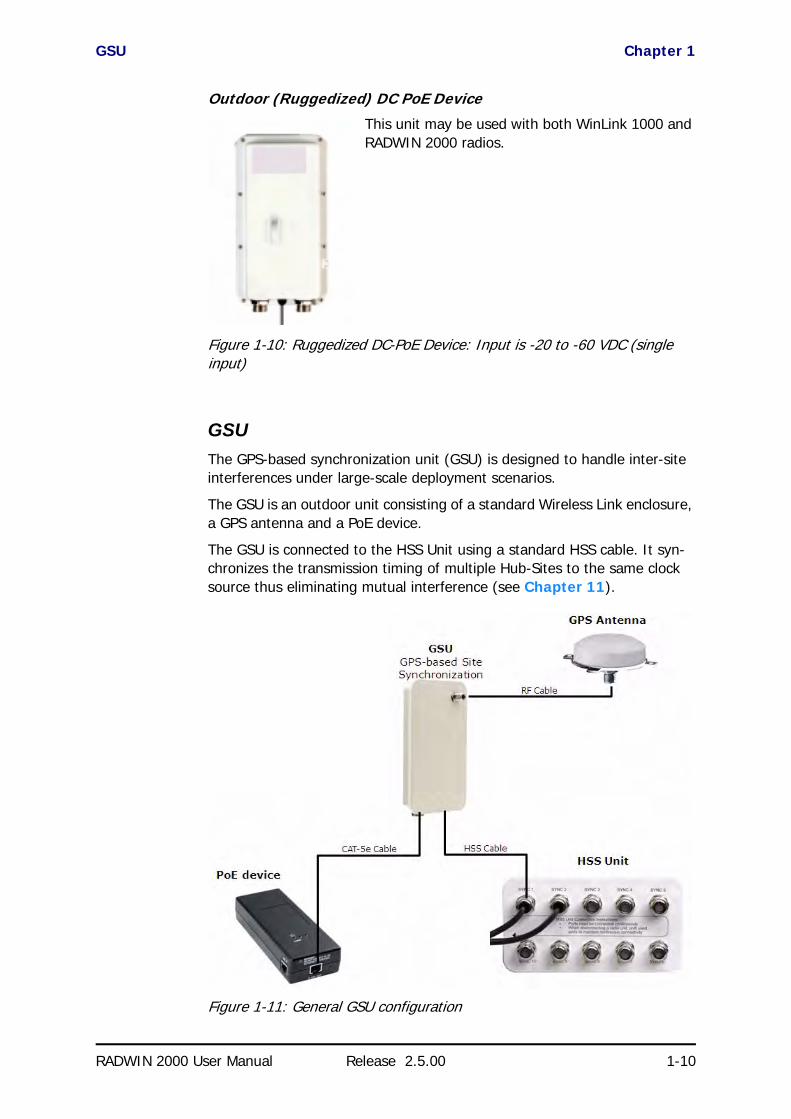
GSU Chapter 1
RADWIN 2000 User Manual Release 2.5.00 1-10
Outdoor (Ruggedized) DC PoE Device
This unit may be used with both WinLink 1000 and RADWIN 2000 radios.
Figure 1-10: Ruggedized DC-PoE Device: Input is -20 to -60 VDC (single input)
GSUThe GPS-based synchronization unit (GSU) is designed to handle inter-site interferences under large-scale deployment scenarios.
The GSU is an outdoor unit consisting of a standard Wireless Link enclosure, a GPS antenna and a PoE device.
The GSU is connected to the HSS Unit using a standard HSS cable. It syn-chronizes the transmission timing of multiple Hub-Sites to the same clock source thus eliminating mutual interference (see Chapter 11).
Figure 1-11: General GSU configuration
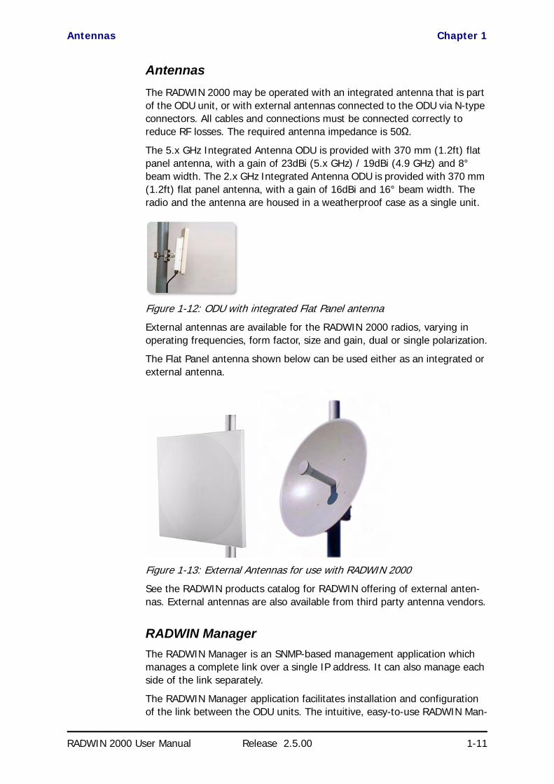
Antennas Chapter 1
RADWIN 2000 User Manual Release 2.5.00 1-11
AntennasAn antenna is the radiating and receiving element from which the radio signal, in the form of RF power, is radiated to its surroundings and vice versa. The antenna gain and transmitting power may be limited by country regulations.
The RADWIN 2000 may be operated with an integrated antenna that is part of the ODU unit, or with external antennas connected to the ODU via N-type connectors. All cables and connections must be connected correctly to reduce RF losses. The required antenna impedance is 50Ω.
The 5.x GHz Integrated Antenna ODU is provided with 370 mm (1.2ft) flat panel antenna, with a gain of 23dBi (5.x GHz) / 19dBi (4.9 GHz) and 8° beam width. The 2.x GHz Integrated Antenna ODU is provided with 370 mm (1.2ft) flat panel antenna, with a gain of 16dBi and 16° beam width. The radio and the antenna are housed in a weatherproof case as a single unit.
Figure 1-12: ODU with integrated Flat Panel antenna
External antennas are available for the RADWIN 2000 radios, varying in operating frequencies, form factor, size and gain, dual or single polarization.
The Flat Panel antenna shown below can be used either as an integrated or external antenna.
Figure 1-13: External Antennas for use with RADWIN 2000
See the RADWIN products catalog for RADWIN offering of external anten-nas. External antennas are also available from third party antenna vendors.
RADWIN ManagerThe RADWIN Manager is an SNMP-based management application which manages a complete link over a single IP address. It can also manage each side of the link separately.
The RADWIN Manager application facilitates installation and configuration of the link between the ODU units. The intuitive, easy-to-use RADWIN Man-

RADWIN Network Management System (RNMS) Chapter 1
RADWIN 2000 User Manual Release 2.5.00 1-12
ager has a graphical Microsoft Windows interface, and can be run locally and remotely.
The RADWIN Manager provides:
• Installation Wizard• Frequency band selection• On-line monitoring of air interface quality allowing the administrator
to monitor the service and status of each link• On-line monitoring of equipment alarms and QoS• Local and remote loopback testing
• Configuration Wizard and site settings• Integrated software upgrade utility
• On-line user manual and help files• Link Budget Calculator for calculating the expected performance of
the RADWIN 2000 wireless link and the possible service configura-tions for a specific link range.
The RADWIN Manager can easily be integrated with any SNMP based NMS system.
Figure 1-14: RADWIN Manager window
RADWIN Network Management System (RNMS)The RADWIN Network Management System enables Service Providers to manage all RADWIN links in their network from a Network Operations Cen-ter (NOC).
Using RNMS, Service Providers can configure and monitor up to 10,000 RADWIN links. The intuitive easy-to-use RNMS provides a full range of net-work surveillance, monitoring, configuration and fault management capabil-

Accessories Chapter 1
RADWIN 2000 User Manual Release 2.5.00 1-13
ities. It offers users complete visibility and control over their RADWIN-based networks.
AccessoriesRADWIN provides a variety of accessories to support the RADWIN 2000 sys-tem:
• PoE devices• AC Power Adaptors
• External Lightning Protection Units• Cables to connect the various system elements
• Grounding cables
Documentation supplied with RADWIN 2000The technical documentation supplied with a RADWIN 2000, is located on the product CD. It includes the following items:
• A Quick Installation Guide for experienced installers (also hardcopy)• A full User Manual - the document which you are reading
• A Help file accessible from the RADWIN Manager• Link Budget Calculator
How to Use this ManualThis User Manual is divided into three functionally distinct sections reflecting the activities required to set up a RADWIN 2000. The division is shown in the following table:
The Basic Installation section is divided into functionally distinct chapters reflecting the activities required to set up a RADWIN 2000. The division is shown in the following table:
Table 1-1: User Manual - General layout
Section General Content Purpose
1 Basic Installation Core information to install and operate a link
2 Advanced Installation Specialized installation techniques
3 Technical Information Background for advanced use
Table 1-2: User Manual layout
Chapter/Appendix Subject Audience
2 Site Preparation Site survey team
3 Hardware Installation Field technician
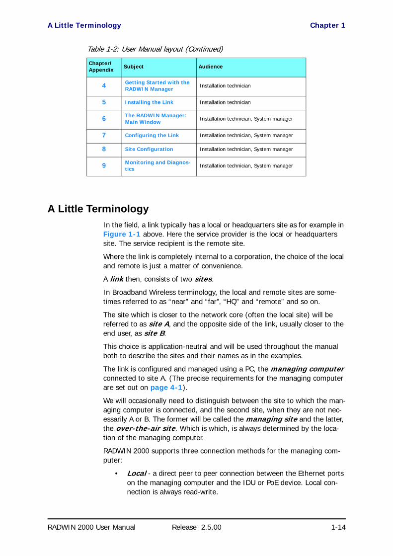
A Little Terminology Chapter 1
RADWIN 2000 User Manual Release 2.5.00 1-14
A Little TerminologyIn the field, a link typically has a local or headquarters site as for example in Figure 1-1 above. Here the service provider is the local or headquarters site. The service recipient is the remote site.
Where the link is completely internal to a corporation, the choice of the local and remote is just a matter of convenience.
A link then, consists of two sites.
In Broadband Wireless terminology, the local and remote sites are some-times referred to as “near” and “far”, “HQ” and “remote” and so on.
The site which is closer to the network core (often the local site) will be referred to as site A, and the opposite side of the link, usually closer to the end user, as site B.
This choice is application-neutral and will be used throughout the manual both to describe the sites and their names as in the examples.
The link is configured and managed using a PC, the managing computer connected to site A. (The precise requirements for the managing computer are set out on page 4-1).
We will occasionally need to distinguish between the site to which the man-aging computer is connected, and the second site, when they are not nec-essarily A or B. The former will be called the managing site and the latter, the over-the-air site. Which is which, is always determined by the loca-tion of the managing computer.
RADWIN 2000 supports three connection methods for the managing com-puter:
• Local - a direct peer to peer connection between the Ethernet ports on the managing computer and the IDU or PoE device. Local con-nection is always read-write.
4 Getting Started with the RADWIN Manager Installation technician
5 Installing the Link Installation technician
6 The RADWIN Manager: Main Window Installation technician, System manager
7 Configuring the Link Installation technician, System manager
8 Site Configuration Installation technician, System manager
9 Monitoring and Diagnos-tics Installation technician, System manager
Table 1-2: User Manual layout (Continued)
Chapter/Appendix Subject Audience

Conventions Used in this Manual Chapter 1
RADWIN 2000 User Manual Release 2.5.00 1-15
• Network - the managing computer and the site A IDU or PoE device belong to a LAN and communicate through a router or switch
• Over-the-air - the managing computer connects to site B via the air interface
• The managing computer may be connected to the link through an IDU or a PoE device. In what follows, where ever we refer to an IDU it includes PoE devices unless stated otherwise. Typically, if we need to refer to an IDU as such, we will use a model name such as IDU-C.
The terms uplink and downlink, originate from the field of Satellite com-munications. In a backhaul or ISP context, uplink is from the user to the network and downlink is from the network to the user.
Conventions Used in this Manual
NotificationsNotifications consist of Notes, Cautions and Warnings.
Typographical conventionsGeneralWhere a term is defined or introduced for the first time, it is shown in Bold-face. You will have noticed this usage in the Terminology section above.
Note
The purpose of a Note is to
• Draw your attention to something that may not be obvious or coun-ter-intuitive
• Emphasize a special feature or peculiarity of the RADWIN 2000• Offer an external reference for additional information• Add a caveat that would not qualify as a full Caution or Warning (see
below)• Provide additional background to what follows• Offer a recommendation• Highlight an indication of something to watch out for• Advise you if an action has “side effects” i.e. it may disturb something
else that would be best left undisturbed• Remind you of something that should be kept in mind
Caution
A Caution is a notification of risk of damage to equipment or of service degradation
Warning
A Warning is a notification of risk of danger to persons operating near the equipment

Windows Terminology Chapter 1
RADWIN 2000 User Manual Release 2.5.00 1-16
SoftwareThe RADWIN Manager is a Microsoft Windows application following the user interface conventions of familiar Microsoft Windows programs.
We would describe the chain of menu commands indicated in the navigation example of Figure 1-15 like this,
Tools|Active Alarms|1 A
using Boldface for the menu labels and vertical bars to separate them.
Figure 1-15: Menu navigation in the RADWIN Manager
Similarly, mouse click items will be referred to like this:
“Click Next to continue.”
(A mouse click always uses the left mouse button unless stated otherwise.)
Windows TerminologyLook at Figure 1-1 above. The main application display which you see con-sists of a frame-window with a menu bar, system icons and content. It will be referred to as a window, the main window or the Manager window depending on context.
The top line of icons is the tool bar, and provides part of the menu bar functionality with a mouse click.
At the bottom of the window is the status bar, a line of icons and text boxes.
The central part of the main window consists of several panes: On the right, there are Radio Interference, Ethernet Service and the Frequency panes. The left hand pane (with the blue background) is split into three sub-panes.
If you click Site A or Site B in the tool bar, you will be offered another win-dow, which in turn displays on of several panels depending on which func-tion you choose.

Viewing and Printing Chapter 1
RADWIN 2000 User Manual Release 2.5.00 1-17
Figure 1-16: Site Configuration window with open Management panel
Viewing and PrintingThis manual is optimized for viewing online as a PDF file. To this end it uses an 11 point Tahoma typeface for main text. Tables for most part, use 7 or 8 point fonts. Here are a few pointers for hard-copy printing:
• The text and table typefaces used are large enough to print the manual at two pages per sheet
• For good legibility, use a commercial grade laser printer. A color printer is of course best, however a monochrome printer set to use gray-scale gives acceptable results
• Better quality inkjet printers also give good output

RADWIN 2000 User Manual Release 2.5.00 2-1
Chapter 2
Installing the LinkOverview
The installation is carried out using the Installation wizard. Its operation is detailed in the following pages in a tutorial style.
For the purpose of explanation, we will set up a laboratory link with the fol-lowing characteristics:
• Channel selection: Automatic
• Antennas: Dual at both sites• Services: Ethernet + 7xE1 on ports 1, 2, 3, 8, 10, 11, 14. It is
unlikely that you would use a non-contiguous set of ports - but this shows that if required, it can be done.
The Installation wizard has steps as shown in Table 2-1 below.
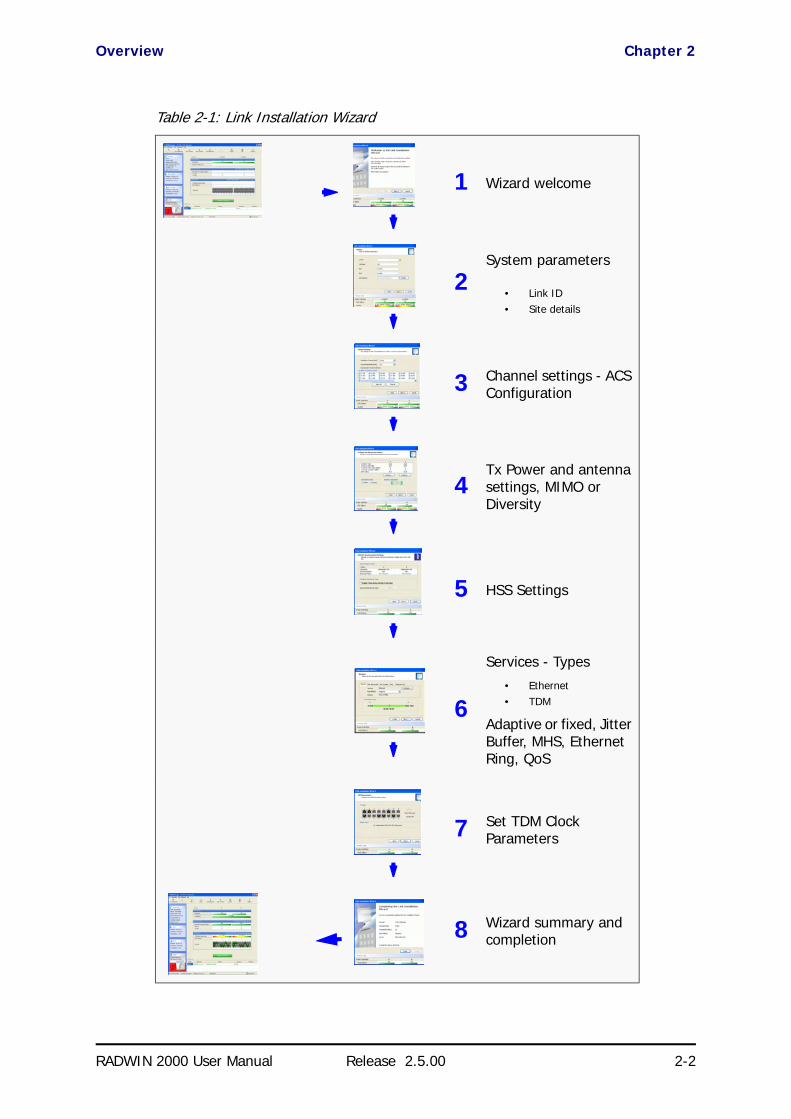
Overview Chapter 2
RADWIN 2000 User Manual Release 2.5.00 2-2
Table 2-1: Link Installation Wizard
1 Wizard welcome
2System parameters
• Link ID• Site details
3 Channel settings - ACS Configuration
4Tx Power and antenna settings, MIMO or Diversity
5 HSS Settings
6
Services - Types• Ethernet• TDM
Adaptive or fixed, Jitter Buffer, MHS, Ethernet Ring, QoS
7 Set TDM Clock Parameters
8 Wizard summary and completion

Installation Chapter 2
RADWIN 2000 User Manual Release 2.5.00 2-3
Installation
Step 1, Start the WizardIn the tool bar of the RADWIN Manager main window, click the Link Installation button. The Link Installation button is only accessible if the antennas are properly aligned. If this box is “grayed out”, you should align the antennas as set out in Chapter 3 on page 3-17.
The Installation Wizard opens:
Figure 2-1: Link Installation Wizard
The bottom data area reproduces the corresponding data from the main window - which the above panel obscures. See Chapter 6 for a field by field description of this data area.
Click Next to proceed with the installation procedure.
Step 2, System ParametersThe system dialog box opens:
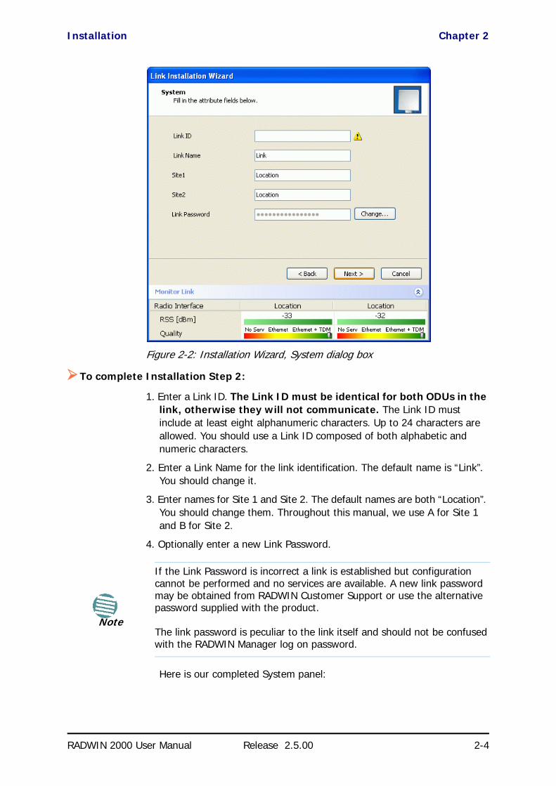
Installation Chapter 2
RADWIN 2000 User Manual Release 2.5.00 2-4
Figure 2-2: Installation Wizard, System dialog box
To complete Installation Step 2:
1. Enter a Link ID. The Link ID must be identical for both ODUs in the link, otherwise they will not communicate. The Link ID must include at least eight alphanumeric characters. Up to 24 characters are allowed. You should use a Link ID composed of both alphabetic and numeric characters.
2. Enter a Link Name for the link identification. The default name is “Link”. You should change it.
3. Enter names for Site 1 and Site 2. The default names are both “Location”. You should change them. Throughout this manual, we use A for Site 1 and B for Site 2.
4. Optionally enter a new Link Password.
Here is our completed System panel:
Note
If the Link Password is incorrect a link is established but configuration cannot be performed and no services are available. A new link password may be obtained from RADWIN Customer Support or use the alternative password supplied with the product.
The link password is peculiar to the link itself and should not be confused with the RADWIN Manager log on password.

Installation Chapter 2
RADWIN 2000 User Manual Release 2.5.00 2-5
Figure 2-3: Installation Wizard, System dialog box filled out
5. Click Next.
The default link with a rate of 6.5 Mbps is evaluated.
The Channel Setting dialog box appears. Proceed to Channel Settings, below.
Changing the Link PasswordThe default password is wireless-bridge. Optionally, you can change the link password as explained here.
To change the link password:
1. Click the Change button in the System dialog box.
The Change Link Password dialog box opens.
NoteUse the Hide characters check box for maximum security

Installation Chapter 2
RADWIN 2000 User Manual Release 2.5.00 2-6
Figure 2-4: Change Link Password dialog box
2. Enter the current link password (The default link password for a new ODU is wireless-bridge).
If you have forgotten the Link Password, click the Forgotten Link Pass-word button. The following window is displayed:
Figure 2-5: Lost or forgotten Link Password recovery
Follow the instructions to use the Alternative Link Password, and click OK to finish. You are returned to the window in Figure 2-4 above. Continue with the next step.
3. Enter a new password.
4. Retype the new password in the Confirm field.
5. Click OK.
6. Click Yes when asked if you want to change the link password.
7. Click OK at the Password changed success message.
Note
• A link password must contain at least eight but no more than 16 characters excluding SPACE, TAB, and any of “>#@|*?;.”
• Restoring Factory Defaults returns the Link Password to wireless-bridge.
• If the link is inactive, then the link password may also be changed from the Site Configuration dialogs. See page 8-13.
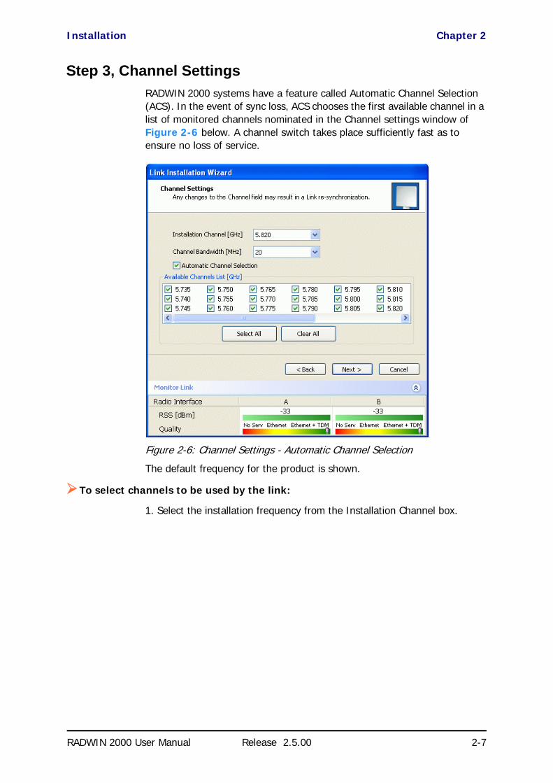
Installation Chapter 2
RADWIN 2000 User Manual Release 2.5.00 2-7
Step 3, Channel SettingsRADWIN 2000 systems have a feature called Automatic Channel Selection (ACS). In the event of sync loss, ACS chooses the first available channel in a list of monitored channels nominated in the Channel settings window of Figure 2-6 below. A channel switch takes place sufficiently fast as to ensure no loss of service.
Figure 2-6: Channel Settings - Automatic Channel Selection
The default frequency for the product is shown.
To select channels to be used by the link:
1. Select the installation frequency from the Installation Channel box.

Installation Chapter 2
RADWIN 2000 User Manual Release 2.5.00 2-8
Figure 2-7: Channel Settings - Showing available installation rates
2. Choose the required Channel Bandwidth.
Figure 2-8: Channel Settings - Showing available Channel Bandwidths
3. Click the check box if Automatic Channel Selection is required.
4. The Available Channels List contains all of the allowable channels for the link. Check the channels that can be automatically selected.

Installation Chapter 2
RADWIN 2000 User Manual Release 2.5.00 2-9
Selecting a new channel causes the system quality to change. The Qual-ity bar provides an indication of the link quality from No serv(ice) (red) to Ethernet + TDM (green) as shown in the bottom of Figure 2-7 above.
5. Click Next.
Step 4, Tx Power and Antenna SettingsThe Tx Power and Antenna Parameters dialog appears.
.
Figure 2-9: Transmission Power and Antenna Parameters
The choice of Tx Power, antenna gain and cable loss (between the radio and the antenna) determines the EIRP and is affected by such considerations as radio limitations and regulatory restrictions.
Before proceeding to antenna installation details, the following background information should be considered:
About Single and Dual AntennasEach RADWIN 2000 ODU is made of two radio transceivers (radios). The radios make use of algorithms that utilize both MIMO and Diversity resulting in enhanced capacity, range and link availability. The number of antennas (i.e. radios) used is determined by user configuration and by automatic sys-tem decisions, explained below.
Installation Chapter 2
RADWIN 2000 User Manual Release 2.5.00 2-10
Dual Antennas at Both SitesWhen using dual antennas at both sites (single bipolar antenna or two mo-unipolar antennas) you can choose between MIMO Mode and Diversity Mode.
MIMO Mode
With MIMO the system doubles the link capacity. At the same time, it keeps the same rate and modulation per radio as was used with single antenna, thus increasing capacity, range and availability.
For example with a dual antenna RADWIN 2000 can transmit at modulation of 64QAM and FEC of 5/6 and get an air rate of 130 Mbps, compared to 65 Mbps with single antenna.
To work in this mode, each antenna port must be connected to an antenna, the RSS level in both receivers should be balanced and a minimal separation between the antennas must be maintained. (For example, by using dual polarization antennas a cross polarization separation is attained).
Upon selecting Antenna Type as Dual, RADWIN 2000 automatically selects MIMO mode and doubles the air rates.
RADWIN Manager indicates a case of unbalanced RSS between the two antennas.
Diversity Mode
Diversity Mode uses two antennas to improve the quality and reliability of the link. Often, there is not a clear line-of-sight (LOS) between transmitter and receiver. Instead the signal is reflected along multiple paths before if-ally being received.
Each such “bounce” can introduce phase shifts, time delays, attenuations, and even distortions that can destructively interfere with one another at the aperture of the receiving antenna. Antenna diversity is especially effective at mitigating these multi-path situations.
This is because multiple antennas afford a receiver several recordings of the same signal. Each antenna will be exposed to a different interference envy-remnant. Thus, if one antenna is undergoing a deep fade, it is likely that another has a sufficient signal. Collectively such a system can provide a or-bust link.
Antenna diversity requires antenna separation which is possible by using a dual-polarization antenna or by two spatially separated antennas.
Use Diversity instead of MIMO in the following situations:
• When the system cannot operate in MIMO Mode• When one of the receivers has high interference compared to the
second receiver (i.e. the system is “unbalanced”)
• When you achieve higher capacity in Diversity Mode than in MIMO Mode
• When high robustness is of importance and the capacity of Diversity Mode is sufficient (up to 25 Mbps full duplex)

Installation Chapter 2
RADWIN 2000 User Manual Release 2.5.00 2-11
Single Antennas at Both SitesBy selecting a single antenna at both sites the ODUs operate with a single radio that is connected to the ANT 1 connector. The second radio is auto-matically shut down.
Single at One Site, Dual Antennas at the OtherIn this mode one of the sites uses the ODU with a single antenna while the other site uses the ODU with a dual antenna.
The advantages in this mode in comparison to using a single antenna in both sites are doubled total Tx Power and additional polarization and/or space diversity (depending on the polarization of installed antennas).
The air rates used in this mode are same as when using single antennas in both sites.
Table 2-2 summarizes the situation:
The rates used by RADWIN 2000 are shown in Table 2-3 below:
Table 2-2: MIMO - Diversity settings
Number of Antennas Mode Graphic Indication
Max Full Duplex
CapacitySite A Site B
2 2
MIMO 50 Mbps
Diversity 25 Mbps
2 1 25 Mbps
1 2 25 Mbps
1 1 25 Mbps
Table 2-3: RADWIN 2000 Air rates
Antenna Modulation FEC Air-Rate [Mbps]
Single BPSK 1/2 6.5
Single QPSK 1/2 13
Single QPSK 3/4 19.5
Single 16QAM 1/2 26
Single 16QAM 3/4 39
Single 64QAM 2/3 52

Installation Chapter 2
RADWIN 2000 User Manual Release 2.5.00 2-12
Considerations for Changing Antenna ParametersLet:
max Available Tx Power denote the maximum Tx Power practically available from an ODU. It appears as Tx Power per Radio in Figure 2-10 below.
maxRegEIRP denote the maximum EIRP available by regulation. It will be determined by three factors:
• per band/regulation• per channel bandwidth
• antenna gain
It appears in Figure 2-10 as Max EIRP.
maxRegTxPower denote the maximum regulatory Tx Power for the equipment, also having regard the above three points.
Then, the following relationship must be satisfied: ... (*)
These parameters are controlled as follows:
To set Tx Power and configure antennas:
1. Click the Configure buttons in turn to configure the antennas on both sides of the link. Each one offers a dialog like this:
Single 64QAM 3/4 58.5
Single 64QAM 5/6 65
Dual BPSK 1/2 13
Dual QPSK 1/2 26
Dual QPSK 3/4 39
Dual 16QAM 1/2 52
Dual 16QAM 3/4 78
Dual 64QAM 2/3 104
Dual 64QAM 3/4 117
Dual 64QAM 5/6 130
Table 2-3: RADWIN 2000 Air rates (Continued)
Antenna Modulation FEC Air-Rate [Mbps]
maxAvailableTxPower min maxRegEIRPAntennaGain CableLoss maxRegTxPower,+–
()
≤
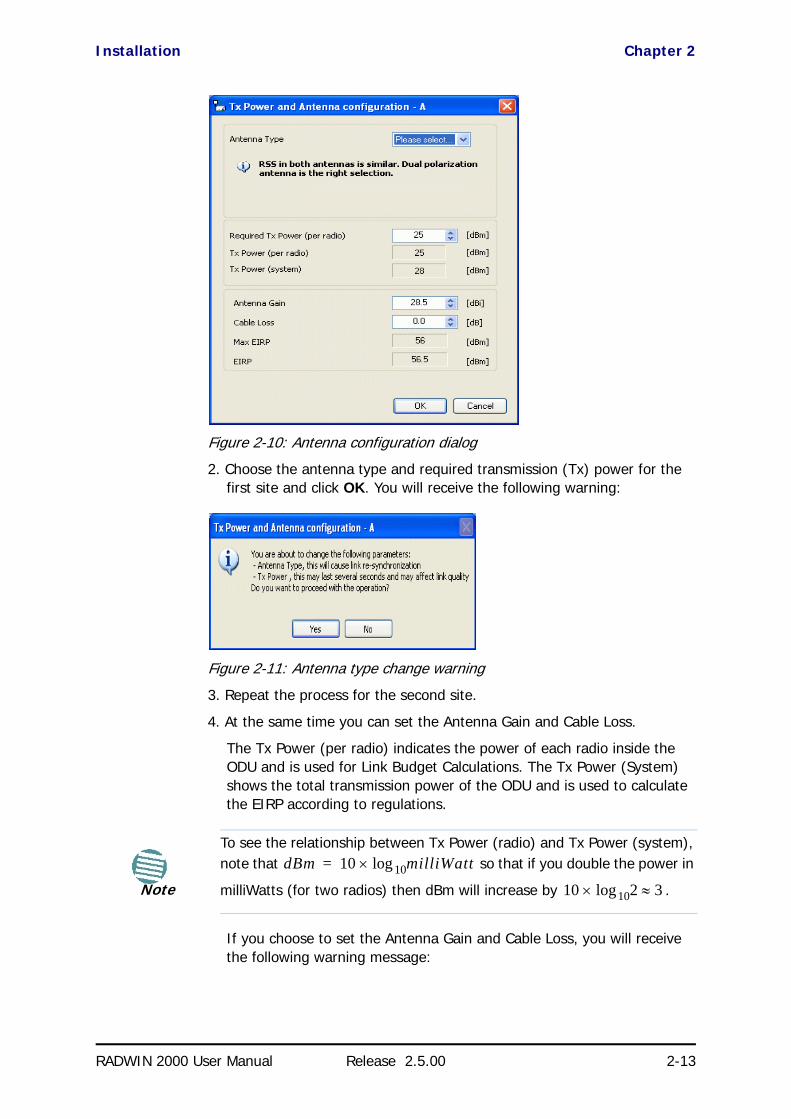
Installation Chapter 2
RADWIN 2000 User Manual Release 2.5.00 2-13
Figure 2-10: Antenna configuration dialog
2. Choose the antenna type and required transmission (Tx) power for the first site and click OK. You will receive the following warning:
Figure 2-11: Antenna type change warning
3. Repeat the process for the second site.
4. At the same time you can set the Antenna Gain and Cable Loss.
The Tx Power (per radio) indicates the power of each radio inside the ODU and is used for Link Budget Calculations. The Tx Power (System) shows the total transmission power of the ODU and is used to calculate the EIRP according to regulations.
If you choose to set the Antenna Gain and Cable Loss, you will receive the following warning message:
Note
To see the relationship between Tx Power (radio) and Tx Power (system), note that so that if you double the power in
milliWatts (for two radios) then dBm will increase by .
dBm 10 milliWatt10log×=
10 2 3≈10log×

Installation Chapter 2
RADWIN 2000 User Manual Release 2.5.00 2-14
Figure 2-12: Antenna parameters change warning
If inequality (*) above is violated, then the following warning window is displayed:
Figure 2-13: Tx Power Limits
The precise relationship between the items in inequality (*) and the win-dow of Figure 2-10 is as follows:
• Required Tx Power (per radio) will be adjusted down to the lesser of the value entered and maxAvailableTxPower
• Tx Power (system) is maxAvailableTxPower + 3 (for 2 radios)
• Max EIRP is maxRegEIRP.
• EIRP is maxAvailableTx Power + Antenna Gain - Cable Loss
The table in Figure 2-13 only shows rates where the maximum Tx Power is the limitation, rather than regulations. When you close the win-
Note
• The Max EIRP level will be automatically set according to the selected band and regulation.
• The EIRP level is the sum of the System Tx Power and the Antenna Gain minus the Cable Loss.

Installation Chapter 2
RADWIN 2000 User Manual Release 2.5.00 2-15
dow of Figure 2-13, the change you requested will not be honored, and you will need to try again.
Figure 2-14: Antennas configured for two dual and Tx power 5 dBm
5. Choose Dual Antenna mode if appropriate. The green Antenna Configura-tion diagram indicates the active state. For dual antennas in Diversity mode it looks like this:
There are intermediate modes available for dual antennas opposite a sin-gle antenna as set out on page 2-9 above.
If you make a change you will see a warning similar to this:
Note
Since our demonstration link is entirely indoors, we have reduced Tx Power to 5 dBm to obtain a realistic RSS. Although this is much too low for field use, the method is general.
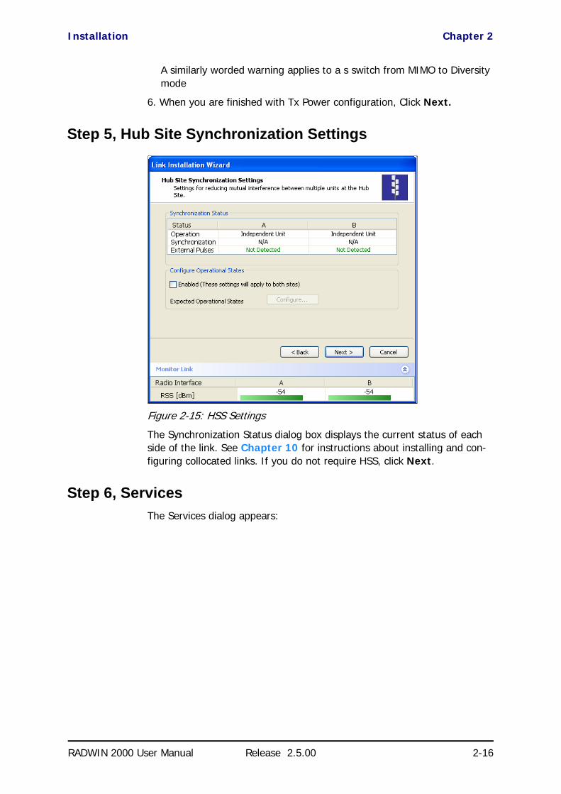
Installation Chapter 2
RADWIN 2000 User Manual Release 2.5.00 2-16
A similarly worded warning applies to a s switch from MIMO to Diversity mode
6. When you are finished with Tx Power configuration, Click Next.
Step 5, Hub Site Synchronization Settings
Figure 2-15: HSS Settings
The Synchronization Status dialog box displays the current status of each side of the link. See Chapter 10 for instructions about installing and con-figuring collocated links. If you do not require HSS, click Next.
Step 6, ServicesThe Services dialog appears:
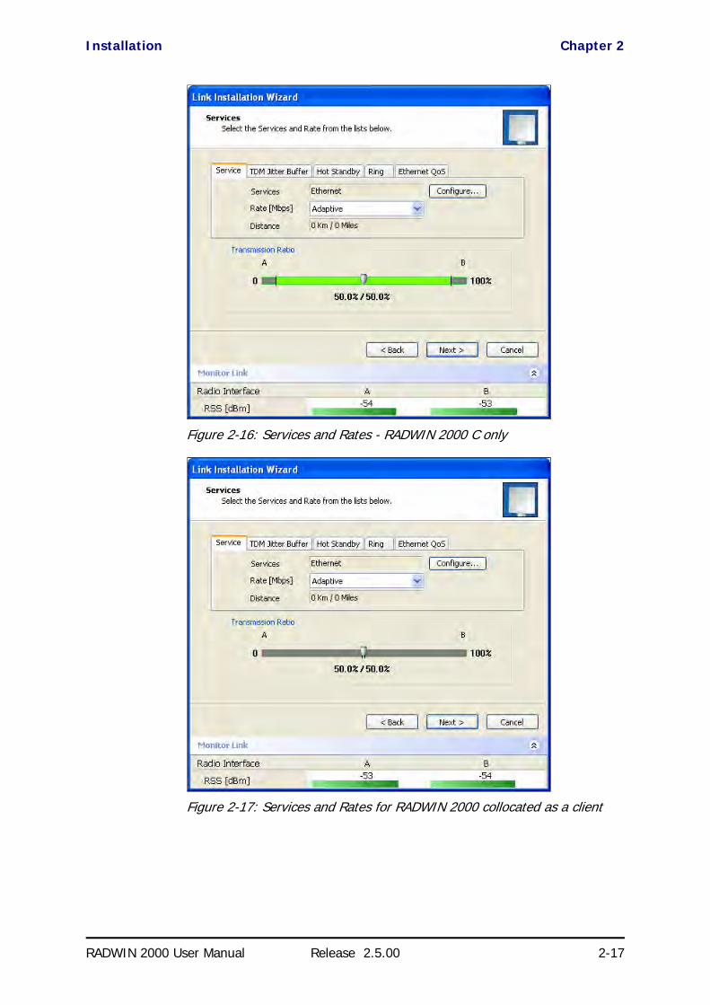
Installation Chapter 2
RADWIN 2000 User Manual Release 2.5.00 2-17
Figure 2-16: Services and Rates - RADWIN 2000 C only
Figure 2-17: Services and Rates for RADWIN 2000 collocated as a client
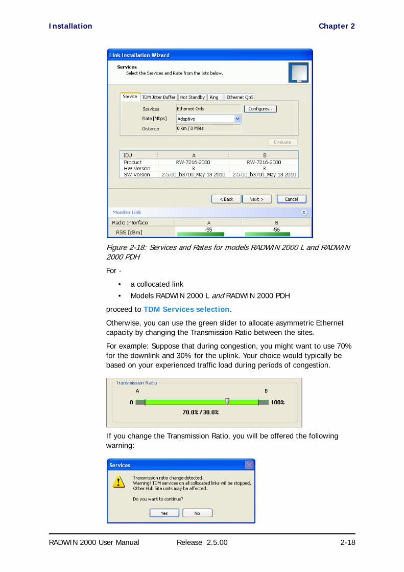
Installation Chapter 2
RADWIN 2000 User Manual Release 2.5.00 2-18
Figure 2-18: Services and Rates for models RADWIN 2000 L and RADWIN 2000 PDH
For -
• a collocated link• Models RADWIN 2000 L and RADWIN 2000 PDH
proceed to TDM Services selection.
Otherwise, you can use the green slider to allocate asymmetric Ethernet capacity by changing the Transmission Ratio between the sites.
For example: Suppose that during congestion, you might want to use 70% for the downlink and 30% for the uplink. Your choice would typically be based on your experienced traffic load during periods of congestion.
If you change the Transmission Ratio, you will be offered the following warning:

Installation Chapter 2
RADWIN 2000 User Manual Release 2.5.00 2-19
Otherwise, click Yes to continue.
Limitations on the use of Asymmetric AllocationFor non collocated links, capacity allocation between uplink and downlink traffic is determined automatically according to actual Ethernet traffic and air interface conditions. Your manual allocation using this feature “cuts in” during congestion.
Asymmetric Allocation and CollocationThe use of Asymmetric Allocation is limited where the link is collocated. Pos-sible scenarios are shown in Table 2-4. In all cases where Asymmetric Allo-cation is available, it is static for all traffic conditions.
The Services and Rates dialog as shown in Figure 2-16 will be different:
Caution
If you have active collocated links, or if you are uncertain of whether collocated links provide TDM services do not use this option now. You can do it at a less disruptive time using the Link Configuration (Chapter 7).
Table 2-4: Asymmetric Allocation with Collocated Links - Scenarios
HSS Master HSS Client Scenario: If you try to... Result Remarks
RADWIN 2000
WinLink 1000
Change master to asymmetric allocation
Link down Reversion to 50/50 restores link
RADWIN 2000
• Releases prior to 2.4 - Link down
• Release 2.4 later (RAD-WIN 2000 PDH and RADWIN 2000 L series) - Link down
• Release 2.4 and later (RADWIN 2000 C series) - TDM services stopped, link set to transmission ratio of master
Release 2.4 and later (RADWIN 2000 C series) - Asymmetric Allocation slider visible but cannot be changed
RADWIN 2000
WinLink 1000
RADWIN 2000Change client to asymmetric
Asymmetric Allocation slider not displayed
You cannot do this
WinLink 1000
WinLink 1000
RADWIN 2000Change client to asymmetric
Asymmetric Allocation slider not displayed
You cannot do this

Installation Chapter 2
RADWIN 2000 User Manual Release 2.5.00 2-20
Figure 2-19: Services and Rates - RADWIN 2000 C master, RADWIN 2000 clients
The yellow areas should not be used. Using those areas, you may loose the collocated link with the longest distance between sites.
Asymmetric Allocation and TDMYou cannot use this feature when TDM services are used. Selection of TDM ports as in the next section will reset the Ethernet balance to 50% in each direction and the green slider will not appear in subsequent Installation or Configuration runs.
Cancelling TDM port use will make the allocation bar reappear, re-enabling asymmetric Ethernet traffic allocation.
If you are not using TDM services, clicking Next will take you to Step 8, and completion of the installation. Your Ethernet capacity allocation will be reflected in Figure 2-34 below.
TDM Services selection
To select services:
1. Click the Configure button. The TDM services dialog is displayed:

Installation Chapter 2
RADWIN 2000 User Manual Release 2.5.00 2-21
Figure 2-20: TDM Type selection
2. Using the TDM Type radio buttons, choose E1 or T1. You are now able to select the required service ports:
Figure 2-21: TDM service port selection
3. Use the spin button to choose consecutive service ports, the Select Maximum button to choose all available ports or click on individual ports to choose them.
Note
• Ethernet is always selected.• The maximum available services will be reduced in accordance with
actual air interface capacity.
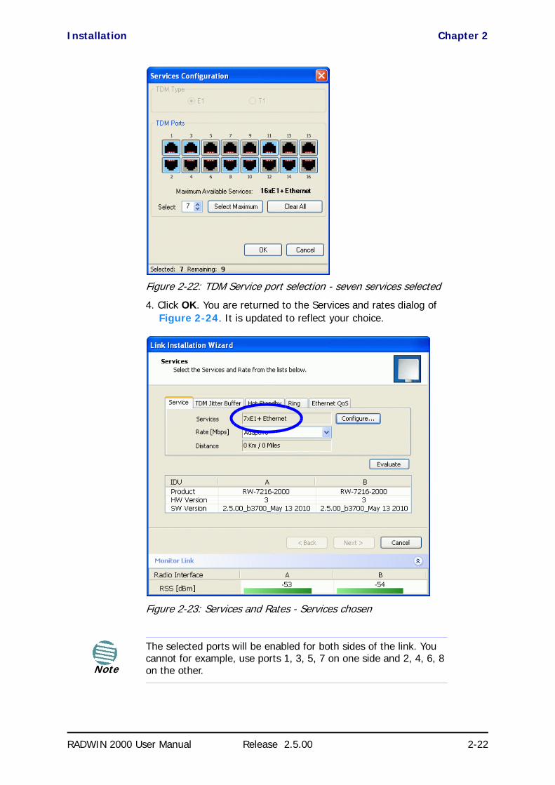
Installation Chapter 2
RADWIN 2000 User Manual Release 2.5.00 2-22
Figure 2-22: TDM Service port selection - seven services selected
4. Click OK. You are returned to the Services and rates dialog of Figure 2-24. It is updated to reflect your choice.
Figure 2-23: Services and Rates - Services chosen
Note
The selected ports will be enabled for both sides of the link. You cannot for example, use ports 1, 3, 5, 7 on one side and 2, 4, 6, 8 on the other.

Installation Chapter 2
RADWIN 2000 User Manual Release 2.5.00 2-23
Modulation Rate SelectionYou may choose a specific modulation rate or use Adaptive.
Figure 2-24: Services and Rates dialog: Available rates
To choose a modulation rate:
1. Choose Adaptive or one of the available rates.
2. Click Evaluate to continue or click the TDM Jitter Buffer tab to set the TDM Jitter Buffer (see next section).
The service is activated as show below:
You are returned to the Services and rates dialog of Figure 2-24.
Setting Monitored Hot Standby ModeIf you are not using Hot Standby Mode, you may skip this section.
To install and use the Hot Standby feature, see Chapter 12. The following procedure can be used to switch links between primary and secondary or to disable the mode.
To set the Hot Standby Mode:
1. Click the Hot Standby tab. The following dialog appears:
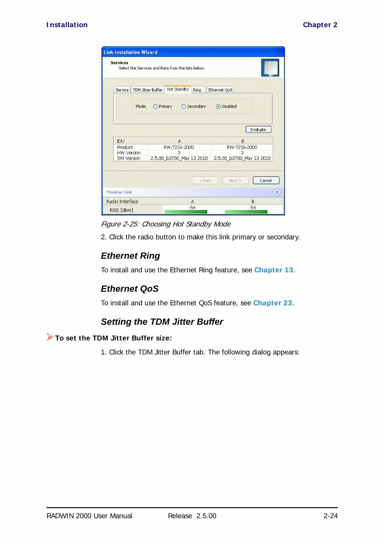
Installation Chapter 2
RADWIN 2000 User Manual Release 2.5.00 2-24
Figure 2-25: Choosing Hot Standby Mode
2. Click the radio button to make this link primary or secondary.
Ethernet RingTo install and use the Ethernet Ring feature, see Chapter 13.
Ethernet QoSTo install and use the Ethernet QoS feature, see Chapter 23.
Setting the TDM Jitter Buffer
To set the TDM Jitter Buffer size:
1. Click the TDM Jitter Buffer tab. The following dialog appears:

Installation Chapter 2
RADWIN 2000 User Manual Release 2.5.00 2-25
Figure 2-26: TDM Jitter Buffer Configuration
Note
• The receiver jitter buffer for each site can be enlarged, thereby increasing system resistance to interference (the larger the jitter buffer, the longer the interference period that the system will overcome without TDM errors).
• You can also decrease the jitter buffer to decrease the sys-tem delay.
• The jitter buffer can be configured between 2.0 and 16.0 ms.
• After setting the new value you must evaluate the expected quality. During the evaluation the TBFR (TDM Block Failure Ratio)bar is displayed. You select either Next, which per-forms the change or Back to cancel the change. Notice that the Jitter Buffer is configured per site.

Installation Chapter 2
RADWIN 2000 User Manual Release 2.5.00 2-26
Figure 2-27: TDM Jitter Buffer Configuration - TBFR evaluation bar
2. After setting the jitter buffer size, if grayed out, the Evaluate button is enabled while both Back and Next are disabled as shown in the next figure:
Figure 2-28: Services and TDM delay set - link ready for evaluation
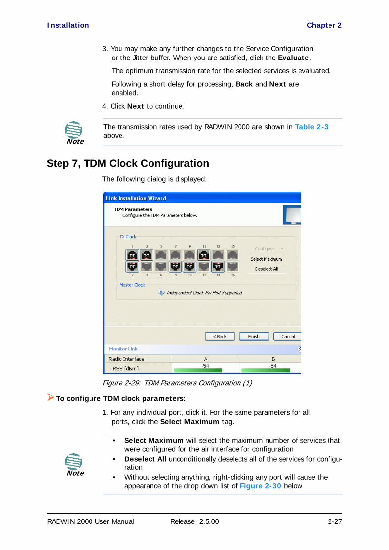
Installation Chapter 2
RADWIN 2000 User Manual Release 2.5.00 2-27
3. You may make any further changes to the Service Configuration or the Jitter buffer. When you are satisfied, click the Evaluate.
The optimum transmission rate for the selected services is evaluated.
Following a short delay for processing, Back and Next are enabled.
4. Click Next to continue.
Step 7, TDM Clock ConfigurationThe following dialog is displayed:
Figure 2-29: TDM Parameters Configuration (1)
To configure TDM clock parameters:
1. For any individual port, click it. For the same parameters for all ports, click the Select Maximum tag.
Note
The transmission rates used by RADWIN 2000 are shown in Table 2-3 above.
Note
• Select Maximum will select the maximum number of services that were configured for the air interface for configuration
• Deselect All unconditionally deselects all of the services for configu-ration
• Without selecting anything, right-clicking any port will cause the appearance of the drop down list of Figure 2-30 below

Installation Chapter 2
RADWIN 2000 User Manual Release 2.5.00 2-28
2. Click Configure. The following drop down list is displayed:
Figure 2-30: TDM Parameters Configuration (2)
3. Click the required parameter. Their meanings are as follows:
Figure 2-31: TDM Parameters
Transparent/Transparent
The clock at Site A regenerates the clock from Site B and vice versa.
Loop time/Recover
The Site A port receive-clock is used as the transmit-clock for that port on both sides of the link.
Recover/Loop time
The Site B port receive-clock is used as the transmit-clock for that port on both sides of the link.
Internal/Recover
NotePlease keep in mind that what follows is per port.
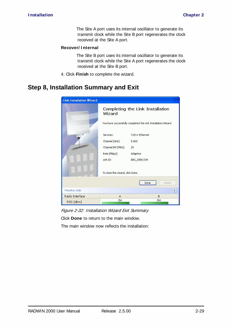
Installation Chapter 2
RADWIN 2000 User Manual Release 2.5.00 2-29
The Site A port uses its internal oscillator to generate its transmit clock while the Site B port regenerates the clock received at the Site A port.
Recover/Internal
The Site B port uses its internal oscillator to generate its transmit clock while the Site A port regenerates the clock received at the Site B port.
4. Click Finish to complete the wizard.
Step 8, Installation Summary and Exit
Figure 2-32: Installation Wizard Exit Summary
Click Done to return to the main window.
The main window now reflects the installation:
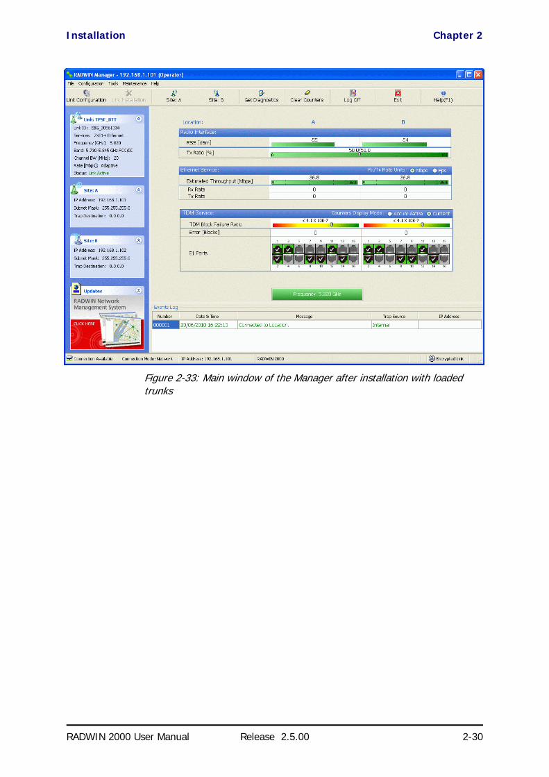
Installation Chapter 2
RADWIN 2000 User Manual Release 2.5.00 2-30
Figure 2-33: Main window of the Manager after installation with loaded trunks

Installation Chapter 2
RADWIN 2000 User Manual Release 2.5.00 2-31
Figure 2-34: Main window of the Manager after installation with asymmetric capacity allocation - No HSS
Figure 2-34 shows the results of a 70%/30% Transmission ratio on a lone link (no HSS). Observe that near 100Mbs is available in either direction

Installation Chapter 2
RADWIN 2000 User Manual Release 2.5.00 2-32
Figure 2-35: Main window of the Manager after installation with asymmetric capacity allocation - HSS enabled
Figure 2-35 shows the results of a 70%/30% Transmission ratio on a lone link with HSS. The allocation is “hard”.
To verify the installation:
• Verify that the Received Signal Strength (RSS) is according to expected results as determined by the Link Budget Calculator.
Caution
Installation mode, as described above, may be re-entered using Site:A or Site:B and Installation Mode in the Site Configuration dialog. Some Installation mode functionality may cause a break in, or degrade link service.
If you can accomplish link changes without affecting the service, always prefer to use Configuration mode, described in Chapter 7.

RADWIN 2000 User Manual Release 2.5.00 4-1
Chapter 4
Hardware InstallationThis chapter sets out the requirements and procedures for the hardware installation and alignment of a RADWIN 2000 link in accordance with the prior planning as set out in Chapter 2. It is intended to guide qualified field technicians.
Safety Practices
Preventing overexposure to RF energyTo protect against overexposure to RF energy, install the ODUs so as to pro-vide and maintain minimal separation distances from all persons.
When the system is operational, avoid standing directly in front of the antenna. Strong RF fields are present when the transmitter is on. The ODU must not be deployed in a location where it is possible for people to stand or walk inadvertently in front of the antenna.
GroundingAll RADWIN products should be grounded during operation. In addition:
• The ODU should be earthed by a wire with diameter of at least 12AWG.The RADWIN 2000 ODU must be properly grounded to protect against lightning. It is the user's responsibility to install the
Warning
Outdoor units and antennas should be installed ONLY by experienced installation professionals who are familiar with local building and safety codes and, wherever applicable, are licensed by the appropriate government regulatory authorities. Failure to do so may expose the end user or the service provider to legal and financial liabilities. RADWIN and its resellers or distributors are not liable for injury, damage or violation of regulations associated with the installation of outdoor units or antennas.
Note
The material in this chapter is generic to all RADWIN radio link products unless stated otherwise.

Protection against Lightning Chapter 4
RADWIN 2000 User Manual Release 2.5.00 4-2
equipment in accordance with Section 810 of the National Electric Code, ANSI/NFPA No.70-1984 or Section 54 of the Canadian Electrical Code. These codes describe correct installation procedures for grounding the outdoor unit, mast, lead-in wire and discharge unit. It also lays down the size of grounding conductors and connection requirements for grounding electrodes.
The RADWIN 2000 ODU must be grounded to a Protective Earth as described in Chapter 18 and in accordance with the Local Electrical Regulations.
• The earth lug on the IDU-C should be connected to the protective earth at all times, by a wire with a diameter of 18 AWG or wider. Rack-mounted equipment should be mounted only in earthed racks and cabinets.
Further, you should -
• Always make the ground connection first and disconnect it last• Never connect telecommunication cables to ungrounded equipment• Ensure that all other cables are disconnected before disconnecting
the ground
More detailed guidelines are supplied in Chapter 18.
Protection against LightningThe use of lightning protection is dependent on regulatory and end user requirements. All of RADWIN outdoor units are designed with surge limiting circuits to minimize the risk of damage due to lightning strikes. RADWIN recommends the use of additional surge arrestor devices to protect the equipment from nearby lightning strikes.
See Chapter 18 for detailed installation instructions of lightning protection devices.
General• It is recommended that installation of the outdoor unit be contracted
to a professional installer.
• Before working on equipment connected to power lines or telecom-munication lines, you should remove jewelry or any other metallic object that may come into contact with energized parts.
• Use extreme care when installing antennas near power lines.• Use extreme care when working at heights.• When using an AC power source for RADWIN 2000 always use the
AC power adapter supplied by RADWIN.• Use the right tools. In addition to standard tools required for any
kind of ODU or antenna installation, RADWIN 2000 requires addi-tional specific tools detailed on page 4-5 below.

Package Contents Chapter 4
RADWIN 2000 User Manual Release 2.5.00 4-3
Package ContentsThe RADWIN 2000 packages include the following items:
ODU Package ContentsThe ODU package contains:
• One ODU - see Figure 4-2 and Figure 4-3 below for front and rear view
• An ODU mounting kit - see Figure 4-1 below
• A CD containing -• the RADWIN Manager• Quick Start Guide
• User Manual - the document you are reading• Link Budget Calculator
• Label showing the MAC address and the alternative Community string. The label is self-adhesive. You should keep this label safe
• Cable glands (to be used with the ODU-IDU cable)
Figure 4-1: ODU Mounting kit
Figure 4-2: Connectorized ODU - Front and rear views
ODU - Front View ODU - Rear View

IDU-E package containing: Chapter 4
RADWIN 2000 User Manual Release 2.5.00 4-4
Figure 4-3: Integrated ODU - Front and rear views
IDU-E package containing:• IDU-E• AC/DC Converter
• IDU-E wall-mounting drilling template• Self adhesive label showing the IDU LED operation
Figure 4-4: IDU-E- front view
IDU-C Package ContentsThe IDU-c package contains:
• IDU-C - see Figure 4-5 below.• 19” rack mounting kit - see Figure 4-7 below
• Two DC power plugs for power cables - see Figure 4-7 below
Figure 4-5: IDU-C Package contents - the IDU-C, Ethernet only
ODU - Front View ODU - Rear View

External Antenna Package Contents Chapter 4
RADWIN 2000 User Manual Release 2.5.00 4-5
Figure 4-6: IDU-C Package contents - the IDU-C, 16 E1/T1 ports
Figure 4-7: IDU-C Package contents - the mounting kit and DC power plugs
External Antenna Package Contents• Antenna
• RF cable 1m (3’) long; two cables supplied with bipolar antennas, single cable supplied with monopolar antennas
• Mounting kit
Additional Tools and Materials RequiredThe following is a list of the equipment and materials required to install RADWIN 2000 hardware.
Tools and Materials• Crimping tool for RJ-45 (if the ODU-IDU cable is without connectors)• Spanner/wrench 13 mm (½”) • Drill (for wall mounting only)
• Cable ties• Sealing material
Cables and connectors• ODU grounding cable 12AWG• IDU grounding cable 18AWG
• ODU-IDU cable (outdoor class, CAT-5e, 4 twisted pairs, 24AWG)

Hardware Installation Sequence Chapter 4
RADWIN 2000 User Manual Release 2.5.00 4-6
• For PoE based links: A crossed Ethernet LAN cable
Hardware Installation SequenceThe following steps are required to install the RADWIN 2000 system:
1. Mounting the ODUs, page page 4-7.
2. Mounting the external antennas (if used), page page 4-7.
3. Mounting the Lightning Protection devices (if used), page page 4-8.
4. Outdoor connections, page page 4-8.
5. Mounting the IDUs, page page 4-9.
6. Indoor connections, page page 4-12.
7. Aligning the ODUs/antennas, page page 4-13.
See Figure 4-8 below, which illustrates a typical installation of a RADWIN 2000 or a WinLink 1000 with external antenna(s).
Figure 4-8: Typical Installation (with external antenna) Left: RADWIN 2000 Right: WinLink 1000
The installation steps are detailed in the following sections.
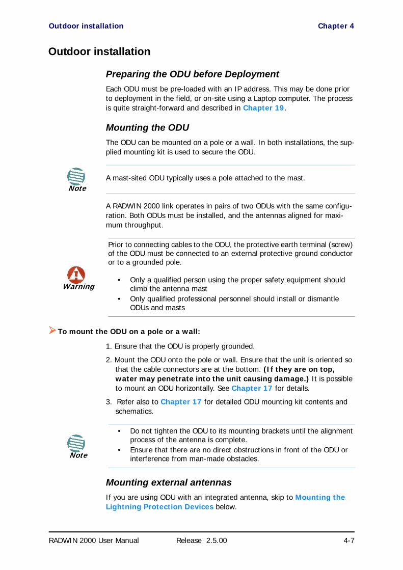
Outdoor installation Chapter 4
RADWIN 2000 User Manual Release 2.5.00 4-7
Outdoor installation
Preparing the ODU before DeploymentEach ODU must be pre-loaded with an IP address. This may be done prior to deployment in the field, or on-site using a Laptop computer. The process is quite straight-forward and described in Chapter 19.
Mounting the ODUThe ODU can be mounted on a pole or a wall. In both installations, the sup-plied mounting kit is used to secure the ODU.
A RADWIN 2000 link operates in pairs of two ODUs with the same configu-ration. Both ODUs must be installed, and the antennas aligned for maxi-mum throughput.
To mount the ODU on a pole or a wall:
1. Ensure that the ODU is properly grounded.
2. Mount the ODU onto the pole or wall. Ensure that the unit is oriented so that the cable connectors are at the bottom. (If they are on top, water may penetrate into the unit causing damage.) It is possible to mount an ODU horizontally. See Chapter 17 for details.
3. Refer also to Chapter 17 for detailed ODU mounting kit contents and schematics.
Mounting external antennasIf you are using ODU with an integrated antenna, skip to Mounting the Lightning Protection Devices below.
NoteA mast-sited ODU typically uses a pole attached to the mast.
Warning
Prior to connecting cables to the ODU, the protective earth terminal (screw) of the ODU must be connected to an external protective ground conductor or to a grounded pole.
• Only a qualified person using the proper safety equipment should climb the antenna mast
• Only qualified professional personnel should install or dismantle ODUs and masts
Note
• Do not tighten the ODU to its mounting brackets until the alignment process of the antenna is complete.
• Ensure that there are no direct obstructions in front of the ODU or interference from man-made obstacles.
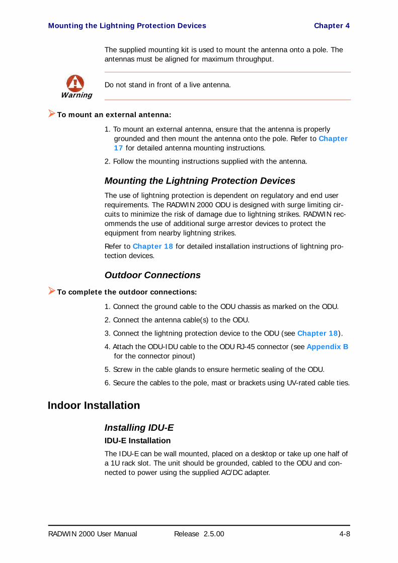
Mounting the Lightning Protection Devices Chapter 4
RADWIN 2000 User Manual Release 2.5.00 4-8
The supplied mounting kit is used to mount the antenna onto a pole. The antennas must be aligned for maximum throughput.
To mount an external antenna:
1. To mount an external antenna, ensure that the antenna is properly grounded and then mount the antenna onto the pole. Refer to Chapter 17 for detailed antenna mounting instructions.
2. Follow the mounting instructions supplied with the antenna.
Mounting the Lightning Protection DevicesThe use of lightning protection is dependent on regulatory and end user requirements. The RADWIN 2000 ODU is designed with surge limiting cir-cuits to minimize the risk of damage due to lightning strikes. RADWIN rec-ommends the use of additional surge arrestor devices to protect the equipment from nearby lightning strikes.
Refer to Chapter 18 for detailed installation instructions of lightning pro-tection devices.
Outdoor Connections
To complete the outdoor connections:
1. Connect the ground cable to the ODU chassis as marked on the ODU.
2. Connect the antenna cable(s) to the ODU.
3. Connect the lightning protection device to the ODU (see Chapter 18).
4. Attach the ODU-IDU cable to the ODU RJ-45 connector (see Appendix B for the connector pinout)
5. Screw in the cable glands to ensure hermetic sealing of the ODU.
6. Secure the cables to the pole, mast or brackets using UV-rated cable ties.
Indoor Installation
Installing IDU-E IDU-E InstallationThe IDU-E can be wall mounted, placed on a desktop or take up one half of a 1U rack slot. The unit should be grounded, cabled to the ODU and con-nected to power using the supplied AC/DC adapter.
WarningDo not stand in front of a live antenna.

Mounting the IDU-C Chapter 4
RADWIN 2000 User Manual Release 2.5.00 4-9
.
Figure 4-9: New style IDU-E: Rear panel
Mounting the IDU-CThe RADWIN 2000 IDU-As are all rack mountable, as shown in Figure 4-10. A front panel keyed schematic of a rack mounted IDU-C is shown in the figure below.
Figure 4-10: IDU-C front panel
In Figure 4-11 we display a perspective view of the IDU-C:
Figure 4-11: IDU-C - A perspective view
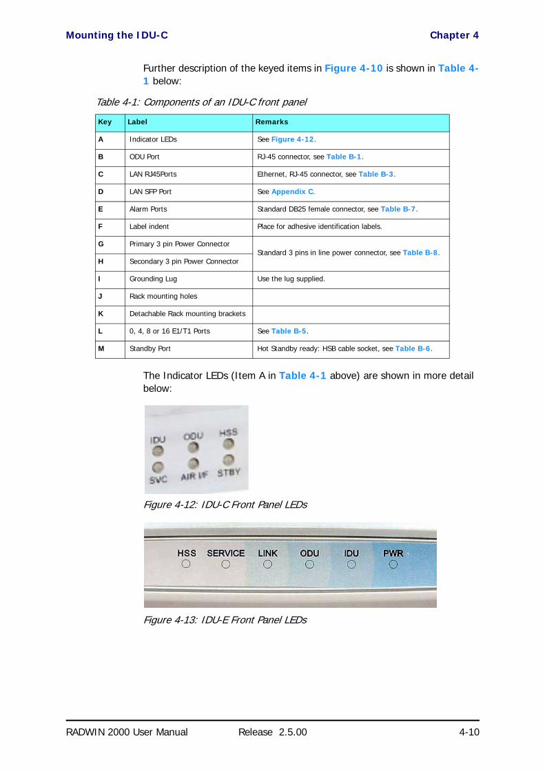
Mounting the IDU-C Chapter 4
RADWIN 2000 User Manual Release 2.5.00 4-10
Further description of the keyed items in Figure 4-10 is shown in Table 4-1 below:
The Indicator LEDs (Item A in Table 4-1 above) are shown in more detail below:
Figure 4-12: IDU-C Front Panel LEDs
Figure 4-13: IDU-E Front Panel LEDs
Table 4-1: Components of an IDU-C front panel
Key Label Remarks
A Indicator LEDs See Figure 4-12.
B ODU Port RJ-45 connector, see Table B-1.
C LAN RJ45Ports Ethernet, RJ-45 connector, see Table B-3.
D LAN SFP Port See Appendix C.
E Alarm Ports Standard DB25 female connector, see Table B-7.
F Label indent Place for adhesive identification labels.
G Primary 3 pin Power ConnectorStandard 3 pins in line power connector, see Table B-8.
H Secondary 3 pin Power Connector
I Grounding Lug Use the lug supplied.
J Rack mounting holes
K Detachable Rack mounting brackets
L 0, 4, 8 or 16 E1/T1 Ports See Table B-5.
M Standby Port Hot Standby ready: HSB cable socket, see Table B-6.

Mounting the IDU-C Chapter 4
RADWIN 2000 User Manual Release 2.5.00 4-11
The purpose of the LEDs is shown in Table 4-2 below:
To mount an IDU-C:
1. Attach the rack mounting brackets (K) to the IDU.
2. Bolt the IDU into an empty slot in the rack, ensuring that it sits securely.
Table 4-2: IDU-C Front Panel LEDs
Name Color Function
IDU
Green
Blinking Green
Red
Blinking Orange
IDU operational
During power-up only
Failure
During power-up; continues if ODU fails to load IDU firmware.
Also, when using an IDU-C to replace a PoE device in which case all other LEDs off.
ODUGreen
Red
ODU-to-IDU communication link is operating
ODU-to-IDU communication link is disrupted
AIR I/F
Green
Orange
Red
Wireless link is synchronized
During installation mode; also signals software mismatch on some identical ODUs
Wireless link lost synchronization
SVC
Green
Orange
Blinking Orange
Red
Off
E1 or T1 line is synchronized
Alarm detected at the opposite site interface; Normal or LOSS
Local or remote loopback
Alarm detected at this site interface
Ethernet only IDU or E1/T1 not configured
HSS See supplementary Table 4-3 following.
STBY
Hot Standby Mode Link State
Green
Blinking Green
Red
Orange
Off
Primary
Secondary
Primary
Secondary
Off
Active
Not active
Not active
Active
HSM not activated
Table 4-3: IDU-C and New Style IDU-E Front Panel LEDs for HSS
Color Function
Green This ODU is HSS master, generating signal, and HSS Sync is OK
Blinking Green
This ODU is a HSS client and in Sync
Red HSS not operational due to improper signal detection. This ODU is not transmitting
Orange
HSS is operational. One of the following conditions apply:• This ODU is a master that is generating signals and detecting signals• This ODU is a master that is generating signals but detected improper signals• This ODU is a client “Continue Tx” but is not detecting signals• This ODU is a client “Disable Tx” and is detecting signals from multiple sources
All orange cases transmit.
Off HSS is not activatedDisconnection between ODU and IDU

Connecting power to the IDU Chapter 4
RADWIN 2000 User Manual Release 2.5.00 4-12
3. Ground the IDU to the rack using grounding lug I. The IDU should be left permanently grounded.
Connecting power to the IDUThe IDU-C has redundant power connection circuits (items G and H in Figure 4-10 above). An enlarged schematic of the power connectors is shown in below:
Figure 4-14: IDU-C Power connectors
The connectors are 3 pin in line female, with polarities (left to right) minus, ground, plus. To avoid damage to the IDU, always use an AC/DC adapter supplied by RADWIN.
Ensure that the IDUs at both sites are powered up.
The IDU-E has a single three pin power connector, the same as used on the IDU-C.
Connecting the ODU to the IDUThe ODU-IDU cable conducts all the user traffic between the IDU and the ODU, and also provides power to the ODU. The maximum length of the ODU-IDU cable is 100m (328ft) in accordance with 10/100BaseT standards.
The ODU-IDU cable is supplied pre-assembled with RJ-45 connectors, at the length specified when ordering, or as a cable drum with spare connectors. If the ODU-IDU cable was not ordered, use an outdoor class, CAT-5e 24AWG shielded cable. See Appendix B for Wiring Specifications.
To connect the ODU to the IDU, route the cable from the ODU to the IDU, secure the cable along its path and connect the cable to the ODU RJ-45 connector on the IDU (see item B in Figure 4-10 above).
Installing a Link using PoE DevicesThe PoE device is a very simple unit having a power input connector and two Ethernet ports. It is AC powered, and has a power LED.
Note
Instead of using the rack mounting brackets, the IDU may be rail mounted using the four screw holes on each of its sides.

Connecting User Equipment Chapter 4
RADWIN 2000 User Manual Release 2.5.00 4-13
To prepare a link using PoE devices:
1. To connect the ODU to the PoE device, route the cable from the ODU to the PoE device, secure the cable along its path and connect the cable to the LAN-OUT RJ-45 connector on the PoE device.
2. Connect it to AC power.
3. Repeat steps 1 to 2 for the second link.
Connecting User Equipment
To connect user equipment to an IDU:
1. Connect user switch/router or any other compatible device to the IDU panel RJ-45 ports designated LAN. (For an IDU-C, see item C in Figure 4-10 above.)
2. Connect user E1/T1 traffic to the IDU panel RJ-45 ports designated TRUNKS. (For an IDU-C, see labeled item L in Figure 4-10 above.)
3. IDU-C only: To use the SFP Port (labeled item D in Figure 4-10 above), insert an SFP plug-in module into the port and connect the user switch/router or any other compatible device to the SFP plug-in module.
Refer to Appendix B for connector pinouts.
To connect user equipment to a PoE device:
• Connect a user switch, router or any other compatible device to the PoE device RJ-45 port designated LAN-IN. Refer to Appendix B for connec-tor pinouts.
Connecting and Aligning ODUs / AntennasYou perform antenna alignment using the ODU's audible tone.
To speed up the installation time, alignment of a RADWIN 2000 system should be performed by two teams simultaneously, at site A and at site B.
To align ODUs with integrated antennas or external bipolar antennas:
1. For external bipolar antennas: Using a coax cable with N-Type connec-tors, connect the vertical polarization connector of the antenna to the ANT 1 connector of the ODU.
2. For external bipolar antennas: Using a coax cable with N-Type connec-tors, connect the horizontal polarization connector of the antenna to the ANT 2 connector of the ODU.
3. Ensure that power is connected to the IDUs at both sites.
NoteDo not connect two LAN ports to the same network, or flooding may occur.

Connecting and Aligning ODUs / Antennas Chapter 4
RADWIN 2000 User Manual Release 2.5.00 4-14
4. Ensure normal operation of the IDUs by the LED indications on the front panel.
Provided that site A detects the signal from site B, the ODU starts beep-ing 20 seconds after power up, and continues beeping until the ODUs are aligned, and the installation is complete.
In the following steps, “antenna” refers both to an external antenna and an integrated antenna.
5. Direct the antenna of site B in the direction of site A. This is simplified if a previous site survey has been completed and azimuths are known.
6. Make a horizontal sweep of 180 degrees with the site A antenna so that the strongest signal from site B can be detected.
7. Slowly turn the site A antenna back towards the position of site B, listen-ing to the tone until the best signal is reached. See the following figure for audible signal variations.
Figure 4-15: Beep Sequence for antenna alignment
8. Secure the site A antenna to the pole/wall.
9. Repeat steps 4 to 8 for site B.
WarningWhen aligning the antennas, do not stand in front of a live antenna.
Note
• Three beeps and a pause is 'best signal so far'• Two beeps and a pause is 'signal quality increased'• One beep and pause is 'no change in signal'• Long beep and short pause is 'signal quality decreased'• One beep and a long pause is 'no air link'• Any other signal does not relate to antenna alignment

Connecting and Aligning ODUs / Antennas Chapter 4
RADWIN 2000 User Manual Release 2.5.00 4-15
To align two external monopolar antennas:
1. Using a coax cable with N-Type connectors, connect one antenna to the ANT 1 connector of the ODU.
2. Follow the steps 3 to 7 above to align the antenna connected to the ODU connector ANT 1 on both sides of the link.
3. On both sides of the link, disconnect the antenna connected to the ODU connector ANT 1. Connect the other antenna to connector ANT 1 and fol-low the steps 3 to 7 above to align the second antenna.
4. Secure the antennas to the pole/wall.
5. Restore one of the antennas to ANT 2 on both sides of the link.
Note
The ODU buzzer only works on the radio connected to the ANT 1 connector
marked . You will therefore need to use ANT 1 to align both antennas in
turn. Upon completion of the alignment procedure, you may connect the two antennas to ANT 1 and ANT 2 connectors.

RADWIN 2000 User Manual Release 2.5.00 3-1
Chapter 3
Site PreparationPlanning the Link Site
OverviewLink site planning consists of a set of surveys, which must be carried out before any equipment is brought to the site. If for some reason, the out-come of any of these surveys is negative, site re-location will need to be considered.
A Site Survey consists of three stages:
1. Preliminary survey - The proposed link is analyzed in the office using a topographic map.
2. Physical survey - The locations of the indoor and outdoor equipment are determined on-site.
3. Radio Frequency (RF) survey - It is recommended that the installation area be scanned with a spectrum analyzer, to identify RF interference so as to determine a clear channel for radio installation (on-site).
The Site Survey
IntroductionRADWIN wireless links must be planned before installation. The designated installation site must be appraised to determine that the wireless system is able to operate efficiently and provide connectivity without signal degrada-tion.
RADWIN 2000 offers a wide operating frequency range. A free frequency channel must be determined within the operating range, for optimum per-formance.
Recommended EquipmentStage 1: Preliminary Survey
• Topological map of the area
• Urban map of the area

Stage 1: Preliminary Survey Chapter 3
RADWIN 2000 User Manual Release 2.5.00 3-2
• CompassStage 2: Physical Survey
• 100 meter tape measure• Ohmmeter, to check ground connection• Binoculars
• Map• Digital camera• Paper, pencil, and a clipboard
• GPS device (optional)• Compass (optional)
Stage 3: RF Survey• Spectrum Analyzer with Max Hold function and screen capture facil-
ity that can store multiple images, for documentation purposes• RF accessories (connectors and cables)• Communication devices (for example, cellular phones, or a set of
walkie-talkies)
Stage 1: Preliminary SurveyA preliminary survey is necessary before visiting potential installation sites. As much detail as possible should be obtained about the two designated ODU installation sites and the area between them.
To perform a preliminary survey:
1. Mark the two designated installation sites on a topographic map of the area.
2. Measure the distance between the sites; check that it is within the speci-fied range of the equipment.
3. On the urban map, check for developed areas situated between the two installation sites. Pay attention to these areas when performing the phys-ical site survey; there may be tall buildings, RF towers, or transmitters, which could cause interference to the link.
4. Check the area between the two sites for obstructions such as:
• High ground - hills or mountains• Lakes or large bodies of water. Water has a reflection effect on RF
signals like a building. This type of reflection causes the received amplitude to be reduced. As a rule of thumb, the presence of a large body of water between the link sites may double the required antenna height.
5. Determine and record the compass bearings between both ODUs, rela-tive to north.
6. If there are obstructions between the two sites, calculate the Fresnel Zone (see Chapter 21 for details).
7. If the site chosen does not meet requirements, consider alternative sites.

Stage 2: Physical Survey Chapter 3
RADWIN 2000 User Manual Release 2.5.00 3-3
8. Use the Link Budget Calculator (on the CD supplied with the equipment or using the RADWIN Manager) to determine the expected performance.
Stage 2: Physical SurveyThe physical site survey reviews the environment of the proposed installa-tion location, to ensure that the link sites are suitable for the wireless net-work. The results of the physical site survey should be recorded.
To perform a physical survey:
1. From the compass readings taken in the preliminary survey, find the azi-muth (horizontal position) that the ODU should face towards the second ODU.
2. Using binoculars, locate any obstructions such as tall trees, high build-ings, hills or mountains. Look for other RF towers between the two sites. Mark the locations of the obstructions on the map.
3. Determine the location for the ODU (having regard for existing rooftop installations and tower space). It should be above any obstructions, con-sidering the Fresnel zone (see Chapter 21).
4. If you need to install the ODU on a tower, make sure that the tower is far away from overhead electric power lines.
5. Determine a location for the indoor equipment; it should be as close as possible to the ODU. At an existing site, there is probably an equipment room with cable-routing channels.
6. Measure and record the path length of the cable from the ODU position to the indoor equipment room.
7. Determine the ground and lightning connection points of the installation. The ODU and IDU must both be grounded.
8. Using the Ohmmeter, measure and record the resistance of the required installation to the grounding point. The resistance must be less than 1O ohm.
9. Review the results of the physical site survey. Decide if the site is suitable for the wireless network installation.
• If the site is suitable, continue with stage 3, the RF survey
• If the site is not suitable, survey another site
Note
It is advisable to go on a clear day, so you can more easily see any obstructions between the two sites.
Note
The IDU - ODU cable length limit is 100m, in accordance with IEEE 10/100BaseT standards.

Additional Outdoor Site Requirements Chapter 3
RADWIN 2000 User Manual Release 2.5.00 3-4
Additional Outdoor Site RequirementsThe ambient outdoor operating temperature should be -35 to 60°C (-31 to 140°F).
Additional Indoor Site RequirementsThe following requirements guarantee proper operation of the system:
• For IDU-C units, allow at least 90 cm (36 “) of front clearance for operating and maintenance accessibility. Allow at least 10 cm (4 “) clearance at the rear of the unit for signal lines and interface cables
• The ambient operating temperature should be 0 to 50°C (32 to 122 °F) at a humidity of up to 90%, non condensing
Stage 3: RF SurveyThe RF survey examines the wireless environment of the installation site, to determine whether there are available channels within the radio operating frequency band. An RF survey is performed using a spectrum analyzer.
It is advisable to familiarize yourself with the spectrum analyzer before going out on site, specifically the Max Hold and Marker functions.
You should perform the RF survey at both proposed link sites.
The survey should be carried out during a busy time of day, to best judge the worst-case radio interference. Allow 2-4 hours duration for a good RF survey.
RF Planning for Dense Installations and Collocated SitesInterference may arise from
• Self interference from collocated RADWIN radios• Other collocated radio devices installed on the same site.
To avoid or minimize interference, follow these recommendations:
• For collocated RADWIN units, use an HSS unit to synchronize between them. Select a different operating channels for each collo-cated RADWIN unit.
• If one or more collocated units are not RADWIN units, ensure that there is a physical separation of at least three meters between a RADWIN unit and any other collocated radio on the site.
• Use the largest possible frequency gap between these units.
Note
It is possible to install the link and use the RADWIN Manager to find a clear channel. Each frequency channel can be evaluated in turn. Achievement of a clear channel is indicated by the marker in the Quality bar on the Channel Setting window (see Figure 5-6) moving into the green area.

RF Planning for Dense Installations and Collocated Sites Chapter 3
RADWIN 2000 User Manual Release 2.5.00 3-5
• Choose the best frequency channel (as clear as possible form inter-ference). You may change band with “Combo” WinLink 1000 prod-ucts and all RADWIN 2000 products).
• To select a frequency channel, move the link to Installation Mode (using Site configuration) and start the Installation wizard. In the Channel Settings window, use the quality bar at the bottom to help you choose a better channel (clearer of interference).
• If you are using WinLink 1000 radios, install the collocated links with different antenna polarizations.
• If you are using the RADWIN 2000 radios, use the Spectrum View tool to find the best working channel (Tools | Spectrum View).
• Decreasing the Tx Power of a link will reduce collocation interference (Site Configuration | Air Interface).
Note
Use the Link Budget Calculator to determine the minimum Tx Power required to maintain link stability.
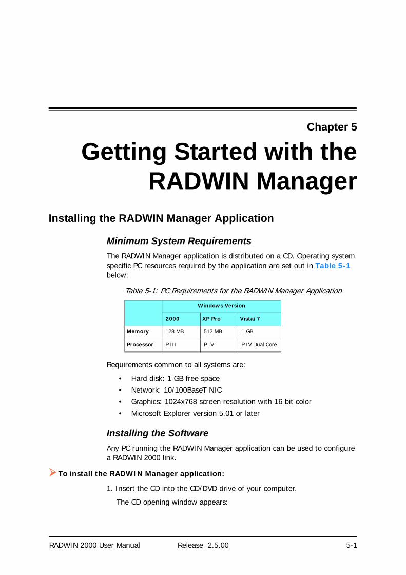
RADWIN 2000 User Manual Release 2.5.00 5-1
Chapter 5
Getting Started with theRADWIN Manager
Installing the RADWIN Manager Application
Minimum System RequirementsThe RADWIN Manager application is distributed on a CD. Operating system specific PC resources required by the application are set out in Table 5-1 below:
Requirements common to all systems are:
• Hard disk: 1 GB free space• Network: 10/100BaseT NIC• Graphics: 1024x768 screen resolution with 16 bit color
• Microsoft Explorer version 5.01 or later
Installing the SoftwareAny PC running the RADWIN Manager application can be used to configure a RADWIN 2000 link.
To install the RADWIN Manager application:
1. Insert the CD into the CD/DVD drive of your computer.
The CD opening window appears:
Table 5-1: PC Requirements for the RADWIN Manager Application
Windows Version
2000 XP Pro Vista/7
Memory 128 MB 512 MB 1 GB
Processor P III P IV P IV Dual Core

Getting Started with the RADWIN Manager Chapter 5
RADWIN 2000 User Manual Release 2.5.00 5-2
2. Choose Install RADWIN Manager and follow the on-screen instructions of the installation wizard to complete the setup of the RADWIN Manager application.
If the installation program fails to start, browse to your CD/DVD drive, chose the setup.exe program and run it.
Getting Started with the RADWIN Manager If your links are within easy reach, you can configure them using the proce-dure described below. If however, your links are to be geographically scat-tered, it may be convenient to pre-load each ODU with its network address prior to physical installation. The procedure is quite straight forward, and set out in Chapter 19.
To start the RADWIN Manager:
1. Connect the managing computer to one of the two LAN ports as shown in Figure 5-1 below:
Note
Each ODU requires a static IP address, since part of the link definition is the IP address pair of both ODUs. Network Managers should ensure that these addresses are outside of the automatic allocation ranges used by their network DHCP server.
?
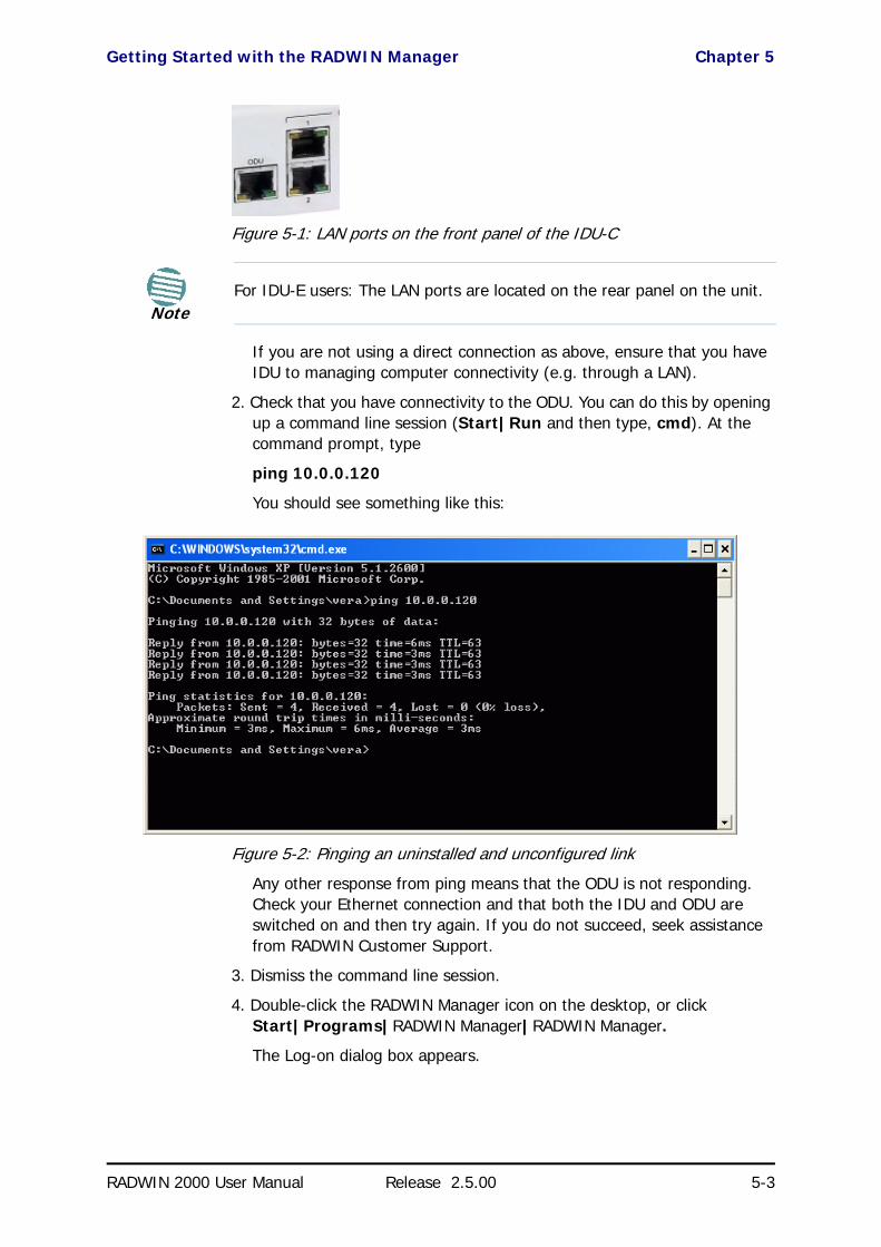
Getting Started with the RADWIN Manager Chapter 5
RADWIN 2000 User Manual Release 2.5.00 5-3
Figure 5-1: LAN ports on the front panel of the IDU-C
If you are not using a direct connection as above, ensure that you have IDU to managing computer connectivity (e.g. through a LAN).
2. Check that you have connectivity to the ODU. You can do this by opening up a command line session (Start|Run and then type, cmd). At the command prompt, type
ping 10.0.0.120
You should see something like this:
Figure 5-2: Pinging an uninstalled and unconfigured link
Any other response from ping means that the ODU is not responding. Check your Ethernet connection and that both the IDU and ODU are switched on and then try again. If you do not succeed, seek assistance from RADWIN Customer Support.
3. Dismiss the command line session.
4. Double-click the RADWIN Manager icon on the desktop, or click Start|Programs|RADWIN Manager|RADWIN Manager.
The Log-on dialog box appears.
NoteFor IDU-E users: The LAN ports are located on the rear panel on the unit.

The RADWIN Manager log-on Concept Chapter 5
RADWIN 2000 User Manual Release 2.5.00 5-4
Figure 5-3: First time log-on window
The RADWIN Manager log-on ConceptThe RADWIN Manager provides three levels of access in one of two entry modes. To see them, click Options at any time in the Log on window (Figure 5-3 above). You are offered an extended log-on window:
Figure 5-4: Extended log-on window
At the User Type field, click the list button:
Note
Connection through the RMNS Sever will be available in a future release. If you have an immediate requirement for this service, please contact RADWIN Customer Support.

The RADWIN Manager log-on Concept Chapter 5
RADWIN 2000 User Manual Release 2.5.00 5-5
Figure 5-5: Log on window exposing the user types.
There are three user types:
• An Observer has read-only access to the link. An Observer can monitor the link, generate reports, but may not change any link parameters.
• An Operator can install and configure the link.• An Installer can, in addition to functioning as an Operator, also
change the operating band. The latter function has legal ramifica-tions, requiring familiarity with local regulations.
The following table summarizes these options:
The Network Manager should change the default passwords as soon as pos-sible.
Continuing the log-on procedure:
5. Type an IP address for the ODU (if you connect through a LAN), or click Local Connection (if you are connected directly to the IDU port).
Table 5-2: User types, default passwords and function
User Type Default Password Function Community Community
String
Observer admin Monitoring Read-Only public
Operator admin Installation, configuration
Read-Write netman
Installer wireless Operator plus set band
Read-Write netman

Log-on Errors and Cautions Chapter 5
RADWIN 2000 User Manual Release 2.5.00 5-6
6. If your User Type is not Operator, then choose it now.
7. Enter the password.
8. If you are a user with Read-Write permission, click Options to enter the Community options if required
9. For initial log on:
• Leave the default Community passwords, netman for read-write, and public for read-only.
• If Community values were previously defined, enter them under Community in the Read-Only or Read-Write boxes.
• If you are a user with read-only permission, then you may only log on as Observer.
The RADWIN Manager main window is displayed (see Figure 5-10).
Log-on Errors and Cautions
Unsupported DeviceAttempting to connect to an unsupported device on an otherwise valid IP address (for example, a LAN printer) will result in the following error mes-sage:
Warning
• If you log on using Local Connection, but your physical connection is not local (i.e. anything other than a direct connection between the managing computer and the IDU), then any configuration you carry out may affect other links in the network. Do not do this!
• Network log on (IP address to the ODU) is recommended.• If you log on via an over-the-air IP address, you will receive a warn-
ing. If you reset the site to which you are connected to factory set-tings, you can lock yourself out of the link.
Note
• If you log on using Local Connection through a PoE device, you will need to connect it to the managing computer using a crossed Ether-net cable.
• The default IP address for the ODU is 10.0.0.120. The subnet mask is 255.0.0.0.
• The actual IP address is defined during link configuration (see Site Management: IP Address, VLAN and Protocol on page 8-7. See also, Chapter 19).
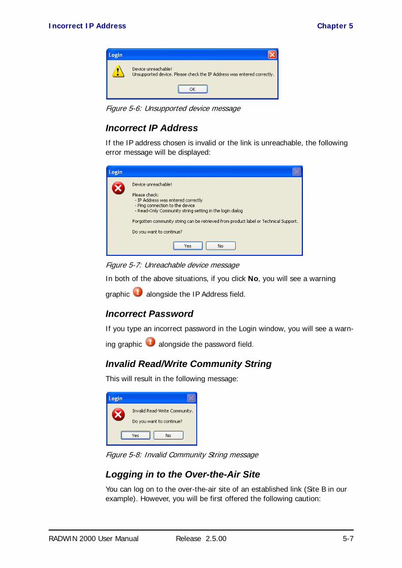
Incorrect IP Address Chapter 5
RADWIN 2000 User Manual Release 2.5.00 5-7
Figure 5-6: Unsupported device message
Incorrect IP AddressIf the IP address chosen is invalid or the link is unreachable, the following error message will be displayed:
Figure 5-7: Unreachable device message
In both of the above situations, if you click No, you will see a warning
graphic alongside the IP Address field.
Incorrect PasswordIf you type an incorrect password in the Login window, you will see a warn-
ing graphic alongside the password field.
Invalid Read/Write Community StringThis will result in the following message:
Figure 5-8: Invalid Community String message
Logging in to the Over-the-Air SiteYou can log on to the over-the-air site of an established link (Site B in our example). However, you will be first offered the following caution:

Continuing without an IP Address Chapter 5
RADWIN 2000 User Manual Release 2.5.00 5-8
Figure 5-9: Logging on to an over-the-air site
Continuing without an IP AddressThe RADWIN Manager provides limited “offline” functionality when there is no accessible IDU/ODU. It is primarily for setting managing computer related parameters, running the Link Budget Calculator or viewing online Help. The offline functionality is shown in Table 5-3 below. The table does not show menu items grayed out.
Changing the Log-On Password
To change the log on password:
1. From the Tools menu, select Change Password.
The Change Password dialog box appears.
Table 5-3: RADWIN Manager: Offline Functionality
Menu levelFunction Reference
Top +1 +2
File
Log Off Return to log-on dialog. Same as Log Off button
Exit Exit the RADWIN Manager. Same as Exit button
Tools
Change Password Change the log-on password page 5-8
Events LogClear Events Clear local events log
page 9-17Save to File Save events log data to a file
Preferences Set managing computer preferences
Help
RADWIN Manager Help View online help version of the User Manual
Link Budget Calculator Calculator opened in default browser Chapter 21
Get Diagnostics Information Obtain system information page 9-1
About RADWIN Manager RADWIN Manager build information

First steps Chapter 5
RADWIN 2000 User Manual Release 2.5.00 5-9
2. Enter the current password, and the new password.
3. Click OK to confirm.
First steps
At this point the main window of the RADWIN Manager should be displayed:
Figure 5-10: Opening RADWIN Manager window prior to installation - IDU-C
Note
A valid log-on password must contain at least five characters excluding SPACE, TAB, and any of “>#@|*?;.”
Note
For what follows, it is assumed that you have set the IP addresses of both ODUs. For the purposes of illustration, we will use the following IP addresses:
Our managing computer has its NIC set to IP address 192.168.1.100. The log-on ODU is set to IP address 192.168.1.101 and the over-the-air ODU is set to 192.168.1.102. The Subnet Mask for both sites is 255.255.255.0 and the Default Gateway is left unset. We will maintain this arrangement throughout the remainder of this manual.
Other defaults are shown in Table 5-4.

First steps Chapter 5
RADWIN 2000 User Manual Release 2.5.00 5-10
A detailed field by field description of the contents of the RADWIN Manager main window may be found in Chapter 6.
The procedure required to make the link functional has three phases:
1. Link Installation - which we will detail below.
Installation actually gets the link operational by setting the link parame-ters. It uses a fixed channel at the lowest possible modulation, BPSK at 6.5Mbps and will work under the harsh interference condition.
2. Link Configuration - described in Chapter 7.
Configuration provides much the same functionality as Installation, but for a running link. A fallback to Installation mode is provided for situa-tions which cannot be handled without resetting the link, such as antenna realignment and IDU or ODU replacement.
The Link Installation and Configuration phases are both carried out with Wizards, which “walk you through” the processes. The Wizards are visu-ally quite similar and will be described in detail below.
3. Site Configuration - described in Chapter 8.
Site specific configuration for each side of the link is available at any time - under a running link or under the restricted Installation mode.
Site Configuration consists of a set of panels, which may be invoked indi-vidually in any order, as needed.
NoteThe Dynamic Tx Ratio bar only appears for model RADWIN 2000 C
Note
During the installation procedure, the definition of all parameters is automatically applied to both sides of the link.
Caution
• The ODUs as supplied by RADWIN are set up with a factory default band. If for some reason the default band needs to be changed, it should be done before link Installation. The procedure is set out in Chapter 20.
• Use of an incorrect band may be in violation of local regulations.
Note
An installed and configured link can be returned to installation mode for re-installation and configuration from last settings or from factory settings.
• Reversion to installation mode requires a complete break in the link service
• Configuration mode may vary the service throughput and quality, but without a service break

Default RADWIN 2000 Settings Chapter 5
RADWIN 2000 User Manual Release 2.5.00 5-11
Default RADWIN 2000 SettingsThe default settings of the RADWIN 2000 configuration parameters are listed in the second column of Table 5-4 below. The third column shows the values we use in this manual for illustrative purposes.
Using RADWIN Manager Spectrum ViewPrior to running the Installation Wizard (Chapter 5), you may use the RAD-WIN Manager Spectrum View utility.
The RADWIN Manager Spectrum View utility is an RF survey tool designed to support the link installation prior to full link service activation. The tool provides comprehensive and clear information enabling easier, faster and better quality installations.
Table 5-4: Default Settings
Parameter Default Value Illustrative Value
Factory default band Product dependent 5.820GHz
ODU IP Address 10.0.0.120 192.168.1.101 and 102
Subnet Mask 255.0.0.0 255.255.255.0
Trap destination 0.0.0.0 0.0.0.0
RADWIN Manager log-on passwords
Observer admin
Operator admin
Installer wireless
Link ID Link EBG_20561334
Link Name Name TPSF_BTT
Site 1 Site A
Site 2 Site B
Location (per site) Location A B
Name (per site) Name Here There
Contact (per site) Person John Mary
Link Password wireless-bridge
Rate Adaptive
Ethernet Configuration Auto Detect
Radio Link Failure Actions No action
Bridge or Hub mode Hub Mode, Aging time = 300 sec
Community valuesRead-write – netman
Read-only – public

Using RADWIN Manager Spectrum View Chapter 5
RADWIN 2000 User Manual Release 2.5.00 5-12
To launch Spectrum View, go to the main window menu (Figure 5-11) and click Tools | Spectrum View. A display similar to the following appears:
Figure 5-11: Spectrum View - Opening Display on installed link
See Chapter 22 for detailed information about operating Spectrum View and understanding the displayed statistics.

RADWIN 2000 User Manual Release 2.5.00 6-1
Chapter 6
The RADWIN Manager:Main Window
One Manager for all RADWIN Radio ProductsThe RADWIN Manager application is largely generic to all RADWIN Radio Products.
Functionality differences are minimal according to radio series (WinLink 1000 and RADWIN 2000) capabilities.
The Main Window of the RADWIN ManagerEnsure that the RADWIN Manager is running.
The main window should look similar to that in Figure 6-1:

The RADWIN Manager Toolbar Chapter 6
RADWIN 2000 User Manual Release 2.5.00 6-2
Figure 6-1: Main window, Wireless Link is Active
The main window of the RADWIN Manager contains a large amount of information about the link. Before proceeding to details of link configuration we set out the meaning of each item in the main window.
The RADWIN Manager ToolbarIn configuration mode, the RADWIN Manager toolbar contains the following buttons:
In Installation mode, Link Configuration is grayed out and Link Installation is open.
The button functions are set out in Table 6-1:
Table 6-1: RADWIN Manager Toolbar
Item Description
Link ConfigurationChanges configuration parameters of an operating wireless link; assigns text files for storing alarms, statistics and configuration data. This button is disabled until a link installation has been completed
Link Installation Performs preliminary configuration of the system. This button is disabled after the link is installed

Main Menu Functionality Chapter 6
RADWIN 2000 User Manual Release 2.5.00 6-3
Main Menu FunctionalityThe main menu contains the following items:
The RADWIN Manager menu functionality is displayed in Table 6-2.
Site: <Site 1 name> Opens the Site configuration dialog for Site 1. Same as Configuration | 1 Configure <Site 1 name>
Site: <Site 2 name> Opens the Site configuration dialog for Site 2. Same as Configuration | 2 Configure <Site 2 name>
Get Diagnostics Obtain system information
Clear Counters Clears TDM error blocks counters. Disabled for Ethernet-only link
Log off Closes the current session and logs off RADWIN Manager
Exit Exits RADWIN Manager
Help Opens Help on the use of contextual online help
Table 6-2: RADWIN Manager main menu functionality
Menu levelFunction Reference
Top +1 +2
File
Log Off Return to log-on dialog. Same as Log Off button
Exit Exit the RADWIN Manager. Same as Exit button
Configuration
Link Configuration Run the Configuration Wizard. Not available in Installation Mode
Chapter 7
1 Configure <Site 1 name>
Opens the Site configuration dialog for Site 1. Has a path to return to Installation Mode
Chapter 8
2 Configure <Site 2 name>
Opens the Site configuration dialog for Site 2. Has a path to return to Installation Mode
Link Installation Runs the Installation Wizard. Not available in Configuration Mode
Chapter 5
Table 6-1: RADWIN Manager Toolbar (Continued)
Item Description
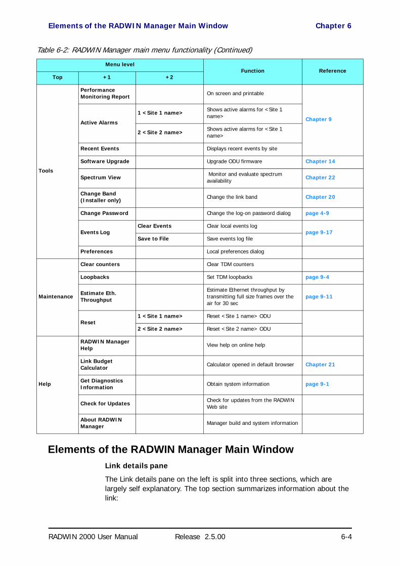
Elements of the RADWIN Manager Main Window Chapter 6
RADWIN 2000 User Manual Release 2.5.00 6-4
Elements of the RADWIN Manager Main WindowLink details pane
The Link details pane on the left is split into three sections, which are largely self explanatory. The top section summarizes information about the link:
Tools
Performance Monitoring Report On screen and printable
Chapter 9Active Alarms
1 <Site 1 name> Shows active alarms for <Site 1 name>
2 <Site 2 name> Shows active alarms for <Site 1 name>
Recent Events Displays recent events by site
Software Upgrade Upgrade ODU firmware Chapter 14
Spectrum View Monitor and evaluate spectrum availability
Chapter 22
Change Band (Installer only) Change the link band Chapter 20
Change Password Change the log-on password dialog page 4-9
Events LogClear Events Clear local events log
page 9-17Save to File Save events log file
Preferences Local preferences dialog
Maintenance
Clear counters Clear TDM counters
Loopbacks Set TDM loopbacks page 9-4
Estimate Eth. Throughput
Estimate Ethernet throughput by transmitting full size frames over the air for 30 sec
page 9-11
Reset1 <Site 1 name> Reset <Site 1 name> ODU
2 <Site 2 name> Reset <Site 2 name> ODU
Help
RADWIN Manager Help View help on online help
Link Budget Calculator Calculator opened in default browser Chapter 21
Get Diagnostics Information Obtain system information page 9-1
Check for Updates Check for updates from the RADWIN Web site
About RADWIN Manager Manager build and system information
Table 6-2: RADWIN Manager main menu functionality (Continued)
Menu levelFunction Reference
Top +1 +2

Elements of the RADWIN Manager Main Window Chapter 6
RADWIN 2000 User Manual Release 2.5.00 6-5
For Link status possibilities and color codes, see Table 9-2.
The two lower left panels show basic link site details:
The three fields for each site are user definable. see page 8-7ff.
The Monitor pane
The monitor pane, is the main source of real time information about link performance at both link sites. It includes the following panes (top to bot-tom):
• Radio Interface, Received Signal Strength (RSS) in dBm and Trans-mission Ratio:
• Ethernet Service:
NoteThe Dynamic Tx Ratio bar only appears for model RADWIN 2000 C

Elements of the RADWIN Manager Main Window Chapter 6
RADWIN 2000 User Manual Release 2.5.00 6-6
• Estimated Ethernet Throughput: The numbers are the current calculated throughputs at each site. The colored bars (with numbers) indicate the maximum possible throughput having regard for air conditions.
• Rx and Tx Rates: The Rx and Tx rates are the receive and transmit rates on the LAN side of each ODU, not the air side. For a balanced link, the Rx and Tx rates at the LAN side of Site A will match the Tx and Rx rates at the LAN side of Site B respectively. In all cases, The LAN side Rx rate shown will be the same as the air side Tx rate for each individual ODU.Actual Ethernet traffic received and transmitted rates per site, is in Mbps of Fps, selectable in the panel title bar.
• TDM Services: IDU-C and new style IDU-E:
• The title bar enables you to switch between Accumulative and Current view.
• Immediately below the title bar is displayed the TDM Block Fail-ure Ratio. It is zeroed by the Clear Counters button in the tool bar.
• Error block count is shown immediately above the active TDM channels display.
• The color of the TDM ports reflects their current status:• Green - Operational• Red - Error: LOS for loss of signal and AIS for Alarm Indi-
cation Signal• Yellow - Loopback• Gray - Inactive
• Frequency box: It shows the link frequency. The color of the box indicates the status
• Green is an active link• Red is an inactive link

Elements of the RADWIN Manager Main Window Chapter 6
RADWIN 2000 User Manual Release 2.5.00 6-7
• Magenta indicates an authentication or compatibility problem• Brown indicates severe compatibility problem
Events Log
The Events Log, stores alarms generated from both sides of the link and is detailed in Chapter 9.
Status Bar
The Status bar, displays the following icons:
Table 6-3: Status bar indicators
Icon or Label Purpose
Connectivity Shows if RADWIN Manager is communicating with the ODU.
Connection available
Connection mode to the ODU• Over-the-Air connection - using the IP address of the remote unit.• Local connection - direct connection to the IDU without using an IP
address.• Network connection - through a LAN
ODU unreachable
IP Address Log on IP address
Encryption indicator
Normally encrypted link
Unencrypted link - lock open
Link password validation failed. The link is encrypted with default keys.
Service and configuration are unavailable. Change the link password.
Link Lock
Link Lock enabled
Link Lock encrypted
Link Lock mismatch
Ethernet Ring Member
DFS in use
Rescue Alarm In the event of an active alarm, opens alarms dialog

Elements of the RADWIN Manager Main Window Chapter 6
RADWIN 2000 User Manual Release 2.5.00 6-8
RADWIN RNMS users will see an additional field showing the IP address of the RNMS server:

RADWIN 2000 User Manual Release 2.5.00 7-1
Chapter 7
Configuring the LinkOverview
This chapter describes the link configuration procedure, which is performed after the installation of both sides of the RADWIN 2000 link, as set out in Chapter 5.
Link configuration uses a Link Configuration wizard to redefine the configu-ration parameters and fine-tune an operational link. Both sides of the link are configured simultaneously.
Link configuration allows you to configure link parameters, which do not lead to sync loss or require a reset. Some may change service performance, in respect of which, warnings are displayed.
For ease of use, the Link Configuration wizard follows the same pattern as Link Installation. You should therefore be familiar with the content of Chap-ter 5.
The following parameters are configured using the Link Configuration Wiz-ard:
• System parameters• Channel settings• Transmission power and antenna settings
• Service parameters
The Configuration Wizard has seven steps as shown in Table 7-1 below.
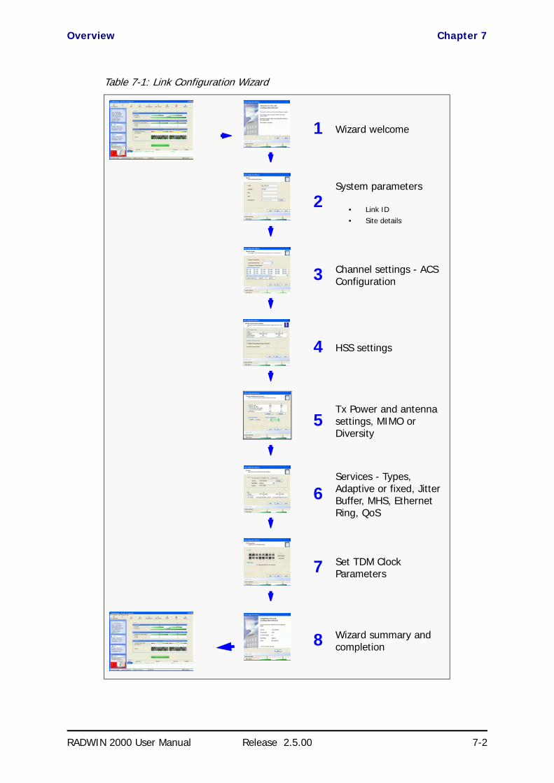
Overview Chapter 7
RADWIN 2000 User Manual Release 2.5.00 7-2
Table 7-1: Link Configuration Wizard
1 Wizard welcome
2System parameters
• Link ID• Site details
3 Channel settings - ACS Configuration
4 HSS settings
5Tx Power and antenna settings, MIMO or Diversity
6Services - Types, Adaptive or fixed, Jitter Buffer, MHS, Ethernet Ring, QoS
7 Set TDM Clock Parameters
8 Wizard summary and completion
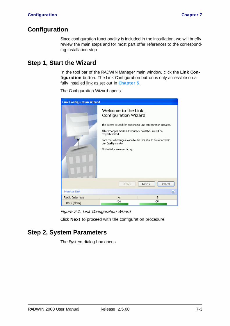
Configuration Chapter 7
RADWIN 2000 User Manual Release 2.5.00 7-3
ConfigurationSince configuration functionality is included in the installation, we will briefly review the main steps and for most part offer references to the correspond-ing installation step.
Step 1, Start the WizardIn the tool bar of the RADWIN Manager main window, click the Link Con-figuration button. The Link Configuration button is only accessible on a fully installed link as set out in Chapter 5.
The Configuration Wizard opens:
Figure 7-1: Link Configuration Wizard
Click Next to proceed with the configuration procedure.
Step 2, System ParametersThe System dialog box opens:
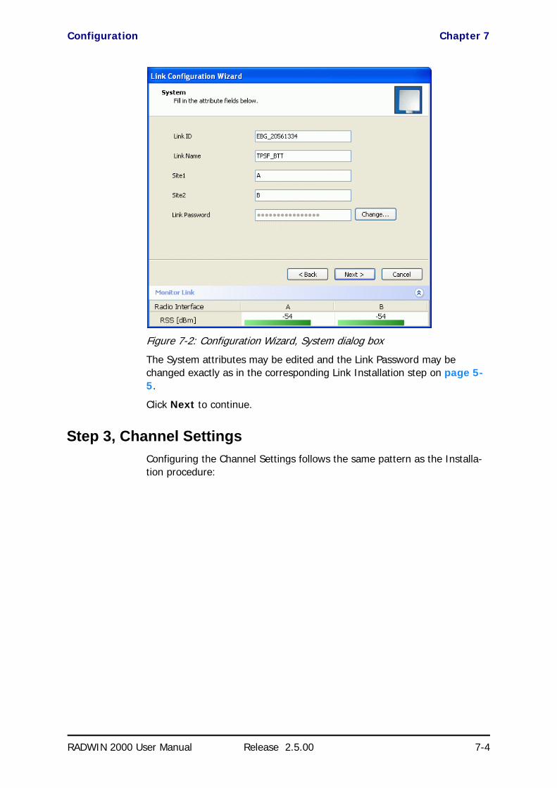
Configuration Chapter 7
RADWIN 2000 User Manual Release 2.5.00 7-4
Figure 7-2: Configuration Wizard, System dialog box
The System attributes may be edited and the Link Password may be changed exactly as in the corresponding Link Installation step on page 5-5.
Click Next to continue.
Step 3, Channel SettingsConfiguring the Channel Settings follows the same pattern as the Installa-tion procedure:

Configuration Chapter 7
RADWIN 2000 User Manual Release 2.5.00 7-5
Figure 7-3: Channel Settings dialog box - Automatic Channel Selection
Notice that the operating channel is grayed out. If you use the Reselect Channel button, to change it, you will be asked for confirmation:
If you accept, then the system will search for the best operating channel:

Configuration Chapter 7
RADWIN 2000 User Manual Release 2.5.00 7-6
Figure 7-4: Searching for the best operating channel
The link will return to the status of Figure 7-3 above with a possible change to the operating channel.
If you work without automatic channel selection, the Channel Settings win-dow looks like this:
Figure 7-5: Channel Settings without automatic channel selection

Configuration Chapter 7
RADWIN 2000 User Manual Release 2.5.00 7-7
If you click the Operating Channel drop-down list, the following window appears:
Figure 7-6: Channel frequency options
Selecting one of the frequencies presented returns you to the status of Figure 7-5 with the appropriate change. If you choose Other..., the fol-lowing window opens:
Figure 7-7: Choosing an “Other” Operating Channel frequency

Configuration Chapter 7
RADWIN 2000 User Manual Release 2.5.00 7-8
The right hand drop-down list (showing the current Operating Channel) allows you to fine-tune the frequency in increments of ±5MHz within a range of the operating band, which in this example is 5.740 - 5.835 GHz.
The Channel Bandwidth may also be changed. The available choices are 10, 20 and 40MHz depending on regulation (see Appendix A).
When you have completed making your choice, click Next to continue.
Step 4, Tx Power and Antenna SettingsThe Tx Power and Antenna Settings window is similar to that for Installa-tion:
Figure 7-8: Transmission Power and Antenna Parameters
As in Installation mode, you need to consider three items:
• Number of antennas at each Link site (1 or 2)• Tx Power setting for each one• MIMO or Diversity mode
Changing Number of Antennas and Tx PowerTX Power, Antenna Gain and Cable LossIf you chose to configure either antenna, you are presented with the follow-ing window:

Configuration Chapter 7
RADWIN 2000 User Manual Release 2.5.00 7-9
Figure 7-9: Antenna configuration dialog with opened type selection
(Recall that we are using an unrealistically low Tx power here because our link in a laboratory.)
So far, the procedure duplicates the corresponding Installation process. If you choose a different antenna type and click OK, you will receive the fol-lowing cautionary message:
You may also change the Required Tx Power, Antenna Gain and Cable Loss. The procedure is the same as that set out in the Installation procedure on page 5-13.
Switching Between Single and Dual AntennasSingle/Dual Antenna mode selection works precisely the same way as shown on page 5-20. If you use this option you will receive a warning sim-ilar to this:
Caution
In this context, entering Installation mode causes a service break until it is restored by running the Installation wizard.
If you are uncertain, do not do this without expert technical assistance.

Configuration Chapter 7
RADWIN 2000 User Manual Release 2.5.00 7-10
Switching Between MIMO and Diversity ModesA similarly worded warning applies to a s switch from Diversity to MIMO mode. The considerations are otherwise no different from those set out in the corresponding Installation step.
When you have completed making your choice, proceed to the Services window.
Step 5, Hub Site Synchronization Settings
Figure 7-10: HSS Settings
The Synchronization Status dialog box displays the current status of each side of the link. See Chapter 10 for instructions about installing and con-figuring collocated links. If you do not require HSS, click Next.
Step 6, ServicesHere is the services dialog:
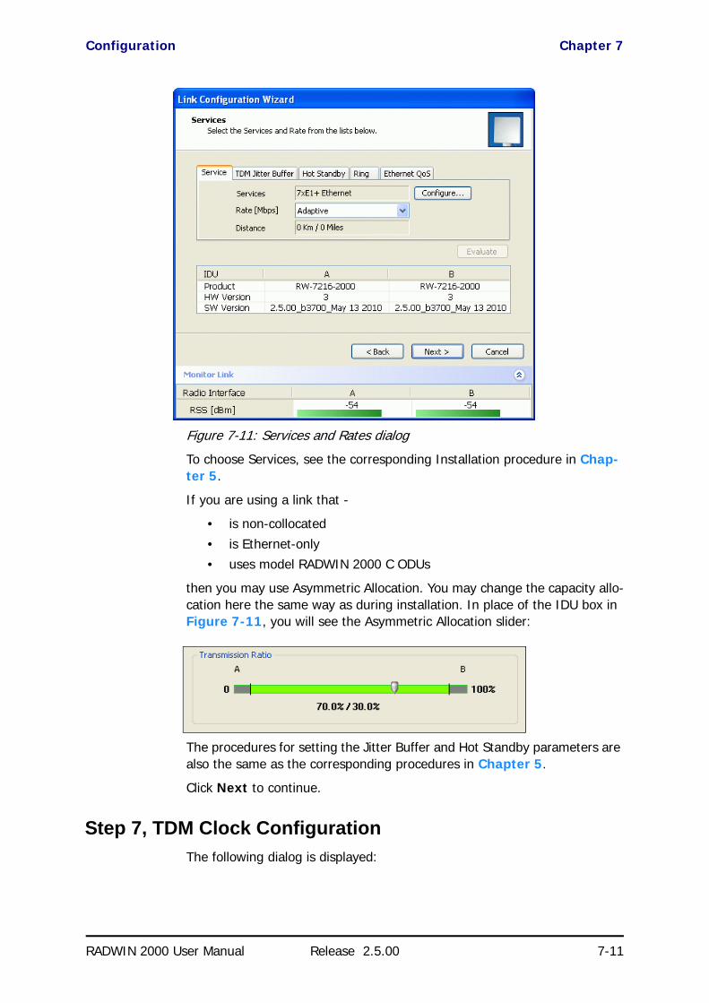
Configuration Chapter 7
RADWIN 2000 User Manual Release 2.5.00 7-11
Figure 7-11: Services and Rates dialog
To choose Services, see the corresponding Installation procedure in Chap-ter 5.
If you are using a link that -
• is non-collocated
• is Ethernet-only• uses model RADWIN 2000 C ODUs
then you may use Asymmetric Allocation. You may change the capacity allo-cation here the same way as during installation. In place of the IDU box in Figure 7-11, you will see the Asymmetric Allocation slider:
The procedures for setting the Jitter Buffer and Hot Standby parameters are also the same as the corresponding procedures in Chapter 5.
Click Next to continue.
Step 7, TDM Clock ConfigurationThe following dialog is displayed:
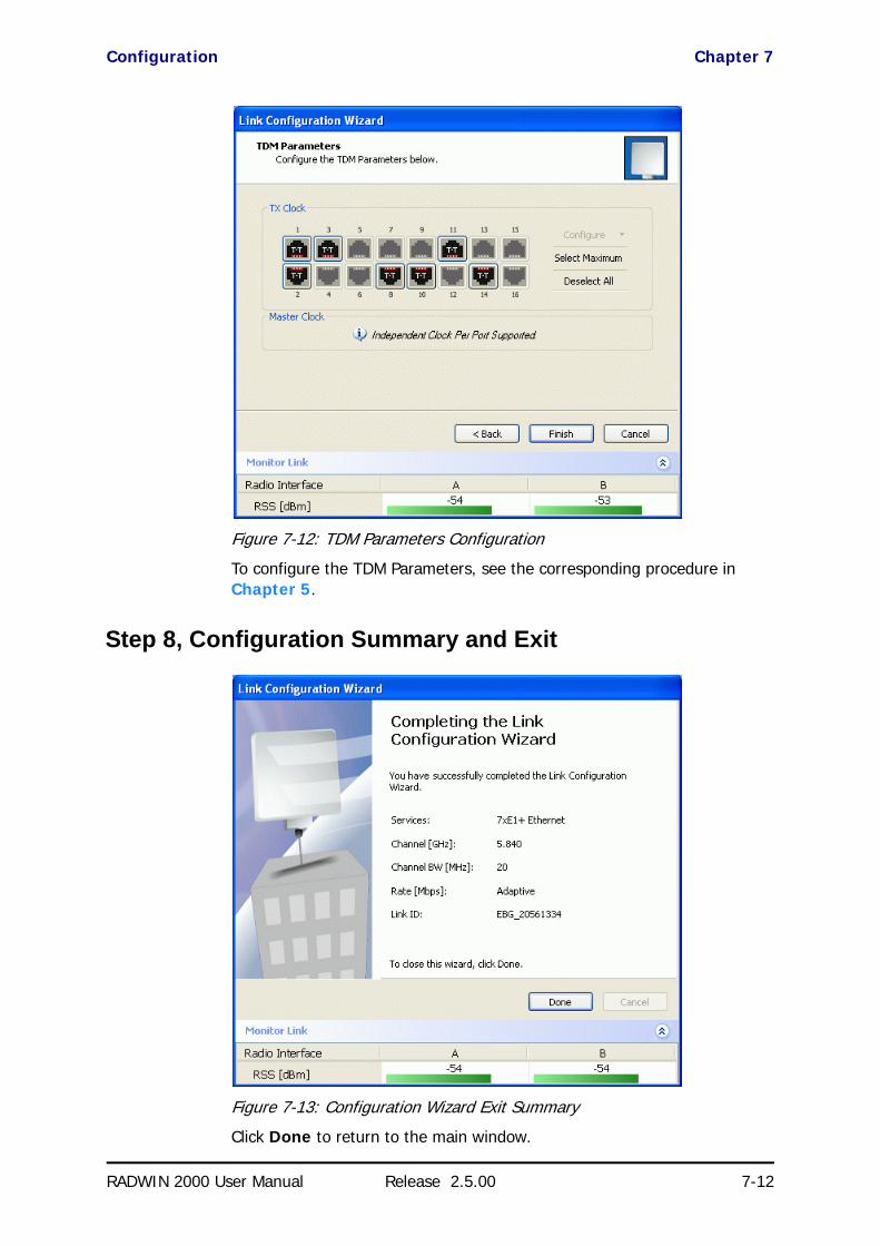
Configuration Chapter 7
RADWIN 2000 User Manual Release 2.5.00 7-12
.
Figure 7-12: TDM Parameters Configuration
To configure the TDM Parameters, see the corresponding procedure in Chapter 5.
Step 8, Configuration Summary and Exit
Figure 7-13: Configuration Wizard Exit Summary
Click Done to return to the main window.
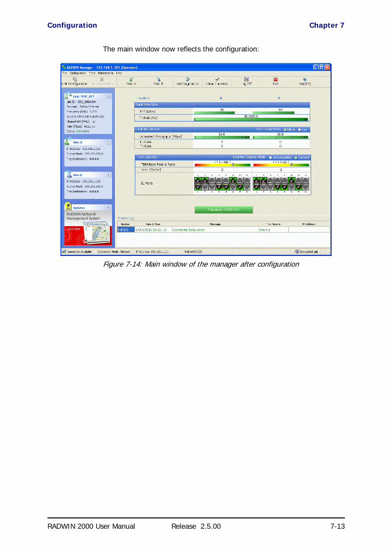
Configuration Chapter 7
RADWIN 2000 User Manual Release 2.5.00 7-13
The main window now reflects the configuration:
Figure 7-14: Main window of the manager after configuration

RADWIN 2000 User Manual Release 2.5.00 8-1
Chapter 8
Site ConfigurationThe Site Configuration dialog panels are used to configure parameters, which may differ between both sides of the link.
The parameters configured using the Site Configuration dialog panels include (among others):
• System settings• Air interface - Transmit (Tx) power and antenna
• Hub Site Synchronization status• Network management including VLAN• Inventory - link hardware and software model details
• Security settings• Date and time• Ethernet service settings
• TDM Hot Standby status• External alarms settings• Operations - Revert to factory settings
The Operations dialog offers a “doorway” to jump into installation mode.
The Site Configuration dialog has its own main menu with the following extra functionality:
• Backup ODU software• Restore ODU software or configuration from a backup file• Refresh the current panel
• Enable/disable the site ODU buzzer• Jump back into installation mode keeping current configuration set-
tings
Configuring the Site
Editing the Configuration Parameters by SiteYou can edit the configuration parameters for each site individually. The fol-lowing functions are available from the left side of the dialog box.

Editing the Configuration Parameters by Site Chapter 8
RADWIN 2000 User Manual Release 2.5.00 8-2
Figure 8-1: Configuration Dialog Box
Functions on the left of the dialog box:
Functions at the top of the dialog box:
System Edit the contact person and location details. View the system details
Air Interface Change the Tx Power, cable loss, antenna type and settings.
View HSS settings
Management Configure the IP address, Subnet Mask, Default Gateway, Trap Destination and VLAN
Inventory View the hardware and software inventory (product identification, versions, MAC address and serial number)
Security Change the Community Values and the Link Password. Set Link Lock.
Date and Time Set the date and time of the link from an NTP servers or from the managing computer
Advanced Choose Hub or Bridge ODU mode, IDU aging time, set the Ethernet ports configuration, set max. information rate, TDM MHS status, set the external alarm inputs, restore factory settings, set IDU detection mode.
Backup Save the current ODU software to a file
Restore Restore an ODU’s software or configuration from a backup file created by the backup facility
Refresh Refresh current panel with latest values
Installation Mode Return to Installation Mode for the entire link.
Selecting the Mute check box before clicking the Install Mode button mutes the Beeper.

Viewing System Details Chapter 8
RADWIN 2000 User Manual Release 2.5.00 8-3
To edit the Configuration Parameters:
1. Click the required site button on the main tool bar of the RADWIN Man-ager
OR
Click Configuration from the main menu and choose a site to config-ure.
The Configuration dialog box opens (see Figure 8-1 above).
2. Choose the appropriate item in the left hand list to open a dialog box.
3. Click Apply to save changes.
In subsequent instructions, we will simply say “Choose a site to configure” on the understanding that the foregoing procedure is implied.
Viewing System DetailsThis is the first window displayed - as depicted above. You can edit the con-tact details and site names.
Viewing Air Interface DetailsClick the Air Interface item in the left hand list. A window similar to the fol-lowing appears:
Figure 8-2: Air interface details
Buzzer Mutes the alignment tone in installation mode. Reactivate the beeper during alignment.

Changing the Transmit Power Chapter 8
RADWIN 2000 User Manual Release 2.5.00 8-4
Changing the Transmit PowerEach site can have a different Tx Power level.
To change the Transmit Power:
1. Choose a site to configure.
The Configuration dialog box opens.
2. Choose Air Interface (see Figure 8-3).
3. Choose the required Transmit (Tx) Power Level.
4. Click Apply to save the changes.
Figure 8-3: Changing the Transmit Power
For detailed explanation about the relationship between these parameters, see page 5-13 to 5-21.
Hub Site SyncHere you can view the HSS status:
Caution
Changing the Tx Power will affect service quality. The same considerations apply here as were noted in the Installation procedure on page 5-17.
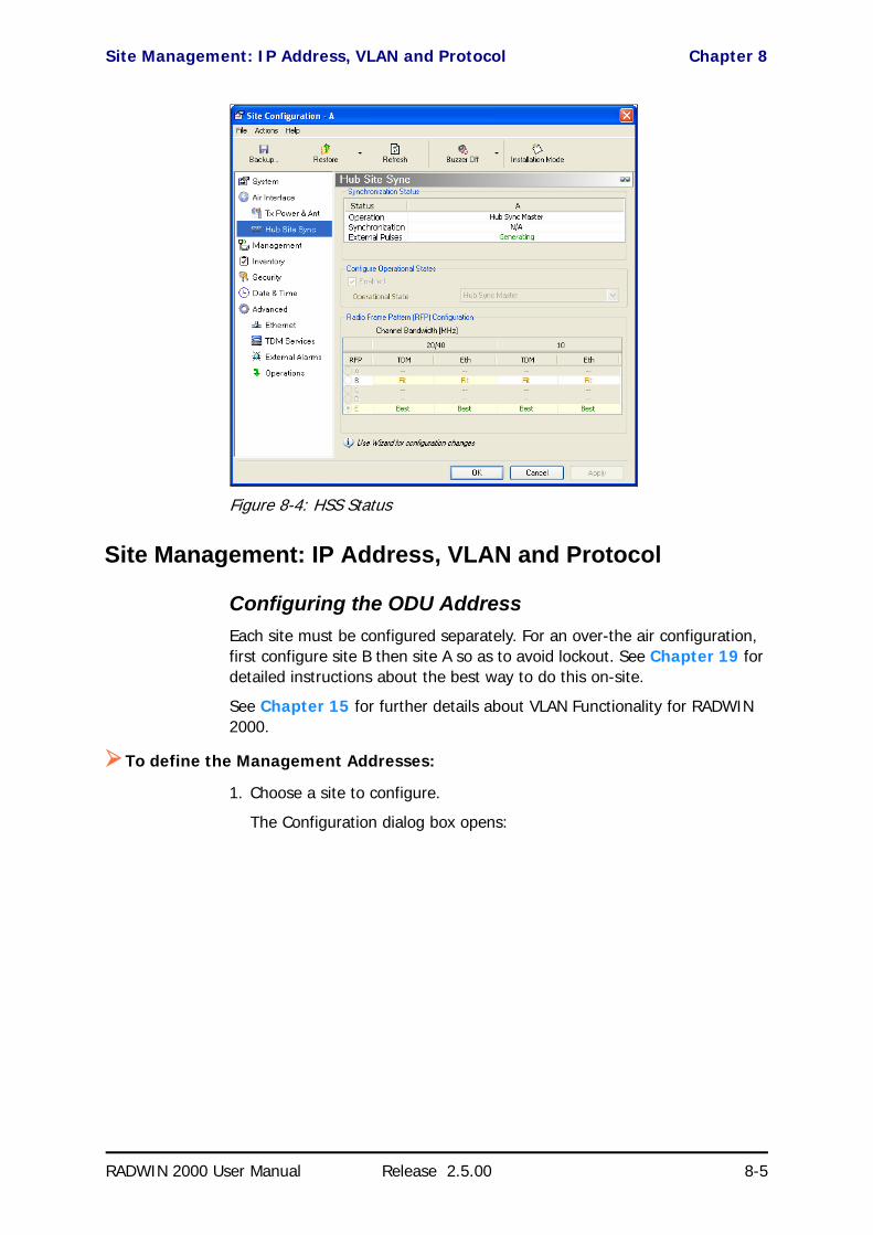
Site Management: IP Address, VLAN and Protocol Chapter 8
RADWIN 2000 User Manual Release 2.5.00 8-5
Figure 8-4: HSS Status
Site Management: IP Address, VLAN and Protocol
Configuring the ODU AddressEach site must be configured separately. For an over-the air configuration, first configure site B then site A so as to avoid lockout. See Chapter 19 for detailed instructions about the best way to do this on-site.
See Chapter 15 for further details about VLAN Functionality for RADWIN 2000.
To define the Management Addresses:
1. Choose a site to configure.
The Configuration dialog box opens:

Configuring VLAN Settings Chapter 8
RADWIN 2000 User Manual Release 2.5.00 8-6
Figure 8-5: Management Addresses - Site Configuration dialog box
5. Choose Management.
6. Enter the IP address of the ODU in the IP Address field.
7. Enter the Subnet Mask.
8. Enter the Default Gateway.
9. Enter the Trap Destination. This could be the IP address of the managing computer. The events log will be stored at this address.
10. Click Apply to save the changes.
Configuring VLAN Settings
VLAN Management enables separation of user traffic from management traffic whenever such separation is required. It is recommended that both sides of the link be configured with different VLAN IDs for management traf-fic. (This reduces your chances of accidentally locking yourself out of the link.)
To enable VLAN management:
1. Click Configuration from the main menu.
Note
If performing configuration from the RADWIN Manager, the IP address is that entered from the Login window.
Caution
VLAN IDs are used by RADWIN products in three separate contexts: Management VLAN, Traffic VLAN and Ethernet Ring. It is recommended that you use different VLAN IDs for each context.
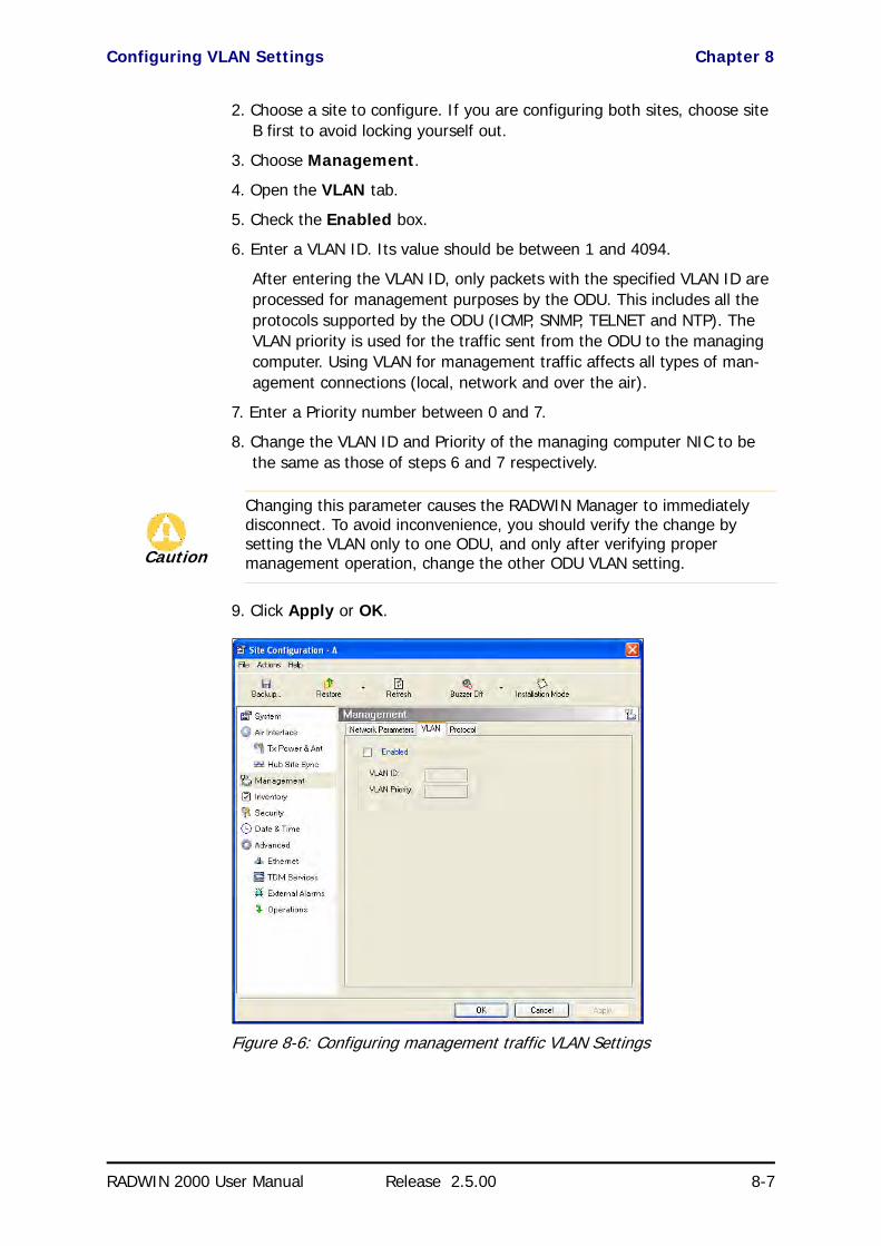
Configuring VLAN Settings Chapter 8
RADWIN 2000 User Manual Release 2.5.00 8-7
2. Choose a site to configure. If you are configuring both sites, choose site B first to avoid locking yourself out.
3. Choose Management.
4. Open the VLAN tab.
5. Check the Enabled box.
6. Enter a VLAN ID. Its value should be between 1 and 4094.
After entering the VLAN ID, only packets with the specified VLAN ID are processed for management purposes by the ODU. This includes all the protocols supported by the ODU (ICMP, SNMP, TELNET and NTP). The VLAN priority is used for the traffic sent from the ODU to the managing computer. Using VLAN for management traffic affects all types of man-agement connections (local, network and over the air).
7. Enter a Priority number between 0 and 7.
8. Change the VLAN ID and Priority of the managing computer NIC to be the same as those of steps 6 and 7 respectively.
9. Click Apply or OK.
Figure 8-6: Configuring management traffic VLAN Settings
Caution
Changing this parameter causes the RADWIN Manager to immediately disconnect. To avoid inconvenience, you should verify the change by setting the VLAN only to one ODU, and only after verifying proper management operation, change the other ODU VLAN setting.

Lost or forgotten VLAN ID Chapter 8
RADWIN 2000 User Manual Release 2.5.00 8-8
Lost or forgotten VLAN IDIf the VLAN ID is forgotten or there is no VLAN traffic connected to the ODU, then reset the relevant ODU.
During the first two minutes of connection, the ODU uses management packets both with and without VLAN. You may use this period to reconfigure the VLAN ID and priority.
Enable / Disable Telnet AccessFor a link managed in a network, direct access to an ODU using Telnet is considered to be a security breach. Telnet access may be enabled or dis-abled by clicking the Protocol tab and enabling/disabling Telnet access using the Telnet check-box:
Figure 8-7: Enable/Disable Telnet Access
Displaying the InventoryTo view the inventory data
1. Choose a site from the main menu.
The Configuration dialog box opens.
2. Choose Inventory.
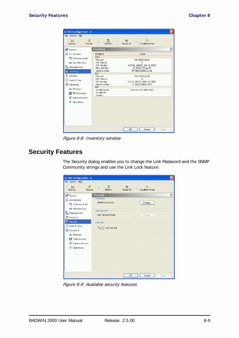
Security Features Chapter 8
RADWIN 2000 User Manual Release 2.5.00 8-9
Figure 8-8: Inventory window
Security FeaturesThe Security dialog enables you to change the Link Password and the SNMP Community strings and use the Link Lock feature:
Figure 8-9: Available security features

Changing the Link Password Chapter 8
RADWIN 2000 User Manual Release 2.5.00 8-10
Changing the Link PasswordThis item is only available when the link is down. Otherwise, it works the same way as the corresponding item on page 5-8.
RADWIN Manager Community StringsThe ODU communicates with the RADWIN Manager using SNMPv1 protocol. The protocol defines three types of communities:
• Read-Only for retrieving information from the ODU
• Read-Write to configure and control the ODU• Trap used by the ODU to issue traps.
The Community string must be entered at log on. The user must know the password and the correct Community string to gain access to the system. A user may have read-only privileges.
It is not possible to manage the ODU if the read-write or the read Commu-nity values are forgotten. A new Community value may be obtained from RADWIN Customer Support for the purpose of setting new Community. You must also have available the serial number or the MAC address of the ODU.
The read-write Community strings and read-only Community strings have a minimum of five alphanumeric characters. (bru1 and bru4097 are not per-mitted). Changing the trap Community is optional and is done by clicking the check box.
Editing Community StringsThe Community change dialog box is available from the Configuration | Security tab. Both read-write and read-only communities must be defined.
On logging on for the first time, use the following as the current Commu-nity:
• For Read-Write Community, use netman. • For Read-Only Community, use public.• For Trap Community, use public
To change a Community string:
1. From the Configuration dialog box, choose the Security tab.
2. Type the current read-write Community (default is netman).
3. Choose the communities to be changed by clicking the check box.
4. Type the new Community string and re-type to confirm. A community string must contain at least five and no more than 32 characters exclud-ing SPACE, TAB, and any of “>#@|*?;."
5. Click OK to save.

Link Lock Security Feature Chapter 8
RADWIN 2000 User Manual Release 2.5.00 8-11
Figure 8-10: Changing the Community String
Forgotten Community stringIf the read-write Community string is unknown, an alternative Community key can be used. The alternative Community key is unique per ODU and can be used only to change the Community strings. The alternative Community key is supplied with the product, and should be kept in a safe place.
If both the read-write Community and the alternative Community key are unavailable, then an alternative Community key can be obtained from RAD-WIN Customer Support using the ODU serial number or MAC address. The serial number is located on the product label. The serial number and the MAC address are displayed in the Site Configuration inventory tab.
When you have the alternative Community key, click the Forgot Commu-nity button and enter the Alternative Community key (Figure 8-11). Then change the read-write Community string.
Figure 8-11: Alternative Community Dialog box
Link Lock Security FeatureLink Lock is a part of RADWIN’s security concept intended to meet a form of abuse encountered in the field. It is designed to prevent the

Link Lock Security Feature Chapter 8
RADWIN 2000 User Manual Release 2.5.00 8-12
situation where a remote ODU can be stolen and used as a “pirate” link to steal services or information. The Link Lock feature actually locks the local ODU to be synchronized ONLY to specific remote ODU. It is a site oriented feature.
The lock can only be set from a live link. It is based on MAC authentication and is site oriented and activated on a per ODU basis. For example, if you lock the Site B ODU to the Site A ODU, you must still lock the Site A ODU to the Site B ODU to ensure complete two way locking.
Link Lock can only be removed when the link is unsynchronized. In such a case, an alarm is raised by the RADWIN Manager.
To enable Link Lock:
1. Click Site A on the main tool bar.
2. Choose the Security tab. The following window is displayed:
3. Click the Link Lock check-box and then OK. You are asked to confirm the lock:
4. Click the Yes button and you are returned to the main window of the RADWIN Manager.
Observe that a link icon is now displayed in the status bar on the bottom right of the RADWIN Manager window.

Setting the Date and Time Chapter 8
RADWIN 2000 User Manual Release 2.5.00 8-13
The link to the remote unit is now locked. If you repeat steps 1 and 2 above, the Security screen will look like this:
The Link Lock check-box is now unavailable.
5. If required, repeat the procedure for Site B.
Setting the Date and TimeThe ODU maintains a date and time. The date and time should be synchro-nized with any Network Time Protocol (NTP) version 3 compatible server.
During power-up the ODU attempts to configure the initial date and time using an NTP Server. If the server IP address is not configured or is not reachable, a default time is set.
When configuring the NTP Server IP address, you should also configure the offset from the Universal Coordinated Time (UTC). If there is no server available, you can either set the date and time, or you can set it to use the date and time from the managing computer. Note that manual setting is not
Note
To revert the Link Lock status to unlocked, power down each ODU in turn. Use the above procedure to uncheck the Link Lock status box for the live ODU.
A simple ODU reset at either end will restore the link to its previous locked or unlocked state.

Setting the Date and Time Chapter 8
RADWIN 2000 User Manual Release 2.5.00 8-14
recommended since it will be overridden by a reset, power up, or synchroni-zation with an NTP Server.
To set the date and time:
1. Determine the IP address of the NTP server to be used.
2. Test it for connectivity using the command (Windows XP), for example:
w32tm /stripchart /computer:216.218.192.202
You should get a continuous response of times, each a few seconds apart.
3. Choose a site to configure.
The Configuration dialog box opens.
4. Choose Date & Time:
Figure 8-12: Date and Time Configuration
5. If entering an IP address for the NTP Server, click Clear, and then enter the new address.
6. Set your site Offset value in minutes ahead or behind GMT1.
7. To manually set the date and time, click Change and edit the new values.
Note
The NTP uses UDP port 123. If a firewall is configured between the ODU and the NTP Server this port must be opened.
It can take up to 8 minutes for the NTP to synchronize the ODU date and time.
1. Greenwich Mean Time
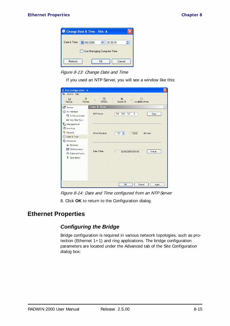
Ethernet Properties Chapter 8
RADWIN 2000 User Manual Release 2.5.00 8-15
Figure 8-13: Change Date and Time
If you used an NTP Server, you will see a window like this:
Figure 8-14: Date and Time configured from an NTP Server
8. Click OK to return to the Configuration dialog.
Ethernet Properties
Configuring the Bridge Bridge configuration is required in various network topologies, such as pro-tection (Ethernet 1+1) and ring applications. The bridge configuration parameters are located under the Advanced tab of the Site Configuration dialog box:
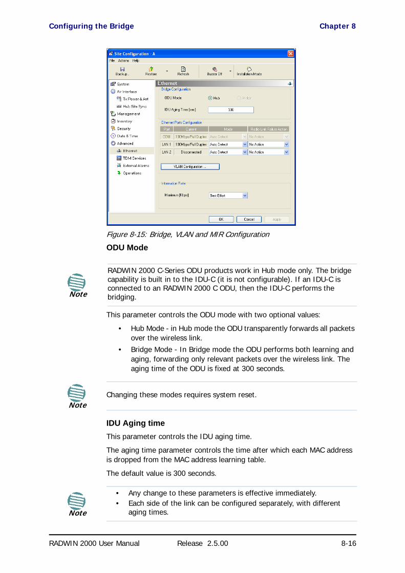
Configuring the Bridge Chapter 8
RADWIN 2000 User Manual Release 2.5.00 8-16
Figure 8-15: Bridge, VLAN and MIR Configuration
ODU Mode
This parameter controls the ODU mode with two optional values:
• Hub Mode - in Hub mode the ODU transparently forwards all packets over the wireless link.
• Bridge Mode - In Bridge mode the ODU performs both learning and aging, forwarding only relevant packets over the wireless link. The aging time of the ODU is fixed at 300 seconds.
IDU Aging timeThis parameter controls the IDU aging time.
The aging time parameter controls the time after which each MAC address is dropped from the MAC address learning table.
The default value is 300 seconds.
Note
RADWIN 2000 C-Series ODU products work in Hub mode only. The bridge capability is built in to the IDU-C (it is not configurable). If an IDU-C is connected to an RADWIN 2000 C ODU, then the IDU-C performs the bridging.
NoteChanging these modes requires system reset.
Note
• Any change to these parameters is effective immediately.• Each side of the link can be configured separately, with different
aging times.

Configuring Ethernet Ports Mode Chapter 8
RADWIN 2000 User Manual Release 2.5.00 8-17
The following table shows the appropriate configuration for several common scenarios. Both link sites must be configured with the same parameter:
Configuring Ethernet Ports ModeThe ODU Ethernet port is configured to auto-detect by default and may not be changed.
The ODU Ethernet port mode is configurable for line speed (10/100BaseT) and duplex mode (half or full duplex).
An Auto Detect feature is provided, whereby the line speed and duplex mode are detected automatically using auto-negotiation. Use manual con-figuration when attached external equipment does not support auto-negoti-ation. The default setting is Auto Detect.
To configure the Ethernet Mode:
1. From the Configuration menu, choose the site to configure.
The Site Configuration dialog box opens.
2. Click Advanced | Ethernet.
3. In the Ethernet Ports Configuration pane, use the drop-down menu to choose the configuration.
4. Click Apply to save the changes.
Table 8-1: ODU mode configuration for common scenarios
Scenario ODU Mode
IDU Aging Time
Standard (default) Configuration for Ethernet Applications Bridge 300 sec
Rapid network topology changes where fast aging is required Hub 1 sec
Caution
You should not reconfigure the port that is used for the managing computer connection, since a wrong configuration can cause a management disconnection or Ethernet services interruption.
Note
It is possible to close the Ethernet service by disconnecting the Ethernet port.
If you close the port, you may subsequently be unable to access the device. If this should occur, a workaround is as follows:
• Connect the system from the remote site• Connect via other Ethernet port (of the IDU)• Power down the equipment and connect immediately after power
up (the fastest way is to enter install mode)

VLAN Tagging for Ethernet Service: Configuration Chapter 8
RADWIN 2000 User Manual Release 2.5.00 8-18
VLAN Tagging for Ethernet Service: ConfigurationIf you are using a PoE device, this feature is unavailable. You may skip this section.
To set up VLAN tagging for Ethernet Service, click the VLAN Configuration... button in Figure 8-15. The following window is displayed:
Figure 8-16: VLAN tag settings
The choices for Ingress Mode are -
and for Egress Mode are -
Caution
VLAN IDs are used by RADWIN products in three separate contexts: Management VLAN, Traffic VLAN and Ethernet Ring. It is recommended that you use different VLAN IDs for each context.
NoteIf you are using a new style IDU-E, the SFP row will not appear.

Setting the Maximum Information Rate (MIR) Chapter 8
RADWIN 2000 User Manual Release 2.5.00 8-19
The details of setting up VLAN tagging require advanced network manage-ment skills beyond the scope of this manual. Further information for the Network Manager is provided in Chapter 15.
Setting the Maximum Information Rate (MIR)What is the MIRThe maximum Ethernet throughput of the link (MIR) can be limited. The default setting is Best Effort (see Figure 8-15 above), where the highest information rate available for the link conditions and settings is used.
What is it forThe MIR setting limits the throughput for Ethernet service. It does not affect the capacity of TDM services.
If the Link Budget Calculator or air conditions limit the capacity to X Mbps, and suppose that you use Y (< X) Mbps for TDM services, then you are left with X - Y=Z Mbps for Ethernet.
Suppose for example, that Z = 20 Mbps.
As a Service Provider, you can decide to sell a package based on 10Mbps and charge $P1 for it, or 15 Mbps for $P2 > $P1.
The MIR setting allows you do this.
The default value is “best effort” which will give Z above.
To limit the Ethernet information rate:
1. From the Configuration menu, choose the site to reconfigure.
2. Click Advanced | Ethernet
The Configuration dialog box opens.
Note
The minimum value is 256 Mbps.
The maximum value will be the minimum between Z above and -
• 10 Mbps for RADWIN 2000 PDH• 50 Mbps for RADWIN 2000 L• 100 Mbps for RADWIN 2000 C
The MIR setting is independent per direction.

Setting the Maximum Information Rate (MIR) Chapter 8
RADWIN 2000 User Manual Release 2.5.00 8-20
Figure 8-17: Bridge Configuration - Site Configuration dialog box
3. In the Information Rate pane, use the drop-down menu to choose the MIR.
Figure 8-18: Ethernet MIR - Throughput selection
4. Choose Other to define the throughput with 1 Kbps resolution
5. Choose Best Effort for the highest information rate possible for the link conditions and settings
6. Click Apply to save the changes.

TDM MHS Status Chapter 8
RADWIN 2000 User Manual Release 2.5.00 8-21
TDM MHS StatusHere you can see the TDM MHS status. There is nothing to set.
Figure 8-19: TDM MHS status
Setting External Alarm InputsThe IDU-C and the new style IDU-E have four external alarm inputs and four external alarm outputs in the form of dry-contact relays. The Alarm interface is located on the front panel of the IDU-C and is a 25-pin D-type female connector. See Appendix B, for wiring specifications and pinout. You may enable or disable each of the alarms and configure the alarm description text appearing in the alarm trap message. The ODU sends the alarm within less than a second from actual alarm trigger.
To set the external alarm inputs:
1. Choose External Alarms from the Site Configuration window.

Resetting Chapter 8
RADWIN 2000 User Manual Release 2.5.00 8-22
Figure 8-20: External Alarms Configuration
2. Choose an alarm and set its mode to Enabled or Disabled
3. Enter a description of the alarms in the text field.
4. Click Apply to save.
5. Click OK to exit from the dialog.
ResettingYou may reset the link, preserving the current configuration, or reset to fac-tory defaults.
To reset the link preserving current configuration:
1. From Maintenance on the main window, reset the remote unit.
2. From Maintenance on the main window, reset the local unit.
To reset to Factory Defaults
1. Choose either of the sites to be reset. The Configuration dialog box opens.
2. Choose Operations in the Configuration dialog box.
Caution
Resetting the link causes service disconnection.
To maintain the connection between the managing computer and the link, first reset Site B.

IDU Detection Chapter 8
RADWIN 2000 User Manual Release 2.5.00 8-23
Figure 8-21: Site Configuration - Reset to factory defaults
3. Click the Restore Defaults button.
A message box asking if you want to restore factory default settings appears.
4. Click the check box if you want to keep the current IP address settings.
5. Click Yes to continue.
After a few moments the site will be reset and you will need to log on to it to re-install the link.
IDU DetectionAn ODU always tries to detect the IDU to which it is connected. IDU Detec-tion is effected by an IDU responding to special ODU packets.
Backup/Restore of ODU Software Files Chapter 8
RADWIN 2000 User Manual Release 2.5.00 8-24
If a PoE device is in use, the detection packets spread to the containing net-work and may cause flooding. In such a case, the IDU Detection feature, (Figure 8-21), should be disabled.
To disable IDU Detection Mode, just toggle the check box in Figure 8-21.
Backup/Restore of ODU Software Files
Backup ODU Software to a FileRADWIN Manager allows you to backup the ODU software of both units of a link to the managing computer as binary files. Each site is backed up in a separate file. Backup files are matched to the MAC address of the site ODU. The default backup file name is constructed from the ODU IP address and the date as in the following example:
Backup of Site A as used in our examples:
192.168.1.101_1.12.2009.backup
If you perform more than one backup on a given date you will need to change the file name to something like this:
192.168.1.101_1.12.2009_00.backup
192.168.1.101_1.12.2009_01.backup
...
To backup the ODU software a file:
1. Choose a site to back up. The Site Configuration dialog box opens.
2. Click Backup.
3. In the Save As dialog box, indicate in which folder and under what name configuration file is to be saved, and click Save.
Restoring ODU Software or ConfigurationBackup files can be uploaded from the managing computer. You may choose a full software restore or configuration-only restore.
To restore from a backup file:
1. Choose a site to restore (from a previous backup).
The Site Configuration dialog box opens.
2. Click Restore. You are offered the choice of a Full or Configuration Restore as shown:

Muting the alignment tone buzzer Chapter 8
RADWIN 2000 User Manual Release 2.5.00 8-25
3. Click the required Restore type. You are then offered a standard Open File dialog box.
4. From the Open File dialog box, navigate to your backup storage area and choose file to upload. Click OK.
Muting the alignment tone buzzerThe ODU alignment tone becomes audible as soon as power is supplied, and continues until the ODUs are aligned and the link established.
It is possible to mute the tone during regular operation of the link. It must be enabled when performing the alignment procedure.
To mute the alignment tone buzzer:
1. Choose a site. The Configuration dialog box opens.
2. In the Configuration dialog box, click the Buzzer button.
Figure 8-22: Alignment tone buzzer states
3. Click Off. The tone is disabled.
To restore the alignment tone buzzer:
1. Choose a site. The Configuration dialog box opens.
2. Click On to have the buzzer beep continuously or Auto to have the buzzer beep only in install mode.
Configuration with TelnetA Telnet terminal can be used to configure and monitor the RADWIN 2000.
To start a Telnet session, use telnet <ODU_IP>.
For example, if you run Telnet as follows,
telnet 192.168.1.101

Configuration with Telnet Chapter 8
RADWIN 2000 User Manual Release 2.5.00 8-26
you will be asked for a user name and password.
The Telnet log on user name is the password that you used to enter the RADWIN Manager (for example, the default: admin). The Telnet password is the corresponding Community string (default: netman).
Figure 8-23: Telnet session log on
A Read-Only Community string allows display only whereas a Read-Write Community string allows display and set commands.
Supported Telnet commands are shown in Table 8-2. Note that some of the commands are model-specific. For example, TDM commands will not apply to Ethernet only and PoE based links.
Table 8-2: Telnet Commands Summary
Command Explanation
display inventoryDisplays ODU product name, Name, Location, hardware and software revisions, uptime, MAC address, IDU product name, IDU software and hardware revisions
display management Displays IP, Subnet, Gateway, Traps table
display linkDisplays State, Link ID, Channel BW, RSS, TSL, Frequency/ACS, DFS, Rate/ARA, Distance
display ethernet Displays Bridge Mode, Aging time, Port table (State, Status and action)
display tdmDisplays Clock Mode, Master Clock Mode, Current Clock, Quality, TDM table (Line status, Error Blocks)
display ntp Displays Time, Server and Offset
display PM <interface:AIR,LAN1,LAN2,TDM1,
TDM2,...,TDM16> <interval:current,day,month>Shows the performance monitor tables for each interface according to user defined monitoring intervals
set ip <ipaddr> <subnetMask> <gateway>Set the ODU IP address, subnet mask and gateway. The user must reset the ODU after the command completion
set trap <index:1-10> <ipaddr> <port:0-65535>
Set a specific trap from the traps table (e.g. set trap 3 192.168.1.101 162)
set readpw <oldpasswd> <passwd> Set the read access password (Read Community)
set writepw <oldpasswd> <passwd> Set the read-write access password (Read-Write Community)
set trappw <oldpasswd> <passwd> Set the trap Community string
set buzzer <mode:0=OFF,1 =ON> Toggle the buzzer mode (0 – off, 1 – on)
set tpc<power:Value between minimal Tx power, and maximal Tx power>
Set the ODU Tx Power. If a wrong value is entered, both min and max values shall be displayed in the error reply

Configuration with Telnet Chapter 8
RADWIN 2000 User Manual Release 2.5.00 8-27
Figure 8-24, below, shows the available Telnet commands using the help command.
set bridge <mode:0=Bridging OFF,1= Bridging ON >
Set the ODU bridge mode (0 – off, 1 – on)
set name <new name> Set the name of the link
set location <new location> Set the name of the location
set contact <new contact> Set the name of the site manager
set <ssid> Set Link ID
set ethernet <port:MNG,LAN1,LAN2> <mode:AUTO,10H,10F,100H,100F,DISABLE>
Set the mode and speed of each Ethernet port
rebootResets both the IDU and the ODU. The user is warned that the command will reset the ODU. A new Telnet session to the ODU may be opened after the reset is complete. (Watch the IDU LEDs.)
help Displays the available commands
Table 8-2: Telnet Commands Summary (Continued)
Command Explanation

Configuration with Telnet Chapter 8
RADWIN 2000 User Manual Release 2.5.00 8-28
Figure 8-24: Telnet Management window
[email protected]> Type "help" for help.
[email protected]> help
Display commands display inventory display management display link display ethernet display tdm display ntp display PM <interface:AIR,MNG,LAN1,LAN2,TDM1,TDM2,TDM3,...,TDM15,TDM16> <interval:current,day,month> display bands
Set - immediate commands set ip <ipaddr> <subnetMask> <gateway> set trap <index:1-10> <ipaddr> <port:1-65535> set readpw <writePasswd> <newPasswd> set writepw <writePasswd> <newPasswd> set trappw <writePasswd> <newPasswd> set buzzer <mode:0=OFF,1=AUTO,2=ON> set tpc <power:Value between minimal TX power, and maximal TX power> set name <new name> set location <new location> set contact <new contact> set ethernet <port:MNG,LAN1,LAN2> <mode:AUTO,10H,10F,100H,100F,DISABLE> reboot help
Set - reset required commands set ssid <ssid> set rate <index:1-15,adaptive> set bridge <mode:0=Bridging OFF,1=Bridging ON>
Command "help" finished OK.

RADWIN 2000 User Manual Release 2.5.00 9-1
Chapter 9
Monitoring andDiagnostics
The RADWIN Manager application enables you to monitor the link, as well as perform diagnostic operations such as loopback tests.
This chapter covers:
• Retrieving link information
• Link compatibility issues• TDM port loopbacks• Reinstalling and realigning a link
• Link Budget Calculator• Performance monitoring• Throughput checking
• Events, alarms and Traps• Reverting alert messages• Remote power fail indication
• Troubleshooting• Replacing an ODU• Restoring to factory setup
• Online help• Obtaining support
Retrieving Link Information (Get Diagnostics)The Get Diagnostics feature collects and writes all link and Manager infor-mation (from both sites) into a text file. The file information can be used for diagnostics and should be sent to RADWIN Customer Support to speed up assistance.

Retrieving Link Information (Get Diagnostics) Chapter 9
RADWIN 2000 User Manual Release 2.5.00 9-2
The following table lists link and system information that can be monitored.
To get diagnostics
1. From the Help menu, choose Get Diagnostics Information.
Figure 9-1: Get Diagnostics Dialog Box
2. Select or deselect the data options. If the file is to be sent to RADWIN Customer Support leave all options checked.
3. Click File Path to specify the folder in which you want to save the file and then click Start to save the information.
The file is saved in the specified folder as Diagnostics Informa-tion.txt
Table 9-1: Get Diagnostics Data and Description
Data Description
System Data General information about the system
Link Information Information about the link properties
Events Log• List of system events including those from other sites if this
site is defined as the trap destination• Last 256 events from both sites
Site Configuration Data about the site parameters
Active Alarms List of active alarms
Performance Monitor Network performance data over defined time periods
Monitor Detailed event data record
Spectrum View Data from last Spectrum View run

Link Compatibility Chapter 9
RADWIN 2000 User Manual Release 2.5.00 9-3
Link CompatibilityLink Compatibility indicates the version compatibility using software traps. As new hardware or software is added to existing networks compatibility issues may arise. An incompatibility issue is indicated to the user by a change of color of the Link Status box on the Main Menu window. Trap mes-sages (can be viewed in the Events Log) indicate the problems or limitations and suggest upgrades when appropriate.
The following Link Status messages are given:
fullCompatibility - different software versions were detected that are fully compatible. The message indicates that an upgrade is available.
restrictedCompatibility - different software versions were detected that operate correctly. However, new features are not supported.
softwareUpgradeRequired - different software versions were detected allow-ing limited operation. The message is, that a software upgrade is required.
versionsIncompatibility - different software versions were detected that are incompatible. You need to perform local upgrades.
TDM LoopbacksInternal and external loopbacks on both sites of a link are used to test the TDM connections
To activate a loopback:
1. From the Maintenance menu, choose Loopbacks... or right-click the TDM display in the main window.
The Loopbacks dialog box appears:
Table 9-2: Link Compatibility Trap Messages
Link State Link State text
Link Status Color Site Description
fullCompatibility Active GreenSoftware Upgrade Available
restrictedCompatibility
Active - Software Version mismatch
Magenta (Same as authentication error)
Software Upgrade Recommended
softwareUpgradeRequired
Active – Software Upgrade Required
Brown (Major)
Software Upgrade Required
versionsIncompatibility
Not Active - Software Upgrade Required
RedLocal Software Upgrade Required

TDM Loopbacks Chapter 9
RADWIN 2000 User Manual Release 2.5.00 9-4
Figure 9-2: Loopback configuration box
2. From the active ports, click those required for loopback activation. The selected port icons change color to light blue as in the following exam-ple:
Figure 9-3: Loopback configuration box with one Site A port selected
3. Click configure to choose a loopback mode:
Figure 9-4: Loopback options
4. Click the required loopback mode.

TDM Loopbacks Chapter 9
RADWIN 2000 User Manual Release 2.5.00 9-5
Figure 9-5: Loopback defined
5. Click OK to activate the selected loopback(s).
This activates selected loopback(s). The corresponding service port icon changes color and appearance to indicate an active loopback.
Figure 9-6: Site A port 2 set to loopback
To deactivate a loopback:
• Return to the situation of Figure 9-4 and click None.
When a loopback is deactivated, the corresponding icon in Figure 9-6 reverts to its previous state (like the right side of the figure).
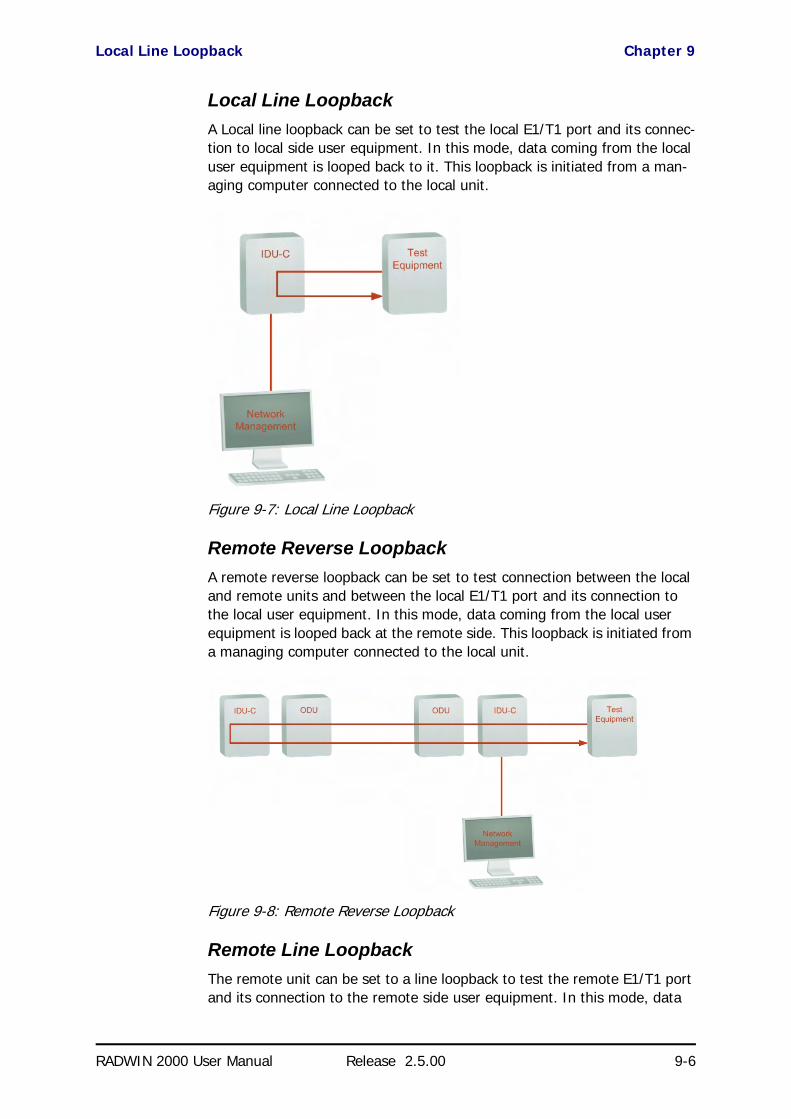
Local Line Loopback Chapter 9
RADWIN 2000 User Manual Release 2.5.00 9-6
Local Line LoopbackA Local line loopback can be set to test the local E1/T1 port and its connec-tion to local side user equipment. In this mode, data coming from the local user equipment is looped back to it. This loopback is initiated from a man-aging computer connected to the local unit.
Figure 9-7: Local Line Loopback
Remote Reverse LoopbackA remote reverse loopback can be set to test connection between the local and remote units and between the local E1/T1 port and its connection to the local user equipment. In this mode, data coming from the local user equipment is looped back at the remote side. This loopback is initiated from a managing computer connected to the local unit.
Figure 9-8: Remote Reverse Loopback
Remote Line LoopbackThe remote unit can be set to a line loopback to test the remote E1/T1 port and its connection to the remote side user equipment. In this mode, data

Local Internal Loopback Chapter 9
RADWIN 2000 User Manual Release 2.5.00 9-7
coming from the remote user equipment is looped back to it locally. This loopback is initiated by the managing computer connected to the local unit.
Figure 9-9: Remote Line Loopback
Local Internal LoopbackThe local unit can be set to close a remote loopback to test connection between the local and remote units and between the remote E1/T1 port and its connection to the remote user equipment. In this mode, data com-ing from the remote user equipment is looped back to it locally. This loop-back is initiated by the managing computer connected to the local unit.
Figure 9-10: Local Reverse Loopback
Reinstalling and Realigning a LinkIt may be necessary to reinstall the link if the ODUs need to be realigned.
To reinstall the link:
1. Choose a site.
The Configuration dialog box opens.
Note
Activating Install Mode causes both sites to go into install mode, causing disruption in service for approximately fifteen seconds.
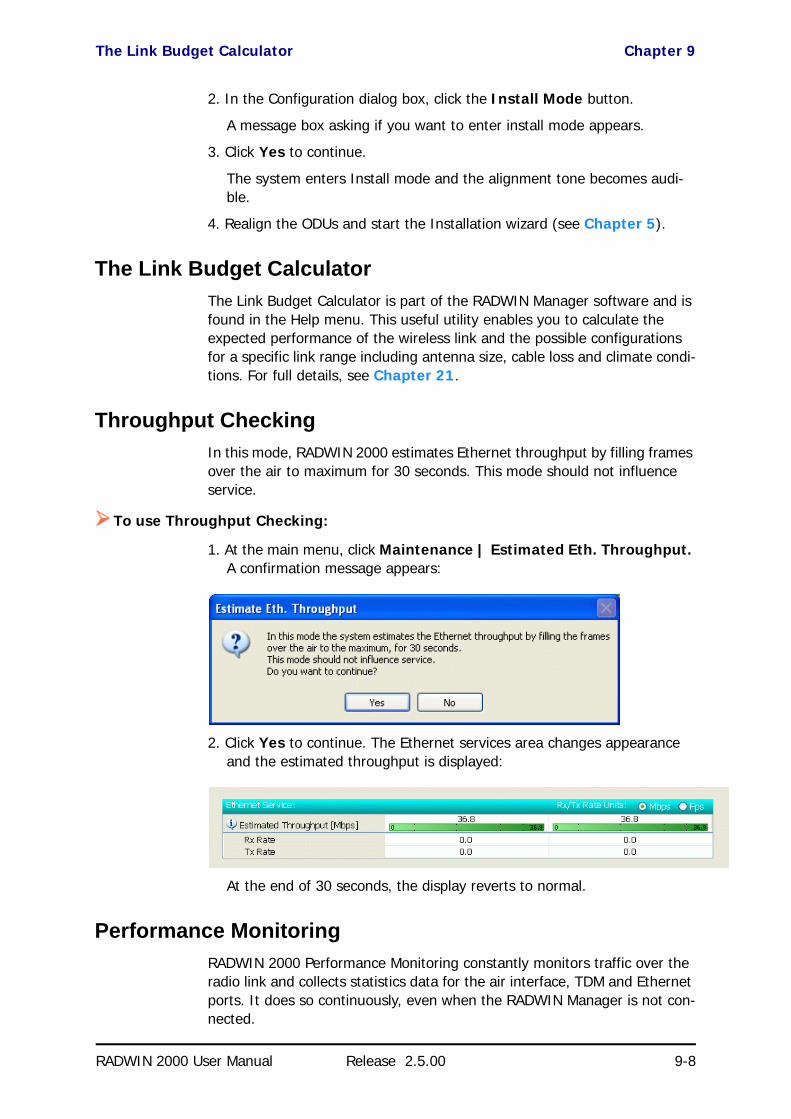
The Link Budget Calculator Chapter 9
RADWIN 2000 User Manual Release 2.5.00 9-8
2. In the Configuration dialog box, click the Install Mode button.
A message box asking if you want to enter install mode appears.
3. Click Yes to continue.
The system enters Install mode and the alignment tone becomes audi-ble.
4. Realign the ODUs and start the Installation wizard (see Chapter 5).
The Link Budget CalculatorThe Link Budget Calculator is part of the RADWIN Manager software and is found in the Help menu. This useful utility enables you to calculate the expected performance of the wireless link and the possible configurations for a specific link range including antenna size, cable loss and climate condi-tions. For full details, see Chapter 21.
Throughput CheckingIn this mode, RADWIN 2000 estimates Ethernet throughput by filling frames over the air to maximum for 30 seconds. This mode should not influence service.
To use Throughput Checking:
1. At the main menu, click Maintenance | Estimated Eth. Throughput. A confirmation message appears:
2. Click Yes to continue. The Ethernet services area changes appearance and the estimated throughput is displayed:
At the end of 30 seconds, the display reverts to normal.
Performance MonitoringRADWIN 2000 Performance Monitoring constantly monitors traffic over the radio link and collects statistics data for the air interface, TDM and Ethernet ports. It does so continuously, even when the RADWIN Manager is not con-nected.

The Monitor Log Chapter 9
RADWIN 2000 User Manual Release 2.5.00 9-9
Two types of logs are recorded:
• Monitor Log that records statistics on traffic rate and radio signal strength.
• Events Log that records when the rates fall above or below a pre-defined threshold. See page 9-14 below.
Both the statistics Monitor log and events log can be saved as text files.
The Monitor LogThe Monitor Log records performance statistics for predefined intervals. You can save the monitor log to a text file, as well as display the information in an on-screen report.
Saving the Monitor LogYou can save the recorded Monitor Log statistics to a text file.
To save the monitor log:
1. From the Tools menu, choose Preferences.
The Preferences dialog box appears:
Figure 9-11: Preferences dialog box
2. Click the Monitor Tab.
3. Select the file to save.
4. Click the check box to open the file for saving.
5. Click the button and in the Select File dialog box indicate in which folder and under what name the monitor log file is to be saved.
6. Set the time interval for adding data to the file.
7. Click OK to save the file.

The Monitor Log Chapter 9
RADWIN 2000 User Manual Release 2.5.00 9-10
Viewing Performance ReportsThe Performance Monitor Report displays performance views of each of the interfaces.
To obtain performance monitoring reports:
1. From the main menu, choose Tools | Performance Monitoring Report ...
You are presented with the following window:
Figure 9-12: Basic Performance Monitoring Report
2. Choose a report type from the left panel and click the Get Data toolbar button. For example, if you choose Site A, Air and Current, you will be offered a report looking like this:

The Monitor Log Chapter 9
RADWIN 2000 User Manual Release 2.5.00 9-11
Figure 9-13: A typical Performance Monitoring Report based on 15 minute intervals
Notice the Min RSL value of -100 on the fourth line. It Indicates that dur-ing the interval 12:30 to 12:45, there was a link sync loss. The next fig-ure shows the effect of a reset between 14:15 and 14:30.
Figure 9-14: Performance Monitoring Report showing the effect of a Reset
The prior data is invalidated as shown by the red crosses in the left hand column. Further, Min and Max RSL for the invalidated period is set to zero.
3. Click the Selection Pane icon to toggle the side panel on or off.
The other reports look similar. Here is a detailed description of the reports and their fields:
Several performance data occurrences are collected for each of the inter-faces (ES, SES, and UAS), as well as specific data per Interface type (e.g., Tx and Rx bytes for Ethernet). For the Air Interface, user defined thresholds data are collected. Refer to Table 9-3 and Table 9-4 below.
Data is collected and selectively displayed based on three time intervals as selected by the Interval radio buttons:

The Monitor Log Chapter 9
RADWIN 2000 User Manual Release 2.5.00 9-12
• Current (t=0)• 15 minutes Intervals• Daily
Table 9-3: Explanation of performance data
Data type Reported Value Explanation
Generic PM Data
UAS – Unavailable Seconds
Seconds in which the interface was out of service.
ES – Errored SecondsThe number of seconds in which there was at least one error block. Note that the notation of an error block is different per interface.
SES – Severe Errored Seconds
The number of seconds in which the service quality was low (the quality is different per type of interface and determined by the BBER threshold per interface).
BBE – Background Block Error
The number of errored blocks in an interval.
Integrity
A flag indicating that the data was valid. Note that the Performance Monitoring data is not valid if not all the values were stored (e.g., due to clock changes within the interval or power up reset).
Additional Air Interface PM Data
Max RSL The maximum of the receive signal level (measured in dBm).
Min RSL The minimum of the receive signal level (measured in dBm).
Max TSL The maximum of the transmit signal level (measured in dBm).
Min TSL The minimum of the transmit signal level (measured in dBm).
RSL Threshold 1The number of seconds in which the Receive Signal Level (RSL) was below the specified threshold.
RSL Threshold 2The number of seconds in which the RSL was below the specified threshold.
TSL ThresholdThe number of seconds in which the Transmit Signal Level (TSL) was above the specified threshold.
BBER ThresholdThe number of seconds in which the Background Block Error Ratio (BBER) exceeded the specified threshold.
Additional Ethernet Interface PM Data
Received BytesThe number of Megabytes received at the specified port within the interval
Transmitted BytesThe number of Megabytes transmitted at the specified port within the interval.
Throughput threshold Seconds count when throughput fell below the threshold
Traffic threshold Seconds count when actual traffic exceeded the threshold
TDM interface Active secondsThe number of seconds that the configured TDM services are active

The Monitor Log Chapter 9
RADWIN 2000 User Manual Release 2.5.00 9-13
Performance Monitoring Report ToolbarYou can use the toolbar to perform the actions described in the following table:
Setting Air Interface ThresholdsUse the Thresholds button on the Monitoring Performance Report toolbar to set the Air Interface Thresholds:
Figure 9-15: Threshold configuration dialog box
RSL Thresholds
Two RSL Thresholds can be defined. They are used as an indicator of prob-lems in the radio channel. You can check the RSS from the Link Budget Cal-culator results during installation. Values of -5dB and -8dB from the current RSS are typical.
TSL Threshold
A counter is maintained, of the number of second intervals during which Tx power exceeds this threshold.
BBER Threshold
The Background Block Error Ratio is measured as a percentage. The thresh-old can be set from 0.1% up to 50%.
For links with Ethernet only service, 8% threshold is recommended. If there are no problems during the interval, then for that threshold, the recom-
Table 9-4: Action of the toolbar buttons
Command Button Action
Get Data Gather current performance monitoring data.
Save Save current performance monitoring data to a file
Clear Clear current performance monitoring data
Thresholds Set Thresholds
Selection Pane Toggle on/off left panel
Close Closes the Performance Monitoring window

Events, Alarms and Traps Chapter 9
RADWIN 2000 User Manual Release 2.5.00 9-14
mended BBER value should be 0. Since the system provides a lossless Ethernet service, there is throughput degradation in case of interference. The degradation is proportional to the BBER.
Ethernet Thresholds - Capacity
This is used as a basis for checking adherence to a Service Level Agree-ment. It is the number of seconds count that the link capacity falls bellow the threshold.
Ethernet Thresholds - Traffic
The number of seconds count that received traffic exceeded this threshold. It can be used to measure traffic peaks.
Events, Alarms and Traps
The Events LogThe Events Log records system failures, loss of synchronization, loss of sig-nal, compatibility problems and other fault conditions and events.
Alarms (traps) are displayed in the Events Log in the lower panel of the main window. The Events Log may be saved as a text file.
The Events Log includes the following fields:
» Sequential number (ID)
» Date and time stamp
» Message
» Trap source
» IP address of the ODU that initiated alarm.
For complete information about traps and alarms see Appendix E.
The events are displayed in the Events Log in the lower right-hand panel of the RADWIN Manager main window:
Note
The foregoing event types include events from all links for which this managing computer has been defined as the traps address. Only events from RADWIN equipment will be shown.

The Events Log Chapter 9
RADWIN 2000 User Manual Release 2.5.00 9-15
Figure 9-16: Events Log Display
To save the Events Log:
1. From the Tools menu, choose Preferences.
The Preferences dialog box appears
2. Click the Events Tab.
3. Select the file to save.
4. Click the check box to open the file for saving.
Click the button and in the Select File dialog box indicate in which folder and under what name the Events Log file is to be saved, and click OK.
Note
To store the Events Log, first define the IP address, subnet mask, default gateway and trap destination address of the managing computer (see page 8-7 for details).
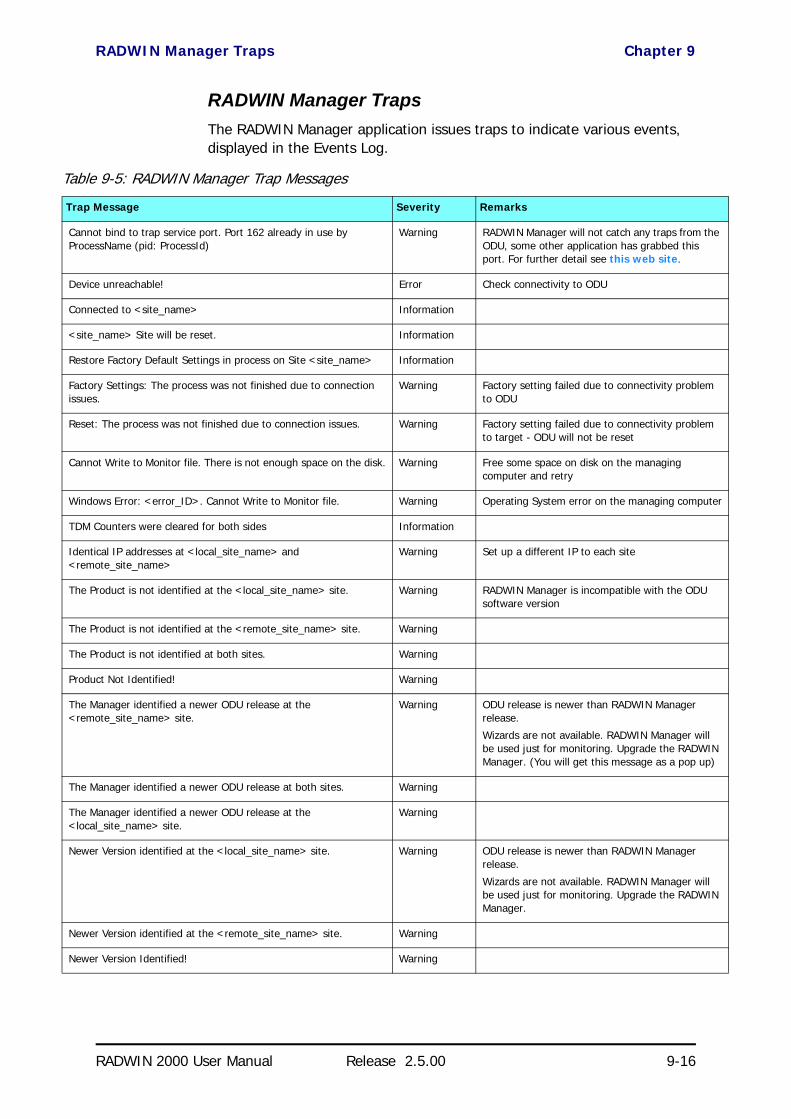
RADWIN Manager Traps Chapter 9
RADWIN 2000 User Manual Release 2.5.00 9-16
RADWIN Manager TrapsThe RADWIN Manager application issues traps to indicate various events, displayed in the Events Log.
Table 9-5: RADWIN Manager Trap Messages
Trap Message Severity Remarks
Cannot bind to trap service port. Port 162 already in use by ProcessName (pid: ProcessId)
Warning RADWIN Manager will not catch any traps from the ODU, some other application has grabbed this port. For further detail see this web site.
Device unreachable! Error Check connectivity to ODU
Connected to <site_name> Information
<site_name> Site will be reset. Information
Restore Factory Default Settings in process on Site <site_name> Information
Factory Settings: The process was not finished due to connection issues.
Warning Factory setting failed due to connectivity problem to ODU
Reset: The process was not finished due to connection issues. Warning Factory setting failed due to connectivity problem to target - ODU will not be reset
Cannot Write to Monitor file. There is not enough space on the disk. Warning Free some space on disk on the managing computer and retry
Windows Error: <error_ID>. Cannot Write to Monitor file. Warning Operating System error on the managing computer
TDM Counters were cleared for both sides Information
Identical IP addresses at <local_site_name> and <remote_site_name>
Warning Set up a different IP to each site
The Product is not identified at the <local_site_name> site. Warning RADWIN Manager is incompatible with the ODU software version
The Product is not identified at the <remote_site_name> site. Warning
The Product is not identified at both sites. Warning
Product Not Identified! Warning
The Manager identified a newer ODU release at the <remote_site_name> site.
Warning ODU release is newer than RADWIN Manager release.
Wizards are not available. RADWIN Manager will be used just for monitoring. Upgrade the RADWIN Manager. (You will get this message as a pop up)
The Manager identified a newer ODU release at both sites. Warning
The Manager identified a newer ODU release at the <local_site_name> site.
Warning
Newer Version identified at the <local_site_name> site. Warning ODU release is newer than RADWIN Manager release.
Wizards are not available. RADWIN Manager will be used just for monitoring. Upgrade the RADWIN Manager.
Newer Version identified at the <remote_site_name> site. Warning
Newer Version Identified! Warning

Setting the Events Preferences Chapter 9
RADWIN 2000 User Manual Release 2.5.00 9-17
Setting the Events PreferencesYou can define a color for the messages to be displayed in the Event Log window, according to the severity of the event. The severity is predefined.
To set the Message color:
1. From the Tools menu, choose Preferences.
The Preferences dialog box appears.
2. Click the Events Tab:
Figure 9-17: Preferences dialog box - Event tab
3. Select the event type and click on the button.
A color chart opens.
4. Select the required color.
5. Repeat for each of the event types.
To set the message background color:
• Click Background Color to change the text background.
To reset the message colors:
• Click Reset Settings to return to the default color settings.
Saving the Events LogYou can save recorded events in an Events Log text file. New alarms are automatically added to the text file, as they enter the Events Log.

Active Alarms Chapter 9
RADWIN 2000 User Manual Release 2.5.00 9-18
Active AlarmsUpon setting a trap destination, applicable events are reported as active alarms to the user. The active alarms are saved and can be viewed in the Active Alarms window.
To view summary of saved alarms:
1. From the Tools menu, choose Active Alarm Summary.
2. Choose either of the sites offered.
The Active Alarms Summary window opens:
Figure 9-18: Active Alarms Summary
The active alarms display does not update itself until the Refresh button is used.
The following table provides an explanation of the command buttons.
Viewing Recent EventsEach ODU stores the last 256 events:
Table 9-6: Active Alarms command buttons
Command Action
Save Saves the alarms in CSV or text format for further analysis
Refresh Shows the active alarms at the moment of refresh
Site Selects site for the active alarms
Close Closes the active alarm window

Reverting Alert Messages Chapter 9
RADWIN 2000 User Manual Release 2.5.00 9-19
To view the last 256 events:
1. Click Tools | Recent Events ... A window like the following is dis-played:
Figure 9-19: Recent Events - Up to last 256 events at Site A
2. Use the Site button to choose Site B
3. Use the Save button to store the events in a tab-delimited list.
Reverting Alert MessagesMany alert messages in the RADWIN Manager have an option of the form “Do not show this message again”. These alert messages can be reverted to their default state (shown) by choosing the Advanced tab from the Prefer-ences dialog:
Figure 9-20: Advanced Preferences
Just click the Restore Defaults button, followed by OK.

Other Advanced Preferences Chapter 9
RADWIN 2000 User Manual Release 2.5.00 9-20
Other Advanced Preferences
Enable and Disable Checking for Software UpdatesIf you are not on a network with Internet access, disable this.
Setting the RADWIN Manager LanguageIn the dialog of Figure 9-20, you can set the RADWIN Manager interface language, where other localizations are available.
Setting SNMP ParametersUse these choices to set the SNMP monitoring interval and time-out. These are only significant if you are using an SNMP based network management system such as RADWIN NMS.
Remote Power Fail IndicationRemote power fail indication indicates to one side that the other side has suffered a power failure. The failed site sends a final trap indication about the power loss just before powering off.
A “Dying-Gasp” circuit identifies the power failure at a minimum interval of 20 milliseconds before the ODU or IDU powers off. During that interval a message notifying the power failure is sent to opposite site. External alarm output number 4 indicates power failure at the opposite site.
TroubleshootingUse the following table to troubleshoot LED fault indications:
Table 9-7: LED fault indicators
LED Status Remedy
PWR Off Check that power is connected to the IDU
IDU Red Check that the IDU/ODU cable is properly wired and connected.
ODU Red Check that the IDU/ODU cable is properly wired and connected.
AIR I/F
Orange Complete the installation procedure from the RADWIN Manager
Red Check the antenna alignment. Check that the radio configuration of both site A and site B units are the same (Channel and Link ID).
SVCOrangeRedOff
Alarm detected at the Site B interface or Local or Remote loopbackAlarm detected at the Site A interfaceEthernet only IDU or E1/T1 not configured

Replacing an ODU Chapter 9
RADWIN 2000 User Manual Release 2.5.00 9-21
Use the following table to troubleshoot faults in the system:.
Replacing an ODUPrior to any action ensure that both ODUs have the same software version. You can see this on the inventory panels for each site.
For Site A, click Site A | Inventory and note the ODU software version. Repeat this for Site B using Site B | Inventory.
If either ODU has an old software version, perform a software upgrade. It is important to configure the new ODU identically to the old ODU to avoid con-figuration mismatches, which will disrupt the link.
An ODU may be reconfigured in several ways.
• Use the backup configurationIf a backup of the configuration is available, restore that configuration using Site A| Restore. Recall that backup files are linked to a MAC address. This won’t work for an identical replacement ODU.
• Manual configurationThe new ODU can be configured manually according to the link configuration. Remember to use the same settings for Link ID, channels, link password, IP addresses, and names.
HSS
Red
Orange
HSS not operational due to improper signal detection. This ODU is not transmitting
HSS is operational. One of the following conditions apply:• This ODU is a master that is generating signals and detecting signals• This ODU is a master that is generating signals but detected improper sig-
nals• This ODU is a client “Continue Tx” but is not detecting signals• This ODU is a client “Disable Tx” and is detecting signals from multiple
sources
All orange cases transmit.
STBYRed
OrangeMHS mode Primary, Link state not activeMHS mode Secondary, Link state active
Table 9-8: System Troubleshooting
Symptom Remedy
No powerEnsure that power is connected to the IDU
Ensure that the ODU cable is properly wired and connected
No signal
Complete the installation procedure from the RADWIN Manager
Check the antenna alignment. Check that the radio configuration of both site A and site B units is the same (channel settings and Link ID)
Weak signal received
Check the antenna alignment, reconfigure the link
Check the alignment tone sounds the Best Signal sequence
Table 9-7: LED fault indicators (Continued)
LED Status Remedy

Restoring Factory Setup Chapter 9
RADWIN 2000 User Manual Release 2.5.00 9-22
Restoring Factory SetupTo restore factory setup:
• Use Site Configuration A or B, and then Operations | Restore Defaults. Always restore the over-the-air site (B) first.
Online HelpOnline help can be accessed from the Help menu on the main window of the RADWIN Manager.
Customer SupportCustomer support for this product can be obtained from the local VAR, Inte-grator or distributor from whom it was purchased.
For further information, please contact the RADWIN distributor nearest to you or one of RADWIN's offices worldwide (see RADWIN Worldwide Offices at the beginning of this manual).

RADWIN 2000
Broadband Wireless Transmission System
USER MANUAL
RELEASE 2.5.00
Part 2: Site Synchronization
UM 2000-2500/09.10
RADWIN 2000 User Manual Release 2.5.00 10-1
Chapter 10
Hub Site SynchronizationWhat is Hub Site Synchronization?
When several units are collocated at a common hub site, interference may occur from one unit to another. RADWIN ODU units support the collocation of more than two units at a central site. Like any other RF deployment, the wireless operation is highly dependent on factors such as available frequen-cies, the physical spacing between radios, other interfering radios, and whether WinLink 1000 or RADWIN 2000 units are installed.
The RADWIN Hub Site Synchronization (HSS) method uses a cable con-nected from the master ODU to all collocated ODUs; this cable carries pulses sent to each ODU, which synchronize their transmission with each other. The pulse synchronization ensures that transmission occurs at the same time for all collocated units. This also results in all of the hub site units receiving data at the same time, eliminating the possibility of interference that could result if some units transmit while other units at the same loca-tion receive.
Figure 10-1 illustrates interference caused by non-synchronized collocated units.
Note
HSS does not eliminate the need for careful RF planning to ensure the design will work as planned. See Chapter 2 of the User Manual (both WinLink 1000 and RADWIN 2000) for information on installation site survey.
For WinLink 1000 units, Hub Site Synchronization support depends on the product model.

What is Hub Site Synchronization? Chapter 10
RADWIN 2000 User Manual Release 2.5.00 10-2
Figure 10-1: Interference caused by collocated units
Adding HSS removes interference as shown in the next two figures:
Figure 10-2: Collocated units using Hub Site Synchronization (1)
Figure 10-3: Collocated units using Hub Site Synchronization (2)
The units are connected to each other with HSS cables and HSS Distribution Units.
One of the radios in the site is defined as HSS Master and generates syn-chronization pulses.
The other collocated radios in the site - the HSS Clients, are connected to the HSS Master and synchronize their transmission to the pulses. An HSS Client can be configured to work in one of two modes:

Hardware Installation Chapter 10
RADWIN 2000 User Manual Release 2.5.00 10-3
• HSS Client-Continue Transmission (HSC-CT): If the unit loses synchronization with the HSS Master, the link remains active. How-ever, without synchronization pulses, it is possible that this unit will cause interference.
• HSS Client-Disable Transmission (HSC-DT): If the unit loses synchronization with the HSS Master, the link is dropped until the synchronization pulses resume. This setting prevents the unit from causing interference.
The remote ODUs that are not located at the hub site, are called Indepen-dent Units.
Hardware Installation
Connecting an HSS UnitA single HSS unit supports up to ten collocated ODUs. In addition to each unit being connected to its IDU or PoE device, the collocated unit has an additional cable that is connected to the HSS Unit. The HSS Unit is a com-pact, weatherproof (IP67) connector box that is installed on the same mast as the ODUs. All collocated units connect to this box using CAT-5e cable. Cables in prepared lengths are available for purchase.
The HSS unit is supplied with ten protective covers; any port not in use must be closed with a protective cover.
Figure 10-4: HSS Interconnection Unit
Note
WinLink 1000 radios used as independent units do not require HSS hardware.
Note
• For a single HSS unit, ensure that the collocated units are connected in sequence from SYNC 1. If an ODU is removed from the hub site, then all remaining ODUs must be reconnected to maintain the con-nectivity.
• You may cascade (daisy-chain) two or more HSS Units with an HSS cable. The method is described in detail below.

Using a Single HSS Unit Chapter 10
RADWIN 2000 User Manual Release 2.5.00 10-4
To connect an ODU to an HSS unit:
1. Unscrew the protective cover from the port marked SYNC 1.
2. Connect the RJ-45 connector from one end of the prepared CAT-5e cable to SYNC 1.
3. Connect the other end of the CAT-5e cable to the ODU connector labeled SYNC.
4. Tighten the protective seal that is on the prepared cable over the RJ-45 connector.
5. Repeat for all ODUs that are to be collocated at the hub site. The next ODU to be connected is inserted in SYNC 1, SYNC 2, followed by SYNC 3 and so on.
Using a Single HSS Unit
Figure 10-5: HSS Wiring schematic
The wiring, as shown in Figure 10-5 is self explanatory. The Sync signal path is less self evident. If we set ODU 1 (on SYNC 1) to HSS Master, then the Sync signal path is as shown in Figure 10-6. The signal travels from ODU 1 to SYNC 1, from SYNC 1 to SYNC 2, from SYNC 2 to ODU 2 and back again. The back and forth paths repeat for the second to fourth ODU, from left to right. The signal exits the HSS unit at SYNC 5 and terminates in ODU 5.
The choice of the ODU on SYNC 1 as HSS master is not mandatory, but is good practice. If for example we were to use ODU 3 as HSS master, the Sync signal path would be ODU 3 to SYNC 3, then left and right to SYNC 2 and SYNC 4. It would then propagate to ODUs 2 and 4, terminating at both ODUs 1 and 5.
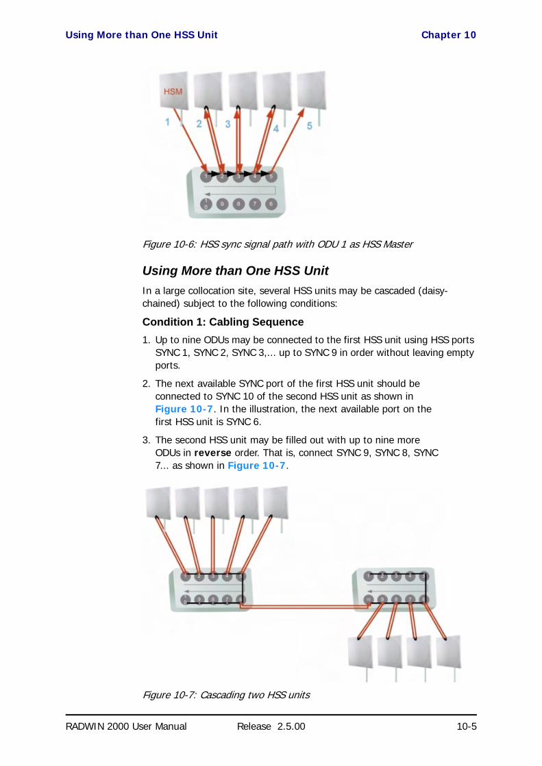
Using More than One HSS Unit Chapter 10
RADWIN 2000 User Manual Release 2.5.00 10-5
Figure 10-6: HSS sync signal path with ODU 1 as HSS Master
Using More than One HSS UnitIn a large collocation site, several HSS units may be cascaded (daisy-chained) subject to the following conditions:
Condition 1: Cabling Sequence1. Up to nine ODUs may be connected to the first HSS unit using HSS ports
SYNC 1, SYNC 2, SYNC 3,... up to SYNC 9 in order without leaving empty ports.
2. The next available SYNC port of the first HSS unit should be connected to SYNC 10 of the second HSS unit as shown in Figure 10-7. In the illustration, the next available port on the first HSS unit is SYNC 6.
3. The second HSS unit may be filled out with up to nine more ODUs in reverse order. That is, connect SYNC 9, SYNC 8, SYNC 7... as shown in Figure 10-7.
Figure 10-7: Cascading two HSS units

Using More than One HSS Unit Chapter 10
RADWIN 2000 User Manual Release 2.5.00 10-6
4. To add a a further HSS unit: Connect the next available SYNC port from the second HSS unit in descending order (SYNC 5 in Figure 10-7) to SYNC 1 of the third HSS unit.
5. ODUs are connected to the third HSS unit from SYNC 2 as shown in Figure 10-8, in ascending order:
Figure 10-8: Cascading three HSS units
6. If further ODUs are required, observe the convention that additional even numbered units are populated in descending order from SYNC 9 and odd numbered HSS units are populated in ascending order from SYNC 2.
Condition 2: Total HSS Cable LengthThe total path of the HSS sync pulse must not exceed 300m. This applies no matter how many HSS units are used. To illustrate the method for calculat-ing the sync pulse path length we show three examples. For our purpose, let:
Lmn denote the length of the ODU-HSS unit cable at SYNC n on HSS unit m
Hm be the length of the cable joining HSS unit m to HSS unit m+1
One HSS unit with five collocated ODUs
Two cascaded HSS units as shown in Figure 10-7
Note
If an ODU is disconnected from an HSS unit, then all remaining ODUs must be moved up or down to maintain the connectivity.
PathLength L11 2 L12 2 L13×+× 2 L14 L15+×+ +=
PathLength L11 2 L12 2 L13 2 L14×+×2
+L15×
+×H1 2 L29 2+× L28 2+ L27× L26+×
++ +
=
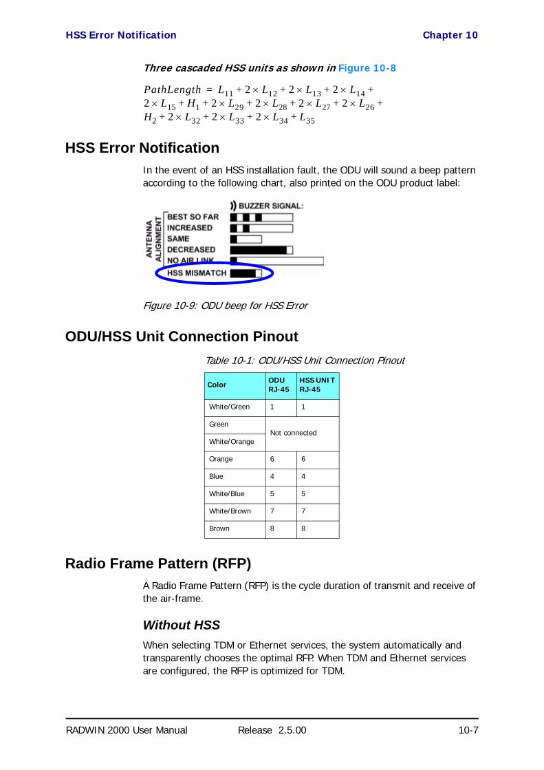
HSS Error Notification Chapter 10
RADWIN 2000 User Manual Release 2.5.00 10-7
Three cascaded HSS units as shown in Figure 10-8
HSS Error NotificationIn the event of an HSS installation fault, the ODU will sound a beep pattern according to the following chart, also printed on the ODU product label:
Figure 10-9: ODU beep for HSS Error
ODU/HSS Unit Connection Pinout
Radio Frame Pattern (RFP)A Radio Frame Pattern (RFP) is the cycle duration of transmit and receive of the air-frame.
Without HSSWhen selecting TDM or Ethernet services, the system automatically and transparently chooses the optimal RFP. When TDM and Ethernet services are configured, the RFP is optimized for TDM.
Table 10-1: ODU/HSS Unit Connection Pinout
Color ODU RJ-45
HSS UNIT RJ-45
White/Green 1 1
GreenNot connected
White/Orange
Orange 6 6
Blue 4 4
White/Blue 5 5
White/Brown 7 7
Brown 8 8
PathLength L11 2 L12 2 L13 2 L14×+×2
+L15×
+×H1 2 L29 2+× L28 2+ L27× 2 L× 26+×
H2 2 L32 2 L33 2 L34 L35+×+×+×
++ + +
+
=

RFP and HSS Chapter 10
RADWIN 2000 User Manual Release 2.5.00 10-8
RFP and HSSWhen HSS is used, the RFP for the collocated radios must be selected man-ually.
Both WinLink 1000 and RADWIN 2000 use the Time Division Duplex (TDD) mechanism.
Under HSS, TDD enables synchronization of transmission for the collocated units as shown in Figure 10-10:
Figure 10-10: Radio Frame Pattern
Five RFP types (A to E) are available. Under HSS the RFP must be config-ured by the user depending on the type of the radio products, services and channel bandwidth in accordance with the Table 10-2 and Table 10-3.
The tables describe the efficiency of the air interface according to the RFP type, radio products mix, services and channel bandwidth. The tables may also be viewed in the RADWIN Manager and in the Link Budget Calculator for both WinLink 1000 and RADWIN 2000. The efficiency of the air interface will vary according to the product used.
Legend:
Fit - available RFP for TDM and Ethernet services.
Best - optimal RFP for TDM and Ethernet services.
N/A - service unavailable
Table 10-2: Radio Frame Pattern Table - RADWIN 2000
RFP 40 MHz 20 MHz 10 MHz
TDM Ethernet TDM Ethernet TDM Ethernet
B Fit Fit Fit Fit Fit Fit
E Best Best Best Best Best Best
Table 10-3: Radio Frame Pattern Table - WinLink 1000
RPF 20 MHz 10 MHz 5 MHz
TDM Ethernet TDM Ethernet TDM Ethernet
A Best Best Fit Fit N/A N/A
B N/A N/A Best Fit Best Fit
C N/A N/A N/A Best N/A Fit
D N/A N/A N/A N/A N/A Best
E Fit Fit Fit Fit N/A N/A

RFP: General Radio Frame Pattern Chapter 10
RADWIN 2000 User Manual Release 2.5.00 10-9
Select the RFP that gives you the Best or Fit for required system services and select the channel bandwidth accordingly.
RFP: General Radio Frame PatternWhen setting the RPF, the following considerations should be borne in mind:
• When synchronizing RADWIN 2000 units you must use RFP B or E• If you mix RADWIN 2000 and WinLink 1000 units in a collocated
site, you must use RFP B or E• Selection of the RFP influences the capacity, latency and TDM quality • RFP influences capacity and latency. Jitter buffer configuration can
be used to set the TDM quality (see Chapter 5, TDM Services selection)
• Using the Link Budget Calculator, you can see the affect of the RFP on the Ethernet throughput.
RFP: RADWIN 2000 Considerations• The performance of RADWIN 2000 radios that operate with RFPs B
or E can be seen in the Link Budget Calculator. • For RADWIN 2000 C series: If the HSS Master works in asymmetric
Tx/Rx ratio, then all other collocated RADWIN 2000 units must oper-ate in the same Tx/Rx ratio. In this case the ratio will be fixed and not automatic-adaptive.
• Installation/Configuration considerations: If you are using RADWIN 2000 C master and RADWIN 2000 clients, the Services and Rates dialog will look like this:
NoteThe RFP must be the same for each link within the collocated system.

RFP: RADWIN 2000 Considerations Chapter 10
RADWIN 2000 User Manual Release 2.5.00 10-10
Figure 10-11: Services and Rates - RADWIN 2000 C master, RADWIN 2000 clients
• The circled areas should not be used. Using those areas, you may loose the collocated link with the longest distance between sites. If you do move the slider into a circled area, you will receive a popup warning:

RFP: RADWIN 2000 Considerations Chapter 10
RADWIN 2000 User Manual Release 2.5.00 10-11
Figure 10-12: Services and Rates - RADWIN 2000 C master, RADWIN 2000 clients - Extreme asymmetric allocation
By restricting one direction into the restricted area, the more distant sites may not even be able to sustain the link much less send or receive data.
• Asymmetric Allocation and Collocation: If the link is collocated, the use of Asymmetric Allocation is limited.The effective available range for Asymmetric Allocation (between the two circled tick in Figure 10-11) is primarily determined by three factors:• The RFP in use (B or E)
• Channel Bandwidth• Link distance
The first two parameters are entered during Link Installation/Configuration.
• Possible scenarios are shown in Table 10-4.Whenever Asymmetric Allocation is available, it is static for all traffic conditions.

RFP: WinLink 1000 Considerations Chapter 10
RADWIN 2000 User Manual Release 2.5.00 10-12
RFP: WinLink 1000 Considerations• When WinLink 1000 radios are collocated with RADWIN 2000 radios
using HSS, all radios must use RFP B or E. • The performance of WinLink 1000 radios that operate with these
RFPs can be seen in the Link Budget Calculator.
• The choice of the unit to be the HSS master is a matter of conve-nience. There is no technical reason to prefer a WinLink 1000 over a RADWIN 2000 as HSS master or vice versa. It is however, recom-mended that you use the RADWIN 2000 as master, since it will enforce the correct RFP on the other collocated units.
The following list summarizes the effect of using RFP B or E on WinLink 1000 radios. These effects should be taken into consideration when plan-ning new installations:
• Channel bandwidth 5 MHz is available under RFP E but is only sup-ported for ZZZZ Acceess products
• For products supporting a maximum throughput of 18.1 Mbps, the maximum Ethernet throughput is 14.5 Mbps at 20 MHz channel bandwidth and 9.3 Mbps at 10 MHz channel bandwidth
• For products supporting maximum throughput of 22.5 Mbps, the maximum Ethernet throughput is 21.4 Mbps at the 20 MHz channel and 9.3 Mbps at 10 MHz channel bandwidth
Table 10-4: Asymmetric Allocation with Collocated Links - Scenarios
HSS Master HSS Client Scenario: If you try to... Result Remarks
RADWIN 2000
WinLink 1000
Change master to asymmetric allocation
Link down Reversion to 50/50 restores link
RADWIN 2000
• Releases prior to 2.4 - Link down
• Release 2.4 later (RAD-WIN 2000 PDH and RADWIN 2000 L series) - Link down
• Release 2.4 and later (RADWIN 2000 C series) - TDM services stopped, link set to transmission ratio of master
Release 2.4 and later (RADWIN 2000 C series) - Asymmetric Allocation slider visible but cannot be changed
RADWIN 2000
WinLink 1000
RADWIN 2000Change client to asymmetric
Asymmetric Allocation slider not displayed
You cannot do this
WinLink 1000
WinLink 1000
RADWIN 2000Change client to asymmetric
Asymmetric Allocation slider not displayed
You cannot do this

HSS Status LED on the IDU-C and New Style IDU-E Chapter 10
RADWIN 2000 User Manual Release 2.5.00 10-13
HSS Status LED on the IDU-C and New Style IDU-EThe IDU-C and IDU-E have a front panel HSS status LED:
Link Configuration and HSSFor WinLink 1000 HSS-enabled units and all RADWIN 2000 units, the Hub Site Synchronization Settings dialog box appears in both the Link Installa-tion and Configuration Wizards.
Figure 10-13: HSS Settings: Left - WinLink 1000 client, Right - RADWIN 2000 master
The Synchronization Status dialog box displays the current status of each side of the link.
• Operation: Type of unit
Table 10-5: IDU-C and New Style IDU-E Front Panel LEDs for HSS
Color Function
Green This ODU is HSS master, generating signal, and HSS Sync is OK
Blinking Green
This ODU is a HSS client and in Sync
Red HSS not operational due to improper signal detection. This ODU is not transmitting
Orange
HSS is operational. One of the following conditions apply:• This ODU is a master that is generating signals and detecting signals• This ODU is a master that is generating signals but detected improper signals• This ODU is a client “Continue Tx” but is not detecting signals• This ODU is a client “Disable Tx” and is detecting signals from multiple sources
All orange cases transmit.
Off
HSS is not activated
HSS is not supported (WinLink 1000 only)
Disconnection between ODU and IDU

Link Configuration and HSS Chapter 10
RADWIN 2000 User Manual Release 2.5.00 10-14
• Hub Sync Master (HSM)• Hub Sync Client - Disable Transmission (HSC-DT)• Hub Sync Client - Continue Transmission (HSC-CT)
• Independent Unit
• Synchronization: • N/A- for Master or Independent Units
• Synchronized - for Hub Site Clients• Not Synchronized - for Hub Site Clients
• External Pulses:
To configure the Operational States of the Hub Site unit
1. Click the Enabled check box
2. Click the Configure button
The Hub Site Configuration dialog box with the current status of the ODUs is displayed.
3. Select the type of unit configuration from the drop-down list.
4. Select the appropriate RFP radio button. Some RFP options may be dis-abled depending on the bandwidth previously selected.
Note
Continue Transmission is intended to work if there is no HSM pulse. If a wrong HSM pulse is detected, a WinLink 1000 will resync, adapting to the HSM RFP and continue whereas RADWIN 2000 may stop.
Table 10-6: External Pulse Status
HSS Sync Status Meaning Color code
Generating ODU is HSM and generates the sync pulse
GreenDetected ODU is HSC and detects the sync pulse
Not detected ODU is independent
Generating and detected HSM, but other HSM present
OrangeGenerating and Improperly Detected
RADWIN 2000 ODU is HSM, but but detects a WinLink 1000 HSM signal that is not RFP E
Not detected HSC but no HSM present
Improperly detected
HSC but HSM pulse doesn’t fit the HSC as configured. Occurs only for RADWIN 2000, which stops transmitting.
Red
Note
Take care to avoid incorrect configuration of bandwidth, RFP or to set multiple Hub Sync Masters, as system interference can occur. RADWIN Manager provides error messages and tool tips if the system is configured with mismatches.
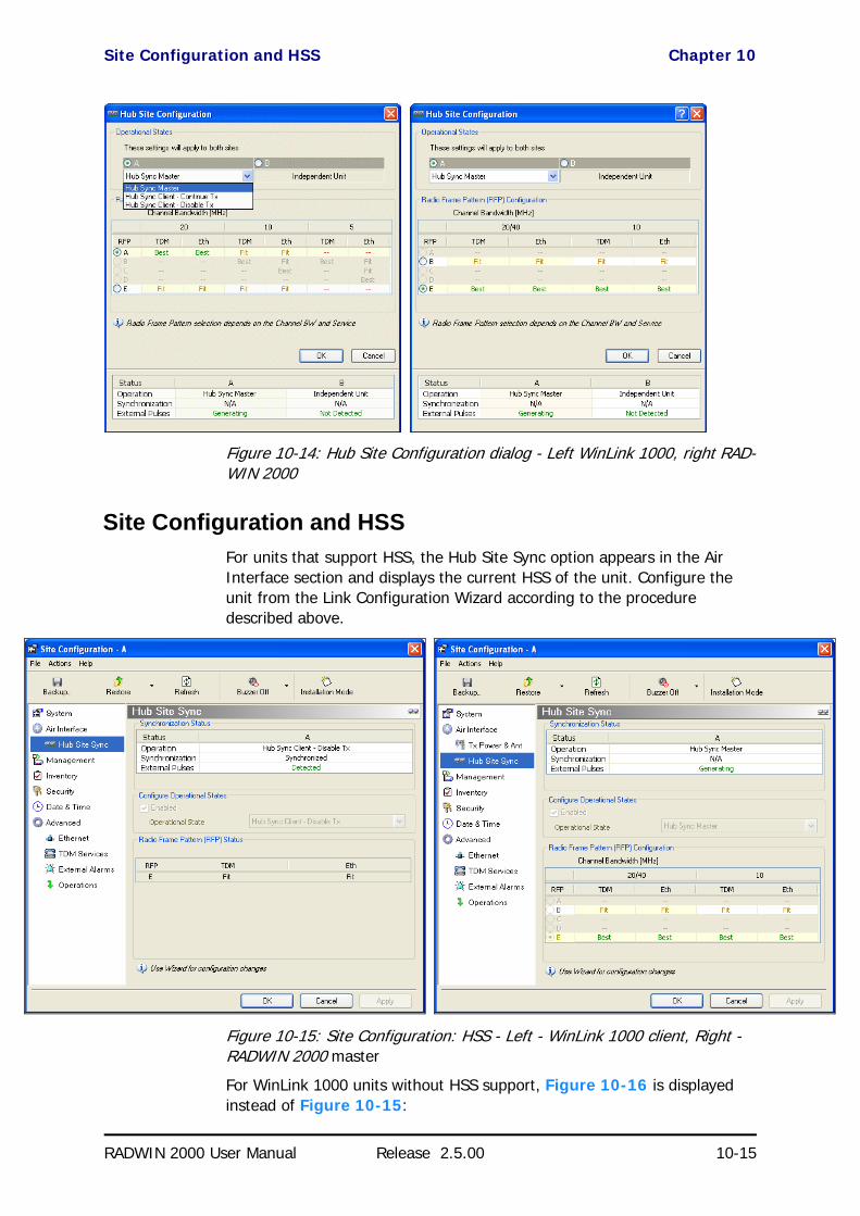
Site Configuration and HSS Chapter 10
RADWIN 2000 User Manual Release 2.5.00 10-15
Figure 10-14: Hub Site Configuration dialog - Left WinLink 1000, right RAD-WIN 2000
Site Configuration and HSSFor units that support HSS, the Hub Site Sync option appears in the Air Interface section and displays the current HSS of the unit. Configure the unit from the Link Configuration Wizard according to the procedure described above.
Figure 10-15: Site Configuration: HSS - Left - WinLink 1000 client, Right - RADWIN 2000 master
For WinLink 1000 units without HSS support, Figure 10-16 is displayed instead of Figure 10-15:

Site Configuration and HSS Chapter 10
RADWIN 2000 User Manual Release 2.5.00 10-16
Figure 10-16: HSS Not Supported

RADWIN 2000 User Manual Release 2.5.00 11-1
Chapter 11
Using the RADWIN GSUWhat is it for
The GPS-based synchronization unit (GSU) is designed to handle inter-site interferences under large-scale deployment scenarios.
The GSU is an outdoor unit consisting of a standard Wireless Link enclosure, a GPS antenna and a PoE device.
The GSU is connected to the HSS Unit using a standard HSS cable. It syn-chronizes the transmission timing of multiple Hub-Sites to the same clock source thus eliminating mutual interference.
GSU FunctionalityThe GSU receives a synchronization signal from the GPS once per second. It distributes a RADWIN proprietary synchronization signal to all other ODU units using the RS422 protocol and the standard HSS mechanism, where the GSU acts as an HSM unit.
When the GSU doesn’t receive a synchronization signal from the GPS for 30 seconds, it moves automatically to Self-Generation mode and acts as a reg-ular HSM unit, until the GPS recovers.
Typical GSU Scenarios
Independent Distributed SitesIn the scenario of Figure 11-1, we have multiple independent collocated sites, which may interfere with each other. To meet this situation, we coor-dinate all of them using the GSU as shown.
The GSU functions like “wide area HSS unit”, ensuring that all participating radios at the locations marked GSU each transmit and receive at the same time.pendent dis
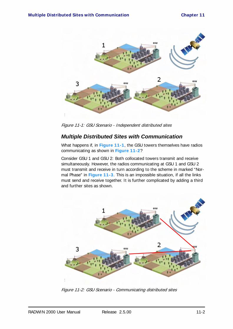
Multiple Distributed Sites with Communication Chapter 11
RADWIN 2000 User Manual Release 2.5.00 11-2
tributed sites
Figure 11-1: GSU Scenario - Independent distributed sites
Multiple Distributed Sites with CommunicationWhat happens if, in Figure 11-1, the GSU towers themselves have radios communicating as shown in Figure 11-2?
Consider GSU 1 and GSU 2: Both collocated towers transmit and receive simultaneously. However, the radios communicating at GSU 1 and GSU 2 must transmit and receive in turn according to the scheme in marked “Nor-mal Phase” in Figure 11-3. This is an impossible situation, if all the links must send and receive together. It is further complicated by adding a third and further sites as shown.
Figure 11-2: GSU Scenario - Communicating distributed sites

Cascaded Sites using Shifted Phase Transmission Chapter 11
RADWIN 2000 User Manual Release 2.5.00 11-3
Cascaded Sites using Shifted Phase TransmissionThe solution offered here is not a “universal cure”. The following conditions are necessary, but in any specific case may not be sufficient:
• The GSU sites (marked 1, and 3 above) are sufficiently far apart as to ensure that there is no mutual interference between communicat-ing sites (1-2 and 2-3 above)
• There should be no interference between non-communicating sites (1 and 3 above).
To see how it works, we use Figure 11-2. The GSU towers are numbered and marked for cascading, 1-2 and 2-3. There should not be a link between 1 and 3.
The GSU can synchronize the TDD timing of several sites enabling the cas-cading of consecutive links without mutual interference.
To use cascading, the TDD timing of the even-ordered links (GSU 2 above) must be “shifted” (Shifted Phase) and odd-ordered links (GSU 1 and GSU 3 above) must be “unshifted” (Normal Phase). The phase shift is half of the Radio Frame Duration (RFD) from the chosen RFP. The scheme is shown in Figure 11-3.
Since the GSU is always HSS master (HSM), at each GSU location, the GSU can “force” the synchronization of its collocated radios. By half RFD shifting, alternate collocated sites can talk to each other.
Figure 11-3: Phase shifted transmission - phase shift is 1/2 the RFD
Choice of normal or shifted phase is configurable per GSU using the RAD-WIN Manager.
GSU RedundancyThe GSU is designed to support redundancy, improving the robustness of a GSU based topology.
In redundancy mode, two GSUs are installed at the same HSS site. One of them self-configures to generate HSS sync signals. We will call it the Pri-mary unit. The other one, the Secondary unit remains dormant merely poll-ing the first GSU. If the Primary GSU fails, then the Secondary GSU becomes active immediately. If the Primary unit becomes active again, it remains dormant, reversing the original roles. The choice of the Primary GSU is random and of no significance.

GSU Kit Contents Chapter 11
RADWIN 2000 User Manual Release 2.5.00 11-4
If the Primary GSU fails, and then the Secondary GSU also fails to receive sync signals from its GPS, then it moves to self-generation HSM mode like an ordinary HSM ODU until its GPS recovers.
Figure 11-4: Make the GSUs the first two collocated units
Redundancy switching is completely transparent to the GSU-managed links.
GSU Kit ContentsThe GSU package includes:
• 1 x GSU• 1 x Mounting Kit
• 1 x GPS Antenna• 1 x GPS Antenna Mounting Kit• 1 x RF Cable, 1.5m
• CD
GSU Installation
OverviewThe GSU uses the same container and cabling as a WinLink 1000 unit.

Preparing the GSU for Use Chapter 11
RADWIN 2000 User Manual Release 2.5.00 11-5
Figure 11-5: General GSU configuration
In that respect, all of the considerations of Chapter 3, Chapter 17 and Chapter 18 apply to the GSU.
It may be configured using the regular RADWIN Manager or Telnet.
Preparing the GSU for UseUse the method of Chapter 19, Preloading an ODU with an IP Address to change the IP address from the default (10.0.0.120). In the example screen captures below, we use 192.168.222.20 with Subnet Mask 255.255.252.0.
Mounting the GSUMount the GSU and antenna. Ensure that its ODU port connected to its PoE device and the HSS cable is connected to the HSS unit as shown. The exter-nal LAN port of the PoE device is connected to the managing computer. If you are accessing the GSU through a network it is essential that you use the IP preloading method. The default IP address may be inaccessible and you may not use the Local Connection method over a network.
Configuring the GSUGetting StartedTo configure the GSU, you log on to it, exactly as in Chapter 4.
The GSU Main Window
Here is the main window for GSU configuration:
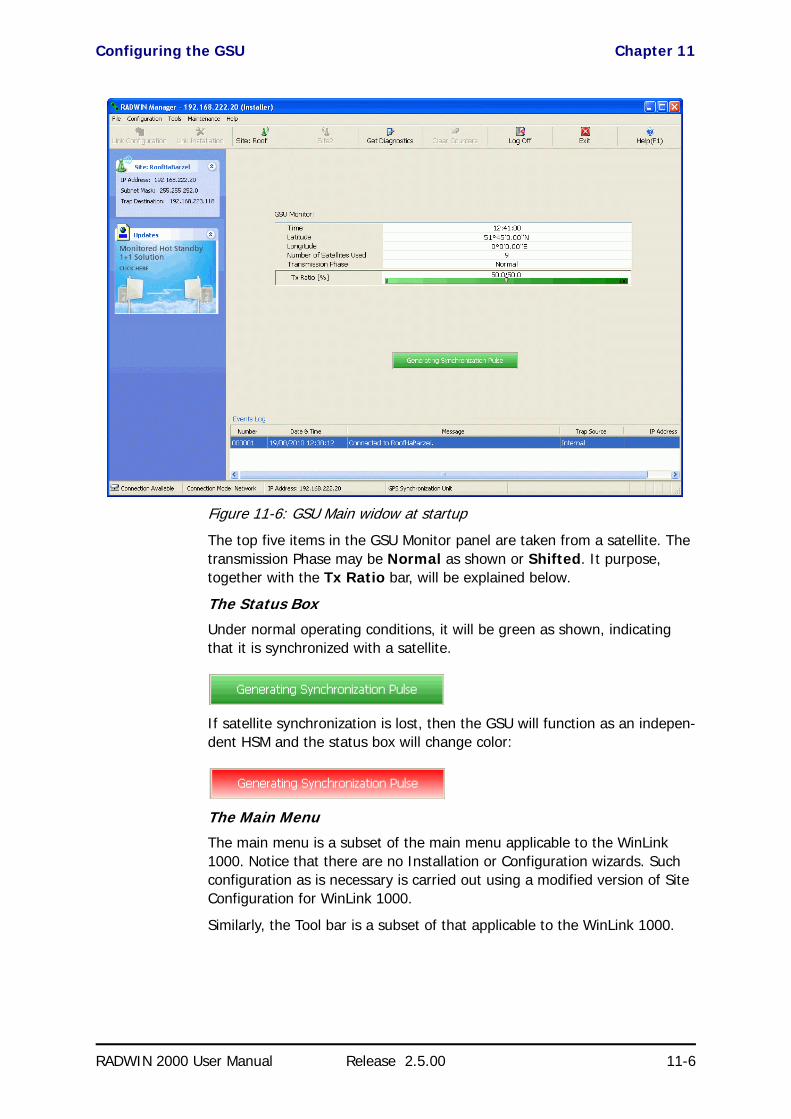
Configuring the GSU Chapter 11
RADWIN 2000 User Manual Release 2.5.00 11-6
Figure 11-6: GSU Main widow at startup
The top five items in the GSU Monitor panel are taken from a satellite. The transmission Phase may be Normal as shown or Shifted. It purpose, together with the Tx Ratio bar, will be explained below.
The Status Box
Under normal operating conditions, it will be green as shown, indicating that it is synchronized with a satellite.
If satellite synchronization is lost, then the GSU will function as an indepen-dent HSM and the status box will change color:
The Main Menu
The main menu is a subset of the main menu applicable to the WinLink 1000. Notice that there are no Installation or Configuration wizards. Such configuration as is necessary is carried out using a modified version of Site Configuration for WinLink 1000.
Similarly, the Tool bar is a subset of that applicable to the WinLink 1000.

Configuring the GSU Chapter 11
RADWIN 2000 User Manual Release 2.5.00 11-7
Using Site Configuration for the GSUSite Configuration: System
Here is the opening window for Site Configuration:
Figure 11-7: Site Configuration: System
It is similar to that of the WinLink 1000.
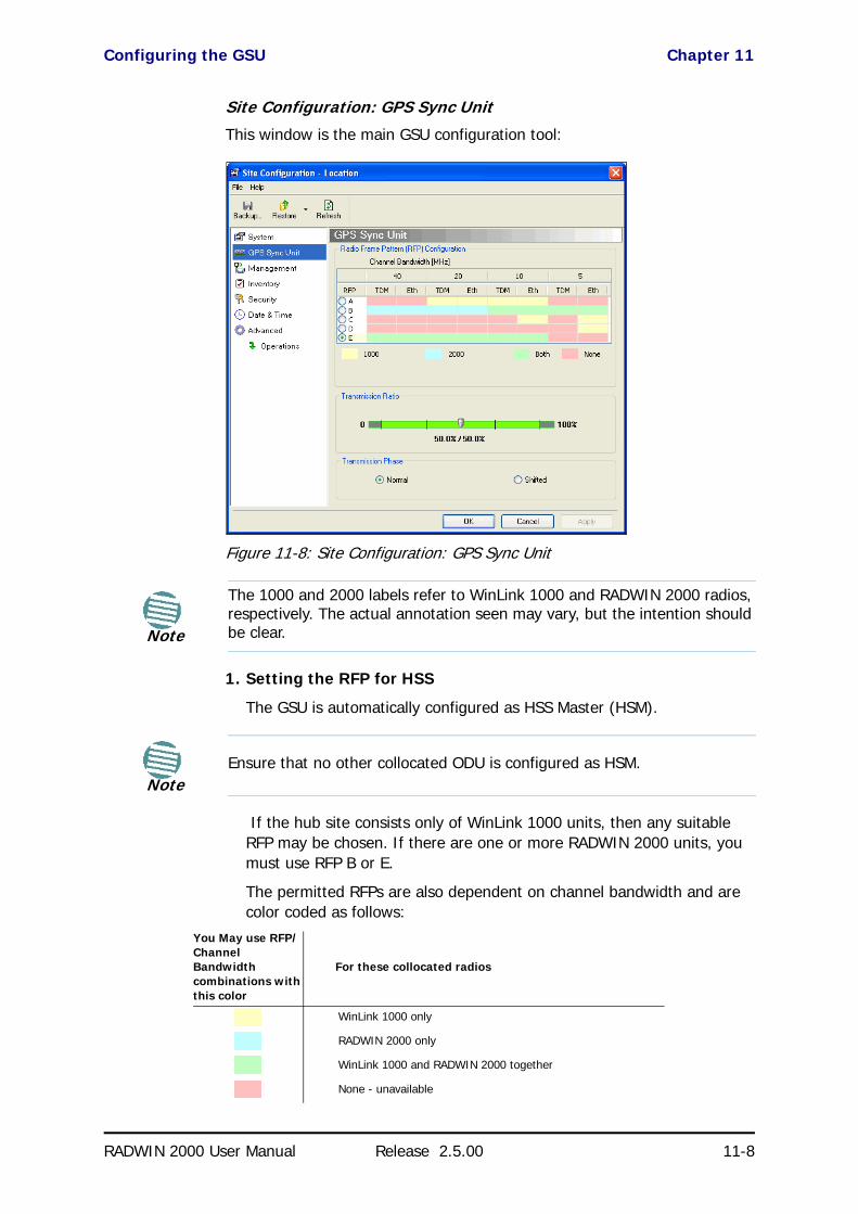
Configuring the GSU Chapter 11
RADWIN 2000 User Manual Release 2.5.00 11-8
Site Configuration: GPS Sync Unit
This window is the main GSU configuration tool:
Figure 11-8: Site Configuration: GPS Sync Unit
1. Setting the RFP for HSS
The GSU is automatically configured as HSS Master (HSM).
If the hub site consists only of WinLink 1000 units, then any suitable RFP may be chosen. If there are one or more RADWIN 2000 units, you must use RFP B or E.
The permitted RFPs are also dependent on channel bandwidth and are color coded as follows:
Note
The 1000 and 2000 labels refer to WinLink 1000 and RADWIN 2000 radios, respectively. The actual annotation seen may vary, but the intention should be clear.
NoteEnsure that no other collocated ODU is configured as HSM.
You May use RFP/Channel Bandwidth combinations with this color
For these collocated radios
WinLink 1000 only
RADWIN 2000 only
WinLink 1000 and RADWIN 2000 together
None - unavailable

Configuring the GSU Chapter 11
RADWIN 2000 User Manual Release 2.5.00 11-9
There is a further restriction: If there are two distributed sites transmit-ting to each other, they must both use the same RFP. This requirement, together with use of shifted transmission phase (item 3 below), ensures that communicating distributed sites to not interfere with each other by transmitting simultaneously.
Two GSU managed sites transmitting with shifted transmission phase and using the same RFP, transmit one half a RFD apart (see Figure 11-3 above).
2. Setting the Tx Transmission Ratio
Since the GSU is always HSM, it must be able to cater for hub site RAD-WIN 2000 C based links. (See the RADWIN 2000 User Manual, Chapter 5). If you use asymmetric allocation, shifted transmission phase becomes unavailable and you cannot “cascade” links as described in step 1.
3. Choosing the Transmission Phase
Chose the Transmission Phase in accordance with considerations in step 1 above. If you choose Shifted Phase then the Asymmetric Ratio selector is disabled.
Site Configuration: Management
Figure 11-9: Site Configuration: Management
Here you set the GSU IP address, subnet mask and gateway. You also set trap addresses here. It is identical to the corresponding panel for WinLink 1000.
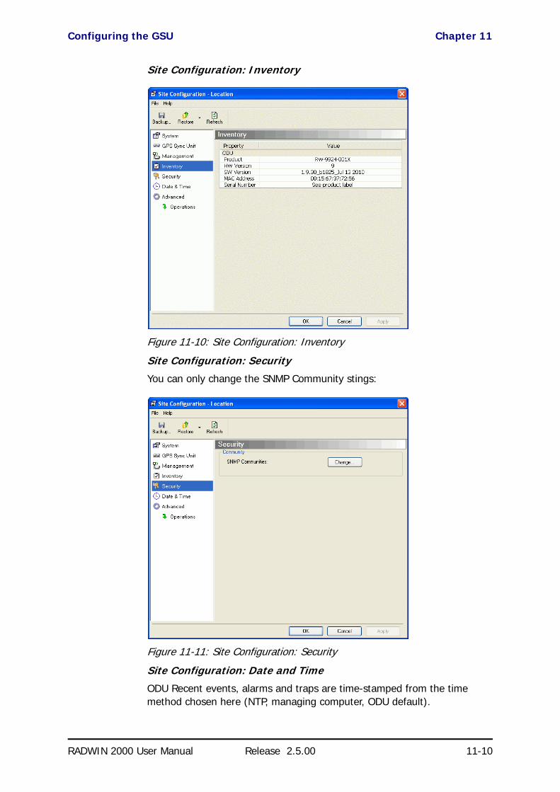
Configuring the GSU Chapter 11
RADWIN 2000 User Manual Release 2.5.00 11-10
Site Configuration: Inventory
Figure 11-10: Site Configuration: Inventory
Site Configuration: Security
You can only change the SNMP Community stings:
Figure 11-11: Site Configuration: Security
Site Configuration: Date and Time
ODU Recent events, alarms and traps are time-stamped from the time method chosen here (NTP, managing computer, ODU default).
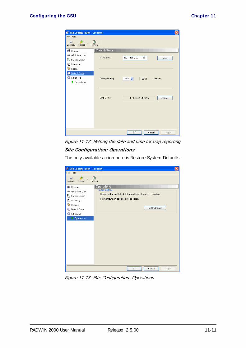
Configuring the GSU Chapter 11
RADWIN 2000 User Manual Release 2.5.00 11-11
Figure 11-12: Setting the date and time for trap reporting
Site Configuration: Operations
The only available action here is Restore System Defaults:
Figure 11-13: Site Configuration: Operations

GSU Preferences Chapter 11
RADWIN 2000 User Manual Release 2.5.00 11-12
GSU PreferencesThe Preferences window adds a new tab for the GSU:
Figure 11-14: Site Configuration: Operations
You may chose the units for latitude/longitude coordinates.
GSU Monitoring and DiagnosticsThe monitoring and diagnostic reports are similar to those of WinLink 1000.
GSU Telnet SupportTo configure the GSU with Telnet, start a Telnet session, using
telnet <GSU_ipaddr>.
For example, if you run Telnet as follows,
telnet 192.168.222.20
you will be asked for a user name and password. You must log on with administrator privilege under user name, admin and password netman.
The available commands are the same as for WinLink 1000 with the addi-tion of four additional display commands and three additional set com-mands.
The additional display commands are
display rfp
display ratio
display tx_phase
display gpsinfo
The last one display gpsinfo, is the most interesting:
[email protected]> display gpsinfo

Software Update for GSUs Chapter 11
RADWIN 2000 User Manual Release 2.5.00 11-13
Current GPS time 102941.000
Current GPS latitude 51.500000
Current GPS N\S Indicator N
Current GPS longitude 0.000000
Current GPS E\W Indicator E
Current GPS number of satellites 09
Current GPS altitude 84.0
Command "display gpsinfo" finished OK.
The three additional set commands are
set rfp <index> (2-6)
set ratio <ratio>
set tx_phase <mode:1=normal,2=shifted>
Software Update for GSUsAll GSUs in a distributed site can be updated simultaneously. Use an IP list as described in Chapter 14.

RADWIN 2000
Broadband Wireless Transmission System
USER MANUAL
RELEASE 2.5.00
Part 3: Advanced Installation
UM 2000-2500/09.10

RADWIN 2000 User Manual Release 2.5.00 12-1
Chapter 12
Monitored Hot StandbyInstallation Procedure
What is a RADWIN Monitored Hot StandbyThe RADWIN Monitored Hot Standby (MHS a.k.a 1+1) is a duplicated link set up as a primary link and a secondary link in hot standby mode as shown in Figure 12-1 below.
Figure 12-1: RADWIN Monitored Hot Standby
RADWIN MHS provides redundancy and backup to TDM services. It is designed to provide high reliability high-capacity Point-to-Point links. The RADWIN MHS is -

What RADWIN MHS provides Chapter 12
RADWIN 2000 User Manual Release 2.5.00 12-2
• Designed to provide redundancy and high reliability for carrier class operators
• Optimized for high capacity links operating in license-free bands
• A comprehensive solution providing protection against both equip-ment failure and loss of air interface, by simple connectivity between a primary link and a secondary link
The main service redundancy features of the RADWIN MHS are –
• TDM service cut-over from the primary to the secondary link is com-pletely automatic
• TDM service cut-over time no more than 50 ms• Automatic restore to primary link as soon as it becomes available
• Support for up to sixteen TDM channels for RADWIN 2000 and four TDM channels for WinLink 1000.
MHS is supported between -
• two WinLink 1000 links• two RADWIN 2000 links• a WinLink 1000 link and a RADWIN 2000 link.
What RADWIN MHS provides
Equipment ProtectionEquipment protection is provided for the electrically-active network ele-ments, ODU and IDU.
The primary IDU and the secondary IDU are connected by a cable to moni-tor failure and to control protection switching. Switching time is less than 50ms.
When connecting two WinLink 1000 links as 1+1, one dual-polarization antenna can be shared by the primary link and the secondary link.
Air-Interface ProtectionAir-Interface protection is unique to RADWIN and is optimized for wireless links operating in license-free bands.
The primary link and the secondary link use different frequency channels. If the air-interface of the primary link is disturbed and cannot carry the required TDM service, then the system automatically switches to the secon-dary link.
In addition, improved robustness and frequency planning flexibility is achieved, as the primary and secondary air interfaces can operate in the same frequency band or in different frequency bands.
Automatic Channel Selection (ACS) can be configured for each link to add additional robustness.

Purpose of this Chapter Chapter 12
RADWIN 2000 User Manual Release 2.5.00 12-3
The primary and secondary links are synchronized using Hub Site Synchro-nization (HSS).
It is recommended that both sites be installed with HSS cables. If HSS fails at one site, it can be operated from the other site by remote configuration.
Purpose of this ChapterThis chapter is an installation and maintenance guide for RADWIN MHS. It applies to all RADWIN radio products able to support the Monitored Hot Standby operational mode.
Who Should Read thisThis chapter is intended for persons responsible for the installation and maintenance of RADWIN MHS. To use it you need to know how to -
• Install a WinLink 1000 radio link• Install a RADWIN 2000 radio link• Use the RADWIN Manager software
RADWIN MHS Kit Contents• One Y-Connection Patch Panel• One MHS cable
Figure 12-2: RADWIN Y-Connection Patch Panel
Installing a RADWIN MHS
Figure 12-1 above is a schematic of a RADWIN MHS. Figure 12-3 shows how to connect the IDUs to the Patch Panel.
Note
The following procedure is substantially generic to all RADWIN radio products. Differences between WinLink 1000 and RADWIN 2000 class products will be stated explicitly. What you see on your running RADWIN Manager may differ in some details from the screen captures used to illustrate this chapter.
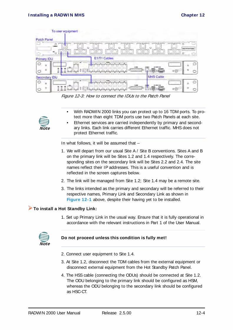
Installing a RADWIN MHS Chapter 12
RADWIN 2000 User Manual Release 2.5.00 12-4
Figure 12-3: How to connect the IDUs to the Patch Panel
In what follows, it will be assumed that –
1. We will depart from our usual Site A / Site B conventions. Sites A and B on the primary link will be Sites 1.2 and 1.4 respectively. The corre-sponding sites on the secondary link will be Sites 2.2 and 2.4. The site names reflect their IP addresses. This is a useful convention and is reflected in the screen captures below.
2. The link will be managed from Site 1.2; Site 1.4 may be a remote site.
3. The links intended as the primary and secondary will be referred to their respective names, Primary Link and Secondary Link as shown in Figure 12-1 above, despite their having yet to be installed.
To install a Hot Standby Link:
1. Set up Primary Link in the usual way. Ensure that it is fully operational in accordance with the relevant instructions in Part 1 of the User Manual.
2. Connect user equipment to Site 1.4.
3. At Site 1.2, disconnect the TDM cables from the external equipment or disconnect external equipment from the Hot Standby Patch Panel.
4. The HSS cable (connecting the ODUs) should be connected at Site 1.2. The ODU belonging to the primary link should be configured as HSM, whereas the ODU belonging to the secondary link should be configured as HSC-CT.
Note
• With RADWIN 2000 links you can protect up to 16 TDM ports. To pro-tect more than eight TDM ports use two Patch Panels at each site.
• Ethernet services are carried independently by primary and second-ary links. Each link carries different Ethernet traffic. MHS does not protect Ethernet traffic.
NoteDo not proceed unless this condition is fully met!

Installing a RADWIN MHS Chapter 12
RADWIN 2000 User Manual Release 2.5.00 12-5
5. Establish Secondary Link in the usual way, with HSS enabled. The two link frequencies should be at least 5MHz apart.
6. Connect the MHS cables at Sites A and B as shown in Figure 12-1 and Figure 12-3 above.
7. Run the Configuration Wizard for Primary Link. Activate TDM services in the usual way. Navigate to the Hot Standby tab, in the Services Config-uration panel:
Figure 12-4: Services Configuration Panel: Hot Standby mode selection
Check the Primary button to configure Primary Link as the primary link.
8. Complete the Wizard, and then move to Secondary Link.
9. Repeat step 7 for Secondary Link. For the Services Hot Standby tab, this time, check the Secondary button.
10. Complete the Wizard.
11. At Site 1.2, reconnect the Hot Standby Patch panel to the external equipment.
From this point on, we will simply refer to primary and secondary link (no capitalized names).
At the end of the process, the RADWIN Manager main windows should look like this:
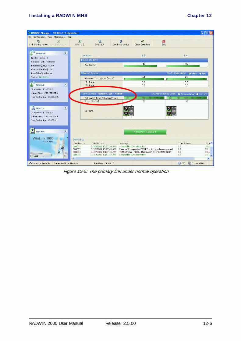
Installing a RADWIN MHS Chapter 12
RADWIN 2000 User Manual Release 2.5.00 12-6
Figure 12-5: The primary link under normal operation

Installing a RADWIN MHS Chapter 12
RADWIN 2000 User Manual Release 2.5.00 12-7
Figure 12-6: The secondary link under normal operation
To see what happens following a cut-over from the primary link to the sec-ondary link, you need to have running two copies of the RADWIN Manager – one logged into the primary link, and one logged into the secondary link.
Here then, is the situation after a cut-over to the secondary link:
For the primary link, the following window will appear for a few seconds:

Installing a RADWIN MHS Chapter 12
RADWIN 2000 User Manual Release 2.5.00 12-8
Figure 12-7: Primary link a few seconds before regular No-Link display
It will then revert to the standard No-Link-available window.
On the secondary link Manager window, you will see a window like this:
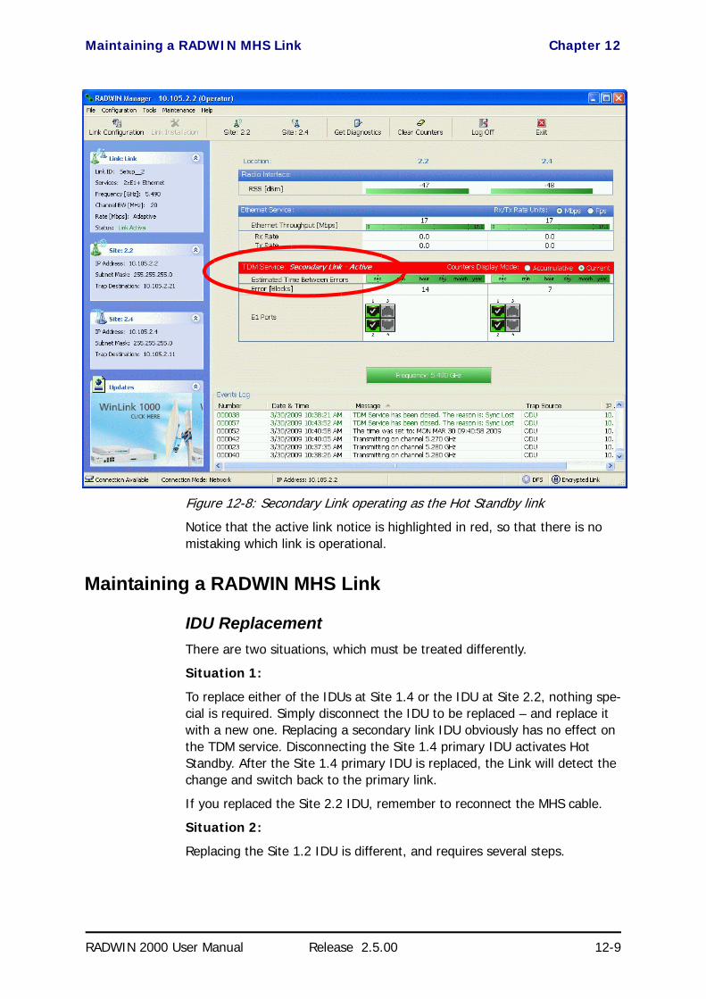
Maintaining a RADWIN MHS Link Chapter 12
RADWIN 2000 User Manual Release 2.5.00 12-9
Figure 12-8: Secondary Link operating as the Hot Standby link
Notice that the active link notice is highlighted in red, so that there is no mistaking which link is operational.
Maintaining a RADWIN MHS Link
IDU ReplacementThere are two situations, which must be treated differently.
Situation 1:
To replace either of the IDUs at Site 1.4 or the IDU at Site 2.2, nothing spe-cial is required. Simply disconnect the IDU to be replaced – and replace it with a new one. Replacing a secondary link IDU obviously has no effect on the TDM service. Disconnecting the Site 1.4 primary IDU activates Hot Standby. After the Site 1.4 primary IDU is replaced, the Link will detect the change and switch back to the primary link.
If you replaced the Site 2.2 IDU, remember to reconnect the MHS cable.
Situation 2:
Replacing the Site 1.2 IDU is different, and requires several steps.
ODU Replacement Chapter 12
RADWIN 2000 User Manual Release 2.5.00 12-10
To replace the Site 1.2 primary link IDU:
1. Power off the Site 1.2 IDU. This activates the secondary link using Hot Standby.
2. Run the Configuration manager on the secondary link, and in the Hot Standby panel of Figure 12-4 above, check the Disabled button.
3. Replace the Site 1.2 IDU without connecting it to the ODU (to prevent transmission by the primary link with the undefined IDU).
4. Reconnect the MHS cable between the IDUs at Site 1.2.
5. Again, run the Configuration Wizard on the secondary link, and in the panel of Figure 12-4 above, check the Secondary button to re-enable the link as secondary.
6. Connect the new Site 1.2 IDU to its ODU.
The Hot Standby will automatically revert to the primary link within 50ms.
ODU ReplacementBoth the primary and secondary replacement ODUs require pre-configura-tion prior to insertion into the link. The items to be pre-configured are
• HSS mode
• Link ID• Frequency• Hot Standby mode – using the new Services panel in Figure 12-4
above• IP address (optional)
To pre-configure an ODU:
1. Attach the new ODU to an IDU or a PoE device.
2. Run the RADWIN Manager and use Hot Standby tab of Figure 12-4 above to configure the new ODU to Primary or Secondary mode as required.
3. Ensure that it is set to the proper HSS mode in accordance with Figure 12-4 above. Enter the required Link ID and frequency.
To replace an ODU for primary or secondary link, at either site:
• Install the pre-configured ODU. (Since the other link is working normally, nothing need be done with it. If the secondary ODU was replaced, TDM service remains as is on the primary link. If the primary ODU was replaced, then the TDM service will shift back to the primary link.)
Note
Pre-configuration must be carried out before the new ODU is connected to its IDU. If you try to do it “live” against its IDU, it will cause spurious transmissions and a service break.

Switching Logic Chapter 12
RADWIN 2000 User Manual Release 2.5.00 12-11
Switching Logic
Switching from Primary Link to Secondary LinkSwitching from primary link to secondary link will occur following:
• Loss of the primary air interface due to sync loss• Loss of the primary air interface due to failure of the receiver to
acquire expected E1/T1 data during a period of 24ms• The Primary equipment (either ODU or IDU, local or remote) is pow-
ered off
Following the switch from the primary to the secondary link, the primary and secondary link Manager main windows should look like this:
Figure 12-9: Primary link after the switch over to secondary link (After a few seconds the display moves to No-Link display, with TDM ports grayed out.)

Switching back from the Secondary to the Primary Link Chapter 12
RADWIN 2000 User Manual Release 2.5.00 12-12
Figure 12-10: Secondary link operating after the switch over to secondary. (After a few moments the TDM icons become green.)
Switching back from the Secondary to the Primary LinkSwitching back from the secondary link to the primary link will occur after the primary link has become and remains fully functional for a continuous period of at least one second. Following reversion from the secondary link to the primary link, the Manager main windows should look like this:

Switching back from the Secondary to the Primary Link Chapter 12
RADWIN 2000 User Manual Release 2.5.00 12-13
Figure 12-11: Primary link operating after the switch back from secondary

System Operation description Chapter 12
RADWIN 2000 User Manual Release 2.5.00 12-14
Figure 12-12: Secondary Link operating after the switch back to Primary
System Operation description
Normal operation• TDM services are carried by the primary link • The secondary link (equipment and air interface) is operating but not carrying user traffic• TDM ports on the secondary IDUs are tri-state
Switching to backup
• Switching to secondary will occur in the following cases:• Loss of the primary air interface due to sync loss• Loss of the primary air interface due to failure of the receiver to acquire expected
TDM data during a period of 24ms• Primary equipment power off (either ODU or IDU, local or remote)
• The switching result would be:• TDM ports on the primary IDUs turn to tri-state • TDM ports on the secondary IDUs become active
Backup operation • TDM services are carried by the secondary link
Switching back to primary
• Switching back to primary will occur as soon as the Primary link is fully functional for 1 second

RADWIN 2000 User Manual Release 2.5.00 13-1
Chapter 13
The RADWIN EthernetRing
ScopeThe description of RADWIN Ethernet Ring in this Chapter is completely generic: Both WinLink 1000 and RADWIN 2000 links may participate in an Ethernet ring.
What is an Ethernet RingAn Ethernet ring consists of several nodes connected by hops (links). Loops are not allowed with Ethernet; therefore one hop is a Ring Protection Link (RPL) which “blocks” Ethernet traffic. In the event of failure in the ring, the Ring Protection Link unblocks and Ethernet traffic in the ring is restored.
Some terminology:• Normal State – all member links are functional except the RPL
which is blocked.• Blocked - the air-link is up but Ethernet traffic is not transmitted
across the link. The Ethernet service panel for the RPL in the RAD-WIN Manager is labeled Idle
• Unblocked - Ethernet traffic is transmitted across the RPL. The Ethernet service panel for the RPL in the RADWIN Manager is labeled Active
• Protection State – a member link is broken and the RPL passes Ethernet traffic
• Ring Protection Link - as described above• Ring Link - any member link controlled by the RPL
Caution
VLAN IDs are used by RADWIN products in three separate contexts: Management VLAN, Traffic VLAN and Ethernet Ring. It is recommended that you use different VLAN IDs for each context.
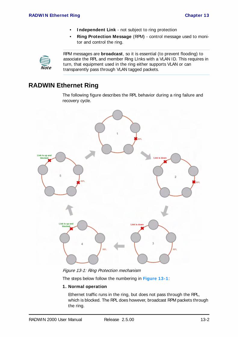
RADWIN Ethernet Ring Chapter 13
RADWIN 2000 User Manual Release 2.5.00 13-2
• Independent Link - not subject to ring protection• Ring Protection Message (RPM) - control message used to moni-
tor and control the ring.
RADWIN Ethernet RingThe following figure describes the RPL behavior during a ring failure and recovery cycle.
Figure 13-1: Ring Protection mechanism
The steps below follow the numbering in Figure 13-1:
1. Normal operation
Ethernet traffic runs in the ring, but does not pass through the RPL, which is blocked. The RPL does however, broadcast RPM packets through the ring.
Note
RPM messages are broadcast, so it is essential (to prevent flooding) to associate the RPL and member Ring LInks with a VLAN ID. This requires in turn, that equipment used in the ring either supports VLAN or can transparently pass through VLAN tagged packets.

RADWIN Ethernet Ring Chapter 13
RADWIN 2000 User Manual Release 2.5.00 13-3
2. Ring Link down, RPL notified
The RPL detects a link-down condition by the non-arrival of an RPM packet. It remains blocked for the Minimum time for failure detec-tion which is configurable using the RADWIN Manager (see page 13-9).
3. Ring Link down, RPL unblocked for traffic
The RPL unblocks for Ethernet traffic after the Minimum time for fail-ure detection expires and no RPM message has been received.
4. Ring Link restored but still blocked for traffic
The Ring Link is restored, but remains blocked for the Minimum time for recovery, set using the RADWIN Manager, to avoid rapid fluctua-tions leading to potential short term loops (see page 13-9).
5. Ring Link restored, RPL blocked for traffic
The RPL blocks to Ethernet traffic after the Minimum time for recov-ery expires and restores Ethernet traffic to the Ring Link (with a special RPM packet).
Return to 1.) Ring Link restored, RPL blocked for traffic
The ring is back to normal operation.
With RADWIN links, RADWIN’s Ring Protection solution prevents Ethernet loops in the ring at all times. The ring is always broken somewhere.
• Under a ring configuration a RADWIN Ring Link that was down and commences recovery, keeps blocking Ethernet traffic. The RPL iden-tifies this situation, blocks itself and then unblocks the other Ring Link. This is the transition from step 4 to 5 in Figure 13-1.
• If the failed hop is not a RADWIN link then there are two possibili-ties:
• If the hop Ring Link can signal that it is down by issuing a Loss of Signal (LOS) at the Ethernet port, then the RPL will control the RADWIN link connected to that port in the same manner as described above, to prevent an Ethernet loop.
• Otherwise, there may be a short loop period when the RPL is still open for traffic and the Ring Link is also unblocked during the Minimum time for recovery.

Ethernet Ring Topologies Supported by RADWIN Chapter 13
RADWIN 2000 User Manual Release 2.5.00 13-4
Ethernet Ring Topologies Supported by RADWINThe following ring topologies are supported:
Table 13-1: Topologies supported by RADWIN Ethernet Ring
Stand-alone ring
The ring is not connected to other rings
Single-homed ring
One of the nodes is connected to another network / ring:
Dual-homed ring
Two adjacent nodes are connected through a non-RADWIN link (e.g. micro wave or fiber):
Note:• The network has to be layer 2 and support VLANs• The ring control broadcasts RPM packets. Hence it is recommended to
prevent these packets from propagating into the network
Mixed ring
Some of the hops are connected through non-RADWIN links:

Protection Switching Chapter 13
RADWIN 2000 User Manual Release 2.5.00 13-5
Protection SwitchingProtection switching occurs upon failure in the ring.
The Ethernet service restoration time depends on the number of hops in the ring. With four hops the Ethernet service is restored in less than 50 ms.
In single and dual homed topologies the service restoration may take longer due to the aging time of the external switches. Switches that are immedi-ately aware of routing changes reduce the restoration time.
Hardware ConsiderationsEthernet Ring Protection is supported by the IDU-C, IDU-E and PoE.
A typical Ring Protection Link consists of an IDU-C or new style IDU-E, a PoE and two ODUs as shown in Figure 13-2. Hence one end of the RPL and of ring controlled links, as shown in Figure 13-2 has to be an IDU. It is recommended to have an IDU at each node to have the flexibility to change the RPL.
Repeater sites
Some of the hops are connected through RADWIN links with PoE devices, not supporting ring functionality:
Shared ring
RADWIN rings with shared hops.
Note:• A RADWIN link hop can be a part of up to 4 rings• The RPL cannot be a shared link• The two RPLs should use different Minimum Time for Activation values
to prevent duplicate action causing a loop
Table 13-1: Topologies supported by RADWIN Ethernet Ring (Continued)

Special Case: 1 + 1 Ethernet Redundancy Chapter 13
RADWIN 2000 User Manual Release 2.5.00 13-6
A ring node is built from two ODUs from adjacent links. The ODUs can be connected to either an IDU or to a PoE device as in Figure 13-2. Port names in the IDU are shown.
Figure 13-2: Node with IDU and PoE device
The switching function is carried out by the IDU-Cs and IDU-Es, both of which provide Layer 2 support (see Chapter 15).
Special Case: 1 + 1 Ethernet RedundancyThe same device may be used to provide economic 1 +1 redundancy for a single link.
A 1+1 Ethernet is a ring with two nodes. One of the links is RPL.
The equipment in a 1+1 Ethernet installation is as follows:
Figure 13-3: 1+1 Ethernet
NoteConnect the switch at the site only to one IDU.

Using RADWIN Manager to Set up a Ring Chapter 13
RADWIN 2000 User Manual Release 2.5.00 13-7
Figure 13-4: Using IDU-C or IDU-E with PoEs for the RPL
Notice that link content drops from four PoEs plus two switches to two PoEs and two IDU-Cs or IDU-Es.
Using RADWIN Manager to Set up a RingCreating a Ring using RADWIN Manager requires two stages:
6. Set up each participating link separately, in the usual way
7. For each link, run the Configuration wizard to define it as RPL or a Ring Link
Here then, is step 2 in more detail:
To integrate a link into an Ethernet Ring:
1. Using either the Installation or Configuration wizards, navigate to the Services window and chose the Ring tab.
Figure 13-5: Services window with Ring selected
2. Click Configure. The Ring definition window is displayed. The default is Independent Link and is used when the link is not part of any Ring.
Note
• The Ring uses a VLAN ID for the RPL. It is used to manage the Ring and nothing else; it is completely separate from the management and traffic VLANs referred to elsewhere
• A regular Ring Link may be a member of up to four rings and each of their RPL VLAN IDs must be configured

Using RADWIN Manager to Set up a Ring Chapter 13
RADWIN 2000 User Manual Release 2.5.00 13-8
Figure 13-6: Ring Options
3. To configure the link as a regular Rink link, click Rink Link (Non- RPL) and enter the ring LAN VIDs (at least one) to which it belongs and click OK:
Figure 13-7: Configuring Ring LAN VIDs
4. To configure the link as RPL, click Ring Protection Link (RPL) and enter its Ring VID.

Using RADWIN Manager to Set up a Ring Chapter 13
RADWIN 2000 User Manual Release 2.5.00 13-9
Figure 13-8: Configuring RPL VIDs
5. Enter the minimum times for failure detection and recovery.
For dual-homed configurations, where part of the ring goes through the core, if a core segment fails, the core should be allowed to recover before the RPL enters Protection State. Otherwise, it could happen that both the core and the RADWIN ring will switch in parallel. You should therefore, configure a Minimum time for failure detection high enough to take this possibility into account.
The Minimum time for recovery is a delay switch to prevent rapid “on-off” fluctuations. It functions like a delay switch use to protect elec-trical devices from rapid “on-off” power fluctuations, which in this con-text, may lead to potential short term loops .
6. Click OK to accept your settings.
The RPL will be clearly indicated in the RADWIN Manager. In the Link status area on the top left, you will see an Ethernet (Blocked) notice:
A Link-Idle message is displayed on the Ethernet Services Bar:
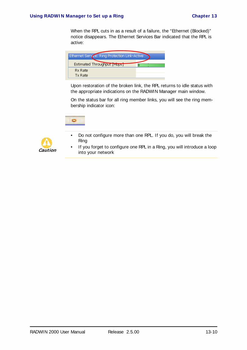
Using RADWIN Manager to Set up a Ring Chapter 13
RADWIN 2000 User Manual Release 2.5.00 13-10
When the RPL cuts in as a result of a failure, the “Ethernet (Blocked)” notice disappears. The Ethernet Services Bar indicated that the RPL is active:
Upon restoration of the broken link, the RPL returns to idle status with the appropriate indications on the RADWIN Manager main window.
On the status bar for all ring member links, you will see the ring mem-bership indicator icon:
Caution
• Do not configure more than one RPL. If you do, you will break the Ring
• If you forget to configure one RPL in a Ring, you will introduce a loop into your network

RADWIN 2000 User Manual Release 2.5.00 14-1
Chapter 14
VLAN Functionality withRADWIN 2000
VLAN Tagging - Overview
VLAN TerminologyBoth the technical literature and the RADWIN Manager use the terms VLAN ID and VID interchangeably to denote a VLAN identification number.
VLAN Background Information on the WEBThe standards defining VLAN Tagging are IEEE_802.1Q and extensions.
For general background about VLAN see http://en.wikipedia.org/wiki/IEEE_802.1Q.
Background information about Double Tagging also known as QinQ may be found here: http://en.wikipedia.org/wiki/802.1QinQ.
VLAN TaggingVLAN tagging enables multiple bridged networks to transparently share the same physical network link without leakage of information between net-works:
Figure 14-1: Two network using the same link with tagging

QinQ (Double Tagging) for Service Providers Chapter 14
RADWIN 2000 User Manual Release 2.5.00 14-2
IEEE 802.1Q is used as the encapsulation protocol to implement this mech-anism over Ethernet networks.
QinQ (Double Tagging) for Service ProvidersQinQ is useful for Service Providers, allowing them to use VLANs internally in their “transport network” while mixing Ethernet traffic from clients that are already VLAN-tagged.
Figure 14-2: Separating client data streams using double tagging
The outer tag (representing the Provider VLAN) comes first, followed by the inner tag. In QinQ the EtherType = 0x9100. VLAN tags may be stacked three or more deep.
When using this type of “Provider Tagging” you should keep the following in mind:
• Under Provider Tagging, the system double-tags egress frames towards the Provider’s network. The system adds a tag with a VLAN ID and EtherType = 0x9100 to all frames, as configured by the ser-vice provider (Provider VLAN ID).
• The system always adds to each frame, tags with VLAN ID and EtherType = 0x9100. Therefore,
• For a frame without a tag – the system will add a tag with VLAN ID and EtherType = 0x9100 so the frame will have one tag
• For a frame with a VLAN tag – the system will add a tag with VLAN ID and EtherType = 0x9100 so the frame will be double-tagged
• For a frame with a VLAN tag and a provider tag – the system will add a tag with VLAN ID and EtherType = 0x9100 so the frame will be triple-tagged and so on
VLAN UntaggingVLAN Untagging means the removal of a VLAN or a Provider tag.
Port FunctionalityThe VLAN functionality is supported by all LAN and SFP ports in the IDU.

Port Functionality Chapter 14
RADWIN 2000 User Manual Release 2.5.00 14-3
Each port can be configured how to handle Ethernet frames at the ingress direction (where frames enter the IDU) and at the egress direction (where frame exit the IDU).
The configuration is independent at each port.

Port Functionality Chapter 14
RADWIN 2000 User Manual Release 2.5.00 14-4
Ingress Direction
Egress Direction
Table 14-1: Port settings - Ingress direction
Transparent The port ‘does nothing’ with regard to VLANs - inbound frames are left untouched.
Tag
Frames entering the port without VLAN or QinQ tagging are tagged with VLAN ID and Prioritya, which are pre-configured by the user. Frames which are already tagged at ingress are not modified.
a. Priority Code Point (PCP) which refers to the IEEE 802.1p priority. It indicates the frame priority level from 0 (lowest) to 7 (highest), which can be used to prioritize different classes of traffic (voice, video, data, etc).
Table 14-2: Port settings - Egress direction
Transparent The port ‘does nothing’ with regard to VLANs - outbound frames are left untouched.
Untag all
All frames are untagged.
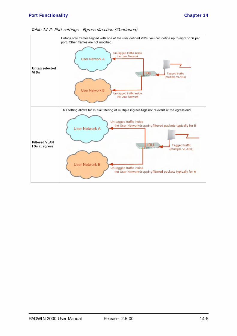
Port Functionality Chapter 14
RADWIN 2000 User Manual Release 2.5.00 14-5
Untag selected VIDs
Untags only frames tagged with one of the user defined VIDs. You can define up to eight VIDs per port. Other frames are not modified.
Filtered VLAN IDs at egress
This setting allows for mutial filtering of multiple ingrees tags not relevant at the egress end:
Table 14-2: Port settings - Egress direction (Continued)

VLAN Availability Chapter 14
RADWIN 2000 User Manual Release 2.5.00 14-6
VLAN AvailabilityVLAN is available for links using either WinLink 1000 or RADWIN 2000 radios. VLAN support requires the use of IDU-Cs or new style IDU-Es.
VLAN Configuration Using the RADWIN Manager
Provider tagging
With Provider tagging, the system double-tags egress frames towards the provider’s network. All frames are tagged QinQ with a VLAN ID, which is configured by the service provider (Provider VLAN ID).
With this setting, ingress frames which are not tagged with the configured Provider VLAN ID are blocked (filtered).
Note: Each port can be configured independently to a tagging mode. However, only a single Provider VLAN ID can be defined per IDU.
Provider tagging without filter
This setting functions like Provider tagging. However, all ingress frames are passed through.
Caution
VLAN IDs are used by RADWIN products in three separate contexts: Management VLAN, Traffic VLAN and Ethernet Ring. It is recommended that you use different VLAN IDs for each context.
Disclaimer
If you are not a VLAN expert, please be aware that incorrect VLAN configuration may cause havoc on your network. The facilities described below are offered as a service to enable you to get best value from your RADWIN 2000 links and are provided “as is”. Under no circumstances does RADWIN accept responsibility for network system or financial damages arising from incorrect use of these VLAN facilities.
Table 14-2: Port settings - Egress direction (Continued)

Management Traffic and Ethernet Service Separation Chapter 14
RADWIN 2000 User Manual Release 2.5.00 14-7
Management Traffic and Ethernet Service SeparationYou can define a VLAN ID for management traffic separation. You should configure the system to prevent conflicts as detailed below.
When configured for the default operational mode, a “Provider port” will handle ingress traffic as follows:
• Filters frames that are not tagged with the Provider VLAN ID
• Removes the Provider double tag
Therefore, if a port is configured for management traffic separation by VLAN and as ‘Provider port’, then the received management frames must be dou-ble tagged as follows:
• The outer tag has to be the Provider’s tag (so the frame is not fil-tered)
• The internal tag has to be management VLAN ID
To avoid mix-ups, best practice is to:
• Separate the management and data ports• Define only a data port with Provider function
All IDU-C and new style IDU-E models have two LAN ports so you can easily separate management and Ethernet service.
VLAN Tagging for Ethernet Service: ConfigurationVLAN Configuration is carried out per site. It is up to you to ensure consis-tency between the link sites. The discussion below is based on Site A how-ever, it also applies to Site B.
To set up VLAN tagging for Ethernet service, enter Site Configuration for Site A, choose the Ethernet tab and click the VLAN Configuration... but-ton (Figure 8-15). The following window is displayed:

VLAN Tagging for Ethernet Service: Configuration Chapter 14
RADWIN 2000 User Manual Release 2.5.00 14-8
Figure 14-3: VLAN tag settings
The choices for Ingress Mode are -
Figure 14-4: VLAN: Ingress modes
The two choices correspond respectively to the two rows of Table 14-1. Choosing Tag causes the VLAN ID and VLAN Priority fields to become avail-able:
NoteIf you are using a new style IDU-E, the SFP row will not appear.

VLAN Tagging for Ethernet Service: Configuration Chapter 14
RADWIN 2000 User Manual Release 2.5.00 14-9
Figure 14-5: VLAN: Ingress mode - setting VLAN ID and Priority
The choices for Egress Mode are -
Figure 14-6: VLAN: Egress modes
The five non-transpatarent choices correspond respectively to the five rows of Table 14-2 in the order, row 1, 2, 4, 5, 3.
The first two choices, Transparent and Untag all require no further action.
Untag selected VIDs causes the eight VLAN ID fields to become avail-able:
Figure 14-7: Untagging selected VIDs
You may nominate up to eight VIDs for untagging; beyond simple range checking, there is no other validation.
Both Provider tagging and Provider tagging without filter enable the Provider parameters fields:
Note
Throughout this chapter, all VLAN IDs must be between 1 and 4094, inclusive. All VLAN priorities must be between 0 and 6, inclusive. The values entered are range-checked. If for example, you enter a VLAN ID of 4095, then 4094 will be reflected back.

VLAN Tagging for Ethernet Service: Configuration Chapter 14
RADWIN 2000 User Manual Release 2.5.00 14-10
Figure 14-8: Provider parameters
There is of course only one Provider VLAN ID. It is most likely yours, as the Provider!
Filtered VLAN IDs enables you to filter and block only frames tagged with one of the user defined VIDs. You can define up to eight VIDs per port. Other frames are not modified and are forwarded transparently.
When you are finished, remember to click OK (Figure 14-3) to save your entries.

RADWIN 2000 User Manual Release 2.5.00 15-1
Chapter 15
Software UpgradeWhat is the Software Upgrade Utility?
The RADWIN Manager provides a Software Upgrade Utility (SWU) to upgrade the software (firmware) of installed ODUs in a network. The update files may be located anywhere accessible by the operator.
The SWU provides for:
• Prior backup of the current files prior to upgrade
• Upgrade from a list• Delayed upgrade• Various ODU reset options
The default location of the software files is in the installation area, and can be used to restore factory defaults.
Upgrading an Installed LinkTo upgrade software for a link:
1. In the RADWIN Manager main menu, click Tools | Software Upgrade ... The following detached window appears
NoteThe following procedure is generic to all RADWIN radio and GSU products.
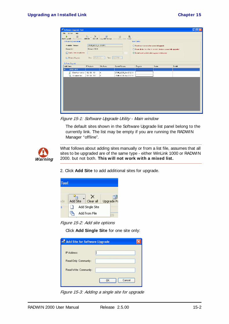
Upgrading an Installed Link Chapter 15
RADWIN 2000 User Manual Release 2.5.00 15-2
Figure 15-1: Software Upgrade Utility - Main window
The default sites shown in the Software Upgrade list panel belong to the currently link. The list may be empty if you are running the RADWIN Manager “offline”.
2. Click Add Site to add additional sites for upgrade.
Figure 15-2: Add site options
Click Add Single Site for one site only:
Figure 15-3: Adding a single site for upgrade
Warning
What follows about adding sites manually or from a list file, assumes that all sites to be upgraded are of the same type - either WinLink 1000 or RADWIN 2000. but not both. This will not work with a mixed list.

Upgrading an Installed Link Chapter 15
RADWIN 2000 User Manual Release 2.5.00 15-3
Enter the IP address of the site, the Community strings (Default: public and netman, respectively) and then click OK. The site will appear in the Software Upgrade list box. For example if we add the site at IP address 192.168.2.101, the SWU main window of Figure 15-1 looks like this:
Figure 15-4: Single site added for upgrade
The list can be cleared using the Clear All button.
As an alternative to adding sites one at a time, you can add sites from a prepared list using the Add from File option in Figure 15-2. The list has the following format:
<IP address>,<Read-Only community>,<Read-Write community>
Here is an example:
192.168.1.101,public,netman
192.168.1.102,public,netman
192.168.2.101,public,netman
192.168.2.102,public,netman
3. Having created an update list, click Upgrade Package to chose the rel-evant files. The default files are located in the SWU subdirectory in the RADWIN Manager installation area. They are currently named SWU_1k.swu and SWU_2k.swu. You may have to find them else-where, depending on your system.
4. You make limited changes to the list by right-clicking any line:

Upgrading an Installed Link Chapter 15
RADWIN 2000 User Manual Release 2.5.00 15-4
Figure 15-5: Software Upgrade site options
5. To back up your existing system, check Backup device software
check-box. Then click the button for a standard file dialog. The default location is the My Documents directory on the managing com-puter or the last backup directory you used.
6. In addition to the previous step, you may opt to perform a delayed upgrade. Check the Delayed Upgrade box, and enter the date and time for the delayed upgrade.
7. The radio buttons on the right determines how your sites should be reset. Bear in mind that on the one hand, a reset involves a service interrup-tion, but on the other hand, the software upgrade will not become effec-tive until after the reset is carried out.
8. Click Start Upgrade to commence the process. For an immediate upgrade you will be able to observe the upgrade progress from the green progress bars:
Figure 15-6: Software upgrade in progress - Note the stop button
Note
The backup here is the same as that in page 8-32, and serves the same purpose. It provides a fallback if the upgrade proves problematic.

Software Update for GSUs Chapter 15
RADWIN 2000 User Manual Release 2.5.00 15-5
Figure 15-7: Software upgrade completed successfully
9. Click Close to exit.
10. If you requested a delayed upgrade, a notice like this will appear in the SWU title bar:
Software Update for GSUsAll GSUs in a distributed site can be updated simultaneously. Use an IP list as described above.
Caution
If one or both sites fail to update, a warning notice will be displayed.
If one site of a link updates but the other fails, you should correct the problem and update the second site as soon as possible. If you do not, following the next reset of the updated site, you could experience a link software mismatch which may affect service. See page 9-3 for details.
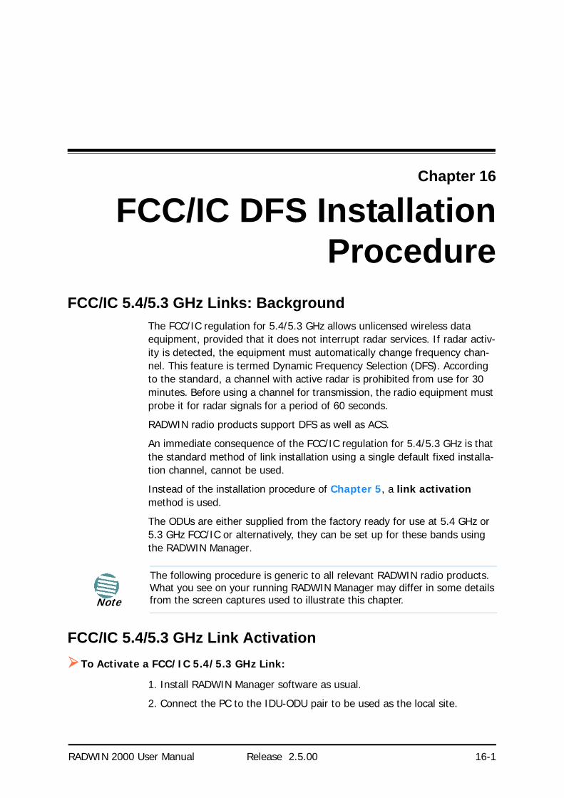
RADWIN 2000 User Manual Release 2.5.00 16-1
Chapter 16
FCC/IC DFS InstallationProcedure
FCC/IC 5.4/5.3 GHz Links: BackgroundThe FCC/IC regulation for 5.4/5.3 GHz allows unlicensed wireless data equipment, provided that it does not interrupt radar services. If radar activ-ity is detected, the equipment must automatically change frequency chan-nel. This feature is termed Dynamic Frequency Selection (DFS). According to the standard, a channel with active radar is prohibited from use for 30 minutes. Before using a channel for transmission, the radio equipment must probe it for radar signals for a period of 60 seconds.
RADWIN radio products support DFS as well as ACS.
An immediate consequence of the FCC/IC regulation for 5.4/5.3 GHz is that the standard method of link installation using a single default fixed installa-tion channel, cannot be used.
Instead of the installation procedure of Chapter 5, a link activation method is used.
The ODUs are either supplied from the factory ready for use at 5.4 GHz or 5.3 GHz FCC/IC or alternatively, they can be set up for these bands using the RADWIN Manager.
FCC/IC 5.4/5.3 GHz Link ActivationTo Activate a FCC/IC 5.4/5.3 GHz Link:
1. Install RADWIN Manager software as usual.
2. Connect the PC to the IDU-ODU pair to be used as the local site.
Note
The following procedure is generic to all relevant RADWIN radio products. What you see on your running RADWIN Manager may differ in some details from the screen captures used to illustrate this chapter.

FCC/IC 5.4/5.3 GHz Link Activation Chapter 16
RADWIN 2000 User Manual Release 2.5.00 16-2
3. Run the RADWIN Manager and log in as Installer. You will see the follow-ing window:
Figure 16-1: Activating an ODU - Inactive link
When the Manager Main Screen is displayed it appears with the Link Sta-tus label red and showing Inactive.
4. Click Site:Location | Air Interface for the logged in site.
5. The Air Interface dialog box opens:
Figure 16-2: Air Interface dialog box

FCC/IC 5.4/5.3 GHz Link Activation Chapter 16
RADWIN 2000 User Manual Release 2.5.00 16-3
6. Enter the Link ID and note it for use with the second site of the link.
7. Check the Master radio button.
8. Click OK. The following window appears:
Figure 16-3: The local ODU after activation - Probing
Notice that the Link ID is shown in the Link details pane (circled).
9. Repeat the above procedure for the remote ODU, ensuring that in the Air Interface window, that you enter exactly the same Link ID, but this time that you check the Slave radio button.
If both ODUs are powered up, after a minute or so a link will be estab-lished. If you are still connected to the remote site (from the previous steps), the window of Figure 16-3 will look like this:
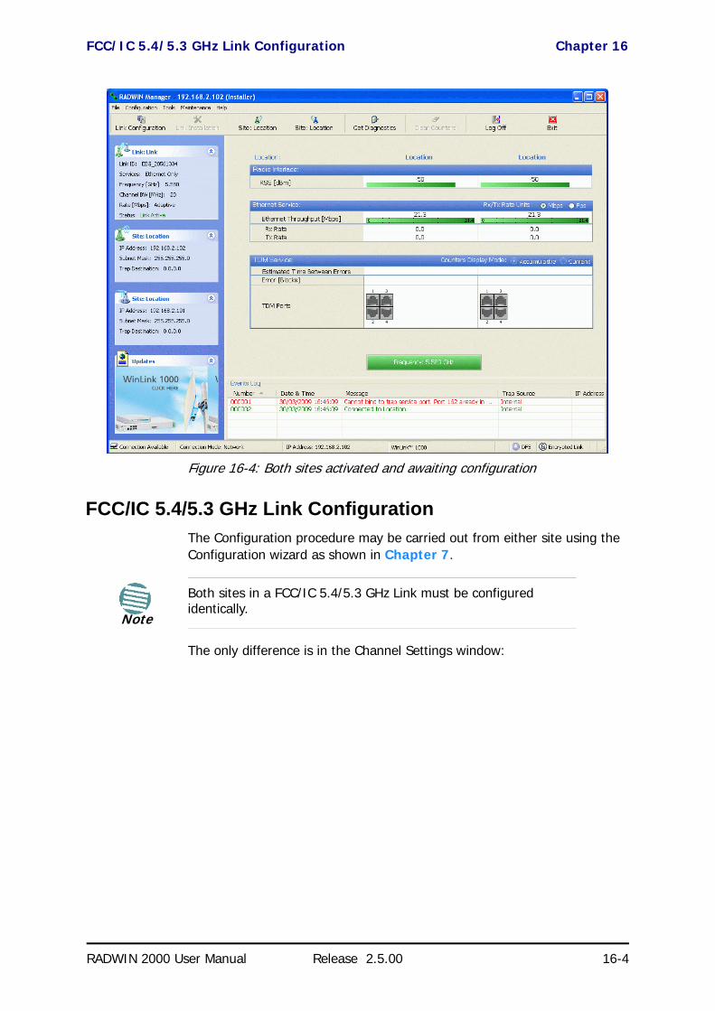
FCC/IC 5.4/5.3 GHz Link Configuration Chapter 16
RADWIN 2000 User Manual Release 2.5.00 16-4
Figure 16-4: Both sites activated and awaiting configuration
FCC/IC 5.4/5.3 GHz Link ConfigurationThe Configuration procedure may be carried out from either site using the Configuration wizard as shown in Chapter 7.
The only difference is in the Channel Settings window:
Note
Both sites in a FCC/IC 5.4/5.3 GHz Link must be configured identically.

FCC/IC 5.4/5.3 GHz Link Configuration Chapter 16
RADWIN 2000 User Manual Release 2.5.00 16-5
Figure 16-5: Channel Select dialog box - ACS permanently enabled
Upon completion of the wizard, the Site configuration dialogs can be used in the usual way. Once operational, the RADWIN Manager window is the same as for other radio equipment models.
Here is the RADWIN Manager main window upon completion of the wizard:
NoteACS cannot be disabled.

FCC/IC 5.4/5.3 GHz Link Configuration Chapter 16
RADWIN 2000 User Manual Release 2.5.00 16-6
Figure 16-6: FCC/IC 5.4/5.3 GHz operational

RADWIN 2000
Broadband Wireless Transmission System
USER MANUAL
RELEASE 2.5.00
Part 4: Field InstallationTopics
UM 2000-2500/09.10

RADWIN 2000 User Manual Release 2.5.00 17-1
Chapter 17
Pole and Wall InstallationODU Mounting Kit Contents
Table 17-1: Bill of Materials: ODU mounting kit
Item Qty
Large Clamp (see Figure 17-1) 1
Small Clamp (see Figure 17-2) 1
Arm (see Figure 17-3) 1
Screw hex head M8x40 4
Screw hex head M8x70 2
Washer flat M8 4
Washer spring M8 3
M8 Nuts 2
Figure 17-1: Large Clamp Figure 17-2: Small Clamp Figure 17-3: Arm
Mounting an ODU on a Pole Chapter 17
RADWIN 2000 User Manual Release 2.5.00 17-2
Mounting an ODU on a Pole
Figure 17-4: Mounting on a pole

Mounting an ODU on a Wall Chapter 17
RADWIN 2000 User Manual Release 2.5.00 17-3
Mounting an ODU on a Wall
Figure 17-5: Mounting on a Wall
Mounting an External AntennaOptional external antennas can be mounted on a pole. The external mount-ing kit varies according to the specific antenna model.

Mounting a Connectorized ODU Horizontally Chapter 17
RADWIN 2000 User Manual Release 2.5.00 17-4
Mounting a Connectorized ODU HorizontallyWhat follows applies to both WinLink 1000 and RADWIN 2000 with obvious differences.
An ODU may be mounted horizontally as shown in Figure 17-6.
To mount an ODU horizontally, observe the following cautions:
1. To ensure your warranty rights for horizontally installed ODUs, make sure that the four ports ANT1, ANT2, HSS and ODU are firmly secured or moisture sealed with the supplied caps.
2. Further, ensure that cables are connected using a “water nose” as shown in Figure 17-6.
Figure 17-6: Mounted ODUs with correct “water nose”
Do not do this:
Figure 17-7: Incorrectly mounted ODU (No “water nose”)
3. If you attach an external PoE device close to the ODU, the same consid-erations apply.

RADWIN 2000 User Manual Release 2.5.00 18-1
Chapter 18
Lightning Protection andGrounding Guidelines
Meticulous implementation of the guidelines in this chapter will provide best protection against electric shock and lightning.
The RADWIN Lightning Protection System consists of the following compo-nents:
• Grounding for the antenna coax cable• Grounding for each IDU and ODU
• External Primary Surge Suppressor units and grounding for the out-door cable
• Internal ESD protection circuits over the Power/Telecom lines
Grounding for Antenna CableA Grounding Kit must be connected to the coax antenna cable and reliably grounded. The grounding kit is an Andrew Type 223158-2 (www.andrew.com). See Figure 18-1 below.
Warning100% protection is neither implied nor possible.
Note
This chapter is at best a guide. The actual degree of lightning protection required depends on local conditions and regulations.

Grounding for Indoor/Outdoor Units Chapter 18
RADWIN 2000 User Manual Release 2.5.00 18-2
Figure 18-1: Grounding antenna cables
Grounding for Indoor/Outdoor Units
ODU GroundingRADWIN Lightning Protection System uses a Shielded CAT-5e cable to inter-connect the Outdoor (ODU) and Indoor (IDU) units.
However, this shielding does not provide a good lightning discharge path, since it can not tolerate the high Lightning Current surges.
To provide an alternate Lightning Discharge path, the ODU and antenna grounding posts should be connected to ground point by a 10 AWG short copper wire.
The device should be permanently connected to ground.
IDU GroundingThe IDU’s grounding post should be connected to the internal ground point, using a grounding wire of at least 10 AWG. The grounding wire should be connected to a grounding rod or the building grounding system.
The device should be permanently connected to ground.

External Lightning Surge Suppressors and Grounding Chapter 18
RADWIN 2000 User Manual Release 2.5.00 18-3
External Lightning Surge Suppressors and GroundingA Grounding Kit and Surge Arrestor Unit must be located near the ODU and properly grounded as illustrated in Figures 18-2 and 18-3 below:
Figure 18-2: Grounding a typical pole installation
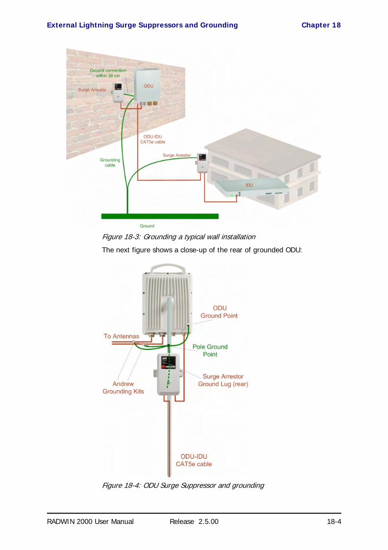
External Lightning Surge Suppressors and Grounding Chapter 18
RADWIN 2000 User Manual Release 2.5.00 18-4
Figure 18-3: Grounding a typical wall installation
The next figure shows a close-up of the rear of grounded ODU:
Figure 18-4: ODU Surge Suppressor and grounding

External Lightning Surge Suppressors and Grounding Chapter 18
RADWIN 2000 User Manual Release 2.5.00 18-5
The Transtector protection circuits shown in Figure 18-5 below, utilize sili-con avalanche diode technology. The unit consists of an outdoor rated NEMA 3R type enclosure with easy mounting flanges, ground stud attach-ment and easy wiring.
The ALPU-POE features RJ-45 protection circuits for the ODU-IDU data pairs (pins 1,2 & 3,6) and DC power (pins 4,5 & 6,7 with the pairs bonded).
The unit is designed to be wall mounted. An optional set of bracket is avail-able to allow a wide range of pole mount applications. A dedicated ground stud is provided inside the unit that must be bonded to the nearest ground-ing system (or Master Ground bar) for proper surge protection.
The system wiring is installed with RJ-45 type connectors that can feed directly into the chassis without having to cut, splice or route through awk-ward strain relief holes.
Figure 18-5: Transtector’s Surge Suppressor
To mount the lightning protection devices:
1. Mount the device as close to the ODU as possible. Mount the unit so that the cable connectors are at the bottom (to prevent water from penetrat-ing), with the strain reliefs facing the ground.
2. Remove the cover by unscrewing the front of the unit.
3. Mount the unit to an outside surface using the two mounting holes.
4. Connect the ODU-IDU cable using the RJ-45 jack.
5. Connect one cable between the ODU and the suppressor using an RJ-45 jack.
6. Connect the suppressor’s ground stud to a grounding point. Use the appropriate wire gauge and type, keeping the wire as short as possible, less than 1m (3’), between the stud and the site grounding point.
External Lightning Surge Suppressors and Grounding Chapter 18
RADWIN 2000 User Manual Release 2.5.00 18-6
7. Replace the cover.
A second Surge Arrestor Unit should be mounted at the building entry point and must be grounded, as shown in Figure 18-3 above.
To mount the lightning protection at the building entry point:
1. Mount the device outside the building, located as near as possible to the entrance of the CAT-5e ODU-IDU cable. Mount the unit so that the cable connectors are at the bottom (to prevent water from penetrating), with the strain reliefs facing the ground.
2. Remove the cover by unscrewing the front of the unit.
3. Mount the unit to an outside surface using the two mounting holes.
4. Connect the ODU-IDU cable using the RJ-45 jack.
5. Connect one cable between the IDU and the suppressor using an RJ-45 jack.
6. Connect the suppressor’s ground stud to a grounding point. Use the appropriate wire gauge and type, keeping the wire as short as possible, less than 1m (3’), between the stud and the site grounding point.
7. Replace the cover
Note
There may also be regulatory requirements to cross bond the ODU-IDU CAT-5e cable at regular intervals up the mast. This may be as frequent as every 10 meters (33 feet).

Internal ESD Protection circuits Chapter 18
RADWIN 2000 User Manual Release 2.5.00 18-7
Figure 18-6: Surge Suppressor and grounding at building entry point
Internal ESD Protection circuitsRADWIN equipment is designed to meet the ETSI/FCC/Aus/NZ/CSA EMC and Safety requirements. To fulfill these requirements, the system's Tele-com lines at the ODU/IDU are Transformer-isolated and include internal ESD (Electro-Static-Discharge) Protection circuits.

RADWIN 2000 User Manual Release 2.5.00 19-1
Chapter 19
Preloading an ODU withan IP Address
Why this is Needed?All ODUs supplied by RADWIN come pre-configured with an IP address of 10.0.0.120. For use in a network, the ODUs must be configured with suit-able static IP addresses. The method for doing this under office conditions is set out in Chapter 5.
There are two situations under which ODUs may need to be pre-loaded with an IP address prior to installation to a link:
• Changing an individual ODU in the field• Preparing a large number of ODUs in a warehouse prior to deploy-
ment in the field, according to a network installation plan.
This chapter explains how do this.
Required EquipmentThe minimal equipment required to pre-load an ODU with an IP address is:
• Laptop computer (managing computer) satisfying the requirements of Table 4-1
• An installed copy of the RADWIN Manager
• A PoE device• A crossed Ethernet LAN cable• An IDU-ODU cable
• If you have connectorized ODUs, two N-type RF terminators
Caution
Do not carry out this procedure using a multi homed managing computer also connected to a network. It will flood the network with broadcast packets. Further, it will throw any other links on the network into Installation mode.

The procedure Chapter 19
RADWIN 2000 User Manual Release 2.5.00 19-2
The procedure
To Preolad an ODU with an IP address:
1. Using the IDU-ODU cable, connect the PoE device to the ODU, ensuring that the cable is plugged into the PoE port marked P-LAN-OUT.
2. For connectorized ODUs, screw the RF terminators into the two antenna ports.
3. Connect the Poe device to AC power.
4. Using a crossed LAN cable, connect the LAN-IN port of the PoE device to the Ethernet port of the managing computer. The ODU will commence beeping at about once per second, indicating correct operation.
5. Launch the RADWIN Manager.
6. At the log on window, choose Local Connection.
Figure 19-1: Log on Window for Local Connection
7. Enter the default password, admin. After a few moments, the RADWIN Manager main window appears:
Note
The following procedure is generic to all RADWIN radio products. What you see on your running RADWIN Manager may differ in some details from the screen captures used to illustrate this chapter.
Warning
A powered up ODU emits RF radiation from the antenna port (or connected antenna). When working with a powered up connectorized ODU, always use RF terminators.
For an ODU with an integrated antenna, ensure that the antenna is always directed away from other people.

The procedure Chapter 19
RADWIN 2000 User Manual Release 2.5.00 19-3
Figure 19-2: Opening RADWIN Manager window prior to installation
8. Click the un-grayed Site:Location button. The following dialog window appears:
Figure 19-3: Configuration Dialog Box
9. Click the Management item in the left hand panel. The following win-dow is presented:

The procedure Chapter 19
RADWIN 2000 User Manual Release 2.5.00 19-4
Figure 19-4: Management Addresses - Site Configuration dialog box
10. Enter the IP Address, Subnet Mask and Default Gateway as requested. For example, the ODU used here is to be configured as follows:
Figure 19-5: ODU with IP Addressing configured
11. Click OK. You are asked to confirm the change:
Figure 19-6: Confirmation of IP Address change

The procedure Chapter 19
RADWIN 2000 User Manual Release 2.5.00 19-5
12. Click Yes to accept the change. After about half a minute the changes will be registered in the ODU. On the left hand panel of the main win-dow, you will see the new IP configuration for the ODU.
Figure 19-7: Main Window after IP Address change
13. Click Cancel to leave the open Management dialog. You may now exit the RADWIN Manager, or connect to another ODU. If you choose to con-nect to another ODU, after about a minute, the main window of the RAD-WIN Manager will revert to that shown in Figure 19-2 above. In any event, power down the changed ODU; your changes will take effect when you power it up again.
Note
Some additional things you may want to do now:
• Go to Site Installation | Air Interface. You can enter a Link ID and change the Installation Frequency and Channel Bandwidth.
• If you log on as Installer, you can change the default band (Chapter 20).
Note
Don’t forget to remove the RF terminators from a connectorized ODU after powering it down.

Tip: How to Recover a Forgotten ODU IP Address Chapter 19
RADWIN 2000 User Manual Release 2.5.00 19-6
Tip: How to Recover a Forgotten ODU IP AddressIf you have an ODU with lost or forgotten IP address, use the above proce-dure to log on to it using Local Connection. The IP address will appear in the left hand status area:
Figure 19-8: Existing IP address displayed after log-on with Local Connec-tion

RADWIN 2000 User Manual Release 2.5.00 20-1
Chapter 20
Changing the FactoryDefault Band
Why this is NeededAll ODUs supplied by RADWIN come with pre-configured with a factory default product-dependent band according to the ODU part number.
For ODUs supporting Multi-band, it may be changed using the procedure in this chapter. The procedure is generic, applying to all ODUs with the Multi-band feature.
Required EquipmentThe minimal equipment required to change an ODU default band is:
• Laptop computer (managing computer) satisfying the requirements of Table 4-1.
• An installed copy of the RADWIN Manager
• A PoE device• A crossed Ethernet LAN cable• An IDU-ODU cable
The procedure
Caution
• If for some reason the default band needs to be changed, it should be done before link installation.
• Use of an incorrect band may be in violation of local regulations.
Note
The following procedure is generic to all relevant RADWIN radio products. What you see on your running RADWIN Manager may differ in some details from the screen captures used to illustrate this chapter.

The procedure Chapter 20
RADWIN 2000 User Manual Release 2.5.00 20-2
To change the factory default band:
1. Using the IDU-ODU cable, connect the PoE device to the ODU, ensuring that the cable is plugged into the PoE port marked P-LAN-OUT.
2. Connect the Poe device to AC power.
3. Using a crossed LAN cable, connect the LAN-IN port of the PoE device to the Ethernet port of the managing computer. The ODU will commence beeping at about once per second, indicating correct operation.
4. Launch the RADWIN Manager.
5. Log on as Installer.
Figure 20-1: Becoming Installer
6. Enter the default password, wireless. After a few moments, the RAD-WIN Manager main window appears:

The procedure Chapter 20
RADWIN 2000 User Manual Release 2.5.00 20-3
Figure 20-2: Opening RADWIN Manager window prior to band change (default circled)
7. Click Tools | Change Band. The following window appears:
Figure 20-3: Change Band dialog
8. Click the band required:
Note
The bands appearing in Figure 20-3 are product dependent. To see which bands are available for your product, check your product Inventory (see Figure 8-8) and then consult RADWIN Customer Support.

The procedure Chapter 20
RADWIN 2000 User Manual Release 2.5.00 20-4
Figure 20-4: A different band selected
9. The Change Band warning is displayed. Click Yes to continue.
Figure 20-5: Change Band confirmation
The change, which may take some time, is carried out:
The result is reflected in the RADWIN Manager main window:

Changing Band for DFS Chapter 20
RADWIN 2000 User Manual Release 2.5.00 20-5
Figure 20-6: Main Window after band change - new band circled
Changing Band for DFSChanging to a DFS band is similar to the foregoing procedure.
As soon as you establish a link using a DFS band, you are offered Configura-tion only in the main menu. Installation mode is disabled.
Special Products or Features: Entering a License KeyIf you go to the Operations window as Installer (Figure 20-7), you will see a provision for entering a license key. Should you ever require such a key, the procedure is as follows:
To enter a License key:
1. Log on as Installer (as for the previous procedure).
2. Click the Site:Location tool bar button from the main tool bar.
Note
If you carry out this operation on a link, the band is effective on both sites and you are placed in installation mode.

Special Products or Features: Entering a License Key Chapter 20
RADWIN 2000 User Manual Release 2.5.00 20-6
Figure 20-7: Using the Operations window to enter a license key
3. Enter your license key and click Activate.
4. When it is accepted, click Cancel.
iiiiiii
Note
License keys, where appropriate, are obtainable from RADWIN Customer Support.

RADWIN 2000 User Manual Release 2.5.00 21-1
Chapter 21
Link Budget CalculatorOverview
The Link Budget Calculator is a utility for calculating the expected perfor-mance of the RADWIN 2000 wireless link and the possible configurations for a specific link range.
The utility allows you to calculate the expected RSS of the link, and find the type of services and their effective throughput as a function of the link range and deployment conditions.
User InputYou are required to enter or choose the following parameters. Depending on the product, some of the parameters have a default value that cannot be changed.
• Band, which determines frequency and regulation• Channel Bandwidth• Tx Power (maximum Tx power per modulation is validated)
• Antenna Type (cannot be changed for ODU with integrated antenna)• Antenna Gain per site (cannot be changed for integrated antenna)• Cable Loss per site (cannot be changed for integrated antenna)
• Required Fade Margin• Rate (and Adaptive check box)• Service Type
• Required Range
Link Budget Calculator Internal DataFor each product (or Regulation and Band) the calculator stores the follow-ing data required for link budget calculations:
• Maximum Transmit power (per modulation)
• Receiver Sensitivity (per modulation) for Ethernet service and for TDM services at various BER
• Maximum linear input power (used to calculate minimum distance)

Calculations Chapter 21
RADWIN 2000 User Manual Release 2.5.00 21-2
• Antenna gain and cable loss for ODU with integrated antenna• Available Channel Bandwidths
Calculations
EIRP
Expected RSS and Fade Margin
where:
Site A is the transmitting site
Site B is the receiving site
PathLoss is calculated according to the free space model,
where Sensitivity is dependent on air-rate.
Min and Max RangeMinRange is the shortest range for which
per air-rate.
MaxRange (with Adaptive checked) is the largest range for which , at the highest air-rate for which this relation-
ship is true. In a link with adaptive rate this will be the actual behavior.
MaxRange (for a given air-rate) is the largest range for which .
ServiceThe Ethernet and configured TDM trunks throughput is calculated according to internal product algorithms.
AvailabilityThe Service Availability calculation is based on the Vigants Barnett method which predicts the downtime probability based on a climate factor (C fac-tor).
EIRP TxPower AntennaGainSiteA CableLossSiteA–+=
ExpectedRSS EIRP PathLoss AntennaGainSiteB CableLossSiteB–+–=
PathLoss 32.45 20 frequencyMHz( ) 20 RequiredRangeKm( )10log×+10log×+=
ExpectedFadeM inarg ExpectedRSS Sensitivity–=
ExpectedRSS MaxInputPower≤
ExpectedRSS Sensitivity≥
ExpectedRSS Sensitivity RequiredFadeM inarg+≥

Antenna Height Chapter 21
RADWIN 2000 User Manual Release 2.5.00 21-3
Antenna HeightThe recommended antenna height required for line of sight is calculated as the sum the Fresnel zone height and the boresight height. See About the Fresnel Zone below. Using the notation of Figure 21-1 below, splitting ExpectedRange into d1 + d2, the Fresnel zone height at distance d1 from the left hand antenna, is given by
For the most conservative setting, we take the mid-point between the
antennas, setting
which gives
simplifying to .
The boresight clearance height is calculated
as:
where .
About the Fresnel ZoneThe Fresnel zone (pronounced "frA-nel", with a silent “s”) is an elliptically shaped conical zone of electromagnetic energy that propagates from the transmitting antenna to the receiving antenna. It is always widest in the middle of the path between the two antennas.
Availability
1 6– 10 7–× Cfactor× frequencyGHz× RequiredRangeKM( )3×
10ExpectedFadeM inarg–
10------------------------------------------------------------
×
=
0.6
300frequencyGHz----------------------------------- d1 d2××
d1 d2+-----------------------------------------------------------×
d1 d2ExpectedRange
2-----------------------------------------= =
0.6
300frequencyGHz----------------------------------- ExpectedRange
2-----------------------------------------
2×
ExpectedRange2
----------------------------------------- ExpectedRange2
-----------------------------------------+--------------------------------------------------------------------------------------------×
0.52 ExpectedRangefrequencyGHz
-----------------------------------------×
R2Mean
ExpectedRange2
-----------------------------------------2
+ RMean–
RMean 6367.4425Km=
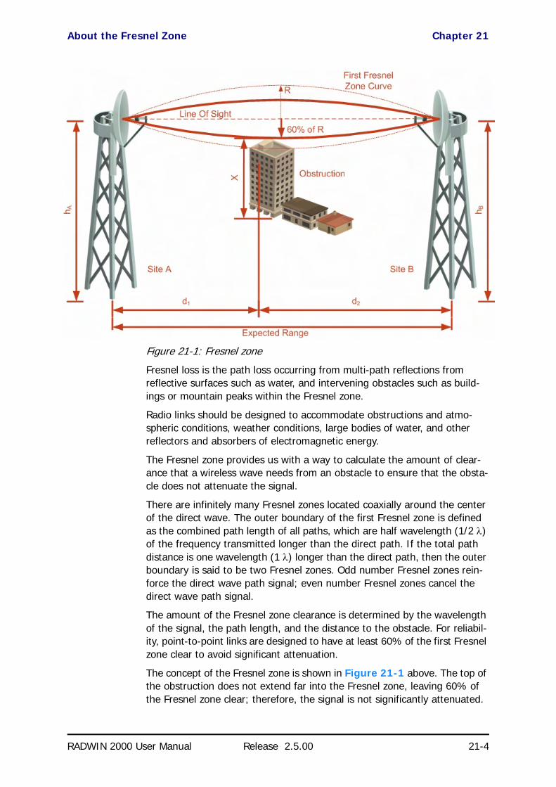
About the Fresnel Zone Chapter 21
RADWIN 2000 User Manual Release 2.5.00 21-4
Figure 21-1: Fresnel zone
Fresnel loss is the path loss occurring from multi-path reflections from reflective surfaces such as water, and intervening obstacles such as build-ings or mountain peaks within the Fresnel zone.
Radio links should be designed to accommodate obstructions and atmo-spheric conditions, weather conditions, large bodies of water, and other reflectors and absorbers of electromagnetic energy.
The Fresnel zone provides us with a way to calculate the amount of clear-ance that a wireless wave needs from an obstacle to ensure that the obsta-cle does not attenuate the signal.
There are infinitely many Fresnel zones located coaxially around the center of the direct wave. The outer boundary of the first Fresnel zone is defined as the combined path length of all paths, which are half wavelength (1/2 λ) of the frequency transmitted longer than the direct path. If the total path distance is one wavelength (1 λ) longer than the direct path, then the outer boundary is said to be two Fresnel zones. Odd number Fresnel zones rein-force the direct wave path signal; even number Fresnel zones cancel the direct wave path signal.
The amount of the Fresnel zone clearance is determined by the wavelength of the signal, the path length, and the distance to the obstacle. For reliabil-ity, point-to-point links are designed to have at least 60% of the first Fresnel zone clear to avoid significant attenuation.
The concept of the Fresnel zone is shown in Figure 21-1 above. The top of the obstruction does not extend far into the Fresnel zone, leaving 60% of the Fresnel zone clear; therefore, the signal is not significantly attenuated.

Running the Link Budget Calculator Chapter 21
RADWIN 2000 User Manual Release 2.5.00 21-5
For more about Fresnel zone, see http://en.wikipedia.org/wiki/Fresnel_zone.
Running the Link Budget CalculatorThe Link Budget Calculator is supplied on the RADWIN Manager CD. It may be run stand-alone from the CD or from the RADWIN Manager application.
To run the Link Budget Calculator from the CD:
1. Insert the RADWIN Manager CD into the drive on the managing com-puter. In the window which opens, click the Link Budget Calculator option.
2. If the CD autorun application does not start by itself, then point your browser to
Z:\RADWIN\Setup\DATA\Link Budget Calculator.htm
where Z should be replaced with your own CD drive name.
To run the Link Budget Calculator from the RADWIN Manager:
• Choose Help | Link Budget Calculator from the main menu of the RADWIN Manager as in the following figure:
Figure 21-2: Accessing the Link Budget Calculator
However invoked, your browser displays the following page:
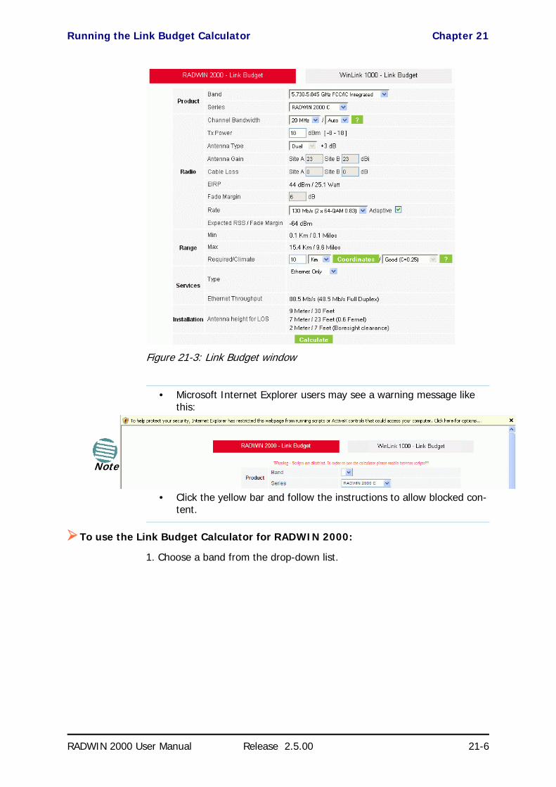
Running the Link Budget Calculator Chapter 21
RADWIN 2000 User Manual Release 2.5.00 21-6
Figure 21-3: Link Budget window
To use the Link Budget Calculator for RADWIN 2000:
1. Choose a band from the drop-down list.
Note
• Microsoft Internet Explorer users may see a warning message like this:
• Click the yellow bar and follow the instructions to allow blocked con-tent.

Running the Link Budget Calculator Chapter 21
RADWIN 2000 User Manual Release 2.5.00 21-7
Figure 21-4: Band selector
2. Chose the relevant RADWIN 2000 series.
Figure 21-5: RADWIN 2000 series selector
3. Choose the Channel Bandwidth.
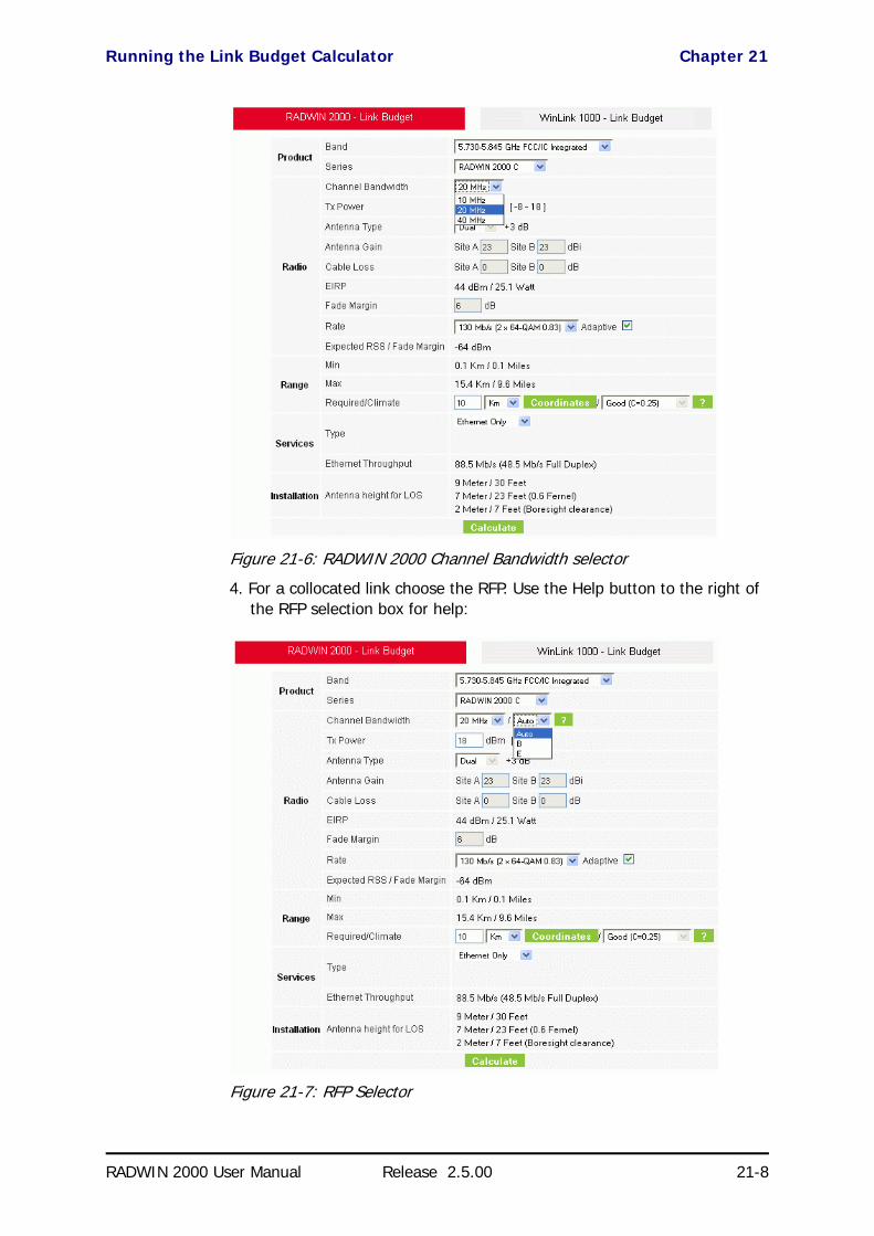
Running the Link Budget Calculator Chapter 21
RADWIN 2000 User Manual Release 2.5.00 21-8
Figure 21-6: RADWIN 2000 Channel Bandwidth selector
4. For a collocated link choose the RFP. Use the Help button to the right of the RFP selection box for help:
Figure 21-7: RFP Selector

Running the Link Budget Calculator Chapter 21
RADWIN 2000 User Manual Release 2.5.00 21-9
Figure 21-8: RFP Selection Guide
For collocated RADWIN 2000 products, you may only use RFP B or E.
5. Enter the radio details. Note that Rate is chosen from a drop-down list:

Running the Link Budget Calculator Chapter 21
RADWIN 2000 User Manual Release 2.5.00 21-10
Figure 21-9: Rate selector
The Rate shown, defines the air-interface rate in Mbps. The system operates in TDD mode and has the overhead of the air-interface pro-toco.l Thus, the Ethernet actual throughput is provided by the Ethernet Rate.
The Fade margin is the minimum required for line-o- sight (LOS) condi-tions. For degraded link conditions, a larger Fade margin should be used.
The EIRP is given in dBm and Watts.
6. If the required range between the two link sites is known, you may enter it directly. Alternatively, you may enter the latitude and longitude of each site in the link, in which case the distance between them will be calcu-lated and displayed.
Note
If you choose Adaptive Rate, then the Rate list is unavailable as is the Climate factor list. Both of these quantities are calculated.
Note
For a given air-rate, Ethernet throughput will decrease with increasing range due to propagation delay.

Running the Link Budget Calculator Chapter 21
RADWIN 2000 User Manual Release 2.5.00 21-11
Figure 21-10: Calculation of distance from site coordinates
For example, if you enter the following coordinates and press Set,
the range will be calculated and displayed:
If for example, we enter:
Site A: 41.1°N lat 74.2°W Long
Site B: 40.8°N lat 74.0°W Long

Running the Link Budget Calculator Chapter 21
RADWIN 2000 User Manual Release 2.5.00 21-12
7. Click Set. The distance and link budget is calculated.
8. Located to the right of the green Coordinates button is a drop-down list of Climactic C Factor values. It is only available if you choose a non-adap-tive rate.
Figure 21-11: Climactic C Factors
For help about what these mean, click the ? button to the right of the list in Figure 21-11.

Running the Link Budget Calculator Chapter 21
RADWIN 2000 User Manual Release 2.5.00 21-13
Figure 21-12: Climactic C Factor description
In Figure 21-13 we display a map of the world showing C Factor con-tours:
Figure 21-13: World map showing C Factor contours

Running the Link Budget Calculator Chapter 21
RADWIN 2000 User Manual Release 2.5.00 21-14
9. Click Calculate to obtain the required performance estimate.
Figure 21-14: LBC - Results section
The Expected Performance parameters are calculated and displayed:
• Expected RSS - the expected RSS that the RADWIN Manager shows when the RADWIN 2000 ODUs are optimally aligned
• Services Type - max number of T1 or E1 trunks if “Max Trunks” is selected
• Ethernet Rate - maximum throughput available for the chosen parameter combination
• Antenna height for LOS – the minimum antenna height required for line-of-sight operation. It is the sum of the height required for boresight clearance due to the earth’s curvature plus the height required to clear the Fresnel zone
If the expected performance is not suitable for your application, try different parameters and repeat the calculation.
Note
Placing the cursor in any other calculated field will also update the calculated results.
RADWIN 2000
Broadband Wireless Transmission System
USER MANUAL
RELEASE 2.5.00
Part 5: Product DependentFeatures
UM 2000-2500/09.10

RADWIN 2000 User Manual Release 2.5.00 22-1
Chapter 22
Spectrum ViewWhat is Spectrum View?
The RADWIN Manager Spectrum View utility is an RF survey tool designed to support the link installation prior to full link service activation. The tool provides comprehensive and clear spectral measurement information enabling easier, faster and better quality installations.
You can view real-time spectrum information, save the spectral information and view retrieved spectral information from historic spectrum scans.
RADWIN’s spectrum measurement and estimation algorithms are designed to show accurate information while accommodating with variations in fre-quency, temperature and interference power while overcoming anomalies that tend to occur in high interference environments.
Running Spectrum View in Installation ModeTo launch Spectrum View, go to the RADWIN Manager main window menu and click Tools | Spectrum View.
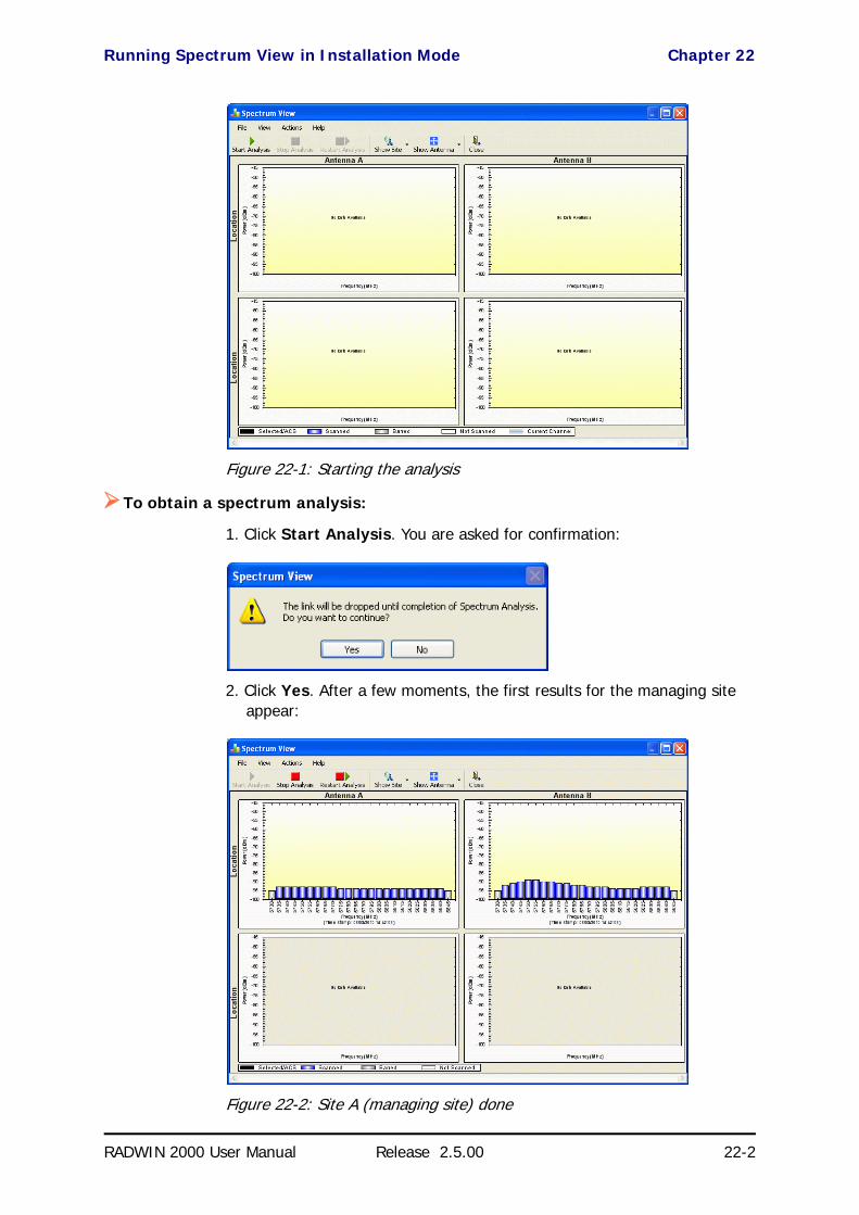
Running Spectrum View in Installation Mode Chapter 22
RADWIN 2000 User Manual Release 2.5.00 22-2
Figure 22-1: Starting the analysis
To obtain a spectrum analysis:
1. Click Start Analysis. You are asked for confirmation:
2. Click Yes. After a few moments, the first results for the managing site appear:
Figure 22-2: Site A (managing site) done

Running Spectrum View in Installation Mode Chapter 22
RADWIN 2000 User Manual Release 2.5.00 22-3
The over-the-air site takes a little longer:
Figure 22-3: Site B (over- the-air site) done, showing current channel
The analysis complete when the Start Analysis button reverts to green. It never runs for longer than ten minutes and you may stop it any time by clicking the red Stop Analysis button.
The results for the over-the-air site are displayed after the link is re-established regardless whether the analysis completes by itself or is stopped.
Current channel
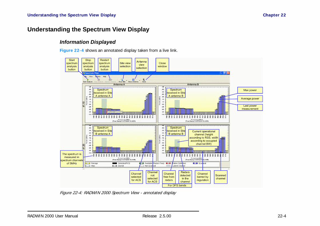
Understanding the Spectrum View Display Chapter 22
RADWIN 2000 User Manual Release 2.5.00 22-4
Understanding the Spectrum View Display
Information DisplayedFigure 22-4 shows an annotated display taken from a live link.
Figure 22-4: RADWIN 2000 Spectrum View - annotated display

Changing the Display Chapter 22
RADWIN 2000 User Manual Release 2.5.00 22-5
From Figure 22-4 above, you can see that the Spectrum View provides clear information including:
• Spectral measurement for each of the 4 receivers that make a RAD-WIN 2000 link (two sites x two antennas per site)
• Spectral power measurements in 5MHz channel granularity• Current, average and maximum power per channel
• Indication of • channels free from radars• channels with radars detected
• barred channels (for DFS bands)• Indication of scanned and un-scanned channels
• Indication of channels selected for ACS• Notation of the current operational channel of the RADWIN 2000 link• Time stamp of the last spectrum scan
• Further, it supports zoom capability, selective view of antennas and sites constituting the link and selectable detail level
Changing the DisplayMoving the mouse anywhere over one the display areas changes it to a cross hair. The mouse may then be used to select an area for zooming, or to enable a right-click System menu.
Figure 22-5: Mouse pointer active for zooming
Selecting a rectangle and clicking will zoom the channels below it to full panel width:
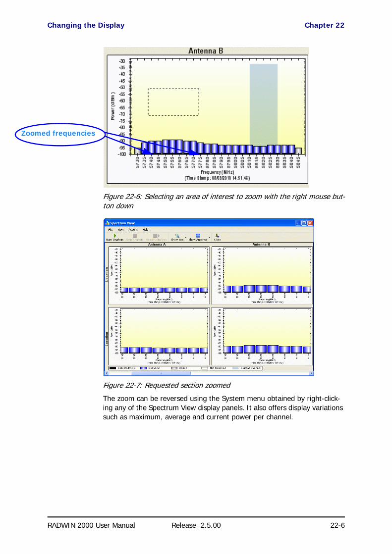
Changing the Display Chapter 22
RADWIN 2000 User Manual Release 2.5.00 22-6
Figure 22-6: Selecting an area of interest to zoom with the right mouse but-ton down
Figure 22-7: Requested section zoomed
The zoom can be reversed using the System menu obtained by right-click-ing any of the Spectrum View display panels. It also offers display variations such as maximum, average and current power per channel.
Zoomed frequencies

Changing the Display Chapter 22
RADWIN 2000 User Manual Release 2.5.00 22-7
Figure 22-8: Spectrum View System menu
Here are two examples:
If you click Show Max, each panel will show the peak values recorded dur-ing the analysis:
Figure 22-9: Effect of setting Show Max
If you click Show Average, each panel will show the average values recorded during the analysis:
Figure 22-10: Effect of setting Show Average
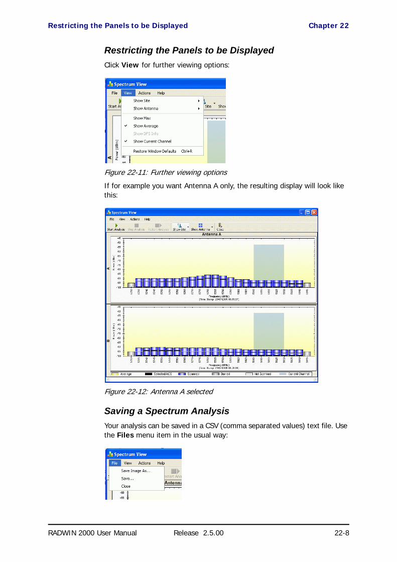
Restricting the Panels to be Displayed Chapter 22
RADWIN 2000 User Manual Release 2.5.00 22-8
Restricting the Panels to be DisplayedClick View for further viewing options:
Figure 22-11: Further viewing options
If for example you want Antenna A only, the resulting display will look like this:
Figure 22-12: Antenna A selected
Saving a Spectrum AnalysisYour analysis can be saved in a CSV (comma separated values) text file. Use the Files menu item in the usual way:

Saving a Spectrum Analysis Chapter 22
RADWIN 2000 User Manual Release 2.5.00 22-9
The Spectrum View information is logged as part of the Diagnostics Information to improve link and system diagnostics and remote support. It can be retrieved from the RADWIN Manager menu using Help |Get Diagnostic Information.
Here is extract of a saved Spectrum View:
Spectrum View - Site: A
Frequencies Scanned,Last Scan Timestamp,Last NF-AntennaA,Last NF-AntennaB,Average NF-AntennaA,Average NF-Anten-naB,Max NF-AntennaA,Max NF-AntennaB
5735,True,30/11/2009 08:20:52,-89,-90,-90,-91,-89,-90,
5740,True,30/11/2009 08:20:52,-89,-90,-90,-91,-89,-90,
5745,True,30/11/2009 08:20:52,-89,-90,-90,-91,-89,-90,
...
5830,True,30/11/2009 08:20:52,-92,-94,-93,-94,-92,-93,
5835,True,30/11/2009 08:20:52,-92,-94,-93,-95,-92,-94,
5840,True,30/11/2009 08:20:52,-92,-94,-93,-95,-92,-94,
Rx Power - AntennaA: -55
Rx Power - AntennaB: -55
Spectrum View - Site: B
Frequency,Is Scanned,Last Scan Timestamp,Last NF-AntennaA,Last NF-AntennaB,Average NF-AntennaA,Average NF-Anten-naB,Max NF-AntennaA,Max NF-AntennaB
5735,True,30/11/2009 08:20:53,-91,-90,-92,-91,-91,-90,
5740,True,30/11/2009 08:20:53,-90,-89,-91,-90,-90,-89,
5745,True,30/11/2009 08:20:53,-90,-89,-91,-90,-90,-89,
...
5830,True,30/11/2009 08:20:53,-93,-94,-94,-94,-93,-93,
5835,True,30/11/2009 08:20:53,-93,-94,-94,-95,-93,-94,
5840,True,30/11/2009 08:20:53,-93,-94,-94,-95,-93,-94,
Rx Power - AntennaA: -57
Rx Power - AntennaB: -55
The column headings are wrapped around. The table values in dBm, are noise-floor (NF) relative.
The CSV file imports easily into most spreadsheet programs. Here is a MS Excel import:
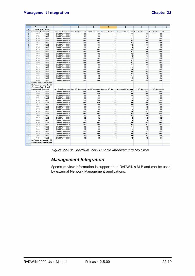
Management Integration Chapter 22
RADWIN 2000 User Manual Release 2.5.00 22-10
Figure 22-13: Spectrum View CSV file imported into MS Excel
Management IntegrationSpectrum view information is supported in RADWIN’s MIB and can be used by external Network Management applications.

RADWIN 2000 User Manual Release 2.5.00 23-1
Chapter 23
Quality of ServiceAvailability
The Quality of Service (QoS) feature is available for links using RADWIN 2000 C radios. If you already have this model, you can access the feature by carrying out a Software Upgrade to the 2.5.00 release.
To use the facility you must be familiar with the use of VLAN (802.1p) or Diffserv.
QoS - OverviewQoS is a technique for prioritization of network traffic packets during con-gestion.
RADWIN 2000 C links support two classification criteria, VLAN based or Diff-serv based. You may chose which of them to use.
Based upon the classification criterion chosen, received packets will be mapped into one of four quality groups: Real time, Near real time, Con-trolled load and Best effort.
Table 23-1: Default priorities an d allocation by VLAN ID and Diffserv
Quality queuePriority
REDAT %Diffserv VLAN
Real time 48-63 6-7 15
Near real time (responsive applications) 32-47 4-5 20
Controlled load 16-31 2-3 25
Best effort 0-15 0-1 40
Note
For REDAT (Remaining Ethernet Data - Ethernet throughput) measurement - see Throughput Checking. REDAT measures remaining Ethernet throughput after reduction of bandwidth used by TDM channels. Use the Link Budget Calculator to see how much remaining bandwidth is available for Ethernet.

Setting up QoS Chapter 23
RADWIN 2000 User Manual Release 2.5.00 23-2
You may partition the total link capacity across the four Quality queues. The default weights as percentages are shown in Table 23-1.
Further, you may also limit the maximum information rate (MIR) for each queue per site.
Setting up QoSYou may set up QoS from either the Installation or Configuration wizards. Before doing so, set up for VLAN (Chapter 14) or Diffserv, depending on which you intend to use.
To define QoS settings for a link:
1. Using either the Installation or Configuration wizards, navigate to the Services window and chose the QoS tab.
Figure 23-1: Services window with QoS selected
Although QoS is a link-oriented feature, each site may have its own sep-arate parameters.
2. Click the Configure button for a site.
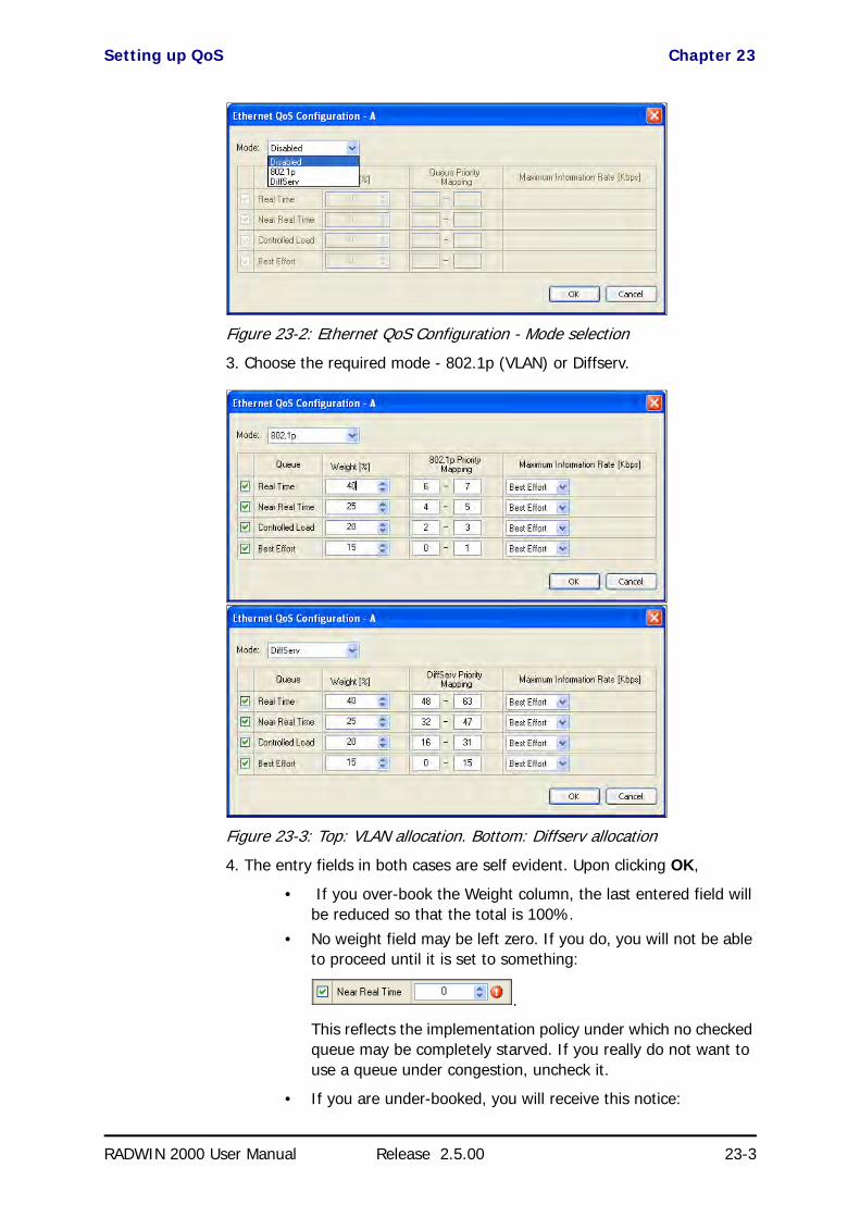
Setting up QoS Chapter 23
RADWIN 2000 User Manual Release 2.5.00 23-3
Figure 23-2: Ethernet QoS Configuration - Mode selection
3. Choose the required mode - 802.1p (VLAN) or Diffserv.
Figure 23-3: Top: VLAN allocation. Bottom: Diffserv allocation
4. The entry fields in both cases are self evident. Upon clicking OK,
• If you over-book the Weight column, the last entered field will be reduced so that the total is 100%.
• No weight field may be left zero. If you do, you will not be able to proceed until it is set to something:
.
This reflects the implementation policy under which no checked queue may be completely starved. If you really do not want to use a queue under congestion, uncheck it.
• If you are under-booked, you will receive this notice:

Disabling QoS Chapter 23
RADWIN 2000 User Manual Release 2.5.00 23-4
• In any event, you may automatically apply the same settings to both link sites:
5. Priorities: You are completely responsible for the completeness and con-sistency of your VLAN or Diffserv priorities.
6. Choose a Maximum Information Rate for each queue:
Figure 23-4: MIR choice - per queue
If you previously used Site | Ethernet | Maximum Information Rate (Chapter 8) to globally limit the site, then your choice in Figure 23-4 will also be limited.l
7. Click OK on the exit dialog to accept the settings. If you did not use these settings for the opposite site, you should configure it now.
8. Complete the wizard in the usual way.
Disabling QoSIn the dialog of Figure 23-2, choose the Disabled mode. The two sites may be enabled or disabled independently.

RADWIN 2000
Broadband Wireless Transmission System
USER MANUAL
RELEASE 2.5.00
Part 6: Product Reference
UM 2000-2500/09.10
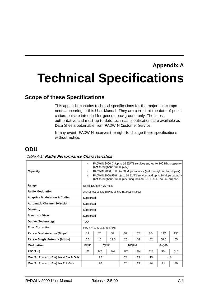
RADWIN 2000 User Manual Release 2.5.00 A-1
Appendix A
Technical SpecificationsScope of these Specifications
This appendix contains technical specifications for the major link compo-nents appearing in this User Manual. They are correct at the date of publi-cation, but are intended for general background only. The latest authoritative and most up to date technical specifications are available as Data Sheets obtainable from RADWIN Customer Service.
In any event, RADWIN reserves the right to change these specifications without notice.
ODUTable A-1: Radio Performance Characteristics
Capacity
• RADWIN 2000 C: Up to 16 E1/T1 services and up to 100 Mbps capacity (net throughput, full duplex)
• RADWIN 2000 L: Up to 50 Mbps capacity (net throughput, full duplex)• RADWIN 2000 PDH: Up to 16 E1/T1 services and up to 10 Mbps capacity
(net throughput, full duplex. Requires an IDU-C or E, no PoE support
Range Up to 120 km / 75 miles
Radio Modulation 2x2 MIMO-OFDM (BPSK/QPSK/16QAM/64QAM)
Adaptive Modulation & Coding Supported
Automatic Channel Selection Supported
Diversity Supported
Spectrum View Supported
Duplex Technology TDD
Error Correction FEC k = 1/2, 2/3, 3/4, 5/6
Rate – Dual Antenna [Mbps] 13 26 39 52 78 104 117 130
Rate – Single Antenna [Mbps] 6.5 13 19.5 26 39 52 58.5 65
Modulation BPSK QPSK 16QAM 64QAM
FEC [k=] 1/2 1/2 3/4 1/2 3/4 2/3 3/4 5/6
Max Tx Power [dBm] for 4.8 – 6 GHz 25 24 21 19 18
Max Tx Power [dBm] for 2.4 GHz 26 25 24 24 21 20

ODU Appendix A
RADWIN 2000 User Manual Release 2.5.00 A-2
(†) For FCC 5.4 and FCC/IC 5.3 bands: To comply with FCC regulations do not select channel bandwidths of 10 and 40 MHz.
Sensitivity (dBm) @BER <10e-11 (20MHz) -88 -86 -83 -81 -77 -72 -70 -67
Encryption AES 128
Table A-2: Supported Frequencies, Regulations and Channel Bandwidths
BandOccupied
Frequency range [GHz]
Compliance Channel Bandwidth
10 MHz 20 MHz 40 MHz
FCC/IC 5.8 5.725 - 5.850 FCC 47CFR, Part 15, Subpart C and IC RSS-210 Yes Yes Yes
FCC 5.4 5.480 - 5.715 FCC 47CFR, Part 15, Subpart E Yes(†) Yes Yes(†)
IC 5.45.480 – 5.5905.660 – 5.715
IC RSS-210 Yes Yes Yes
FCC/IC 5.3 5.260 - 5.340 FCC 47CFR, Part 15, Subpart E and IC RSS-210 Yes(†) Yes Yes(†)
FCC/IC 4.9 4.940 - 4.990 FCC 47CFR, Part 90, Subpart Y and IC RSS-111 Yes Yes No
FCC/IC 2.4 2.402 - 2.472 FCC 47CFR, Part 15, Subpart C and IC RSS-210 Yes Yes No
WPC India 5.8 5.825 – 5.875 GSR-38 Yes Yes Yes
MII China 5.8 5.730 – 5.845 MII China Yes Yes Yes
ETSI 5.8 5.735 – 5.865 ETSI EN 302 502 Yes Yes No
ETSI 5.4 5.480 – 5.715 ETSI EN 301 893 Yes Yes Yes
ETSI 5.3 5.160 – 5.340 ETSI EN 301 893 Yes Yes No
Universal 6.0 5.690– 6.060
N/A
Yes Yes Yes
Universal 5.9 5.730 – 5.960 Yes Yes Yes
Universal 5.4 5.490 – 5.710 Yes Yes Yes
Universal 5.3 5.140 – 5.345 Yes Yes Yes
Universal 4.9 4.890 - 5.010 Yes Yes Yes
Universal 4.8 4.800 - 4.900 Yes Yes Yes
Universal 2.3 2.302 - 2.379 Yes Yes No
Table A-3: Mechanical
ODU with Integrated Antenna 37.1/14.84(W) x 37.1/14.84(H) x 9.00/3.6(D) cm/in; 3.5 kg / 7 lbs
ODU Connectorized 18.0/7.2(W) x 27.0/10.8(H) x 5.5/2.2(D) cm/in; 1.5 kg / 3.0 lbs
Table A-4: Power
Power Feeding Dual feeding, -20 to -60 VDC (AC/DC converter is available)
Power Consumption - alone 25W
Power Consumption with IDU See IDU specifications, this Appendix
Table A-1: Radio Performance Characteristics (Continued)

IDU Appendix A
RADWIN 2000 User Manual Release 2.5.00 A-3
IDUThe following specifications are for most part, common to both IDU-C and new style IDU-E products. Differences are pointed out in the tables.
Table A-5: Configuration
ArchitectureODU: Outdoor Unit with Integrated Antenna or Connectorized for External AntennaIDU: Indoor Unit for service interfaces or PoE device for Ethernet only
ODU to IDU/PoE Interface Outdoor CAT-5e cable; Maximum cable length: 100 m
Table A-6: Management
Management Application (per link) RADWIN Manager
Protocol SNMP and Telnet
NMS RADWIN NMS
Table A-7: Environmental
Operating Temperatures ODU: -35°C to +60°C / -31°F to +140°F
Humidity ODU: Up to 100% non-condensing, IP67
Table A-8: Safety
FCC/IC (cTUVus) UL 60950-1, UL 60950-22, CAN/CSA C22.2 60950-1, CAN/CSA C22.2 60950-22
ETSI/IEC EN/IEC 60950-1, EN/IEC 60950-22
Table A-9: EMC
FCC 47 CFR Class B, Part15, Subpart B
ETSI EN 300 386, EN 301 489-1, EN 301 489-4
CAN/CSA CISPR 22-04 Class B
AS/NZS CISPR 22:2004 Class B
Table A-10: TDM Interface
IDU-C IDU-E
Number of ports 16, 8, 4 ports or no TDM ports. 2 or no TDM port
Max ports usable by WinLink 1000 4 2
Max ports usable by RADWIN 2000 16 2
Type E1/T1 configurable by RADWIN Manager
Framing Unframed (transparent)
Timing Independent timing per port, Tx and Rx
Connector RJ-45
Standards Compliance ITU-T G.703, G.826

IDU Appendix A
RADWIN 2000 User Manual Release 2.5.00 A-4
Line Code E1: HDB3 @ 2.048 Mbps, T1: B8ZS/AMI @ 1.544 Mbps
Latency Configurable 5-20 msec
Impedance E1: 120Ω, balanced, T1: 100Ω, balanced
Jitter & Wander According to ITU-T G.823, G.824
Jitter Buffer Jitter Buffer configuration enabling a latency from 5msec to 16msec for interference immunity confront
Clock Recovery Resolution 0.05ppb
Clock stability 20ppm as clock master (crucial for wander requirements of cellular operators)
Table A-11: LAN Interface
Ethernet ports
Ports: 2
10/100BaseT with Auto-Negotiation (IEEE 802.3u)
Framing/Coding IEEE 802.3
Connector RJ-45
Line Impedance 100 Ω
SFP port (IDU-C only) 1 port, Type: Fast Ethernet
VLAN Support Transparent
Maximum Frame Size 2047 Bytes
Bridge Layer 2, self-learning of up to 2047 MAC addresses (IEEE 802.1Q), hub/Bridge selectable mode
Latency 3 msec
Table A-12: Special Features
Dry Contact Alarms 4 Inputs + 4 Outputs; Configurable by the RADWIN Manager
Monitored Hot Standby (IDU-C only) Supported
Table A-13: Mechanical
IDU-C IDU-E
Style 1U 19” Rack mounted Half 19” wall mounted or desktop
Dimensions 43.6cm(W) x 21cm(D) x 4.4cm(H) 22cm(W) x 17cm(D) x 4.4cm(H)
Weight 1.5 kg/3.3 lbs 0.5 kg/1.1 lbs
Table A-14: Power
IDU-C IDU-E
Power Consumption
With WinLink 1000 ODU < 15W < 15W
With RADWIN 2000 ODU < 35W < 35W
Table A-10: TDM Interface (Continued)
IDU-C IDU-E
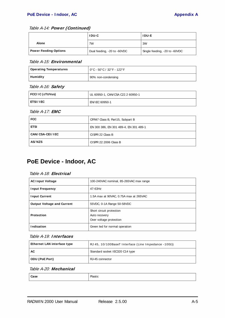
PoE Device - Indoor, AC Appendix A
RADWIN 2000 User Manual Release 2.5.00 A-5
PoE Device - Indoor, AC
Alone 7W 3W
Power Feeding Options Dual feeding, -20 to -60VDC Single feeding, -20 to -60VDC
Table A-15: Environmental
Operating Temperatures 0°C - 50°C / 32°F - 122°F
Humidity 90% non-condensing
Table A-16: Safety
FCC/IC (cTUVus) UL 60950-1, CAN/CSA C22.2 60950-1
ETSI/IEC EN/IEC 60950-1
Table A-17: EMC
FCC CFR47 Class B, Part15, Subpart B
ETSI EN 300 386, EN 301 489-4, EN 301 489-1
CAN/CSA-CEI/IEC CISPR 22 Class B
AS/NZS CISPR 22:2006 Class B
Table A-18: Electrical
AC Input Voltage 100-240VAC nominal, 85-265VAC max range
Input Frequency 47-63Hz
Input Current 1.5A max at 90VAC, 0.75A max at 265VAC
Output Voltage and Current 55VDC, 0-1A Range 50-58VDC
ProtectionShort circuit protectionAuto recoveryOver voltage protection
Indication Green led for normal operation
Table A-19: Interfaces
Ethernet LAN interface type RJ 45, 10/100BaseT Interface (Line Impedance -100Ω)
AC Standard socket IEC320 C14 type
ODU (PoE Port) RJ-45 connector
Table A-20: Mechanical
Case Plastic
Table A-14: Power (Continued)
IDU-C IDU-E

PoE Device - Outdoor, DC Appendix A
RADWIN 2000 User Manual Release 2.5.00 A-6
PoE Device - Outdoor, DC
Dimensions 16cm(W) x 6.3cm(D) x 3.33cm(H)
Weight 250g
Table A-21: Environmental
Operating Temperatures 0°C - 40°C
Humidity 90% non-condensing
Table A-22: Safety
UL 60950
C-UL 60950
TUV/GS IEC/EN 60950
Table A-23: EMC
ESD 61000-4-2
RS 61000-4-3
EFT 61000-4-4
Surge 61000-4-5
CS 61000-4-6
DIPS 61000-4-11
EMI FCC part 15 class B, CISPR Pub 22 class B
Table A-24: Electrical
Input voltage range -20 to -60 VDC (single input)
Output voltage 48VDC / 0.6A
Power Consumption 0.5W (not including radio)
Protections Differential - 15KWCommon – 3KW
Table A-25: Interfaces
Ethernet LAN interface type RJ 45, 10/100BaseT Interface (Line Impedance -100Ω)
DC input 2 pins connector
ODU (PoE Port) RJ45
Table A-26: Mechanical
Dimensions 24.5cm(H) x 13.5cm(W) x 4.0cm(D)
Weight 1.0kg/2.2lbs
Table A-20: Mechanical (Continued)

GSU Appendix A
RADWIN 2000 User Manual Release 2.5.00 A-7
GSU
Table A-27: Environmental
Enclosure All weather cases
Operating Temperatures -35°C - 60°C / -31°F - 140°F
Humidity Up to 100% non-condensing
Standards IEC 60721-3-4 Class 4M5IP67
Table A-28: Safety (Designed to meet these standards)
FCC/IEC/ CAN/CSA 60950-1, 60950-22
Table A-29: EMC (Designed to meet these standards)
ETSI EN 300 386 V1.3.2; EN 301 489-1 V1.4.1
FCC CFR47 Class B, Part15, Subpart B
CAN/CSA ICES-003:2004 Class B
AS/NZS CISPR 22:2006 class B
Table A-30: Configuration
Architecture Outdoor Unit Connectorized for External GPS Antenna
GSU to PoE Interface Outdoor CAT-5e cable; Maximum cable length: 100 m
Table A-31: Mechanical
Dimensions 24.5cm(H) x 13.5cm(W) x 4.0cm(D)
Weight 1.0kg/2.2lbs
Table A-32: Power
Power Feeding Power provided by PoE device
Max Power Dissipation 10Watt
Table A-33: Environmental
Operating Temperature Range -35°C to + 60°C / -13°F to 140°F
Humidity Up to 100% non-condensing
Table A-34: Safety
EN/IEC Designed to meet EN/IEC 60950-1, 60950-22
Table A-35: EMC
FCC Designed to meet 47 CFR Class B, Part15, Subpart B
ETSI Designed to meet EN 300 386 V1.3.3; EN 301 489-4 V1.3.1; EN 301 489-1

Antenna Characteristics Appendix A
RADWIN 2000 User Manual Release 2.5.00 A-8
Antenna CharacteristicsAn antenna is the radiating and receiving element from which the radio sig-nal, in the form of RF power, is radiated to its surroundings and vice versa. The transmission range is a function of the antenna gain and transmitting power. These factors are limited by country regulations.
The RADWIN 2000 may be operated with an integrated antenna attached to the ODU unit, or with an external antenna wired to the ODU via a N-type connectors. All cables and connections must be connected correctly to reduce losses. The required antenna impedance is 50Ω.
CAN/CSA-CEI/IEC Designed to meet CISPR 22-02
AS/NZS Designed to meet CISPR22: 2006 Class B
Table A-35: EMC

RADWIN 2000 User Manual Release 2.5.00 B-1
Appendix B
Wiring SpecificationsODU-IDU Cable
The ODU-IDU cable is shielded/outdoor class CAT-5e, 4 twisted-pair 24 AWG terminated with RJ-45 connectors on both ends. A cable gland on the ODU side provides hermetic sealing.
The following table shows the connector pinout:
ODU/HSS Unit Connection Pinout
Table B-1: ODU-IDU RJ-45 Connector Pinout
Function Color IDU ODU
Ethernet (RxN) White/Green 1 1
Ethernet (RxT) Green 2 2
Ethernet (TxT) White/Orange 3 3
Ethernet (TxN) Orange 6 6
Power (+) Blue 4 4
Power (+) White/Blue 5 5
Power (−) White/Brown 7 7
Power (−) Brown 8 8
Table B-2: ODU/HSS Unit Connection Pinout
Color ODU RJ-45
HSS UNIT RJ-45
White/Green 1 1
GreenNot connected
White/Orange
Orange 6 6
Blue 4 4
White/Blue 5 5

User Port Connectors Appendix B
RADWIN 2000 User Manual Release 2.5.00 B-2
User Port Connectors
LAN PortThe LAN 10/100BaseT interface terminates in an 8-pin RJ-45 connector, wired in accordance to Table B-3.
Trunk Ports - E1/T1 RJ45 ConnectorThe E1/T1 interfaces terminate in 8-pin RJ-45 connectors, as shown in Table B-4 below:
Hot Standby Port RJ-11
White/Brown 7 7
Brown 8 8
Table B-3: Fast Ethernet Connector Pinout
Function Signal Pin
Transmit Data (positive) TD (+) 1
Transmit Data (negative) TD (–) 2
Receive Data (positive) RD (+) 3
Receive Data (negative) RD (–) 6
Table B-4: Trunk Ports - E1/T1 RJ45Pinout
Function Signal Pin
Transmit Data Tip TxTip 1
Transmit Data Ring TxRing 2
Receive Data Tip RxTip 4
Receive Data Ring RxRing 5
Table B-5: Hot Standby RJ-11 Port Pinout
Signal Pin Side A
Pin Side B
HSB out 1 2
HSB in 2 1
Ground 3 3
Ground 4 4
Table B-2: ODU/HSS Unit Connection Pinout (Continued)
Color ODU RJ-45
HSS UNIT RJ-45

IDU (all models) Alarm Connector Appendix B
RADWIN 2000 User Manual Release 2.5.00 B-3
IDU (all models) Alarm ConnectorThe IDU Alarm interface is a 25 pin D type female connector. Its pinout is listed in Table B-6.
The figure below, shows how to connect external input and output alarms.
Table B-6: IDU Alarm Connector (Dry-Contact)
I/O Description Pin
Input 1 Positive 14
Input 1 Negative 15
Input 2 Positive 16
Input 2 Negative 17
Input 3 Positive 18
Input 3 Negative 19
Input 4 Positive 20
Input 4 Negative 21
Output 1 Normally Open 1
Output 1 Common 2
Output 1 Normally Closed 3
Output 2 Normally Open 4
Output 2 Common 5
Output 2 Normally Closed 6
Output 3 Normally Open 7
Output 3 Common 8
Output 3 Normally Closed 9
Output 4 Normally Open 10
Output 4 Common 11
Output 4 Normally Closed 12
Note
• Use an external current limit resistor to limit the current at the output relays to 1 Amp. Such resistor is not required if the equipment con-nected to the IDU supports current limiting to 1 Amp.
• The voltage of the input alarm must be within the range of -10 to -50 VDC.
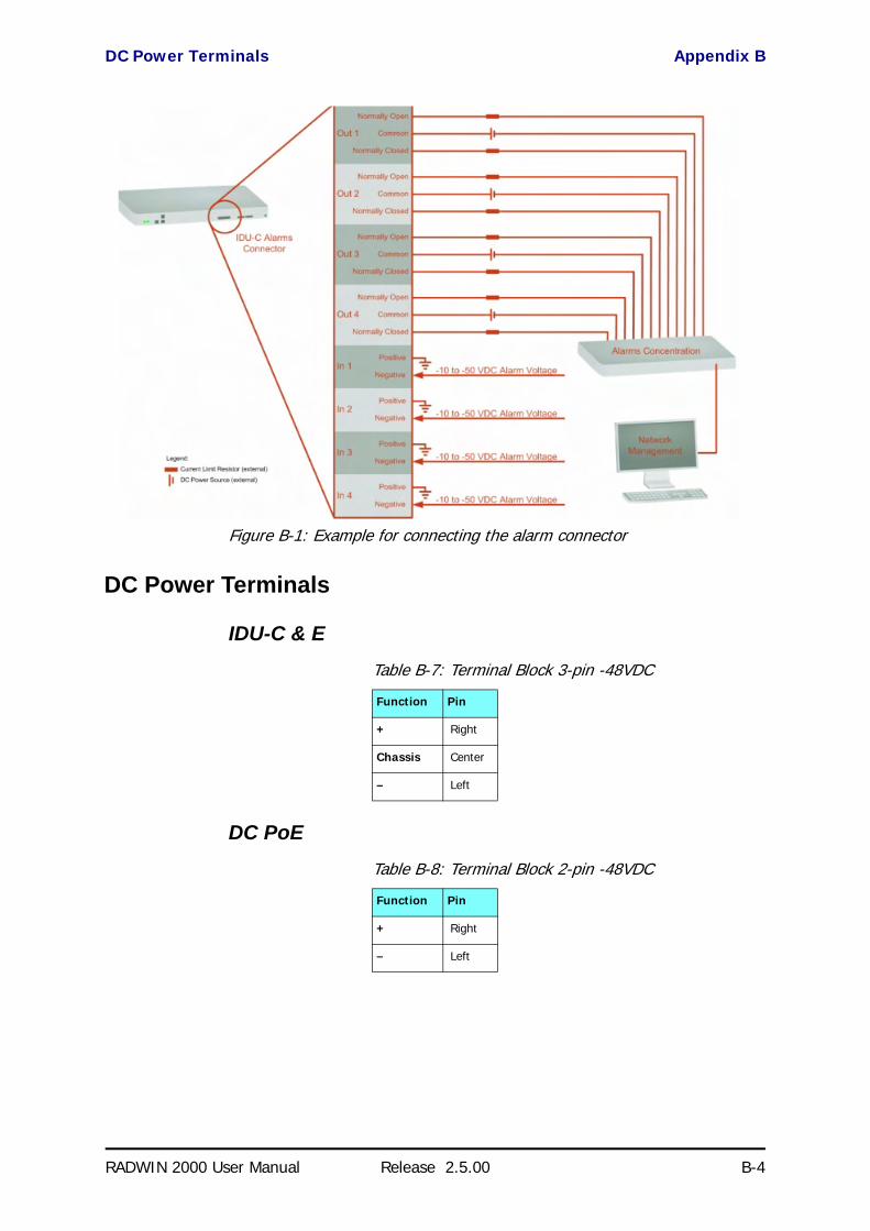
DC Power Terminals Appendix B
RADWIN 2000 User Manual Release 2.5.00 B-4
Figure B-1: Example for connecting the alarm connector
DC Power Terminals
IDU-C & E
DC PoE
Table B-7: Terminal Block 3-pin -48VDC
Function Pin
+ Right
Chassis Center
– Left
Table B-8: Terminal Block 2-pin -48VDC
Function Pin
+ Right
– Left

RADWIN 2000 User Manual Release 2.5.00 C-1
Appendix C
Small Form-factorPluggable Transceiver
IDU-C SFP SupportThe Small Form-factor Pluggable (SFP) transceiver, is a compact, hot-plug-gable transceiver used in communications applications.
The SFP transceiver technology allows almost any protocol converter imple-mentation with seamless integration to a standard Ethernet switch.
The IDU-C supports SFP transceivers to provide and support several net-work applications.
Any standard Fast Ethernet (FE) SFP transceiver can be plugged into the IDU-C. These SFPs support various Ethernet interfaces. For example a fibre optic interface can be used to support long fibre distances.
In addition, System on SFP transceivers can be used, supporting a proto-col converter concept. The main application for such SFP transceivers is TDM over Ethernet providing E1/T1 or E3/T3 over full duplex Ethernet Remote Bridge
The following table provides a few SFP types that can be used with the IDU-C:
Table C-1: SFP Type and Interface description
SFP Type Interface Description
100baseT 100BaseT, IEEE 802.3, UTP CAT5
100baseFX Multimode fiber-optic (MMF) link spans up to 2km long
100baseLX Single-mode fiber optic (SMF) links pans up to 10km
100baseBX SMF single-strand link spans up to 10 km or 40 km
E3T3/FE E3/T3

RADWIN 2000 User Manual Release 2.5.00 D-1
Appendix D
MIB ReferenceIntroduction
About the MIBThe RADWIN MIB is a set of APIs that enables external applications to con-trol RADWIN equipment.
The MIB is divided into public and a private API groups:
• Public: RFC-1213 (MIB II) variables, RFC-1214 (MIB II) System and Interfaces sections
• Private: Controlled by RADWIN and supplements the public group.
This appendix describes the public and private MIB used by RADWIN.
TerminologyThe following terms are used in this appendix.
In addition, the MIB uses internally, the older notions of Local site and Remote site where this manual would use site A and site B.
To avoid burdening the reader, this appendix will follow the MIB usage.
Interface API
Control MethodThe RADWIN Manager application provides all the means to configure and monitor a RADWIN 2000 link, communicating with the SNMP agent in each ODU. Each SNMP agent contains data on each of the IDUs and ODUs in the
Term Meaning
MIB Management Information Base
API Application Programming Interface
SNMP Simple Network Management Protocol
Community String Appendix D
RADWIN 2000 User Manual Release 2.5.00 D-2
link. Both agents communicate with each other over the air using a proprie-tary protocol.
To control and configure the device using the MIB, you should adhere to the following rules:
• The connection for control and configuration is to the local site, over any SNMP/UDP/IP network.
• All Parameters should be consistent between both of the ODUs. Note that inconsistency of air parameters can break the air connection. To correct air parameters inconsistency you must reconfigure each of the ODUs.
• Common practice is to configure the remote site first and then to configure the local site.
• For some of the configuration parameters additional action must be taken before the new value is loaded. Please refer to the operation in the parameters description.
• Some of the MIB parameters values are product dependent. It is strongly recommend using the RADWIN Manager Application for changing these values. Setting wrong values may cause indetermi-nate results.
Community StringTo control a link, all SNMP requests should go to the local site IP address.
See Table 4-4 for default Community strings.
Private MIB StructureThe sections in the private RADWIN MIB and its location in the MIB tree are shown in Figure D-1 below:
NoteEach ODU has a single MAC address and a single IP address.
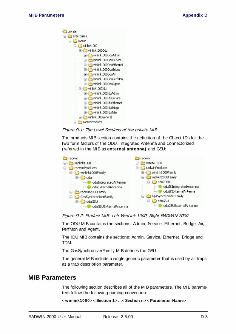
MIB Parameters Appendix D
RADWIN 2000 User Manual Release 2.5.00 D-3
Figure D-1: Top Level Sections of the private MIB
The products MIB section contains the definition of the Object IDs for the two form factors of the ODU, Integrated Antenna and Connectorized (referred in the MIB as external antenna) and GSU:
Figure D-2: Product MIB: Left WinLink 1000, Right RADWIN 2000
The ODU MIB contains the sections: Admin, Service, Ethernet, Bridge, Air, PerfMon and Agent.
The IDU MIB contains the sections: Admin, Service, Ethernet, Bridge and TDM.
The GpsSynchronizerFamily MIB defines the GSU.
The general MIB include a single generic parameter that is used by all traps as a trap description parameter.
MIB ParametersThe following section describes all of the MIB parameters. The MIB parame-ters follow the following naming convention:
<winlink1000><Section 1>...<Section n><Parameter Name>

Supported Variables from the RFC 1213 MIB Appendix D
RADWIN 2000 User Manual Release 2.5.00 D-4
For each of the configuration and control parameters (parameters with read-write access), the “Description” column describes when the new value is effective. It is recommended that you perform the appropriate action to make the values affective immediately after any change. Where a change is required on both sides of the link, it is recommended that you change both sides of the link first and then perform the action.
Supported Variables from the RFC 1213 MIB
Table D-1: Supported RFC 1213 Variables (Sheet 1 of 2)Name OID Type
Access
Description
ifIndex .1.3.6.1.2.1.2.2.1.1.xa Integer RO A unique value for each interface.Its value ranges between 1 and the value of ifNumber.The value for each interface must remain constant at least from one re-initialization of the entity's network management system to the next re-initialization.
ifDescr .1.3.6.1.2.1.2.2.1.2 DisplayString RO A textual string containing information about the interface.This string should include the name of the manufacturer, the product name and the version of the hardware interface.
ifType .1.3.6.1.2.1.2.2.1.3 Integer RO The type of interface, distinguished according to the physical/link protocol(s) immediately `below' the network layer in the protocol stack.
ifSpeed .1.3.6.1.2.1.2.2.1.5 Gauge RO An estimate of the interface's current bandwidth in bits per second.For interfaces which do not vary in bandwidth or for those where no accurate estimation can be made, this object should ontain the nominal bandwidth.
ifPhysAddress .1.3.6.1.2.1.2.2.1.6 Phys-Address RO The interface's address at the protocol layer immediately `below' the network layer in the protocol stack. For interfaces which do not have such an address (e.g., a serial line), this object should contain an octet string of zero length.
ifAdminStatus .1.3.6.1.2.1.2.2.1.7 Integer RW The desired state of the interface. The testing(3) state indicates that no operational packets can be passed.
ifOperStatus .1.3.6.1.2.1.2.2.1.8 Integer RO The current operational state of the interface. The testing(3) state indicates that no operational packets can be passed.
ifInOctets .1.3.6.1.2.1.2.2.1.10.x Counter RO The total number of octets received on the interface, including framing characters.
ifInUcastPkts .1.3.6.1.2.1.2.2.1.11.x Counter RO The number of subnetwork-unicast packets delivered to a higher-layer protocol.
ifInNUcastPkts .1.3.6.1.2.1.2.2.1.12.x Counter RO The number of non-unicast (i.e., subnetwork- broadcast or subnetwork-multicast) packets delivered to a higher-layer protocol.
ifInErrors .1.3.6.1.2.1.2.2.1.14.x Counter RO The number of inbound packets that contained errors preventing them from being deliverable to a higher-layer protocol.
ifOutOctets .1.3.6.1.2.1.2.2.1.16.x Counter RO The total number of octets transmitted out of the interface, including framing characters.
ifOutUcastPkts .1.3.6.1.2.1.2.2.1.17.x Counter RO The total number of packets that higher-level protocols requested be transmitted to a subnetwork-unicast address, including those that were discarded or not sent.

Supported Variables from the RFC 1213 MIB Appendix D
RADWIN 2000 User Manual Release 2.5.00 D-5
ifOutNUcastPkts .1.3.6.1.2.1.2.2.1.18.x Counter RO The total number of packets that higher-level protocols requested be transmitted to a non- unicast (i.e., a subnetwork-broadcast or subnetwork-multicast) address, including those that were discarded or not sent.
a. x is the interface ID
Table D-1: Supported RFC 1213 Variables (Sheet 2 of 2)Name OID Type
Access
Description

MIB Parameters Appendix D
RADWIN 2000 User Manual Release 2.5.00 D-6
MIB ParametersTable D-2: Private MIB Parameters (Sheet 1 of 17)Name OID Type
Access
Description
winlink1000OduAdmProductType 1.3.6.1.4.1.4458.1000.1.1.1 DisplayString RO ODU configuration description.
winlink1000OduAdmHwRev 1.3.6.1.4.1.4458.1000.1.1.2 DisplayString RO ODU Hardware Version.
winlink1000OduAdmSwRev 1.3.6.1.4.1.4458.1000.1.1.3 DisplayString RO ODU Software Version.
winlink1000OduAdmLinkName 1.3.6.1.4.1.4458.1000.1.1.4 DisplayString RW Link Name. A change is effective immediately.
winlink1000OduAdmResetCmd 1.3.6.1.4.1.4458.1000.1.1.5 Integer RW Reset Command. A set command with a value of 3 will cause a device reset. The read value is always 0.
winlink1000OduAdmAddres 1.3.6.1.4.1.4458.1000.1.1.6 IpAddress RW ODU IP address. A change is effective after reset. The parameter is kept for backward compatibility. Using the alternative parameter: winlink1000OduAdmIpParamsCnfg is recommended.
winlink1000OduAdmMask 1.3.6.1.4.1.4458.1000.1.1.7 IpAddress RW ODU Subnet Mask. A change is effective after reset. The parameter is kept for backward compatibility. Using the alternative parameter: winlink1000OduAdmIpParamsCnfg is recommended.
winlink1000OduAdmGateway 1.3.6.1.4.1.4458.1000.1.1.8 IpAddress RW ODU default gateway. A change is effective after reset. The parameter is kept for backward compatibility. Using the alternative parameter: winlink1000OduAdmIpParamsCnfg is recommended.
winlink1000OduAdmBroadcast 1.3.6.1.4.1.4458.1000.1.1.10 Integer RW This parameter is reserved for the Manager application provided with the product.
winlink1000OduAdmHostsTable N/A Trap destinations table. Each trap destination is defined by an IP address and a UDP port. Up to 10 addresses can be configured.
winlink1000OduAdmHostsEntry N/A Trap destinations table entry. INDEX winlink1000OduAdmHostsIndex
winlink1000OduAdmHostsIndex RO Trap destinations table index.
winlink1000OduAdmHostsIp 1.3.6.1.4.1.4458.1000.1.1.12.1.2 IpAddress RW Trap destination IP address. A change is effective immediately.
winlink1000OduAdmHostsPort 1.3.6.1.4.1.4458.1000.1.1.12.1.3 Integer RW UDP port of the trap destination. A change is effective immediately.
winlink1000OduBuzzerAdminState 1.3.6.1.4.1.4458.1000.1.1.13 Integer RW This parameter controls the activation of the buzzer while the unit is in install mode. A change is effective immediately. The valid values are: disabled (0) enabledAuto (1) enabledConstantly(2).
winlink1000OduProductId 1.3.6.1.4.1.4458.1000.1.1.14 DisplayString RO This parameter is reserved for the Manager application provided with the product.
winlink1000OduReadCommunity 1.3.6.1.4.1.4458.1000.1.1.15 DisplayString RW Read Community String. This parameter always returns ***** when retrieving its value. It is used by the Manager application to change the Read Community String. The SNMP agent accepts only encrypted values.
winlink1000OduReadWriteCommunity 1.3.6.1.4.1.4458.1000.1.1.16 DisplayString RW Read/Write Community String. This parameter always returns ***** when retrieving its value. It is used by the Manager application to change the Read/Write Community String. The SNMP agent accepts only encrypted values.
winlink1000OduTrapCommunity 1.3.6.1.4.1.4458.1000.1.1.17 DisplayString RW Trap Community String. This parameter is used by the Manager application to change the Trap Community String. The SNMP agent accepts only encrypted values.

MIB Parameters Appendix D
RADWIN 2000 User Manual Release 2.5.00 D-7
winlink1000OduAdmSnmpAgentVersion 1.3.6.1.4.1.4458.1000.1.1.18 Integer RO Major version of the SNMP agent.
winlink1000OduAdmRemoteSiteName 1.3.6.1.4.1.4458.1000.1.1.19 DisplayString RO Remote site name. Returns the same value as sysLocation parameter of the remote site.
winlink1000OduAdmSnmpAgentMinorVersion 1.3.6.1.4.1.4458.1000.1.1.20 Integer RO Minor version of the SNMP agent.
winlink1000OduAdmLinkPassword 1.3.6.1.4.1.4458.1000.1.1.21 DisplayString RW Link Password. This parameter always returns ***** when retrieving its value. It is used by the Manager application to change the Link Password. The SNMP agent accepts only encrypted values.
winlink1000OduAdmSiteLinkPassword 1.3.6.1.4.1.4458.1000.1.1.22 DisplayString RW Site Link Password. This parameter always returns ***** when retrieving its value. It is used by the Manager application to change the Link Password of the site. The SNMP agent accepts only encrypted values.
winlink1000OduAdmDefaultPassword 1.3.6.1.4.1.4458.1000.1.1.23 Integer RO This parameter indicates if the current Link Password is the default password.
winlink1000OduAdmConnectionType 1.3.6.1.4.1.4458.1000.1.1.24 Integer RO This parameter indicates if the Manager application is connected to the local ODU or to the remote ODU over the air. A value of 'unknown' indicates community string mismatch.
winlink1000OduAdmBackToFactorySettingsCmd
1.3.6.1.4.1.4458.1000.1.1.25 Integer RW Back to factory settings Command. A change is effective after reset. The read value is always 0.
winlink1000OduAdmIpParamsCnfg 1.3.6.1.4.1.4458.1000.1.1.26 DisplayString RW ODU IP address Configuration. The format is: <IP_Address>|<Subnet_Mask>|<Default_Gateway>|
winlink1000OduAdmVlanID 1.3.6.1.4.1.4458.1000.1.1.27 Integer RW VLAN ID. Valid values are 1 to 4094. Initial value is 0 meaning VLAN unaware.
winlink1000OduAdmVlanPriority 1.3.6.1.4.1.4458.1000.1.1.28 Integer RW VLAN Priority. 0 is lowest priority 7 is highest priority.
winlink1000OduAdmSN 1.3.6.1.4.1.4458.1000.1.1.29 DisplayString RO ODU Serial Number
winlink1000OduAdmProductName 1.3.6.1.4.1.4458.1000.1.1.30 DisplayString RO This is the product name as it exists at EC
winlink1000OduAdmActivationKey 1.3.6.1.4.1.4458.1000.1.1.31 DisplayString RW Activates a general key.
winlink1000OduAdmRmtPermittedOduType 1.3.6.1.4.1.4458.1000.1.1.32 DisplayString RW Mobile Application: permitted partner OduType.
winlink1000OduAdmCpuID 1.3.6.1.4.1.4458.1000.1.1.33 Integer RO CPU ID
winlink1000OduSrvMode 1.3.6.1.4.1.4458.1000.1.2.1 Integer RW System mode. The only values that can be set are installMode and slaveMode; normalMode reserved to the Manager application provided with the product. A change is effective after link re-synchronization.
winlink1000OduSrvBridging 1.3.6.1.4.1.4458.1000.1.2.3 Integer RO Bridging Mode. Valid values are: disabled (0) enabled (1).
winlink1000OduSrvRingLinkMode 1.3.6.1.4.1.4458.1000.1.2.4.1 Integer RW Mode of the link regarding ring topology.
winlink1000OduSrvRingTopologySupported 1.3.6.1.4.1.4458.1000.1.2.4.2 Integer RO Ring Topology options are: supported not supported
winlink1000OduSrvRingVlanIdTable N/A Ring VLAN IDs table.
winlink1000OduSrvRingVlanIdEntry N/A VLAN ID of the internal ring messages. Valid values are 1 to 4094. Initial value is 0 meaning VLAN unaware. INDEX winlink1000OduSrvRingVlanIdIndex
winlink1000OduSrvRingVlanIdIndex 1.3.6.1.4.1.4458.1000.1.2.4.3.1.1 Integer RO Index of VLAN ID of the internal ring messages.
winlink1000OduSrvRingVlanId 1.3.6.1.4.1.4458.1000.1.2.4.3.1.2 Integer RW VLAN ID of the internal ring messages. Valid values are 1 to 4094. Initial value is 0 meaning VLAN unaware.
winlink1000OduSrvRingEthStatus 1.3.6.1.4.1.4458.1000.1.2.4.4 Integer RO Represents the Ethernet service blocking state of a Rings link
Table D-2: Private MIB Parameters (Sheet 2 of 17)Name OID Type
Access
Description

MIB Parameters Appendix D
RADWIN 2000 User Manual Release 2.5.00 D-8
winlink1000OduSrvRingMaxAllowedTimeFromLastRpm
1.3.6.1.4.1.4458.1000.1.2.4.5 Integer RW Defines the minimal time (in ms) required for determination of ring failure.
winlink1000OduSrvRingWTR 1.3.6.1.4.1.4458.1000.1.2.4.6 Integer RW Defines the minimal time (in ms) required for ring recovery.
winlink1000OduSrvQoSMode 1.3.6.1.4.1.4458.1000.1.2.5.1 Integer RW Mode of QoS feature.
winlink1000OduSrvQoSConfTable N/A QoS configuration table.
winlink1000OduSrvQoSConfEntry N/A QoS configuration table. INDEX winlink1000OduSrvQoSConfIndex
winlink1000OduSrvQoSConfIndex 1.3.6.1.4.1.4458.1000.1.2.5.2.1.1 Integer RO Index of QoS Configuration.
winlink1000OduSrvConfVlanQGroups 1.3.6.1.4.1.4458.1000.1.2.5.2.1.2 Integer RO Frames classification according to VLAN Priority IDs.
winlink1000OduSrvConfDiffservQGroups 1.3.6.1.4.1.4458.1000.1.2.5.2.1.3 Integer RO Frames classification according to Diffserv.
winlink1000OduSrvConfQueMir 1.3.6.1.4.1.4458.1000.1.2.5.2.1.4 Integer RW Desired Private MIR.
winlink1000OduSrvConfQueWeight 1.3.6.1.4.1.4458.1000.1.2.5.2.1.5 Integer RW QoS queueu's weights in percent.
winlink1000OduSrvQoSVlanQGroupsSetStr 1.3.6.1.4.1.4458.1000.1.2.5.3 DisplayString RW Frames classification according to VLAN IDs string for set.
winlink1000OduSrvQoSDiffservQGroupsSetStr 1.3.6.1.4.1.4458.1000.1.2.5.4 DisplayString RW Frames classification according to Diffserv IDs string for set.
winlink1000OduSrvQoSMaxRTQuePercent 1.3.6.1.4.1.4458.1000.1.2.5.5 Integer RO Maximal percent for RT & NRT queues.
winlink1000OduEthernetRemainingRate 1.3.6.1.4.1.4458.1000.1.3.1 Integer RO Current Ethernet bandwidth in bps.
winlink1000OduEthernetIfTable N/A ODU Ethernet Interface table.
winlink1000OduEthernetIfEntry N/A ODU Ethernet Interface table entry. INDEX winlink1000OduEthernetIfIndex
winlink1000OduEthernetIfIndex 1.3.6.1.4.1.4458.1000.1.3.2.1.1 Integer RO ODU Ethernet Interface Index.
winlink1000OduEthernetIfAddress 1.3.6.1.4.1.4458.1000.1.3.2.1.5 DisplayString RO ODU MAC address.
winlink1000OduEthernetIfAdminStatus 1.3.6.1.4.1.4458.1000.1.3.2.1.6 Integer RW Required state of the interface.
winlink1000OduEthernetIfOperStatus 1.3.6.1.4.1.4458.1000.1.3.2.1.7 Integer RO Current operational state of the interface.
winlink1000OduEthernetIfFailAction 1.3.6.1.4.1.4458.1000.1.3.2.1.8 Integer RW Failure action of the interface.
winlink1000OduEthernetNumOfPorts 1.3.6.1.4.1.4458.1000.1.3.3 Integer RO Number of ODU network interfaces.
winlink1000OduBridgeBasePortTable N/A ODU Bridge Ports table.
winlink1000OduBridgeBasePortEntry N/A ODU Bridge Ports table entry. INDEX winlink1000OduBridgeBasePortIndex
winlink1000OduBridgeBasePortIndex RO ODU Bridge Port Number.
winlink1000OduBridgeBaseIfIndex RO IfIndex corresponding to ODU Bridge port.
winlink1000OduBridgeTpMode 1.3.6.1.4.1.4458.1000.1.4.4.101 Integer RW ODU bridge mode. A change is effective after reset. Valid values: hubMode (0) bridgeMode (1).
winlink1000OduBridgeTpPortTable N/A ODU Transparent Bridge Ports table.
winlink1000OduBridgeTpPortEntry N/A ODU Transparent Bridge Ports table entry. INDEX winlink1000OduBridgeTpPortIndex
winlink1000OduBridgeTpPortIndex RO ODU Transparent Bridge Port Number.
winlink1000OduBridgeTpPortInFrames 1.3.6.1.4.1.4458.1000.1.4.4.3.1.3 Counter RO Number of frames received by this port.
winlink1000OduBridgeTpPortOutFrames 1.3.6.1.4.1.4458.1000.1.4.4.3.1.4 Counter RO Number of frames transmitted by this port.
winlink1000OduBridgeTpPortInBytes 1.3.6.1.4.1.4458.1000.1.4.4.3.1.101
Counter RO Number of bytes received by this port.
winlink1000OduBridgeTpPortOutBytes 1.3.6.1.4.1.4458.1000.1.4.4.3.1.102
Counter RO Number of bytes transmitted by this port.
winlink1000OduBridgeConfigMode 1.3.6.1.4.1.4458.1000.1.4.4.102 Integer RO ODU bridge configuration mode
winlink1000OduAirFreq 1.3.6.1.4.1.4458.1000.1.5.1 Integer RW Installation Center Frequency. Valid values are product dependent. A change is effective after link re-synchronization.
Table D-2: Private MIB Parameters (Sheet 3 of 17)Name OID Type
Access
Description
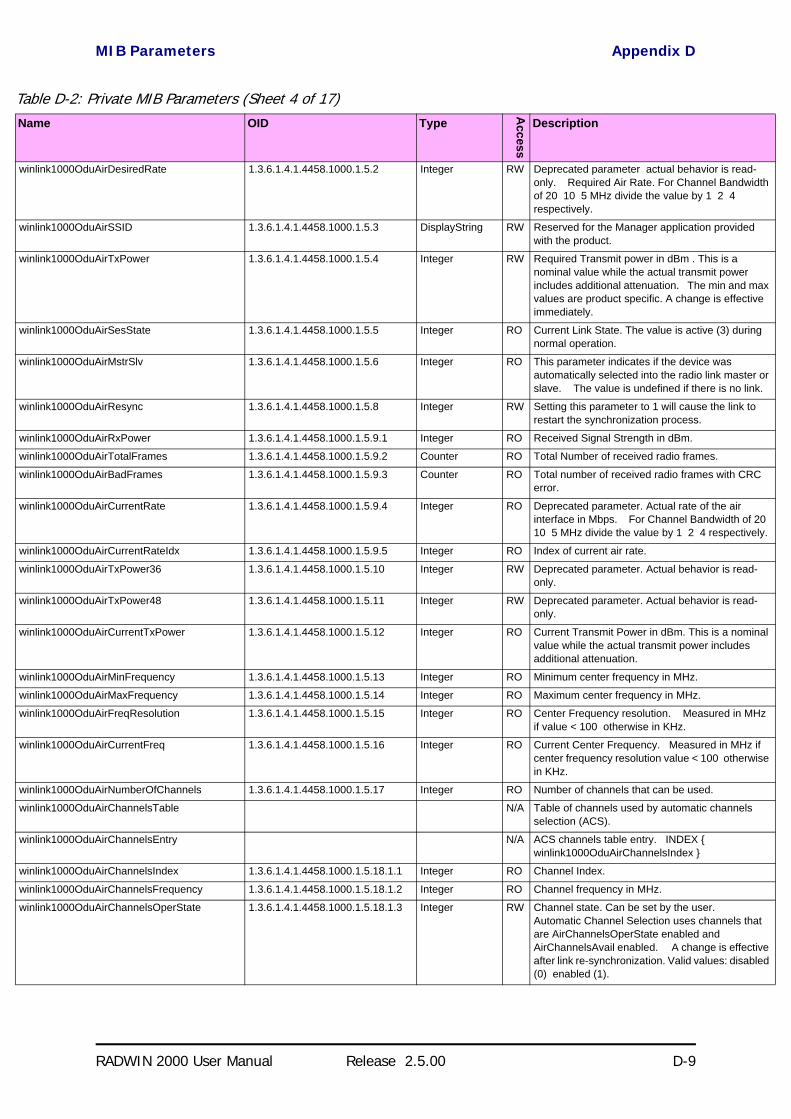
MIB Parameters Appendix D
RADWIN 2000 User Manual Release 2.5.00 D-9
winlink1000OduAirDesiredRate 1.3.6.1.4.1.4458.1000.1.5.2 Integer RW Deprecated parameter actual behavior is read-only. Required Air Rate. For Channel Bandwidth of 20 10 5 MHz divide the value by 1 2 4 respectively.
winlink1000OduAirSSID 1.3.6.1.4.1.4458.1000.1.5.3 DisplayString RW Reserved for the Manager application provided with the product.
winlink1000OduAirTxPower 1.3.6.1.4.1.4458.1000.1.5.4 Integer RW Required Transmit power in dBm . This is a nominal value while the actual transmit power includes additional attenuation. The min and max values are product specific. A change is effective immediately.
winlink1000OduAirSesState 1.3.6.1.4.1.4458.1000.1.5.5 Integer RO Current Link State. The value is active (3) during normal operation.
winlink1000OduAirMstrSlv 1.3.6.1.4.1.4458.1000.1.5.6 Integer RO This parameter indicates if the device was automatically selected into the radio link master or slave. The value is undefined if there is no link.
winlink1000OduAirResync 1.3.6.1.4.1.4458.1000.1.5.8 Integer RW Setting this parameter to 1 will cause the link to restart the synchronization process.
winlink1000OduAirRxPower 1.3.6.1.4.1.4458.1000.1.5.9.1 Integer RO Received Signal Strength in dBm.
winlink1000OduAirTotalFrames 1.3.6.1.4.1.4458.1000.1.5.9.2 Counter RO Total Number of received radio frames.
winlink1000OduAirBadFrames 1.3.6.1.4.1.4458.1000.1.5.9.3 Counter RO Total number of received radio frames with CRC error.
winlink1000OduAirCurrentRate 1.3.6.1.4.1.4458.1000.1.5.9.4 Integer RO Deprecated parameter. Actual rate of the air interface in Mbps. For Channel Bandwidth of 20 10 5 MHz divide the value by 1 2 4 respectively.
winlink1000OduAirCurrentRateIdx 1.3.6.1.4.1.4458.1000.1.5.9.5 Integer RO Index of current air rate.
winlink1000OduAirTxPower36 1.3.6.1.4.1.4458.1000.1.5.10 Integer RW Deprecated parameter. Actual behavior is read-only.
winlink1000OduAirTxPower48 1.3.6.1.4.1.4458.1000.1.5.11 Integer RW Deprecated parameter. Actual behavior is read-only.
winlink1000OduAirCurrentTxPower 1.3.6.1.4.1.4458.1000.1.5.12 Integer RO Current Transmit Power in dBm. This is a nominal value while the actual transmit power includes additional attenuation.
winlink1000OduAirMinFrequency 1.3.6.1.4.1.4458.1000.1.5.13 Integer RO Minimum center frequency in MHz.
winlink1000OduAirMaxFrequency 1.3.6.1.4.1.4458.1000.1.5.14 Integer RO Maximum center frequency in MHz.
winlink1000OduAirFreqResolution 1.3.6.1.4.1.4458.1000.1.5.15 Integer RO Center Frequency resolution. Measured in MHz if value < 100 otherwise in KHz.
winlink1000OduAirCurrentFreq 1.3.6.1.4.1.4458.1000.1.5.16 Integer RO Current Center Frequency. Measured in MHz if center frequency resolution value < 100 otherwise in KHz.
winlink1000OduAirNumberOfChannels 1.3.6.1.4.1.4458.1000.1.5.17 Integer RO Number of channels that can be used.
winlink1000OduAirChannelsTable N/A Table of channels used by automatic channels selection (ACS).
winlink1000OduAirChannelsEntry N/A ACS channels table entry. INDEX winlink1000OduAirChannelsIndex
winlink1000OduAirChannelsIndex 1.3.6.1.4.1.4458.1000.1.5.18.1.1 Integer RO Channel Index.
winlink1000OduAirChannelsFrequency 1.3.6.1.4.1.4458.1000.1.5.18.1.2 Integer RO Channel frequency in MHz.
winlink1000OduAirChannelsOperState 1.3.6.1.4.1.4458.1000.1.5.18.1.3 Integer RW Channel state. Can be set by the user. Automatic Channel Selection uses channels that are AirChannelsOperState enabled and AirChannelsAvail enabled. A change is effective after link re-synchronization. Valid values: disabled (0) enabled (1).
Table D-2: Private MIB Parameters (Sheet 4 of 17)Name OID Type
Access
Description

MIB Parameters Appendix D
RADWIN 2000 User Manual Release 2.5.00 D-10
winlink1000OduAirChannelsAvail 1.3.6.1.4.1.4458.1000.1.5.18.1.4 Integer RO Channel state. Product specific and cannot be changed by the user. Automatic Channel Selection uses channels that are AirChannelsOperState enabled and AirChannelsAvail enabled. Valid values: disabled (0) enabled (1).
winlink1000OduAirChannelsDefaultFreq 1.3.6.1.4.1.4458.1000.1.5.18.1.5 Integer RO Default channel's availability for all CBWs. The valid values are: forbidden (0) available (1).
winlink1000OduAirDfsState 1.3.6.1.4.1.4458.1000.1.5.19 Integer RO Radar detection state. Valid values: disabled (0) enabled (1).
winlink1000OduAirAutoChannelSelectionState 1.3.6.1.4.1.4458.1000.1.5.20 Integer RO Deprecated parameter. Indicating Automatic Channel Selection availability at current channel bandwidth. Valid values: disabled (0) enabled (1).
winlink1000OduAirEnableTxPower 1.3.6.1.4.1.4458.1000.1.5.21 Integer RO Indicating Transmit power configuration enabled or disabled.
winlink1000OduAirMinTxPower 1.3.6.1.4.1.4458.1000.1.5.22 Integer RO Minimum Transmit power in dBm.
winlink1000OduAirMaxTxPowerTable N/A Table of Maximum transmit power per air rate in dBm.
winlink1000OduAirMaxTxPowerEntry N/A Maximum Transmit power table entry. INDEX winlink1000OduAirMaxTxPowerIndex
winlink1000OduAirMaxTxPowerIndex 1.3.6.1.4.1.4458.1000.1.5.23.1.1 Integer RO Air interface rate index.
winlink1000OduAirMaxTxPower 1.3.6.1.4.1.4458.1000.1.5.23.1.2 Integer RO Maximum Transmit power in dBm.
winlink1000OduAirChannelBandwidth 1.3.6.1.4.1.4458.1000.1.5.24 Integer RW Channel bandwidth in KHz. A change is effective after reset.
winlink1000OduAirChannelBWTable N/A Channel Bandwidths table.
winlink1000OduAirChannelBWEntry N/A Channel Bandwidth table entry. INDEX winlink1000OduAirChannelBWIndex
winlink1000OduAirChannelBWIndex 1.3.6.1.4.1.4458.1000.1.5.25.1.1 Integer RO Channel Bandwidth index.
winlink1000OduAirChannelBWAvail 1.3.6.1.4.1.4458.1000.1.5.25.1.2 Integer RO Channel Bandwidth availability product specific. Options are: Not supported supported with manual channel selection supported with Automatic Channel Selection.
winlink1000OduAirChannelsAdminState 1.3.6.1.4.1.4458.1000.1.5.25.1.3 DisplayString RO Channels' availability per CBW.
winlink1000OduAirChannelBWHSSATDDConflictPerCBW
1.3.6.1.4.1.4458.1000.1.5.25.1.4 Integer RO Indication for possible Link drop per CBW due to conflict between HSS and ATDD.
winlink1000OduAirChannelBWMinRatioForSupporting
1.3.6.1.4.1.4458.1000.1.5.25.1.5 Integer RO Minimal TX ratio that may be used by the HSM and still enable proper operation of the aforementioned CBW.
winlink1000OduAirChannelBWMaxRatioForSupporting
1.3.6.1.4.1.4458.1000.1.5.25.1.6 Integer RO Maximal TX ratio that may be used by the HSM and still enable proper operation of the aforementioned CBW.
winlink1000OduAirRFD 1.3.6.1.4.1.4458.1000.1.5.26 Integer RO Current radio frame duration in microseconds.
winlink1000OduAirRatesTable N/A Air Rate indexes table for current channel bandwidth.
winlink1000OduAirRatesEntry N/A Air Rate indexes table entry. INDEX winlink1000OduAirRatesIndex
winlink1000OduAirRatesIndex 1.3.6.1.4.1.4458.1000.1.5.27.1.1 Integer RO Air Rate index.
winlink1000OduAirRatesAvail 1.3.6.1.4.1.4458.1000.1.5.27.1.2 Integer RO Air Rate availability depending on air interface conditions.
winlink1000OduAirDesiredRateIdx 1.3.6.1.4.1.4458.1000.1.5.28 Integer RW Required Air Rate index. 0 reserved for Adaptive Rate. A change is effective immediately after Set operation to the master side while the link is up.
Table D-2: Private MIB Parameters (Sheet 5 of 17)Name OID Type
Access
Description

MIB Parameters Appendix D
RADWIN 2000 User Manual Release 2.5.00 D-11
winlink1000OduAirLinkDistance 1.3.6.1.4.1.4458.1000.1.5.29 Integer RO Link distance in meters. A value of -1 indicates an illegal value and is also used when a link is not established.
winlink1000OduAirLinkWorkingMode 1.3.6.1.4.1.4458.1000.1.5.30 Integer RO Link working mode as a result of comparing versions of both sides of the link. Possible modes are: Unknown - no link Normal - versions on both sides are identical with full compatibility with restricted compatibility or versions on both sides are different with software upgrade or versions incompatibility.
winlink1000OduAirMajorLinkIfVersion 1.3.6.1.4.1.4458.1000.1.5.31 Integer RO Major link interface version
winlink1000OduAirMinorLinkIfVersion 1.3.6.1.4.1.4458.1000.1.5.32 Integer RO Minor link interface version
winlink1000OduAirHssDesiredOpState 1.3.6.1.4.1.4458.1000.1.5.40.1 Integer RW Required Hub Site Synchronization operating state.
winlink1000OduAirHssCurrentOpState 1.3.6.1.4.1.4458.1000.1.5.40.2 Integer RO Current Hub Site Synchronization operating state.
winlink1000OduAirHssSyncStatus 1.3.6.1.4.1.4458.1000.1.5.40.3 Integer RO Hub Site Synchronization sync status.
winlink1000OduAirHssExtPulseStatus 1.3.6.1.4.1.4458.1000.1.5.40.4 Integer RO Hub Site Synchronization external pulse detection status. In GSS mode: if generating then 1PSP is auto generated by the GSS Unit. if generatingAndDetecting then 1PSP is generated by GPS satellites signal.
winlink1000OduAirHssExtPulseType 1.3.6.1.4.1.4458.1000.1.5.40.5 Integer RO Hub Site Synchronization external pulse type.
winlink1000OduAirHssDesiredExtPulseType 1.3.6.1.4.1.4458.1000.1.5.40.6 Integer RW Hub Site Synchronization required external pulse type. Valid values for read write: typeA(2) typeB(3) typeC(4) typeD(5) typeE(6). Valid value for read only: notApplicable(1).
winlink1000OduAirHssRfpTable N/A ODU Radio Frame Patterns (RFP) Table.
winlink1000OduAirHssRfpEntry N/A ODU RFP Table entry. INDEX winlink1000OduAirHssRfpIndex
winlink1000OduAirHssRfpIndex 1.3.6.1.4.1.4458.1000.1.5.40.7.1.1 Integer RO ODU RFP Table index. The index represent the Radio Frame Pattern: typeA(2) typeB(3) typeC(4) typeD(5) typeE(6).
winlink1000OduAirHssRfpEthChannelBW5MHz
1.3.6.1.4.1.4458.1000.1.5.40.7.1.2 Integer RO Represents the compatibility of Ethernet service under Channel BW of 5MHz in the specific Radio Frame Pattern.
winlink1000OduAirHssRfpTdmChannelBW5MHz
1.3.6.1.4.1.4458.1000.1.5.40.7.1.3 Integer RO Represents the compatibility of TDM service under Channel BW of 5MHz in the specific Radio Frame Pattern.
winlink1000OduAirHssRfpEthChannelBW10MHz
1.3.6.1.4.1.4458.1000.1.5.40.7.1.4 Integer RO Represents the compatibility of Ethernet service under Channel BW of 10MHz in the specific Radio Frame Pattern.
winlink1000OduAirHssRfpTdmChannelBW10MHz
1.3.6.1.4.1.4458.1000.1.5.40.7.1.5 Integer RO Represents the compatibility of TDM service under Channel BW of 10MHz in the specific Radio Frame Pattern.
winlink1000OduAirHssRfpEthChannelBW20MHz
1.3.6.1.4.1.4458.1000.1.5.40.7.1.6 Integer RO Represents the compatibility of Ethernet service under Channel BW of 20MHz in the specific Radio Frame Pattern.
winlink1000OduAirHssRfpTdmChannelBW20MHz
1.3.6.1.4.1.4458.1000.1.5.40.7.1.7 Integer RO Represents the compatibility of TDM service under Channel BW of 20MHz in the specific Radio Frame Pattern.
winlink1000OduAirHssRfpEthChannelBW40MHz
RO Represents the compatibility of Ethernet service under Channel BW of 40MHz in the specific Radio Frame Pattern.
winlink1000OduAirHssRfpTdmChannelBW40MHz
RO Represents the compatibility of TDM service under Channel BW of 40MHz in the specific Radio Frame Pattern.
winlink1000OduAirHssRfpStr 1.3.6.1.4.1.4458.1000.1.5.40.8 DisplayString RO Hub Site Synchronization supported patterns
Table D-2: Private MIB Parameters (Sheet 6 of 17)Name OID Type
Access
Description
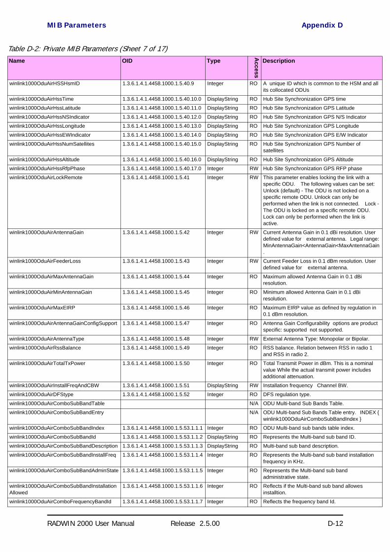
MIB Parameters Appendix D
RADWIN 2000 User Manual Release 2.5.00 D-12
winlink1000OduAirHSSHsmID 1.3.6.1.4.1.4458.1000.1.5.40.9 Integer RO A unique ID which is common to the HSM and all its collocated ODUs
winlink1000OduAirHssTime 1.3.6.1.4.1.4458.1000.1.5.40.10.0 DisplayString RO Hub Site Synchronization GPS time
winlink1000OduAirHssLatitude 1.3.6.1.4.1.4458.1000.1.5.40.11.0 DisplayString RO Hub Site Synchronization GPS Latitude
winlink1000OduAirHssNSIndicator 1.3.6.1.4.1.4458.1000.1.5.40.12.0 DisplayString RO Hub Site Synchronization GPS N/S Indicator
winlink1000OduAirHssLongitude 1.3.6.1.4.1.4458.1000.1.5.40.13.0 DisplayString RO Hub Site Synchronization GPS Longitude
winlink1000OduAirHssEWIndicator 1.3.6.1.4.1.4458.1000.1.5.40.14.0 DisplayString RO Hub Site Synchronization GPS E/W Indicator
winlink1000OduAirHssNumSatellites 1.3.6.1.4.1.4458.1000.1.5.40.15.0 DisplayString RO Hub Site Synchronization GPS Number of satellites
winlink1000OduAirHssAltitude 1.3.6.1.4.1.4458.1000.1.5.40.16.0 DisplayString RO Hub Site Synchronization GPS Altitude
winlink1000OduAirHssRfpPhase 1.3.6.1.4.1.4458.1000.1.5.40.17.0 Integer RW Hub Site Synchronization GPS RFP phase
winlink1000OduAirLockRemote 1.3.6.1.4.1.4458.1000.1.5.41 Integer RW This parameter enables locking the link with a specific ODU. The following values can be set: Unlock (default) - The ODU is not locked on a specific remote ODU. Unlock can only be performed when the link is not connected. Lock - The ODU is locked on a specific remote ODU. Lock can only be performed when the link is active.
winlink1000OduAirAntennaGain 1.3.6.1.4.1.4458.1000.1.5.42 Integer RW Current Antenna Gain in 0.1 dBi resolution. User defined value for external antenna. Legal range: MinAntennaGain<AntennaGain<MaxAntennaGain.
winlink1000OduAirFeederLoss 1.3.6.1.4.1.4458.1000.1.5.43 Integer RW Current Feeder Loss in 0.1 dBm resolution. User defined value for external antenna.
winlink1000OduAirMaxAntennaGain 1.3.6.1.4.1.4458.1000.1.5.44 Integer RO Maximum allowed Antenna Gain in 0.1 dBi resolution.
winlink1000OduAirMinAntennaGain 1.3.6.1.4.1.4458.1000.1.5.45 Integer RO Minimum allowed Antenna Gain in 0.1 dBi resolution.
winlink1000OduAirMaxEIRP 1.3.6.1.4.1.4458.1000.1.5.46 Integer RO Maximum EIRP value as defined by regulation in 0.1 dBm resolution.
winlink1000OduAirAntennaGainConfigSupport 1.3.6.1.4.1.4458.1000.1.5.47 Integer RO Antenna Gain Configurability options are product specific: supported not supported.
winlink1000OduAirAntennaType 1.3.6.1.4.1.4458.1000.1.5.48 Integer RW External Antenna Type: Monopolar or Bipolar.
winlink1000OduAirRssBalance 1.3.6.1.4.1.4458.1000.1.5.49 Integer RO RSS balance. Relation between RSS in radio 1 and RSS in radio 2.
winlink1000OduAirTotalTxPower 1.3.6.1.4.1.4458.1000.1.5.50 Integer RO Total Transmit Power in dBm. This is a nominal value While the actual transmit power includes additional attenuation.
winlink1000OduAirInstallFreqAndCBW 1.3.6.1.4.1.4458.1000.1.5.51 DisplayString RW Installation frequency Channel BW.
winlink1000OduAirDFStype 1.3.6.1.4.1.4458.1000.1.5.52 Integer RO DFS regulation type.
winlink1000OduAirComboSubBandTable N/A ODU Multi-band Sub Bands Table.
winlink1000OduAirComboSubBandEntry N/A ODU Multi-band Sub Bands Table entry. INDEX winlink1000OduAirComboSubBandIndex
winlink1000OduAirComboSubBandIndex 1.3.6.1.4.1.4458.1000.1.5.53.1.1.1 Integer RO ODU Multi-band sub bands table index.
winlink1000OduAirComboSubBandId 1.3.6.1.4.1.4458.1000.1.5.53.1.1.2 DisplayString RO Represents the Multi-band sub band ID.
winlink1000OduAirComboSubBandDescription 1.3.6.1.4.1.4458.1000.1.5.53.1.1.3 DisplayString RO Multi-band sub band description.
winlink1000OduAirComboSubBandInstallFreq 1.3.6.1.4.1.4458.1000.1.5.53.1.1.4 Integer RO Represents the Multi-band sub band installation frequency in KHz.
winlink1000OduAirComboSubBandAdminState 1.3.6.1.4.1.4458.1000.1.5.53.1.1.5 Integer RO Represents the Multi-band sub band administrative state.
winlink1000OduAirComboSubBandInstallationAllowed
1.3.6.1.4.1.4458.1000.1.5.53.1.1.6 Integer RO Reflects if the Multi-band sub band allowes installtion.
winlink1000OduAirComboFrequencyBandId 1.3.6.1.4.1.4458.1000.1.5.53.1.1.7 Integer RO Reflects the frequency band Id.
Table D-2: Private MIB Parameters (Sheet 7 of 17)Name OID Type
Access
Description
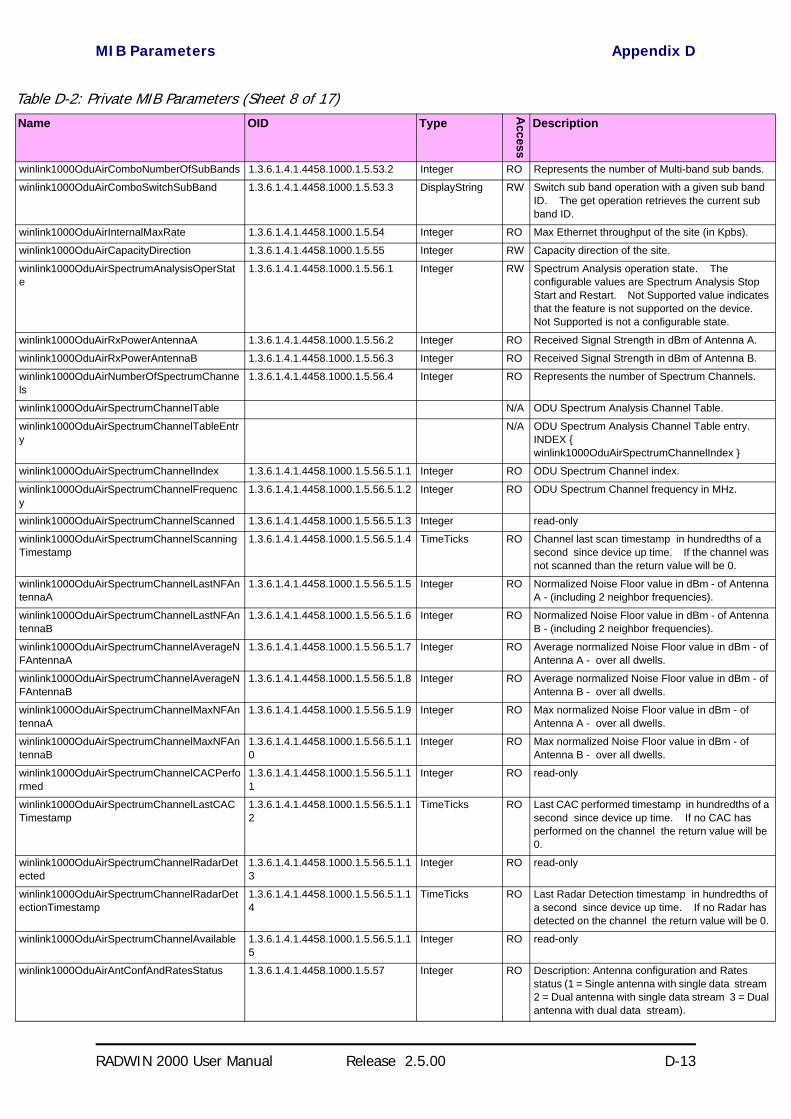
MIB Parameters Appendix D
RADWIN 2000 User Manual Release 2.5.00 D-13
winlink1000OduAirComboNumberOfSubBands 1.3.6.1.4.1.4458.1000.1.5.53.2 Integer RO Represents the number of Multi-band sub bands.
winlink1000OduAirComboSwitchSubBand 1.3.6.1.4.1.4458.1000.1.5.53.3 DisplayString RW Switch sub band operation with a given sub band ID. The get operation retrieves the current sub band ID.
winlink1000OduAirInternalMaxRate 1.3.6.1.4.1.4458.1000.1.5.54 Integer RO Max Ethernet throughput of the site (in Kpbs).
winlink1000OduAirCapacityDirection 1.3.6.1.4.1.4458.1000.1.5.55 Integer RW Capacity direction of the site.
winlink1000OduAirSpectrumAnalysisOperState
1.3.6.1.4.1.4458.1000.1.5.56.1 Integer RW Spectrum Analysis operation state. The configurable values are Spectrum Analysis Stop Start and Restart. Not Supported value indicates that the feature is not supported on the device. Not Supported is not a configurable state.
winlink1000OduAirRxPowerAntennaA 1.3.6.1.4.1.4458.1000.1.5.56.2 Integer RO Received Signal Strength in dBm of Antenna A.
winlink1000OduAirRxPowerAntennaB 1.3.6.1.4.1.4458.1000.1.5.56.3 Integer RO Received Signal Strength in dBm of Antenna B.
winlink1000OduAirNumberOfSpectrumChannels
1.3.6.1.4.1.4458.1000.1.5.56.4 Integer RO Represents the number of Spectrum Channels.
winlink1000OduAirSpectrumChannelTable N/A ODU Spectrum Analysis Channel Table.
winlink1000OduAirSpectrumChannelTableEntry
N/A ODU Spectrum Analysis Channel Table entry. INDEX winlink1000OduAirSpectrumChannelIndex
winlink1000OduAirSpectrumChannelIndex 1.3.6.1.4.1.4458.1000.1.5.56.5.1.1 Integer RO ODU Spectrum Channel index.
winlink1000OduAirSpectrumChannelFrequency
1.3.6.1.4.1.4458.1000.1.5.56.5.1.2 Integer RO ODU Spectrum Channel frequency in MHz.
winlink1000OduAirSpectrumChannelScanned 1.3.6.1.4.1.4458.1000.1.5.56.5.1.3 Integer read-only
winlink1000OduAirSpectrumChannelScanningTimestamp
1.3.6.1.4.1.4458.1000.1.5.56.5.1.4 TimeTicks RO Channel last scan timestamp in hundredths of a second since device up time. If the channel was not scanned than the return value will be 0.
winlink1000OduAirSpectrumChannelLastNFAntennaA
1.3.6.1.4.1.4458.1000.1.5.56.5.1.5 Integer RO Normalized Noise Floor value in dBm - of Antenna A - (including 2 neighbor frequencies).
winlink1000OduAirSpectrumChannelLastNFAntennaB
1.3.6.1.4.1.4458.1000.1.5.56.5.1.6 Integer RO Normalized Noise Floor value in dBm - of Antenna B - (including 2 neighbor frequencies).
winlink1000OduAirSpectrumChannelAverageNFAntennaA
1.3.6.1.4.1.4458.1000.1.5.56.5.1.7 Integer RO Average normalized Noise Floor value in dBm - of Antenna A - over all dwells.
winlink1000OduAirSpectrumChannelAverageNFAntennaB
1.3.6.1.4.1.4458.1000.1.5.56.5.1.8 Integer RO Average normalized Noise Floor value in dBm - of Antenna B - over all dwells.
winlink1000OduAirSpectrumChannelMaxNFAntennaA
1.3.6.1.4.1.4458.1000.1.5.56.5.1.9 Integer RO Max normalized Noise Floor value in dBm - of Antenna A - over all dwells.
winlink1000OduAirSpectrumChannelMaxNFAntennaB
1.3.6.1.4.1.4458.1000.1.5.56.5.1.10
Integer RO Max normalized Noise Floor value in dBm - of Antenna B - over all dwells.
winlink1000OduAirSpectrumChannelCACPerformed
1.3.6.1.4.1.4458.1000.1.5.56.5.1.11
Integer RO read-only
winlink1000OduAirSpectrumChannelLastCACTimestamp
1.3.6.1.4.1.4458.1000.1.5.56.5.1.12
TimeTicks RO Last CAC performed timestamp in hundredths of a second since device up time. If no CAC has performed on the channel the return value will be 0.
winlink1000OduAirSpectrumChannelRadarDetected
1.3.6.1.4.1.4458.1000.1.5.56.5.1.13
Integer RO read-only
winlink1000OduAirSpectrumChannelRadarDetectionTimestamp
1.3.6.1.4.1.4458.1000.1.5.56.5.1.14
TimeTicks RO Last Radar Detection timestamp in hundredths of a second since device up time. If no Radar has detected on the channel the return value will be 0.
winlink1000OduAirSpectrumChannelAvailable 1.3.6.1.4.1.4458.1000.1.5.56.5.1.15
Integer RO read-only
winlink1000OduAirAntConfAndRatesStatus 1.3.6.1.4.1.4458.1000.1.5.57 Integer RO Description: Antenna configuration and Rates status (1 = Single antenna with single data stream 2 = Dual antenna with single data stream 3 = Dual antenna with dual data stream).
Table D-2: Private MIB Parameters (Sheet 8 of 17)Name OID Type
Access
Description

MIB Parameters Appendix D
RADWIN 2000 User Manual Release 2.5.00 D-14
winlink1000OduAirDualAntTxMode 1.3.6.1.4.1.4458.1000.1.5.58 Integer RW Description: Transmission type when using Dual radios (MIMO or AdvancedDiversity using one stream of data).
winlink1000OduAirTxOperationMode 1.3.6.1.4.1.4458.1000.1.5.59 Integer RW This parameter controls the Operation mode of frames sent over the air. The Operation mode is either normal (1) for regular transmission where frame size is determined by the traffic or throughput test (2) when the user requests an actual over the air throughput estimation using full frames. The latter lasts no more than a predetermined interval (default 30 sec).
winlink1000OduAirDesiredNetMasterTxRatio 1.3.6.1.4.1.4458.1000.1.5.60.1 Integer RW This parameter is reserved to the element manager provided with the product.
winlink1000OduAirCurrentNetMasterTxRatio 1.3.6.1.4.1.4458.1000.1.5.60.2 Integer RO Represents the actual Net Master Tx RAtio.
winlink1000OduAirMinUsableMasterTxRatio 1.3.6.1.4.1.4458.1000.1.5.60.3 Integer RO Represents the minimal value the user can configure for Desired net mAster Tx Ratio.
winlink1000OduAirMaxUsableMasterTxRatio 1.3.6.1.4.1.4458.1000.1.5.60.4 Integer RO Represents the maximal value the user can configure for Desired net mAster Tx Ratio.
winlink1000OduAirAccumulatedUAS 1.3.6.1.4.1.4458.1000.1.5.61 Integer RO Accumulates the Unavailable seconds of the Air Interface.
winlink1000OduPerfMonCurrTable N/A This table defines/keeps the counters of the current 15 min interval.
winlink1000OduPerfMonCurrEntry N/A This is an entry in the Current Interval Table. INDEX ifIndex
winlink1000OduPerfMonCurrUAS 1.3.6.1.4.1.4458.1000.1.6.1.1.1 Gauge RO The current number of Unavailable Seconds starting from the present 15 minutes period.
winlink1000OduPerfMonCurrES 1.3.6.1.4.1.4458.1000.1.6.1.1.2 Gauge RO Current number of Errored Seconds starting from the present 15 minutes period.
winlink1000OduPerfMonCurrSES 1.3.6.1.4.1.4458.1000.1.6.1.1.3 Gauge RO Current number of Severely Errored Seconds starting from the present 15 minutes period.
winlink1000OduPerfMonCurrBBE 1.3.6.1.4.1.4458.1000.1.6.1.1.4 Gauge RO Current number of Background Block Errors starting from the present 15 minutes period.
winlink1000OduPerfMonCurrIntegrity 1.3.6.1.4.1.4458.1000.1.6.1.1.5 Integer RO Indicates the integrity of the entry.
winlink1000OduPerfMonIntervalTable N/A This table defines/keeps the counters of the last day (in resolution of 15 min intervals).
winlink1000OduPerfMonIntervalEntry N/A This is an entry in the Interval Table. INDEX ifIndex winlink1000OduPerfMonIntervalIdx
winlink1000OduPerfMonIntervalIdx RO This table is indexed per interval number. Each interval is of 15 minutes and the oldest is 96.
winlink1000OduPerfMonIntervalUAS RO The current number of Unavailable Seconds per interval.
winlink1000OduPerfMonIntervalES RO Current number of Errored Seconds per interval.
winlink1000OduPerfMonIntervalSES RO Current number of Severely Errored Seconds per interval.
winlink1000OduPerfMonIntervalBBE RO Current number of Background Block Errors per interval.
winlink1000OduPerfMonIntervalIntegrity RO Indicates the integrity of the entry per interval.
winlink1000OduPerfMonDayTable N/A This table defines/keeps the counters of the last month (in resolution of days).
winlink1000OduPerfMonDayEntry N/A This is an entry in the Days Table. INDEX ifIndex winlink1000OduPerfMonDayIdx
winlink1000OduPerfMonDayIdx RO This table is indexed per interval number. Each interval is of 24 hours and the oldest is 30.
winlink1000OduPerfMonDayUAS RO The current number of Unavailable Seconds per interval of 24 hours.
Table D-2: Private MIB Parameters (Sheet 9 of 17)Name OID Type
Access
Description
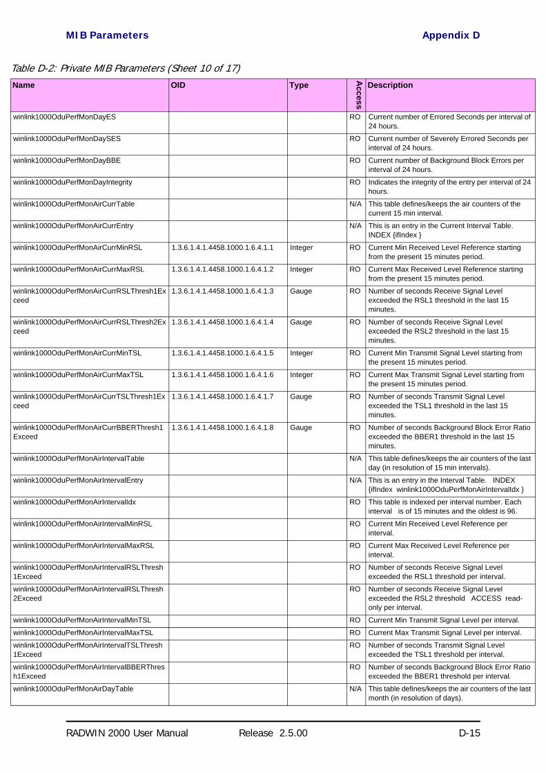
MIB Parameters Appendix D
RADWIN 2000 User Manual Release 2.5.00 D-15
winlink1000OduPerfMonDayES RO Current number of Errored Seconds per interval of 24 hours.
winlink1000OduPerfMonDaySES RO Current number of Severely Errored Seconds per interval of 24 hours.
winlink1000OduPerfMonDayBBE RO Current number of Background Block Errors per interval of 24 hours.
winlink1000OduPerfMonDayIntegrity RO Indicates the integrity of the entry per interval of 24 hours.
winlink1000OduPerfMonAirCurrTable N/A This table defines/keeps the air counters of the current 15 min interval.
winlink1000OduPerfMonAirCurrEntry N/A This is an entry in the Current Interval Table. INDEX ifIndex
winlink1000OduPerfMonAirCurrMinRSL 1.3.6.1.4.1.4458.1000.1.6.4.1.1 Integer RO Current Min Received Level Reference starting from the present 15 minutes period.
winlink1000OduPerfMonAirCurrMaxRSL 1.3.6.1.4.1.4458.1000.1.6.4.1.2 Integer RO Current Max Received Level Reference starting from the present 15 minutes period.
winlink1000OduPerfMonAirCurrRSLThresh1Exceed
1.3.6.1.4.1.4458.1000.1.6.4.1.3 Gauge RO Number of seconds Receive Signal Level exceeded the RSL1 threshold in the last 15 minutes.
winlink1000OduPerfMonAirCurrRSLThresh2Exceed
1.3.6.1.4.1.4458.1000.1.6.4.1.4 Gauge RO Number of seconds Receive Signal Level exceeded the RSL2 threshold in the last 15 minutes.
winlink1000OduPerfMonAirCurrMinTSL 1.3.6.1.4.1.4458.1000.1.6.4.1.5 Integer RO Current Min Transmit Signal Level starting from the present 15 minutes period.
winlink1000OduPerfMonAirCurrMaxTSL 1.3.6.1.4.1.4458.1000.1.6.4.1.6 Integer RO Current Max Transmit Signal Level starting from the present 15 minutes period.
winlink1000OduPerfMonAirCurrTSLThresh1Exceed
1.3.6.1.4.1.4458.1000.1.6.4.1.7 Gauge RO Number of seconds Transmit Signal Level exceeded the TSL1 threshold in the last 15 minutes.
winlink1000OduPerfMonAirCurrBBERThresh1Exceed
1.3.6.1.4.1.4458.1000.1.6.4.1.8 Gauge RO Number of seconds Background Block Error Ratio exceeded the BBER1 threshold in the last 15 minutes.
winlink1000OduPerfMonAirIntervalTable N/A This table defines/keeps the air counters of the last day (in resolution of 15 min intervals).
winlink1000OduPerfMonAirIntervalEntry N/A This is an entry in the Interval Table. INDEX ifIndex winlink1000OduPerfMonAirIntervalIdx
winlink1000OduPerfMonAirIntervalIdx RO This table is indexed per interval number. Each interval is of 15 minutes and the oldest is 96.
winlink1000OduPerfMonAirIntervalMinRSL RO Current Min Received Level Reference per interval.
winlink1000OduPerfMonAirIntervalMaxRSL RO Current Max Received Level Reference per interval.
winlink1000OduPerfMonAirIntervalRSLThresh1Exceed
RO Number of seconds Receive Signal Level exceeded the RSL1 threshold per interval.
winlink1000OduPerfMonAirIntervalRSLThresh2Exceed
RO Number of seconds Receive Signal Level exceeded the RSL2 threshold ACCESS read-only per interval.
winlink1000OduPerfMonAirIntervalMinTSL RO Current Min Transmit Signal Level per interval.
winlink1000OduPerfMonAirIntervalMaxTSL RO Current Max Transmit Signal Level per interval.
winlink1000OduPerfMonAirIntervalTSLThresh1Exceed
RO Number of seconds Transmit Signal Level exceeded the TSL1 threshold per interval.
winlink1000OduPerfMonAirIntervalBBERThresh1Exceed
RO Number of seconds Background Block Error Ratio exceeded the BBER1 threshold per interval.
winlink1000OduPerfMonAirDayTable N/A This table defines/keeps the air counters of the last month (in resolution of days).
Table D-2: Private MIB Parameters (Sheet 10 of 17)Name OID Type
Access
Description

MIB Parameters Appendix D
RADWIN 2000 User Manual Release 2.5.00 D-16
winlink1000OduPerfMonAirDayEntry N/A This is an entry in the Days Table. INDEX ifIndex winlink1000OduPerfMonAirDayIdx
winlink1000OduPerfMonAirDayIdx RO This table is indexed per Day number. Each Day is of 15 minutes and the oldest is 96.
winlink1000OduPerfMonAirDayMinRSL RO Current Min Received Level Reference per Day.
winlink1000OduPerfMonAirDayMaxRSL RO Current Max Received Level Reference per Day.
winlink1000OduPerfMonAirDayRSLThresh1Exceed
RO Number of seconds Receive Signal Level exceeded the RSL1 threshold per Day.
winlink1000OduPerfMonAirDayRSLThresh2Exceed
RO Number of seconds Receive Signal Level exceeded the RSL2 threshold per Day.
winlink1000OduPerfMonAirDayMinTSL RO Current Min Transmit Signal Level per Day.
winlink1000OduPerfMonAirDayMaxTSL RO Current Max Transmit Signal Level per Day.
winlink1000OduPerfMonAirDayTSLThresh1Exceed
RO Number of seconds Transmit Signal Level exceeded the TSL1 threshold per Day.
winlink1000OduPerfMonAirDayBBERThresh1Exceed
RO Number of seconds Background Block Error Ratio exceeded the BBER1 threshold per Day.
winlink1000OduPerfMonEthCurrTable N/A This table defines/keeps the ethernet counters of the current 15 min interval.
winlink1000OduPerfMonEthCurrEntry N/A This is an entry in the Current Interval Table. INDEX ifIndex
winlink1000OduPerfMonEthCurrRxMBytes 1.3.6.1.4.1.4458.1000.1.6.7.1.1 Gauge RO Current RX Mega Bytes starting from the present 15 minutes period.
winlink1000OduPerfMonEthCurrTxMBytes 1.3.6.1.4.1.4458.1000.1.6.7.1.2 Gauge RO Current Transmit Mega Bytes starting from the present 15 minutes period.
winlink1000OduPerfMonEthCurrEthCapacityThreshUnder
1.3.6.1.4.1.4458.1000.1.6.7.1.3 Gauge RO The number of times throughput was below threshold in the present 15 minutes period.
winlink1000OduPerfMonEthCurrHighTrafficThreshExceed
1.3.6.1.4.1.4458.1000.1.6.7.1.4 Gauge RO The number of times actual traffic was above threshold in the present 15 minutes period.
winlink1000OduPerfMonEthCurrActiveSeconds
1.3.6.1.4.1.4458.1000.1.6.7.1.5 Gauge RO The number of seconds in which RPL Ethernet swervice was not blocked in the present 15 minutes period.
winlink1000OduPerfMonEthIntervalTable N/A This table defines/keeps the ethernet counters of the last day (in resolution of 15 min intervals).
winlink1000OduPerfMonEthIntervalEntry N/A This is an entry in the Interval Table. INDEX ifIndex winlink1000OduPerfMonEthIntervalIdx
winlink1000OduPerfMonEthIntervalIdx RO This table is indexed per interval number. Each interval is of 15 minutes and the oldest is 96.
winlink1000OduPerfMonEthIntervalRxMBytes RO Current RX Mega Bytes per interval.
winlink1000OduPerfMonEthIntervalTxMBytes RO Current Transmit Mega Bytes per interval.
winlink1000OduPerfMonEthIntervalEthCapacityThreshUnder
RO The number of times throughput was below threshold in the each interval.
winlink1000OduPerfMonEthIntervalHighTrafficThreshExceed
RO The number of times actual traffic was above threshold in the each interval.
winlink1000OduPerfMonEthIntervalActiveSeconds
RO The number of seconds in which RPL Ethernet service was not blocked in the each interval.
winlink1000OduPerfMonEthDayTable N/A This table defines/keeps the ethernet counters of the last month (in resolution of days).
winlink1000OduPerfMonEthDayEntry N/A This is an entry in the Days Table. INDEX ifIndex winlink1000OduPerfMonEthDayIdx
winlink1000OduPerfMonEthDayIdx RO This table is indexed per Day number. Each interval is of 15 minutes and the oldest is 96.
winlink1000OduPerfMonEthDayRxMBytes RO Current RX Mega Bytes per day.
winlink1000OduPerfMonEthDayTxMBytes RO Current Transmit Mega Bytes per day.
Table D-2: Private MIB Parameters (Sheet 11 of 17)Name OID Type
Access
Description
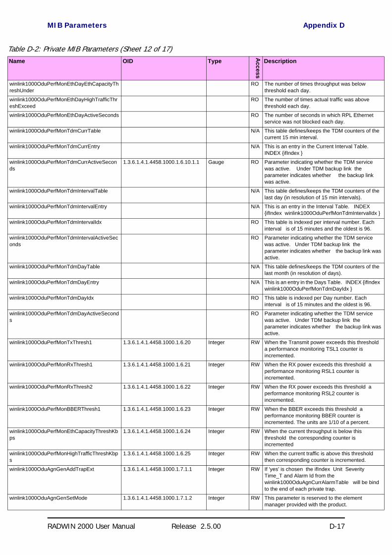
MIB Parameters Appendix D
RADWIN 2000 User Manual Release 2.5.00 D-17
winlink1000OduPerfMonEthDayEthCapacityThreshUnder
RO The number of times throughput was below threshold each day.
winlink1000OduPerfMonEthDayHighTrafficThreshExceed
RO The number of times actual traffic was above threshold each day.
winlink1000OduPerfMonEthDayActiveSeconds RO The number of seconds in which RPL Ethernet service was not blocked each day.
winlink1000OduPerfMonTdmCurrTable N/A This table defines/keeps the TDM counters of the current 15 min interval.
winlink1000OduPerfMonTdmCurrEntry N/A This is an entry in the Current Interval Table. INDEX ifIndex
winlink1000OduPerfMonTdmCurrActiveSeconds
1.3.6.1.4.1.4458.1000.1.6.10.1.1 Gauge RO Parameter indicating whether the TDM service was active. Under TDM backup link the parameter indicates whether the backup link was active.
winlink1000OduPerfMonTdmIntervalTable N/A This table defines/keeps the TDM counters of the last day (in resolution of 15 min intervals).
winlink1000OduPerfMonTdmIntervalEntry N/A This is an entry in the Interval Table. INDEX ifIndex winlink1000OduPerfMonTdmIntervalIdx
winlink1000OduPerfMonTdmIntervalIdx RO This table is indexed per interval number. Each interval is of 15 minutes and the oldest is 96.
winlink1000OduPerfMonTdmIntervalActiveSeconds
RO Parameter indicating whether the TDM service was active. Under TDM backup link the parameter indicates whether the backup link was active.
winlink1000OduPerfMonTdmDayTable N/A This table defines/keeps the TDM counters of the last month (in resolution of days).
winlink1000OduPerfMonTdmDayEntry N/A This is an entry in the Days Table. INDEX ifIndex winlink1000OduPerfMonTdmDayIdx
winlink1000OduPerfMonTdmDayIdx RO This table is indexed per Day number. Each interval is of 15 minutes and the oldest is 96.
winlink1000OduPerfMonTdmDayActiveSeconds
RO Parameter indicating whether the TDM service was active. Under TDM backup link the parameter indicates whether the backup link was active.
winlink1000OduPerfMonTxThresh1 1.3.6.1.4.1.4458.1000.1.6.20 Integer RW When the Transmit power exceeds this threshold a performance monitoring TSL1 counter is incremented.
winlink1000OduPerfMonRxThresh1 1.3.6.1.4.1.4458.1000.1.6.21 Integer RW When the RX power exceeds this threshold a performance monitoring RSL1 counter is incremented.
winlink1000OduPerfMonRxThresh2 1.3.6.1.4.1.4458.1000.1.6.22 Integer RW When the RX power exceeds this threshold a performance monitoring RSL2 counter is incremented.
winlink1000OduPerfMonBBERThresh1 1.3.6.1.4.1.4458.1000.1.6.23 Integer RW When the BBER exceeds this threshold a performance monitoring BBER counter is incremented. The units are 1/10 of a percent.
winlink1000OduPerfMonEthCapacityThreshKbps
1.3.6.1.4.1.4458.1000.1.6.24 Integer RW When the current throughput is below this threshold the corresponding counter is incremented
winlink1000OduPerfMonHighTrafficThreshKbps
1.3.6.1.4.1.4458.1000.1.6.25 Integer RW When the current traffic is above this threshold then corresponding counter is incremented.
winlink1000OduAgnGenAddTrapExt 1.3.6.1.4.1.4458.1000.1.7.1.1 Integer RW If 'yes' is chosen the ifIndex Unit Severity Time_T and Alarm Id from the winlink1000OduAgnCurrAlarmTable will be bind to the end of each private trap.
winlink1000OduAgnGenSetMode 1.3.6.1.4.1.4458.1000.1.7.1.2 Integer RW This parameter is reserved to the element manager provided with the product.
Table D-2: Private MIB Parameters (Sheet 12 of 17)Name OID Type
Access
Description

MIB Parameters Appendix D
RADWIN 2000 User Manual Release 2.5.00 D-18
winlink1000OduAgnNTPCfgTimeServerIP 1.3.6.1.4.1.4458.1000.1.7.2.1 IpAddress RW IP address of the server from which the current time is loaded.
winlink1000OduAgnNTPCfgTimeOffsetFromUTC
1.3.6.1.4.1.4458.1000.1.7.2.2 Integer RW Offset from Coordinated Universal Time (minutes). Possible values: -1440..1440.
winlink1000OduAgnRealTimeAndDate 1.3.6.1.4.1.4458.1000.1.7.2.3 OctetString RW This parameter specifies the real time and date Format 'YYYY-MM-DD HH:MM:SS' (Hexadecimal). A date-time specification: field octets contents range ----- ------ -------- ----- 1 1-2 year 0..65536 2 3 month 1..12 3 4 day 1..31 4 5 hour 0..23 5 6 minutes 0..59 6 7 seconds 0..60 (use 60 for leap-second) 7 8 deci-seconds 0..9 For example Tuesday May 26 1992 at 1:30:15 PM EDT would be displayed as: 07 c8 05 1a 0d 1e 0f 00 ( 1992 -5 -26 13:30:15 )
winlink1000OduAgnCurrAlarmLastChange 1.3.6.1.4.1.4458.1000.1.7.3.1 Integer RO This counter is initialized to 0 after a device reset and is incremented upon each change in the winlink1000OduAgnCurrAlarmTable (either an addition or removal of an entry).
winlink1000OduAgnCurrAlarmTable N/A This table includes the currently active alarms. When a RAISED trap is sent an alarm entry is added to the table. When a CLEAR trap is sent the entry is removed.
winlink1000OduAgnCurrAlarmEntry N/A Entry containing the details of a currently RAISED trap. INDEX winlink1000OduAgnCurrAlarmCounter
winlink1000OduAgnCurrAlarmCounter 1.3.6.1.4.1.4458.1000.1.7.3.2.1.1 Integer RO A running counter of active alarms. The counter is incremented for every new RAISED trap. It is cleared after a device reset.
winlink1000OduAgnCurrAlarmSeverity 1.3.6.1.4.1.4458.1000.1.7.3.2.1.2 Integer RO Current Alarm severity.
winlink1000OduAgnCurrAlarmId 1.3.6.1.4.1.4458.1000.1.7.3.2.1.3 Integer RO Unique Alarm Identifier (combines alarm type and interface). The same AlarmId is used for RAISED and CLEARED alarms.
winlink1000OduAgnCurrAlarmIfIndex 1.3.6.1.4.1.4458.1000.1.7.3.2.1.4 Integer RO Interface Index where the alarm occurred. Alarms that are not associated with a specific interface will have the following value: 65535.
winlink1000OduAgnCurrAlarmUnit 1.3.6.1.4.1.4458.1000.1.7.3.2.1.5 Integer RO Unit associated with the alarm.
winlink1000OduAgnCurrAlarmTrapID 1.3.6.1.4.1.4458.1000.1.7.3.2.1.6 Integer RO ID of the raised trap that was sent when this alarm was raised.
winlink1000OduAgnCurrAlarmTimeT 1.3.6.1.4.1.4458.1000.1.7.3.2.1.7 Integer RO Timestamp of this alarm. This number is in seconds from Midnight January 1st 1970.
winlink1000OduAgnCurrAlarmText 1.3.6.1.4.1.4458.1000.1.7.3.2.1.8 DisplayString RO Alarm display text (same as the text in the sent trap).
winlink1000OduAgnLastEventsNumber 1.3.6.1.4.1.4458.1000.1.7.4.1 Integer RO This counter indicates the size of the winlink1000OduAgnLastEventsTable
winlink1000OduAgnLastEventsTable N/A This table includes the last events. When a trap is sent an event entry is added to the table.
winlink1000OduAgnLastEventsEntry N/A Entry containing the details of last traps. INDEX winlink1000OduAgnLastEventsIndex
winlink1000OduAgnLastEventsIndex 1.3.6.1.4.1.4458.1000.1.7.4.2.1.1 Integer RO The index of the table
winlink1000OduAgnLastEventsSeverity 1.3.6.1.4.1.4458.1000.1.7.4.2.1.2 Integer RO Current Trap severity.
winlink1000OduAgnLastEventsIfIndex 1.3.6.1.4.1.4458.1000.1.7.4.2.1.3 Integer RO Interface Index where the event occurred. Traps that are not associated with a specific interface will have the following value: 65535.
Table D-2: Private MIB Parameters (Sheet 13 of 17)Name OID Type
Access
Description

MIB Parameters Appendix D
RADWIN 2000 User Manual Release 2.5.00 D-19
winlink1000OduAgnLastEventsTimeT 1.3.6.1.4.1.4458.1000.1.7.4.2.1.4 Integer RO Timestamp of this trap. This number is in seconds from Midnight January 1st 1970.
winlink1000OduAgnLastEventsText 1.3.6.1.4.1.4458.1000.1.7.4.2.1.5 DisplayString RO Trap display text (same as the text in the sent trap).
winlink1000IduAdmProductType 1.3.6.1.4.1.4458.1000.2.1.1 DisplayString RO IDU configuration description.
winlink1000IduAdmHwRev 1.3.6.1.4.1.4458.1000.2.1.2 DisplayString RO IDU Hardware Revision.
winlink1000IduAdmSwRev 1.3.6.1.4.1.4458.1000.2.1.3 DisplayString RO IDU Software Revision.
winlink1000OduAdmNumOfExternalAlarmIn 1.3.6.1.4.1.4458.1000.2.1.4 Integer RO Indicates the number of currently available External Alarm Inputs.
winlink1000OduAdmExternAlarmInTable N/A This is the External Alarm Inputs table.
winlink1000OduAdmExternAlarmInEntry N/A Entry containing the elements of a single External Alarm Input. INDEX winlink1000OduAdmExternAlarmInIndex
winlink1000OduAdmExternAlarmInIndex 1.3.6.1.4.1.4458.1000.2.1.5.1.1 Integer RO This value indicates the index of the External Alarm Input entry.
winlink1000OduAdmExternAlarmInText 1.3.6.1.4.1.4458.1000.2.1.5.1.2 DisplayString RW This field describes the External Alarm Input. It is an optional string of no more than 64 characters which will be used in the event being sent as a result of a change in the status of the External Alarm Input. DEFVAL Alarm Description
winlink1000OduAdmExternAlarmInAdminState 1.3.6.1.4.1.4458.1000.2.1.5.1.3 Integer RW This value indicates if this External Alarm Input is enabled or disabled.
winlink1000OduAdmExternAlarmInStatus 1.3.6.1.4.1.4458.1000.2.1.5.1.4 Integer RO This value indicates the current status of the External Alarm Input.
winlink1000IduAdmSN 1.3.6.1.4.1.4458.1000.2.1.6 DisplayString RO IDU Serial Number
winlink1000IduAdmIduDetectionMode 1.3.6.1.4.1.4458.1000.2.1.7 Integer RW The parameter defines whether to send Ethernet frames to detect an IDU. The valid writable values are: userDisabled (3) userEnabled (4). A change requires a reset and is effective after reset.
winlink1000IduAdmMountedTrunks 1.3.6.1.4.1.4458.1000.2.1.8 Integer RO Number of mounted trunks in the IDU
winlink1000IduAdmLicensedTrunks 1.3.6.1.4.1.4458.1000.2.1.9 Integer RO Number of Licensed Trunks in the IDU
winlink1000IduAdmVlanSupported 1.3.6.1.4.1.4458.1000.2.1.10 Integer RO Identifies if the local IDU supports VLAN tag/untag
winlink1000IduAdmVlanEgressMode 1.3.6.1.4.1.4458.1000.2.1.11 DisplayString RW VLAN tag/untag egress values
winlink1000IduAdmVlanIngressMode 1.3.6.1.4.1.4458.1000.2.1.12 DisplayString RW VLAN tag/untag ingress values
winlink1000IduAdmVlanDefaultPortVIDs 1.3.6.1.4.1.4458.1000.2.1.13 DisplayString RW VLAN tag/untag default VLAN ids for each port - Right most digit is Vlan priority (0-6) other digits compose Vlan Id (1-4094)
winlink1000IduAdmVlanLan1UntaggedVIDs 1.3.6.1.4.1.4458.1000.2.1.14 DisplayString RW VLAN untagged VIDs for LAN1 port
winlink1000IduAdmVlanLan2UntaggedVIDs 1.3.6.1.4.1.4458.1000.2.1.15 DisplayString RW VLAN untagged VIDs for LAN2 port
winlink1000IduAdmVlanSfpUntaggedVIDs 1.3.6.1.4.1.4458.1000.2.1.16 DisplayString RW VLAN untagged VIDs for Sfp port
winlink1000IduAdmVlanLan1FilteredVIDs 1.3.6.1.4.1.4458.1000.2.1.17 DisplayString RW VLAN filtered VIDs for LAN1 port
winlink1000IduAdmVlanLan2FilteredVIDs 1.3.6.1.4.1.4458.1000.2.1.18 DisplayString RW VLAN filtered VIDs for LAN2 port
winlink1000IduAdmVlanSfpFilteredVIDs 1.3.6.1.4.1.4458.1000.2.1.19 DisplayString RW VLAN filtered VIDs for Sfp port
winlink1000IduSrvDesiredTrunks 1.3.6.1.4.1.4458.1000.2.2.2 Integer RW Required trunks bitmap. Note that the number of possible trunks that can be configured may vary based on the IDU hardware configuration the selected air interface rate and the range of the installation. The provided Manager application enables the user to select only available configurations. A change is effective immediately if applied to a master unit and the link is in service mode.
winlink1000IduSrvServices 1.3.6.1.4.1.4458.1000.2.2.4 ObjectID RO This parameter is reserved to the Manager application provided with the product.
Table D-2: Private MIB Parameters (Sheet 14 of 17)Name OID Type
Access
Description

MIB Parameters Appendix D
RADWIN 2000 User Manual Release 2.5.00 D-20
winlink1000IduSrvActiveTrunks 1.3.6.1.4.1.4458.1000.2.2.6 Integer RO A bitmap describing the currently open TDM trunks.
winlink1000IduSrvAvailableTrunks 1.3.6.1.4.1.4458.1000.2.2.8 Integer RO A bitmap describing the number of TDM trunks that can be opened in the current configuration. The values take into account the IDU hardware configuration the air rate and the installation range.
winlink1000IduSrvPossibleServicesTable N/A IDU Possible Services table.
winlink1000IduSrvPossibleServicesEntry N/A IDU Services table entry. INDEX winlink1000IduSrvPossibleServicesIndex
winlink1000IduSrvPossibleServicesIndex 1.3.6.1.4.1.4458.1000.2.2.10.1.1 Integer RO Table index Rate index of the air interface.
winlink1000IduSrvPossibleTdmServices 1.3.6.1.4.1.4458.1000.2.2.10.1.2 Integer RO Deprecated parameter. A bitmap describing the TDM trunks that can be opened in the corresponding Air Rate.
winlink1000IduSrvPossibleEthServices 1.3.6.1.4.1.4458.1000.2.2.10.1.3 Integer RO Deprecated parameter. This parameter describes if the Ethernet Service can be opened in the corresponding Air Rate. The valid values are: disabled (0) enabled (1).
winlink1000IduSrvRemainingRate 1.3.6.1.4.1.4458.1000.2.2.10.1.4 Integer RO Current Ethernet bandwidth in bps per air rate.
winlink1000IduSrvTrunkCost 1.3.6.1.4.1.4458.1000.2.2.10.1.5 Integer RO Cost of the TDM Service in bps.
winlink1000IduSrvAvailServicesTable N/A ODU Possible TDM Services table.
winlink1000IduSrvAvailServicesEntry N/A ODU TDM Services table entry. INDEX winlink1000IduSrvAvailServicesIndex
winlink1000IduSrvAvailServicesIndex 1.3.6.1.4.1.4458.1000.2.2.11.1.1 Integer RO Table index. The index is the bit mask of the TDM service.
winlink1000IduSrvAvailServicesState 1.3.6.1.4.1.4458.1000.2.2.11.1.2 Integer RO Represents the TDM service availability.
winlink1000IduSrvAvailServicesMinRateIdx 1.3.6.1.4.1.4458.1000.2.2.11.1.3 Integer RO Minimum rate index of the air interface which make the service possible.
winlink1000IduSrvAvailServicesMaxRateIdx 1.3.6.1.4.1.4458.1000.2.2.11.1.4 Integer RO Maximum rate index of the air interface which make the service possible.
winlink1000IduSrvAvailServicesReason 1.3.6.1.4.1.4458.1000.2.2.11.1.5 Integer RO Information about the TDM Service availability. - Not Applicable if the service is available. The reasons for TDM Service unavailability: - The available throughput isn't sufficient for Service demands; - The IDU HW doesn't support the service; - A Link Password mismatch was detected; - The external pulse type detected is improper for TDM services; - A Software versions mismatch was detected. - A-Symetric TDD Mode Is Obligated.
winlink1000IduSrvEthActive 1.3.6.1.4.1.4458.1000.2.2.12 Integer RO Represents the Ethernet service activation state.
winlink1000IduSrvEthAvailable 1.3.6.1.4.1.4458.1000.2.2.13 Integer RO Represents the Ethernet service availability state.
winlink1000IduSrvEthThroughput 1.3.6.1.4.1.4458.1000.2.2.14 Gauge RO Current available Ethernet service throughput in bps.
winlink1000IduSrvEthMaxInfoRate 1.3.6.1.4.1.4458.1000.2.2.15 Integer RW Holds the maximum bandwidth (kbps) to be allocated for Ethernet service. Value of zero means that Ethernet service works as best effort. The maximum value is product specific. Refer to the user manual.
winlink1000IduSrvAvailableTrunksT1 1.3.6.1.4.1.4458.1000.2.2.16 Integer RO A bitmap describing the TDM trunks that can be opened under T1 configuration. The values take into account the IDU hardware configuration the air rate and the installation range.
winlink1000IduEthernetIfTable N/A IDU Ethernet Interface table.
winlink1000IduEthernetIfEntry N/A IDU Ethernet Interface table entry. INDEX winlink1000IduEthernetIfIndex
Table D-2: Private MIB Parameters (Sheet 15 of 17)Name OID Type
Access
Description
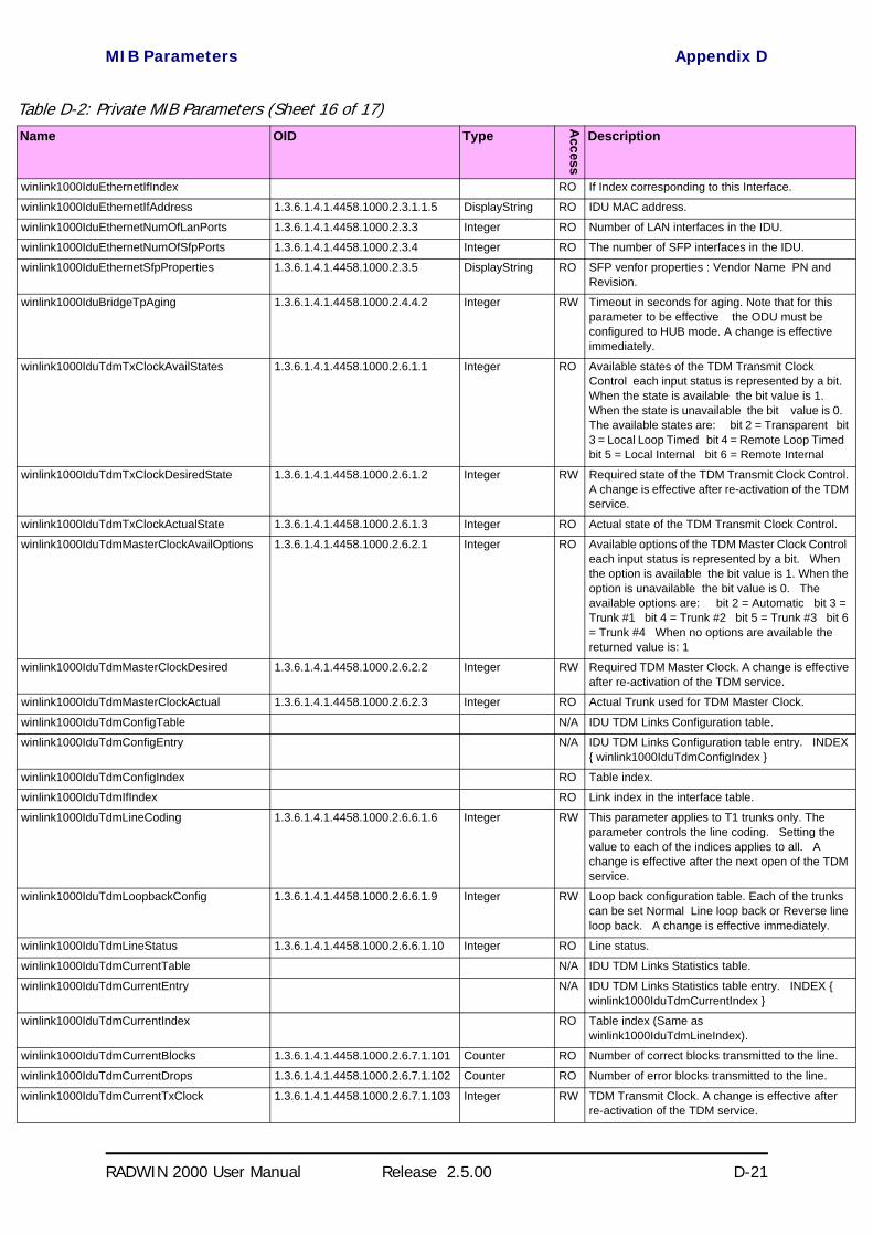
MIB Parameters Appendix D
RADWIN 2000 User Manual Release 2.5.00 D-21
winlink1000IduEthernetIfIndex RO If Index corresponding to this Interface.
winlink1000IduEthernetIfAddress 1.3.6.1.4.1.4458.1000.2.3.1.1.5 DisplayString RO IDU MAC address.
winlink1000IduEthernetNumOfLanPorts 1.3.6.1.4.1.4458.1000.2.3.3 Integer RO Number of LAN interfaces in the IDU.
winlink1000IduEthernetNumOfSfpPorts 1.3.6.1.4.1.4458.1000.2.3.4 Integer RO The number of SFP interfaces in the IDU.
winlink1000IduEthernetSfpProperties 1.3.6.1.4.1.4458.1000.2.3.5 DisplayString RO SFP venfor properties : Vendor Name PN and Revision.
winlink1000IduBridgeTpAging 1.3.6.1.4.1.4458.1000.2.4.4.2 Integer RW Timeout in seconds for aging. Note that for this parameter to be effective the ODU must be configured to HUB mode. A change is effective immediately.
winlink1000IduTdmTxClockAvailStates 1.3.6.1.4.1.4458.1000.2.6.1.1 Integer RO Available states of the TDM Transmit Clock Control each input status is represented by a bit. When the state is available the bit value is 1. When the state is unavailable the bit value is 0. The available states are: bit 2 = Transparent bit 3 = Local Loop Timed bit 4 = Remote Loop Timed bit 5 = Local Internal bit 6 = Remote Internal
winlink1000IduTdmTxClockDesiredState 1.3.6.1.4.1.4458.1000.2.6.1.2 Integer RW Required state of the TDM Transmit Clock Control. A change is effective after re-activation of the TDM service.
winlink1000IduTdmTxClockActualState 1.3.6.1.4.1.4458.1000.2.6.1.3 Integer RO Actual state of the TDM Transmit Clock Control.
winlink1000IduTdmMasterClockAvailOptions 1.3.6.1.4.1.4458.1000.2.6.2.1 Integer RO Available options of the TDM Master Clock Control each input status is represented by a bit. When the option is available the bit value is 1. When the option is unavailable the bit value is 0. The available options are: bit 2 = Automatic bit 3 = Trunk #1 bit 4 = Trunk #2 bit 5 = Trunk #3 bit 6 = Trunk #4 When no options are available the returned value is: 1
winlink1000IduTdmMasterClockDesired 1.3.6.1.4.1.4458.1000.2.6.2.2 Integer RW Required TDM Master Clock. A change is effective after re-activation of the TDM service.
winlink1000IduTdmMasterClockActual 1.3.6.1.4.1.4458.1000.2.6.2.3 Integer RO Actual Trunk used for TDM Master Clock.
winlink1000IduTdmConfigTable N/A IDU TDM Links Configuration table.
winlink1000IduTdmConfigEntry N/A IDU TDM Links Configuration table entry. INDEX winlink1000IduTdmConfigIndex
winlink1000IduTdmConfigIndex RO Table index.
winlink1000IduTdmIfIndex RO Link index in the interface table.
winlink1000IduTdmLineCoding 1.3.6.1.4.1.4458.1000.2.6.6.1.6 Integer RW This parameter applies to T1 trunks only. The parameter controls the line coding. Setting the value to each of the indices applies to all. A change is effective after the next open of the TDM service.
winlink1000IduTdmLoopbackConfig 1.3.6.1.4.1.4458.1000.2.6.6.1.9 Integer RW Loop back configuration table. Each of the trunks can be set Normal Line loop back or Reverse line loop back. A change is effective immediately.
winlink1000IduTdmLineStatus 1.3.6.1.4.1.4458.1000.2.6.6.1.10 Integer RO Line status.
winlink1000IduTdmCurrentTable N/A IDU TDM Links Statistics table.
winlink1000IduTdmCurrentEntry N/A IDU TDM Links Statistics table entry. INDEX winlink1000IduTdmCurrentIndex
winlink1000IduTdmCurrentIndex RO Table index (Same as winlink1000IduTdmLineIndex).
winlink1000IduTdmCurrentBlocks 1.3.6.1.4.1.4458.1000.2.6.7.1.101 Counter RO Number of correct blocks transmitted to the line.
winlink1000IduTdmCurrentDrops 1.3.6.1.4.1.4458.1000.2.6.7.1.102 Counter RO Number of error blocks transmitted to the line.
winlink1000IduTdmCurrentTxClock 1.3.6.1.4.1.4458.1000.2.6.7.1.103 Integer RW TDM Transmit Clock. A change is effective after re-activation of the TDM service.
Table D-2: Private MIB Parameters (Sheet 16 of 17)Name OID Type
Access
Description

MIB Parameters Appendix D
RADWIN 2000 User Manual Release 2.5.00 D-22
winlink1000IduTdmCurrentBlocksHigh 1.3.6.1.4.1.4458.1000.2.6.7.1.104 Counter RO High part of the 64 bits counter Current Blocks
winlink1000IduTdmRemoteQual 1.3.6.1.4.1.4458.1000.2.6.8 Integer RO Estimated average interval between error second events. The valid values are 1-2^31 where a value of -1 is used to indicate an undefined state.
winlink1000IduTdmRemoteQualEval 1.3.6.1.4.1.4458.1000.2.6.9 Integer RO Estimated average interval between error second events during evaluation process. The valid values are 1-2^31 where a value of -1 is used to indicate an undefined state.
winlink1000IduTdmSrvEval 1.3.6.1.4.1.4458.1000.2.6.10 Integer RW Evaluated TDM service bit mask. Setting this parameter to value that is bigger than the activated TDM service bit mask will execute the evaluation process for 30 seconds. Setting this parameter to 0 will stop the evaluation process immediately.
winlink1000IduTdmBackupAvailableLinks 1.3.6.1.4.1.4458.1000.2.6.11 Integer RO Number of TDM backup trunks.
winlink1000IduTdmBackupTable N/A IDU TDM Links Statistics table.
winlink1000IduTdmBackupEntry N/A IDU TDM Links Statistics table entry. INDEX winlink1000IduTdmBackupIndex
winlink1000IduTdmBackupIndex 1.3.6.1.4.1.4458.1000.2.6.12.1.1 Integer RO Table index.
winlink1000IduTdmBackupMode 1.3.6.1.4.1.4458.1000.2.6.12.1.2 Integer RW TDM backup mode: Enable or Disable where the main link is the air link or the external link. Changes will be effective immediatly.
winlink1000IduTdmBackupCurrentActiveLink 1.3.6.1.4.1.4458.1000.2.6.12.1.3 Integer RO TDM backup current active link: N/A air link is active or external link is active.
winlink1000IduTdmJitterBufferSize 1.3.6.1.4.1.4458.1000.2.6.13 Integer RW TDM Jitter Buffer Size. The value must be between the minimum and the maximum TDM Jitter Buffer Size. The units are 0.1 x millisecond.
winlink1000IduTdmJitterBufferDefaultSize 1.3.6.1.4.1.4458.1000.2.6.14 Integer RO TDM Jitter Buffer Default Size. The units are 0.1 x millisecond.
winlink1000IduTdmJitterBufferMinSize 1.3.6.1.4.1.4458.1000.2.6.15 Integer RO TDM Jitter Buffer Minimum Size. The units are 0.1 x millisecond.
winlink1000IduTdmJitterBufferMaxSize 1.3.6.1.4.1.4458.1000.2.6.16 Integer RO TDM Jitter Buffer Maximum Size. The units are 0.1 x millisecond.
winlink1000IduTdmJitterBufferSizeEval 1.3.6.1.4.1.4458.1000.2.6.17 Integer RW TDM Jitter Buffer Size for evaluation. The value must be between the minimum and the maximum TDM Jitter Buffer Size. The units are 0.1 x millisecond.
winlink1000IduTdmType 1.3.6.1.4.1.4458.1000.2.6.18 Integer RW TDM Type (The value undefined is read-only).
winlink1000IduTdmTypeEval 1.3.6.1.4.1.4458.1000.2.6.19 Integer RW TDM Type for evaluation.
winlink1000IduTdmLineStatusStr 1.3.6.1.4.1.4458.1000.2.6.20 DisplayString RO Line status.
winlink1000IduTdmHotStandbySupport 1.3.6.1.4.1.4458.1000.2.6.21 Integer RO Indicates if Hot Standby is supported.
winlink1000IduTdmDesiredHotStandbyMode 1.3.6.1.4.1.4458.1000.2.6.22 Integer RW Desired Hot Standby Mode.
winlink1000IduTdmHotStandbyOperationStatus
1.3.6.1.4.1.4458.1000.2.6.23 Integer RO The Link Actual Status.
winlink1000IduTdmBackupLinkConfiguration 1.3.6.1.4.1.4458.1000.2.6.24 Integer RW The current configuration of the backup link.
winlink1000GeneralTrapDescription 1.3.6.1.4.1.4458.1000.100.1 DisplayString RO Trap's Description. Used for Trap parameters.
winlink1000GeneralTrapSeverity 1.3.6.1.4.1.4458.1000.100.2 Integer RO Trap's Severity. Used for Trap parameters.
winlink1000GeneralCookie 1.3.6.1.4.1.4458.1000.100.3 DisplayString RW Reserved for the Manager application provided with the product used for saving user preferences affecting ODU operation.
winlink1000GeneralEcChangesCounter 1.3.6.1.4.1.4458.1000.100.4 Integer RO This counter is initialized to 0 after a device reset and is incremented upon each element constant write operation via SNMP or Telnet.
winlink1000GeneralTelnetSupport 1.3.6.1.4.1.4458.1000.100.5 Integer RW Enable/Disable Telnet protocol.
Table D-2: Private MIB Parameters (Sheet 17 of 17)Name OID Type
Access
Description

MIB Traps Appendix D
RADWIN 2000 User Manual Release 2.5.00 D-23
MIB Traps
GeneralEach ODU can be configured with up to 10 different trap destinations. When the link is operational, each ODU sends traps originating from both Site A and Site B.
The source IP address of the trap is the sending ODU. The trap originator can be identified by the trap Community string or by the trap description text.
Each trap contains a trap description and additional relevant information such as alarm severity, interface index, time stamp and additional parame-ters.

Trap Parameters Appendix D
RADWIN 2000 User Manual Release 2.5.00 D-24
Trap ParametersTable D-3: MIB Traps (Sheet 1 of 5)Name ID Severity DescriptiontrunkStateChanged 1 normal Indicates a change in the state of one of the TDM trunks. Raised by both
sides of the link. Contains 3 parameters: 1 - Description: TDM Interface %n - %x 2 - %n: Is the trunk number 3 - %x: Is the alarm type and can be one of the following: Normal AIS LOS Loopback
linkUp 2 normal Indicates that the radio link is up. Contains a single parameter which is its description: 1 - Description: Radio Link - Sync on channel %n GHz. %n Is the channel frequency in GHz.
linkDown 3 critical Indicates that the radio link is down. Contains a single parameter which is its description: 1 - Description: Radio Link - Out of Sync. The reason is: %s. %s Is the reason.
detectIDU 4 normal Indicates that the IDU was detected. Raised by both sides of the link. Contains a single parameter which is its description: 1 - Description: IDU of Type %s was Detected. %s Is the type of the IDU.
disconnectIDU 5 major Indicates that the IDU was disconnected. Raised by both sides of the link. Contains a single parameter which is its description: 1 - Description: IDU Disconnected.
mismatchIDU 6 major Indicates a mismatch between the IDUs. Raised by the master only. Contains a single parameter which is its description: 1 - Description: IDUs Mismatch: One Side is %s and the Other is %s. %s Is the type of the IDU.
openedServices 7 normal Indicates that services were opened. Raised by the master only. Contains 3 parameters: 1 - Description: %n2 out of %n1 Requested TDM Trunks have been Opened 2 - %n1: Is the requested number of TDM truncks 3 - %n2: Is the actual number of TDM trunks that were opened
closedServices 8 normal Indicates that services were closed. Raised by the master only. Contains a single parameter which is its description: 1 - Description: TDM Service has been closed. The reason is: %s. %s Is the reason.
incompatibleODUs 9 critical Indicates that the ODUs are incompatible. Contains a single parameter which is its description: 1 - Description: Incompatible ODUs.
incompatibleIDUs 10 major Indicates that the IDUs are incompatible. Contains a single parameter which is its description: 1 - Description: Incompatible IDUs.
incompatibleOduIdu 11 major Indicates that the ODU and IDU are incompatible. Contains a single parameter which is its description: 1 - Description: The IDU could not be loaded. The reason is: %s. %s Is the incompatibility type.
probingChannel 12 normal Indicates that the ODU is monitoring radar activity. Contains a single parameter which is its description: 1 - Description: Monitoring for radar activity on channel %n GHz. %n is the channel frequency in GHz.
radarDetected 13 normal Indicates that radar activity was detected. Contains a single parameter which is its description: 1 - Description: Radar activity was detected in %s on channel %n GHz. %s Is the site name. %n Is the channel frequency in GHz.
transmittingOnChannel 14 normal Indicates that the ODU is transmitting on channel. Contains a single parameter which is its description: 1 - Description: Transmitting on channel %n GHz. %n Is the channel frequency in GHz.
scanningChannels 15 normal Indicates that the ODU is scanning channels. Contains a single parameter which is its description: 1 - Description: Channel scanning in progress.
incompatiblePartner 16 critical Indicates that configuration problem was detected and that link installation is required in order to fix it. Contains a single parameter which is its description: 1 - Description: Configuration problem detected. Link installation required.
timeClockSet 17 normal Indicates that the ODU time clock was set. Contains a single parameter which is its description: 1 - Description: The time was set to: %p. %p Is the date and time.
configurationChanged 18 normal Indicates that the ODU recovered from an error but there are configuration changes. Contains two parameters: 1 - Description: Configuration changed. Error code is: %n. 2 - %n number.
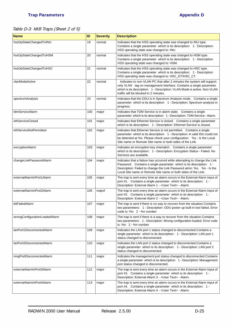
Trap Parameters Appendix D
RADWIN 2000 User Manual Release 2.5.00 D-25
hssOpStateChangedToINU 19 normal Indicates that the HSS operating state was changed to INU type. Contains a single parameter which is its description: 1 - Description: HSS operating state was changed to: INU.
hssOpStateChangedToHSM 20 normal Indicates that the HSS operating state was changed to HSM type. Contains a single parameter which is its description: 1 - Description: HSS operating state was changed to: HSM.
hssOpStateChangedToHSC 21 normal Indicates that the HSS operating state was changed to HSC type. Contains a single parameter which is its description: 1 - Description: HSS operating state was changed to: HSC_DT/HSC_CT.
vlanModeActive 22 normal Indicates to non-VLAN PC that after 2 minutes the system will support only VLAN tag on management interface. Contains a single parameter which is its description: 1 - Description: VLAN Mode is active. Non-VLAN traffic will be blocked in 2 minutes.
spectrumAnalysis 23 normal Indicates that the ODU is in Spectrum Analysis mode. Contains a single parameter which is its description: 1 - Description: Spectrum analysis in progress.
tdmServiceAlarm 100 major Indicates that TDM Service is in alarm state. Contains a single parameter which is its description: 1 - Description: TDM Service - Alarm.
ethServiceClosed 101 major Indicates that Ethernet Service is closed. Contains a single parameter which is its description: 1 - Description: Ethernet Service is closed.
ethServiceNotPermitted 102 major Indicates that Ethernet Service is not permitted. Contains a single parameter which is its description: 1 - Description: A valid IDU could not be detected at %s. Please check your configuration. %s - Is the Local Site name or Remote Site name or both sides of the Link.
encryptionAlarm 103 major Indicates an encryption key mismatch. Contains a single parameter which is its description: 1 - Description: Encryption Status - Failed. No Services are available.
changeLinkPasswordAlarm 104 major Indicates that a failure has occurred while attempting to change the Link Password. Contains a single parameter which is its description: 1 - Description: Failed to change the Link Password at/on: %s. %s - Is the Local Site name or Remote Site name or both sides of the Link.
externalAlarmInPort1Alarm 105 major The trap is sent every time an alarm occurs in the External Alarm Input of port #1. Contains a single parameter which is its description: 1 - Description: External Alarm 1 - <User Text> - Alarm.
externalAlarmInPort2Alarm 106 majorl The trap is sent every time an alarm occurs in the External Alarm Input of port #2. Contains a single parameter which is its description: 1 - Description: External Alarm 2 - <User Text> - Alarm.
bitFailedAlarm 107 major The trap is sent if there is no way to recover from the situation.Contains two parameters: 1 - Description: ODU power up built in test failed. Error code is: %n 2 - %n number
wrongConfigurationLoadedAlarm 108 major The trap is sent if there is a way to recover from the situation.Contains two parameters: 1 - Description: Wrong configuration loaded. Error code is: %n 2 - %n number
lanPort1DisconnectedAlarm 109 major Indicates the LAN port 1 status changed to disconnected.Contains a single parameter which is its description: 1 - Description: LAN port 1 status changed to disconnected.
lanPort2DisconnectedAlarm 110 major Indicates the LAN port 2 status changed to disconnected.Contains a single parameter which is its description: 1 - Description: LAN port 2 status changed to disconnected.
mngPortDisconnectedAlarm 111 major Indicates the management port status changed to disconnected.Contains a single parameter which is its description: 1 - Description: Management port status changed to disconnected.
externalAlarmInPort3Alarm 112 major The trap is sent every time an alarm occurs in the External Alarm Input of port #3. Contains a single parameter which is its description: 1 - Description: External Alarm 3 - <User Text> - Alarm.
externalAlarmInPort4Alarm 113 major The trap is sent every time an alarm occurs in the External Alarm Input of port #4. Contains a single parameter which is its description: 1 - Description: External Alarm 4 - <User Text> - Alarm.
Table D-3: MIB Traps (Sheet 2 of 5)Name ID Severity Description

Trap Parameters Appendix D
RADWIN 2000 User Manual Release 2.5.00 D-26
swVersionsMismatchFullCompatibilityAlarm 114 warning The trap is sent if SW versions mismatch with full link functionality. Contains a single parameter which is its description: 1 - Description: Software versions mismatch - full link functionality
swVersionsMismatchRestrictedCompatibilityAlarm 115 minor The trap is sent if SW versions mismatch with restricted link functionality. Contains a single parameter which is its description: 1 - Description: Software versions mismatch - restricted link functionality
swVersionsMismatchSoftwareUpgradeRequired 116 major The trap is sent if SW versions mismatch and SW upgrade is required. Contains a single parameter which is its description: 1 - Description: Software versions mismatch - Software upgrade required
swVersionsIncompatible 117 critical The trap is sent if SW versions are incompatible. Contains a single parameter which is its description: 1 - Description: SW Versions incompatible
hssMultipleSourcesDetectedAlarm 118 major Indicates that multiple sync pulse sources were detected. Contains a single parameter which is its description: 1 - Description: HSS multiple sync sources were detected.
hssSyncToProperSourceStoppedAlarm 119 major Indicates that synchronization to a proper sync pulse source was stopped. Contains a single parameter which is its description: 1 - Description: HSS sync pulse - Down. The reason is: %s. %s - Is the reason for the sync down.
hssSyncPulseDetectedAlarm 120 major Indicates that HSS additional sync pulse was detected. Contains a single parameter which is its description: 1 - Description: HSS additional sync pulse was detected.
tdmBackupAlarm 121 major Indicates that the TDM backup link was activated. Contains a single parameter which is its description: 1 - Description: TDM backup alarm - backup link was activated.
linkLockUnauthorizedRemoteODU 122 major Indicates that the remote ODU is unauthorized. Contains a single parameter which is its description: 1 - Description: Unauthorized remote ODU connection rejected.
linkLockUnauthorizedODU 123 major Indicates that the ODU is unauthorized. Contains a single parameter which is its description: 1 - Description: Unauthorized ODU connection rejected.
hotStandbyAlarm 124 major Indicates that the hot standby secondary link was activated. Contains a single parameter which is its description: 1 - Description: Secondary Link Is Active.
sfpInsertion 126 normal Indicates that a device was inserted to SFP Port
sfpPort1DisconnectedAlarm 127 major Indicates the SFP port 1 status changed to disconnected.Contains a single parameter which is its description: 1 - Description: SFP port 1 status changed to disconnected.
desiredRatioCanNotBeAppliedAlarm 129 normal Indicates Desired UL/DL RAtio Can Not Be Applied.
cbwMismatch 130 major Indicates that a Channel Bandwidth mismatch was detected.Contains two parameters: 1 - Description: Channel Bandwidth Mismatch: one side is %n0 MHz and the other is %n1 MHz. %n0 is the local Channel Bandwidth value in MHz. %n1 is the remoet Channel Bandwidth value in MHz.
gpsNotSynchronized 131 major Indicates that the GPS is not synchronized with satellites. Pulses are self generated.
tdmServiceClear 200 major Indicates that TDM Service fault is cleared. Contains a single parameter which is its description: 1 - Description: TDM Service - Normal.
ethServiceOpened 201 normal Indicates that Ethernet Service has been opened. Contains a single parameter which is its description: 1 - Description: Ethernet Service has been opened.
encryptionClear 203 normal Indicates that encryption is OK. Contains a single parameter which is its description: 1 - Description: Encryption Status - Normal.
changeLinkPasswordClear 204 normal Indicates that the Link Password was changed successfully. Contains a single parameter which is its description: 1 - Description: Link Password has been changed at/on: %s. %s - Is the Local Site name or Remote Site name or both sides of the Link.
Table D-3: MIB Traps (Sheet 3 of 5)Name ID Severity Description

Trap Parameters Appendix D
RADWIN 2000 User Manual Release 2.5.00 D-27
externalAlarmInPort1Clear 205 normal This Trap is sent every time an External Alarm Input fault of port # 1 is cleared. Contains a single parameter which is its description: 1 - Description: External Alarm 1 - <User Text> - Alarm Cleared.
externalAlarmInPort2Clear 206 normal This Trap is sent every time an External Alarm Input fault of port # 2 is cleared. Contains a single parameter which is its description: 1 - Description: External Alarm 2 - <User Text> - Alarm Cleared.
lanPort1Clear 209 normal Indicates the LAN port 1 status changed to connected. Contains two parameters: 1 - Description: LAN port 1 status changed to connected - %s 2 - %s Is the Eth. mode (speed & duplex)
lanPort2Clear 210 normal Indicates the LAN port 2 status changed to connected. Contains two parameters: 1 - Description: LAN port 2 status changed to connected - %s. 2 - %s Is the Eth. mode (speed & duplex).
mngPortClear 211 normal Indicates the management port status changed to connected. Contains two parameters: 1 - Description: Management port status changed to connected - %s 2 - %s Is the Eth. mode (speed & duplex)
externalAlarmInPort3Clear 212 normal This Trap is sent every time an External Alarm Input fault of port # 3 is cleared. Contains a single parameter which is its description: 1 - Description: External Alarm 3 - <User Text> - Alarm Cleared.
externalAlarmInPort4Clear 213 normal This Trap is sent every time an External Alarm Input fault of port # 4 is cleared. Contains a single parameter which is its description: 1 - Description: External Alarm 4 - <User Text> - Alarm Cleared.
swVersionsMatchFullCompatibilityClear 214 normal The trap is sent if SW versions match. Contains a single parameter which is its description: 1 - Description: Software Versions compatible
swVersionsMatchRestrictedCompatibilityClear 215 normal The trap is sent if SW versions match and link functionality is not restricted. Contains a single parameter which is its description: 1 - Description: Software Versions compatible
swVersionsMatchSoftwareUpgradeRequiredClear 216 normal The trap is sent if SW versions match and SW upgrade is successful. Contains a single parameter which is its description: 1 - Description: Software Versions compatible
swVersionsCompatibleClear 217 normal The trap is sent if SW versions compatible Contains a single parameter which is its description: 1 - Description: Software Versions compatible
hssMultipleSourcesDisappearedClear 218 normal Indicates that multiple sync pulse sources disappeared. Contains a single parameter which is its description: 1 - Description: HSS multiple sync pulse sources disappeared.
hssSyncToProperSourceAchievedClear 219 normal Indicates that synchronization to a proper Sync source was achieved. Contains a single parameter which is its description: 1 - Description: HSS sync pulse - Up.
hssSyncPulseDisappearedClear 220 normal Indicates that HSS additional sync pulse disappeared. Contains a single parameter which is its description: 1 - Description: HSS additional sync pulse was disappeared.
tdmBackupClear 221 normal Indicates that the TDM main link was activated. Contains a single parameter which is its description: 1 - Description: TDM main link was activated.
linkLockAuthorizedRemoteODU 222 normal Indicates that the remote ODU is authorized. Contains a single parameter which is its description: 1 - Description: Authorized remote ODU connection accepted.
linkLockAuthorizedODU 223 normal Indicates that the ODU is authorized. Contains a single parameter which is its description: 1 - Description: Authorized ODU connection permitted.
linkAuthenticationDisabled 224 normal Indicates that the Link Lock is disabled. Contains a single parameter which is its description: 1 - Description: Link Authentication has been disabled.
hotStandbyClear 225 normal Indicates that the Primary Link Was Activated. Contains a single parameter which is its description: 1 - Description: Primary Link Is Active.
sfpExtraction 226 normal Indicates that a device was extracted from SFP Port
sfpPort1Clear 227 normal Indicates the SFP port 1 status changed to connected. Contains two parameters: 1 - Description: SFP port 1 status changed to connected - %s 2 - %s Is the Eth. mode (speed & duplex)
Table D-3: MIB Traps (Sheet 4 of 5)Name ID Severity Description

RADWIN Manager Traps Appendix D
RADWIN 2000 User Manual Release 2.5.00 D-28
RADWIN Manager TrapsThe RADWIN Manager application issues traps to indicate various events. These traps are shown in the RADWIN Managerr Events Log.
A list of Trap Messages as displayed by the RADWIN Manager is shown in Table 9-5.
compatibleIdus 228 normal Indicates that the ODU has identified compatible Idus on both sides of the link.
desiredRatioCanNotBeAppliedClear 229 normal Indicates Current UL/DL Ratio Is Equal To Desired Ratio.
cbwMatch 230 normal Indicates that a Channel Bandwidth match was detected. Contains a single parameter which is its description: 1 - Channel Bandwidth value in MHz.
switchCbwAndChannel 231 normal Indicates that the system is switching Channel Bandwidth and channel frequency. Contains two parameters: 1 - Switching to Channel Bandwith %n0 MHz and to channel %n1 GHz.
ringRplStateIdle 232 normal RPL state changed to Idle.
ringEthServiceStatus 233 normal Indicates Ethernet service's state - blocked \ unblocked. Contains a single parameter: 1 - Description: Ethernet's state (blocked \ unblocked)
ringFirstRpmReceived 234 normal Ring application: in non-RPL link indicates first from a specific RPL was received. Contains a single parameter: 1 - Description: RPM's VLAN ID
ringEthernetSrviceUnblockedTO 235 normal Ring application: in non-RPL link Ethernet service is unblocked due to RPM timeout.
gpsSynchronized 236 normal Indicates that the GPS is synchronized with satellites.
Table D-3: MIB Traps (Sheet 5 of 5)Name ID Severity Description

RADWIN 2000 User Manual Release 2.5.00 E-1
Appendix E
External AlarmsSpecification
External Alarms SpecificationThe IDU-C and new style IDU-E support external input and output alarms through a standard DB25 pin female connector (see page B-3 for pinout details).
Input alarms
The input alarms are raised by events from external equipment, such as a fire warning, door open or air conditioner failure. They are user defined.
Output alarms
Output alarms are generated through dry contact relays to indicate vari-ous system events such as sync loss or disconnection. An alarm is raised if at least one of the conditions in one of the tables below, is met.
IDU-C and new style IDU-E Alarms Table E-1: IDU-C/E - Output Alarms Description
Alarm Description Alarm On Conditions Alarm Off Condition
Output 1 Air interface Alarm• Link is down• Link in installation mode• Link authentication problem
Link is up or equipment alarm is ON
Output 2 Equipment Alarm• Built in Test (BIT) error• No connection to the ODU
Both ODU and IDU are in operational state
Output 3 Service Alarm at Site B N/A Permanently off
Output 4 Power Failure at Site B Link Loss due to Power Failure at Site BLink is up or down without power failure indication within the last two seconds

IDU-C and new style IDU-E Alarms Appendix E
RADWIN 2000 User Manual Release 2.5.00 E-2
Table E-2: IDU-C - Input Alarms Description
Alarm Description Alarm On Conditions
Alarm Off Condition
Input 1
User Defined External Alarm
Voltage in range -10 to -50VDC
Voltage > 0VDCInput 2
Input 3
Input 4

RADWIN 2000 User Manual Release 2.5.00 F-1
Appendix F
RF ExposureThe antennas used for the following transmitters must be installed so as to provide a minimum separation distance from by-standers as specified in the following tables:
Table F-1: Safety Distances for RADWIN 2000 FCC and IC Products
Frequency Band [GHz] FCC ID IC ID Antenna
gain [dBi]Min. Safety Distance [cm]
5.8 Q3KRW2058 5100A-RW2054 28 223
5.8 Q3KRW2058 5100A-RW2054 24 141
5.3/5.4 Q3KRW2054 5100A-RW2054 23.5 / 28 20
4.9 Q3KRW2049 5100A-RW2054 28 225
4.9 Q3KRW2049 5100A-RW2054 21 113
2.4 Q3KRW2024 5100A-RW2054 19 39
2.4 Q3KRW2024I 5100A-RW2024I 17.5 40
Table F-2: Safety Distances for RADWIN 2000 ETSI Products
Frequency Band [GHz]
Antenna gain [dBi]
Min. Safety Distance [cm]
5.8 24 / 28 16
5.4 23.5 / 28 9
5.3 23.5 / 28 4
2.4 19 / 17.5 3

RADWIN 2000 User Manual Release 2.5.00 G-1
Appendix G
Regional Notice: FrenchCanadian
Procédures de sécurité
GénéralitésAvant de manipuler du matériel connecté à des lignes électriques ou de télécommunications, il est conseillé de se défaire de bijoux ou de tout autre objet métallique qui pourrait entrer en contact avec les éléments sous ten-sion.
Mise à la terreTous les produits RADWIN doivent être mis à la terre pendant l'usage cou-rant. La mise à la terre est assurée en reliant la fiche d'alimentation à une prise de courant avec une protection de terre. En outre:
• La cosse de masse sur l'IDU-C doit être constamment connectée à la protection de terre, par un câble de diamètre de 18 AWG ou plus. Le matériel monté sur rack doit être installé seulement sur des racks ou armoires reliés à la terre
• Une ODU doit mise à la terre par un câble de diamètre de 12 AWG ou plus
• Il ne doit pas y avoir de fusibles ou d'interrupteurs sur la connection à la terre
De plus:
• Il faut toujours connecter la terre en premier et la déconnecter en dernier
• Il ne faut jamais connecter les câbles de télécommunication à du matériel non à la terre
• Il faut s'assurer que tous les autres câbles sont déconnectés avant de déconnecter la terre

Protection contre la foudre Appendix G
RADWIN 2000 User Manual Release 2.5.00 G-2
Protection contre la foudreL'utilisation de dispositifs de protection contre la foudre dépend des exi-gences réglementaires et de l'utilisateur final. Toutes les unités extérieures RADWIN sont conçues avec des circuits de limitation de surtension afin de minimiser les risques de dommages dus à la foudre. RADWIN conseille l'util-isation d'un dispositif de parafoudre supplémentaire afin de protéger le matériel de coups de foudre proches.
Matériel supplémentaire requis
L'équipement requis pour l'installation du matériel est le suivant:
• Pince à sertir RJ-45 (si un câble pré-assemblé ODU/IDU n'est pas utilisé)
• Perceuse (pour le montage sur mur seulement)• Câbles de terre IDU et ODU• Clef 13 mm (½″)
• Câble ODU - IDU si non commandé (type extérieur, CAT-5e, 4 paires torsadées, 24 AWG)
• Colliers de serrage
• Ordinateur portable avec Windows 2000 ou Windows XP.
Précautions de sécurité pendant le montage de ODUAvant de connecter un câble à l'ODU, la borne protectrice de masse (visse) de l'ODU doit être connectée à un conducteur externe protecteur ou à un pylône relié à la terre. Il ne doit pas y avoir de fusibles ou d'interrupteurs sur la connection à la terre.
Seulement un personnel qualifié utilisant l'équipement de sécurité approprié doit pouvoir monter sur le pylône d'antenne. De même, l'installation ou le démontage de ODU ou de pylônes doit être effectuée seulement par des professionnels ayant suivi une formation.
Pour monter l'ODU:
1. Vérifier que les supports de fixation de l'ODU sont correctement mis à la terre.
2. Monter l'unité ODU sur le pylône ou sur le mur; se référer à la Installa-tion sur pylône et mur au dessous.
3. Connecter la câble de terre au point de châssis sur l'ODU.
4. Relier le câble ODU-IDU au connecteur ODU RJ-45.
5. Visser les presses-étoupe de câbles pour assurer le scellement hermé-tique des unités ODU.
6. Attacher le câble au pylône ou aux supports en utilisant des colliers clas-sés UV.
7. Répéter la procédure sur le site distant.

Connecter la terre à IDU-C Appendix G
RADWIN 2000 User Manual Release 2.5.00 G-3
Connecter la terre à IDU-CConnecter un câble de terre de 18 AWG à la borne de masse de l'appareil. L'appareil doit être constamment connecté à la terre.
Installation sur pylône et murL' ODU ou l'O-PoE peuvent être montés sur un pylône ou un mur.
Contenu du kit de montage ODULe kit de montage ODU comprend les pièces suivantes:
• une grande clame (voir Figure G-1)• une petite clame (voir Figure G-2)
• un bras (voir Figure G-3)• quatre visses hex tête M8x40• deux visses hex tête M8x70
• quatre rondelles plates M8• trois rondelles élastiques M8• deux écrous M8.
PrudenceNe pas se placer en face d'une ODU sous tension.
Prudence
• Les appareils sont prévus pour être installés par un personnel de service.• Les appareils doivent être connectés à une prise de courant avec une protection de terre.• Le courant CC du IDU-C doit être fourni par l'intermédiaire d'un disjoncteur bipolaire et le
diamètre du câble doit être de 14 mm avec un conduit de 16 mm.
Figure G-1: grande clame Figure G-2: petite clame Figure G-3: bras

Montage sur un pylône Appendix G
RADWIN 2000 User Manual Release 2.5.00 G-4
Montage sur un pylône
Figure G-4: Montage sur un pylône
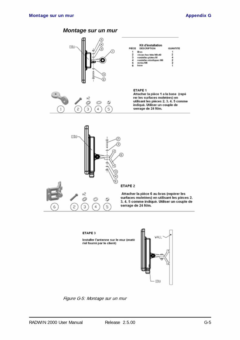
Montage sur un mur Appendix G
RADWIN 2000 User Manual Release 2.5.00 G-5
Montage sur un mur
Figure G-5: Montage sur un mur

Montage d'une antenne externe Appendix G
RADWIN 2000 User Manual Release 2.5.00 G-6
Montage d'une antenne externeL'antenne externe optionnelle peut être montée sur un pylône.
Contenu du kit de montage d'une antenne externeLe kit de montage d'une antenne externe comprend les pièces suivantes
• Douze rondelles plates
• Huit rondelles élastiques• Huit écrous hex
• Quatre boulons• Un support en U• Un support à pivotement
• Deux courroies de fixation en métal
Pour installer une antenne externe sur un pylône:
1. Attacher le support en U à l'arrière de l'antenne en utilisant quatre ron-delles plates, quatre rondelles élastiques et quatre écrous hex.
2. Attacher le support à pivotement au support en U en utilisant huit ron-delles plates, quatre rondelles élastiques, quatre écrous hex et quatre boulons.
3. Passer les deux courroies de fixation par les fentes verticales dans le sup-port à pivotement.
4. Attacher l'antenne au pylône en utilisant les deux courroies de fixation .
Ajuster l'inclinaison nécessaire en utilisant l'échelle angulaire et serrer tous les boulons et écrous à la position requise.

RADWIN 2000 User Manual Release 2.5.00 Index 1
Index
AAAR 1-4ACS 2-7, 8-26aging time, ODU Bridge Mode 8-16Air Interface 1-12, 1-12
Technical Specifications, general A-1Alarms
Activesummary 9-18
Connector B-3External , specification E-1
AntennasAir rates 2-11Align with beeper 4-13Aligning 4-13
bipolar 4-13Buzzer signals 4-14monopolar 4-15
Cable, grounding 18-1Connecting 4-13Described 1-11Diversity Mode 2-10External 1-11
Mounting 4-7Package Contents 4-5
External, Mounting 17-3MIMO - Diversity settings 2-11MIMO Mode 2-10Single and dual 2-9types 1-8
ApplicationsBroadband Access 1-3, 1-3Cellular Backhaul 1-2Private Networks 1-3WiMAX 1-3
Asymmetric Ethernetand Collocation 2-19and TDM services 2-20Installation 2-18Restrictions 2-19Transmission ratio 2-18, 6-5
Automatic Adaptive Rate, see AAR 1-4Automatic Channel Selection, see ACSAutomatic Repeat Request 1-4
BBackup 8-24backup
ODU replacement 9-21Backup and restore software, ODU 8-24Band
and DFS 20-5available 1-8Changing 20-1defaults 1-8, 20-3license key 1-8
Beepermute 8-25muting and restoring 8-2restore 8-25
Bridge mode,Telnet commands 8-27BRS
Installation 16-1
CChanging link password 2-5Channel, selecting 2-7Clock configuration, TDM 2-27Community Strings
Changing 8-11Editing 8-10Forgotten passwords 8-11MIB D-2Read-Only 8-10Read-Write 8-10Trap 8-10
Configuration Parameters 8-3Configuring
Advanced 8-2, 8-15, 8-17, 8-19Air Interface 8-2Air interface 7-1contact person 8-2Date and Time 8-2Date and time 8-1Ethernet settings 8-1External alarms 8-1
Index

RADWIN 2000 User Manual Release2.5.00 Index 2
Frequency channel 7-1HSS 8-1Security 8-2Security settings 8-1Service parameters 7-1System 8-2System parameters 7-1System settings 8-1TDM MHS status 8-1Tx Power and antenna 8-1View Inventory 8-2
Connecting user equipment 2-7Customer Support 9-22
DDate and time, setting 8-2, 8-13DC Power
terminal pinout B-4DFS 16-1
changing band for 20-5Configuration 16-4FCC/IC DFS Installation Procedure 16-1Link Activation 16-1
EEthernet Ring 13-1
1 + 1 13-6operation 13-2Protection Switching 13-5purpose 13-1setting up, ff 13-7supported topologies 13-4terminology 13-1
Eventscolor codes 9-17log 9-2, 9-9priority 9-17
FFactory settings
revert to 8-1, 8-22, 9-22FEC 2-10, 2-11, A-1, A-1Forward Error Correction, see FEC
GGateway 8-2
Telnet display 8-26GSU A-7
Cascaded Sites 11-3Configuring 11-5Installation 11-4Kit 11-4Preferences 11-12Redundancy 11-3Software Update 11-13Telnet Support 11-12
Transmission Phase 11-3, 11-9Tx Transmission Ratio 11-9use
functionalityscenarios 11-1
GUSand RFP 11-8
HHSS 10-1
and asymmetric allocation<$endtrange 2-19, 10-12
Hardware Installation 10-3IDU-C front panel LEDs 4-11, 10-13ODU/HSS Connection Pinout 10-7, B-1Radio Frame Pattern Table 10-7
HSS Client 10-2Continue Transmission 10-3Disable Transmission 10-3
HSS Master 10-2Hub Site Synchronization, see HSS
IIDU
Aging time 8-16aging time, ODU Bridge Mode 8-16Connecting to ODU 4-12described 1-8IDU-C
Alarm Connector B-3Front panel 1-9, 1-9
Described 4-10LEDs 4-10, 4-11, 5-3
Front panel LEDs for HSSLEDs 4-11, 10-13
Mounting 4-9Power connections 4-12, 4-12
Installing IDU-E and R units 4-8Package Contents 4-4
IDU-CPackage Contents 4-4
IDU-E or IDU-R package contents 4-4Indoor Unit, see IDUInstallation
Menu and Toolbar Functionality 6-3Post Configuration main window 7-13Post Installation main window 2-30see Link, Installation
Installation Mode 8-2, 8-2, 8-17Installing
BRS 16-1Interference
caused by collocated units 10-2Inventory 8-1, 8-11
Displaying 8-8IP address 8-2
Telnet display 8-26
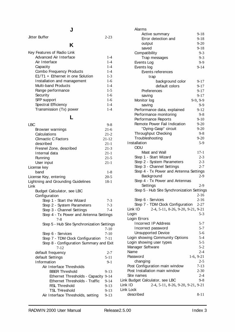
RADWIN 2000 User Manual Release2.5.00 Index 3
JJitter Buffer 2-23
KKey Features of Radio Link
Advanced Air Interface 1-4Air Interface 1-4Capacity 1-4Combo Frequency Products 1-4E1/T1 + Ethernet in one Solution 1-3Installation and management 1-6Multi-band Products 1-4Range performance 1-5Security 1-6SFP support 1-6Spectral Efficiency 1-4Transmission (Tx) power 1-4
LLBC 9-8
Browser warnings 21-6Calculations 21-2Climactic C Factors 21-12described 21-1Fresnel Zone, described 21-3Internal data 21-1Running 21-5User input 21-1
License keyband 1-8
License Key, entering 20-5Lightning and Grounding Guidelines 18-1Link
Budget Calculator, see LBCConfiguration
Step 1 - Start the Wizard 7-3Step 2 - System Parameters 7-3Step 3 - Channel Settings 7-4Step 4 - Tx Power and Antenna Settings
7-8Step 5 - Hub Site Synchronization Settings
7-10Step 6 - Services 7-10Step 7 - TDM Clock Configuration 7-11Step 8 - Configuration Summary and Exit
7-12default frequency 2-7default Settings 5-11Information 9-1
Air Interface ThresholdsBBER Threshold 9-13Ethernet Thresholds - Capacity 9-14Ethernet Thresholds - Traffic 9-14RSL Threshold 9-13TSL THreshold 9-13
Air Interface Thresholds, setting 9-13
AlarmsActive summary 9-18Error detection and 9-18output 9-20saved 9-18
Compatibility 9-3Trap messages 9-3
Events Log 9-9Events log 9-14
Events referencestrap
background color 9-17default colors 9-17
Preferences 9-17saving 9-17
Monitor log 9-9, 9-9saving 9-9
Performance data, explained 9-12Performance monitoring 9-8Performance Reports 9-10Remote Power Fail Indication 9-20
“Dying-Gasp” circuit 9-20Throughput Checking 9-8Troubleshooting 9-20
Installation 5-9ODU
Mast and Wall 17-1Step 1 - Start Wizard 2-3Step 2 - System Parameters 2-3Step 3 - Channel Settings 2-7Step 4 - Tx Power and Antenna Settings
Background 2-9Step 4 - Tx Power and Antennas
Settings 2-9Step 5 - Hub Site Synchronization Settings
2-16Step 6 - Services 2-16Step 7 - TDM Clock Configuration 2-27
Link ID 2-4, 5-11, 8-26, 9-20, 9-21, 9-21Login 5-3Login Errors
Incorrect IP Address 5-7Incorrect password 5-7Unsupported Device 5-6
Login showing Community Options 5-4Login showing user types 5-5Manager Software 5-2Name 2-4Password 1-6, 9-21
changing 2-5Post Configuration main window 7-13Post Installation main window 2-30Site names 2-4
Link Budget Calculator, see LBC 9-8Link ID 2-4, 5-11, 8-26, 9-20, 9-21, 9-21Link Lock
described 8-11

RADWIN 2000 User Manual Release2.5.00 Index 4
Enable 8-12Link Site
Planning 3-1Survey 3-1
Stage 1 - Preliminary Survey 3-2Stage 2 - Physical Survey 3-3
Additional Indoor Site Requirements 3-4
Additional Outdoor Site Requirements3-4
Stage 3 - RF Survey 3-4Login Errors
Incorrect IP Address 5-7Incorrect password 5-7Unsupported Device 5-6
loopbackactivating 9-3deactivate 9-5Local Internal 9-7Remote External 9-6Remote Internal 9-6
MManagement
Addresses 8-5and trap addresses 8-1Configuring the Site 8-2Screen, Telnet 8-28
Manager SoftwareChange log on password 5-8Events Log 6-7Installing 5-1Main window 6-1
Details pane 6-4Toolbar 6-2
main window 5-6Monitor pane 6-5
Ethernet Service 6-5
Radio Interface, 6-5Radio signal strength 6-5
Off-line functionality 5-8Status Bar 6-7
ManualChapters by Audience 1-13Terminology 1-14
MHSdescribed 12-1Installation Procedure 12-1, 12-1Installing 12-3Kit Contents 12-3Maintaining 12-9
IDU Replacement 12-9ODU Replacement 12-10
Port pinout B-2Primary and secondary links 12-2provides 12-2
Switching Logic 12-11System Operation 12-14
MIBAbout D-1Community String D-2Interface API D-1Parameters D-3Private D-2Private Parameters D-6Reference D-1Supported Variables from the RFC 1213 D-4TDM D-3Terminology D-1Traps D-23
Monitored Hot Standby, see MHS
OODU 1-7
Available products 1-8Backup and restore software 8-24Bridge Mode
aging time 8-16Connectorized 1-8Connectorized Antenna 1-7described 1-7, 1-7form factors 1-7Installation, Mast and Wall 17-1Integrated Antenna 1-7, 1-7Mounting Kit 17-1Package Contents 4-3Preloading IP address 19-1Products 1-8Replacing 9-21With integrated antenna 1-11
PPackage, contents of 4-3Password
Link 1-6, 9-21PC, Minimum Requirements 5-1Performance
Monitor 9-2Performance Monitoring, set time interval 9-9PoE
Basic PoE Device 1-9Described 1-9Installing a link using 4-12
PoE device, see PoEPower over Ethernet, see PoEProtection
External Lightning Surge Suppressors 18-3Grounding
Antenna cable 18-1IDUs 18-2ODUs 18-2
Internal ESD Protection circuits 18-7

RADWIN 2000 User Manual Release2.5.00 Index 5
QQoS 23-1
disabling 23-4Overview 23-1setting up, ff 23-2
RRadio Frame Pattern (RFP)
General Considerations 10-9General considerations 10-9With HSS 10-8Without HSS 10-7
Radio LinkAdditional Tools and Materials Required 4-5Air rates 2-11Connecting user equipment 4-13Hardware Installation
External Antennas 4-7Indoor 4-8Lightning protection 4-8Mounting U 4-9ODU 4-7Outdoor 4-7Outdoor connections 4-8Sequence 4-6
Package Contents 4-3IDU 4-4ODU 4-3
Package contentsExternal Antennas 4-5
Radio Outdoor Unit, see ODURegional Notice
French Canadian G-1Replacing an ODU 9-21
SSafety Practices iii-iv, 4-1
Grounding 4-1Preventing overexposure to RF energy 4-1
SecurityLink Lock 8-11
Selecting channel 2-7SFP
device C-1support, described C-1
SiteConfiguration
Backup Filesbackup to 8-24
Backup filesrestore from 8-24
Configuration with Telnet 8-25Dialog
Change Tx Power 8-4Ethernet Properties 8-15
Configuring
Bridge 8-15Maximum information rate 8-19Ports Mode 8-17
Ethernet PropertiesIDU Aging time 8-16
Functions 8-2Inventory 8-8Menu bar 8-2Setting the date and time 8-13View Air Iinterface details 8-3VLAN Settings 8-6
Lost or forgotten VLAN ID 8-8Priority number 8-7VLAN ID 8-7
External Alarm Inputs 8-21Reset site 8-22Reset site to factory defaults 8-22Reset site, preserve current configuration
8-22Security Features 8-9
Community Strings 8-10Editing 8-10Forgotten paswwords 8-11Initial log on defaults 8-10
Default Gateway 8-6IP address 8-6, 8-6Trap Destination 8-6
Software UpgardeMultiple sites 15-3Single Site 15-2
Software Upgrade 15-1Spectrum View
described 5-11using 22-1
TTDM Services
Clock configuration 2-27Evaluation 2-26in Link Budget calculation 21-1Jitter Buffer 2-23Loopbacks 9-3modulation rate 2-23over internet with SFP C-1selection 2-20TDD in MIB D-3Telnet commands 8-26Throughput display 6-6Trap message 9-16
Technical SpecificationsAir Interface, general A-1Configuration A-1EMC A-3, A-5, A-6, A-7, A-7Environmental A-3, A-5Mechanical A-2Power A-2, A-3, A-4, A-4, A-4, A-4, A-4, A-4Radio A-1
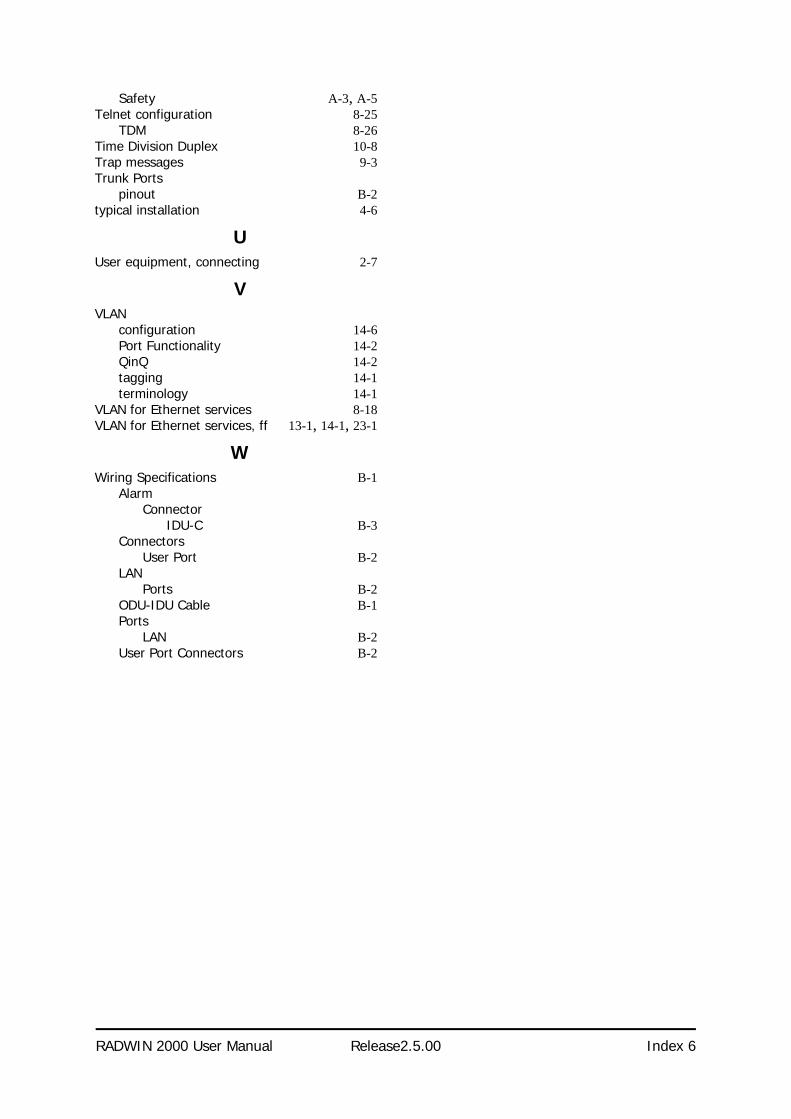
RADWIN 2000 User Manual Release2.5.00 Index 6
Safety A-3, A-5Telnet configuration 8-25
TDM 8-26Time Division Duplex 10-8Trap messages 9-3Trunk Ports
pinout B-2typical installation 4-6
UUser equipment, connecting 2-7
VVLAN
configuration 14-6Port Functionality 14-2QinQ 14-2tagging 14-1terminology 14-1
VLAN for Ethernet services 8-18VLAN for Ethernet services, ff 13-1, 14-1, 23-1
WWiring Specifications B-1
AlarmConnector
IDU-C B-3Connectors
User Port B-2LAN
Ports B-2ODU-IDU Cable B-1Ports
LAN B-2User Port Connectors B-2