user’s guide for gm-counter 5135 - frederiksen user’s guide for gm-counter 5135.3x 20.12.10 ae...
TRANSCRIPT
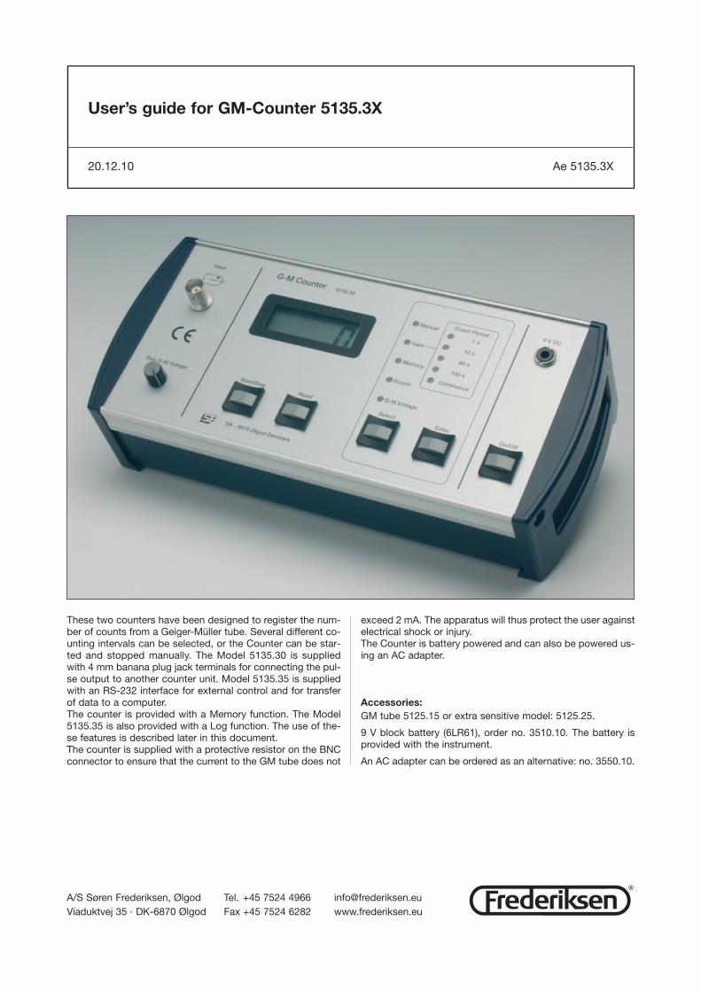
These two counters have been designed to register the num-ber of counts from a Geiger-Müller tube. Several different co-unting intervals can be selected, or the Counter can be star-ted and stopped manually. The Model 5135.30 is suppliedwith 4 mm banana plug jack terminals for connecting the pul-se output to another counter unit. Model 5135.35 is suppliedwith an RS-232 interface for external control and for transferof data to a computer.The counter is provided with a Memory function. The Model5135.35 is also provided with a Log function. The use of the-se features is described later in this document.The counter is supplied with a protective resistor on the BNCconnector to ensure that the current to the GM tube does not
exceed 2 mA. The apparatus will thus protect the user againstelectrical shock or injury.The Counter is battery powered and can also be powered us-ing an AC adapter.
Accessories:GM tube 5125.15 or extra sensitive model: 5125.25.
9 V block battery (6LR61), order no. 3510.10. The battery isprovided with the instrument.
An AC adapter can be ordered as an alternative: no. 3550.10.
User’s guide for GM-Counter 5135.3X
20.12.10 Ae 5135.3X
A/S Søren Frederiksen, Ølgod Tel. +45 7524 4966 [email protected] 35 · DK-6870 Ølgod Fax +45 7524 6282 www.frederiksen.eu
®
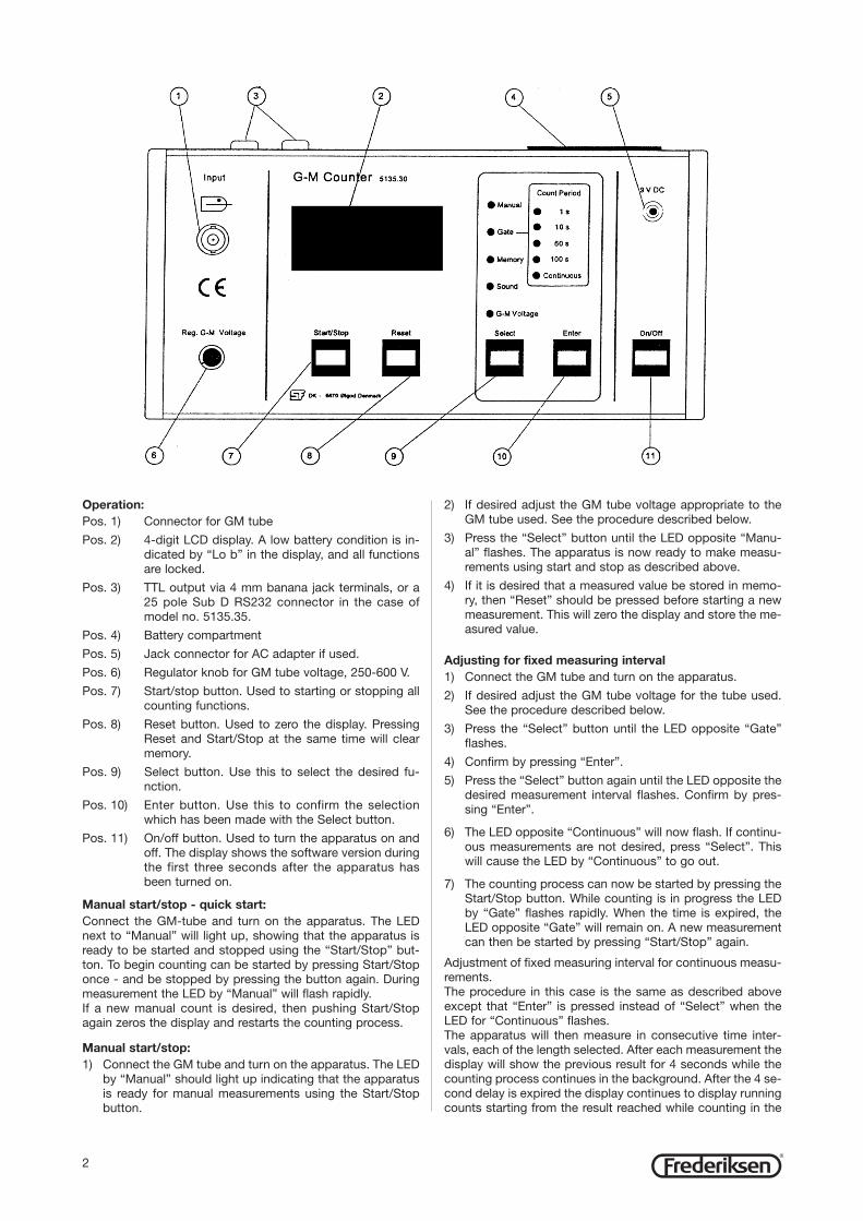
Operation:Pos. 1) Connector for GM tube
Pos. 2) 4-digit LCD display. A low battery condi tion is in-dicated by “Lo b” in the display, and all functionsare locked.
Pos. 3) TTL output via 4 mm banana jack terminals, or a25 pole Sub D RS232 connector in the case ofmodel no. 5135.35.
Pos. 4) Battery compartment
Pos. 5) Jack connector for AC adapter if used.
Pos. 6) Regulator knob for GM tube voltage, 250-600 V.
Pos. 7) Start/stop button. Used to starting or stopping allcounting functions.
Pos. 8) Reset button. Used to zero the display. PressingReset and Start/Stop at the same time will clearmemory.
Pos. 9) Select button. Use this to select the de sired fu-nction.
Pos. 10) Enter button. Use this to confirm the selectionwhich has been made with the Select button.
Pos. 11) On/off button. Used to turn the apparatus on andoff. The display shows the soft ware version duringthe first three seconds after the apparatus hasbeen turned on.
Manual start/stop - quick start:Connect the GM-tube and turn on the apparatus. The LEDnext to “Manual” will light up, showing that the apparatus isready to be started and stopped using the “Start/Stop” but-ton. To begin counting can be started by pressing Start/Stoponce - and be stopped by pressing the button again. During measurement the LED by “Manual” will flash rapidly.If a new manual count is desired, then pushing Start/Stopagain zeros the display and restarts the counting process.
Manual start/stop:1) Connect the GM tube and turn on the apparatus. The LED
by “Manual” should light up indicating that the apparatusis ready for manual measurements using the Start/Stopbutton.
2) If desired adjust the GM tube voltage appro priate to theGM tube used. See the procedure de scribed below.
3) Press the “Select” button until the LED opposite “Manu-al” flashes. The apparatus is now ready to make measu-rements using start and stop as described above.
4) If it is desired that a measured value be stored in memo-ry, then “Reset” should be pressed before starting a newmeasurement. This will zero the display and store the me-asured value.
Adjusting for fixed measuring interval1) Connect the GM tube and turn on the apparatus.
2) If desired adjust the GM tube voltage for the tube used.See the procedure described below.
3) Press the “Select” button until the LED opposite “Gate”flashes.
4) Confirm by pressing “Enter”.
5) Press the “Select” button again until the LED opposite thedesired measurement interval flashes. Confirm by pres-sing “Enter”.
6) The LED opposite “Continuous” will now flash. If continu-ous measurements are not desired, press “Select”. Thiswill cause the LED by “Con tinuous” to go out.
7) The counting process can now be started by pressing theStart/Stop button. While counting is in progress the LEDby “Gate” flashes rapidly. When the time is expired, theLED opposite “Gate” will remain on. A new measurementcan then be started by pressing “Start/Stop” again.
Adjustment of fixed measuring interval for con tinuous measu-rements.The procedure in this case is the same as described aboveexcept that “Enter” is pressed instead of “Select” when theLED for “Continuous” flashes.The apparatus will then measure in consecutive time inter-vals, each of the length selected. After each measurement thedisplay will show the previous result for 4 seconds while thecounting process continues in the background. After the 4 se-cond delay is expired the display continues to display runningcounts starting from the result reached while counting in the
2®
background. All measured values are automatically stored inmemory.
NB: When set up for a counting time interval of 1 second on-ly every other result is displayed, but all values are stored inmemory. When measuring ra dioactive decay, then choose the“Continuous” option.
Adjusting the loud speaker1) Press the “Select” button until the LED opposite “Sound”
flashes. The display now shows the current status of thespeaker: On/Off
2) Press “Enter” to enable toggling between the possiblestates of the speaker. The LED opposite “Sound” will rem-ain on.
3) Now press “Select” to toggle between the two options“On” or “Off”. The state is shown in the display.
4) When the speaker is in the desired state, press “Enter” toconfirm the selection.
Note that the speaker is always “On” by default when the ap-paratus is switched on.
Adjusting the GM-voltage
1) Press the “Select” button until the LED opposite “G.M.Voltage” flashes.
2) Press “Enter” to confirm that the GM voltage is to be ad-justed.
3) The display now shows the current GM voltage, and theLED opposite “G.M. Voltage” remains on.
4) Use the knob (Figure item 6) to adjust the GM voltage. Thevalue can be continuously read from the display.
5) When the desired GM voltage has been adjusted, confirmit by pressing the “Enter” button.
NB: Turning the knob (item 6) will change the GM voltage nomatter what other functions are activated. However, the GMvoltage can only be read off using the procedure describedabove.
Use of the TTL outputModel 5135.30 is supplied with a TTL output for connectingan external counter unit or computer interface.
Use of and read out of memoryThe measured counts value can be transferred to the unit’smemory by pressing “Reset” during manual measurements. Ifcontinuous measurement has been selected, data is transfer-red automatically to memory after each counting interval.
If there is data in memory, then the LED opposite “Memory”will remain on. The LED goes out when memory is empty. TheLED will flash when memory is full.
Data can be read from memory as follows:
1) Press “Select” until the LED opposite “Memory” flashes.
2) Press “Enter” repeatedly to scroll backwards through thesaved data. The most recently stored value is show first,then the next most recent value, etc.
3) When all values in memory have been shown, then “- - -“will be visible in the display.
Note that when reading values from memory, the LED oppo-site the measurement setup when data was taken will light up.
In order to empty (zero) memory press “Start/Stop” and “Re-set” simultaneously.
Using data loggingThis facility is only available in model no. 5135.35.
The datalogger can contain a large number of results includ-ing measuring intervals and a time stamp. If the data logger is“On”, then all the results will be stored under the same con-ditions as when the results are stored in memory. If the data-logger is “Full” then no results will be stored.It is only possible to read the datalogger via the interface, butthe datalogger can be controlled from the front panel. Pres-sing “Enter” and “Select” simultaneously causes the displayto show “LoG” for a moment followed by “on”, “oFF” or“FuLL”. If the display does not show “FuLL” then the state ofthe datalogger can be toggled between “On/Off” by pressing“Select”. The datalogger can be zeroed and turned “oFF” bypressing “Reset” while “on”, “oFF” or “FuLL” is shown in thedisplay.
Use of the RS232 interfaceCounter model 513535 is provided with an RS232 inteface forconnecting it to a PC. Communication can be accomplishedusing the program: Datalyse. It is also possible to use Windows’ Hyperterminal program. The commands needed inthis connection are shown below:
Internal commandsIf a command followed by a “?” is sent to the counter, it willrespond with the help-text for the command whenever rele-vant.
E.g.: ‘b?’ returns the permissible values: ‘300, 1200, 2400,4800, 9600'
A: Activate summer/normal time
‘a0' => summer/normal time not active‘a1" => summer/normal time active
B: Read or adjust baud rate (default 1200 baud)
When this command is used alone, the current baud rate va-lue (in bits per second) is returned. When it is used with awhole number in the set {300,1200,2400,4800,9600}, thenthe baud rate is set to the corresponding value in bps.E.g.: “b1200" changes the baud rate to 1200 bps.
D: Read display
E: Send result or not
When the command is used alone, then the status is retur-ned. “0" means that no results are being sent. When thecommand is used with a number then the status is changedas follows:
‘e0' => results are not sent‘e1' => results are sent
F: Read or set a function
When the command is used alone, then the currently activefunction is returned. When it is used with a number, the acti-ve function is changed as follows:
‘f1' => MANUAL‘f2' => GATE‘f3' => CONTINUE‘f4' => G.M. VOLTAGE (The voltage value is returned provided ‘e’ has been set to ‘1'.)‘f5' => MEMORY
G: Read datalogger
The entire set of logged data is returned. This will take a few
3®
seconds, and the counter can not be used while this is ta-king place. The format of the data is:
Year, month, day, hour, minute, second, measuring interval, valueE.g.:2003,12,08,09,10,13,10,332003,12,08,09,10,23,10,37
H: Zero the datalogger
The contents of the datalogger is zeroed, and the loggingfunction is stopped.
I: Read or set the datalogging function
If this command is used alone, then the current status is ret-uned: “0" means “off”, and “1" means “on”. When datalo-gger memory is full, then the value “2" is returned. When thecommand is used with a number, the datalogger status isset as follows:
‘i0' => turn datalogging off‘i1' => turn datalogging on
K: Read or set time
When the command is used alone the current date and timestring is returned in the format “YYMMDD WHHMiMiS”. Inorder to set the time the following string must be transmit-ted:
k YYMMDD WHHMiMiS
defined as follows:k - the k-commandYY - yearMM - monthDD - dayW - weekday: Monday = 1, Sunday = 7HH - hourMiMi - minuteS - “0" => normal time, “1" => summer time(+ 1 hour)
M: Determines whether the interface is to return extra information from the interface.
‘m0' => no extra messages‘m1' => return extra messages
Q: Choose language returned from interface
When used alone a number is returned indicating the langu-age in use (see below). If the command “q” plus a numberfrom the set {1,2,3,4} is used, then the language is set asfollows:
‘q1' => English‘q2' => French‘q3' => German‘q4' => Danish
R: Zero display and save the result
If a result is ready, it is saved in memory and data logged ifpossible.
S: Start/stop counting
If this commando is used, then the counter is started orstopped, if the function has been set cor rectly:
‘s0' => stop counting‘s1' => start counting
T: Read or set measurement interval
If the command is used alone, then the current measurement interval is returned. If it is used with a numberthen the measurement interval is changed according to thevalue.
‘t1' => 1 second‘t10' => 10 seconds‘t20' => 20 seconds‘t120' => 120 seconds
U: Turn speaker on/off
If the command is used alone, the current speaker status isreturned (“0" for off, “1" for on). If the command is used fora number from the set {0,1,2,3}, then the interface will be setas follows:
‘u0' => speaker off - pause indicator off‘u1' => speaker on - pause indicator off‘u2' => speaker off - pause indicator on‘u3' => speaker on - pause indicator on
V: Version number return
E.g.: “GM counter English version 1.0094SIN 943001".
W: Read memory contents
The current memory contents are returned. If memory isempty, only an <EOF> (end of file) character is returned. Ea-ch line returned consists of measuring time (“0" means MA-NUAL) and the value. the first line which is returned is thecontent of the first storage location.
E.g.: 0, 35 <CR>. 10, 37 <CR><EOF>
Z: Zero memory
Memory will be zeroed.?: Returns a list of all interface commands.
Maintenance:The apparatus does not require special mainten ance. Howe-ver, if the apparatus will not be used for a period of time, it iswise to remove the battery to avoid damage from battery cor-rosion.
Technical specifications:Supply voltage: 9 VDC.Current drain: 35 mA.Power consumption: 315 mW.GM tube voltage: 250-600 VDC, -10%/+5%.
Counting intervals:1 second10 seconds60 seconds100 secondscontinuous/manual
Display: 4 digit LCDMemory: 50 measurementsDatalogger: 250 measurements (Ver. 5135.35 only)
Output:TTL output (Model 5135.30)RS232 output (Model 5135.35)Size: 220 x 108 x 60 mmMass: 0,82 kg
Accessories:In order to connect a Frederiksen A/S GM detector with aDIN-connector to the Counter use adapter no. 5125.80.
Serial cable 25 pin sub-D at PC: Item no. 1123.20.
Serial cable 9 pin sub-D at PC: Item no. 1123.05.
Datalyse software for recording data from this apparatus:3935.16.
This manual may be copied for use internally on the site where the instrument belongs. Alternatively extra manualscan be downloaded from our web site.
4®