user manual of ds-1000ki network keyboard v1.2.2 - hikvision
TRANSCRIPT

DS-1000KI Network Keyboard
User Manual
(Version 1.2.2)

DS-1000KI Keyboard User Manual
Copyright © 2005. All rights reserved. Page 1
Thanks a lot for purchasing our product. If there is any question, please feel free to
contact us.
This manual may have something inaccurate in technology, unsuited with the
product’s functions and operations or the misprints. The manual’s contents will be
changed with the enhanced functions of the product, as well as give the regular advance
or renew the product and procedure in this manual. The renewed contents will be added
in the new edition of this manual and no separate notice will be given.

DS-1000KI Keyboard User Manual
Copyright © 2005. All rights reserved. Page 2
Index
Chapter1 Features of DS-1000KI ..................................................... 3
1.1 Main Features ................................................................................................................. 3
1.2 Sketch of DS-1000KI ..................................................................................................... 5
1.3 Rear Board Description .................................................................................................. 7
1.4 Keyboard Connection ..................................................................................................... 8
Chapter2 Keyboard Operation ......................................................... 9
2.1 Enter into keyboard system ............................................................................................. 9
2.2 Keyboard Configuration ............................................................................................... 11
2.2.1 System Configuration ................................................................................................................. 11
2.2.2 User Configuration ..................................................................................................................... 14
2.2.3 Defense Configuration............................................................................................................. 20
2.3 Control DVR ................................................................................................................ 22
2.3.1 Login DVR ................................................................................................................................ 22
2.3.2 DVR Configuration .................................................................................................................... 24
2.3.2 Video playback .......................................................................................................................... 25
2.3.3 Manual Video Recording ............................................................................................................ 27
2.3.4 PTZ control ................................................................................................................................ 28
2.3.5 Preview...................................................................................................................................... 30
2.3.6 Alarm handling .......................................................................................................................... 31
2.4 Other Information ......................................................................................................... 33
2.4.1 Keyboard lock ............................................................................................................................ 33
2.5 Upgrade Keyboard Firmware ........................................................................................ 34
2.5.1 FTP Server Setup ....................................................................................................................... 34
2.5.2 Upgrade Firmware ..................................................................................................................... 37
Appendix A: Specification ................................................................. 38
Appendix B: Troubleshooting .......................................................... 39
Appendix C: Notes .............................................................................. 40

DS-1000KI Keyboard User Manual
Copyright © 2005. All rights reserved. Page 3
Chapter1 Features of DS-1000KI
1.1 Main Features
Support DVR cascade. One DS-1000KI keyboard can maximum control 99
DVR units via network. If you use RS485 bus mode, one keyboard can
maximum control 32 DVR units.
DS-1000KI Keyboard has two liquid crystal screens with the left one showing
the controlling and configuring menu respectively. Press the key 【Menu】for
less than 2 seconds and enter into the controlling menu, while press【Menu】for
more than 2 seconds and enter into the keyboard configuring menu. The right
one shows the information including the user information, the present login
state, alarm information etc.
DS-1000KI has two communication modes: Network mode and RS485 bus
mode. You can use either of them to control DVR.
DS-1000KI keyboard users are divided into administrator and operator.
Administrator can operate both the controlling and configuring menu while the
operator can only operate the controlling menu.
DS-1000KI has the function to lock keyboard. Press【 】key to lock the
keyboard, and only input the correct password to unlock it.
DS-1000KI controlling menu can carry out DVR configuration, video playback,
manual record, PTZ control, DVR local preview and other functions. Both the
administrator and operator can control them.
DS-1000KI configuring menu can set up keyboard IP address, user ID number,
keyboard communication mode, keyboard password management etc. This part
is only controlled by the administrator.
DS-1000KI can control the different DVR units. Before operating DVR, enter
the configuring menu, in the “SysCfg” menu, select the keyboard control mode
(either network mode or RS485 bus mode). In the “UserCfg” menu, create one
new user, input the user ID, then input the information of the DVR including
DVR user name, password, DEV ID, DVR IP etc. After setting up the user
information, press the key【ID】and input the correct user ID, you can login and
operate the corresponding DVR.
DS-1000KI network keyboard is equipped with the joystick. You can use it to
control PTZ easily.
DS-1000KI network keyboard could receive the alarm information of DVR.
Before being permitted, it should set up to receive the alarm. In the alarm
configuration of the keyboard configuring menu, set up the information on
permitting to receive the alarm. Then, by choosing the alarm handling in the
keyboard controlling menu: set “Arm” to receive the alarm; set “Disarm” not to
receive the alarm. Meanwhile, the keyboard can receive the alarm information

DS-1000KI Keyboard User Manual
Copyright © 2005. All rights reserved. Page 4
of 10 DVR at most.
DS-1000KI network keyboard has four alarm outputs and can set up or clear the alarm
output by operating the alarm handling in the controlling menu.
Note: If you use DS-1000KI network keyboard to control DS-8000 series DVR, the
firmware of DVR must be version1.4 above.

DS-1000KI Keyboard User Manual
Copyright © 2005. All rights reserved. Page 5
1.2 Sketch of DS-1000KI
Fig 1.1.1
1------ Menu area: Show the keyboard menu;
2------【Menu】: Menu key. Press it more than 2 seconds, the menu area will display the
keyboard menu, otherwise the menu area will display the controlling menu;
3------ Information Display area: Display the input information, communication mode, DVR
information, alarm information, etc.
4------【ID】: The user code name. Use it to select DVR to control.
5------【Zoom】: Zoom function in PTZ control mode.
6------【Focus】: Focus function in PTZ control mode.
7------【Iris】: Iris function in PTZ control mode.
8------ Joystick: Control Pan/Tilt in PTZ control mode.
9------【 】: The key to choose the left keyboard menu.
10-----【 】: The key to choose the right keyboard menu.
11----【Cam】: Camera ID number (Corresponding the DVR channel number).
12----【0】~【9】: Number and character keys.
13----【Enter】: Confirmation key.
14----【Mon】: Monitor ID key (Reserved).
15---- Lamps: Ready,Status,Link,Tx/Rx,Com,Alarm,Power.
16----【Del】: Delete key.
17----【*】: Input key to choose uppercase character, lowercase character or number.

DS-1000KI Keyboard User Manual
Copyright © 2005. All rights reserved. Page 6
18----【Shot】: The key to adjust the PTZ preset.
19----【Freeze】: Reserved.
20----【▲】: Page Up key in the information display area. When you input IP address, you can
use it as delete key.
21----【▼】: Page Down key in the information area. When you input IP address, you can use it
as space key.
22----【 】: Keyboard lock key.

DS-1000KI Keyboard User Manual
Copyright © 2005. All rights reserved. Page 7
1.3 Rear Board Description
Fig 1.2.1
1------ Dial Switches. The factory default values are “on on off off off off off off
(11000000)”.
From the picture we can see the dial switch consists of 8 sub-switches. Now the function of
each sub-switch is following:
Switch 1: When in “on”, PORT A full-duplex 485 is changed into half-duplex 485. It
must be used together with Switch 2.
Switch 2: When in “on”, PORT A full-duplex 485 is changed into half-duplex 485. It
must be uses together with Switch 1.
Switch 3: When in “on”, PORT A R+, R- add the matching resistance of 120Ω .
Switch 4: When in “on”, PORT A T+, T- add the matching resistance of 120Ω .
Switch 5: When in “on”, PORT B D+, D- add the matching resistance of 120Ω
Switch 6: “off”. Reserved.
Switch 7: “off”. Reserved.
Switch 8: “off”. Reserved.
2------ RS485 BUS PORT A ( full-duplex mode SW = 00000000, half-duplex mode SW =
11000000), connecting with KEYBOARD port of DVR.
3------ RS485 BUS PORT B.
4------ RS232 Interface (RJ45).
5------ Network Interface (RJ45).
6------ Alarm output interface.
4 kinds of switches (dry nodes) will output the alarm information. With A and B as a group,
they will turn off when there is an alarm. Otherwise, they will turn on.
7------ 5V DC Socket.

DS-1000KI Keyboard User Manual
Copyright © 2005. All rights reserved. Page 8
1.4 Keyboard Connection
1.4.1 Network connection
If you use keyboard network work mode, just use one network cable to connect keyboard UTP
port with network switch or hub. In keyboard “SysCfg” menu, setup one IP address for the keyboard
and select “Net” mode. Please refer to chapter2.2 for detail configuration.
1.4.2 RS-485 connection
If you use keyboard RS-485 bus work bus. On the keyboard rear panel, Port A has R+, R- pins.
On DVR rear panel, there are two RJ45 keyboard interface. You can select one to connect keyboard,
and the other one for DVR cascade. The DVR RJ45 pin definition is following:
DVR keyboard RJ45 interface
Pin definition
To make the connect cable according the follows. As to left point of RJ45 head, 1st and 2
nd
cables are the anode and cathode line for sending, 3rd
and 4th cables are the anode and cathode line
for receiving, 7 is the shared grounding line:
You can connect DS-1000KI Port A R+ R- pins with DVR keyboard interface Pin3 and Pin4,
shown as following:
DS-1000KI
DVR KB
In keyboard “SysCfg” menu, select “Bus” control mode.
R+
R-
Port A
T+ (Pin1)
T- (Pin2)
R+ (Pin3)
R- (Pin4)

DS-1000KI Keyboard User Manual
Copyright © 2005. All rights reserved. Page 9
Chapter2 Keyboard Operation
2.1 Enter into keyboard system
When DS-1000KI network keyboard is in power, the menu screen will show the
following information:
Fig 2.1.1
When “Password” appears on the information screen, input the password (The
default administrator password of DS-1000KI keyboard is 111 and the common
password is 222) and enter into the system operation by pressing the key【Enter】, as
shown following:

DS-1000KI Keyboard User Manual
Copyright © 2005. All rights reserved. Page 10
Fig 2.1.2
Note: DS-1000KI keyboard can control DVR by either network mode or RS485 bus
mode. Here we just describe the usage of network mode. It is the same for RS485 bus
mode.

DS-1000KI Keyboard User Manual
Copyright © 2005. All rights reserved. Page 11
2.2 Keyboard Configuration
Before controlling DVR, you should first configure DS-1000KI net keyboard
including system configuration, user configuration and defense configuration. Press the
key【Menu】for more than 2 seconds, you will enter into the keyboard configuration (the
administrator password is needed to login), as shown in Fig 2.1.1
Fig 2.2.1 Keyboard Configuration
2.2.1 System Configuration
After entering into the configuration interface, we could see three corresponding
menu items named “SysCfg” (Keyboard System Configuration), “UserCfg” (User
Configuration) and “ArmCfg” (Defense Configuration) on the menu screen. Press
“SysCfg” and enter into the system configuration interface, as shown in Fig 2.2.2. In
this configuration menu, you can setup all detail keyboard parameters such as Keyboard
IP, Keyboard ID, port number, super password, operator password and controlling
modes. Each parameter setting is shown below:

DS-1000KI Keyboard User Manual
Copyright © 2005. All rights reserved. Page 12
Fig 2.2.2 Keyboard System Configuration
Prev.: Previous menu.
IP Addr: IP address of DS-1000KI network keyboard. Press【1】to modify it
while press【2】to confirm it as shown in Fig 2.2.3-1.
KBD ID: Keyboard number. Input the keyboard number with the numeral keys
and press【Enter】to confirm it as shown in Fig 2.2.3-2
MaskIP: The sub net IP of DS-1000KI network keyboard. The default factory
value is 255.255.255.0. Press【2】to confirm it. Press【1】to modify it and press
【Enter】to confirm the new mask IP as shown in Fig 2.2.3-3
Port: The network port. Default factory value is 8000. Press【2】to confirm it.
Press【1】to modify it and press【Enter】to confirm the new port number as
shown in Fig 2.2.3-4.
Gateway: The gateway IP address of the keyboard.
SupPwd: The password of the administrator. The default factory value is 111.
Input the new password with the numeral keys and press【Enter】to confirm it as
shown in Fig 2.2.3-5 and Fig 2.2.3-6.
Password: The password of the operator. The default factory value is 222. The
setup usage is the same as the super password.
CtrlMod: You can select either RS485 BUS mode or network mode to control
DVR. Press【1】to choose the bus mode and press【2】to choose the net mode
as shown in Fig.2.2.3-7.
Reboot: Reboot keyboard.
Upgrade: You can upgrade the firmware of DS-1000KI keyboard via network.
In the upgrade menu, input the FTP server IP. Then keyboard will connect with
the FTP server and download the firmware via network. Please refer to FTP
server user manual.

DS-1000KI Keyboard User Manual
Copyright © 2005. All rights reserved. Page 13
Fig 2.2.3 Parameter Settings

DS-1000KI Keyboard User Manual
Copyright © 2005. All rights reserved. Page 14
2.2.2 User Configuration
In the “User Configuration” menu, you can setup many users. Each user can only
control one DVR. After you create the relationship between the user and DVR, you can
input the username to login the corresponding DVR and control DVR using the
keyboard. In the “User Configuration” menu, you can add, delete, modify and query the
users and related DVRs.
Fig 2.2.4 User Configuration
New User
For example, if you want to control DVR with IP address of 192.0.1.99 by DS-1000KI
network keyboard. First, you should create one new user. Choose “New” item in the
user configuration menu, you will enter into new user input menu as shown in Fig 2.2.5.
You can input the new user name. Press【*】to shift the input method as shown in Fig
2.2.5.

DS-1000KI Keyboard User Manual
Copyright © 2005. All rights reserved. Page 15
Fig 2.2.5 Input Methods of DS-1000KI
For example, here I input “01” as the user name and press【Enter】to confirm it as
shown in Fig 2.2.6-1.
Fig 2.2.6
Then, choose the device type (“1.DVR” as shown in Fig 2.2.6-2), press【1】to

DS-1000KI Keyboard User Manual
Copyright © 2005. All rights reserved. Page 16
choose “DVR” and input the user name, password of the DVR. The keyboard must use
this username and password to login the DVR. For example, the default user name of
DVR 192.0.1.99 is “admin” and the default password of the DVR is “12345”. Here we
also input the same username and password as shown in Fig 2.2.6-3, 2.2.6-4.
For Dev ID and Dev Port as shown in Fig 2.2.6-5, Fig 2.2.6-7, you must input the
same Dev ID and port number as DVR has. In the “Display” menu of DVR, you can
find out the Dev ID. The default ID of DVR is “88”. Here we input “01” because the
Dev ID of DVR (192.0.1.99) is 01.
Note: If you use RS485 Bus control mode, please make sure that each DVR has
different Dev ID so that the user can login the corresponding DVR.
Finally, input DVR IP address of “192.0.1.99”, then save the configuration. You
can create other new users with the above steps.
Modify
In case of revising some users, here we use the above example to explain the
operation. We know that the user of “01” can control DVR with “192.0.1.99” IP address.
Now, we will change it into controlling DVR with “192.0.1.9” IP address. The detailed
operation is following:
1. Input user name: In the user configuration menu as shown in Fig 2.2.4, choose
the “Modify” menu item. In the information display area screen, input the user name of
“01” and press【Enter】to confirm it as shown in Fig 2.2.7.
Fig 2.2.7 Input User Name
2. Modify Device Type: In the information display screen as shown in Fig 2.2.8,
we could see the original configuration of user “01” is DVR. If the new configuration is
also DVR, press【2】; If you want to change into other device type, press【1】to choose
new device type (At present, only DVR device type can be selected).
Fig 2.2.8 Change device type
3. Modify Device Username: Modify device username according to the indication.

DS-1000KI Keyboard User Manual
Copyright © 2005. All rights reserved. Page 17
If there is no need to revise, press【2】to confirm it and enter the next operation as shown
in Fig 2.2.9.
Fig 2.2.9 Modify Device Username
4. Modify Device Password: See Fig 2.2.10.
Fig 2.2.10 Modify Device Password
5. Modify Device ID: See Fig 2.2.11.
Fig 2.2.11 Modify Device ID
6. Modify Device IP address: See Fig 2.2.12
Fig 2.2.12 Modify Device IP Address
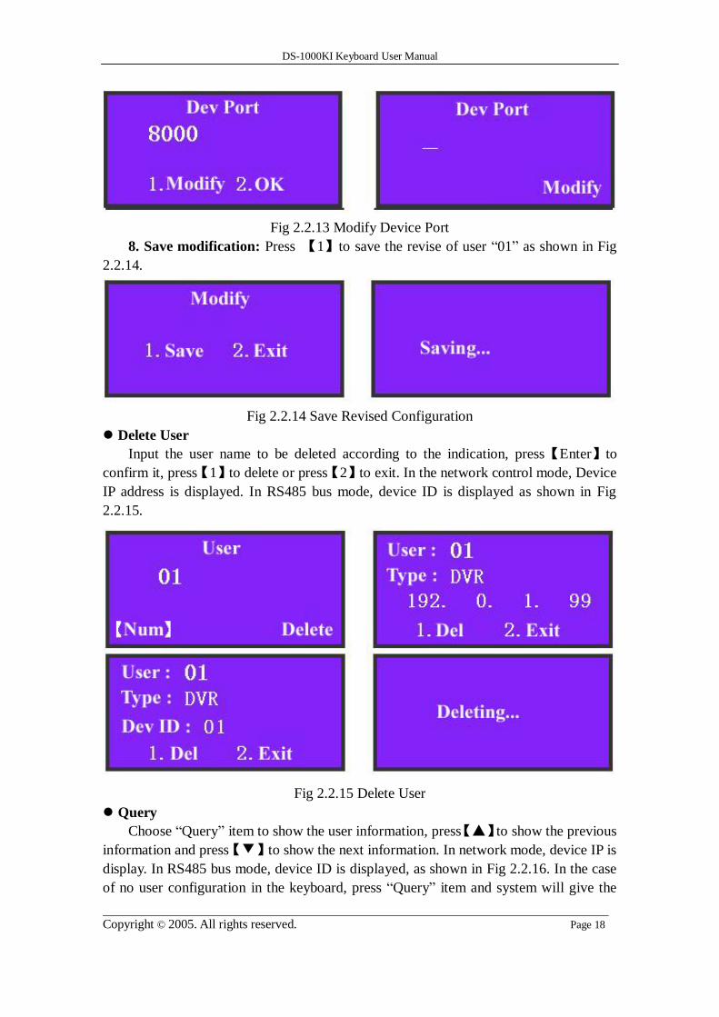
7. Modify Device Port: See Fig 2.2.13.
DS-1000KI Keyboard User Manual
Copyright © 2005. All rights reserved. Page 18
Fig 2.2.13 Modify Device Port
8. Save modification: Press 【1】to save the revise of user “01” as shown in Fig
2.2.14.
Fig 2.2.14 Save Revised Configuration
Delete User
Input the user name to be deleted according to the indication, press【Enter】to
confirm it, press【1】to delete or press【2】to exit. In the network control mode, Device
IP address is displayed. In RS485 bus mode, device ID is displayed as shown in Fig
2.2.15.
Fig 2.2.15 Delete User
Query
Choose “Query” item to show the user information, press【▲】to show the previous
information and press【▼】to show the next information. In network mode, device IP is
display. In RS485 bus mode, device ID is displayed, as shown in Fig 2.2.16. In the case
of no user configuration in the keyboard, press “Query” item and system will give the

DS-1000KI Keyboard User Manual
Copyright © 2005. All rights reserved. Page 19
suggestion of “Not Existing User”.
Fig 2.2.16 Query User Information
Delete all
If we need to delete all the users, press “DelAll” item and press【1】to confirm it so
that all the built users will be deleted. Press【2】to exit and return to the previous menu.
It’s interface is shown in Fig 2.2.17.
Fig 2.2.17 Delete All Users

DS-1000KI Keyboard User Manual
Copyright © 2005. All rights reserved. Page 20
2.2.3 Defense Configuration
Choose “ArmCfg” item, if there is no defense setting, the information display area
will be shown as Fig 2.2.18-1. Press【1】to defense or press【2】to exit and enter into the
next user. If there is defense setting, the interface will be displayed as Fig 2.2.18-2.
Press【1】to remove the defense or press【2】to enter into the next user.
For each user, the operation of setting up or removing the defense is the same. After
you finish for all users, press【2】to exit “Defense Configuration” as shown in Fig
2.2.18-3 and Fig 2.2.18-4.
Fig 2.2.18 Defense Configuration
After you finish the defense configuration, press [Menu] button of the keyboard to
enter into DVR control menu as following:

DS-1000KI Keyboard User Manual
Copyright © 2005. All rights reserved. Page 21
Fig 2.2.19
Choose “DealAlm” item and enter into alarm response menu as shown in Fig
2.2.20:
Fig 2.2.20 Keyboard Response DVR Alarm
In the defense configuration as shown in Fig 2.2.18, if you enable arm function and
in the alarm response menu shown in Fig 2.2.20, if you choose “Arm” item, then
DS-1000KI keyboard will listen and receive alarm information from DVR. Please note
in the DVR menu, enable the “Upload to center” option so that DVR will send alarm
information to the keyboard. When the keyboard receives the alarm information from
DVR, keyboard will display it in the information display area. There are 4 alarm output
ports in the rear panel of the keyboard, you can choose alarm output items to trigger the
corresponding alarm output. Please refer to section 2.3.6.
At present, the keyboard can manage alarm information from 10 DVRs.

DS-1000KI Keyboard User Manual
Copyright © 2005. All rights reserved. Page 22
2.3 Control DVR
After finishing the user configuration, we can choose the user name to control the
relevant DVR.
Please note, at one time you can only select DVR front panel or keyboard to
control DVR.
2.3.1 Login DVR
Press【ID】button, you will enter into the following menu.
Fig 2.3.1 Input User Name
If the DVR is in local preview status (no one is controlling DVR using either DVR
front panel or other keyboards) and connection is OK, after you enter into the user and
press [Enter] button, you will login the corresponding DVR as shown in Fig 2.3.2.
You can press【*】to shift the inputting method like numeral【Num】, lower case
【Lower】, upper case【Upper】.

DS-1000KI Keyboard User Manual
Copyright © 2005. All rights reserved. Page 23
Fig 2.3.2 Login DVR
After you input the user and login the corresponding DVR, in the network mode,
keyboard will display the DVR IP address while in the RS485 bus mode, will display
DVR ID number.

DS-1000KI Keyboard User Manual
Copyright © 2005. All rights reserved. Page 24
2.3.2 DVR Configuration
Choose “DVRCfg” item and show the information as in Fig 2.3.3
Fig 2.3.3 DVR Configuration Menu
The items in the keyboard controlling menu are the same as those of DVR local
front panel. We could see the menu below on the menu screen and describe them
respectively below:
【Prev.】: Return to the previous menu of the keyboard.
【Power】: The power switch of DVR.
【Menu】: Shift the operating interface of DVR local menu and can also control the
wiper in the PTZ mode.
【A】: Shift to different input methods such as numeral, lower case, upper case, and
symbol characters.
【Esc】: Cancel the present operation and return to the previous DVR menu.
【Edit】: In the edition mode, delete the wrong character. In preview mode, shift the
picture preview channel.
【Info】: Show the DVR information. (Reserved)
【Voice】: Start a voice talk function. (Reserved)
【F1】: Turn on or off the sound when playback. Open or close the light in the PTZ
mode (Reserved).
【F2】: Control the auxiliary functions in the PTZ mode (Reserved).
【Up】: Choose the items in the menu.
【Down】: Choose the items in the menu.
【Left】: Shift the items in the menu.
【Right】: Shift the items in the menu.

DS-1000KI Keyboard User Manual
Copyright © 2005. All rights reserved. Page 25
2.3.2 Video playback
Choose “Playback” item as shown in Fig 2.3.2 and enter into playback menu as
shown in Fig 2.3.4.
Fig 2.3.4 Playback
Choose “Begin Time” and “End Time”, input the start and end time and press
【Enter】. DVR will search and list the matched files in DVR local playback menu.
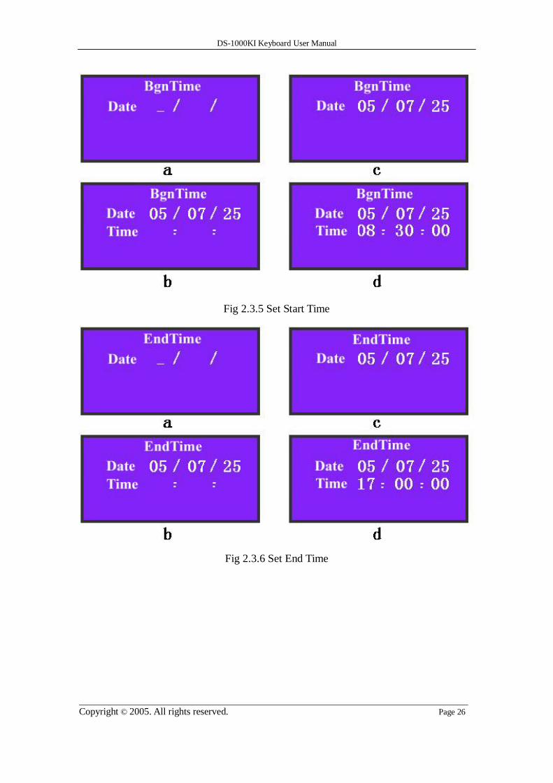
Choose “BgnTime” item and show the information as shown in Fig 2.3.5-a. Input
“Year”, “Month” and “Date” respectively as shown in Fig 2.3.5-c, press【Enter】to
confirm it and enter the time set, input “Hour, “Minute” and “Second” respectively.
Please note the above information must be input into two numbers. For example, in the
case of inputting 8:5:5am, July 25th, 2005, the inputting format is “05/07/25” and
“08/05/05” not “5/7/25” and “8/5/5”. Similarly, choose “End Time” and set the end time.
Press【Enter】 to search and list the matched video files.
Return DVR configuration menu as shown in Fig 2.2.3, use【Up】【Down】button to
select one file and press【Enter】, DVR will start playing the selected file.
In the playback menu of keyboard, you can choose the relevant items to playback,
pause, stop, fast play, slow play, forward, backward and the volume. If you press “Fast”
or “Slow”, the playback speed will increase or reduce one time. The maximum speed is
16 times while the minimum speed is 1/16 time. Press “Forward” and “Backward” to go
forward or draw back for about 30 seconds. Press the numeral keys or【Cam】to change
the channel.
DS-1000KI Keyboard User Manual
Copyright © 2005. All rights reserved. Page 26
Fig 2.3.5 Set Start Time
Fig 2.3.6 Set End Time

DS-1000KI Keyboard User Manual
Copyright © 2005. All rights reserved. Page 27
2.3.3 Manual Video Recording
Choose “Record” as shown in Fig 2.3.2 and display the information as shown in Fig
2.3.7. Choose the relevant items to control the manual video recording function of DVR
including starting and stopping recording of one channel or all channels. Press numeral
keys or【Cam】 to change the channels. Choose “Prev.” to return the previous
controlling menu of the keyboard.
Fig 2.3.7 Manual Recording
DS-1000KI Keyboard User Manual
Copyright © 2005. All rights reserved. Page 28
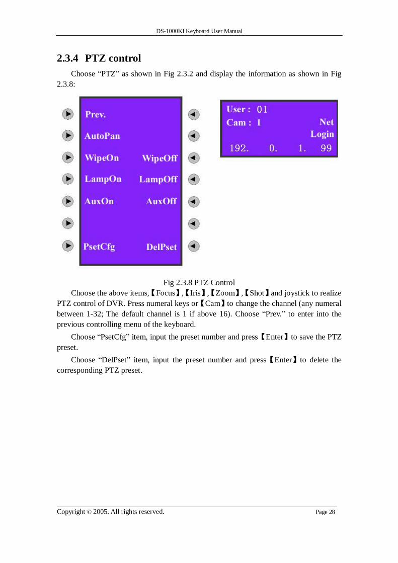
2.3.4 PTZ control
Choose “PTZ” as shown in Fig 2.3.2 and display the information as shown in Fig
2.3.8:
Fig 2.3.8 PTZ Control
Choose the above items,【Focus】,【Iris】,【Zoom】,【Shot】and joystick to realize
PTZ control of DVR. Press numeral keys or【Cam】to change the channel (any numeral
between 1-32; The default channel is 1 if above 16). Choose “Prev.” to enter into the
previous controlling menu of the keyboard.
Choose “PsetCfg” item, input the preset number and press【Enter】to save the PTZ
preset.
Choose “DelPset” item, input the preset number and press【Enter】to delete the
corresponding PTZ preset.

DS-1000KI Keyboard User Manual
Copyright © 2005. All rights reserved. Page 29
Fig 2.3.9 PTZ Preset Configuration
Note: The preset function needs PTZ support.

DS-1000KI Keyboard User Manual
Copyright © 2005. All rights reserved. Page 30
2.3.5 Preview
Choose “Preview” as shown in Fig 2.3.2 and enter into the preview control menu as
shown in Fig 2.3.10.
Fig 2.3.10 Preview
Choose the above items and realize DVR local preview shift.
Select preview mode:
There are 4 preview modes: 1 Screen, 4 Screen, 9 Screen and 16 Screen. You can
press the corresponding key as shown in Fig 2.3.10 to select one preview mode.
Switch preview camera:
In the one screen preview mode, press【Cam】or any numeral key, input the
channel number in the information display area (At present it can be input any
numerals between 1-32. The default channel is 1 if the input is bigger than16), then
press【Enter】to shift the previewing web page on the different channels.
Start preview cycle:
Choose “StarCyl”, DVR will start cycle previewing according to the preview
sequence and switch interval. Please note the switch interval time must not be set as
“Never”.
Stop preview cycle:
If there is no need to cycle preview between channels, choose “StopCyl” and choose “Prev.” to
exit into the control menu of the keyboard.

DS-1000KI Keyboard User Manual
Copyright © 2005. All rights reserved. Page 31
2.3.6 Alarm handling
Choose “DealAlm” as shown in Fig2.3.2 and enter into the following alarm
handling control menu:
Fig 2.3.11 Alarm Handling
Choose “Arm” or “Disarm” to start or stop receiving the alarm information sent
from DVR. The alarm information includes view tampering alarm, motion detection
alarm, video loss alarm and external sensor alarm.
Example when the alarm information is received:
Fig 2.3.12 External Sensor Alarm Input
Fig 2.3.12 means all 16 sensors alarm happened.

DS-1000KI Keyboard User Manual
Copyright © 2005. All rights reserved. Page 32
Fig 2.3.13 Video Loss Alarm
Fig 2.3.13 means video lost of the 2nd, 6th and 9th
channels.

DS-1000KI Keyboard User Manual
Copyright © 2005. All rights reserved. Page 33
2.4 Other Information
2.4.1 Keyboard lock
Press【 】key on the keyboard, the keyboard will be locked. If you press any key,
there is a message “Password” as shown in Fig 2.5.1. Input the correct password to
unlock the keyboard. The unlock password is the same as the keyboard login password
(the default factory password is 111 for the administrator and 222 for the operator). You
have to input the password to login again if the keyboard is locked.
Fig 2.5.1 Keyboard Lock/Unlock

DS-1000KI Keyboard User Manual
Copyright © 2005. All rights reserved. Page 34
2.5 Upgrade Keyboard Firmware
You can upgrade DS-1000KI keyboard firmware via network. In keyboard setup menu, enter
into upgrade mode, and input PC IP where keyboard firmware file is placed, keyboard will connect
with PC and download firmware via network.
2.5.1 FTP Server Setup
The FTP server software is run in one PC. You can download FTP server software through
internet. Here we use wftpd32.exe as the example:
1. Run wftpd32.exe (FTP server software).
2. Select “Logging” in the menu,choose Log Options in the sub menu, and give the choice as
following:

DS-1000KI Keyboard User Manual
Copyright © 2005. All rights reserved. Page 35
3. Select “Users/rights” under “Security” menu item. The following dialog box will be
pop-up.
4. Create new user. Click “new user’. New user dialog pops up. Input user name “target”.
Click “OK”.
5. In the password dialog, input password “target” in “New Password” and “Verify
Password” edit box. Click “OK” to save and exit the dialog box.
6. In the “User/Rights Security” Dialog, select “User Name” as “target”. In “Home
Directory” edit box, input the path where the firmware file (digicap) is placed. Then press “Done” to
exit. Here I place keyboard firmware file in folder named “C:\firmware”.

DS-1000KI Keyboard User Manual
Copyright © 2005. All rights reserved. Page 36
7. Next time, you need not setup again, just double click and open “wftpd32.exe” to upgrade the
firmware.

DS-1000KI Keyboard User Manual
Copyright © 2005. All rights reserved. Page 37
2.5.2 Upgrade Firmware
Please make sure that DS-1000KI and PC are in the same sub net. You can use Ping command
to check.
Enter into keyboard system configuration menu as following:
Press “Upgrade” button, input PC IP address, keyboard will connect the PC and try
to download firmware file via network.

DS-1000KI Keyboard User Manual
Copyright © 2005. All rights reserved. Page 38
Appendix A: Specification Control mode RS-485 bus mode (Port A)
Network mode (UTP Port)
Communication interface 1 RJ45 10M/100M UTP network port
1 RJ45 RS-232 port
2 RS-485 port (Port B is reserved)
Bus work mode 1 switch for full-duplex or half-duplex selection
SW = 00000000 is full-duplex mode
SW = 11000000 is half-duplex mode (default)
Relay output 4 output
Power supply DC +5V/6A
Power consumption 6W
Working temperature -10℃--+55℃
Working humidity 10%--90%
Size 360mm*190mm*55mm
Weight 2.4Kg

DS-1000KI Keyboard User Manual
Copyright © 2005. All rights reserved. Page 39
Appendix B: Troubleshooting Description Possible Reasons
Unable to login DVR
Incorrect user name or password to login DVR
Incorrect setup of DVR port number or IP
address
Wrong link between keyboard and DVR
Broken net cable or RS485 bus
Can not receive alarm information No defense is set up for keyboard
Set wrong DVR alarm handling
DVR panel is locked Keyboard operation does not return to the
preview interface
Unable to operate DVR after the
successful login
DVR does not return to the preview interface

DS-1000KI Keyboard User Manual
Copyright © 2005. All rights reserved. Page 40
Appendix C: Notes 1) Place net keyboard in the adequately ventilated space.
2) Net keyboard shall work in the allowed temperature and humidity scope
3) Do not touch LCD screen with hard objects.
4) Do not splash water or other liquid onto the keyboard when using, to avoid
short-circuit or corrosion.