user manual - nexo-sa.com · warnings page 3/17 2 warnings precautions do not open the speaker, do...
TRANSCRIPT
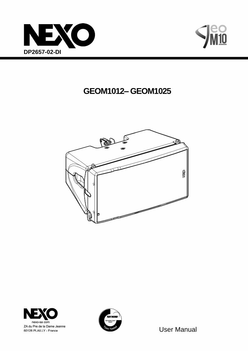
User Manual
DP2657-02-DI
GEOM1012– GEOM1025
Page 2/17 CONTENTS
1 CONTENTS
1 CONTENTS ................................................................................................................................................................. 2
2 WARNINGS ................................................................................................................................................................. 3
3 GEOM10 RIGGING .................................................................................................................................................... 4
4 GEOM10 – ACCESSORIES ....................................................................................................................................... 6
5 DESCRIPTION ........................................................................................................................................................... 9
6 PRESET GEOM10 ................................................................................................................................................... 10
7 ARRAY EQ................................................................................................................................................................. 14
8 MAINTENANCE ....................................................................................................................................................... 15
9 TECHNICAL SPECIFICATIONS ............................................................................................................................ 16
10 USER NOTES ............................................................................................................................................................ 17
EU Conformity declaration
We, NEXO SA ZA DU PRE DE LA DAME JEANNE 60128 PLAILLY – France Declare under our sole responsibility that the product Loudspeaker
Type GEOM10
Serial number On the product
Is in conformity with the provisions of the following 2006/95/CE (Low Voltage Directive) directive including all applicable amendments:
Applied rules and standards: EN ISO 12100, EN 60065
Plailly, February 07th, 2017 Joseph CARCOPINO, R&D Director
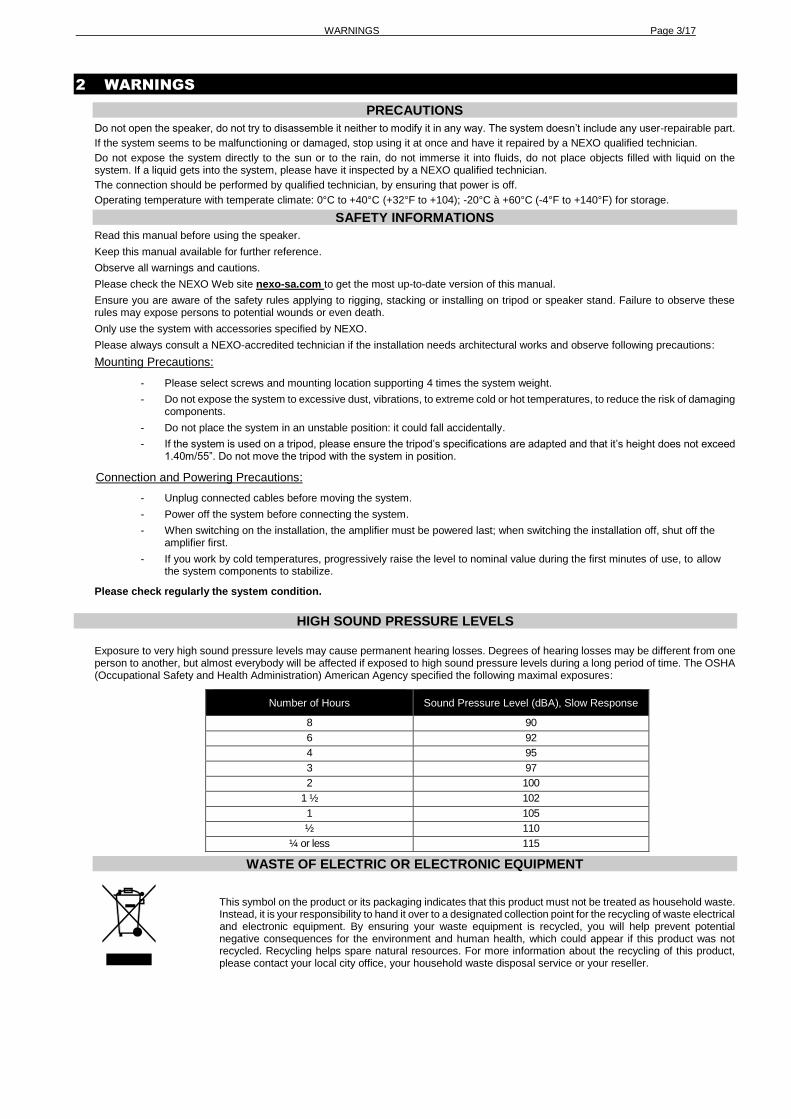
WARNINGS Page 3/17
2 WARNINGS
PRECAUTIONS
Do not open the speaker, do not try to disassemble it neither to modify it in any way. The system doesn’t include any user-repairable part.
If the system seems to be malfunctioning or damaged, stop using it at once and have it repaired by a NEXO qualified technician.
Do not expose the system directly to the sun or to the rain, do not immerse it into fluids, do not place objects filled with liquid on the system. If a liquid gets into the system, please have it inspected by a NEXO qualified technician.
The connection should be performed by qualified technician, by ensuring that power is off.
Operating temperature with temperate climate: 0°C to +40°C (+32°F to +104); -20°C à +60°C (-4°F to +140°F) for storage.
SAFETY INFORMATIONS
Read this manual before using the speaker.
Keep this manual available for further reference.
Observe all warnings and cautions.
Please check the NEXO Web site nexo-sa.com to get the most up-to-date version of this manual.
Ensure you are aware of the safety rules applying to rigging, stacking or installing on tripod or speaker stand. Failure to observe these rules may expose persons to potential wounds or even death.
Only use the system with accessories specified by NEXO.
Please always consult a NEXO-accredited technician if the installation needs architectural works and observe following precautions:
Mounting Precautions:
- Please select screws and mounting location supporting 4 times the system weight.
- Do not expose the system to excessive dust, vibrations, to extreme cold or hot temperatures, to reduce the risk of damaging components.
- Do not place the system in an unstable position: it could fall accidentally.
- If the system is used on a tripod, please ensure the tripod’s specifications are adapted and that it’s height does not exceed 1.40m/55”. Do not move the tripod with the system in position.
Connection and Powering Precautions:
- Unplug connected cables before moving the system.
- Power off the system before connecting the system.
- When switching on the installation, the amplifier must be powered last; when switching the installation off, shut off the amplifier first.
- If you work by cold temperatures, progressively raise the level to nominal value during the first minutes of use, to allow the system components to stabilize.
Please check regularly the system condition.
HIGH SOUND PRESSURE LEVELS
Exposure to very high sound pressure levels may cause permanent hearing losses. Degrees of hearing losses may be different from one person to another, but almost everybody will be affected if exposed to high sound pressure levels during a long period of time. The OSHA (Occupational Safety and Health Administration) American Agency specified the following maximal exposures:
Number of Hours Sound Pressure Level (dBA), Slow Response
8 90
6 92
4 95
3 97
2 100
1 ½ 102
1 105
½ 110
¼ or less 115
WASTE OF ELECTRIC OR ELECTRONIC EQUIPMENT
This symbol on the product or its packaging indicates that this product must not be treated as household waste. Instead, it is your responsibility to hand it over to a designated collection point for the recycling of waste electrical and electronic equipment. By ensuring your waste equipment is recycled, you will help prevent potential negative consequences for the environment and human health, which could appear if this product was not recycled. Recycling helps spare natural resources. For more information about the recycling of this product, please contact your local city office, your household waste disposal service or your reseller.
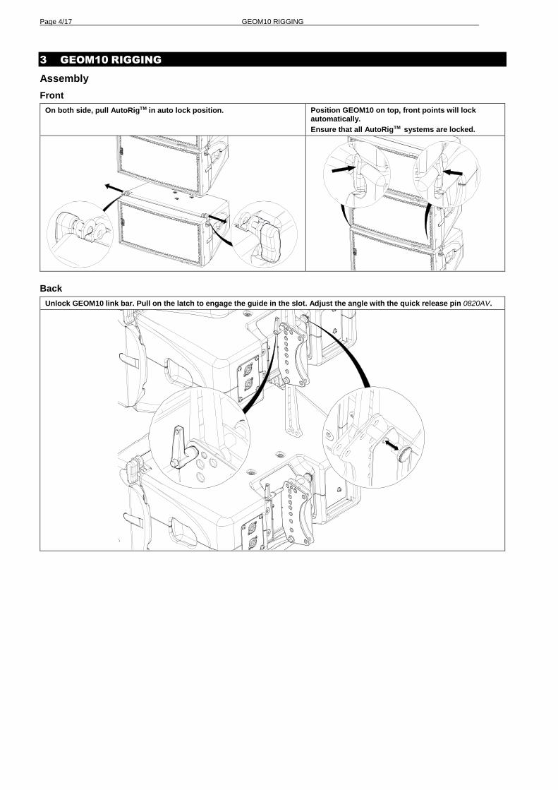
Page 4/17 GEOM10 RIGGING
3 GEOM10 RIGGING
Assembly
Front
On both side, pull AutoRigTM in auto lock position. Position GEOM10 on top, front points will lock automatically.
Ensure that all AutoRigTM systems are locked.
Back
Unlock GEOM10 link bar. Pull on the latch to engage the guide in the slot. Adjust the angle with the quick release pin 0820AV.
GEOM10 RIGGING Page 5/17
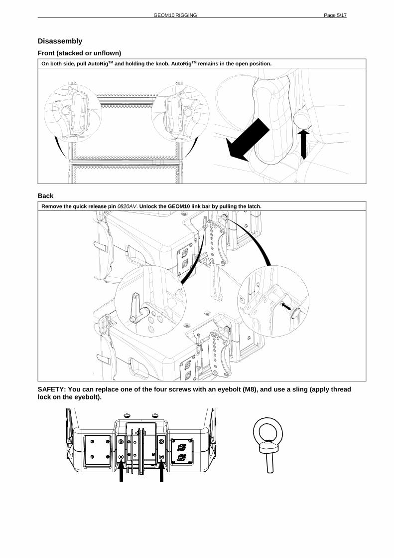
Disassembly
Front (stacked or unflown)
On both side, pull AutoRigTM and holding the knob. AutoRigTM remains in the open position.
Back
Remove the quick release pin 0820AV. Unlock the GEOM10 link bar by pulling the latch.
SAFETY: You can replace one of the four screws with an eyebolt (M8), and use a sling (apply thread lock on the eyebolt).
Page 6/17 GEOM10 – ACCESSORIES
4 GEOM10 – ACCESSORIES
Warnings
All GEOM10 accessories are specifically rated in agreement with structural computations.
Never use other accessories – including push-pins – when assembling GEOM10 cabinets than the ones provided by NEXO: NEXO will decline responsibility over the entire GEOM10 accessory range if any component is purchased from different supplier.
All GEOM10 accessories have been designed so that cabinet are arrayed vertically.
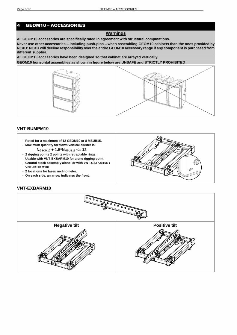
GEOM10 horizontal assemblies as shown in figure below are UNSAFE and STRICTLY PROHIBITED
VNT-BUMPM10
- Rated for a maximum of 12 GEOM10 or 8 MSUB15.
- Maximum quantity for flown vertical cluster is:
NGEOM10 + 1.5*NMSUB15 <= 12
- 2 rigging points 2 points with retractable rings.
- Usable with VNT-EXBARM10 for a one rigging point.
- Ground stack assembly alone, or with VNT-GSTKM10S /
VNT-GSTKM10L.
- 2 locations for laser/ inclinometer.
- On each side, an arrow indicates the front.
VNT-EXBARM10
Negative tilt
Positive tilt
GEOM10 – ACCESSORIES Page 7/17
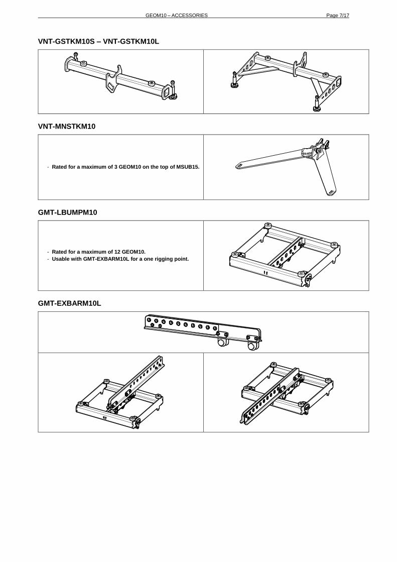
VNT-GSTKM10S – VNT-GSTKM10L
VNT-MNSTKM10
- Rated for a maximum of 3 GEOM10 on the top of MSUB15.
GMT-LBUMPM10
- Rated for a maximum of 12 GEOM10.
- Usable with GMT-EXBARM10L for a one rigging point.
GMT-EXBARM10L

Page 8/17 GEOM10 – ACCESSORIES
GMT-FLGM10
- Pair of flanges for 120°horizontal directivity.
- No tools, magnetic clamp.
GMT-3CASEM10
GMT-6CASEM10

DESCRIPTION Page 9/17
5 DESCRIPTION
- GEOM1012 and GEOM1025 are a compact high-technology line array, 2 way passive, with a 10’’ LF and a 1.4’’
HF.
Without tools, you can change the HF horizontal directivity by adding a pair of magnetic flanges.
- GEOM1012 : 12° vertical dispersion
- GEOM1025 : 25° vertical dispersion
- Versions :
o GEOM1012 : Touring application ; Black
o GEOM1012-PW : Touring application ; White
o GEOM1025 : Touring application ; Black
o GEOM1025-PW : Touring application ; White
o For fixed installations, see user manual GEOM1012-I / GEOM1025-I
- Connectors:
o GEOM1012t/1025t: two NL4 connectors, the 4 pins of the 2 sockets are connected in parallel within the
enclosure.
o GEOM10 use 2+/2-, (1+/1- through).
- Amplification:
o The GEOM10 cabinets MUST be used with a NEXO processor to handle EQ, phase alignment, crossover
and excursion/thermal protection for the system loudspeakers. There are two NEXO processor series
supporting the GEOM10 cabinet: NXAMP (4-channel) amplified processors and DTD processors (stereo +
sub).
o The following table shows the number of GEOM10 usable with each solution.
NXAMP4x1MK2 NXAMP4x1MK2
(bridged) NXAMP4x2MK2 NXAMP4x4
DTD + DTDAMP4x1.3
GEOM10 1 per channel Up to 2 per channel Up to 3 per channel Up to 4 per channel Up to 2 per channel
Recommended
Page 10/17 PRESET GEOM10
6 PRESET GEOM10
Please consult nexo-sa.com for NEXO TD Controllers firmware information.
For the GEOM1012, with or without directivity flanges, the following setups are available:
o Setup for one stand-alone box, with high-pass at 63, 75, 85, 95 or 120 Hz.
o Setup for arrays from 2 to 3 boxes, with high-pass at 63, 75, 85, 95 or 120 Hz.
o Setup for arrays from 4 to 6 boxes, with high-pass at 63, 75, 85, 95 or 120 Hz.
o Setup for arrays from 7 to 12 boxes, with high-pass at 63, 75, 85, 95 or 120Hz.
o Setup for Stack Monitor, with high-pass at 63, 75 or 85 Hz.
For the GEOM1025, with or without directivity flanges, the following setups are available:
o Setup for one stand-alone box, with high-pass at 63, 75, 85, 95 or 120 Hz.
o Setup for 2 to 3 boxes, with high-pass at 63, 75, 85, 95 or 120 Hz.
o Setup for Stack Monitor, with high-pass at 63, 75 or 85 Hz.
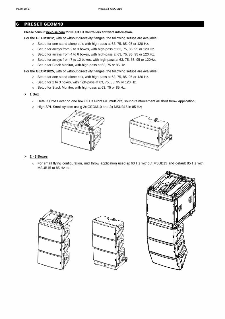
1 Box
o Default Cross over on one box 63 Hz Front Fill, multi-diff, sound reinforcement all short throw application;
o High SPL Small system using 2x GEOM10 and 2x MSUB15 in 85 Hz;
2 - 3 Boxes
o For small flying configuration, mid throw application used at 63 Hz without MSUB15 and default 85 Hz with
MSUB15 at 85 Hz too.

PRESET GEOM10 Page 11/17
o Possibilities to use 2-3Box setup in stack configuration using MSUB15 in OMNI or CARDIO mode with 1 Back
and 2 front and 3 GEOM10 on top of them, application venue up to 15 meters, default cross over 85 Hz but
small overlap could have impact if needed, for example (MSUB15 120 Hz and GEOM10 75 Hz).
4 - 6 Boxes
o For long throw flying application used in GEOM10 at 63 Hz without Sub and GEOM10 at 85 Hz with flying
MSUB15 in cardio mode at 95 Hz.
Page 12/17 PRESET GEOM10
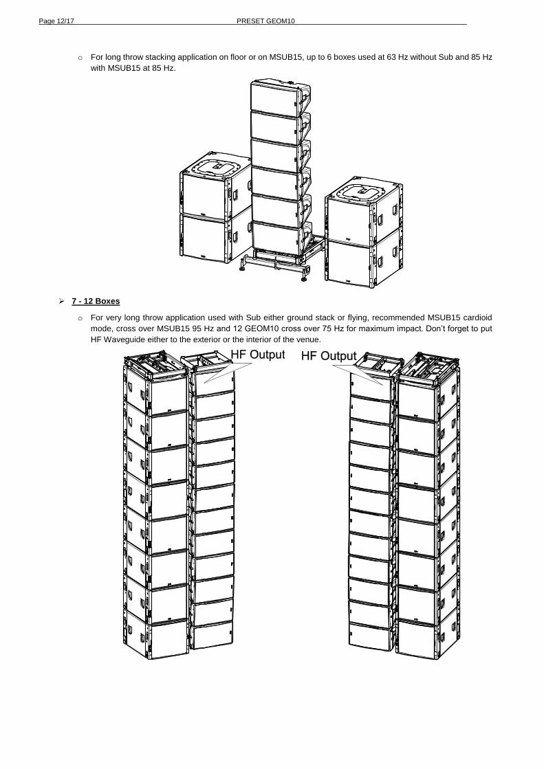
o For long throw stacking application on floor or on MSUB15, up to 6 boxes used at 63 Hz without Sub and 85 Hz
with MSUB15 at 85 Hz.
7 - 12 Boxes
o For very long throw application used with Sub either ground stack or flying, recommended MSUB15 cardioid
mode, cross over MSUB15 95 Hz and 12 GEOM10 cross over 75 Hz for maximum impact. Don’t forget to put
HF Waveguide either to the exterior or the interior of the venue.
PRESET GEOM10 Page 13/17
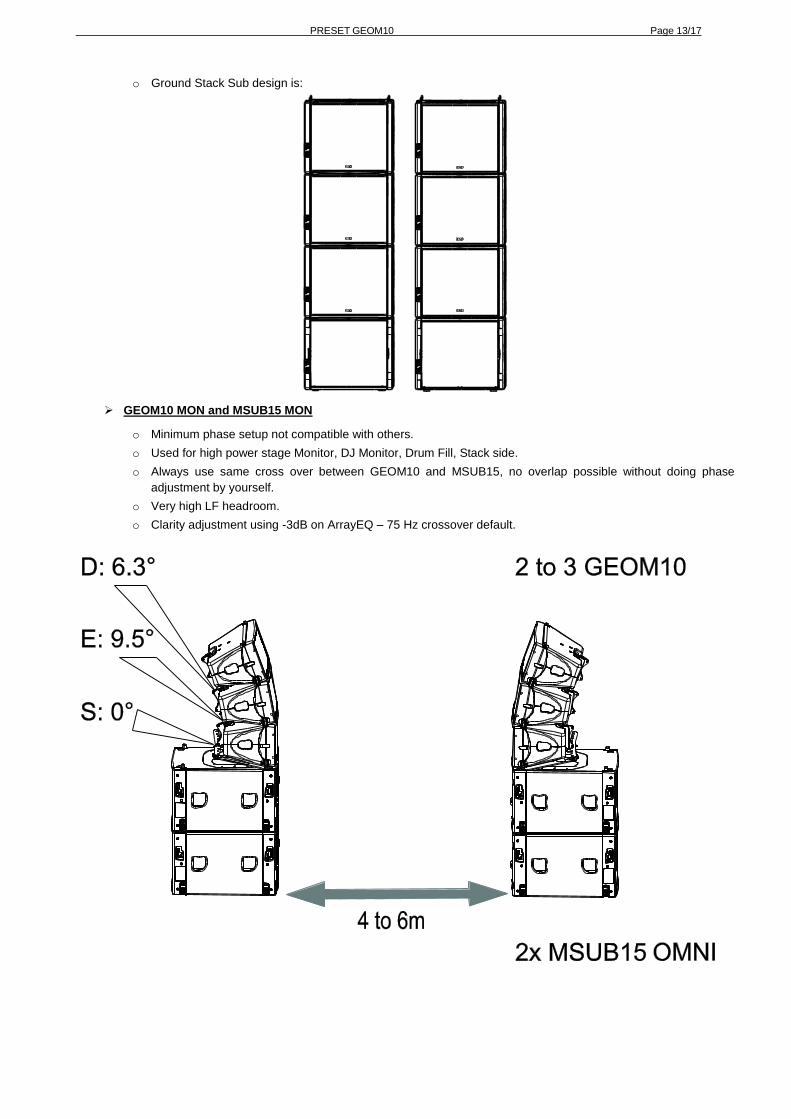
o Ground Stack Sub design is:
GEOM10 MON and MSUB15 MON
o Minimum phase setup not compatible with others.
o Used for high power stage Monitor, DJ Monitor, Drum Fill, Stack side.
o Always use same cross over between GEOM10 and MSUB15, no overlap possible without doing phase
adjustment by yourself.
o Very high LF headroom.
o Clarity adjustment using -3dB on ArrayEQ – 75 Hz crossover default.
Page 14/17 ARRAY EQ
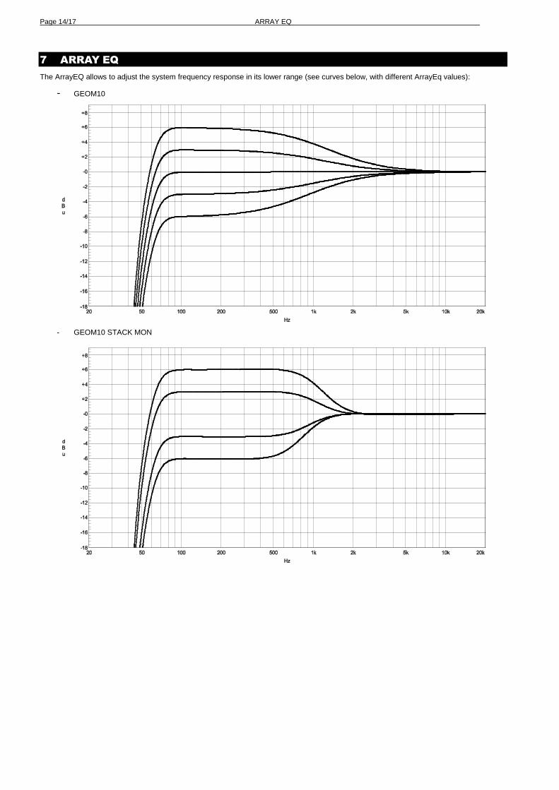
7 ARRAY EQ
The ArrayEQ allows to adjust the system frequency response in its lower range (see curves below, with different ArrayEq values):
- GEOM10
- GEOM10 STACK MON
MAINTENANCE Page 15/17
8 MAINTENANCE
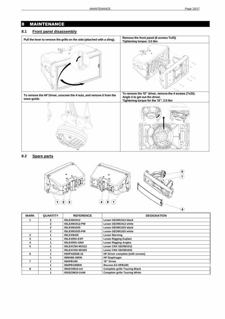
8.1 Front panel disassembly
Pull the lever to remove the grille on the side (attached with a sling). Remove the front panel (8 screws Tx25) Tightening torque: 3.5 Nm
To remove the HF Driver, unscrew the 4 nuts, and remove it from the wave guide.
To remove the 10’’ driver, remove the 4 screws (Tx25). Angle it to get out the driver. Tightening torque for the 10’’: 3.5 Nm
8.2 Spare parts
MARK QUANTITY REFERENCE DESIGNATION
1 2 05LEXM1012 Lexan GEOM1012 black
2 05LEXM1012-PW Lexan GEOM1012 white
2 05LEXM1025 Lexan GEOM1025 black
2 05LEXM1025-PW Lexan GEOM1025 white
2 1 05LEXWAR Lexan Warning
3 1 05LEXRIG-EXP Lexan Rigging Explain
4 1 05LEXRIG-ANG Lexan Rigging Angles
5 1 05LEXCNX-M1012 Lexan CNX GEOM1012
1 05LEXCNX-M1025 Lexan CNX GEOM1025
6 1 05HPADE68-16 HF Driver complete (with screws)
1 05NH68-16R/K HF Diaphragm
7 1 05HPB10N 10’’ Driver 1 05HPB10NR/K Recone Kit HPB10N
8 1 05GEOM10-UA Complete grille Touring Black
1 05GEOM10-UAW Complete grille Touring White
Page 16/17 TECHNICAL SPECIFICATIONS
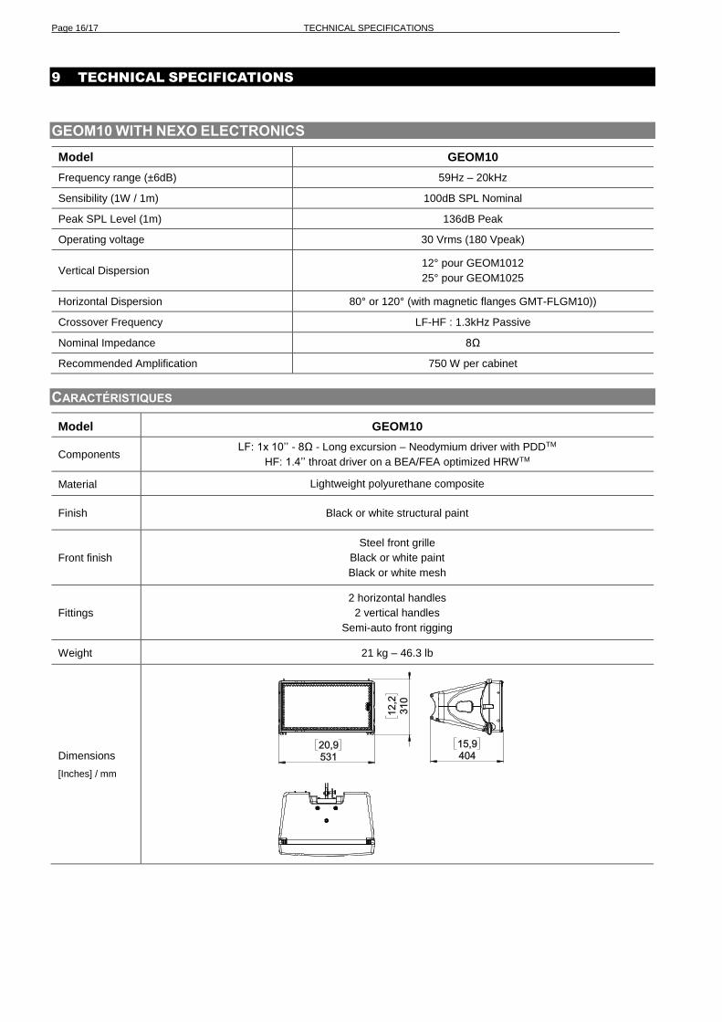
9 TECHNICAL SPECIFICATIONS
GEOM10 WITH NEXO ELECTRONICS
Model GEOM10
Frequency range (±6dB) 59Hz – 20kHz
Sensibility (1W / 1m) 100dB SPL Nominal
Peak SPL Level (1m) 136dB Peak
Operating voltage 30 Vrms (180 Vpeak)
Vertical Dispersion 12° pour GEOM1012
25° pour GEOM1025
Horizontal Dispersion 80° or 120° (with magnetic flanges GMT-FLGM10))
Crossover Frequency LF-HF : 1.3kHz Passive
Nominal Impedance 8Ω
Recommended Amplification 750 W per cabinet
CARACTÉRISTIQUES
Model GEOM10
Components LF: 1x 10’’ - 8Ω - Long excursion – Neodymium driver with PDDTM
HF: 1.4’’ throat driver on a BEA/FEA optimized HRWTM
Material Lightweight polyurethane composite
Finish Black or white structural paint
Front finish
Steel front grille
Black or white paint
Black or white mesh
Fittings
2 horizontal handles
2 vertical handles
Semi-auto front rigging
Weight 21 kg – 46.3 lb
Dimensions
[Inches] / mm
USER NOTES Page 17/17
10 USER NOTES
France
Nexo S.A. Parc d’activité de la Dame Jeanne
F-60128 PLAILLY
Tel: +33 3 44 99 00 70 Fax: +33 3 44 99 00 30
E-mail: [email protected]
nexo-sa.com