user manual mic-7500 - advantechadvdownload.advantech.com/productfile/downloadfile... · mic-7500...
TRANSCRIPT
User Manual
MIC-7500
Embedded IPC

Attention!Please note:
This package contains a hard-copy user manual in Chinese for China CCC certifica-tion purposes, and there is an English user manual included as a PDF file on the CD.Please disregard the Chinese hard copy user manual if the product is not to be soldand/or installed in China.
MIC-7500 User Manual ii

CopyrightThe documentation and the software included with this product are copyrighted 2016by Advantech Co., Ltd. All rights are reserved. Advantech Co., Ltd. reserves the rightto make improvements in the products described in this manual at any time withoutnotice.
No part of this manual may be reproduced, copied, translated or transmitted in anyform or by any means without the prior written permission of Advantech Co., Ltd.Information provided in this manual is intended to be accurate and reliable. However,Advantech Co., Ltd. assumes no responsibility for its use, nor for any infringementsof the rights of third parties, which may result from its use.
AcknowledgementsAward is a trademark of Award Software International, Inc.
Intel® and Pentium® are trademarks of Intel Corporation.
Microsoft Windows® is a registered trademark of Microsoft Corp.
Cooper is a trademark of Eaton Corporation.
Infineon is a trademark of Infineon Technologies.
TI is a trademark of Texas Instruments.
Asmedia is a trademark of Asmedia Technology INC.
Exar is a trademark of Exar Corporation.
INTERSIL is a trademark of Intersil Corporation.
Nuvoton is a trademark of Nuvoton Technology Corporation.
All other product names or trademarks are properties of their respective owners.
For more information about this and other Advantech products, please visit our web-site at:
http://www.advantech.com/
http://www.advantech.com/ePlatform/
For technical support and service, please visit our support website at:
http://support.advantech.com.tw/support/
Part No. 2001750010 Edition 1
Printed in China March 2016
iii MIC-7500 User Manual
Product Warranty (2 years)Advantech warrants to you, the original purchaser, that each of its products will befree from defects in materials and workmanship for two years from the date of pur-chase.
This warranty does not apply to any products which have been repaired or altered bypersons other than repair personnel authorized by Advantech, or which have beensubject to misuse, abuse, accident or improper installation. Advantech assumes noliability under the terms of this warranty as a consequence of such events.
Because of Advantech’s high quality-control standards and rigorous testing, most ofour customers never need to use our repair service. If an Advantech product is defec-tive, it will be repaired or replaced at no charge during the warranty period. For out-of-warranty repairs, you will be billed according to the cost of replacement materials,service time and freight. Please consult your dealer for more details.
If you think you have a defective product, follow these steps:
1. Collect all the information about the problem encountered. (For example, CPU speed, Advantech products used, other hardware and software used, etc.) Note anything abnormal and list any onscreen messages you get when the problem occurs.
2. Call your dealer and describe the problem. Please have your manual, product, and any helpful information readily available.
3. If your product is diagnosed as defective, obtain an RMA (return merchandise authorization) number from your dealer. This allows us to process your return more quickly.
4. Carefully pack the defective product, a fully-completed Repair and Replacement Order Card and a photocopy proof of purchase date (such as your sales receipt) in a shippable container. A product returned without proof of the purchase date is not eligible for warranty service.
5. Write the RMA number visibly on the outside of the package and ship it prepaid to your dealer.
Declaration of Conformity
FCC Class A
Note: This equipment has been tested and found to comply with the limits for a ClassA digital device, pursuant to part 15 of the FCC Rules. These limits are designed toprovide reasonable protection against harmful interference when the equipment isoperated in a commercial environment. This equipment generates, uses, and canradiate radio frequency energy and, if not installed and used in accordance with theinstruction manual, may cause harmful interference to radio communications. Opera-tion of this equipment in a residential area is likely to cause harmful interference inwhich case the user will be required to correct the interference at his own expense.
MIC-7500 User Manual iv

Technical Support and Assistance1. Visit the Advantech web site at www.advantech.com/support where you can find
the latest information about the product.2. Contact your distributor, sales representative, or Advantech's customer service
center for technical support if you need additional assistance. Please have the following information ready before you call:– Product name and serial number– Description of your peripheral attachments– Description of your software (operating system, version, application software,
etc.)– A complete description of the problem– The exact wording of any error messages
Warnings, Cautions and Notes
Warning! Warnings indicate conditions in which there is a chance of personal injury!
Caution! Cautions are included to help you avoid damaging hardware or losing data. e.g.:
There is a danger of a new battery exploding if it is incorrectly installed. Do not attempt to recharge, force open, or heat the battery. Replace the battery only with the same or equivalent type recommended by the man-ufacturer. Discard used batteries according to the manufacturer's instructions.
Note! Notes provide optional additional information.
v MIC-7500 User Manual
Safety Instructions1. Please read these safety instructions carefully.2. Please keep this User’s Manual for later reference.3. Please disconnect this equipment from AC outlet before cleaning. Use a damp
cloth. Don’t use liquid or sprayed detergent for cleaning. Use moist sheet or cloth for cleaning.
4. For pluggable equipment, the socket-outlet shall near the equipment and shall be easily accessible.
5. Please keep this equipment from humidity.6. Lay this equipment on a reliable surface when installing. A drop or fall could
cause injury.7. The openings on the enclosure are for air convection hence protecting the
equipment from overheating. DO NOT COVER THE OPENINGS.8. Make sure the voltage of the power source when connecting the equipment to
the power outlet.9. Place the power cord such a way that people cannot step on it. Do not place
anything over the power cord. 10. All cautions and warnings on the equipment should be noted.11. If the equipment is not used for long time, disconnect the equipment from mains
to avoid being damaged by transient over-voltage.12. Never pour any liquid into ventilation openings; this could cause fire or electrical
shock.13. Never open the equipment. For safety reasons, only qualified service personnel
should open the equipment.14. If one of the following situations arises, get the equipment checked by service
personnel:The power cord or plug is damaged.Liquid has penetrated into the equipment.The equipment has been exposed to moisture.The equipment does not work well, or you cannot get it to work according to
the user's manual.The equipment has been dropped and damaged.The equipment has obvious signs of breakage.
15. DO NOT LEAVE THIS EQUIPMENT IN AN ENVIRONMENT WHERE THE STORAGE TEMPERATURE MAY GO BELOW -40° C (-40° F) OR ABOVE 85° C (185° F). THIS COULD DAMAGE THE EQUIPMENT. THE EQUIPMENT SHOULD BE IN A CONTROLLED ENVIRONMENT.
16. CAUTION: DANGER OF EXPLOSION IF BATTERY IS INCORRECTLY REPLACED. REPLACE ONLY WITH THE SAME OR EQUIVALENT TYPE RECOMMENDED BY THE MANUFACTURER, DISCARD USED BATTERIES ACCORDING TO THE MANUFACTURER'S INSTRUCTIONS.
17. The sound pressure level at the operator's position according to IEC 704-1:1982 is no more than 70 dB (A).
18. RESTRICTED ACCESS AREA: The equipment should only be installed in a Restricted Access Area.
DISCLAIMER: This set of instructions is given according to IEC 704-1. Advantechdisclaims all responsibility for the accuracy of any statements contained herein.
MIC-7500 User Manual vi
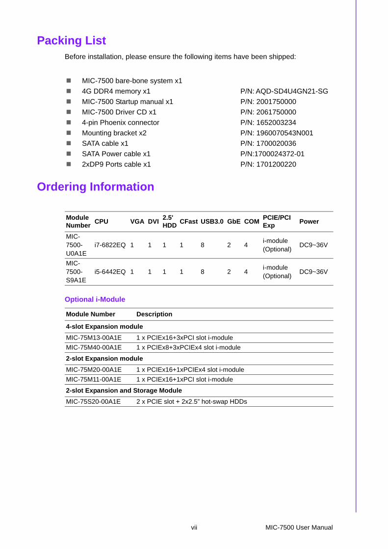
Packing ListBefore installation, please ensure the following items have been shipped:
Ordering Information
Optional i-Module
MIC-7500 bare-bone system x1
4G DDR4 memory x1 P/N: AQD-SD4U4GN21-SG
MIC-7500 Startup manual x1 P/N: 2001750000
MIC-7500 Driver CD x1 P/N: 2061750000
4-pin Phoenix connector P/N: 1652003234
Mounting bracket x2 P/N: 1960070543N001
SATA cable x1 P/N: 1700020036
SATA Power cable x1 P/N:1700024372-01
2xDP9 Ports cable x1 P/N: 1701200220
Module Number
CPU VGA DVI2.5'HDD
CFast USB3.0 GbE COMPCIE/PCI Exp
Power
MIC-7500-U0A1E
i7-6822EQ 1 1 1 1 8 2 4i-module (Optional)
DC9~36V
MIC-7500-S9A1E
i5-6442EQ 1 1 1 1 8 2 4i-module (Optional)
DC9~36V
Module Number Description
4-slot Expansion module
MIC-75M13-00A1E 1 x PCIEx16+3xPCI slot i-module
MIC-75M40-00A1E 1 x PCIEx8+3xPCIEx4 slot i-module
2-slot Expansion module
MIC-75M20-00A1E 1 x PCIEx16+1xPCIEx4 slot i-module
MIC-75M11-00A1E 1 x PCIEx16+1xPCI slot i-module
2-slot Expansion and Storage Module
MIC-75S20-00A1E 2 x PCIE slot + 2x2.5” hot-swap HDDs
vii MIC-7500 User Manual

Optional Accessories
i-module Optional Accessories
Part Number Description
96PSA-A220W24P4-1 ADP A/D 100-240V 220W 24V
96PSA-A150W19P4-1 ADP A/D 100-240V 150W 19V
96PSA-A120W24T2 ADP A/D 100-240V 120W 24V
96PSA-A120W19T2 ADP A/P 100-240V 120W 19V
1702002600 Power Cord 3P UL/CSA(USA) 125V 10A 1.83M 180D
1700022940-01 Power cord PSE 7A 125V 3P 3m DAC-ST01
1702002605 Power cord 2P FRANCE 10A/16A 220V 1.83M 90D
AIIS-DIO32-00A1E AIIS-32bit GPIO module
98R2C48510E Isolation COM module
i-Door Module(MOS series module)
Supports i-Door module (MOS series), except PoEPlease refer to Advantech website below or search "iDoor Module Mini PCIe Expansion Kit".http://www.advantech.com.tw/products/idoor-module-mini-pcie-expansion-kit/sub_bc858a7f-a52b-441b-a59c-f511289f98bc
i-Door Module(PCM series module)
Supports i-Door module (PCM series) except PoEPlease refer to Advantech website below:http://www.advantech.com/products/idoor-technology-mini-pcieex-pansion-kit/sub_efdb96af-a8f7-4cde-9592-dbf5c9794d16Note: A bracket is required to fix PCM series i-door module. Pleaser refer to P/N:1960065854N001 i Door_bracket
Part Number Description
98R1751300E 1x8cm FAN module (for MIC-75M13/75M40/75S20)
98R1752000E 2x4cm FAN module (for MIC-75M20/MIC-75M11)
MIC-7500 User Manual viii

Contents
Chapter 1 General Introduction ...........................11.1 Introduction ............................................................................................... 21.2 Product Features....................................................................................... 2
1.2.1 General ......................................................................................... 21.2.2 Display .......................................................................................... 21.2.3 Ethernet ........................................................................................ 2
1.3 Chipset ...................................................................................................... 31.3.1 Functional specification................................................................. 3
1.4 Mechanical Specifications......................................................................... 41.4.1 Dimensions ................................................................................... 4
Figure 1.1 MIC-7500 Mechanical Dimension Drawing ................ 41.4.2 Weight........................................................................................... 5
1.5 Power Requirements................................................................................. 51.5.1 System power ............................................................................... 51.5.2 RTC battery................................................................................... 5
1.6 Environment Specification......................................................................... 51.6.1 Operating temperature.................................................................. 51.6.2 System safety certification test temperature ................................. 51.6.3 Relative humidity........................................................................... 51.6.4 Storage temperature ..................................................................... 51.6.5 Vibration during operation............................................................. 51.6.6 Shock during operation ................................................................. 51.6.7 Safety............................................................................................ 51.6.8 EMC.............................................................................................. 5
Chapter 2 H/W Installation....................................72.1 Introduction ............................................................................................... 82.2 Jumpers .................................................................................................... 8
2.2.1 Jumper description........................................................................ 82.2.2 Jumper list..................................................................................... 9
Table 2.1: Jumper List ................................................................. 92.3 Connectors.............................................................................................. 10
2.3.1 MIC-7500 External I/O Connectors............................................. 10Figure 2.1 MIC-7500 Front View................................................ 10Table 2.2: COM Connector Pin Assignments............................ 10Figure 2.2 Ethernet Connector .................................................. 11Table 2.3: Ethernet Connector Pin Assignments....................... 11Figure 2.3 Audio Connector....................................................... 11Table 2.4: Audio Connector Pin Assignments ........................... 11Figure 2.4 USB 3.0 Connector................................................... 12Table 2.5: USB 3.0 Connector Pin Assignment......................... 12Figure 2.5 VGA Connector ........................................................ 12Table 2.6: VGA Connector Pin Assignments............................. 12Figure 2.6 Parallel Port Connector ............................................ 13Table 2.7: DVI-D Port Connector Pin Assignments................... 13Figure 2.7 4-pin header ............................................................. 13Table 2.8: Pin Assignments for Power Connector Pin Header.. 13Figure 2.8 Power Button ............................................................ 14Figure 2.9 LED Indicators .......................................................... 14
2.4 Installation ............................................................................................... 142.4.1 HDD installation .......................................................................... 142.4.2 Memory Installation..................................................................... 162.4.3 m-SATA/Mini-PCIe Installation ................................................... 17
ix MIC-7500 User Manual

2.4.4 Internal USB 2.0 Installation ....................................................... 172.4.5 COM 5/6 Ports Installation.......................................................... 182.4.6 Expansion module Installation (Optional) ................................... 192.4.7 MIC-7500 MB IO connector ........................................................ 20
Chapter 3 AMI BIOS Setup................................. 213.1 Introduction ............................................................................................. 223.2 Entering Setup ........................................................................................ 23
3.2.1 Main Setup.................................................................................. 233.2.2 Advanced BIOS Features Setup................................................. 243.2.3 Chipset........................................................................................ 453.2.4 Security....................................................................................... 583.2.5 Boot ............................................................................................ 593.2.6 Save & Exit ................................................................................. 60
Chapter 4 Software Installation......................... 614.1 Chipset Software Installation Utility......................................................... 62
4.1.1 Before you begin......................................................................... 624.1.2 Introduction ................................................................................. 624.1.3 Windows 10 / Windows 8.1/ Windows 7 ..................................... 63
4.2 Integrated Graphic Device Setup............................................................ 634.2.1 Introduction ................................................................................. 634.2.2 Windows 10 /Windows 8.1 /Windows 7 Driver Setup ................. 64
4.3 Intel® ME ................................................................................................ 644.3.1 Introduction ................................................................................. 644.3.2 Installation................................................................................... 644.3.3 Install Intel® ME for Windows 7.................................................. 65
4.4 LAN Configuration................................................................................... 654.4.1 Introduction ................................................................................. 654.4.2 Features...................................................................................... 654.4.3 Installation................................................................................... 664.4.4 Windows 10 /Windows 8.1 /Windows 7 ...................................... 66
4.5 SATA RAID Setup................................................................................... 674.5.1 Introduction ................................................................................. 674.5.2 SATA RAID Driver and Utility Setup ........................................... 67
4.6 Install USB3.0 ......................................................................................... 674.6.1 Introduction ................................................................................. 67
Appendix A Programming the Watchdog Timer . 69A.1 Programming the Watchdog Timer ......................................................... 70
A.1.1 Watchdog Timer Overview ......................................................... 70A.1.2 Programming the Watchdog Timer............................................. 70
Table A.1: Watchdog Timer Registers....................................... 72A.1.3 Example Program....................................................................... 73
Appendix B Programming the GPIO .................... 77B.1 Supported GPIO Register ....................................................................... 78
B.1.1 GPIO Registers........................................................................... 78B.1.2 GPIO Example Program............................................................. 79
MIC-7500 User Manual x

Chapter 1
1 General IntroductionThis chapter gives background information on MIC-7500.
1.1 IntroductionMIC-7500 is a compact, fanless system incorporating late-generation Intel® 14nmplatform with the new PCH_QM170 processer on a proprietary form factor M/B. MIC-7500 system design concept is that of “the expansion slot module”, so different appli-cations can integrate the MIC-7500 system to form a complete industrial computer.
The MIC-7500 also can serve as an independent, fanless, Compact Embedded Boxand accepts a wide range of DC power inputs. The rugged aluminum case not onlyprovides a great thermal solution, but also resists high EMI/shock/vibration. MIC-7500is equipped with Intel® 6th Generation Core™ i CPU featuring 8 cores, making ithighly suitable for embedded and industrial PC applications requiring high processorperformance within a limited space. It features powerful I/O interfaces, includingEthernet, USB 3.0, serial port, C-Fast slot, and two Mini PCIes.
1.2 Product Features
1.2.1 General
CPU: Intel® 6th gen Core™ i Processor PCH: Intel® QM170 System Memory: Dual 260pin SODIMM DDR4 socket, up to 32GB HDD:
– Supports 1 drive bay space for SATA 2.5" HDD/SSD – Supports 1 CFast slot
mSATA: Supports 1 x mSATA by Mini PCIe slot Graphic: VGA + DVI Ethernet Port: 2 x RJ45 Watchdog Timer: Single chip Watchdog 255-level interval timer, setup by soft-
ware I/O Interface: 2 x RS232/422/485 / 2x RS-232 USB: 8 x USB3.0 Audio: High Definition Audio (HD), Line-out, Mic-in Expansion interface: 2 x Mini PCIe sockets (1 x U-SIM, 1 x m-SATA)
1.2.2 Display Chipset: Intel® HD Graphics 530, support DirectX 12 Graphics Video Max Memory: 1.7 GB Resolution:
– VGA: Supports up to 2048 x 1152 @ 60 Hz– DVI: Supports up to 1920 x 1080 @ 60 Hz
1.2.3 Ethernet Chipset:
– LAN 1: Intel® i219LM– LAN 2: Intel® i210IT
Speed: 10/100/1000 Mbps Interface: 2 x RJ45 Standarsd: Compliant with IEEE 802.3, IEEE802.3U, IEEE 802.ab.
MIC-7500 User Manual 2
Chapter 1
GeneralIntroduction
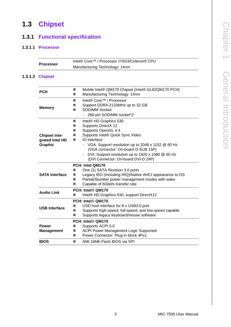
1.3 Chipset
1.3.1 Functional specification
1.3.1.1 Processor
1.3.1.2 Chipset
ProcessorIntel® Core™ i Processor i7/i5/i3/Celeron® CPU
Manufacturing Technology: 14nm
PCH Mobile Intel® QM170 Chipset (Intel® GL82QM170 PCH) Manufacturing Technology: 14nm
Memory
Intel® Core™ i Processor Support DDR4-2133MHz up to 32 GB SODIMM Socket:
– 260-pin SODIMM socket*2
Chipset inte-grated Intel HD Graphic
Intel® HD Graphics 530 Supports DirectX 12 Supports OpenGL 4.4 Supports Intel® Quick Sync Video IO interface
– VGA: Support resolution up to 2048 x 1152 @ 60 Hz (VGA connector: On-board D-SUB 15P)
– DVI: Support resolution up to 1920 x 1080 @ 60 Hz(DVI Connector: On-board DVI-D 24P)
SATA Interface
PCH: Intel QM170 One (1) SATA Revision 3.0 ports Legacy IED (Including IRQ)/Native AHCI appearance to OS Partial/Slumber power management modes with wake Capable of 6Gbit/s transfer rate
Audio LinkPCH: Intel® QM170 Intel® HD Graphics 530, support DirectX12
USB Interface
PCH: Intel® QM170 USD host interface for 8 x USB3.0 port Supports high-speed, full-speed, and low-speed capable Supports legacy keyboard/mouse software
PowerManagement
PCH: Intel® QM170 Supports ACPI 5.0 ACPI Power Management Logic Supported Power Connector: Plug-in block 4Px1
BIOS AMI 16Mb Flash BIOS via SPI
3 MIC-7500 User Manual

1.3.1.3 Others
1.4 Mechanical Specifications
1.4.1 Dimensions
Figure 1.1 MIC-7500 Mechanical Dimension Drawing
Serial ports
Nuvoton NCT 6106D supported Up to 6 serial ports by Nuvoton NCT6106D supported High speed NS16C550A compatible UARTs with date rates to 1.5
Mbps Supports IRQ sharing among serial port on XPE COM1/2: Support to RS-232/422/485 and setting mode by BIOS and
supports auto flow control COM 3~6: Support to RS-232
Serial ports connector: D-SUB CON.9P
LAN
LAN1: Intel® i219LM; LAN2: Intel® i210IT Compliant with IEEE 802.3, IEEE 802.3u, IEEE 802.ab. Supports 10/100/1000 Mbps Supports Wake on LAN
Audio
Audio Codec: Realtek ALC892: Compliant with HD Audio specifications Supports to 16/20/24-bit DAC and 16/20/24-bit ADC resolution Support: Line-out, Mic-in DAC supports 16/20/24-bit PCM format, multiple stereo recording
Battery backup BR2032 3 V/190mAh
73 78.2
0
192
230
2218
615
018
226252
14 5
10
14
UNIT : mm
MIC-7500 User Manual 4

Chapter 1
GeneralIntroduction
1.4.2 Weight2.9kg (6.39lbs)
1.5 Power Requirements
1.5.1 System power Minimum power input: DC12V (-25%) -30V (+20%), Absolute Maximum Ratings
Voltage is 9V - 36V
1.5.2 RTC battery BR2032 3 V/190 mAh
1.6 Environment Specification
1.6.1 Operating temperature -20 ~ 60 °C with 0.7m/sec air flow: with 1 x Industrial SSD without PC expansion
boards
1.6.2 System safety certification test temperature 0 ~ 50 °C with 2.5” HDD
1.6.3 Relative humidity 95% @ 40 °C (non-condensing)
1.6.4 Storage temperature -40 ~ 85 °C (-40 ~ 185 °F)
1.6.5 Vibration during operation When system is equipped with SSD only: 3 Grms, IEC 60068-2-64, random, 5 ~
500 Hz, 1 Oct/min., 1 hr/axis, x,y,z 3 axes. When system is equipped with 2.5-inch HDD: 1 Grms, IEC 60068-2-64, random,
5 ~ 500 Hz, 1 Oct/min., 1 hr/axis, x,y,z 3 axes.
1.6.6 Shock during operation When system is equipped with SSD only: 20 G, IEC 60068-2-27, half sine, 11
ms duration.
1.6.7 Safety CCC, BSMI
1.6.8 EMC CE, FCC, CCC, BSMI
5 MIC-7500 User Manual

MIC-7500 User Manual 6

Chapter 2
2 H/W InstallationThis chapter introduces external IO and the installation of MIC-7500 hardware.
2.1 IntroductionThe following sections show the internal jumper settings and the external connectorsand pins assignment for applications.
2.2 Jumpers
2.2.1 Jumper descriptionYou may configure the MIC-7500 to match the needs of your application by settingjumpers. A jumper is a metal bridge used to close an electric circuit. It consists of twometal pins and a small metal clip (often protected by a plastic cover) that slides overthe pins to connect them. To close a jumper, you connect the pins with the clip. Toopen a jumper, you remove the clip. Sometimes a jumper will have three pins,labeled 1, 2 and 3. In this case you would connect either pins 1 and 2, or 2 and 3.
The jumper settings are schematically depicted in this manual as follows.
A pair of needle-nose pliers may be helpful when working with jumpers. If you haveany doubts about the best hardware configuration for your application, contact yourlocal distributor or sales representative before you make any changes. Generally, yousimply need a standard cable to make most connections.
closed 2-3closedopen
1 2 1 2
closed 2-3closedopen
MIC-7500 User Manual 8
Chapter 2
H/W
Installation
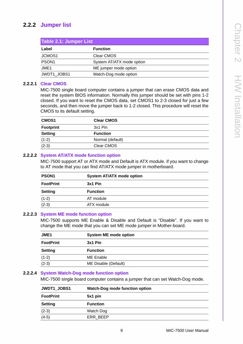
2.2.2 Jumper list
2.2.2.1 Clear CMOSMIC-7500 single board computer contains a jumper that can erase CMOS data andreset the system BIOS information. Normally this jumper should be set with pins 1-2closed. If you want to reset the CMOS data, set CMOS1 to 2-3 closed for just a fewseconds, and then move the jumper back to 1-2 closed. This procedure will reset theCMOS to its default setting.
2.2.2.2 System AT/ATX mode function optionMIC-7500 support AT or ATX mode and Default is ATX module. if you want to changeto AT mode that you can find AT/ATX mode jumper in motherboard.
2.2.2.3 System ME mode function optionMIC-7500 supports ME Enable & Disable and Default is “Disable”. If you want tochange the ME mode that you can set ME mode jumper in Mother-board.
2.2.2.4 System Watch-Dog mode function optionMIC-7500 single board computer contains a jumper that can set Watch-Dog mode.
Table 2.1: Jumper List
Label Function
JCMOS1 Clear CMOS
PSON1 System AT/ATX mode option
JME1 ME jumper mode option
JWDT1_JOBS1 Watch-Dog mode option
CMOS1 Clear CMOS
Footprint 3x1 Pin
Setting Function
(1-2) Normal (default)
(2-3) Clear CMOS
PSON1 System AT/ATX mode option
FootPrint 3x1 Pin
Setting Function
(1-2) AT module
(2-3) ATX module
JME1 System ME mode option
FootPrint 3x1 Pin
Setting Function
(1-2) ME Enable
(2-3) ME Disable (Default)
JWDT1_JOBS1 Watch-Dog mode function option
FootPrint 5x1 pin
Setting Function
(2-3) Watch Dog
(4-5) ERR_BEEP
9 MIC-7500 User Manual

2.3 Connectors
2.3.1 MIC-7500 External I/O Connectors
Figure 2.1 MIC-7500 Front View
2.3.1.1 COM connectorMIC-7500 provides four 9-pin D-sub connectors, two of which offer RS-232/422/485and the other two offer RS-232 serial communication interface ports. Default setting isRS-232, but this can be modified by BIOS setting. You can find detailed setting meth-ods in Chapter 3.
USB 3.0LAN1/2 COM 1/2
CFast SocketPower 9 -36VDC
Line-outMic-in
COM 3/4
DVI VGA
COM1TX/RX
COM2TX/RX
Table 2.2: COM Connector Pin Assignments
RS-232 RS-422 RS-485
Pin Signal Name Signal Name Signal Name
1 DCD Tx- DATA-
2 RxD Tx+ DATA+
3 TxD Rx+ NC
4 DTR Rx- NC
5 GND GND GND
6 DSR NC NC
7 RTS NC NC
8 CTS NC NC
9 RI NC NC
Note! NC represents “No Connection”.
MIC-7500 User Manual 10

Chapter 2
H/W
Installation
2.3.1.2 Ethernet connector (LAN)MIC-7500 is equipped with two Ethernet controllers that are fully compliant with IEEE802.3u 10/100/1000 Mbps CSMA/CD standards. LAN1 is equipped with Intel i219LMand LAN2 is equipped with Intel i210IT. The Ethernet port provides a standard RJ45jack connector with LED indicators on the front side to show its Active/Link status andSpeed status.
Figure 2.2 Ethernet Connector
2.3.1.3 Audio connectorMIC-7500 has two stereo audio ports with phone jack connectors, one Line_Out, oneMic_In. The audio chip is controlled by ACL892, and it’s compliant with AZALIA stan-dard.
Figure 2.3 Audio Connector
Table 2.3: Ethernet Connector Pin Assignments
Pin 10/100/1000BaseT Signal Name
1 TX+
2 TX-
3 RX+
4 MDI2+
5 MDI2-
6 RX-
7 MDI3+
8 MDI3-
18
Table 2.4: Audio Connector Pin Assignments
Pin Audio Signal Name
1 Line_Out
2 Mic_In
11 MIC-7500 User Manual

2.3.1.4 USB 3.0 connectorMIC-7500 provides 8 USB 3.0 interface connectors, which give complete Plug & Playand hot swapping for up to 127 external devices. The USB interface complies withUSB XHCI, Rev. 3.0. Please refer to the table below for pin assignments.
Figure 2.4 USB 3.0 Connector
2.3.1.5 VGA ConnectorThe MIC-7500 provides a high resolution VGA interface with a 15-pin D-sub connec-tor to support a VGA CRT monitor. It supports display resolution of up to 2048 x 1152@ 60 Hz.
Figure 2.5 VGA Connector
Table 2.5: USB 3.0 Connector Pin AssignmentPin 1 +5V
Pin 2 USB Data -
Pin 3 USB Data +
Pin 4 GND
Pin 5 SSRX-
Pin 6 SSRX+
Pin 7 GND
Pin 8 SSTX-
Pin 9 SSTX+
Table 2.6: VGA Connector Pin Assignments
Pin Signal Name Pin Signal Name
1 Red 2 Green
3 Blue 4 NC
5 GND 6 GND
7 GND 8 GND
9 +5V 10 GND
11 NC 12 DDC_DAT
13 H-SYNC 14 V-SYNC
15 DDC_CLK
156
111015
MIC-7500 User Manual 12
Chapter 2
H/W
Installation
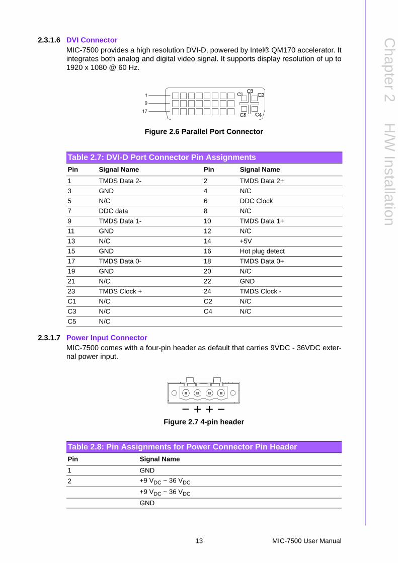
2.3.1.6 DVI ConnectorMIC-7500 provides a high resolution DVI-D, powered by Intel® QM170 accelerator. Itintegrates both analog and digital video signal. It supports display resolution of up to1920 x 1080 @ 60 Hz.
Figure 2.6 Parallel Port Connector
2.3.1.7 Power Input ConnectorMIC-7500 comes with a four-pin header as default that carries 9VDC - 36VDC exter-nal power input.
Figure 2.7 4-pin header
Table 2.7: DVI-D Port Connector Pin Assignments
Pin Signal Name Pin Signal Name
1 TMDS Data 2- 2 TMDS Data 2+
3 GND 4 N/C
5 N/C 6 DDC Clock
7 DDC data 8 N/C
9 TMDS Data 1- 10 TMDS Data 1+
11 GND 12 N/C
13 N/C 14 +5V
15 GND 16 Hot plug detect
17 TMDS Data 0- 18 TMDS Data 0+
19 GND 20 N/C
21 N/C 22 GND
23 TMDS Clock + 24 TMDS Clock -
C1 N/C C2 N/C
C3 N/C C4 N/C
C5 N/C
19
17
Table 2.8: Pin Assignments for Power Connector Pin Header
Pin Signal Name
1 GND
2 +9 VDC ~ 36 VDC
+9 VDC ~ 36 VDC
GND
13 MIC-7500 User Manual

2.3.1.8 Power ON/OFF buttonMIC-7500 comes with a Power On/Off button with LED indicators on the front side toshow its On status (Green LED) and Off/Suspend status (RED LED), that supportsdual function of Soft Power-On/Off (instant off or delay 4 seconds), and suspend.
Figure 2.8 Power Button
2.3.1.9 LED IndicatorsMIC-7500 provides COM1 & COM2 TX/RX LED for date transmission status monitor-ing.
Figure 2.9 LED Indicators
2.4 Installation
2.4.1 HDD installation1. Undo 4 screws and remove the bottom cover2. Undo 4 screws to remove HDD tray.
COM2 : TX/RXTXRX
TXRXCOM1 : TX/RX
HDD status
1
1
1
1
2
2
2
MIC-7500 User Manual 14

Chapter 2
H/W
Installation
3. Secure the HDD with 4xHDD screws (P/N:1930002235)4. Assemble SATA cable/power cable and replace HDD tray; secure with 4 screws.5. Replace bottom cover.
Note! Please refer to i-module Manual for i-module assembly.
2
2
2
2
3
3
3
3
15 MIC-7500 User Manual

2.4.2 Memory InstallationThe MIC-7500 system has 4GB memory on board; if you want to add more memory,please connect your distributor or sales representative to order compatible memorymodules. Part numbers below:
4G SO-DDR4-2133 512X8 1.2V SAM P/N: AQD-SD4U4GN21-SG 8G SO-DDR4-2133 512X8 1.2V SAM P/N: AQD-SD4U8GN21-SG 16GB DDR4 2133 1.2V SODIMM 1GbX8 SAM P/N: AQD-SD4U16N21-SE
1. Undo the 4 screws to remove the bottom cover.2. Undo 4 screws to remove the HDD tray.
3. Undo 3 screws to remove the memory thermal cover.4. Affix thermal pad (P/N: 1990019498N000) on memory, and reassemble
memory.
Note! If non-compliant SODIMM memory boards are installed in the MIC-7500, the system will not boot.
Note! Thermal pad and memory thermal cover must be completely covered and secured.
Note! Default configuration of the MIC-7500 has 4GB memory and one ther-mal pad inside. There is also 1 pc thermal pad in the accessory box.
4
3
3
MIC-7500 User Manual 16
Chapter 2
H/W
Installation
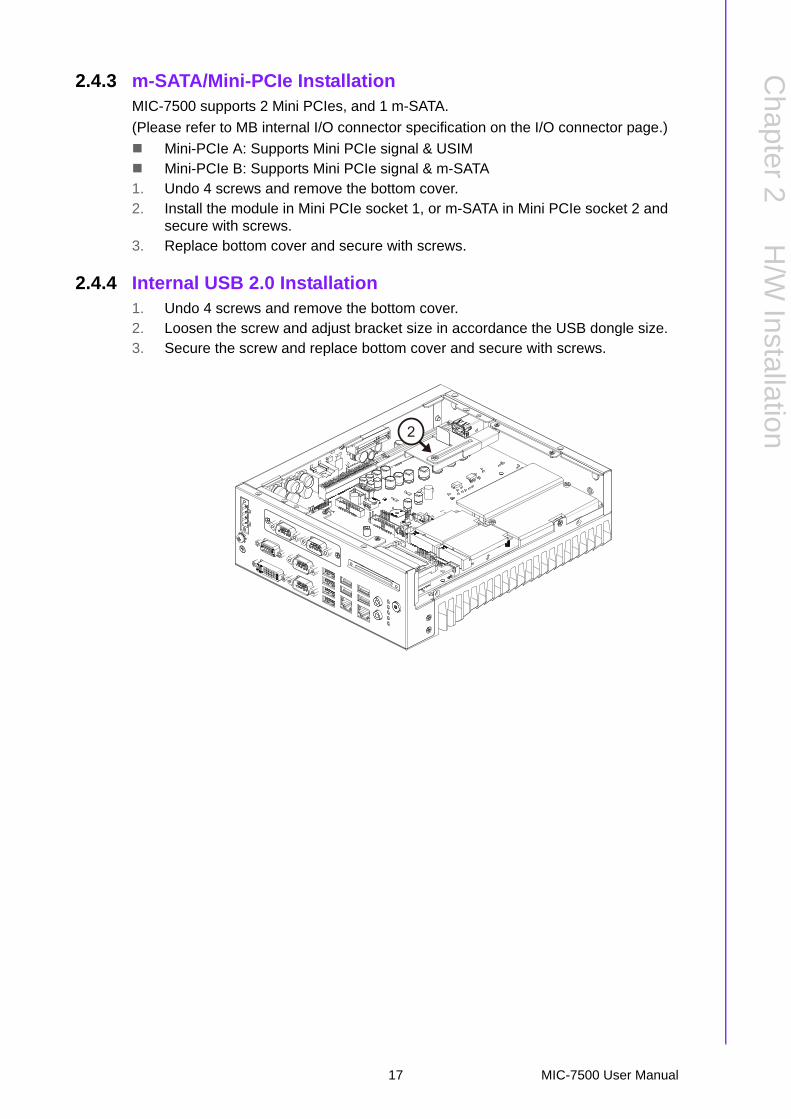
2.4.3 m-SATA/Mini-PCIe InstallationMIC-7500 supports 2 Mini PCIes, and 1 m-SATA.
(Please refer to MB internal I/O connector specification on the I/O connector page.)
Mini-PCIe A: Supports Mini PCIe signal & USIM Mini-PCIe B: Supports Mini PCIe signal & m-SATA1. Undo 4 screws and remove the bottom cover.2. Install the module in Mini PCIe socket 1, or m-SATA in Mini PCIe socket 2 and
secure with screws.3. Replace bottom cover and secure with screws.
2.4.4 Internal USB 2.0 Installation1. Undo 4 screws and remove the bottom cover.2. Loosen the screw and adjust bracket size in accordance the USB dongle size.3. Secure the screw and replace bottom cover and secure with screws.
2
17 MIC-7500 User Manual
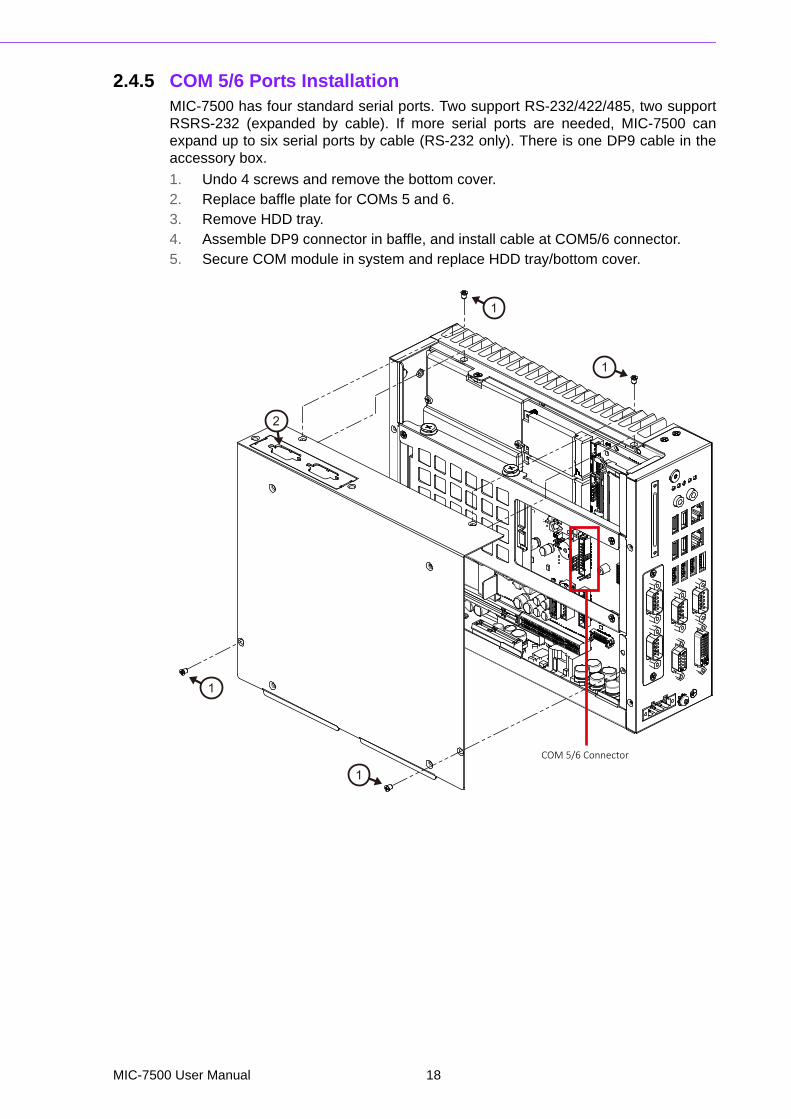
2.4.5 COM 5/6 Ports Installation MIC-7500 has four standard serial ports. Two support RS-232/422/485, two supportRSRS-232 (expanded by cable). If more serial ports are needed, MIC-7500 canexpand up to six serial ports by cable (RS-232 only). There is one DP9 cable in theaccessory box.
1. Undo 4 screws and remove the bottom cover.2. Replace baffle plate for COMs 5 and 6.3. Remove HDD tray.4. Assemble DP9 connector in baffle, and install cable at COM5/6 connector.5. Secure COM module in system and replace HDD tray/bottom cover.
1
1
1
1
2
COM 5/6 Connector
MIC-7500 User Manual 18

Chapter 2
H/W
Installation
2.4.6 Expansion module Installation (Optional)MIC-7500 supports two kinds of optional modules for different applications.
32bit GPIO module, P/N: AIIS-DIO32-00A1E 4 x Isolation COM module, P/N: 98R2C48510E1. Undo the 4 screws and remove the bottom cover.2. Undo HDD tray & expansion module baffle.
3. Remove COM cable and undo baffle cover.4. Assemble module on M/B (Note: 32Bit GPIO module needs to connect with a
cable. (Please refer to MB internal I/O connector specification at IO connector page for GPIO connector.)
5. Assemble module baffle with screws.6. Replace bottom cover and secure with screws.
44
4
5
19 MIC-7500 User Manual
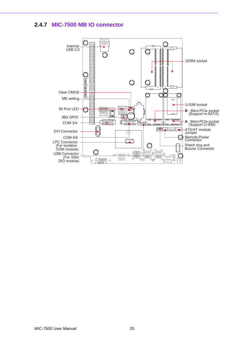
2.4.7 MIC-7500 MB IO connector
Remote Power
ATX/AT module
A : Mimi-PCIe socket
B : Mimi-PCIe socket
(Support U-SIM)
(Support m-SATA)
U-SIM socket
DDR4 socket
Internal
Clear CMOS
80 Port LED
8Bit GPIOCOM 3/4
COM 5/6
DVI Connector
LPC Connector
USB Connector(For 32bit
(For Isolation Watch dog and
ME setting
Buzzer Connector
Jumper
Connector
DIO module)
COM module)
USB 2.0
MIC-7500 User Manual 20
Chapter 3
3 AMI BIOS SetupThis chapter introduces how to set BIOS configuration data.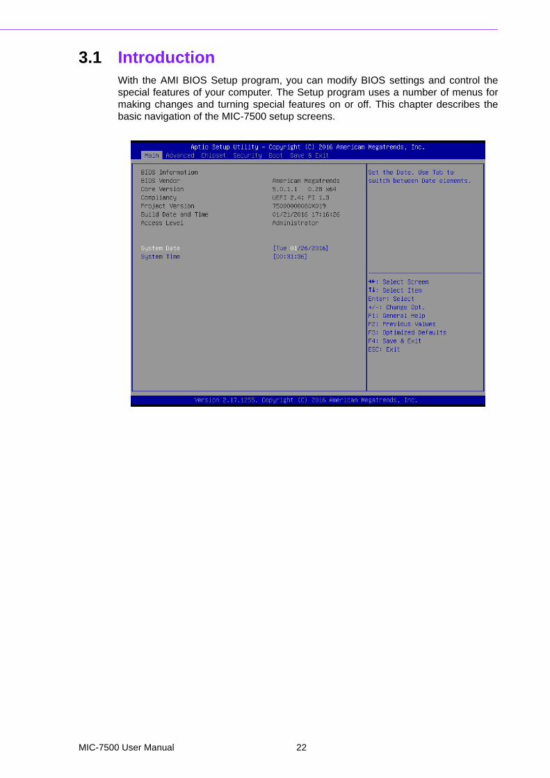
3.1 IntroductionWith the AMI BIOS Setup program, you can modify BIOS settings and control thespecial features of your computer. The Setup program uses a number of menus formaking changes and turning special features on or off. This chapter describes thebasic navigation of the MIC-7500 setup screens.
MIC-7500 User Manual 22
Chapter 3
AM
I BIO
SS
etup
3.2 Entering SetupPress the "Del" or "Esc." key during the Power On Self Test (POST) process to enterthe BIOS setup screen, otherwise the system will continue the POST process.
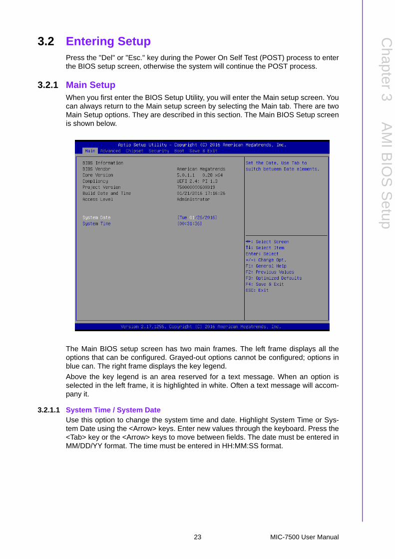
3.2.1 Main SetupWhen you first enter the BIOS Setup Utility, you will enter the Main setup screen. Youcan always return to the Main setup screen by selecting the Main tab. There are twoMain Setup options. They are described in this section. The Main BIOS Setup screenis shown below.
The Main BIOS setup screen has two main frames. The left frame displays all theoptions that can be configured. Grayed-out options cannot be configured; options inblue can. The right frame displays the key legend.
Above the key legend is an area reserved for a text message. When an option isselected in the left frame, it is highlighted in white. Often a text message will accom-pany it.
3.2.1.1 System Time / System DateUse this option to change the system time and date. Highlight System Time or Sys-tem Date using the <Arrow> keys. Enter new values through the keyboard. Press the<Tab> key or the <Arrow> keys to move between fields. The date must be entered inMM/DD/YY format. The time must be entered in HH:MM:SS format.
23 MIC-7500 User Manual
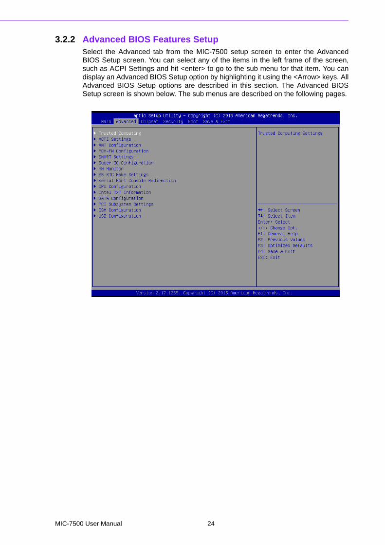
3.2.2 Advanced BIOS Features SetupSelect the Advanced tab from the MIC-7500 setup screen to enter the AdvancedBIOS Setup screen. You can select any of the items in the left frame of the screen,such as ACPI Settings and hit <enter> to go to the sub menu for that item. You candisplay an Advanced BIOS Setup option by highlighting it using the <Arrow> keys. AllAdvanced BIOS Setup options are described in this section. The Advanced BIOSSetup screen is shown below. The sub menus are described on the following pages.
MIC-7500 User Manual 24

Chapter 3
AM
I BIO
SS
etup
3.2.2.1 Trusted Computing
Security Device SupportThis item allows users to enable or disable “Security Device Support”.
3.2.2.2 ACPI Settings
25 MIC-7500 User Manual

Enable ACPI Auto ConfigurationThis item allows users to enable or disable “ACPI Auto Configuration”.
Enable Hibernation This item allows users to enable or disable “Hibernation”.
ACPI Sleep StateThis item allows users to set ACPI mode S3 (Suspend to RAM) or to Disable“ACPI Sleep State”.
PowerOn by ModemThis item allows users to enable or disable “PowerOn by Modem”.
MIC-7500 User Manual 26

Chapter 3
AM
I BIO
SS
etup
3.2.2.3 AMT Configuration
Intel AMTThis item allows users to enable or disable "Intel AMT".
BIOS Hotkey PressedThis item allows users to enable or disable for "BIOS Hotkey Pressed".
MEBx Selection ScreenThis item allows users to enable or disable for "MEBx Selection Screen".
Hide Un-Configure ME Confirmation PromptThis item allows users to enable or disable for "Hide Un-Configure ME Confir-mation Prompt".
MEBx Debug Message OutputThis item allows users to enable or disable for "MEBx Debug Message Output".
Un-Configure METhis item allows users to enable or disable for "Un-Configure ME".
Amt Wait TimerSet timer to wait before sending ASF_GET_Boot_Options
ASFThis item allows users to enable or disable for "ASF".
Activate Remote Assistance ProcessThis item allows users to enable or disable for "Activate Remote Assistance Pro-cess".
USB ConfigureThis item allows users to enable or disable for "USB Configure".
PET ProgressThis item allows users to enable or disable for "PET Progress".
WatchDogThis item allows users to enable or disable for "WatchDog".
27 MIC-7500 User Manual

3.2.2.4 PCH-FW Configuration
Firmware Update Configuration
Me FW Image Re-FlashThis item allows users to enable or disable for "Me FW Image Re-Flash".
MIC-7500 User Manual 28
Chapter 3
AM
I BIO
SS
etup
3.2.2.5 SMART Settings
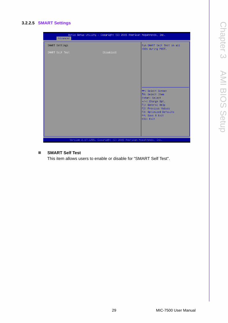
SMART Self TestThis item allows users to enable or disable for ”SMART Self Test".
29 MIC-7500 User Manual

3.2.2.6 Support IO ConfigurationMIC-7500 supports 2xRS-232/422/485 & 2-RS-232 in front side. There has 2 moreRS-232 (Serial Port 5 & 6) signal in M/B, you can find a cable at accessory box.
MIC-7500 User Manual 30
Chapter 3
AM
I BIO
SS
etup
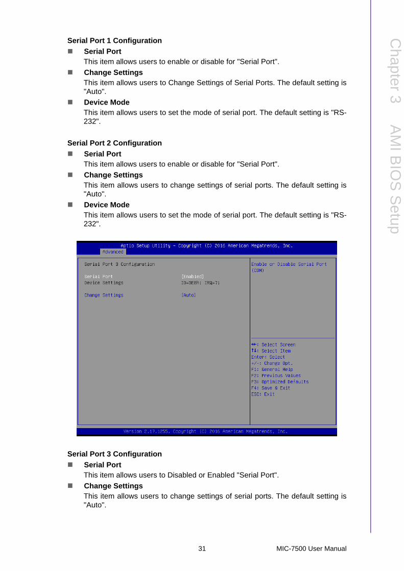
Serial Port 1 Configuration
Serial PortThis item allows users to enable or disable for "Serial Port".
Change SettingsThis item allows users to Change Settings of Serial Ports. The default setting is"Auto".
Device ModeThis item allows users to set the mode of serial port. The default setting is "RS-232".
Serial Port 2 Configuration
Serial PortThis item allows users to enable or disable for "Serial Port".
Change SettingsThis item allows users to change settings of serial ports. The default setting is"Auto".
Device ModeThis item allows users to set the mode of serial port. The default setting is "RS-232".
Serial Port 3 Configuration
Serial PortThis item allows users to Disabled or Enabled "Serial Port".
Change SettingsThis item allows users to change settings of serial ports. The default setting is"Auto".
31 MIC-7500 User Manual

Serial Port 4 Configuration
Serial PortThis item allows users enable or disable for "Serial Port".
Change SettingsThis item allows users to change settings of serial ports. The default setting is"Auto".
Serial Port 5 Configuration
Serial PortThis item allows users enable or disable for "Serial Port".
Change SettingsThis item allows users to change settings of serial ports. The default setting is"Auto".
Serial Port 6 Configuration
Serial PortThis item allows users to enable or disable for "Serial Port".
Change SettingsThis item allows users to change settings of serial ports. The default setting is"Auto".
MIC-7500 User Manual 32
Chapter 3
AM
I BIO
SS
etup
3.2.2.7 HW Monitor
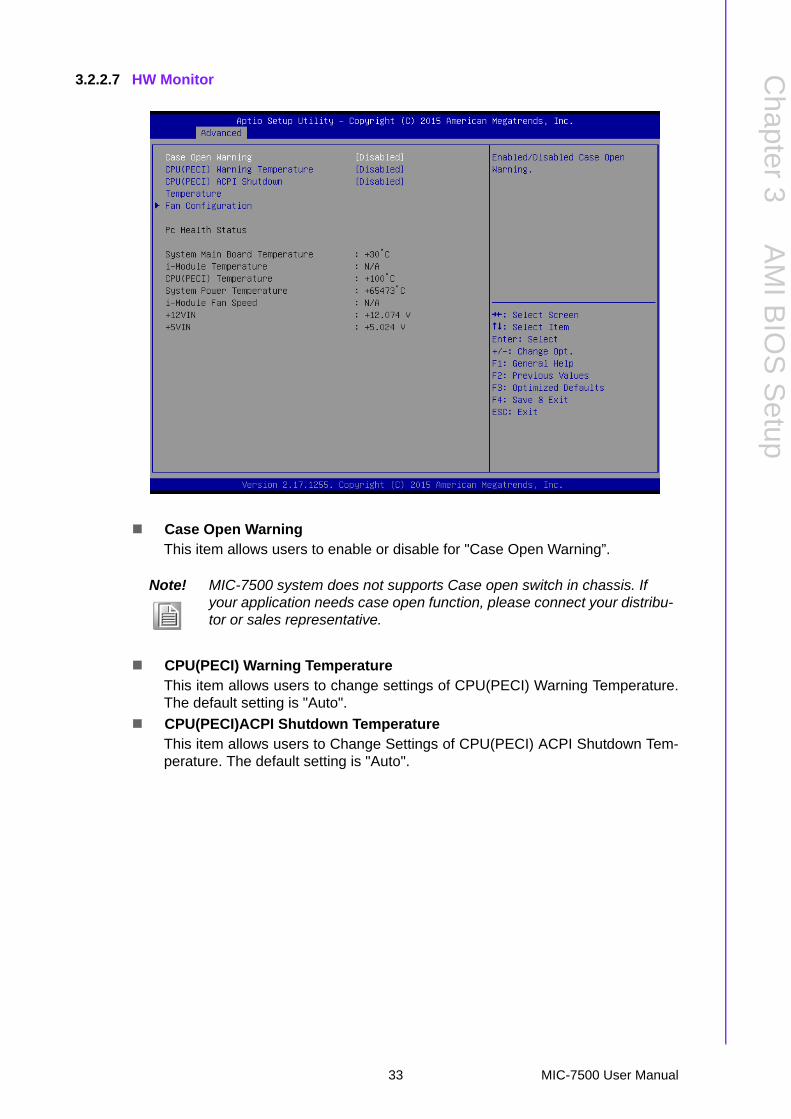
Case Open WarningThis item allows users to enable or disable for "Case Open Warning”.
CPU(PECI) Warning TemperatureThis item allows users to change settings of CPU(PECI) Warning Temperature.The default setting is "Auto".
CPU(PECI)ACPI Shutdown TemperatureThis item allows users to Change Settings of CPU(PECI) ACPI Shutdown Tem-perature. The default setting is "Auto".
Note! MIC-7500 system does not supports Case open switch in chassis. If your application needs case open function, please connect your distribu-tor or sales representative.
33 MIC-7500 User Manual

Fan Configuration
i-Module FANThis item allows users to Manual Mode or SmartFan Mode for i-Module.
PC Health StatusMIC-7500 system has design-in temperature sensor to monitor system tempera-ture. You can clear to read M/B, Power board, or i-Module Temperature status.
Note! MIC-7500 system does not supports FAN. This function only workable in MIC-7500 with i-Module +FAN.
MIC-7500 User Manual 34

Chapter 3
AM
I BIO
SS
etup
3.2.2.8 S5 RTC Wake Settings
Wake system from S5This item allows users to enable or disable for "Wake system from S5".
35 MIC-7500 User Manual
3.2.2.9 Serial Port Console Redirection
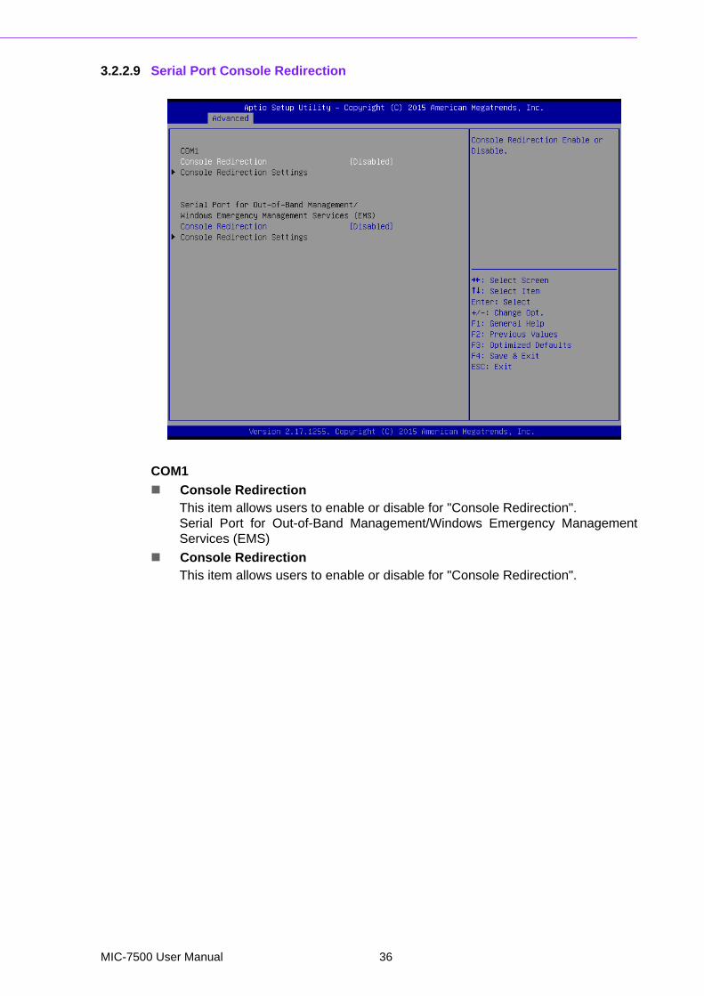
COM1
Console RedirectionThis item allows users to enable or disable for "Console Redirection".Serial Port for Out-of-Band Management/Windows Emergency ManagementServices (EMS)
Console RedirectionThis item allows users to enable or disable for "Console Redirection".
MIC-7500 User Manual 36

Chapter 3
AM
I BIO
SS
etup
3.2.2.10 CPU Configuration
37 MIC-7500 User Manual

Active Processor CoresThis item allows users to set different modes of "Active Processor Cores". Thedefault setting is All.
Intel Virtualization TechnologyThis item allows users to enable or disable for "Intel Virtualization Technology".
Hardware PrefetcherThis item allows users to enable or disable for "Hardware Prefetcher".
Adjacent Cache Line PrefetchThis item allows users to enable or disable for "Adjacent Cache Line Prefetch".
CPU AESThis item allows users to enable or disable for "CPU AES".
Boot performance modeThis item allows users to set Max Non-Turbo Performance or Turbo Perfor-mance for "Boot performance mode".
Intel(R) SpeedStep(tm)This item allows users to enable or disable for "Intel(R) SpeedStep(tm)".
Turbo ModeThis item allows users to enable or disable for "Turbo Mode".
Intel TXT(LT) SupportThis item allows users to enable or disable for "Intel TXT(LT) Support".
MIC-7500 User Manual 38

Chapter 3
AM
I BIO
SS
etup
3.2.2.11 Intel TXT Information
3.2.2.12 SATA Controller
39 MIC-7500 User Manual
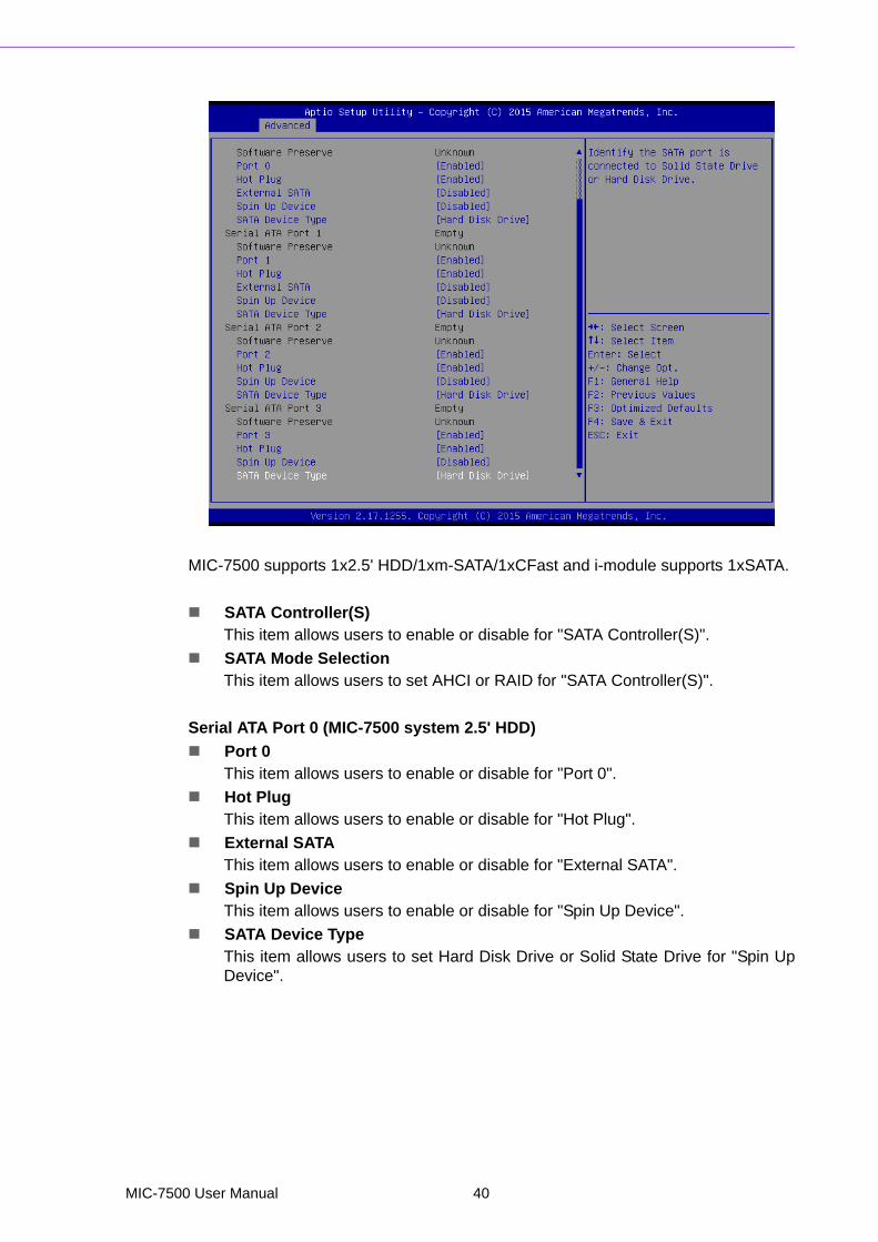
MIC-7500 supports 1x2.5' HDD/1xm-SATA/1xCFast and i-module supports 1xSATA.
SATA Controller(S)This item allows users to enable or disable for "SATA Controller(S)".
SATA Mode SelectionThis item allows users to set AHCI or RAID for "SATA Controller(S)".
Serial ATA Port 0 (MIC-7500 system 2.5' HDD)
Port 0This item allows users to enable or disable for "Port 0".
Hot PlugThis item allows users to enable or disable for "Hot Plug".
External SATAThis item allows users to enable or disable for "External SATA".
Spin Up DeviceThis item allows users to enable or disable for "Spin Up Device".
SATA Device TypeThis item allows users to set Hard Disk Drive or Solid State Drive for "Spin UpDevice".
MIC-7500 User Manual 40
Chapter 3
AM
I BIO
SS
etup
Serial ATA Port 1 (MIC-7 series i-module 2.5' HDD)
Port 1This item allows users to enable or disable for "Port 1".
Hot PlugThis item allows users to enable or disable for "Hot Plug".
External SATAThis item allows users to enable or disable for "External SATA".
Spin Up DeviceThis item allows users to enable or disable for "Spin Up Device".
SATA Device Type-This item allows users to Hard Disk Drive or Solid State Drive for "Spin UpDevice".
Serial ATA Port 2 (MIC-7500 CFast)
Port 2This item allows users to enable or disable for "Port 2".
Hot PlugThis item allows users to enable or disable for "Hot Plug".
Spin Up DeviceThis item allows users to enable or disable for "Spin Up Device".
SATA Device TypeThis item allows users to set Hard Disk Drive or Solid State Drive for "Spin UpDevice".
Serial ATA Port 3 (MIC-7500 m-SATA by Mini-PCIe socket)
Port 3This item allows users to enable or disable for "Port 3".
Hot PlugThis item allows users to enable or disable for "Hot Plug".
Spin Up DeviceThis item allows users to enable or disable for "Spin Up Device".
SATA Device TypeThis item allows users to set Hard Disk Drive or Solid State Drive for "Spin UpDevice".
41 MIC-7500 User Manual
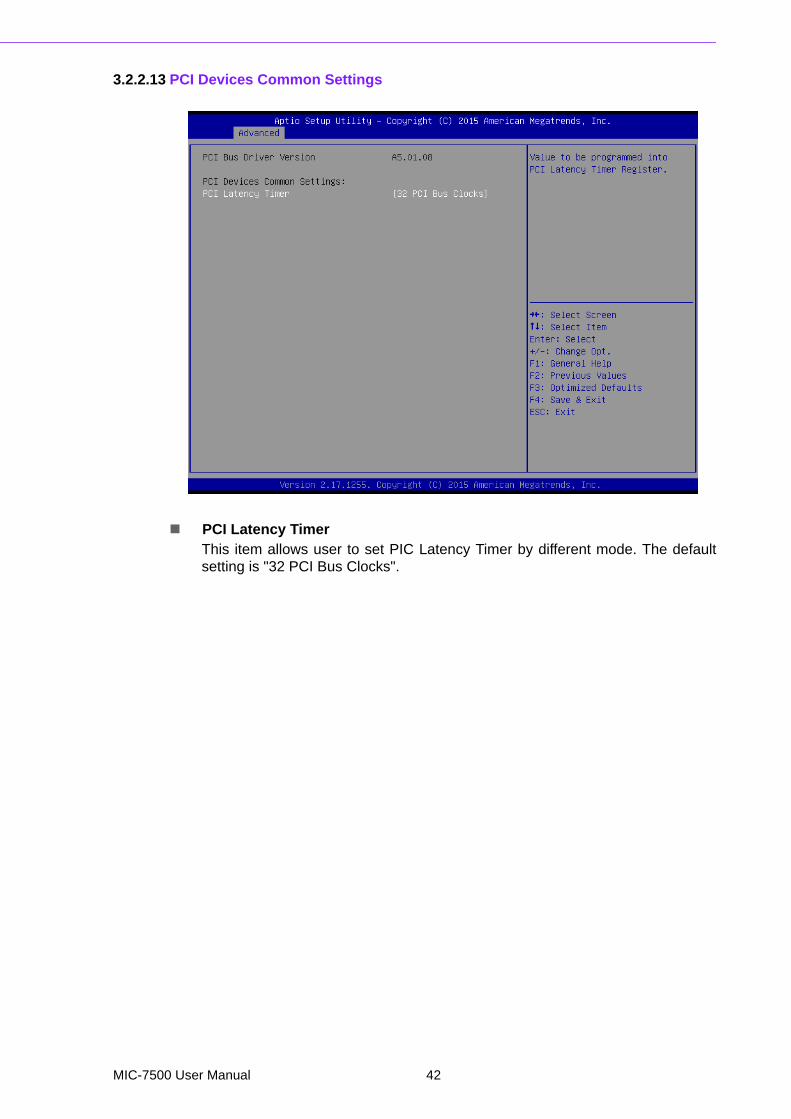
3.2.2.13 PCI Devices Common Settings
PCI Latency TimerThis item allows user to set PIC Latency Timer by different mode. The defaultsetting is "32 PCI Bus Clocks".
MIC-7500 User Manual 42

Chapter 3
AM
I BIO
SS
etup
3.2.2.14 CSM Configuration
CSM SupportThis item allows users to enable or disable for "CSM Support".
GateA20 ActiveThis item allows users to setUpon Request or Always for "GateA20 Active".
Option ROM MessagesThis item allows users to setForce BIOS or Keep Current for "Option ROM Mes-sages".
INT19 Trap ResponseThis item allows users to setImmediate or Postponed for "INT19 TrapResponse".
Boot option filterThis item allows users to set UEFI and Legacy or Legacy only or UEFI only for"Boot option filter".
NetworkThis item allows users to set Do not launch or Legacy for "Network".
StorageThis item allows users to set Do not launch or UEFI or Legacy for "Storage".
VideoThis item allows users to set Do not launch or UEFI or Legacy for "Video".
Other PCI devicesThis item allows users to set Do not launch or UEFI or Legacy for "Other PCIdevices".
43 MIC-7500 User Manual
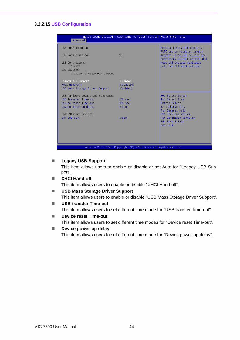
3.2.2.15 USB Configuration
Legacy USB SupportThis item allows users to enable or disable or set Auto for "Legacy USB Sup-port".
XHCI Hand-offThis item allows users to enable or disable "XHCI Hand-off".
USB Mass Storage Driver SupportThis item allows users to enable or disable "USB Mass Storage Driver Support".
USB transfer Time-outThis item allows users to set different time mode for "USB transfer Time-out".
Device reset Time-outThis item allows users to set different time modes for "Device reset Time-out".
Device power-up delayThis item allows users to set different time mode for "Device power-up delay".
MIC-7500 User Manual 44

Chapter 3
AM
I BIO
SS
etup
3.2.3 Chipset
System Agent (SA) Configuration
45 MIC-7500 User Manual

VT-dThis item allows users to enable or disable for "VT-d".
Graphics Configuration
Graphics Turbo IMON CurrentGraphics turbo IMON current values supported (14-31).
Primary DisplayThis item allows users to set Auto or IGFX or PEG or PCIE for "Primary Dis-play".
Primary PEGThis item allows users to set Auto or PEG11 or PEG 12 for "Primary PEG".
Internal GraphicsThis item allows users to set Auto or Disabled or Enabled for "Internal Graph-ics".
MIC-7500 User Manual 46
Chapter 3
AM
I BIO
SS
etup
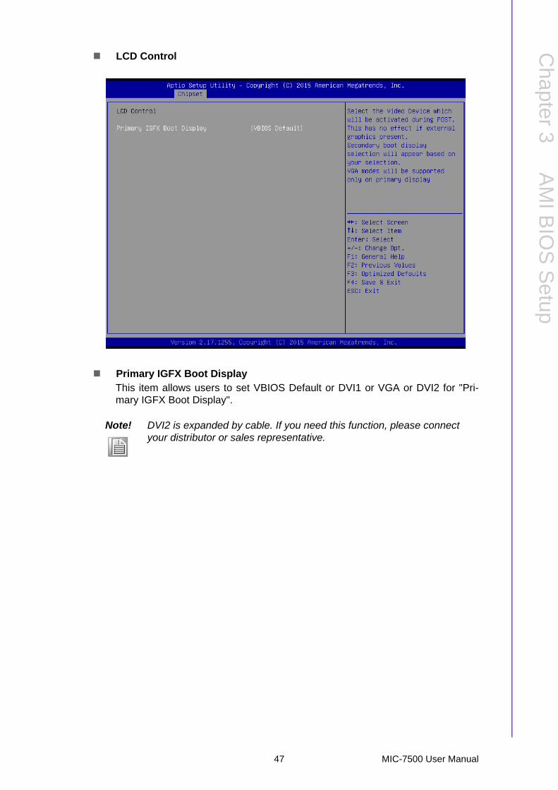
LCD Control
Primary IGFX Boot DisplayThis item allows users to set VBIOS Default or DVI1 or VGA or DVI2 for "Pri-mary IGFX Boot Display".
Note! DVI2 is expanded by cable. If you need this function, please connect your distributor or sales representative.
47 MIC-7500 User Manual

PEG Port Configuration
This item allows user to set CPU PCI Expansion x16 GEN3.
Note! Skylake-H CPU PCI Expansion x16 signals can be cut to x8, x4, x4 sig-nal or x8, x8signal. Corresponding setting item are as follows:
PEG 0 : 1 : 0 : for PCIEx16 or PCIEx8
PEG 0 : 1 : 1 : for PCIEx8 or PCIEx4
PEG 0 : 1 : 2 : for PCIEx4
MIC-7500 User Manual 48
Chapter 3
AM
I BIO
SS
etup
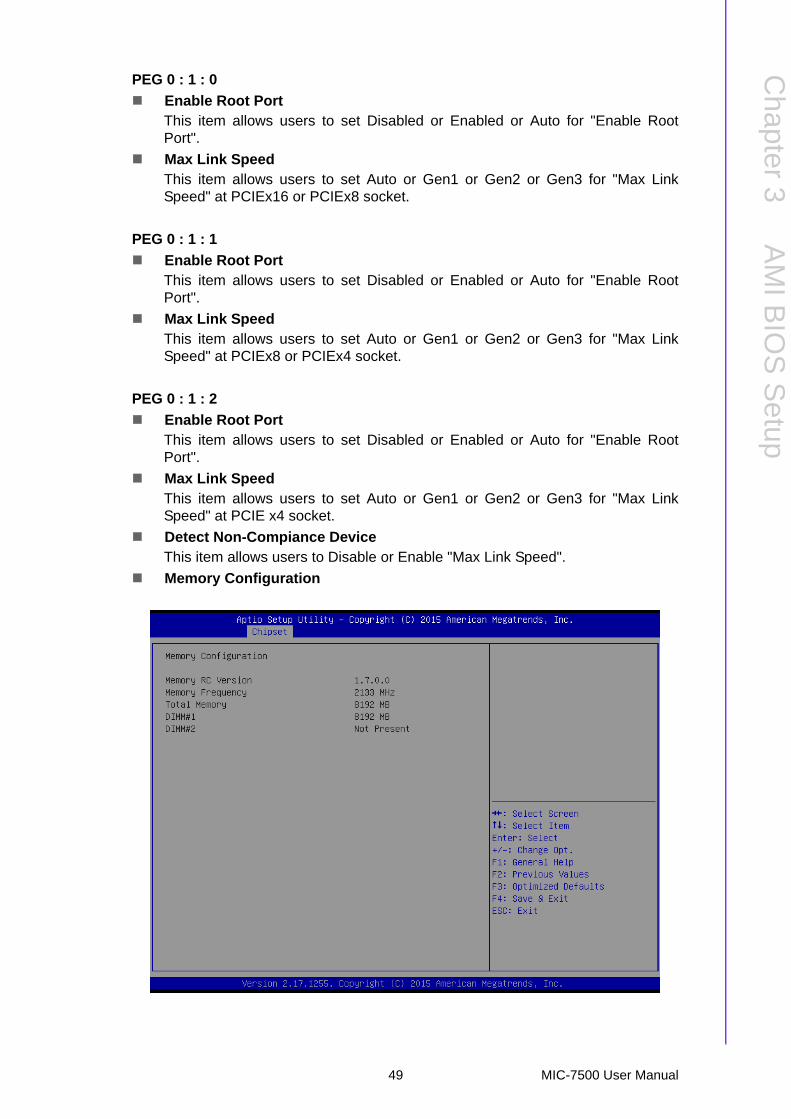
PEG 0 : 1 : 0
Enable Root PortThis item allows users to set Disabled or Enabled or Auto for "Enable RootPort".
Max Link Speed This item allows users to set Auto or Gen1 or Gen2 or Gen3 for "Max LinkSpeed" at PCIEx16 or PCIEx8 socket.
PEG 0 : 1 : 1
Enable Root PortThis item allows users to set Disabled or Enabled or Auto for "Enable RootPort".
Max Link Speed This item allows users to set Auto or Gen1 or Gen2 or Gen3 for "Max LinkSpeed" at PCIEx8 or PCIEx4 socket.
PEG 0 : 1 : 2
Enable Root PortThis item allows users to set Disabled or Enabled or Auto for "Enable RootPort".
Max Link Speed This item allows users to set Auto or Gen1 or Gen2 or Gen3 for "Max LinkSpeed" at PCIE x4 socket.
Detect Non-Compiance DeviceThis item allows users to Disable or Enable "Max Link Speed".
Memory Configuration
49 MIC-7500 User Manual
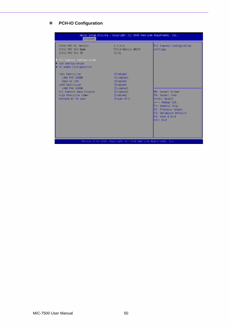
PCH-IO Configuration
MIC-7500 User Manual 50

Chapter 3
AM
I BIO
SS
etup
3.2.3.1 PCI Express Configuration
Note! This item allows users to set PCH PCI Express signal, including PCIe x4 (or PCIe x1) or Mini-PCIE A or Mini-PCIE B. Corresponding setting item are as follows:
-->PCI Express Root Port 5: i-module PCIe x4 or PCIe x1
-->PCI Express Root Port 13: Mini PCIe A
-->PCI Express Root Port 16: Mini PCIe B
51 MIC-7500 User Manual

PCI Express Root Port 5
PCI Express Root Port5
PCI Express Root Port 5This item allows users to disable or enable "PCI Express Root Port 5".
Advanced Error ReportingThis item allows users to disable or enable for "Advanced Error Reporting".
PCIe SpeedThis item allows users to set Auto or Gen1 or Gen2 or Gen3 for "PCIe Speed".
Note! This item allows users to set i-module PCIe x4 (or PCIe x1 socket).
MIC-7500 User Manual 52

Chapter 3
AM
I BIO
SS
etup
Detect Non-Compliant DeviceThis item allows users to disable or enable "Detect Non-Compliance Device".
PCI Express Root Port 13
PCI Express Root Port 13This item allows users to disable or enable "PCI Express Root Port 13".
Advanced Error ReportingThis item allows users to disable or enable "Advanced Error Reporting”.
PCIe SpeedThis item allows users to set Auto or Gen1 or Gen2 or Gen3 for "PCIe Speed".
Detect Non-Compliance DeviceThis item allows users to disable or enable “Detect Non-Compliance Device”.
Note! Mini-PCIE socket only supports to Gen 2.
53 MIC-7500 User Manual
Detect Non-Compliant DeviceThis item allows users to disable or enable “Detect Non-Compliance Device".
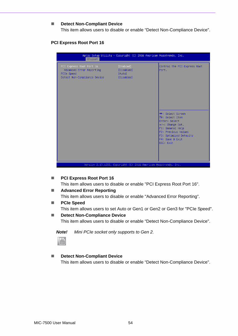
PCI Express Root Port 16
PCI Express Root Port 16This item allows users to disable or enable "PCI Express Root Port 16".
Advanced Error ReportingThis item allows users to disable or enable "Advanced Error Reporting”.
PCIe SpeedThis item allows users to set Auto or Gen1 or Gen2 or Gen3 for "PCIe Speed".
Detect Non-Compliance DeviceThis item allows users to disable or enable “Detect Non-Compliance Device".
Detect Non-Compliant DeviceThis item allows users to disable or enable “Detect Non-Compliance Device".
Note! Mini PCIe socket only supports to Gen 2.
MIC-7500 User Manual 54
Chapter 3
AM
I BIO
SS
etup
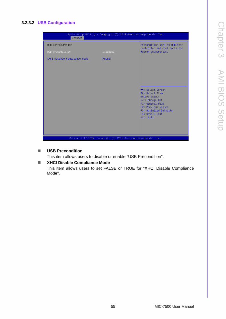
3.2.3.2 USB Configuration
USB PreconditionThis item allows users to disable or enable "USB Precondition".
XHCI Disable Compliance Mode This item allows users to set FALSE or TRUE for "XHCI Disable ComplianceMode".
55 MIC-7500 User Manual

3.2.3.3 HD Audio Configuration
HD AudioThis item allows users to Disable or Enabled or set Auto for "HD Audio".
MIC-7500 User Manual 56

Chapter 3
AM
I BIO
SS
etup
LAN 1 ControllerThis item allows users to disable or enable "LAN 1 Controller".
LAN1 PXE OpROMThis item allows users to disable or enable "LAN1 PXE OpROM".
Wake on LANThis item allows users to set LAN1 Disabled or Enabled for "Wake on LAN".
LAN 2 ControllerThis item allows users to disable or enable "LAN 2 Controller".
LAN2 PXE OpROMThis item allows users to disable or enable "LAN 2 PXE OpROM".
PCI Express Wake DisableThis item allows users to disable or enable "PCI Express Wake Disable".
High Precision TimerThis item allows users to disable or enable "High Precision Timer".
Restore AC PW LossThis item allows users to set Power On or Power Off or Last State for "RestoreAC PW Loss".
57 MIC-7500 User Manual

3.2.4 Security
Administrator PasswordThis item allows users to set "Administrator Password" if desired.
User PasswordThis item allows users to set "User Password" if desired.
MIC-7500 User Manual 58

Chapter 3
AM
I BIO
SS
etup
3.2.5 Boot
Setup Prompt TimeoutNumber of Seconds to wait for setup activation kay. 65535 (0xFFFF) meansindefinite waiting.
Bootup NumLock StateThis item allows users to set "Bootup NumLock State" either On or Off.
Quiet BootThis item allows users to disable or enable "Quiet Boot".
Boot Option Priorities
– Boot Option #1– Boot Option #2
Note! These items will display based on how many devices are attached.
59 MIC-7500 User Manual

3.2.6 Save & Exit
Save Changes and ExitThis item allows users to Save Changes and Exit.
Discard Changes and ExitThis item allows users to Discard Changes and Exit.
Save Changes and ResetThis item allows users to Save Changes and Reset.
Discard Changes and ResetThis item allows users to Discard Changes and Reset.
Save ChangesThis item allows users to Save Changes.
Discard ChangesThis item allows users to Discard Changes.
Restore DefaultsThis item allows users to restore factory defaults.
Save as User DefaultsThis item allows users to Save as User Defaults.
Restore User DefaultsThis item allows users to Restore User Defaults.
Launch EFI Shell from file system deviceAttempts to Launch EFI Shell application (Shell.efi) form one of the available filesystem devices.
MIC-7500 User Manual 60

Chapter 4
4 Software InstallationThis chapter introduces driverinstallation.
4.1 Chipset Software Installation Utility
4.1.1 Before you beginTo facilitate the installation of the enhanced display drivers and utility software, readthe instructions in this chapter carefully. The drivers for the MIC-7500 are located onthe software installation CD.
Before you begin, it is important to note that most display drivers need to have the rel-evant software application already installed in the system prior to installing theenhanced display drivers. In addition, many of the installation procedures assumethat you are familiar with both the relevant software applications and operating sys-tem commands. Review the relevant operating system commands and the pertinentsections of your application software’s user manual before performing the installation.
4.1.2 IntroductionThe Intel® Chipset Software Installation (CSI) utility installs the Windows INF filesthat outline to the operating system how the chipset components will be configured.This is needed for the proper functioning of the following features:
Core PCI PnP services Serial ATA interface support USB 1.1/2.0 support Identification of Intel chipset components in the Device Manager.
Advantech supports a powerful Windows 7 OS that includes USB3.0 (EFI OS notsupported). It can help you install Win7 OS easily. If you need this option, please con-tact your distributor or sales representative.
Note! The files on the software installation CD are compressed. Do not attempt to install the drivers by copying the files manually. You must use the supplied SETUP program to install the drivers.
Note! The chipset driver is used for the following versions of Windows, and it has to be installed before installing all the other drivers:
Windows 10 (64bit) Windows 8.1 (64-bit) Windows 7 (32-bit) Windows 7 (64-bit)
Caution! Intel® Skylake Platform does not include a USB3.0 driver. The user can use a SATA interface driver (SATA CD-RAM or CFast or m-SATA) to install Windows 7 OS.
MIC-7500 User Manual 62
Chapter 4
Softw
areInstallation
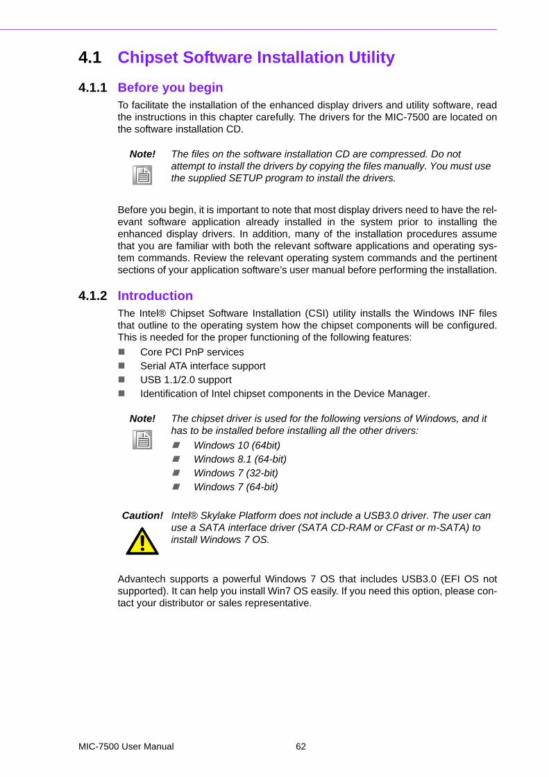
4.1.3 Windows 10 / Windows 8.1/ Windows 71. Put the driver CD into the system's CD-ROM drive. You will see driver folder
items. Select "01 Chipset" folder. In CSI folder, click the executable file to com-plete driver installation.
2. Click setup to execute program.
4.2 Integrated Graphic Device Setup
4.2.1 IntroductionThe 4th Gen Intel® Core™ i processors are embedded with integrated graphics con-troller. You need to install the VGA driver to enable this function, which includes thefollowing features:
Optimized integrated graphic solution: Intel® Graphics Flexible Display Inter-face supports versatile display options and 32-bit 3D graphics engine for dual independent displays, enhanced display modes for widescreen flat panels for extended, twin, and cloned dual display modes, and optimized 3D support deliv-ers an intensive and realistic visual experience.
Caution! Intel® Graphic Device does not support Windows 10 (32bit) and Win-dows 8.1 (32.bit)
63 MIC-7500 User Manual
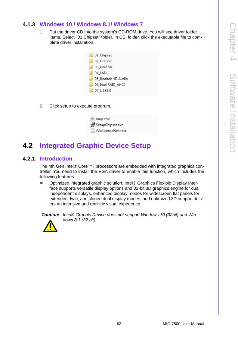
4.2.2 Windows 10 /Windows 8.1 /Windows 7 Driver Setup
Insert the driver CD into your system's CD-ROM drive. You can see the driver folders.Navigate to the "02 Graphic" folder and click the executable file to complete theinstallation of the drivers for Windows 7, Windows 8 and Windows 10.
4.3 Intel® ME
4.3.1 IntroductionThe Intel® ME software components that need to be installed depend on the sys-tem's specific hardware and firmware features. The installer detects the system'scapabilities and installs the relevant drivers and applications.
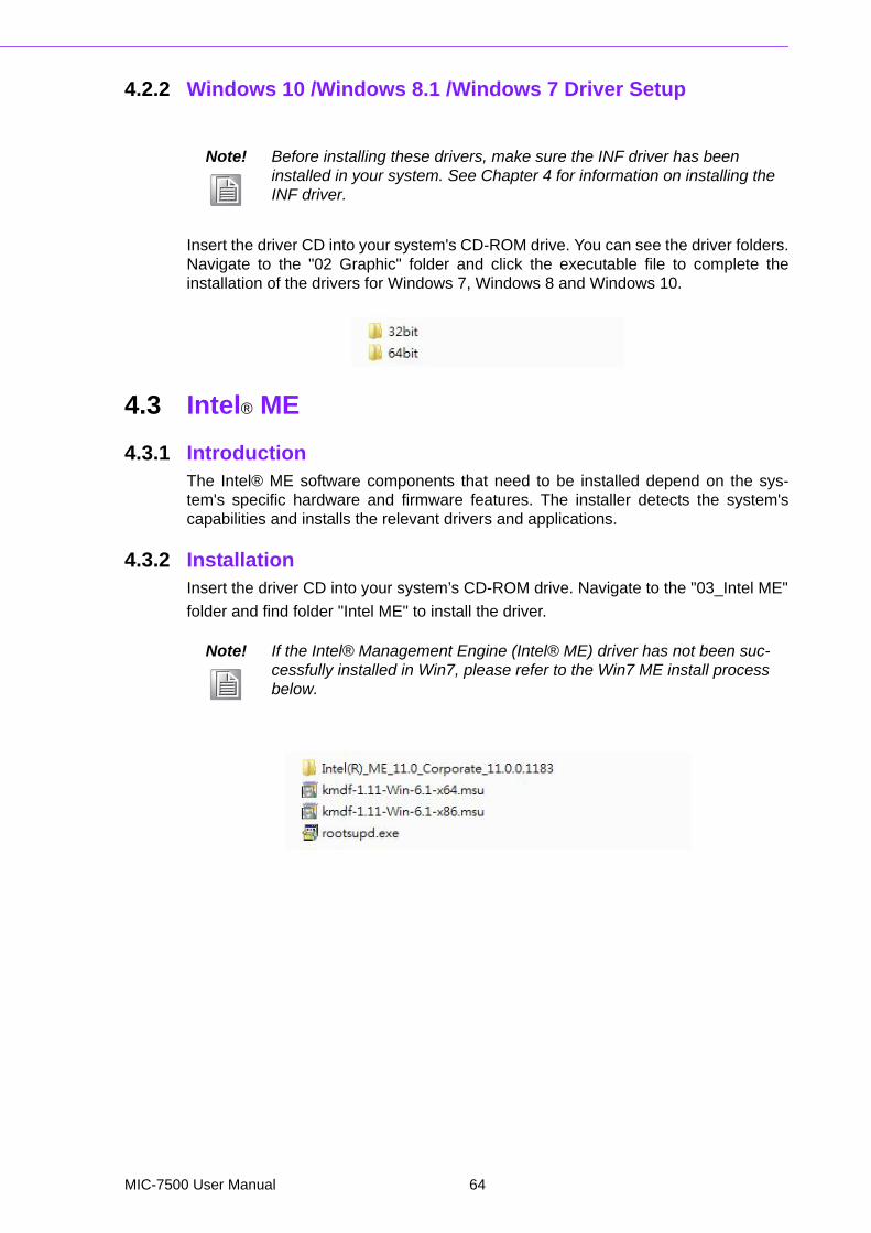
4.3.2 InstallationInsert the driver CD into your system’s CD-ROM drive. Navigate to the "03_Intel ME"
folder and find folder "Intel ME" to install the driver.
Note! Before installing these drivers, make sure the INF driver has been installed in your system. See Chapter 4 for information on installing the INF driver.
Note! If the Intel® Management Engine (Intel® ME) driver has not been suc-cessfully installed in Win7, please refer to the Win7 ME install process below.
MIC-7500 User Manual 64

Chapter 4
Softw
areInstallation
4.3.3 Install Intel® ME for Windows 7Please follow this processer to install Intel® ME for Windows 7.
1. Install hot fix first.
2. Install ME.
3. Install rootsupd.exe.
4.4 LAN Configuration
4.4.1 IntroductionThe MIC-7500 has dual Gigabit Ethernet LANs via dedicated PCI Express x1 lanes(Intel® I219LM (LAN1) and I210IT (LAN2)) that offer bandwidth of up to 500 MB/sec,eliminating the bottleneck of network data flow and incorporating Gigabit Ethernet at1000 Mbps.
4.4.2 Features 10/100/1000Base-T Ethernet controller 10/100/1000Base-T triple-speed MAC Full duplex at 10, 100, or 1000 Mbps and half duplex at 10 or 100 Mbps Wake-on-LAN (WOL) support PCIe x1 host interface
65 MIC-7500 User Manual
4.4.3 Installation
The integrated Intel® gigabit Ethernet controller supports all major network operatingsystems. However, the installation procedure varies with different operating systems.In the following sections, refer to the one that provides the driver setup procedure forthe operating system you are using.
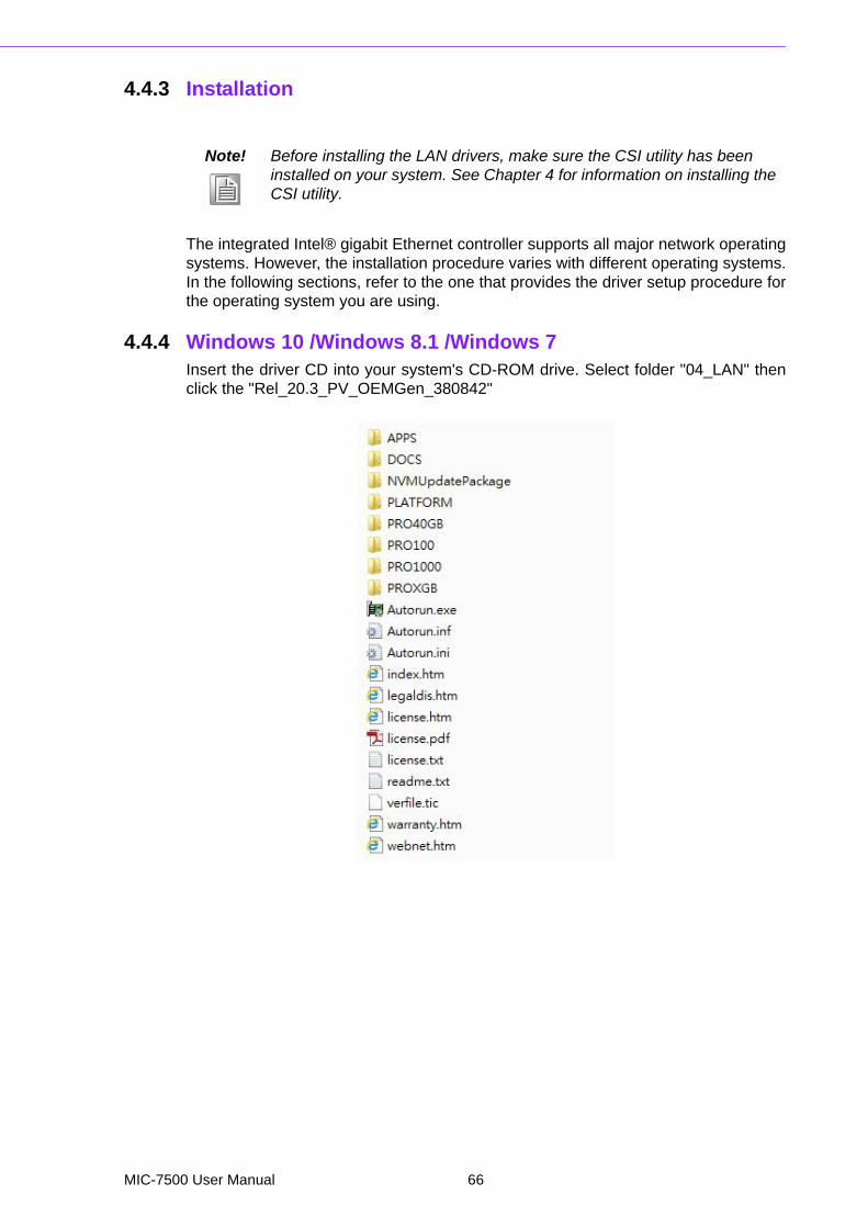
4.4.4 Windows 10 /Windows 8.1 /Windows 7Insert the driver CD into your system's CD-ROM drive. Select folder "04_LAN" thenclick the "Rel_20.3_PV_OEMGen_380842"
Note! Before installing the LAN drivers, make sure the CSI utility has been installed on your system. See Chapter 4 for information on installing the CSI utility.
MIC-7500 User Manual 66

Chapter 4
Softw
areInstallation
4.5 SATA RAID Setup
4.5.1 IntroductionTo support demanding disk I/O, Intel® Q170 chipset integrates six Serial ATA control-lers with software RAID 0, 1, 5, 10 capabilities.
RAID 0 striping increases the storage performance and is designed to speed up data
transfer rates for disk-intensive applications.
RAID 1 mirroring protects valuable data that might be lost in the event of a hard drive
failure.
RAID 5 array contains three or more hard drives where the data is divided into man-ageable blocks called strips. Parity is a mathematical method for recreating data thatwas lost from a single drive, which increases fault-tolerance. The data and parity arestriped across all the hard drives in the array. The parity is striped in a rotatingsequence to reduce bottlenecks associated with the parity calculations.
RAID 10 array uses four hard drives to create a combination of RAID levels 0 and 1.The data is striped across a two-drive array forming the RAID 0 component. Each ofthe drives in the RAID 0 array is then mirrored by a RAID 1 component.
4.5.2 SATA RAID Driver and Utility SetupThe installation utility is in the CD’s “06_Intel RAID_AHCI” folder. Go to the directoryof the CD and follow these steps to install.
4.6 Install USB3.0
4.6.1 IntroductionMIC-7500 provides 8x USB 3.0 and the data transfer rate of USB3.0 (5Gb/s) is 10times to USB2.0 (480 Mbps).
Insert the driver CD into your system’s CD-ROM drive. Navigate to the "07 USB3.0"to install the drier.
Note! Please install “.NET 4.5” before installing “Intel Rapid Storage Technol-ogy”.
67 MIC-7500 User Manual

MIC-7500 User Manual 68

Appendix A
A Programming the Watchdog Timer
A.1 Programming the Watchdog TimerThe MIC-7500's watchdog timer can be used to monitor system software operationand take corrective action if the software fails to function within the programmedperiod. This section describes the operation of the watchdog timer and how to pro-gram it.
A.1.1 Watchdog Timer OverviewThe watchdog timer is built into the super I/O controller NCT6106D. It provides thefollowing user-programmable functions:
It can be enabled and disabled by user program Timer can be set from 1 to 255 seconds or 1 to 255 minutes Generates an interrupt or resets signal if the software fails to reset the timer
before time-out
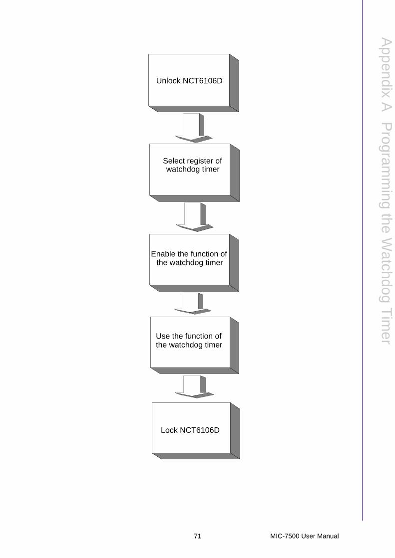
A.1.2 Programming the Watchdog TimerThe I/O port address of the watchdog timer is 2E (hex) and 2F (hex). 2E (hex) is theaddress port. 2F (hex) is the data port. You must first assign the address of registerby writing an address value into address port 2E (hex), then write/read data to/fromthe assigned register through data port 2F (hex).
MIC-7500 User Manual 70
Appendix A
Program
ming
theW
atchdogT
imer
Select register of watchdog timer
Enable the function ofthe watchdog timer
Use the function ofthe watchdog timer
Unlock NCT6106D
Lock NCT6106D
71 MIC-7500 User Manual
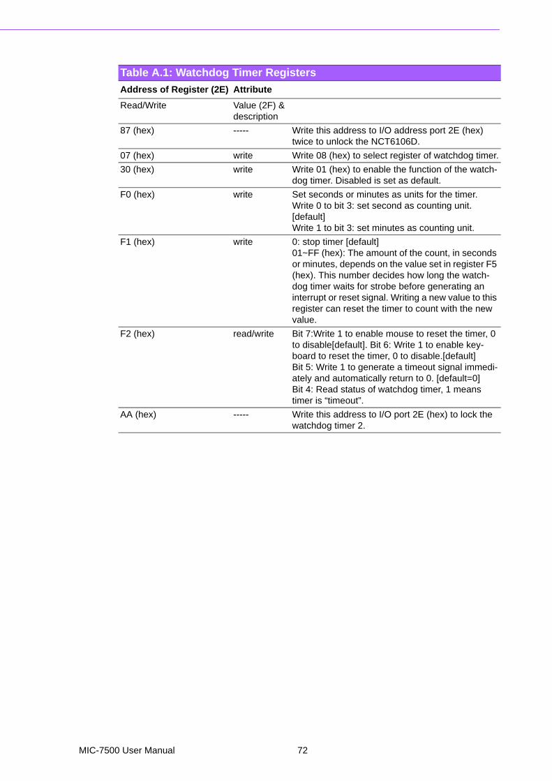
Table A.1: Watchdog Timer Registers
Address of Register (2E) Attribute
Read/Write Value (2F) &description
87 (hex) ----- Write this address to I/O address port 2E (hex) twice to unlock the NCT6106D.
07 (hex) write Write 08 (hex) to select register of watchdog timer.
30 (hex) write Write 01 (hex) to enable the function of the watch-dog timer. Disabled is set as default.
F0 (hex) write Set seconds or minutes as units for the timer.Write 0 to bit 3: set second as counting unit. [default]Write 1 to bit 3: set minutes as counting unit.
F1 (hex) write 0: stop timer [default]01~FF (hex): The amount of the count, in seconds or minutes, depends on the value set in register F5 (hex). This number decides how long the watch-dog timer waits for strobe before generating an interrupt or reset signal. Writing a new value to this register can reset the timer to count with the new value.
F2 (hex) read/write Bit 7:Write 1 to enable mouse to reset the timer, 0 to disable[default]. Bit 6: Write 1 to enable key-board to reset the timer, 0 to disable.[default] Bit 5: Write 1 to generate a timeout signal immedi-ately and automatically return to 0. [default=0]Bit 4: Read status of watchdog timer, 1 means timer is “timeout”.
AA (hex) ----- Write this address to I/O port 2E (hex) to lock the watchdog timer 2.
MIC-7500 User Manual 72

Appendix A
Program
ming
theW
atchdogT
imer
A.1.3 Example Program1. Enable watchdog timer and set 10 sec. as timeout interval;-----------------------------------------------------------
Mov dx,2eh ; Unlock NCT6106D
Mov al,87h
Out dx,al
Out dx,al
;-----------------------------------------------------------
Mov al,07h ; Select registers of watchdog timer
Out dx,al
Inc dx
Mov al,08h
Out dx,al
;-----------------------------------------------------------
Dec dx ; Enable the function of watchdog timer
Mov al,30h
Out dx,al
Inc dx
Mov al,01h
Out dx,al
;-----------------------------------------------------------
Dec dx ; Set second as counting unit
Mov al,0f0h
Out dx,al
Inc dx
In al,dx
And al,not 08h
Out dx,al
;-----------------------------------------------------------
Dec dx ; Set timeout interval as 10 seconds and start counting
Mov al,0f1h
Out dx,al
Inc dx
Mov al,10
Out dx,al
;-----------------------------------------------------------
Dec dx ; Lock NCT6106D
Mov al,0aah
Out dx,al
2. Enable watchdog timer and set 5 minutes as timeout interval;-----------------------------------------------------------
Mov dx,2eh ; Unlock NCT6106D
Mov al,87h
Out dx,al
Out dx,al
73 MIC-7500 User Manual
;-----------------------------------------------------------
Mov al,07h ; Select registers of watchdog timer
Out dx,al
Inc dx
Mov al,08h
Out dx,al
;-----------------------------------------------------------
Dec dx ; Enable the function of watchdog timer
Mov al,30h
Out dx,al
Inc dx
Mov al,01h
Out dx,al
;-----------------------------------------------------------
Dec dx ; Set minute as counting unit
Mov al,0f0h
Out dx,al
Inc dx
In al,dx
Or al,08h
Out dx,al
;-----------------------------------------------------------
Dec dx ; Set timeout interval as 5 minutes and start counting
Mov al,0f1h
Out dx,al
Inc dx
Mov al,5
Out dx,al
;-----------------------------------------------------------
Dec dx ; Lock NCT6106D
Mov al,0aah
Out dx,al
3. Enable watchdog timer to be reset by mouse;-----------------------------------------------------------
Mov dx,2eh ; Unlock NCT6106D
Mov al,87h
Out dx,al
Out dx,al
;-----------------------------------------------------------
Mov al,07h ; Select registers of watchdog timer
Out dx,al
Inc dx
Mov al,08h
Out dx,al
;-----------------------------------------------------------
MIC-7500 User Manual 74

Appendix A
Program
ming
theW
atchdogT
imer
Dec dx ; Enable the function of watchdog timer
Mov al,30h
Out dx,al
Inc dx
Mov al,01h
Out dx,al
;-----------------------------------------------------------
Dec dx ; Enable watchdog timer to be reset by mouse
Mov al,0f2h
Out dx,al
Inc dx
In al,dx
Or al,80h
Out dx,al
;-----------------------------------------------------------
Dec dx ; Lock NCT6106D
Mov al,0aah
Out dx,al
4. Enable watchdog timer to be reset by keyboard;-----------------------------------------------------------
Mov dx,2eh ; Unlock NCT6106D
Mov al,87h
Out dx,al
Out dx,al
;-----------------------------------------------------------
Mov al,07h ; Select registers of watchdog timer
Out dx,al
Inc dx
Mov al,08h
Out dx,al
;-----------------------------------------------------------
Dec dx ; Enable the function of watchdog timer
Mov al,30h
Out dx,al
Inc dx
Mov al,01h
Out dx,al
;-----------------------------------------------------------
Dec dx ; Enable watchdog timer to be strobed reset by keyboard
Mov al,0f2h
Out dx,al
Inc dx
In al,dx
Or al,40h
Out dx,al
75 MIC-7500 User Manual

;-----------------------------------------------------------
Dec dx ; Lock NCT6106D
Mov al,0aah
Out dx,al
5. Generate a time-out signal without timer counting;-----------------------------------------------------------
Mov dx,2eh ; Unlock NCT6106D
Mov al,87h
Out dx,al
Out dx,al
;-----------------------------------------------------------
Mov al,07h ; Select registers of watchdog timer
Out dx,al
Inc dx
Mov al,08h
Out dx,al
;-----------------------------------------------------------
Dec dx ; Enable the function of watchdog timer
Mov al,30h
Out dx,al
Inc dx
Mov al,01h
Out dx,al
;-----------------------------------------------------------
Dec dx ; Generate a time-out signal
Mov al,0f2h
Out dx,al ;Write 1 to bit 5 of F7 register
Inc dx
In al,dx
Or al,20h
Out dx,al
;-----------------------------------------------------------
Dec dx ; Lock NCT6106D
Mov al,0aah
Out dx,al
MIC-7500 User Manual 76

Appendix B
B Programming the GPIO
B.1 Supported GPIO RegisterBellow are detailed description of the GPIO addresses and programming sample.
B.1.1 GPIO RegistersCRE4 (GP10-GP17 I/O selection register. Default 0xFF)
When set to '1', the respective GPIO port is programmed as an input port.
When set to '0', the respective GPIO port is programmed as an output port.
CRE5 (GP10-GP17 data register. Default 0x00)
If a port is programmed to be an output port, then its respective bit can be read/writ-ten.
If a port is programmed to be an input port, then its respective bit can only be read.
CRE6 (GP10-GP17 inversion register. Default 0x00)
When set to '1', the incoming/outgoing port value is inverted.
When set to '0', the incoming/outgoing port value is the same as in data register.
Extended Function Index Registers (EFIRs)
The EFIRs are write-only registers with port address 2Eh or 4Eh on PC/AT systems.
Extended Function Data Registers (EFDRs)
The EFDRs are read/write registers with port address 2Fh or 4Fh on PC/AT systems
MIC-7500 User Manual 78
Appendix B
Program
ming
theG
PIO
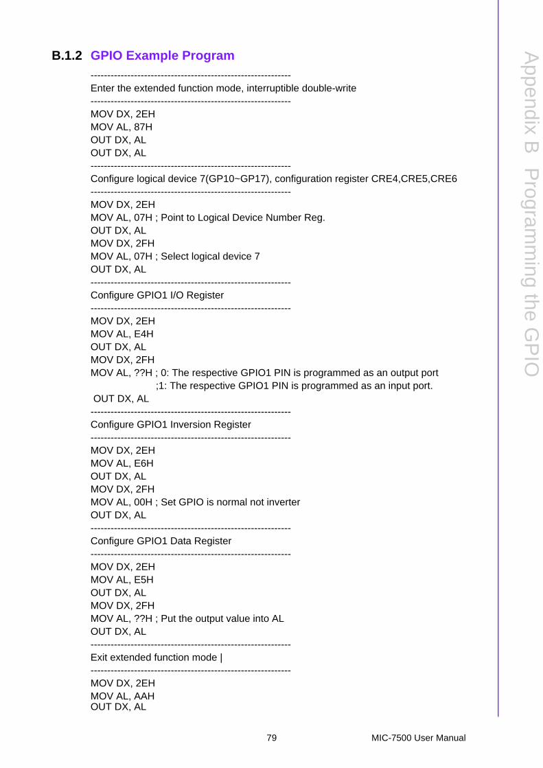
B.1.2 GPIO Example Program
------------------------------------------------------------Enter the extended function mode, interruptible double-write------------------------------------------------------------MOV DX, 2EHMOV AL, 87HOUT DX, ALOUT DX, AL------------------------------------------------------------Configure logical device 7(GP10~GP17), configuration register CRE4,CRE5,CRE6------------------------------------------------------------MOV DX, 2EHMOV AL, 07H ; Point to Logical Device Number Reg.OUT DX, ALMOV DX, 2FHMOV AL, 07H ; Select logical device 7OUT DX, AL------------------------------------------------------------Configure GPIO1 I/O Register------------------------------------------------------------MOV DX, 2EHMOV AL, E4HOUT DX, ALMOV DX, 2FHMOV AL, ??H ; 0: The respective GPIO1 PIN is programmed as an output port
;1: The respective GPIO1 PIN is programmed as an input port. OUT DX, AL
------------------------------------------------------------Configure GPIO1 Inversion Register------------------------------------------------------------MOV DX, 2EHMOV AL, E6HOUT DX, ALMOV DX, 2FHMOV AL, 00H ; Set GPIO is normal not inverterOUT DX, AL------------------------------------------------------------Configure GPIO1 Data Register------------------------------------------------------------MOV DX, 2EHMOV AL, E5HOUT DX, ALMOV DX, 2FHMOV AL, ??H ; Put the output value into ALOUT DX, AL------------------------------------------------------------Exit extended function mode |------------------------------------------------------------MOV DX, 2EHMOV AL, AAHOUT DX, AL
79 MIC-7500 User Manual

www.advantech.comPlease verify specifications before quoting. This guide is intended for referencepurposes only.All product specifications are subject to change without notice.No part of this publication may be reproduced in any form or by any means,electronic, photocopying, recording or otherwise, without prior written permis-sion of the publisher.All brand and product names are trademarks or registered trademarks of theirrespective companies.© Advantech Co., Ltd. 2016