user manual gaia-wind 11 kw turbine - segencatalogue.segen.co.uk/reseller/docs/gw-uk-18-0808 user...
TRANSCRIPT
USER MANUAL Gaia-Wind 11 kW Turbine

2
Copyright © 2008 Gaia-Wind Ltd. 1 Ainslie Road Hillington Park
Glasgow G52 4RU United Kingdom
Tel: +44 (0) 845 871 4242
Document Reference number: GW-UK-18-0808 User Manual
Document revised: August 2008
All illustrations and photographs Copyright © Gaia-Wind Ltd.. No part of this manual may be transmitted into any form by any means wihtout permission from Gaia-Wind Ltd. The information given in this user manual is believed to be accurate and reliable at time of printing. However, Gaia-Wind Ltd. Accepts no liability for the details contained herein. All specifications are subject to change without prior notice
Your own
Wind Turbine
3
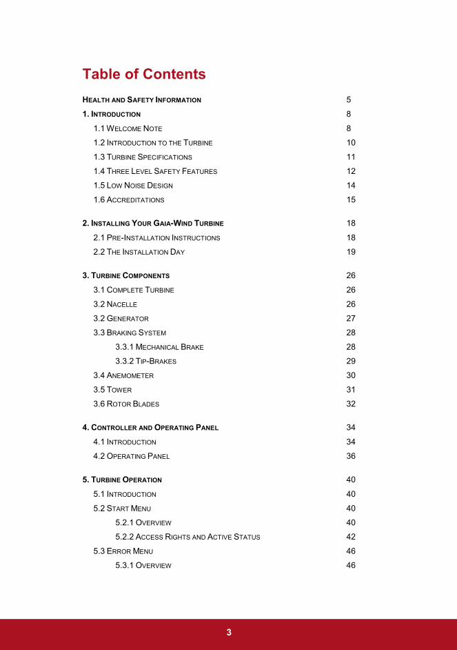
Table of Contents
HEALTH AND SAFETY INFORMATION 5
1. INTRODUCTION 8
1.1 WELCOME NOTE 8
1.2 INTRODUCTION TO THE TURBINE 10
1.3 TURBINE SPECIFICATIONS 11
1.4 THREE LEVEL SAFETY FEATURES 12
1.5 LOW NOISE DESIGN 14
1.6 ACCREDITATIONS 15
2. INSTALLING YOUR GAIA-WIND TURBINE 18
2.1 PRE-INSTALLATION INSTRUCTIONS 18
2.2 THE INSTALLATION DAY 19
3. TURBINE COMPONENTS 26
3.1 COMPLETE TURBINE 26
3.2 NACELLE 26
3.2 GENERATOR 27
3.3 BRAKING SYSTEM 28
3.3.1 MECHANICAL BRAKE 28
3.3.2 TIP-BRAKES 29
3.4 ANEMOMETER 30
3.5 TOWER 31
3.6 ROTOR BLADES 32
4. CONTROLLER AND OPERATING PANEL 34
4.1 INTRODUCTION 34
4.2 OPERATING PANEL 36
5. TURBINE OPERATION 40
5.1 INTRODUCTION 40
5.2 START MENU 40
5.2.1 OVERVIEW 40
5.2.2 ACCESS RIGHTS AND ACTIVE STATUS 42
5.3 ERROR MENU 46
5.3.1 OVERVIEW 46

4
5.3.2 ACCESSING THE ERROR MENU 47
5.3.3 ERROR TYPES 48
5.3.4 RESETTING OF ERRORS 50
5.4 STATUS MENU 52
5.4.1 OVERVIEW 52
5.4.2 SYSTEM SUBMENUS 54
5.4.3 SYSTEM PRODUCTION 55
5.4.4 WIND SUBMENU 57
5.4.5 RPM SUBMENU 57
6. OPERATING PROCEDURES 60
6.1 AUTO-START 60
6.2 AUTOMATIC SHUTDOWN 60
6.2.1 MAX WIND 60
6.2.2 ROTOR OVER-SPEED 61
6.2.3 GENERATOR OVER-SPEED 61
6.2.4 MINIMUM POWER 62
6.2.5 VIBRATIONS 62
6.2.5 CABLE TWIST 62
6.3 MANUAL AND EMERGENCY STOP 63
6.4 BRAKING PROCEDURE 64
7. SERVICING AND MAINTENANCE 68
7.1 USER MAINTENANCE 68
7.1.1 RESETTING ERRORS 68
7.1.2 VISUAL INSPECTIONS 68
7.2 SERVICING INTERVALS 69
7.2.1 THREE MONTH SERVICE 69
7.2.1 ANNUAL SERVICE 69
7.3 REPLACEMENT PARTS 70
8. FREQUENTLY ASKED QUESTIONS 71
INDEX 73
ANNEX 1 – GLOSSARY OF TERMS 75
ANNEX 2 – TECHNICAL DATA 78
ANNEX 3 – ERROR MESSAGES 80
5
Health and Safety Information
Gaia-Wind Ltd. strongly recommends that all servicing & maintenance
procedures other than cursory visual inspection be carried out by
adequately trained and experienced personnel. Personnel deemed to
be adequately qualified will;
• Be specifically trained to work at heights, ideally with a “BWEA
Working at Height Certificate” or equivalent, using peak-less
climbing helmet, safety harness with double lanyards and shock
absorber, work positioning device, tower rescue kit, high visibility
vest and steel toe cap boots.
• Have experienced working on the Gaia-Wind 11kW Turbine
• Ensure that only one person is permitted inside of the working
basket at any one time
• Ensure that a proper and comprehensive risk assessment has been
carried out prior to starting any work
Ensure that these instructions are read
thoroughly and understood. It is essential that
they are retained, along with the remainder of the
manual, as they contain important safety
information that must be adhered to.
6
Further advice to the turbine owner;
• Alterations to the control parameters can only be made by Gaia-
Wind or a Gaia-Wind accredited servicing company
• In the event of abnormal noise or unusual operation being observed
turn-off the turbine and contact Gaia-Wind or a Gaia-Wind
accredited servicing company
• Shut off the turbine should ice accumulate on the blades
• Do not paint the blades or the turbine as this will degrade the
coating on the blade surface
• If in doubt on any procedural issues contact Gaia-Wind or a Gaia-
Wind accredited servicing company

7
Introduction

8
1. Introduction
1.1 Welcome Note
Thank you for choosing to purchase a Gaia-Wind 11 kW Wind Turbine!
Gaia-Wind are delighted that you have decided to install our small-wind
turbine. We believe that with ‘Your Own Wind Turbine’ you will very
quickly notice the benefits gained by your home or business. The
turbine allows you to substantially reduce your annual energy bills and
take sizeable steps towards lowering your carbon-footprint and
achieving energy sustainability.
This document has been written specifically with the turbine user in
mind. It is therefore strongly recommended that you read this manual
carefully, and ensure that it is retained for future reference.
The manual provides a comprehensive overview of the turbine
operating procedures and the control system. This will allow you to
monitor the turbine whilst it is in operation and determine how much
electricity you are generating, and thus how much money you are
saving. In addition you can determine the equivalent carbon dioxide
savings that you will achieve.
Please take careful note of the health and safety information
summarised on the opening page. If you have any additional concerns
on the health and safety aspects of the turbine, please contact Gaia-
Wind.

9
We would like to congratulate you once again on your purchase, and
hope that you enjoy generating your own energy, with ‘Your Own Wind
Turbine’.
Regards,
Gaia –Wind
Independent Energy – Environmentally Friendly Energy

10
1.2 Introduction to the Turbine
The Gaia-Wind turbine is in the ‘small wind turbine category’ and has a
peak rated output of 11kW. It produces an energy yield that is practical
for supplying electricity to premises such as private houses, farms,
offices, small businesses and public buildings where the primary goal is
to reduce the amount of electricity imported rather than generate
specifically for export to the grid.
The turbine has been developed according to ‘Danish design’; the
design basis for most of the large commercial turbines used today. Like
its bigger relatives, it has a slow rotation speed which is independent of
the wind speed. It also incorporates many of the control and safety
features from the large turbines.
The Gaia-Wind turbine is configured to give an optimal yield in
moderate wind speed sites i.e. those with an ‘annual average wind
speed’ in the range of 4.5-7.5 m/s. As such it complements the wind
conditions found in many rural areas of mainland Britain.
Components used in a Gaia-Wind turbine have been carefully selected
for their quality, reliability and low maintenance.
The outstanding electricity production in moderate wind speeds,
typically 30.000 kWh per year, is due to the large rotor. With a 13 metre
rotor diameter the Gaia-Wind 11 kW sweeps an area of 133 square
metres which is more than double that of most competing machines.

11
1.3 Turbine Specifications
The power output of a wind turbine varies with the wind speed. This is
represented by a turbine power curve. Figure 1.1 below represents the
power curve for the 50Hz version of the Gaia-Wind 11kW turbine. This
curve provides a good indication of what the electrical power output of
the turbine will be over a range of wind speeds.
With its large rotor diameter, an attribute of the Gaia-Wind turbine is
high performance in moderate wind speeds.
The key-points of the power curve are outlined in the table below;
Cut-In Speed
3.5 m/s
The minimum wind speed at which the
turbine will deliver useful power.
0
2
4
6
8
10
12
14
0 2 4 6 8 10 12 14 16 18 20 22 24 26
Pow
er (k
W)
Wind Speed (m/s)
Cut-In Speed Cut-Out Speed Rated Speed

12
Rated Speed
9.5 m/s
The wind speed at which the rated power,
11kW, is reached.
Cut-Out Speed
25.0 m/s
The maximum wind speed at which the
turbine is permitted to deliver power. The
operating range of a turbine is limited due
to engineering design and safety
constraints. The cut-out speed for the
turbine is 25 m/s, although wind speeds
this high are rare.
Turbine Specifications
See Annex 2, “Technical Data”
1.4 Three Level Safety Features
Safety features are a vitally important aspect of any turbine design. The
Gaia-Wind turbine has a number of safety features that ensure that
rotor speed and power generation are kept under control. There are
three distinct levels of protection;
Base Level Passive
The design of the blades introduces a gradual
stalling effect as wind speeds rise above 9
m/s, which limit power output from the turbine.

13
Secondary Level Controller Initiated (Active)
At wind speeds above 25 m/s the turbine
controller automatically activates the
mechanical brake. This stops the turbine
running. The brake is automatically released
when the wind speed drops below an average
of 18 m/s over a period of 10 minutes.
The mechanical brake is also activated in
case of a fault in the electrical grid, excessive
vibrations, or over speeding of the rotor or
generator.
Tertiary Level Passive
In the extremely unlikely event that neither the
base nor secondary level safety mechanisms
stop the turbine, centripetally activated
aerodynamic brakes, concealed in the rotor
tip, are released. The effect of this is to spoil
the aerodynamic lift of the rotor and hence
stop it rotating.
In addition there exists an emergency stop function on the turbine
controller. At any time the user can override of the turbine control
system and stop the turbine. More details can be found in section 6 of
this manual.

14
1.5 Low Noise Design
As with all rotating machinery, noise will be produced, and minimising
this effect is a key objective for Gaia-Wind’s engineers.
The principal source of noise originates from the turbine blades, and
this ‘aerodynamic noise’ increases exponentially with the rotational
speed of the blades. The constant and low rotational speed of the
Gaia-Wind turbine makes it among the quietest in its class. In practice
the turbine noise is often masked by background noises such as wind or
traffic.
The table below provides indicative noise levels at various distances
from the base of the turbine. The data is derived from independent
measurements on several Gaia-Wind turbines.
Noise Level dB (A) Comparator
At 30 m 50 Conversational Speech Car at 100 m Driving at 40 mph
At 60 m 45 Living Room
Over 100 m < 40 Rural Night-Time Background

15
1.6 Accreditations
The Gaia-Wind 11 kW turbine has received the UK Clear Skies
accreditation, accreditation number WT5038. This denotes that the
turbine is eligible for all grant schemes for small wind turbines.
The Gaia-Wind 11 kW turbine has been approved under the official
HB-standards of the Danish Government. Gaia-Wind is the only
manufacturer of small wind turbines ever to achieve this approval.

16

17
Installing your Gaia-Wind Turbine

18
2. Installing Your Gaia-Wind Turbine
2.1 Pre-Installation Instructions
Suitable locations for your turbine will have been discussed with a Gaia-
Wind representative prior to installation. The final location will take into
account the local topography and proximity to obstacles, such as trees,
roads and nearby buildings.
Prior to the installation of your turbine it is necessary to obtain planning
consent from the relevant authorities.
Customers can apply for planning directly or use a consultant to apply
on their behalf. In each case Gaia-Wind will provide support.
If any, planning restrictions are most commonly imposed on the basis
of anticipated noise emission and visual impact on the landscape.
At the time of signing the contract with Gaia-Wind you will be provided
with a list of requirements. Requirements will depend on your degree of
direct involvement with the project but for example could include;
digging the foundation hole, contracting a foundation builder, digging a
cable trench, providing a three-phase grid-connection with import/export
meter, achieving planning consent and ensuring suitable access for a
crane and for the delivery lorry. You must fulfil these obligations prior to
the agreed installation day. This will be covered in the contract.

19
2.2 The Installation Day
The installation of a Gaia-Wind Turbine must be done either by Gaia-
Wind or through a Gaia-Wind accredited installer. Please contact Gaia-
Wind if you want to check/verify whether your contact person is an
accredited Gaia-Wind installer. The installation of the turbine should
normally take only one day. The Installation Team will consist of two
engineers, a crane driver and an electrician depending on
circumstances. One of the engineers will be introduced as Installation
Manager and this person will be in charge of everything that takes place
that day. All people on site should follow swiftly the instructions given by
this person. All questions and remarks should be directed to the
Installation Manager.
There are 4 main components to the installation of the turbine;
1. Foundation preparation
2. Electrical installation
3. Mechanical installation
4. Commissioning
It may be more economic for the customer to arrange a contract for
foundation works independently. However there are strict requirements
and guidelines relating to the foundations that must be considered
during construction. The foundation specifications must be obtained
from Gaia Wind and followed strictly.
It should be noted that installation is
dependent on suitable weather, ground, and
wind conditions.

20
Step 1 – Foundations
The Gaia-Wind turbine foundation
has a footprint of approximately 5
meters square. The foundation is
composed of multiple layers of
steel reinforcement mesh bound
together with braces to form a
steel frame that will form the base
of the tower. The metalwork is
placed inside the excavated hole
and levelled, before being filled
with concrete.
Foundation preparations are
required to be completed a
minimum of 10 days in advance
of the installation date. This is to
ensure adequate curing of the
concrete. Also the controller
stand will be cast in the concrete
during the foundation work. On
the installation day the controller
will be mounted on this stand.
Gaia-Wind maintain the right to refuse
installation of the turbine on the grounds of
safety if it has been determined that the
foundation or electrical preparation work is
unsatisfactory, or when proper and safe
site access has not been provided

21
Step 2 – Delivery and Unloading
The Gaia-Wind turbine is delivered
on a single lorry. The delivery will
consist of
• Multi part tower; both lattice
and tubular towers arrive in
several sections to be
assembled in-situ
• Ladder and Working Basket
• Turbine blade and hub
• Pre-assembled and tested
nacelle
• Pallet of loose items; fasteners
and fittings
• Controller
All the above items are carefully
offloaded from the truck with a
crane by the Installation Team.

22
Step 3 – Assembly
The tower sections are assembled.
The nacelle is mounted onto the
top section of the tower
Ladder sections and working
basket are fixed onto the tower
The rotor assembly is mounted
onto the main shaft.
Step 4 – Raising the Turbine
The turbine is raised by the crane.
Once vertical the tower is securely
fixed to the foundation steelwork.
The tower will be carefully levelled
to ensure it is in an exactly vertical
position.

23
Step 5 – Commissioning & Starting the Turbine
Once fully erected and fastened
to the foundation, the turbine
commissioning procedure takes
place. Upon completion of all
commissioning checks the turbine
can be started and your turbine
will begin to generate your own
electricity.
Your own
Wind Turbine

24

25
Turbine Components

26
3. Turbine Components
3.1 Turbine
The diagram below shows the Gaia-Wind 11kW Turbine, indicating the
location of the principal components. Please note that although the
diagram shows a lattice tower, the drawing is also consistent for the
tubular tower.
3.2 Nacelle
The nacelle of the turbine refers to the housing that contains all of the
drive train and machinery necessary for the conversion of the incoming
wind to electrical energy. The principle components included within the
Figure 3.1: Main Components
1. Blade Tip
2. Rotor Blade
3. Nacelle
4. Anemometer
5. Working Basket
6. Hub Fork
7. Cable Guide
8. Tower (Lattice)
9. Ladder
10. Cable Twist Sensor
11. Controller
12. Foundation
27
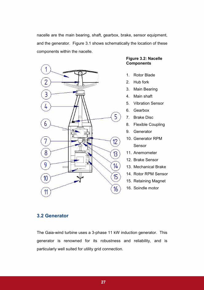
nacelle are the main bearing, shaft, gearbox, brake, sensor equipment,
and the generator. Figure 3.1 shows schematically the location of these
components within the nacelle.
3.2 Generator
The Gaia-wind turbine uses a 3-phase 11 kW induction generator. This
generator is renowned for its robustness and reliability, and is
particularly well suited for utility grid connection.
Figure 3.2: Nacelle Components
1. Rotor Blade
2. Hub fork
3. Main Bearing
4. Main shaft
5. Vibration Sensor
6. Gearbox
7. Brake Disc
8. Flexible Coupling
9. Generator
10. Generator RPM
Sensor
11. Anemometer
12. Brake Sensor
13. Mechanical Brake
14. Rotor RPM Sensor
15. Retaining Magnet
16. Spindle motor
28
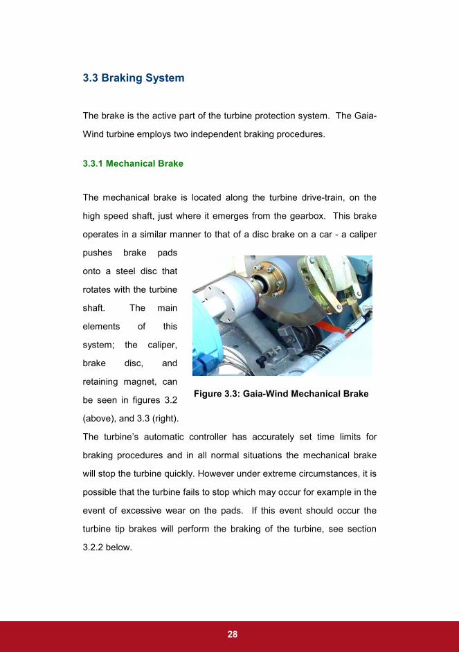
Figure 3.3: Gaia-Wind Mechanical Brake
3.3 Braking System
The brake is the active part of the turbine protection system. The Gaia-
Wind turbine employs two independent braking procedures.
3.3.1 Mechanical Brake
The mechanical brake is located along the turbine drive-train, on the
high speed shaft, just where it emerges from the gearbox. This brake
operates in a similar manner to that of a disc brake on a car - a caliper
pushes brake pads
onto a steel disc that
rotates with the turbine
shaft. The main
elements of this
system; the caliper,
brake disc, and
retaining magnet, can
be seen in figures 3.2
(above), and 3.3 (right).
The turbine’s automatic controller has accurately set time limits for
braking procedures and in all normal situations the mechanical brake
will stop the turbine quickly. However under extreme circumstances, it is
possible that the turbine fails to stop which may occur for example in the
event of excessive wear on the pads. If this event should occur the
turbine tip brakes will perform the braking of the turbine, see section
3.2.2 below.
29
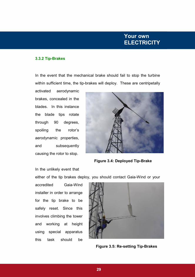
3.3.2 Tip-Brakes
In the event that the mechanical brake should fail to stop the turbine
within sufficient time, the tip-brakes will deploy. These are centripetally
activated aerodynamic
brakes, concealed in the
blades. In this instance
the blade tips rotate
through 90 degrees,
spoiling the rotor’s
aerodynamic properties,
and subsequently
causing the rotor to stop.
In the unlikely event that
either of the tip brakes deploy, you should contact Gaia-Wind or your
accredited Gaia-Wind
installer in order to arrange
for the tip brake to be
safely reset. Since this
involves climbing the tower
and working at height
using special apparatus
this task should be
Your own
ELECTRICITY
Figure 3.4: Deployed Tip-Brake
Figure 3.5: Re-setting Tip-Brakes

30
Figure 3.6: Anemometer
undertaken only by personnel with the appropriate training and safety
equipment.
Contact Gaia-Wind or your accredited Gaia-
Wind installer in order to arrange for the tip
brake to be safely reset. DO NOT attempt to
perform this task yourself as it requires
specialist training and apparatus.
3.4 Anemometer
An anemometer is located
on the upwind side of the
nacelle. The purpose of this
device is to measure the
wind speed at the turbine
hub-height. The wind speed
measurements recorded by
the anemometer are used by
the controller to monitor and
control the turbine, mainly during start-up and shot down.

31
3.5 Tower
There are two tower types available for the Gaia-Wind 11 kW Turbine -
traditional lattice and tubular.
The traditional lattice tower is composed of welded galvanised steel
profiles and is mounted on 4 legs that are embedded in the concrete
foundation. The principal advantage of this design is less material, and
hence reduced cost.
The tower can also be supplied as a tubular structure. This tower is
conically shaped, increasing in diameter towards the base. This
increases structural integrity and makes an elegant presentation.
Figure 3.7: Turbine Towers, Lattice (Left)
and Tubular (Right)

32
Aside from the issue of cost, the other main difference between the two
tower types is aesthetics. Both the tubular and lattice tower are
designed to cause minimal visual intrusion on the landscape. The sleek
tubular tower compliments modern structures, and when viewed at a
distance, the open structure of the lattice tower causes the outline to
fade.
3.6 Rotor Blades
The rotor blades are constructed of the composite material GRP (Glass
Reinforced Polyester) commonly referred to as fibreglass. There are
many advantages for the use of GRP for this purpose, principally a
good strength to weight ratio and resistance to degradation from
environmental factors.

33
Operating Panel
Controller and Operating Panel

34
Figure 4.1: Controller Cabinet
4. Controller and Operating Panel
4.1 Introduction
This section gives a brief overview of the Gaia-Wind 11 kW Wind
turbine controller and operating panel. The controller is essential for
ensuring the efficient and safe operation of the turbine. All procedures
are controlled automatically based upon signals from various sensors
throughout the turbine. User intervention is only required when errors
have occurred.
To open the controller cabinet
use the supplied key; inserting
into the 2 keyholes at the top and
bottom of the left hand side of the
cabinet door. Push in firmly and
turn clock-wise to release the
latch on each. The door should
then easily swing open.
• DO NOT open the control cabinet door in wet conditions
• There are no user serviceable parts inside the cabinet
• Customers should only touch operating panel keypad (see
Section 4.2)
• DO NOT place any metal objects in or near cabinet
• If you see any sign of water in the cabinet, isolate the
controller and do not operate. Contact Gaia-Wind or your
accredited Gaia-Wind installer.

35
All of the turbine’s necessary electrical switchgear, fuses, contactors
and connectors are housed in a weatherproof unit located at the foot of
the tower. The interior of the controller cabinet can be seen in figure
4.1.
The controller also allows for the monitoring of the turbine performance.
Instantaneous and time averaged readings relating to energy
production, wind speed, and power output can be accessed through the
operating panel. Daily energy production is archived by the controller
for one month back. The total monthly production is stored for a period
of 12 months, and total yearly production is archived for 20 years
Figure 4.1: Turbine Controller Cabinet
Operating Panel
keypad Computer
Capacitor Bank
Soft Starter
Current and Voltage
Measurement
Contactors & Automatic
Fuses

36
The controller will produce an error message should a fault be detected
in the normal running of the turbine. Details of the error will appear on
the operating panel. The most common errors and the recommended
actions are detailed in section 5.
4.2 Operating Panel
The IC-1000 operating panel
includes a screen and keypad.
The keys are activated by pressing
down on the relevant symbol. A
successful Keypad entry is
signalled by the illumination of the
LED labelled ‘Key’, accompanied
by an electronic beep. Figure 4.2
displays the operating panel.
The operating panel has 8 main menus corresponding to different
aspects of turbine control. Submenus exist within each of these menus.
Navigation between all menus is achieved using the keypad.
The information below details the primary operating panel entry
functions.
Figure 4.2: The Gaia-Wind
Operating Panel

37
Keypad Function
Stop the turbine
Release the brake and start the turbine
Move cursor line up
Navigate to next menu
Navigate to previous menu
Move cursor line down
Reset, erase error status
Shift to last menu line
Leave a submenu

38
Leave all submenus
Enter

39
Turbine Operation

40
5. Turbine Operation
5.1 Introduction
This section will explain how to navigate the menus of the operating
panel and monitor the data relating to the performance of the turbine.
This is achieved using the operating panel functions outlined in section
4.2.
5.2 Start Menu
5.2.1 Overview
The most convenient menu is the start menu. This menu shows real
time and time-averaged information and displays the current status of
the turbine. The status will show whether there is an error with the
turbine, or whether it is running free of errors, see Figure 5.1 (below).
Note that the backlight of the screen illuminates when any key is
pressed making the screen easier to read, especially in low light or at
night. The backlight will switch off when the keypad has not been
pressed for a short period.
The Start Menu (Section 5.2) is the only menu
which can be viewed without gaining access.
Accessing any other menu requires “Access
Rights”, see Section 5.2.2

41
Figure 5.1: Start Menu – Running (Left), Braked (Right)
First Line
B The brake is engaged
G1 Indicates that the generator is ‘cut-in’ (connected to the grid.
249 V Grid voltage (average per phase)
11.5 kW Average power output over 30 seconds
Second Line
9.5 m/s Average wind speed over 30 seconds
57/1021 rpm Rotor/Generator speeds
Third Line
The third line indicates the most recent event registered by the turbine.
In the example above this is the cut-in of the generator (left) and
stopping of the turbine (right)

42
Fourth Line
This shows the status of the turbine. The display in figure 5.1 (left)
indicates that the system is OK, i.e. there are no errors in the turbine.
Alternative status messages that may appear in this line include,
“Error”, and “Warning”, see figure 5.1 (right). Further information
regarding errors is included in section 5.3 of this document.
Fifth & Sixth Lines
The fifth and sixth lines indicate the level of access rights and active
status request. Access rights and active status must be attained in
order to use the operating panel. Normal Users will have access level
50.
If access rights and active status are not obtained, only the start menu
will be visible and navigation to other menus prohibited. See the
section 5.2.1 on access rights and active status for further details.
5.2.2 Access Rights and Active Status
The Start Menu displays the lines, ‘Access Rights’, and ‘Request Active
Status’. Permission to use the operating panel can only be acquired if
the access rights and active status are obtained. The following steps
should be followed in order to attain access rights and active status.
43
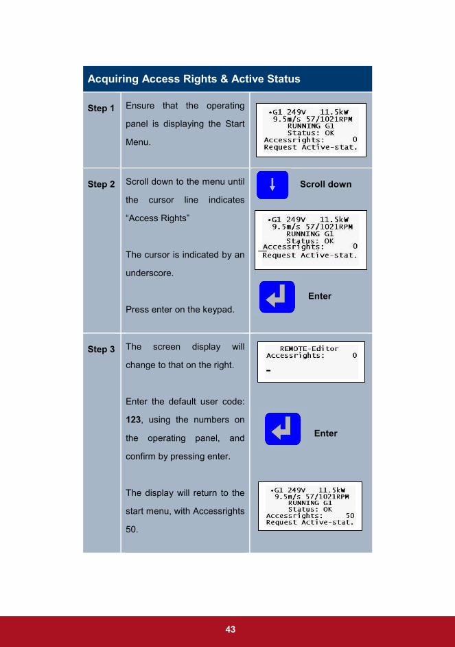
Acquiring Access Rights & Active Status
Step 1 Ensure that the operating
panel is displaying the Start
Menu.
Step 2 Scroll down to the menu until
the cursor line indicates
“Access Rights”
The cursor is indicated by an
underscore.
Press enter on the keypad.
Scroll down
Enter
Step 3 The screen display will
change to that on the right.
Enter the default user code:
123, using the numbers on
the operating panel, and
confirm by pressing enter.
The display will return to the
start menu, with Accessrights
50.
Enter

44
Step 4 Navigate the start menu
down until the cursor
indicates, “Request active-
stat”
Press enter on the keypad
Scroll down Enter
Step 5 Enter the user ID: 1 and
Confirm by pressing enter on
the keypad
The screen will revert back to
the start menu with both
access rights and active
status.
Enter
Step 6 Ensure that the LED labelled
‘Active’ on the top right hand
side of the keypad is
illuminated. This confirms
that active status has been
granted.
It is important that prior to leaving the turbine,
that the access rights and active status are
disabled. Therefore the following procedure
should be followed upon completion of using the
controller.

45
Releasing Active Status & Access Rights
Step 1 Ensure that the operating
panel display shows the Start
Menu.
Step 2 Navigate the start menu
down until the cursor
indicates, “Release active-
stat”
Press enter on the keypad
The display remains on the
start menu, with active status
released
Enter
Step 3 Navigate the start menu to
the line “Access Rights”.
Press enter on the keypad
two times.
Enter
Step 4
The display will revert to the
original start menu. You are
now logged out of the
turbine.

46
5.3 Error menu
5.3.1 Overview
The turbine is equipped with
numerous sensors. These sensors
continuously monitor the turbine
and the information they record is
used by the controller.
When the sensors detect an error, the controller will automatically stop
the turbine. Confirmation of the error is indicated on the start menu
under status, see figure 5.2. By accessing the error menu the source of
the error can be obtained, see section 5.3.2.
The error menu on the operating
panel contains the following
menu lines,
First Line
Error Result: Press enter on this line to access the Error Results
Menu
Figure 5.2: Start Menu
Indicating Errors
Figure 5.3: Error Menu

47
Second Line
This line gives all active status codes
Third Line
Displays the most recently activated error. N.B. the error in figure 5.3
indicates that the turbine has been manually stopped. This is one
example of an error message. An overview of errors is detailed in
Annex 3.
5.3.2 Accessing the Error Menu
Accessing the Error Menu
Step 1
Ensure that the Start Menu is
displayed on the operating
panel.
If you have not done so,
obtain Access Rights and
Active Status before
continuing. See section
5.2.1 for details
Step 2
Scroll down the menu line
until the cursor is on the
Scroll down

48
fourth line “Status: Error”.
Press enter on the operating
panel.
Enter
Step 3
The error menu is displayed
on the operating panel
screen. It shows all active
status codes.
Step 4 Scroll onto the error and press enter to gain more
information on the error. This will detail the date and time
at which the error occurred.
Step 5 Revert back to the start
menu by pressing escape.
Escape
5.3.3 Error Types
A Status Code is an error code which becomes active when a particular
error occurs or if the controller detects that a certain parameter has
been exceeded. For example, if the grid voltage is too high, if there is a
loss of mains supply or if the rotor or generator speeds are excessive.
For each status code a set of parameters determines the consequences
of the code activation/ error which can include stopping the turbine, re-

49
setting the error after a delay etc. Each status code will be dealt with
depending on its assigned re-set level.
To obtain information about a given status code, place the cursor
at the code and press ENTER.
There are three error re-set levels; Auto, Manual and Remote, classified as follows;
Auto (A)
The active status code is automatically reset by the controller of the
turbine when the conditions for resetting are present, in other words
when the original reason for its activation has stabilised and is no
longer present. Alternatively, the status code may be reset manually
or by remote control by users with a password level higher than that
indicated in the status code.
Manual (M)
The active status code can be reset by the user via the operating
panel by users with a password level equal to or higher than the
one indicated in the status code.
Remote (R)
The status code may be reset manually or by remote control only by
users with a password level higher than that indicated in the status
code

50
The table in Annex 3 gives a full list of potential error messages. Each
error is accompanied by a short description and indentified as Auto,
Manual or Remote reset and also given a re-set delay and required
password level to be able to re-set. Instructions on how to manually
reset errors are detailed in section 5.3.4 below.
5.3.4 Resetting of Errors
The turbine will only operate when no error signals are detected.
Therefore errors must be reset to resume turbine operation. The
method for resetting errors is dependent on the type of error. The
following procedure should be followed to reset manual errors.
Resetting Error Menu
Step 1 Ensure that the Start Menu is
displayed on the operating
panel.
If you have not done so,
obtain Access Rights and
Active Status. See section
5.2.1 for details
Although it is possible to manually reset
many of the errors in Annex 3, please read
and adhere to the instuctions for each error.
This is essential for ensuring the continued
performance of your turbine.
51
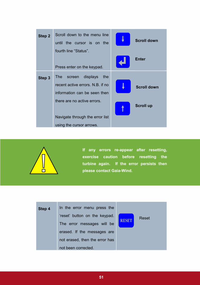
Step 2 Scroll down to the menu line
until the cursor is on the
fourth line “Status”.
Press enter on the keypad.
Scroll down
Enter
Step 3 The screen displays the
recent active errors. N.B. if no
information can be seen then
there are no active errors.
Navigate through the error list
using the cursor arrows.
Scroll down Scroll up
Step 4 In the error menu press the
‘reset’ button on the keypad.
The error messages will be
erased. If the messages are
not erased, then the error has
not been corrected.
Reset
If any errors re-appear after resetting,
exercise caution before resetting the
turbine again. If the error persists then
please contact Gaia-Wind.

52
Step 5 Press the escape button to
return to the main menu.
Escape
Step 6 The turbine will start
automatically within 60
seconds subject to sufficient
wind.
Alternatively, the turbine can
be started immediately by
pressing the start button.
Start
Step 7 Release access rights and
active status if finished
operating the turbine.
See section 5.2.1
5.4 Status Menu
5.4.1 Overview
The status menu provides a useful
tool for viewing data relating to a
range of performance characteristics,
such as production data. The data
can be reviewed over a range of
time-frames, including daily, monthly,
and yearly.
Figure 5.4: Status Menu
53
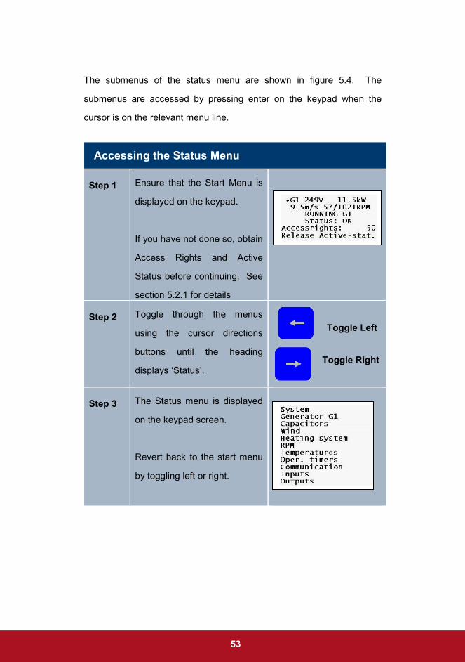
The submenus of the status menu are shown in figure 5.4. The
submenus are accessed by pressing enter on the keypad when the
cursor is on the relevant menu line.
Accessing the Status Menu
Step 1 Ensure that the Start Menu is
displayed on the keypad.
If you have not done so, obtain
Access Rights and Active
Status before continuing. See
section 5.2.1 for details
Step 2
Toggle through the menus
using the cursor directions
buttons until the heading
displays ‘Status’.
Toggle Left
Toggle Right
Step 3
The Status menu is displayed
on the keypad screen.
Revert back to the start menu
by toggling left or right.

54
5.4.2 System Submenus
To access the system
submenu press enter on
the first line of the Status
menu “System”. The result
will generate the display
shown in figure 5.5 (left).
The information below
describes the data contained in each of the menu lines.
System Submenu Lines
Production and Consumption
Production of the turbine. The total
kilowatt hours produced by the turbine
will be counted and recorded. Pressing
enter once again on this line enables
data to be viewed from the previous
month, 12 months, and 20 years.
Operation timer / counter Counts the number of hours of
production from the turbine.
Stop timer / counter Counts the hours and times the turbine
has been stopped.
Figure 5.5: System Submenu

55
Brake timer / counter Counts the hours and times that the
turbine brake has been activated.
IC-1000 OK timer / counter
Counts the hours and times that the IC-
1000 control unit has been switched on.
Grid OK timer / counter This counts the hours and times that the
grid has been OK
5.4.3 System Production
Accessing System Production
Step 1
Ensure that the Status Menu is
displayed on the keypad
screen, see section 4.4.1.
Press enter on the Menu Line
‘System’.
The system submenu will
appear on the screen.
Enter

56
Step 2
Navigate to the submenu line,
‘prod./consump.’, and press
enter.
Scroll Down
Enter
Step 3
The display should give a
selection of time frames over
which to view data.
Scroll to the desired time
frame and press enter.
Step 4 The final screen shows the
production data. The
important information here is
the top line, the energy
produced by the turbine.
Step 5
To return to the previous menu
press escape.
To return to the Status menu,
hold control and escape.
Return to Submenu
Return to Status Menu
57
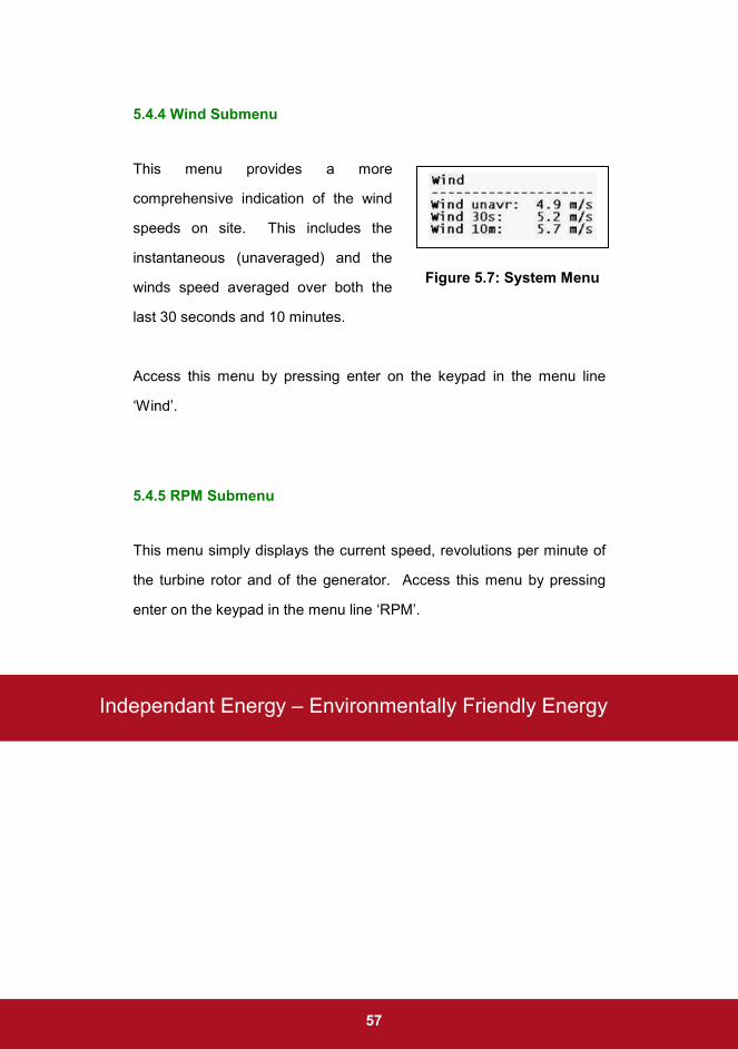
5.4.4 Wind Submenu
This menu provides a more
comprehensive indication of the wind
speeds on site. This includes the
instantaneous (unaveraged) and the
winds speed averaged over both the
last 30 seconds and 10 minutes.
Access this menu by pressing enter on the keypad in the menu line
‘Wind’.
5.4.5 RPM Submenu
This menu simply displays the current speed, revolutions per minute of
the turbine rotor and of the generator. Access this menu by pressing
enter on the keypad in the menu line ‘RPM’.
Figure 5.7: System Menu
Independant Energy – Environmentally Friendly Energy

58

59
Operating Procedures

60
6. Operating Procedures
6.1 Auto-Start
Auto-start refers to the process by which the turbine starts automatically
when the control measures a pre-defined wind speed of at least 3.5
metres per second for 30 seconds. This is the ‘cut-in’ speed, and is the
point at which the turbine will start to generate electricity. Through a
‘soft-starter’ the controller uses the generator as a motor to bring the
rotor up to the operating speed.
Auto-start enables maximum exploitation of lower wind speeds and
hence greatest electrical energy production.
6.2 Automatic Shutdown
6.2.1 Max Wind
The turbine will shutdown automatically when the wind speed registered
by the anemometer is too high. This is important to protect components
such as the generator and gearbox.
The controller automatically shuts-down the turbine in the following
conditions;
• An average wind speed over a period of 10 minutes is 20
m/s or over
• The wind speed exceeds 25 m/s

61
6.2.2 Rotor Over-Speed
Rotor over-speed is when the rotor speed is greater than the rated
speed. For the Gaia-Wind turbine the rated rotor speed is nominally 56
rpm but can vary between 55 and 57rpm.
Following shutdown due to rotor overspeed the tip brakes may need to
be reset. You should contact Gaia-Wind or a Gaia-Wind accredited
servicing company.
Generator overspeed is when the generator rpm sensor detects speed
greater than 1116 rpm.
6.2.3 Generator Over-Charge
The turbine brake is activated if the recorded power output of the
generator is large. This is referred to as ‘over-charge’ and is necessary
to protect the generator from damage. The conditions are;
There are two defining conditions of rotor over-speed;
• At 10% above the rated rotor speed (62 RPM) the
mechanical brake is activated
• At 15% above the rated rotor speed (65 RPM) the
aerodynamic tip-brakes are activated
• An average power output of 15 kW averaged over a 10
minute period
• The generator power exceeds 18 kW

62
6.2.4 Minimum Power
If the turbine power output is less than 0.1kW over a period of one
minute the generator will ‘cut-out’, i.e. it will stop producing. Under
these circumstances the rotor will continue to rotate without producing
electrical energy, ‘freewheeling’. This will continue until favourable
conditions for generation are regained.
6.2.5 Vibrations
A vibration sensor is situated inside the nacelle. If the sensor records
excessive vibrations, the controller will engage the brake to stop the
turbine. Excessive vibrations are displayed as an error message on the
operating panel.
6.2.5 Cable Twist
The turbine extracts the
maximum energy possible
from the wind by
automatically seeking its
direction. This is known as
free yaw. A consequence
of this free yaw design is
that the cables that extend
down the tower can twist in
either direction. The turbine is equipped with a cable-twist sensor and
the controller will stop the turbine if a cable-twist becomes excessive.
Figure 6.1: Cable-Twist Arm and Sensor

63
The cables must be untwisted manually and this should be done by an
accredited service engineer.
6.3 Manual and Emergency Stop
The information above details
the conditions by which the
turbine will stop automatically.
However, it is also possible to
manually stop the turbine. This
is simply achieved by pressing
the Stop button on the
operating panel.
Subsequent to pressing the Stop button, a ‘manual stop’ error message
will appear on the operating panel display. This error must be reset to
restart the turbine, see resetting errors in section 5.3.4.
In the interest of safety the turbine can be stopped immediately by
pressing the emergency stop button on the exterior of the controller,
figure 6.3. When the emergency stop button is pressed it will physically
Figure 6.2: Stop Button
Please note that it is not necessary to gain active status to stop the turbine this
way. Immediately upon pressing stop the mechanical break is activated and
the rotor speed will decrease until stationary.

64
lock in the stopped position. The button should be released by giving it
a slight counter-clockwise rotation and the button will pop out.
6.4 Braking Procedure
The results of a completed braking procedure are a stationary rotor and
generator.
The brake pads are designated as ‘wearing parts’. Over time the pads
will require replacement. In the event of excessive wear on the brake
pads an error will be registered by the turbine controller.
Figure 6.3: Emergency Stop Button
Emergency
Stop

65
After the brake brings the turbine
to a stop the controller will
automatically attempt to align the
turbine blades horizontally. This
is known as ‘blade-parking’, and
ensures that the blades are
placed in the optimal position for
avoiding uneven wind loading on
the turbine, Figure 6.4.
Figure 6.4: Parked Rotor Blades

66

67
Servicing and Maintenance
68
7. Servicing and Maintenance
7.1 User Maintenance
7.1.1 Resetting Errors
As detailed previously, when the turbine sensors detect an error, the
controller will automatically stop the turbine. Information relating to the
error will be displayed in the operating panel display.
7.1.2 Visual Inspections
It is advisable to perform brief periodic inspections of the turbine, in
particular following severe winds. This should consist of a visual check
for loose bolts and connectors, visual inspection of the whole turbine
and listening for any unusual noises or vibrations.
Should such an inspection identify any potential faults with your turbine
then contact Gaia-Wind or a Gaia-Wind representative immediately.
Potential error messages are catalogued in the Annex 3. Each
error is catagorised under autom, manual or remote reset, and
includes explicit instructions for the appropriate actions that should
be performed in each case, see section 5.3.3 for details.

69
7.2 Servicing intervals
The information below details the servicing requirements for the Gaia-
Wind 11 kW turbine. All servicing activities must be performed by a
Gaia-Wind accredited service engineer.
7.2.1 Three Month Service
A full inspection must be performed three months after the installation of
the turbine. The turbine operation and control system will be checked.
Additionally all bolt connections are tightened and the levelling of the
tower will be inspected.
7.2.1 Annual Service
It is necessary that a full inspection of the turbine is performed at least
once a year. This annual check-up must be performed by an accredited
service engineer.
This check-up will commonly involve tightening of bolts, replenishment
of lubricants and oil, and visual checks for any excessive wear or
damage to the turbine.
During the annual service the performance of the turbine will be
checked and any error messages will be evaluated. This information
and a record of the required work and use of consumables and
replacement parts during the service will be issued to the customer.

70
7.3 Replacement Parts
The Gaia-Wind 11 kW turbine is designed to have a minimum lifetime of
20 years. However, some of the parts will require replacement during
this time period. These components are known as wearing parts, and
include the rubber mountings for the gearbox and for the generator, hub
bushings, and brake pads. The wearing parts will be checked during
servicing according to the instructions in the servicing manual.
Scheduled gearbox oil changes will be made every 3 – 5 years.

71
8. Frequently Asked Questions
Does the turbine have lightning
protection?
The turbine tower is connected to a
dedicated earth electrode. This acts
to protect the turbine in the event of a
direct lightning strike.
What should I do if ice forms on the
turbine blades?
The turbine should be manually
turned off to prevent potential injury
from flying ice. See section 6.3 on
manually stopping the turbine.
Why is my turbine not generating
any electricity despite good wind
conditions?
1. The turbine has been
switched off
2. There is an error in the
turbine, refer to section 5.3 of
this manual,
3. The wind speed is too high,
and the turbine has shut-
down to protect the gearbox
and generator
Is it necessary that a turbine
inspection is undertaken after
subjection to severe wind
conditions (over 25 m/s)?
The turbine should not be damaged
by such an event. Even so, a brief
inspection of the exterior is
encouraged, (See section 7.1)

72
Why is it that I cannot use the
control menus in order to observe
my turbine performance?
1. Active status has not been
granted, see section 5.2.1 for
instructions,
2. The necessary level of
access rights has not been
attained, see section 5.2.1
for details
3. Somebody with higher
access rights has active
status of the turbine, possibly
remotely through a modem

73
Index
Access Rights 37, 38, 47, 65
Active Status 37, 38, 40, 47, 65
Anemometer 67
Auto-start 54
Brake 26, 28, 36, 58
Mechanical 26
Tip 27, 58
Controller 31, 32
Cut-In 68, 70
Cut-In Speed 11
Cut-Out Speed 12
Delivery 20
Distribution Network Operator
68
Downwind 10, 68
Error
Menu 41
Resetting 45
Type 44
Error Messages 72
Errors
Resetting 61
Foundation 17
Free Yaw 10
Freewheeling 68
Frequently Asked Questions 64
Generator 36
Generator 26
Glossary of Terms 67
Grid voltage 36
Hub 69
IC-1000 50
Installation 18
Assembly 21
Foundations 19
Foundations 18
Pre-Installation 17
Keypad 32
Maintenance 61
Intervals 62
Replacement Parts 63
Max Wind 54
Nacelle 25, 69
Noise 14
Planning consent 17
Power curve 10
Power output 37
Rated Speed 11
Resetting Error See Errors
Rotor 69
Blades 29
RPM Submenu See Status
Menu
Safety 13
Servicing See Maintenance
Site access 17
Status 37
Status Menu 47
RPM Submenu 52
System Submenu 49, 50
Wind Submenu 52
Stopping 57

74
Automatic 57
Manual 14, 57
System Submenu See Status
Menu
Technical Data 70
Tower 70
Height 28
Lattice 28
Tubular 28
Wind Submenu See Status
Menu
Yaw 70

75
Annex 1 – Glossary of Terms
Anemometer The anemometer is a device used for measuring
the instantaneous wind speed.
Bearing In the wind turbine the function of the bearing is to
allow the shaft to rotate freely.
Cut-In Speed This is the wind speed at which the turbine will
start to deliver electrical power. Cut-in will occur
when the speed of the generator achieves its
synchronous speed.
Cut–Out Speed The maximum wind speed at which the turbine is
permitted to deliver power. The operating range
of a turbine is limited due to engineering design
and safety constraints. The cut-out speed for the
turbine is 25 m/s, although wind speeds this high
are rare.
Distribution
Network
This is the low voltage (under 33 kV) that typically
connects into homes and businesses.
Distribution
Network
Operator
The companies which operate the Distribution
Network in the UK.
Downwind This refers to a wind turbine in which the hub and
blades point away from the wind direction. The
opposite of an upwind device.
Freewheeling The wind turbine is said to 'freewheel' when it is
not connected to a load but continues to rotate.

76
Gearbox A mechanical system used to match the slow
rotational speed of the rotor to the high rotational
speed of the generator.
Horizontal Axis
Wind Turbine
This is a standard in wind turbine design. The
shaft is parallel to the ground and the rotor area is
perpendicular to the ground.
Hub The centre of the rotor of the wind turbine. The
purpose of the hub is to hold the blades in place
and attached to the turbine shaft.
Induction
Motor
An AC motor in which the rotating part has no
windings and brushes on it.
Kilowatt Hour
(kWh)
The kilo-watt-hour is the standard unit for
measuring electric energy in the UK. 1 kWh is
equivalent to the energy consumed by a 1 kW
device operating for 1 hour. Note that this is
equivalent to a 3 kW device operating for 20
minutes
Leading Edge The edge of the blade that faces towards the
direction of rotation
Nacelle Housing that contains all of the components
necessary for the conversion of wind energy to
electrical energy. The important components
include the bearings, shafts, gear box, brake, and
generator
Rotor The name given to the assembly of the blade and
hub in a wind turbine.
RPM Revolutions Per Minute. This is the number of

77
times a shaft completes one full revolution during
one minute.
Main Shaft The purpose of the main shaft is to transfer the
power from the rotor to the gearbox.
Start-Up This is the wind speed at which the turbine rotor
will commence rotating. This does not mean that
the turbine will produce any electrical output;
which will occur at the Cut-In speed.
Tip The end of a turbine blade furthest away from the
hub.
Torque The measure of turning force.
Tower The structure that supports the rotor and nacelle.
Wind Turbine A device that transfers the kinetic energy from the
wind to an electrical power output,
Yawing Yawing is the rotation of the nacelle around the
tower.

78
Annex 2 – Technical Data
General
Type Gaia-Wind 11kW
Hub Height 18.3 m
Yaw System Free Yaw
Cut-In Wind Speed 3.5 m/s
Rated Wind Speed 9.5 m/s
Cut-out Wind Speed 25 m/s
Rated Power 11 kW
Nacelle Weight 900 kg
Operating Temperature -20 � 50 deg C
Rotor
Diameter 13.0 m
Blade Material Glass Fibre Reinforced Polyester (GRP)
Nominal Speed 56 rpm
Weight 200 kg
Power Regulation Stall Regulated
Air Brake Tip brakes, centripetal activation

79
Generator
Type 3-phase induction generator, 400 V, 50Hz, Marine Grade
Nominal Power 11 kW
Weight 138 kg
Gear
Transmission Ratio 1 : 18
Lubrication Centrifugal
Weight 143 kg
Mechanical Brake
System Caliper Brake Disc
Location High-Speed Shaft
Tower
Height 18.0 m
Weight Lattice Tower – 1600 kg Tubular Tower – 2200 kg

80
Annex 3 – Error Message Status Codes Error Reset Types; A denotes Auto, M denotes Manual & R denotes Remote
Status Code
Error Message
Description Error Reset Type
Required password level
Reset Delay Instructions
0 System OK No errors. Turbine operational
A 50 0s No Action required
5 Vibration Vibrations detected within the nacelle
M 50 0s Contact Gaia-Wind or your turbine servicing company
7 Turbine is Serviced
Turbine is in service mode
M 80 0s Contact Gaia-Wind or your turbine servicing company
11 Stop via communication
Stop command received via modem or direct link.
R 50 0s Contact Gaia-Wind or your turbine servicing company
13 Manual Stop
The turbine has been stopped manually via the STOP button on the turbine operating panel
M 50 0s Reset error and restart turbine
18 Emergency stop
Emergency stop button has been activated
M 50 0s
First check for good reason for Emergency Stop activation. Once satisfied, release emergency stop and reset.
23 Repeating error
An error code has been recorded too many times
M 50 0s Contact Gaia-wind or your turbine servicing company
29 New Program The program firmware has been updated
M 50 0s Contact Gaia-wind or your turbine servicing company
38 Alarm Call Test
Alarm call test in the Service Menu is set to ON.
R 50 0s Contact Gaia-wind or your turbine servicing company
39 Division by zero
Parameter error value M 50 0s Contact Gaia-wind or your turbine servicing company
40 Parameter Crash
Parameter crash due to flat battery. Battery must be replaced and all parameters set to default values
M 50 0s Contact Gaia-wind or your turbine servicing company
42 Internal Battery Low
Battery needs replaced M 50 0s Contact Gaia-wind or your turbine servicing company
45 Main ctrl. Supply
There has been a power failure in the mains supply and the turbine controller has reboot.
A 50 10s Error will be reset automatically when mains supply is detected after a delay of 3 minutes.
51 DSP Watchdog
DSP processor is rebooting
A 50 0s No Action required
53 Main ctrl. Watchdog
The main controller is rebooting
A 50 10s No Action required

81
Status Code
Error Message
Description Error Type
50
Instructions
55 Main ctrl. Man. Reboot
The controller has been reset manually by the user.
A 50 10s No Action required
99 Parkmaster stop
The park control has sent a command to stop the turbine. The status code is reset when the park control sends a start command
R 50 0s No Action required
100 Repeated grid error
Errors relating to the voltage and frequency of the mains supply have been occurring too often
M 50 0s Contact Gaia-Wind or your turbine servicing company
102 Phase drop No voltage in one or more phases
A 50 3m Error will be reset when the voltage is detected
103 Vector surge The phase angle has changed by more than 3°.
A 50 10s Automatic reset when phase angle is smaller than 3
°.
110 Voltage high The grid voltage has exceeded the maximum limit.
A 50 3m The error will be reset when the grid voltage is OK.
111 Voltage low The grid voltage has dropped below the minimum limit.
A 50 3m The error will be reset when the grid voltage is OK.
120 Frequency high
The grid frequency has exceeded the maximum limit.
A 50 3m The error will be reset when the grid frequency is OK.
121 Frequency low The grid frequency has dropped below the minimum limit
A 50 3m The error will be reset when the grid frequency is OK.
130 L1-L2-L3 120°
The phase angle between the L1, L2, and L3, is larger than 6
° A 50 10s
The error will be reset when the phase angles are OK
138 Grid Param. Warning
Internal Calculations M 50 0s Contact Gaia-Wind or your turbine servicing company
139 Grid Param Stop
Internal Calculations M 50 0s Contact Gaia-Wind or your turbine servicing company
227 Anemometer defect
Anemometer recording wind speed below 2 m/s, with turbine output power over 1 kW.
A 50 1m
The error will be reset automatically when the wind speed recorded over 30 seconds averages the start wind speed (3 m/s).
240 Awaiting Wind The wind sped is too low and freewheeling is disabled
M 50 0s No Action required
250 Wind > max
The recorded wind speed averages 20 m/s over a 10 minute period or the wind speed is higher than 25 m/s.
A 50 *600s
The error will be automatically reset when the wind speed is below an average of 18 m/s over a 10 minutes period.

82
Status Code
Error Message
Description Error Type
50
Instructions
300 (G) tacho defect
The generator speed is below 100 RPM, when the rotor speed is above 8 RPM
M 50 0s Reset error. If error persists, then contact Gaia-wind or your turbine servicing company.
302 (R) tacho defect
Rotor speed is below 2 RPM while the generator speed is greater then 600 RPM.
M 50 0s Reset error. If error persists, then contact Gaia-wind or your turbine servicing company.
311 Rotor overspeed
The rotor speed exceeds the maximum rotor speed (62 RPM).
M 50 0s Contact Gaia-Wind or your turbine servicing company
312 (G) overspeed The generator speed exceeds the maximum generator speed.
M 50 0s Contact Gaia-Wind or your turbine servicing company
314 Free wheeling oversp
The rotor speed exceeds the maximum rotor speed (62 RPM) before the generator has ‘cut-in’. Most commonly the result of a large gust of wind.
M 50 0s Reset error. If error persists, then contact Gaia-wind or your turbine servicing company.
415 Brake pads worn
Warning that the brake pads are worn out and should be replaced.
M 50 0s Contact Gaia-Wind or your turbine servicing company
416 Replace brake pads
The brake pads worn error has occurred four times.
M 50 0s Contact Gaia-Wind or your turbine servicing company
421 Brake not released
The brake has not released
M 50 0s Reset error. If error persists, then contact Gaia-wind or your turbine servicing company.
434 B200 brake time>max
The turbine braking procedure took longer than 10 seconds.
M 50 0s Contact Gaia-Wind or your local servicing company
501 Power consumption
The turbine consumes more than limit of 5 kW of power
M 50 0s Reset error. If error persists, then contact Gaia-wind or your turbine servicing company
521 (G) hot The generator temperature is too high
A 50 1h Reset when generator temperature decreases
530 (G) power too high
Production from the generator exceeds a value of 15 kW, averaged over a period of 10 minutes.
A 50 10m
The error will be automatically reset when the wind speed is below an average of 18 m/s over a 10 minutes period.
537 (G) peak power
Production from the generator exceeds the peak value of 18 kW.
A 50 10m
The error will be automatically reset when the wind speed is below an average of 18 m/s over a 10 minutes period.
601 Current asymmetry
The power from one phase deviates by more than 25% compared with the other phases.
M 50 0s Contact Gaia-Wind or your turbine servicing company

83
Status Code
Error Message
Description Error Type
50
Instructions
607 Auto. motorstart
The turbine motor start has been activated more than 20 times.
M 50 30s Reset error. If error persists, then contact Gaia-wind or your turbine servicing company.
609 Thyrister Block hot
Thyristor block temperature > *Set stat. 609 xx°C
A 50 0s Automatic reset when thyristor block temperature < Clr stat. 609 °C
651 Cut in 0>G1 Cut in time of G1 via WP4060 increases *0>G1 xxS (30 sec.).
A 50 30s No Action required
662 WP4060 error
Cut in error. The status code is not tested when output 524 (G1 contactor) is low, or when output 525 (generator bypass) is high.
A 50 10s Automatic reset when the turbine is not moving (rpm = 0).
722 Cable twisted The cable twist sensor has been activated.
M 50 0s Contact Gaia-Wind or your servicing company
1311 Coupling (G) gearbox
Ratio between the RPM of the generator and rotor does not match the gear ratio (+/- 2)
M 50 0s Reset error. If error persists, then contact Gaia-wind or your turbine servicing company.
1544 PT100 defective
A connection to one of the PT100 sensors is defect.
A 50 0s Contact Gaia-Wind or your servicing company

www.gaia-wind.com
Gaia-Wind Ltd, 1 Ainslie Road, Hillington Park, Glasgow G52 4RU, Tel: +44 (0) 845 871 4242, E: [email protected]
Gaia-Wind document reference: GW-UK-18-0808 User Manual