user manual - energy efficient warmth from...
TRANSCRIPT

USER MANUAL HANDHELD TOUCH RADIO

User’s manual HANDHELD TOUCH RADIO Pag.3 Vers. 01 of:07.04.14
Stove model:
Stove serial number:
Date of installation:
Support reference data:
Telephone number:
CONTENTS
Introduction.........................................................................................................................................................
Safety information................................................................................................................................................
General information.............................................................................................................................................What are wooden pellets?......................................................................................................................................................................How is a stove made?............................................................................................................................................................................Combustion.............................................................................................................................................................................................Safety devices.........................................................................................................................................................................................Technical standards and Directives.........................................................................................................................................................
Stove installation.................................................................................................................................................Advice for installation..............................................................................................................................................................................Approved installations.............................................................................................................................................................................System compatibility check.....................................................................................................................................................................Air vent....................................................................................................................................................................................................Fume duct and fittings.............................................................................................................................................................................Flue........................................................................................................................................................................................................Flue dataplate........................................................................................................................................................................................Chimney terminal (UNI 7129/08)............................................................................................................................................................Testing and commissioning...................................................................................................................................................................Additional documentation and informations for the user......................................................................................................................Maintenance frequency...........................................................................................................................................................................Examples of installation of a pellet stove/thermo-stove/ boiler...............................................................................................................Examples of installation of a pellet stove/thermostove/ insert................................................................................................................
Preliminary operations........................................................................................................................................Wiring......................................................................................................................................................................................................What to check befor turning on the stove..........................................................................................................................................How to load the pellets...........................................................................................................................................................................Description of the handheld touch radio............................................................................................................................................How to insert the batteries in the handheld touch radio...........................................................................................................................Handheld touch radio initialization...........................................................................................................................................................Description of the display.............................................................................................................................................................Time and date setting.............................................................................................................................................................................Loading the auger....................................................................................................................................................................................Setting operating temperature and power............................................................................................................................................
Turning the device on...............................................................................................................................Sequence of ignition phases..................................................................................................................................................................What happens if the batteries are empty?..............................................................................................................................................
Operating phases of the appliance..............................................................................................................Modulation...............................................................................................................................................................................................Comfort climate.......................................................................................................................................................................................Description of menu functions.......................................................................................................................Chronothermostat..................................................................................................................................................................................AIR / PELLETS setting............................................................................................................................................................................Stove status.........................................................................................................................................................................................
Settings Enable thermostat............................................................................................................................................................................. Contrast........................................................................................................................................................................................... Version fw........................................................................................................................................................................................ Language..........................................................................................................................................................................................Ventilation.............................................................................................................................................................................................. Control.............................................................................................................................................................................................. Chrono function.................................................................................................................................................................................Single ducting........................................................................................................................................................................................Management...........................................................................................................................................................................................Ventilation (manual control)...................................................................................................................................................................Temperature (automatic control)............................................................................................................................................. Cubic capacity........................................................................................................................................................................................Displaying the state of the single ducting sys.....................................................................................................................................Double ducting system............................................................................................................................................................................ Recipe ............................................................................................................................................................................................ Ventilation (manual control)............................................................................................................................................................... Temperatures (automatic control)...................................................................................................................................................... Cubic capacity................................................................................................................................................................................... Displaying the state of the single ducting system.............................................................................................................................
Pag. 5
Pag. 6
Pag. 7Pag. 7Pag. 7Pag. 8Pag. 8Pag. 8
Pag. 9Pag. 9Pag. 9Pag. 9Pag. 9Pag. 10Pag. 10Pag. 10Pag. 11Pag. 12Pag. 12Pag. 13Pag. 15Pag. 18
Pag. 19 Pag. 19Pag. 19Pag. 19Pag. 19Pag. 19Pag. 20Pag. 20Pag. 21Pag. 22Pag. 22
Pag. 22Pag. 22Pag. 22
Pag. 23Pag. 23Pag. 23
Pag. 24Pag. 24Pag. 25Pag. 26
Pag. 26Pag. 27Pag. 27Pag. 27Pag. 28Pag. 28Pag. 28Pag. 29Pag. 29Pag. 29Pag. 30Pag. 30Pag. 31Pag. 32Pag. 32Pag. 32Pag. 33Pag. 34Pag. 34
User’s manual HANDHELD TOUCH RADIO User’s manual HANDHELD TOUCH RADIOPag.4 Pag.5 Vers. 01 of:07.04.14 Vers. 01 of:07.04.14
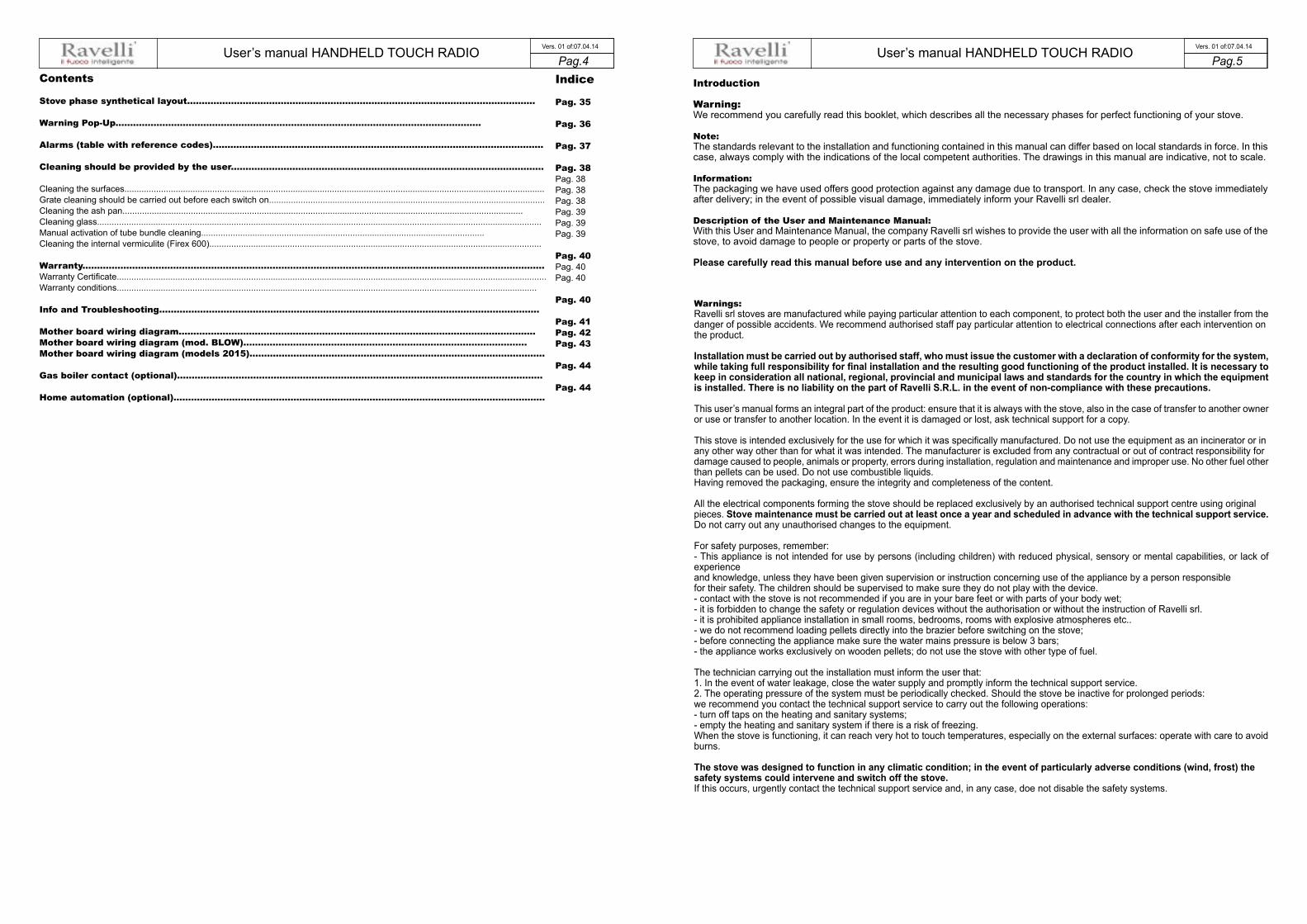
Contents
Stove phase synthetical layout.......................................................................................................................
Warning Pop-Up.............................................................................................................................
Alarms (table with reference codes).................................................................................................................
Cleaning should be provided by the user...........................................................................................................
Cleaning the surfaces............................................................................................................................................................................Grate cleaning should be carried out before each switch on.................................................................................................................Cleaning the ash pan....................................................................................................................................................................Cleaning glass......................................................................................................................................................................................Manual activation of tube bundle cleaning....................................................................................................................Cleaning the internal vermiculite (Firex 600)........................................................................................................................................
Warranty..............................................................................................................................................................Warranty Certificate................................................................................................................................................................................Warranty conditions............................................................................................................................................................................
Info and Troubleshooting..................................................................................................................................
Mother board wiring diagram..........................................................................................................................Mother board wiring diagram (mod. BLOW).................................................................................................Mother board wiring diagram (models 2015).....................................................................................................
Gas boiler contact (optional).............................................................................................................................
Home automation (optional)...............................................................................................................................
Indice
Pag. 35
Pag. 36
Pag. 37
Pag. 38Pag. 38Pag. 38Pag. 38Pag. 39Pag. 39Pag. 39
Pag. 40Pag. 40Pag. 40
Pag. 40
Pag. 41Pag. 42Pag. 43
Pag. 44
Pag. 44
Introduction
Warning:We recommend you carefully read this booklet, which describes all the necessary phases for perfect functioning of your stove.
Note:The standards relevant to the installation and functioning contained in this manual can differ based on local standards in force. In thiscase, always comply with the indications of the local competent authorities. The drawings in this manual are indicative, not to scale.
Information:The packaging we have used offers good protection against any damage due to transport. In any case, check the stove immediatelyafter delivery; in the event of possible visual damage, immediately inform your Ravelli srl dealer.
Description of the User and Maintenance Manual:With this User and Maintenance Manual, the company Ravelli srl wishes to provide the user with all the information on safe use of thestove, to avoid damage to people or property or parts of the stove.
Please carefully read this manual before use and any intervention on the product.
Warnings:Ravelli srl stoves are manufactured while paying particular attention to each component, to protect both the user and the installer from thedanger of possible accidents. We recommend authorised staff pay particular attention to electrical connections after each intervention onthe product.
Installation must be carried out by authorised staff, who must issue the customer with a declaration of conformity for the system,while taking full responsibility for final installation and the resulting good functioning of the product installed. It is necessary tokeep in consideration all national, regional, provincial and municipal laws and standards for the country in which the equipmentis installed. There is no liability on the part of Ravelli S.R.L. in the event of non-compliance with these precautions.
This user’s manual forms an integral part of the product: ensure that it is always with the stove, also in the case of transfer to another owneror use or transfer to another location. In the event it is damaged or lost, ask technical support for a copy.
This stove is intended exclusively for the use for which it was specifically manufactured. Do not use the equipment as an incinerator or inany other way other than for what it was intended. The manufacturer is excluded from any contractual or out of contract responsibility fordamage caused to people, animals or property, errors during installation, regulation and maintenance and improper use. No other fuel otherthan pellets can be used. Do not use combustible liquids.Having removed the packaging, ensure the integrity and completeness of the content.
All the electrical components forming the stove should be replaced exclusively by an authorised technical support centre using originalpieces. Stove maintenance must be carried out at least once a year and scheduled in advance with the technical support service.Do not carry out any unauthorised changes to the equipment.
For safety purposes, remember:- This appliance is not intended for use by persons (including children) with reduced physical, sensory or mental capabilities, or lack of experienceand knowledge, unless they have been given supervision or instruction concerning use of the appliance by a person responsiblefor their safety. The children should be supervised to make sure they do not play with the device.- contact with the stove is not recommended if you are in your bare feet or with parts of your body wet;- it is forbidden to change the safety or regulation devices without the authorisation or without the instruction of Ravelli srl.- it is prohibited appliance installation in small rooms, bedrooms, rooms with explosive atmospheres etc..- we do not recommend loading pellets directly into the brazier before switching on the stove;- before connecting the appliance make sure the water mains pressure is below 3 bars;- the appliance works exclusively on wooden pellets; do not use the stove with other type of fuel.
The technician carrying out the installation must inform the user that:1. In the event of water leakage, close the water supply and promptly inform the technical support service.2. The operating pressure of the system must be periodically checked. Should the stove be inactive for prolonged periods:we recommend you contact the technical support service to carry out the following operations:- turn off taps on the heating and sanitary systems;- empty the heating and sanitary system if there is a risk of freezing.When the stove is functioning, it can reach very hot to touch temperatures, especially on the external surfaces: operate with care to avoidburns.
The stove was designed to function in any climatic condition; in the event of particularly adverse conditions (wind, frost) thesafety systems could intervene and switch off the stove.If this occurs, urgently contact the technical support service and, in any case, doe not disable the safety systems.

User’s manual HANDHELD TOUCH RADIO User’s manual HANDHELD TOUCH RADIOPag.6 Pag.7 Vers. 01 of:07.04.14 Vers. 01 of:07.04.14
Safety information
The stove must be installed and inspected by specialist staff trained by head office. Please carefully read this user and maintenancemanual before installing and operating the stove. If you require further clarification, contact your nearest Ravelli srl dealer.The stove must be located indoors, never outdoors. Because it is controlied by an electronic board, it enables completely automatic anduncontrolled combustion: in fact, the control panel regulates activation, the 5 power levelsand switch off phase, guaranteeing safe functioning.Most of the hot ash falls into a pan via the basket used for pellet combustion. Checkcheck, on a daily basis, if the basket is clean, because not all pellets are of the highest quality and they can leave residues which aredifficult to remove.The glass is equipped with a special air wash for self-cleaning: yet, it is impossible to avoid a slight yellowish film on the glass aftersome hours of functioning.As already mentioned previously, the stove should be powered with pellets with diameter of 6 mm, but it can also operate with pelletswith different diameter: in this case, contact your Ravelli dealer for technical advice.
NOTE
• Prepare the installation location of the stove according to local, national and European regulations. • The stove must only be powered using high quality pellets with a diameter of 6 mm as described in the dedicated chapter. The stove cannot burn traditional wood. It is forbidden to use the stove as an incinerator. DANGER OF FIRE!!! • Installation, electrical connection, verification of functioning and maintenance must be carried out by qualified and author-
ised staff. • Improper installation or poor maintenance (non-conformity with what is reported in the following booklet) may cause dam-
age to people or property. In this condition, RAVELLI SRL is released from all civil or criminal liability. • Before connecting the stove to electrical power, the connection of the discharge tubes (specifically for pellet stoves, not in alumini-
um) with the flue must be complete. • The protection grid placed inside the pellet tank must never be removed. • There must be a sufficient exchange of air in the room in which the stove is installed. • Never open the door of the stove when functioning. DANGER OF FIRE!!! • It is forbidden to operate the stove with the door open or with the glass broken. DANGER OF FIRE!!! • When the stove is working, the surfaces, the glass, the handle and the tubes are very hot: during functioning these parts can only be
touched using adequate protective equipment. • Do not switch on the stove without firstly carrying out a daily inspection as described in the MAINTENANCE chapter of this
manual. • Do not dry washing on the stove. Any washing lines or similar must be kept an appropriate distance from the stove. DAN-
GER OF FIRE!!! • Scrupulously follow the maintenance schedule. • Do not switch off the stove by disconnecting the electrical mains. • Do not clean the stove until the structure and ash are completely cold. • Carry out all operations in a completely safe and calm manner.
Responsibilities By handing over to the end user this manual, Ravelli srl denies all liability, both civil and criminal, for accidents arising from non-compli-ance with instructions contained in it. Ravelli srl denies all liability deriving from improper use of the stove, from incorrect use by the user, from unauthorised changes and/or repairs and from use of non-original spare parts. The manufacturer declines all direct and indirect civil and criminal liability due to: - poor maintenance - non-compliance with the instructions contained in this manual - use not complying with safety directives - installation not complying with the standards in force in the country - installation by unqualified and untrained staff - changes and repairs unauthorised by the manufacturer - use of non-original spare parts - exceptional events
Spare parts Exclusively use original spare parts. Do not wait for the components to deteriorate before replacing them. Replace a worn component before it is completely broken to prevent any accidents due to sudden breakage of the components. Carry out periodic maintenance controls as described in the dedicated chapter
General information
What are wood pellets? Pellets are composed of woodchip and sawdust produced in joineries. The material used cannot contain any foreign substances such as glue, lacquer or synthetic substances. The wood is pressed using a perforated matrix: due to the high pressure the sawdust heats to activate the natural binders in the wood; in this way, the pellet maintains its shape, also without adding artificial substances. The density of the wood pellets varies based on the type of wood and can exceed 1.5 - 2 times that of natural wood. The cylindrical sticks have a diameter of 4 - 10 mm. and a variable width between 10 and 30 mm.
LengthDiameterReal weightHeat powerResidual humidityAshSpecific weight
: approx. 10 - 30 mm: approx. 4 - 10 mm: approx. 650 Kg/m³: approx. 4.9 kWh/Kg: approx. 6 - 12 %: <1.5%: >1.0 Kg/dm³
Pellets must be transported and stored in dry places. On contact with humidity they swell, becoming unusable: therefore it is necessary to protect them from humidity both during transport and storage. Ravelli srl recommends a pellet with a diameter equal to 6 mm. If you wish to use a pellet type with a different diameter con-tact the support centre to carry out the due regulations on the stove.
Excerpt from the DIN PLUS standard: This standard requires that the pellet is produced with starting material “virgin wood” free of contaminants (glues, paints, preserva -tives). Manufacturing, however, alloews the use of vegetable non-chemically modified thermal agglutinating agents such as wheat flour, rye or starch, which cannot however exceed 2% of the product.
The pellets can be light or dark, usually packed in bags bearing the manufacturer’s name, the main features and the marking of DIN Plus standard.
How is a stove made?
12
11
10
9
8
7
6
5
4
3
2
1
1 Pellet tank cover
2 Design coating
3 Pellet tank
4 Pelelt infeed screw
5 Smoke extractor
6 Pellet gear motor
7 Air intake duct with flow meter
8 Hot air output grid
9 Vermiculite
10 Front door
11 Ignition resistance
12 Cast iron brazier
13 Fume duct
14 Stove base
15 Air intake duct with flow meter
13
14

User’s manual HANDHELD TOUCH RADIO User’s manual HANDHELD TOUCH RADIOPag.8 Pag.9 Vers. 01 of:07.04.14 Vers. 01 of:07.04.14
Combustion
Combustion is nothing more than a chemical reaction in which two agents, called the fuel and the oxidizing agent, combine to produce a new substance. A considerable amount of heat is also produced from this reaction (concept of pellet stove functioning). To facilitate the aforementioned expression, we can take into consideration this practical diagram called the “combustion triangle”; it consists of three elements which are necessary to produce a combustion reaction. These three elements are:
• fuel (pellets) • oxidizing agent (oxygen in air) • trigger (electrical resistor on switch on)
The fuel and the oxidizing agent must be in adequate proportions because combustion is restricted to the so-called “inflammability field”.The reaction between the fuel and the oxidizing agent is not spontaneous, but occurs using an external trigger. The trigger can be repre-sented for example by a heat source or a spark. The trigger represents the ignition energy necessary for the reagent molecules to start the reaction and must be provided externally (electrical resistor on switch on). Then, the energy released by the reaction makes self-sustainment possible.Three types of combustion are reported below, the correct one is reported in Figure 3:
INCORRECT combustion, flame too drawn, in “blowtorch” style with a high quality ofincandescent pellets coming out of the grate. Correct the pellet/air set by reducing thepercentage of air (from 0 to -5); if not sufficient, also increase the percentage of fallingpellets (from 0 to +5) to arrive to the condition in Figure 3.If the changes made to the settings do not bring the stove to the right combustion conditions in Figure 3, contact the Technical Support Centre.
INCORRECT combustion, “spring” flame in “wood stove” style with high quantity of pelletsnot burning on the grate. Firstly, check the door is closed and the ash pan. Secondly,correct the pellet/air set by increasing the percentage of air (from 0 to +5); if not sufficient,also reduce the percentage of falling pellets (from 0 to -5) to arrive to the condition inFigure 3.If the changes made to the settings do not bring the stove to the right combustion condi-tions in Figure 3, contact the Technical Support Centre.
CORRECT combustion, lively yellow/white flame with a minimum quantity of pellets onthe grate.Ideal combustion which does not require changes.
Figure 3 shows a flame produced by a stove with functioning power set on the maximum value 5.
Fig. 1
Fig. 2
Fig. 3
OXYGEN HEAT
FUEL
Safety devices The stove is equipped with sophisticated safety systems, which avoid damage to the stove and/or the home in the event of breakage of a single piece or faults on the flue. In any case, if an anomaly occurs, the pellets are immediately stopped from falling and the switch off phase activates. The corresponding alarm is shown on the display. It is possible to see the details in the chapter dedicated to alarms.
Technical standards and Directives
All Ravelli srl products are manufactured according to thedirectives: • 89/106 CEE manufacturing materials • 73/23 CEE electrical safety • 2006/42/ CEE machines • 2004/108 CEE Electromagnetic Compatibility
And according to the standards: • EN 14785 • EN 60335.1 EN 50165 • EN 292 EN 294 EN 349 • EN 55014.1 EN 61000-3-2 EN 61000-3-3 • EN 55014.2
Stove installation
Advice for installationBecause of the frequent accidents caused by the malfunctioning of the flues in residential buildings, this chapter has been draftetin collaboration with Assocosma (association of stove/sweepping technicians and specialists of the field) in order to facilitate theinstaller to build a system able to evacuate fumes in accordance with the regulations in force.
- Marking standard Directive CE 89/106 D.P.R. 246 regarding the exclusive use of CE certified material;- UNI 10683/2012 for the installation of a biomass fire box;- UNI/TS 11278 regarding the selection of material (only for pellet stoves different than V2)- UNI 10845:2000 (standard regarding gas use regulations) for piping and the relative check of skylight well (material used, wearcondition, etc.) and safety distances to be observed from flammable materials;- UNI 10847:2000 Flue systems for individual generators powered by liquid and solid fuels - Maintenance and Control - Guidelinesand Procedures- UNI 7129/08 (standards regarding depressurized chimneys, excerpt from gas-related regulations) regarding the type, height andpositioning of the chimney cap;- UNI/EN 1443 regarding the installation with the minimum essential chimney requirements met (followed by the compilation offume dataplate to be affixed to the same).
Approved installations Fireplaces, stoves and barbecues cannot be installed in areas in which are present and functioning equipment fueled by liquid andgas type A and type B (for classification see UNI 10642 and UNI 7129).It is forbidden to install the stove in rooms used for cooking, if there are:- collective type ventilation ducts;- blowers/vacuums connected to the outside and/or equipment that can depressurize the room. It is forbidden:to install the stove in rooms at risk of fire such as garages and garages, bedrooms (only watertightinstallation) or studios (unless installed in a hermetically sealed combustion chamber).
EXCERPT OF STANDARD UNI/EN 1443
System compatibility check Compatibility check of the system should be carried out before any installation or commissioning intervention. The adjacent, side and rear walls and the supporting surface must be made of non-combustible and non sensitive to heat material. The stove can be installed next to flammable materials or materials sensitive to heat as long as the required safety conditions are met by interposing an insulating and non-flammable material; this operation is provided in the instructions supplied by the manufacturer. When the installation instructions are not available, the installer will have to secure the appliance and shall be liable for its commis-sioning. Before installation you should check the position of the stove, flue or exhaust terminal devices to make sure the following are complied with: - Installation restrictions - Legal distances - Limitations provided by local administrative regulations or specific provisions of the local bodies. - Conventional limitations imposed by the residence regulations, easement or contracts.
After surveying the installation place, the installer should check the following: - the type of appliance; - the compatitbility of the installation place with the appliance in terms of minimum installation volume indicated by the - the instructions of the manufacturer of the heat generator regarding the requirements of the fume exhaust system for the deactivation of the heat generator; - the internal cross section of the fume duct, the composing materials, the evenness of the cross section, the absence of obstructions; - height and length on vertical plane of the chimney; - the existence and compliance of chimney terminal; - the possibility to fit external air vents and the dimensions of existing vents.
The complete flue exhaust system must be supplied and installed in compliance with the regulations issued by the standardization bodies and should be installed according to state-of-the-art standards.
Air vent: It is used to fuel the fire box and input air into the room; it should be fitted directly from the outside (not through other rooms, garage etc.; its cross section should be equal or 1/4 higher than chimney section by minimum 80 sq.cm for stoves and thermo-stoves (UNI1475) and 100 sq. cm for boilers (UNI303-5). Manufacturer’s and designer’s instructions should be however complied with at all times. Also check that the drilling position of the wall allows the intake of fresh air, making sure that no harmful exhausts fumes return into the room (radon gas, ect.).

User’s manual HANDHELD TOUCH RADIO User’s manual HANDHELD TOUCH RADIOPag.10 Pag.11 Vers. 01 of:07.04.14 Vers. 01 of:07.04.14
Chimney cap (UNI 7129/08): - Fume exhaust cross section should be twice the diameter of the chimney; - Have a structure suitable to prevent water or snow from entering; - Be built so that in the presence of wind it still ensures fume exhaust (wind-proof
chimney cap) - Function always as a static suction system facilitating fume dispersion - the release quota is measured between the lower covering layer and the lower point
of the fume release into environment, ouside the reflux area to prevent counter-pressures;
- Be built at safe distance from antennas or parabolic antennas never be used as a support;
Safe distances for proper installation of chimney terminal:
Fume duct and fittings:For heat generating devices equipped with an electric fume exhaust fan you must follow the installation instructions of the manufac-turer regarding the maximum length and number of bends of the exhaust ducts.In case the maximum values are not available , you should follow the provisions below:- Horizontal sections should have a minimum slope of 3% upwards (45° bends are recommended)- The length of the horizontal section should be minimum and its plan projection should not exceed 3 metres- The number of direction changes including the one required to use the T fitting and insert the chimney should not be higher than3.- This section should have constant diameter and equal at fire box outlet up to the fitting into the flue.- It is forbidden to use flexible metal and cement fibre tubes and pressurization should be ensured at all timesIn any case, the fume ducts should be sealed and protected against combustion products or condenstae as well asinsulated if passing outside the installation room.It is not allowed to mount manually regulated draught devices onto appliances with forced draught.
Flue:- It should be made of suitable materials to ensure resistance to normal mechanical and chemical stress,and should be properly insulated to prevent condensate; therefore, it should be provided with thermal insulation (product standardfor flue UNI 1856 |1|2 and standard for materials used UNI/TS 11278).- Be free of narrowing throughout its length;- Be properly spaced by means of air gaps and insulated with non flammable materials.- Maximum bends allowed are at 45°.- the flue installed inside the house should be insulated and can be inserted into a chimney terminal as long as the piping standards are being complied with (UNI 10845).- The fume duct should be connected to the chimney by means of a T fitting with a collection chamber fitted with inspection glass to check the combustion residues and condensate collection. Flue dataplate:Supplied with the chimney, it identifies:- The manufacturer;- The CE marking;- designation of the product as per standard UNI 1856(xx)There is also a part to be completed by the installer which certifies the suitability of the chimney to the product (stove) installed,
LEGEND:
T: Indicates the temperature class (T80 - T200 - etc.); N/P/H: Indicates the protection class (N-->negative - P--> Positive - H-->High pressure; “x”--> indicates the loss allowed whereas 1 is the most restrictive); D/W: It indicates the condenstae resistance class (D-->for dry use - W-->for wet use); V: Corrosion resistance class (V1-->gaseous fuels; V2-->liquid fuels; V3-->solid fuels; Vm--> test not performed); LX/X: Indicates the type of material used and the thickness in hundredths of millimetres (i.g.: L50050 indicates L50-->Stainless Steel AISI 316 and 050-->thickness 0.5mm); G/O: Indicates the fire resistance class of unburnt products (G-->YES; O-->NO) and the value between brackets indicates the dis-tance from flammable materials.
Therefore, the dataplate to be compiled following the requests for a pellet stove shall be:
DESIGNATION EN 1443: T400 N1 D 3 G(xx)IT IS FORBIDDEN TO DISCHARGE FLUES THROUGH A DIRECT SYSTEM OR ANY OTHER DRAIN SYSTEMNOT PROVIDED BY THE STANDARDS MENTIONED ABOVE
1) DESIGNATION EN 1443: T400 N1 D 3 G(30) 2) DIAMETER: 100 mm 3) DISTANCE FROM FLAMMABLE MATERIAL: 30 mm 4) INSTALLER (name/address): Mario Bianchi Via Rossi 24 Calcinate (BG) 5) DATA: 27/01/2014....................................................................................................................... WARNING: THIS LABEL SHOULD NOT BE REMOVED OR MODIFIED
Last two digitsof the year in which themarking has been affixed
Identificationnumber
Certificate number
Designationstated bymanufacturer
Section compiledby the installer
NAME and BRANDMANUFACTURER:
CERTIFICATE CE:01234-CPD-0999Chimney System: EN 1856/1-2 T400 N1 D v2 l50050 G(30)
SECTION RESERVED TO THE INSTALLER
xx
01234
The flue system of the pellet stoves operate with negative pressure (see LH of the roof) the part marked with gray is the reflu area and the chimney terminal should therefore release the fume above these area.
Chimney output usable section
Internal chimney section
Symbol
Symbol
SymbolDormer window (2) Sideways distance from the dormer window
Height above the dormer window ridge
Front distance from the dormer window
Distance from the smaller row of openings or windows
Height above openings or windows
Distance from the top or side row of openings or windows
Skylight (1)
Description
Description(mm)
Description
Clearance (mm)
Clearance (mm)
Outlet area (mm)
(See figure 8) Height measured in vertical plane
Height above the obstacle
Distance measured at 90° from roof surface
Height above roof ridge
User’s manual HANDHELD TOUCH RADIO User’s manual HANDHELD TOUCH RADIOPag.12 Pag.13 Vers. 01 of:07.04.14 Vers. 01 of:07.04.14
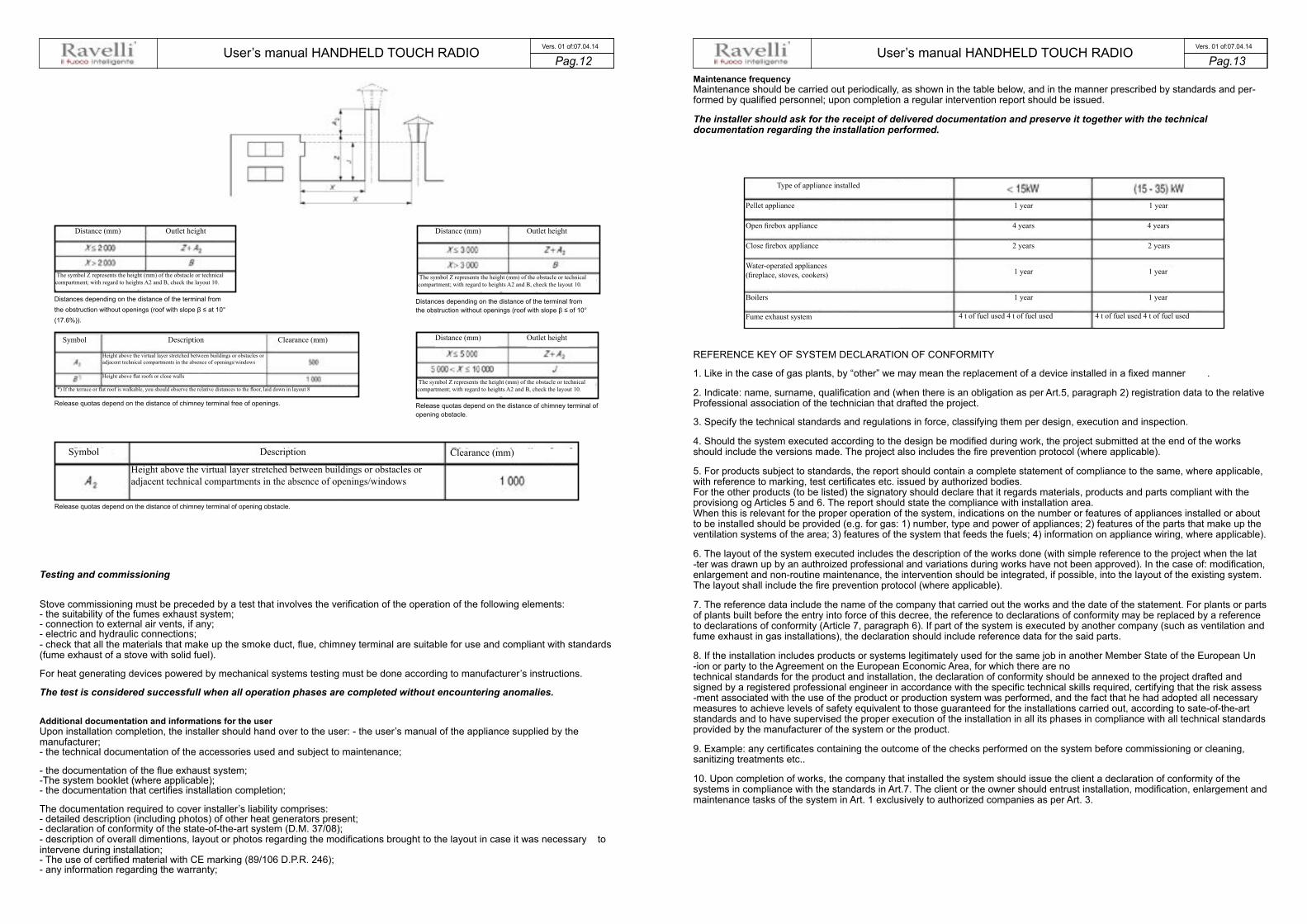
Maintenance frequency Maintenance should be carried out periodically, as shown in the table below, and in the manner prescribed by standards and per-formed by qualified personnel; upon completion a regular intervention report should be issued.
The installer should ask for the receipt of delivered documentation and preserve it together with the technical documentation regarding the installation performed.
Distances depending on the distance of the terminal fromthe obstruction without openings (roof with slope β ≤ at 10°(17.6%)).
Distances depending on the distance of the terminal fromthe obstruction without openings (roof with slope β ≤ of 10°
Release quotas depend on the distance of chimney terminal free of openings. Release quotas depend on the distance of chimney terminal ofopening obstacle.
Release quotas depend on the distance of chimney terminal of opening obstacle.
Testing and commissioning
Stove commissioning must be preceded by a test that involves the verification of the operation of the following elements: - the suitability of the fumes exhaust system; - connection to external air vents, if any; - electric and hydraulic connections; - check that all the materials that make up the smoke duct, flue, chimney terminal are suitable for use and compliant with standards (fume exhaust of a stove with solid fuel).
For heat generating devices powered by mechanical systems testing must be done according to manufacturer’s instructions.
The test is considered successfull when all operation phases are completed without encountering anomalies.
Additional documentation and informations for the user Upon installation completion, the installer should hand over to the user: - the user’s manual of the appliance supplied by the manufacturer; - the technical documentation of the accessories used and subject to maintenance;
- the documentation of the flue exhaust system; -The system booklet (where applicable); - the documentation that certifies installation completion;
The documentation required to cover installer’s liability comprises: - detailed description (including photos) of other heat generators present; - declaration of conformity of the state-of-the-art system (D.M. 37/08); - description of overall dimentions, layout or photos regarding the modifications brought to the layout in case it was necessary to intervene during installation; - The use of certified material with CE marking (89/106 D.P.R. 246); - any information regarding the warranty;
REFERENCE KEY OF SYSTEM DECLARATION OF CONFORMITY
1. Like in the case of gas plants, by “other” we may mean the replacement of a device installed in a fixed manner .
2. Indicate: name, surname, qualification and (when there is an obligation as per Art.5, paragraph 2) registration data to the relative Professional association of the technician that drafted the project.
3. Specify the technical standards and regulations in force, classifying them per design, execution and inspection.
4. Should the system executed according to the design be modified during work, the project submitted at the end of the works should include the versions made. The project also includes the fire prevention protocol (where applicable).
5. For products subject to standards, the report should contain a complete statement of compliance to the same, where applicable, with reference to marking, test certificates etc. issued by authorized bodies. For the other products (to be listed) the signatory should declare that it regards materials, products and parts compliant with the provisiong og Articles 5 and 6. The report should state the compliance with installation area. When this is relevant for the proper operation of the system, indications on the number or features of appliances installed or about to be installed should be provided (e.g. for gas: 1) number, type and power of appliances; 2) features of the parts that make up the ventilation systems of the area; 3) features of the system that feeds the fuels; 4) information on appliance wiring, where applicable).
6. The layout of the system executed includes the description of the works done (with simple reference to the project when the lat -ter was drawn up by an authroized professional and variations during works have not been approved). In the case of: modification, enlargement and non-routine maintenance, the intervention should be integrated, if possible, into the layout of the existing system. The layout shall include the fire prevention protocol (where applicable).
7. The reference data include the name of the company that carried out the works and the date of the statement. For plants or parts of plants built before the entry into force of this decree, the reference to declarations of conformity may be replaced by a reference to declarations of conformity (Article 7, paragraph 6). If part of the system is executed by another company (such as ventilation and fume exhaust in gas installations), the declaration should include reference data for the said parts.
8. If the installation includes products or systems legitimately used for the same job in another Member State of the European Un -ion or party to the Agreement on the European Economic Area, for which there are no technical standards for the product and installation, the declaration of conformity should be annexed to the project drafted and signed by a registered professional engineer in accordance with the specific technical skills required, certifying that the risk assess -ment associated with the use of the product or production system was performed, and the fact that he had adopted all necessary measures to achieve levels of safety equivalent to those guaranteed for the installations carried out, according to sate-of-the-art standards and to have supervised the proper execution of the installation in all its phases in compliance with all technical standards provided by the manufacturer of the system or the product.
9. Example: any certificates containing the outcome of the checks performed on the system before commissioning or cleaning, sanitizing treatments etc..
10. Upon completion of works, the company that installed the system should issue the client a declaration of conformity of the systems in compliance with the standards in Art.7. The client or the owner should entrust installation, modification, enlargement and maintenance tasks of the system in Art. 1 exclusively to authorized companies as per Art. 3.
Distance (mm) Distance (mm)
Distance (mm)Symbol
Symbol
Description
Description
Height above the virtual layer stretched between buildings or obstacles or adjacent technical compartments in the absence of openings/windows
Height above the virtual layer stretched between buildings or obstacles or adjacent technical compartments in the absence of openings/windows
Height above flat roofs or close walls
*) If the terrace or flat roof is walkable, you should observe the relative distances to the floor, laid down in layout 8
Clearance (mm)
Clearance (mm)
The symbol Z represents the height (mm) of the obstacle or technical compartment; with regard to heights A2 and B, check the layout 10.
The symbol Z represents the height (mm) of the obstacle or technical compartment; with regard to heights A2 and B, check the layout 10.
The symbol Z represents the height (mm) of the obstacle or technical compartment; with regard to heights A2 and B, check the layout 10.
Outlet height Outlet height
Outlet height
Type of appliance installed
Pellet appliance
Open firebox appliance
Close firebox appliance
Boilers
4 t of fuel used 4 t of fuel used
1 year
1 year
2 years
4 years 4 years
2 years
1 year 1 year
1 year
1 year
4 t of fuel used 4 t of fuel usedFume exhaust system
Water-operated appliances (fireplace, stoves, cookers)

User’s manual HANDHELD TOUCH RADIO User’s manual HANDHELD TOUCH RADIOPag.14 Pag.15 Vers. 01 of:07.04.14 Vers. 01 of:07.04.14
This type of installation (See Figure 1) requires the chimneyto be insulated despite the fact that the entire duct is instal-led inside the building. Moreover, the structure should be inserted into a properly ventilated skylight well.
At the bottom of the chimney is provided an inspection coversuitably isolated from wind and rain.
It is not recommended to install a 90° curve as the first initialpiece, since the ash could quickly obstruct the smoke passa-ge, causing problems for stove suction. (See fig. 2)
Fig.2Fig.1
This type of installation (See Fig. 5) does not need an insu-lated flue for the section inside the home, while the sectionplaced outside must have insulated tubing. In the lower partof the flue, inside the house, was nstalled a T fitting with aninspection cap; another one was mounted outside to enableinspection of the external section.
It is not recommended to install two 90° curves since theash could quickly obstruct smoke passage, compromisingstove’s draught. (See fig. 2)
NO
Fig.3
Examples of installation of a pellet stoveDECLARATION OF CONFORMITY OF THE STATE-OF-THE-ART SYSTEM
As per para.I of Art. 7 of Ministerial Decree 37 of January 22, 2008 no. 20
The undersigned ___________________________________ owner or legal representative of the company ___________ (company’s name)___________ operating in the handcraft sector with premises in ______________________________________ municipality ___________________________ prov. ( ___ ) phone _______________________________ VAT no _______________________________________
□ registered in the Registry of Companies (DPR 7/12/95 no.581 of CCIAA of TV no. xxx □ registered in the Provincial Handicraft Enterprises (L. 8.8.1985, no.443) of TV no. xx
system executed by (schematical description, project layout):_________________________________________________
______________________________________________________________________________________________
______________________________________________________________________________________________
______________________________________________________________________________________________
intended as: □ new system □ makeover □ upgrade □non-routine
maintenance □ other(1) ................................................................
Commissioned by__________________________________ installed at the premises in the municipality of ____________________________ prov. ( ___ )
street_____________________________________ floor ____internal, owned by ________(name, surname or name of the company and ad-dress)______
in the building designated as: □ industrial □ civil □ trade □ other uses
DECLARES under its sole responsibility that the machine was built in compliance with state-of-the-art standards in accordance with the provisions of Article 6, taking into account the operating conditions and the designated uses of the building, having in particular: □ observed the project drafted as per Art.5 by (2) ......................................................................................................................... □ followed the technical standard specific to its use as (3) UNI10683/05 UNI10845 UNI/TS11278 UNI/EN1443 UNI7129/08 □ installed parts and materials suitable for the place of installation (Art.5 and 6) □ inspected the system for safety purposes and the functionality with positive outcome, having carried out the checks required by the standards and the provisions of the law.
Mandatory annexes: □ designed according to articles 5 or 7 (4)
□ report of the types of materials used (5)
□ layout of the installation made (6)
□ reference to previous or partial declarations of conformity, already existing (7): executed by the company ............................................................................. date ........... □ copy of the certificate of acknowledgement of technical and professional requirements □ certificate of conformity for the system executed with non-standard materials or systems (8).
Optional annexes: Photographic Documentation. Use and maintenance manual of the fireplace, the Fume dataplate and booklet of the generator , declaration of insulation compliance, combustion analysis, draught test, local ventilation and CO verification and chimney seal test
DENIES all liability for injuries or damages to property arising from tampering with the system, by third party or due to lack of maintenance or repair (9) .
Date ___________________ The technical manager __________________________ The undersigned ____________________________
WARNINGS FOR THE BUYER: liability of the buyer or the owner,art.8(10)
The undersigned _________________________________________ buyer of the works/owner of the building declares to have received _____
Skylight
T joint for condensate
Protection from rain
Insulated flue
Grill that enables air passage into the skylight well with open -ing for inspecting the chimney
Ash collected in 90° bend
Smoke duct: use of non insulated tube
Protection from rain
Insulated flue
T-fitting
Combustion ashes collection chamber + condensate drain
T joint for condensate
User’s manual HANDHELD TOUCH RADIO User’s manual HANDHELD TOUCH RADIOPag.16 Pag.17 Vers. 01 of:07.04.14 Vers. 01 of:07.04.14
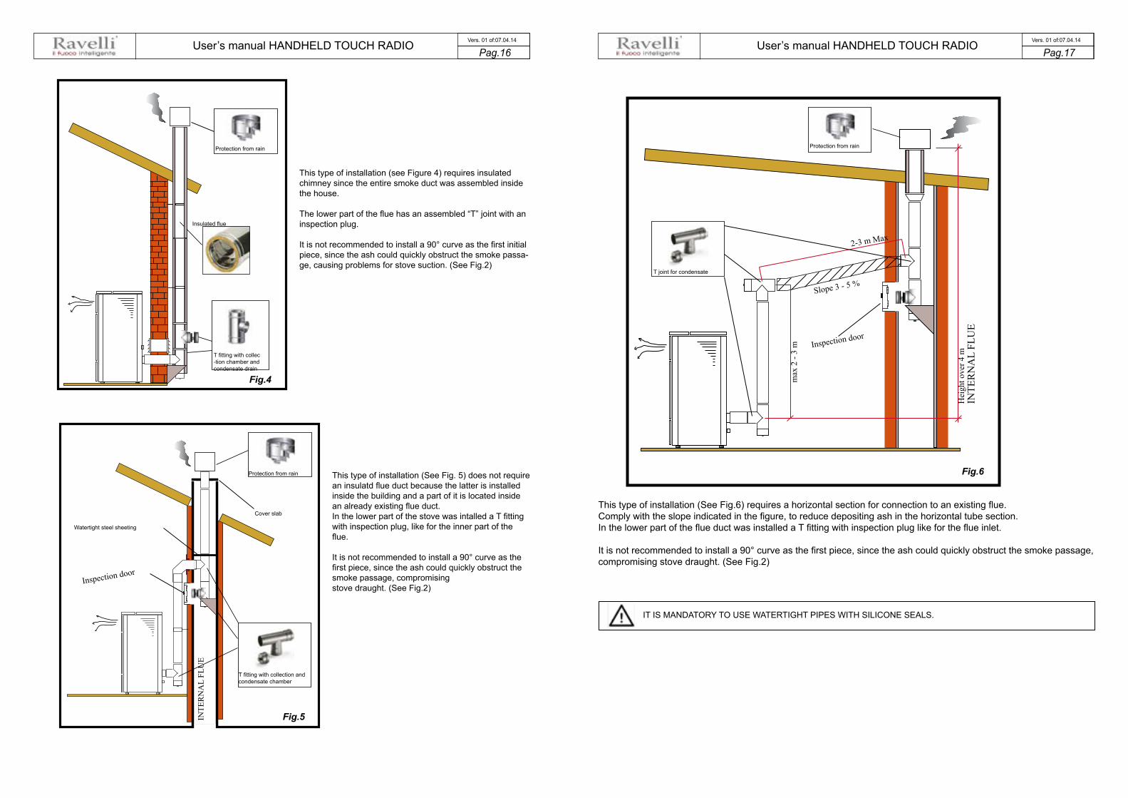
This type of installation (see Figure 4) requires insulatedchimney since the entire smoke duct was assembled insidethe house.
The lower part of the flue has an assembled “T” joint with aninspection plug.
It is not recommended to install a 90° curve as the first initialpiece, since the ash could quickly obstruct the smoke passa-ge, causing problems for stove suction. (See Fig.2)
Fig.4
This type of installation (See Fig. 5) does not require an insulatd flue duct because the latter is installed inside the building and a part of it is located inside an already existing flue duct.In the lower part of the stove was intalled a T fittingwith inspection plug, like for the inner part of theflue.
It is not recommended to install a 90° curve as thefirst piece, since the ash could quickly obstruct thesmoke passage, compromisingstove draught. (See Fig.2)
Fig.5
This type of installation (See Fig.6) requires a horizontal section for connection to an existing flue.Comply with the slope indicated in the figure, to reduce depositing ash in the horizontal tube section.In the lower part of the flue duct was installed a T fitting with inspection plug like for the flue inlet.
It is not recommended to install a 90° curve as the first piece, since the ash could quickly obstruct the smoke passage, compromising stove draught. (See Fig.2)
Fig.6
Protection from rain
IT IS MANDATORY TO USE WATERTIGHT PIPES WITH SILICONE SEALS.
Protection from rain
Insulated flue
T fitting with collec -tion chamber and condensate drain
Watertight steel sheeting
Inspection door
INTE
RN
AL
FLU
E
Protection from rain
Cover slab
T fitting with collection and condensate chamber
T joint for condensate
max
2 -
3 m
2-3 m Max
Slope 3 - 5 %
Inspection door
Hei
ght o
ver 4
m
INTE
RN
AL
FLU
E

User’s manual HANDHELD TOUCH RADIO User’s manual HANDHELD TOUCH RADIOPag.18 Pag.19 Vers. 01 of:07.04.14 Vers. 01 of:07.04.14
Examples of installation of a pellet insert
In this type of installation we can notice that the fitting was used to enable connecting the insert to the chim-ney (so-called “bayonet” mount).
For safety reasons and to ensure proper operation, we recommend you fit pipes into the chimney. (Fig.7)
It is recommended to perfectly match the insert with the fitting, to prevent leaks of smoke during the work phase.
Fig.7
Fig.8
Exploded view of T fit
Protection from rain
Wiring
Connect the power cord to the back of the stove and then to a wall socket. The I/O switch in the figure should be set to I to power the stove. If voltage is not supplied check the state of the fuse installed in the box below the switch (4A fuse). During the periods of inactivity, we recommend you disconnect the power cord of the stove.
Preliminary Operations
NEVER INSERT INTO THE TANK OTHER KIND OF FUEL OTHER FROM THE PELLETSCOMPLYING WITH THE SPECIFICATIONS BELOW
The handheld set is shown in the picture below:Description of the handheld set:
The information below will allow you to become familiar with the product and achieve the best performance.
How to insert the batteries in the handheld set:Remove the protective cover of the battery on the back of the remote control as shown in Figure A, and insert the 3 batteries(mini pen style battery AAA 1.5V) in the housing of the handheld set and observe the poles. Install the battery protective coveras shown in figure B
The handheld set, after a short screen showing the Ravelli logo, will list the languages available in the menu.
Select the desired language using the scroll keys and confirm your selection with the confirmation button.
1 Increase button “UP” (selection key)
2 Decrease key “DOWN” (selection key)
3 ON/OFF or reset from “Sleep” mode key.
4 Display
5 Key for accessing the MENU and back
6 Confirmation key
1
2
5
6
4
3
Figure A Figure B
Here you can see the possibility to slidethe insert; this operation can only be performedwith the stove turned off for loading pellets or duringregular checks. (Fig.8)
IT IS STRICTLY FORBIDDENTO REMOVE THE STOVE DURINGTHE WORK PHASES; THE FUMEMAY DISPERSE INTO THE
In “Sleep” mode, the handheld setscreen is obscured, keeping howeveractive the radio communication withthe stove to reduce battery con-sumption.
T fitting with inspection ash collector cap
Flue
Protection from rain
Pipe
Flue
Pipe
What to check befor turning on the stove Make sure you have removed all parts that pose the risk of burns from the combustion chamber or glass (various instructions or stickers). Before turning on the stove, make sure you have fitted the grate on the support base and check that the door and the ash drawer are properly close. How to load the pellets Fuel supply consists in the insertion of pellets from the top of the stove, by opening the door. During pellet loading prevent the pel-let bag from coming into contact with hot surfaces.

User’s manual HANDHELD TOUCH RADIO User’s manual HANDHELD TOUCH RADIOPag.20 Pag.21 Vers. 01 of:07.04.14 Vers. 01 of:07.04.14
2
3
1
2
3
1
FIRST INSTALLATION?
PRESS THE KEY RADIO ADJ ON THE STOVE
YES
MENU USER USER
SETTINGS
SETTINGSDATE-TIME
USER COMFORT CLIMA
MANUFACTURER ENGINEER
ENABLE EXT. TH.CONTRAST
FW VERSIONADJUST
LANGUAGE
SCREW FEEDINGCHRONOTHERMOSTAT
AIR-PELLET SETSTOVE STATE
Handheld touch radio initialization In order to operate correctly, the handheld set should be interfaced with the electronic board installed inside the stove. For this reason, on display appears the following message:
If the handheld set is used for the first time, select YES using the selection keys and confirm with the dedicated key.
On the display of the handheld set appears the following:
Hold down for a few seconds the button of radio communication (RADIO ADJ) of the PCB, located on the back of the stove, to initialize the device.
The flashing yellow LED indicates that the circuit board is waiting to receive the signal from the handheld set.
By pressing the enter key on the handheld set, the components start communicating with each other. A check sign on the display, accompanied by a sound signal, shows that the initialization of the handheld set has been completed sucessfully .
When you replace the batteries, you do not have to run the initialization procedure of the handheld set. In this case, when on display appears the message “FIRST INSTALLATION ?”, select NO and press the confirmation key.
Description of the display The display of the handheld set is described below (in stand-by mode):
After 5 minutes of inactivity, the display of the handheld set turns dark, switching to “SLEEP” mode, while maintaining the radio connection with the stove. By pressing the key ON/OFF, the display becomes active again.
The first pressure of any key with the display active, lights up its backlight, but it is not, however , considered a command.
The display is subdivided into three parts:
1. It shows the current room temperature measured by the handheld set. Moreover, if you press the DOWN scroll key you will display the temperature settings that can be changed using the two UP/DOWN keys. Any change made is confirmed automatically within 3 seconds from the change or by pressing the confirmation key. A sound signal indicates that the change has been con-firmed.
In the inactive phases (combined with the 3rd part of the display) indicates the state of the stove. In the active phases, it indicates the operating power of the stove. In addition, by pressing the DOWN scroll button, you can display the power settings, that can be edited using the two scroll keys UP/DOWN: The confirmation of any change takes place automatically within 3 seconds from the change or by pressing the con-firmation key. A sound signal indicates that the change has been confirmed.
Time and date setting Below are given the steps for accessing the relative menu.
Press the key “access menu” to access
the MENU page
Press the key “confirm” to access the SETTINGS page
Press the key “confirm”
to access the USER page
Press the key “con-firm”
to access the page DATE-TIME
Press the key “selection” for “selection”
to switch to the second page of USER MENU and select
SETTINGS.
Press the increase key to change every single value
Press the increase key to change every single value
Press “confirm” to confirm the settings and switch to the next value.
By pressing the key “back” for several times you will display the stand-by page.

User’s manual HANDHELD TOUCH RADIO User’s manual HANDHELD TOUCH RADIOPag.22 Pag.23 Vers. 01 of:07.04.14 Vers. 01 of:07.04.14
Loading the auger
MENU USER
SCREW FEEDING
SCREW FEEDING
CHRONOTHERMOSTATAIR-PELLET SET
STOVE STATE
USER
MANUFACTURER ENGINEER
MENU
USER
MANUFACTURER ENGINEER
USER USER
COMFORT CLIMA
COMFORT CLIMA
COMFORT CLIMA
COMFORT CLIMA
ENABLE COMFORT
ENABLE COMFORT
ENABLE COMFORT
RESTART DELTA
RESTART DELTA
SHUTDOWN DELAY
SHUTDOWN DELAY
SHUTDOWN DELAY SHUTDOWN DELAY
ENABLE COMFORT ENABLE COMFORT
COMFORT CLIMA DELTA COMFORT CLIMA DELTA
RESTART DELTASHUTDOWN DELAY
SETTINGS
SCREW FEEDINGCHRONOTHERMOSTAT
AIR-PELLET SETSTOVE STATE
ALWAYS EMPTY THE BRAZIER BEFORE TURNING THE STOVE ON AND ALWAYS CHECK THAT ALL NONE OF ITS HOLES IS CLOGGED NEVER EMPTY THE RBAZIER INSIDE THE HOPPER. FIRE HAZARD.
Carry out this operation to facilitate stove’s first start operations; You should also check that you have introduced pellets into the hopper and wait until the stove is in “SHUTDOWN” or “FINAL CLEANING” mode. The number expressed in sec-onds indicates the rotation time of the infeed screw during the first loading cycle. Once this time has elapsed, the infeed screw stops immediately and then pellets are emptied from the grate before turning on the equipment.
Below are given the steps for accessing the relative menu.
Press the key “access menu” to access
the MENU page
Press the key “confirm”
to access the USER page
At the end of the auger loading, the display shows 0 “and automatically switches to the USER menu page.
Press the key for several times until the Stand-by page is displayed.
Setting operating temperature and power: Set the two values following the indications given in the chapter “Description of thr display”
Turning the device on Keep the key ON/OFF pressed for a few seconds to turn on the stove.
Press CONFIRM to enable the rotation of the auger
The appearance of the message “ADJUST THE RDS SYSTEM” indicates that the initial parameter testing procedure and calibration has been unsuccessfully. This indication does not cause stove blockage (see the SIGNALLING POP UP section).
On the display of the handheld set appears the following:
Press and hold the ON/OFF button to turn off the stove door, and reset any alarms triggered.
In case the infeed screw operations described avobe have not been executed, the stove may fail to turn on. In this case, carry out the operations described above and empty the brazier and reset the alarm.
If the stove still fails to turn on, check that the grate is properly installed and perfectly adherent to the base, and also check that there are no deposits that prevent the smooth passage of air to enable ignition. If the problem persists, contact the support ser-vice. Sequence of ignition phases
SWITCH-ON- initial pellet loading phase; WAIT FLAME - flame development wait phase; FLAME PRESENT - flame stabilization phase and reduction of combustible inside the brazier;
What happens if the batteries are empty?
If the battery is discharged, within the “drop” is shown a symbol that indicates that the battery is empty, while maintain-ing active the features of your device.
WORK - operation phase described in the dedicated chapter;
As soon as the level of the battery prevents the radio communication the handheld set displays on full screen the picture of empty battery and all device functions are locked until the batteries are replaced
CONNECT AN EXTERNAL THERMOSTAT WITH A SIMPLE DRY CONTACT, THEREFORE, NOT POWERED. MORE-OVER, WE RECOMMEND YOU USE A THERMOSTAT WITH A MINIMUM OFFSET OF 3°C IF YOU INTEND TO USE THE COMFORT CLIMA FUNCTION.
Operating phases of the appliance Modulation During the work phase, the appliance should reach the room temperature set; when this condition is met, the stove switches to MODULATION mode in which fuel consumption and ventilation are minimum.
If you wish to detect the ambient temperature by means of an external thermostat (optional), this must be connected to the appropriate connector on the rear side of the stove; and you will have to activate the reading in “SETTINGS - EN - ABLE THERMOSTAT.” On display appears the writing TON / TOFF based on thermostat request.
Comfort climate The activation of this function enables the stove to reduce pellet consumption by activating the modulation phases, after the desired temperature has been reached. Subsequently, the stove checks that the temperature is maintained steady for a preset time. If this condition is met, it automatically switches off, and on display appears the writing ECO. The stove turns on again when the temperature drops below the set threshold.
Below are given the steps for accessing the relative menu.
Press the key “access menu” to
access the
MENU page
Press the key “confirm”
to access the USER page
Once you have accessed the Climate Comfort menu, it is possible to operate on the 3 types of settings dedicated to the function:
Press the key for several times until the Stand-by page is displayed.
Press the key “selection” for “selection”
to switch to the second page of USER MENU and select
CLIMATE COMFORT.

User’s manual HANDHELD TOUCH RADIO User’s manual HANDHELD TOUCH RADIOPag.24 Pag.25 Vers. 01 of:07.04.14 Vers. 01 of:07.04.14
5
21
3
6
1 Settable switch-on program
2 Settable switch-off program
3 Day of the week with active program
4 Number of "chrono" program (1-2-3-4)
5 Setting the power upon programming
6 Setting ambient temperature
4
MENU
MENU
CHRONO
ENABLE CHRONO
ENABLE CHRONO
SET CHRONO SET CHRONO SET CHRONO SET CHRONO
SET CHRONO 1SET CHRONO 2SET CHRONO 3SET CHRONO 4
ENABLE CHRONO ENABLE CHRONO
CHRONO
USER
MANUFACTURER ENGINEER
MANUFACTURER ENGINEER
USER USER
USER SCREW FEEDING SCREW FEEDINGCHRONOTHERMOSTATCHRONOTHERMOSTAT
AIR-PELLET SETSTOVE STATE
AIR-PELLET SETSTOVE STATE
MENU
Flow
Flow Flow
Flow
MANUFACTURER ENGINEER
USER USER
USER SCREW FEEDING SCREW FEEDING
CHRONOTHERMOSTATAIR-PELLET SET
STOVE STATE
CHRONOTHERMOSTATAIR-PELLET SET
STOVE STATE
USING THIS METHOD, IT IS NECESSARY TO VERIFY THAT AFTER EACH AUTOMATIC SHUTDOWN THE GRATE IS ALWAYS VERY CLEAN TO GUARANTEE CORRECT AUTOMATIC SWITCH ON. AUTOMATIC SWITCH ON.
The first setting allows the activation of the CLIMATE COMFORT function. This function is intended to ensure that the room tem -perature set is maintained steady upon setting the maximum period of “X” minutes (SWITCH-OFF DELA Y: 5 MIN) before switch-ing to ECO STOP phase. The STOVE maintains this state until the temperature drops below the set value (CLIMATE COMFORT DELTA : 5℃). For example, with the room temperature at 21 ° C, the stove switches of f when this temperature is reached and restarts when the temperature reaches 15°C (21°C - 5°C - 0,5°C tolerance). You can also activate the function using an external thermostat, keeping in mind that this does not include the value of the hyster -esis.
We recommend you use an external thermostat with a histeresys value that can be set to maximum 3°C. The operation of the stove could activate the switch ON/OFF phases for several times during the day; this may affect the service life of the ignition coil.
Description of menu functions
Press the key to access the MENU page
The TECHNICIAN and MANUFACTURER menus are protected by password.
Chronothermostat With the Chrono-thermostat function you can program the automatic switch ON/OFF of the stove for each day of the week for each day of the week in 4 independent time intervals (SET CHRONO 1-2-3-4)
Below are given the steps for accessing the relative menu starting from Stand-By mode.
Press the key “access menu” to access
the MENU page
Press the key “confirm”
to access the USER page
Press the key “selection”
to quickly switch to CRONO-THERMOSTAT.
By pressing the Increment key you can change each value and, at step 3, enable the days of the week;
By pressing the Increment key you can change each value and, at step 3, enable the days of the week;
Press “confirm” to confirm the settings and switch to the next value;
Press the “back” button to return to the CHRONO-THERMOSTAT page.
As per the above example, it has been set as CHRONO 1 an ignition from 08.30 to 21.30 from MONDAY to FRIDAY at the oper-ating power 5 with a room temperature set at 21 ° C. Programmes 2-3-4 can be set in the same manner.
To exit the CHRONO-THERMOSTAT function and return to Stand-by page, press the button repeatedly.
AIR / PELLETS setting Setting of the PELLET-FLOW mix enables you to immediately change the quantity of pellet loaded in the brazier and the air inflow. The stove is tested and inspected with DIN PLUS certified pellets. If using another type of pellets or uncertified pellets, fuel may need adjustment. Usually, the variation involves the FLOW percentage to adjust the input air and, therefore, the combustion; should the regulation of flow be insufficient, it may be necessary to also change the percentage of PELLET load.
Below are given the steps for accessing the relative menu starting from Stand-By mode.
Press the key “access menu” to access
the MENU page
Press the key “confirm”
to access the USER page
Press the key “selection”
to quickly switch to SET AIR / PELLETS.
As per the above example, you have set a percentage of -2 for PELLETS and +3 for the FLOW , an indication that a setting like this is a consequence of the fact that the oxygen needed for combustion is insufficient and pellet size is smaller than the average size of 2 cm.
To exit the SET AIR - PELLET function and return to Stand-by page, press the button repeatedly.
NOTE: The number indicated during the change of parameters refers only to a percentage value that acts on the default parameters set on the electronic board (exclusively in the WORK phase). These values should be changed in the event of poor combustion, due in many cases to the purchase of pellets differing from those used during stove testing.
User’s manual HANDHELD TOUCH RADIO User’s manual HANDHELD TOUCH RADIOPag.26 Pag.27 Vers. 01 of:07.04.14 Vers. 01 of:07.04.14
ALARM ACTIVE
ENABLE THERMOSTAT
ENABLE THERMOSTAT
MENU
MANUFACTURER ENGINEER
USER USER
USER
SETTINGS SETTINGS
USER SCREW FEEDING SCREW FEEDING
SCREW FEEDING
DATE-TIME DATE-TIMEENABLE EXT. TH.
CHRONOTHERMOSTAT
CHRONOTHERMOSTAT
AIR-PELLET SET
AIR-PELLET SET
STOVE STATE
STOVE STATE
CHRONOTHERMOSTATAIR-PELLET SET
STOVE STATE
MENU
MANUFACTURER ENGINEER
ENABLE EXT. TH.CONTRAST
FW VERSIONADJUST
LANGUAGE
CONTRASTFW VERSION
ADJUSTLANGUAGE
USER
USER COMFORT CLIMA
SETTINGS
SETTINGSDATE-TIME
ENABLE EXT. TH.CONTRAST
FW VERSIONADJUST
LANGUAGE
SETTINGS SETTINGS
SETTINGS
SETTINGS
ADJUST
ADJUST
LANGUAGE
CONTRAST
FW VERSIONSTREAMER
CONTRASTDATE-TIME
ENABLE EXT. TH.CONTRAST
FW VERSIONADJUST
LANGUAGE
DATE-TIMEENABLE EXT. TH.
DATE-TIMEENABLE EXT. TH.
CONTRAST
DATE-TIMEENABLE EXT. TH.
CONTRASTFW VERSION
ADJUSTLANGUAGE
FW VERSIONADJUST
LANGUAGE
SETTINGSDATE-TIME
ENABLE EXT. TH.CONTRAST
FW VERSIONADJUST
LANGUAGE
USER
SCREW FEEDINGCHRONOTHERMOSTAT
AIR-PELLET SETSTOVE STATE
MENU
MANUFACTURER ENGINEER
USER
USER COMFORT CLIMA
SETTINGS
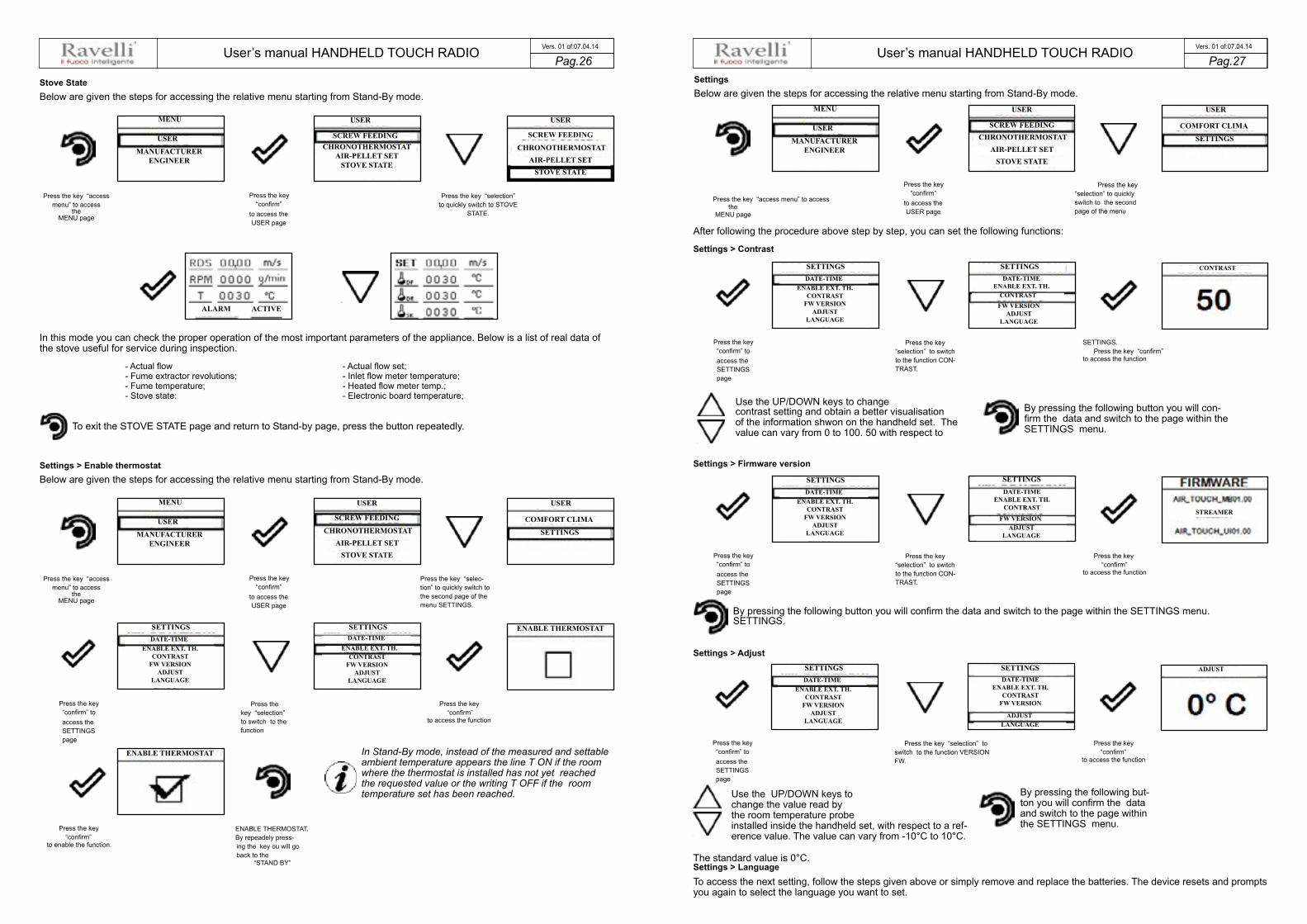
Stove State Below are given the steps for accessing the relative menu starting from Stand-By mode.
Press the key “access menu” to access
the MENU page
Press the key “confirm”
to access the USER page
Press the key “selection” to quickly switch to STOVE
STATE.
In this mode you can check the proper operation of the most important parameters of the appliance. Below is a list of real data of the stove useful for service during inspection.
- Actual flow - Fume extractor revolutions; - Fume temperature; - Stove state:
To exit the STOVE STATE page and return to Stand-by page, press the button repeatedly.
Settings > Enable thermostat Below are given the steps for accessing the relative menu starting from Stand-By mode.
Press the key “access menu” to access
the MENU page
Press the key “confirm” to access the SETTINGS page
Press the key “confirm”
to enable the function.
Press the key “confirm”
to access the USER page
Press the key “selection” to switch to the function
ENABLE THERMOSTAT. By repeadely press-ing the key ou will go back to the
“STAND BY”
- Actual flow set; - Inlet flow meter temperature; - Heated flow meter temp.; - Electronic board temperature;
Press the key “selec-tion” to quickly switch to the second page of the menu SETTINGS.
Press the key “confirm”
to access the function
In Stand-By mode, instead of the measured and settable ambient temperature appears the line T ON if the room where the thermostat is installed has not yet reached the requested value or the writing T OFF if the room temperature set has been reached.
Settings Below are given the steps for accessing the relative menu starting from Stand-By mode.
Press the key “access menu” to access the
MENU page
After following the procedure above step by step, you can set the following functions:
Settings > Contrast
Press the key “confirm” to access the SETTINGS page
Press the key “confirm”
to access the USER page
Press the key “selection” to switch to the function CON-TRAST.
Use the UP/DOWN keys to change contrast setting and obtain a better visualisation of the information shwon on the handheld set. The value can vary from 0 to 100. 50 with respect to
Settings > Firmware version
Press the key “confirm” to access the SETTINGS page
Press the key “selection” to switch to the function CON-TRAST.
By pressing the following button you will confirm the data and switch to the page within the SETTINGS menu. SETTINGS.
Settings > Adjust
Press the key “confirm” to access the SETTINGS page
Press the key “selection” to switch to the function VERSION FW.
Use the UP/DOWN keys to change the value read by the room temperature probe installed inside the handheld set, with respect to a ref-erence value. The value can vary from -10°C to 10°C.
The standard value is 0°C. Settings > Language To access the next setting, follow the steps given above or simply remove and replace the batteries. The device resets and prompts you again to select the language you want to set.
Press the key “selection” to quickly switch to the second page of the menu
SETTINGS. Press the key “confirm”
to access the function
By pressing the following button you will con-firm the data and switch to the page within the SETTINGS menu.
Press the key “confirm”
to access the function
Press the key “confirm”
to access the function
By pressing the following but-ton you will confirm the data and switch to the page within the SETTINGS menu.
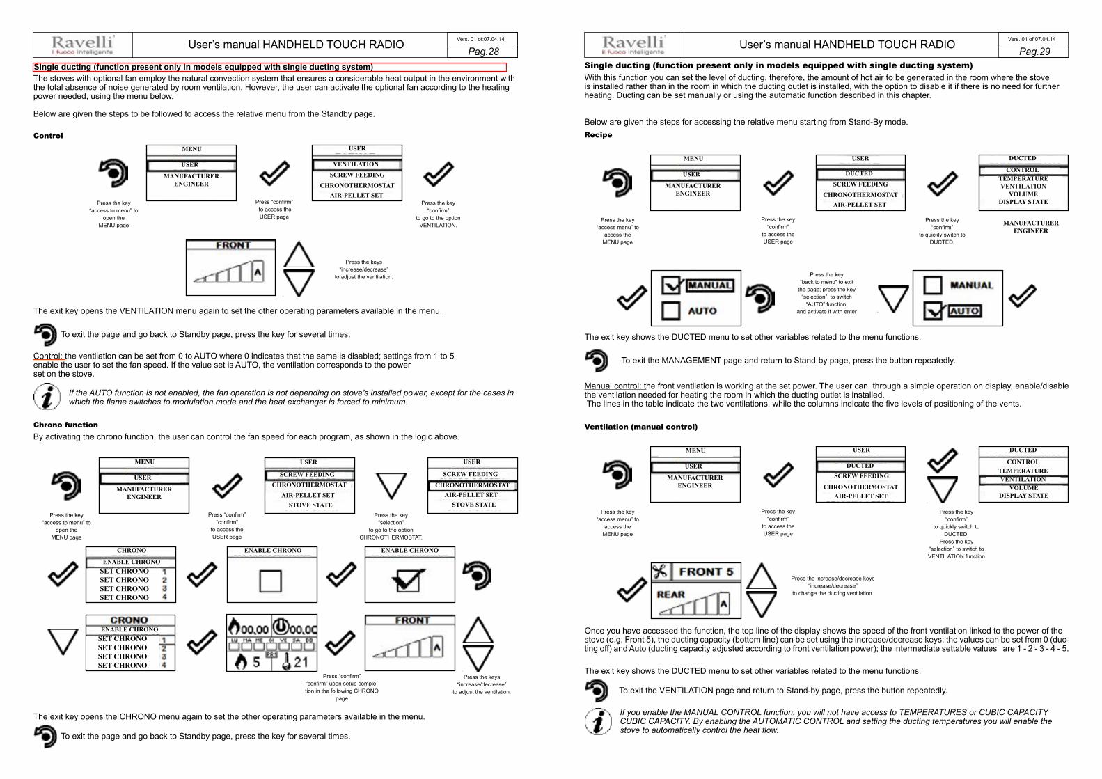
User’s manual HANDHELD TOUCH RADIO User’s manual HANDHELD TOUCH RADIOPag.28 Pag.29 Vers. 01 of:07.04.14 Vers. 01 of:07.04.14
With this function you can set the level of ducting, therefore, the amount of hot air to be generated in the room where the stoveis installed rather than in the room in which the ducting outlet is installed, with the option to disable it if there is no need for further heating. Ducting can be set manually or using the automatic function described in this chapter.
Below are given the steps for accessing the relative menu starting from Stand-By mode.
Press the key“access menu” to
access theMENU page
Press the key“confirm”
to access theUSER page
Press the key“confirm”
to quickly switch toDUCTED.
To exit the MANAGEMENT page and return to Stand-by page, press the button repeatedly.
The exit key shows the DUCTED menu to set other variables related to the menu functions.
Single ducting (function present only in models equipped with single ducting system)
Recipe
Press the key“back to menu” to exit
the page; press the key“selection” to switch
“AUTO” function. and activate it with enter
Manual control: the front ventilation is working at the set power. The user can, through a simple operation on display, enable/disable the ventilation needed for heating the room in which the ducting outlet is installed. The lines in the table indicate the two ventilations, while the columns indicate the five levels of positioning of the vents.
Press the key“access menu” to
access theMENU page
Press the key“confirm”
to access theUSER page
Press the key“confirm”
to quickly switch toDUCTED.
Press the key “selection” to switch toVENTILATION function
Ventilation (manual control)
Press the increase/decrease keys“increase/decrease”
to change the ducting ventilation.
Once you have accessed the function, the top line of the display shows the speed of the front ventilation linked to the power of thestove (e.g. Front 5), the ducting capacity (bottom line) can be set using the increase/decrease keys; the values can be set from 0 (duc-ting off) and Auto (ducting capacity adjusted according to front ventilation power); the intermediate settable values are 1 - 2 - 3 - 4 - 5.
To exit the VENTILATION page and return to Stand-by page, press the button repeatedly.
The exit key shows the DUCTED menu to set other variables related to the menu functions.
If you enable the MANUAL CONTROL function, you will not have access to TEMPERATURES or CUBIC CAPACITY CUBIC CAPACITY. By enabling the AUTOMATIC CONTROL and setting the ducting temperatures you will enable the stove to automatically control the heat flow.
The stoves with optional fan employ the natural convection system that ensures a considerable heat output in the environment with the total absence of noise generated by room ventilation. However, the user can activate the optional fan according to the heating power needed, using the menu below.
Below are given the steps to be followed to access the relative menu from the Standby page.
Press the key“access to menu” to
open theMENU page
Press “confirm” to access theUSER page
Press the key“confirm”
to go to the optionVENTILATION.
To exit the page and go back to Standby page, press the key for several times.
The exit key opens the VENTILATION menu again to set the other operating parameters available in the menu.
Single ducting (function present only in models equipped with single ducting system)
Control
Control: the ventilation can be set from 0 to AUTO where 0 indicates that the same is disabled; settings from 1 to 5 enable the user to set the fan speed. If the value set is AUTO, the ventilation corresponds to the power set on the stove.
If the AUTO function is not enabled, the fan operation is not depending on stove’s installed power, except for the cases in which the flame switches to modulation mode and the heat exchanger is forced to minimum.
Press the keys“increase/decrease”
to adjust the ventilation.
Chrono function By activating the chrono function, the user can control the fan speed for each program, as shown in the logic above.
Press the key“access to menu” to
open theMENU page
Press “confirm”“confirm”
to access theUSER page
Press the key“selection”
to go to the optionCHRONOTHERMOSTAT.
Press the keys“increase/decrease”
to adjust the ventilation.
To exit the page and go back to Standby page, press the key for several times.
The exit key opens the CHRONO menu again to set the other operating parameters available in the menu.
Press “confirm”“confirm” upon setup comple-tion in the following CHRONO
page
USER
USER
DUCTED
DUCTED CONTROL
DUCTED
SCREW FEEDING
SCREW FEEDING
AIR-PELLET SET
AIR-PELLET SET
CHRONOTHERMOSTAT
CHRONOTHERMOSTAT
MENU
MENU
MANUFACTURER ENGINEER
MANUFACTURER ENGINEER
MANUFACTURER ENGINEER
TEMPERATUREVENTILATION
VOLUMEDISPLAY STATE
USER
USER
CONTROLTEMPERATUREVENTILATION
DUCTED
VOLUMEDISPLAY STATE
MENU
MANUFACTURER ENGINEER
USER
USER
VENTILATION
SCREW FEEDING
AIR-PELLET SETCHRONOTHERMOSTAT
MENU
CHRONO
MANUFACTURER ENGINEER
USER
USER USER
SCREW FEEDING SCREW FEEDING
STOVE STATE STOVE STATEAIR-PELLET SET AIR-PELLET SET
CHRONOTHERMOSTAT CHRONOTHERMOSTAT
ENABLE CHRONO
ENABLE CHRONO ENABLE CHRONO
ENABLE CHRONO
SET CHRONO SET CHRONO SET CHRONO SET CHRONO
SET CHRONO SET CHRONO SET CHRONO SET CHRONO
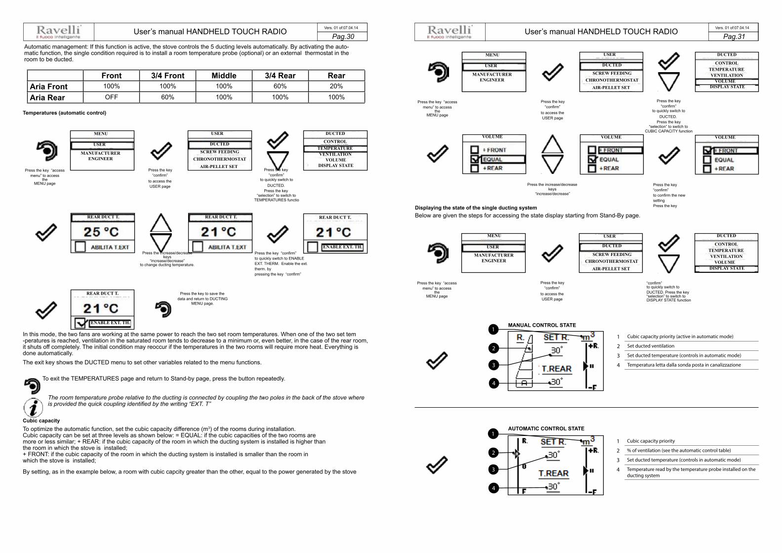
User’s manual HANDHELD TOUCH RADIO User’s manual HANDHELD TOUCH RADIOPag.30 Pag.31 Vers. 01 of:07.04.14 Vers. 01 of:07.04.14
Front 3/4 Front Middle 3/4 Rear RearAria Front 100% 100% 100% 60% 20%
Aria Rear OFF 60% 100% 100% 100%
4
2
11 Cubic capacity priority (active in automatic mode)
2 Set ducted ventilation
3 Set ducted temperature (controls in automatic mode)
4 Temperatura letta dalla sonda posta in canalizzazione3
4
2
11 Cubic capacity priority
2 % of ventilation (see the automatic control table)
3 Set ducted temperature (controls in automatic mode)
4 Temperature read by the temperature probe installed on the ducting system
3
MENU
REAR DUCT T.
REAR DUCT T.
REAR DUCT T. REAR DUCT T.
ENABLE EXT. TH.
ENABLE EXT. TH.
MANUFACTURER ENGINEER
USER
USER
SCREW FEEDING
DUCTED
AIR-PELLET SETCHRONOTHERMOSTAT
VENTILATION
DUCTED
VOLUMEDISPLAY STATE
CONTROLTEMPERATURE
MENU
MANUFACTURER ENGINEER
USER
USER
USER
SCREW FEEDING
SCREW FEEDING
DUCTED
DUCTED
AIR-PELLET SET
AIR-PELLET SET
CHRONOTHERMOSTAT
CHRONOTHERMOSTAT
VENTILATION
VENTILATION
VOLUME
VOLUME
VOLUME VOLUME VOLUME
DUCTED
DUCTED
DISPLAY STATE
DISPLAY STATE
CONTROL
CONTROL
TEMPERATURE
TEMPERATURE
MENU
MANUFACTURER ENGINEER
USER
Automatic management: If this function is active, the stove controls the 5 ducting levels automatically. By activating the auto-matic function, the single condition required is to install a room temperature probe (optional) or an external thermostat in the room to be ducted.
Temperatures (automatic control)
Press the key “access menu” to access
the MENU page
Press the key “confirm”
to access the USER page
Press the increase/decrease keys
“increase/decrease” to change ducting temperature.
Press the key to save the data and return to DUCTING
MENU page.
Press the key “confirm”
to quickly switch to DUCTED.
Press the key “selection” to switch to
TEMPERATURES functio
Press the key “confirm” to quickly switch to ENABLE EXT. THERM. Enable the ext. therm. by pressing the key “confirm”
In this mode, the two fans are working at the same power to reach the two set room temperatures. When one of the two set tem -peratures is reached, ventilation in the saturated room tends to decrease to a minimum or, even better, in the case of the rear room, it shuts off completely. The initial condition may reoccur if the temperatures in the two rooms will require more heat. Everything is done automatically. The exit key shows the DUCTED menu to set other variables related to the menu functions.
To exit the TEMPERATURES page and return to Stand-by page, press the button repeatedly.
The room temperature probe relative to the ducting is connected by coupling the two poles in the back of the stove where is provided the quick coupling identified by the writing “EXT. T”
Cubic capacity To optimize the automatic function, set the cubic capacity difference (m3) of the rooms during installation. Cubic capacity can be set at three levels as shown below: = EQUAL: if the cubic capacities of the two rooms are more or less similar; + REAR: if the cubic capacity of the room in which the ducting system is installed is higher than the room in which the stove is installed; + FRONT: if the cubic capacity of the room in which the ducting system is installed is smaller than the room in which the stove is installed;
By setting, as in the example below, a room with cubic capcity greater than the other, equal to the power generated by the stove
MANUAL CONTROL STATE
Press the key “access menu” to access
the MENU page
Press the key “confirm”
to access the USER page
Press the increase/decrease keys
“increase/decrease”
Displaying the state of the single ducting system Below are given the steps for accessing the state display starting from Stand-By page.
Press the key “access menu” to access
the MENU page
Press the key “confirm”
to access the USER page
AUTOMATIC CONTROL STATE
Press the key “confirm”
to quickly switch to DUCTED.
Press the key “selection” to switch to
CUBIC CAPACITY function
Press the key “confirm” to confirm the new setting Press the key
“confirm” to quickly switch to DUCTED. Press the key “selection” to switch to DISPLAY STATE function

User’s manual HANDHELD TOUCH RADIO User’s manual HANDHELD TOUCH RADIOPag.32 Pag.33 Vers. 01 of:07.04.14 Vers. 01 of:07.04.14
Rear Left(posteriore sx)
Rear Left/Middle(posteriore sx/centro) Middle Middle/Rear right
(centro/posteriore dx)Rear Right(posteriore dx)
Aria frontale da OFF ad A da OFF ad A da OFF ad A da OFF ad A da OFF ad AAria posteriore dx 15% 40% 65% 85% 100%Aria posteriore sx 100% 85% 65% 40% 15%
Ventilazione (gestione manuale)
Oppure
Oppure
Press the increase/decrease keys
“increase/decrease” to change the front ventilation.
Press “confirm” to switch to ducting setup.
ducting.
Double ducting (function present only in models equipped with double ducting system) The range of stoves that use the following control system, dedicates much of its performance to ducting. This is shown by the fact that the front fan is small and can be set by the customer independently from the management of both manual and automatic duct -ing, as well as the operating power of the stove. With regard to ducting control, this feature allows you to set the ducting level, therefore the amount of hot air to be developed in a room rather than another.
Below are given the steps for accessing the relative menu starting from Stand-By mode.
Recipe
Press the key “access menu” to access
the MENU page
Press the key “confirm”
to access the USER page
Press the key “back to menu” to exit the page; press the selection key to switch to “AUTO” function and activate it with “V”
Press the key “confirm”
to quickly switch to MANAGEMENT.
The exit key shows the DUCTED menu to set other variables related to the menu functions.
To exit the MANAGEMENT page and return to Stand-by page, press the button repeatedly.
Manual management: the user can set, through a simple operation on the display, the percentage of hot air to be dedicated to heat-ing both rooms to be ducted. The front ventilation can be set separately from ducting management. Below is described the proce-dure for settingthe ventilation according to user’s requirements.
Ventilation (manual control)
Press the key “access menu” to access
the MENU page
Press the key “confirm”
to access the USER page
Press the key “confirm”
to quickly switch to VENTILATION.
Press the increase/decrease keys
“increase/decrease” to change ducting position.
Or
Direct switch in case you do not intend to enable the external
Enable the ext. therm. by pressing the key “confirm”
Or
Direct switch in case you do not intend to enable the external
Once you accessed the function, the top line of the display shows the speed of the front ventilation which can be set by means of “increase / decrease” keys with values that can be set from 0 (ducting off) to Auto (ducting capacity that follows the power of the front ventilation); intermediate values can be set from 1-2 - 3 - 4 - 5. Regarding the ducting system, you can manually set the amount of heat that you want to be directed towards the vents. The exit key shows the DUCTED menu to set other variables related to the menu functions.
To exit the VENTILATION page and return to Stand-by page, press the button repeatedly.
If you enable the MANUAL CONTROL function, you will not have access to TEMPERATURES or CUBIC CAPACITY CUBIC CAPACITY. By enabling the AUTOMATIC CONTROL and setting the ducting temperatures you will enable the stove to automatically control the heat flow.
Automatic management: If this function is active, the stove controls the 5 ducting levels automatically . It should be noted that, by enabling the automatic function, it is required to install two room temperature probes (optional) or external thermostats Temperatures (automatic control)
Press the key “access menu” to access
the MENU page
Press the key “confirm”
to quickly switch to ENABLE EXT. THERM.
Press the key “confirm”
to access the USER page
Press the increase/decrease keys
“increase/decrease” to change ducting tempera-
ture.
Press the key “confirm”
to enable the control with external thermostat
Press the key “confirm”
to quickly switch to TEMPERATURES.
Press the key “confirm”
to quickly switch to ENABLE EXT. THERM.
Press the increase/decrease keys
“increase/decrease” to change ducting temperature
Press the key to save the data and return to DUCTING
MENU page
MENU
MANUFACTURER ENGINEER
USER
USER
DUCTING
DUCTING
CONTROLTEMPERATUREVENTILATION
CUBIC CAPACITYDISPLAY STATE
SCREW LOADINGCHONOTHERMOSTAT
SET AIR-PELLET
MENU
MANUFACTURER ENGINEER
USER
USER DUCTING
DUCTING
SCREW LOADING
CONTROL
CHONOTHERMOSTAT
TEMPERATURE
SET AIR-PELLET
VENTILATIONCUBIC CAPACITYDISPLAY STATE
MENU
MANUFACTURER ENGINEER
USER
USER
DUCTING
SCREW LOADINGCHONOTHERMOSTAT
SET AIR-PELLET
DUCTING
CONTROLTEMPERATUREVENTILATION
CUBIC CAPACITYDISPLAY STATE
DUCTING
CONTROLTEMPERATUREVENTILATION
CUBIC CAPACITYDISPLAY STATE

User’s manual HANDHELD TOUCH RADIO User’s manual HANDHELD TOUCH RADIOPag.34 Pag.35 Vers. 01 of:07.04.14 Vers. 01 of:07.04.14
6
3
11 Temperature read by the temperature probe installed on the
(RH) ducting system
2 Set RH ducted temperature (controls in automatic mode)
3 Set LH ducted temperature (controls in automatic mode)
4 Temperature read by the temperature probe installed on the (LH) ducting system
5 % of ventilation (see the MAN and AUT control table)
6 Cubic capacity priority among rooms (active in automatic mode)
4
STATE IN MANUAL CONTROL
STATE IN MANUAL CONTROL
5
2
1 Temperature read by the temperature probe installed on the(RH) ducting system
2 Set RH ducting temperature
3 Set LH ducting temperature
4 Temperature read by the temperature probe installed on the(LH) ducting system
5 % of ventilation (see the MAN and AUT control table)
6 Cubic capacity priority among rooms
Stove phase synthetical layout
PHASE DESCRIPTION
FINAL CLEANING
The stove is in the switch off phase and the cooling phase has not been completed yet.
SWITCH ON The heater pre-heating phase has started and the pellets start to fall into the grate.
WAITING FOR FLAME The pellets ignite and take advantage of the heat in the intake air that passes through theincandescent heater tube.
FLAME PRESENT The flame is visible in the grate.
AREAS
The stove has completed the switch on phase and runs at maximum set capacity.
WORK MODULA
The room temperature set has been reached.
THE GRATE Brazier cleaning phase is active (periodic function).
ECO STOP With Climate Comfort active, the stove switches to automatic switch-off mode whenthe room temperature set is reached (see the dedicated section).
6
3
1
4
5
2
In this mode, the two fans are working at the same power to reach the two set room temperatures. When one of the set tempera -tures is reached, the ventilation in the saturated room tends to decrease to a minimum, increasing the ventilation of the room in which temperature still needs to be increased. The initial condition may reoccur if the temperatures in the two rooms will require more heat. Everything is done automatically. The exit key shows the DUCTED menu to set other variables related to the menu functions.
To exit the TEMPERATURES page and return to Stand-by page, press the button repeatedly.
The room temperature probe relative to the ducting is connected by coupling the two poles in the back of the stove where is provided the quick coupling identified by the writing “EXT. T” and “T.EXT R.R.”
Cubic capacity To optimize the automatic function, set the cubic capacity difference (m3) of the rooms during installation. Cubic capacity can be set at three levels as shown below: = EQUAL: if the cubic capacities of the two rooms are more or less simi-lar; + REAR RIGHT: if the cubic capacity of the room where the RH ducting system is installed is greater than the LH ducting system (referred to the stove in the front view); + REAR LEFT: if the cubic capacity of the room where the LH ducting system is installed is greater than the RH ducting system (referred to the stove in the front view);
By setting, as in the example below, a room with cubic capcity greater than the other, equal to the power generated by the stove and the ambient temperature lower than the set temperature on both outlets, the heat input will be mainly directed towards the larger room.
Press the key “access menu” to access
the MENU page
Press the key “confirm”
to access the USER page
Press the increase/decrease keys
“increase/decrease”
Displaying the state of the double ducting system Below are given the steps for accessing the state display starting from Stand-By page.
Press the key “access menu” to access
the MENU page
Press the key “confirm”
to access the USER page
Press the key “confirm”
to quickly switch to CUBIC CAPACITY.
Press the key “confirm”
to confirm the new setting
Press the key “confirm”
to quickly switch to DUCTED.
Press the key “selection” to switch to
DISPLAY STATE function
MENU
MANUFACTURER ENGINEER
USER
CUBIC CAPACITY CUBIC CAPACITY CUBIC CAPACITY
USER
DUCTING
DUCTING
CONTROLTEMPERATUREVENTILATION
CUBIC CAPACITYDISPLAY STATE
SCREW LOADINGCHONOTHERMOSTAT
SET AIR-PELLET
MENU
MANUFACTURER ENGINEER
USER
USER
DUCTING
DUCTING
CONTROLTEMPERATUREVENTILATION
CUBIC CAPACITYDISPLAY STATE
SCREW LOADINGCHONOTHERMOSTAT
SET AIR-PELLET

User’s manual HANDHELD TOUCH RADIO User’s manual HANDHELD TOUCH RADIOPag.36 Pag.37 Vers. 01 of:07.04.14 Vers. 01 of:07.04.14
FLAME DESCRIPTION
RDS SYSTEM ADJUSTMENTREQUEST
(only if the RDS system is provi-ded)
It shows that the testing procedure and initial parameter calibration have not been comple-ted or have been performed incorrectly. This indication, however, does not block the stove.
SERVICE REQUEST The threshold value of set work hours has been reached. The symbol displayed remainsactive throughout the work phase. Non-routine maintenance is required on the stove.
AIR FLOW METER FAILU-RE
(only if the RDS system is provi-ded)
It shows a failure of the air flow meter and the stove switches to minimum capacity disablingthe RDS system.
Warning Pop-Up
PHASE DESCRIPTION
START/RESTART WAIT Switch-on is requested but with the stove in cooling phase; once this condition is met, itrestarts automatically.
SWITCH ON RESTART The HOT restart phase is activated.Functioning is similar to the SWITCH ON phase
HOT SMOKE
The maximum fume temperature threshold has been reached. To facilitate cooling, thestove brings the capacity to a minimum with ventilation at power level 5, leading to a decre-asein fume temperature.
OFF The stove is off
WAIT FOR PELLETSOUT OF
When the switch-on request from ECO-STOP mode coincides with anautomatic switch-off condition (from the TIMER), the stove turns on ensuring total cleaningof the brazier before switching to FINAL CLEANING.
INFEED SCREWOVERFLOW
CONDITION: when the pellet setting (set pellets +5) is near the continuous load condition.SOLUTION: Set the value back to 0.
GENERIC ALARM The stove is in alarm state; refer to the throubleshooting chapter.
ANOMALY (general) The stove has detected an anomaly; refer to the throubleshooting chapter.
AUTOMATIC CLEANING SYSTEMACTIVE
For models with semiautomatic cleaning it indicates the state of the same.
REASON SOLUTION• The door and the ash box are not closed correctly • Make sure they are properly closed.
• Poor combustion in grate. • Switch off the stove, clean the brazier and check the cleanliness of thesupport bench, clean the tube bundle by activating the turbolators. andadjust the combustion through Pellet/Air settings.• Presence of foreign body in air intake tube. • Check for any foreign body and remove it• The air flow meter may be dirty. • Clean the flow meter with the stove in "Switched off" state
• Contact the Support Service
SIGNALLING
RUNBRAZIER CLEANING
(only if the RDS system is provided)
The appearance of the message “ADJUST THE RDS SYSTEM” indicates that the initial parameter testing procedure andcalibration has been unsuccessfully. This indication does not block the stove.
Alarms (table with reference codes)
TRIAL TITLE REASON SOLUTION
AL 01 BLACK OUT
- No voltage during work phase - Press the switch off key and switch onboiler switch-on.
- If the problem persists, contact the SupportService
AL 02 FUME PROBE- The fume probe is malfunctioning - Contact the Support Service
- The fume probe is disconnected from the electro-nic board
- Contact the Support Service
AL 03 FUME OVERTEMP.
- Combustion in the brazier is not optimal due toclogging or obstructions of internal stove ducts
- Switch off the stove, clean the brazier and thetube bundle and adjust the combustion setting the Pellet/Air values
- The tangential fan (if provided) ismalfunctioning or damaged
- Contact the Support Service
- If the problem persists, contact the SupportService
AL 04 FUME EXHAUST DAMAGED
- Fume exhaust encoder is not working or isconnected incorrectly
- Contact the Support Service
- No power to fume exhaust system - Contact the Support Service
- The fume exhaust system is blocked - Contact the Support Service
AL 05 NO SWITCH-ON
- The pellet tank is empty - Check for the presence of pellets in the contai-ner. Top up, if necessary.
- Pellet calibration and suction during switch onphase is incorrect.
- Contact the Support Service
- The igntition coil is faulty or positioned - Contact the Support Service
AL 06 PELLETS FINISHED
- The pellet tank is empty. - Check for the presence of pellets in the contai-ner. Top up, if necessary.
- The gear motor is not loading pellets - Empty the tank to see if there are any objects inside that may prevent the proper operation of the auger.
- Not enough pellets loaded - Regulate pellets setting from “SET AIR/PEL-LETS”
- If the problem persists, contact the SupportService Support
AL 07 RESET THERMAL BREAKER / PELLET DOOR OR GATE OPEN
- The manual reset thermostat has tripped connected to the hopper (RESET THERMAL BREAKER / Pellet door or gate is open
- Reset the thermostat by pressing the button on the back of the stove or close the doors.
- Combustion in the grate is not optimal due to the fact that the grate is clogged or the inner stove ducts are clogged. (RESET THERMAL BREAKER)
- Switch off the stove, clean the brazier and thetube bundle and adjust the combustion setting the Pellet/Air values
- Contact the Support Service
AL 08 DEPRESSURIZATION- The flue is blocked. Check the flue is free and clean
- The vacuum meter is faulty. - Contact the Support Service
AL 12 FUME EXHAUST SYSTEMFAILURE
- T he fume exhaust system has a loss of perfor-mance due to fan obstruction or voltage drop.
- Contact the Support Service
AL 14 SCREW PHASE - No cable connection to power the gear motorof the auger
- Contact the Support Service
AL 15 AUGER TRIAC
- An internal part of the electronic board that controls the pellet infeed screw is faulty.
- Contact the Support Service
- Possible voltage drops or incorrect input voltage stove inlet
- Check the mains voltage.
AL 17 NO FLOW(only if the RDS system is provided)
- The flow meter does not measure inlet air flow - Check if the ash pan and door are closed correctly and check if the air inlet pipe is obstructed.
- If the problem persists, contact the Support Service
AL 19 CLEANER FAILURE(for models equipped with cleaner)
- The cleaner did not complete the movement and is not in the correct position
- Reset the alarm and wait for the stoveto switch to SHUTDOWN mode. Cut off and power again, the system reactivates the cleaner trying to search the correct position again.
-- If the problem persists, contact the Support Service
Excessive Load
Adjust RDS system
modulate

User’s manual HANDHELD TOUCH RADIO User’s manual HANDHELD TOUCH RADIOPag.38 Pag.39 Vers. 01 of:07.04.14 Vers. 01 of:07.04.14
Unscrew the protective cap and pressthe button to reset the thermal breaker
PLEASE READ CAREFULLY THE FOLLOWING INSTRUCTIONS TO PERFORM PROPER CLEANING. FAILURE TO COMPLY WITH THESE INSTRUCTIONS MAY LEAD TO MALFUNCTIONS OF THE STOVE.
Grate
Grate grid
Housing
In the case of alarm 07 THERMAL BREAKER below shows the location where to operate to reset the thermal switch with manual reset.
Cleaning should be provided by the user Before any cleaning operation on the stove, implement the following precautions:
- switch off the stove and disconnect the power cord with the stove in “Switched OFF” state; - make sure all the parts of the stove are cold; - make sure the ash is completely cooled.
Unscrew the protective cap and press the button to reset the thermal breaker
Manual reset thermal breaker
Clean the surfaces To clean the surfaces of the coated metal parts, use a cloth soaked in water or water and soap. Attention! Use of abrasive detergents or diluents can damage the surface of the stove.
Grate cleaning should be carried out before each switch on To ensure proper cleaning before switching on the stove, it is necessary to check that the brazier is clean and so that they are always excellent combustion, thus avoiding any overheating that may cause changes in the color of the paint or peeling of the door coating. Furthermore, poor cleaning of the grate can cause stove switch on problems.
Before removing the grate and check for any dirt inside it, remember to remove the “grill grate”. Once the brazier grill is clean it should be fitted in its housing ALWAYS AFTER having installed the brazier.
Clean basket
Basket that needs cleaning
If you use another type of pellets, even of the same brand, this may lead to differences in combustion that may result in greater ash de-posits inside the grate. Correct cleaning, carried out on a daily basis, allows the stove to burn pellets omptimally with a good and steady heating output, preventing malfunctions that over time may call for the intervention of a technician to restore stove’s operation.
Cleaning the ash pan Remove the drawer from the stove and remove the ash collected using an ash vacuum; be very careful if the grate is still hot as this can damage the cleaning equipment.
Cleaning operations of the stove depend on the quality of the pellets used and the frequency of use. It may be necessary to carry out these operations on a daily basis.
Drawer ash
DO NOT SWITCH ON THE STOVE IF YOU NOTICE ANY DAMAGES ON GLASS SURFACE. CONTACT THE TECHNICAL SUPPORT SERVICE TO HAVE IT REPLACED.
Manual tube bundle cleaning (where applicable)
Operate the L-shaped pin forward and backward to keep the tube bundle clean and thus ensure optimal heat exchange.
Cleaning the internal vermiculite (Firex 600)
Pin to be operated “Forward/Backward”
Ash pan that needs to be emptied
Cleaning glass The glass of the door should be cleaned with the stove cooled down using a cotton cloth or paper towel. Usually, we recommend you clean the glass with a damp (water) cloth and ash collected after burning (having an abrasive function).
The FIREX 600 products stand out due to the fact that they are heat resistant, lightweight and have excellent insulation capacity, with consequent improvement of combustion and performance of the stove. During combustion, the FIREX 600 whitens due to Pyrolysis, mak-ing the flame light and bright. Therefore, if combustion is suitably regu-lated, the original colour of the internal part of FIREX 600 remains unchanged.
This means that the colour of vermiculite during combustion indicates whether the latter is correct or not: FIREX 600 LIGHT = OPTIMAL COMBUSTION FIREX 600 DARK = BAD COMBUSTION
Firex 600 does not require any specific maintenance. you must only remove the dust with a brush if you intend to clean the ash built up during combustion. - You should not use abrasive sponges to clean the more stubborn residues as it could compromise the thickness of the FIREX 600, creating critical breaking points. - It is not advisable to use the vacuum cleaner hose in direct contact with FIREX 600. - It is not advisable to use damp clothes to clean the FIREX 600.
FIREX 600 is resistant to heat but not to shocks: handle it carefully after removal. After a few hours of operation FIREX 600 may show slight abrasion: this is absolutely normal, as the flame creates micro-grooves in the panel, without compromising the latter. The service life of FIREX 600 depends exclusively on the way in which maintenance is performed.
Pellet door/gate open
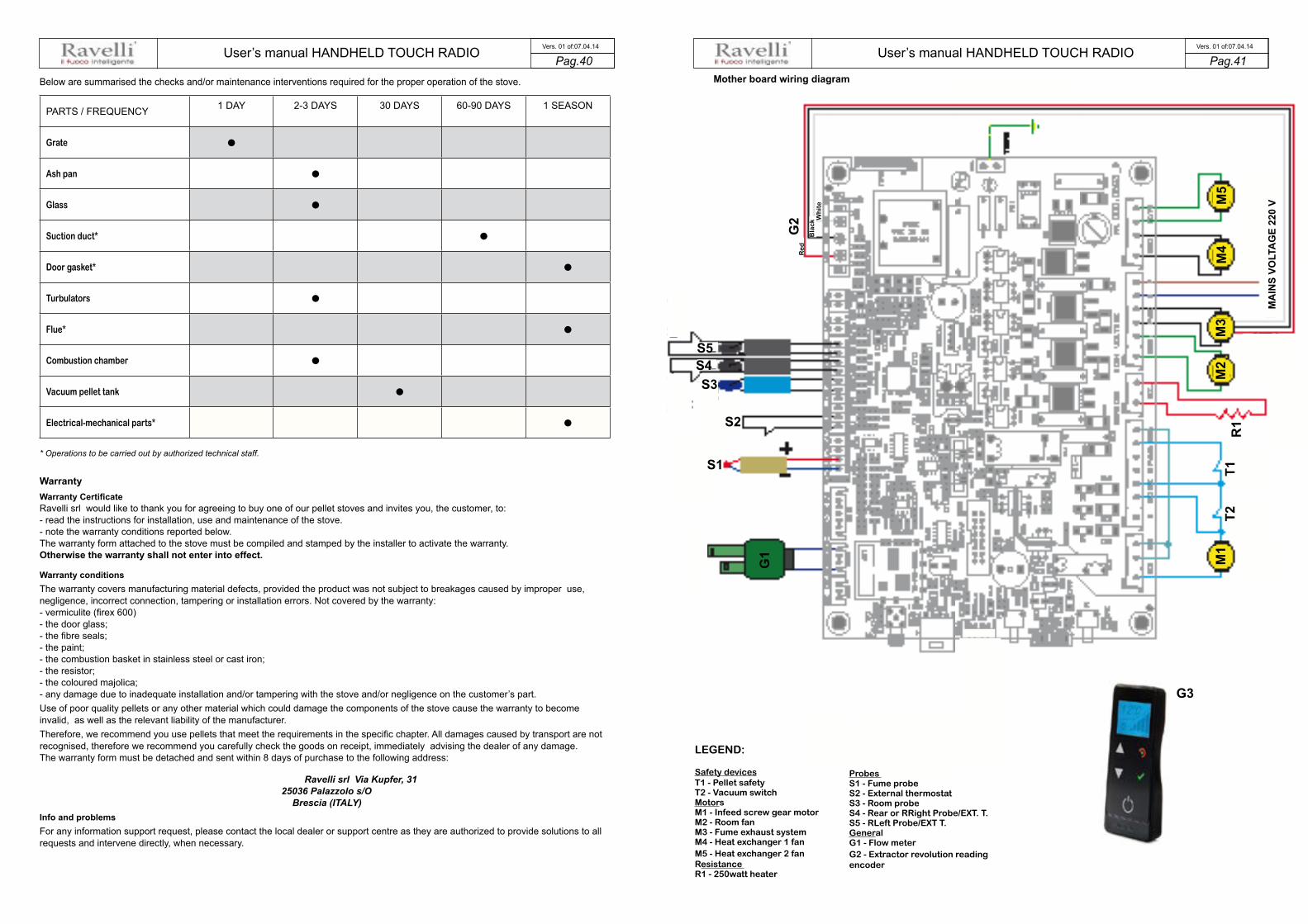
User’s manual HANDHELD TOUCH RADIO User’s manual HANDHELD TOUCH RADIOPag.40 Pag.41 Vers. 01 of:07.04.14 Vers. 01 of:07.04.14
PARTS / FREQUENCY 1 DAY 2-3 DAYS 30 DAYS 60-90 DAYS 1 SEASON
Grate •Ash pan •Glass •Suction duct* •Door gasket* •Turbulators •Flue* •Combustion chamber •Vacuum pellet tank •Electrical-mechanical parts* •
Below are summarised the checks and/or maintenance interventions required for the proper operation of the stove.
M1
M2
M3
M4
M5
S1
R1S2
G1
G2
G3
Bla
ck
Re
d
Wh
ite
T2T1
S3S4S5
* Operations to be carried out by authorized technical staff.
Warranty Warranty Certificate Ravelli srl would like to thank you for agreeing to buy one of our pellet stoves and invites you, the customer, to: - read the instructions for installation, use and maintenance of the stove. - note the warranty conditions reported below. The warranty form attached to the stove must be compiled and stamped by the installer to activate the warranty. Otherwise the warranty shall not enter into effect.
Warranty conditions The warranty covers manufacturing material defects, provided the product was not subject to breakages caused by improper use, negligence, incorrect connection, tampering or installation errors. Not covered by the warranty: - vermiculite (firex 600) - the door glass; - the fibre seals; - the paint; - the combustion basket in stainless steel or cast iron; - the resistor; - the coloured majolica; - any damage due to inadequate installation and/or tampering with the stove and/or negligence on the customer’s part. Use of poor quality pellets or any other material which could damage the components of the stove cause the warranty to become invalid, as well as the relevant liability of the manufacturer. Therefore, we recommend you use pellets that meet the requirements in the specific chapter. All damages caused by transport are not recognised, therefore we recommend you carefully check the goods on receipt, immediately advising the dealer of any damage. The warranty form must be detached and sent within 8 days of purchase to the following address:
Ravelli srl Via Kupfer, 31 25036 Palazzolo s/O
Brescia (ITALY) Info and problems For any information support request, please contact the local dealer or support centre as they are authorized to provide solutions to all requests and intervene directly, when necessary.
Mother board wiring diagram
MA
INS
VOLT
AG
E 22
0 V
LEGEND:
Safety devices T1 - Pellet safety T2 - Vacuum switch Motors M1 - Infeed screw gear motor M2 - Room fan M3 - Fume exhaust system M4 - Heat exchanger 1 fan M5 - Heat exchanger 2 fan Resistance R1 - 250watt heater
Probes S1 - Fume probe S2 - External thermostat S3 - Room probe S4 - Rear or RRight Probe/EXT. T. S5 - RLeft Probe/EXT T. General G1 - Flow meter G2 - Extractor revolution reading encoder

User’s manual HANDHELD TOUCH RADIO User’s manual HANDHELD TOUCH RADIOPag.42 Pag.43 Vers. 01 of:07.04.14 Vers. 01 of:07.04.14
M2
M3
S1
R1S2
G1
G2
G3
Bla
ck
Re
d
Wh
ite
T2T1
Mother board wiring diagram (mod. BLOW)
S3
M1
G4
T3
LEGEND:
SafetyT1- Fire Door contactT2- Pellet tank contactT3 - Pallet safety deviceT4 - Vacuum switch
MotorsM1 - Feed screw gear motorM2 - Automatic cleaning systemM3 - Smoke exhaust systemM4 - Heat exchanger (natural con vection or optional fan ventilated stoves)M5 - RH heat exchanger (stoves with double ducting)M6 - RH or LH heat exchanger (stoves with single ducting or double ducting)
HeaterR1 - Heater ProbesS1 - Flame probe (K)S2 - External thermostatS3 - Room probe (opt)GeneralG1 - Flow meterG2 - Extractor revolution reading encoderG3 - Handheld set “RADIO” TouchG4 - Mechanical cleaner counterG5 - Home automation control contactG6 - GAS switch-on contact- Home automation output alarm (TRF 39)
SC
HE
MA
CO
NN
ES
SIO
NI
O0
83
_1
vers
ion
e «
soffi
o»
RE
V 1
.0
DE
PT
ER
MS
IC
CA
ND
EL
ET
TA
RE
TE
23
0V
AC
VENTILATORE FUMI
MO
TO
RE
CO
CL
EA
DE
BIM
ET
RO
SO
ND
A
FU
MI
T
CK
TE
RM
AM
B S
ON
DA
AM
BIE
NT
E N
TC
10
K
F
INE
C
OR
SA
PU
LIT
OR
E
PA
LM
AR
E
RA
DIO
PP
UL
ITO
RE
M2
M3
S1
R1S2
G1
G3
Bla
ck
Re
d
wh
ite
T1
Mother board wiring diagram (models 2015)
MA
INS
VOLT
AG
E 22
0 V
S3
G4
T3
G5
G2
OPTIONAL boardfor home
automation control
N COM
NC NO
G6
G2
NCG6
NOG6
CG6 G5 G5
10 9 8 7 6 5 4 3 2 1
OPTIONAL connection for home automation control
Neutral
M4
M5
M6
Phase
M1
T4
T2
MA
INS
VOLT
AG
E 22
0 V
LEGEND:
Safety devices T1 - Pellet safety T2 - Vacuum switch Motors M1 - Infeed screw gear motor M2 - Room fan M3 - Fume exhaust system M4 - Heat exchanger 1 fan M5 - Heat exchanger 2 fan Resistance R1 - 250watt heater
Probes S1 - Fume probe S2 - External thermostat S3 - Room probe S4 - Rear or RRight Probe/EXT. T. S5 - RLeft Probe/EXT T. General G1 - Flow meter G2 - Extractor revolution reading encoder

User’s manual HANDHELD TOUCH RADIO Pag.44 Vers. 01 of:07.04.14
DATE INTERVENTION CARRIED OUT
MAINTENANCEGas boiler contact (Optional)
The stoves belonging to range 2015 feature (optional) a contact that switches on the gas boiler if the stove goes in alarm state.
• The output must be connected to the terminal on the stove – G6 (on the relay NC contact)
•The output behaves as follows: when the stove passes in alarm state, the control deactivates the relay on the NC contact to which should be connected the gas boiler switch-on contact. Contact that is activated as soon as the stove goes to switch-on state.
Home automation (Optional)
The stoves belonging to range 2015 feature (Optional) a control for one contact at the input of the board and an output that signals the STOVE STATUS in order to interface the product with an evolved home automation system. Here is description of the operation of the home automation system that allows you to interface it with programmable home automation systems.
• The input must be connected to the terminal on the stove – G5
• The output must be connected to the terminal on the stove – G6 (on the relay NO contact)
• To switch on the stove, send a pulse of at least 1 sec at the input G5 (contact closure for at least 1 s); there must be a pause of at least 1s between one pulse and the other.
• The output behaves as follows: upon every switch-on, it turn on for 2 sec, upon each shutdown, it turns on for 4sec, in alarm it remains on (between one activation and the next is a pause of 1 s; for example, if the system is switched on and then turned off immediately, the output will behave as follows: ON for 2s / OFF for 1s / ON for 4s).
• If there is an alarm, the home automation system cannot reset it (to reset the alarm please refer to ALARMS section.

DATE INTERVENTION CARRIED OUT
MAINTENANCEDATE INTERVENTION CARRIED OUT
MAINTENANCE

Ravelli srl is not liable for any errors in this booklet and is free to make changes to thefeatures of its products without prior warning.
Ravelli srlVia Kupfer, 31 - 25036 Palazzolo sull’Oglio / BS - ITALYTel. +39.030.7402939Fax. +39.030.7301758Internet : www.ravelligroup.itE-mail : [email protected]