use of coatings to reduce fluorine compound · pdf fileuse of coatings to reduce fluorine...
TRANSCRIPT

CASTELLÓN (ESPAÑA)
www.qualicer.org 1
USE OF COATINGS TO REDUCE FLUORINE COMPOUND EMISSIONS
J. Piquer (1); M. Pintor (2); M. Catalán (3); A. Figols (4); E. Monfort (5); F. J. García-Ten (5); C. Moreda (5); S. Gomar (5)
(1) Neos Additives, S.L. Onda. Spain(2) Azuliber 1, S.L. L’Alcora. Spain
(3) Maincer, S.L. Onda. Spain(4) Cerámica Vilar Álbaro, S.L. L’Alcora. Spain
(5) Instituto de Tecnología Cerámica (ITC). Asociación de Investigación de las Industrias Cerámicas (AICE). Universitat Jaume I. Castellón. Spain
ABSTRACT
One of the environmental problems in the firing stage in ceramics manufacture is the emission into the atmosphere of fluorine compounds, regarding which numerous studies have been conducted. In most countries, emission limit values have been established that often require the implementation of corrective measurements to assure compliance. In the European Union, the limit values set for companies are of the order of 5–10 mg/Nm3. Fluorine compound emissions in the firing stage of Spanish ceramic tile manufacturers range between 5 and 55 mg/Nm3, making it necessary to adopt corrective measures, the most common being the use of baghouses with an adsorbent or fixed-bed adsorption.
CASTELLÓN (ESPAÑA)
www.qualicer.org 2
In this study, an alternative system is proposed for correcting fluorine compound emissions. The system consists of coating the tile bottom surface with a composition that is able to retain the fluorine compounds that are released and to integrate them into the tile. A treatment system is therefore not required, and no waste is produced.
Several coating compositions were designed and optimised on a laboratory scale. Industrial trials were then conducted with different types of tiles (different porosity, peak temperature, thickness, etc.) to evaluate the efficiency, as well as the technical and economic feasibility, of the proposed system. Finally, an application system was developed that enables the bottom surface of the tile to be continuously coated in a controlled form.
The results obtained in the industrial trials verified the effectiveness of the coating: reduction efficiencies in fluorine compound emissions were achieved that ranged from 40 to 60% as a function of tile characteristics. The system is, therefore, deemed a feasible alternative for correcting such emissions.
1. INTRODUCTION
1.1. ISSUES TO BE ADDRESSED
The main environmental impact associated with the firing of ceramic products is gas emissions into the atmosphere. Such emissions can contain particulate matter and gaseous pollutants of an acid nature in the form of fluorine, chlorine, and sulphur compounds. [1]
Owing to the environmental impact produced by this type of activity, ceramics manufacturing is including in Annex I of Directive 2010/75/EU on industrial emissions (integrated pollution prevention and control), also known as the IED. The application of this Directive requires compliance with certain emission limit values (ELV) as a function of the type of air pollutant. The ELV are fixed in accordance with the Commission Implementing Decision establishing the best available techniques (BAT) conclusions for the industries affected by the IED. These values are known as the BAT-associated emission limit values (ELV-BAT).

CASTELLÓN (ESPAÑA)
www.qualicer.org 3
The ELV-BAT values defined in the ceramic BREF document for the firing stage in ceramic tile manufacture are detailed in Table 1.
Document HF HCl SO2 NOx (como NO2)
BREF (ELV-BAT) 5 30 500 250
Table 1. Emission values in the ceramic tile firing stage according to the ceramic BREF (mg/Nm3 at 18% O2 and dry gas).
mg/Nm3: concentration in normal temperature (273 K) and pressure (101,3 kPa) conditions.
Figure 1 presents a comparison of HF emission levels as a function of the type of ceramic tile made and the colour of the body, corresponding to the firing kilns, displayed as a median (50th percentile), and the applicable ELV-BAT.
Figure 1. Levels of fluorine compound emission in the firing kilns and comparison with the ELV-BAT where AR: red-body earthenware tile, AB: white-body earthenware tile, GR: red-body stoneware tile,
GB: white-body stoneware tile.
The comparison in Figure 1 shows that the HF emissions need to be corrected by adopting appropriate cleaning systems before emission into the air. However, in the case of the white-body earthenware tile, each case needs to be studied individually because the emission is significantly lower than that recorded for the other products and may be below the ELV-BAT without any cleaning systems being required.

CASTELLÓN (ESPAÑA)
www.qualicer.org 4
1.2. CONVENTIONAL SOLUTION
Solutions to acid emissions are traditionally based on the adoption of corrective measures. The most widespread treatment systems may be divided into three types [2]:
1. Wet systems
2. Semi-wet or semi-dry systems
3. Dry systems
The streams coming from the firing kilns mainly go through dry treatment systems. These systems work in two steps. The first is a chemical step, in which the gases come into contact with a reagent that is able to retain the gaseous pollutants by transforming them into a solid product. The second step involves a physical process and consists of the solid–gas separation of the arising solid product.
In the chemical treatment step, acid–base neutralisation reactions take place. The most frequently used reagents are as follows: calcium carbonate (CaCO3), calcium hydroxide or slaked lime (Ca(OH)2), sodium bicarbonate (NaHCO3), sodium carbonate (Na2CO3), or mixtures of these reagents.
The removal efficiency of dry treatment systems largely depends on the pollutant to be removed, the system used, temperature, the presence of other pollutants, type of reagent, etc.
1.2.1. Adsorbers
Based on their design, these systems may be divided into cascade-type packed bed adsorbers (in which the reagent is transported inside the reactor) and honeycomb module adsorbers (where the stream to be cleaned crosses a fixed reagent bed).
1.2.1.1. Cascade-type packed bed adsorbers
In this system, the reaction between the adsorbent reagent, generally CaCO3, and the pollutants in the gas stream takes place in a chamber in which the gases circulate and the adsorbent falls by gravity. In order to increase the reaction time and the contact surface area, a series of baffles that decrease adsorbent speed are fitted in the chamber, thus assuring effective distribution and circulation of the gas stream. The spent reagent is collected at the bottom of the facility. These adsorbers can withstand gas temperatures above 500 ºC without it being necessary previously to cool the gases, and they provide efficient simultaneous removal of HF, SOx, and HCl in the kiln emissions.
1.2.1.2. Honeycomb module adsorbers
This system is mainly used for HF removal. Dry adsorption is involved, in which so-called honeycomb modules, generally of calcium hydroxide, are used. In this process, the gas stream crosses a steel reactor containing the honeycomb modules. The HF in the gas stream reacts with the reagent modules, forming a fluoridated salt (generally CaF2).

CASTELLÓN (ESPAÑA)
www.qualicer.org 5
Module life span depends on plant operating time, gas volume flow rate, and fluorine concentration in the gas stream. Once spent, the saturated modules are replaced with new ones.
1.2.2. Fabric filter baghouses
In this case, the raw gases are treated by adding a reagent that is sprayed into the flue duct by a pneumatic system, before the bag filter. This provides good contact between the adsorbent and the gas pollutants to be treated.
The high temperature of the firing kiln gases to be treated must be taken into account in baghouse design. This variable conditions the filter operating mode and the type of bag used. Thus, if necessary, the gases to be treated must be cooled by dilution with air to ambient temperature or by an air–air heat exchanger.
2. ALTERNATIVE PREVENTIVE SOLUTIONS
2.1. BACKGROUND
Various studies have been conducted on air emissions in recent years by the Instituto de Tecnología Cerámica. Those studies were aimed at reducing the emission of air compounds from the firing kilns by primary measures, as an alternative to the use of so-called ‘end-of-pipe’ or end-of-line measures traditionally implemented in this process production stage.
Those studies confirmed the information reported in the literature, which describes the existence of a material flow between the ceramic body and the gas circulating inside the kiln during the firing process. The fluorine contained in the clays is released and readsorbed on the tile by different mechanisms in the presence of water. [3][4]
The evolution of the fluorine content in solid samples subjected to a typical firing cycle, depicted in Figure 2, shows that the fluorine differential emission (%) is similar for earthenware tile (A), stoneware tile (G), and porcelain tile (P), suggesting that the emission mechanism is also similar. It may also be observed that, in certain kiln zones, the differential emission decreases because fluorine adsorption occurs in those zones by the tiles themselves.

CASTELLÓN (ESPAÑA)
www.qualicer.org 6
Figure 2. Fluorine differential emission in industrial combustion kilns in relative values (%).
Analysis of Figure 2 reveals that the temperatures at which emission and adsorption take place coincide for the three types of ceramic products, though the magnitude of these phenomena differs, owing to differences in composition, thermal treatment, and porosity. The first fluorine emission takes place at low temperature (T<400°C), while fluorine is adsorbed by the tiles in the range of temperatures between 400 and 600°C. The adsorbed fluorine comes from the gases circulating countercurrent to the product, from the peak temperature zone towards the kiln entrance. Fluorine emission again takes place from 600°C to peak firing temperature. The emission in this kiln zone increases notably as temperature rises, and the emission maximises in the range between 1000°C and peak firing temperature. A slight fluorine emission is detected during cooling, which may be assigned to the high tile temperature in the first cooling zone where this emission takes place.
2.2. PROPOSED SOLUTION
This study presents an alternative procedure for reducing fluorine compound emissions during the firing of ceramic materials, involving the application of an emission-retaining coating on the tile bottom surface.

CASTELLÓN (ESPAÑA)
www.qualicer.org 7
3. RESULTS
3.1. LABORATORY TESTS
Studies conducted at the Instituto de Tecnología Cerámica have shown that the use of coatings of alkaline-earth oxide compounds significantly reduced fluorine, chlorine, and sulphur compound emissions. [5]
The evolution of the HF emission, expressed as F, in cumulative form with firing temperature for test pieces coated with different active compounds, is shown in Figure 3. It may be observed that the coatings were unable to retain the HF released at low temperature, between 500 and 650°C. This may be because the compounds making up the coatings were not yet active at these temperatures, thus reducing their ability to react with the evolving HF.
The second HF emission in the STD sample started at 800°C. The coated test pieces delayed the start of the second HF emission by 200°C, indicating that these coatings were very effective in reducing HF emissions up to 1000°C. This result is consistent with studies on fixing HF by incorporating CaCO3 in fired-clay products, in which the firing temperature does not usually exceed 1000°C. The increased HF fixing efficiency may stem from the fact that, at these temperatures, the reaction between HF and the corresponding alkaline-earth compounds is facilitated, forming thermally stable products.
Particularly to be noted is the coating of Sr compounds, which was observed to delay the second HF emission to 1100°C. At higher temperatures, the emission increased slightly, indicating that the formed crystalline species (SrF2 as will be seen below) began to destabilise.
The evolution of the emission for the pieces coated with Mg and Ba compounds was very similar, and it was characterised by a rapid increase in the HF emission above 1000°C. The test piece coated with Ca compounds exhibited a similar behaviour to the previous ones up to 1100°C, though the emission was not as high at higher temperatures.

CASTELLÓN (ESPAÑA)
www.qualicer.org 8
Figure 3. Cumulative fluorine emission in coated and uncoated samples.
The HF removal efficiency achieved as a function of the type of coating used is shown in Figure 4.
Figure 4. Fluorine emission reduction as a function of the compounds used.
CASTELLÓN (ESPAÑA)
www.qualicer.org 9
It was verified that, after the pieces had been fired, the coatings displayed Sr, Ba, and Ca fluorides, among other phases, which meant that fluorine compounds had been retained by chemical reaction with the gas species, though this retention could also take place just by adsorption of these compounds on the particles making up the coating.
In the laboratory studies, it was shown that the ceramic tile coatings successfully reduced the quantity of fluorine compounds released during firing. On an industrial level, however, the engobe must meet a series of requirements in order to avoid problems such as the following:
• Tile curvature after thermal treatment
• The appearance of possible surface defects
• Chemical attack on the rollers by the engobe
• Attack on the glaze after the product has been packed
• Soiling of the lines and rollers in usual service conditions
• The production of dust that interacts with mortars and adhesives in tile installation
As a result of the work conducted in the laboratory, a patent has been obtained that includes a series of coatings with compositions adapted to the peak firing temperature. These maintain an appropriate retention efficiency for the target pollutant, which in turn meets the emission requirements indicated previously.
3.2. INDUSTRIAL TESTS
3.2.1. Coating application
The application on the bottom surface of the ceramic tiles is designed to produce a uniform, homogeneous tile coating with a small frame several millimetres wide. To produce this, a prototype has been developed that is able to provide the necessary quantity of material and can be incorporated into the manufacturing lines currently being used in this type of industry. The application of the active suspension by roller contact was found to be the most satisfactory application system.

CASTELLÓN (ESPAÑA)
www.qualicer.org 10
Figure 5. Coating application prototype based on the use of rollers and used during the industrial trials.
Figure 6. Appearance of the coated tile after firing.
3.2.2. Monitoring of the industrial emissions
The HF emission, as critical parameter, was continuously monitored during the firing stage of the different studied products. Two types of tests were performed. In the first, the applied quantity was kept constant, whereas in the second, the quantity was varied with a view to establishing its influence on HF retention.
CASTELLÓN (ESPAÑA)
www.qualicer.org 11
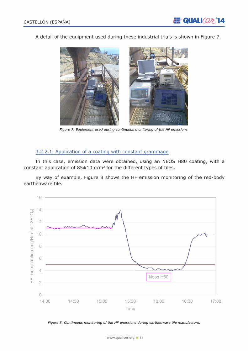
A detail of the equipment used during these industrial trials is shown in Figure 7.
Figure 7. Equipment used during continuous monitoring of the HF emissions.
3.2.2.1. Application of a coating with constant grammage
In this case, emission data were obtained, using an NEOS H80 coating, with a constant application of 85±10 g/m2 for the different types of tiles.
By way of example, Figure 8 shows the HF emission monitoring of the red-body earthenware tile.
Figure 8. Continuous monitoring of the HF emissions during earthenware tile manufacture.

CASTELLÓN (ESPAÑA)
www.qualicer.org 12
Figure 8 clearly shows that the HF emission decreased notably when tiles with an active coating were processed. The emission was constant during the firing of the uncoated tiles. A small gap in the kiln feed produced a slight emission peak at a given moment, owing to the absence of tile bodies in the kiln zone where the HF adsorption took place; the emission then decreased when coated tiles were processed.
The same procedure was followed with different industrial products. The efficiency obtained with the three types of test tiles (keeping grammage constant at 85±10 g/m2) has been plotted in Figure 9. The figure also indicates the specific weight of the processed products, different sizes and thicknesses being involved depending on the type of product.
Figure 9. HF removal efficiency with coating grammage of 85±10 g/m2 as a function of the type of tile.
3.2.2.2. Coating applications with variable grammage
In a second series of 12 industrial trials, coating grammage and composition were modified to adapt the coating to the respective peak firing temperature of the type of tile. The HF emission reduction data have been plotted as a function of the coating/tile mass ratio in Figure 10.

CASTELLÓN (ESPAÑA)
www.qualicer.org 13
Figure 10. HF removal efficiency as a function of the coating/tile mass ratio for different types of tile.
Figure 10 shows that the fluorine retention efficiency increased with the coating/tile mass ratio, displaying a general trend that appeared almost independent of the type of product made. Consequently, it might in principle be inferred that varying the applied coating quantity would enable the efficiency to be modified in order thus to comply with the targeted emission limits. However, the application of very thick coatings on the tile bottom surface is subject to a series of practical constraints (tile weight, soiling of the lines, etc.), which prevent the mass ratio from being raised to very high values, particularly when very thick tiles are processed. No tests were therefore conducted at mass ratios above 8‰, and it was not possible to determine whether this trend was maintained at higher mass ratios.
Although the main advantage of performing industrial trials was carrying out the work in a real scenario (industrial tile sizes and thicknesses, combustion roller kilns, etc.), the principal disadvantage was the concomitant decreased flexibility; nor was the individual effect of the different variables studied. In Figure 10 it may be observed that it was precisely the materials with the lowest mass ratio (greatest thicknesses and sizes) that were processed at the highest temperature (porcelain tile), so that it was difficult to evaluate the individual influence of these two variables on fluorine retention.
The available information enables a general trend to be determined a priori, but a specific study needs to be performed to determine the possibility of using the coating in each particular case.
CASTELLÓN (ESPAÑA)
www.qualicer.org 14
4. CONCLUSIONS
• Coating compositions designed to retain fluorine compounds and avoid fluorine compound emissions into the atmosphere were developed for application on the ceramic tile bottom surface.
• A coating application system was developed that can also be used on an industrial level without changing the usual way of working.
• Coatings with different compositions were tested in industrial conditions. Their abi-lity to reduce HF air emissions and, depending on the type of product made (thic-kness, peak temperature, etc.), to comply with legal requirements on HF air emis-sions was demonstrated.
• The coatings were therefore shown to be effective for reducing fluorine compound emissions and to be an alternative method to the use of conventional treatment systems for such emissions.
5. ACKNOWLEDGEMENTS
This study was funded in the frame of the INNPACTO programme of the Ministry of Science and Innovation (Project IPT-2011-1410-310000).
REFERENCES[1] MONFORT, E.; CELADES, I.; GOMAR, S.; RUEDA, F.; MARTÍNEZ, J. Characterization of acid pollutant emissions
in ceramic tile manufacture. Bol. Soc. Esp. Ceram. Vidr.
[2] MALLOL GASCH, G.; MONFORT GIMENO, E.; BUSANI, G.; LEZAUN NAVARRO, F.J. Depuración de los gases de combustión en la industria cerámica. 2ª. Castellón: Instituto de Tecnología Cerámica, 2001.
[3] E. MONFORT, J. GARCÍA-TEN, I. CELADES, S. GOMAR. Evolution of fluorine emissions during the fast firing of ceramic tile. Appl. clay sci., 38, 250-258, 2008.
[4] Denisen and Vries, 1998. Reduction of fluoride emission from clay materials. ZI Int., 51(1-2), 19-26.
[5] GARCÍA-TEN, J.; MONFORT, E.; GÓMEZ-TENA, M.P.; SANZ, V. Use of coatings to minimise acid emissions during ceramic tile firing. J. Clean Prod., 19 (9-10), 1110-1116, 2011.